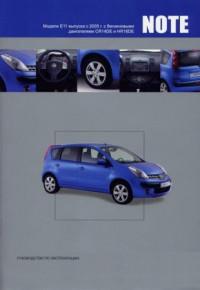
Инструкция по эксплуатации Nissan Note c 2013 г. Техническая информация автомобиля
1. Техническая информация автомобиля
Внешний вид автомобиля
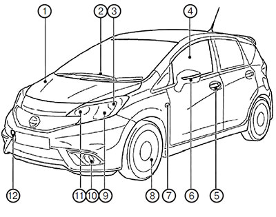
1. Капот. 2. Стеклоочиститель ветрового стекла. 3. Передний габаритный фонарь. 4. Окно. 5. Двери. 6. Наружное зеркало заднего вида. 7. Боковой повторитель указателя поворота. 8. Колесо с шиной в сборе. 9. Передняя блок-фара. 10. Передний противотуманная фара. 11. Передний указатель поворота. 12. Буксировочная проушина.
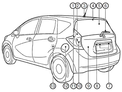
1. Задний габаритный фонарь. 2. Стоп-сигналы. 3. Антенна. 4. Центральный верхний стоп-сигнал. 5. Обогреватель стека двери багажного отделения. 6. Очиститель стекла двери багажного отделения. 7. Фонарь освещения регистрационного знака. 8. Видеокамера заднего вида. 9. Дверь багажного отделения. 10. Фонарь заднего хода. 11. Задний указатель поворота. 12. Лючок заливной горловины топливного бака. 13. Замок задней двери для безопасности детей.
Рекомендуемые эксплуатационные материалы и заправочные емкости агрегатов и систем
В таблице приведены приблизительные значения заправочных емкостей. Реальные значения заправочных емкостей могут несколько отличаться от приведенных в таблице. Во избежание ошибок при заправке агрегатов и систем автомобиля строго следуйте инструкциям.
| Агрегат, система | Заправочная емкость (приблизительный объем) | Рекомендуемые марки топлива и смазки | ||
| Топливный бак | 41 л | См. раздел ниже | ||
| Система смазки двигателя (для замены масла) | При замене масляного фильтра | Двигатели HR12DE | 3,4 л |
Бензиновые двигатели (HR12DE): — Оригинальное моторное масло Nissan с индексом вязкости 0W-20. — Класс качества по API: SN. — Класс качества по ILSAC: GF-5. Бензиновые двигатели (HR12DDR): Дизельные двигатели (K9K): |
| Двигатели HR12DDR | 3,9 л | |||
| Двигатели K9K | 4,8 л | |||
| Без замены масляного фильтра | Двигатели HR12DE | 3,2 л | ||
| Двигатели HR12DDR | 3,7 л | |||
| Двигатели K9K | 4,7 л | |||
| Система охлаждения | Двигатели HR12DE | 5,7 л | Используйте только оригинальную охлаждающую жидкость Nissan. Использование неоригинальной охлаждающей жидкости может привести к коррозии деталей из алюминиевых сплавов системы охлаждения двигателя. Необходимо помнить о том, что гарантийные обязательства завода-изготовителя не распространяются на неисправности системы охлаждения, если применяется неоригинальная охлаждающая жидкость, даже если эти неисправности возникли в течение гарантийного периода. | |
| Двигатели HR12DDR | С механической коробкой передач | 5,8 л | ||
| С бесступенчатой трансмиссией | 6,3 л | |||
| Двигатели K9K | 6,2 л | |||
| Рабочая жидкость для бесступенчатой трансмиссии | 6,9 л | Используйте только оригинальную рабочую жидкость Nissan CVT Fluid NS-3. Использование рабочей жидкости, отличной от Nissan CVT Fluid NS-3, приведет к повреждениям бесступенчатого вариатора CVT, устранение которых не покрывается гарантийными обязательствами компании Nissan. | ||
| Масло для механических коробок передач | Двигатели HR12DE и HR12DDR | 2,7 л | Используйте оригинальное трансмиссионное масло Nissan MT-XZ с индексом вязкости SAE 75-W80 или аналогичное. Если оригинальное трансмиссионное масло Nissan MT-XZ недоступно, в качестве временной замены может быть использовано масло API GL-4 с индексом вязкости SAE 75W-80. Однако используйте оригинальное трансмиссионное масло Nissan MT-XZ, как только оно будет доступно. | |
| Двигатели K9K | 2,3 л | |||
| Тормозная жидкость и рабочая жидкость гидропривода сцепления | Долейте до необходимого уровня | Оригинальная тормозная жидкость Nissan DOT 3 или DOT 4 | ||
| Универсальная консистентная смазка | – | Смазка NLGI № 2 (с литиевым загустителем) | ||
| Хладагент для системы кондиционирования воздуха | – | HFO-1234yf (R1234yf) | ||
| Масло для системы кондиционирования воздуха | – | Масло Nissan для систем кондиционирования YR20 (POE) или аналогичное |
Рекомендуемое топливо
Автомобили с бензиновыми двигателями
Внимание:
Запрещается использовать этилированный бензин. Использование этилированного бензина приводит к выходу из строя трехкомпонентного нейтрализатора отработанных газов.
Используйте неэтилированный бензин с октановым числом не менее 95 (по исследовательскому методу).
Автомобили с бензиновыми дизельными двигателями
Используйте дизельное топливо ЕМ590 с цетановым числом не менее 50.
Примечание:
Допускается использование только дизельного топлива с низким содержанием серы.
Если имеется два типа дизельного топлива, то применяйте зимнее или летнее топливо в зависимости от температурных условий:
— При температуре выше -7 ⁰С — летний сорт дизельного топлива;
— При температуре ниже -7 ⁰С — зимний сорт дизельного топлива.
При возникновении любых сомнений обратитесь к официальному дилеру компании Nissan.
Внимание:
— Не используйте в дизельном двигателе нефтепродукты, предназначенные для тепловых установок, бензин или иные виды горючего, поскольку это приведет к неисправности двигателя.
— Не добавляйте в дизельное топливо бензин или иные виды топлива.
— Запрещается заправлять автомобиль дизельным топливом летнего сорта, если температура окружающего воздуха ниже -7 ⁰С. При охлаждении в летнем топливе интенсивно выпадают кристаллы парафина. В результате двигатель начинает работать с перебоями или глохнет.
Рекомендации по выбору вязкости моторного масла
Моторное масло для бензиновых двигателей
Предпочтительно использовать моторное масло вязкостью 0W-20. При отсутствии масла 0W-20, пользуясь диаграммой, выберите масло с наиболее подходящей вязкостью для данного температурного диапазона.
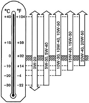
Моторное масло для дизельных двигателей
Используйте ТОЛЬКО масло 5W-30 (для сажевого фильтра DPF).
Хладагент и смазочные материалы для системы кондиционирования воздуха
Система кондиционирования воздуха на вашем автомобиле должна заправляться хладагентом R1234yf. Для смазки системы необходимо применять масло Nissan для систем кондиционирования воздуха, тип YR20, или его полный аналог. Применение любого другого хладагента или масла приведет к серьезным повреждениям системы кондиционирования воздуха, из-за чего может потребоваться полная замена системы.
Экологическая программа компании Nissan
Выброс хладагентов в атмосферу запрещен во многих странах и регионах. Хладагент R1234yf, применяемый на вашем автомобиле, не разрушает озоновый слой атмосферы Земли, но его выход в атмосферу может влиять на глобальные процессы потепления климата на Земле. Компания Nissan рекомендует выполнять дозаправку и утилизацию хладагента надлежащим образом. Для технического обслуживания кондиционера обратитесь на сервисную станцию официального дилера Nissan.
Технические характеристики двигателей
| Модель двигателя | HR12DE | HR12DDR | K9K | |
| Тип | Бензиновый, 4-тактный, два верхних распределительных вала | Бензиновый, 4-тактный, два верхних распределительных вала | Дизельный, 4-тактный | |
| Количество и расположение цилиндров | 3, рядное | 3, рядное | 4, рядное | |
| Диаметр цилиндра х ход поршня, | 78,0 х 83,6 мм | 78,0 х 83,6 мм | 76,0 х 80,5 мм | |
| Рабочий объем | 1198 см³ | 1198 см³ | 1461 см³ | |
| Частота холостого хода, об/мин | 750 ± 50 об/мин | 780 ± 50 об/мин | 7850 ± 50 об/мин | |
| Угол опережения зажигания (по углу поворота коленчатого вала, град, до ВМТ) | 9°±2 | 11°±2 | – | |
| Свечи зажигания | Тип | DILKAR6A11 | DILKAR7E11HS | – |
| Зазор | 1,1 мм | 1,1 мм | – | |
| Тип привода распределительного вала | Цепной | Цепной | Ременной |
Колеса и шины
| Стандартное колесо | Запасное колесо | |
| Размер шин | 185/65R15 88H | T125/70D15* |
| 195/55R16 87V |
Примечание:
*: Только для временного использования — для некоторых вариантов исполнения автомобиля.
Колесные диски
| Колесо | Диск | Размер | Вылет |
| Стандартное колесо | Стальной | 15×5-1/2J | 40 мм |
| Алюминиевый | 15×5-1/2J | ||
| 16×6J | |||
| Запасное колесо | Стальной | 15×4T* |
Размеры автомобиля
| Габаритная длина | 4100 мм |
| Габаритная ширина | 1695 мм |
| Габаритная высота | 1535 мм |
| Колея передних колес | 1480 мм* |
| 1470 мм** | |
| Колея задних колес | 1485 мм* |
| 1475 мм** | |
| Колесная база | 2600 мм |
Примечание:
*: С размером шин 185/65R15.
**: С размером шин 195/55R16.
Рекомендации владельцу при поездке за границу и идентификационная перерегистрация автомобиля
Если вы планируете совершить поездку в другую страну, прежде всего вам необходимо выяснить, имеется ли в ней топливо, подходящее для двигателя вашего автомобиля. Помните, что эксплуатация автомобиля на топливе с низким октановым (бензиновые двигатели) или цетановым (дизели) числом приведет к выходу двигателя из строя. Поэтому не следует планировать поездки на автомобиле в те страны, где отсутствует топливо требуемого качества.
Перед перерегистрацией вашего автомобиля в другой стране, обратитесь в соответствующие уполномоченные органы, чтобы убедиться в том, что ваш автомобиль соответствует всем требованиям, действующим в этой стране, так как может оказаться, что ваш автомобиль невозможно адаптировать к этим требованиям. В отдельных случаях автомобиль невозможно модернизировать под требования местных стандартов. В других случаях автомобиль должен подвергнуться определенным модификациям, чтобы он соответствовал местному законодательству. Из-за отличий в местных требованиях по безопасности и токсичности выбросов в атмосферу автомобили, поставляемые на различные рынки, могут отличаться по комплектации.
Примечание:
Ответственность за вывоз, перерегистрацию автомобиля в другой стране и связанную с ней модернизацию автомобиля лежит на владельце. Компания Nissan не несет никакой ответственности за возникшие в связи с этим неудобства. Ответственность за транспортировку автомобиля, выполнение необходимых изменений в конструкции и повторную регистрацию автомобиля несет исключительно владелец автомобиля.
Идентификационные данные автомобиля
Идентификационная табличка автомобиля
Табличка находится в указанном на рисунке месте.
Идентификационный номер автомобиля (VIN)
Номер выбит в месте, указанном на рисунке.
Примечание:
Запрещается закрывать, красить, сваривать, резать, сверлить, изменять или удалять идентификационный номер автомобиля (VIN).
Номер двигателя
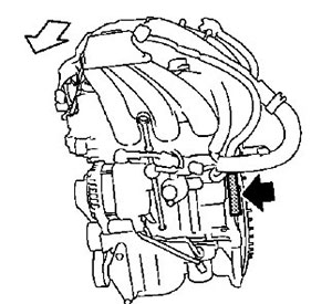
Двигатели HR12DE
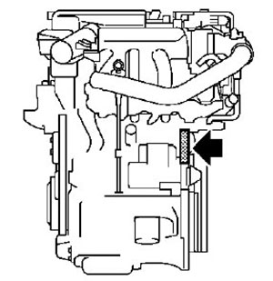
Двигатели HR12DDR
Двигатели K9K
Номер двигателя выбит на блоке цилиндров, в месте, указанном на рисунке.
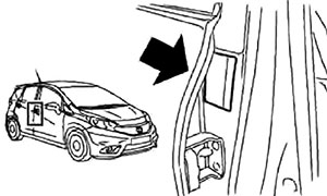
Табличка с информацией о шинах

На табличке, наклеенной на средней стойке кузова в проеме водительской двери, приведено рекомендуемое давление воздуха для холодных шин.
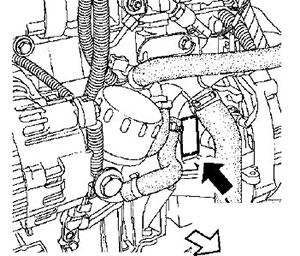
Табличка с техническими данными кондиционера
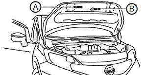
А — Табличка с техническими данными кондиционера. В — Табличка тормозной жидкости.
Таблички находятся в местах, указанных на рисунке.
Приборы управления
Приборная панель и органы управления
Измерительные приборы и указатели
Контрольные лампы, индикаторы, звуковые предупреждающие сигналы
Охранная система
Выключатель стеклоочистителя и омывателя
Обогреватели заднего стекла и наружных зеркал заднего вида
Весь список статей этого раздела »
Подготовка к движению
Ключи от автомобиля
Встроенный в ключ пульт дистанционного управления центральным замком
Система «Intelligent key»
Замки дверей
Открывание крышки капота
Дверка заливной горловины топливного бака
Весь список статей этого раздела »
Запуск двигателя и вождение
Обкатка автомобиля
Турбокомпрессор (модели с дизельным двигателем)
Замок зажигания
Ручка выключателя зажигания
Запуск двигателя
Вождение автомобиля
Весь список статей этого раздела »
Техническое обслуживание
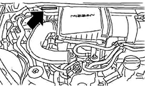
Моторный отсек автомобиля с двигателем 1,4 л
Моторный отсек автомобиля с двигателем 1,6 л
Система охлаждения двигателя
Замена охлаждающей жидкости
Моторное масло
Замена моторного масла
Весь список статей этого раздела »
Техническая информация
Заправочные емкости и рабочие жидкости
Технические характеристики двигателей
Колеса и шины
Размеры автомобиля
Идентификационные данные автомобиля
Точки упора для подъёма автомобиля
Весь список статей этого раздела »
Этот раздел доступен на: английском, болгарском, белорусском, украинском, сербском, хорватском, румынском, польском, словацком, венгерском
Отправить эту информацию вашим друзьям:
Ссылка в разных форматах на этот раздел
TEXTHTMLBB Code
Мультимедийное руководство на английском языке по техническому обслуживанию и ремонту автомобиля Nissan Note серии E11.
- Автор: —
- Издательство: Nissan
- Год издания: 2006
- Страниц: —
- Формат: —
- Размер: 60,5 Mb
Руководство на английском языке по техническому обслуживанию и ремонту автомобиля Nissan Note серии E12.
- Автор: —
- Издательство: Nissan
- Год издания: 2013
- Страниц: —
- Формат: PDF
- Размер: 60,0 Mb
Сборник руководств по эксплуатации и техническому обслуживанию автомобиля Nissan Note с 2005 года выпуска.
- Автор: —
- Издательство: Nissan Europe
- Год издания: 2006/2010
- Страниц: 264/229
- Формат: PDF
- Размер: 12,9 Mb

Руководство по эксплуатации, техническому обслуживанию и ремонту автомобиля Nissan Note с 2005 года выпуска с бензиновыми двигателями объемом 1,4/1,6 л.
- Автор: —
- Издательство: Третий Рим
- Год издания: 2011
- Страниц: 651
- Формат: PDF
- Размер: 77,8 Mb

Руководство по эксплуатации и техническому обслуживанию автомобиля Nissan Note с 2005 года выпуска.
- Автор: —
- Издательство: MoToR
- Год издания: —
- Страниц: 274
- Формат: —
- Размер: —
Руководство по эксплуатации, техническому обслуживанию и ремонту автомобиля Nissan Note серии E11 с 2005 года выпуска с бензиновыми двигателями объемом 1,4/1,6 л.
- Автор: —
- Издательство: Автонавигатор
- Год издания: —
- Страниц: 447
- Формат: PDF
- Размер: 26,7 Mb

Руководство по техническому обслуживанию и ремонту автомобиля Nissan Note серии E11 2005-2009 годов выпуска.
- Автор: —
- Издательство: Автонавигатор
- Год издания: —
- Страниц: 448
- Формат: —
- Размер: —

Руководство по эксплуатации и ремонту автомобиля Nissan Note с 2013 года выпуска с бензиновыми и дизельными двигателями.
- Автор: —
- Издательство: Монолит
- Год издания: —
- Страниц: 468
- Формат: PDF
- Размер: —

ENGINE
SECTION
ACC
ACCELERATOR CONTROL SYSTEM
A
ACC
C
D
E
CONTENTS
PRECAUTION ……………………………………….. 2
PRECAUTIONS …………………………………………… 2
Precaution for Supplemental Restraint System
(SRS) «AIR BAG» and «SEAT BELT PRE-TENSIONER» …………………………………………………………. 2
REMOVAL AND INSTALLATION ……………. 3
ACCELERATOR CONTROL SYSTEM …………… 3
Removal and Installation …………………………………… 3
Inspection ……………………………………………………….. 3
F
SERVICE DATA AND SPECIFICATIONS
(SDS) ……………………………………………………. 5
G
SERVICE DATA AND SPECIFICATIONS
(SDS) ………………………………………………………… 5
H
Accelerator Control …………………………………………… 5
Exploded View …………………………………………………. 3
I
J
K
L
M
N
O
P
Revision: April 2013
ACC-1
2014 Note
PRECAUTIONS
< PRECAUTION >
PRECAUTION
PRECAUTIONS
Precaution for Supplemental Restraint System (SRS) «AIR BAG» and «SEAT BELT
PRE-TENSIONER»
INFOID:0000000009452281
The Supplemental Restraint System such as “AIR BAG” and “SEAT BELT PRE-TENSIONER”, used along
with a front seat belt, helps to reduce the risk or severity of injury to the driver and front passenger for certain
types of collision. Information necessary to service the system safely is included in the SR and SB section of
this Service Manual.
WARNING:
• To avoid rendering the SRS inoperative, which could increase the risk of personal injury or death in
the event of a collision which would result in air bag inflation, all maintenance must be performed by
an authorized NISSAN/INFINITI dealer.
• Improper maintenance, including incorrect removal and installation of the SRS, can lead to personal
injury caused by unintentional activation of the system. For removal of Spiral Cable and Air Bag
Module, see the SR section.
• Do not use electrical test equipment on any circuit related to the SRS unless instructed to in this
Service Manual. SRS wiring harnesses can be identified by yellow and/or orange harnesses or harness connectors.
PRECAUTIONS WHEN USING POWER TOOLS (AIR OR ELECTRIC) AND HAMMERS
WARNING:
• When working near the Airbag Diagnosis Sensor Unit or other Airbag System sensors with the Ignition ON or engine running, DO NOT use air or electric power tools or strike near the sensor(s) with a
hammer. Heavy vibration could activate the sensor(s) and deploy the air bag(s), possibly causing
serious injury.
• When using air or electric power tools or hammers, always switch the Ignition OFF, disconnect the
battery and wait at least three minutes before performing any service.
Revision: April 2013
ACC-2
2014 Note
ACCELERATOR CONTROL SYSTEM
< REMOVAL AND INSTALLATION >
REMOVAL AND INSTALLATION
A
ACCELERATOR CONTROL SYSTEM
Exploded View
INFOID:0000000009015312
ACC
C
D
E
F
G
JSBIA1087GB
1.
Accelerator pedal
2. Brake pedal bracket
A.
H
Locating hook
B. Locating pin
I
Removal and Installation
INFOID:0000000009443948
REMOVAL
1.
2.
J
Disconnect harness connector (A) from the accelerator pedal.
Remove bolts (B) and accelerator pedal (1).
CAUTION:
• Do not disassemble accelerator pedal.
• Do not drop or impact accelerator pedal.
• Do not expose accelerator pedal to water.
K
L
M
ALBIA1149ZZ
INSTALLATION
N
Installation is in the reverse order of removal.
NOTE:
• Insert locating pin into brake pedal bracket to position accelerator pedal.
• Perform accelerator pedal inspection. Refer to ACC-3, «Inspection».
Inspection
O
INFOID:0000000009443949
P
INSPECTION AFTER INSTALLATION
Revision: April 2013
ACC-3
2014 Note
ACCELERATOR CONTROL SYSTEM
< REMOVAL AND INSTALLATION >
• Check that the accelerator pedal moves smoothly within the specified range.
Accelerator pedal stroke (A) : Refer to ACC-5, «Accelerator Control».
ALBIA1151ZZ
• Check the accelerator pedal height.
Accelerator pedal height
: Refer to ACC-5, «Accelerator Control».
CAUTION:
• Whenever the harness connector of the accelerator pedal position sensor has been disconnected,
perform “ACCELERATOR PEDAL RELEASED POSITION LEARNING”. Refer to EC-113, «Work Procedure».
• The accelerator pedal should return smoothly to the fully released position.
Revision: April 2013
ACC-4
2014 Note
SERVICE DATA AND SPECIFICATIONS (SDS)
< SERVICE DATA AND SPECIFICATIONS (SDS)
SERVICE DATA AND SPECIFICATIONS (SDS)
A
SERVICE DATA AND SPECIFICATIONS (SDS)
Accelerator Control
INFOID:0000000009443950
ACC
Unit: mm (in)
C
D
E
ALBIA1151ZZ
Accelerator pedal stroke (A)
49.8 — 52.6 (1.96 — 2.07)
Accelerator pedal height
113.0 — 123.0 (4.45 — 4.84)
F
G
H
I
J
K
L
M
N
O
P
Revision: April 2013
ACC-5
2014 Note
DRIVER INFORMATION & MULTIMEDIA
SECTION
AV
AUDIO, VISUAL & NAVIGATION SYSTEM
A
B
C
D
E
CONTENTS
BASE AUDIO
DIAGNOSIS AND REPAIR WORKFLOW …….. 23
PRECAUTION ……………………………………….. 5
PRECAUTIONS …………………………………………… 5
Work Flow ……………………………………………………….23
DTC/CIRCUIT DIAGNOSIS ……………………. 25
Precaution for Supplemental Restraint System
(SRS) «AIR BAG» and «SEAT BELT PRE-TENSIONER» …………………………………………………………. 5
Precaution for Work ………………………………………….. 5
POWER SUPPLY AND GROUND CIRCUIT …. 25
PREPARATION …………………………………….. 6
FRONT DOOR SPEAKER ………………………….. 26
PREPARATION …………………………………………… 6
Special Service Tools ………………………………………… 6
Commercial Service Tools …………………………………. 6
SYSTEM DESCRIPTION ………………………… 7
COMPONENT PARTS …………………………………. 7
Component Parts Location …………………………………. 7
Audio unit ………………………………………………………… 7
Speaker …………………………………………………………… 7
Rod Antenna, Antenna Amp. and Antenna Feeder
…… 8
AUDIO UNIT ………………………………………………………25
AUDIO UNIT : Diagnosis Procedure …………………..25
Diagnosis Procedure ………………………………………..26
Diagnosis Procedure ………………………………………..28
AUDIO SYSTEM ……………………………………….. 30
I
J
K
Symptom Table ……………………………………………….30
NORMAL OPERATING CONDITION …………… 32
Description ………………………………………………………32
L
REMOVAL AND INSTALLATION …………… 33
System Description …………………………………………. 10
Exploded View …………………………………………………33
Removal and Installation …………………………………..33
DIAGNOSIS SYSTEM (AUDIO UNIT) …………….11
Diagnosis Description ……………………………………… 11
On Board Diagnosis Function …………………………… 11
FRONT DOOR SPEAKER ………………………….. 34
ECU DIAGNOSIS INFORMATION ………….. 14
REAR DOOR SPEAKER ……………………………. 35
M
AV
Removal and Installation …………………………………..34
O
Removal and Installation …………………………………..35
Reference Value …………………………………………….. 14
ROD ANTENNA ………………………………………… 36
WIRING DIAGRAM ……………………………….. 16
Exploded View …………………………………………………36
Removal and Installation …………………………………..36
BASE AUDIO ……………………………………………..16
ANTENNA FEEDER …………………………………… 37
BASIC INSPECTION …………………………….. 23
Revision: April 2013
H
SYMPTOM DIAGNOSIS ………………………… 30
AUDIO UNIT ……………………………………………… 33
Wiring Diagram ………………………………………………. 16
G
REAR DOOR SPEAKER ……………………………. 28
SYSTEM …………………………………………………….10
AUDIO UNIT ……………………………………………….14
F
AV-1
Feeder Layout …………………………………………………37
DISPLAY AUDIO
2014 Note
P
PRECAUTION ……………………………………… 38
POWER SUPPLY AND GROUND CIRCUIT ….. 72
PRECAUTIONS …………………………………………. 38
AUDIO UNIT …………………………………………………….. 72
AUDIO UNIT : Diagnosis Procedure ………………….. 72
Precaution for Supplemental Restraint System
(SRS) «AIR BAG» and «SEAT BELT PRE-TENSIONER» ……………………………………………………….. 38
Precaution for Trouble Diagnosis ……………………… 38
Precaution for Harness Repair …………………………. 38
Precaution for Work ………………………………………… 39
PREPARATION ……………………………………. 40
PREPARATION …………………………………………. 40
Special Service Tools ……………………………………… 40
Commercial Service Tools ……………………………….. 40
SYSTEM DESCRIPTION ………………………. 41
COMPONENT PARTS ………………………………… 41
Component Parts Location ………………………………. 41
Audio Unit ……………………………………………………… 42
Speaker ………………………………………………………… 42
USB Interface ………………………………………………… 42
Bluetooth Control Unit …………………………………….. 43
Bluetooth Antenna ………………………………………….. 43
Steering Switch ………………………………………………. 43
Microphone ……………………………………………………. 43
Rear View Camera …………………………………………. 44
Rod Antenna, Antenna Amp. and Antenna Feeder
… 44
BLUETOOTH® CONTROL UNIT ………………………… 72
BLUETOOTH® CONTROL UNIT : Diagnosis Procedure …………………………………………………………… 72
FRONT DOOR SPEAKER …………………………… 74
Diagnosis Procedure ……………………………………….. 74
REAR DOOR SPEAKER …………………………….. 76
Diagnosis Procedure ……………………………………….. 76
BLUETOOTH® VOICE SIGNAL CIRCUIT …….. 78
Diagnosis Procedure ……………………………………….. 78
BLUETOOTH® CONTROL SIGNAL CIRCUIT… 80
Diagnosis Procedure ……………………………………….. 80
REAR VIEW CAMERA IMAGE SIGNAL CIRCUIT …………………………………………………………. 81
Diagnosis Procedure ……………………………………….. 81
MICROPHONE SIGNAL CIRCUIT ……………….. 83
Diagnosis Procedure ……………………………………….. 83
STEERING SWITCH …………………………………… 85
Diagnosis Procedure ……………………………………….. 85
USB CONNECTOR ……………………………………. 87
SYSTEM ……………………………………………………. 46
Diagnosis Procedure ……………………………………….. 87
System Description …………………………………………. 46
SYMPTOM DIAGNOSIS ………………………. 88
DIAGNOSIS SYSTEM (AUDIO UNIT) …………… 48
Description …………………………………………………….. 48
On Board Diagnosis Function …………………………… 48
DIAGNOSIS SYSTEM (BLUETOOTH® CONTROL UNIT) ………………………………………………. 53
AUDIO SYSTEM ………………………………………… 88
Symptom Table ………………………………………………. 88
NORMAL OPERATING CONDITION ……………. 91
Description …………………………………………………….. 91
Diagnosis Description ……………………………………… 53
Work Flow ……………………………………………………… 53
REMOVAL AND INSTALLATION ………….. 93
ECU DIAGNOSIS INFORMATION ………….. 54
Exploded View ……………………………………………….. 93
Removal and Installation ………………………………….. 93
AUDIO UNIT ……………………………………………… 54
Reference Value …………………………………………….. 54
BLUETOOTH® CONTROL UNIT …………………. 57
Reference Value …………………………………………….. 57
WIRING DIAGRAM ………………………………. 59
DISPLAY AUDIO ……………………………………….. 59
Wiring Diagram ………………………………………………. 59
BASIC INSPECTION …………………………….. 70
DIAGNOSIS AND REPAIR WORKFLOW ……… 70
Work Flow ……………………………………………………… 70
DTC/CIRCUIT DIAGNOSIS ……………………. 72
Revision: April 2013
AUDIO UNIT ……………………………………………… 93
FRONT DOOR SPEAKER …………………………… 94
Removal and Installation ………………………………….. 94
REAR DOOR SPEAKER …………………………….. 95
Removal and Installation ………………………………….. 95
USB INTERFACE ………………………………………. 96
Removal and Installation ………………………………….. 96
REAR VIEW CAMERA ……………………………….. 97
Removal and Installation ………………………………….. 97
BLUETOOTH® CONTROL UNIT …………………. 98
Removal and Installation ………………………………….. 98
BLUETOOTH® ANTENNA ………………………….. 99
AV-2
2014 Note
Removal and Installation ………………………………….. 99
NAVIGATION SYSTEM ……………………………. 121
Wiring Diagram ……………………………………………… 121
STEERING SWITCH …………………………………. 100
Removal and Installation ………………………………… 100
BASIC INSPECTION …………………………… 132
MICROPHONE …………………………………………. 101
DIAGNOSIS AND REPAIR WORKFLOW …… 132
Removal and Installation ………………………………… 101
ROD ANTENNA ……………………………………….. 102
Exploded View ……………………………………………… 102
Removal and Installation ………………………………… 102
ANTENNA FEEDER ………………………………….. 103
Feeder Layout ………………………………………………. 103
NAVIGATION
PRECAUTION …………………………………….. 104
PRECAUTIONS ………………………………………… 104
Precaution for Supplemental Restraint System
(SRS) «AIR BAG» and «SEAT BELT PRE-TENSIONER» ……………………………………………………… 104
Precaution for Trouble Diagnosis …………………….. 104
Precaution for Harness Repair ………………………… 104
Precaution for Work ………………………………………. 105
PREPARATION ………………………………….. 106
PREPARATION ………………………………………… 106
Special Service Tools …………………………………….. 106
Commercial Service Tools ……………………………… 106
SYSTEM DESCRIPTION ……………………… 107
INSPECTION AND ADJUSTMENT ……………. 134
ADDITIONAL SERVICE WHEN REPLACING AV
CONTROL UNIT ……………………………………………… 134
ADDITIONAL SERVICE WHEN REPLACING AV
CONTROL UNIT : Description …………………………. 134
ADDITIONAL SERVICE WHEN REPLACING AV
CONTROL UNIT : Work Procedure ………………….. 134
CONFIGURATION (AV CONTROL UNIT) …………… 134
CONFIGURATION (AV CONTROL UNIT) : Description ……………………………………………………….. 135
CONFIGURATION (AV CONTROL UNIT) : Work
Procedure …………………………………………………….. 135
CONFIGURATION (AV CONTROL UNIT) : Configuration List ………………………………………………… 136
DTC/CIRCUIT DIAGNOSIS ………………….. 137
DTC Logic …………………………………………………….. 137
Diagnosis Procedure …………………………………….. 137
DTC Logic …………………………………………………….. 138
DTC Logic …………………………………………………….. 139
U1229 AV CONTROL UNIT ………………………. 140
E
F
G
H
I
J
K
DTC Logic …………………………………………………….. 140
U122F AV CONTROL UNIT ………………………. 141
DTC Logic …………………………………………………….. 141
U1244 GPS ANTENNA …………………………….. 142
DTC Logic …………………………………………………….. 142
Diagnosis Procedure ……………………………………… 142
L
M
U1263 USB ……………………………………………… 143 AV
System Description ……………………………………….. 111
DTC Logic …………………………………………………….. 143
Diagnosis Procedure ……………………………………… 143
DIAGNOSIS SYSTEM (AV CONTROL UNIT).. 115
U1264 ANTENNA AMP. ……………………………. 144
O
DTC Logic …………………………………………………….. 144
Diagnosis Procedure ……………………………………… 144
U12AA CONFIGURATION ERROR ……………. 145
DTC Logic …………………………………………………….. 145
Diagnosis Procedure ……………………………………… 145
AV CONTROL UNIT ………………………………….. 117
Reference Value …………………………………………… 117
DTC Index ……………………………………………………. 120
U12AC AV CONTROL UNIT ……………………… 146
WIRING DIAGRAM ……………………………… 121
U12AD AV CONTROL UNIT ……………………… 147
Revision: April 2013
D
U1010 CONTROL UNIT (CAN) ………………….. 138
Component Parts Location ……………………………… 107
AV Control Unit …………………………………………….. 107
Speaker ……………………………………………………….. 108
USB Interface and AUX In Jack ………………………. 108
Steering Switch …………………………………………….. 109
Microphone ………………………………………………….. 109
Rear View Camera ………………………………………… 109
Rod Antenna, Antenna Amp. and Antenna Feeder
.. 109
GPS Antenna ……………………………………………….. 110
SD Card ………………………………………………………. 110
ECU DIAGNOSIS INFORMATION ………… 117
C
U1000 CAN COMM CIRCUIT ……………………. 137
U1217 AV CONTROL UNIT ………………………. 139
Description …………………………………………………… 115
On Board Diagnosis Function …………………………. 115
CONSULT Function ………………………………………. 116
B
Work Flow …………………………………………………….. 132
COMPONENT PARTS ………………………………. 107
SYSTEM ………………………………………………….. 111
A
DTC Logic …………………………………………………….. 146
AV-3
2014 Note
P
DTC Logic ……………………………………………………..147
SYMPTOM DIAGNOSIS ……………………… 166
U12AE AV CONTROL UNIT ………………………. 148
MULTI AV SYSTEM ………………………………….. 166
DTC Logic ……………………………………………………..148
U12AF AV CONTROL UNIT ………………………. 149
DTC Logic ……………………………………………………..149
U12B0 POWER SUPPLY VOLTAGE ………….. 150
DTC Logic ……………………………………………………..150
Diagnosis Procedure ………………………………………150
U12B1 POWER SUPPLY VOLTAGE ………….. 151
Symptom Table …………………………………………….. 166
NORMAL OPERATING CONDITION …………… 169
Description …………………………………………………… 169
REMOVAL AND INSTALLATION …………. 178
AV CONTROL UNIT ………………………………….. 178
Removal and Installation ………………………………… 178
DTC Logic ……………………………………………………..151
Diagnosis Procedure ………………………………………151
FRONT DOOR SPEAKER ………………………….. 179
U1310 AV CONTROL UNIT ……………………….. 152
REAR DOOR SPEAKER ……………………………. 180
DTC Logic ……………………………………………………..152
Removal and Installation ………………………………… 180
POWER SUPPLY AND GROUND CIRCUIT … 153
USB INTERFACE ……………………………………… 181
AV CONTROL UNIT ………………………………………….153
AV CONTROL UNIT : Diagnosis Procedure ……….153
FRONT DOOR SPEAKER …………………………. 154
Diagnosis Procedure ………………………………………154
REAR DOOR SPEAKER …………………………… 156
Diagnosis Procedure ………………………………………156
Removal and Installation ………………………………… 179
Removal and Installation ………………………………… 181
AUXILIARY INPUT JACK ………………………….. 182
Removal and Installation ………………………………… 182
STEERING SWITCH ………………………………….. 183
Removal and Installation ………………………………… 183
MICROPHONE …………………………………………. 184
Removal and Installation ………………………………… 184
REAR VIEW CAMERA IMAGE SIGNAL CIRCUIT ……………………………………………………….. 158
REAR VIEW CAMERA ………………………………. 185
Diagnosis Procedure ………………………………………158
Removal and Installation ………………………………… 185
MICROPHONE SIGNAL CIRCUIT ……………… 160
GPS ANTENNA ………………………………………… 186
Diagnosis Procedure ………………………………………160
Removal and Installation ………………………………… 186
STEERING SWITCH …………………………………. 162
ROD ANTENNA ………………………………………… 187
Diagnosis Procedure ………………………………………162
Exploded View ……………………………………………… 187
Removal and Installation ………………………………… 187
USB CONNECTOR …………………………………… 164
Diagnosis Procedure ………………………………………164
AUXILIARY INPUT JACK …………………………. 165
ANTENNA FEEDER ………………………………….. 188
Feeder Layout ………………………………………………. 188
Diagnosis Procedure ………………………………………165
Revision: April 2013
AV-4
2014 Note
PRECAUTIONS
[BASE AUDIO]
< PRECAUTION >
PRECAUTION
A
PRECAUTIONS
Precaution for Supplemental Restraint System (SRS) «AIR BAG» and «SEAT BELT
PRE-TENSIONER»
B
INFOID:0000000009640319
The Supplemental Restraint System such as “AIR BAG” and “SEAT BELT PRE-TENSIONER”, used along
with a front seat belt, helps to reduce the risk or severity of injury to the driver and front passenger for certain
types of collision. Information necessary to service the system safely is included in the SR and SB section of
this Service Manual.
WARNING:
• To avoid rendering the SRS inoperative, which could increase the risk of personal injury or death in
the event of a collision which would result in air bag inflation, all maintenance must be performed by
an authorized NISSAN/INFINITI dealer.
• Improper maintenance, including incorrect removal and installation of the SRS, can lead to personal
injury caused by unintentional activation of the system. For removal of Spiral Cable and Air Bag
Module, see the SR section.
• Do not use electrical test equipment on any circuit related to the SRS unless instructed to in this
Service Manual. SRS wiring harnesses can be identified by yellow and/or orange harnesses or harness connectors.
PRECAUTIONS WHEN USING POWER TOOLS (AIR OR ELECTRIC) AND HAMMERS
WARNING:
• When working near the Airbag Diagnosis Sensor Unit or other Airbag System sensors with the Ignition ON or engine running, DO NOT use air or electric power tools or strike near the sensor(s) with a
hammer. Heavy vibration could activate the sensor(s) and deploy the air bag(s), possibly causing
serious injury.
• When using air or electric power tools or hammers, always switch the Ignition OFF, disconnect the
battery and wait at least three minutes before performing any service.
Precaution for Work
INFOID:0000000009640320
C
D
E
F
G
H
I
J
• When removing or disassembling each component, be careful not to damage or deform it. If a component
may be subject to interference, be sure to protect it with a shop cloth.
• When removing (disengaging) components with a screwdriver or similar tool, be sure to wrap the component K
with a shop cloth or vinyl tape to protect it.
• Protect the removed parts with a shop cloth and prevent them from being dropped.
• Replace a deformed or damaged clip.
L
• If a part is specified as a non-reusable part, always replace it with a new one.
• Be sure to tighten bolts and nuts securely to the specified torque.
• After installation is complete, be sure to check that each part works properly.
• Follow the steps below to clean components:
M
— Water soluble dirt:
• Dip a soft cloth into lukewarm water, wring the water out of the cloth and wipe the dirty area.
• Then rub with a soft, dry cloth.
AV
— Oily dirt:
• Dip a soft cloth into lukewarm water with mild detergent (concentration: within 2 to 3%) and wipe the dirty
area.
O
• Then dip a cloth into fresh water, wring the water out of the cloth and wipe the detergent off.
• Then rub with a soft, dry cloth.
— Do not use organic solvent such as thinner, benzene, alcohol or gasoline.
— For genuine leather seats, use a genuine leather seat cleaner.
P
Revision: April 2013
AV-5
2014 Note
PREPARATION
[BASE AUDIO]
< PREPARATION >
PREPARATION
PREPARATION
Special Service Tools
INFOID:0000000009640321
The actual shapes of Kent-Moore tools may differ from those of special service tools illustrated here.
Tool number
(Kent-Moore No.)
Tool name
Description
—
(J-46534)
Trim Tool Set
Removing trim components
AWJIA0483ZZ
Commercial Service Tools
INFOID:0000000009640322
Tool name
Description
Power tool
Loosening nuts, screws and bolts
PIIB1407E
Revision: April 2013
AV-6
2014 Note
COMPONENT PARTS
[BASE AUDIO]
< SYSTEM DESCRIPTION >
SYSTEM DESCRIPTION
A
COMPONENT PARTS
Component Parts Location
INFOID:0000000009509282
B
C
D
E
F
AWNIA3058ZZ
No.
Component
1.
Rod antenna
2.
Antenna base (antenna amp.)
3.
Rear door speaker RH
4.
Front door speaker RH
5.
Front door speaker LH
6.
Rear door speaker LH
7.
Audio unit
G
Function
Refer to AV-8, «Rod Antenna, Antenna Amp. and Antenna Feeder».
H
Refer to AV-7, «Speaker».
I
Refer to AV-7, «Audio unit».
J
Audio unit
INFOID:0000000009509278
K
DESCRIPTION
• AM/FM electronic tuner radio, CD player, and auxiliary input jack
are integrated into the audio unit.
• The audio unit supports CD-R/CD-RW and provides the playback
of MP3/WMA music files.
L
M
AV
JSNIA5416ZZ
Speaker
INFOID:0000000009509279
O
FRONT DOOR SPEAKER
• 16.5 cm (6.5 in) speakers are installed in the bottom of the front doors.
Revision: April 2013
AV-7
P
2014 Note
COMPONENT PARTS
< SYSTEM DESCRIPTION >
• Sound signals are input from the audio unit to output high, mid and
low range sounds.
[BASE AUDIO]
JPNIA1454ZZ
REAR DOOR SPEAKER
• 16.5 cm (6.5 in) speakers are installed in the bottom of the rear doors.
• Sound signals are input from the audio unit to output high, mid and
low range sounds.
JPNIA1454ZZ
Rod Antenna, Antenna Amp. and Antenna Feeder
INFOID:0000000009509280
RADIO ANTENNA
AM/FM radio rod antenna and antenna base is located on the rear of the roof. The antenna amp. is built into
the antenna base.
AWNIA3059GB
ANTENNA FEEDER LAYOUT
Revision: April 2013
AV-8
2014 Note
COMPONENT PARTS
[BASE AUDIO]
< SYSTEM DESCRIPTION >
A
B
C
D
E
F
G
H
AWNIA3114ZZ
1.
Antenna base (antenna amp.)
2.
Rod Antenna
4.
M67, M350
5.
M106
3.
M351
I
J
K
L
M
AV
O
P
Revision: April 2013
AV-9
2014 Note
SYSTEM
[BASE AUDIO]
< SYSTEM DESCRIPTION >
SYSTEM
System Description
INFOID:0000000009460105
SYSTEM DIAGRAM
ALNIA1522GB
AUDIO SYSTEM
The audio system consists of the following components
• Audio unit
• Front door speakers
• Rear door speakers
• Antenna amp.
• Rod antenna
When the audio system is on, AM/FM signals received by the rod antenna are amplified by the antenna amp.
and sent to the audio unit. The audio unit then sends audio signals to the front door speakers and rear door
speakers.
Refer to Owner’s Manual for audio system operating instructions.
SPEED SENSITIVE VOLUME SYSTEM
Volume level of this system goes up and down automatically in proportion to the vehicle speed. The control
level can be selected by the customer. Refer to Owner’s Manual for operating instructions.
Revision: April 2013
AV-10
2014 Note
DIAGNOSIS SYSTEM (AUDIO UNIT)
[BASE AUDIO]
< SYSTEM DESCRIPTION >
DIAGNOSIS SYSTEM (AUDIO UNIT)
A
Diagnosis Description
INFOID:0000000009460106
The audio unit on board diagnosis performs the functions listed in the table below:
Mode
B
Description
Hardware/Software Versions
The following information is available for the audio unit:
• hardware version.
• software version.
• EQ pin info.
Speaker Channel Check
The connection of the speakers to the audio unit can be confirmed.
Communication Diagnosis
The AV communication (M-CAN) message history can be monitored.
On Board Diagnosis Function
C
D
INFOID:0000000009460107
E
METHOD OF STARTING
F
Hardware/Software Versions and Speaker Channel Check
1. Turn the ignition ON.
2. Turn the audio system OFF.
3. While pressing the preset 1 button, turn the volume control dial
clockwise or counterclockwise 30 clicks or more.
G
H
I
AWNIA3042ZZ
4.
Initially, all display segments will be illuminated.
J
K
L
M
ALNIA1382GB
5.
AV
To exit hardware/software versions and speaker channel check, turn the ignition OFF.
Communication Diagnosis
1. Turn the ignition ON.
2. Turn the audio system OFF.
O
P
Revision: April 2013
AV-11
2014 Note
DIAGNOSIS SYSTEM (AUDIO UNIT)
< SYSTEM DESCRIPTION >
3. While pressing the preset 6 button, turn the volume control dial
clockwise or counterclockwise 30 clicks or more.
[BASE AUDIO]
ALNIA1516ZZ
4.
Initially, the communication diagnosis mode is displayed.
ALNIA1387GB
5.
To exit communication diagnosis, turn the ignition OFF.
SELF DIAGNOSIS MODE
Hardware/Software Versions
1. Press the DISP button to enter versions display, and the audio
head unit software version is displayed.
ALNIA1383GB
2. With each additional press of the DISP button, the following information is available:
HARD V###### (hardware version)
EEP V###### (EEPROM version)
@@@@ EQ1-4 # (EQ pin info)
If an EQ error is present, INVALID EQ is displayed
3. Hold the DISP button down to return to all display segments screen.
Speaker Channel Check
Revision: April 2013
AV-12
2014 Note
DIAGNOSIS SYSTEM (AUDIO UNIT)
< SYSTEM DESCRIPTION >
1. Press the RPT/DRM button to enter speaker channel check, and
the front left tweeter (front tweeter LH) is displayed.
[BASE AUDIO]
A
B
C
ALNIA1384GB
D
2.
3.
With each additional press of the RPT/DRM button, the following information is available:
FR RIGHT TWEETER (front tweeter RH)
FR RIGHT (front door speaker RH)
RR RIGHT (rear speaker RH)
RR LEFT (rear speaker LH)
FR LEFT (front door speaker LH)
Hold the RPT/DRM button down to return to all display segments screen.
E
F
Communication Diagnosis
1. Press the DISP button, and the M-CAN message transmission
error history screen is displayed.
G
H
I
ALNIA1386GB
2.
3.
4.
5.
J
Press the DISP button again, and the TEL $$ nn (CMF message reception error history from M-CAN TEL)
screen is displayed.
K
Press the DISP button again, and the TROUBLE DEL. (deletion of M-CAN message communication history) screen is displayed. To retain the M-CAN message communication history and return to the communication diagnosis mode screen, press the DISP button.
L
To proceed to the M-CAN message communication history deletion screen, press the SEEK/TRACK
button. The REC DEL-NO? (selection of M-CAN message communication history deletion) screen is displayed. To cancel M-CAN message communication history deletion, wait 6 seconds and you will be
returned to the TROUBLE DEL. (deletion of M-CAN message communication history) screen. To proceed M
with M-CAN message communication history deletion, press the SEEK/TRACK
button again.
The REC [email protected] (selection of M-CAN message communication history deletion) screen is displayed. To cancel M-CAN message communication history deletion, press the SEEK/TRACK
button AV
and you will be returned to the REC DEL-NO? (selection of M-CAN message communication history deletion) screen. To proceed with M-CAN message communication history deletion, wait 6 seconds and the
communication history deletion will be executed. After the communication history deletion has been executed, you will be returned to the TROUBLE DEL. (deletion of M-CAN message communication history) O
screen. To return to the communication diagnosis mode screen, press the DISP button.
P
Revision: April 2013
AV-13
2014 Note
AUDIO UNIT
[BASE AUDIO]
< ECU DIAGNOSIS INFORMATION >
ECU DIAGNOSIS INFORMATION
AUDIO UNIT
Reference Value
INFOID:0000000009460110
TERMINAL LAYOUT
AWNIA3055ZZ
PHYSICAL VALUES
Terminal
(Wire color)
Description
Condition
+
–
Signal name
Input/
Output
2
(GR)
3
(P)
Sound signal front speaker
LH
Output
Ignition
switch
ON
Operation
Reference value
(Approx.)
Sound output.
SKIA0177E
4
(W)
5
(R)
Sound signal rear speaker
LH
Output
ON
Sound output.
SKIA0177E
7
(W)
Ground
ACC power supply
Input
ACC
9
(LG/R)
Ground
Illumination control signal
Input
ON
Headlamps ON.
11
(O)
12
(V)
Output
ON
Sound output.
Sound signal front speaker
RH
—
Battery voltage
Battery voltage
SKIA0177E
Revision: April 2013
AV-14
2014 Note
AUDIO UNIT
[BASE AUDIO]
< ECU DIAGNOSIS INFORMATION >
Terminal
(Wire color)
+
Description
–
Signal name
Condition
Input/
Output
Ignition
switch
Operation
Reference value
(Approx.)
A
B
13
(L)
14
(Y)
Sound signal rear speaker
RH
Output
ON
C
Sound output.
SKIA0177E
D
E
18
(LG)
Ground
Vehicle speed signal
Input
ON
When vehicle speed is approx. 40 km/h (25 MPH).
F
JSNIA0012GB
19
(Y)
Ground
Battery power supply
21
(B/W)
Ground
23
(B)
Input
OFF
—
Battery voltage
EQ1 Ground
—
ON
—
0V
Ground
EQ3 Ground
—
ON
—
0V
37
(B)
Ground
Antenna amp. ON signal
Output
ON
Audio unit ON, AM or FM
selected.
Battery voltage
38
(B)
Ground
AM/FM antenna signal
Input
ON
Audio unit ON, AM or FM
selected.
5.0 V
G
H
I
J
K
L
M
AV
O
P
Revision: April 2013
AV-15
2014 Note
BASE AUDIO
[BASE AUDIO]
< WIRING DIAGRAM >
WIRING DIAGRAM
BASE AUDIO
Wiring Diagram
INFOID:0000000009460112
AANWA0858GB
Revision: April 2013
AV-16
2014 Note
BASE AUDIO
[BASE AUDIO]
< WIRING DIAGRAM >
A
B
C
D
E
F
G
H
I
J
K
L
M
AV
O
AANIA1704GB
P
Revision: April 2013
AV-17
2014 Note
BASE AUDIO
[BASE AUDIO]
< WIRING DIAGRAM >
AANIA1705GB
Revision: April 2013
AV-18
2014 Note
BASE AUDIO
[BASE AUDIO]
< WIRING DIAGRAM >
A
B
C
D
E
F
G
H
I
J
K
L
M
AV
O
AANIA1706GB
P
Revision: April 2013
AV-19
2014 Note
BASE AUDIO
[BASE AUDIO]
< WIRING DIAGRAM >
AANIA1707GB
Revision: April 2013
AV-20
2014 Note
BASE AUDIO
[BASE AUDIO]
< WIRING DIAGRAM >
A
B
C
D
E
F
G
H
I
J
K
L
M
AV
O
AANIA1708GB
P
Revision: April 2013
AV-21
2014 Note
BASE AUDIO
[BASE AUDIO]
< WIRING DIAGRAM >
AANIA1709GB
Revision: April 2013
AV-22
2014 Note
DIAGNOSIS AND REPAIR WORKFLOW
[BASE AUDIO]
< BASIC INSPECTION >
BASIC INSPECTION
A
DIAGNOSIS AND REPAIR WORKFLOW
Work Flow
INFOID:0000000009460113
B
OVERALL SEQUENCE
C
D
E
F
G
H
I
J
K
L
AWNIA2404GB
M
DETAILED FLOW
1.GET INFORMATION FOR SYMPTOM
AV
Get detailed information from the customer about the symptom (the condition and the environment when the
incident/malfunction occurred).
O
>> GO TO 2.
2.CONFIRM THE SYMPTOM
Try to confirm the symptom described by the customer. Verify relation between the symptom and the condition
when the symptom is detected. Refer to AV-30, «Symptom Table».
>> GO TO 3.
3.DETECT MALFUNCTIONING PART BY DIAGNOSTIC PROCEDURE
Inspect according to Diagnostic Procedure of the system.
Revision: April 2013
AV-23
2014 Note
P
DIAGNOSIS AND REPAIR WORKFLOW
[BASE AUDIO]
< BASIC INSPECTION >
Is malfunctioning part detected?
YES >> GO TO 4.
NO
>> GO TO 2.
4.REPAIR OR REPLACE THE MALFUNCTIONING PART
1.
2.
Repair or replace the malfunctioning part.
Reconnect parts or connectors disconnected during Diagnostic Procedure.
>> GO TO 5.
5.FINAL CHECK
Refer to confirmed symptom in step 2, and make sure that the symptom is not detected.
Was the repair confirmed?
YES >> Inspection End.
NO
>> GO TO 2.
Revision: April 2013
AV-24
2014 Note
POWER SUPPLY AND GROUND CIRCUIT
[BASE AUDIO]
< DTC/CIRCUIT DIAGNOSIS >
DTC/CIRCUIT DIAGNOSIS
A
POWER SUPPLY AND GROUND CIRCUIT
AUDIO UNIT
B
AUDIO UNIT : Diagnosis Procedure
INFOID:0000000009460114
C
Regarding Wiring Diagram information, refer to AV-16, «Wiring Diagram».
D
1.CHECK FUSE
Check that the following fuses are not blown.
E
Terminal No.
Signal name
Fuse No.
7
ACC power supply
18 (10A)
19
Battery power supply
29 (15A)
F
Are the fuses blown?
YES >> Replace the blown fuse after repairing the affected circuit.
NO
>> GO TO 2.
G
2.CHECK POWER SUPPLY CIRCUIT
1.
2.
3.
H
Turn ignition switch OFF.
Disconnect audio unit connector M43.
Check voltage between audio unit connector M43 and ground.
I
Audio unit
Connector
Ground
Terminal
7
M43
—
19
Condition
Ignition switch: ON
Ignition switch: OFF
Voltage
(Approx.)
Battery voltage
Is the inspection result normal?
YES >> GO TO 3.
NO
>> Repair or replace harness or connectors.
J
K
3.CHECK GROUND CIRCUIT
L
1.
2.
3.
M
Turn ignition switch OFF.
Disconnect audio unit connector M101.
Check continuity between audio unit connector M101 and ground.
Audio unit
Connector
M101
Ground
Terminal
Continuity
AV
21
—
23
Yes
O
Is the inspection result normal?
YES >> Inspection End.
NO
>> Repair or replace harness or connectors.
Revision: April 2013
AV-25
P
2014 Note
FRONT DOOR SPEAKER
[BASE AUDIO]
< DTC/CIRCUIT DIAGNOSIS >
FRONT DOOR SPEAKER
Diagnosis Procedure
INFOID:0000000009460116
Regarding Wiring Diagram information, refer to AV-16, «Wiring Diagram».
1.CONNECTOR CHECK
Check the audio unit and speaker connectors for the following:
• Proper connection
• Damage
• Disconnected or loose terminals
Is the inspection result normal?
YES >> GO TO 2.
NO
>> Repair the terminals or connectors.
2.CHECK FRONT DOOR SPEAKER SIGNAL CIRCUIT CONTINUITY
1.
2.
Disconnect audio unit connector M43 and suspect front door speaker connector.
Check continuity between audio unit connector M43 and suspect front door speaker connector.
Audio unit
Connector
Front door speaker
Terminal
Connector
2
11
3.
2
1
D112 (RH)
12
Continuity
1
D12 (LH)
3
M43
Terminal
Yes
2
Check continuity between audio unit connector M43 and ground.
Audio unit
Connector
Terminal
Ground
Continuity
—
No
2
3
M43
11
12
Is the inspection result normal?
YES >> GO TO 3.
NO
>> Repair or replace harness or connectors.
3.CHECK FRONT DOOR SPEAKER SIGNAL
1.
2.
3.
4.
Connect audio unit connector M43 and suspect front door speaker connector.
Turn ignition switch to ACC.
Push audio unit POWER switch.
Check signal between the terminals of audio unit connector M43.
Audio unit connector M43
(+)
(−)
Terminal
Terminal
Revision: April 2013
Condition
AV-26
Reference value
2014 Note
FRONT DOOR SPEAKER
[BASE AUDIO]
< DTC/CIRCUIT DIAGNOSIS >
2
3
11
12
A
Audio signal output
B
SKIB3609E
C
Is the inspection result normal?
YES >> Replace front door speaker. Refer to AV-34, «Removal and Installation».
NO
>> Replace audio unit. Refer to AV-33, «Removal and Installation».
D
E
F
G
H
I
J
K
L
M
AV
O
P
Revision: April 2013
AV-27
2014 Note
REAR DOOR SPEAKER
[BASE AUDIO]
< DTC/CIRCUIT DIAGNOSIS >
REAR DOOR SPEAKER
Diagnosis Procedure
INFOID:0000000009460118
Regarding Wiring Diagram information, refer to AV-16, «Wiring Diagram».
1.CONNECTOR CHECK
Check the audio unit and speaker connectors for the following:
• Proper connection
• Damage
• Disconnected or loose terminals
Is the inspection result normal?
YES >> GO TO 2.
NO
>> Repair the terminals or connectors.
2.CHECK REAR SPEAKER SIGNAL CIRCUIT CONTINUITY
1.
2.
Disconnect audio unit connector M43 and suspect rear door speaker connector.
Check continuity between audio unit connector M43 and suspect rear door speaker connector.
Audio unit
Connector
Rear door speaker
Terminal
Connector
4
13
3.
2
1
D307 (RH)
14
Continuity
1
D207 (LH)
5
M43
Terminal
Yes
2
Check continuity between audio unit connector M43 and ground.
Audio unit
Connector
Terminal
Ground
Continuity
—
No
4
5
M43
13
14
Is the inspection result normal?
YES >> GO TO 3.
NO
>> Repair or replace harness or connectors.
3.CHECK REAR SPEAKER SIGNAL
1.
2.
3.
4.
Connect audio unit connector M43 and suspect rear door speaker connector.
Turn ignition switch to ACC.
Push audio unit POWER switch.
Check signal between the terminals of audio unit connector M43.
Audio unit connector M43
(+)
(−)
Terminal
Terminal
Revision: April 2013
Condition
AV-28
Reference value
2014 Note
REAR DOOR SPEAKER
[BASE AUDIO]
< DTC/CIRCUIT DIAGNOSIS >
4
5
13
14
A
Audio signal output
B
SKIB3609E
C
Is the inspection result normal?
YES >> Replace rear door speaker. Refer to AV-35, «Removal and Installation».
NO
>> Replace audio unit. Refer to AV-33, «Removal and Installation».
D
E
F
G
H
I
J
K
L
M
AV
O
P
Revision: April 2013
AV-29
2014 Note
AUDIO SYSTEM
[BASE AUDIO]
< SYMPTOM DIAGNOSIS >
SYMPTOM DIAGNOSIS
AUDIO SYSTEM
Symptom Table
INFOID:0000000009460123
RELATED TO AUDIO
Symptoms
The disk cannot be removed.
Check items
Audio unit
No sound from all speakers.
• Speaker circuit shorted to ground.
Refer to AV-16, «Wiring Diagram».
• Audio unit power supply and ground circuits malfunction.
Refer to AV-25, «AUDIO UNIT : Diagnosis Procedure».
Only a certain speaker (front door speaker
LH, front door speaker RH, rear door
speaker LH, rear door speaker RH) does
not output sound.
• Poor connector connection of speaker.
• Sound signal circuit malfunction between
audio unit and speaker.
Refer to:
— AV-26, «Diagnosis Procedure» (front door
speaker).
— AV-28, «Diagnosis Procedure» (rear door
speaker).
• Malfunction in speaker.
Refer to:
— AV-34, «Removal and Installation» (front
door speaker).
— AV-35, «Removal and Installation» (rear
door speaker).
• Malfunction in audio unit.
Refer to AV-11, «On Board Diagnosis
Function».
Noise comes out from all speakers.
Malfunction in audio unit.
Refer to AV-11, «On Board Diagnosis Function».
Noise comes out only from a certain speaker (front door speaker LH, front door speaker RH, rear door speaker LH, rear door
speaker RH).
• Poor connector connection of speaker.
• Sound signal circuit malfunction between
audio unit and speaker.
Refer to:
— AV-26, «Diagnosis Procedure» (front door
speaker).
— AV-28, «Diagnosis Procedure» (rear door
speaker).
• Malfunction in speaker.
• Poor Installation of speaker (e.g. backlash and looseness).
Refer to:
— AV-34, «Removal and Installation» (front
door speaker).
— AV-35, «Removal and Installation» (rear
door speaker).
• Malfunction in audio unit.
Refer to AV-11, «On Board Diagnosis
Function».
Noise is mixed with radio only (when the vehicle hits a bump or while driving over bad
roads)
Poor connector connection of antenna or
antenna feeder.
Refer to AV-37, «Feeder Layout».
No sound comes out or the level of the
sound is low.
Noise is mixed with audio.
Revision: April 2013
Probable malfunction location
Malfunction in audio unit.
Refer to AV-11, «On Board Diagnosis Function».
AV-30
2014 Note
AUDIO SYSTEM
[BASE AUDIO]
< SYMPTOM DIAGNOSIS >
Symptoms
Check items
Probable malfunction location
No radio reception or poor reception.
• Other audio sounds are normal.
• Antenna amp. ON signal circuit malfunc• Any radio station cannot be received or
tion.
poor reception is caused even after movRefer to AV-14, «Reference Value».
ing to a service area with good reception • Poor connector connection of antenna or
antenna feeder.
(e.g. a place with clear view and no obRefer to AV-37, «Feeder Layout».
stacles generating external noises).
Buzz/rattle sound from speaker
The majority of buzz/rattle sounds are not
indicative of an issue with the speaker, usually something nearby the speaker is causing the buzz/rattle.
Refer to «SQUEAK AND RATTLE TROUBLE DIAGNOSIS» in the appropriate interior trim section.
A
B
C
D
E
F
G
H
I
J
K
L
M
AV
O
P
Revision: April 2013
AV-31
2014 Note
NORMAL OPERATING CONDITION
[BASE AUDIO]
< SYMPTOM DIAGNOSIS >
NORMAL OPERATING CONDITION
Description
INFOID:0000000009460124
RELATED TO NOISE
The majority of the audio concerns are the result of outside causes (bad CD, electromagnetic interference,
etc.).
The following noise results from variations in field strength, such as fading noise and multi-path noise, or
external noise from trains and other sources. It is not a malfunction.
• Fading noise: This noise occurs because of variations in the field strength in a narrow range due to mountains or buildings blocking the signal.
• Multi-path noise: This noise results from the waves sent directly from the broadcast station arriving at the
antenna at a different time from the waves which reflect off mountains or buildings.
The vehicle itself can be a source of noise if noise prevention parts or electrical equipment is malfunctioning.
Check if noise is caused and/or changed by engine speed, ignition switch turned to each position, and operation of each piece of electrical equipment, and determine the cause.
NOTE:
The source of the noise can be found easily by listening to the noise while removing the fuses of electrical
components, one by one.
Type of Noise and Possible Cause
Occurrence condition
Occurs only when engine is ON.
Possible cause
A continuous growling noise occurs. The speed of
the noise varies with changes in the engine speed.
The occurrence of the noise is linked with the operation of the fuel pump.
Noise only occurs when various
electrical components are operating.
• Ignition components
• Fuel pump condenser
A cracking or snapping sound occurs with the operation of various switches.
• Relay malfunction, audio unit malfunction
The noise occurs when various motors are operating.
• Motor case ground
• Motor
The noise occurs constantly, not just under certain conditions.
• Rear defogger coil malfunction
• Open circuit in printed heater
• Poor ground of antenna feeder line
A cracking or snapping sound occurs while the vehicle is being driven, especially when
it is vibrating excessively.
• Ground wire of body parts
• Ground due to improper part installation
• Wiring connections or a short circuit
Revision: April 2013
AV-32
2014 Note
AUDIO UNIT
[BASE AUDIO]
< REMOVAL AND INSTALLATION >
REMOVAL AND INSTALLATION
A
AUDIO UNIT
Exploded View
INFOID:0000000009640309
B
C
D
E
F
G
H
I
J
AWNIA3121ZZ
1. Audio unit bracket (LH)
2.
Audio unit
3.
Audio unit bracket (RH)
L
Removal and Installation
INFOID:0000000009640310
REMOVAL
1.
2.
3.
4.
5.
6.
K
M
Remove the negative battery cable. Refer to PG-69, «Removal and Installation (Battery)».
Remove cluster lid C. Refer to IP-22, «Removal and Installation».
Remove the audio unit screws.
Partially remove the audio unit to gain access to the harness connectors.
Disconnect the harness connectors from the audio unit and remove.
Remove the audio unit bracket screws from each side of the audio unit (if necessary).
AV
O
INSTALLATION
Installation is in the reverse order of removal.
Revision: April 2013
P
AV-33
2014 Note
FRONT DOOR SPEAKER
[BASE AUDIO]
< REMOVAL AND INSTALLATION >
FRONT DOOR SPEAKER
Removal and Installation
INFOID:0000000009640311
REMOVAL
1.
2.
3.
4.
Remove the front door finisher. Refer to INT-15, «Removal and Installation».
Disconnect the harness connector from front door speaker.
Remove the front door speaker screws (A).
Remove the front door speaker (1).
AWNIA3062ZZ
INSTALLATION
Installation is in the reverse order of removal.
Revision: April 2013
AV-34
2014 Note
REAR DOOR SPEAKER
[BASE AUDIO]
< REMOVAL AND INSTALLATION >
REAR DOOR SPEAKER
A
Removal and Installation
INFOID:0000000009640312
REMOVAL
B
1.
2.
3.
4.
C
Remove the rear door finisher. Refer to INT-17, «Removal and Installation».
Disconnect the harness connector from the rear door speaker.
Remove the rear door speaker screws (A).
Remove the rear door speaker (1).
D
E
F
AWNIA3089ZZ
INSTALLATION
Installation is in the reverse order of removal.
G
H
I
J
K
L
M
AV
O
P
Revision: April 2013
AV-35
2014 Note
ROD ANTENNA
[BASE AUDIO]
< REMOVAL AND INSTALLATION >
ROD ANTENNA
Exploded View
INFOID:0000000009667865
AWNIA3124ZZ
1. Antenna rod
2. Antenna base
A. Antenna nut
Removal and Installation
INFOID:0000000009667866
REMOVAL
1.
2.
3.
Lower the rear portion of the headlining. Refer to INT-29, «Removal and Installation».
Disconnect the harness connectors from the antenna (satellite radio model shown).
Remove the antenna nut (A) and remove the antenna.
AWNIA3115ZZ
INSTALLATION
Installation is in the reverse order of removal.
CAUTION:
If the antenna nut is tightened looser than the specified torque this will lower the sensitivity of the
antenna. If the antenna nut is tightened tighter than the specified torque this will deform the roof
panel.
Revision: April 2013
AV-36
2014 Note
ANTENNA FEEDER
[BASE AUDIO]
< REMOVAL AND INSTALLATION >
ANTENNA FEEDER
A
Feeder Layout
INFOID:0000000009460134
B
C
D
E
F
G
H
I
AWNIA3114ZZ
1.
Antenna base (antenna amp.)
2.
Rod Antenna
4.
M67, M350
5.
M106
3.
M351
J
K
L
M
AV
O
P
Revision: April 2013
AV-37
2014 Note
PRECAUTIONS
[DISPLAY AUDIO]
< PRECAUTION >
PRECAUTION
PRECAUTIONS
Precaution for Supplemental Restraint System (SRS) «AIR BAG» and «SEAT BELT
PRE-TENSIONER»
INFOID:0000000009640323
The Supplemental Restraint System such as “AIR BAG” and “SEAT BELT PRE-TENSIONER”, used along
with a front seat belt, helps to reduce the risk or severity of injury to the driver and front passenger for certain
types of collision. Information necessary to service the system safely is included in the SR and SB section of
this Service Manual.
WARNING:
• To avoid rendering the SRS inoperative, which could increase the risk of personal injury or death in
the event of a collision which would result in air bag inflation, all maintenance must be performed by
an authorized NISSAN/INFINITI dealer.
• Improper maintenance, including incorrect removal and installation of the SRS, can lead to personal
injury caused by unintentional activation of the system. For removal of Spiral Cable and Air Bag
Module, see the SR section.
• Do not use electrical test equipment on any circuit related to the SRS unless instructed to in this
Service Manual. SRS wiring harnesses can be identified by yellow and/or orange harnesses or harness connectors.
PRECAUTIONS WHEN USING POWER TOOLS (AIR OR ELECTRIC) AND HAMMERS
WARNING:
• When working near the Airbag Diagnosis Sensor Unit or other Airbag System sensors with the Ignition ON or engine running, DO NOT use air or electric power tools or strike near the sensor(s) with a
hammer. Heavy vibration could activate the sensor(s) and deploy the air bag(s), possibly causing
serious injury.
• When using air or electric power tools or hammers, always switch the Ignition OFF, disconnect the
battery and wait at least three minutes before performing any service.
Precaution for Trouble Diagnosis
INFOID:0000000009640324
AV COMMUNICATION SYSTEM
• Do not apply voltage of 7.0 V or higher to the measurement terminals.
• Use the tester with its open terminal voltage being 7.0 V or less.
• Be sure to turn ignition switch OFF and disconnect the battery cable from the negative terminal before
checking the circuit.
Precaution for Harness Repair
INFOID:0000000009640325
AV COMMUNICATION SYSTEM
• Solder the repaired parts, and wrap with tape. [Frays of twisted line
must be within 110 mm (4.33 in).]
PKIA0306E
Revision: April 2013
AV-38
2014 Note
PRECAUTIONS
< PRECAUTION >
• Do not perform bypass wire connections for the repair parts. (The
spliced wire will become separated and the characteristics of
twisted line will be lost.)
[DISPLAY AUDIO]
A
B
C
PKIA0307E
D
Precaution for Work
INFOID:0000000009640326
• When removing or disassembling each component, be careful not to damage or deform it. If a component
may be subject to interference, be sure to protect it with a shop cloth.
• When removing (disengaging) components with a screwdriver or similar tool, be sure to wrap the component
with a shop cloth or vinyl tape to protect it.
• Protect the removed parts with a shop cloth and prevent them from being dropped.
• Replace a deformed or damaged clip.
• If a part is specified as a non-reusable part, always replace it with a new one.
• Be sure to tighten bolts and nuts securely to the specified torque.
• After installation is complete, be sure to check that each part works properly.
• Follow the steps below to clean components:
— Water soluble dirt:
• Dip a soft cloth into lukewarm water, wring the water out of the cloth and wipe the dirty area.
• Then rub with a soft, dry cloth.
— Oily dirt:
• Dip a soft cloth into lukewarm water with mild detergent (concentration: within 2 to 3%) and wipe the dirty
area.
• Then dip a cloth into fresh water, wring the water out of the cloth and wipe the detergent off.
• Then rub with a soft, dry cloth.
— Do not use organic solvent such as thinner, benzene, alcohol or gasoline.
— For genuine leather seats, use a genuine leather seat cleaner.
E
F
G
H
I
J
K
L
M
AV
O
P
Revision: April 2013
AV-39
2014 Note
PREPARATION
[DISPLAY AUDIO]
< PREPARATION >
PREPARATION
PREPARATION
Special Service Tools
INFOID:0000000009640327
The actual shapes of Kent-Moore tools may differ from those of special service tools illustrated here.
Tool number
(Kent-Moore No.)
Tool name
Description
—
(J-46534)
Trim Tool Set
Removing trim components
AWJIA0483ZZ
Commercial Service Tools
INFOID:0000000009640328
Tool name
Description
Power tool
Loosening nuts, screws and bolts
PIIB1407E
Revision: April 2013
AV-40
2014 Note
COMPONENT PARTS
[DISPLAY AUDIO]
< SYSTEM DESCRIPTION >
SYSTEM DESCRIPTION
A
COMPONENT PARTS
Component Parts Location
INFOID:0000000009509283
B
C
D
E
F
G
H
I
J
AWNIA3091ZZ
A. Luggage side lower finisher (RH) removed
No.
B. Front of headliner
Rod antenna
2.
Antenna base (antenna amp.)
C. Center of back door
L
Component
1.
Function
Refer to AV-44, «Rod Antenna, Antenna Amp. and Antenna Feeder».
3.
Rear door speaker RH
4.
Front door speaker RH
5.
Front door speaker LH
6.
Rear door speaker LH
7.
Audio unit
Refer to AV-42, «Audio Unit».
8.
Steering wheel audio control switches
Refer to AV-43, «Steering Switch».
9.
USB interface
Refer to AV-42, «USB Interface».
10.
Bluetooth® control unit
Refer to AV-43, «Bluetooth Control Unit».
11.
Bluetooth® antenna
Refer to AV-43, «Bluetooth Antenna».
12.
Microphone
Refer to AV-43, «Microphone».
13.
Rear view camera
Refer to AV-44, «Rear View Camera».
Revision: April 2013
K
M
AV
Refer to AV-42, «Speaker».
O
AV-41
P
2014 Note
COMPONENT PARTS
[DISPLAY AUDIO]
< SYSTEM DESCRIPTION >
Audio Unit
INFOID:0000000009509284
Description
• AM/FM electronic tuner radio, CD drive, auxiliary input jack, and
camera controller are integrated into the audio unit.
• The display can show audio status and rear view monitor images.
• Music files stored in iPod®*/USB memory can be played using the
separate USB connector.
JSNIA4722ZZ
Speaker
INFOID:0000000009509285
FRONT DOOR SPEAKER
• 16.5 cm (6.5 in) speakers are installed in the bottom of the front doors.
• Sound signals are input from the audio unit to output high, mid and
low range sounds.
JPNIA1454ZZ
REAR DOOR SPEAKER
• 16.5 cm (6.5 in) speakers are installed in the bottom of the rear doors.
• Sound signals are input from the audio unit to output high, mid and
low range sounds.
JPNIA1454ZZ
USB Interface
INFOID:0000000009509289
• USB Interface is installed in the console.
• iPod® and USB memory can be connected to the audio unit.
JPNIA1447ZZ
Revision: April 2013
AV-42
2014 Note
COMPONENT PARTS
[DISPLAY AUDIO]
< SYSTEM DESCRIPTION >
Bluetooth Control Unit
INFOID:0000000009509286
A
• Inputs the TEL voice signal from Bluetooth® antenna and outputs it
to the audio unit
• Connected to the audio unit via AV communication.
B
C
D
JSNIA4236ZZ
Bluetooth Antenna
INFOID:0000000009509287
Receives the TEL voice signal from cellular phone and outputs it to
the Bluetooth® control unit.
E
F
G
H
JSNIA4237ZZ
Steering Switch
INFOID:0000000009509290
• Operations for audio and hands-free phone are possible.
• Switch is connected to the Bluetooth® control unit.
I
J
K
L
JSNIA4329ZZ
Microphone
INFOID:0000000009509288
• The microphone is installed in the roof in front of the map lamp
assembly.
• Power is supplied from the Bluetooth® control unit.
M
AV
O
P
JPNIA1448ZZ
Revision: April 2013
AV-43
2014 Note
COMPONENT PARTS
[DISPLAY AUDIO]
< SYSTEM DESCRIPTION >
Rear View Camera
INFOID:0000000009509293
• The rear view camera is installed to the back door finisher.
• Power is supplied from the audio unit.
JPNIA1452ZZ
Rod Antenna, Antenna Amp. and Antenna Feeder
INFOID:0000000009509291
RADIO ANTENNA
AM/FM radio rod antenna and antenna base is located on the rear of the roof. The antenna amp. is built into
the antenna base.
AWNIA3059GB
ANTENNA FEEDER LAYOUT
AWNIA3114ZZ
Revision: April 2013
AV-44
2014 Note
COMPONENT PARTS
[DISPLAY AUDIO]
< SYSTEM DESCRIPTION >
1.
Antenna base (antenna amp.)
2.
Rod Antenna
4.
M67, M350
5.
M108
3.
M351
A
B
C
D
E
F
G
H
I
J
K
L
M
AV
O
P
Revision: April 2013
AV-45
2014 Note
SYSTEM
[DISPLAY AUDIO]
< SYSTEM DESCRIPTION >
SYSTEM
System Description
INFOID:0000000009460150
SYSTEM DIAGRAM
AWNIA3105GB
AUDIO SYSTEM
The audio system consists of the following components
• Audio unit
• Front door speakers
• Rear door speakers
• Steering switches
• USB interface
• Antenna amp.
• Rod antenna
When the audio system is on, AM/FM signals received by the rod antenna are amplified by the antenna amp.
and sent to the audio unit. The audio unit then sends audio signals to the front door speakers and rear door
speakers.
Refer to Owner’s Manual for audio system operating instructions.
HANDS-FREE PHONE SYSTEM
System Operation
NOTE:
Cellular telephones must have their wireless connection set up (paired) before using the Bluetooth® telephone
system.
The Bluetooth® telephone system allows users who have a Bluetooth® cellular telephone to make a wireless
connection between their cellular telephone and the Bluetooth® control unit. Hands-free cellular telephone
calls can be sent and received. Some Bluetooth® cellular telephones may not be recognized by the Bluetooth®
control unit. When a cellular telephone or the Bluetooth® control unit is replaced, the telephone must be paired
with the Bluetooth® control unit. Different cellular telephones may have different pairing procedures, refer to
the cellular telephone operating manual.
Refer to the Owner’s Manual for Bluetooth® telephone system operating instructions.
Bluetooth® Control Unit
When the ignition switch is turned to ACC or ON, the Bluetooth® control unit will power up. During power up,
the Bluetooth® control unit is initialized and performs various self-checks. Initialization may take up to 20 seconds. If a phone is present in the vehicle and paired with the Bluetooth® control unit, Nissan Voice Recognition
will then become active. Bluetooth® telephone functions can be turned off using the Nissan Voice Recognition
system.
Revision: April 2013
AV-46
2014 Note
SYSTEM
[DISPLAY AUDIO]
< SYSTEM DESCRIPTION >
Steering Switches
When buttons on the steering switches are pushed, the resistance in steering wheel audio control switch circuit changes, depending on which button is pushed. The Bluetooth® control unit uses this signal to perform
various functions while navigating through the voice recognition system.
The following functions can be performed using the steering switches:
• Initiate self-diagnosis of the Bluetooth® telephone system
• Start a voice recognition session
• Answer and end telephone calls
• Adjust the volume of calls
A
B
C
Microphone
The microphone is located in the roof console assembly. The microphone sends a signal to the Bluetooth®
control unit. The microphone can be actively tested during self-diagnosis.
D
Audio Unit
The audio unit receives signals from the Bluetooth® control unit and sends audio signals to the speakers.
E
SPEED SENSITIVE VOLUME SYSTEM
Volume level of this system goes up and down automatically in proportion to the vehicle speed. The control
level can be selected by the customer. Refer to Owner’s Manual for operating instructions.
F
G
H
I
J
K
L
M
AV
O
P
Revision: April 2013
AV-47
2014 Note
DIAGNOSIS SYSTEM (AUDIO UNIT)
[DISPLAY AUDIO]
< SYSTEM DESCRIPTION >
DIAGNOSIS SYSTEM (AUDIO UNIT)
Description
INFOID:0000000009460151
The audio unit on board diagnosis performs the functions listed in the table below:
Mode
Self Diagnosis
Confirmation/
Adjustment
Description
• Audio unit diagnosis.
• Diagnoses the connections across system components.
Display Diagnosis
The following check functions are available: color tone check by color bar
display and white display, light and shade check by gray scale display.
Vehicle Signals
Diagnosis of signals can be performed for vehicle speed, lights, reverse,
EQ pin, destination and camera type.
Speaker Test
The connection of a speaker can be confirmed by test tone.
Error History
The system malfunction and the frequency when occurring in the past are
displayed. When the malfunctioning item is selected, the time and place
that the selected malfunction last occurred are displayed.
Camera System
Displayed but not used.
AV COMM Diagnosis
The communication condition of each unit of display audio system can be
monitored.
Delete Unit Connection Log
Erase the connection history of unit and error history.
Initialize Setting
Initializes the audio unit memory.
On Board Diagnosis Function
INFOID:0000000009460152
METHOD OF STARTING
1.
2.
3.
Turn the ignition ON.
Turn the audio system OFF.
While pressing the preset 1 button, turn the volume control dial
clockwise or counterclockwise for 40 clicks or more. Shifting
from current screen to previous screen is performed by pressing
BACK button.
AWNIA3086ZZ
4.
The trouble diagnosis initial screen is displayed, and Self Diagnosis or Confirmation/Adjustment can be selected.
JSNIA0138GB
SELF DIAGNOSIS MODE
Audio Unit Self Diagnosis
1. Select Self Diagnosis.
Revision: April 2013
AV-48
2014 Note
DIAGNOSIS SYSTEM (AUDIO UNIT)
[DISPLAY AUDIO]
< SYSTEM DESCRIPTION >
2. Self diagnosis screen is displayed. The bar graph visible in center of screen indicates progress of self
diagnosis.
3. Diagnosis results are displayed after the self diagnosis is completed. The unit names and the connection lines are color coded
according to the diagnostic results.
A
B
C
D
AWNIA2832GB
E
Diagnosis results
Unit
Normal
Connection line
Green
Green
Connection malfunction
Gray
Yellow
Unit malfunction 1
Red
Green
F
1: Control unit (audio unit) is displayed in red.
• Replace audio unit if Self Diagnosis did not run because control unit malfunction is indicated. The symptom is audio unit internal
error. Refer to AV-93, «Removal and Installation».
• If multiple errors occur at the same time for a single unit, the screen switch colors are determined according to the following order
of priority: red > gray.
4.
G
H
Comments of self diagnosis results can be viewed in the diagnosis result screen.
I
J
K
JSNIA1870ZZ
Audio Unit Self Diagnosis Results
L
Only Unit Part Is Displayed In Red
Screen switch
Control unit
Description
Possible cause
Malfunction is detected in audio unit power
supply and ground circuits.
• Audio unit power supply or ground circuits.
Refer to AV-72, «AUDIO UNIT : Diagnosis Procedure».
• If no malfunction is detected in audio unit
power supply and ground circuits, replace audio unit. Refer to AV-93, «Removal and Installation».
M
AV
O
P
Revision: April 2013
AV-49
2014 Note
DIAGNOSIS SYSTEM (AUDIO UNIT)
[DISPLAY AUDIO]
< SYSTEM DESCRIPTION >
A Connecting Cable Between Units Is Displayed In Yellow
Area with yellow connection lines
Description
When one of the following is detected:
Control unit ⇔ BT HF Unit
• malfunction is detected in Bluetooth®
control unit power supply and ground circuits.
• malfunction is detected in AV communication circuits between audio unit and
Bluetooth® control unit.
Possible cause
• Bluetooth® control unit power supply or
ground circuits.
Refer to AV-72, «BLUETOOTH® CONTROL UNIT : Diagnosis Procedure».
• AV communication circuits between audio unit and Bluetooth® control unit.
Audio Unit Confirmation/Adjustment
1. Select Confirmation/Adjustment.
2. Select each switch on the Confirmation/Adjustment screen to
display the relevant trouble diagnosis screen. Press the BACK
switch to return to the initial Confirmation/Adjustment screen.
AWNIA2631GB
Display Diagnosis
AWNIA2632GB
Vehicle Signals
Revision: April 2013
AV-50
2014 Note
DIAGNOSIS SYSTEM (AUDIO UNIT)
< SYSTEM DESCRIPTION >
A comparison check can be made of each actual vehicle signal and
the signals recognized by the system.
[DISPLAY AUDIO]
A
B
C
AWNIA2633GB
D
Speaker Test
Select Speaker Test to display the Speaker Diagnosis screen. Press
Start to generate a test tone in a speaker. Press Start again to generate a test tone in the next speaker. Press End to stop the test tones.
E
F
G
AWNIA2634GB
Error History
The self diagnosis results are judged depending on whether any error occurs from when Self Diagnosis is
selected until the self diagnosis results are displayed.
However, the diagnosis results are judged normal if an error has occurred before the ignition switch is turned
ON and then no error has occurred until the self diagnosis start. Check the Error Record to detect any error
that may have occurred before the self diagnosis start because of this situation.
The frequency of occurrence is displayed in a count up manner. The actual count up method differs depending
on the error item.
H
I
J
Count up method A
• The counter is set to 40 if an error occurs. 1 is subtracted from the counter if the condition is normal at a next
ignition ON cycle.
• The counter lower limit is 1. The counter can be reset (no error record display) with the Delete log switch.
Count up method B
• The counter increases by 1 if an error occurs when ignition switch is ON. The counter will not decrease even
if the condition is normal at the next ignition ON cycle.
• The counter upper limit is 50. Any counts exceeding 50 are ignored. The counter can be reset (no error
record display) with the Delete log switch.
Display type of occurrence
frequency
K
L
M
Error history display item
Count up method A
AV communication line, control unit (AV)
Count up method B
Other than the above
AV
O
Error item
Some error items may be displayed simultaneously according to the cause. If some error items are displayed
simultaneously, the detection of the cause can be performed by the combination of display items
Revision: April 2013
AV-51
2014 Note
P
DIAGNOSIS SYSTEM (AUDIO UNIT)
[DISPLAY AUDIO]
< SYSTEM DESCRIPTION >
Error item
CONTROL UNIT (AV)
Description
AV communication circuit initial diagnosis
malfunction is detected.
When one of the following is detected:
AV COMM CIRCUIT
• malfunction is detected in Bluetooth®
control unit power supply and ground circuits.
• malfunction is detected in AV communication circuits between audio unit and
Bluetooth® control unit.
Possible cause
Replace the audio unit if the malfunction
occurs constantly.
Refer to AV-93, «Removal and Installation»
• Bluetooth® control unit power supply or
ground circuits.
Refer to AV-72, «BLUETOOTH® CONTROL UNIT : Diagnosis Procedure».
• AV communication circuits between audio unit and Bluetooth® control unit.
AV COMM Diagnosis
• Displays the communication status between audio unit (master
unit) and Bluetooth® control unit.
• The error counter displays OK if any malfunction was not detected
in the past and displays 0 if a malfunction is detected. It increases
by 1 if the condition is normal at the next ignition switch ON cycle.
The upper limit of the counter is 39.
• The error counter is erased if Reset is pressed.
Status
(Current)
Counter
(Past)
BUS OFF
OK / ???
OK / 0 – 39
C Rx(BTHF-H/U)
OK / ???
OK / 0 – 39
Items
AWNIA2833GB
NOTE:
“???” indicates UNKWN.
Delete Unit Connection Log
Deletes any unit connection records and error records from the
audio unit memory (clears the records of the unit that has been
removed).
AWNIA2637GB
Initialize Settings
Deletes data stored from the audio unit.
JSNIA0155GB
Revision: April 2013
AV-52
2014 Note
DIAGNOSIS SYSTEM (BLUETOOTH® CONTROL UNIT)
[DISPLAY AUDIO]
< SYSTEM DESCRIPTION >
DIAGNOSIS SYSTEM (BLUETOOTH® CONTROL UNIT)
Diagnosis Description
A
INFOID:0000000009460153
The Bluetooth® control unit has two diagnostic checks. The first diagnostic check is performed automatically
every ignition cycle during control unit initialization. The second diagnostic check is performed by the technician using the steering wheel audio control switches prior to trouble diagnosis.
B
Bluetooth® CONTROL UNIT INITIALIZATION CHECKS
C
• Internal control unit failure
• Bluetooth® antenna connection open or shorted
•
•
•
•
Steering wheel audio control switches [
(PHONE/SEND),
Vehicle speed pulse count
Microphone connection test (with playback to operator)
Bluetooth® inquiry check
D
(PHONE/END)] stuck closed
E
OPERATION PROCEDURE
1.
2.
Turn ignition switch to ACC or ON.
Wait for the Bluetooth® system to complete initialization. This may take up to 20 seconds.
F
3.
Press and hold the steering wheel audio control switch
(PHONE/SEND) button for at least 5 seconds. The Bluetooth®
system will begin to play a verbal prompt.
G
H
I
AWNIA3082ZZ
4.
5.
6.
7.
J
While the prompt is playing, press and hold the steering wheel
audio control switch
(PHONE/END) button until you hear the
“Diagnostics mode” prompt. The Bluetooth® system will sound a
5-second beep.
While the beep is sounding, press and hold the steering wheel
audio control switch
(PHONE/END) button again until you
hear prompts.
The Bluetooth® system has now entered into the diagnostic
mode. Results of the diagnostic checks will be verbalized to the
technician. Refer to AV-53, «Work Flow».
After the failure records are reported, an interactive microphone
test will be performed. Follow the voice prompt. If the microphone test fails, refer to AV-53, «Work Flow».
K
L
M
AWNIA3083ZZ
AV
Work Flow
INFOID:0000000009460154
O
Failure Message
Action
“Internal failure”
Replace Bluetooth® control unit. Refer to AV-98, «Removal and Installation».
“Bluetooth® antenna open”
1.
Inspect harness connection.
“Bluetooth® antenna shorted”
2.
Replace Bluetooth® antenna. Refer to AV-99, «Removal and Installation».
“Phone/Send for Hands Free System is stuck”
Check steering wheel audio control switches. Refer to AV-85, «Diagnosis Procedure».
“Phone/End for the Hands Free System is stuck”
“Microphone test” (failed interactive test)
Revision: April 2013
1.
2.
Inspect harness between Bluetooth® control unit and microphone.
Replace microphone. Refer to AV-101, «Removal and Installation» .
AV-53
2014 Note
P
AUDIO UNIT
[DISPLAY AUDIO]
< ECU DIAGNOSIS INFORMATION >
ECU DIAGNOSIS INFORMATION
AUDIO UNIT
Reference Value
INFOID:0000000009460155
TERMINAL LAYOUT
AWNIA3056ZZ
PHYSICAL VALUES
Terminal
(Wire color)
+
–
2
(GR)
3
(P)
Description
Signal name
Sound signal front door
speaker LH
Condition
Input/
Output
Ignition
switch
Output
ON
Operation
Reference value
(Approx.)
Sound output
SKIB3609E
4
(W)
5
(R)
Sound signal rear door
speaker LH
Output
ON
Sound output
SKIB3609E
Press SOURCE switch
6
(BR)
15
(GR)
Steering switch signal A
Input
ON
Press
switch
1.0V
Press
switch
2.0V
Press
switch
Except above
7
(W)
Ground
ACC power supply
Input
ACC
9
(LG/R)
Ground
Illumination control signal
Input
ON
Revision: April 2013
0V
3.0V
5.0V
—
Battery voltage
Headlamps ON
Battery voltage
AV-54
2014 Note
AUDIO UNIT
[DISPLAY AUDIO]
< ECU DIAGNOSIS INFORMATION >
Terminal
(Wire color)
+
Description
–
Signal name
Condition
Input/
Output
Ignition
switch
Operation
Reference value
(Approx.)
A
B
11
(O)
12
(V)
Sound signal front door
speaker RH
Output
ON
C
Sound output
SKIB3609E
D
E
13
(L)
14
(Y)
Sound signal rear door
speaker RH
Output
ON
Sound output
F
SKIB3609E
16
(V)
15
(GR)
Steering switch signal B
Input
ON
Press
switch
0V
Press
switch
1.0V
Press
switch
Except above
G
2.0V
H
5.0V
I
18
(LG)
Ground
Vehicle speed signal
Input
ON
When vehicle speed is approx. 40 km/h (25 MPH)
J
JSNIA0012GB
19
(Y)
Ground
Battery power supply
20
(B/W)
Ground
Ground
25
(G)
24
(R)
TEL voice signal
Input
OFF
—
Battery voltage
—
ON
—
0V
Input
ON
L
M
During voice guide output
with
K
switch pressed.
AV
SKIB3609E
26
(Shield)
—
TEL voice signal shield
—
—
—
—
31
(SB)
—
AV communication (H)
Input/
Output
—
—
—
32
(LG)
—
AV communication (L)
Input/
Output
—
—
—
33
(B)
Ground
Camera ground
—
ON
—
0V
34
(L)
Ground
Camera power supply
Output
ON
Revision: April 2013
Camera image displayed
Except for above
AV-55
O
P
6.0 V
0V
2014 Note
AUDIO UNIT
[DISPLAY AUDIO]
< ECU DIAGNOSIS INFORMATION >
Terminal
(Wire color)
+
–
35
(Y)
36
(Shield)
Description
Signal name
Camera image signal
Condition
Input/
Output
Ignition
switch
Input
ON
Operation
Reference value
(Approx.)
Camera image displayed
SKIB2251J
44
(B)
Ground
Camera detection
—
ON
—
0V
46
(B)
Ground
EQ02 Ground
—
ON
—
0V
48
(B/W)
Ground
EQ04 Ground
—
ON
—
0V
50
(Y)
Ground
53
(W)
—
V BUS signal
—
54
(G)
—
USB ground
55
(L)
—
56
(R)
Reverse signal
Input
ON
Selector lever in R (reverse)
Battery voltage
Selector lever in any position other than R (reverse)
0V
—
—
—
—
—
—
—
USB D+ signal
—
—
—
—
—
USB D− signal
—
—
—
—
57
(Shield)
—
USB shield
—
—
—
—
58
(B)
Ground
Antenna amp. ON signal
Output
ON
Audio unit ON, FM-AM selected.
Battery voltage
59
(B)
Ground
AM/FM antenna signal
Input
ON
Audio unit ON, FM-AM selected.
5.0 V
Revision: April 2013
AV-56
2014 Note
BLUETOOTH® CONTROL UNIT
[DISPLAY AUDIO]
< ECU DIAGNOSIS INFORMATION >
BLUETOOTH® CONTROL UNIT
A
Reference Value
INFOID:0000000009460156
TERMINAL LAYOUT
B
C
D
AWNIA3057ZZ
E
PHYSICAL VALUES
Terminal
(wire color)
Description
Condition
F
Reference value
(Approx.)
Input/
output
Ignition
switch
Operation
Battery power
Input
OFF
–
Battery voltage
Ground
ACC power
Input
ACC
–
Battery voltage
3
(O)
Ground
IGN power
Input
ON
–
Battery voltage
4
(B)
Ground
Ground
–
ON
–
0V
7
(P)
8
(Shield)
MIC in signal
Input
–
–
–
+
–
1
(Y/G)
Ground
2
(L/Y)
Signal name
G
H
I
J
K
9
(W)
10
(B)
Audio out
Output
ACC
or
ON
Bluetooth® control unit
sends audio signal
L
SKIB3609E
Press SOURCE switch
12
(R)
14
(G)
LAD IN 1
Input
ON
Press
switch
1.0V
Press
switch
2.0V
Press
switch
Except above
13
(P)
14
(G)
LAD IN 2
Input
ON
0V
Press
switch
1.0V
Except above
Revision: April 2013
5.0V
switch
switch
AV-57
AV
3.0V
Press
Press
M
0V
O
P
2.0V
5.0V
2014 Note
BLUETOOTH® CONTROL UNIT
[DISPLAY AUDIO]
< ECU DIAGNOSIS INFORMATION >
Terminal
(wire color)
+
Description
–
Signal name
Condition
Input/
output
Ignition
switch
Operation
Press SOURCE switch
17
(BR)
19
(GR)
LAD OUT 1
Output
ON
switch
1.0V
Press
switch
2.0V
switch
Except above
19
(GR)
LAD OUT 2
Output
ON
0V
Press
Press
18
(V)
Reference value
(Approx.)
3.0V
5.0V
Press
switch
0V
Press
switch
1.0V
Press
switch
Except above
2.0V
5.0V
20
(B)
Ground
CONT1 Ground
–
ON
–
0V
22
(B)
Ground
CONT3 Ground
–
ON
–
0V
23
(B)
Ground
CONT4 Ground
–
ON
–
0V
24
(B)
Ground
CONT5 Ground
–
ON
–
0V
27
(B)
Ground
CONT6 Ground
–
ON
–
0V
28
(Y)
Ground
Vehicle speed signal (2pulse)
Input
ON
When vehicle speed is approx. 40 km/h (25 MPH)
PKIA1935E
29
(L)
Ground
33
(SB)
–
34
(LG)
Microphone power
Output
ON
–
5V
AV communication (H)
–
–
–
—
–
AV communication (L)
–
–
–
—
37
(LG)
–
AV communication jumper
(H)
–
–
–
—
38
(LG)
–
AV communication jumper
(H)
–
–
–
—
39
(SB)
–
AV communication jumper
(L)
–
–
–
—
40
(SB)
–
AV communication jumper
(L)
–
–
–
—
41
(B)
–
Bluetooth® antenna
–
–
–
—
42
(Shield)
–
Shield
–
–
–
—
Revision: April 2013
AV-58
2014 Note
DISPLAY AUDIO
[DISPLAY AUDIO]
< WIRING DIAGRAM >
WIRING DIAGRAM
A
DISPLAY AUDIO
Wiring Diagram
INFOID:0000000009460157
B
C
D
E
F
G
H
I
J
K
L
M
AV
O
P
AANWA0859GB
Revision: April 2013
AV-59
2014 Note
DISPLAY AUDIO
[DISPLAY AUDIO]
< WIRING DIAGRAM >
AANWA0860GB
Revision: April 2013
AV-60
2014 Note
DISPLAY AUDIO
[DISPLAY AUDIO]
< WIRING DIAGRAM >
A
B
C
D
E
F
G
H
I
J
K
L
M
AV
O
AANIA1710GB
P
Revision: April 2013
AV-61
2014 Note
DISPLAY AUDIO
[DISPLAY AUDIO]
< WIRING DIAGRAM >
AANIA1711GB
Revision: April 2013
AV-62
2014 Note
DISPLAY AUDIO
[DISPLAY AUDIO]
< WIRING DIAGRAM >
A
B
C
D
E
F
G
H
I
J
K
L
M
AV
O
AANIA1712GB
P
Revision: April 2013
AV-63
2014 Note
DISPLAY AUDIO
[DISPLAY AUDIO]
< WIRING DIAGRAM >
AANIA1713GB
Revision: April 2013
AV-64
2014 Note
DISPLAY AUDIO
[DISPLAY AUDIO]
< WIRING DIAGRAM >
A
B
C
D
E
F
G
H
I
J
K
L
M
AV
O
AANIA1714GB
P
Revision: April 2013
AV-65
2014 Note
DISPLAY AUDIO
[DISPLAY AUDIO]
< WIRING DIAGRAM >
AANIA1715GB
Revision: April 2013
AV-66
2014 Note
DISPLAY AUDIO
[DISPLAY AUDIO]
< WIRING DIAGRAM >
A
B
C
D
E
F
G
H
I
J
K
L
M
AV
O
AANIA1716GB
P
Revision: April 2013
AV-67
2014 Note
DISPLAY AUDIO
[DISPLAY AUDIO]
< WIRING DIAGRAM >
AANIA1717GB
Revision: April 2013
AV-68
2014 Note
DISPLAY AUDIO
[DISPLAY AUDIO]
< WIRING DIAGRAM >
A
B
C
D
E
F
G
H
I
J
K
L
M
AV
O
AANIA1718GB
P
Revision: April 2013
AV-69
2014 Note
DIAGNOSIS AND REPAIR WORKFLOW
[DISPLAY AUDIO]
< BASIC INSPECTION >
BASIC INSPECTION
DIAGNOSIS AND REPAIR WORKFLOW
Work Flow
INFOID:0000000009460158
OVERALL SEQUENCE
AWNIA2404GB
DETAILED FLOW
1.GET INFORMATION FOR SYMPTOM
Get detailed information from the customer about the symptom (the condition and the environment when the
incident/malfunction occurred).
>> GO TO 2.
2.CONFIRM THE SYMPTOM
Try to confirm the symptom described by the customer. Verify relation between the symptom and the condition
when the symptom is detected. Refer to AV-88, «Symptom Table».
>> GO TO 3.
3.DETECT MALFUNCTIONING PART BY DIAGNOSTIC PROCEDURE
Inspect according to Diagnostic Procedure of the system.
Revision: April 2013
AV-70
2014 Note
DIAGNOSIS AND REPAIR WORKFLOW
[DISPLAY AUDIO]
< BASIC INSPECTION >
Is malfunctioning part detected?
YES >> GO TO 4.
NO
>> GO TO 2.
A
4.REPAIR OR REPLACE THE MALFUNCTIONING PART
1.
2.
B
Repair or replace the malfunctioning part.
Reconnect parts or connectors disconnected during Diagnostic Procedure.
C
>> GO TO 5.
5.FINAL CHECK
D
Refer to confirmed symptom in step 2, and make sure that the symptom is not detected.
Was the repair confirmed?
YES >> Inspection End.
NO
>> GO TO 2.
E
F
G
H
I
J
K
L
M
AV
O
P
Revision: April 2013
AV-71
2014 Note
POWER SUPPLY AND GROUND CIRCUIT
[DISPLAY AUDIO]
< DTC/CIRCUIT DIAGNOSIS >
DTC/CIRCUIT DIAGNOSIS
POWER SUPPLY AND GROUND CIRCUIT
AUDIO UNIT
AUDIO UNIT : Diagnosis Procedure
INFOID:0000000009460159
Regarding Wiring Diagram information, refer to AV-59, «Wiring Diagram».
1.CHECK FUSE
Check that the following fuses are not blown.
Terminal No.
Signal name
Fuse No.
7
ACC power supply
18 (10A)
19
Battery power supply
29 (15A)
Are the fuses blown?
YES >> Replace the blown fuse after repairing the affected circuit.
NO
>> GO TO 2.
2.CHECK POWER SUPPLY CIRCUIT
1.
2.
3.
Turn ignition switch OFF.
Disconnect audio unit connector M45.
Check voltage between audio unit connector M45 and ground.
Audio unit
Connector
Ground
Terminal
7
M45
—
19
Condition
Ignition switch: ON
Ignition switch: OFF
Voltage
(Approx.)
Battery voltage
Is the inspection result normal?
YES >> GO TO 3.
NO
>> Repair or replace harness or connectors.
3.CHECK GROUND CIRCUIT
1.
2.
3.
Turn ignition switch OFF.
Disconnect audio unit connector M40.
Check continuity between audio unit connectors and ground.
Audio unit
Connector
Terminal
M45
20
44
M40
46
Ground
Continuity
—
Yes
48
Is the inspection result normal?
YES >> Inspection End.
NO
>> Repair or replace harness or connectors.
BLUETOOTH® CONTROL UNIT
BLUETOOTH® CONTROL UNIT : Diagnosis Procedure
Revision: April 2013
AV-72
INFOID:0000000009460160
2014 Note
POWER SUPPLY AND GROUND CIRCUIT
[DISPLAY AUDIO]
< DTC/CIRCUIT DIAGNOSIS >
Regarding Wiring Diagram information, refer to AV-59, «Wiring Diagram».
A
1.CHECK FUSE
B
Check that the following fuses are not blown.
Terminal No.
Signal name
Fuse No.
1
Battery power supply
29 (15A)
2
ACC power supply
17 (10A)
3
Ignition signal
5 (10A)
C
D
Are the fuses blown?
YES >> Replace the blown fuse after repairing the affected circuit.
NO
>> GO TO 2.
E
2.CHECK POWER SUPPLY CIRCUIT
1.
2.
3.
Turn ignition switch OFF.
Disconnect Bluetooth® control unit connector B33.
Check voltage between Bluetooth® control unit connector B33 and ground.
Bluetooth® control unit
Connector
Ground
Terminal
1
B33
Condition
F
Voltage
(Approx.)
Ignition switch: OFF
2
—
3
Ignition switch: ACC
H
Battery voltage
Ignition switch: ON
I
Is the inspection result normal?
YES >> GO TO 3.
NO
>> Repair or replace harness or connectors.
J
3.CHECK GROUND CIRCUIT
1.
2.
Turn ignition switch OFF.
Check continuity between Bluetooth® control unit connector B33 and ground.
Bluetooth® control unit
Connector
G
Ground
Terminal
K
Continuity
L
4
20
B33
M
22
—
23
Yes
AV
24
27
Is the inspection result normal?
YES >> Inspection End.
NO
>> Repair or replace harness or connectors.
O
P
Revision: April 2013
AV-73
2014 Note
FRONT DOOR SPEAKER
[DISPLAY AUDIO]
< DTC/CIRCUIT DIAGNOSIS >
FRONT DOOR SPEAKER
Diagnosis Procedure
INFOID:0000000009460161
Regarding Wiring Diagram information, refer to AV-59, «Wiring Diagram».
1.CONNECTOR CHECK
Check the audio unit and speaker connectors for the following:
• Proper connection
• Damage
• Disconnected or loose terminals
Is the inspection result normal?
YES >> GO TO 2.
NO
>> Repair the terminals or connectors.
2.CHECK FRONT DOOR SPEAKER SIGNAL CIRCUIT CONTINUITY
1.
2.
Disconnect audio unit connector M45 and suspect front door speaker connector.
Check continuity between audio unit connector M45 and suspect front door speaker connector.
Audio unit
Connector
Front door speaker
Terminal
Connector
2
11
3.
2
1
D112 (RH)
12
Continuity
1
D12 (LH)
3
M45
Terminal
Yes
2
Check continuity between audio unit connector M45 and ground.
Audio unit
Connector
Terminal
Ground
Continuity
—
No
2
3
M45
11
12
Is the inspection result normal?
YES >> GO TO 3.
NO
>> Repair or replace harness or connectors.
3.CHECK FRONT DOOR SPEAKER SIGNAL
1.
2.
3.
4.
Connect audio unit connector M45 and suspect front door speaker connector.
Turn ignition switch to ACC.
Push audio unit POWER switch.
Check signal between the terminals of audio unit connector M45.
Audio unit connector M45
(+)
(−)
Terminal
Terminal
Revision: April 2013
Condition
AV-74
Reference value
2014 Note
FRONT DOOR SPEAKER
[DISPLAY AUDIO]
< DTC/CIRCUIT DIAGNOSIS >
2
3
11
12
A
Audio signal output
B
SKIB3609E
C
Is the inspection result normal?
YES >> Replace front door speaker. Refer to AV-94, «Removal and Installation».
NO
>> Replace audio unit. Refer to AV-93, «Removal and Installation».
D
E
F
G
H
I
J
K
L
M
AV
O
P
Revision: April 2013
AV-75
2014 Note
REAR DOOR SPEAKER
[DISPLAY AUDIO]
< DTC/CIRCUIT DIAGNOSIS >
REAR DOOR SPEAKER
Diagnosis Procedure
INFOID:0000000009460163
Regarding Wiring Diagram information, refer to AV-59, «Wiring Diagram».
1.CONNECTOR CHECK
Check the audio unit and speaker connectors for the following:
• Proper connection
• Damage
• Disconnected or loose terminals
Is the inspection result normal?
YES >> GO TO 2.
NO
>> Repair the terminals or connectors.
2.CHECK REAR DOOR SPEAKER SIGNAL CIRCUIT CONTINUITY
1.
2.
Disconnect audio unit connector M45 and suspect rear door speaker connector.
Check continuity between audio unit connector M45 and suspect rear door speaker connector.
Audio unit
Connector
Rear speaker
Terminal
Connector
4
13
3.
2
1
D307 (RH)
14
Continuity
1
D207 (LH)
5
M45
Terminal
Yes
2
Check continuity between audio unit connector M45 and ground.
Audio unit
Connector
Terminal
Ground
Continuity
—
No
4
5
M45
13
14
Is the inspection result normal?
YES >> GO TO 3.
NO
>> Repair or replace harness or connectors.
3.CHECK REAR DOOR SPEAKER SIGNAL
1.
2.
3.
4.
Connect audio unit connector M45 and suspect rear door speaker connector.
Turn ignition switch to ACC.
Push audio unit POWER switch.
Check signal between the terminals of audio unit connector M45.
Audio unit connector M45
(+)
(−)
Terminal
Terminal
Revision: April 2013
Condition
AV-76
Reference value
2014 Note
REAR DOOR SPEAKER
[DISPLAY AUDIO]
< DTC/CIRCUIT DIAGNOSIS >
4
5
13
14
A
Audio signal output
B
SKIB3609E
C
Is the inspection result normal?
YES >> Replace rear door speaker. Refer to AV-95, «Removal and Installation».
NO
>> Replace audio unit. Refer to AV-93, «Removal and Installation».
D
E
F
G
H
I
J
K
L
M
AV
O
P
Revision: April 2013
AV-77
2014 Note
BLUETOOTH® VOICE SIGNAL CIRCUIT
[DISPLAY AUDIO]
< DTC/CIRCUIT DIAGNOSIS >
BLUETOOTH® VOICE SIGNAL CIRCUIT
Diagnosis Procedure
INFOID:0000000009460164
Regarding Wiring Diagram information, refer to AV-59, «Wiring Diagram».
1.CHECK BLUETOOTH® VOICE SIGNAL CIRCUIT CONTINUITY
1.
2.
3.
Turn ignition switch OFF.
Disconnect audio unit connector M40 and Bluetooth® control unit connector B33.
Check continuity between audio unit connector M40 and Bluetooth® control unit connector B33.
Bluetooth® control unit
Audio unit
4.
Connector
Terminal
Connector
Terminal
M40
25
B33
9
Continuity
Yes
Check continuity between audio unit connector M40 and ground.
Audio unit
Connector
Terminal
M40
25
Ground
Continuity
—
No
Is inspection result normal?
YES >> GO TO 2.
NO
>> Repair or replace harness or connectors.
2.CHECK BLUETOOTH® VOICE SIGNAL GROUND CIRCUIT CONTINUITY
Check continuity between audio unit connector M40 and Bluetooth® control unit connector B33.
Bluetooth® control unit
Audio unit
Connector
Terminal
Connector
Terminal
M40
24
B33
10
Continuity
Yes
Is inspection result normal?
YES >> GO TO 3.
NO
>> Repair or replace harness or connectors.
3.CHECK BLUETOOTH® VOICE SIGNAL
1.
2.
3.
4.
Connect audio unit connector M40 and Bluetooth® control unit connector B33.
Turn ignition switch to ACC.
Press
switch.
Check signal between the terminals of audio unit connector M40.
Revision: April 2013
AV-78
2014 Note
BLUETOOTH® VOICE SIGNAL CIRCUIT
[DISPLAY AUDIO]
< DTC/CIRCUIT DIAGNOSIS >
A
Audio unit connector M40
(+)
(−)
Terminal
Terminal
25
24
Condition
Reference value
B
C
During voice guide output with
switch pressed.
D
SKIB3609E
Is the inspection result normal?
YES >> Replace Bluetooth® control unit. Refer to AV-98, «Removal and Installation».
NO
>> Replace audio unit. Refer to AV-93, «Removal and Installation».
E
F
G
H
I
J
K
L
M
AV
O
P
Revision: April 2013
AV-79
2014 Note
BLUETOOTH® CONTROL SIGNAL CIRCUIT
[DISPLAY AUDIO]
< DTC/CIRCUIT DIAGNOSIS >
BLUETOOTH® CONTROL SIGNAL CIRCUIT
Diagnosis Procedure
INFOID:0000000009460165
Regarding Wiring Diagram information, refer to AV-59, «Wiring Diagram».
1.CHECK CONTROL SIGNAL CIRCUIT CONTINUITY
1.
2.
3.
Turn ignition switch OFF.
Disconnect Bluetooth® control unit connector B33.
Check continuity between Bluetooth® control unit connector B33 and ground.
Bluetooth® control unit
Connector
Terminals
Ground
Continuity
—
Yes
20
22
B33
23
24
27
Is the inspection result normal?
YES >> Replace Bluetooth® control unit. Refer to AV-98, «Removal and Installation».
NO
>> Repair or replace harness or connectors.
Revision: April 2013
AV-80
2014 Note
REAR VIEW CAMERA IMAGE SIGNAL CIRCUIT
[DISPLAY AUDIO]
< DTC/CIRCUIT DIAGNOSIS >
REAR VIEW CAMERA IMAGE SIGNAL CIRCUIT
A
Diagnosis Procedure
INFOID:0000000009592936
B
Regarding Wiring Diagram information, refer to AV-59, «Wiring Diagram».
C
1.CHECK REVERSE INPUT SIGNAL
1.
2.
3.
Turn ignition switch ON.
Shift the selector lever to R (reverse).
Check voltage between audio unit connector M40 and ground.
Audio unit
D
Ground
(+)
Connector
Terminal
M40
50
Condition
(−)
Selector lever in R (reverse)
—
Voltage
(Approx.)
E
F
Battery Voltage
Is inspection result normal?
YES >> GO TO 2.
NO
>> Repair or replace harness or connectors.
G
2.CHECK CAMERA POWER SUPPLY CIRCUIT CONTINUITY
H
1.
2.
3.
I
Turn ignition switch OFF.
Disconnect audio unit connector M40 and rear view camera connector.
Check continuity between audio unit connector M40 and rear view camera connector D501.
Audio unit
4.
Rear view camera
Connector
Terminal
Connector
Terminal
M40
34
D501
2
Continuity
Yes
Check continuity between audio unit connector M40 and ground.
K
Audio unit
Connector
Terminal
M40
34
Continuity
Ground
M
3.CHECK CAMERA POWER SUPPLY VOLTAGE
AV
Connect audio unit connector M40 and rear view camera connector.
Turn ignition switch ON.
Shift the selector lever to R (reverse).
Check voltage between audio unit connector M40 and ground.
Audio unit
O
Ground
(+)
Connector
Terminal
M40
34
(−)
—
Condition
Selector lever is in “R”.
Voltage
(Approx.)
6.0 V
Is inspection result normal?
YES >> GO TO 4.
NO
>> Replace audio unit. Refer to AV-93, «Removal and Installation».
Revision: April 2013
L
No
Is inspection result normal?
YES >> GO TO 3.
NO
>> Repair or replace harness or connectors.
1.
2.
3.
4.
J
AV-81
2014 Note
P
REAR VIEW CAMERA IMAGE SIGNAL CIRCUIT
[DISPLAY AUDIO]
< DTC/CIRCUIT DIAGNOSIS >
4.CHECK CAMERA IMAGE SIGNAL CIRCUIT CONTINUITY
1.
2.
3.
Turn ignition switch OFF.
Disconnect audio unit connector M40 and rear view camera connector.
Check continuity between audio unit connector M40 and rear view camera connector D501.
Audio unit
4.
Rear view camera
Connector
Terminal
Connector
Terminal
M40
35
D501
4
Continuity
Yes
Check continuity between audio unit connector M40 and ground.
Audio unit
Connector
Terminal
M40
35
Continuity
Ground
No
Is inspection result normal?
YES >> GO TO 5.
NO
>> Repair or replace harness or connectors.
5.CHECK CAMERA GROUND CIRCUIT CONTINUITY
Check continuity between audio unit connector M40 and rear view camera connector D501.
Audio unit
Rear view camera
Connector
Terminal
Connector
Terminal
M40
33
D501
1
Continuity
Yes
Is inspection result normal?
YES >> GO TO 6.
NO
>> Repair or replace harness or connectors.
6.CHECK CAMERA IMAGE SIGNAL
1.
2.
3.
4.
Connect audio unit connector M40 and rear view camera connector.
Turn ignition switch ON.
Shift the selector lever to R (reverse).
Check signal between audio unit connector M40 and ground.
Audio unit
Ground
(+)
Connector
Terminal
M40
35
(−)
—
Condition
Reference value
Camera image displayed.
SKIB2251J
Is inspection result normal?
YES >> Replace audio unit. Refer to AV-93, «Removal and Installation».
NO
>> Replace rear view camera. Refer to AV-97, «Removal and Installation».
Revision: April 2013
AV-82
2014 Note
MICROPHONE SIGNAL CIRCUIT
[DISPLAY AUDIO]
< DTC/CIRCUIT DIAGNOSIS >
MICROPHONE SIGNAL CIRCUIT
A
Diagnosis Procedure
INFOID:0000000009460166
B
Regarding Wiring Diagram information, refer to AV-59, «Wiring Diagram».
C
1.CHECK HARNESS BETWEEN BLUETOOTH® CONTROL UNIT AND MICROPHONE
1.
2.
3.
Turn ignition switch OFF.
Disconnect Bluetooth® control unit connector B33 and microphone connector R15.
Check continuity between Bluetooth® control unit connector B33 and microphone connector R15.
Bluetooth® control unit
Connector
E
Microphone
Terminal
Connector
Terminal
7
B33
R15
F
2
29
4.
Continuity
1
8
Yes
4
G
Check continuity between Bluetooth® control unit connector B33 and ground.
Bluetooth® control unit
Connector
Terminal
7
B33
D
29
Ground
Continuity
—
No
H
I
Are continuity results as specified?
YES >> GO TO 2.
NO
>> Repair harness or connectors.
J
2.CHECK MICROPHONE POWER SUPPLY
1.
2.
3.
K
Connect Bluetooth® control unit connector B33 and microphone connector R15.
Turn ignition switch ON.
Check voltage between microphone connector R15 and ground.
Microphone
L
Ground
(+)
Connector
Terminal
R15
4
(-)
Voltage
(Approx.)
—
5V
M
AV
Is the voltage reading as specified?
YES >> GO TO 3.
NO
>> Replace Bluetooth® control unit. Refer to AV-98, «Removal and Installation».
3.CHECK MICROPHONE SIGNAL
O
Check signal between terminals of Bluetooth® control unit connector B33.
P
Revision: April 2013
AV-83
2014 Note
MICROPHONE SIGNAL CIRCUIT
[DISPLAY AUDIO]
< DTC/CIRCUIT DIAGNOSIS >
Bluetooth® control unit connector B33
(+)
(-)
Terminal
Terminal
7
8
Condition
Reference value
Speak into microphone.
PKIB5037J
Were voltage readings as specified?
YES >> Replace Bluetooth® control unit. Refer to AV-98, «Removal and Installation».
NO
>> Replace microphone. Refer to AV-101, «Removal and Installation».
Revision: April 2013
AV-84
2014 Note
STEERING SWITCH
[DISPLAY AUDIO]
< DTC/CIRCUIT DIAGNOSIS >
STEERING SWITCH
A
Diagnosis Procedure
INFOID:0000000009460167
B
Regarding Wiring Diagram information, refer to AV-59, «Wiring Diagram».
C
1.CHECK STEERING WHEEL AUDIO CONTROL SWITCH RESISTANCE
1.
2.
3.
D
Turn ignition switch OFF.
Disconnect combination switch connector M88.
Check resistance between the terminals of combination switch connector M88.
Combination switch connector M88
Terminal
Resistance Ω
(Approx.)
Condition
Terminal
Depress SOURCE switch.
14
17
15
E
1
Depress
switch.
121
Depress
switch.
321
Depress
switch.
723
Depress
switch.
1
Depress
switch.
121
Depress
G
H
I
321
switch.
Is the inspection result normal?
YES >> GO TO 2.
NO
>> Replace steering switches. Refer to AV-100, «Removal and Installation».
J
2.CHECK HARNESS BETWEEN BLUETOOTH® CONTROL UNIT AND COMBINATION SWITCH
1.
2.
F
Disconnect Bluetooth® control unit connector B33 and combination switch connector M30.
Check continuity between Bluetooth® control unit connector B33 and combination switch connector M30.
K
L
Bluetooth® control unit
Connector
Combination switch
Terminal
Connector
Terminal
12
B33
M
24
13
M30
31
14
3.
Continuity
Yes
33
AV
Check continuity between Bluetooth® control unit connector B33 and ground.
O
Bluetooth® control unit
Connector
Terminal
Ground
Continuity
—
No
12
B33
P
13
14
Is the inspection result normal?
YES >> GO TO 3.
NO
>> Repair or replace harness or connectors.
Revision: April 2013
AV-85
2014 Note
STEERING SWITCH
[DISPLAY AUDIO]
< DTC/CIRCUIT DIAGNOSIS >
3.CHECK COMBINATION SWITCH
Check continuity between combination switch connectors M88 and M30.
Combination switch
Connector
Terminal
Connector
Terminal
14
M88
Continuity
24
15
M30
31
17
Yes
33
Is the inspection result normal?
YES >> GO TO 4.
NO
>> Replace spiral cable. Refer to SR-15, «Removal and Installation».
4.CHECK HARNESS BETWEEN BLUETOOTH® CONTROL UNIT AND AUDIO UNIT
1.
2.
Disconnect audio unit connector M45.
Check continuity between Bluetooth® control unit connector B33 and audio unit connector M45.
Bluetooth® control unit
Connector
Audio unit
Terminal
Connector
Terminal
17
B33
6
18
M45
16
19
3.
Continuity
Yes
15
®
Check continuity between Bluetooth control unit connector B33 and ground.
Bluetooth® control unit
Connector
Terminal
Ground
Continuity
—
No
17
B33
18
19
Is the inspection result normal?
YES >> Replace audio unit. Refer to AV-93, «Removal and Installation».
NO
>> Repair or replace harness or connectors.
Revision: April 2013
AV-86
2014 Note
USB CONNECTOR
[DISPLAY AUDIO]
< DTC/CIRCUIT DIAGNOSIS >
USB CONNECTOR
A
Diagnosis Procedure
INFOID:0000000009460168
B
Regarding Wiring Diagram information, refer to AV-59, «Wiring Diagram».
C
1.CHECK USB INTERFACE HARNESS CONTINUITY
1.
2.
3.
Turn ignition switch OFF.
Disconnect audio unit connector M44 and USB interface connector M72.
Check continuity between audio unit connector M44 and USB interface connector M72.
Audio unit
Connector
USB interface
Terminal
M44
4.
Connector
Terminal
53
4
54
1
55
M72
2
56
3
57
5
D
Continuity
F
Yes
G
Check continuity between audio unit connector M44 and ground.
Audio unit
Connector
M44
—
Terminal
E
H
Continuity
I
53
Ground
55
No
J
Is the inspection result normal?
YES >> Replace the USB interface. Refer to AV-96, «Removal and Installation».
NO
>> Repair or replace harness or connectors.
K
L
M
AV
O
P
Revision: April 2013
AV-87
2014 Note
AUDIO SYSTEM
[DISPLAY AUDIO]
< SYMPTOM DIAGNOSIS >
SYMPTOM DIAGNOSIS
AUDIO SYSTEM
Symptom Table
INFOID:0000000009460169
RELATED TO AUDIO
Symptoms
The disk cannot be removed.
Check items
Audio unit
No sound from all speakers.
• Speaker circuit shorted to ground.
Refer to AV-59, «Wiring Diagram».
• Audio unit power supply and ground circuits malfunction.
Refer to AV-72, «AUDIO UNIT : Diagnosis Procedure».
Only a certain speaker (front door speaker
LH, front door speaker RH, rear door
speaker LH, rear door speaker RH) does
not output sound.
• Poor connector connection of speaker.
• Sound signal circuit malfunction between
audio unit and speaker.
Refer to:
— AV-74, «Diagnosis Procedure» (front door
speaker).
— AV-76, «Diagnosis Procedure» (rear door
speaker).
• Malfunction in speaker.
Refer to:
— AV-94, «Removal and Installation» (front
door speaker).
— AV-95, «Removal and Installation» (rear
door speaker).
• Malfunction in audio unit.
Refer to AV-48, «On Board Diagnosis
Function».
Noise comes out from all speakers.
Malfunction in audio unit.
Refer to AV-48, «On Board Diagnosis Function».
Noise comes out only from a certain speaker (front door speaker LH, front door speaker RH, rear door speaker LH, rear door
speaker RH).
• Poor connector connection of speaker.
• Sound signal circuit malfunction between
audio unit and speaker.
Refer to:
— AV-74, «Diagnosis Procedure» (front door
speaker).
— AV-76, «Diagnosis Procedure» (rear door
speaker).
• Malfunction in speaker.
• Poor Installation of speaker (e.g. backlash and looseness).
Refer to:
— AV-94, «Removal and Installation» (front
door speaker).
— AV-95, «Removal and Installation» (rear
door speaker).
• Malfunction in audio unit.
Refer to AV-48, «On Board Diagnosis
Function».
Noise is mixed with radio only (when the vehicle hits a bump or while driving over bad
roads)
Poor connector connection of antenna or
antenna feeder.
Refer to AV-103, «Feeder Layout».
No sound comes out or the level of the
sound is low.
Noise is mixed with audio.
Revision: April 2013
Probable malfunction location
Malfunction in audio unit.
Refer to AV-48, «On Board Diagnosis Function».
AV-88
2014 Note
AUDIO SYSTEM
[DISPLAY AUDIO]
< SYMPTOM DIAGNOSIS >
Symptoms
Check items
Probable malfunction location
No radio reception or poor reception.
• Other audio sounds are normal.
• Antenna amp. ON signal circuit malfunc• Any radio station cannot be received or
tion.
poor reception is caused even after movRefer to AV-54, «Reference Value».
ing to a service area with good reception • Poor connector connection of antenna or
antenna feeder.
(e.g. a place with clear view and no obRefer to AV-103, «Feeder Layout».
stacles generating external noises).
Buzz/rattle sound from speaker
The majority of buzz/rattle sounds are not
indicative of an issue with the speaker, usually something nearby the speaker is causing the buzz/rattle.
Refer to «SQUEAK AND RATTLE TROUBLE DIAGNOSIS» in the appropriate interior trim section.
A
B
C
D
RELATED TO HANDS-FREE PHONE
• Before performing diagnosis, confirm that the cellular phone being used by the customer is compatible with
the vehicle.
• It is possible that a malfunction is occurring due to a version change of the phone even though the phone is
a compatible type. This can be confirmed by changing the cellular phone to another compatible type, and
check that it operates normally. It is important to determine whether the cause of the malfunction is the vehicle or the cellular phone.
E
F
Check Compatibility
1.
2.
3.
4.
a.
b.
c.
d.
Make sure the customer’s Bluetooth® related concern is understood.
Verify the customer’s concern.
NOTE:
The customer’s phone may be required, depending upon their concern.
Write down the customer’s phone brand, model and service provider.
NOTE:
It is necessary to know the service provider. On occasion, a given phone may be on the approved list with
one provider, but may not be on the approved list with other providers.
Go to “www.nissanusa.com/bluetooth/”.
Using the website’s search engine, find out if the customer’s phone is on the approved list.
If the customer’s phone is NOT on the approved list:
Stop diagnosis here. The customer needs to obtain a Bluetooth® phone that is on the approved list before
any further action.
If the feature related to the customer’s concern shows as “N” (not compatible):
Stop diagnosis here. If the customer still wants the feature to function, they will need to get an approved
phone showing the feature as “Y” (compatible) in the “Basic Features”.
If the feature related to the customer’s concern shows as “Y” (compatible):
Perform diagnosis as per the following table.
Symptoms
Check items
Does not recognize cellular phone connection (no connection is displayed on the display at the guide).
Repeat the registration of cellular phone.
Hands-free phone cannot be established.
• Hands-free phone operation can be
made, but the communication cannot be
established.
• Hands-free phone operation can be performed, however, voice between each
other cannot be heard during the conversation.
The other party’s voice cannot be heard by
hands-free phone.
Check the “microphone speaker” in Inspection & Adjustment Mode if sound is heard.
Originating sound is not heard by the other
party with hands-free phone communication.
Sound operation function is normal.
Revision: April 2013
Probable malfunction location
G
H
I
J
K
L
M
AV
Sound operation function does not work.
AV-89
Malfunction in audio unit.
Replace audio unit. Refer to AV-93, «Removal and Installation».
O
P
Microphone signal circuit malfunction.
Refer to AV-83, «Diagnosis Procedure».
2014 Note
AUDIO SYSTEM
[DISPLAY AUDIO]
< SYMPTOM DIAGNOSIS >
Symptoms
Check items
Probable malfunction location
• The voice recognition can be controlled.
• Steering switch’s
,
switch works, but
The system cannot be operated.
Steering switch’s
, and
does not work.
,
,
, and
switches do not work.
All steering switches do not work.
Steering switch malfunction.
Replace steering switch. Refer to AV-100,
«Removal and Installation».
Steering switch signal circuit malfunction.
Refer to AV-85, «Diagnosis Procedure».
Steering switch ground circuit malfunction.
Refer to AV-85, «Diagnosis Procedure».
RELATED TO REAR VIEW CAMERA
Symptoms
Rear view camera is inoperative.
Revision: April 2013
Check items
Probable malfunction location
Reverse signal circuit malfunction.
Reverse signal circuit malfunction between
BCM and audio unit.
Refer to AV-81, «Diagnosis Procedure».
Camera image signal circuit malfunction.
Camera image signal circuit malfunction
between rear view camera and audio unit.
Refer to AV-81, «Diagnosis Procedure».
Rear view camera malfunction.
Replace rear view camera.
Refer to AV-97, «Removal and Installation».
AV-90
2014 Note
NORMAL OPERATING CONDITION
[DISPLAY AUDIO]
< SYMPTOM DIAGNOSIS >
NORMAL OPERATING CONDITION
A
Description
INFOID:0000000009460170
RELATED TO NOISE
B
The majority of the audio concerns are the result of outside causes (bad CD, electromagnetic interference,
etc.).
The following noise results from variations in field strength, such as fading noise and multi-path noise, or
external noise from trains and other sources. It is not a malfunction.
• Fading noise: This noise occurs because of variations in the field strength in a narrow range due to mountains or buildings blocking the signal.
• Multi-path noise: This noise results from the waves sent directly from the broadcast station arriving at the
antenna at a different time from the waves which reflect off mountains or buildings.
The vehicle itself can be a source of noise if noise prevention parts or electrical equipment is malfunctioning.
Check if noise is caused and/or changed by engine speed, ignition switch turned to each position, and operation of each piece of electrical equipment, and determine the cause.
NOTE:
The source of the noise can be found easily by listening to the noise while removing the fuses of electrical
components, one by one.
C
D
E
F
Type of Noise and Possible Cause
Occurrence condition
Occurs only when engine is ON.
A continuous growling noise occurs. The speed of
the noise varies with changes in the engine speed.
The occurrence of the noise is linked with the operation of the fuel pump.
Noise only occurs when various
electrical components are operating.
G
Possible cause
• Ignition components
H
• Fuel pump condenser
A cracking or snapping sound occurs with the operation of various switches.
• Relay malfunction, audio unit malfunction
The noise occurs when various motors are operating.
• Motor case ground
• Motor
I
The noise occurs constantly, not just under certain conditions.
• Rear defogger coil malfunction
• Open circuit in printed heater
• Poor ground of antenna feeder line
A cracking or snapping sound occurs while the vehicle is being driven, especially when
it is vibrating excessively.
• Ground wire of body parts
• Ground due to improper part installation
• Wiring connections or a short circuit
RELATED TO HANDS-FREE PHONE
Cause and Counter measure
Does not recognize cellular phone connection (No connection is
displayed on the display at the guide).
Some Bluetooth® enabled cellular phones may not be recognized
by the in-vehicle phone module.
Refer to “RELATED TO HANDS-FREE PHONE (Check Compatibility)” in AV-88, «Symptom Table».
Customer will not be able to use a hands-free phone under the following conditions:
• The vehicle is outside of the telephone service area.
• The vehicle is in an area where it is difficult to receive radio
waves; such as in a tunnel, in an underground parking garage,
near a tall building or in a mountainous area.
• The cellular phone is locked to prevent it from being dialed.
NOTE:
While a cellular phone is connected through the Bluetooth® wireless connection, the battery power of the cellular phone may discharge quicker than usual. The Bluetooth® Hands-Free Phone
System cannot charge cellular phones.
Revision: April 2013
K
L
Symptom
Cannot use hands-free phone.
J
AV-91
2014 Note
M
AV
O
P
NORMAL OPERATING CONDITION
[DISPLAY AUDIO]
< SYMPTOM DIAGNOSIS >
Symptom
Cause and Counter measure
The other party’s voice cannot be heard by hands-free phone.
When the radio wave condition is not ideal or ambient sound is too
loud, it may be difficult to hear the other person’s voice during a
call.
Poor sound quality.
Do not place the cellular phone in an area surrounded by metal or
far away from the in-vehicle phone module to prevent tone quality
degradation and wireless connection disruption.
Revision: April 2013
AV-92
2014 Note
AUDIO UNIT
[DISPLAY AUDIO]
< REMOVAL AND INSTALLATION >
REMOVAL AND INSTALLATION
A
AUDIO UNIT
Exploded View
INFOID:0000000009640329
B
C
D
E
F
G
H
I
J
AWNIA3125ZZ
1.
Audio unit bracket (LH)
2.
Audio unit
3.
Audio unit bracket (RH)
L
Removal and Installation
INFOID:0000000009640330
REMOVAL
1.
2.
3.
4.
5.
6.
K
M
Remove the battery negative terminal. Refer to PG-69, «Removal and Installation (Battery)».
Remove cluster lid C. Refer to IP-22, «Removal and Installation».
Remove the audio unit screws.
Partially remove the audio unit to gain access to the harness connectors.
Disconnect the harness connectors from the audio unit and remove.
Remove the audio unit bracket screws from each side of the audio unit (if necessary).
AV
O
INSTALLATION
Installation is in the reverse order of removal.
Revision: April 2013
P
AV-93
2014 Note
FRONT DOOR SPEAKER
[DISPLAY AUDIO]
< REMOVAL AND INSTALLATION >
FRONT DOOR SPEAKER
Removal and Installation
INFOID:0000000009640331
REMOVAL
1.
2.
3.
4.
Remove the front door finisher. Refer to INT-15, «Removal and Installation».
Disconnect the harness connector from front door speaker.
Remove the front door speaker screws (A).
Remove the front door speaker (1).
AWNIA3062ZZ
INSTALLATION
Installation is in the reverse order of removal.
Revision: April 2013
AV-94
2014 Note
REAR DOOR SPEAKER
[DISPLAY AUDIO]
< REMOVAL AND INSTALLATION >
REAR DOOR SPEAKER
A
Removal and Installation
INFOID:0000000009640332
REMOVAL
B
1.
2.
3.
4.
C
Remove the rear door finisher. Refer to INT-17, «Removal and Installation».
Disconnect the harness connector from the rear door speaker.
Remove the rear door speaker screws (A).
Remove the rear door speaker (1).
D
E
F
AWNIA3089ZZ
INSTALLATION
Installation is in the reverse order of removal.
G
H
I
J
K
L
M
AV
O
P
Revision: April 2013
AV-95
2014 Note
USB INTERFACE
[DISPLAY AUDIO]
< REMOVAL AND INSTALLATION >
USB INTERFACE
Removal and Installation
INFOID:0000000009640333
REMOVAL
1.
2.
Remove the center console assembly. Refer to IP-18, «Removal and Installation».
Release the pawls (A) from the back of the center console
assembly (2) using a suitable tool and remove the USB interface
(1).
AWNIA3069ZZ
INSTALLATION
Installation is in the reverse order of removal.
Revision: April 2013
AV-96
2014 Note
REAR VIEW CAMERA
[DISPLAY AUDIO]
< REMOVAL AND INSTALLATION >
REAR VIEW CAMERA
A
Removal and Installation
INFOID:0000000009640334
REMOVAL
1.
2.
3.
B
Remove the back door outer finisher. Refer to EXT-34, «Removal and Installation».
Disconnect the harness connector from rear view camera.
Remove the nuts (A) from the rear view camera and remove.
C
D
E
F
AWNIA3070ZZ
INSTALLATION
Installation is in the reverse order of removal.
G
H
I
J
K
L
M
AV
O
P
Revision: April 2013
AV-97
2014 Note
BLUETOOTH® CONTROL UNIT
[DISPLAY AUDIO]
< REMOVAL AND INSTALLATION >
BLUETOOTH® CONTROL UNIT
Removal and Installation
INFOID:0000000009640335
REMOVAL
1.
2.
3.
Remove the luggage side lower finisher (RH). Refer to INT-32, «LUGGAGE SIDE LOWER FINISHER :
Removal and Installation».
Disconnect the harness connectors from the Bluetooth® control unit.
Remove the Bluetooth® antenna screws (A) and the Bluetooth®
antenna (1).
AWNIA3095ZZ
4.
Remove the Bluetooth® control unit bracket screws (A) and the
Bluetooth® control unit (1).
AWNIA3122ZZ
5.
Remove the Bluetooth® control unit screws (A) and separate
the Bluetooth® control unit (1) from the bracket (2).
AWNIA3097ZZ
INSTALLATION
Installation is in the reverse order of removal.
Revision: April 2013
AV-98
2014 Note
BLUETOOTH® ANTENNA
[DISPLAY AUDIO]
< REMOVAL AND INSTALLATION >
BLUETOOTH® ANTENNA
A
Removal and Installation
INFOID:0000000009640336
REMOVAL
1.
2.
3.
B
Remove the luggage side lower finisher (RH). Refer to INT-32, «LUGGAGE SIDE LOWER FINISHER :
Removal and Installation».
Disconnect the Bluetooth® antenna harness connector from the Bluetooth® control unit.
Remove the Bluetooth® antenna screws (A) and the Bluetooth®
antenna (1).
C
D
E
F
AWNIA3095ZZ
G
INSTALLATION
Installation is in the reverse order of removal.
H
I
J
K
L
M
AV
O
P
Revision: April 2013
AV-99
2014 Note
STEERING SWITCH
[DISPLAY AUDIO]
< REMOVAL AND INSTALLATION >
STEERING SWITCH
Removal and Installation
INFOID:0000000009640337
REMOVAL
1.
2.
Remove the steering wheel. Refer to ST-8, «Removal and Installation».
Remove the steering wheel rear finisher (1) by releasing pawls
(A).
AWNIA3063ZZ
3.
Remove the steering wheel audio control switch screws (A) from
the back of the steering wheel.
AWNIA3064ZZ
4.
Remove the steering wheel audio control switches from the steering wheel.
INSTALLATION
Installation is in the reverse order of removal.
Revision: April 2013
AV-100
2014 Note
MICROPHONE
[DISPLAY AUDIO]
< REMOVAL AND INSTALLATION >
MICROPHONE
A
Removal and Installation
INFOID:0000000009640338
REMOVAL
1.
2.
B
Remove the microphone from the headlining by releasing pawls using a suitable tool.
Disconnect the harness connector from microphone and remove.
C
INSTALLATION
Installation is in the reverse order of removal.
D
E
F
G
H
I
J
K
L
M
AV
O
P
Revision: April 2013
AV-101
2014 Note
ROD ANTENNA
[DISPLAY AUDIO]
< REMOVAL AND INSTALLATION >
ROD ANTENNA
Exploded View
INFOID:0000000009667930
AWNIA3124ZZ
1. Antenna rod
2. Antenna base
A. Antenna nut
Removal and Installation
INFOID:0000000009667931
REMOVAL
1.
2.
3.
Lower the rear portion of the headlining. Refer to INT-29, «Removal and Installation».
Disconnect the harness connectors from the antenna (satellite radio model shown).
Remove the antenna nut (A) and remove the antenna.
AWNIA3115ZZ
INSTALLATION
Installation is in the reverse order of removal.
CAUTION:
If the antenna nut is tightened looser than the specified torque this will lower the sensitivity of the
antenna. If the antenna nut is tightened tighter than the specified torque this will deform the roof
panel.
Revision: April 2013
AV-102
2014 Note
ANTENNA FEEDER
[DISPLAY AUDIO]
< REMOVAL AND INSTALLATION >
ANTENNA FEEDER
A
Feeder Layout
INFOID:0000000009460183
B
C
D
E
F
G
H
I
AWNIA3114ZZ
1.
Antenna base (antenna amp.)
2.
Rod Antenna
4.
M67, M350
5.
M108
3.
M351
J
K
L
M
AV
O
P
Revision: April 2013
AV-103
2014 Note
PRECAUTIONS
[NAVIGATION]
< PRECAUTION >
PRECAUTION
PRECAUTIONS
Precaution for Supplemental Restraint System (SRS) «AIR BAG» and «SEAT BELT
PRE-TENSIONER»
INFOID:0000000009640342
The Supplemental Restraint System such as “AIR BAG” and “SEAT BELT PRE-TENSIONER”, used along
with a front seat belt, helps to reduce the risk or severity of injury to the driver and front passenger for certain
types of collision. Information necessary to service the system safely is included in the SR and SB section of
this Service Manual.
WARNING:
• To avoid rendering the SRS inoperative, which could increase the risk of personal injury or death in
the event of a collision which would result in air bag inflation, all maintenance must be performed by
an authorized NISSAN/INFINITI dealer.
• Improper maintenance, including incorrect removal and installation of the SRS, can lead to personal
injury caused by unintentional activation of the system. For removal of Spiral Cable and Air Bag
Module, see the SR section.
• Do not use electrical test equipment on any circuit related to the SRS unless instructed to in this
Service Manual. SRS wiring harnesses can be identified by yellow and/or orange harnesses or harness connectors.
PRECAUTIONS WHEN USING POWER TOOLS (AIR OR ELECTRIC) AND HAMMERS
WARNING:
• When working near the Airbag Diagnosis Sensor Unit or other Airbag System sensors with the Ignition ON or engine running, DO NOT use air or electric power tools or strike near the sensor(s) with a
hammer. Heavy vibration could activate the sensor(s) and deploy the air bag(s), possibly causing
serious injury.
• When using air or electric power tools or hammers, always switch the Ignition OFF, disconnect the
battery and wait at least three minutes before performing any service.
Precaution for Trouble Diagnosis
INFOID:0000000009640343
AV COMMUNICATION SYSTEM
• Do not apply voltage of 7.0 V or higher to the measurement terminals.
• Use the tester with its open terminal voltage being 7.0 V or less.
• Be sure to turn ignition switch OFF and disconnect the battery cable from the negative terminal before
checking the circuit.
Precaution for Harness Repair
INFOID:0000000009640344
AV COMMUNICATION SYSTEM
• Solder the repaired parts, and wrap with tape. [Frays of twisted line
must be within 110 mm (4.33 in).]
PKIA0306E
Revision: April 2013
AV-104
2014 Note
PRECAUTIONS
< PRECAUTION >
• Do not perform bypass wire connections for the repair parts. (The
spliced wire will become separated and the characteristics of
twisted line will be lost.)
[NAVIGATION]
A
B
C
PKIA0307E
D
Precaution for Work
INFOID:0000000009640345
• When removing or disassembling each component, be careful not to damage or deform it. If a component
may be subject to interference, be sure to protect it with a shop cloth.
• When removing (disengaging) components with a screwdriver or similar tool, be sure to wrap the component
with a shop cloth or vinyl tape to protect it.
• Protect the removed parts with a shop cloth and prevent them from being dropped.
• Replace a deformed or damaged clip.
• If a part is specified as a non-reusable part, always replace it with a new one.
• Be sure to tighten bolts and nuts securely to the specified torque.
• After installation is complete, be sure to check that each part works properly.
• Follow the steps below to clean components:
— Water soluble dirt:
• Dip a soft cloth into lukewarm water, wring the water out of the cloth and wipe the dirty area.
• Then rub with a soft, dry cloth.
— Oily dirt:
• Dip a soft cloth into lukewarm water with mild detergent (concentration: within 2 to 3%) and wipe the dirty
area.
• Then dip a cloth into fresh water, wring the water out of the cloth and wipe the detergent off.
• Then rub with a soft, dry cloth.
— Do not use organic solvent such as thinner, benzene, alcohol or gasoline.
— For genuine leather seats, use a genuine leather seat cleaner.
E
F
G
H
I
J
K
L
M
AV
O
P
Revision: April 2013
AV-105
2014 Note
PREPARATION
[NAVIGATION]
< PREPARATION >
PREPARATION
PREPARATION
Special Service Tools
INFOID:0000000009640346
The actual shapes of Kent-Moore tools may differ from those of special service tools illustrated here.
Tool number
(Kent-Moore No.)
Tool name
Description
—
(J-46534)
Trim Tool Set
Removing trim components
AWJIA0483ZZ
Commercial Service Tools
INFOID:0000000009640347
Tool name
Description
Power tool
Loosening nuts, screws and bolts
PIIB1407E
Revision: April 2013
AV-106
2014 Note
COMPONENT PARTS
[NAVIGATION]
< SYSTEM DESCRIPTION >
SYSTEM DESCRIPTION
A
COMPONENT PARTS
Component Parts Location
INFOID:0000000009509296
B
C
D
E
F
G
H
I
J
AWNIA3092ZZ
A. Front of headliner
K
B. Center of back door
L
No.
Component
Function
1.
Rod antenna
2.
Antenna base (antenna amp.)
3.
Rear door speaker RH
4.
Front door speaker RH
5.
Front door speaker LH
6.
Rear door speaker LH
7.
AV control unit
Refer to AV-107, «AV Control Unit».
8.
GPS antenna
Refer to AV-110, «GPS Antenna».
9.
Steering wheel audio control switches
Refer to AV-109, «Steering Switch».
10.
USB interface and AUX in jack
Refer to AV-108, «USB Interface and AUX In Jack».
11.
Microphone
Refer to AV-109, «Microphone».
12.
Rear view camera
Refer to AV-109, «Rear View Camera».
Refer to AV-109, «Rod Antenna, Antenna Amp. and Antenna Feeder».
AV
Refer to AV-108, «Speaker».
AV Control Unit
O
P
INFOID:0000000009606268
Description
Revision: April 2013
AV-107
M
2014 Note
COMPONENT PARTS
< SYSTEM DESCRIPTION >
• A 5.8-inch QVGA display, an AM/FM electronic tuner radio, CD
drive, audio amplifier, Bluetooth® module, USB interface, camera
controller and navigation unit are integrated into the AV control
unit.
• The 5.8-inch display is a high resolution monitor that includes
touch panel functions.
• Music files stored in iPod®*/USB memory can be played using the
separate USB interface.
[NAVIGATION]
ALNIA1524ZZ
Speaker
INFOID:0000000009606269
FRONT DOOR SPEAKER
• 16.5 cm (6.5 in) speakers are installed in the bottom of the front doors.
• Sound signals are input from the AV control unit to output high, mid
and low range sounds.
JPNIA1454ZZ
REAR DOOR SPEAKER
• 16.5 cm (6.5 in) speakers are installed in the bottom of the rear doors.
• Sound signals are input from the AV control unit to output high, mid
and low range sounds.
JPNIA1454ZZ
USB Interface and AUX In Jack
INFOID:0000000009606270
• USB Interface and AUX in jack is installed in the console.
• iPod® and USB memory can be connected to the AV control unit
through the USB interface.
• An external audio device can be connected to the AV control unit
through the AUX in jack.
ALNIA1523ZZ
Revision: April 2013
AV-108
2014 Note
COMPONENT PARTS
[NAVIGATION]
< SYSTEM DESCRIPTION >
Steering Switch
INFOID:0000000009606271
A
• Operations for audio and hands-free phone are possible.
• Switch is connected to the AV control unit.
B
C
D
JSNIA4329ZZ
Microphone
INFOID:0000000009606272
• The microphone is installed in the roof in front of the map lamp
assembly.
• Power is supplied from the AV control unit.
E
F
G
H
JPNIA1448ZZ
Rear View Camera
INFOID:0000000009606273
• The rear view camera is installed to the back door finisher.
• Power is supplied from the AV control unit.
I
J
K
L
JPNIA1452ZZ
Rod Antenna, Antenna Amp. and Antenna Feeder
INFOID:0000000009606274
M
RADIO ANTENNA
AM/FM radio rod antenna and antenna base is located on the rear of the roof. The antenna amp. is built into AV
the antenna base.
O
P
AWNIA3059GB
ANTENNA FEEDER LAYOUT
Revision: April 2013
AV-109
2014 Note
COMPONENT PARTS
[NAVIGATION]
< SYSTEM DESCRIPTION >
AWNIA3114ZZ
1.
Antenna base (antenna amp.)
2.
Rod Antenna
4.
M67, M350
5.
M73
GPS Antenna
3.
M351
INFOID:0000000009509301
• GPS antenna is installed in the instrument panel.
• Power is supplied from the AV control unit.
JSNIA3303ZZ
SD Card
INFOID:0000000009509305
• Map data is memorized in the SD card.
• Map data is sent to the AV control unit from the SD slot.
Revision: April 2013
AV-110
2014 Note
SYSTEM
[NAVIGATION]
< SYSTEM DESCRIPTION >
SYSTEM
A
System Description
INFOID:0000000009460258
SYSTEM DIAGRAM
B
C
D
E
F
G
AWNIA3101GB
AUDIO SYSTEM
H
Refer to Owner’s Manual for navigation and audio system operating instructions.
Audio function and display are built into AV control unit.
This navigation has the following functions.
• Map data on SD-card
• Full support for playback of music from iPod® and USB device
• High resolution color 5.8-inch display with touch panel function
• FM/AM twin digital tuner
• USB mass storage connection
• Hands-free phone system
iPod® is a trademark of Apple inc., registered in the U.S. and other countries.
I
J
K
NAVIGATION SYSTEM
Description
• The navigation system can be operated by control panel of the AV control unit and display (touch panel) of
the AV control unit.
• Guide sound during the operation of the navigation system is output from AV control unit to front tweeters.
• AV control unit calculates the vehicle location based on the signals from GYRO (angle speed sensor), vehicle sensor, and GPS satellite, as well as the map data from map SD-card. The vehicle location is displayed
on the AV control unit.
L
M
POSITION DETECTION PRINCIPLE
AV
The navigation system periodically calculates the vehicle’s current position according to the following three
signals:
• Travel distance of the vehicle as determined by the vehicle speed sensor
O
• Turning angle of the vehicle as determined by the gyroscope (angular velocity sensor)
• Direction of vehicle travel as determined by the GPS antenna (GPS information)
The current position of the vehicle is then identified by comparing the calculated vehicle position with map data
read from the map SD-card (map-matching), and indicated on the screen as a vehicle mark. More accurate P
data is judged and used by comparing vehicle position detection results found by the GPS with the result by
map-matching.
Revision: April 2013
AV-111
2014 Note
SYSTEM
< SYSTEM DESCRIPTION >
The current vehicle position will be calculated by detecting the distance the vehicle moved from the previous calculation point and its
direction.
• Travel distance
Travel distance calculations are based on the vehicle speed sensor input signal. Therefore, the calculation may become incorrect
as the tires wear down. To prevent this, an automatic distance correction function has been adopted.
• Travel direction
Change in the travel direction of the vehicle is calculated by a gyroscope (angular velocity sensor) and a GPS antenna (GPS information). They have both advantages and disadvantages.
Type
Advantage
[NAVIGATION]
SEL684V
Disadvantage
Gyroscope
(angular velocity sensor)
Can detect the vehicle’s turning angle quite
accurately.
Direction errors may accumulate when vehicle is
driven for long distances without stopping.
GPS antenna
(GPS information)
Can detect the vehicle’s travel direction
(North/South/East/West).
Correct direction cannot be detected when vehicle
speed is low.
More accurate traveling direction is detected because priorities are set for the signals from these two
devices according to the situation.
MAP-MATCHING
Map-matching compares a current location detected by the method
in the “Location Detection Principle” with a road map data from map
SD-card.
NOTE:
The road map data is based on data stored in the map SD-card.
SEL685V
The vehicle position may not be corrected under the following circumstances and after driving for a certain
time when GPS information is difficult to receive. In this case, the vehicle mark on the display must be corrected manually.
• In map-matching, alternative routes to reach the destination will be
shown and prioritized, after the road on which the vehicle is currently driven has been judged and the vehicle mark has been repositioned.
Alternative routes will be shown in different order of priority, and
the incorrect road can be avoided if there is an error in distance
and/or direction.
Routes are of the same priority if two roads are running in parallel.
Therefore, the vehicle mark may appear on either of them alternately, depending on maneuvering of the steering wheel and configuration of the road.
SEL686V
Revision: April 2013
AV-112
2014 Note
SYSTEM
< SYSTEM DESCRIPTION >
• Map-matching does not function correctly when a road on which
the vehicle is driving is new and not recorded in the map SD-card,
or when road pattern stored in the map data and the actual road
pattern are different due to repair.
The map-matching function may find another road and position the
vehicle mark on it when driving on a road not present in the map.
Then, the vehicle mark may change to it when the correct road is
detected.
• Effective range for comparing the vehicle position and travel direction calculated by the distance and direction with the road data
read from the map SD-card is limited. Therefore, correction by
map-matching is not possible when there is an excessive gap
between current vehicle position and the position on the map.
[NAVIGATION]
GPS (Global Positioning System)
GPS (Global Positioning System) is developed for and is controlled
by the US Department of Defense. The system utilizes GPS satellites (NAVSTAR), transmitting out radio waves while flying on an orbit
around the earth at an altitude of approximately 21,000 km (13,049
mile).
The receiver calculates the travel position in three dimensions (latitude/longitude/altitude) according to the time lag of the radio waves
that four or more GPS satellites transmit (three-dimensional positioning). The GPS receiver calculates the travel position in two dimensions (latitude/longitude) with the previous altitude data if the GPS
receiver receives only three radio waves (two-dimensional positioning). GPS position correction is not performed while stopping the
vehicle.
A
B
C
SKIA0613E
D
E
F
G
SEL526V
Accuracy of the GPS will deteriorate under the following conditions:
• In two-dimensional positioning, GPS accuracy will deteriorate when altitude of the vehicle position changes.
• The position of GPS satellite affects GPS detection precision. The position detection may not be precisely
performed.
• The position detection is not performed if GPS receiver does not receive radio waves from GPS satellites.
(Inside a tunnel, parking in a building, under an elevated highway etc.) GPS receiver may not receive radio
waves from GPS satellites if any object is placed on the GPS antenna.
NOTE:
• The detection result has an error of approximately 10 m (32.81 ft) even with a high-precision three dimensional positioning.
• There may be cases when the accuracy is lowered and radio waves are stopped intentionally because the
GPS satellite signal is controlled by the US trace control center.
H
I
J
K
L
REAR VIEW MONITOR
M
Camera Image Operation Principle
• The AV control unit supplies power to the rear view camera when receiving a reverse signal.
• The rear view camera transmits camera images to the AV control unit.
• The AV control unit combines a warning message and fixed guide lines with an image received from the rear AV
view camera.
USB INTERFACE
• iPod® or music files in USB memory can be played.
• Sound signals are transmitted from USB interface to the AV control unit and output to each speaker.
• iPod® is recharged when connected to USB interface.
AUX IN JACK
• Sound can be output from an external device by connecting a device to the AUX in jack.
• AUX sound signals are transmitted to each speaker via AV control unit.
SPEED SENSITIVE VOLUME SYSTEM
• Volume level of this system goes up and down automatically in proportion to the vehicle speed.
• The control level can be selected by the customer.
Revision: April 2013
AV-113
2014 Note
O
P
SYSTEM
[NAVIGATION]
< SYSTEM DESCRIPTION >
HANDS-FREE PHONE SYSTEM
• Bluetooth® control is built into AV control unit.
• The connection between cellular phone and AV control unit is performed with Bluetooth® communication.
• The voice guidance signal is input from the AV control unit and output to the front speakers when operating
the cellular phone.
When A Call Is Originated
• Spoken voice sound output from the microphone (microphone signal) is input to AV control unit.
• AV control unit outputs to cellular phone with Bluetooth® communication as a TEL voice signal.
• Voice sound is then heard at the other party.
When Receiving A Call
• Voice sound is input to own cellular phone from the other party.
• TEL voice signal is input to AV control unit by establishing Bluetooth® communication from cellular phone,
and the signal is output to front speakers.
Revision: April 2013
AV-114
2014 Note
DIAGNOSIS SYSTEM (AV CONTROL UNIT)
[NAVIGATION]
< SYSTEM DESCRIPTION >
DIAGNOSIS SYSTEM (AV CONTROL UNIT)
A
Description
INFOID:0000000009460259
The AV control unit on board diagnosis performs the functions listed in the table below:
Mode
Item
Content
—
Version data of the AV control unit is displayed.
Touch Display Calibration
—
Allows correction of the position detection accuracy of the touch panel.
FM monitor
—
AM monitor
—
Monitors the dynamic values of the current tuner
XM monitor
—
Version data is displayed.
E
Current status is displayed.
F
Version
User Configuration
B
Radio
XM functions
Running System Status
•
•
•
•
•
Clear XM Chipset NVM
Reset All XM Settings
Clear IGS
XM CBM Debug Mode
External Diag Mode
•
•
•
•
•
•
•
•
•
•
•
•
•
SD card slot Access
Power Supply
Speed Signal
Direction Signal
Illumination Signal
GPS Antenna
GPS Tracking
Satellites Visible
Satellites Tracked
Microphone Current
Steering wheel key
Radio Antenna
USB Device
C
D
G
H
The current system status is displayed.
I
J
• iPod® firmware version
System State
Speaker Test 4kHz
—
This activates a sequence of test tone
outputs to the audio circuits one after the
other for 1 second.
—
This provides a test sequence where
test displays (plain colored display: e.g.
white, black, red, blue, green) are shown
one after the other.
The respective color is shown for an indicated period of time (parameter). After
the display test, the design of the display
previously available is stored. While the
screen shows a plain colored display, a
pixel malfunction may be detected.
AV
A system self test is executed and the
results are stored into the error memory.
O
Perform CONSULT diagnosis if the AV control unit on board diagnosis does not start or the screen does not
display anything.
P
Speaker Test 100Hz
Display-Test
Self Test
•
•
•
•
•
SD Card Access
BT Module Access
Radio Antenna
GPS Antenna
XM Antenna
On Board Diagnosis Function
INFOID:0000000009460260
METHOD OF STARTING
1.
2.
Turn the ignition ON.
Turn the audio system OFF.
Revision: April 2013
AV-115
2014 Note
K
L
M
DIAGNOSIS SYSTEM (AV CONTROL UNIT)
[NAVIGATION]
< SYSTEM DESCRIPTION >
3. While pressing the SETUP button, turn the TUNE-SCROLL dial
counterclockwise 3 or more clicks, then clockwise 3 or more
clicks, then counterclockwise 3 or more clicks. Shifting from current screen to previous screen is performed by pressing
button.
ALNIA1473ZZ
4.
The trouble diagnosis initial screen is displayed, and Version,
User Config, Radio, System State or Self Test can be selected.
ALNIA1378ZZ
CONSULT Function
INFOID:0000000009460261
CONSULT FUNCTIONS
CONSULT performs the following functions via communication with the AV control unit.
Direct Diagnostic Mode
Description
Ecu Identification
The AV control unit part number is displayed.
Self Diagnostic Result
The AV control unit self diagnostic results are displayed.
Data Monitor
The AV control unit input/output data is displayed in real time.
Configuration
• The vehicle specification can be read and saved.
• The vehicle specification can be written when replacing AV control unit.
CAN Diag Support Mntr
• The result of transmit/receive diagnosis of AV communication is displayed.
• The result of transmit/receive diagnosis of CAN communication is displayed.
ECU IDENTIFICATION
The part number of AV control unit is displayed.
SELF DIAGNOSTIC RESULT
Refer to AV-120, «DTC Index».
DATA MONITOR
Monitor Item [Unit]
Description
VHCL SPD SIG [On/Off]
Indicates vehicle speed signal received from combination meter on CAN communication
line.
ILLUM SIG [On/Off]
Indicates condition of illumination signal for the AV control unit.
IGN SIG [On/Off]
Indicates condition of ignition signal.
REV SIG [On/Off]
Indicates condition of reverse signal received from BCM.
CONFIGURATION
Refer to AV-135, «CONFIGURATION (AV CONTROL UNIT) : Description».
CAN DIAG SUPPORT MNTR
Refer to LAN-12, «CAN Diagnostic Support Monitor».
Revision: April 2013
AV-116
2014 Note
AV CONTROL UNIT
[NAVIGATION]
< ECU DIAGNOSIS INFORMATION >
ECU DIAGNOSIS INFORMATION
A
AV CONTROL UNIT
Reference Value
INFOID:0000000009460262
B
TERMINAL LAYOUT
C
D
E
AWNIA3087ZZ
PHYSICAL VALUES
F
Terminal
(Wire color)
+
Description
–
Signal name
Condition
Input/
Output
Ignition
switch
Operation
Reference value
(Approx.)
G
H
2
(GR)
3
(P)
Sound signal front speaker
LH
Output
ON
I
Sound output
SKIB3609E
4
(W)
5
(R)
Sound signal rear speaker
LH
J
K
Output
ON
Sound output
L
SKIB3609E
Press SOURCE switch
6
(SB)
15
(G)
Steering switch signal A
Input
ON
Press
switch
1.0V
Press
switch
2.0V
Press
switch
Except above
7
(W)
Ground
8
(L)
—
CAN (H)
9
(LG/R)
44
(B)
Illumination control signal
ACC power supply
Revision: April 2013
0V
M
AV
3.0V
5.0V
Input
ACC
—
Battery voltage
Input/
Output
—
—
—
Input
ON
Headlamps ON
O
P
AV-117
Battery voltage
2014 Note
AV CONTROL UNIT
[NAVIGATION]
< ECU DIAGNOSIS INFORMATION >
Terminal
(Wire color)
Description
Condition
+
–
Signal name
Input/
Output
Ignition
switch
11
(O)
12
(V)
Sound signal front speaker
RH
Output
ON
Operation
Reference value
(Approx.)
Sound output
SKIB3609E
13
(L)
14
(Y)
Sound signal rear speaker
RH
Output
ON
Sound output
SKIB3609E
16
(V)
15
(G)
Steering switch signal B
Input
ON
Press
switch
0V
Press
switch
1.0V
Press
switch
Except above
17
(P)
—
18
(LG)
Ground
CAN (L)
Vehicle speed signal
Input/
Output
—
—
Input
ON
When vehicle speed is approx. 40 km/h (25 MPH)
2.0V
5.0V
—
JSNIA0012GB
19
(Y)
Ground
Battery power supply
20
(B/W)
Ground
Ground
23
(R)
—
28
(Y)
Ground
30
(Y)
Ground
MR output
Reverse signal
AUX jack audio signal LH
Input
OFF
—
Battery voltage
—
ON
—
0V
Output
—
—
—
Input
Input
ON
ON
Selector lever in R (reverse)
Selector lever in any position other than R (reverse)
Battery voltage
0V
Recieved audio signal
(AUX input)
SKIB3609E
31
(G)
Ground
AUX ground
Revision: April 2013
—
ON
AV-118
—
0V
2014 Note
AV CONTROL UNIT
[NAVIGATION]
< ECU DIAGNOSIS INFORMATION >
Terminal
(Wire color)
+
Description
–
Signal name
Condition
Input/
Output
Ignition
switch
Operation
Reference value
(Approx.)
A
B
32
(L)
Ground
AUX jack audio signal RH
Input
ON
Recieved audio signal
(AUX input)
C
SKIB3609E
33
(B)
Ground
Camera ground
—
ON
—
D
0V
E
34
(L)
Ground
Camera image signal
Input
ON
When camera image is displayed
F
SKIB2251J
35
(Shield)
—
36
(Y)
Ground
37
(O)
Ground
42
(L)
—
43
(P)
41
(Shield)
Camera image signal
shield
Camera power supply
—
Output
—
—
—
ON
When camera image is displayed
6.0 V
Except for above
G
H
0V
I
Ignition power supply
Input
ON
—
Battery voltage
MIC VCC
Input
ON
—
—
ON
While speaking into microphone.
J
K
Microphone signal
Input
L
SKIB3609E
53
(W)
—
V BUS signal
—
—
—
—
54
(G)
—
USB ground
—
—
—
—
55
(L)
—
USB D+ signal
—
—
—
—
56
(R)
—
USB D− signal
—
—
—
—
57
(Shield)
—
USB shield
—
—
—
—
58
(B)
Ground
Antenna amp. ON signal
Output
ON
—
Battery voltage
59
(B)
Ground
AM-FM main antenna
Input
ON
—
5.0 V
M
AV
O
P
Revision: April 2013
AV-119
2014 Note
AV CONTROL UNIT
[NAVIGATION]
< ECU DIAGNOSIS INFORMATION >
Terminal
(Wire color)
+
–
61
(B)
Ground
62
(Shield)
—
Description
Condition
Reference value
(Approx.)
Input/
Output
Ignition
switch
Operation
GPS antenna signal
Input
ON
—
5.0 V
GPS antenna shield
—
—
—
—
Signal name
DTC Index
INFOID:0000000009460263
CONSULT Display
Reference Page
U1000: CAN COMM CIRCUIT
AV-137, «DTC Logic»
U1010: CONTROL UNIT (CAN)
AV-138, «DTC Logic»
U1217: BLUETOOTH MODULE
AV-139, «DTC Logic»
U1229: iPod CERTIFICATION
AV-140, «DTC Logic»
U122F: Digital broadcasting connection error
AV-141, «DTC Logic»
U1244: GPS ANTENNA CONN
AV-142, «DTC Logic»
U1263: USB OVERCURRENT
AV-143, «DTC Logic»
U1264: ANTENNA AMP TERMINAL
AV-144, «DTC Logic»
U12AA: Configuration Error
AV-145, «DTC Logic»
U12AC: Display Temperature too High
AV-146, «DTC Logic»
U12AD: ECU Temperature too High
AV-147, «DTC Logic»
U12AE: Internal Amplifier temperature Warning
AV-148, «DTC Logic»
U12AF: CD Mechanism Temperature Warning
AV-149, «DTC Logic»
U12B0: Supply Voltage Goes below 9V > 20s
AV-150, «DTC Logic»
U12B1: Supply Voltage Goes High > 16V for 20s
AV-151, «DTC Logic»
U1310: CONTROL UNIT (AV)
AV-152, «DTC Logic»
Revision: April 2013
AV-120
2014 Note
NAVIGATION SYSTEM
[NAVIGATION]
< WIRING DIAGRAM >
WIRING DIAGRAM
A
NAVIGATION SYSTEM
Wiring Diagram
INFOID:0000000009460264
B
C
D
E
F
G
H
I
J
K
L
M
AV
O
P
AANWA0861GB
Revision: April 2013
AV-121
2014 Note
NAVIGATION SYSTEM
[NAVIGATION]
< WIRING DIAGRAM >
AANWA0862GB
Revision: April 2013
AV-122
2014 Note
NAVIGATION SYSTEM
[NAVIGATION]
< WIRING DIAGRAM >
A
B
C
D
E
F
G
H
I
J
K
L
M
AV
O
AANIA1720GB
P
Revision: April 2013
AV-123
2014 Note
NAVIGATION SYSTEM
[NAVIGATION]
< WIRING DIAGRAM >
AANIA1721GB
Revision: April 2013
AV-124
2014 Note
NAVIGATION SYSTEM
[NAVIGATION]
< WIRING DIAGRAM >
A
B
C
D
E
F
G
H
I
J
K
L
M
AV
O
AANIA1722GB
P
Revision: April 2013
AV-125
2014 Note
NAVIGATION SYSTEM
[NAVIGATION]
< WIRING DIAGRAM >
AANIA1723GB
Revision: April 2013
AV-126
2014 Note
NAVIGATION SYSTEM
[NAVIGATION]
< WIRING DIAGRAM >
A
B
C
D
E
F
G
H
I
J
K
L
M
AV
O
AANIA1724GB
P
Revision: April 2013
AV-127
2014 Note
NAVIGATION SYSTEM
[NAVIGATION]
< WIRING DIAGRAM >
AANIA1725GB
Revision: April 2013
AV-128
2014 Note
NAVIGATION SYSTEM
[NAVIGATION]
< WIRING DIAGRAM >
A
B
C
D
E
F
G
H
I
J
K
L
M
AV
O
AANIA1726GB
P
Revision: April 2013
AV-129
2014 Note
NAVIGATION SYSTEM
[NAVIGATION]
< WIRING DIAGRAM >
AANIA1727GB
Revision: April 2013
AV-130
2014 Note
NAVIGATION SYSTEM
[NAVIGATION]
< WIRING DIAGRAM >
A
B
C
D
E
F
G
H
I
J
K
L
M
AV
O
AANIA1728GB
P
Revision: April 2013
AV-131
2014 Note
DIAGNOSIS AND REPAIR WORKFLOW
[NAVIGATION]
< BASIC INSPECTION >
BASIC INSPECTION
DIAGNOSIS AND REPAIR WORKFLOW
Work Flow
INFOID:0000000009460265
OVERALL SEQUENCE
AWNIA2982GB
DETAILED FLOW
1.GET INFORMATION FOR SYMPTOM
Get detailed information from the customer about the symptom (the condition and the environment when the
incident/malfunction occurred).
>> GO TO 2.
2.CONFIRM THE SYMPTOM
Try to confirm the symptom described by the customer. Verify relation between the symptom and the condition
when the symptom is detected.
>> GO TO 3.
3.PERFORM SELF DIAGNOSTIC RESULT
1.
Turn ignition switch ON and wait for 2 seconds or more.
Revision: April 2013
AV-132
2014 Note
DIAGNOSIS AND REPAIR WORKFLOW
[NAVIGATION]
< BASIC INSPECTION >
2. Perform Self Diagnostic Result for MULTI AV.
Are any DTCs displayed?
YES >> Refer to AV-120, «DTC Index».
NO
>> GO TO 4.
A
4.PERFORM SYMPTOM DIAGNOSIS
B
Refer to AV-166, «Symptom Table».
C
>> GO TO 5
5.FINAL CHECK
D
Refer to symptom described by the customer in step 1.
Is the symptom still present?
YES >> GO TO 2
NO
>> Inspection End.
E
F
G
H
I
J
K
L
M
AV
O
P
Revision: April 2013
AV-133
2014 Note
INSPECTION AND ADJUSTMENT
[NAVIGATION]
< BASIC INSPECTION >
INSPECTION AND ADJUSTMENT
ADDITIONAL SERVICE WHEN REPLACING AV CONTROL UNIT
ADDITIONAL SERVICE WHEN REPLACING AV CONTROL UNIT : Description
INFOID:0000000009460266
BEFORE REPLACEMENT
When replacing AV control unit, save or print current vehicle specification with CONSULT configuration before
replacement.
NOTE:
If “Before Replace ECU” cannot be used, use the “After Replace ECU” or “Manual Configuration” after replacing AV control unit.
AFTER REPLACEMENT
CAUTION:
When replacing AV control unit, you must perform “After Replace ECU” with CONSULT.
• Complete the procedure of “After Replace ECU” in order.
• If you set incorrect “After Replace ECU”, incidents might occur.
• Configuration is different for each vehicle model. Confirm configuration of each vehicle model.
ADDITIONAL SERVICE WHEN REPLACING AV CONTROL UNIT : Work Procedure
INFOID:0000000009460267
1.SAVING VEHICLE SPECIFICATION
-CONSULT
Enter “Re/Programming, Configuration” and perform “Before Replace ECU” to save or print current vehicle
specification.
NOTE:
If “Before Replace ECU” cannot be used, use the “After Replace ECU” or “Manual Configuration” after replacing AV control unit.
>> GO TO 2.
2.REPLACE AV CONTROL UNIT
Replace AV control unit. Refer to AV-178, «Removal and Installation».
>> GO TO 3.
3.WRITING VEHICLE SPECIFICATION
CONSULT
Enter «Re/Programming, Configuration».
If “Before Replace ECU” operation was performed, automatically an «Operation Log Selection» screen will
be displayed. Select the applicable file from the «Saved Data List» and press “Confirm” to write vehicle
specification. Refer to AV-135, «CONFIGURATION (AV CONTROL UNIT) : Work Procedure».
3. If “Before Replace ECU” operation was not performed, select «After Replace ECU» or «Manual Configuration» to write vehicle specification. Refer to AV-135, «CONFIGURATION (AV CONTROL UNIT) : Work Procedure».
1.
2.
>> GO TO 4.
4.OPERATION CHECK
Check that the operation of the AV control unit and camera images (fixed guide lines) are normal.
>> Work End.
CONFIGURATION (AV CONTROL UNIT)
Revision: April 2013
AV-134
2014 Note
INSPECTION AND ADJUSTMENT
[NAVIGATION]
< BASIC INSPECTION >
CONFIGURATION (AV CONTROL UNIT) : Description
INFOID:0000000009460268
A
Vehicle specification needs to be written with CONSULT because it is not written after replacing AV control
unit.
Configuration has three functions as follows:
Function
B
Description
«Before Replace ECU»
• Reads the vehicle configuration of current AV control unit.
• Saves the read vehicle configuration.
«After Replace ECU»
Writes the vehicle configuration with manual selection.
«Select Saved Data List»
Writes the vehicle configuration with saved data.
C
D
CAUTION:
• When replacing AV control unit, you must perform “Select Saved Data List” or «After Replace ECU»
with CONSULT.
• Complete the procedure of “Select Saved Data List” or «After Replace ECU» in order.
• If you set incorrect “Select Saved Data List” or «After Replace ECU», incidents might occur.
• Configuration is different for each vehicle model. Confirm configuration of each vehicle model.
• Never perform “Select Saved Data List” or «After Replace ECU» except for new AV control unit.
CONFIGURATION (AV CONTROL UNIT) : Work Procedure
E
F
INFOID:0000000009460269
G
1.WRITING MODE SELECTION
CONSULT
Select “Reprogramming, Configuration” of AV control unit.
H
When writing saved data>>GO TO 2.
When writing manually>>GO TO 3.
I
2.PERFORM “SAVED DATA LIST”
CONSULT
Automatically “Operation Log Selection” window will display if “Before Replace ECU” was performed. Select
applicable file from the “Save Data List” and press “Confirm”.
J
K
>> Work End.
3.PERFORM “AFTER REPLACE ECU” OR “MANUAL CONFIGURATION”
L
CONSULT
Select “After Replace ECU” or “Manual Configuration”.
Identify the correct model and configuration list. Refer to AV-136, «CONFIGURATION (AV CONTROL M
UNIT) : Configuration List».
3. Confirm and/or change setting value for each item.
CAUTION:
AV
Thoroughly read and understand the vehicle specification. ECU control may not operate normally
if the setting is not correct.
4. Select “Next”.
O
CAUTION:
Make sure to select “Next”, confirm each setting value and press “OK” even if the indicated configuration of brand new AV control unit is same as the desirable configuration. If not, configuration
which is set automatically by selecting vehicle model can not be memorized.
P
5. When «Completed», select «End».
1.
2.
>> GO TO 4.
4.OPERATION CHECK
Confirm that each function controlled by AV control unit operates normally.
Revision: April 2013
AV-135
2014 Note
INSPECTION AND ADJUSTMENT
[NAVIGATION]
< BASIC INSPECTION >
>> Work End.
CONFIGURATION (AV CONTROL UNIT) : Configuration List
INFOID:0000000009460270
CAUTION:
Thoroughly read and understand the vehicle specification. Incorrect settings may result in abnormal
control of ECU.
MANUAL SETTING ITEM
Items
Setting value
SOUND SYSTEM
BASE ⇔ BOSE
CAMERA SYSTEM
NONE/AVM ⇔ REAR CAMERA
⇔: Items which confirm vehicle specifications
Revision: April 2013
AV-136
2014 Note
U1000 CAN COMM CIRCUIT
[NAVIGATION]
< DTC/CIRCUIT DIAGNOSIS >
DTC/CIRCUIT DIAGNOSIS
A
U1000 CAN COMM CIRCUIT
DTC Logic
INFOID:0000000009460271
B
DTC DETECTION LOGIC
CONSULT Display
CAN COMM CIRCUIT
[U1000]
DTC Detection Condition
AV control unit is not transmitting or receiving
CAN communication signal for 2 seconds or
more.
Diagnosis Procedure
C
Possible Cause
CAN communication system.
D
INFOID:0000000009460272
E
1.PERFORM SELF DIAGNOSTIC RESULT
F
1. Turn ignition switch ON and wait for 2 seconds or more.
2. Perform Self Diagnostic Result for MULTI AV.
Is CAN COMM CIRCUIT displayed?
YES >> Refer to LAN-15, «Trouble Diagnosis Flow Chart».
NO
>> Refer to GI-41, «Intermittent Incident».
G
H
I
J
K
L
M
AV
O
P
Revision: April 2013
AV-137
2014 Note
U1010 CONTROL UNIT (CAN)
[NAVIGATION]
< DTC/CIRCUIT DIAGNOSIS >
U1010 CONTROL UNIT (CAN)
DTC Logic
INFOID:0000000009460273
DTC DETECTION LOGIC
CONSULT Display
CONTROL UNIT (CAN)
[U1010]
Revision: April 2013
DTC Detection Condition
Error during CAN controller hardware initialization (VCAN).
AV-138
Possible Cause
Replace the AV control unit if the malfunction occurs constantly.
Refer to AV-178, «Removal and Installation».
2014 Note
U1217 AV CONTROL UNIT
[NAVIGATION]
< DTC/CIRCUIT DIAGNOSIS >
U1217 AV CONTROL UNIT
A
DTC Logic
INFOID:0000000009460274
DTC DETECTION LOGIC
CONSULT Display
BLUETOOTH MODULE
[U1217]
B
DTC Detection Condition
Connection failure to the internal Blueooth® sub
unit is detected.
Possible Cause
Replace AV control unit if malfunction occurs
constantly.
Refer to AV-178, «Removal and Installation».
C
D
E
F
G
H
I
J
K
L
M
AV
O
P
Revision: April 2013
AV-139
2014 Note
U1229 AV CONTROL UNIT
[NAVIGATION]
< DTC/CIRCUIT DIAGNOSIS >
U1229 AV CONTROL UNIT
DTC Logic
INFOID:0000000009460275
DTC DETECTION LOGIC
CONSULT Display
iPod CERTIFICATION
[U1229]
Revision: April 2013
DTC Detection Condition
iPod authentication chip error.
AV-140
Possible Cause
Replace AV control unit if malfunction occurs
constantly.
Refer to AV-178, «Removal and Installation».
2014 Note
U122F AV CONTROL UNIT
[NAVIGATION]
< DTC/CIRCUIT DIAGNOSIS >
U122F AV CONTROL UNIT
A
DTC Logic
INFOID:0000000009460276
DTC DETECTION LOGIC
B
CONSULT Display
DTC Detection Condition
Digital broadcasting connection
error
[U122F]
Communication error with digital audio broadcast
module internal to AV control unit.
Possible Cause
Replace AV control unit if malfunction occurs
constantly.
Refer to AV-178, «Removal and Installation».
C
D
E
F
G
H
I
J
K
L
M
AV
O
P
Revision: April 2013
AV-141
2014 Note
U1244 GPS ANTENNA
[NAVIGATION]
< DTC/CIRCUIT DIAGNOSIS >
U1244 GPS ANTENNA
DTC Logic
INFOID:0000000009460277
DTC DETECTION LOGIC
CONSULT Display
GPS ANTENNA CONN
[U1244]
DTC Detection Condition
Possible Cause
Open or short to ground is detected in GPS antenna connection.
• GPS antenna disconnection.
• Open or short to ground in GPS antenna signal
circuit.
Diagnosis Procedure
INFOID:0000000009460278
Regarding Wiring Diagram information, refer to AV-121, «Wiring Diagram».
1.GPS ANTENNA INSPECTION
Visually inspect the GPS antenna and antenna feeder. Refer to AV-186, «Removal and Installation».
Is inspection result normal?
YES >> GO TO 2.
NO
>> Repair or replace malfunctioning components.
2.CHECK AV CONTROL UNIT VOLTAGE
1.
2.
3.
Disconnect AV control unit connector M80.
Turn ignition switch ON.
Check voltage between AV control unit connector M80 and ground.
AV control unit
Ground
Connector
Terminal
M80
61
—
Voltage
5.0 V
Is inspection result normal?
YES >> Replace GPS antenna. Refer to AV-186, «Removal and Installation».
NO
>> Replace AV control unit. Refer to AV-178, «Removal and Installation».
Revision: April 2013
AV-142
2014 Note
U1263 USB
[NAVIGATION]
< DTC/CIRCUIT DIAGNOSIS >
U1263 USB
A
DTC Logic
INFOID:0000000009460281
DTC DETECTION LOGIC
CONSULT Display
USB OVERCURRENT
[U1263]
B
DTC Detection Condition
Overcurrent in USB harness is detected.
Possible Cause
• Device connected to USB interface.
• Harness between the AV control unit and USB
interface.
C
DTC CONFIRMATION PROCEDURE
D
1. If there is a device connected to the USB interface, disconnect it.
2. Turn ignition switch ON and wait for 2 seconds or more.
3. Perform Self Diagnostic Result for MULTI AV.
Is DTC U1263 displayed?
YES >> Refer to AV-143, «Diagnosis Procedure».
NO
>> Inspection End.
E
1.PERFORM SELF DIAGNOSTIC RESULT
Diagnosis Procedure
F
INFOID:0000000009460282
G
1.CHECK USB INTERFACE HARNESS
Visually inspect USB interface harness. Refer to AV-181, «Removal and Installation».
Is the inspection result normal?
YES >> GO TO 2.
NO
>> Replace USB interface harness. Refer to AV-181, «Removal and Installation».
H
Check USB interface harness. Refer to AV-164, «Diagnosis Procedure».
Is the inspection result normal?
YES >> Replace AV control unit. Refer to AV-178, «Removal and Installation».
NO
>> Replace USB interface harness. Refer to AV-181, «Removal and Installation».
J
I
2.CHECK USB INTERFACE HARNESS
K
L
M
AV
O
P
Revision: April 2013
AV-143
2014 Note
U1264 ANTENNA AMP.
[NAVIGATION]
< DTC/CIRCUIT DIAGNOSIS >
U1264 ANTENNA AMP.
DTC Logic
INFOID:0000000009460283
DTC DETECTION LOGIC
CONSULT Display
DTC Detection Condition
ANTENNA AMP TERMINAL
[U1264]
Possible Cause
• Antenna amp. disconnection.
• Open or short to ground in antenna amp. ON
signal circuit.
Open or short to ground is detected in Antenna
amp. connection.
Diagnosis Procedure
INFOID:0000000009460284
Regarding Wiring Diagram information, refer to AV-121, «Wiring Diagram».
1.ANTENNA AMP. INSPECTION
Visually inspect the antenna base (antenna amp.) and antenna feeder. Refer to AV-188, «Feeder Layout».
Is inspection result normal?
YES >> GO TO 2.
NO
>> Repair or replace malfunctioning components.
2.CHECK CONTINUITY BETWEEN AV CONTROL UNIT AND ANTENNA BASE
1.
2.
3.
Turn ignition switch OFF.
Disconnect AV control unit connector M73 and antenna base connector M351.
Check continuity between AV control unit connector M73 and antenna base connector M351.
AV control unit
4.
Antenna base
Connector
Terminal
Connector
Terminal
M73
58
M351
1
Continuity
Yes
Check continuity between AV control unit connector M73 and ground.
AV control unit
Connector
Terminal
M73
58
Ground
Continuity
—
No
Is the inspection result normal?
YES >> GO TO 2.
NO
>> Repair or replace harness or connectors.
3.CHECK AV CONTROL UNIT VOLTAGE
1.
2.
3.
Connect AV control unit connector M73.
Turn ignition switch ON.
Check voltage between AV control unit connector M73 and ground.
AV control unit
Ground
(+)
Connector
Terminal
M73
58
(–)
Voltage
(Approx.)
—
Battery voltage
Is the inspection result normal?
YES >> Replace antenna base. Refer to AV-187, «Removal and Installation».
NO
>> Replace AV control unit. Refer to AV-178, «Removal and Installation».
Revision: April 2013
AV-144
2014 Note
U12AA CONFIGURATION ERROR
[NAVIGATION]
< DTC/CIRCUIT DIAGNOSIS >
U12AA CONFIGURATION ERROR
A
DTC Logic
INFOID:0000000009460285
DTC DETECTION LOGIC
B
CONSULT Display
Configuration Error
[U12AA]
DTC Detection Condition
Possible Cause
AV control unit is not properly configured or configuration is corrupt.
Configuration data needs to be written.
Refer to AV-135, «CONFIGURATION (AV CONTROL UNIT) : Work Procedure».
Diagnosis Procedure
INFOID:0000000009460286
1.PERFORM CONFIGURATION
C
D
E
When U12AA is detected, configuration data must be written.
>> Write configuration data with CONSULT. Refer to AV-135, «CONFIGURATION (AV CONTROL
UNIT) : Work Procedure».
F
G
H
I
J
K
L
M
AV
O
P
Revision: April 2013
AV-145
2014 Note
U12AC AV CONTROL UNIT
[NAVIGATION]
< DTC/CIRCUIT DIAGNOSIS >
U12AC AV CONTROL UNIT
DTC Logic
INFOID:0000000009460287
DTC DETECTION LOGIC
CONSULT Display
Display Temperature too High
[U12AC]
Revision: April 2013
DTC Detection Condition
Display temperature has exceeded maximum
temperature. Display is switched OFF to avoid irreversible damage.
AV-146
Possible Cause
Replace AV control unit if malfunction occurs
constantly.
Refer to AV-178, «Removal and Installation».
2014 Note
U12AD AV CONTROL UNIT
[NAVIGATION]
< DTC/CIRCUIT DIAGNOSIS >
U12AD AV CONTROL UNIT
A
DTC Logic
INFOID:0000000009460288
DTC DETECTION LOGIC
CONSULT Display
ECU Temperature too High
[U12AD]
B
DTC Detection Condition
AV control unit temperature has exceeded maximum temperature.
Possible Cause
Replace AV control unit if malfunction occurs
constantly.
Refer to AV-178, «Removal and Installation».
C
D
E
F
G
H
I
J
K
L
M
AV
O
P
Revision: April 2013
AV-147
2014 Note
U12AE AV CONTROL UNIT
[NAVIGATION]
< DTC/CIRCUIT DIAGNOSIS >
U12AE AV CONTROL UNIT
DTC Logic
INFOID:0000000009460289
DTC DETECTION LOGIC
CONSULT Display
Internal Amplifier temperature
Warning
[U12AE]
Revision: April 2013
DTC Detection Condition
Internal amplifier temperature has exceeded
maximum temperature.
AV-148
Possible Cause
Replace AV control unit if malfunction occurs
constantly.
Refer to AV-178, «Removal and Installation».
2014 Note
U12AF AV CONTROL UNIT
[NAVIGATION]
< DTC/CIRCUIT DIAGNOSIS >
U12AF AV CONTROL UNIT
A
DTC Logic
INFOID:0000000009460290
DTC DETECTION LOGIC
CONSULT Display
CD Mechanism Temperature
Warning
[U12AF]
B
DTC Detection Condition
CD drive temperature has exceeded maximum
temperature. CD drive is switched OFF to avoid
irreversible damage.
Possible Cause
Replace AV control unit if malfunction occurs
constantly.
Refer to AV-178, «Removal and Installation».
C
D
E
F
G
H
I
J
K
L
M
AV
O
P
Revision: April 2013
AV-149
2014 Note
U12B0 POWER SUPPLY VOLTAGE
[NAVIGATION]
< DTC/CIRCUIT DIAGNOSIS >
U12B0 POWER SUPPLY VOLTAGE
DTC Logic
INFOID:0000000009460291
DTC DETECTION LOGIC
CONSULT Display
DTC Detection Condition
Possible Cause
Supply Voltage Goes below 9V
> 20s
[U12B0]
AV control unit supply voltage exceeds lower limits.
• Charging system malfunction.
• AV control unit power supply or ground circuits.
Diagnosis Procedure
INFOID:0000000009460292
1.CHECK CHARGING SYSTEM
Check the vehicle charging system. Refer to CHG-10, «Work Flow (With EXP-800 NI or GR8-1200 NI)» or
CHG-13, «Work Flow (Without EXP-800 NI or GR8-1200 NI)».
Is the inspection result normal?
YES >> GO TO 2.
NO
>> Repair or replace the malfunctioning components.
2.CHECK AV CONTROL UNIT POWER SUPPLY AND GROUND CIRCUITS
Perform the AV control unit power supply and ground circuit diagnosis procedure. Refer to AV-153, «AV CONTROL UNIT : Diagnosis Procedure».
Is the inspection result normal?
YES >> Replace the AV control unit. Refer to AV-178, «Removal and Installation».
NO
>> Repair or replace harness or connectors.
Revision: April 2013
AV-150
2014 Note
U12B1 POWER SUPPLY VOLTAGE
[NAVIGATION]
< DTC/CIRCUIT DIAGNOSIS >
U12B1 POWER SUPPLY VOLTAGE
A
DTC Logic
INFOID:0000000009460293
DTC DETECTION LOGIC
B
CONSULT Display
Supply Voltage Goes High >
16V for 20s
[U12B1]
DTC Detection Condition
AV control unit supply voltage exceeds upper limits.
Diagnosis Procedure
Possible Cause
C
Charging system malfunction.
INFOID:0000000009460294
D
E
1.CHECK CHARGING SYSTEM
Check the vehicle charging system. Refer to CHG-10, «Work Flow (With EXP-800 NI or GR8-1200 NI)» or
CHG-13, «Work Flow (Without EXP-800 NI or GR8-1200 NI)».
Is the inspection result normal?
YES >> Replace the AV control unit. Refer to AV-178, «Removal and Installation».
NO
>> Repair or replace the malfunctioning components.
F
G
H
I
J
K
L
M
AV
O
P
Revision: April 2013
AV-151
2014 Note
U1310 AV CONTROL UNIT
[NAVIGATION]
< DTC/CIRCUIT DIAGNOSIS >
U1310 AV CONTROL UNIT
DTC Logic
INFOID:0000000009460295
DTC DETECTION LOGIC
CONSULT Display
CONTROL UNIT (AV)
[U1310]
Revision: April 2013
DTC Detection Condition
Error during CAN controller hardware initialization (MCAN).
AV-152
Possible Cause
Replace AV control unit if malfunction occurs
constantly.
Refer to AV-178, «Removal and Installation».
2014 Note
POWER SUPPLY AND GROUND CIRCUIT
[NAVIGATION]
< DTC/CIRCUIT DIAGNOSIS >
POWER SUPPLY AND GROUND CIRCUIT
A
AV CONTROL UNIT
AV CONTROL UNIT : Diagnosis Procedure
INFOID:0000000009460296
Regarding Wiring Diagram information, refer to AV-121, «Wiring Diagram».
B
C
1.CHECK FUSE
D
Check that the following fuses are not blown.
Terminal No.
Signal name
Fuse No.
7
ACC power supply
18 (10A)
19
Battery power supply
29 (15A)
37
Ignition power supply
5 (10A)
E
F
Are the fuses blown?
YES >> Replace the blown fuse after repairing the affected circuit.
NO
>> GO TO 2.
G
2.CHECK POWER SUPPLY CIRCUIT
1.
2.
3.
Turn ignition switch OFF.
Disconnect AV control unit connectors M70 and M71.
Check voltage between AV control unit connectors M70 and M71 and ground.
AV control unit
Connector
Ground
Terminal
19
M70
Voltage
(Approx.)
Ignition switch: OFF
7
M71
Condition
H
—
37
Ignition switch: ON
Battery voltage
Is the inspection result normal?
YES >> GO TO 3.
NO
>> Repair or replace harness or connectors.
J
K
3.CHECK GROUND CIRCUIT
1.
2.
I
L
Turn ignition switch OFF.
Check continuity between AV control unit connector M70 and ground.
AV control unit
Connector
Terminal
M70
20
M
Ground
Continuity
—
Yes
AV
Is the inspection result normal?
YES >> Inspection End.
NO
>> Repair or replace harness or connectors.
O
P
Revision: April 2013
AV-153
2014 Note
FRONT DOOR SPEAKER
[NAVIGATION]
< DTC/CIRCUIT DIAGNOSIS >
FRONT DOOR SPEAKER
Diagnosis Procedure
INFOID:0000000009460297
Regarding Wiring Diagram information, refer to AV-121, «Wiring Diagram».
1.CONNECTOR CHECK
Check the AV control unit and speaker connectors for the following:
• Proper connection
• Damage
• Disconnected or loose terminals
Is the inspection result normal?
YES >> GO TO 2.
NO
>> Repair the terminals or connectors.
2.CHECK FRONT DOOR SPEAKER SIGNAL CIRCUIT CONTINUITY
1.
2.
Disconnect AV control unit connector M70 and suspect front door speaker connector.
Check continuity between AV control unit connector M70 and suspect front door speaker connector.
AV control unit
Connector
Front door speaker
Terminal
Connector
2
11
3.
2
1
D112 (RH)
12
Continuity
1
D12 (LH)
3
M70
Terminal
Yes
2
Check continuity between AV control unit connector M70 and ground.
AV control unit
Connector
Terminal
Ground
Continuity
—
No
2
3
M70
11
12
Is the inspection result normal?
YES >> GO TO 3.
NO
>> Repair or replace harness or connectors.
3.CHECK FRONT DOOR SPEAKER SIGNAL
1.
2.
3.
4.
Connect AV control unit connector M70 and suspect front door speaker connector.
Turn ignition switch to ACC.
Push AV control unit POWER switch.
Check signal between the terminals of AV control unit connector M70.
AV control unit connector M70
(+)
(−)
Terminal
Terminal
Revision: April 2013
Condition
AV-154
Reference value
2014 Note
FRONT DOOR SPEAKER
[NAVIGATION]
< DTC/CIRCUIT DIAGNOSIS >
2
3
11
12
A
Audio signal output
B
SKIB3609E
C
Is the inspection result normal?
YES >> Replace front door speaker. Refer to AV-179, «Removal and Installation».
NO
>> Replace AV control unit. Refer to AV-178, «Removal and Installation».
D
E
F
G
H
I
J
K
L
M
AV
O
P
Revision: April 2013
AV-155
2014 Note
REAR DOOR SPEAKER
[NAVIGATION]
< DTC/CIRCUIT DIAGNOSIS >
REAR DOOR SPEAKER
Diagnosis Procedure
INFOID:0000000009460299
Regarding Wiring Diagram information, refer to AV-121, «Wiring Diagram».
1.CONNECTOR CHECK
Check the AV control unit and speaker connectors for the following:
• Proper connection
• Damage
• Disconnected or loose terminals
Is the inspection result normal?
YES >> GO TO 2.
NO
>> Repair the terminals or connectors.
2.CHECK REAR DOOR SPEAKER SIGNAL CIRCUIT CONTINUITY
1.
2.
Disconnect AV control unit connector M70 and suspect rear door speaker connector.
Check continuity between AV control unit connector M70 and suspect rear door speaker connector.
AV control unit
Connector
Rear door speaker
Terminal
Connector
4
13
3.
2
1
D307 (RH)
14
Continuity
1
D207 (LH)
5
M70
Terminal
Yes
2
Check continuity between AV control unit connector M70 and ground.
AV control unit
Connector
Terminal
Ground
Continuity
—
No
4
5
M70
13
14
Is the inspection result normal?
YES >> GO TO 3.
NO
>> Repair or replace harness or connectors.
3.CHECK REAR DOOR SPEAKER SIGNAL
1.
2.
3.
4.
Connect AV control unit connector M70 and suspect rear door speaker connector.
Turn ignition switch to ACC.
Push AV control unit POWER switch.
Check signal between the terminals of AV control unit connector M70.
AV control unit connector M70
(+)
(−)
Terminal
Terminal
Revision: April 2013
Condition
AV-156
Reference value
2014 Note
REAR DOOR SPEAKER
[NAVIGATION]
< DTC/CIRCUIT DIAGNOSIS >
4
5
13
14
A
Audio signal output
B
SKIB3609E
C
Is the inspection result normal?
YES >> Replace rear door speaker. Refer to AV-180, «Removal and Installation».
NO
>> Replace AV control unit. Refer to AV-178, «Removal and Installation».
D
E
F
G
H
I
J
K
L
M
AV
O
P
Revision: April 2013
AV-157
2014 Note
REAR VIEW CAMERA IMAGE SIGNAL CIRCUIT
[NAVIGATION]
< DTC/CIRCUIT DIAGNOSIS >
REAR VIEW CAMERA IMAGE SIGNAL CIRCUIT
Diagnosis Procedure
INFOID:0000000009460300
Regarding Wiring Diagram information, refer to AV-121, «Wiring Diagram».
1.CHECK REVERSE INPUT SIGNAL
1.
2.
3.
Turn ignition switch ON.
Shift the selector lever to R (reverse).
Check voltage between AV control unit connector M71 and ground.
AV control unit
Ground
(+)
Connector
Terminal
M71
34
Condition
(−)
Selector lever in R (reverse)
—
Voltage
(Approx.)
Battery Voltage
Is inspection result normal?
YES >> GO TO 2.
NO
>> Repair or replace harness or connectors.
2.CHECK CAMERA POWER SUPPLY CIRCUIT CONTINUITY
1.
2.
3.
Turn ignition switch OFF.
Disconnect AV control unit connector M71 and rear view camera connector.
Check continuity between AV control unit connector M71 and rear view camera connector D501.
AV control unit
4.
Rear view camera
Connector
Terminal
Connector
Terminal
M71
34
D501
2
Continuity
Yes
Check continuity between AV control unit connector M71 and ground.
AV control unit
Connector
Terminal
M71
34
Continuity
Ground
No
Is inspection result normal?
YES >> GO TO 3.
NO
>> Repair or replace harness or connectors.
3.CHECK CAMERA POWER SUPPLY VOLTAGE
1.
2.
3.
4.
Connect AV control unit connector M71 and rear view camera connector.
Turn ignition switch ON.
Shift the selector lever to R (reverse).
Check voltage between AV control unit connector M71 and ground.
AV control unit
Ground
(+)
Connector
Terminal
M71
36
(−)
—
Condition
Selector lever is in “R”.
Voltage
(Approx.)
6.0 V
Is inspection result normal?
YES >> GO TO 4.
NO
>> Replace AV control unit. Refer to AV-178, «Removal and Installation».
Revision: April 2013
AV-158
2014 Note
REAR VIEW CAMERA IMAGE SIGNAL CIRCUIT
[NAVIGATION]
< DTC/CIRCUIT DIAGNOSIS >
4.CHECK CAMERA IMAGE SIGNAL CIRCUIT CONTINUITY
1.
2.
3.
Turn ignition switch OFF.
Disconnect AV control unit connector M71 and rear view camera connector.
Check continuity between AV control unit connector M71 and rear view camera connector D501.
AV control unit
4.
Rear view camera
Connector
Terminal
Connector
Terminal
M71
36
D501
4
Continuity
M71
36
C
D
AV control unit
Terminal
B
Yes
Check continuity between AV control unit connector M71 and ground.
Connector
A
Continuity
Ground
E
No
Is inspection result normal?
YES >> GO TO 5.
NO
>> Repair or replace harness or connectors.
F
5.CHECK CAMERA GROUND CIRCUIT CONTINUITY
G
Check continuity between AV control unit connector M71 and rear view camera connector D501.
AV control unit
Rear view camera
Connector
Terminal
Connector
Terminal
M71
33
D501
1
Continuity
H
Yes
I
Is inspection result normal?
YES >> GO TO 6.
NO
>> Repair or replace harness or connectors.
6.CHECK CAMERA IMAGE SIGNAL
J
1.
2.
3.
4.
K
Connect AV control unit connector M71 and rear view camera connector.
Turn ignition switch ON.
Shift the selector lever to R (reverse).
Check signal between AV control unit connector M71 and ground.
AV control unit
L
Ground
(+)
Connector
Terminal
M71
33
(−)
—
Condition
Reference value
M
AV
Camera image displayed.
O
SKIB2251J
Is inspection result normal?
YES >> Replace AV control unit. Refer to AV-178, «Removal and Installation».
NO
>> Replace rear view camera. Refer to AV-185, «Removal and Installation».
Revision: April 2013
AV-159
P
2014 Note
MICROPHONE SIGNAL CIRCUIT
[NAVIGATION]
< DTC/CIRCUIT DIAGNOSIS >
MICROPHONE SIGNAL CIRCUIT
Diagnosis Procedure
INFOID:0000000009460301
Regarding Wiring Diagram information, refer to AV-121, «Wiring Diagram».
1.CHECK MICROPHONE SIGNAL CIRCUIT CONTINUITY
1.
2.
3.
Turn ignition switch OFF.
Disconnect AV control unit connector M71 and microphone connector R15.
Check continuity between AV control unit connector M71 and microphone connector R15.
AV control unit
Connector
Microphone
Terminal
Connector
41
M71
2
42
R15
4
43
4.
Continuity
Terminal
Yes
1
Check continuity between AV control unit connector M71 and ground.
AV control unit
Connector
Terminal
42
M71
43
Ground
Continuity
—
No
Is inspection result normal?
YES >> GO TO 2.
NO
>> Repair or replace harness or connectors.
2.CHECK MICROPHONE VCC VOLTAGE
1.
2.
3.
Connect AV control unit connector M71.
Turn ignition switch ON.
Check voltage between terminals of AV control unit connector M71.
AV control unit connector M71
(+)
(−)
Terminal
Terminal
42
41
Voltage
(Approx.)
5.0 V
Is the inspection result normal?
YES >> GO TO 3.
NO
>> Replace AV control unit. Refer to AV-178, «Removal and Installation».
3.CHECK MICROPHONE SIGNAL
1.
2.
Connect microphone connector.
Check signal between terminals of AV control unit connector M71.
Revision: April 2013
AV-160
2014 Note
MICROPHONE SIGNAL CIRCUIT
[NAVIGATION]
< DTC/CIRCUIT DIAGNOSIS >
A
AV control unit connector M71
(+)
(−)
Terminal
Terminal
43
41
Condition
Reference value
B
C
Speak into microphone.
D
PKIB5037J
Is the inspection result normal?
YES >> Replace AV control unit. Refer to AV-178, «Removal and Installation».
NO
>> Replace microphone. Refer to AV-184, «Removal and Installation».
E
F
G
H
I
J
K
L
M
AV
O
P
Revision: April 2013
AV-161
2014 Note
STEERING SWITCH
[NAVIGATION]
< DTC/CIRCUIT DIAGNOSIS >
STEERING SWITCH
Diagnosis Procedure
INFOID:0000000009460302
Regarding Wiring Diagram information, refer to AV-121, «Wiring Diagram».
1.CHECK STEERING WHEEL AUDIO CONTROL SWITCH RESISTANCE
1.
2.
3.
Turn ignition switch OFF.
Disconnect combination switch connector M88.
Check resistance between the terminals of combination switch connector M88.
Combination switch connector M88
Terminal
Resistance Ω
(Approx.)
Condition
Terminal
Depress SOURCE switch.
14
17
15
1
Depress
switch.
121
Depress
switch.
321
Depress
switch.
723
Depress
switch.
1
Depress
switch.
121
Depress
321
switch.
Is the inspection result normal?
YES >> GO TO 2.
NO
>> Replace steering switches. Refer to AV-183, «Removal and Installation».
2.CHECK COMBINATION SWITCH
Check continuity between combination switch connectors M88 and M30.
Combination switch
Connector
Terminal
Connector
Terminal
14
M88
15
Continuity
24
M30
31
17
Yes
33
Is the inspection result normal?
YES >> GO TO 3.
NO
>> Replace spiral cable. Refer to SR-15, «Removal and Installation».
3.CHECK HARNESS BETWEEN COMBINATION SWITCH AND AV CONTROL UNIT
1.
2.
Disconnect AV control unit connector M70.
Check continuity between combination switch connector M30 and AV control unit connector M70.
Combination switch
AV control unit
Connector
Terminal
M30
31
Connector
Terminal
M70
16
24
6
33
Revision: April 2013
Continuity
Yes
15
AV-162
2014 Note
STEERING SWITCH
< DTC/CIRCUIT DIAGNOSIS >
3. Check continuity between combination switch connector M30 and ground.
[NAVIGATION]
A
Combination switch
Connector
Ground
Terminal
Continuity
B
24
M30
31
—
No
33
C
Is the inspection result normal?
YES >> Replace AV control unit. Refer to AV-178, «Removal and Installation».
NO
>> Repair or replace harness or connectors.
D
E
F
G
H
I
J
K
L
M
AV
O
P
Revision: April 2013
AV-163
2014 Note
USB CONNECTOR
[NAVIGATION]
< DTC/CIRCUIT DIAGNOSIS >
USB CONNECTOR
Diagnosis Procedure
INFOID:0000000009460303
Regarding Wiring Diagram information, refer to AV-121, «Wiring Diagram».
1.CHECK USB INTERFACE HARNESS CONTINUITY
1.
2.
3.
Turn ignition switch OFF.
Disconnect AV control unit connector M76 and USB interface connector M72.
Check continuity between AV control unit connector M76 and USB interface connector M72.
AV control unit
Connector
USB interface
Terminal
Connector
Terminal
53
4
54
M76
4.
Continuity
1
55
M72
2
56
3
57
5
Yes
Check continuity between AV control unit connector M76 and ground.
AV control unit
Connector
M76
Terminal
53
55
—
Continuity
Ground
No
Is the inspection result normal?
YES >> Replace the USB interface. Refer to AV-181, «Removal and Installation».
NO
>> Repair or replace harness or connectors.
Revision: April 2013
AV-164
2014 Note
AUXILIARY INPUT JACK
[NAVIGATION]
< DTC/CIRCUIT DIAGNOSIS >
AUXILIARY INPUT JACK
A
Diagnosis Procedure
INFOID:0000000009460304
B
Regarding Wiring Diagram information, refer to AV-121, «Wiring Diagram».
C
1.CHECK AUX JACK HARNESS CONTINUITY
1.
2.
3.
Turn ignition switch OFF.
Disconnect AV control unit connector M71 and AUX jack connector M23.
Check continuity between AV control unit connector M71 and AUX jack connector M23.
AV control unit
Connector
AUX jack
Terminal
Connector
Terminal
30
M71
Continuity
1
31
M23
3
32
4.
D
Yes
AV control unit
M71
F
4
Check continuity between AV control unit connector M71 and ground.
Connector
E
Terminal
30
32
G
—
Continuity
Ground
No
H
I
Is the inspection result normal?
YES >> Replace the AUX jack. Refer to AV-182, «Removal and Installation».
NO
>> Repair or replace harness or connectors.
J
K
L
M
AV
O
P
Revision: April 2013
AV-165
2014 Note
MULTI AV SYSTEM
[NAVIGATION]
< SYMPTOM DIAGNOSIS >
SYMPTOM DIAGNOSIS
MULTI AV SYSTEM
Symptom Table
INFOID:0000000009460305
RELATED TO AUDIO
Symptoms
The disk cannot be removed.
Check items
AV control unit
No sound from all speakers.
• Speaker circuit shorted to ground.
Refer to AV-121, «Wiring Diagram».
• AV control unit power supply and ground
circuits malfunction.
Refer to AV-153, «AV CONTROL UNIT :
Diagnosis Procedure».
Only a certain speaker (front door speaker
LH, front door speaker RH, rear door
speaker LH, rear door speaker RH) does
not output sound.
• Poor connector connection of speaker.
• Sound signal circuit malfunction between
AV control unit and speaker.
Refer to:
— AV-154, «Diagnosis Procedure» (front
door speaker).
— AV-156, «Diagnosis Procedure» (rear
door speaker).
• Malfunction in speaker.
Refer to:
— AV-179, «Removal and Installation» (front
door speaker).
— AV-180, «Removal and Installation» (rear
door speaker).
• Malfunction in AV control unit.
Refer to AV-115, «On Board Diagnosis
Function».
Noise comes out from all speakers.
Malfunction in AV control unit.
Refer to AV-115, «On Board Diagnosis
Function».
Noise comes out only from a certain speaker (front door speaker LH, front door speaker RH, rear door speaker LH, rear door
speaker RH).
• Poor connector connection of speaker.
• Sound signal circuit malfunction between
AV control unit and speaker.
Refer to:
— AV-154, «Diagnosis Procedure» (front
door speaker).
— AV-156, «Diagnosis Procedure» (rear
door speaker).
• Malfunction in speaker.
• Poor Installation of speaker (e.g. backlash and looseness).
Refer to:
— AV-179, «Removal and Installation» (front
door speaker).
— AV-180, «Removal and Installation» (rear
door speaker).
• Malfunction in AV control unit.
Refer to AV-115, «On Board Diagnosis
Function».
Noise is mixed with radio only (when the vehicle hits a bump or while driving over bad
roads)
Poor connector connection of antenna or
antenna feeder.
Refer to AV-188, «Feeder Layout».
No sound comes out or the level of the
sound is low.
Noise is mixed with audio.
Revision: April 2013
Probable malfunction location
Malfunction in AV control unit.
Refer to AV-115, «On Board Diagnosis
Function».
AV-166
2014 Note
MULTI AV SYSTEM
[NAVIGATION]
< SYMPTOM DIAGNOSIS >
Symptoms
Check items
Probable malfunction location
No radio reception or poor reception.
• Other audio sounds are normal.
• Antenna amp. ON signal circuit malfunc• Any radio station cannot be received or
tion.
poor reception is caused even after movRefer to AV-144, «Diagnosis Procedure».
ing to a service area with good reception • Poor connector connection of antenna or
antenna feeder.
(e.g. a place with clear view and no obRefer to AV-188, «Feeder Layout».
stacles generating external noises).
Buzz/rattle sound from speaker
The majority of buzz/rattle sounds are not
indicative of an issue with the speaker, usually something nearby the speaker is causing the buzz/rattle.
Refer to «SQUEAK AND RATTLE TROUBLE DIAGNOSIS» in the appropriate interior trim section.
A
B
C
D
RELATED TO HANDS-FREE PHONE
• Before performing diagnosis, confirm that the cellular phone being used by the customer is compatible with
the vehicle.
• It is possible that a malfunction is occurring due to a version change of the phone even though the phone is
a compatible type. This can be confirmed by changing the cellular phone to another compatible type, and
check that it operates normally. It is important to determine whether the cause of the malfunction is the vehicle or the cellular phone.
E
F
Check Compatibility
1.
2.
3.
4.
a.
b.
c.
d.
Make sure the customer’s Bluetooth® related concern is understood.
Verify the customer’s concern.
NOTE:
The customer’s phone may be required, depending upon their concern.
Write down the customer’s phone brand, model and service provider.
NOTE:
It is necessary to know the service provider. On occasion, a given phone may be on the approved list with
one provider, but may not be on the approved list with other providers.
Go to “www.nissanusa.com/bluetooth/”.
Using the website’s search engine, find out if the customer’s phone is on the approved list.
If the customer’s phone is NOT on the approved list:
Stop diagnosis here. The customer needs to obtain a Bluetooth® phone that is on the approved list before
any further action.
If the feature related to the customer’s concern shows as “N” (not compatible):
Stop diagnosis here. If the customer still wants the feature to function, they will need to get an approved
phone showing the feature as “Y” (compatible) in the “Basic Features”.
If the feature related to the customer’s concern shows as “Y” (compatible):
Perform diagnosis as per the following table.
Symptoms
Check items
Does not recognize cellular phone connection (no connection is displayed on the display at the guide).
Repeat the registration of cellular phone.
Hands-free phone cannot be established.
• Hands-free phone operation can be
made, but the communication cannot be
established.
• Hands-free phone operation can be performed, however, voice between each
other cannot be heard during the conversation.
The other party’s voice cannot be heard by
hands-free phone.
Check the “microphone speaker” in Inspection & Adjustment Mode if sound is heard.
Originating sound is not heard by the other
party with hands-free phone communication.
Sound operation function is normal.
Revision: April 2013
Probable malfunction location
G
H
I
J
K
L
M
AV
Sound operation function does not work.
AV-167
Malfunction in AV control unit.
Replace AV control unit. Refer to AV-178,
«Removal and Installation».
O
P
Microphone signal circuit malfunction.
Refer to AV-160, «Diagnosis Procedure».
2014 Note
MULTI AV SYSTEM
[NAVIGATION]
< SYMPTOM DIAGNOSIS >
Symptoms
Check items
Probable malfunction location
• The voice recognition can be controlled.
• Steering switch’s
,
switch works, but
The system cannot be operated.
Steering switch’s
, and
does not work.
,
,
, and
switches do not work.
All steering switches do not work.
Steering switch malfunction.
Replace steering switch. Refer to AV-183,
«Removal and Installation».
Steering switch signal circuit malfunction.
Refer to AV-162, «Diagnosis Procedure».
Steering switch ground circuit malfunction.
Refer to AV-162, «Diagnosis Procedure».
RELATED TO NAVIGATION
Symptoms
Navigation system is inoperative.
Check items
Probable malfunction location
Navigation malfunction.
• Malfunction in SD card.
• Malfunction in AV control unit.
Refer to AV-115, «On Board Diagnosis
Function».
Steering switches malfunction.
Steering switch signal circuit malfunction.
Refer to AV-162, «Diagnosis Procedure».
Voice activated control malfunction.
Microphone signal circuit malfunction.
Refer to AV-160, «Diagnosis Procedure».
Steering switch signal circuit malfunction.
Refer to AV-162, «Diagnosis Procedure».
RELATED TO REAR VIEW CAMERA
Symptoms
Rear view camera is inoperative.
Revision: April 2013
Check items
Probable malfunction location
Reverse signal circuit malfunction.
Reverse signal circuit malfunction between
BCM and AV control unit.
Refer to AV-158, «Diagnosis Procedure».
Camera image signal circuit malfunction.
Camera image signal circuit malfunction
between rear view camera and AV control
unit.
Refer to AV-158, «Diagnosis Procedure».
Rear view camera malfunction.
Replace rear view camera.
Refer to AV-185, «Removal and Installation».
AV-168
2014 Note
NORMAL OPERATING CONDITION
[NAVIGATION]
< SYMPTOM DIAGNOSIS >
NORMAL OPERATING CONDITION
A
Description
INFOID:0000000009460306
RELATED TO NOISE
B
The majority of the audio concerns are the result of outside causes (bad CD, electromagnetic interference,
etc.).
The following noise results from variations in field strength, such as fading noise and multi-path noise, or
external noise from trains and other sources. It is not a malfunction.
• Fading noise: This noise occurs because of variations in the field strength in a narrow range due to mountains or buildings blocking the signal.
• Multi-path noise: This noise results from the waves sent directly from the broadcast station arriving at the
antenna at a different time from the waves which reflect off mountains or buildings.
The vehicle itself can be a source of noise if noise prevention parts or electrical equipment is malfunctioning.
Check if noise is caused and/or changed by engine speed, ignition switch turned to each position, and operation of each piece of electrical equipment, and determine the cause.
NOTE:
The source of the noise can be found easily by listening to the noise while removing the fuses of electrical
components, one by one.
C
D
E
F
Type of Noise and Possible Cause
Occurrence condition
Occurs only when engine is ON.
A continuous growling noise occurs. The speed of
the noise varies with changes in the engine speed.
The occurrence of the noise is linked with the operation of the fuel pump.
Noise only occurs when various
electrical components are operating.
G
Possible cause
• Ignition components
H
• Fuel pump condenser
A cracking or snapping sound occurs with the operation of various switches.
• Relay malfunction, AV control unit malfunction
The noise occurs when various motors are operating.
• Motor case ground
• Motor
The noise occurs constantly, not just under certain conditions.
• Rear defogger coil malfunction
• Open circuit in printed heater
• Poor ground of antenna feeder line
A cracking or snapping sound occurs while the vehicle is being driven, especially when
it is vibrating excessively.
• Ground wire of body parts
• Ground due to improper part installation
• Wiring connections or a short circuit
RELATED TO HANDS-FREE PHONE
K
Cause and Counter measure
Does not recognize cellular phone connection (No connection is
displayed on the display at the guide).
Some Bluetooth® enabled cellular phones may not be recognized
by the in-vehicle phone module.
Refer to “RELATED TO HANDS-FREE PHONE (Check Compatibility)” in AV-166, «Symptom Table».
Customer will not be able to use a hands-free phone under the following conditions:
• The vehicle is outside of the telephone service area.
• The vehicle is in an area where it is difficult to receive radio
waves; such as in a tunnel, in an underground parking garage,
near a tall building or in a mountainous area.
• The cellular phone is locked to prevent it from being dialed.
NOTE:
While a cellular phone is connected through the Bluetooth® wireless connection, the battery power of the cellular phone may discharge quicker than usual. The Bluetooth® Hands-Free Phone
System cannot charge cellular phones.
Revision: April 2013
J
L
Symptom
Cannot use hands-free phone.
I
AV-169
2014 Note
M
AV
O
P
NORMAL OPERATING CONDITION
[NAVIGATION]
< SYMPTOM DIAGNOSIS >
Symptom
Cause and Counter measure
The other party’s voice cannot be heard by hands-free phone.
When the radio wave condition is not ideal or ambient sound is too
loud, it may be difficult to hear the other person’s voice during a
call.
Poor sound quality.
Do not place the cellular phone in an area surrounded by metal or
far away from the in-vehicle phone module to prevent tone quality
degradation and wireless connection disruption.
RELATED TO NAVIGATION
Basic Operation
Symptom
Cause
Remedy
No image is shown.
Display brightness adjustment is set fully to DARK
side.
Adjust the display brightness.
No guide sound is heard.
Audio guide volume is too low or
too high.
Volume control is set to OFF, MIN or MAX.
Adjust the audio guide volume.
Audio guidance is not available while the vehicle is
driving on a dark pink route.
System is not malfunctioning.
Screen is too dark.
Motion of the image is too slow.
Temperature inside the vehicle is low.
Wait until the temperature inside the vehicle
reaches the proper temperature.
Small black or bright spots appear
on the screen.
Symptom peculiar to a liquid crystal display (display unit).
System is not malfunction.
Vehicle Mark
Symptom
Cause
Remedy
Map screen and BIRDVIEW™
Name of the place vary with the
screen.
Some thinning of the character data is done to prevent the display becoming to complex. In some
cases and in some locations, the display contents
may differ.
The same place name, street name, etc. may not
be displayed every time on account of the data
processing.
System is not malfunctioning.
Vehicle mark is not positioned correctly.
Vehicle is transferred by ferry or by towing after its
ignition switch is turned to OFF.
Drive the vehicle for a while in the GPS satellite signal receiving condition.
Screen will not switch to nighttime
mode after the lighting switch is
turned ON.
The daytime screen is selected by the “SWITCH
SCREENS” when the last time the screen dimming setting is done.
Switching between daytime/nighttime screen may
be inhibited by the automatic illumination adjustment function.
Perform screen dimming and select the
nighttime screen by “SWITCH SCREENS”.
Map screen will not scroll in accordance with the vehicle travel.
Current location is not displayed.
Press “MAP” button to display the current location.
Vehicle mark will not be shown.
Current location is not displayed.
Press “MAP” button to display the current location.
Accuracy indicator (GPS satellite
mark) on the map screen stays
gray.
GPS satellite signal is intercepted because the vehicle is in or behind a building.
Move the vehicle out to an open space.
GPS satellite signal cannot be received because
an obstacle is placed on top of the instrument panel.
Do not place anything on top of the meter display (instrument panel).
GPS satellites are not visible from current location.
Wait until GPS satellites are visible by moving the vehicle.
Revision: April 2013
AV-170
2014 Note
NORMAL OPERATING CONDITION
[NAVIGATION]
< SYMPTOM DIAGNOSIS >
Symptom
Vehicle location accuracy is low.
Cause
Remedy
Accuracy indicator (GPS satellite mark) on the
map screen stays gray.
Current location is not determined.
Vehicle speed setting by the vehicle speed pulse
has been deviated (advanced or retarded) from
the actual vehicle speed because tire chain is fitted or the system has been used on another vehicle.
Drive the vehicle for a while [for approx. 30
minutes at approx. 30 km/h (19 MPH)] and
the deviation will be automatically adjusted. If
advancement or retard still occur, perform
the distance adjustment by CONFIRMATION/ADJUSTMENT mode of diagnosis
function.
Map data has error or omission. (Vehicle mark is
always deviated to the same position.)
As a rule, an updated map DVD–ROM will be
released once a year.
A
B
C
D
Destination, Passing Points and Menu Items Cannot be Selected/Set
Symptom
Cause
E
Remedy
Destination cannot be set.
Destination to be set is on an expressway.
Set the destination on an ordinary road.
Passing point is not searched
when re-searching the route.
The vehicle has already passed the passing point,
or the system judged so.
To include the passing points that have been
passed into the route again, set the route
again.
Route information will not be displayed.
Route searching has not been done.
Set the destination and perform route
searching.
Vehicle mark is not on the recommended route.
Drive on the recommended route.
Route guide is turned OFF.
Turn route guide ON.
Route information is not available on the dark pink
route.
System is not malfunctioning.
After the route searching, no guide
sign will appear as the vehicle
goes near the entrance/exit to the
toll road.
Vehicle mark is not on the recommended route.
(On the display, only guide signs related to the recommended route will be shown.)
Drive on the recommended route.
Automatic route searching is not
possible.
Vehicle is driving on a highway (gray route), or no
recommended route is available.
Drive on a road to be searched. Or re–search
the route manually. In this case, however, the
whole route will be searched.
Performed automatic detour
search (or detour search). However, the result is the same as that of
the previous search.
Performed search with every conditions considered. However, the result is the same as that of the
previous search.
System is not malfunctioning.
Passing points cannot be set.
More than five passing points were set.
Passing points can be set up to five. To stop
at more than five points, perform sharing in
several steps.
When setting the route, the starting
point cannot be selected.
The current vehicle location is always set as the
starting point of a route.
System is not malfunctioning.
Some menu items cannot be selected.
The vehicle is being driven.
Stop the vehicle at a safe place and then operate the system.
F
G
H
I
J
K
L
M
AV
Voice Guide
O
P
Revision: April 2013
AV-171
2014 Note
NORMAL OPERATING CONDITION
[NAVIGATION]
< SYMPTOM DIAGNOSIS >
Symptom
Voice guide will not operate.
Voice guide does not match the actual road pattern.
Cause
Remedy
Note: Voice guide is only available at intersections
that satisfy certain conditions (indicated by z on
the map). Therefore, guidance may not be given
even when the route on the map changes direction.
System is not malfunctioning.
The vehicle is not on the recommended route.
Return to the recommended route or research the route.
Voice guide is turned OFF.
Turn voice guide ON.
Route guide is turned OFF.
Turn route guide ON.
Voice guide may vary with the direction to which
the vehicle is turn and the connection of the road to
other roads.
Drive in conformity to the actual traffic rules.
Cause
Remedy
No road to be searched is found around the destination.
Find wider road (orange road or wider) nearby and reset the destination and passing
points onto it. Take care of the traveling direction when there are separate up and down
roads.
Starting point and the destination are too close.
Set the destination at more distant point.
Conditional traffic regulation (day of the week/
time of the day) is set at the area around the current location or the destination.
Turn the time-regulating search conditions
OFF. Turn “Avoid regulation time” in the
search conditions OFF.
In some areas, highways (gray routes) are not
System is not malfunctioning.
Route Search
Symptom
No route is shown.
Indicated route is intermittent.
used for the search(Note)Therefore, the route to
the current location or the passing points may be
intermittent.
When the vehicle has passed the
recommended route, it is deleted
from the screen.
A recommended route is controlled by each section. When the vehicle has passed the passing
point 1, then the map data from the starting point
up to the passing point 1 will be deleted. (The data
may remain undeleted in some area.)
System is not malfunctioning.
Detouring route is recommended.
In some areas, highways (gray routes) are not
used for the search. (Note). Therefore, detour
route may be recommended.
Set the route closer to the basic route (gray
route).
A detour route may be shown when some traffic
regulation (one-way traffic, etc.) is set at the area
around the starting point or the destination.
Slightly move the starting point or the destination, or set the passing point on the route of
your choice.
In the area where highways (gray routes) are
used for the search, left turn has priority around
the current location and the destination (passing
points). For this reason, the recommended route
may be detouring.
System is not malfunctioning.
Landmarks on the map do not
match the actual ones.
This can be happen due to omission or error in
the map data.
As a rule, an updated map DVD-ROM will be
released once a year. Wait until the latest
map has become available.
Recommended route is far from
the starting point, passing points,
and destination.
Starting point, passing points, and destination of
the route guide were set far from the desired
points because route searching data around
these area were not stored.
Reset the destination onto the road nearby. If
this road is one of the highways (gray routes),
an ordinary road nearby may be displayed as
the recommended route.
NOTE:
Except for the ordinance-designated cities. (Malfunctioning areas may be changed in the updated map disc.)
Examples of Current-Location Mark Displacement
Revision: April 2013
AV-172
2014 Note
NORMAL OPERATING CONDITION
[NAVIGATION]
< SYMPTOM DIAGNOSIS >
Vehicle’s travel amount is calculated by reading its travel distance and turning angle. Therefore, if the vehicle
is driven in the following manner, an error will occur in the vehicle’s current location display. If correct location
has not been restored after driving the vehicle for a while, perform location correction.
A
B
C
D
E
F
G
H
SEL698V
I
J
K
L
M
AV
O
P
Revision: April 2013
AV-173
2014 Note
NORMAL OPERATING CONDITION
[NAVIGATION]
< SYMPTOM DIAGNOSIS >
Cause (condition)
–: While driving ooo: Display
Driving condition
Remarks (correction, etc.)
Y–intersections
At a Y intersection or similar gradual division of roads, an error in the direction of
travel deduced by the sensor may result in
the current-location mark appearing on the
wrong road.
ELK0192D
Spiral roads
When driving on a large, continuous spiral
road (such as loop bridge), turning angle
error is accumulated and the vehicle mark
may deviate from the correct location.
ELK0193D
Straight roads
Road configuration
When driving on a long, straight road and
slow curve without stopping, map-matching
does not work effectively enough and distance errors may accumulate. As a result,
the vehicle mark may deviate from the correct location when the vehicle is turned at a
corner.
ELK0194D
Zigzag roads
When driving on a zigzag road, the map
may be matched to other roads in the similar direction nearby at every turn, and the
vehicle mark may deviate from the correct
location.
If after travelling about 10 km (6
miles) the correct location has
not been restored, perform location correction and, if necessary, direction correction.
ELK0195D
Roads laid out in a grid pattern
When driving where roads are laid out in a
grid pattern, or where many roads are running in the similar direction nearby, the map
may be matched to them by mistake and
the vehicle mark may deviate from the correct location.
ELK0196D
Parallel roads
When two roads are running in parallel
(such as highway and sideway), the map
may be matched to the other road by mistake and the vehicle mark may deviate from
the correct location.
ELK0197D
Revision: April 2013
AV-174
2014 Note
NORMAL OPERATING CONDITION
[NAVIGATION]
< SYMPTOM DIAGNOSIS >
Cause (condition)
–: While driving ooo: Display
In a parking lot
SEL709V
Turntable
Driving condition
Remarks (correction, etc.)
When driving in a parking lot, or other location where there are no roads on the map,
matching may place the vehicle mark on a
nearby road. When the vehicle returns to
the road, the vehicle mark may have deviated from the correct location.
When driving in circle or turning the steering wheel repeatedly, direction errors accumulate, and the vehicle mark may deviate
from the correct location.
B
C
D
When the ignition switch is OFF, the navigation system cannot get the signal from
the gyroscope (angular speed sensor).
Therefore, the displayed direction may be
wrong and the correct road may not be easily returned to after rotating the vehicle on a
turntable with the ignition OFF.
Place
E
F
SEL710V
Slippery roads
On snow, wet roads, gravel, or other roads
where tires may slip easily, accumulated
mileage errors may cause the vehicle mark
to deviate from the correct road.
Slopes
When parking in sloped garages, when
travelling on banked roads, or in other cases where the vehicle turns when tilted, an
error in the turning angle will occur, and the
vehicle mark may deviate from the road.
Road not displayed on the map screen
If after travelling about 10 km (6
miles) the correct location has
not been restored, perform location correction and, if necessary, direction correction.
Different road pattern
(Changed due to repair)
G
H
I
When driving on new roads or other roads
not displayed on the map screen, map
matching does not function correctly and
matches the location to a nearby road.
When the vehicle returns to a road which is
on the map, the vehicle mark may deviate
from the correct road.
J
K
SEL699V
Map data
A
If the road pattern stored in the map data
and the actual road pattern are different,
map matching does not function correctly
and matches the location to a nearby road.
The vehicle mark may deviate from the correct road.
L
M
ELK0201D
Vehicle
Use of tire chains
When tire chains are used, the mileage is
not correctly detected, and the vehicle mark
may deviate from the correct road.
Drive the vehicle for a while. If
the distance still deviates, adjust it by using the distance adjustment function. (If the tire
chain is removed, recover the
original value.)
AV
O
P
Revision: April 2013
AV-175
2014 Note
NORMAL OPERATING CONDITION
[NAVIGATION]
< SYMPTOM DIAGNOSIS >
Cause (condition)
–: While driving ooo: Display
Just after the engine is started
Continuous driving without stopping
Precautions
for driving
Abusive driving
Driving condition
Remarks (correction, etc.)
If the vehicle is driven just after the engine
is started when the gyroscope (angular
speed sensor) correction is not completed,
the vehicle can lose its direction and may
have deviated from the correct location.
Wait for a short while before
driving after starting the engine.
When driving long distances without stopping, direction errors may accumulate, and
the current-location mark may deviate from
the correct road.
Stop and adjust the orientation.
Spinning the wheels or engaging in other
kinds of abusive driving may result in the
system being unable perform correct detection, and may cause the vehicle mark to deviate from the correct road.
If after travelling about 10 km (6
miles) the correct location has
not been restored, perform location correction and, if necessary, direction correction.
If the accuracy of location settings is poor,
accuracy may be reduced when the correct
road cannot be found, particularly in places
where there are many roads.
Enter in the road displayed on
the screen with an accuracy of
approx. 1mm.
Caution: Whenever possible,
use detailed map for the correction.
If the accuracy of location settings during
correction is poor, accuracy may be reduced afterwards.
Perform direction correction.
Position correction accuracy
How to correct location
SEL701V
Direction when location is corrected
SEL702V
Location Correction by Map-Matching is Slow
• The map-matching function needs to refer to the data of the surrounding area. It is necessary to drive some
distance for the function to work.
• Because map-matching operates on this principle, when there are many roads running in similar directions
in the surrounding area, no matching determination may be made. The location may not be corrected until
some special feature is found.
Name of Road is Not Displayed
The current road name may not be displayed if there are no road names displayed on the map screen.
Contents of Display Differ for Birdview™ and the (Flat) Map Screen
Difference of the BIRDVIEW™ screen from the flat map screen are as follows.
• The current place name displays names which are primarily in the direction of vehicle travel.
• The amount of time before the vehicle travel or turn angle is updated on the screen is longer than for the
(flat) map display.
• The conditions for display of place names, roads, and other data are different for nearby areas and for more
distant areas.
• Some thinning of the character data is done to prevent the display becoming too complex. In some cases
and in some locations, the display contents may differ.
• The same place name, street name, etc. may be displayed multiple times.
Vehicle Mark Shows a Position Which is Completely Wrong
In the following cases, the vehicle mark may appear on completely different position in the map depending on
the GPS satellite signal receiving conditions. In this case, perform location correction and direction correction.
• When location correction has not been done
— If the receiving conditions of the GPS satellite signal is poor, if the vehicle mark becomes out of place, it may
move to a completely different location and not come back if location correction is not done. The position will
be corrected if the GPS signal can be received.
• When the vehicle has traveled by ferry, or when the vehicle has been being towed
Revision: April 2013
AV-176
2014 Note
NORMAL OPERATING CONDITION
[NAVIGATION]
< SYMPTOM DIAGNOSIS >
— Because calculation of the current location cannot be done when traveling with the ignition off, for example
when traveling by ferry or when being towed, the location before travel is displayed. If the precise location
can be detected with GPS, the location will be corrected.
Vehicle Mark Jumps
In the following cases, the vehicle mark may appear to jump as a result of automatic correction of the current
location.
• When map matching has been done
— If the current location and the vehicle mark are different when map matching is done, the vehicle mark may
seem to jump. At this time, the location may be “corrected” to the wrong road or to a location which is not on
a road.
• When GPS location correction has been done
— If the current location and the vehicle mark are different when the location is corrected using GPS measurements, the vehicle mark may seem to jump. At this time, the location may be “corrected” to a location which
is not on a road.
A
B
C
D
Vehicle Mark is in a River or Sea
The navigation system moves the vehicle mark with no distinction between land and rivers or sea. If the vehicle mark is somehow out of place, it may appear that the vehicle is driving in a river or the sea.
E
Vehicle Mark Automatically Rotates
The system wrongly memorizes the rotating status as stopping when the ignition switch is turned ON with the
turntable rotating. That causes the vehicle mark to rotate when the vehicle is stopped.
F
When Driving on Same Road, Sometimes Vehicle Mark is in Right Place and Sometimes it is in Wrong Place
The conditions of the GPS antenna (GPS data) and gyroscope (angular speed sensor) change gradually.
Depending on the road traveled and the operation of the steering wheel, the location detection results will be
different. Therefore, even on a road on which the location has never been wrong, conditions may cause the
vehicle mark to deviate.
G
H
I
J
K
L
M
AV
O
P
Revision: April 2013
AV-177
2014 Note
AV CONTROL UNIT
[NAVIGATION]
< REMOVAL AND INSTALLATION >
REMOVAL AND INSTALLATION
AV CONTROL UNIT
Removal and Installation
INFOID:0000000009640348
REMOVAL
1.
2.
3.
4.
Perform read configuration using CONSULT. Refer to AV-135, «CONFIGURATION (AV CONTROL UNIT) :
Description».
Remove the battery negative terminal. Refer to PG-69, «Removal and Installation (Battery)».
Remove cluster lid C. Refer to IP-22, «Removal and Installation».
Remove the AV control unit screws (A) and partially remove the
AV control unit (1).
AWNIA3071ZZ
AWNIA3072ZZ
5.
6.
Disconnect the harness connectors from the AV control unit and remove.
Remove the AV control unit bracket screws (A) and the AV control unit bracket (1) from each side of the AV control unit (if necessary).
AWNIA3073ZZ
INSTALLATION
Installation is in the reverse order of removal.
NOTE:
Perform AV control unit configuration after replacement. Refer to AV-135, «CONFIGURATION (AV CONTROL
UNIT) : Work Procedure».
Revision: April 2013
AV-178
2014 Note
FRONT DOOR SPEAKER
[NAVIGATION]
< REMOVAL AND INSTALLATION >
FRONT DOOR SPEAKER
A
Removal and Installation
INFOID:0000000009640349
REMOVAL
B
1.
2.
3.
4.
C
Remove the front door finisher. Refer to INT-15, «Removal and Installation».
Disconnect the harness connector from front door speaker.
Remove the front door speaker screws (A).
Remove the front door speaker (1).
D
E
F
AWNIA3062ZZ
INSTALLATION
Installation is in the reverse order of removal.
G
H
I
J
K
L
M
AV
O
P
Revision: April 2013
AV-179
2014 Note
REAR DOOR SPEAKER
[NAVIGATION]
< REMOVAL AND INSTALLATION >
REAR DOOR SPEAKER
Removal and Installation
INFOID:0000000009640350
REMOVAL
1.
2.
3.
4.
Remove the rear door finisher. Refer to INT-17, «Removal and Installation».
Disconnect the harness connector from the rear door speaker.
Remove the rear door speaker screws (A).
Remove the rear door speaker (1).
AWNIA3089ZZ
INSTALLATION
Installation is in the reverse order of removal.
Revision: April 2013
AV-180
2014 Note
USB INTERFACE
[NAVIGATION]
< REMOVAL AND INSTALLATION >
USB INTERFACE
A
Removal and Installation
INFOID:0000000009640351
REMOVAL
1.
2.
B
Remove the center console assembly. Refer to IP-18, «Removal and Installation».
Release the pawls (A) from the back of the center console
assembly (2) using a suitable tool and remove the USB interface
(1).
C
D
E
AWNIA3069ZZ
F
INSTALLATION
Installation is in the reverse order of removal.
G
H
I
J
K
L
M
AV
O
P
Revision: April 2013
AV-181
2014 Note
AUXILIARY INPUT JACK
[NAVIGATION]
< REMOVAL AND INSTALLATION >
AUXILIARY INPUT JACK
Removal and Installation
INFOID:0000000009647057
REMOVAL
1.
2.
Remove the center console assembly. Refer to IP-18, «Removal and Installation».
Release the pawls (A) from the back of the center console
assembly (2) using a suitable tool and remove the auxiliary input
jack (1).
AWNIA3069ZZ
INSTALLATION
Installation is in the reverse order of removal.
Revision: April 2013
AV-182
2014 Note
STEERING SWITCH
[NAVIGATION]
< REMOVAL AND INSTALLATION >
STEERING SWITCH
A
Removal and Installation
INFOID:0000000009640352
REMOVAL
1.
2.
B
Remove the steering wheel. Refer to ST-8, «Removal and Installation».
Remove the steering wheel rear finisher (1) by releasing pawls
(A).
C
D
E
AWNIA3063ZZ
3.
Remove the steering wheel audio control switch screws (A) from
the back of the steering wheel.
F
G
H
I
AWNIA3064ZZ
4.
J
Remove the steering wheel audio control switches from the steering wheel.
INSTALLATION
Installation is in the reverse order of removal.
K
L
M
AV
O
P
Revision: April 2013
AV-183
2014 Note
MICROPHONE
[NAVIGATION]
< REMOVAL AND INSTALLATION >
MICROPHONE
Removal and Installation
INFOID:0000000009640353
REMOVAL
1.
2.
Remove the microphone from the headlining by releasing pawls using a suitable tool.
Disconnect the harness connector from microphone and remove.
INSTALLATION
Installation is in the reverse order of removal.
Revision: April 2013
AV-184
2014 Note
REAR VIEW CAMERA
[NAVIGATION]
< REMOVAL AND INSTALLATION >
REAR VIEW CAMERA
A
Removal and Installation
INFOID:0000000009640356
REMOVAL
1.
2.
3.
B
Remove the back door outer finisher. Refer to EXT-34, «Removal and Installation».
Disconnect the harness connector from rear view camera.
Remove the nuts (A) from the rear view camera and remove.
C
D
E
F
AWNIA3070ZZ
INSTALLATION
Installation is in the reverse order of removal.
G
H
I
J
K
L
M
AV
O
P
Revision: April 2013
AV-185
2014 Note
GPS ANTENNA
[NAVIGATION]
< REMOVAL AND INSTALLATION >
GPS ANTENNA
Removal and Installation
INFOID:0000000009640358
REMOVAL
1.
2.
3.
4.
Remove the combination meter. Refer to MWI-48, «Removal and Installation».
Remove the AV control unit in order to disconnect the GPS antenna harness connector. Refer to AV-178,
«Removal and Installation».
Remove the GPS antenna screw (A) from the GPS antenna.
Disconnect the harness clip (B) and remove the GPS antenna.
AWNIA3076ZZ
INSTALLATION
Installation is in the reverse order of removal.
Revision: April 2013
AV-186
2014 Note
ROD ANTENNA
[NAVIGATION]
< REMOVAL AND INSTALLATION >
ROD ANTENNA
A
Exploded View
INFOID:0000000009667932
B
C
D
E
F
AWNIA3124ZZ
1. Antenna rod
2. Antenna base
G
A. Antenna nut
Removal and Installation
INFOID:0000000009667933
H
REMOVAL
1.
2.
3.
Lower the rear portion of the headlining. Refer to INT-29, «Removal and Installation».
Disconnect the harness connectors from the antenna (satellite radio model shown).
Remove the antenna nut (A) and remove the antenna.
I
J
K
L
AWNIA3115ZZ
M
INSTALLATION
Installation is in the reverse order of removal.
CAUTION:
AV
If the antenna nut is tightened looser than the specified torque this will lower the sensitivity of the
antenna. If the antenna nut is tightened tighter than the specified torque this will deform the roof
panel.
O
P
Revision: April 2013
AV-187
2014 Note
ANTENNA FEEDER
[NAVIGATION]
< REMOVAL AND INSTALLATION >
ANTENNA FEEDER
Feeder Layout
INFOID:0000000009460322
AWNIA3114ZZ
1.
Antenna base (antenna amp.)
2.
Rod Antenna
4.
M67, M350
5.
M73
Revision: April 2013
AV-188
3.
M351
2014 Note
ELECTRICAL & POWER CONTROL
SECTION
BCS
BODY CONTROL SYSTEM
A
B
C
D
E
CONTENTS
PRECAUTION ……………………………………….. 3
PRECAUTIONS …………………………………………… 3
DOOR LOCK : CONSULT Function (BCM DOOR LOCK) ………………………………………………….17
F
Precaution for Supplemental Restraint System
(SRS) «AIR BAG» and «SEAT BELT PRE-TENSIONER» …………………………………………………………. 3
REAR DEFOGGER …………………………………………….17
REAR DEFOGGER : CONSULT Function (BCM REAR DEFOGGER) …………………………………………17
SYSTEM DESCRIPTION ………………………… 4
BUZZER ……………………………………………………………18
BUZZER : CONSULT Function (BCM — BUZZER)….18
H
INT LAMP ………………………………………………………….18
INT LAMP : CONSULT Function (BCM — INT
LAMP) …………………………………………………………….18
I
COMPONENT PARTS …………………………………. 4
BODY CONTROL SYSTEM …………………………………. 4
BODY CONTROL SYSTEM : Component Parts
Location …………………………………………………………… 4
POWER CONSUMPTION CONTROL SYSTEM ……… 4
POWER CONSUMPTION CONTROL SYSTEM :
Component Parts Location …………………………………. 4
HEADLAMP ………………………………………………………19
HEADLAMP : CONSULT Function (BCM — HEAD
LAMP) …………………………………………………………….19
G
J
K
SYSTEM …………………………………………………….. 5
WIPER ………………………………………………………………20
WIPER : CONSULT Function (BCM — WIPER) …….20
BODY CONTROL SYSTEM …………………………………. 5
BODY CONTROL SYSTEM : System Description…… 5
BODY CONTROL SYSTEM : Fail-safe ………………… 6
FLASHER ………………………………………………………….20
FLASHER : CONSULT Function (BCM — FLASHER) ………………………………………………………………..21
L
COMBINATION SWITCH READING SYSTEM ……….. 7
COMBINATION SWITCH READING SYSTEM :
System Description …………………………………………… 7
AIR CONDITIONER ……………………………………………21
AIR CONDITIONER : CONSULT Function (BCM AIR CONDITIONER) ………………………………………..21
BCS
SIGNAL BUFFER SYSTEM ……………………………….. 12
SIGNAL BUFFER SYSTEM : System Description…. 13
INTELLIGENT KEY …………………………………………….21
INTELLIGENT KEY : CONSULT Function (BCM INTELLIGENT KEY) …………………………………………21
N
COMB SW …………………………………………………………23
COMB SW : CONSULT Function (BCM — COMB
SW) ………………………………………………………………..23
O
POWER CONSUMPTION CONTROL SYSTEM ……. 13
POWER CONSUMPTION CONTROL SYSTEM :
System Description …………………………………………. 13
DIAGNOSIS SYSTEM (BCM) ……………………….16
COMMON ITEM ………………………………………………… 16
COMMON ITEM : CONSULT Function (BCM COMMON ITEM) …………………………………………….. 16
DOOR LOCK ……………………………………………………. 16
Revision: April 2013
BCM …………………………………………………………………24
BCM : CONSULT Function (BCM — BCM) ……………24
IMMU ………………………………………………………………..24
IMMU : CONSULT Function (BCM — IMMU) …………24
BATTERY SAVER ……………………………………………..25
BCS-1
2014 Note
P
BATTERY SAVER : CONSULT Function (BCM BATTERY SAVER) …………………………………………. 25
DTC/CIRCUIT DIAGNOSIS …………………… 57
THEFT ALM …………………………………………………….. 26
THEFT ALM : CONSULT Function (BCM THEFT) …………………………………………………………. 26
Description …………………………………………………….. 57
DTC Logic ……………………………………………………… 57
Diagnosis Procedure ……………………………………….. 57
U1000 CAN COMM CIRCUIT ………………………. 57
RETAINED PWR ………………………………………………. 26
RETAINED PWR : CONSULT Function (BCM RETAINED PWR) …………………………………………… 26
U1010 CONTROL UNIT (CAN) ……………………. 58
SIGNAL BUFFER ……………………………………………… 27
SIGNAL BUFFER : CONSULT Function (BCM SIGNAL BUFFER) ………………………………………….. 27
U0415 VEHICLE SPEED …………………………….. 59
DTC Logic ……………………………………………………… 58
Diagnosis Procedure ……………………………………….. 58
DTC Logic ……………………………………………………… 59
Diagnosis Procedure ……………………………………….. 59
ECU DIAGNOSIS INFORMATION ………….. 28
B2562 LOW VOLTAGE ………………………………. 60
BCM …………………………………………………………. 28
DTC Logic ……………………………………………………… 60
Diagnosis Procedure ……………………………………….. 60
Reference Value …………………………………………….. 28
Fail-safe ………………………………………………………… 44
DTC Inspection Priority Chart ………………………… 46
DTC Index …………………………………………………….. 46
WIRING DIAGRAM ………………………………. 48
BCM …………………………………………………………. 48
Wiring Diagram ………………………………………………. 48
POWER SUPPLY AND GROUND CIRCUIT ….. 61
Diagnosis Procedure ……………………………………….. 61
COMBINATION SWITCH INPUT CIRCUIT ……. 62
Diagnosis Procedure ……………………………………….. 62
COMBINATION SWITCH OUTPUT CIRCUIT … 64
Diagnosis Procedure ……………………………………….. 64
BASIC INSPECTION …………………………….. 54
SYMPTOM DIAGNOSIS ………………………. 66
INSPECTION AND ADJUSTMENT ………………. 54
COMBINATION SWITCH SYSTEM SYMPTOMS ……………………………………………………….. 66
ADDITIONAL SERVICE WHEN REPLACING
CONTROL UNIT (BCM) …………………………………….. 54
ADDITIONAL SERVICE WHEN REPLACING
CONTROL UNIT (BCM) : Description ……………….. 54
ADDITIONAL SERVICE WHEN REPLACING
CONTROL UNIT (BCM) : Work Procedure ………… 54
CONFIGURATION (BCM) ………………………………….. 55
CONFIGURATION (BCM) : Description …………….. 55
CONFIGURATION (BCM) : Work Procedure ……… 55
CONFIGURATION (BCM) : Configuration list …….. 56
Revision: April 2013
Symptom Table ………………………………………………. 66
REMOVAL AND INSTALLATION ………….. 67
BCM (BODY CONTROL MODULE) ……………… 67
Removal and Installation ………………………………….. 67
COMBINATION SWITCH ……………………………. 68
Removal and Installation ………………………………….. 68
BCS-2
2014 Note
PRECAUTIONS
< PRECAUTION >
PRECAUTION
A
PRECAUTIONS
Precaution for Supplemental Restraint System (SRS) «AIR BAG» and «SEAT BELT
PRE-TENSIONER»
B
INFOID:0000000009447002
The Supplemental Restraint System such as “AIR BAG” and “SEAT BELT PRE-TENSIONER”, used along
with a front seat belt, helps to reduce the risk or severity of injury to the driver and front passenger for certain
types of collision. Information necessary to service the system safely is included in the SR and SB section of
this Service Manual.
WARNING:
• To avoid rendering the SRS inoperative, which could increase the risk of personal injury or death in
the event of a collision which would result in air bag inflation, all maintenance must be performed by
an authorized NISSAN/INFINITI dealer.
• Improper maintenance, including incorrect removal and installation of the SRS, can lead to personal
injury caused by unintentional activation of the system. For removal of Spiral Cable and Air Bag
Module, see the SR section.
• Do not use electrical test equipment on any circuit related to the SRS unless instructed to in this
Service Manual. SRS wiring harnesses can be identified by yellow and/or orange harnesses or harness connectors.
PRECAUTIONS WHEN USING POWER TOOLS (AIR OR ELECTRIC) AND HAMMERS
WARNING:
• When working near the Airbag Diagnosis Sensor Unit or other Airbag System sensors with the Ignition ON or engine running, DO NOT use air or electric power tools or strike near the sensor(s) with a
hammer. Heavy vibration could activate the sensor(s) and deploy the air bag(s), possibly causing
serious injury.
• When using air or electric power tools or hammers, always switch the Ignition OFF, disconnect the
battery and wait at least three minutes before performing any service.
C
D
E
F
G
H
I
J
K
L
BCS
N
O
P
Revision: April 2013
BCS-3
2014 Note
COMPONENT PARTS
< SYSTEM DESCRIPTION >
SYSTEM DESCRIPTION
COMPONENT PARTS
BODY CONTROL SYSTEM
BODY CONTROL SYSTEM : Component Parts Location
INFOID:0000000009567507
AWMIA1424ZZ
1.
BCM
A.
View with instrument panel removed
POWER CONSUMPTION CONTROL SYSTEM
POWER CONSUMPTION CONTROL SYSTEM : Component Parts Location
INFOID:0000000009567509
AWMIA1437ZZ
1
Combination meter
2
Refer to MWI-5, «METER SYSTEM :
Component Parts Location».
Revision: April 2013
IPDM E/R
Refer to PCS-4, «Component Parts
Location».
BCS-4
3
BCM
Refer to BCS-4, «BODY CONTROL
SYSTEM : Component Parts Location».
2014 Note
SYSTEM
< SYSTEM DESCRIPTION >
SYSTEM
A
BODY CONTROL SYSTEM
BODY CONTROL SYSTEM : System Description
INFOID:0000000009567510
B
OUTLINE
• BCM (Body Control Module) controls the various electrical components. It inputs the information required to
the control from CAN communication and the signal received from each switch and sensor.
• BCM has combination switch reading function for reading the operation status of combination switches (light,
turn signal, wiper and washer) in addition to a function for controlling the operation of various electrical components. It also has the signal transmission function as the passed point of signal and the power saving control function that reduces the power consumption with the ignition switch OFF.
• BCM is equipped with the diagnosis function that performs the diagnosis with CONSULT and various settings.
BCM CONTROL FUNCTION LIST
System
Reference
Combination switch reading system
Signal buffer system
BCS-13, «SIGNAL BUFFER SYSTEM : System Description»
Power consumption control system
BCS-13, «POWER CONSUMPTION CONTROL SYSTEM :
System Description»
Headlamp system
EXL-8, «HEADLAMP SYSTEM : System Description»
Daytime light system
EXL-9, «DAYTIME RUNNING LIGHT SYSTEM : System Description»
Turn signal and hazard warning lamp system
EXL-10, «TURN SIGNAL AND HAZARD WARNING LAMP
SYSTEM : System Description»
Parking, license plate and tail lamps system
EXL-10, «PARKING, LICENSE PLATE, SIDE MARKER AND
TAIL LAMP SYSTEM : System Description»
Front fog lamp system
EXL-12, «FRONT FOG LAMP SYSTEM : System Description»
Exterior lamp battery saver system
EXL-13, «EXTERIOR LAMP BATTERY SAVER SYSTEM :
System Description»
Interior room lamp control system
INL-7, «INTERIOR ROOM LAMP CONTROL SYSTEM : System Description»
Interior room lamp battery saver system
INL-7, «INTERIOR ROOM LAMP CONTROL SYSTEM : System Description»
Front wiper and washer system
WW-8, «FRONT WIPER AND WASHER SYSTEM : System
Description»
Rear wiper and washer system
WW-11, «REAR WIPER AND WASHER SYSTEM : System
Description»
Rear window defogger system
DEF-5, «System Description»
Manual air conditioning system
HAC-13, «System Description»
Warning chime system
WCS-5, «WARNING CHIME SYSTEM : System Description»
Power door lock system
DLK-17, «System Description»
Nissan vehicle immobilizer system (NVIS)
SEC-13, «NISSAN ANTI-THEFT SYSTEM : System Description»
Vehicle security system
SEC-15, «VEHICLE SECURITY SYSTEM : System Description»
BCS-5
D
E
F
BCS-7, «COMBINATION SWITCH READING SYSTEM :
System Description»
Revision: April 2013
C
2014 Note
G
H
I
J
K
L
BCS
N
O
P
SYSTEM
< SYSTEM DESCRIPTION >
System
Intelligent Key system/engine start system
Reference
Door lock function
DLK-20, «DOOR LOCK FUNCTION : System Description»
Warning function
DLK-24, «WARNING FUNCTION : System Description»
Key reminder function
DLK-24, «KEY REMINDER FUNCTION : System Description»
Engine start function
SEC-10, «INTELLIGENT KEY SYSTEM/ENGINE START
FUNCTION : System Description»
Power window system
PWC-7, «System Description»
RAP (retained accessory power) system
BCS-26, «RETAINED PWR : CONSULT Function (BCM — RETAINED PWR)»
BODY CONTROL SYSTEM : Fail-safe
INFOID:0000000009654074
BCM performs fail-safe control when the following DTCs are detected.
CONSULT Display
Fail-safe
Cancellation
B2192: ID DISCORD BCM-ECM
Inhibit engine cranking
Erase DTC
B2193: CHAIN OF BCM-ECM
Inhibit engine cranking
Erase DTC
B2195: ANTI SCANNING
Inhibit engine cranking
Ignition switch ON → OFF
B2198: NATS ANTENNA AMP
Inhibit engine cranking
Erase DTC
B2557: VEHICLE SPEED
—
When the following CAN signal status (vehicle speed signal) becomes
consistent
• Vehicle speed signal (ABS)
• Vehicle speed signal (Meter)
B2601: SHIFT P SIGNAL
—
500 ms after the following signal reception status becomes consistent
• Park position switch signal
• P range signal (CAN)
—
5 seconds after the following BCM recognition conditions are fulfilled
• Ignition switch is in the ON position
• Park position switch signal: P position (push selector button) or except P position (9 – 16 V)
• Vehicle speed: 4 km/h (2.5 MPH) or more
—
500 ms after any of the following BCM recognition conditions are fulfilled
• Status 1
— Ignition switch is in the ON position
— Park position switch signal: P position (push selector button) or except P position (9 – 16 V)
— P/N position signal: Except P and N positions (0 – 1.5 V)
• Status 2
— Ignition switch is in the ON position
— Park position switch signal: P position (release selector button) (0 –
1.5 V)
— P/N position signal: P or N positions (9 – 16 V)
—
500 ms after any of the following BCM recognition conditions are fulfilled
• Status 1
— Ignition switch is in the ON position
— P/N position signal: P or N position (9 – 16 V)
— Shift position signal (CAN): P or N position
• Status 2
— Ignition switch is in the ON position
— P/N position signal: Except P and N positions (0 – 1.5 V)
— Shift position signal (CAN): Except P and N position
B2602: SHIFT P DIAG
B2603: SHIFT POSITION
B2604: SHIFT PN DIAG CAN
Revision: April 2013
BCS-6
2014 Note
SYSTEM
< SYSTEM DESCRIPTION >
CONSULT Display
B2605: SHIFT PN DIAG IPDM
Fail-safe
Cancellation
—
500 ms after any of the following BCM recognition conditions are fulfilled
• Status 1
— Ignition switch is in the ON position
— P/N position signal: Except P and N positions (0 – 1.5 V)
• Status 2
— Ignition switch is in the ON position
— P/N position signal: P or N position (9 – 16 V)
A
B
C
Inhibit engine cranking
500 ms after the following signal communication status becomes consistent
• Starter motor relay control signal
• Starter relay status signal (CAN)
Inhibit engine cranking
When any of the following conditions are fulfilled
• Ignition switch changes to ACC
• Receives engine status signal (CAN)
Inhibit engine cranking
When the following conditions are fulfilled
• Ignition switch ON signal (CAN: Transmitted from BCM): ON
• Ignition switch ON signal (CAN: Transmitted from IPDM E/R): ON
B26F2: IGN RELAY ON
Inhibit engine cranking
When the following conditions are fulfilled
• Ignition switch ON signal (CAN: Transmitted from BCM): OFF
• Ignition switch ON signal (CAN: Transmitted from IPDM E/R): OFF
Inhibit engine cranking
When the following conditions are fulfilled
• Starter control relay signal (CAN: Transmitted from BCM): OFF
• Starter control relay signal (CAN: Transmitted from IPDM E/R): OFF
G
B26F3: START CONT RLY ON
B26F4: START CONT RLY OFF
Inhibit engine cranking
When the following conditions are fulfilled
• Starter control relay signal (CAN: Transmitted from BCM): ON
• Starter control relay signal (CAN: Transmitted from IPDM E/R): ON
H
B26F7: BCM
Inhibit engine cranking
by Intelligent Key system
When room antenna and luggage room antenna functions normally
B2608: STARTER RELAY
B260F: ECM CAN COMM
B26F1: IGN RELAY OFF
U0415: VDC CAN CIR2
—
When vehicle speed signal (Meter) (CAN) is received normally
COMBINATION SWITCH READING SYSTEM
COMBINATION SWITCH READING SYSTEM : System Description
INFOID:0000000009567512
D
E
F
I
J
K
SYSTEM DIAGRAM
Combination Switch Circuit (With Variable Intermittent Wipers)
L
BCS
N
O
P
AWMIA1427GB
Revision: April 2013
BCS-7
2014 Note
SYSTEM
< SYSTEM DESCRIPTION >
Combination Switch Circuit (Without Variable Intermittent Wipers)
AWMIA1428GB
OUTLINE
• BCM reads the status of the combination switch (light, turn signal, wiper and washer) and recognizes the
status of each switch.
• BCM has a combination of 5 output terminals (OUTPUT 1 — 5) and 5 input terminals (INPUT 1 — 5). It reads a
maximum of 20 switch states.
COMBINATION SWITCH MATRIX (WITH VARIABLE INTERMITTENT WIPERS)
Combination switch circuit (With Variable Intermittent Wipers)
AWMIA1429GB
Combination switch INPUT-OUTPUT system list
System
INPUT 1
INPUT 2
INPUT 3
INPUT 4
INPUT 5
OUTPUT 1
—
FR WASHER
FR WIPER LOW
TURN LH
TURN RH
OUTPUT 2
FR WIPER HI
—
FR WIPER INT
PASSING
HEADLAMP 1
OUTPUT 3
INT VOLUME 1
RR WASHER
—
HEADLAMP 2
HI BEAM
OUTPUT 4
RR WIPER INT
INT VOLUME 3
—
—
TAIL LAMP
OUTPUT 5
INT VOLUME 2
RR WIPER ON
—
FR FOG
—
COMBINATION SWITCH MATRIX (WITHOUT VARIABLE INTERMITTENT WIPERS)
Revision: April 2013
BCS-8
2014 Note
SYSTEM
< SYSTEM DESCRIPTION >
Combination Switch Circuit (Without Variable Intermittent Wipers)
A
B
C
D
E
AWMIA1430GB
F
Combination switch INPUT-OUTPUT system list
System
INPUT 1
INPUT 2
INPUT 3
INPUT 4
INPUT 5
OUTPUT 1
—
FR WASHER
FR WIPER LOW
TURN LH
TURN RH
OUTPUT 2
FR WIPER HI
—
FR WIPER INT
PASSING
HEADLAMP 1
OUTPUT 3
—
—
—
HEADLAMP 2
HI BEAM
OUTPUT 4
—
—
—
—
TAIL LAMP
OUTPUT 5
—
—
—
—
—
G
H
I
COMBINATION SWITCH READING FUNCTION
Description
• BCM reads the status of the combination switch at 10 ms intervals normally.
J
K
L
BCS
N
JPMIA0609GB
NOTE:
BCM reads the status of the combination switch at 60 ms intervals when BCM is controlled at low power
consumption control mode.
• BCM operates as follows and judges the status of the combination switch.
— It operates the transistor on OUTPUT side in the following order: OUTPUT 1 → 2 → 3 → 4 → 5, and outputs
voltage waveform.
— The voltage waveform of OUTPUT corresponding to the formed circuit is input into the interface on INPUT
side if any (1 or more) switches are ON.
Revision: April 2013
BCS-9
2014 Note
O
P
SYSTEM
< SYSTEM DESCRIPTION >
— It reads this change of the voltage as the status signal of the combination switch.
JMMIA0326GB
Operation Example
In the following operation example, the combination of the status signals of the combination switch is replaced
as follows: INPUT 1 — 5 to “1 — 5” and OUTPUT 1 — 5 to “A — E”.
Example 1: When a switch (TAIL LAMP) is turned ON
• The circuit between OUTPUT 4 and INPUT 5 is formed when the TAIL LAMP switch is turned ON.
Combination switch circuit (With Variable Intermittent Wipers)
AWMIA1431GB
Revision: April 2013
BCS-10
2014 Note
SYSTEM
< SYSTEM DESCRIPTION >
Combination switch circuit (Without Variable Intermittent Wipers)
A
B
C
D
E
AWMIA1432GB
• BCM detects the combination switch status signal “5D” when the signal of OUTPUT 4 is input to INPUT 5.
• BCM judges that the TAIL LAMP switch is ON when the signal “5D” is detected.
F
G
Example 2: When some switches (TURN RH, TAIL LAMP) are turned ON
• The circuits between OUTPUT 1 and INPUT 5 and between OUTPUT 4 and INPUT 5 are formed when the
TURN RH switch and TAIL LAMP switch are turned ON.
H
Combination switch circuit (With Variable Intermittent Wipers)
I
J
K
L
BCS
AWMIA1433GB
N
O
P
Revision: April 2013
BCS-11
2014 Note
SYSTEM
< SYSTEM DESCRIPTION >
Combination switch circuit (Without Variable Intermittent Wipers)
AWMIA1434GB
• BCM detects the combination switch status signal “5AD” when the signals of OUTPUT 1 and OUTPUT 4 are
input to INPUT 5.
• BCM judges that the TURN RH switch and TAIL LAMP switch are ON when the signal “5AD” is detected.
WIPER INTERMITTENT DIAL POSITION (WITH VARIABLE INTERMITTENT WIPERS)
BCM judges the wiper intermittent dial 1 — 7 by the status of INT VOLUME 1, 2 and 3 switches.
Switch status
Wiper intermittent
dial position
INT VOLUME 1
INT VOLUME 2
INT VOLUME 3
1
ON
ON
ON
2
ON
ON
OFF
3
ON
OFF
OFF
4
OFF
OFF
OFF
5
OFF
OFF
ON
6
OFF
ON
ON
7
OFF
ON
OFF
NOTE:
For details of wiper intermittent dial position, refer to WW-8, «FRONT WIPER AND WASHER SYSTEM : System Description».
SIGNAL BUFFER SYSTEM
Revision: April 2013
BCS-12
2014 Note
SYSTEM
< SYSTEM DESCRIPTION >
SIGNAL BUFFER SYSTEM : System Description
INFOID:0000000009567514
A
SYSTEM DIAGRAM
B
C
D
E
AWMIA1275GB
F
OUTLINE
BCM has the signal transmission function that outputs/transmits each input/received signal to each unit.
Signal transmission function list
Signal name
Input
Output
Description
• Ignition switch ON signal
• Ignition switch signal
Engine switch (push switch)
IPDM E/R (CAN)
Inputs the push-button ignition
switch (push switch) signal and
transmits the ignition switch status judged with BCM via CAN
communication.
Door switch signal
Any door switch
• Combination meter (CAN)
• IPDM E/R (CAN)
Inputs the door switch signal
and transmits it via CAN communication.
POWER CONSUMPTION CONTROL SYSTEM
POWER CONSUMPTION CONTROL SYSTEM : System Description
G
H
I
J
K
INFOID:0000000009567516
SYSTEM DIAGRAM
L
BCS
N
O
P
ALCIA0030GB
OUTLINE
• BCM incorporates a power saving control function that reduces the power consumption according to the
vehicle status.
Revision: April 2013
BCS-13
2014 Note
SYSTEM
< SYSTEM DESCRIPTION >
• BCM switches the status (control mode) by itself with the power saving control function. It performs the sleep
request to each unit (IPDM E/R and combination meter) that operates with the ignition switch OFF.
Normal mode (wake-up)
— CAN communication is normally performed with other units
— Each control with BCM is operating properly
CAN communication sleep mode (CAN sleep)
— CAN transmission is stopped
— Control with BCM only is operating
Low power consumption mode (BCM sleep)
— Low power consumption control is active
— CAN transmission is stopped
LOW POWER CONSUMPTION CONTROL WITH BCM
BCM reduces the power consumption with the following operation in the low power consumption mode.
• The reading interval of each switch changes from 10 ms interval to 60 ms interval.
Sleep mode activation
• BCM receives the sleep-ready signal (ready) from IPDM E/R and combination meter via CAN communication.
• BCM transmits the sleep wake up signal (sleep) to each unit when all of the CAN sleep conditions are fulfilled.
• Each unit stops the transmission of CAN communication with the sleep wakeup signal. BCM is in CAN communication sleep mode.
• BCM is in the low power consumption mode and performs the low power consumption control when all of the
BCM sleep conditions are fulfilled with CAN sleep condition.
Sleep condition
CAN sleep condition
•
•
•
•
•
•
•
•
•
•
•
•
•
Receiving the sleep-ready signal (ready) from all units
Ignition switch: OFF
Vehicle security system alarm: No operation
Warning lamp: Not operation
Intelligent Key system buzzer: No operation
Brake switch: OFF
Turn signal indicator lamp: No operation
Exterior lamp: OFF
Door lock status: No change
CONSULT communication status: No communication
Meter display signal: Non-transmission
Door switch status: No change
Rear window defogger: OFF
BCM sleep condition
•
•
•
•
•
Interior room lamp battery saver: Time out
RAP system: OFF
Push-button ignition switch (push switch) illumination: OFF
NATS: No operation
Remote keyless entry receiver communication status: No communication
Wake-up operation
• BCM changes from the low power consumption mode to the CAN communication sleep mode when the any
of the BCM wake-up conditions are fulfilled. Only the control with BCM is activated.
• BCM transmits the sleep wake up signal (wake up) to each unit when any of the CAN wake-up conditions
are fulfilled. It changes from the low power consumption mode or the CAN communication sleep mode to the
normal mode.
• Each unit starts the transmission of CAN communication with the sleep wake up signal. In addition, the combination meter transmits the wake up signal to BCM via CAN communication to report the CAN communication start.
Revision: April 2013
BCS-14
2014 Note
SYSTEM
< SYSTEM DESCRIPTION >
BCM wake-up condition
•
•
•
•
CAN wake-up condition
Door lock assembly LH (key cylinder switch): Lock or unlock
Door lock switch: OFF→ON
Door unlock switch: OFF→ON
Remote keyless entry receiver: Receiving valid keyfob
•
•
•
•
•
•
•
•
•
•
•
Receiving the sleep-ready signal (Not-ready) from any units
Push-button ignition switch (push switch): OFF→ON
Hazard switch: OFF→ON
PASSING switch: OFF→ON, ON→OFF
TAIL LAMP switch: OFF→ON
Driver door switch: OFF→ON, ON→OFF
Passenger door switch: OFF → ON, ON → OFF
Driver door request switch: OFF→ON
Passenger door request switch: OFF→ON
Stop lamp switch 2 signal: ON
Remote keyless entry receiver: Receiving valid keyfob
A
B
C
D
E
F
G
H
I
J
K
L
BCS
N
O
P
Revision: April 2013
BCS-15
2014 Note
DIAGNOSIS SYSTEM (BCM)
< SYSTEM DESCRIPTION >
DIAGNOSIS SYSTEM (BCM)
COMMON ITEM
COMMON ITEM : CONSULT Function (BCM — COMMON ITEM)
INFOID:0000000009567517
APPLICATION ITEM
CONSULT performs the following functions via CAN communication with BCM.
Direct Diagnostic Mode
Description
ECU identification
The BCM part number is displayed.
Self Diagnostic Result
The BCM self diagnostic results are displayed.
Data Monitor
The BCM input/output data is displayed in real time.
Active Test
The BCM activates outputs to test components.
Work support
The settings for BCM functions can be changed.
Configuration
• The vehicle specification can be read and saved.
• The vehicle specification can be written when replacing BCM.
CAN DIAG SUPPORT MNTR
The result of transmit/receive diagnosis of CAN communication is displayed.
SYSTEM APPLICATION
BCM can perform the following functions.
Work support
×
×
REAR DEFOGGER
×
×
BUZZER
×
×
Interior room lamp timer
INT LAMP
×
×
×
Exterior lamp
HEAD LAMP
×
×
×
Wiper and washer
WIPER
×
×
×
Turn signal and hazard warning lamps
FLASHER
×
×
Air conditioner
AIR CONDITIONER
×
Intelligent Key system
INTELLIGENT KEY
Combination switch
COMB SW
BCM
BCM
Immobilizer
IMMU
Interior room lamp battery saver
BATTERY SAVER
Vehicle security system
Door lock
DOOR LOCK
Rear window defogger
Warning chime
×
×
×
CAN DIAG SUPPORT MNTR
Active Test
×
Sub System
Configuration
Data Monitor
×
System
ECU identification
Self Diagnostic Result
Direct Diagnostic Mode
×
×
×
×
×
×
×
×
×
×
×
×
×
THEFT ALM
×
×
×
RAP system
RETAINED PWR
×
Signal buffer system
SIGNAL BUFFER
×
×
DOOR LOCK
Revision: April 2013
BCS-16
2014 Note
DIAGNOSIS SYSTEM (BCM)
< SYSTEM DESCRIPTION >
DOOR LOCK : CONSULT Function (BCM — DOOR LOCK)
INFOID:0000000009567518
A
DATA MONITOR
Monitor Item [Unit]
REQ SW-DR [On/Off]
B
Description
Indicates condition of door request switch LH.
REQ SW-AS [On/Off]
Indicates condition of door request switch RH.
REQ SW -BD/TR [On/Off]
Indicates condition of back door request switch.
DOOR SW-DR [On/Off]
Indicates condition of front door switch LH.
DOOR SW-AS [On/Off]
Indicates condition of front door switch RH.
DOOR SW-RR [On/Off]
Indicates condition of rear door switch RH.
DOOR SW-RL [On/Off]
Indicates condition of rear door switch LH.
DOOR SW-BK [On/Off]
Indicates condition of back door switch.
CDL LOCK SW [On/Off]
Indicates condition of lock signal from door lock and unlock switch.
C
D
E
CDL UNLOCK SW [On/Off]
Indicates condition of unlock signal from door lock and unlock switch.
KEY CYL LK-SW [On/Off]
Indicates condition of lock signal from door key cylinder switch.
KEY CYL UN-SW [On/Off]
Indicates condition of unlock signal from door key cylinder switch.
F
G
ACTIVE TEST
Test Item
DOOR LOCK
Description
H
This test is able to check door lock operation [OTR ULK/AS UNLK/DR UNLK/ALL UNLK/ALL
LOCK].
WORK SUPPORT
I
Support Item
DOOR LOCK-UNLOCK SET
AUTOMATIC LOCK/UNLOCK
SELECT
AUTOMATIC DOOR LOCK SELECT
AUTOMATIC DOOR UNLOCK
SELECT
Setting
Description
J
On*
Automatic door locks function ON.
Off
Automatic door locks function OFF.
Lock/Unlock*
Automatic door locks function operates in lock and unlock.
Lock Only
Automatic door locks function operates in lock only.
Unlock Only
Automatic door locks function operates in unlock only.
Off
Automatic door locks function OFF.
P RANGE
Doors lock automatically when shifted out of Park (P).
VH SPD*
Doors lock automatically when vehicle speed reaches 24 km/h (15 mph).
MODE6*
Drivers door unlocks automatically when key is removed.
MODE5
Drivers door unlocks automatically when shifted into Park (P).
MODE4
Drivers door unlocks automatically when ignition is switched from ON to OFF.
MODE3
Doors unlock automatically when key is removed.
K
L
MODE2
Doors unlock automatically when shifted into Park (P).
MODE1
Doors unlock automatically when ignition is switched from ON to OFF.
BCS
N
O
*: Initial setting
REAR DEFOGGER
P
REAR DEFOGGER : CONSULT Function (BCM — REAR DEFOGGER)
INFOID:0000000009567519
DATA MONITOR
Revision: April 2013
BCS-17
2014 Note
DIAGNOSIS SYSTEM (BCM)
< SYSTEM DESCRIPTION >
Monitor Item [Unit]
Description
PUSH SW [On/Off]
Indicates condition of push-button ignition switch.
REAR DEF SW [On/Off]
Indicates condition of rear window defogger switch.
ACTIVE TEST
Test Item
REAR DEFOGGER
Description
This test is able to check rear window defogger operation [Off/On].
BUZZER
BUZZER : CONSULT Function (BCM — BUZZER)
INFOID:0000000009567520
DATA MONITOR
Monitor Item [Unit]
Description
PUSH -SW [On/Off]
Indicates condition of push-button ignition switch.
UNLK SEN -DR [On/Off]
Indicates condition of door unlock sensor.
VEH SPEED 1 [km/h]
Indicates vehicle speed signal received from ABS on CAN communication line.
TAIL LAMP SW [On/Off]
Indicates condition of combination switch.
FR FOG SW [On/Off]
Indicates condition of front fog lamp switch.
DOOR SW-DR [On/Off]
Indicates condition of front door switch LH.
CDL LOCK SW [On/Off]
Indicates condition of lock signal from door lock and unlock switch.
ACTIVE TEST
Test Item
LIGHT WARN ALM
Description
This test is able to check light warning chime operation [On/Off].
INT LAMP
INT LAMP : CONSULT Function (BCM — INT LAMP)
INFOID:0000000009567521
DATA MONITOR
Monitor Item [Unit]
Description
REQ SW -DR [On/Off]
Indicates condition of door request switch LH.
REQ SW -AS [On/Off]
Indicates condition of door request switch RH.
PUSH -SW [On/Off]
Indicates condition of push-button ignition switch.
UNLK SEN -DR [On/Off]
Indicates condition of door unlock sensor.
DOOR SW-DR [On/Off]
Indicates condition of front door switch LH.
DOOR SW-AS [On/Off]
Indicates condition of front door switch RH.
DOOR SW-RR [On/Off]
Indicates condition of rear door switch RH.
DOOR SW-RL [On/Off]
Indicates condition of rear door switch LH.
DOOR SW-BK [On/Off]
Indicates condition of back door switch.
CDL LOCK SW [On/Off]
Indicates condition of lock signal from door lock and unlock switch.
CDL UNLOCK SW [On/Off]
Indicates condition of unlock signal from door lock and unlock switch.
KEY CYL LK-SW [On/Off]
Indicates condition of lock signal from door key cylinder switch.
KEY CYL UN-SW [On/Off]
Indicates condition of unlock signal from door key cylinder switch.
RKE-LOCK [On/Off]
Indicates condition of lock signal from Intelligent Key.
RKE-UNLOCK [On/Off]
Indicates condition of unlock signal from Intelligent Key.
Revision: April 2013
BCS-18
2014 Note
DIAGNOSIS SYSTEM (BCM)
< SYSTEM DESCRIPTION >
ACTIVE TEST
A
Test Item
INT LAMP
Description
This test is able to check interior room lamp operation [On/Off].
B
WORK SUPPORT
Support Item
R LAMP TIMER LOGIC SET
SET I/L D-UNLCK INTCON
ROOM LAMP TIMER SET
Setting
Description
C
MODE 2
Interior room lamp timer activates with all doors.
MODE 1*
Interior room lamp timer activates with the driver door only.
On*
Interior room lamp timer function ON.
Off
D
Interior room lamp timer function OFF.
MODE 4
30 sec.
MODE 3*
15 sec.
MODE 2
7.5 sec.
Sets the interior room lamp ON time. (Timer operating time).
E
F
*: Initial setting
HEADLAMP
HEADLAMP : CONSULT Function (BCM — HEAD LAMP)
INFOID:0000000009567522
G
DATA MONITOR
H
Monitor Item [Unit]
Description
PUSH SW [On/Off]
Indicates condition of push-button ignition switch.
ENGINE STATE [Stop/Stall/Crank/Run]
Indicates engine status received from ECM on CAN communication line.
VEH SPEED 1 [km/h]
Indicates vehicle speed signal received from ABS on CAN communication line.
I
TURN SIGNAL R [On/Off]
J
TURN SIGNAL L [On/Off]
TAIL LAMP SW [On/Off]
HI BEAM SW [On/Off]
HEAD LAMP SW 1 [On/Off]
K
Indicates condition of combination switch.
HEAD LAMP SW 2 [On/Off]
L
PASSING SW [On/Off]
FR FOG SW [On/Off]
DOOR SW-DR [On/Off]
Indicates condition of front door switch LH.
DOOR SW-AS [On/Off]
Indicates condition of front door switch RH.
DOOR SW-RR [On/Off]
Indicates condition of rear door switch RH.
DOOR SW-RL [On/Off]
Indicates condition of rear door switch LH.
DOOR SW-BK [On/Off]
Indicates condition of back door switch.
BCS
N
ACTIVE TEST
O
Test Item
Description
P
FR FOG LAMP
This test is able to check front fog lamp operation [On/Off].
HEAD LAMP
This test is able to check head lamp operation [Hi/Low/Off].
ILL DIM SIGNAL
This test is able to check head lamp illumination dimming operation [On/Off].
TAIL LAMP
This test is able to check tail lamp operation [On/Off].
WORK SUPPORT
Revision: April 2013
BCS-19
2014 Note
DIAGNOSIS SYSTEM (BCM)
< SYSTEM DESCRIPTION >
Support Item
BATTERY SAVER SET
ILL DELAY SET
Setting
Description
On*
Exterior lamp battery saver function ON.
Off
Exterior lamp battery saver function OFF.
MODE 8
180 sec.
MODE 7
150 sec.
MODE 6
120 sec.
MODE 4
60 sec.
MODE 5
90 sec.
MODE 3
30 sec.
MODE 2
OFF
MODE 1*
45 sec.
Sets delay timer function operation time
(All doors closed).
*: Initial setting
WIPER
WIPER : CONSULT Function (BCM — WIPER)
INFOID:0000000009567523
DATA MONITOR
Monitor Item [Unit]
Description
PUSH SW [On/Off]
Indicates condition of push-button ignition switch.
VEH SPEED 1 [km/h]
Indicates vehicle speed signal received from ABS on CAN communication line.
FR WIPER HI [On/Off]
FR WIPER LOW [On/Off]
FR WASHER SW [On/Off]
Indicates condition of wiper operation of combination switch.
FR WIPER INT [On/Off]
FR WIPER STOP [On/Off]
Indicates front wiper auto stop signal received from IPDM E/R on CAN communication
line.
INT VOLUME [1 − 7]
Indicates condition of intermittent wiper operation of combination switch.
RR WIPER ON [On/Off]
RR WIPER INT [On/Off]
Indicates condition of rear wiper operation of combination switch.
RR WASHER SW [On/Off]
RR WIPER STOP [On/Off]
Indicates rear wiper motor auto stop input from rear wiper motor.
ACTIVE TEST
Test Item
Description
FR WIPER
This test is able to check front wiper operation [INT/Lo/Hi/Off].
RR WIPER
This test is able to check rear wiper operation [On/Off].
WORK SUPPORT
Support Item
WIPER SPEED SETTING
Setting
Description
On
Front wiper intermittent time linked with vehicle speed and wiper dial position.
Off*
Front wiper intermittent time linked with wiper dial position.
* : Initial setting
FLASHER
Revision: April 2013
BCS-20
2014 Note
DIAGNOSIS SYSTEM (BCM)
< SYSTEM DESCRIPTION >
FLASHER : CONSULT Function (BCM — FLASHER)
INFOID:0000000009567524
A
DATA MONITOR
Monitor Item [Unit]
REQ SW -DR [On/Off]
Indicates condition of door request switch LH.
REQ SW -AS [On/Off]
Indicates condition of door request switch RH.
PUSH SW [On/Off]
Indicates condition of push-button ignition switch.
TURN SIGNAL R [On/Off]
TURN SIGNAL L [On/Off]
B
Description
C
D
Indicates condition of turn signal function of combination switch.
HAZARD SW [On/Off]
Indicates condition of hazard switch.
RKE-LOCK [On/Off]
Indicates condition of lock signal from Intelligent Key.
RKE-UNLOCK [On/Off]
Indicates condition of unlock signal from Intelligent Key.
E
ACTIVE TEST
F
Test Item
FLASHER
Description
This test is able to check turn signal lamp operation [Off/LH/RH].
G
WORK SUPPORT
Support Item
H
Setting
Description
Lock/Unlock*
Hazard warning lamp activation when doors are locked or unlocked with
Intelligent Key.
Unlock Only
Hazard warning lamp activation when doors are unlocked with Intelligent
Key.
Lock Only
Hazard warning lamp activation when doors are locked with Intelligent
Key.
Off
No hazard warning lamp activation when doors are locked or unlocked
with Intelligent Key.
HAZARD ANSWER BACK
I
J
K
* : Initial setting
AIR CONDITIONER
AIR CONDITIONER : CONSULT Function (BCM — AIR CONDITIONER)
INFOID:0000000009567525
L
DATA MONITOR
BCS
Monitor Item [Unit]
Description
FAN ON SIG [On/Off]
Indicates condition of fan switch.
AIR COND SW [On/Off]
Indicates condition of A/C switch.
N
INTELLIGENT KEY
INTELLIGENT KEY : CONSULT Function (BCM — INTELLIGENT KEY)
O
INFOID:0000000009567526
SELF DIAGNOSTIC RESULT
P
Refer to BCS-46, «DTC Index».
DATA MONITOR
Monitor Item [Unit]
Main
Description
REQ SW -DR [On/Off]
×
Indicates condition of door request switch LH.
REQ SW -AS [On/Off]
×
Indicates condition of door request switch RH.
Revision: April 2013
BCS-21
2014 Note
DIAGNOSIS SYSTEM (BCM)
< SYSTEM DESCRIPTION >
Monitor Item [Unit]
REQ SW -BD/TR [On/Off]
Main
×
PUSH SW [On/Off]
Description
Indicates condition of back door request switch.
Indicates condition of push-button ignition switch.
BRAKE SW 1 [On/Off]
×
CLUTCH SW [On/Off]
×
BRAKE SW 2 [On/Off]
Indicates condition of brake switch.
Indicates condition of clutch interlock switch.
Indicates condition of brake switch.
DETE/CANCL SW [On/Off]
×
Indicates condition of P (park) position.
SFT PN/N SW [On/Off]
×
Indicates condition of P (park) or N (neutral) position.
UNLK SEN -DR [On/Off]
×
Indicates condition of door unlock sensor.
PUSH SW -IPDM [On/Off]
Indicates condition of push-button ignition switch received from IPDM E/R on
CAN communication line.
IGN RLY1 -F/B [On/Off]
Indicates condition of ignition relay 1 received from IPDM E/R on CAN communication line.
DETE SW -IPDM [On/Off]
Indicates condition of detent switch received from TCM on CAN communication
line.
SFT PN -IPDM [On/Off]
Indicates condition of P (park) or N (neutral) position from TCM on CAN communication line.
SFT P -MET [On/Off]
Indicates condition of P (park) position from TCM on CAN communication line.
SFT N -MET [On/Off]
Indicates condition of N (neutral) position from IPDM E/R on CAN communication line.
ENGINE STATE [Stop/Start/Crank/Run]
×
Indicates condition of engine state from ECM on CAN communication line.
VEH SPEED 1 [mph/km/h]
×
Indicates condition of vehicle speed signal received from ABS on CAN communication line.
VEH SPEED 2 [mph/km/h]
×
Indicates condition of vehicle speed signal received from combination meter on
CAN communication line.
DOOR STAT -DR [LOCK/READY/UNLK]
×
Indicates condition of driver side door status.
DOOR STAT -AS [LOCK/READY/UNLK]
×
Indicates condition of passenger side door status.
ID OK FLAG [Set/Reset]
Indicates condition of Intelligent Key ID.
PRMT ENG STRT [Set/Reset]
Indicates condition of engine start possibility.
RKE OPE COUN1 [0-19]
×
When remote keyless entry receiver receives the signal transmitted while operating on Intelligent Key, the numerical value start changing.
RKE OPE COUN2 [0-19]
×
When remote keyless entry receiver receives the signal transmitted while operating on Intelligent Key, the numerical value start changing.
RKE-LOCK [On/Off]
Indicates condition of lock signal from Intelligent Key.
RKE-UNLOCK [On/Off]
Indicates condition of unlock signal from Intelligent Key.
RKE-MODE CHG [On/Off]
Indicates condition of mode change signal from Intelligent Key.
ACTIVE TEST
Test Item
Description
INSIDE BUZZER
This test is able to check combination meter warning chime operation [Take Out/Knob/Key/
Off].
LCD
This test is able to check combination meter display information [Off/LK WN/OUTKEY/NO
KY/BATT/INSRT/SFT P/ROTAT/ID NG/B&P I/B&P N].
BATTERY SAVER
This test is able to check battery saver operation [On/Off].
ENGINE SW ILLUMI
This test is able to check push-button ignition switch START indicator operation [On/Off].
PUSH SWITCH INDICATOR
This test is able to check back door lock actuator operation [On/Off].
INT LAMP
This test is able to check interior room lamp operation [On/Off].
INDICATOR
This test is able to check combination meter warning lamp operation [KEY ON/KEY IND/Off].
FLASHER
This test is able to check hazard lamp operation [LH/RH/Off].
Revision: April 2013
BCS-22
2014 Note
DIAGNOSIS SYSTEM (BCM)
< SYSTEM DESCRIPTION >
Test Item
Description
OUTSIDE BUZZER
This test is able to check Intelligent Key warning buzzer operation [On/Off].
HORN
This test is able to check horn operation [On].
P RANGE
This test is able to check CVT shift selector illumination operation [On/Off].
A
B
WORK SUPPORT
Support Item
LOCK/UNLOCK BY I-KEY
ANTI KEY LOCK IN FUNCTI
ANS BACK I-KEY UNLOCK
ANS BACK I-KEY LOCK
HORN WITH KEYLESS LOCK
Setting
C
Description
On*
Door lock/unlock function from Intelligent Key ON.
Off
Door lock/unlock function from Intelligent Key OFF.
On*
Anti lock out setting ON.
Off
Anti lock out setting OFF.
Off
No buzzer reminder when doors are unlocked with request switch.
On*
Buzzer reminder when doors are unlocked with request switch.
Horn Chirp
Horn chirp reminder when doors are locked with request switch.
Buzzer*
Buzzer reminder when doors are locked with request switch.
Off
No reminder when doors are locked with request switch.
Off
Horn chirp reminder when doors are locked with Intelligent Key.
On*
No horn chirp reminder when doors are locked with Intelligent Key.
Lock/Unlock*
Hazard warning lamp activation when doors are locked/unlocked
with Intelligent Key or request switch.
Unlock Only
Hazard warning lamp activation when doors are unlocked with Intelligent Key or request switch.
Lock Only
Hazard warning lamp activation when doors are locked with Intelligent Key or request switch.
Off
No hazard warning lamp activation when doors are locked/unlocked
with Intelligent Key or request switch.
HAZARD ANSWER BACK
D
INSIDE ANT DIAGNOSIS
—
This function allows inside key antenna self-diagnosis.
CONFIRM KEY FOB ID
—
Intelligent Key ID code can be checked.
Start
100 msec
AUTO LOCK SET
200 msec
H
I
J
L
—
On*
Intelligent Key low battery warning ON.
Off
Intelligent Key low battery warning OFF.
MODE7
5 min
MODE6
4 min
MODE5
3 min
MODE4
2 min
MODE3*
1 min
MODE2
30 sec
MODE1
Off
BCS
N
Auto door lock time setting.
O
P
*: Initial Setting
COMB SW
COMB SW : CONSULT Function (BCM — COMB SW)
INFOID:0000000009567527
DATA MONITOR
Revision: April 2013
G
Starter motor operation duration time setting.
End
LO- BATT OF KEY FOB WARN
F
K
70 msec
SHORT CRANKING OUTPUT
E
BCS-23
2014 Note
DIAGNOSIS SYSTEM (BCM)
< SYSTEM DESCRIPTION >
Monitor Item [Unit]
Description
FR WIPER HI [On/Off]
FR WIPER LOW [On/Off]
Indicates condition of wiper operation of combination switch.
FR WASHER SW [On/Off]
FR WIPER INT [On/Off]
INT VOLUME [1 — 7]
Indicates condition of intermittent wiper operation of combination switch.
RR WIPER ON [On/Off]
RR WIPER INT [On/Off]
Indicates condition of rear wiper operation of combination switch.
RR WASHER SW [On/Off]
TURN SIGNAL R [On/Off]
Indicates condition of right turn signal operation of combination switch.
TURN SIGNAL L [On/Off]
Indicates condition of left turn signal operation of combination switch.
TAIL LAMP SW [On/Off]
Indicates condition of tail lamp switch operation of combination switch.
HI BEAM SW [On/Off]
Indicates condition of Hi beam switch operation of combination switch.
HEAD LAMP SW 1 [On/Off]
Indicates condition of head lamp switch 1 operation of combination switch.
HEAD LAMP SW 2 [On/Off]
Indicates condition of head lamp switch 2 operation of combination switch.
PASSING SW [On/Off]
Indicates condition of passing switch operation of combination switch.
FR FOG SW [On/Off]
Indicates condition of front fog lamp switch operation of combination switch.
BCM
BCM : CONSULT Function (BCM — BCM)
INFOID:0000000009567528
ECU IDENTIFICATION
The BCM part number is displayed.
SELF DIAGNOSTIC RESULT
Refer to BCS-46, «DTC Index».
WORK SUPPORT
Support Item
RESET SETTING VALUE
Setting
Description
Reset
Returns BCM to initial value in factory shipment.
Cancel
Cancels the reset function.
CONFIGURATION
Refer to BCS-55, «CONFIGURATION (BCM) : Description».
CAN DIAG SUPPORT MNTR
Refer to LAN-11, «CAN Diagnosis with CONSULT».
IMMU
IMMU : CONSULT Function (BCM — IMMU)
INFOID:0000000009567529
SELF DIAGNOSTIC RESULT
Refer to BCS-46, «DTC Index».
DATA MONITOR
Revision: April 2013
BCS-24
2014 Note
DIAGNOSIS SYSTEM (BCM)
< SYSTEM DESCRIPTION >
Monitor Item [Unit]
Description
A
CONFIRM ID ALL [Yet/DONE]
CONFIRM ID4 [Yet/DONE]
CONFIRM ID3 [Yet/DONE]
B
Switches to DONE when an Intelligent Key is registered.
CONFIRM ID2 [Yet/DONE]
CONFIRM ID1 [Yet/DONE]
C
TP 4 [Yet/DONE]
TP 3 [Yet/DONE]
TP 2 [Yet/DONE]
DONE indicates the number of Intelligent Key ID which has been registered.
D
Indicates condition of push-button ignition switch.
E
TP 1 [Yet/DONE]
PUSH SW [On/Off]
ACTIVE TEST
Test Item
THEFT IND
F
Description
This test is able to check security indicator operation [On/Off].
BATTERY SAVER
G
BATTERY SAVER : CONSULT Function (BCM — BATTERY SAVER)
INFOID:0000000009567530
H
DATA MONITOR
Monitor Item [Unit]
Description
I
REQ SW -DR [On/Off]
Indicates condition of door request switch LH.
REQ SW -AS [On/Off]
Indicates condition of door request switch RH.
PUSH SW [On/Off]
Indicates condition push-button ignition switch.
UNLK SEN -DR [On/Off]
Indicates condition of door unlock sensor.
DOOR SW-DR [On/Off]
Indicates condition of front door switch LH.
DOOR SW-AS [On/Off]
Indicates condition of front door switch RH.
DOOR SW-RR [On/Off]
Indicates condition of rear door switch RH.
DOOR SW-RL [On/Off]
Indicates condition of rear door switch LH.
DOOR SW-BK [On/Off]
Indicates condition of back door switch.
CDL LOCK SW [On/Off]
Indicates condition of lock signal from door lock and unlock switch.
CDL UNLOCK SW [On/Off]
Indicates condition of unlock signal from door lock and unlock switch.
KEY CYL LK-SW [On/Off]
Indicates condition of lock signal from door key cylinder switch.
J
K
L
KEY CYL UN-SW [On/Off]
Indicates condition of unlock signal from door key cylinder switch.
RKE-LOCK [On/Off]
Indicates condition of lock signal from Intelligent Key.
RKE-UNLOCK [On/Off]
Indicates condition of unlock signal from Intelligent Key.
BCS
N
O
ACTIVE TEST
Test item
BATTERY SAVER
Description
P
This test is able to check battery saver operation [On/Off].
WORK SUPPORT
Support Item
BATTERY SAVER SET
Revision: April 2013
Setting
Description
ON*
Exterior lamp battery saver function ON.
OFF
Exterior lamp battery saver function OFF.
BCS-25
2014 Note
DIAGNOSIS SYSTEM (BCM)
< SYSTEM DESCRIPTION >
Support Item
Setting
ROOM LAMP TIMER SET
Description
MODE 3*
10 min.
MODE 2
60 min.
MODE 1
15 min.
Sets interior room lamp battery saver timer operating time.
*: Initial setting
THEFT ALM
THEFT ALM : CONSULT Function (BCM — THEFT)
INFOID:0000000009567532
DATA MONITOR
Monitored Item
Description
REQ SW -DR [On/Off]
Indicates condition of door request switch LH.
REQ SW -AS [On/Off]
Indicates condition of door request switch RH.
REQ SW -BD/TR [On/Off]
Indicates condition of back door request switch.
PUSH SW [On/Off]
Indicates condition of push-button ignition switch.
UNLK SEN -DR [On/Off]
Indicates condition of door unlock sensor.
DOOR SW-DR [On/Off]
Indicates condition of front door switch LH.
DOOR SW-AS [On/Off]
Indicates condition of front door switch RH.
DOOR SW-RR [On/Off]
Indicates condition of rear door switch RH.
DOOR SW-RL [On/Off]
Indicates condition of rear door switch LH.
DOOR SW-BK [On/Off]
Indicates condition of back door switch.
CDL LOCK SW [On/Off]
Indicates condition of lock signal from door lock and unlock switch.
CDL UNLOCK SW [On/Off]
Indicates condition of unlock signal from door lock and unlock switch.
KEY CYL LK-SW [On/Off]
Indicates condition of lock signal from door key cylinder switch.
KEY CYL UN-SW [On/Off]
Indicates condition of unlock signal from door key cylinder switch.
RKE-LOCK [On/Off]
Indicates condition of lock signal from Intelligent Key.
RKE-UNLOCK [On/Off]
Indicates condition of unlock signal from Intelligent Key.
ACTIVE TEST
Test Item
Description
VEHICLE SECURITY HORN
This test is able to check vehicle security horn operation [On].
FLASHER
This test is able to check turn signal lamp operation [LH/RH/Off].
THEFT IND
This test is able to check security indicator lamp operation [On/Off].
HEADLAMP(HI)
This test is able to check vehicle security lamp operation [On].
WORK SUPPORT
Support Item
Setting
THEFT ALM TRG
SECURITY ALARM SET
—
Description
Displays status of components that can trigger the theft alarm.
On
Security alarm ON.
Off
Security alarm OFF.
RETAINED PWR
RETAINED PWR : CONSULT Function (BCM — RETAINED PWR)
INFOID:0000000009567533
DATA MONITOR
Revision: April 2013
BCS-26
2014 Note
DIAGNOSIS SYSTEM (BCM)
< SYSTEM DESCRIPTION >
Monitor Item [Unit]
Description
DOOR SW-DR [On/Off]
Indicates condition of front door switch LH.
DOOR SW-AS [On/Off]
Indicates condition of front door switch RH.
A
B
SIGNAL BUFFER
SIGNAL BUFFER : CONSULT Function (BCM — SIGNAL BUFFER)
INFOID:0000000009567534
C
DATA MONITOR
Monitor Item [Unit]
PUSH SW [On/Off]
D
Description
Indicates condition of the push-button ignition switch.
E
F
G
H
I
J
K
L
BCS
N
O
P
Revision: April 2013
BCS-27
2014 Note
BCM
< ECU DIAGNOSIS INFORMATION >
ECU DIAGNOSIS INFORMATION
BCM
Reference Value
INFOID:0000000009567536
VALUES ON THE DIAGNOSIS TOOL
Monitor Item
AIR COND SW
BRAKE SW 1
BRAKE SW2
CDL LOCK SW
CDL UNLOCK SW
CONFRM ID ALL
CONFIRM ID4
CONFIRM ID3
CONFIRM ID2
CONFIRM ID1
DETE SW -IPDM
DETE/CANCL SW
DOOR STAT-AS
DOOR STAT-DR
DOOR SW-AS
DOOR SW-BK
DOOR SW-DR
DOOR SW-RL
Revision: April 2013
Condition
Value/Status
A/C switch OFF
Off
A/C switch ON
On
When the brake pedal is released
On
When the brake pedal is depressed
Off
Brake pedal released
Off
Brake pedal depressed
On
Door lock/unlock switch does not operate
Off
Press door lock/unlock switch to the LOCK side
On
Door lock/unlock switch does not operate
Off
Press door lock/unlock switch to the UNLOCK side
On
The key ID does not match any key ID registered to BCM.
Yet
The key ID matches any key ID registered to BCM.
DONE
The key ID does not match the fourth key ID registered to BCM.
Yet
The key ID matches the fourth key ID registered to BCM.
DONE
The key ID does not match the third key ID registered to BCM.
Yet
The key ID matches the third key ID registered to BCM.
DONE
The key ID does not match the second key ID registered to BCM.
Yet
The key ID matches the second key ID registered to BCM.
DONE
The key ID does not match the first key ID registered to BCM.
Yet
The key ID matches the first key ID registered to BCM.
DONE
When selector lever is in P position
Off
When selector lever is in any position other than P
On
When selector lever is in P position
Off
When selector lever is in any position other than P
On
Passenger door LOCK status
LOCK
Passenger door UNLOCK status
UNLK
Wait with selective UNLOCK operation (5 seconds)
READY
Driver door LOCK status
LOCK
Driver door UNLOCK status
UNLK
Wait with selective UNLOCK operation (5 seconds)
READY
Front door RH closed
Off
Front door RH opened
On
Back door closed
Off
Back door opened
On
Front door LH closed
Off
Front door LH opened
On
Rear door LH closed
Off
Rear door LH opened
On
BCS-28
2014 Note
BCM
< ECU DIAGNOSIS INFORMATION >
Monitor Item
DOOR SW-RR
ENGINE STATE
FAN ON SIG
FR FOG SW
FR WASHER SW
FR WIPER LOW
FR WIPER HI
FR WIPER INT
FR WIPER STOP
HAZARD SW
HEAD LAMP SW 1
HEAD LAMP SW 2
HI BEAM SW
ID OK FLAG
IGN RLY1 F/B
INT VOLUME
KEY CYL LK-SW
KEY CYL UN-SW
PASSING SW
PRMT ENG STRT
PUSH SW
Revision: April 2013
Condition
Value/Status
Rear door RH closed
Off
Rear door RH opened
On
Engine stopped
Stop
While the engine stalls
Stall
At engine cranking
Crank
Engine running
Run
Blower motor fan switch OFF
Off
Blower motor fan switch ON
On
Front fog lamp switch OFF
Off
Front fog lamp switch ON
On
Front washer switch OFF
Off
Front washer switch ON
On
Front wiper switch OFF
Off
Front wiper switch LO
On
Front wiper switch OFF
Off
Front wiper switch HI
On
Front wiper switch OFF
Off
Front wiper switch INT
On
Any position other than front wiper stop position
Off
Front wiper stop position
On
When hazard switch is not pressed
Off
When hazard switch is pressed
On
Headlamp switch OFF
Off
Headlamp switch 1st
On
Headlamp switch OFF
Off
Headlamp switch 1st
On
High beam switch OFF
Off
High beam switch HI
On
Ignition switch ACC or ON
Reset
Ignition switch OFF
Set
Ignition switch OFF or ACC
Off
Ignition switch ON
On
Wiper intermittent dial is in a dial position 1 — 7
1-7
Door key cylinder LOCK position
Off
Door key cylinder other than LOCK position
On
Door key cylinder UNLOCK position
Off
Door key cylinder other than UNLOCK position
On
Other than lighting switch PASS
Off
Lighting switch PASS
On
When the engine start is prohibited
Reset
When the engine start is permitted
Set
Return ignition switch to LOCK position
Off
Press ignition switch
On
BCS-29
A
B
C
D
E
F
G
H
I
J
K
L
BCS
N
O
P
2014 Note
BCM
< ECU DIAGNOSIS INFORMATION >
Monitor Item
PUSH SW-IPDM
REAR DEF SW
Condition
Value/Status
When engine switch (push switch) is not pressed
Off
When engine switch (push switch) is pressed
On
Rear window defogger switch OFF
Off
Rear window defogger switch ON
On
When passenger door request switch is not pressed
Off
When passenger door request switch is pressed
On
When back door request switch is not pressed
Off
When back door request switch is pressed
On
When driver door request switch is not pressed
Off
When driver door request switch is pressed
On
When LOCK button of Intelligent Key is not pressed
Off
When LOCK button of Intelligent Key is pressed
On
When LOCK/UNLOCK button of Intelligent Key is not pressed and
held simultaneously
Off
When LOCK/UNLOCK button of Intelligent Key is pressed and held
simultaneously
On
RKE OPE COUN1
Operation frequency of Intelligent Key
0-19
RKE OPE COUN2
Operation frequency of Intelligent Key
0-19
When UNLOCK button of Intelligent Key is not pressed
Off
When UNLOCK button of Intelligent Key is pressed
On
Rear washer switch OFF
Off
Rear washer switch ON
On
REQ SW-AS
REQ SW-BD/TR
REQ SW-DR
RKE-LOCK
RKE-MODE CHG
RKE-UNLOCK
RR WASHER SW
RR WIPER INT
RR WIPER ON
RR WIPER STOP
SFT N-MET
SFT P-MET
SFT PN -IPDM
SFT PN/N SW
TAIL LAMP SW
TP 4
TP 3
TP 2
Revision: April 2013
Rear wiper switch OFF
Off
Rear wiper switch INT
On
Rear wiper switch OFF
Off
Rear wiper switch ON
On
Any position other than rear wiper stop position
Off
Rear wiper stop position
On
When selector lever is in any position other than N
Off
When selector lever is in N position
On
When selector lever is in any position other than P
Off
When selector lever is in P position
On
When selector lever is in any position other than P or N
Off
When selector lever is in P or N position
On
When selector lever is in any position other than P or N
Off
When selector lever is in P or N position
On
Other than lighting switch 1ST and 2ND
Off
Lighting switch 1ST or 2ND
On
The ID of fourth key is not registered to BCM
Yet
The ID of fourth key is registered to BCM
DONE
The ID of third key is not registered to BCM
Yet
The ID of third key is registered to BCM
DONE
The ID of second key is not registered to BCM
Yet
The ID of second key is registered to BCM
DONE
BCS-30
2014 Note
BCM
< ECU DIAGNOSIS INFORMATION >
Monitor Item
Condition
Value/Status
The ID of first key is not registered to BCM
Yet
The ID of first key is registered to BCM
DONE
Turn signal switch OFF
Off
Turn signal switch LH
On
Turn signal switch OFF
Off
Turn signal switch RH
On
Driver door UNLOCK status
Off
Driver door LOCK status
On
VEH SPEED 1
While driving, equivalent to speedometer reading
mph, km/h
VEH SPEED 2
While driving, equivalent to speedometer reading
mph, km/h
TP 1
TURN SIGNAL L
TURN SIGNAL R
UNLK SEN-DR
A
B
C
D
E
TERMINAL LAYOUT
F
G
H
I
J
K
L
BCS
N
O
P
JMMIA1063ZZ
PHYSICAL VALUES
Revision: April 2013
BCS-31
2014 Note
BCM
< ECU DIAGNOSIS INFORMATION >
Terminal No.
(Wire color)
+
−
1
(GR)
Ground
Description
Signal name
Rear window
defogger relay
control
Condition
Input/
Output
Input
Rear window
defogger switch
Value
(Approx.)
OFF
Battery voltage
ON
0 – 0.5 V
OFF
0V
TURN RH
HEADLAMP 1
2
(BR)
Ground
INPUT 5 signal
Input
Combination
switch
HI BEAM
TAIL LAMP
PKIB4958J
1.0 V
OFF
0V
TURN LH
PASSING
3
(Y)
Ground
INPUT 4 signal
Input
Combination
switch
HEADLAMP 2
FR FOG
PKIB4958J
1.0 V
OFF
0V
FR WIPER LO
4
(L)
Ground
INPUT 3 signal
Input
Combination
switch
FR WIPER INT
(any intermittent position)
PKIB4958J
1.0 V
OFF
0V
FR WASHER
Wiper intermittent dial 1
5
(G)
Ground
INPUT 2 signal
Input
Combination
switch
Wiper intermittent dial 5
Wiper intermittent dial 6
PKIB4958J
1.0 V
OFF
0V
FR WIPER HI
Wiper intermittent dial 1
6
(R)
Ground
INPUT 1 signal
Input
Combination
switch
Wiper intermittent dial 2
Wiper intermittent dial 3
Wiper intermittent dial 6
Wiper intermittent dial 7
Revision: April 2013
BCS-32
PKIB4958J
1.0 V
2014 Note
BCM
< ECU DIAGNOSIS INFORMATION >
Terminal No.
(Wire color)
+
Description
Signal name
−
Condition
Input/
Output
Value
(Approx.)
A
B
7
(W)
Ground
Key cylinder unlock
sw signal
Input
Key cylinder
switch
N position
C
PKIB4960J
7.0 — 8.0 V
UNLOCK position
D
0V
E
8
(GR)
Ground
Key cylinder lock sw
signal
Input
Key cylinder
switch
N position
F
PKIB4960J
7.0 — 8.0 V
9
(LG)
Ground
Stop lamp switch 1
Input
Stop lamp
switch
LOCK position
0V
OFF (Brake pedal
released)
0V
ON (Brake pedal
depressed)
Battery voltage
G
H
I
J
12
(GR)
Ground
Central door lock sw
signal
Input
Door lock and
unlock switch
NEUTRAL position
K
JPMIA0012GB
1.0 — 1.5 V
LOCK position
0V
L
BCS
13
(BR)
Ground
Central door unlock
sw signal
Input
Door lock and
unlock switch
NEUTRAL position
N
JPMIA0012GB
1.0 — 1.5 V
UNLOCK position
0V
O
P
15
(G)
Ground
Rear defogger
switch signal
Input
Rear window
defogger switch
Not pressed
JPMIA0012GB
1.0 — 1.5 V
Pressed
Revision: April 2013
BCS-33
0V
2014 Note
BCM
< ECU DIAGNOSIS INFORMATION >
Terminal No.
(Wire color)
Description
Signal name
+
−
18
(V)
Ground
Keyless tuner
ground
19
(LG)
Ground
Keyless tuner power
supply
Condition
Input/
Output
Input
Output
Push-button ignition switch ON
Value
(Approx.)
0V
Push-button ignition switch OFF
JMKIA3838GB
Push-button ignition switch ACC or ON
5V
Waiting
20
(G)
Ground
Keyless tuner signal
Input
Push-button ignition switch
OFF
JMKIA3838GB
When operating either
button on Intelligent Key
JMKIA3841GB
21
(P)
Ground
Immobilizer one way
communication
(CLOCK) signal
Input/
Output
Intelligent Key
battery is removed
Brake pedal depressed
NOTE:
Waveform varies each
time when brake pedal is
depressed
JMKIA6232JP
Brake pedal released
Battery voltage
Waiting
22
(W)
Ground
Keyless tuner RSSI
signal
Input
Push-button ignition switch
OFF
JMKIA5952GB
When pressing and holding either button on Intelligent Key
JMKIA5953GB
Revision: April 2013
BCS-34
2014 Note
BCM
< ECU DIAGNOSIS INFORMATION >
Terminal No.
(Wire color)
+
Description
Signal name
−
Condition
Input/
Output
ON
23
(R/Y)
Ground
Security indicator
output
Output
Security indicator lamp
Value
(Approx.)
A
0 – 0.5 V
B
C
Blinking (push-button ignition switch OFF)
D
JPMIA0590GB
12.0 V
OFF
25
(LG)
Ground
Immobilizer two way
communication signal
Input/
Output
During waiting
Battery voltage
Brake pedal depressed
NOTE:
Waveform varies each
time when brake pedal is
depressed
E
F
G
JMKIA6233JP
27
(W)
Ground
Air con sw signal
Input
Push-button ignition switch ON
and blower fan
switch ON
Brake pedal released
Battery voltage
A/C switch OFF
Battery voltage
A/C switch ON
0V
OFF
0V
H
I
J
28
(SB)
Ground
Blower fan sw signal
Input
Fan switch
ON
K
PKIB4960J
7.0 — 8.0 V
29
(O)
Ground
Hazard sw signal
Input
Hazard switch
OFF
Battery voltage
ON
0 – 1.5 V
L
BCS
31
(Y)
Ground
Driver door lock status
Input
Front door LH
N
LOCK status
JPMIA0011GB
O
11.8V
UNLOCK status
0V
P
Revision: April 2013
BCS-35
2014 Note
BCM
< ECU DIAGNOSIS INFORMATION >
Terminal No.
(Wire color)
+
Description
Signal name
−
Condition
Input/
Output
Value
(Approx.)
OFF
PKIB4960J
32
(P)
Ground
OUTPUT 5
Output
Combination
switch
7.0 — 8.0 V
FR FOG
Wiper intermittent dial 1
Wiper intermittent dial 2
Wiper intermittent dial 6
Wiper intermittent dial 7
PKIB4956J
1.0 V
OFF
PKIB4960J
33
(V)
Ground
OUTPUT 4
Output
Combination
switch
7.0 — 8.0 V
TAIL LAMP
Wiper intermittent dial 1
Wiper intermittent dial 5
Wiper intermittent dial 6
PKIB4958J
1.2 V
OFF
PKIB4960J
34
(W)
Ground
OUTPUT 3
Output
Combination
switch
7.0 — 8.0 V
HEADLAMP 2
HI BEAM
Wiper intermittent dial 1
Wiper intermittent dial 2
Wiper intermittent dial 3
PKIB4958J
1.2 V
Revision: April 2013
BCS-36
2014 Note
BCM
< ECU DIAGNOSIS INFORMATION >
Terminal No.
(Wire color)
+
Description
Signal name
−
Condition
Input/
Output
Value
(Approx.)
A
B
OFF
C
PKIB4960J
35
(GR)
Ground
OUTPUT 2
Output
Combination
switch
7.0 — 8.0 V
D
HEADLAMP 1
PASSING
E
FR WIPER HI
F
FR WIPER INT
(any intermittent position)
PKIB4958J
1.2 V
G
H
OFF
PKIB4960J
36
(LG)
Ground
OUTPUT 1
Output
Combination
switch
I
7.0 — 8.0 V
TURN RH
J
TURN LH
FR WIPER LO
K
FR WASHER
PKIB4958J
1.2 V
P (Park) position
0 – 1.5 V
37
(R)
Ground
Park position switch
signal
39
(L)
Ground
CAN-H
Input/
Output
—
—
40
(P)
Ground
CAN-L
Input/
Output
—
—
Input
Selector lever
Any position other than P
(Park)
L
Battery voltage
BCS
N
O
43
(P)
Ground
Door switch (Back)
signal
Input
Back door
switch
OFF (back door closed)
P
PKIB4960J
7.0 — 8.0 V
ON (back door open)
Revision: April 2013
BCS-37
0V
2014 Note
BCM
< ECU DIAGNOSIS INFORMATION >
Terminal No.
(Wire color)
+
44
(LG)
45
(O)
Description
Signal name
−
Condition
Input/
Output
Ground
Rear wiper autostop
switch
Input
Push-button ignition switch ON
Ground
Door switch (AS)
signal
Input
Front door
switch RH
Value
(Approx.)
Rear wiper stop position
Battery voltage
Any position other than
rear wiper stop position
0V
OFF (front RH door
closed)
PKIB4960J
7.0 — 8.0 V
ON (front RH door open)
46
(BR)
Ground
Door switch (RR)
signal
Input
Rear door
switch RH
0V
OFF (rear RH door
closed)
PKIB4960J
7.0 — 8.0 V
ON (rear RH door open)
47
(SB)
Ground
Door switch (DR)
signal
Input
Front door
switch LH
0V
OFF (front LH door
closed)
PKIB4960J
7.0 — 8.0 V
ON (front LH door open)
48
(W)
Ground
Door switch (RL)
signal
Input
Rear door
switch LH
0V
OFF (rear LH door closed)
PKIB4960J
7.0 — 8.0 V
ON (rear LH door open)
49
(L)
Ground
Cargo lamp control
50
(G)
Ground
Door unlock output
(back)
Output
51
(W)
Ground
Request sw (back
door) signal
Input
54
(R)
Ground
Rear wiper output
Revision: April 2013
Output
Back door is closed (cargo lamp turns OFF)
Battery voltage
Back door is opened (cargo lamp turns ON)
0–1V
Back door
UNLOCK (Actuator is activated)
Actuator is not activated
Output
0V
Back door request switch
Rear wiper
ON (Pressed)
OFF (Not pressed)
Battery voltage
0V
0 – 1.5 V
Battery voltage
OFF (stopped)
0V
ON (activated)
Battery voltage
BCS-38
2014 Note
BCM
< ECU DIAGNOSIS INFORMATION >
Terminal No.
(Wire color)
+
Description
Signal name
−
55
(G)
Ground
56
(W)
Door unlock output
(RR, RL)
Output
Ground
Battery saver output
Output
57
(Y)
Ground
Battery power supply
Input
58
(O)
—
Air bag deployment
information
Input
59
(G)
Ground
Door unlock output
(AS)
Condition
Input/
Output
Output
Rear doors
UNLOCK (Actuator is activated)
Value
(Approx.)
A
Battery voltage
B
Actuator is not activated
0V
Interior room lamp battery saver timed out
0V
C
Except when interior room lamp battery saver timed out
Battery voltage
Push-button ignition switch OFF
Battery voltage
—
Front RH door
—
—
UNLOCK (Actuator is activated)
Battery voltage
D
E
Actuator is not activated
0V
Turn signal switch OFF
0V
F
G
60
(V)
Ground
Flasher output
(LEFT)
Output
Push-button ignition switch ON
Turn signal switch LH
H
PKIC6370E
6.5 V
Turn signal switch OFF
I
0V
J
61
(W)
Ground
Flasher output
(RIGHT)
Output
Push-button ignition switch ON
Turn signal switch RH
K
PKIC6370E
6.5 V
63
(R)
65
(SB)
Ground
Ground
Room lamp control
Door lock output
Output
Output
Interior room
lamp
All doors
Battery voltage
ON
0 – 1.0 V
LOCK (Actuator is activated)
Actuator is not activated
66
(G)
Ground
67
(B)
L
OFF
UNLOCK (Actuator is activated)
Battery voltage
0V
N
Battery voltage
Door unlock output
(DR)
Output
Ground
Ground
Output
Push-button ignition switch ON
0V
68
(L)
Ground
Power window power supply (IGN)
Output
Push-button ignition switch ON
Battery voltage
70
(G)
Ground
Battery power supply
Input
Push-button ignition switch OFF
Battery voltage
75
(GR)
Ground
Request sw (DR)
signal
Input
Driver door request switch
Revision: April 2013
Front LH door
Actuator is not activated
ON (Pressed)
OFF (Not pressed)
BCS-39
BCS
0V
O
0 – 1.5 V
Battery voltage
2014 Note
P
BCM
< ECU DIAGNOSIS INFORMATION >
Terminal No.
(Wire color)
+
−
76
(L)
Ground
Description
Signal name
Engine start sw
Condition
Input/
Output
Input
Push-button ignition switch
START pressed
Not pressed
Value
(Approx.)
0 – 1.5 V
Battery voltage
Intelligent Key not in antenna detection area
(Approx. 2 m)
78
(P)
Ground
Door antenna (DR) +
Output
Push-button ignition switch ON
Driver door request switch
pressed
JMKIA5954GB
Intelligent Key in antenna
detection area
(80 cm or less)
JMKIA5955GB
Intelligent Key not in antenna detection area
(Approx. 2 m)
79
(V)
Ground
Door antenna (DR) —
Output
Push-button ignition switch ON
Driver door request switch
pressed
JMKIA5954GB
Intelligent Key in antenna
detection area
(80 cm or less)
JMKIA5955GB
Intelligent Key not in antenna detection area
(Approx. 2 m)
80
(LG)
Ground
Door antenna (AS) +
Output
Push-button ignition switch ON
Passenger door
request switch
pressed
JMKIA5954GB
Intelligent Key in antenna
detection area
(80 cm or less)
JMKIA5955GB
Revision: April 2013
BCS-40
2014 Note
BCM
< ECU DIAGNOSIS INFORMATION >
Terminal No.
(Wire color)
+
Description
Signal name
−
Condition
Input/
Output
Value
(Approx.)
A
B
Intelligent Key not in antenna detection area
(Approx. 2 m)
81
(Y)
Ground
Door antenna (AS) —
Output
Push-button ignition switch ON
Passenger door
request switch
pressed
C
JMKIA5954GB
D
E
Intelligent Key in antenna
detection area
(80 cm or less)
F
JMKIA5955GB
G
H
Intelligent Key not in antenna detection area
(Approx. 2 m)
82
(W)
Ground
Outside key antenna
(rear bumper) +
Output
Push-button ignition switch ON
Back door request switch
pressed
JMKIA5954GB
I
J
Intelligent Key in antenna
detection area
(80 cm or less)
K
JMKIA5955GB
L
BCS
Intelligent Key not in antenna detection area
(Approx. 2 m)
83
(B)
Ground
Outside key antenna
(rear bumper) —
Output
When the back
door request
switch is operated with pushbutton ignition
switch ON
N
JMKIA5954GB
O
Intelligent Key in antenna
detection area
(80 cm or less)
P
JMKIA5955GB
Revision: April 2013
BCS-41
2014 Note
BCM
< ECU DIAGNOSIS INFORMATION >
Terminal No.
(Wire color)
+
Description
Signal name
−
Condition
Input/
Output
Value
(Approx.)
Intelligent Key not in antenna detection area
(Approx. 2 m)
JMKIA5951GB
84
(P)
Ground
Inside key antenna
(instrument center) +
Output
Push-button ignition switch ON
Intelligent Key in antenna
detection area
(80 cm or less)
JMKIA3839GB
Intelligent Key not in antenna detection area
(Approx. 2 m)
JMKIA5951GB
85
(L)
Ground
Inside key antenna
(instrument center) —
Output
Push-button ignition switch ON
Intelligent Key in antenna
detection area
(80 cm or less)
JMKIA3839GB
Intelligent Key not in antenna detection area
(Approx. 2 m)
JMKIA5951GB
86
(G)
Ground
Inside key antenna
(console) +
Output
Push-button ignition switch ON
Intelligent Key in antenna
detection area
(80 cm or less)
JMKIA3839GB
Revision: April 2013
BCS-42
2014 Note
BCM
< ECU DIAGNOSIS INFORMATION >
Terminal No.
(Wire color)
+
Description
Signal name
−
Condition
Input/
Output
Value
(Approx.)
A
B
Intelligent Key not in antenna detection area
(Approx. 2 m)
C
JMKIA5951GB
87
(R)
Ground
Inside key antenna
(console) —
Output
Push-button ignition switch ON
D
E
Intelligent Key in antenna
detection area
(80 cm or less)
F
JMKIA3839GB
G
H
Intelligent Key not in antenna detection area
(Approx. 2 m)
JMKIA5951GB
88
(V)
Ground
Inside key antenna
(trunk room) +
Output
I
Push-button ignition switch ON
J
Intelligent Key in antenna
detection area
(80 cm or less)
K
JMKIA3839GB
L
BCS
Intelligent Key not in antenna detection area
(Approx. 2 m)
N
JMKIA5951GB
89
(LG)
Ground
Inside key antenna
(trunk room) —
Output
Push-button ignition switch ON
O
Intelligent Key in antenna
detection area
(80 cm or less)
P
JMKIA3839GB
Revision: April 2013
BCS-43
2014 Note
BCM
< ECU DIAGNOSIS INFORMATION >
Terminal No.
(Wire color)
Description
Signal name
Input/
Output
Value
(Approx.)
Condition
+
−
90
(W)
Push-button ignition
switch illumination
power supply
Battery voltage
Output
Push-button ignition switch illumination
ON
Ground
OFF
0 – 1.5 V
91
(V)
Ground
ACC/ON indicator
lamp
Output
Push-button ignition switch
OFF
Battery voltage
ACC or ON
0 – 1.5 V
93
(R)
Ground
Intelligent Key warning buzzer
Output
Intelligent Key
warning buzzer
Sounding
0 – 1.5 V
96
(SB)
Ground
Accessory relay
control
Output
Ignition Pushbutton switch
OFF
Battery voltage
0 – 0.5 V
ACC or ON
Battery voltage
Selector lever in P (Park)
or N (Neutral) position
Battery voltage
Selector lever not in P
(Park) or N (Neutral) position
0 – 0.5 V
97
(R/Y)
Ground
98
(O)
Ground
Ignition relay (IPDM
E/R) control
Output
Push-button ignition switch
OFF or ACC
ON
0 – 0.5 V
99
(GR)
Ground
Ignition relay (F/B)
control
Output
Push-button ignition switch
OFF or ACC
0 – 0.5 V
100
(L)
Ground
Request sw (AS)
signal
Input
Passenger door
request switch
ON (Pressed)
Ground
Clutch interlock
switch
Input
Clutch interlock
switch
101
(V)
102
(BR)
Ground
Starter relay control
P/N position
Output
Input
Push-button ignition switch ON
Not sounding
Selector lever
Battery voltage
ON
Battery voltage
0 – 1.5 V
OFF (Not pressed)
Battery voltage
OFF (clutch pedal is not
depressed)
0V
ON (clutch pedal is depressed)
Battery voltage
Selector lever in P (Park)
or N (Neutral) position
Battery voltage
Selector lever not in P
(Park) or N (Neutral) position
0 – 1.5 V
Ground
CVT shift selector
(park position
switch) power supply
Output
Push-button ignition switch ON
9 – 16 V
105
(SB)
Ground
Stop lamp switch 2
Input
Push-button ignition switch OFF
Battery voltage
106
(Y)
Ground
Blower relay control
Output
104
(V)
Push-button ignition switch
OFF or ACC
0 – 0.5 V
ON
Battery voltage
Fail-safe
INFOID:0000000009567537
BCM performs fail-safe control when the following DTCs are detected.
CONSULT Display
Fail-safe
Cancellation
B2192: ID DISCORD BCM-ECM
Inhibit engine cranking
Erase DTC
B2193: CHAIN OF BCM-ECM
Inhibit engine cranking
Erase DTC
B2195: ANTI SCANNING
Inhibit engine cranking
Ignition switch ON → OFF
B2198: NATS ANTENNA AMP
Inhibit engine cranking
Erase DTC
Revision: April 2013
BCS-44
2014 Note
BCM
< ECU DIAGNOSIS INFORMATION >
CONSULT Display
B2557: VEHICLE SPEED
B2601: SHIFT P SIGNAL
B2602: SHIFT P DIAG
B2603: SHIFT POSITION
B2604: SHIFT PN DIAG CAN
B2605: SHIFT PN DIAG IPDM
Fail-safe
Cancellation
—
When the following CAN signal status (vehicle speed signal) becomes
consistent
• Vehicle speed signal (ABS)
• Vehicle speed signal (Meter)
—
500 ms after the following signal reception status becomes consistent
• Park position switch signal
• P range signal (CAN)
—
5 seconds after the following BCM recognition conditions are fulfilled
• Ignition switch is in the ON position
• Park position switch signal: P position (push selector button) or except P position (9 – 16 V)
• Vehicle speed: 4 km/h (2.5 MPH) or more
—
500 ms after any of the following BCM recognition conditions are fulfilled
• Status 1
— Ignition switch is in the ON position
— Park position switch signal: P position (push selector button) or except P position (9 – 16 V)
— P/N position signal: Except P and N positions (0 – 1.5 V)
• Status 2
— Ignition switch is in the ON position
— Park position switch signal: P position (release selector button) (0 –
1.5 V)
— P/N position signal: P or N positions (9 – 16 V)
—
500 ms after any of the following BCM recognition conditions are fulfilled
• Status 1
— Ignition switch is in the ON position
— P/N position signal: P or N position (9 – 16 V)
— Shift position signal (CAN): P or N position
• Status 2
— Ignition switch is in the ON position
— P/N position signal: Except P and N positions (0 – 1.5 V)
— Shift position signal (CAN): Except P and N position
—
500 ms after any of the following BCM recognition conditions are fulfilled
• Status 1
— Ignition switch is in the ON position
— P/N position signal: Except P and N positions (0 – 1.5 V)
• Status 2
— Ignition switch is in the ON position
— P/N position signal: P or N position (9 – 16 V)
Inhibit engine cranking
500 ms after the following signal communication status becomes consistent
• Starter motor relay control signal
• Starter relay status signal (CAN)
Inhibit engine cranking
When any of the following conditions are fulfilled
• Ignition switch changes to ACC
• Receives engine status signal (CAN)
Inhibit engine cranking
When the following conditions are fulfilled
• Ignition switch ON signal (CAN: Transmitted from BCM): ON
• Ignition switch ON signal (CAN: Transmitted from IPDM E/R): ON
B26F2: IGN RELAY ON
Inhibit engine cranking
When the following conditions are fulfilled
• Ignition switch ON signal (CAN: Transmitted from BCM): OFF
• Ignition switch ON signal (CAN: Transmitted from IPDM E/R): OFF
B26F3: START CONT RLY ON
Inhibit engine cranking
When the following conditions are fulfilled
• Starter control relay signal (CAN: Transmitted from BCM): OFF
• Starter control relay signal (CAN: Transmitted from IPDM E/R): OFF
B26F4: START CONT RLY OFF
Inhibit engine cranking
When the following conditions are fulfilled
• Starter control relay signal (CAN: Transmitted from BCM): ON
• Starter control relay signal (CAN: Transmitted from IPDM E/R): ON
B2608: STARTER RELAY
B260F: ECM CAN COMM
B26F1: IGN RELAY OFF
Revision: April 2013
BCS-45
A
B
C
D
E
F
G
H
I
J
K
L
BCS
N
2014 Note
O
P
BCM
< ECU DIAGNOSIS INFORMATION >
CONSULT Display
Fail-safe
Inhibit engine cranking
by Intelligent Key system
B26F7: BCM
U0415: VDC CAN CIR2
—
Cancellation
When room antenna and luggage room antenna functions normally
When vehicle speed signal (Meter) (CAN) is received normally
DTC Inspection Priority Chart
INFOID:0000000009567538
If more than one DTC is displayed at the same time, perform inspections based on the following priority chart.
Priority
DTC
1
B2562: LOW VOLTAGE
2
• U1000: CAN COMM CIRCUIT
• U1010: CONTROL UNIT (CAN)
3
•
•
•
•
B2192: ID DISCORD BCM-ECM
B2193: CHAIN OF BCM-ECM
B2195: ANTI SCANNING
B2198: NATS ANTENNA AMP
4
•
•
•
•
•
•
•
•
•
•
•
•
•
•
•
•
•
•
•
•
•
•
•
•
•
•
•
•
B2555: STOP LAMP CIRCUIT
B2556: ENG START SW
B2557: VEHICLE SPEED
B2562: LOW VOLTAGE
B2601: SHIFT P SIGNAL
B2602: SHIFT P DIAG
B2603: SHIFT POSITION
B2604: SHIFT PN DIAG CAN
B2605: SHIFT PN DIAG IPDM
B2608: STARTER RELAY
B260F: ECM CAN COMM
B2614: ACC RELAY REQ FB
B2615: IGN RELAY3 REQ FB
B2616: IGN RELAY2 REQ FB
B2618: IGN RELAY1 REQ FB
B261A: ENGINE SW
B261F: ASCD CANCEL SW
B2620: NEUTRAL SW
B26E8: CLUTCH SW
B26F1: IGN RELAY OFF
B26F2: IGN RELAY ON
B26F3: START CONT RLY ON
B26F4: START CONT RLY OFF
B26F6: BCM
B26F7: BCM
B26FB: CLUTCH SWITCH
B26FC: KEY REGISTRATION
U0415: VDC CAN CIR2
5
• B2621: INSIDE ANTENNA 1
• B2622: INSIDE ANTENNA 2
• B2623: INSIDE ANTENNA 3
6
• B2626: OUTSIDE 1 ANTENNA
• B2627: OUTSIDE 2 ANTENNA
• B2628: OUTSIDE 3 ANTENNA
DTC Index
INFOID:0000000009567539
NOTE:
The details of time display are as follows.
• CRNT: A malfunction is detected now.
• PAST: A malfunction was detected in the past.
IGN counter is displayed on Freeze Frame Data.
Revision: April 2013
BCS-46
2014 Note
BCM
< ECU DIAGNOSIS INFORMATION >
Fail-safe
Freeze Frame Data
•Vehicle Speed
•Odo/Trip Meter
•Vehicle Condition
Intelligent Key
warning lamp ON
Reference page
No DTC is detected.
further testing
may be required.
—
—
—
—
U1000: CAN COMM CIRCUIT
—
—
—
BCS-57
U1010: CONTROL UNIT (CAN)
—
—
—
BCS-58
U0415: VDC CAN CIR2
×
—
×
BCS-59
B2192: ID DISCORD BCM-ECM
×
—
—
SEC-65
B2193: CHAIN OF BCM-ECM
×
—
—
SEC-66
B2195: ANTI SCANNING
×
—
—
SEC-67
B2198: NATS ANTENNA AMP
×
—
—
SEC-68
B2555: STOP LAMP CIRCUIT
—
×
×
SEC-71
B2556: ENG START SW
—
×
×
SEC-74
B2557: VEHICLE SPEED
×
×
×
SEC-76
B2562: LOW VOLTAGE
—
×
—
BCS-60
B2601: SHIFT P SIGNAL
×
×
×
SEC-77
B2602: SHIFT P DIAG
×
×
×
SEC-79
B2603: SHIFT POSITION
×
×
×
SEC-82
B2604: SHIFT PN DIAG CAN
×
×
×
SEC-86
B2605: SHIFT PN DIAG IPDM
×
×
×
SEC-89
B2608: STARTER RELAY
×
×
×
SEC-91
B260F: ECM CAN COMM
×
×
×
SEC-93
B2614: ACC RELAY REQ FB
—
×
×
PCS-53
B2615: IGN RELAY3 REQ FB
—
×
×
PCS-55
B2616: IGN RELAY2 REQ FB
—
×
×
PCS-57
B2618: IGN RELAY1 REQ FB
—
×
×
PCS-59
B261A: ENGINE SW
—
×
×
PCS-61
B261F: ASCD CANCEL SW
—
×
×
SEC-94
B2620: NEUTRAL SW
—
×
×
SEC-97
B2621: INSIDE ANTENNA 1
—
×
—
DLK-54
B2622: INSIDE ANTENNA 2
—
×
—
DLK-56
B2623: INSIDE ANTENNA 3
—
×
—
DLK-58
B2626: OUTSIDE 1 ANTENNA
—
×
—
DLK-60
B2627: OUTSIDE 2 ANTENNA
—
×
—
DLK-62
B2628: OUTSIDE 3 ANTENNA
—
×
—
DLK-64
B26E8: CLUTCH SW
×
×
×
SEC-100
B26F1: IGN RELAY OFF
×
×
×
PCS-63
B26F2: IGN RELAY ON
×
×
×
PCS-65
B26F3: START CONT RLY ON
×
×
×
SEC-103
B26F4: START CONT RLY OFF
×
×
×
SEC-104
B26F6: BCM
—
×
×
PCS-67
B26F7: BCM
×
×
×
SEC-105
B26FB: CLUTCH SWITCH
—
×
×
SEC-106
B26FC: KEY REGISTRATION
—
×
×
SEC-107
CONSULT display
Revision: April 2013
BCS-47
2014 Note
A
B
C
D
E
F
G
H
I
J
K
L
BCS
N
O
P
BCM
< WIRING DIAGRAM >
WIRING DIAGRAM
BCM
Wiring Diagram
INFOID:0000000009567540
AAMWA0775GB
Revision: April 2013
BCS-48
2014 Note
BCM
< WIRING DIAGRAM >
A
B
C
D
E
F
G
H
I
J
K
L
BCS
N
O
AAMWA0776GB
P
Revision: April 2013
BCS-49
2014 Note
BCM
< WIRING DIAGRAM >
AAMWA0777GB
Revision: April 2013
BCS-50
2014 Note
BCM
< WIRING DIAGRAM >
A
B
C
D
E
F
G
H
I
J
K
L
BCS
N
O
AAMIA1688GB
P
Revision: April 2013
BCS-51
2014 Note
BCM
< WIRING DIAGRAM >
AAMIA1689GB
Revision: April 2013
BCS-52
2014 Note
BCM
< WIRING DIAGRAM >
A
B
C
D
E
F
G
H
I
J
K
L
BCS
N
O
AAMIA1690GB
P
Revision: April 2013
BCS-53
2014 Note
INSPECTION AND ADJUSTMENT
< BASIC INSPECTION >
BASIC INSPECTION
INSPECTION AND ADJUSTMENT
ADDITIONAL SERVICE WHEN REPLACING CONTROL UNIT (BCM)
ADDITIONAL SERVICE WHEN REPLACING CONTROL UNIT (BCM) : Description
INFOID:0000000009567541
BEFORE REPLACEMENT
When replacing BCM, save or print current vehicle specification with CONSULT configuration before replacement.
NOTE:
If “Before Replace ECU” cannot be used, use the “After Replace ECU” or “Manual Configuration” after replacing BCM.
AFTER REPLACEMENT
CAUTION:
• When replacing BCM, you must perform “After Replace ECU” with CONSULT.
— Complete the procedure of “After Replace ECU” in order.
— If you set incorrect “After Replace ECU”, incidents might occur.
— Configuration is different for each vehicle model. Confirm configuration of each vehicle model.
• When replacing BCM, perform the system initialization (NATS).
ADDITIONAL SERVICE WHEN REPLACING CONTROL UNIT (BCM) : Work Procedure
INFOID:0000000009567542
1.SAVING VEHICLE SPECIFICATION
CONSULT
Enter «Re/Programming, Configuration» and perform “Before Replace ECU” to save or print current vehicle
specification.
NOTE:
If “Before Replace ECU” cannot be used, use the «After Replace ECU» or «Manual Configuration» after replacing BCM.
>> GO TO 2.
2.REPLACE BCM
Replace BCM. Refer to BCS-67, «Removal and Installation».
>> GO TO 3.
3.WRITING VEHICLE SPECIFICATION
CONSULT
Enter «Re/Programming, Configuration».
If “Before Replace ECU” operation was performed, automatically an «Operation Log Selection» screen will
be displayed. Select the applicable file from the «Saved Data List» and press “Confirm” to write vehicle
specification. Refer to BCS-54, «ADDITIONAL SERVICE WHEN REPLACING CONTROL UNIT (BCM) :
Work Procedure».
3. If “Before Replace ECU” operation was not performed, select «After Replace ECU» or «Manual Configuration» to write vehicle specification. Refer to BCS-54, «ADDITIONAL SERVICE WHEN REPLACING CONTROL UNIT (BCM) : Work Procedure».
1.
2.
>> GO TO 4.
4.INITIALIZE BCM (NATS)
Perform BCM initialization. (NATS)
Revision: April 2013
BCS-54
2014 Note
INSPECTION AND ADJUSTMENT
< BASIC INSPECTION >
>> Work End.
CONFIGURATION (BCM)
A
CONFIGURATION (BCM) : Description
INFOID:0000000009567543
Vehicle specification needs to be written with CONSULT because it is not written after replacing BCM.
Configuration has three functions as follows:
Function
C
Description
«Before Replace ECU»
• Reads the vehicle configuration of current BCM.
• Saves the read vehicle configuration.
«After Replace ECU»
Writes the vehicle configuration with manual selection.
«Select Saved Data List»
Writes the vehicle configuration with saved data.
B
D
CAUTION:
• When replacing BCM, you must perform “Select Saved Data List” or «After Replace ECU» with CONSULT.
• Complete the procedure of “Select Saved Data List” or «After Replace ECU» in order.
• If you set incorrect “Select Saved Data List” or «After Replace ECU», incidents might occur.
• Configuration is different for each vehicle model. Confirm configuration of each vehicle model.
• Never perform “Select Saved Data List” or «After Replace ECU» except for new BCM.
E
CONFIGURATION (BCM) : Work Procedure
G
INFOID:0000000009567544
1.WRITING MODE SELECTION
F
H
CONSULT
Select “Reprogramming, Configuration” of BCM.
I
When writing saved data>>GO TO 2.
When writing manually>>GO TO 3.
2.PERFORM “SAVED DATA LIST”
J
CONSULT
Automatically “Operation Log Selection” window will display if “Before Replace ECU” was performed. Select
applicable file from the “Save Data List” and press “Confirm”.
K
L
>> Work End.
3.PERFORM “AFTER REPLACE ECU” OR “MANUAL CONFIGURATION”
CONSULT
BCS
Select “After Replace ECU” or “Manual Configuration”.
Identify the correct model and configuration list. Refer to BCS-56, «CONFIGURATION (BCM) : Configuration list».
N
3. Confirm and/or change setting value for each item.
CAUTION:
Thoroughly read and understand the vehicle specification. ECU control may not operate normally
O
if the setting is not correct.
4. Select “Next”.
CAUTION:
Make sure to select “Next”, confirm each setting value and press “OK” even if the indicated con- P
figuration of brand new BCM is same as the desirable configuration. If not, configuration which is
set automatically by selecting vehicle model cannot be memorized.
5. When «Completed», select «End».
1.
2.
>> GO TO 4.
4.OPERATION CHECK
Revision: April 2013
BCS-55
2014 Note
INSPECTION AND ADJUSTMENT
< BASIC INSPECTION >
Confirm that each function controlled by BCM operates normally.
>> Work End.
CONFIGURATION (BCM) : Configuration list
INFOID:0000000009567545
CAUTION:
Thoroughly read and understand the vehicle specification. Incorrect settings may result in abnormal
control of ECU.
SETTING ITEM
Items
Setting value
TRANSMISSION
AT with ABS ⇔ MT with ABS
BLOWE FAN SIG
MODE1 ⇔ MODE2
⇔: Items which confirm vehicle specifications
Revision: April 2013
BCS-56
2014 Note
U1000 CAN COMM CIRCUIT
< DTC/CIRCUIT DIAGNOSIS >
DTC/CIRCUIT DIAGNOSIS
A
U1000 CAN COMM CIRCUIT
Description
INFOID:0000000009567546
B
INFOID:0000000009567547
C
Refer to LAN-6, «CAN COMMUNICATION SYSTEM : System Description».
DTC Logic
DTC DETECTION LOGIC
NOTE:
U1000 can be set if a module harness was disconnected and reconnected, perhaps during a repair. Confirm
that there are actual CAN diagnostic symptoms and a present DTC by performing the Self Diagnostic Result
procedure.
CONSULT Display
CAN COMM CIRCUIT
[U1000]
DTC Detection Condition
When any listed module cannot communicate
with CAN communication signal continuously for
2 seconds or more with ignition switch ON
Diagnosis Procedure
D
E
Possible Cause
In CAN communication system, any item (or
items) of the following listed below is malfunctioning.
• Transmission
• Receiving (ECM)
• Receiving (ABS)
• Receiving (METER/M&A)
• Receiving (TCM)
• Receiving (IPDM E/R)
F
G
H
INFOID:0000000009567548
1. PERFORM SELF DIAGNOSTIC RESULT
I
1. Turn ignition switch ON and wait for 2 second or more.
2. Check “SELF- DIAG RESULTS”.
Is “CAN COMM CIRCUIT” displayed?
YES >> Perform CAN Diagnosis as described in DIAGNOSIS section of CONSULT Operation Manual.
NO
>> Refer to GI-41, «Intermittent Incident».
J
K
L
BCS
N
O
P
Revision: April 2013
BCS-57
2014 Note
U1010 CONTROL UNIT (CAN)
< DTC/CIRCUIT DIAGNOSIS >
U1010 CONTROL UNIT (CAN)
DTC Logic
INFOID:0000000009567549
DTC DETECTION LOGIC
CONSULT Display
CONTROL UNIT (CAN)
[U1010]
DTC Detection Condition
BCM detected internal CAN communication circuit malfunction.
Possible Cause
BCM
Diagnosis Procedure
INFOID:0000000009567550
1.REPLACE BCM
When DTC “U1010” is detected, replace BCM.
>> Replace BCM. Refer to BCS-67, «Removal and Installation».
Revision: April 2013
BCS-58
2014 Note
U0415 VEHICLE SPEED
< DTC/CIRCUIT DIAGNOSIS >
U0415 VEHICLE SPEED
A
DTC Logic
INFOID:0000000009567551
DTC DETECTION LOGIC
B
NOTE:
• If DTC U0415 is displayed with DTC U1000, first perform the trouble diagnosis for DTC U1000. Refer to
BCS-57, «DTC Logic».
• If DTC U0415 is displayed with DTC U1010, first perform the trouble diagnosis for DTC U1010. Refer to
BCS-58, «DTC Logic».
C
CONSULT Display
VDC CAN CIR2
[U0415]
DTC Detection Condition
When the vehicle speed signal received from the
ABS actuator and electric unit (control unit) remains abnormal for 2 seconds or more.
D
Probable Cause
• ABS system
• Combination meter system
• CAN bus harness
E
DTC CONFIRMATION PROCEDURE
1. DTC CONFIRMATION
F
1.
2.
3.
G
Erase the DTC.
Turn ignition switch OFF.
Perform Self Diagnostic Result of BCM with CONSULT, after the ignition switch has been turned ON for 2
seconds or more.
Is any DTC detected?
YES >> Refer to BCS-46, «DTC Index».
NO
>> Inspection End.
Diagnosis Procedure
INFOID:0000000009567552
1. ABS ACTUATOR AND ELECTRIC UNIT (CONTROL UNIT) SELF DIAGNOSTIC RESULT
Perform Self Diagnostic Result of ABS with CONSULT. Refer to BRC-19, «CONSULT Function (ABS)».
Is any DTC detected?
YES >> Perform the trouble diagnosis related to the detected DTC. Refer to BRC-26, «DTC Index».
NO
>> GO TO 2.
2. CHECK ABS ACTUATOR AND ELECTRIC UNIT (CONTROL UNIT) POWER SUPPLY AND GROUND
H
I
J
K
CIRCUIT
Check ABS actuator and electric unit (control unit) power and ground. Refer to BRC-42, «Diagnosis Proce- L
dure».
Is the inspection result normal?
BCS
YES >> GO TO 3.
NO
>> Repair or replace harness or connectors.
3. COMBINATION METER SELF DIAGNOSTIC RESULT
Perform Self Diagnostic Result of METER M&A with CONSULT. Refer to MWI-15, «CONSULT Function».
Is any DTC detected?
YES >> Perform the trouble diagnosis related to the detected DTC. Refer to MWI-20, «DTC Index».
NO
>> Refer to GI-41, «Intermittent Incident».
N
O
P
Revision: April 2013
BCS-59
2014 Note
B2562 LOW VOLTAGE
< DTC/CIRCUIT DIAGNOSIS >
B2562 LOW VOLTAGE
DTC Logic
INFOID:0000000009567553
DTC DETECTION LOGIC
CONSULT Display
LOW VOLTAGE
[B2562]
DTC Detection Condition
When the power supply voltage to BCM remains
less than 8.8 V for 120 seconds or more
Possible Cause
• Harness or connector (power supply circuit)
• Vehicle battery
DTC CONFIRMATION PROCEDURE
1. DTC CONFIRMATION
1.
2.
3.
Erase DTC.
Turn ignition switch OFF.
Perform the Self Diagnostic Result of BCM with CONSULT, after the ignition switch has been turned ON
for 120 seconds or more.
Is any DTC detected?
YES >> Refer to BCS-60, «Diagnosis Procedure».
NO
>> Inspection End.
Diagnosis Procedure
INFOID:0000000009567554
1. CHECK BATTERY VOLTAGE
Check battery voltage.
Is battery voltage less than 8.8V?
YES >> Charge battery and retest. Refer to CHG-10, «Work Flow (With EXP-800 NI or GR8-1200 NI)» or
CHG-13, «Work Flow (Without EXP-800 NI or GR8-1200 NI)».
NO
>> GO TO 2.
2. CHECK POWER SUPPLY AND GROUND CIRCUIT
Check BCM power supply and ground circuit. Refer to BCS-61, «Diagnosis Procedure».
Is the inspection result normal?
YES >> GO TO 3.
NO
>> Repair or replace harness or connectors.
3. BCM SELF DIAGNOSTIC RESULT
Perform Self Diagnostic Result of BCM with CONSULT. Refer to BCS-24, «BCM : CONSULT Function (BCM BCM)».
Is DTC B2562 CRNT?
YES >> Replace BCM. Refer to BCS-67, «Removal and Installation».
NO
>> Refer to GI-41, «Intermittent Incident».
Revision: April 2013
BCS-60
2014 Note
POWER SUPPLY AND GROUND CIRCUIT
< DTC/CIRCUIT DIAGNOSIS >
POWER SUPPLY AND GROUND CIRCUIT
A
Diagnosis Procedure
INFOID:0000000009567555
B
Regarding Wiring Diagram information, refer to BCS-48, «Wiring Diagram».
C
1.CHECK FUSES AND FUSIBLE LINK
Check that the following fuses and fusible link are not blown.
D
Terminal No.
Signal name
57
Fuses and fusible link No.
12 (10A)
Battery power supply
70
E
G (40A)
Is the fuse blown?
YES >> Replace the blown fuse or fusible link after repairing the affected circuit.
NO
>> GO TO 2.
F
2.CHECK POWER SUPPLY CIRCUIT
1.
2.
G
Disconnect BCM connector M99.
Check voltage between BCM connector M99 and ground.
H
BCM
Connector
Terminal
57
M99
70
Ground
Voltage
—
Battery voltage
Is the inspection result normal?
YES >> GO TO 3.
NO
>> Repair harness or connector.
J
3.CHECK GROUND CIRCUIT
K
Check continuity between BCM connector M99 and ground.
BCM
Connector
Terminal
M99
67
I
Ground
Continuity
—
Yes
L
BCS
Is the inspection result normal?
YES >> Inspection End.
NO
>> Repair harness or connector.
N
O
P
Revision: April 2013
BCS-61
2014 Note
COMBINATION SWITCH INPUT CIRCUIT
< DTC/CIRCUIT DIAGNOSIS >
COMBINATION SWITCH INPUT CIRCUIT
Diagnosis Procedure
INFOID:0000000009567556
Regarding Wiring Diagram information, refer to BCS-48, «Wiring Diagram».
1.CHECK INPUT 1 — 5 CIRCUIT FOR OPEN
1.
2.
3.
Turn ignition switch OFF.
Disconnect BCM and combination switch connectors.
Check continuity between BCM connector and combination switch connector.
Combination switch
signal
BCM
Combination switch
Connector
Terminal
INPUT 1
Terminal
36
INPUT 2
INPUT 3
Connector
11
35
M18
Continuity
9
34
M28
7
INPUT 4
33
10
INPUT 5
32
13
Yes
Is the inspection result normal?
YES >> GO TO 2.
NO
>> Repair harness or connectors.
2.CHECK INPUT 1 — 5 CIRCUIT FOR SHORT
Check for continuity between BCM connector and ground.
Combination switch
signal
BCM
Connector
INPUT 1
36
INPUT 2
35
INPUT 3
M18
Continuity
Terminal
34
INPUT 4
33
INPUT 5
32
Ground
No
Is the inspection result normal?
YES >> Repair harness or connectors.
NO
>> GO TO 3.
3.CHECK BCM OUTPUT VOLTAGE
1.
2.
Connect BCM connector.
Check voltage between BCM connector and ground.
Revision: April 2013
BCS-62
2014 Note
COMBINATION SWITCH INPUT CIRCUIT
< DTC/CIRCUIT DIAGNOSIS >
A
Terminals
(+)
BCM signal
(−)
BCM
Connector
OUTPUT 1
36
35
M18
B
Terminal
OUTPUT 2
OUTPUT 3
Voltage
34
OUTPUT 4
33
OUTPUT 5
32
C
Ground
Refer to BCS-28, «Reference Value».
D
Is the inspection result normal?
YES >> Replace combination switch. Refer to BCS-68, «Removal and Installation».
NO
>> Replace BCM. Refer to BCS-67, «Removal and Installation».
E
F
G
H
I
J
K
L
BCS
N
O
P
Revision: April 2013
BCS-63
2014 Note
COMBINATION SWITCH OUTPUT CIRCUIT
< DTC/CIRCUIT DIAGNOSIS >
COMBINATION SWITCH OUTPUT CIRCUIT
Diagnosis Procedure
INFOID:0000000009567557
Regarding Wiring Diagram information, refer to BCS-48, «Wiring Diagram».
1.CHECK OUTPUT 1 — 5 CIRCUIT FOR OPEN
1.
2.
3.
Turn ignition switch OFF.
Disconnect BCM and combination switch connectors.
Check continuity between BCM connector and combination switch connector.
Combination switch
signal
BCM
Combination switch
Connector
Terminal
OUTPUT 1
Terminal
6
OUTPUT 2
OUTPUT 3
Connector
12
5
M18
Continuity
14
4
M28
5
OUTPUT 4
3
2
OUTPUT 5
2
8
Yes
Is the inspection result normal?
YES >> GO TO 2.
NO
>> Repair harness or connectors.
2.CHECK OUTPUT 1 — 5 CIRCUIT FOR SHORT
Check for continuity between BCM connector and ground.
Combination switch
signal
BCM
Connector
OUTPUT 1
6
OUTPUT 2
5
OUTPUT 3
M18
Continuity
Terminal
4
OUTPUT 4
3
OUTPUT 5
2
Ground
No
Is the inspection result normal?
YES >> Repair harness or connectors.
NO
>> GO TO 3.
3.CHECK BCM INPUT SIGNAL
1.
2.
3.
Connect BCM and combination switch connectors.
Turn ON any switch in the system that is malfunctioning.
Check voltage between BCM connector and ground.
Revision: April 2013
BCS-64
2014 Note
COMBINATION SWITCH OUTPUT CIRCUIT
< DTC/CIRCUIT DIAGNOSIS >
A
Terminals
(+)
BCM signal
(−)
BCM
Connector
6
INPUT 2
5
M18
B
Terminal
INPUT 1
INPUT 3
Voltage
4
INPUT 4
3
INPUT 5
2
C
Ground
Refer to BCS-28, «Reference Value».
D
Is the inspection result normal?
Yes
>> Replace BCM. Refer to BCS-67, «Removal and Installation».
No
>> Replace combination switch. Refer to BCS-68, «Removal and Installation».
E
F
G
H
I
J
K
L
BCS
N
O
P
Revision: April 2013
BCS-65
2014 Note
COMBINATION SWITCH SYSTEM SYMPTOMS
< SYMPTOM DIAGNOSIS >
SYMPTOM DIAGNOSIS
COMBINATION SWITCH SYSTEM SYMPTOMS
Symptom Table
1.
2.
INFOID:0000000009567558
Perform the data monitor of CONSULT to check for any malfunctioning item.
Check the malfunction combinations.
Malfunction item: ×
×
B
×
×
E
×
×
×
×
×
×
FR FOG SW
PASSING SW
HEAD LAMP SW 2
HEAD LAMP SW 1
HI BEAM SW
TURN SIGNAL L
×
×
×
×
×
×
×
G
×
×
×
×
×
×
I
×
J
3.
TAIL LAMP SW
TURN SIGNAL R
RR WASHER SW
RR WIPER INT
×
×
D
H
×
×
C
F
RR WIPER ON
×
INT VOLUME
×
FR WIPER INT
FR WASHER SW
A
FR WIPER LOW
Malfunction combination
FR WIPER HI
Data monitor item
×
×
×
×
×
×
K
All Items
L
If only one item is detected or the item is not applicable to the combinations A to K
Identify the malfunctioning part from the agreed combination and repair or replace the part.
Malfunction
combination
Malfunctioning part
Repair or replace
A
Combination switch INPUT 1 circuit
B
Combination switch INPUT 2 circuit
C
Combination switch INPUT 3 circuit
D
Combination switch INPUT 4 circuit
E
Combination switch INPUT 5 circuit
F
Combination switch OUTPUT 1 circuit
G
Combination switch OUTPUT 2 circuit
H
Combination switch OUTPUT 3 circuit
I
Combination switch OUTPUT 4 circuit
J
Combination switch OUTPUT 5 circuit
K
BCM
Replace BCM. Refer to BCS-67, «Removal and Installation».
L
Combination switch
Replace the combination switch.
Revision: April 2013
Inspect the combination switch input circuit applicable to the malfunctioning
part. Refer to BCS-62, «Diagnosis Procedure».
Inspect the combination switch output circuit applicable to the malfunctioning part. Refer to BCS-64, «Diagnosis Procedure».
BCS-66
2014 Note
BCM (BODY CONTROL MODULE)
< REMOVAL AND INSTALLATION >
REMOVAL AND INSTALLATION
A
BCM (BODY CONTROL MODULE)
Removal and Installation
INFOID:0000000009447118
B
REMOVAL
CAUTION:
Before replacing BCM, perform “READ CONFIGURATION” to save or print current vehicle specification. Refer to BCS-55, «CONFIGURATION (BCM) : Description».
1. Disconnect negative and positive battery terminals, then wait at least three minutes. Refer to PG-69,
«Removal and Installation (Battery)».
2. Remove instrument lower panel LH. Refer to IP-24, «Removal and Installation».
3. Remove screws (A) and remove the BCM (1) from the steering
member and position aside.
: Front
4. Disconnect the harness connectors from the BCM.
5. Remove relays from relay bracket.
6. Remove relay bracket from BCM to transfer to new BCM.
C
D
E
F
G
ALMIA0656ZZ
H
INSTALLATION
Installation is in the reverse order of removal.
CAUTION:
• Perform “CONFIGURATION (BCM)” when replacing BCM. Refer to BCS-54, «ADDITIONAL SERVICE
WHEN REPLACING CONTROL UNIT (BCM) : Description».
• Make sure to perform the system initialization (NATS) when replacing BCM. Refer to BCS-54, «ADDITIONAL SERVICE WHEN REPLACING CONTROL UNIT (BCM) : Work Procedure».
• When replacing BCM, if new BCM does not come with keyfobs attached, all existing keyfobs must be
re-registered.
I
J
K
L
BCS
N
O
P
Revision: April 2013
BCS-67
2014 Note
COMBINATION SWITCH
< REMOVAL AND INSTALLATION >
COMBINATION SWITCH
Removal and Installation
INFOID:0000000009447322
CAUTION:
• Before servicing, turn the ignition switch OFF, disconnect both battery terminals and wait at least
three minutes.
• Do not use air or electric tools when removing or installing the combination switch.
REMOVAL
1.
2.
3.
Disconnect the negative and positive battery terminals, then wait at least three minutes. Refer to PG-69,
«Removal and Installation (Battery)».
Remove the steering column covers. Refer to IP-17, «Removal and Installation».
Rotate steering wheel clockwise to access first combination
switch screw (A) and remove.
ALMIA0648ZZ
4.
5.
Rotate steering wheel counter-clockwise to access second combination switch screw (A) and remove.
Disconnect the harness connector (B) from the combination
switch (1) and remove.
ALMIA0649ZZ
INSTALLATION
Installation is in the reverse order of removal.
CAUTION:
• After the work is completed, make sure no system malfunction is detected by air bag warning lamp.
• In case a malfunction is detected by the air bag warning lamp, reset with the self-diagnosis function
and delete the memory with CONSULT.
• If a malfunction is still detected after the above operation, perform self-diagnosis to repair malfunctions. Refer to BCS-54, «ADDITIONAL SERVICE WHEN REPLACING CONTROL UNIT (BCM) : Work
Procedure».
Revision: April 2013
BCS-68
2014 Note
BRAKES
SECTION
BR
BRAKE SYSTEM
A
B
C
D
E
CONTENTS
PRECAUTION ……………………………………….. 3
PRECAUTIONS …………………………………………… 3
Precaution for Supplemental Restraint System
(SRS) «AIR BAG» and «SEAT BELT PRE-TENSIONER» …………………………………………………………. 3
Precaution for Procedure without Cowl Top Cover…… 3
Precaution for Brake System ……………………………… 3
DISC ROTOR …………………………………………………….15
DISC ROTOR : Inspection …………………………………15
REAR DRUM BRAKE ………………………………… 17
BRAKE LINING ………………………………………………….17
BRAKE LINING : Inspection ………………………………17
BRAKE LINING : Brake Burnishing …………………….17
PREPARATION …………………………………….. 5
BRAKE DRUM …………………………………………………..17
BRAKE DRUM : Inspection ……………………………….17
PREPARATION …………………………………………… 5
REMOVAL AND INSTALLATION …………… 19
Special Service Tool …………………………………………. 5
Commercial Service Tool …………………………………… 5
BRAKE PEDAL …………………………………………. 19
Exploded View …………………………………………………19
Removal and Installation …………………………………..19
Inspection and Adjustment ………………………………..20
SYMPTOM DIAGNOSIS …………………………. 7
NOISE, VIBRATION AND HARSHNESS
(NVH) TROUBLESHOOTING ……………………….. 7
NVH Troubleshooting Chart ……………………………….. 7
PERIODIC MAINTENANCE …………………….. 8
BRAKE PEDAL …………………………………………… 8
Inspection and Adjustment …………………………………. 8
BRAKE FLUID …………………………………………….11
BRAKE PIPING …………………………………………. 21
FRONT ……………………………………………………………..21
FRONT : Exploded View …………………………………..21
FRONT : Hydraulic Piping …………………………………22
FRONT : Removal and Installation ……………………..22
FRONT : Inspection ………………………………………….23
Inspection ………………………………………………………. 11
Draining …………………………………………………………. 11
Refilling …………………………………………………………. 11
Bleeding Brake System ……………………………………. 12
REAR ……………………………………………………………….23
REAR : Exploded View ……………………………………..24
REAR : Hydraulic Piping ……………………………………24
REAR : Removal and Installation ……………………….25
REAR : Inspection ……………………………………………25
BRAKE MASTER CYLINDER ……………………….13
BRAKE MASTER CYLINDER …………………….. 27
Inspection ………………………………………………………. 13
Exploded View …………………………………………………27
Removal and Installation …………………………………..27
Disassembly and Assembly ……………………………….28
Inspection ……………………………………………………….28
BRAKE BOOSTER ……………………………………..14
Inspection ………………………………………………………. 14
FRONT DISC BRAKE ………………………………….15
BRAKE BOOSTER AND CHECK VALVE …….. 30
BRAKE PAD …………………………………………………….. 15
BRAKE PAD : Inspection …………………………………. 15
BRAKE PAD : Brake Burnishing ……………………….. 15
Revision: April 2013
BR-1
Exploded View …………………………………………………30
Removal and installation …………………………………..30
Inspection and Adjustment ………………………………..31
2014 Note
BR
G
H
I
J
K
L
M
N
O
P
VACUUM LINES ………………………………………… 32
REAR DRUM BRAKE ………………………………… 40
Exploded View ……………………………………………….. 32
Removal and Installation …………………………………. 32
Inspection ……………………………………………………… 32
Exploded View ……………………………………………….. 40
Removal and Installation ………………………………….. 40
Disassembly and Assembly ……………………………… 42
Inspection and Adjustment ……………………………….. 42
FRONT DISC BRAKE …………………………………. 34
BRAKE PAD ……………………………………………………. 34
BRAKE PAD : Exploded View ………………………….. 34
BRAKE PAD : Removal and Installation …………….. 34
BRAKE PAD : Inspection …………………………………. 35
BRAKE CALIPER ASSEMBLY ………………………….. 35
BRAKE CALIPER ASSEMBLY : Exploded View … 35
BRAKE CALIPER ASSEMBLY : Removal and Installation ……………………………………………………….. 36
BRAKE CALIPER ASSEMBLY : Disassembly and
Assembly ………………………………………………………. 37
Revision: April 2013
SERVICE DATA AND SPECIFICATIONS
(SDS) …………………………………………………. 44
SERVICE DATA AND SPECIFICATIONS
(SDS) ……………………………………………………….. 44
General Specifications …………………………………….. 44
Brake Pedal …………………………………………………… 44
Check Valve …………………………………………………… 44
Brake Booster ………………………………………………… 44
Front Disc Brake …………………………………………….. 44
Rear Drum Brake ……………………………………………. 45
BR-2
2014 Note
PRECAUTIONS
< PRECAUTION >
PRECAUTION
A
PRECAUTIONS
Precaution for Supplemental Restraint System (SRS) «AIR BAG» and «SEAT BELT
PRE-TENSIONER»
B
INFOID:0000000009578746
The Supplemental Restraint System such as “AIR BAG” and “SEAT BELT PRE-TENSIONER”, used along C
with a front seat belt, helps to reduce the risk or severity of injury to the driver and front passenger for certain
types of collision. Information necessary to service the system safely is included in the SR and SB section of
this Service Manual.
D
WARNING:
• To avoid rendering the SRS inoperative, which could increase the risk of personal injury or death in
the event of a collision which would result in air bag inflation, all maintenance must be performed by
an authorized NISSAN/INFINITI dealer.
E
• Improper maintenance, including incorrect removal and installation of the SRS, can lead to personal
injury caused by unintentional activation of the system. For removal of Spiral Cable and Air Bag
Module, see the SR section.
BR
• Do not use electrical test equipment on any circuit related to the SRS unless instructed to in this
Service Manual. SRS wiring harnesses can be identified by yellow and/or orange harnesses or harness connectors.
G
PRECAUTIONS WHEN USING POWER TOOLS (AIR OR ELECTRIC) AND HAMMERS
WARNING:
• When working near the Airbag Diagnosis Sensor Unit or other Airbag System sensors with the Ignition ON or engine running, DO NOT use air or electric power tools or strike near the sensor(s) with a
hammer. Heavy vibration could activate the sensor(s) and deploy the air bag(s), possibly causing
serious injury.
• When using air or electric power tools or hammers, always switch the Ignition OFF, disconnect the
battery and wait at least three minutes before performing any service.
Precaution for Procedure without Cowl Top Cover
INFOID:0000000009364984
When performing the procedure after removing cowl top cover, cover
the lower end of windshield with urethane, etc. to prevent damage to
windshield.
H
I
J
K
L
M
PIIB3706J
Precaution for Brake System
INFOID:0000000009364985
WARNING:
Clean any dust from the front brake and rear brake with a vacuum dust collector. Do not blow with
compressed air.
• Brake fluid use refer to MA-12, «Fluids and Lubricants».
• Do not reuse drained brake fluid.
• Do not spill or splash brake fluid on painted surfaces. Brake fluid may seriously damage paint. Wipe it off
immediately and wash with water if it gets on a painted surface.
• Always confirm the specified tightening torque when installing the brake pipes.
• After pressing the brake pedal more deeply or harder than normal driving, such as air bleeding, inspect the
brake pedal height and play. Adjust brake pedal if it is outside the standard value.
• Always clean with new brake fluid when cleaning the brake caliper and other components.
• Do not use mineral oils such as gasoline or light oil to clean. They may damage rubber parts and cause
improper operation.
Revision: April 2013
BR-3
2014 Note
N
O
P
PRECAUTIONS
< PRECAUTION >
• Always loosen the brake tube flare nut with a flare nut wrench.
• Tighten the brake tube flare nut to the specified torque with a crowfoot (A) and torque wrench (B).
• Brake system is an important safety part. If a brake fluid leak is
detected, always disassemble the affected part. If a malfunction is
detected, replace part with a new one.
• Always connect the battery terminals when moving the vehicle.
• Check that no brake fluid leakage is present after replacing the
parts.
• Burnish the brake contact surfaces after refinishing or replacing
disc brake rotors, after replacing brake pads, or if a soft pedal
occurs at very low mileage.
— Front brake pad: Refer to BR-15, «BRAKE PAD : Inspection».
— Front disc brake rotor: Refer to BR-15, «DISC ROTOR : Inspection».
— Rear brake lining: refer to BR-17, «BRAKE LINING : Inspection».
— Rear brake drum: BR-17, «BRAKE DRUM : Inspection».
Revision: April 2013
BR-4
JPFIA0001ZZ
2014 Note
PREPARATION
< PREPARATION >
PREPARATION
A
PREPARATION
Special Service Tool
INFOID:0000000009364986
B
The actual shapes of Kent-Moore tools may differ from those of special service tools illustrated here.
Tool number
(Kent-Moore No.)
Tool name
Description
—
(J-46532)
Brake height tool
Measuring brake pedal height
C
D
E
LFIA0227E
38-PFM92-GYX/5
( — )
On-car brake lathe
BR
Turning disc brake rotors
G
H
ALFIA0092ZZ
Commercial Service Tool
INFOID:0000000009364987
I
Tool name
Description
1. Flare nut crowfoot
2. Torque wrench
Removing and installing brake pipe and
hose flare nuts
a:10 mm (0.39 in) / 12 mm (0.47 in)
J
K
L
NT360
Vacuum pump
• Air tight
• Inspection of check valve
M
N
ZZC1313D
O
P
Revision: April 2013
BR-5
2014 Note
PREPARATION
< PREPARATION >
Tool name
Description
Brake caliper wrench (front)
Return the piston
NNFIA0040ZZ
Power tool
Loosening nuts, screws and bolts
PIIB1407E
Revision: April 2013
BR-6
2014 Note
Symptom
BRAKE
Revision: April 2013
Noise
×
×
×
Shake
×
Shimmy, Shudder
×
×
BR-7
×
×
×
×
×
×
×
×
×
×
×
×
STEERING
×
DRIVE SHAFT
×
×
ST-7 (steering system)
FAX-6 (front axle)
WT-4 (wheel and tire)
WT-5 (wheel and tire)
FAX-6 (front axle)
RAX-4 (rear axle)
FSU-5 (front suspension)
RSU-4 (rear suspension)
BR-17
BR-15
BR-15, BR-17
BR-15, BR-17
BR-15
BR-15
BR-15, BR-17
BR-15
BR-15
BR-15, BR-17
NVH Troubleshooting Chart
×
×
ROAD WHEEL
×
TIRE
×
AXLE AND SUSPENSION
Drum out of round
Rotor thickness variation
Rotor or drum rust
Rotor or drum deflection
Rotor deformation
Rotor runout
Rotor or drum damage
Rotor imbalance
Shims damaged
Possible cause and
SUSPECTED PARTS
Pads or lining uneven wear
BR-15, BR-17
Reference page
Pads or lining damaged
NOISE, VIBRATION AND HARSHNESS (NVH) TROUBLESHOOTING
< SYMPTOM DIAGNOSIS >
SYMPTOM DIAGNOSIS
NOISE, VIBRATION AND HARSHNESS (NVH) TROUBLESHOOTING
A
INFOID:0000000009364988
×
×
2014 Note
B
Use the chart below to find the cause of the symptom. If necessary, repair or replace these parts.
C
D
E
BR
G
H
I
×: Applicable
J
K
L
M
N
O
P
BRAKE PEDAL
< PERIODIC MAINTENANCE >
PERIODIC MAINTENANCE
BRAKE PEDAL
Inspection and Adjustment
INFOID:0000000009364989
INSPECTION
Brake Pedal Height
Check the height (H1) between the dash lower panel (1) and the
brake pedal upper surface.
Brake pedal height
: Refer to BR-44, «Brake Pedal».
CAUTION:
Remove the floor trim.
JPFIA0065ZZ
Stop Lamp Switch
Check the clearance (C) between the brake pedal (1) and the stop
lamp switch (2) threaded end.
Clearance
: Refer to BR-44, «Brake Pedal».
CAUTION:
The stop lamp must turn off when the brake pedal is released.
JPFIA0866ZZ
ASCD Cancel Switch (if equipped)
Check the clearance (C) between the brake pedal (1) and the ASCD
cancel switch (2) threaded end.
Clearance
: Refer to BR-44, «Brake Pedal».
CAUTION:
The stop lamp must turn off when the brake pedal is released.
JPFIA0866ZZ
Brake Pedal Play
Press the brake pedal. Check that brake pedal play does not exist.
Depressed Brake Pedal Height
Revision: April 2013
BR-8
2014 Note
BRAKE PEDAL
< PERIODIC MAINTENANCE >
Check the height between the dash lower panel (1) and the brake
pedal upper surface (H2) when depressing the brake pedal at 490 N
(50.0 kg-f, 110.2 lb-f) while turning engine ON.
Depressed brake
pedal height
A
: Refer to BR-44, «Brake Pedal».
B
CAUTION:
Remove the floor trim.
C
JPFIA0068ZZ
D
ADJUSTMENT
Brake Pedal Height
1.
2.
3.
4.
a.
E
Remove instrument lower panel LH. Refer to IP-24, «Removal and Installation».
Disconnect the harness connector from stop lamp switch.
Loosen the stop lamp switch 45° counterclockwise.
Adjust the brake pedal height with the following procedure.
Loosen the input rod lock nut (1).
CAUTION:
The threaded end of the input rod (2) must project to the
inner side (L) of the clevis (3).
BR
G
H
I
JPFIA0003ZZ
b.
Brake pedal
height
c.
5.
J
Rotate the input rod, adjust the brake pedal to the specified
height (H1).
K
: Refer to BR-44, «Brake Pedal».
Tighten the lock nut. Refer to BR-30, «Exploded View».
Check the brake pedal play.
L
JPFIA0279ZZ
M
Stop Lamp Switch
1.
2.
3.
4.
Remove instrument lower panel LH. Refer to IP-24, «Removal and Installation».
Disconnect the harness connector from stop lamp switch.
Loosen the stop lamp switch 45° counterclockwise.
Press-fit the stop lamp switch (2) until the stop lamp switch hits
the brake pedal (1) then tighten 45° clockwise while pulling the
brake pedal pad slightly.
CAUTION:
• The clearance (C) between the brake pedal and stop lamp
switch threaded and must be the specified value.
Clearance
N
O
P
: Refer to BR-44, «Brake Pedal».
• The stop lamp must turn off when the brake pedal is
released.
JPFIA0866ZZ
Revision: April 2013
BR-9
2014 Note
BRAKE PEDAL
< PERIODIC MAINTENANCE >
ASCD Cancel Switch (if equipped)
1.
2.
3.
4.
Remove instrument lower panel LH. Refer to IP-24, «Removal and Installation».
Disconnect the harness connector from ASCD cancel switch.
Loosen the ASCD cancel switch 45° counterclockwise.
Press-fit the ASCD cancel switch (2) until the ASCD cancel
switch hits the brake pedal (1) then tighten 45° clockwise while
pulling the brake pedal pad slightly.
CAUTION:
• The clearance (C) between the brake pedal and ASCD cancel switch threaded and must be the specified value.
Clearance
: Refer to BR-44, «Brake Pedal».
• The stop lamp must turn off when the brake pedal is
released.
JPFIA0866ZZ
Revision: April 2013
BR-10
2014 Note
BRAKE FLUID
< PERIODIC MAINTENANCE >
BRAKE FLUID
A
Inspection
INFOID:0000000009364990
BRAKE FLUID LEVEL
B
• Check that the fluid level in the reservoir tank is within the specified
range between the MAX – MIN lines as shown.
• Visually check for any brake fluid leaks around the reservoir tank.
• Check the brake system for any leaks if the fluid level is extremely
low (lower than MIN).
• Check the brake system for fluid leaks if the warning lamp remains
illuminated even after the parking brake is released.
• Check the reservoir tank for the mixing of foreign matter (e.g. dust)
and oils other than brake fluid.
C
D
E
JPFIA0007ZZ
BRAKE LINE
1.
2.
BR
Check brake tubes and hoses for cracks, deterioration or other
damage. Replace any damaged parts.
Check for brake fluid leaks by fully depressing brake pedal while
engine is running.
CAUTION:
Retighten the applicable connection to the specified torque
and repair any abnormal (damaged, worn or deformed) part
if any brake fluid leaks are present.
G
H
I
SBR389C
Draining
INFOID:0000000009364991
CAUTION:
• Do not spill or splash brake fluid on painted surfaces. Brake fluid may seriously damage paint. Wipe
it off immediately and wash with water if it gets on a painted surface.
• Turn the ignition switch OFF and disconnect ABS actuator and electric unit (control unit) or battery
negative terminal before performing work.
1. Connect a vinyl tube to the bleeder valve.
2. Depress the brake pedal and loosen the bleeder valve to gradually discharge brake fluid.
J
K
L
M
N
BRA0007D
Refilling
CAUTION:
• Turn the ignition switch OFF and disconnect ABS actuator and electric unit (control unit) or battery
negative terminal before performing work.
• Do not spill or splash brake fluid on painted surfaces. Brake fluid may seriously damage paint. Wipe
it off immediately and wash with water if it gets on a painted surface.
• Monitor the brake fluid level in the reservoir while performing the air bleeding procedure.
• Always use new brake fluid for refilling. Do not reuse drained brake fluid.
• Do not allow foreign matter (e.g. dust) and oils other than brake fluid to enter the reservoir tank.
Revision: April 2013
O
INFOID:0000000009364992
BR-11
2014 Note
P
BRAKE FLUID
< PERIODIC MAINTENANCE >
1. Check that there is no foreign material in the reservoir tank, and
refill with new brake fluid. Refer to MA-12, «Fluids and Lubricants».
2. Loosen the bleeder valve, slowly depress the brake pedal to the
full stroke, and then release the pedal. Repeat this operation at
intervals of 2 or 3 seconds until new brake fluid is discharged.
Then close the bleeder valve with the brake pedal depressed.
Repeat the same work on each wheel.
3. Perform the air bleeding procedure. Refer to BR-12, «Bleeding
Brake System».
PFIA0403J
Bleeding Brake System
INFOID:0000000009364993
CAUTION:
• Turn the ignition switch OFF and disconnect ABS actuator and electric unit (control unit) or battery
negative terminal before performing the work.
• Monitor the fluid level in the reservoir tank while performing the air bleeding.
• Do not spill or splash brake fluid on painted surfaces. Brake fluid may seriously damage paint. Wipe
it off immediately and wash with water if it gets on a painted surface.
• Always use new brake fluid for refilling. Do not reuse drained brake fluid.
• Do not allow foreign matter (e.g. dust) and oils other than brake fluid to enter the reservoir tank.
1. Connect a vinyl tube to the bleeder valve.
2. Fully depress the brake pedal 4 to 5 times.
3. Loosen the bleeder valve and bleed air with the brake pedal depressed, and then quickly tighten the
bleeder valve.
4. Repeat steps 2 and 3 until all of the air is out of the brake line.
5. Tighten the bleeder valve to the specified torque.
• Front disc brake: Refer to BR-35, «BRAKE CALIPER ASSEMBLY : Exploded View».
• Rear drum brake: Refer to BR-40, «Exploded View».
6. Perform steps 1 to 5 in the following order: Front (RH) brake → front (LH) brake → rear (RH) brake → rear
(LH) brake.
7. Check that the fluid level in the reservoir tank is within the specified range after air bleeding. Refer to BR11, «Inspection».
8. Add brake fluid as necessary to keep the brake fluid level within the specified range. Refer to MA-12, «Fluids and Lubricants».
9. Inspect the brake pedal height and play. Adjust it if the measurement value is not the standard. Refer to
BR-8, «Inspection and Adjustment».
Revision: April 2013
BR-12
2014 Note
BRAKE MASTER CYLINDER
< PERIODIC MAINTENANCE >
BRAKE MASTER CYLINDER
A
Inspection
INFOID:0000000009364994
FLUID LEAKS
B
Check for brake fluid leaks from the master cylinder, reservoir tank, and brake tube connections.
C
D
E
BR
G
H
I
J
K
L
M
N
O
P
Revision: April 2013
BR-13
2014 Note
BRAKE BOOSTER
< PERIODIC MAINTENANCE >
BRAKE BOOSTER
Inspection
INFOID:0000000009364995
OPERATION
Depress the brake pedal several times at 5-second intervals with the engine stopped. Start the engine with the
brake pedal fully depressed. Check that the clearance between brake pedal and dash lower panel decreases.
NOTE:
A slight impact with a small click may be felt on the pedal when the brake pedal is fully depressed. This is a
normal phenomenon due to the brake system operation.
AIR TIGHT
1.
2.
Run the engine at idle for 1 minute to apply vacuum to the brake booster, and stop the engine. Then
depress the brake pedal several times at 5-second intervals until the accumulated vacuum is released to
atmospheric pressure. Check that the clearance between brake pedal and dash lower panel gradually
increases each time the brake pedal is depressed when performing this operation.
Depress the brake pedal with the engine running. Then stop the engine while holding down the brake
pedal. Check that the brake pedal stroke does not change after holding down the brake pedal for 30 seconds or more.
Revision: April 2013
BR-14
2014 Note
FRONT DISC BRAKE
< PERIODIC MAINTENANCE >
FRONT DISC BRAKE
A
BRAKE PAD
BRAKE PAD : Inspection
INFOID:0000000009364996
B
INSPECTION
Check brake pad wear thickness from an inspection hole on cylinder
body. Check using a scale if necessary.
Wear thickness
C
: Refer to BR-15, «BRAKE PAD : Inspection».
D
E
BRA0010D
BRAKE PAD : Brake Burnishing
BR
INFOID:0000000009671178
BRAKE BURNISHING
Burnish contact surfaces between disc brake rotor and brake pads according to the following procedure after
refinishing disc brake rotors, replacing disc brake rotors, replacing brake pads, or if a soft pedal occurs at very
low mileage:
CAUTION:
• Be careful of vehicle speed because the brake pedal does not operate firmly/securely until pads and
disc brake rotor are securely seated.
• Only perform this procedure under safe road and traffic conditions. Use extreme caution.
1. Drive vehicle on straight, flat road.
2. Depress brake pedal with the power to stop vehicle within 3 to 5 seconds until the vehicle stops.
3. Drive without depressing brake pedal for a few minutes to cool the brakes.
4. Repeat steps 1 to 3 until pad and disc brake rotor are securely seated.
DISC ROTOR
G
H
I
J
K
DISC ROTOR : Inspection
INFOID:0000000009364997
L
INSPECTION
Appearance
Check surface of disc brake rotor for uneven wear, cracks, and serious damage. Replace it if necessary. Refer
to BR-15, «DISC ROTOR : Inspection».
M
Runout
1.
2.
3.
N
Secure the disc brake rotor to the wheel hub with wheel nuts (2
points at least).
Check the wheel bearing axial end play before the inspection.
Refer to FAX-7, «Inspection».
Inspect the runout with a dial indicator to measure at 10 mm
(0.39 in) inside the disc edge.
O
P
Runout
4.
5.
: Refer to BR-44, «Front Disc Brake».
Find the installation position that has a minimum runout by shifting the disc brake rotor-to-wheel hub installation position by one
BRA0013D
hole at a time if the runout exceeds the limit value.
Refinish or replace the disc brake rotor if the runout is outside the limit even after performing the above
operation.
Revision: April 2013
BR-15
2014 Note
FRONT DISC BRAKE
< PERIODIC MAINTENANCE >
CAUTION:
If the thickness is less than wear thickness + 0.3 mm (0.012 in), replace the disc brake rotor. Refer
to BR-36, «BRAKE CALIPER ASSEMBLY : Removal and Installation».
Wear thickness
: Refer to BR-44, «Front Disc Brake».
Thickness
Check the thickness of the disc brake rotor using a micrometer.
Replace the disc brake rotor if the thickness is below the wear limit.
Refer to BR-44, «Front Disc Brake».
Wear thickness
: Refer to BR-44, «Front
Disc Brake».
Thickness variation (mea- : Refer to BR-44, «Front
sured at 8 positions)
Disc Brake».
SBR020B
Revision: April 2013
BR-16
2014 Note
REAR DRUM BRAKE
< PERIODIC MAINTENANCE >
REAR DRUM BRAKE
A
BRAKE LINING
BRAKE LINING : Inspection
INFOID:0000000009364998
B
INSPECTION
Brake Lining
1.
2.
C
Remove plug from back plate. Refer to BR-40, «Exploded View».
Check brake lining wear thickness (A) from an inspection hole
on back plate. Check using a scale if necessary.
Wear thickness
D
: Refer to BR-45, «Rear Drum Brake».
E
BR
G
H
I
J
JSFIA1039ZZ
BRAKE LINING : Brake Burnishing
INFOID:0000000009671191
K
BRAKE BURNISHING
Burnish contact surfaces between brake lining and brake drum according to the following procedure after
refinishing brake drum, replacing brake drum, replacing brake lining, or if a soft pedal occurs at very low mileage:
CAUTION:
• Be careful of vehicle speed because the brake pedal does not operate firmly/securely until brake lining and brake drum are securely seated.
• Only perform this procedure under safe road and traffic conditions. Use extreme caution.
1. Drive vehicle on straight, flat road.
2. Depress brake pedal with the power to stop vehicle within 3 to 5 seconds until the vehicle stops.
3. Drive without depressing brake pedal for a few minutes to cool the brake.
4. Repeat steps 1 to 3 until brake lining and brake drum are securely seated.
BRAKE DRUM
BRAKE DRUM : Inspection
INFOID:0000000009364999
INSPECTION
Appearance
Check surface of brake drum for uneven wear, cracks and serious damage. Replace it if necessary. Refer to
BR-40, «Removal and Installation».
NOTE:
• Make sure the parking brake control is fully released prior to removal of the brake drum.
Revision: April 2013
BR-17
2014 Note
L
M
N
O
P
REAR DRUM BRAKE
< PERIODIC MAINTENANCE >
• The rear wheel hub is part of the brake drum.
Brake Drum Inner Diameter
Check inner diameter (B) of the brake drum.
Inner diameter : Refer to BR-45, «Rear Drum Brake».
JPFIA0113ZZ
Revision: April 2013
BR-18
2014 Note
BRAKE PEDAL
< REMOVAL AND INSTALLATION >
REMOVAL AND INSTALLATION
A
BRAKE PEDAL
Exploded View
INFOID:0000000009365000
B
C
D
E
BR
G
H
I
AWFIA0875GB
1.
Snap pin
2.
Brake pedal
3.
Brake pedal pad
4.
Stop lamp switch
5.
Clip
6.
Clevis pin
7.
ASCD cancel switch (if equipped)
K
NOTE:
The CVT brake pedal is shown. The M/T brake pedal is similar.
Removal and Installation
L
INFOID:0000000009365001
M
REMOVAL
1.
2.
3.
4.
5.
Remove instrument lower panel LH. Refer to IP-24, «Removal and Installation».
Remove knee bolster. Refer to IP-14, «Exploded View».
Disconnect the harness connector from the stop lamp switch.
Disconnect the harness connector from the ASCD cancel switch (if equipped).
Disconnect the harness connector from the accelerator pedal. Remove the accelerator pedal. Refer to
ACC-3, «Removal and Installation».
6. Separate the harness from brake pedal.
7. Rotate the stop lamp switch counter clockwise to remove.
8. Rotate the ASCD cancel switch (if equipped) counter clockwise to remove.
9. Remove snap pin and clevis pin from clevis.
10. Disconnect the power steering harness connector and position it aside.
11. Remove the brake pedal.
CAUTION:
Support the brake booster and master cylinder to prevent contact with other components.
Revision: April 2013
J
BR-19
2014 Note
N
O
P
BRAKE PEDAL
< REMOVAL AND INSTALLATION >
12. Perform the inspection after removal. Refer to BR-20, «Inspection and Adjustment».
INSTALLATION
Installation is in the reverse order of removal.
CAUTION:
Replace the brake pedal if it has been dropped or sustained an impact.
• Apply the multi-purpose grease to the clevis pin and the mating faces. (Not necessary if grease has been
already applied)
NOTE:
The clevis pin may be inserted in either direction.
• Perform the adjustment after installation. Refer to BR-20, «Inspection and Adjustment».
Inspection and Adjustment
INFOID:0000000009365002
INSPECTION AFTER REMOVAL
• Check the brake pedal for damage and cracks on the welded parts, and replace the brake pedal if necessary.
ADJUSTMENT AFTER INSTALLATION
• Inspect the brake pedal height and play. Adjust it if the measurement value is not the standard. Refer to BR8, «Inspection and Adjustment».
• Perform the accelerator pedal released position learning procedure. Refer to EC-113, «Work Procedure».
Revision: April 2013
BR-20
2014 Note
BRAKE PIPING
< REMOVAL AND INSTALLATION >
BRAKE PIPING
A
FRONT
FRONT : Exploded View
INFOID:0000000009365003
B
C
D
E
BR
G
H
I
J
K
L
M
N
O
P
ALFIA0217GB
Revision: April 2013
BR-21
2014 Note
BRAKE PIPING
< REMOVAL AND INSTALLATION >
1.
Master cylinder brake tube (second- 2.
ary)
Master cylinder brake tube (primary) 3.
ABS actuator to brake tube connector (LH)
4.
ABS actuator to brake tube connec- 5.
tor (RH)
Brake tube connector
6.
Front brake tube (RH)
7.
Front brake tube (LH)
Brake master cylinder
9.
Brake booster
8.
10. ABS actuator and electric unit (control unit)
11. Lock plate
12. Front brake hose
13. Copper sealing washer
A.
B.
To front brake hose
To rear brake tube
Front
FRONT : Hydraulic Piping
INFOID:0000000009365004
AWFIA0818GB
1.
ABS actuator and electric unit (control unit)
2.
Front disc brake
3.
Brake master cylinder
4.
Brake booster
5.
Brake tube connector
6.
Rear drum brake
A.
Brake tube
B.
Brake hose
Flare nut
Union bolt
CAUTION:
• All hoses and tubes must be free from excessive bending, twisting and pulling.
• Make sure there is no interference with other parts when turning steering clockwise and counterclockwise.
• The brake system is an important safety system. If a brake fluid leak is detected, always disassemble
the parts. Replace applicable part with a new one, if necessary.
• Do not bend or twist brake hose sharply, or strongly pull it.
• When removing components, cover connections so that no dirt, dust, or other foreign matter gets in.
• Do not reuse drained brake fluid.
FRONT : Removal and Installation
INFOID:0000000009365005
CAUTION:
• Do not spill or splash brake fluid on painted surfaces. Brake fluid may seriously damage paint. Wipe
it off immediately and wash with water if it gets on a painted surface.
• Do not allow foreign matter (e.g. dust) and oils other than brake fluid to enter the sub tank.
NOTE:
When removing components such as hoses, tubes/lines, etc., cap or plug openings to prevent fluid from spilling.
REMOVAL
Revision: April 2013
BR-22
2014 Note
BRAKE PIPING
< REMOVAL AND INSTALLATION >
1. Remove the wheel and tire using power tool.
2. Loosen the flare nut using a flare nut wrench and separate the brake tube from the hose, and remove the
brake tube.
CAUTION:
• Do not scratch the flare nut and the brake tube.
• Do not bend sharply, twist or strongly pull out the brake hoses and tubes.
3. Remove the union bolt, the copper sealing washers, and the brake hose from the brake caliper.
4. Remove the lock plate and brake hose.
A
B
C
INSTALLATION
1.
Assemble the union bolt (A) and the copper sealing washers (1)
to the brake hose and install it to the caliper. Align the brake
hose L-pin with the brake caliper hole, and tighten the union bolt
(A) to the specified torque. Refer to BR-21, «FRONT : Exploded
View».
CAUTION:
Do not reuse copper sealing washers.
D
E
BR
AWFIA0795ZZ
2.
3.
4.
5.
6.
Install the brake tube to the brake hose, temporarily tighten the flare nut by hand until it does not rotate
further, and secure the brake hose to the bracket with the lock plate.
CAUTION:
• Check that all brake hoses and brake tubes are not excessively bent, kinked or twisted.
• Make sure that interference does not exist between the brake hoses and other parts when turning the steering wheel clockwise and counterclockwise.
Tighten the flare nut to the specified torque using a crowfoot and torque wrench.
CAUTION:
Do not scratch the flare nut and the brake tube.
Refill with new brake fluid and perform the air bleeding. Refer to BR-12, «Bleeding Brake System».
CAUTION:
Do not reuse drained brake fluid.
Install the wheel and tire. Refer to WT-8, «Exploded View».
Perform inspection after installation. Refer to BR-23, «FRONT : Inspection».
FRONT : Inspection
INFOID:0000000009365006
G
H
I
J
K
L
INSPECTION AFTER INSTALLATION
1.
2.
Check the brake hoses and tubes for the following: no scratches; no twist and deformation; no interference with other components when steering the steering wheel; no looseness at connections.
CAUTION:
Clearance with brake hose and each parts being secured more than 10 mm (0.39 in) in unladen
condition*.
*: Fuel, engine coolant and lubricant are full. Spare tire, jack, hand tools and mats are in designated positions.
Depress the brake pedal with a force of 785 N (80.1 kg-f, 176.5 lb-f) and hold down the brake pedal for
approximately 5 seconds with the engine running. Check for any fluid leaks.
CAUTION:
Retighten the applicable connection to the specified torque and repair any abnormal (damaged,
worn or deformed) part if any brake fluid leaks are present.
REAR
Revision: April 2013
BR-23
2014 Note
M
N
O
P
BRAKE PIPING
< REMOVAL AND INSTALLATION >
REAR : Exploded View
INFOID:0000000009365007
AWFIA0820GB
1.
Rear brake tube (RH)
2.
Rear brake tube (LH)
3.
Lock plate
4.
Rear brake hose
5.
Wheel cylinder brake tube
A.
To rear brake hose
B.
To brake tube connector
Front
REAR : Hydraulic Piping
INFOID:0000000009365008
AWFIA0818GB
Revision: April 2013
BR-24
2014 Note
BRAKE PIPING
< REMOVAL AND INSTALLATION >
1.
ABS actuator and electric unit (control unit)
2.
Front disc brake
3.
Brake master cylinder
4.
Brake booster
5.
Brake tube connector
6.
Rear drum brake
A.
Brake tube
B.
Brake hose
: Flare nut
A
B
Union bolt
CAUTION:
• All hoses and tubes must be free from excessive bending, twisting and pulling.
• Make sure there is no interference with other parts when turning steering clockwise and counterclockwise.
• The brake system is an important safety system. If a brake fluid leak is detected, always disassemble
the parts. Replace applicable part with a new one, if necessary.
• Do not bend or twist brake hose sharply, or strongly pull it.
• When removing components, cover connections so that no dirt, dust, or other foreign matter gets in.
• Do not reuse drained brake fluid.
REAR : Removal and Installation
C
D
E
INFOID:0000000009365009
CAUTION:
• Do not spill or splash brake fluid on painted surfaces. Brake fluid may seriously damage paint. Wipe
it off immediately and wash with water if it gets on a painted surface.
• Do not allow foreign matter (e.g. dust) and oils other than brake fluid to enter the reservoir tank.
NOTE:
When removing components such as hoses, tubes/lines, etc., cap or plug openings to prevent fluid from spilling.
BR
G
H
REMOVAL
1.
2.
3.
4.
Remove the wheel and tire using power tool.
Loosen the flare nut using a flare nut wrench and separate the brake tube from the brake hose.
CAUTION:
• Do not scratch the flare nut or the brake tube.
• Do not bend sharply, twist or strongly pull out the brake hoses and brake tubes.
Remove the lock plate and remove the brake hose from the vehicle.
Loosen the flare nut using a flare nut wrench and separate the brake tube from the wheel cylinder.
Remove the brake tube.
I
J
K
INSTALLATION
1.
2.
3.
4.
5.
6.
Connect the brake tube to the wheel cylinder. Temporarily tighten the flare nut by hand until it does not
rotate further.
Connect the brake hose to the brake tube. Temporarily tighten the flare nut by hand until it does not rotate
further. Secure the brake hose to the bracket with the lock plate.
CAUTION:
• Check that all brake hoses and brake tubes are not excessively bent, kinked or twisted.
• Make sure that interference does not exist between the brake hoses and other parts when the
suspension moves.
Tighten the flare nut to the specified torque using a crowfoot and torque wrench. Refer to BR-24, «REAR :
Exploded View».
CAUTION:
Do not scratch the flare nut or the brake tube.
Refill with new brake fluid and perform the air bleeding. Refer to BR-12, «Bleeding Brake System».
CAUTION:
Do not reuse drained brake fluid.
Install the wheel and tire. Refer to WT-8, «Exploded View».
Perform inspection after installation. Refer to BR-25, «REAR : Inspection».
REAR : Inspection
INFOID:0000000009365010
INSPECTION AFTER INSTALLATION
Revision: April 2013
BR-25
2014 Note
L
M
N
O
P
BRAKE PIPING
< REMOVAL AND INSTALLATION >
1. Check the brake hoses and tubes for the following: no scratches; no twist and deformation; no looseness
at connections.
CAUTION:
Clearance with brake hose and each parts being secured more than 10 mm (0.39 in) in unladen
condition*.
*: Fuel, engine coolant and lubricant are full. Spare tire, jack, hand tools and mats are in designated positions.
2. Depress the brake pedal with a force of 785 N (80.1 kg-f, 176.5 lb-f) and hold down the pedal for approximately 5 seconds with the engine running. Check for any fluid leaks.
CAUTION:
Retighten the applicable connection to the specified torque and repair any abnormal (damaged,
worn or deformed) part if any brake fluid leaks are present.
Revision: April 2013
BR-26
2014 Note
BRAKE MASTER CYLINDER
< REMOVAL AND INSTALLATION >
BRAKE MASTER CYLINDER
A
Exploded View
INFOID:0000000009365011
B
C
D
E
BR
G
H
I
AWFIA1021ZZ
1.
Reservoir cap
2.
Brake fluid strainer
3.
Reservoir tank
4.
Grommet
5.
Brake master cylinder
6.
Brake fluid level switch
7.
O-ring
Apply brake fluid
Removal and Installation
J
PBC (Poly Butyl Cuprysil) grease or
silicone-based grease
INFOID:0000000009365012
CAUTION:
• Be careful not to splash brake fluid on painted areas; it may cause paint damage. If brake fluid is
splashed on painted areas, wash it away with water immediately.
• Do not scratch the piston of brake master cylinder when installing/removing because the piston is
exposed. Check for any dust on the piston, and wash with brake fluid if needed.
• Hold the brake master cylinder when handing the brake master cylinder. Do not hold the piston
because the piston might become detached if pulled strongly.
NOTE:
When removing components such as hoses, tubes/lines, etc., cap or plug openings to prevent fluid from spilling.
4.
5.
6.
Remove battery tray. Refer to PG-70, «Removal and Installation (Battery Tray)».
Remove air cleaner and air duct. Refer to EM-26, «Removal and Installation».
Position the IPDM E/R aside to obtain access to the brake master cylinder. Refer to PCS-30, «Removal
and Installation».
Disconnect the harness connector from the brake fluid level switch.
Disconnect the brake tubes from the brake master cylinder using a flare nut wrench.
CAUTION:
Do not scratch the flare nut or the brake tubes.
Remove nuts and brake master cylinder.
Revision: April 2013
L
M
N
O
REMOVAL
1.
2.
3.
K
BR-27
2014 Note
P
BRAKE MASTER CYLINDER
< REMOVAL AND INSTALLATION >
CAUTION:
• Do not bend sharply, twist, or strongly pull out the brake tubes.
• Do not depress the brake pedal after the brake master cylinder is removed.
• The piston of the brake master cylinder is exposed. Do not damage it when removing the brake
master cylinder.
7. Remove and discard the O-ring.
INSTALLATION
Installation is in the reverse order of removal.
CAUTION:
• Do not reuse the seal.
• Do not reuse the O-ring.
• Check that no dirt and dust are present on the piston before installation. Clean it with new brake fluid
if necessary.
• Check that all brake tubes are not excessively bent, kinked or twisted.
• Do not allow foreign matter (e.g. dust) and oils other than brake fluid to enter the sub tank and reservoir tank.
• Apply silicone grease to the brake booster (A) as shown when
installing the brake master cylinder to the brake booster.
JPFIA0013ZZ
• Temporarily tighten the brake tube flare nut to the brake master cylinder by hand. Then tighten it to the specified torque using a crowfoot and torque wrench. Refer to BR-21, «FRONT : Exploded View».
CAUTION:
Do not scratch the flare nut or the brake tubes.
• After installation, perform the air bleeding. Refer to BR-12, «Bleeding Brake System».
CAUTION:
Do not reuse drained brake fluid.
• Perform the inspection after installation. Refer to BR-28, «Inspection».
Disassembly and Assembly
INFOID:0000000009365013
DISASSEMBLY
CAUTION:
• Do not disassemble the brake master cylinder.
• Remove the reservoir tank only when necessary.
Remove the reservoir tank and grommets from the brake master cylinder.
ASSEMBLY
CAUTION:
• Do not use mineral oils such as kerosene or gasoline and rubber grease during the cleaning and
assembly process.
• Do not drop the parts. The parts must not be reused if they are dropped.
• Do not allow foreign matter (e.g. dust) and oils other than brake fluid to enter the reservoir tank.
1. Apply new brake fluid to the grommets and install on brake master cylinder.
CAUTION:
Do not reuse the grommets.
2. Install the reservoir tank to the brake master cylinder.
Inspection
INFOID:0000000009365014
INSPECTION BEFORE REMOVAL
Revision: April 2013
BR-28
2014 Note
BRAKE MASTER CYLINDER
< REMOVAL AND INSTALLATION >
Check the brake fluid level switch. Refer to BR-13, «Inspection».
A
INSPECTION AFTER INSTALLATION
Check the following items and replace if necessary.
• Check the brake master cylinder for deformation, twist, contact with other parts or looseness of connection.
• Check for fluid leaks from connections. Refer to BR-23, «FRONT : Inspection».
CAUTION:
If fluid leaks are present, retighten connections to the specified torque. Refer to BR-21, «FRONT :
Exploded View». Replace components if necessary.
B
C
D
E
BR
G
H
I
J
K
L
M
N
O
P
Revision: April 2013
BR-29
2014 Note
BRAKE BOOSTER AND CHECK VALVE
< REMOVAL AND INSTALLATION >
BRAKE BOOSTER AND CHECK VALVE
Exploded View
INFOID:0000000009365015
AWFIA1022ZZ
1.
Brake master cylinder
2.
Check valve
3.
Brake booster
4.
Lock nut
5.
Clevis
6.
Gasket
Removal and installation
INFOID:0000000009365016
CAUTION:
Do not spill or splash brake fluid on painted surfaces. Brake fluid may seriously damage paint. Wipe it
off immediately and wash with water if it gets on a painted surface.
REMOVAL
1.
2.
3.
4.
5.
6.
7.
8.
Remove brake master cylinder. Refer to BR-27, «Removal and Installation».
Remove battery tray. Refer to PG-70, «Removal and Installation (Battery Tray)».
Remove ECM. Refer to EC-338, «Removal and Installation».
Remove TCM (if equipped). Refer to TM-235, «Removal and Installation».
Remove vacuum hose from check valve. Refer to BR-32, «Exploded View».
Remove instrument lower panel LH. Refer to IP-24, «Removal and Installation».
Remove knee bolster. Refer to IP-14, «Exploded View».
Remove the snap pin (1) and clevis pin (2). Refer to BR-19,
«Exploded View».
9. Remove nuts on brake booster and brake pedal. Refer to BR19, «Exploded View».
10. Remove brake booster from dash panel on engine room side.
CAUTION:
Do not deform or bend the brake tubes.
NOTE:
If removing brake booster is difficult, remove clevis from brake
booster.
11. Remove check valve from brake booster.
12. Perform inspection after removal. Refer to BR-31, «Inspection and Adjustment».
JPFIA0019ZZ
INSTALLATION
CAUTION:
• Do not reuse drained brake fluid.
• Do not reuse the gasket.
Revision: April 2013
BR-30
2014 Note
BRAKE BOOSTER AND CHECK VALVE
< REMOVAL AND INSTALLATION >
• Be careful not to damage brake booster stud bolt threads. If brake booster is tilted during installation, the dash panel may damage the threads.
• Check that all brake tubes are not excessively bent, kinked or twisted.
• Do not allow foreign matter (e.g. dust) and oils other than brake fluid to enter the reservoir tank.
Installation is in the reverse order of removal.
• Set check valve angle (A) as shown.
Check valve angle
: 45°
A
B
C
• After installation, perform the air bleeding. Refer to BR-12, «Bleeding Brake System».
CAUTION:
Do not reuse drained brake fluid.
• Perform the inspection after installation. Adjust the brake pedal
height and play if necessary. Refer to BR-8, «Inspection and
Adjustment».
D
E
JPFIA0871ZZ
Inspection and Adjustment
INFOID:0000000009365017
BR
INSPECTION AFTER REMOVAL
Check Valve Vacuum Inspection
1.
G
Check the vacuum using a suitable tool.
When connected to the booster side
When connected to the vacuum hose side
2.
: Refer to BR-44, «Check Valve».
: Refer to BR-44, «Check Valve».
H
If the vacuum still cannot be maintained, replace the check valve.
I
Input Rod Length Inspection
1.
Loosen the lock nut (1) and adjust the input rod (2) to the specified length (A).
Input rod
length
2.
J
: Refer to BR-44, «Brake Booster».
K
Tighten the lock nut to the specified torque. Refer to BR-30,
«Exploded View».
L
JPFIA0238ZZ
INSPECTION AFTER INSTALLATION
M
Inspect the brake booster operation. Refer to BR-14, «Inspection».
ADJUSTMENT AFTER INSTALLATION
Inspect the brake pedal height and play. Adjust it if the measurement is not the standard. Refer to BR-8,
«Inspection and Adjustment».
N
O
P
Revision: April 2013
BR-31
2014 Note
VACUUM LINES
< REMOVAL AND INSTALLATION >
VACUUM LINES
Exploded View
INFOID:0000000009365018
JSFIA0997ZZ
1.
Clamp
2.
Vacuum hose
3.
Vacuum piping
A.
To brake booster
B.
Paint mark
C.
To intake manifold
Removal and Installation
INFOID:0000000009365019
REMOVAL
1.
2.
Remove the air cleaner and air duct. Refer to EM-26, «Removal and Installation».
Remove the vacuum hose and vacuum piping.
INSTALLATION
Installation is in the reverse order of removal.
• When installing vacuum hose, insert until tip reaches the back-end
of length (A) or further as shown.
CAUTION:
Do not use lubricating oil during assembly.
Length
: 24 mm (0.94 in) or more
— Face the paint mark of vacuum hose (intake manifold side) upward
to assemble.
— Face the other paint marks of vacuum hose to the vehicle front
side to assemble.
JPFIA0023ZZ
Inspection
INFOID:0000000009365020
INSPECTION AFTER REMOVAL
Appearance
Revision: April 2013
BR-32
2014 Note
VACUUM LINES
< REMOVAL AND INSTALLATION >
Check for correct assembly, damage and deterioration.
A
B
C
D
E
BR
G
H
I
J
K
L
M
N
O
P
Revision: April 2013
BR-33
2014 Note
FRONT DISC BRAKE
< REMOVAL AND INSTALLATION >
FRONT DISC BRAKE
BRAKE PAD
BRAKE PAD : Exploded View
INFOID:0000000009365021
AWFIA1020ZZ
1.
Cylinder body
2.
Inner shim
3.
Inner pad (with pad wear sensor)
4.
Pad return spring
5.
Pad retainer
6.
Torque member
7.
Outer pad
8.
Outer shim
Apply MOLYKOTE® 7439 or equivalent.
BRAKE PAD : Removal and Installation
INFOID:0000000009365022
WARNING:
Clean any dust from the front brake and rear brake with a vacuum dust collector. Do not blow with
compressed air.
CAUTION:
• While removing caliper, do not depress the brake pedal because the piston will pop out.
• It is not necessary to remove bolts on torque member and brake hose except for disassembly or
replacement of front disc brake caliper. In this case, hang front disc brake caliper with a wire so as
not to stretch brake hose.
• Do not damage piston boot.
• Keep disc brake rotor and brake pads free from brake fluid and grease.
REMOVAL
1.
2.
3.
4.
Remove the front wheel and tire using power tool.
Remove sliding pin bolts.
Suspend the cylinder body with suitable wire in a position so that the brake hose will not stretch. Then
remove the pad return springs, brake pads, shims and pad retainers from the torque member.
CAUTION:
• Do not deform the pad return springs or pad retainers when servicing the brake pads.
• Note the position of the brake pads during removal to aid installation.
Perform inspection after removal. Refer to BR-35, «BRAKE PAD : Inspection».
INSTALLATION
1.
Install the pad retainers to the torque member.
CAUTION:
• Install the pad retainers so that they will not be lifted up from the torque member.
• Do not deform the pad retainers.
Revision: April 2013
BR-34
2014 Note
FRONT DISC BRAKE
< REMOVAL AND INSTALLATION >
2.
3.
4.
5.
6.
7.
8.
9.
Apply MOLYKOTE® 7439 or equivalent to the to the mating surfaces between the shims and the brake
A
pads.
Install the brake pads and shims to the torque member.
CAUTION:
• Replace the brake pads and shims if they have been dropped or sustained and impact.
B
• If any shim is damaged by corrosion, replace it.
• Always replace shims and brake pads as a set.
Install the pad return springs to the brake pads.
C
CAUTION:
• Do not deform the pad return springs.
• Correctly insert the pad return spring into the pad return spring hole on the brake pad.
D
Install cylinder body to torque member.
CAUTION:
When installing new brake pads, check the brake fluid level in the reservoir tank because brake
E
fluid returns to the reservoir tank when pressing piston in.
NOTE:
Use a disc brake piston tool to press piston into the cylinder body.
Install the sliding pin bolts and tighten to the specified torque. Refer to BR-34, «BRAKE PAD : Exploded BR
View».
Depress the brake pedal several times to verify that brake drag does not exist for the front disc brake.
Refer to BR-35, «BRAKE PAD : Inspection».
G
Install the front wheel and tire. Refer to WT-8, «Exploded View».
Perform the inspection after installation. Refer to BR-35, «BRAKE PAD : Inspection».
H
BRAKE PAD : Inspection
INFOID:0000000009365023
INSPECTION AFTER REMOVAL
I
If any shim is subject to serious corrosion, replace it with a new one.
INSPECTION AFTER INSTALLATION
1.
a.
b.
c.
d.
e.
2.
Check drag of front disc brake. If any drag is found, follow the procedure described below:
Remove brake pads. Refer to BR-34, «BRAKE PAD : Removal and Installation».
Press the piston.
Install brake pads. Refer to BR-34, «BRAKE PAD : Removal and Installation».
Securely depress the brake pedal several times.
Check drag of front disc brake again. If any drag is found, disassemble the cylinder body and replace if
necessary. Refer to BR-37, «BRAKE CALIPER ASSEMBLY : Disassembly and Assembly».
Burnish the brake pads and disc brake rotor mutually contacting surfaces, after refinishing or replacing
disc brake rotors, after replacing brake pads, or if a soft pedal occurs at very low mileage. Refer to BR-15,
«BRAKE PAD : Brake Burnishing».
J
K
L
M
BRAKE CALIPER ASSEMBLY
BRAKE CALIPER ASSEMBLY : Exploded View
INFOID:0000000009365024
N
REMOVAL
O
P
Revision: April 2013
BR-35
2014 Note
FRONT DISC BRAKE
< REMOVAL AND INSTALLATION >
JPFIA0510GB
1. Brake caliper
BRAKE CALIPER ASSEMBLY : Removal and Installation
INFOID:0000000009365025
WARNING:
Clean any dust from the brake caliper and brake pads with a vacuum dust collector. Do not blow with
compressed air.
CAUTION:
• While removing caliper, do not depress the brake pedal because the piston will pop out.
• Do not damage piston boot.
• Do not allow foreign matter (e.g. dust) and oils other than brake fluid to enter the reservoir tank.
• Do not spill or splash brake fluid on painted surfaces. Brake fluid may seriously damage paint. Wipe
off immediately and wash with water if brake fluid spills on painted surfaces.
• Keep disc brake rotor free from brake fluid.
• Do not reuse drained brake fluid.
NOTE:
When removing components such as hoses, tubes/lines, etc., cap or plug openings to prevent fluid from spilling.
REMOVAL
1.
2.
3.
4.
Remove the front wheel and tire using power tool.
Remove union bolt and disconnect brake hose from brake caliper. Discard the copper sealing washers.
Remove bolts and torque member including brake caliper.
Remove disc brake rotor. If reusing the disc brake rotor, apply matching marks on the wheel hub and disc
brake rotor to aid installation.
CAUTION:
Put matching marks on the wheel hub and disc brake rotor, if it is necessary to remove disc brake
rotor.
INSTALLATION
1.
2.
Install disc brake rotor, align the matching marks if installing the original disc brake rotor.
CAUTION:
• Replace the disc brake rotor if it has been dropped or sustained an impact.
• Align the marks on disc brake rotor and wheel hub at the time of installation when reusing disc
brake rotor.
Install the torque member including brake caliper to the steering knuckle and tighten the torque member
bolts to the specified torque. Refer to BR-35, «BRAKE CALIPER ASSEMBLY : Exploded View».
CAUTION:
• Replace the torque member if it has been dropped or sustained an impact.
Revision: April 2013
BR-36
2014 Note
FRONT DISC BRAKE
< REMOVAL AND INSTALLATION >
• Do not allow oil or any moisture on all contact surfaces between steering knuckle and torque
member, and bolts.
3. Install brake hose to brake caliper with new copper sealing
washers (1). Tighten union bolt (A) to the specified torque. Refer
to BR-21, «FRONT : Exploded View».
CAUTION:
• Do not reuse copper sealing washers.
A
B
C
D
AWFIA0795ZZ
4.
5.
6.
Refill reservoir tank with new brake fluid and bleed air from the brake hydraulic system. Refer to BR-12, E
«Bleeding Brake System».
Install the front wheel and tire. Refer to WT-8, «Exploded View».
Perform the inspection after installation. Refer to BR-35, «BRAKE PAD : Inspection».
BR
BRAKE CALIPER ASSEMBLY : Disassembly and Assembly
INFOID:0000000009365026
G
DISASSEMBLY
H
I
J
K
L
AWFIA1018ZZ
M
1.
Cap
4.
Piston seal
5.
Piston
6.
Piston boot
7.
Sliding pin
8.
Sliding pin boot
9.
Bushing
10. Torque member
2.
Bleeder valve
Apply Syntheso® GLK 1 grease or
equivalent.
3.
Cylinder body
N
Apply clean brake fluid
WARNING:
Clean dust on brake caliper and brake pad with a vacuum dust collector to minimize the hazard of airborne particles or other materials.
CAUTION:
• While removing brake caliper, do not depress brake pedal because piston will pop out.
• Do not damage the piston boot.
NOTE:
• The front brake caliper (LH) is shown. The front brake caliper (RH) is similar.
• Do not remove the pad return springs, brake pads, and pad retainers from the torque member when disassembling and assembling the brake caliper.
DISASSEMBLY
Revision: April 2013
BR-37
2014 Note
O
P
FRONT DISC BRAKE
< REMOVAL AND INSTALLATION >
1. Remove the sliding pin bolts and the cylinder body from the torque member.
2. Remove the sliding pins and the sliding pin boots.
3. Remove the bushing from the sliding pin.
4. Place a wooden block as shown, and blow air from union bolt
mounting hole to remove piston and piston boot.
WARNING:
Do not get fingers caught between the piston and wooden
block.
MAA0272D
5.
6.
7.
Remove piston seal from cylinder body using suitable tool.
CAUTION:
Be careful not to damage cylinder inner wall.
Remove bleeder valve and cap.
Perform inspection after disassembly.
JPFIA0738ZZ
INSPECTION AFTER DISASSEMBLY
Brake Caliper
Check the inner wall of brake caliper for corrosion, wear, and damage. Replace as necessary.
CAUTION:
Clean the brake caliper using new brake fluid. Do not use mineral oils such as gasoline or kerosene.
Torque Member
Check torque member for wear, cracks, and damage. Replace as necessary.
Piston
Check the piston surface for corrosion, wear, and damage. Replace as necessary.
CAUTION:
The piston sliding surface is plated. Do not polish with sandpaper.
Sliding Pins, Sliding Pin Bolts, Sliding Pin Boot
Check the sliding pins, sliding pin bolts, and sliding pin boots for wear, damage, and cracks. Replace as necessary.
ASSEMBLY
1.
2.
Install bleeder valve and cap.
Apply clean brake fluid to new piston seal (1), and install to
groove in cylinder body.
CAUTION:
Do not reuse piston seal.
JPFIA0039ZZ
Revision: April 2013
BR-38
2014 Note
FRONT DISC BRAKE
< REMOVAL AND INSTALLATION >
3. Apply Syntheso® GLK 1 grease or equivalent to piston boot (1).
Cover the piston (2) end with new piston boot, and then install
cylinder side lip on piston boot securely into a groove on cylinder
body.
CAUTION:
Do not reuse piston boot.
A
B
C
JPFIA0739ZZ
4.
D
Push piston (1) into cylinder body by hand and push piston boot
(2) piston-side lip into the piston groove.
CAUTION:
Press the piston evenly and vary the pressing point to prevent cylinder inner wall from being rubbed.
E
BR
G
JPFIA0034ZZ
5.
6.
Apply rubber grease to the mating surfaces (A) of the sliding pin
(1) and the bushing (2).
Install the bushing to the sliding pin.
H
I
J
JPFIA0836ZZ
7.
8.
Apply rubber grease to the mating surfaces of the sliding pins
(1) and the sliding pin boots (2).
Install the sliding pins and sliding pin boots to the torque member (3).
K
L
M
N
JPFIA0837ZZ
9.
Install the cylinder body to the torque member with the sliding pin bolts. Refer to BR-34, «BRAKE PAD :
Exploded View».
O
P
Revision: April 2013
BR-39
2014 Note
REAR DRUM BRAKE
< REMOVAL AND INSTALLATION >
REAR DRUM BRAKE
Exploded View
INFOID:0000000009365027
AWFIA1019ZZ
1.
Shoe hold pin
2.
Back plate
3.
Plug
4.
Brake shoe
5.
Retainer
6.
Upper spring
7.
Adjuster
8.
Return spring
9.
Brake drum
10. Boot
11. Piston
12.
Piston cup
13. Spring
14. Wheel cylinder
15.
Bleeder valve
16. Cap
1: Apply Syntheso® GLEP1 grease or equivalent.
2: Apply Molyguard GS 2039 grease or equivalent.
: Apply clean brake fluid
Removal and Installation
INFOID:0000000009365028
WARNING:
Clean any dust from the front brake and rear brake with a vacuum dust collector. Do not blow with
compressed air.
CAUTION:
• Do not depress the brake pedal while removing the brake drum because the pistons may pop out.
Revision: April 2013
BR-40
2014 Note
REAR DRUM BRAKE
< REMOVAL AND INSTALLATION >
• Do not drop the removed parts.
• Do not spill or splash brake fluid on the brake drum.
NOTE:
When removing components such as hoses, tubes/lines, etc., cap or plug openings to prevent fluid from spilling.
REMOVAL
1.
2.
3.
4.
Remove the wheel and tire using power tool. Refer to WT-8, «Exploded View».
Remove the brake drum. Refer to RAX-6, «Removal and Installation».
NOTE:
• Make sure the parking brake is fully released prior to removal of the brake drum.
• The rear wheel hub is part of the brake drum.
Remove the retainers (1) by pushing them inward toward the
vehicle and rotating. This will release the shoe hold pins, brake
shoes, each retainer, and adjuster.
CAUTION:
Do not damage the wheel cylinder boots.
Disconnect the parking brake cable from operating lever.
CAUTION:
Do not bend the operating lever.
A
B
C
D
E
BR
G
JSFIA0636ZZ
5.
6.
a.
b.
7.
H
Disassemble the brake shoes, each spring, and adjuster.
Remove the wheel cylinder using the following procedure:
Disconnect the brake tube from the wheel cylinder.
Remove the two bolts and wheel cylinder from back plate.
Perform inspection after removal. Refer to BR-42, «Inspection
and Adjustment».
I
J
JSFIA1056ZZ
K
INSTALLATION
CAUTION:
• Replace the parts if they have been dropped or sustained an impact.
• Do not damage the wheel cylinder.
• Do not allow foreign matter (e.g. dust) and oils other than brake fluid to enter the reservoir tank.
Installation is in the reverse of removal.
• Check the difference between left and right adjuster.
: Front
L
M
N
Adjuster
Direction
Left side
Left screw
Right side
Right screw
O
• Shorten the length of the adjuster by rotating it.
• For grease type and placement, refer to BR-40, «Exploded View».
P
JPFIA0904ZZ
Revision: April 2013
BR-41
2014 Note
REAR DRUM BRAKE
< REMOVAL AND INSTALLATION >
• Check drum brake components for proper installation.
• Check the brake shoe linings and brake drum inner surface for
grease. Make sure that grease does not contact the lining material
or drum inner surface.
• Perform the air bleeding after installing a new or rebuilt wheel cylinder. Refer to BR-12, «Bleeding Brake System».
• Step on the brake pedal several times after installing the brake
drum.
• Perform the inspection after installation. Refer to BR-42, «Inspection and Adjustment».
JSFIA0637ZZ
Disassembly and Assembly
INFOID:0000000009365029
DISASSEMBLY
1.
2.
3.
4.
Remove boots from wheel cylinder. Refer to BR-40, «Exploded View».
Remove pistons, piston cups and spring from wheel cylinder.
CAUTION:
Pull the pistons out from the wheel cylinder to prevent the wheel cylinder inner wall from being
damaged.
Remove piston cups from pistons.
Perform inspection after disassembly. Refer to BR-42, «Inspection and Adjustment».
ASSEMBLY
1.
2.
3.
4.
5.
6.
Apply clean brake fluid to the new piston cups (1) and pistons
(3).
Apply Syntheso® GLEP1 grease or equivalent to boots (2).
Install piston cups and new boots to pistons (3).
CAUTION:
• Do not mistake the direction of pistons.
• Do not reuse piston cups and boots.
Apply clean brake fluid to wheel cylinder inner wall, and install
spring and pistons into wheel cylinder.
CAUTION:
Do not damage the wheel cylinder inner wall.
Install boots to wheel cylinder. Refer to BR-40, «Exploded View».
Perform inspection after assembly. Refer to BR-42, «Inspection and Adjustment».
Inspection and Adjustment
JPFIA0915ZZ
INFOID:0000000009365030
INSPECTION AFTER REMOVAL
Check the following items and replace if necessary.
• Check the brake shoe lining for excessive wear, damage, and peeling.
• Check each spring for settling, excessive wear, damage, and rust.
• Check the adjuster for smoothness, and check it for excessive wear, damage, and rust.
• Check the back plate for damage, cracks, and deformation.
• Check the wheel cylinder for cracks, damage, and leaks.
• Visually check the brake drum for excessive wear, cracks, and damage.
INSPECTION AFTER DISASSEMBLY
Check the following items and replace if necessary.
• Check the wheel cylinder inner wall for excessive wear, cracks, and damage.
• Check the pistons for excessive wear and damage.
INSPECTION AFTER ASSEMBLY
Check that the pistons move smoothly.
INSPECTION AFTER INSTALLATION
1.
Check that the drum brake component parts are installed properly.
Revision: April 2013
BR-42
2014 Note
REAR DRUM BRAKE
< REMOVAL AND INSTALLATION >
2. Rotate the brake drum and check that there is no drag. Perform the following procedure if necessary:
a. Remove the brake shoes. Refer to BR-40, «Removal and Installation».
b. Push the pistons.
CAUTION:
Push both side of the piston simultaneously.
c. Install the brake shoes. Refer to BR-40, «Removal and Installation».
3. Inspect and adjust the parking brake. Refer to PB-4, «Inspection and Adjustment».
4. Check drag of rear drum brake again. If any drag is found, disassemble the wheel cylinder and replace if
necessary. Refer to BR-42, «Disassembly and Assembly».
5. Perform brake burnishing. Refer to BR-17, «BRAKE LINING : Brake Burnishing».
A
B
C
D
E
BR
G
H
I
J
K
L
M
N
O
P
Revision: April 2013
BR-43
2014 Note
SERVICE DATA AND SPECIFICATIONS (SDS)
< SERVICE DATA AND SPECIFICATIONS (SDS)
SERVICE DATA AND SPECIFICATIONS (SDS)
SERVICE DATA AND SPECIFICATIONS (SDS)
General Specifications
INFOID:0000000009365031
Unit: mm (in)
Cylinder bore diameter
Front brake
54.025 (2.13)
Pad length × width × thickness
115.0 × 42.0 × 9.0 (4.53 × 1.654 × 0.354)
Rotor outer diameter × thickness
260 × 22.0 (10.24 × 0.87)
Cylinder bore diameter
Rear brake
19.05 (3/4)
Trailing: 172 × 37 × 4.8 (6.77 × 1.46 × 0.19)
Leading: 155 × 37 × 4.8 (6.10 ×1.46 × 0.19)
Lining length × width × thickness
Drum inner diameter — new
203.2 (8.00)
Master cylinder
Cylinder bore diameter
22.23 (0.875)
Control valve
Valve type
Brake booster
Diaphragm diameter
Electric brake force distribution
255 (10)
Recommended brake fluid
Refer to MA-12, «Fluids and Lubricants».
Brake Pedal
INFOID:0000000009365032
Unit: mm (in)
Item
Standard
158 ±5 (6.22 ±0.20)
Brake pedal height
Clearance between brake pedal lever and the stop lamp switch threaded end
0.2 – 1.96 (0.008 – 0.077)
Brake pedal full stroke
128 (5.04)
Check Valve
INFOID:0000000009641742
Vacuum applied at intake manifold side.
0 kPa (0 mmHg, 0 inHg)
Vacuum leakage
[at vacuum of -66.7 kPa (-500 mmHg, -19.69 inHg) applied at
booster side.]
Within 1.3 kPa (10 mmHg, 0.39 inHg) of vacuum for 15 seconds.
Brake Booster
INFOID:0000000009365033
Unit: mm (in)
Item
Standard
Input rod length
125 (4.92)
Front Disc Brake
INFOID:0000000009365034
Unit: mm (in)
Item
Brake pad
Disc rotor
Revision: April 2013
Limit
Wear thickness
2.0 (0.08)
Wear thickness
20.0 (0.787)
Thickness variation (measured at 8 positions)
0.013 (0.001)
Runout (with it attached to the vehicle)
0.055 (0.002)
BR-44
2014 Note
SERVICE DATA AND SPECIFICATIONS (SDS)
< SERVICE DATA AND SPECIFICATIONS (SDS)
Rear Drum Brake
INFOID:0000000009365035
A
Unit: mm (in)
Item
Brake lining
Wear thickness
Brake drum
Wear inner diameter- maximum
Limit
B
1.0 (0.04)
204.2 (8.04)
C
D
E
BR
G
H
I
J
K
L
M
N
O
P
Revision: April 2013
BR-45
2014 Note
BRAKES
SECTION
BRC
BRAKE CONTROL SYSTEM
A
B
C
D
E
CONTENTS
ECU DIAGNOSIS INFORMATION ………….. 22 BRC
ABS
PRECAUTION ……………………………………….. 3
PRECAUTIONS …………………………………………… 3
Precaution for Supplemental Restraint System
(SRS) «AIR BAG» and «SEAT BELT PRE-TENSIONER» …………………………………………………………. 3
Precaution for Brake System ……………………………… 3
Precaution for Brake Control System …………………… 4
Precaution for Harness Repair ……………………………. 4
PREPARATION …………………………………….. 5
ABS ACTUATOR AND ELECTRIC UNIT
(CONTROL UNIT) ……………………………………… 22
Reference Value ………………………………………………22
Fail-safe ………………………………………………………….24
DTC Inspection Priority Chart …………………………….25
DTC Index ………………………………………………………26
BRAKE CONTROL SYSTEM ……………………… 27
BASIC INSPECTION …………………………….. 34
DIAGNOSIS AND REPAIR WORK FLOW ……. 34
SYSTEM DESCRIPTION ………………………… 6
Work Flow ……………………………………………………….34
Diagnostic Work Sheet ……………………………………..35
COMPONENT PARTS …………………………………. 6
DTC/CIRCUIT DIAGNOSIS ……………………. 36
ABS …………………………………………………………………… 9
ABS : System Diagram ……………………………………… 9
ABS : System Description ………………………………….. 9
ABS : ABS Function ………………………………………… 14
ABS : EBD Function ………………………………………… 15
ABS : Fail-safe ……………………………………………….. 16
DIAGNOSIS SYSTEM [ABS ACTUATOR
AND ELECTRIC UNIT (CONTROL UNIT)] ……..19
CONSULT Function (ABS) ……………………………….. 19
Revision: April 2013
I
Wiring Diagram ………………………………………………..27
Special Service Tool …………………………………………. 5
Commercial Service Tool …………………………………… 5
SYSTEM …………………………………………………….. 9
H
WIRING DIAGRAM ……………………………….. 27
PREPARATION …………………………………………… 5
Component Parts Location …………………………………. 6
Component Description ……………………………………… 7
ABS Actuator and Electric Unit (Control Unit) ……….. 7
Wheel Sensor and Sensor Rotor ………………………… 7
Stop Lamp Switch …………………………………………….. 8
Brake Fluid Level Switch ……………………………………. 8
Parking Brake Switch ………………………………………… 8
G
J
K
L
C1101, C1102, C1103, C1104 WHEEL SENSOR …………………………………………………………. 36
DTC Logic ……………………………………………………….36
Diagnosis Procedure ………………………………………..36
M
C1105, C1106, C1107, C1108 WHEEL SENSOR …………………………………………………………. 40
N
DTC Logic ……………………………………………………….40
Diagnosis Procedure ………………………………………..40
C1109 POWER AND GROUND SYSTEM …….. 42
DTC Logic ……………………………………………………….42
Diagnosis Procedure ………………………………………..42
C1110 CONTROL FAILURE ……………………….. 44
DTC Logic ……………………………………………………….44
Diagnosis Procedure ………………………………………..44
C1111 PUMP MOTOR ……………………………….. 45
DTC Logic ……………………………………………………….45
BRC-1
2014 Note
O
P
Diagnosis Procedure ………………………………………. 45
C1115 ABS SENSOR [ABNORMAL SIGNAL]… 47
DTC Logic ……………………………………………………… 47
Diagnosis Procedure ………………………………………. 47
C1120, C1122, C1124, C1126 ABS IN VALVE
SYSTEM ……………………………………………………. 49
DTC Logic ……………………………………………………… 49
Diagnosis Procedure ………………………………………. 49
C1121, C1123, C1125, C1127 ABS OUT
VALVE SYSTEM ………………………………………… 51
DTC Logic ……………………………………………………… 51
Diagnosis Procedure ………………………………………. 51
C1130 ENGINE SIGNAL …………………………….. 53
EXCESSIVE ABS FUNCTION OPERATION
FREQUENCY …………………………………………….. 63
Diagnosis Procedure ……………………………………….. 63
UNEXPECTED PEDAL REACTION ……………… 64
Diagnosis Procedure ……………………………………….. 64
THE BRAKING DISTANCE IS LONG …………… 65
Diagnosis Procedure ……………………………………….. 65
ABS FUNCTION DOES NOT OPERATE ………. 66
Diagnosis Procedure ……………………………………….. 66
PEDAL VIBRATION OR ABS OPERATION
SOUND OCCURS ………………………………………. 67
Diagnosis Procedure ……………………………………….. 67
DTC Logic ……………………………………………………… 53
Diagnosis Procedure ………………………………………. 53
NORMAL OPERATING CONDITION ……………. 68
C1140 ACTUATOR RELAY SYSTEM …………… 54
REMOVAL AND INSTALLATION ………….. 69
DTC Logic ……………………………………………………… 54
Diagnosis Procedure ………………………………………. 54
WHEEL SENSOR ………………………………………. 69
U1000 CAN COMM CIRCUIT ………………………. 56
DTC Logic ……………………………………………………… 56
Diagnosis Procedure ………………………………………. 56
U1010 CONTROL UNIT (CAN) ……………………. 57
Description …………………………………………………….. 57
DTC Logic ……………………………………………………… 57
Diagnosis Procedure ………………………………………. 57
PARKING BRAKE SWITCH ………………………… 58
Component Function Check …………………………….. 58
Diagnosis Procedure ………………………………………. 58
Component Inspection …………………………………….. 59
ABS WARNING LAMP ……………………………….. 60
Component Function Check …………………………….. 60
Diagnosis Procedure ………………………………………. 60
BRAKE WARNING LAMP …………………………… 61
Description …………………………………………………….. 68
FRONT WHEEL SENSOR …………………………………. 69
FRONT WHEEL SENSOR : Exploded View ……….. 69
FRONT WHEEL SENSOR : Removal and Installation …………………………………………………………….. 69
REAR WHEEL SENSOR ……………………………………. 70
REAR WHEEL SENSOR : Exploded View …………. 70
REAR WHEEL SENSOR : Removal and Installation ……………………………………………………………….. 70
SENSOR ROTOR ………………………………………. 72
FRONT SENSOR ROTOR …………………………………. 72
FRONT SENSOR ROTOR : Removal and Installation …………………………………………………………….. 72
REAR SENSOR ROTOR ……………………………………. 72
REAR SENSOR ROTOR : Removal and Installation ……………………………………………………………….. 72
Component Function Check …………………………….. 61
Diagnosis Procedure ………………………………………. 61
ABS ACTUATOR AND ELECTRIC UNIT
(CONTROL UNIT) ………………………………………. 73
SYMPTOM DIAGNOSIS ……………………….. 62
Exploded View ……………………………………………….. 73
Removal and Installation ………………………………….. 73
ABS ………………………………………………………….. 62
Symptom Table ……………………………………………… 62
Revision: April 2013
BRC-2
2014 Note
PRECAUTIONS
[ABS]
< PRECAUTION >
PRECAUTION
A
PRECAUTIONS
Precaution for Supplemental Restraint System (SRS) «AIR BAG» and «SEAT BELT
PRE-TENSIONER»
B
INFOID:0000000009619483
The Supplemental Restraint System such as “AIR BAG” and “SEAT BELT PRE-TENSIONER”, used along C
with a front seat belt, helps to reduce the risk or severity of injury to the driver and front passenger for certain
types of collision. Information necessary to service the system safely is included in the SR and SB section of
this Service Manual.
D
WARNING:
• To avoid rendering the SRS inoperative, which could increase the risk of personal injury or death in
the event of a collision which would result in air bag inflation, all maintenance must be performed by
an authorized NISSAN/INFINITI dealer.
E
• Improper maintenance, including incorrect removal and installation of the SRS, can lead to personal
injury caused by unintentional activation of the system. For removal of Spiral Cable and Air Bag
Module, see the SR section.
BRC
• Do not use electrical test equipment on any circuit related to the SRS unless instructed to in this
Service Manual. SRS wiring harnesses can be identified by yellow and/or orange harnesses or harness connectors.
G
PRECAUTIONS WHEN USING POWER TOOLS (AIR OR ELECTRIC) AND HAMMERS
WARNING:
• When working near the Airbag Diagnosis Sensor Unit or other Airbag System sensors with the Ignition ON or engine running, DO NOT use air or electric power tools or strike near the sensor(s) with a
hammer. Heavy vibration could activate the sensor(s) and deploy the air bag(s), possibly causing
serious injury.
• When using air or electric power tools or hammers, always switch the Ignition OFF, disconnect the
battery and wait at least three minutes before performing any service.
Precaution for Brake System
INFOID:0000000009619484
WARNING:
Clean any dust from the front brake and rear brake using a vacuum dust collector. Do not blow by
compressed air.
• Brake fluid use refer to MA-12, «Fluids and Lubricants».
• Do not reuse drained brake fluid.
• Do not spill or splash brake fluid on painted surfaces. Brake fluid may seriously damage paint. Wipe it off
immediately and wash with water if it gets on a painted surface.
• Always confirm the specified tightening torque when installing the brake pipes.
• After pressing the brake pedal more deeply or harder than normal driving, such as air bleeding, check each
item of brake pedal. Adjust brake pedal if it is outside the standard value.
• Do not use mineral oils such as gasoline or light oil to clean. They may damage rubber parts and cause
improper operation.
• Always loosen the brake tube flare nut with a flare nut wrench.
• Tighten the brake tube flare nut to the specified torque with a crowfoot (A) and torque wrench (B).
• Always connect the battery terminal when moving the vehicle.
• Turn the ignition switch OFF and disconnect the ABS actuator and
electric unit (control unit) harness connector or the battery negative
terminal before performing the work.
• Check that no brake fluid leakage is present after replacing the
parts.
JPFIA0001ZZ
Revision: April 2013
BRC-3
2014 Note
H
I
J
K
L
M
N
O
P
PRECAUTIONS
[ABS]
< PRECAUTION >
Precaution for Brake Control System
INFOID:0000000009619485
• Just after starting vehicle after ignition switch is ON, brake pedal may vibrate or motor operating noise may
be heard from engine compartment. This is a normal condition.
• When an error is indicated by ABS or another warning lamp, collect all necessary information from customer
(what symptoms are present under what conditions) and check for simple causes before starting diagnostic
servicing. Besides electrical system inspection, check brake booster operation, brake fluid level and oil
leaks.
• If tire size and type are used in an improper combination or brake pads are not Genuine NISSAN parts, stopping distance or steering stability may deteriorate.
• ABS might be out of order or malfunctions by putting a radio (wiring inclusive), an antenna and a lead-in wire
near the control unit.
• If aftermarket parts (car stereo, CD player, etc.) have been installed, check for incidents such as harness
pinches, open circuits, and improper wiring.
— When replacing the following parts with parts other than genuine parts or making modifications: Suspensionrelated parts (shock absorber, spring, bushing, etc.), tires, wheels (other than specified sizes), brake-related
parts (pad, rotor, caliper, etc.), engine-related parts (muffler, ECM, etc.) and body reinforcement-related parts
(roll bar, tower bar, etc.).
— When driving with worn or deteriorated suspension, tires and brake-related parts.
Precaution for Harness Repair
INFOID:0000000009619486
• Solder the repair part, and wrap it with tape. [Twisted wire fray
must be 110 mm (4.33 in) or less.]
SKIB8766E
• Do not bypass the repair point with wire. (If it is bypassed, the turnout point cannot be separated and the twisted wire characteristics
are lost.)
SKIB8767E
Revision: April 2013
BRC-4
2014 Note
PREPARATION
[ABS]
< PREPARATION >
PREPARATION
A
PREPARATION
Special Service Tool
INFOID:0000000009619487
B
The actual shapes of Kent-Moore tools may differ from those of special service tools illustrated here.
Tool number
(Kent-Moore No.)
Tool name
Description
KV991J0080
(J-45741)
ABS active wheel sensor tester
Checking operation of ABS active wheel sensors
C
D
E
WFIA0101E
BRC
Commercial Service Tool
INFOID:0000000009619488
G
Tool name
Description
1. Flare nut crowfoot
2. Torque wrench
Removing and installing brake piping
a: 10mm (0.39 in)/12mm (0.47 in)
H
I
S-NT360
Power Tool
Loosening nuts, screws and bolts
J
K
L
PIIB1407E
M
N
O
P
Revision: April 2013
BRC-5
2014 Note
COMPONENT PARTS
[ABS]
< SYSTEM DESCRIPTION >
SYSTEM DESCRIPTION
COMPONENT PARTS
Component Parts Location
INFOID:0000000009365049
ALFIA0360ZZ
Revision: April 2013
BRC-6
2014 Note
COMPONENT PARTS
[ABS]
< SYSTEM DESCRIPTION >
A
Parking brake switch
(view with console removed)
B
Combination meter
C
IPDM E/R
D
Brake fluid level switch
(view with IPDM E/R removed)
E
ABS actuator and electric unit (control unit)
F
Front wheel sensor
G
Stop lamp switch
H
Rear wheel sensor
Component Description
A
B
INFOID:0000000009365050
C
No.
Component
Reference/Function
1
Parking brake switch
BRC-8, «Parking Brake Switch»
2
Combination meter
MWI-6, «METER SYSTEM : Combination Meter»
3
IPDM E/R
PCS-4, «Component Parts Location»
4
Brake fluid level switch
BRC-8, «Brake Fluid Level Switch»
5
ABS actuator and electric unit (control unit)
BRC-7, «ABS Actuator and Electric Unit (Control Unit)»
6
Front wheel speed sensor
BRC-7, «Wheel Sensor and Sensor Rotor»
7
Stop lamp switch
BRC-8, «Stop Lamp Switch»
8
Rear wheel speed sensor
BRC-7, «Wheel Sensor and Sensor Rotor»
ABS Actuator and Electric Unit (Control Unit)
D
E
BRC
G
INFOID:0000000009365051
Electric unit (control unit) is integrated with actuator and comprehensively controls ABS function and EBD
function.
ELECTRIC UNIT (CONTROL UNIT)
H
I
• Brake fluid pressure is controlled according to signals from each sensor.
• If malfunction is detected, the system enters fail-safe mode.
ACTUATOR
J
The following components are integrated with ABS actuator.
Pump
Returns the brake fluid reserved in reservoir to master cylinder by reducing pressure.
K
Motor
Activates the pump according to signals from ABS actuator and electric unit (control unit).
Motor Relay
Operates the motor ON/OFF according to signals from ABS actuator and electric unit (control unit).
Actuator Relay (Main Relay)
Operates each valve ON/OFF according to signals from ABS actuator and electric unit (control unit).
ABS IN Valve
Switches the fluid pressure line to increase or hold according to signals from control unit.
L
M
N
ABS OUT Valve
Switches the fluid pressure line to increase, hold or decrease according to signals from control unit.
Return Check Valve
Returns the brake fluid from brake caliper and wheel cylinder to master cylinder by bypassing orifice of each
valve when brake is released.
Reservoir
Temporarily reserves the brake fluid drained from brake caliper, so that pressure efficiently decreases when
decreasing pressure of brake caliper and wheel cylinder.
Wheel Sensor and Sensor Rotor
INFOID:0000000009365052
NOTE:
• Wheel sensor of front wheel is installed on steering knuckle.
Revision: April 2013
BRC-7
2014 Note
O
P
COMPONENT PARTS
< SYSTEM DESCRIPTION >
• Sensor rotor of front wheel is integrated in wheel hub assembly.
• Wheel sensor of rear wheel is installed on back plate of rear brake.
• Sensor rotor of rear wheel is installed on rear brake drum.
• Never measure resistance and voltage value using a tester because sensor is active sensor.
• Downsize and weight reduction is aimed. IC for detection portion
and magnet for sensor rotor are adopted.
• Power supply is supplied to detection portion so that magnetic field
line is read. Magnetic field that is detected is converted to current
signal.
• When sensor rotor rotates, magnetic field changes. Magnetic field
change is converted to current signals (rectangular wave) and is
transmitted to ABS actuator and electric unit (control unit). Change
of magnetic field is proportional to wheel speed.
[ABS]
JPFIC0131GB
Stop Lamp Switch
INFOID:0000000009365053
Detects the operation status of brake pedal and transmits converted electric signal to ABS actuator and electric unit (control unit).
Brake Fluid Level Switch
INFOID:0000000009365056
Detects the brake fluid level in reservoir tank and transmits converted electric signal from combination meter to
ABS actuator and electric unit (control unit) via CAN communication.
Parking Brake Switch
INFOID:0000000009365057
Detects the operation status of parking brake switch and transmits converted electric signal from combination
meter to ABS actuator and electric unit (control unit) via CAN communication.
Revision: April 2013
BRC-8
2014 Note
SYSTEM
[ABS]
< SYSTEM DESCRIPTION >
SYSTEM
A
ABS
ABS : System Diagram
INFOID:0000000009365058
B
C
D
E
BRC
G
H
I
ALFIA0392GB
ABS : System Description
INFOID:0000000009365059
• The system switches fluid pressure of each brake caliper and each wheel cylinder to increase, to hold, or to
decrease according to signals from control unit in ABS actuator and electric unit (control unit). This control
system is applied to ABS and EBD functions.
• Fail-safe function is available for each function and is activated by each function when system malfunction
occurs.
INPUT SIGNAL AND OUTPUT SIGNAL
J
K
L
Major signal transmission between each unit via communication lines is shown in the following table.
Component
Combination meter
M
Signal description
Transmits the following signals to ABS actuator and electric unit (control unit) via CAN communication.
• Brake fluid level switch signal
• Parking brake switch signal
Receives the following signals from ABS actuator and electric unit (control unit) via CAN communication.
• ABS warning lamp signal
• Brake warning lamp signal
VALVE OPERATION (ABS AND EBD FUNCTIONS)
The control unit built into the ABS actuator and electric unit (control unit) controls fluid pressure of the brake
calipers by operating each valve.
Revision: April 2013
BRC-9
2014 Note
N
O
P
SYSTEM
[ABS]
< SYSTEM DESCRIPTION >
Brake Pedal Applied or ABS Function Operating (Pressure Increases)
JSFIA0679GB
Name
Not activated
During pressure increases
Cut valve 1
Power supply is not supplied (open)
Power supply is not supplied (open)
Cut valve 2
Power supply is not supplied (open)
Power supply is not supplied (open)
Suction valve 1
Power supply is not supplied (close)
Power supply is not supplied (close)
Suction valve 2
Power supply is not supplied (close)
Power supply is not supplied (close)
ABS IN valve
Power supply is not supplied (open)
Power supply is not supplied (open)
ABS OUT valve
Power supply is not supplied (close)
Power supply is not supplied (close)
—
Pressure increases
Each brake caliper and each wheel cylinder
(fluid pressure)
Front RH brake caliper
• When the cut valve 1 and the ABS IN valve opens, brake fluid is supplied to the front RH brake caliper from
the master cylinder through the ABS IN valve. Brake fluid does not flow into the reservoir because the ABS
OUT valve is closed.
Front LH brake caliper
• When the cut valve 2 and the ABS IN valve opens, brake fluid is supplied to the front LH brake caliper from
the master cylinder through the ABS IN valve. Brake fluid does not flow into the reservoir because the ABS
OUT valve is closed.
Rear RH wheel cylinder
• When the cut valve 2 and the ABS IN valve opens, brake fluid is supplied to the rear RH wheel cylinder from
the master cylinder through the ABS IN valve. Brake fluid does not flow into the reservoir because the ABS
OUT valve is closed.
Rear LH wheel cylinder
• When the cut valve 1 and the ABS IN valve opens, brake fluid is supplied to the rear LH wheel cylinder from
the master cylinder through the ABS IN valve. Brake fluid does not flow into the reservoir because the ABS
OUT valve is closed.
Revision: April 2013
BRC-10
2014 Note
SYSTEM
[ABS]
< SYSTEM DESCRIPTION >
ABS Function Starts Operating (Pressure Holds)
A
B
C
D
E
BRC
G
H
JSFIA0680GB
Name
Not activated
During pressure holds
Cut valve 1
Power supply is not supplied (open)
Power supply is not supplied (open)
Cut valve 2
Power supply is not supplied (open)
Power supply is not supplied (open)
Suction valve 1
Power supply is not supplied (close)
Power supply is not supplied (close)
Suction valve 2
Power supply is not supplied (close)
Power supply is not supplied (close)
ABS IN valve
Power supply is not supplied (open)
Power supply is supplied (close)
ABS OUT valve
Power supply is not supplied (close)
Power supply is not supplied (close)
—
Pressure holds
Each brake caliper and each wheel cylinder
(fluid pressure)
I
J
K
L
Front RH brake caliper
• Since the ABS IN valve and the ABS OUT valve are closed, the front RH brake caliper, master cylinder, and
reservoir are blocked. This maintains fluid pressure applied on the front RH brake caliper.
M
Front LH brake caliper
• Since the ABS IN valve and the ABS OUT valve are closed, the front LH brake caliper, master cylinder, and
reservoir are blocked. This maintains fluid pressure applied on the front LH brake caliper.
Rear RH wheel cylinder
• Since the ABS IN valve and the ABS OUT valve are closed, the rear RH wheel cylinder, master cylinder, and
reservoir are blocked. This maintains fluid pressure applied on the rear RH wheel cylinder.
Rear LH wheel cylinder
• Since the ABS IN valve and the ABS OUT valve are closed, the rear LH wheel cylinder, master cylinder, and
reservoir are blocked. This maintains fluid pressure applied on the rear LH wheel cylinder.
Revision: April 2013
BRC-11
2014 Note
N
O
P
SYSTEM
[ABS]
< SYSTEM DESCRIPTION >
ABS Function Operating (Pressure Decreases)
JSFIA0681GB
Name
Not activated
During pressure decreases
Cut valve 1
Power supply is not supplied (open)
Power supply is not supplied (open)
Cut valve 2
Power supply is not supplied (open)
Power supply is not supplied (open)
Suction valve 1
Power supply is not supplied (close)
Power supply is not supplied (close)
Suction valve 2
Power supply is not supplied (close)
Power supply is not supplied (close)
ABS IN valve
Power supply is not supplied (open)
Power supply is supplied (close)
ABS OUT valve
Power supply is not supplied (close)
Power supply is supplied (open)
—
Pressure decreases
Each brake caliper and each wheel cylinder
(fluid pressure)
Front RH brake caliper
• Since the ABS IN valve is closed and the ABS OUT valve is opened, fluid pressure applied on the front RH
brake caliper is supplied to the reservoir through the ABS OUT valve. This fluid pressure decreases when
sent to the master cylinder by the pump.
Front LH brake caliper
• Since the ABS IN valve is closed and the ABS OUT valve is opened, fluid pressure applied on the front LH
brake caliper is supplied to the reservoir through the ABS OUT valve. This fluid pressure decreases when
sent to the master cylinder by the pump.
Rear RH wheel cylinder
• Since the ABS IN valve is closed and the ABS OUT valve is opened, fluid pressure applied on the rear RH
wheel cylinder is supplied to the reservoir through the ABS OUT valve. This fluid pressure decreases when
sent to the master cylinder by the pump.
Rear LH wheel cylinder
• Since the ABS IN valve is closed and the ABS OUT valve is opened, fluid pressure applied on the rear LH
wheel cylinder is supplied to the reservoir through the ABS OUT valve. This fluid pressure decreases when
sent to the master cylinder by the pump.
Component Parts and Function
Revision: April 2013
BRC-12
2014 Note
SYSTEM
[ABS]
< SYSTEM DESCRIPTION >
Component
Function
A
Pump
Returns the brake fluid reserved in reservoir to master cylinder by reducing pressure.
Motor
Activates the pump according to signals from ABS actuator and electric unit (control unit).
ABS IN valve
Switches the fluid pressure line to increase or hold according to signals from control unit.
ABS OUT valve
Switches the fluid pressure line to increase, hold or decrease according to signals from control unit.
Return check valve
Returns the brake fluid from brake caliper and wheel cylinder to master cylinder by bypassing orifice
of each valve when brake is released.
Reservoir
Temporarily reserves the brake fluid drained from brake caliper, so that pressure efficiently decreases when decreasing pressure of brake caliper and wheel cylinder.
B
C
D
CONDITIONS FOR WARNING LAMP ILLUMINATION
Turns ON when ignition switch turns ON and turns OFF when the system is normal, for bulb check purposes.
E
Condition (status)
ABS warning lamp
Brake warning lamp
Ignition switch OFF
OFF
OFF
For approx. 1 second after the ignition switch
is turned ON
ON
ON
Approx. 1 second after ignition switch is
turned ON (when the system is in normal operation)
OFF
OFF
After engine starts
OFF
OFF
When parking brake operates (parking brake
switch ON)
OFF
ON
When brake fluid is less than the specified
level (brake fluid level switch ON)
OFF
ON
ABS function is malfunctioning
ON
OFF
EBD function is malfunctioning
ON
ON
BRC
G
H
I
J
K
L
M
N
O
P
Revision: April 2013
BRC-13
2014 Note
SYSTEM
[ABS]
< SYSTEM DESCRIPTION >
ABS : ABS Function
INFOID:0000000009365062
SYSTEM DIAGRAM
AWFIA0808GB
• By preventing wheel lock through brake force (brake fluid pressure) control that is electronically controlled by
detecting wheel speed during braking, stability during emergency braking is improved so that obstacles can
be easily bypassed by steering operation.
• During braking, control units calculate wheel speed and pseudo-vehicle speed, and transmit pressure
increase, hold or decrease signals to actuator portion according to wheel slip status.
• The following effects are obtained by preventing wheel lock during
braking.
— Vehicle tail slip is prevented during braking when driving straight.
— Understeer and oversteer tendencies are moderated during braking while cornering.
— Obstacles may be easily bypassed by steering operation during
braking.
• CONSULT can be used to diagnose the system.
• Fail-safe function is adopted. When a malfunction occurs in ABS
function, the control is suspended for ABS function. However, EBD
function operates normally. Refer to BRC-16, «ABS : Fail-safe».
JPFIC0140GB
INPUT SIGNAL AND OUTPUT SIGNAL
Revision: April 2013
BRC-14
2014 Note
SYSTEM
[ABS]
< SYSTEM DESCRIPTION >
Major signal transmission between each unit via communication lines is shown in the following table.
A
Component
Combination meter
Signal description
Receives the following signals from ABS actuator and electric unit (control unit) via CAN communication.
• ABS warning lamp signal
ABS : EBD Function
INFOID:0000000009667732
B
C
SYSTEM DIAGRAM
D
E
BRC
G
H
I
J
AWFIA0808GB
• By preventing rear wheel slip increase through rear wheel brake force (brake fluid pressure) control that is
electronically controlled when slight skip on front and rear wheels are detected during braking, stability during braking is improved.
• EBD function is expanded and developed from conventional ABS function and corrects rear wheel brake
force to appropriate level by electronic control according to load weight (number of passengers).
K
L
M
N
O
JPFIC0142GB
Revision: April 2013
BRC-15
2014 Note
P
SYSTEM
[ABS]
< SYSTEM DESCRIPTION >
• During braking, control unit portion compares slight slip on front
and rear wheels by wheel speed sensor signal, transmits drive signal to actuator portion when rear wheel slip exceeds front wheel
slip for the specified value or more, and controls rear wheel brake
force (brake fluid pressure) so that increase of rear wheel slip is
prevented and slips on front wheel and rear wheel are nearly
equalized. ABS control is applied when slip on each wheel
increases and wheel speed is the threshold value of ABS control or
less.
• CONSULT can be used to diagnose the system.
• Fail-safe function is adopted. When a malfunction occurs in EBD
function, the control is suspended for ABS function and EBD function. Refer to BRC-24, «Fail-safe».
JPFIC0143GB
INPUT SIGNAL AND OUTPUT SIGNAL
Major signal transmission between each unit via communication lines is shown in the following table.
Component
Combination meter
Signal description
Mainly receives the following signals from ABS actuator and electric unit (control unit) via CAN
communication.
• Brake warning lamp signal
ABS : Fail-safe
INFOID:0000000009365064
ABS FUNCTION
ABS warning lamp in combination meter turns ON when a malfunction occurs in system [ABS actuator and
electric unit (control unit)]. The control is suspended for ABS functions. However, EBD functions operate normally.
EBD FUNCTION
ABS warning lamp and brake warning lamp in combination meter turn ON when a malfunction occurs in system [ABS actuator and electric unit (control unit)]. The control is suspended for ABS and EBD functions.
Revision: April 2013
BRC-16
2014 Note
SYSTEM
[ABS]
< SYSTEM DESCRIPTION >
DTC
Malfunction detected condition
C1101
When an open circuit is detected in rear RH wheel sensor circuit.
C1102
When an open circuit is detected in rear LH wheel sensor circuit.
C1103
When an open circuit is detected in front RH wheel sensor circuit.
C1104
When an open circuit is detected in front LH wheel sensor circuit.
C1105
• When a short circuit is detected in rear RH wheel sensor circuit.
• When power supply voltage of rear RH wheel sensor is in following state.
— Rear RH wheel sensor power supply voltage: 7.2 V ≥ Rear RH wheel sensor power supply voltage
• When distance between rear RH wheel sensor and rear RH wheel sensor rotor is
large.
• When installation of rear RH wheel sensor or rear RH wheel sensor rotor is not
normal.
C1106
• When a short circuit is detected in rear LH wheel sensor circuit.
• When power supply voltage of rear LH wheel sensor is in following state.
— Rear LH wheel sensor power supply voltage: 7.2 V ≥ Rear LH wheel sensor power
supply voltage
• When distance between rear LH wheel sensor and rear LH wheel sensor rotor is
large.
• When installation of rear LH wheel sensor or rear LH wheel sensor rotor is not normal.
C1107
C1108
Fail-safe condition
B
C
D
E
The following functions are suspended:
• ABS
• EBD (only when both rear wheels
are malfunctioning)
• When a short circuit is detected in front RH wheel sensor circuit.
• When power supply voltage of front RH wheel sensor is in following state.
— Front RH wheel sensor power supply voltage: 7.2 V ≥ Front RH wheel sensor
power supply voltage
• When distance between front RH wheel sensor and front RH wheel sensor rotor
is large.
• When installation of front RH wheel sensor or front RH wheel sensor rotor is not
normal.
BRC
G
H
I
• When a short circuit is detected in front LH wheel sensor circuit.
• When power supply voltage of front LH wheel sensor is in following state.
— Front LH wheel sensor power supply voltage: 7.2 V ≥ Front LH wheel sensor power supply voltage
• When distance between front LH wheel sensor and front LH wheel sensor rotor is
large.
• When installation of front LH wheel sensor or front LH wheel sensor rotor is not
normal.
J
K
C1109
• When ignition power supply voltage is in following state.
— Ignition power supply voltage: 10 V ≥ Ignition power supply voltage.
— Ignition power supply voltage: 16 V ≤ Ignition power supply voltage.
C1110
When there is an internal malfunction in the ABS actuator and electric unit (control
unit).
C1111
When a malfunction is detected in motor or motor relay.
The following functions are suspended:
• ABS
When difference in wheel speed between any wheel and others is detected when
the vehicle is driven, because of installation of tires other than specified.
The following functions are suspended:
• ABS
• EBD
C1115
A
The following functions are suspended:
• ABS
• EBD
L
M
N
O
P
Revision: April 2013
BRC-17
2014 Note
SYSTEM
[ABS]
< SYSTEM DESCRIPTION >
DTC
Malfunction detected condition
C1120
When a malfunction is detected in front LH ABS IN valve.
C1121
When a malfunction is detected in front LH ABS OUT valve.
C1122
When a malfunction is detected in front RH ABS IN valve.
C1123
When a malfunction is detected in front RH ABS OUT valve.
C1124
When a malfunction is detected in rear LH ABS IN valve.
C1125
When a malfunction is detected in rear LH ABS OUT valve.
C1126
When a malfunction is detected in rear RH ABS IN valve.
C1127
When a malfunction is detected in rear RH ABS OUT valve.
C1130
When a CAN signal malfunction is detected.
C1140
When a malfunction is detected in actuator relay.
U1000
When CAN communication signal is not continuously transmitted or received for 2
seconds or more.
U1010
When detecting error during the initial diagnosis of CAN controller of ABS actuator
and electric unit (control unit).
Revision: April 2013
BRC-18
Fail-safe condition
The following functions are suspended:
• ABS
• EBD
The following functions are suspended:
• ABS
• EBD
2014 Note
DIAGNOSIS SYSTEM [ABS ACTUATOR AND ELECTRIC UNIT (CONTROL
UNIT)]
[ABS]
< SYSTEM DESCRIPTION >
DIAGNOSIS SYSTEM [ABS ACTUATOR AND ELECTRIC UNIT (CONTROL
UNIT)]
CONSULT Function (ABS)
INFOID:0000000009365065
A
B
APPLICATION ITEMS
CONSULT can display each diagnostic item using the following direct diagnostic modes.
Direct Diagnostic Mode
C
Description
ECU identification
The ABS actuator and electric unit (control unit) part number is displayed.
Self Diagnostic Result
The ABS actuator and electric unit (control unit) self diagnostic results are displayed.
Data Monitor
The ABS actuator and electric unit (control unit) input/output data is displayed in real time.
Active Test
The ABS actuator and electric unit (control unit) activates outputs to test components.
CAN DIAG SUPPORT MNTR
The result of transmit/receive diagnosis of CAN communication is displayed.
ECU IDENTIFICATION
D
E
BRC
ABS actuator and electric unit (control unit) part number is displayed.
SELF DIAGNOSTIC RESULT
G
Operation Procedure
1.
Before performing the self-diagnosis, start engine and drive vehicle at 30 km/h (19 MPH) or more for
approximately 1 minute.
How To Erase Self Diagnostic Result
1.
After erasing DTC memory, start engine and drive vehicle at 30 km/h (19 MPH) or more for approximately
1 minute as the final inspection, and make sure that the ABS warning lamp and brake warning lamp turn
OFF.
CAUTION:
If memory cannot be erased, perform applicable diagnosis.
NOTE:
• When the wheel sensor malfunctions, after inspecting the wheel sensor system, the ABS warning lamp
and brake warning lamp will not turn OFF even when the system is normal, unless the vehicle is driven
at approximately 30 km/h (19 MPH) or more for approximately 1 minute.
• Brake warning lamp will turn ON in case of parking brake operation (when switch is ON) or of brake fluid
level switch operation (when brake fluid is insufficient).
Display Item List
Refer to BRC-26, «DTC Index».
H
I
J
K
L
DATA MONITOR
M
Item
(Unit)
Data monitor item selection
N
Remarks
ECU INPUT
SIGNALS
MAIN
SIGNALS
SELECTION
FROM MENU
FR LH SENSOR
(km/h, mph)
×
×
×
Wheel speed (km/h, mph) calculated by front wheel
sensor LH signal is displayed.
FR RH SENSOR
(km/h, mph)
×
×
×
Wheel speed (km/h, mph) calculated by front wheel
sensor RH signal is displayed.
RR LH SENSOR
(km/h, mph)
×
×
×
Wheel speed (km/h, mph) calculated by rear wheel
sensor LH signal is displayed.
RR RH SENSOR
(km/h, mph)
×
×
×
Wheel speed (km/h, mph) calculated by rear wheel
sensor RH signal is displayed.
FR RH IN SOL
(On/Off)
–
×
×
Front RH IN ABS solenoid (On/Off) status is displayed.
Revision: April 2013
BRC-19
2014 Note
O
P
DIAGNOSIS SYSTEM [ABS ACTUATOR AND ELECTRIC UNIT (CONTROL
UNIT)]
[ABS]
< SYSTEM DESCRIPTION >
Item
(Unit)
Data monitor item selection
Remarks
ECU INPUT
SIGNALS
MAIN
SIGNALS
SELECTION
FROM MENU
FR RH OUT SOL
(On/Off)
–
×
×
Front RH OUT ABS solenoid (On/Off) status is displayed.
FR LH IN SOL
(On/Off)
–
×
×
Front LH IN ABS solenoid (On/Off) status is displayed.
FR LH OUT SOL
(On/Off)
–
×
×
Front LH OUT ABS solenoid (On/Off) status is displayed.
RR RH IN SOL
(On/Off)
–
×
×
Rear RH IN ABS solenoid (On/Off) status is displayed.
RR RH OUT SOL
(On/Off)
–
×
×
Rear RH OUT ABS solenoid (On/Off) status is displayed.
RR LH IN SOL
(On/Off)
–
×
×
Rear LH IN ABS solenoid (On/Off) status is displayed.
RR LH OUT SOL
(On/Off)
–
×
×
Rear LH OUT ABS solenoid (On/Off) status is displayed.
EBD WARN LAMP
(On/Off)
–
–
×
Brake warning lamp (On/Off) status is displayed.
STOP LAMP SW
(On/Off)
×
×
×
Stop lamp switch (On/Off) status is displayed.
MOTOR RELAY
(On/Off)
–
×
×
ABS motor relay signal (On/Off) status is displayed.
ACTUATOR RLY
(On/Off)
–
×
×
ABS actuator relay signal (On/Off) status is displayed.
ABS WARN LAMP
(On/Off)
–
×
×
ABS warning lamp (On/Off) status is displayed.
BATTERY VOLT
(V)
×
×
×
Voltage (V) supplied to ABS actuator and electric unit
(control unit) is displayed.
ENGINE SPEED
×
×
×
Engine speed status is displayed.
EBD SIGNAL
(On/Off)
–
–
×
EBD operation (On/Off) status is displayed.
ABS SIGNAL
(On/Off)
–
–
×
ABS operation (On/Off) status is displayed.
EBD FAIL SIG
(On/Off)
–
–
×
EBD fail signal (On/Off) status is displayed.
ABS FAIL SIG
(On/Off)
–
–
×
ABS fail signal (On/Off) status is displayed.
CRANKING SIG
(On/Off)
–
–
×
The input state of the key SW START position signal
is displayed.
×: Applicable
–: Not applicable
ACTIVE TEST MODE
CAUTION:
• Do not perform active test while driving vehicle.
• Make sure to completely bleed air from brake system.
• The active test cannot be performed with the ABS warning lamp or brake warning lamp on.
• ABS warning lamp and brake warning lamp turn on during active test.
NOTE:
• When active test is performed while depressing the pedal, the pedal depression amount will change. This is
normal.
• “TEST IS STOPPED” is displayed 10 seconds after operation start.
• After “TEST IS STOPPED” is displayed, to perform test again, touch BACK.
Test Item
Revision: April 2013
BRC-20
2014 Note
DIAGNOSIS SYSTEM [ABS ACTUATOR AND ELECTRIC UNIT (CONTROL
UNIT)]
[ABS]
< SYSTEM DESCRIPTION >
ABS SOLENOID VALVE
• Select “Up”, “Keep” and “Down”. Then use screen monitor to check that solenoid valve operates as shown in
the table below.
Test item
Display (Note)
Display item
FR RH SOL
FR LH SOL
RR RH SOL
RR LH SOL
Up
Keep
Down
FR RH IN SOL
Off
On
On
FR RH OUT SOL
Off
Off
On*
FR LH IN SOL
Off
On
On
FR LH OUT SOL
Off
Off
On*
RR RH IN SOL
Off
On
On
RR RH OUT SOL
Off
Off
On*
RR LH IN SOL
Off
On
On
RR LH OUT SOL
Off
Off
On*
A
B
C
D
E
*: On for 1 to 2 seconds after the select, and then Off.
BRC
NOTE:
A brief moment of On/Off condition occurs every 20 seconds after ignition switch turned ON. This is not malfunction because it is an
operation for checking.
G
ABS MOTOR
• Select “On” and “Off”. Make sure motor relay and actuator relay operates as shown in table below.
Test item
ABS MOTOR
Display item
H
Display
On
Off
MOTOR RELAY
On
Off
ACTUATOR RLY (Note)
On
On
I
NOTE:
A brief moment of On/Off condition occurs every 20 seconds after ignition switch turned ON. This is not malfunction because it is an
operation for checking.
J
K
L
M
N
O
P
Revision: April 2013
BRC-21
2014 Note
ABS ACTUATOR AND ELECTRIC UNIT (CONTROL UNIT)
[ABS]
< ECU DIAGNOSIS INFORMATION >
ECU DIAGNOSIS INFORMATION
ABS ACTUATOR AND ELECTRIC UNIT (CONTROL UNIT)
Reference Value
INFOID:0000000009365066
VALUES ON THE DIAGNOSIS TOOL
CAUTION:
The display shows the control unit calculation data, so a normal value might be displayed even in the
event the output circuit (harness) is open or short-circuited.
Data monitor
Monitor item
Display content
FR LH SENSOR
Wheel speed
FR RH SENSOR
Wheel speed
RR LH SENSOR
Wheel speed
RR RH SENSOR
Wheel speed
FR RH IN SOL
FR RH OUT SOL
FR LH IN SOL
FR LH OUT SOL
RR RH IN SOL
Condition
Operation status of all solenoid valves
Operation status of all solenoid valves
Operation status of all solenoid valves
Operation status of all solenoid valves
Operation status of all solenoid valves
Revision: April 2013
Reference value in
normal operation
0 [km/h, mph]
Vehicle stopped
Nearly matches the speed meter display
(± 10% or less)
Vehicle running
(Note 1)
0 [km/h, mph]
Vehicle stopped
Nearly matches the speed meter display
(± 10% or less)
Vehicle running
(Note 1)
0 [km/h, mph]
Vehicle stopped
Nearly matches the speed meter display
(± 10% or less)
Vehicle running
(Note 1)
0 [km/h, mph]
Vehicle stopped
Nearly matches the speed meter display
(± 10% or less)
Vehicle running
(Note 1)
Actuator (solenoid valve) is active (“ACTIVE TEST” with CONSULT) or actuator
relay is inactive (in fail-safe mode)
On
When the actuator (solenoid valve) is not
active and actuator relay is active (ignition switch ON)
Off
Actuator (solenoid valve) is active (“ACTIVE TEST” with CONSULT) or actuator
relay is inactive (in fail-safe mode)
On
When the actuator (solenoid valve) is not
active and actuator relay is active (ignition switch ON)
Off
Actuator (solenoid valve) is active (“ACTIVE TEST” with CONSULT) or actuator
relay is inactive (in fail-safe mode)
On
When the actuator (solenoid valve) is not
active and actuator relay is active (ignition switch ON)
Off
Actuator (solenoid valve) is active (“ACTIVE TEST” with CONSULT) or actuator
relay is inactive (in fail-safe mode)
On
When the actuator (solenoid valve) is not
active and actuator relay is active (ignition switch ON)
Off
Actuator (solenoid valve) is active (“ACTIVE TEST” with CONSULT) or actuator
relay is inactive (in fail-safe mode)
On
When the actuator (solenoid valve) is not
active and actuator relay is active (ignition switch ON)
Off
BRC-22
2014 Note
ABS ACTUATOR AND ELECTRIC UNIT (CONTROL UNIT)
[ABS]
< ECU DIAGNOSIS INFORMATION >
Data monitor
Monitor item
RR RH OUT SOL
RR LH IN SOL
RR LH OUT SOL
Display content
Operation status of all solenoid valves
Operation status of all solenoid valves
Operation status of all solenoid valves
EBD WARN LAMP
EBD warning lamp
(Note 2)
STOP LAMP SW
Brake pedal operation
MOTOR RELAY
Motor and motor relay operation
ACTUATOR RLY
Actuator relay operation
ABS WARN LAMP
ABS warning lamp
(Note 2)
BATTERY VOLT
Battery voltage supplied to the ABS actuator
and electric unit (control unit)
ENGINE SPEED
Engine speed status
Reference value in
normal operation
Actuator (solenoid valve) is active (“ACTIVE TEST” with CONSULT) or actuator
relay is inactive (in fail-safe mode)
On
B
When the actuator (solenoid valve) is not
active and actuator relay is active (ignition switch ON)
Off
C
Actuator (solenoid valve) is active (“ACTIVE TEST” with CONSULT) or actuator
relay is inactive (in fail-safe mode)
On
D
When the actuator (solenoid valve) is not
active and actuator relay is active (ignition switch ON)
Off
Actuator (solenoid valve) is active (“ACTIVE TEST” with CONSULT) or actuator
relay is inactive (in fail-safe mode)
On
When the actuator (solenoid valve) is not
active and actuator relay is active (ignition switch ON)
Off
When EBD warning lamp is ON
On
When EBD warning lamp is OFF
Off
When brake pedal is depressed
On
When brake pedal is not depressed
Off
When the motor relay and motor are operating
On
When the motor relay and motor are not
operating
Off
When the actuator relay is operating
On
When the actuator relay is not operating
Off
When ABS warning lamp is ON
On
When ABS warning lamp is OFF
Off
Ignition switch ON
Engine stopped
Engine running
EBD SIGNAL
ABS SIGNAL
EBD operation
ABS operation
EBD FAIL SIG
EBD fail-safe signal
ABS FAIL SIG
ABS fail-safe signal
CRANKING SIG
Crank operation
10 – 16 V
BRC
H
I
J
K
L
0 RPM
Almost same reading as tachometer
EBD is active
On
EBD is inactive
Off
ABS is active
On
ABS is inactive
Off
In EBD fail-safe
On
EBD is normal
Off
In ABS fail-safe
On
ABS is normal
Off
Crank is active
On
Crank is inactive
Off
Note 2: On and off timing for warning lamps and indicator lamps.
• Refer to BRC-14, «ABS : ABS Function».
BRC-23
E
G
Note 1: Confirm tire pressure is normal.
Revision: April 2013
A
Condition
2014 Note
M
N
O
P
ABS ACTUATOR AND ELECTRIC UNIT (CONTROL UNIT)
[ABS]
< ECU DIAGNOSIS INFORMATION >
• Refer to BRC-15, «ABS : EBD Function».
Fail-safe
INFOID:0000000009365067
ABS FUNCTION
ABS warning lamp in combination meter turns ON when a malfunction occurs in system [ABS actuator and
electric unit (control unit)]. The control is suspended for ABS functions. However, EBD functions operate normally.
EBD FUNCTION
ABS warning lamp, brake warning lamp in combination meter turn ON when a malfunction occurs in system
[ABS actuator and electric unit (control unit)]. The control is suspended for ABS and EBD functions.
DTC
Malfunction detected condition
C1101
When an open circuit is detected in rear RH wheel sensor circuit.
C1102
When an open circuit is detected in rear LH wheel sensor circuit.
C1103
When an open circuit is detected in front RH wheel sensor circuit.
C1104
When an open circuit is detected in front LH wheel sensor circuit.
C1105
• When a short circuit is detected in rear RH wheel sensor circuit.
• When power supply voltage of rear RH wheel sensor is in following state.
— Rear RH wheel sensor power supply voltage: 7.2 V ≥ Rear RH wheel sensor power supply voltage
• When distance between rear RH wheel sensor and rear RH wheel sensor rotor is
large.
• When installation of rear RH wheel sensor or rear RH wheel sensor rotor is not
normal.
C1106
• When a short circuit is detected in rear LH wheel sensor circuit.
• When power supply voltage of rear LH wheel sensor is in following state.
— Rear LH wheel sensor power supply voltage: 7.2 V ≥ Rear LH wheel sensor power
supply voltage
• When distance between rear LH wheel sensor and rear LH wheel sensor rotor is
large.
• When installation of rear LH wheel sensor or rear LH wheel sensor rotor is not normal.
C1107
• When a short circuit is detected in front RH wheel sensor circuit.
• When power supply voltage of front RH wheel sensor is in following state.
— Front RH wheel sensor power supply voltage: 7.2 V ≥ Front RH wheel sensor
power supply voltage
• When distance between front RH wheel sensor and front RH wheel sensor rotor
is large.
• When installation of front RH wheel sensor or front RH wheel sensor rotor is not
normal.
C1108
• When a short circuit is detected in front LH wheel sensor circuit.
• When power supply voltage of front LH wheel sensor is in following state.
— Front LH wheel sensor power supply voltage: 7.2 V ≥ Front LH wheel sensor power supply voltage
• When distance between front LH wheel sensor and front LH wheel sensor rotor is
large.
• When installation of front LH wheel sensor or front LH wheel sensor rotor is not
normal.
C1109
• When ignition power supply voltage is in following state.
— Ignition power supply voltage: 10 V ≥ Ignition power supply voltage.
— Ignition power supply voltage: 16 V ≤ Ignition power supply voltage.
C1110
When there is an internal malfunction in the ABS actuator and electric unit (control
unit).
C1111
When there is a failure on the pump motor
C1115
When difference in wheel speed between any wheel and others is detected when
the vehicle is driven, because of installation of tires other than specified.
Revision: April 2013
BRC-24
Fail-safe condition
The following functions are suspended:
• ABS
• EBD (only when both rear wheels
are malfunctioning)
The following functions are suspended:
• ABS
• EBD
The following functions are suspended:
• ABS
• EBD
2014 Note
ABS ACTUATOR AND ELECTRIC UNIT (CONTROL UNIT)
[ABS]
< ECU DIAGNOSIS INFORMATION >
DTC
Malfunction detected condition
C1120
When a malfunction is detected in front LH ABS IN valve.
C1121
When a malfunction is detected in front LH ABS OUT valve.
C1122
When a malfunction is detected in front RH ABS IN valve.
C1123
When a malfunction is detected in front RH ABS OUT valve.
C1124
When a malfunction is detected in rear LH ABS IN valve.
C1125
When a malfunction is detected in rear LH ABS OUT valve.
C1126
When a malfunction is detected in rear RH ABS IN valve.
C1127
When a malfunction is detected in rear RH ABS OUT valve.
C1130
When a CAN signal malfunction is detected..
Fail-safe condition
The following functions are suspended:
• ABS
• EBD
When a malfunction is detected in actuator relay.
U1000
When CAN communication signal is not continuously transmitted or received for 2
seconds or more.
U1010
When detecting error during the initial diagnosis of CAN controller of ABS actuator
and electrical unit (control unit).
DTC Inspection Priority Chart
B
C
D
The following functions are suspended:
• ABS
• EBD
C1140
A
E
BRC
G
INFOID:0000000009365068
When multiple DTCs are displayed simultaneously, check each one using the following priority list.
Priority
H
Detected item (DTC)
1
• U1000 CAN COMM CIRCUIT
• U1010 CAN COMM CIRCUIT
2
• C1110 CONTROLLER FAILURE
3
• C1130 ENGINE SIGNAL 1
• C1144 ST ANG SEN SIGNAL
4
• C1109 BATTERY VOLTAGE [ABNORMAL]
• C1111 PUMP MOTOR
• C1140 ACTUATOR RLY
5
•
•
•
•
•
•
•
•
•
•
•
•
•
•
•
•
•
I
J
K
C1101 RR RH SENSOR-1
C1102 RR LH SENSOR-1
C1103 FR RH SENSOR-1
C1104 FR LH SENSOR-1
C1105 RR RH SENSOR-2
C1106 RR LH SENSOR-2
C1107 FR RH SENSOR-2
C1108 FR LH SENSOR-2
C1115 ABS SENSOR [ABNORMAL SIGNAL]
C1120 FR LH IN ABS SOL
C1121 FR LH OUT ABS SOL
C1122 FR RH IN ABS SOL
C1123 FR RH OUT ABS SOL
C1124 RR LH IN ABS SOL
C1125 RR LH OUT ABS SOL
C1126 RR RH IN ABS SOL
C1127 RR RH OUT ABS SOL
Revision: April 2013
BRC-25
L
M
N
O
P
2014 Note
ABS ACTUATOR AND ELECTRIC UNIT (CONTROL UNIT)
[ABS]
< ECU DIAGNOSIS INFORMATION >
DTC Index
INFOID:0000000009365069
DTC
Items (CONSULT screen terms)
Reference
C1101
RR RH SENSOR-1
C1102
RR LH SENSOR-1
C1103
FR RH SENSOR-1
C1104
FR LH SENSOR-1
C1105
RR RH SENSOR-2
C1106
RR LH SENSOR-2
C1107
FR RH SENSOR-2
C1108
FR LH SENSOR-2
C1109
BATTERY VOLTAGE [ABNORMAL]
BRC-42, «DTC Logic»
C1110
CONTROLLER FAILURE
BRC-44, «DTC Logic»
C1111
PUMP MOTOR
BRC-45, «DTC Logic»
C1115
ABS SENSOR [ABNORMAL SIGNAL]
BRC-47, «DTC Logic»
C1120
FR LH IN ABS SOL
BRC-49, «DTC Logic»
C1121
FR LH OUT ABS SOL
BRC-51, «DTC Logic»
C1122
FR RH IN ABS SOL
BRC-49, «DTC Logic»
C1123
FR RH OUT ABS SOL
BRC-51, «DTC Logic»
C1124
RR LH IN ABS SOL
BRC-49, «DTC Logic»
C1125
RR LH OUT ABS SOL
BRC-51, «DTC Logic»
C1126
RR RH IN ABS SOL
BRC-49, «DTC Logic»
C1127
RR RH OUT ABS SOL
BRC-51, «DTC Logic»
C1130
ENGINE SIGNAL 1
BRC-53, «DTC Logic»
C1140
ACTUATOR RLY
BRC-54, «DTC Logic»
U1000
CAN COMM CIRCUIT
BRC-56, «DTC Logic»
U1010
CONTROL UNIT [CAN]
BRC-57, «DTC Logic»
Revision: April 2013
BRC-26
BRC-36, «DTC Logic»
BRC-40, «DTC Logic»
2014 Note
BRAKE CONTROL SYSTEM
[ABS]
< WIRING DIAGRAM >
WIRING DIAGRAM
A
BRAKE CONTROL SYSTEM
Wiring Diagram
INFOID:0000000009365070
B
C
D
E
BRC
G
H
I
J
K
L
M
N
O
P
AAFWA0103GB
Revision: April 2013
BRC-27
2014 Note
BRAKE CONTROL SYSTEM
[ABS]
< WIRING DIAGRAM >
AAFWA0104GB
Revision: April 2013
BRC-28
2014 Note
BRAKE CONTROL SYSTEM
[ABS]
< WIRING DIAGRAM >
A
B
C
D
E
BRC
G
H
I
J
K
L
M
N
O
AAFIA0166GB
P
Revision: April 2013
BRC-29
2014 Note
BRAKE CONTROL SYSTEM
[ABS]
< WIRING DIAGRAM >
AAFIA0167GB
Revision: April 2013
BRC-30
2014 Note
BRAKE CONTROL SYSTEM
[ABS]
< WIRING DIAGRAM >
A
B
C
D
E
BRC
G
H
I
J
K
L
M
N
O
AAFIA0168GB
P
Revision: April 2013
BRC-31
2014 Note
BRAKE CONTROL SYSTEM
[ABS]
< WIRING DIAGRAM >
AAFIA0169GB
Revision: April 2013
BRC-32
2014 Note
BRAKE CONTROL SYSTEM
[ABS]
< WIRING DIAGRAM >
A
B
C
D
E
BRC
G
H
I
J
K
L
M
N
O
AAFIA0170GB
P
Revision: April 2013
BRC-33
2014 Note
DIAGNOSIS AND REPAIR WORK FLOW
[ABS]
< BASIC INSPECTION >
BASIC INSPECTION
DIAGNOSIS AND REPAIR WORK FLOW
Work Flow
INFOID:0000000009365071
OVERALL SEQUENCE
AWFIA0208GB
DETAILED FLOW
1.COLLECT INFORMATION FROM THE CUSTOMER
Get detailed information from the customer about the symptom (the condition and the environment when the
incident/malfunction occurred) using the diagnostic worksheet. Refer to BRC-35, «Diagnostic Work Sheet».
>> GO TO 2.
2.PERFORM SELF DIAGNOSTIC RESULT
Perform self diagnostic result. Refer to BRC-19, «CONSULT Function (ABS)».
Are any DTCs displayed?
YES >> Refer to BRC-26, «DTC Index».
NO
>> GO TO 3.
3.CHECK SYMPTOM OPERATING CONDITION
Check that the symptom is a normal operating condition. Refer to BRC-68, «Description».
Is the symptom a normal operating condition?
YES >> Inspection End.
NO
>> GO TO 4.
4.CHECK WARNING AND INDICATOR LAMPS OPERATION
Check ABS and brake warning lamps. Refer to MWI-7, «METER SYSTEM : System Description».
Revision: April 2013
BRC-34
2014 Note
DIAGNOSIS AND REPAIR WORK FLOW
[ABS]
< BASIC INSPECTION >
Is ON/OFF timing normal?
YES >> GO TO 5.
NO
>> Perform warning lamp diagnosis. Refer to BRC-60, «Component Function Check» (ABS warning
lamp), BRC-61, «Component Function Check» (brake warning lamp).
5.PERFORM DIAGNOSIS APPLICABLE TO THE SYMPTOM
A
B
Perform diagnosis applicable to the symptom. Refer to BRC-62, «Symptom Table».
C
>> GO TO 6.
6.FINAL CHECK
Perform self diagnostic result again, and check that the malfunction is repaired. After checking, erase the self
diagnosis memory. Refer to BRC-19, «CONSULT Function (ABS)».
D
E
>> Inspection End.
Diagnostic Work Sheet
INFOID:0000000009365072
BRC
G
H
I
J
K
L
M
SFIA3265E
N
O
P
Revision: April 2013
BRC-35
2014 Note
C1101, C1102, C1103, C1104 WHEEL SENSOR
[ABS]
< DTC/CIRCUIT DIAGNOSIS >
DTC/CIRCUIT DIAGNOSIS
C1101, C1102, C1103, C1104 WHEEL SENSOR
DTC Logic
INFOID:0000000009549271
DTC DETECTION LOGIC
DTC
C1101
C1102
C1103
C1104
Display Item
Malfunction detected condition
RR RH SENSOR-1
• When power supply voltage of rear wheel sensor
RH is low.
• When an open or shorted circuit is detected in rear
wheel sensor RH circuit.
RR LH SENSOR-1
• When power supply voltage of rear wheel sensor
LH is low.
• When an open or shorted circuit is detected in rear
wheel sensor LH circuit.
FR RH SENSOR-1
• When power supply voltage of front wheel sensor
RH is low.
• When an open or shorted circuit is detected in front
wheel sensor RH circuit.
FR LH SENSOR-1
• When power supply voltage of front wheel sensor
LH is low.
• When an open or shorted circuit is detected in front
wheel sensor LH circuit.
Possible causes
• Harness or connector
• Wheel sensor
• ABS actuator and electric unit
(control unit)
DTC CONFIRMATION PROCEDURE
1.CHECK SELF-DIAGNOSTIC RESULT
With CONSULT.
1. Start engine and drive vehicle at approximately 21 km/h (13 MPH) or more for approximately 5 minutes.
2. Perform self-diagnostic result.
Is DTC C1101, C1102, C1103 or C1104 detected?
YES >> Proceed to diagnosis procedure. Refer to BRC-36, «Diagnosis Procedure».
NO
>> Inspection End.
Diagnosis Procedure
INFOID:0000000009549272
Regarding Wiring Diagram information, refer to BRC-27, «Wiring Diagram».
1.CONFIRM DTC
With CONSULT
1. Perform self-diagnostic result of ABS and record all active DTCs.
2. Clear all DTCs.
3. Perform DTC confirmation procedure. Refer to BRC-36, «DTC Logic».
Does DTC C1101, C1102, C1103 or C1104 reset?
YES >> GO TO 2.
NO
>> Refer to GI-41, «Intermittent Incident».
2.INSPECT WHEEL SENSOR
Inspect the suspect wheel sensor for damage or deformation.
Is the inspection result normal?
YES >> GO TO 3.
NO
>> Repair or replace as necessary.
3.HARNESS AND CONNECTOR INSPECTION
Revision: April 2013
BRC-36
2014 Note
C1101, C1102, C1103, C1104 WHEEL SENSOR
[ABS]
< DTC/CIRCUIT DIAGNOSIS >
1. Disconnect ABS actuator and electric unit (control unit) connector E33 and wheel sensor connector of
suspect wheel.
2. Check harness, connectors and terminals for corrosion, deformation, disconnection, looseness or damage.
Is the inspection result normal?
YES >> GO TO 4.
NO
>> Repair or replace as necessary.
4.CHECK WHEEL SENSOR OUTPUT SIGNAL
A
B
C
1.
2.
Connect ABS active wheel sensor tester (J-45741) to wheel sensor using appropriate adapter.
Turn on the ABS active wheel sensor tester power switch.
D
NOTE:
The green POWER indicator should illuminate. If the POWER indicator does not illuminate, replace the
battery in the ABS active wheel sensor tester before proceeding.
3. Spin the wheel of the vehicle by hand and observe the red SENSOR indicator on the ABS active wheel E
sensor tester. The red SENSOR indicator should flash ON and OFF to indicate an output signal.
NOTE:
If the red SENSOR indicator illuminates but does not flash, reverse the polarity of the tester leads and
BRC
retest.
Does the ABS active wheel sensor tester detect a signal?
YES >> GO TO 5.
NO
>> Replace the wheel sensor. Refer to BRC-69, «FRONT WHEEL SENSOR : Removal and Installa- G
tion» or BRC-70, «REAR WHEEL SENSOR : Removal and Installation».
5.CHECK WIRING HARNESS FOR SHORT TO VOLTAGE
1.
2.
Turn ignition switch ON.
Check voltage between wheel sensor harness connector terminals of suspect wheel and ground.
I
Wheel Sensor
Wheel
Connector
Front LH
E51
Front RH
E52
Rear LH
B22
Rear RH
B35
Terminal
Ground
Voltage
J
1
2
1
2
1
K
—
0V
2
L
1
2
M
Is the inspection result normal?
YES >> GO TO 6.
NO
>> Repair the circuit.
N
6.CHECK WIRING HARNESS FOR SHORT TO GROUND
1.
2.
Turn ignition switch OFF.
Check continuity between wheel sensor harness connector terminals of suspect wheel and ground.
Wheel Sensor
Wheel
Revision: April 2013
Connector
H
Terminal
BRC-37
Ground
Continuity
2014 Note
O
P
C1101, C1102, C1103, C1104 WHEEL SENSOR
[ABS]
< DTC/CIRCUIT DIAGNOSIS >
Front LH
E51
Front RH
E52
Rear LH
B22
Rear RH
B35
1
2
1
2
—
1
No
2
1
2
Is the inspection result normal?
YES >> GO TO 7.
NO
>> Repair the circuit.
7.CHECK WIRING HARNESS FOR SHORT BETWEEN CIRCUITS
Check continuity between wheel sensor harness connector terminals of suspect wheel.
Wheel Sensor
Wheel
Connector
Front LH
E51
Front RH
E52
Rear LH
B22
Rear RH
B35
(+)
(-)
Terminal
Terminal
1
2
Continuity
No
Is the inspection result normal?
YES >> GO TO 8.
NO
>> Repair the circuit.
8.CHECK WIRING HARNESS FOR OPEN CIRCUIT
Check continuity between ABS actuator and electric unit (control unit) harness connector E33 and harness
connector of suspect wheel sensor.
Wheel sensor
ABS actuator and electric unit (control unit)
Connector
Terminal
Connector
37
Front LH
E51
36
26
Front RH
E33
Rear LH
Rear RH
Wheel sensor
E52
27
30
B22
29
33
B35
34
Continuity
Terminal
1
2
1
2
Yes
1
2
1
2
Is the inspection result normal?
YES >> GO TO 9.
NO
>> Repair the circuit.
9.CHECK ABS ACTUATOR AND ELECTRIC UNIT (CONTROL UNIT) POWER SUPPLY CIRCUIT
1.
2.
Turn ignition switch ON.
Check voltage between ABS actuator and electric unit (control unit) harness connector E33 terminal and
ground.
Revision: April 2013
BRC-38
2014 Note
C1101, C1102, C1103, C1104 WHEEL SENSOR
[ABS]
< DTC/CIRCUIT DIAGNOSIS >
A
ABS actuator and electric unit
(control unit)
Connector
Terminal
E33
6
Ground
—
Condition
Voltage
(Approx.)
Ignition switch ON
Battery voltage
Ignition switch OFF
0V
B
Is the inspection result normal?
YES >> GO TO 10.
NO
>> Check the following:
• 10A fuse No. 50 located in the IPDM E/R
• Harness between ABS actuator and electric unit (control unit) and IPDM E/R
C
1.
2.
E
D
10.CHECK ABS ACTUATOR AND ELECTRIC UNIT (CONTROL UNIT) GROUND CIRCUIT
Turn ignition switch OFF.
Check continuity between ABS actuator and electric unit (control unit) connector E33 terminals and
ground.
BRC
ABS actuator and electric unit (control unit)
Connector
Terminal
Continuity
Ground
Yes
G
13
E33
—
38
Is the inspection result normal?
YES >> GO TO 11.
NO
>> Repair or replace malfunctioning components.
H
11.CHECK WHEEL SENSOR INPUT VOLTAGE
I
1.
2.
3.
J
Connect ABS actuator and electric unit (control unit) connector E33.
Turn ignition switch ON.
Check voltage between suspect wheel sensor harness connector terminals.
Wheel Sensor
Wheel
Connector
Front LH
E51
Front RH
E52
Rear LH
B22
Rear RH
B35
(+)
(-)
Terminal
1
Terminal
Voltage
(Approx.)
K
2
Battery voltage
L
Is the inspection result normal?
YES >> Replace wheel sensor. Refer to BRC-69, «FRONT WHEEL SENSOR : Removal and Installation»
or BRC-70, «REAR WHEEL SENSOR : Removal and Installation». Then, GO TO 12.
NO
>> Replace ABS actuator and electric unit (control unit). Refer to BRC-73, «Removal and Installation».
12.CONFIRM REPAIR
With CONSULT
1. Clear all DTCs.
2. Perform DTC confirmation procedure. Refer to BRC-36, «DTC Logic».
Does DTC C1105, C1106, C1107 or C1108 reset?
YES >> Replace ABS actuator and electric unit (control unit). Refer to BRC-73, «Removal and Installation».
NO
>> Inspection End.
Revision: April 2013
BRC-39
2014 Note
M
N
O
P
C1105, C1106, C1107, C1108 WHEEL SENSOR
[ABS]
< DTC/CIRCUIT DIAGNOSIS >
C1105, C1106, C1107, C1108 WHEEL SENSOR
DTC Logic
INFOID:0000000009549273
DTC DETECTION LOGIC
DTC
C1105
C1106
C1107
C1108
Display Item
Malfunction detected condition
RR RH SENSOR-2
• When distance between rear wheel sensor RH and
rear wheel sensor RH rotor is large.
• When installation of rear wheel sensor RH or rear
wheel sensor RH rotor is not normal.
RR LH SENSOR-2
• When distance between rear wheel sensor LH and
rear wheel sensor LH rotor is large.
• When installation of rear wheel sensor LH or rear
wheel sensor LH rotor is not normal.
FR RH SENSOR-2
• When distance between front wheel sensor RH
and front wheel sensor RH rotor is large.
• When installation of front wheel sensor RH or front
wheel sensor RH rotor is not normal.
FR LH SENSOR-2
• When distance between front wheel sensor LH and
front wheel sensor LH rotor is large.
• When installation of front wheel sensor LH or front
wheel sensor LH rotor is not normal.
Possible causes
• Wheel sensor
• ABS actuator and electric unit
(control unit)
• Sensor rotor
DTC CONFIRMATION PROCEDURE
1.CHECK SELF-DIAGNOSTIC RESULT
With CONSULT.
1. Start engine and drive vehicle at approximately 21 km/h (13 MPH) or more for approximately 5 minutes.
2. Perform self-diagnostic result.
Is DTC C1105, C1106, C1107 or C1108 detected?
YES >> Proceed to diagnosis procedure. Refer to BRC-40, «Diagnosis Procedure».
NO
>> Inspection End.
Diagnosis Procedure
INFOID:0000000009549274
Regarding Wiring Diagram information, refer to BRC-27, «Wiring Diagram».
1.CONFIRM DTC
With CONSULT
1. Perform self-diagnostic result of ABS and record all active DTCs.
2. Clear all DTCs.
3. Perform DTC confirmation procedure. Refer to BRC-36, «DTC Logic».
Does DTC C1105, C1106, C1107 or C1108 reset?
YES >> GO TO 2.
NO
>> Refer to GI-41, «Intermittent Incident».
2.CHECK TIRE PRESSURE AND TIRE WEAR
Check tires for excessive wear and proper inflation. Refer to WT-4, «Inspection».
Is the inspection result normal?
YES >> GO TO 3.
NO
>> Repair or replace as necessary.
3.CHECK WHEEL SENSOR
Check wheel sensor for the following:
• Proper installation
Revision: April 2013
BRC-40
2014 Note
C1105, C1106, C1107, C1108 WHEEL SENSOR
[ABS]
< DTC/CIRCUIT DIAGNOSIS >
• Physical damage
• Contamination
Is the inspection result normal?
YES >> GO TO 4.
NO
>> Repair or replace as necessary.
A
B
4.CHECK SENSOR ROTOR
Check sensor rotor for the following:
• Contamination
• Physical damage (missing teeth, cracks, etc.)
• Foreign material
• Looseness
Is the inspection result normal?
YES >> Replace the wheel sensor. Refer to BRC-69, «FRONT WHEEL SENSOR : Removal and Installation» or BRC-70, «REAR WHEEL SENSOR : Removal and Installation». Then, GO TO 5.
NO
>> Repair or replace as necessary.
5.CONFIRM REPAIR
With CONSULT
1. Clear all DTCs.
2. Perform DTC confirmation procedure. Refer to BRC-36, «DTC Logic».
Does DTC C1105, C1106, C1107 or C1108 reset?
YES >> Replace ABS actuator and electric unit (control unit). Refer to BRC-73, «Removal and Installation».
NO
>> Inspection End.
C
D
E
BRC
G
H
I
J
K
L
M
N
O
P
Revision: April 2013
BRC-41
2014 Note
C1109 POWER AND GROUND SYSTEM
[ABS]
< DTC/CIRCUIT DIAGNOSIS >
C1109 POWER AND GROUND SYSTEM
DTC Logic
INFOID:0000000009365081
DTC DETECTION LOGIC
DTC
C1109
Display Item
BATTERY VOLTAGE
[ABNORMAL]
Malfunction detected condition
• When ignition voltage is 10 V or less.
• When ignition voltage is 16 V or more.
Possible causes
• Harness or connector
• ABS actuator and electric unit
(control unit)
• Fuse
• Ignition power supply system
• Battery
DTC CONFIRMATION PROCEDURE
1.CHECK SELF DIAGNOSTIC RESULT
With CONSULT.
1. Turn the ignition switch ON.
2. Perform self diagnostic result.
Is DTC C1109 detected?
YES >> Proceed to diagnosis procedure. Refer to BRC-42, «Diagnosis Procedure».
NO
>> Inspection End.
Diagnosis Procedure
INFOID:0000000009365082
Regarding Wiring Diagram information, refer to BRC-27, «Wiring Diagram».
1.CONNECTOR INSPECTION
1. Turn ignition switch OFF.
2. Disconnect ABS actuator and electric unit (control unit) connectors.
3. Check connectors and terminals for deformation, disconnection, looseness or damage.
Is the inspection result normal?
YES >> GO TO 2.
NO
>> Repair or replace as necessary.
2.CHECK ABS ACTUATOR AND ELECTRIC UNIT (CONTROL UNIT) IGNITION POWER SUPPLY CIRCUIT
Check voltage between ABS actuator and electric unit (control unit) connector E33 terminal 28 and ground.
ABS actuator and electric unit
(control unit)
Connector
Terminal
E33
6
Ground
—
Condition
Voltage
Ignition switch ON
Battery voltage
Ignition switch OFF
0V
Is the inspection result normal?
YES >> GO TO 3.
NO
>> Repair or replace malfunctioning components.
3.CHECK ABS ACTUATOR AND ELECTRIC UNIT (CONTROL UNIT) GROUND CIRCUIT
1.
2.
Turn ignition switch OFF.
Check continuity between ABS actuator and electric unit (control unit) connector E33 terminals 13, 38 and
ground.
Revision: April 2013
BRC-42
2014 Note
C1109 POWER AND GROUND SYSTEM
[ABS]
< DTC/CIRCUIT DIAGNOSIS >
A
ABS actuator and electric unit (control unit)
Connector
E33
Terminal
13
38
—
Continuity
Ground
Yes
Is the inspection result normal?
YES >> Replace ABS actuator and electric unit (control unit). Refer to BRC-73, «Removal and Installation».
NO
>> Repair or replace malfunctioning components.
B
C
D
E
BRC
G
H
I
J
K
L
M
N
O
P
Revision: April 2013
BRC-43
2014 Note
C1110 CONTROL FAILURE
[ABS]
< DTC/CIRCUIT DIAGNOSIS >
C1110 CONTROL FAILURE
DTC Logic
INFOID:0000000009365083
DTC DETECTION LOGIC
DTC
C1110
Display item
CONTROLLER FAILURE
Malfunction detected condition
Possible cause
When there is an internal malfunction in the ABS actuator
and electric unit (control unit).
• ABS actuator and electric unit
(control unit)
DTC CONFIRMATION PROCEDURE
1.CHECK SELF-DIAGNOSIS RESULTS
Check the self-diagnosis results.
Self-diagnosis results
CONTROLLER FAILURE
EMERGENCY BRAKE
VARIANT CODING
Is above displayed on the self-diagnosis display?
YES >> Proceed to diagnosis procedure. Refer to BRC-44, «Diagnosis Procedure».
NO
>> Inspection End.
Diagnosis Procedure
INFOID:0000000009365084
1.REPLACE ABS ACTUATOR AND ELECTRIC UNIT (CONTROL UNIT)
CAUTION:
Replace ABS actuator and electric unit (control unit) when self diagnostic result shows items other
than those applicable.
>> Replace ABS actuator and electric unit (control unit). Refer to BRC-73, «Removal and Installation».
Revision: April 2013
BRC-44
2014 Note
C1111 PUMP MOTOR
[ABS]
< DTC/CIRCUIT DIAGNOSIS >
C1111 PUMP MOTOR
A
DTC Logic
INFOID:0000000009365085
DTC DETECTION LOGIC
DTC
C1111
B
Display Item
PUMP MOTOR
Malfunction detected condition
Possible causes
• When a malfunction is detected in motor or motor
relay.
• When a low pressure malfunction is detected in accumulator.
• Harness or connector
• ABS actuator and electric unit
(control unit)
• Fusible link
• Battery power supply system
• Motor/accumulator assembly
DTC CONFIRMATION PROCEDURE
C
D
E
1.CHECK SELF DIAGNOSTIC RESULT
With CONSULT.
1. Turn ignition switch OFF.
2. Depress brake pedal 20 times or more.
3. Start the engine and wait for 3 minutes or more.
4. Perform self diagnostic result.
Is DTC C1111 detected?
YES >> Proceed to diagnosis procedure. Refer to BRC-45, «Diagnosis Procedure».
NO
>> Inspection End.
BRC
G
H
Diagnosis Procedure
INFOID:0000000009365086
I
Regarding Wiring Diagram information, refer to BRC-27, «Wiring Diagram».
J
1.CONNECTOR INSPECTION
1. Turn ignition switch OFF.
2. Disconnect ABS actuator and electric unit (control unit) connectors.
3. Check connectors and terminals for deformation, disconnection, looseness or damage.
Is the inspection result normal?
YES >> GO TO 2.
NO
>> Repair or replace as necessary.
K
L
2.CHECK ABS MOTOR AND MOTOR RELAY BATTERY POWER SUPPLY
Check voltage between ABS actuator and electric unit (control unit) connector E33 terminal 1 and ground.
ABS actuator and electric unit (control unit)
Connector
Terminal
E33
1
—
Voltage
Ground
Battery voltage
Is the inspection result normal?
YES >> GO TO 3.
NO
>> Repair or replace malfunctioning components.
Check continuity between ABS actuator and electric unit (control unit) connector E33 terminals 13, 38 and
ground.
BRC-45
N
O
P
3.CHECK ABS ACTUATOR AND ELECTRIC UNIT (CONTROL UNIT) GROUND CIRCUIT
Revision: April 2013
M
2014 Note
C1111 PUMP MOTOR
[ABS]
< DTC/CIRCUIT DIAGNOSIS >
ABS actuator and electric unit (control unit)
Connector
E33
Terminal
13
38
—
Continuity
Ground
Yes
Is the inspection result normal?
YES >> Replace ABS actuator and electric unit (control unit). Refer to BRC-73, «Removal and Installation».
NO
>> Repair or replace malfunctioning components.
Revision: April 2013
BRC-46
2014 Note
C1115 ABS SENSOR [ABNORMAL SIGNAL]
[ABS]
< DTC/CIRCUIT DIAGNOSIS >
C1115 ABS SENSOR [ABNORMAL SIGNAL]
A
DTC Logic
INFOID:0000000009365087
DTC DETECTION LOGIC
DTC
C1115
B
Display Item
ABS SENSOR
[ABNORMAL SIGNAL]
Malfunction detected condition
When difference in wheel speed between any wheel
and others is detected while the vehicle is driven, because of installation of tires other than specified.
Possible causes
•
•
•
•
Harness or connector
Wheel sensor
Sensor rotor
ABS actuator and electric unit
(control unit)
C
D
DTC CONFIRMATION PROCEDURE
1.CHECK SELF DIAGNOSTIC RESULT
E
With CONSULT.
1. Start engine and drive vehicle at approximately 30 km/h (19 MPH) or more for approximately 1 minute.
2. Perform self diagnostic result.
Is DTC C1115 detected?
YES >> Proceed to diagnosis procedure. Refer to BRC-47, «Diagnosis Procedure».
NO
>> Inspection End.
Diagnosis Procedure
BRC
G
INFOID:0000000009365088
H
Regarding Wiring Diagram information, refer to BRC-27, «Wiring Diagram».
I
CAUTION:
Do not check between wheel sensor terminals.
1.CONNECTOR INSPECTION
J
1.
Disconnect ABS actuator and electric unit (control unit) connector E33 and wheel sensor connector of
wheel with DTC.
2. Check terminals for deformation, disconnection, looseness or damage.
Is the inspection result normal?
YES >> GO TO 2.
NO
>> Repair or replace as necessary.
K
L
2.CHECK WHEEL SENSOR OUTPUT SIGNAL
1.
2.
Connect ABS active wheel sensor tester (J-45741) to wheel sensor using appropriate adapter.
Turn on the ABS active wheel sensor tester power switch.
NOTE:
The green POWER indicator should illuminate. If the POWER indicator does not illuminate, replace the
battery in the ABS active wheel sensor tester before proceeding.
3. Spin the wheel of the vehicle by hand and observe the red SENSOR indicator on the ABS active wheel
sensor tester. The red SENSOR indicator should flash on and off to indicate an output signal.
NOTE:
If the red SENSOR indicator illuminates but does not flash, reverse the polarity of the tester leads and
retest.
Does the ABS active wheel sensor tester detect a signal?
YES >> GO TO 3.
NO
>> Replace the wheel sensor. Refer to BRC-69, «FRONT WHEEL SENSOR : Removal and Installation» (front) or BRC-70, «REAR WHEEL SENSOR : Removal and Installation» (rear).
3.CHECK TIRES
Check the inflation pressure, wear and size of each tire.
Is the inspection result normal?
Revision: April 2013
BRC-47
2014 Note
M
N
O
P
C1115 ABS SENSOR [ABNORMAL SIGNAL]
[ABS]
< DTC/CIRCUIT DIAGNOSIS >
YES >> GO TO 4.
NO
>> Adjust tire pressure, or replace tire(s).
4.CHECK WIRING HARNESS FOR SHORT CIRCUIT
Check continuity between wheel sensor connector terminals and ground of wheel with DTC.
Wheel Sensor
Wheel
Connector
Front LH
E51
Front RH
E52
Rear LH
B22
Rear RH
B35
Terminal
Ground
Continuity
—
No
1
2
1
2
1
2
1
2
Is the inspection result normal?
YES >> GO TO 5.
NO
>> Repair the circuit.
5.CHECK WIRING HARNESS FOR OPEN CIRCUIT
Check continuity between ABS actuator and electric unit (control unit) connector E33 and wheel sensor connector of wheel with DTC.
Wheel sensor
ABS actuator and electric unit (control unit)
Connector
E51
36
26
Front RH
E33
Rear RH
Connector
37
Front LH
Rear LH
Terminal
Wheel sensor
E52
27
30
B22
29
33
B35
34
Continuity
Terminal
1
2
1
2
Yes
1
2
1
2
Is the inspection result normal?
YES >> Replace the ABS actuator and electric unit (control unit). Refer to BRC-73, «Removal and Installation».
NO
>> Repair the circuit.
Revision: April 2013
BRC-48
2014 Note
C1120, C1122, C1124, C1126 ABS IN VALVE SYSTEM
[ABS]
< DTC/CIRCUIT DIAGNOSIS >
C1120, C1122, C1124, C1126 ABS IN VALVE SYSTEM
A
DTC Logic
INFOID:0000000009365091
DTC DETECTION LOGIC
DTC
B
Display Item
Malfunction detected condition
C1120
FR LH IN ABS SOL
When a malfunction is detected in front LH ABS IN
valve.
C1122
FR RH IN ABS SOL
When a malfunction is detected in front RH ABS IN
valve.
C1124
RR LH IN ABS SOL
When a malfunction is detected in rear LH ABS IN
valve.
C1126
RR RH IN ABS SOL
When a malfunction is detected in rear RH ABS IN
valve.
Possible causes
C
• Harness or connector
• ABS actuator and electric unit
(control unit)
• Fusible link
• Battery power supply system
D
E
DTC CONFIRMATION PROCEDURE
BRC
1.CHECK SELF DIAGNOSTIC RESULT
With CONSULT.
1. Turn ignition switch ON.
2. Perform self diagnostic result.
Is DTC C1120, C1122, C1124 or C1126 detected?
YES >> Proceed to diagnosis procedure. Refer to BRC-49, «Diagnosis Procedure».
NO
>> Inspection End.
G
H
Diagnosis Procedure
INFOID:0000000009365092
Regarding Wiring Diagram information, refer to BRC-27, «Wiring Diagram».
I
J
1.CONNECTOR INSPECTION
K
1. Turn ignition switch OFF.
2. Disconnect ABS actuator and electric unit (control unit) connector.
3. Check connector and terminals for deformation, disconnection, looseness or damage.
Is the inspection result normal?
YES >> GO TO 2.
NO
>> Repair or replace as necessary.
L
2.CHECK ABS ACTUATOR AND ELECTRIC UNIT (CONTROL UNIT) BATTERY POWER SUPPLY
M
Check voltage between ABS actuator and electric unit (control unit) connector E33 terminal 25 and ground.
N
ABS actuator and electric unit (control unit)
Connector
Terminal
E33
25
—
Voltage
(Approx.)
Ground
Battery voltage
Is the inspection result normal?
YES >> GO TO 3.
NO
>> Repair or replace malfunctioning components.
P
3.CHECK ABS ACTUATOR AND ELECTRIC UNIT (CONTROL UNIT) GROUND CIRCUIT
Check continuity between ABS actuator and electric unit (control unit) connector E33 terminals 13, 38 and
ground.
Revision: April 2013
BRC-49
O
2014 Note
C1120, C1122, C1124, C1126 ABS IN VALVE SYSTEM
[ABS]
< DTC/CIRCUIT DIAGNOSIS >
ABS actuator and electric unit (control unit)
Connector
E33
Terminal
13
38
—
Continuity
Ground
Yes
Is the inspection result normal?
YES >> Replace ABS actuator and electric unit (control unit). Refer to BRC-73, «Removal and Installation».
NO
>> Repair or replace malfunctioning components.
Revision: April 2013
BRC-50
2014 Note
C1121, C1123, C1125, C1127 ABS OUT VALVE SYSTEM
[ABS]
< DTC/CIRCUIT DIAGNOSIS >
C1121, C1123, C1125, C1127 ABS OUT VALVE SYSTEM
A
DTC Logic
INFOID:0000000009365093
DTC DETECTION LOGIC
DTC
B
Display Item
Malfunction detected condition
C1121
FR LH OUT ABS SOL
When a malfunction is detected in front LH ABS OUT
valve.
C1123
FR RH OUT ABS SOL
When a malfunction is detected in front RH ABS OUT
valve.
C1125
RR LH OUT ABS SOL
When a malfunction is detected in rear LH ABS OUT
valve.
C1127
RR RH OUT ABS SOL
When a malfunction is detected in rear RH ABS OUT
valve.
Possible causes
C
• Harness or connector
• ABS actuator and electric unit
(control unit)
• Fusible link
• Battery power supply system
D
E
DTC CONFIRMATION PROCEDURE
BRC
1.CHECK SELF DIAGNOSTIC RESULT
With CONSULT.
1. Turn ignition switch ON.
2. Perform self diagnostic result.
Is DTC C1121, C1123, C1125 or C1127 detected?
YES >> Proceed to diagnosis procedure. Refer to BRC-51, «Diagnosis Procedure».
NO
>> Inspection End.
G
H
Diagnosis Procedure
INFOID:0000000009365094
Regarding Wiring Diagram information, refer to BRC-27, «Wiring Diagram».
I
J
1.CONNECTOR INSPECTION
K
1. Turn ignition switch OFF.
2. Disconnect ABS actuator and electric unit (control unit) connector.
3. Check connector and terminals for deformation, disconnection, looseness or damage.
Is the inspection result normal?
YES >> GO TO 2.
NO
>> Repair or replace as necessary.
L
2.CHECK ABS ACTUATOR AND ELECTRIC UNIT (CONTROL UNIT) BATTERY POWER SUPPLY
M
Check voltage between ABS actuator and electric unit (control unit) connector E33 terminal 25 and ground.
N
ABS actuator and electric unit (control unit)
Connector
Terminal
E33
25
—
Voltage
(Approx.)
Ground
Battery voltage
Is the inspection result normal?
YES >> GO TO 3.
NO
>> Repair or replace malfunctioning components.
P
3.CHECK ABS ACTUATOR AND ELECTRIC UNIT (CONTROL UNIT) GROUND CIRCUIT
Check continuity between ABS actuator and electric unit (control unit) connector E33 terminals 13, 38 and
ground.
Revision: April 2013
BRC-51
O
2014 Note
C1121, C1123, C1125, C1127 ABS OUT VALVE SYSTEM
[ABS]
< DTC/CIRCUIT DIAGNOSIS >
ABS actuator and electric unit (control unit)
Connector
E33
Terminal
13
38
—
Continuity
Ground
Yes
Is the inspection result normal?
YES >> Replace ABS actuator and electric unit (control unit). Refer to BRC-73, «Removal and Installation».
NO
>> Repair or replace malfunctioning components.
Revision: April 2013
BRC-52
2014 Note
C1130 ENGINE SIGNAL
[ABS]
< DTC/CIRCUIT DIAGNOSIS >
C1130 ENGINE SIGNAL
A
DTC Logic
INFOID:0000000009365095
DTC DETECTION LOGIC
DTC
C1130
B
Display Item
ENGINE SIGNAL 1
Malfunction detected condition
Possible causes
When a CAN signal malfunction is detected in ECM
system.
• ECM
• ABS actuator and electric unit
(control unit)
• CAN communication line
C
D
DTC CONFIRMATION PROCEDURE
1.CHECK SELF DIAGNOSTIC RESULT
E
With CONSULT.
1. Turn ignition switch ON.
2. Perform self diagnostic result.
Is DTC C1130 detected?
YES >> Proceed to diagnosis procedure. Refer to BRC-53, «Diagnosis Procedure».
NO
>> Inspection End.
Diagnosis Procedure
BRC
G
INFOID:0000000009365096
1.CHECK SELF DIAGNOSTIC RESULT FOR ENGINE SYSTEM
H
With CONSULT.
Perform self diagnostic result. Refer to EC-53, «CONSULT Function».
Are any ECM DTCs detected?
YES >> Refer to EC-76, «DTC Index».
NO
>> GO TO 2.
I
2.CHECK SELF DIAGNOSTIC RESULT FOR ABS ACTUATOR AND ELECTRIC UNIT (CONTROL UNIT)
With CONSULT.
1. Perform self diagnostic result and erase DTCs.
2. Turn ignition switch OFF.
3. Start engine and drive vehicle for a short period of time.
4. Check that malfunction indicator lamp (MIL) turns OFF.
5. Stop vehicle and perform self diagnostic result.
Is DTC C1130 detected?
YES >> Replace ABS actuator and electric unit (control unit). Refer to BRC-73, «Removal and Installation».
NO
>> Check pin terminals and connection of connectors for abnormal conditions. Repair or replace malfunctioning components.
J
K
L
M
N
O
P
Revision: April 2013
BRC-53
2014 Note
C1140 ACTUATOR RELAY SYSTEM
[ABS]
< DTC/CIRCUIT DIAGNOSIS >
C1140 ACTUATOR RELAY SYSTEM
DTC Logic
INFOID:0000000009365097
DTC DETECTION LOGIC
DTC
C1140
Display Item
ACTUATOR RLY
Malfunction detected condition
When a malfunction is detected in actuator relay.
Possible causes
• Harness or connector
• ABS actuator and electric unit
(control unit)
• Fusible link
• Battery power supply system
DTC CONFIRMATION PROCEDURE
1.CHECK SELF DIAGNOSTIC RESULT
With CONSULT.
1. Turn ignition switch ON.
2. Perform self diagnostic result.
Is DTC C1140 detected?
YES >> Proceed to diagnosis procedure. Refer to BRC-54, «Diagnosis Procedure».
NO
>> Inspection End.
Diagnosis Procedure
INFOID:0000000009365098
Regarding Wiring Diagram information, refer to BRC-27, «Wiring Diagram».
1.CONNECTOR INSPECTION
1. Turn ignition switch OFF.
2. Disconnect ABS actuator and electric unit (control unit) connector.
3. Check connector and terminals for deformation, disconnection, looseness or damage.
Is the inspection result normal?
YES >> GO TO 2.
NO
>> Repair or replace as necessary.
2.CHECK ABS ACTUATOR AND ELECTRIC UNIT (CONTROL UNIT) BATTERY POWER SUPPLY
Check voltage between ABS actuator and electric unit (control unit) connector E33 terminal 25 and ground.
ABS actuator and electric unit (control unit)
Connector
Terminal
E33
25
—
Voltage
(Approx.)
Ground
Battery voltage
Is the inspection result normal?
YES >> GO TO 3.
NO
>> Repair or replace malfunctioning components.
3.CHECK ABS ACTUATOR AND ELECTRIC UNIT (CONTROL UNIT) GROUND CIRCUIT
Check continuity between ABS actuator and electric unit (control unit) connector E33 terminals 13, 38 and
ground.
ABS actuator and electric unit (control unit)
Connector
E33
Revision: April 2013
Terminal
13
38
BRC-54
—
Continuity
Ground
Yes
2014 Note
C1140 ACTUATOR RELAY SYSTEM
[ABS]
< DTC/CIRCUIT DIAGNOSIS >
Is the inspection result normal?
YES >> Replace ABS actuator and electric unit (control unit). Refer to BRC-73, «Removal and Installation».
NO
>> Repair or replace malfunctioning components.
A
B
C
D
E
BRC
G
H
I
J
K
L
M
N
O
P
Revision: April 2013
BRC-55
2014 Note
U1000 CAN COMM CIRCUIT
[ABS]
< DTC/CIRCUIT DIAGNOSIS >
U1000 CAN COMM CIRCUIT
DTC Logic
INFOID:0000000009365112
DTC DETECTION LOGIC
DTC
U1000
Display Item
CAN COMM CIRCUIT
Malfunction detected condition
Possible causes
When CAN communication signal is not continuously
received for 2 seconds or more
CAN communication system malfunction
Diagnosis Procedure
INFOID:0000000009365113
1.CHECK DTC DETECTION
With CONSULT.
1. Turn ignition switch ON.
2. Perform self diagnostic result.
Is DTC U1000 detected?
YES >> Proceed to diagnosis procedure. Refer to LAN-15, «Trouble Diagnosis Flow Chart».
NO
>> Refer to GI-41, «Intermittent Incident».
Revision: April 2013
BRC-56
2014 Note
U1010 CONTROL UNIT (CAN)
[ABS]
< DTC/CIRCUIT DIAGNOSIS >
U1010 CONTROL UNIT (CAN)
A
Description
INFOID:0000000009452284
Initial diagnosis of ABS actuator and electric unit (control unit)
B
DTC Logic
INFOID:0000000009452285
C
DTC DETECTION LOGIC
Items
(CONSULT screen terms)
DTC
U1010
CONTROL UNIT (CAN)
DTC detection condition
Possible cause
When detecting error during the initial diagnosis of CAN controller of ABS actuator and
electric unit (control unit).
ABS actuator and electric unit
(control unit)
D
E
DTC CONFIRMATION PROCEDURE
1.PERFORM SELF-DIAGNOSIS
BRC
With CONSULT.
1. Turn ignition switch ON.
2. Perform self diagnostic result.
Is DTC U1010 detected?
YES >> Proceed to diagnosis procedure. Refer to BRC-57, «Diagnosis Procedure».
NO
>> Inspection End.
Diagnosis Procedure
G
H
INFOID:0000000009452286
1.REPLACE ABS ACTUATOR AND ELECTRIC UNIT (CONTROL UNIT)
I
Replace ABS actuator and electric unit (control unit). Refer to BRC-73, «Removal and Installation».
J
>> Inspection End.
K
L
M
N
O
P
Revision: April 2013
BRC-57
2014 Note
PARKING BRAKE SWITCH
[ABS]
< DTC/CIRCUIT DIAGNOSIS >
PARKING BRAKE SWITCH
Component Function Check
INFOID:0000000009365116
1.CHECK PARKING BRAKE SWITCH OPERATION
Check that brake warning lamp in combination meter turns ON/OFF when parking brake is actuated.
Is the inspection result normal?
YES >> Inspection End.
NO
>> Proceed to diagnosis procedure. Refer to BRC-58, «Diagnosis Procedure».
Diagnosis Procedure
INFOID:0000000009365117
Regarding Wiring Diagram information, refer to BRC-27, «Wiring Diagram».
1.CONNECTOR INSPECTION
1. Turn ignition switch OFF.
2. Disconnect combination meter and parking brake switch connectors.
3. Check connectors and terminals for deformation, disconnection, looseness or damage.
Is the inspection result normal?
YES >> GO TO 2.
NO
>> Repair or replace as necessary.
2.CHECK PARKING BRAKE SWITCH
Check parking brake switch. Refer to BRC-59, «Component Inspection».
Is the inspection result normal?
YES >> GO TO 3.
NO
>> Replace parking brake switch. Refer to PB-6, «Exploded View».
3.CHECK PARKING BRAKE SWITCH SIGNAL
1.
2.
3.
With CONSULT.
Connect combination meter connector and parking brake switch connectors.
Turn ignition switch ON.
In “DATA MONITOR” select “PARK BRAKE SW” and check parking brake switch signal.
Condition
DATA MONITOR
Actuate parking brake
On
Release parking brake
Off
Is the inspection result normal?
YES >> Refer to BRC-34, «Work Flow».
NO
>> GO TO 4.
4.CHECK PARKING BRAKE SWITCH CIRCUIT
1.
2.
3.
Turn ignition switch OFF.
Disconnect combination meter and parking brake switch connectors.
Check continuity between combination meter connector and parking brake switch connector M17 terminal
1.
Combination meter
4.
Parking brake switch
Connector
Terminal
Connector
Terminal
M24
10
M17
1
Continuity
Yes
Check continuity between combination meter connector and ground.
Revision: April 2013
BRC-58
2014 Note
PARKING BRAKE SWITCH
[ABS]
< DTC/CIRCUIT DIAGNOSIS >
A
Combination meter
Connector
Terminal
M24
10
—
Continuity
Ground
No
B
Is the inspection result normal?
YES >> Replace combination meter. Refer to MWI-48, «Removal and Installation».
NO
>> Repair or replace malfunctioning components.
Component Inspection
C
INFOID:0000000009365118
1.CHECK PARKING BRAKE SWITCH
D
1.
2.
3.
E
Turn ignition switch OFF.
Disconnect parking brake switch connector.
Check continuity between parking brake switch terminal 1 and ground.
Parking brake switch terminal
—
1
Ground
Condition
Continuity
Parking brake actuated
Yes
Parking brake released
No
BRC
Is the inspection result normal?
YES >> Inspection End.
NO
>> Replace parking brake switch. Refer to PB-6, «Exploded View».
G
H
I
J
K
L
M
N
O
P
Revision: April 2013
BRC-59
2014 Note
ABS WARNING LAMP
[ABS]
< DTC/CIRCUIT DIAGNOSIS >
ABS WARNING LAMP
Component Function Check
INFOID:0000000009365122
1.CHECK ABS WARNING LAMP FUNCTION
Check that ABS warning lamp in combination meter turns ON for approximately 2 seconds after ignition switch
is turned ON.
Is the inspection result normal?
YES >> Inspection End.
NO
>> Proceed to diagnosis procedure. Refer to BRC-60, «Diagnosis Procedure».
Diagnosis Procedure
INFOID:0000000009365123
1.PERFORM THE SELF-DIAGNOSIS
With CONSULT.
Perform self diagnostic result.
Are any DTCs detected?
YES >> Refer to BRC-26, «DTC Index».
NO
>> GO TO 2.
2.CHECK COMBINATION METER
Check if indication and operation of combination meter are normal. Refer to MWI-7, «METER SYSTEM : System Description».
Is the inspection result normal?
YES >> Replace ABS actuator and electric unit (control unit). Refer to BRC-73, «Removal and Installation».
NO
>> Replace combination meter. Refer to MWI-48, «Removal and Installation».
Revision: April 2013
BRC-60
2014 Note
BRAKE WARNING LAMP
[ABS]
< DTC/CIRCUIT DIAGNOSIS >
BRAKE WARNING LAMP
A
Component Function Check
INFOID:0000000009365124
1.CHECK BRAKE WARNING LAMP FUNCTION (1)
B
Check that brake warning lamp in combination meter turns ON for approximately 2 seconds after ignition
switch is turned ON.
Is the inspection result normal?
YES >> GO TO 2.
NO
>> Proceed to diagnosis procedure. Refer to BRC-61, «Diagnosis Procedure».
C
2.CHECK BRAKE WARNING LAMP FUNCTION (2)
D
Check that brake warning lamp in combination meter turns ON/OFF when parking brake is operated.
Is the inspection result normal?
YES >> GO TO 3.
NO
>> Check parking brake switch system. Refer to BRC-58, «Diagnosis Procedure».
E
Diagnosis Procedure
INFOID:0000000009365125
1.PERFORM THE SELF-DIAGNOSIS
BRC
G
With CONSULT.
Perform self diagnostic result.
Are any DTCs detected?
YES >> Refer to BRC-26, «DTC Index».
NO
>> GO TO 2.
H
2.CHECK COMBINATION METER
I
Check if indication and operation of combination meter are normal. Refer to MWI-7, «METER SYSTEM : System Description».
Is the inspection result normal?
YES >> Replace ABS actuator and electric unit (control unit). Refer to BRC-73, «Removal and Installation».
NO
>> Replace combination meter. Refer to MWI-48, «Removal and Installation».
J
K
L
M
N
O
P
Revision: April 2013
BRC-61
2014 Note
ABS
[ABS]
< SYMPTOM DIAGNOSIS >
SYMPTOM DIAGNOSIS
ABS
Symptom Table
INFOID:0000000009365130
If ABS warning lamp turns ON, perform self-diagnosis.
Symptom
Check item
Reference
Brake force distribution
Excessive ABS function operation frequency
Looseness of front and rear axle
BRC-63, «Diagnosis Procedure»
Wheel sensor and rotor system
Unexpected pedal reaction
Brake pedal stroke
Make sure the braking force is sufficient when the ABS is not operating.
BRC-64, «Diagnosis Procedure»
The braking distance is long
Check stopping distance when the ABS is not operating.
BRC-65, «Diagnosis Procedure»
ABS function does not operate (Note 1)
ABS actuator and electric unit (control unit)
BRC-66, «Diagnosis Procedure»
Pedal vibration or ABS operation sound
occurs (Note 2)
Brake pedal
ABS actuator and electric unit (control unit)
BRC-67, «Diagnosis Procedure»
NOTE:
• 1: The ABS does not operate when the speed is 10 km/h (6 MPH) or less.
• 2: Under the following conditions, ABS is activated and vibration is felt when brake pedal is lightly depressed (just place a foot on it).
However, this is normal.
— When shifting gears
— When driving on slippery road
— During cornering at high speed
— When passing over bumps or grooves [approximately 50 mm (1.97 in) or more]
— When pulling away just after starting engine [at approximately 10 km/h (6 MPH) or higher]
Revision: April 2013
BRC-62
2014 Note
EXCESSIVE ABS FUNCTION OPERATION FREQUENCY
[ABS]
< SYMPTOM DIAGNOSIS >
EXCESSIVE ABS FUNCTION OPERATION FREQUENCY
Diagnosis Procedure
A
INFOID:0000000009365131
1.CHECK START
B
Check front and rear brake force distribution using a brake tester.
Is the inspection result normal?
YES >> GO TO 2.
NO
>> Check brake system.
C
2.CHECK FRONT AND REAR AXLE
D
Make sure that there is no excessive play in the front and rear axles. Refer to front: FSU-6, «Inspection», rear:
RSU-5, «Inspection».
Is the inspection result normal?
YES >> GO TO 3.
NO
>> Repair or replace malfunctioning components.
3.CHECK WHEEL SENSOR AND SENSOR ROTOR
E
BRC
Check the following:
• Wheel sensor installation for damage
• Sensor rotor installation for damage
• Wheel sensor connector
• Wheel sensor harness
Is the inspection result normal?
YES >> GO TO 4.
NO
>> • Replace wheel sensor BRC-69, «FRONT WHEEL SENSOR : Removal and Installation» (front)
or BRC-70, «REAR WHEEL SENSOR : Removal and Installation» (rear).
• Replace sensor rotor BRC-72, «FRONT SENSOR ROTOR : Removal and Installation» (front) or
BRC-72, «REAR SENSOR ROTOR : Removal and Installation» (rear).
• Repair harness.
4.CHECK ABS WARNING LAMP DISPLAY
Make sure that the ABS warning lamp is turned off after the ignition switch is turned ON or when driving.
Is the inspection result normal?
YES >> Inspection End.
NO
>> Perform self diagnostic result. Refer to BRC-19, «CONSULT Function (ABS)».
G
H
I
J
K
L
M
N
O
P
Revision: April 2013
BRC-63
2014 Note
UNEXPECTED PEDAL REACTION
[ABS]
< SYMPTOM DIAGNOSIS >
UNEXPECTED PEDAL REACTION
Diagnosis Procedure
INFOID:0000000009365132
1.CHECK BRAKE PEDAL STROKE
Check brake pedal stroke. Refer to BR-8, «Inspection and Adjustment».
Is the stroke too big?
YES >> • Bleed air from brake line and hose. Refer to BR-12, «Bleeding Brake System».
• Check brake pedal, brake booster, and master cylinder for mount play, looseness, brake system
fluid leakage, etc. Refer to brake pedal: BR-8, «Inspection and Adjustment» or brake booster
assembly BR-14, «Inspection».
NO
>> GO TO 2.
2.CHECK ABS FUNCTION
1. Disconnect ABS actuator and electric unit (control unit) connector to deactivate ABS.
2. Check if braking force is normal in this condition.
3. Reconnect connector after inspection.
Is the inspection result normal?
YES >> Inspection End.
NO
>> Check brake system.
Revision: April 2013
BRC-64
2014 Note
THE BRAKING DISTANCE IS LONG
[ABS]
< SYMPTOM DIAGNOSIS >
THE BRAKING DISTANCE IS LONG
Diagnosis Procedure
A
INFOID:0000000009365133
CAUTION:
The stopping distance on slippery road surfaces might be longer with the ABS operating than when
the ABS is not operating.
1.CHECK ABS FUNCTION
B
C
1. Turn ignition switch OFF.
2. Disconnect ABS actuator and electric unit (control unit) connector to deactivate ABS.
3. Check stopping distance.
4. After inspection, reconnect connector.
Is the inspection result normal?
YES >> Inspection End.
NO
>> Check brake system.
D
E
BRC
G
H
I
J
K
L
M
N
O
P
Revision: April 2013
BRC-65
2014 Note
ABS FUNCTION DOES NOT OPERATE
[ABS]
< SYMPTOM DIAGNOSIS >
ABS FUNCTION DOES NOT OPERATE
Diagnosis Procedure
INFOID:0000000009365134
CAUTION:
ABS does not operate when speed is 10 km/h (6 MPH) or lower.
1.CHECK ABS WARNING LAMP DISPLAY
Make sure that the ABS warning lamp turns OFF after ignition switch is turned ON or when driving.
Is the inspection result normal?
YES >> Inspection End.
NO
>> Perform self diagnostic result. Refer to BRC-19, «CONSULT Function (ABS)».
Revision: April 2013
BRC-66
2014 Note
PEDAL VIBRATION OR ABS OPERATION SOUND OCCURS
[ABS]
< SYMPTOM DIAGNOSIS >
PEDAL VIBRATION OR ABS OPERATION SOUND OCCURS
Diagnosis Procedure
A
INFOID:0000000009365135
CAUTION:
Under the following conditions, ABS is activated and vibration is felt when brake pedal is lightly
depressed (just place a foot on it). However, this is normal.
• When shifting gears
• When driving on slippery road
• During cornering at high speed
• When passing over bumps or grooves [approximately 50 mm (1.97 in) or more]
• When pulling away just after starting engine [at approximately 10 km/h (6 MPH) or higher]
1.SYMPTOM CHECK 1
Check that there are pedal vibrations when the engine is started.
Do symptoms occur?
YES >> GO TO 2.
NO
>> Inspect the brake pedal.
B
C
D
E
BRC
2.SYMPTOM CHECK 2
Check that there are ABS operation noises when the engine is started.
Do symptoms occur?
YES >> GO TO 3.
NO
>> Perform self diagnostic result. Refer to BRC-19, «CONSULT Function (ABS)».
G
3.SYMPTOM CHECK 3
H
Check symptoms when electrical component (headlamps, etc.) switches are operated.
Do symptoms occur?
YES >> Check if there is a radio, antenna, antenna lead wire, or wiring close to the control unit. If there is,
move it farther away.
NO
>> Inspection End.
I
J
K
L
M
N
O
P
Revision: April 2013
BRC-67
2014 Note
NORMAL OPERATING CONDITION
[ABS]
< SYMPTOM DIAGNOSIS >
NORMAL OPERATING CONDITION
Description
INFOID:0000000009365137
Symptom
Result
Slight vibrations are felt on the brake pedal and operation noises occur when ABS is activated.
Stopping distance is longer than that of vehicles without ABS when the vehicle drives on rough, gravel, or
snow-covered (fresh, deep snow) roads.
The brake pedal vibrates and motor operation noises occur from the engine room after the engine starts and
just after the vehicle starts.
Revision: April 2013
BRC-68
This is a normal condition due to the ABS activation.
This is normal, and it is
caused by the ABS operation check.
2014 Note
WHEEL SENSOR
[ABS]
< REMOVAL AND INSTALLATION >
REMOVAL AND INSTALLATION
A
WHEEL SENSOR
FRONT WHEEL SENSOR
B
FRONT WHEEL SENSOR : Exploded View
INFOID:0000000009619489
C
D
E
BRC
G
H
I
J
AWFIA0865GB
1.
Front wheel sensor
2.
Harness connector
Front
FRONT WHEEL SENSOR : Removal and Installation
K
INFOID:0000000009619490
CAUTION:
• Be careful not to damage front wheel sensor edge and sensor rotor teeth.
• When removing the front wheel hub, first remove the front wheel sensor from the steering knuckle.
Failure to do so may result in damage to the front wheel sensor, making the front wheel sensor inoperative.
• Pull out the front wheel sensor, being careful to turn it as little as possible. Do not pull on the front
wheel sensor harness.
• Before installation, check if foreign objects, such as iron fragments, are adhered to the pick-up part
of the front wheel sensor or to the inside of the hole in the steering knuckle for the front wheel sensor, or if a foreign object is caught in the surface of the sensor rotor. Fix as necessary and then
install the front wheel sensor.
L
M
N
O
REMOVAL
1.
2.
3.
4.
5.
Remove wheel and tire using power tool. Refer to WT-8, «Removal and Installation».
Remove fender protector. Refer to EXT-24, «Removal and Installation».
Disconnect the harness connector from the front wheel sensor.
Remove bolt and front wheel sensor from steering knuckle.
Release front wheel sensor harness clips from the vehicle.
P
INSTALLATION
Installation is in the reverse order of the removal.
Revision: April 2013
BRC-69
2014 Note
WHEEL SENSOR
[ABS]
< REMOVAL AND INSTALLATION >
CAUTION:
Do not twist front wheel sensor harness when installing front
wheel sensor. Check that grommet (2) is fully inserted to
bracket (1). Check that front wheel sensor harness is not
twisted after installation.
JPFIC0209ZZ
REAR WHEEL SENSOR
REAR WHEEL SENSOR : Exploded View
INFOID:0000000009619491
AWFIA0866GB
1.
Rear wheel sensor
2.
Harness connector
REAR WHEEL SENSOR : Removal and Installation
Front
INFOID:0000000009619492
CAUTION:
• Be careful not to damage rear wheel sensor edge and sensor rotor teeth.
• When removing the rear wheel hub, first remove the rear wheel sensor from the back plate. Failure to
do so may result in damage to the rear wheel sensor, making the rear wheel sensor inoperative.
• Pull out the rear wheel sensor, being careful to turn it as little as possible. Do not pull on the rear
wheel sensor harness.
• Before installation, check if foreign objects, such as iron fragments, are adhered to the pick-up part
of the rear wheel sensor or to the inside of the hole in the back plate for the rear wheel sensor, or if a
foreign object is caught in the surface of the sensor rotor. Fix as necessary and then install the rear
wheel sensor.
REMOVAL
Revision: April 2013
BRC-70
2014 Note
WHEEL SENSOR
< REMOVAL AND INSTALLATION >
1. Remove bolts (A) and support bracket (1) (LH side only).
[ABS]
A
B
C
ALFIA0391ZZ
2.
3.
4.
D
Disconnect the harness connector from the rear wheel sensor.
Release rear wheel sensor harness clips from the vehicle.
Remove bolts and rear wheel sensor from back plate.
E
INSTALLATION
Installation is in the reverse order of removal.
CAUTION:
Do not twist rear wheel sensor harness when installing rear
wheel sensor. Check that grommet (2) is fully inserted to
bracket (1). Check that rear wheel sensor harness is not twisted
after installation.
BRC
G
H
I
JPFIC0209ZZ
J
K
L
M
N
O
P
Revision: April 2013
BRC-71
2014 Note
SENSOR ROTOR
[ABS]
< REMOVAL AND INSTALLATION >
SENSOR ROTOR
FRONT SENSOR ROTOR
FRONT SENSOR ROTOR : Removal and Installation
INFOID:0000000009619493
REMOVAL
Remove sensor rotor from steering knuckle. Refer to FAX-9, «Exploded View».
INSTALLATION
Installation is in the reverse order of removal.
REAR SENSOR ROTOR
REAR SENSOR ROTOR : Removal and Installation
INFOID:0000000009619494
REMOVAL
Remove sensor rotor from brake drum. Refer to BR-40, «Exploded View».
CAUTION:
Do not reuse rear sensor rotor.
INSTALLATION
Installation is in the reverse order of removal.
Revision: April 2013
BRC-72
2014 Note
ABS ACTUATOR AND ELECTRIC UNIT (CONTROL UNIT)
[ABS]
< REMOVAL AND INSTALLATION >
ABS ACTUATOR AND ELECTRIC UNIT (CONTROL UNIT)
Exploded View
A
INFOID:0000000009619495
B
C
D
E
BRC
G
H
I
AWFIA1025ZZ
1.
ABS actuator and electric unit (control unit)
2.
ABS actuator and electric unit (control unit) harness connector
3.
Bracket
4.
Bushing
5.
Insulating clip
6.
Bolt
J
A.
To master cylinder secondary side
B.
To rear brake tube (RH)
C.
To front brake tube (LH)
D.
To front brake tube (RH)
E.
To rear brake tube (LH)
F.
To master cylinder primary side
Removal and Installation
INFOID:0000000009619496
K
L
REMOVAL
CAUTION:
• Before servicing, disconnect the battery cable from negative terminal.
• Do not remove acuator by holding harness.
NOTE:
When removing components such as hoses, tubes/lines, etc., cap or plug openings to prevent fluid from spilling.
1. Disconnect negative battery cable. Refer to PG-69, «Removal and Installation (Battery)».
2. Disconnect vacuum hose from intake manifold. Refer to BR-32, «Exploded View».
M
N
O
P
Revision: April 2013
BRC-73
2014 Note
ABS ACTUATOR AND ELECTRIC UNIT (CONTROL UNIT)
< REMOVAL AND INSTALLATION >
3. Remove ground harness bolt (A) and ground harness from radiator core support.
[ABS]
ALKIA3174ZZ
4.
Disconnect high-pressure pipe from expansion valve. Refer to HA-27, «Exploded View».
CAUTION:
Cap or wrap the joint of the A/C piping and expansion valve with suitable material such as vinyl
tape to avoid the entry of air.
5. Remove low-pressure flexible hose. Refer to HA-27, «LOW-PRESSURE FLEXIBLE HOSE : Removal and
Installation».
6. Loosen flare nut from brake tubes using a flare nut wrench, then remove brake tubes from ABS actuator
and electric unit (control unit). Refer to BR-21, «FRONT : Exploded View».
7. Disconnect the harness connector from the ABS actuator and electric unit (control unit).
8. Remove ABS actuator and electric unit (control unit) bracket bolts.
9. Remove the ABS actuator and electric unit (control unit) and bracket as an assembly.
10. Remove bracket and bushing from ABS actuator and electric unit (if necessary).
INSTALLATION
Installation is in the reverse order of removal.
• Bleed the brake system. Refer to BR-12, «Bleeding Brake System».
CAUTION:
• Replace the ABS actuator and electric until (control unit) if it has been dropped or sustained an
impact.
• Do not install actuator by holding harness.
• After installing harness connector in the ABS actuator and electric unit (control unit), make sure harness connector is securely locked.
Revision: April 2013
BRC-74
2014 Note
BODY EXTERIOR, DOORS, ROOF & VEHICLE SECURITY
SECTION
BRM
BODY REPAIR
A
B
C
D
E
CONTENTS
VEHICLE INFORMATION ……………………….. 2
BODY EXTERIOR PAINT COLOR ………………… 2
Body Exterior Paint Color ………………………………… 2
PRECAUTION ……………………………………….. 3
PRECAUTIONS …………………………………………… 3
Precaution for Supplemental Restraint System
(SRS) «AIR BAG» and «SEAT BELT PRE-TENSIONER» …………………………………………………………. 3
SERVICE DATA AND SPECIFICATIONS
(SDS) ……………………………………………………. 4
F
BODY ALIGNMENT ……………………………………. 4
G
Body Center Marks …………………………………………. 4
Description ………………………………………………………. 5
Engine Compartment ……………………………………….. 5
Underbody ………………………………………………………. 7
Passenger Compartment ………………………………….10
Rear End Panel ……………………………………………….11
H
I
J
BRM
L
M
N
O
P
Revision: April 2013
BRM-1
2014 Note
BODY EXTERIOR PAINT COLOR
< VEHICLE INFORMATION >
VEHICLE INFORMATION
BODY EXTERIOR PAINT COLOR
Body Exterior Paint Color
INFOID:0000000009654082
AWKIA2519ZZ
Component
Color code
B17
FAK
QAC
KH3
K23
K36
NAC
RBE
Description
Blue
Green
White
Black
Silver
Gray
Red
Blue
Paint type
M
M
3P
2S
M
M
M
M
t
t
t
t
t
t
t
t
1
Door outside handles
Body color
Hard clear coat
B17
FAK
QAC
KH3
K23
K36
NAC
RBE
2
Fuel filler lid
Body color
B17
FAK
QAC
KH3
K23
K36
NAC
RBE
3
Back door outer finisher
Body color
B17
FAK
QAC
KH3
K23
K36
NAC
RBE
4
Rear bumper fascia
Body color
B17
FAK
QAC
KH3
K23
K36
NAC
RBE
5
Door mirror
Body color
B17
FAK
QAC
KH3
K23
K36
NAC
RBE
Black
KH3
KH3
KH3
KH3
KH3
KH3
KH3
KH3
6
Front bumper fascia
Body color
B17
FAK
QAC
KH3
K23
K36
NAC
RBE
7
Front grille
Black
KH3
KH3
KH3
KH3
KH3
KH3
KH3
KH3
M = Metallic, 2S = Solid and Clear, 3P = 3-Stage pearl, t = Primerless Diamond Clear coat.
Revision: April 2013
BRM-2
2014 Note
PRECAUTIONS
< PRECAUTION >
PRECAUTION
A
PRECAUTIONS
Precaution for Supplemental Restraint System (SRS) «AIR BAG» and «SEAT BELT
PRE-TENSIONER»
B
INFOID:0000000009654083
The Supplemental Restraint System such as “AIR BAG” and “SEAT BELT PRE-TENSIONER”, used along
with a front seat belt, helps to reduce the risk or severity of injury to the driver and front passenger for certain
types of collision. Information necessary to service the system safely is included in the SR and SB section of
this Service Manual.
WARNING:
• To avoid rendering the SRS inoperative, which could increase the risk of personal injury or death in
the event of a collision which would result in air bag inflation, all maintenance must be performed by
an authorized NISSAN/INFINITI dealer.
• Improper maintenance, including incorrect removal and installation of the SRS, can lead to personal
injury caused by unintentional activation of the system. For removal of Spiral Cable and Air Bag
Module, see the SR section.
• Do not use electrical test equipment on any circuit related to the SRS unless instructed to in this
Service Manual. SRS wiring harnesses can be identified by yellow and/or orange harnesses or harness connectors.
PRECAUTIONS WHEN USING POWER TOOLS (AIR OR ELECTRIC) AND HAMMERS
WARNING:
• When working near the Airbag Diagnosis Sensor Unit or other Airbag System sensors with the Ignition ON or engine running, DO NOT use air or electric power tools or strike near the sensor(s) with a
hammer. Heavy vibration could activate the sensor(s) and deploy the air bag(s), possibly causing
serious injury.
• When using air or electric power tools or hammers, always switch the Ignition OFF, disconnect the
battery and wait at least three minutes before performing any service.
C
D
E
F
G
H
I
J
BRM
L
M
N
O
P
Revision: April 2013
BRM-3
2014 Note
BODY ALIGNMENT
< SERVICE DATA AND SPECIFICATIONS (SDS)
SERVICE DATA AND SPECIFICATIONS (SDS)
BODY ALIGNMENT
Body Center Marks
INFOID:0000000009654084
A mark has been placed on each part of the body to indicate the vehicle center. When repairing parts damaged by an accident which might affect the vehicle frame (members, pillars, etc.), more accurate and effective
repair will be possible by using these marks together with body alignment specifications.
AWKIA2546ZZ
Front
Point
Portion
Mark
A
Cowl top extension
Hole
B
Front roof position mark for alignment
Raised dimple
C
Rear roof position mark for alignment
Raised dimple
D
Rear panel upper
Cut out
Revision: April 2013
BRM-4
2014 Note
BODY ALIGNMENT
< SERVICE DATA AND SPECIFICATIONS (SDS)
Description
INFOID:0000000009654085
A
• All dimensions indicated in the figures are actual.
• When using a tracking gauge, adjust both pointers to equal length. Then check the pointers and gauge itself
to make sure there is no free play.
• When a measuring tape is used, check to be sure there is no elongation, twisting or bending.
• Measurements should be taken at the center of the mounting holes.
• An asterisk (*) following the value at the measuring point indicates that the measuring point on the other side
is symmetrically the same value.
• The coordinates of the measurement points are the distances measured from the standard line of ″X″, ″Y″
and ″Z″.
B
C
D
E
F
G
H
PIIA0104E
Engine Compartment
INFOID:0000000009654086
I
MEASUREMENTS
J
BRM
L
M
N
O
P
Revision: April 2013
BRM-5
2014 Note
BODY ALIGNMENT
< SERVICE DATA AND SPECIFICATIONS (SDS)
ALKIA3123ZZ
Unit: mm (in)
Position
Description
Measurement
A.
Center of rear hood hinge hole to center of rear hood hinge hole 12 (0.47)
1407.0 (55.39)
B.
Center shock hole to the center of the shock hole 52 (2.05)
1132.0 (44.57)
C.
Center of front shock tower hole to the center of the front shock tower hole 12 (0.47)
1228.0 (48.35)
D.
Hole for hood locator to the hole for hood locator 12 (0.47)
1346.0 (53.99)
E.
Rear hole for radiator support to rear hole for radiator support 7 (0.28)
893.0 (35.16)
Revision: April 2013
BRM-6
2014 Note
BODY ALIGNMENT
< SERVICE DATA AND SPECIFICATIONS (SDS)
F.
Upper hole for front bumper reinforcement to upper hole front bumper reinforcement 8.2 (0.32)
948.0 (37.32)
G.
Lower hole front radiator support to lower hole front lower radiator support 11 (0.43)
987.0 (38.86)
H.
Rear hinge hole 12 (0.47) to front hole upper radiator support 12 (0.47)
1312.0 (51.65)
J.
Rear hinge hole 12 (0.47) to hood locator hole 7 (0.28)
345.0 (13.58)
Underbody
A
B
INFOID:0000000009654087
MEASUREMENT
C
D
E
F
G
H
I
J
BRM
L
M
N
O
P
ALKIA3128ZZ
Revision: April 2013
BRM-7
2014 Note
BODY ALIGNMENT
< SERVICE DATA AND SPECIFICATIONS (SDS)
Unit:mm (in)
Front
LH side
Points
Measurement
Points
Measurement
A-a
904.0 (35.59)
B-b
820.0 (32.28)
C-c
797.0 (31.38).
D-d
1134.0 (44.65)
E-e
797.0 (31.38)
F-f
1220.0 (48.03)
G-g
746.0 (29.37)
H-h
951.0 (37.44)
J-j
952.0 (37.48)
A-b*
1835.5 (72.26)
A-c*
1192.2 (46.94)
A-d*
1619.6 (63.76)
A-e*
1665.0 (65.55)
E-f*
1362.1 (53.63)
F-g*
1038.5 (40.89)
F-h*
1214.5 (47.81)
F-j*
1379.2 (54.30)
Revision: April 2013
BRM-8
2014 Note
BODY ALIGNMENT
< SERVICE DATA AND SPECIFICATIONS (SDS)
MEASURMENT POINTS
A
B
C
D
E
F
G
H
I
J
BRM
L
M
N
AWKIA2547ZZ
O
Front
Unit: mm (in)
Coordinates
Points
X
Y
Z
A, a
± 299.0 (±11.77)
±±452.0 (17.80)
293.6 (11.56)
B, b
1305.0 (51.38)
± 410.0 (16.14)
63.0 (2.48)
Remarks
P
Hole 16.0 (0.63)
Hole 14.0X12.0 (0.55X0.47)
C, c
507.0 (19.96)
± 398.5 (15.69)
73.5 (2.89)
Hole 14.0X12.0 (0.55X0.47)
D, d
950.0 (37.40)
± 567.0 (22.32)
136.0 (5.35)
Hole 12.0 (0.47)
E, e
1107.0 (43.58)
± 398.5 (15.69)
25.0 (0.98)
Hole 12.0 (0.47)
Revision: April 2013
BRM-9
2014 Note
BODY ALIGNMENT
< SERVICE DATA AND SPECIFICATIONS (SDS)
Coordinates
Points
Remarks
X
Y
Z
F, f
2022.5 (79.63)
± 610.0 (24.02)
32.8 (1.29)
Hole 16.0 (0.63)
G, g
2305.0 (90.75)
± 373.0 (14.69)
213.0 (8.39)
Hole 16.0 (0.63)
H, h
2535.0 (99.80)
± 475.5 (18.72)
217.5 (8.56)
Hole 18.0×16.0 (0.71×0.63)
J, j
2850.0 (112.20)
± 476.0 (18.74)
227.5 (8.96)
Hole 18.0×16.0 (0.71×0.63)
Passenger Compartment
INFOID:0000000009654088
MEASURMENTS
ALKIA3130ZZ
Unit: mm (in)
Position
Description
Measurement
A.
Front door upper hinge forward bolt hole to rear door upper hinge upper bolt hole.
1166.4 (45.92)
B.
Front door upper hinge forward bolt hole to rear door lower hinge rear bolt hole.
1189.9 (46.85)
C.
Front door lower hinge forward bolt hole to rear door upper hinge upper bolt hole.
1219.7 (48.02)
D.
Front door lower hinge forward bolt hole to rear door lower hinge rear bolt hole.
1142.0 (44.96)
E.
Rear door upper hinge upper bolt hole to rear door body side upper notch.
755.7 (29.75)
F.
Rear door upper hinge upper bolt to rear door body side lower notch.
681.5 (26.83)
G.
Rear door lower hinge rear hole to rear door upper body side notch.
844.3 (33.24)
H.
Rear door rear hinge hole to rear door lower body side notch.
620.5 (24.43)
The vehicle is symmetrically identical dimensions on both LH and RH sides of the vehicle.
Revision: April 2013
BRM-10
2014 Note
BODY ALIGNMENT
< SERVICE DATA AND SPECIFICATIONS (SDS)
Rear End Panel
INFOID:0000000009654089
A
B
C
D
E
F
G
H
ALKIA3132ZZ
Unit: mm (in)
Point
Measurement
Point
A-D
853.7 (33.61)
A — C*
871.0 (34.29)
C* — b*
1121.7 (44.16)
C-c
1055.0 (41.5)
I
Measurement
J
* The vehicle is symmetrically identical dimensions on both RH and LH sides of the vehicle.
BRM
MEASUREMENT POINTS
L
M
N
O
P
Revision: April 2013
BRM-11
2014 Note
BODY ALIGNMENT
< SERVICE DATA AND SPECIFICATIONS (SDS)
ALKIA3133ZZ
Front
Point
Description
Point
Description
A.
Roof flange end of center positioning mark
B.
Back pillar main joggle
C.
Upper rear panel joggle
D.
Edge of rear panel between back door striker installing
holes
Revision: April 2013
BRM-12
2014 Note
CRUISE CONTROL & DRIVER ASSISTANCE
SECTION
CCS
CRUISE CONTROL SYSTEM
A
B
C
D
E
CONTENTS
ASCD
SYSTEM DESCRIPTION ………………………… 3
F
PRECAUTION ……………………………………….. 2
AUTOMATIC SPEED CONTROL DEVICE
(ASCD) ……………………………………………………… 3
G
PRECAUTIONS …………………………………………… 2
Precaution for Supplemental Restraint System
(SRS) «AIR BAG» and «SEAT BELT PRE-TENSIONER» …………………………………………………………. 2
Information ………………………………………………………. 3
H
I
J
K
L
M
N
CCS
P
Revision: April 2013
CCS-1
2014 Note
PRECAUTIONS
[ASCD]
< PRECAUTION >
PRECAUTION
PRECAUTIONS
Precaution for Supplemental Restraint System (SRS) «AIR BAG» and «SEAT BELT
PRE-TENSIONER»
INFOID:0000000009474426
The Supplemental Restraint System such as “AIR BAG” and “SEAT BELT PRE-TENSIONER”, used along
with a front seat belt, helps to reduce the risk or severity of injury to the driver and front passenger for certain
types of collision. Information necessary to service the system safely is included in the SR and SB section of
this Service Manual.
WARNING:
• To avoid rendering the SRS inoperative, which could increase the risk of personal injury or death in
the event of a collision which would result in air bag inflation, all maintenance must be performed by
an authorized NISSAN/INFINITI dealer.
• Improper maintenance, including incorrect removal and installation of the SRS, can lead to personal
injury caused by unintentional activation of the system. For removal of Spiral Cable and Air Bag
Module, see the SR section.
• Do not use electrical test equipment on any circuit related to the SRS unless instructed to in this
Service Manual. SRS wiring harnesses can be identified by yellow and/or orange harnesses or harness connectors.
PRECAUTIONS WHEN USING POWER TOOLS (AIR OR ELECTRIC) AND HAMMERS
WARNING:
• When working near the Airbag Diagnosis Sensor Unit or other Airbag System sensors with the Ignition ON or engine running, DO NOT use air or electric power tools or strike near the sensor(s) with a
hammer. Heavy vibration could activate the sensor(s) and deploy the air bag(s), possibly causing
serious injury.
• When using air or electric power tools or hammers, always switch the Ignition OFF, disconnect the
battery and wait at least three minutes before performing any service.
Revision: April 2013
CCS-2
2014 Note
AUTOMATIC SPEED CONTROL DEVICE (ASCD)
[ASCD]
< SYSTEM DESCRIPTION >
SYSTEM DESCRIPTION
A
AUTOMATIC SPEED CONTROL DEVICE (ASCD)
Information
INFOID:0000000009472909
Automatic Speed Control Device (ASCD) system is controlled by ECM.
Regarding the information for ASCD system, refer to EC-34, «AUTOMATIC SPEED CONTROL DEVICE
(ASCD) : System Description».
B
C
D
E
F
G
H
I
J
K
L
M
N
CCS
P
Revision: April 2013
CCS-3
2014 Note
ELECTRICAL & POWER CONTROL
SECTION
CHG
CHARGING SYSTEM
A
B
C
D
E
CONTENTS
PRECAUTION ……………………………………….. 2
DTC/CIRCUIT DIAGNOSIS ……………………. 17
PRECAUTIONS …………………………………………… 2
B TERMINAL CIRCUIT ………………………………. 17
Precaution for Supplemental Restraint System
(SRS) «AIR BAG» and «SEAT BELT PRE-TENSIONER» …………………………………………………………. 2
Description ………………………………………………………17
Diagnosis Procedure ………………………………………..17
PREPARATION …………………………………….. 3
PREPARATION …………………………………………… 3
Special Service Tool …………………………………………. 3
Commercial Service Tool …………………………………… 3
SYSTEM DESCRIPTION ………………………… 4
COMPONENT PARTS …………………………………. 4
L TERMINAL CIRCUIT (OPEN) …………………… 18
Description ………………………………………………………18
Diagnosis Procedure ………………………………………..18
L TERMINAL CIRCUIT (SHORT) ………………… 20
Description ………………………………………………………20
Diagnosis Procedure ………………………………………..20
S TERMINAL CIRCUIT ………………………………. 21
Component Parts Location …………………………………. 4
Description ………………………………………………………21
Diagnosis Procedure ………………………………………..21
SYSTEM …………………………………………………….. 5
SYMPTOM DIAGNOSIS ………………………… 22
System Description …………………………………………… 5
WIRING DIAGRAM ………………………………… 6
CHARGING SYSTEM …………………………………… 6
Wiring Diagram ………………………………………………… 6
BASIC INSPECTION …………………………….. 10
DIAGNOSIS AND REPAIR WORKFLOW ………10
Symptom Table ……………………………………………….22
H
I
J
K
L
REMOVAL AND INSTALLATION …………… 23
GENERATOR ……………………………………………. 23 CHG
Exploded View …………………………………………………23
Removal and Installation …………………………………..23
SERVICE DATA AND SPECIFICATIONS
(SDS) …………………………………………………… 25
CHARGING SYSTEM PRELIMINARY INSPECTION ………………………………………………….16
SERVICE DATA AND SPECIFICATIONS
(SDS) ……………………………………………………….. 25
Revision: April 2013
G
CHARGING SYSTEM ………………………………… 22
Work Flow (With EXP-800 NI or GR8-1200 NI) …… 10
Work Flow (Without EXP-800 NI or GR8-1200 NI)…. 13
Diagnosis Procedure ……………………………………….. 16
F
Generator ……………………………………………………….25
CHG-1
2014 Note
N
O
P
PRECAUTIONS
< PRECAUTION >
PRECAUTION
PRECAUTIONS
Precaution for Supplemental Restraint System (SRS) «AIR BAG» and «SEAT BELT
PRE-TENSIONER»
INFOID:0000000009385608
The Supplemental Restraint System such as “AIR BAG” and “SEAT BELT PRE-TENSIONER”, used along
with a front seat belt, helps to reduce the risk or severity of injury to the driver and front passenger for certain
types of collision. Information necessary to service the system safely is included in the SR and SB section of
this Service Manual.
WARNING:
• To avoid rendering the SRS inoperative, which could increase the risk of personal injury or death in
the event of a collision which would result in air bag inflation, all maintenance must be performed by
an authorized NISSAN/INFINITI dealer.
• Improper maintenance, including incorrect removal and installation of the SRS, can lead to personal
injury caused by unintentional activation of the system. For removal of Spiral Cable and Air Bag
Module, see the SR section.
• Do not use electrical test equipment on any circuit related to the SRS unless instructed to in this
Service Manual. SRS wiring harnesses can be identified by yellow and/or orange harnesses or harness connectors.
PRECAUTIONS WHEN USING POWER TOOLS (AIR OR ELECTRIC) AND HAMMERS
WARNING:
• When working near the Airbag Diagnosis Sensor Unit or other Airbag System sensors with the Ignition ON or engine running, DO NOT use air or electric power tools or strike near the sensor(s) with a
hammer. Heavy vibration could activate the sensor(s) and deploy the air bag(s), possibly causing
serious injury.
• When using air or electric power tools or hammers, always switch the Ignition OFF, disconnect the
battery and wait at least three minutes before performing any service.
Revision: April 2013
CHG-2
2014 Note
PREPARATION
< PREPARATION >
PREPARATION
A
PREPARATION
Special Service Tool
INFOID:0000000009385609
B
The actual shapes of Kent-Moore tools may differ from those of special service tools illustrated here.
Tool number
(Kent-Moore No.)
Tool name
Description
—
(—) Model GR8-1200 NI
Multitasking battery and electrical diagnostic station
Tests batteries, starting and charging systems and charges batteries.
Operating instructions, refer to diagnostic station instruction manual.
C
D
E
AWIIA1239ZZ
—
(—) Model EXP-800 NI
Battery and electrical diagnostic analyzer
Tests batteries and charging systems.
Operating instructions, refer to diagnostic analyzer instruction manual.
F
G
H
JSMIA0806ZZ
Commercial Service Tool
INFOID:0000000009385610
I
Tool name
Description
Power tool
Loosening nuts, screws and bolts
J
K
L
PIIB1407E
CHG
N
O
P
Revision: April 2013
CHG-3
2014 Note
COMPONENT PARTS
< SYSTEM DESCRIPTION >
SYSTEM DESCRIPTION
COMPONENT PARTS
Component Parts Location
INFOID:0000000009014841
ALMIA0653GB
A. Inside motor room (right)
No.
1.
2.
B. Combination meter
Component part
Generator
”B” terminal
Refer to: CHG-17, «Description».
”S” terminal
Refer to: CHG-21, «Description».
”L” terminal
Refer to: CHG-18, «Description».
Combination meter (Charge warning lamp)
Revision: April 2013
Description
The IC voltage regulator warning function activates to illuminate
the charge warning lamp, if any of the following symptoms occur
while generator is operating:
• Excessive voltage is produced.
• No voltage is produced.
CHG-4
2014 Note
SYSTEM
< SYSTEM DESCRIPTION >
SYSTEM
A
System Description
INFOID:0000000009446803
B
C
D
E
F
G
H
ALMIA0652GB
The generator provides DC voltage to operate the vehicle’s electrical system and to keep the battery charged.
The voltage output is controlled by the IC regulator.
I
J
K
L
CHG
N
O
P
Revision: April 2013
CHG-5
2014 Note
CHARGING SYSTEM
< WIRING DIAGRAM >
WIRING DIAGRAM
CHARGING SYSTEM
Wiring Diagram
INFOID:0000000009014843
AAMWA0758GB
Revision: April 2013
CHG-6
2014 Note
CHARGING SYSTEM
< WIRING DIAGRAM >
A
B
C
D
E
F
G
H
I
J
K
L
CHG
N
O
AAMIA1655GB
P
Revision: April 2013
CHG-7
2014 Note
CHARGING SYSTEM
< WIRING DIAGRAM >
AAMIA1656GB
Revision: April 2013
CHG-8
2014 Note
CHARGING SYSTEM
< WIRING DIAGRAM >
A
B
C
D
E
F
G
H
I
J
K
L
CHG
N
O
AAMIA1657GB
P
Revision: April 2013
CHG-9
2014 Note
DIAGNOSIS AND REPAIR WORKFLOW
< BASIC INSPECTION >
BASIC INSPECTION
DIAGNOSIS AND REPAIR WORKFLOW
Work Flow (With EXP-800 NI or GR8-1200 NI)
INFOID:0000000009446782
CHARGING SYSTEM DIAGNOSIS WITH EXP-800 NI OR GR8-1200 NI
To test the charging system, use the following special service tools:
• EXP-800 NI Battery and electrical diagnostic analyzer
• GR8-1200 NI Multitasking battery and electrical diagnostic station
NOTE:
Refer to the applicable Instruction Manual for proper charging system diagnosis procedures.
Revision: April 2013
CHG-10
2014 Note
DIAGNOSIS AND REPAIR WORKFLOW
< BASIC INSPECTION >
OVERALL SEQUENCE
A
B
C
D
E
F
G
H
I
J
K
L
CHG
N
O
AWMIA1202GB
DETAILED FLOW
NOTE:
To ensure a complete and thorough diagnosis, the battery, stater and generator test segments must be done
as a set from start to finish.
1.PRELIMINARY INSPECTION
Perform the preliminary inspection. Refer to CHG-16, «Diagnosis Procedure».
Revision: April 2013
CHG-11
2014 Note
P
DIAGNOSIS AND REPAIR WORKFLOW
< BASIC INSPECTION >
>> GO TO 2.
2.DIAGNOSIS WITH EXP-800 NI OR GR8-1200 NI
Perform the charging system test using Multitasking battery and electrical diagnostic station GR8-1200 NI or
Battery and electrical diagnostic analyzer EXP-800 NI. Refer to the applicable Instruction Manual for proper
testing procedures.
Test result
NO PROBLEMS>>Charging system is normal and will also show “DIODE RIPPLE” test result.
NO VOLTAGE>>GO TO 3.
LOW VOLTAGE>>GO TO 11.
HIGH VOLTAGE>>GO TO 13.
EXCESSIVE RIPPLE, OPEN PHASE, OPEN DIODE or SHORTED DIODE>>Replace the generator. Refer
to CHG-23, «Removal and Installation». Perform “DIODE RIPPLE” test again using Multitasking
battery and electrical diagnostic station GR8-1200 NI or Battery and electrical diagnostic analyzer
EXP-800 NI to confirm repair.
3.INSPECTION WITH CHARGE WARNING LAMP (IGNITION SWITCH IS ON)
Turn the ignition switch ON.
Does the charge warning lamp illuminate?
YES >> GO TO 5.
NO
>> GO TO 4.
4.“L” TERMINAL CIRCUIT (OPEN) INSPECTION
Check “L” terminal circuit (open). Refer to CHG-18, «Diagnosis Procedure».
Is the “L” terminal circuit normal?
YES >> Replace generator. Refer to CHG-23, «Removal and Installation».
NO
>> Repair as needed.
5.INSPECTION WITH CHARGE WARNING LAMP (IDLING)
Start the engine and run it at idle.
Does the charge warning lamp turn OFF?
YES >> GO TO 8.
NO
>> GO TO 6.
6.“L” TERMINAL CIRCUIT (SHORT) INSPECTION
Check “L” terminal circuit (short). Refer to CHG-20, «Diagnosis Procedure».
Is the “L” terminal circuit normal?
YES >> GO TO 7.
NO
>> Repair as needed.
7.“S” TERMINAL CIRCUIT INSPECTION
Check “S” terminal circuit. Refer to CHG-21, «Diagnosis Procedure».
Is the “S” terminal circuit normal?
YES >> GO TO 9.
NO
>> Repair as needed.
8.INSPECTION WITH CHARGE WARNING LAMP (ENGINE AT 3,000 RPM)
Increase and maintain the engine speed at 3,000 rpm.
Does the charge warning lamp remain off?
YES >> GO TO 10.
NO
>> GO TO 9.
9.INSPECTION OF GENERATOR PULLEY
Check generator pulley. Refer to CHG-23, «Removal and Installation».
Is generator pulley normal?
YES >> Replace generator. Refer to CHG-23, «Removal and Installation».
Revision: April 2013
CHG-12
2014 Note
DIAGNOSIS AND REPAIR WORKFLOW
< BASIC INSPECTION >
NO
>> Repair as needed.
10.“B” TERMINAL CIRCUIT INSPECTION
A
Check “B” terminal circuit. Refer to CHG-17, «Diagnosis Procedure».
Is “B” terminal circuit normal?
YES >> Replace generator. Refer to CHG-23, «Removal and Installation».
NO
>> Repair as needed.
B
11.“B” TERMINAL CIRCUIT INSPECTION
C
Check “B” terminal circuit. Refer to CHG-17, «Diagnosis Procedure».
Is “B” terminal circuit normal?
YES >> GO TO 12.
NO
>> Repair as needed.
D
12.INSPECTION OF GENERATOR PULLEY
E
Check generator pulley. Refer to CHG-23, «Removal and Installation».
Is generator pulley normal?
YES >> Replace generator. Refer to CHG-23, «Removal and Installation».
NO
>> Repair as needed.
F
13.“S” TERMINAL CIRCUIT INSPECTION
G
Check “S” terminal circuit. Refer to CHG-21, «Diagnosis Procedure».
Is the “S” terminal circuit normal?
YES >> Replace generator. Refer to CHG-23, «Removal and Installation».
NO
>> Repair as needed.
Work Flow (Without EXP-800 NI or GR8-1200 NI)
H
INFOID:0000000009446783
I
OVERALL SEQUENCE
Before performing a generator test, make sure that the battery is fully charged. A 30-volt voltmeter and suitable test probes are necessary for the test.
• Before starting, inspect the fusible link.
J
K
L
CHG
N
O
P
Revision: April 2013
CHG-13
2014 Note
DIAGNOSIS AND REPAIR WORKFLOW
< BASIC INSPECTION >
• Use fully charged battery.
ALMIA0657GB
DETAILED FLOW
1.PRELIMINARY INSPECTION
Perform the preliminary inspection. Refer to CHG-16, «Diagnosis Procedure».
>> GO TO 2.
2.INSPECTION WITH CHARGE WARNING LAMP (IGNITION SWITCH IS TURNED ON)
When ignition switch is turned ON.
Does the charge warning lamp illuminate?
YES >> GO TO 3.
NO
>> GO TO 9.
3.INSPECTION WITH CHARGE WARNING LAMP (IDLING)
Start the engine and run it at idle
Does the charge warning lamp turn OFF?
YES >> GO TO 4.
NO
>> GO TO 5.
4.INSPECTION WITH CHARGE WARNING LAMP (ENGINE AT 2,500 RPM)
Increase and maintain the engine speed at 2,500 rpm.
Does the charge warning lamp illuminate?
Revision: April 2013
CHG-14
2014 Note
DIAGNOSIS AND REPAIR WORKFLOW
< BASIC INSPECTION >
YES >> GO TO 8.
NO
>> Inspection End.
A
5.“L” TERMINAL CIRCUIT (SHORT) INSPECTION
Check terminal “L” circuit for (short). Refer to CHG-20, «Diagnosis Procedure».
Is the inspection result normal?
YES >> GO TO 6.
NO
>> Repair as needed.
B
C
6.“S” TERMINAL CIRCUIT INSPECTION
Check terminal “S” circuit. Refer to CHG-21, «Diagnosis Procedure».
Is the inspection result normal?
YES >> GO TO 7.
NO
>> Repair as needed.
D
7.MEASURE “B” TERMINAL VOLTAGE
E
Start engine. With engine running at 2,500 rpm, measure “B” terminal voltage.
What voltage does the measurement result show?
Less than 13.0 V>>GO TO 8.
More than 16.0 V>>Replace generator. Refer to CHG-23, «Removal and Installation».
F
8.“B” TERMINAL CIRCUIT INSPECTION
G
Check “B” terminal circuit. Refer to CHG-17, «Diagnosis Procedure».
Is the inspection result normal?
YES >> Replace generator. Refer to CHG-23, «Removal and Installation».
NO
>> Repair as needed.
H
9.INSPECTION WITH CHARGE WARNING LAMP (IGNITION SWITCH IS ON)
I
1. Disconnect generator connector and apply ground to “L” terminal.
2. Turn the ignition switch ON.
Does the charge warning lamp illuminate?
YES >> Replace generator. Refer to CHG-23, «Removal and Installation».
NO
>> GO TO 10.
J
10.CHECK “L” TERMINAL CIRCUIT (OPEN)
K
Check “L” terminal circuit (OPEN). Refer to CHG-18, «Diagnosis Procedure».
L
>> Repair as needed.
CHG
N
O
P
Revision: April 2013
CHG-15
2014 Note
CHARGING SYSTEM PRELIMINARY INSPECTION
< BASIC INSPECTION >
CHARGING SYSTEM PRELIMINARY INSPECTION
Diagnosis Procedure
INFOID:0000000009446787
1.CHECK BATTERY TERMINALS CONNECTION
Check if battery terminals are clean and tight.
Is the inspection result normal?
YES >> GO TO 2.
NO
>> Repair battery terminal connection. Confirm repair by performing complete Charging system test
using EXP-800 NI or GR8-1200 NI (if available). Refer to the applicable Instruction Manual for
proper testing procedures.
2.CHECK FUSE
Check for blown fuse and fusible link.
Unit
Power source (Power supply terminals)
Fuse or Fusible Link
Battery (terminal 3)
Fuse 24
Battery (terminal 1)
Fusible Link A
Ignition switch ON (terminal 2)
Fuse 3
Generator
Combination meter
Is the inspection result normal?
YES >> GO TO 3.
NO
>> Replace the blown fuse or fusible link after repairing the affected circuit.
3.CHECK GENERATOR GROUND TERMINAL CONNECTION
Check if connector F4 terminal 5 is clean.
Is the inspection result normal?
YES >> GO TO 4.
NO
>> Repair connection.
4.CHECK DRIVE BELT TENSION
Check drive belt tension. Refer to EM-115, «Drive Belt».
Is the inspection result normal?
YES >> Inspection End.
NO
>> Repair as needed.
Revision: April 2013
CHG-16
2014 Note
B TERMINAL CIRCUIT
< DTC/CIRCUIT DIAGNOSIS >
DTC/CIRCUIT DIAGNOSIS
A
B TERMINAL CIRCUIT
Description
INFOID:0000000009446807
B
“B” terminal circuit supplies power to charge the battery and to operate the vehicles electrical system.
Diagnosis Procedure
INFOID:0000000009446808
C
Regarding Wiring Diagram information. Refer to CHG-6, «Wiring Diagram».
D
1.CHECK “B” TERMINAL CONNECTION
E
1. Turn ignition switch OFF.
2. Check if “B” terminal is clean and tight.
Is the inspection result normal?
YES >> GO TO 2.
NO
>> Repair terminal “B” connection. Confirm repair by performing complete Charging system test
using the EXP-800 NI or GR8-1200 NI (if available). Refer to applicable Instruction Manual for
proper testing procedures.
F
G
2.CHECK “B” TERMINAL CIRCUIT
H
Check voltage between generator “B” terminal and ground.
(+)
Generator
Connector
Terminal
F2
1
(-)
Voltage
(Approx.)
Ground
Battery voltage
I
J
Is the inspection result normal?
YES >> GO TO 3.
NO
>> Check harness for open between generator and fusible link.
K
1.
2.
L
3.CHECK “B” TERMINAL CONNECTION (VOLTAGE DROP TEST)
Start engine, then engine running at idle and warm.
Check voltage between battery positive terminal and generator connector “B” terminal.
(+)
(-)
Voltage
(Approx.)
CHG
Battery positive terminal
Less than 0.2V
N
Generator
Connector
Terminal
F2
1
Is the inspection result normal?
YES >> “B” terminal circuit is normal. Refer to CHG-10, «Work Flow (With EXP-800 NI or GR8-1200 NI)»
or CHG-13, «Work Flow (Without EXP-800 NI or GR8-1200 NI)».
NO
>> Check harness between battery and generator for continuity.
O
P
Revision: April 2013
CHG-17
2014 Note
L TERMINAL CIRCUIT (OPEN)
< DTC/CIRCUIT DIAGNOSIS >
L TERMINAL CIRCUIT (OPEN)
Description
INFOID:0000000009446809
The “L” terminal circuit controls the charge warning lamp. The charge warning lamp turns ON when the ignition switch is set to ON or START. When the generator is providing sufficient voltage with the engine running,
the charge warning lamp turns OFF. If the charge warning lamp illuminates with the engine running, a malfunction is indicated.
Diagnosis Procedure
INFOID:0000000009446810
Regarding Wiring Diagram information. Refer to CHG-6, «Wiring Diagram».
1.CHECK “L” TERMINAL CONNECTION
1.
2.
Turn ignition switch OFF.
Check if “L” terminal is clean and tight.
Is the inspection result normal?
YES >> GO TO 2.
NO
>> Repair “L” terminal connection. Confirm repair by performing complete Charging system test
using EXP-800 NI or GR8-1200 NI (if available). Refer to applicable Instruction Manual for proper
testing procedures.
2.CHECK “L” TERMINAL CIRCUIT (OPEN)
1.
2.
3.
Disconnect the generator connector.
Apply ground to generator harness connector terminal.
Check condition of the charge warning lamp with the ignition switch in the ON position.
Generator
Condition
Connector
Terminal
F1
2
Ground
Ignition switch position
Charge warning lamp
ON
Illuminate
Does it illuminate?
YES >> “L” terminal circuit is normal. Refer to CHG-10, «Work Flow (With EXP-800 NI or GR8-1200 NI)» or
CHG-13, «Work Flow (Without EXP-800 NI or GR8-1200 NI)».
NO
>> GO TO 3.
3.CHECK HARNESS CONTINUITY (OPEN CIRCUIT)
1.
2.
3.
Disconnect the battery cable from the negative terminal.
Disconnect the combination meter connector.
Check continuity between generator harness connector and combination meter harness connector.
Generator
Combination meter
Connector
Terminal
Connector
Terminal
F1
2
M24
38
Continuity
Yes
is the inspection result normal?
YES >> GO TO 4.
NO
>> Repair or replace the harness or connectors.
4.CHECK POWER SUPPLY CIRCUIT
1.
2.
Connect the battery cable to the negative terminal.
Check voltage between combination meter harness connector and ground.
Revision: April 2013
CHG-18
2014 Note
L TERMINAL CIRCUIT (OPEN)
< DTC/CIRCUIT DIAGNOSIS >
A
(+)
Combination meter
Connector
M24
(-)
Condition
Ground
When the ignition
switch is in ON position
Voltage
(Approx.)
Terminal
28
B
Battery voltage
Is the inspection result normal?
YES >> Replace the combination meter. Refer to MWI-48, «Removal and Installation».
NO
>> Repair or replace the harness or connectors.
C
D
E
F
G
H
I
J
K
L
CHG
N
O
P
Revision: April 2013
CHG-19
2014 Note
L TERMINAL CIRCUIT (SHORT)
< DTC/CIRCUIT DIAGNOSIS >
L TERMINAL CIRCUIT (SHORT)
Description
INFOID:0000000009446811
The terminal “L” circuit controls the charge warning lamp. The charge warning lamp turns ON when the ignition switch is set to ON or START. When the generator is providing sufficient voltage with the engine running,
the charge warning lamp turns off. If the charge warning lamp illuminates with the engine running, a malfunction is indicated.
Diagnosis Procedure
INFOID:0000000009446812
Regarding Wiring Diagram information, refer to CHG-6, «Wiring Diagram».
1.CHECK “L” TERMINAL CIRCUIT (SHORT)
1. Turn ignition switch OFF.
2. Disconnect generator connector.
3. Turn ignition switch ON.
Does charge warning lamp illuminate?
YES >> GO TO 2.
NO
>> Refer to CHG-10, «Work Flow (With EXP-800 NI or GR8-1200 NI)» or CHG-13, «Work Flow (Without EXP-800 NI or GR8-1200 NI)».
2.CHECK HARNESS CONTINUITY (SHORT CIRCUIT)
1.
2.
3.
4.
Turn ignition switch OFF.
Disconnect the battery cable from the negative terminal.
Disconnect generator connector.
Check continuity between the generator harness connector and ground.
Generator
Connector
Terminal
F1
2
Ground
Continuity
No
Is the inspection result normal?
YES >> Replace the combination meter. Refer to MWI-48, «Removal and Installation».
NO
>> Repair or replace the harness or connectors.
Revision: April 2013
CHG-20
2014 Note
S TERMINAL CIRCUIT
< DTC/CIRCUIT DIAGNOSIS >
S TERMINAL CIRCUIT
A
Description
INFOID:0000000009446813
The output voltage of the generator is controlled by the IC regulator at terminal “S” detecting the input voltage
from battery.
The “S” terminal circuit detects the battery voltage to adjust the generator output voltage with the IC voltage
regulator.
Diagnosis Procedure
B
C
INFOID:0000000009446814
D
Regarding Wiring Diagram information. Refer to CHG-6, «Wiring Diagram».
1.CHECK “S” TERMINAL CONNECTION
E
1. Turn ignition switch OFF.
2. Check if “S” terminal is clean and tight.
Is the inspection result normal?
YES >> GO TO 2.
NO
>> Repair “S” terminal connection. Confirm repair by performing complete Charging system test
using EXP-800 NI or GR8-1200 NI (if available). Refer to the applicable Instruction Manual for
proper testing procedures.
2.CHECK “S” TERMINAL CIRCUIT
F
G
H
Check voltage between generator harness connector and ground.
(+)
Generator
Connector
Terminal
F1
3
(-)
Voltage
(Approx.)
Ground
Battery voltage
Is the inspection result normal?
YES >> Refer to CHG-10, «Work Flow (With EXP-800 NI or GR8-1200 NI)» or CHG-13, «Work Flow (Without EXP-800 NI or GR8-1200 NI)».
NO
>> Check harness for open between generator and fuse.
I
J
K
L
CHG
N
O
P
Revision: April 2013
CHG-21
2014 Note
CHARGING SYSTEM
< SYMPTOM DIAGNOSIS >
SYMPTOM DIAGNOSIS
CHARGING SYSTEM
Symptom Table
INFOID:0000000009014847
Symptom
Reference
Battery discharged
The charge warning lamp does not illuminate when the ignition
switch is set to ON.
The charge warning lamp does not turn OFF after the engine
starts.
Refer to CHG-10, «Work Flow (With EXP-800 NI or GR8-1200 NI)»
or CHG-13, «Work Flow (Without EXP-800 NI or GR8-1200 NI)».
The charging warning lamp turns ON when increasing the engine
speed.
Revision: April 2013
CHG-22
2014 Note
GENERATOR
< REMOVAL AND INSTALLATION >
REMOVAL AND INSTALLATION
A
GENERATOR
Exploded View
INFOID:0000000009385611
B
C
D
E
F
G
H
AWGIA0293ZZ
1.
Generator bracket
2.
Tensioner Idler pulley
4.
“B” terminal harness
5.
Generator harness connector
Removal and Installation
3.
Generator
I
INFOID:0000000009385612
J
REMOVAL
1.
2.
3.
4.
5.
6.
7.
8.
Disconnect the battery cable from the negative terminal. Refer to PG-69, «Exploded View».
Remove the radiator core support upper. DLK-122, «RADIATOR CORE SUPPORT UPPER : Removal K
and Installation».
Remove drive belt. Refer to EM-24, «Exploded View».
L
Disconnect generator harness connector.
Remove “B” terminal nut and disconnect “B” terminal harness.
Remove the generator bolts.
CHG
Remove the generator.
CAUTION:
Be careful not to damage surrounding parts when removing generator from the vehicle.
N
Remove bolts and remove generator bracket if necessary.
INSTALLATION
1.
a.
b.
c.
Install the generator bracket (if removed), using the following
procedure.
Temporarily tighten bolt (1).
Temporarily tighten bolt (2).
Tighten bolts to specification in numerical order as shown.
O
P
JMMIA0463ZZ
Revision: April 2013
CHG-23
2014 Note
GENERATOR
< REMOVAL AND INSTALLATION >
2.
a.
b.
c.
Install the generator using the following procedure.
Temporarily tighten the generator bolts in order from the lower to the upper.
Tighten the generator bolts to the specification starting with the top bolt.
Install “B” terminal harness and «B» terminal nut.
CAUTION:
Be sure to tighten «B» terminal nut carefully.
Installation of the remaining components is the reverse order of removal.
Revision: April 2013
CHG-24
2014 Note
SERVICE DATA AND SPECIFICATIONS (SDS)
< SERVICE DATA AND SPECIFICATIONS (SDS)
SERVICE DATA AND SPECIFICATIONS (SDS)
A
SERVICE DATA AND SPECIFICATIONS (SDS)
Generator
INFOID:0000000009385613
Model*
A002TJ1791ZC
Manufacturer
Mitsubishi
Nominal rating
13.5V — 110A
Ground polarity
Negative
Minimum revolution under no-load
1,000 rpm
C
D
More than 27A/1,300 rpm
More than 95A/2,500 rpm
More than 116A/5,000 rpm
Hot output current (When 13.5 V is applied)
B
E
* : Always check with the Parts Department for the latest parts information.
F
G
H
I
J
K
L
CHG
N
O
P
Revision: April 2013
CHG-25
2014 Note
TRANSMISSION & DRIVELINE
SECTION
CL
CLUTCH
A
B
C
CL
E
CONTENTS
PRECAUTION ……………………………………….. 2
Inspection and Adjustment ………………………………..11
PRECAUTIONS …………………………………………… 2
CLUTCH MASTER CYLINDER …………………… 12
Precaution for Supplemental Restraint System
(SRS) «AIR BAG» and «SEAT BELT PRE-TENSIONER» …………………………………………………………. 2
General Precautions …………………………………………. 2
Exploded View …………………………………………………12
Removal and Installation …………………………………..12
Inspection and Adjustment ………………………………..13
CLUTCH PIPING ……………………………………….. 14
Commercial Service Tools …………………………………. 3
Exploded View …………………………………………………14
Hydraulic Layout ………………………………………………14
Removal and Installation …………………………………..14
Inspection and Adjustment ………………………………..15
SYMPTOM DIAGNOSIS …………………………. 4
UNIT REMOVAL AND INSTALLATION …… 16
NOISE, VIBRATION AND HARSHNESS
(NVH) TROUBLESHOOTING ……………………….. 4
CSC (CONCENTRIC SLAVE CYLINDER) ……. 16
PREPARATION …………………………………….. 3
PREPARATION …………………………………………… 3
Exploded View …………………………………………………16
Removal and Installation …………………………………..16
Inspection and Adjustment ………………………………..17
NVH Troubleshooting Chart ……………………………….. 4
PERIODIC MAINTENANCE …………………….. 5
CLUTCH PEDAL …………………………………………. 5
CLUTCH DISC AND CLUTCH COVER ………… 18
Exploded View …………………………………………………18
Removal and Installation …………………………………..18
Inspection ……………………………………………………….19
Inspection and Adjustment …………………………………. 5
CLUTCH FLUID …………………………………………… 6
Inspection ………………………………………………………… 6
Draining …………………………………………………………… 6
Refilling …………………………………………………………… 7
Air Bleeding ……………………………………………………… 8
REMOVAL AND INSTALLATION …………… 10
SERVICE DATA AND SPECIFICATIONS
(SDS) …………………………………………………… 21
SERVICE DATA AND SPECIFICATIONS
(SDS) ……………………………………………………….. 21
CLUTCH PEDAL …………………………………………10
Exploded View ……………………………………………….. 10
Removal and Installation ………………………………….. 10
General Specifications ………………………………………21
Clutch Pedal ……………………………………………………21
Clutch Disc ……………………………………………………..21
Clutch Cover ……………………………………………………21
F
G
H
I
J
K
L
M
N
O
P
Revision: April 2013
CL-1
2014 Note
PRECAUTIONS
< PRECAUTION >
PRECAUTION
PRECAUTIONS
Precaution for Supplemental Restraint System (SRS) «AIR BAG» and «SEAT BELT
PRE-TENSIONER»
INFOID:0000000009578850
The Supplemental Restraint System such as “AIR BAG” and “SEAT BELT PRE-TENSIONER”, used along
with a front seat belt, helps to reduce the risk or severity of injury to the driver and front passenger for certain
types of collision. Information necessary to service the system safely is included in the SR and SB section of
this Service Manual.
WARNING:
• To avoid rendering the SRS inoperative, which could increase the risk of personal injury or death in
the event of a collision which would result in air bag inflation, all maintenance must be performed by
an authorized NISSAN/INFINITI dealer.
• Improper maintenance, including incorrect removal and installation of the SRS, can lead to personal
injury caused by unintentional activation of the system. For removal of Spiral Cable and Air Bag
Module, see the SR section.
• Do not use electrical test equipment on any circuit related to the SRS unless instructed to in this
Service Manual. SRS wiring harnesses can be identified by yellow and/or orange harnesses or harness connectors.
PRECAUTIONS WHEN USING POWER TOOLS (AIR OR ELECTRIC) AND HAMMERS
WARNING:
• When working near the Airbag Diagnosis Sensor Unit or other Airbag System sensors with the Ignition ON or engine running, DO NOT use air or electric power tools or strike near the sensor(s) with a
hammer. Heavy vibration could activate the sensor(s) and deploy the air bag(s), possibly causing
serious injury.
• When using air or electric power tools or hammers, always switch the Ignition OFF, disconnect the
battery and wait at least three minutes before performing any service.
General Precautions
INFOID:0000000009417548
WARNING:
After cleaning clutch disc, wipe it with a dust collector. Do not use compressed air.
CAUTION:
• Always use recommended clutch fluid. Refer to MA-12, «Fluids and Lubricants».
• Do not reuse drained clutch fluid.
• Keep painted surface on the body and other parts free of clutch fluid. If fluid spills, wipe up immediately and wash the affected area with water.
• Do not use mineral oils, such as gasoline or kerosene. It will ruin the rubber parts of the hydraulic
system.
• Do not reuse CSC (Concentric Slave Cylinder). CSC slides back to the original position every time
when removing transaxle assembly. At this time, dust on the sliding parts may damage the seal of
CSC and may cause clutch fluid leakage. Refer to CL-16, «Removal and Installation».
• Do not disassemble clutch master cylinder and CSC.
Revision: April 2013
CL-2
2014 Note
PREPARATION
< PREPARATION >
PREPARATION
A
PREPARATION
Commercial Service Tools
INFOID:0000000009417550
Tool name
Description
Clutch aligner
Installing clutch disc
B
C
CL
E
MCIB0404E
Power tool
Loosening nuts, screws and bolts
F
G
PIIB1407E
ST20050240
( — )
Diaphragm adjusting wrench
Adjusting unevenness of diaphragm spring lever
H
I
J
ZZA0508D
K
L
M
N
O
P
Revision: April 2013
CL-3
2014 Note
NOISE, VIBRATION AND HARSHNESS (NVH) TROUBLESHOOTING
< SYMPTOM DIAGNOSIS >
SYMPTOM DIAGNOSIS
NOISE, VIBRATION AND HARSHNESS (NVH) TROUBLESHOOTING
NVH Troubleshooting Chart
INFOID:0000000009417551
CL-18
FLYWHEEL (Distortion)
2
PRESSURE PLATE (Distortion)
2
DIAPHRAGM SPRING (Out of tip alignment)
2
DIAPHRAGM SPRING (Damaged)
2
CLUTCH DISC (Lack of spline grease)
CL-19
CLUTCH DISC (Dirty or burned)
2
4
5
2
2
1
Clutch slips
1
Clutch does not disengage
1
Revision: April 2013
CLUTCH DISC (Hardened)
Clutch noisy
CLUTCH DISC (Worn out)
Symptom
1
2
CLUTCH DISC (Oily)
Clutch pedal spongy
CLUTCH DISC (Lining broken)
CL-17
CSC (Concentric Slave Cylinder) (Worn, dirty or damaged)
1
CLUTCH DISC (Runout is excessive)
EM-85
ENGINE MOUNTING (Loose)
Clutch grabs/chatters
CLUTCH DISC (Out of true)
CL-8
CLUTCH LINE (Air in line)
SUSPECTED PARTS (Possible cause)
CL-5
Reference page
CLUTCH PEDAL (Inspection and adjustment)
Use the chart below to find the cause of the symptom. The numbers indicate the order of the inspection. If necessary, repair or replace these parts.
2
3
CL-4
3
3
3
3
3
3
3
4
4
5
2014 Note
CLUTCH PEDAL
< PERIODIC MAINTENANCE >
PERIODIC MAINTENANCE
A
CLUTCH PEDAL
Inspection and Adjustment
INFOID:0000000009417552
1.
Check to see if the master cylinder rod end (
should not be bound by the clutch pedal.
a.
If the master cylinder rod end ( ) does not move freely, remove
the master cylinder rod end ( ) and check for deformation or
damage on the master cylinder rod end ( ). Leave the master
cylinder rod end ( ) removed.
B
) moves freely. It
C
CL
E
PCIB1491E
2.
a.
b.
3.
Check the clutch pedal stroke for free range of movement.
With the master cylinder rod end removed, manually move the pedal up and down to determine if it moves
freely.
If any sticking is noted, replace the clutch pedal assembly. Re-verify that the master cylinder rod end
moves freely.
G
H
Adjust clutch interlock switch (1) position so that clearance
between clutch pedal (2) and thread end of clutch interlock
switch (1), with clutch pedal fully depressed, is within specification (C).
Clearance (C)
F
I
: Refer to CL-21, «Clutch Pedal».
J
K
L
M
N
PCIB1493E
4.
a.
b.
Check the clutch hydraulic system components (clutch master cylinder, clutch pedal and CSC (Concentric
Slave Cylinder) for sticking or binding.
If any sticking or binding is noted, repair or replace the related parts as necessary.
If any hydraulic system repair was necessary, bleed the clutch hydraulic system. Refer to CL-8, «Air
Bleeding».
Revision: April 2013
CL-5
2014 Note
O
P
CLUTCH FLUID
< PERIODIC MAINTENANCE >
CLUTCH FLUID
Inspection
INFOID:0000000009417553
CLUTCH FLUID LEAKS
• Check clutch line for cracks, deterioration or other damage. Replace any damaged parts.
• Check for clutch fluid leaks by fully depressing clutch pedal while engine is running.
CAUTION:
If leaks occur around connections, reinstall the lines or replace damaged parts, if necessary.
CLUTCH FLUID LEVEL
• Check that the clutch fluid level in the reservoir tank is within the
specified range, between the MAX and MIN lines as shown.
• Visually check for any clutch fluid leaks around the reservoir tank.
• Check the clutch system for any leaks if the clutch fluid level is
extremely low (lower than MIN).
JPFIA0007ZZ
Draining
INFOID:0000000009417554
CAUTION:
Do not spill clutch fluid onto painted surfaces. If clutch fluid spills, wipe up immediately and wash the
affected area with water.
1. Connect a transparent vinyl hose to air bleeder of bleeding connector (1).
JPDIB0144ZZ
2.
Press the lock pin (1) into the bleeding connector (2), and maintain the position.
PCIB1495E
Revision: April 2013
CL-6
2014 Note
CLUTCH FLUID
< PERIODIC MAINTENANCE >
3. Slide clutch tube (1) for the specified distance (A) in the direction
of the arrow ( ) as shown.
(2)
A
: Bleeding connector
B
Dimension (A)
: 5 mm (0.20 in)
CAUTION:
Do not allow the clutch tube to disconnect from the bleeding connector.
C
JPDIB0147ZZ
4.
Depress clutch pedal to gradually discharge clutch fluid.
CAUTION:
Clutch tube is under hydraulic pressure; do not allow the clutch tube to disconnect from the
bleeding connector.
Refilling
CL
E
INFOID:0000000009417555
CAUTION:
Do not spill clutch fluid onto painted surfaces. If clutch fluid spills, wipe up immediately and wash the
affected area with water.
1. Check that there is no foreign material in reservoir tank and then fill with new clutch fluid.
CAUTION:
Do not reuse drained clutch fluid.
2. Connect a transparent vinyl hose to air bleeder of bleeding connector (1).
F
G
H
I
J
JPDIB0144ZZ
3.
Press the lock pin (1) into the bleeding connector (2), and maintain the position.
K
L
M
N
PCIB1495E
O
P
Revision: April 2013
CL-7
2014 Note
CLUTCH FLUID
< PERIODIC MAINTENANCE >
4. Slide clutch tube (1) for the specified distance (A) in the direction
of the arrow ( ) as shown.
(2)
: Bleeding connector
Dimension (A)
: 5 mm (0.20 in)
JPDIB0147ZZ
5.
6.
7.
8.
Slowly depress clutch pedal to the full stroke position and then release the pedal.
CAUTION:
Clutch tube is under hydraulic pressure; do not allow the clutch tube to disconnect from the
bleeding connector.
Repeat step 5 at intervals of 2 or 3 seconds until new clutch fluid is discharged.
CAUTION:
Monitor clutch fluid level in reservoir tank so as not to empty the tank.
Return clutch tube and lock pin in their original positions while clutch pedal is depressed.
Perform the air bleeding. Refer to CL-8, «Air Bleeding».
Air Bleeding
INFOID:0000000009417556
CAUTION:
• Monitor clutch fluid level in reservoir tank so as not to empty the tank.
• Do not spill clutch fluid onto painted surfaces. If clutch fluid spills, wipe up immediately and wash
the affected area with water.
1. Fill reservoir tank with new clutch fluid.
CAUTION:
Do not reuse drained clutch fluid.
2. Connect a transparent vinyl hose to air bleeder of bleeding connector (1).
3. Depress and release the clutch pedal slowly and fully 15 times
at an interval of 2 to 3 seconds and release the clutch pedal.
JPDIB0144ZZ
4.
Press the lock pin (1) into the bleeding connector (2), and maintain the position.
CAUTION:
Clutch tube is under hydraulic pressure; do not allow the
clutch tube to disconnect from the bleeding connector.
PCIB1495E
Revision: April 2013
CL-8
2014 Note
CLUTCH FLUID
< PERIODIC MAINTENANCE >
5. Slide clutch tube (1) for the specified distance (A) in the direction
of the arrow ( ) as shown and immediately depress the clutch
pedal and hold it, to bleed the air from the system.
(2)
: Bleeding connector
Dimension (A)
B
: 5 mm (0.20 in)
CAUTION:
Clutch tube is under hydraulic pressure; do not allow the
clutch tube to disconnect from the bleeding connector.
6.
7.
8.
9.
A
C
JPDIB0147ZZ
Return clutch tube and lock pin in their original positions.
Release clutch pedal and wait for 5 seconds.
Repeat steps 3 to 7 until no bubbles are observed in the clutch fluid.
Check that the clutch fluid level in the reservoir tank is within the specified range after air bleeding. Refer
to CL-6, «Inspection».
CL
E
F
G
H
I
J
K
L
M
N
O
P
Revision: April 2013
CL-9
2014 Note
CLUTCH PEDAL
< REMOVAL AND INSTALLATION >
REMOVAL AND INSTALLATION
CLUTCH PEDAL
Exploded View
INFOID:0000000009417557
AWDIA0944GB
1.
Clutch pedal
2.
Pedal stopper rubber
3.
Pedal pad
4.
Clutch interlock switch
5.
Clip
6.
ASCD cancel switch
7.
Clip
Front
Removal and Installation
INFOID:0000000009417558
REMOVAL
1.
Remove the instrument lower panel LH. Refer to IP-24, «Removal and Installation».
2.
Disconnect master cylinder rod end (
) from clutch pedal.
PCIB1491E
3.
4.
5.
6.
7.
8.
Disconnect ASCD cancel switch and clutch interlock switch harness connector
Remove harness clip from clutch pedal.
Remove clutch pedal nuts and remove clutch pedal.
Remove pedal pad from clutch pedal.
Remove clutch interlock switch and clip from clutch pedal.
Remove pedal stopper rubber from clutch pedal using a suitable tool.
INSTALLATION
Installation is in the reverse order of removal.
CAUTION:
Press master cylinder rod end into clutch pedal until it stops.
Revision: April 2013
CL-10
2014 Note
CLUTCH PEDAL
< REMOVAL AND INSTALLATION >
Inspection and Adjustment
INFOID:0000000009417559
A
INSPECTION AFTER REMOVAL
• Check clutch pedal for bend, damage, or a cracked weld. If bend, damage, or a cracked weld is found,
replace clutch pedal.
• Check pedal stopper rubber. If damage or deformation is found, replace pedal stopper rubber.
• Check pedal pad. If wear or damage is found, replace pedal pad.
B
C
INSPECTION AND ADJUSTMENT AFTER INSTALLATION
Inspect the clutch interlock switch position and adjust as necessary. Refer to CL-5, «Inspection and Adjustment».
CL
E
F
G
H
I
J
K
L
M
N
O
P
Revision: April 2013
CL-11
2014 Note
CLUTCH MASTER CYLINDER
< REMOVAL AND INSTALLATION >
CLUTCH MASTER CYLINDER
Exploded View
INFOID:0000000009417560
JPDIB0222ZZ
1.
Reservoir hose
2.
Master cylinder
Removal and Installation
INFOID:0000000009417561
CAUTION:
• Do not spill clutch fluid onto painted surfaces. If clutch fluid spills, wipe up immediately and wash
the affected area with water.
• Do not disassemble clutch master cylinder.
NOTE:
When removing components such as hoses, tubes/lines, etc., cap or plug openings to prevent fluid from spilling.
REMOVAL
1.
2.
3.
4.
Remove battery. Refer to PG-69, «Removal and Installation (Battery)».
Remove air cleaner and air duct. Refer to EM-26, «Removal and Installation».
Remove IPDM E/R. Refer to PCS-30, «Removal and Installation».
Remove ECM bracket nuts (A).
: Front
JPDIB0233ZZ
Revision: April 2013
CL-12
2014 Note
CLUTCH MASTER CYLINDER
< REMOVAL AND INSTALLATION >
5.
6.
Remove master cylinder rod end ( ) from clutch pedal.
Use one of the following methods to remove reservoir hose from
master cylinder.
• Drain clutch fluid from reservoir tank and remove reservoir
hose. Refer to CL-6, «Draining».
• Remove hose from master cylinder.
A
B
C
PCIB1491E
7.
8.
CL
Pull up the lock pin (1) from connector of master cylinder (2) and
separate clutch tube (3).
Rotate master cylinder clockwise by 45 degrees and then
remove master cylinder from the vehicle.
E
F
G
JPDIB0169ZZ
INSTALLATION
CAUTION:
Do not spill clutch fluid onto painted surfaces. If fluid spills, wipe up immediately and wash the
affected area with water.
1. With the nipple (1) rotated clockwise by 45 degrees, insert clutch
master cylinder into the mounting hole. Rotate the clutch master
cylinder counterclockwise by 45 degrees (A) as shown to secure
it. At this time, nipple is in the upward (B).
2. Install master cylinder rod end to clutch pedal.
CAUTION:
Press master cylinder rod end into clutch pedal until it
stops.
3. Install reservoir hose to master cylinder.
4. Press down the lock pin into connector of master cylinder until it
JPDIB0114ZZ
stops.
5. Install clutch tube into connector of master cylinder until it stops.
6. Fill with clutch fluid and bleed clutch hydraulic system. Refer to CL-7, «Refilling».
7. Installation of the remaining components is in the reverse order of removal.
Inspection and Adjustment
H
I
J
K
L
M
INFOID:0000000009417562
N
INSPECTION AFTER INSTALLATION
Check for clutch fluid leaks and check the fluid level. Refer to CL-6, «Inspection».
O
P
Revision: April 2013
CL-13
2014 Note
CLUTCH PIPING
< REMOVAL AND INSTALLATION >
CLUTCH PIPING
Exploded View
INFOID:0000000009417563
JPDIB0181ZZ
1.
CSC (Concentric Slave Cylinder)
2.
Clip
3.
Clutch tube
4.
Clutch damper
5.
Bracket
6.
Master cylinder
Hydraulic Layout
INFOID:0000000009417564
PCIB1499E
1.
Clutch tube
2.
Lock pin
3.
CSC (concentric slave cylinder)
4.
Clutch damper
5.
Master cylinder
6.
Clutch pedal
Removal and Installation
INFOID:0000000009417565
CAUTION:
Do not spill clutch fluid onto painted surfaces. If clutch fluid spills, wipe up immediately and wash the
affected area with water.
NOTE:
When removing components such as hoses, tubes/lines, etc., cap or plug openings to prevent fluid from spilling.
Revision: April 2013
CL-14
2014 Note
CLUTCH PIPING
< REMOVAL AND INSTALLATION >
REMOVAL
1. Remove the battery. Refer to PG-69, «Removal and Installation (Battery)».
2. Use one of the following methods to remove hose from clutch master cylinder.
• Drain clutch fluid from reservoir tank and remove hose. Refer to CL-6, «Draining».
• Remove hose from clutch master cylinder.
3. Remove clutch tube lock pin from clutch master cylinder.
4. Remove clutch tube lock pin at clutch housing.
5. Remove clutch tube lock pins (2) from clutch damper (3).
6. Remove clutch tube (1) from clutch damper (3).
7. Remove clutch damper (3) from bracket (4).
A
B
C
CL
E
F
WCIA0597E
INSTALLATION
Installation is in the reverse order of removal.
CAUTION:
Do not damage clutch tube.
• Insert each clutch tube into the CSC bleeding connector, the clutch damper connector, and the clutch master
cylinder connector until it contacts the end of each connector.
• Install each lock pin into the clutch damper connector and the clutch master cylinder connector until it contacts the end of each connector.
• After installation, bleed the air from the clutch hydraulic system. Refer to CL-8, «Air Bleeding».
Inspection and Adjustment
G
H
I
INFOID:0000000009417566
J
INSPECTION AFTER REMOVAL
• Check the clutch tube for cracks and damage. If the clutch tube has cracks or damage, replace it with a new
one.
• Check the O-ring of the clutch tube for cracks and damage. If the O-ring of the clutch tube has cracks or
damage, replace clutch tube with a new one.
• Check the clutch damper for cracks and damage. If the clutch damper has cracks or damage, replace it with
a new one.
K
L
INSPECTION AFTER INSTALLATION
Check for clutch fluid leaks and check the clutch fluid level. Refer to CL-6, «Inspection».
M
N
O
P
Revision: April 2013
CL-15
2014 Note
CSC (CONCENTRIC SLAVE CYLINDER)
< UNIT REMOVAL AND INSTALLATION >
UNIT REMOVAL AND INSTALLATION
CSC (CONCENTRIC SLAVE CYLINDER)
Exploded View
INFOID:0000000009417567
JPDIB0146GB
1.
Transaxle assembly
2.
CSC (concentric slave cylinder)
Removal and Installation
INFOID:0000000009417568
CAUTION:
• Do not reuse CSC (concentric slave cylinder). CSC slides back to the original position every time
when removing transaxle assembly. At this time, dust on the sliding parts may damage the seal of
CSC and may cause clutch fluid leaks.
• Do not disassemble CSC.
• Do not spill clutch fluid onto painted surfaces. If clutch fluid spills, wipe up immediately and wash
the affected area with water.
NOTE:
When removing components such as hoses, tubes/lines, etc., cap or plug openings to prevent fluid from spilling.
REMOVAL
1.
2.
Remove engine transaxle assembly. Refer to TM-23, «Removal and Installation».
Remove CSC bolts and the CSC from clutch housing.
PCIB1498E
INSTALLATION
1.
Install CSC to clutch housing and then tighten CSC bolts to the specified torque.
CAUTION:
• Do not reuse CSC.
Revision: April 2013
CL-16
2014 Note
CSC (CONCENTRIC SLAVE CYLINDER)
< UNIT REMOVAL AND INSTALLATION >
• Do not insert and operate CSC when transaxle is removed. Piston and stopper of CSC components may fall off.
2. Install engine and transaxle assembly. Refer to TM-23, «Removal and Installation».
Inspection and Adjustment
INFOID:0000000009417569
A
B
INSPECTION AFTER INSTALLATION
Check for clutch fluid leaks and clutch fluid level. Refer to CL-6, «Inspection».
C
ADJUSTMENT AFTER INSTALLATION
Perform the air bleeding. Refer to CL-8, «Air Bleeding».
CL
E
F
G
H
I
J
K
L
M
N
O
P
Revision: April 2013
CL-17
2014 Note
CLUTCH DISC AND CLUTCH COVER
< UNIT REMOVAL AND INSTALLATION >
CLUTCH DISC AND CLUTCH COVER
Exploded View
INFOID:0000000009417570
AWDIA0948GB
1.
Flywheel
2.
Clutch disc
3.
Clutch cover
4.
Input shaft
A.
First step
B.
Final step
: Apply lithium-based grease including molybdenum disulphide.
Removal and Installation
INFOID:0000000009417571
CAUTION:
• Do not reuse CSC (concentric slave cylinder). CSC slides back to the original position every time
when removing transaxle assembly. At this time, dust on the sliding parts may damage the seal of
CSC and may cause clutch fluid leaks.
• Do not allow any grease to contact the clutch disc facing, pressure plate surface and flywheel surface.
• Do not clean clutch disc using solvent.
REMOVAL
1.
2.
Remove engine and transaxle assembly. Refer to TM-23, «Removal and Installation».
Loosen clutch cover bolts evenly. Then remove clutch cover and clutch disc.
INSTALLATION
1.
2.
Clean clutch disc and input shaft splines to remove grease and dust caused by abrasion.
Apply recommended grease to clutch disc and input shaft splines.
CAUTION:
Be sure to apply grease to the points specified. Otherwise, noise, poor disengagement, or damage
to the clutch may result. Excessive grease may cause slip or shudder. If grease adheres to seal of
CSC, it may cause clutch fluid leaks. Wipe off excess grease. Wipe off any grease oozing from the
parts.
Revision: April 2013
CL-18
2014 Note
CLUTCH DISC AND CLUTCH COVER
< UNIT REMOVAL AND INSTALLATION >
3. Install clutch disc, using suitable tool (A).
4. Install clutch cover and then temporarily tighten clutch cover
bolts.
5. Tighten clutch cover bolts to the specified torque evenly in two
steps in the numerical order as shown.
6. Install engine and transaxle assembly. Refer to TM-23,
«Removal and Installation».
A
B
C
PCIB1503E
CL
Inspection
INFOID:0000000009417572
INSPECTION AFTER REMOVAL
E
Clutch Disc
• Measure clutch facing runout. If it is outside the specification,
replace clutch disc.
F
Runout limit/diameter of the area
to be measured
: Refer to CL-21,
«Clutch Disc».
G
• Measure spline backlash at outer edge of clutch disc. If it is outside
the specification, replace clutch disc.
Maximum allowable spline backlash (at outer edge of disc)
H
: Refer to CL-21,
«Clutch Disc».
SCL221
I
• Measure the depth (A) to clutch disc facing rivet heads, using suitable tool. If it exceeds the allowable wear limit, replace clutch disc.
Facing wear limit (depth to the
rivet head) (A)
J
: Refer to CL-21,
«Clutch Disc».
K
L
JPDIB0026ZZ
Clutch Cover
• Check clutch cover thrust ring for wear or damage. If wear or damage is found, replace clutch cover.
NOTE:
• Worn thrust ring will generate a beating noise when tapped at the rivet using suitable tool.
• Broken thrust ring will make a clinking sound when cover is shaken up and down.
• If a trace of burn or discoloration is found on the clutch cover pressure plate to clutch disc contact surface,
repair the surface with sandpaper. If surface is damaged or distorted, replace clutch cover.
INSPECTION AFTER INSTALLATION
M
N
O
Clutch Cover
P
Revision: April 2013
CL-19
2014 Note
CLUTCH DISC AND CLUTCH COVER
< UNIT REMOVAL AND INSTALLATION >
Check diaphragm spring levers for unevenness with the clutch cover
installed on the engine. If they exceed the tolerance, adjust diaphragm spring lever height, using suitable tool (A).
Tolerance for diaphragm spring
lever unevenness
: Refer to CL-21,
«Clutch Cover».
JPDIB0160ZZ
Revision: April 2013
CL-20
2014 Note
SERVICE DATA AND SPECIFICATIONS (SDS)
< SERVICE DATA AND SPECIFICATIONS (SDS)
SERVICE DATA AND SPECIFICATIONS (SDS)
A
SERVICE DATA AND SPECIFICATIONS (SDS)
General Specifications
INFOID:0000000009417573
B
Unit: mm (in)
Engine type
HR16DE
Type of clutch control
Hydraulic
Clutch disc
Facing size (Outer dia. × Inner dia. × Thickness)
Recommended clutch fluid
C
200 × 140 × 3.1 (7.87 × 5.51 × 0.122)
Refer to MA-12, «Fluids and Lubricants».
Clutch Pedal
CL
INFOID:0000000009417574
Unit: mm (in)
Engine type
E
HR16DE
Clearance between clutch pedal and clutch interlock switch
threaded end while clutch pedal is fully depressed.
F
0.2 – 1.96 (0.01 – 0.08)
Clutch Disc
INFOID:0000000009417575
G
Unit: mm (in)
Engine type
HR16DE
Clutch facing runout limit / diameter of the area to be measured
H
1.0 (0.039) / 190 (7.48) dia.
Maximum allowable spline backlash (at outer edge of disc)
0.8 (0.031)
Clutch facing wear limit (depth to the rivet head)
0.3 (0.012)
Clutch Cover
I
INFOID:0000000009417576
Unit: mm (in)
Engine type
J
HR16DE
Tolerance for diaphragm spring lever unevenness
0.7 (0.028) or less
K
L
M
N
O
P
Revision: April 2013
CL-21
2014 Note
ENGINE
SECTION
CO
ENGINE COOLING SYSTEM
A
CO
C
D
E
CONTENTS
HR16DE
PRECAUTION ……………………………………….. 2
PRECAUTIONS …………………………………………… 2
RADIATOR CAP ………………………………………………..12
RADIATOR CAP : Inspection …………………………….12
RADIATOR ………………………………………………………..12
RADIATOR : Inspection …………………………………….12
Precaution for Supplemental Restraint System
(SRS) «AIR BAG» and «SEAT BELT PRE-TENSIONER» …………………………………………………………. 2
REMOVAL AND INSTALLATION …………… 14
PREPARATION …………………………………….. 3
Exploded View …………………………………………………14
Removal and Installation …………………………………..14
PREPARATION …………………………………………… 3
Special Service Tool …………………………………………. 3
Commercial Service Tool …………………………………… 3
RADIATOR ……………………………………………….. 14
F
G
H
I
COOLING FAN ………………………………………….. 17
SYSTEM DESCRIPTION ………………………… 4
Exploded View …………………………………………………17
Removal and Installation …………………………………..17
Disassembly and Assembly ……………………………….18
DESCRIPTION ……………………………………………. 4
WATER PUMP ………………………………………….. 19
J
Engine Cooling System ……………………………………… 4
Engine Cooling System Schematic ……………………… 5
Exploded View …………………………………………………19
Removal and Installation …………………………………..19
K
SYMPTOM DIAGNOSIS …………………………. 6
THERMOSTAT ………………………………………….. 21
L
Exploded View …………………………………………………21
Removal and Installation …………………………………..21
OVERHEATING CAUSE ANALYSIS ……………… 6
Troubleshooting Chart ……………………………………….. 6
PERIODIC MAINTENANCE …………………….. 8
ENGINE COOLANT …………………………………….. 8
WATER OUTLET ………………………………………. 24
M
Exploded View …………………………………………………24
Removal and Installation …………………………………..25
Inspection ………………………………………………………… 8
Draining Engine Coolant ……………………………………. 8
Refilling …………………………………………………………… 9
Flushing Cooling System …………………………………. 11
SERVICE DATA AND SPECIFICATIONS
(SDS) …………………………………………………… 26
RADIATOR …………………………………………………12
Standard and Limit …………………………………………..26
SERVICE DATA AND SPECIFICATIONS
(SDS) ……………………………………………………….. 26
N
O
P
Revision: April 2013
CO-1
2014 Note
PRECAUTIONS
[HR16DE]
< PRECAUTION >
PRECAUTION
PRECAUTIONS
Precaution for Supplemental Restraint System (SRS) «AIR BAG» and «SEAT BELT
PRE-TENSIONER»
INFOID:0000000009515764
The Supplemental Restraint System such as “AIR BAG” and “SEAT BELT PRE-TENSIONER”, used along
with a front seat belt, helps to reduce the risk or severity of injury to the driver and front passenger for certain
types of collision. Information necessary to service the system safely is included in the SR and SB section of
this Service Manual.
WARNING:
• To avoid rendering the SRS inoperative, which could increase the risk of personal injury or death in
the event of a collision which would result in air bag inflation, all maintenance must be performed by
an authorized NISSAN/INFINITI dealer.
• Improper maintenance, including incorrect removal and installation of the SRS, can lead to personal
injury caused by unintentional activation of the system. For removal of Spiral Cable and Air Bag
Module, see the SR section.
• Do not use electrical test equipment on any circuit related to the SRS unless instructed to in this
Service Manual. SRS wiring harnesses can be identified by yellow and/or orange harnesses or harness connectors.
PRECAUTIONS WHEN USING POWER TOOLS (AIR OR ELECTRIC) AND HAMMERS
WARNING:
• When working near the Airbag Diagnosis Sensor Unit or other Airbag System sensors with the Ignition ON or engine running, DO NOT use air or electric power tools or strike near the sensor(s) with a
hammer. Heavy vibration could activate the sensor(s) and deploy the air bag(s), possibly causing
serious injury.
• When using air or electric power tools or hammers, always switch the Ignition OFF, disconnect the
battery and wait at least three minutes before performing any service.
Revision: April 2013
CO-2
2014 Note
PREPARATION
[HR16DE]
< PREPARATION >
PREPARATION
A
PREPARATION
Special Service Tool
INFOID:0000000009444910
CO
The actual shapes of Kent-Moore tools may from those of special service tools illustrated here.
Tool number
(Kent-Moore No.)
Tool name
Description
KV991J0070
(J-45695)
Coolant refill tool
Refilling engine cooling system
C
D
E
LMA053
EG17650301
(J-33984-A)
Radiator cap tester adapter
Adapting radiator cap tester to radiator cap
and radiator filler neck
a: 28 (1.10) dia.
b: 31.4 (1.236) dia.
c: 41.3 (1.626) dia.
Unit: mm (in)
F
G
H
S-NT564
Commercial Service Tool
INFOID:0000000009444911
I
Tool name
Description
Power tool
Loosening nuts, screws and bolts
J
K
L
PIIB1407E
Radiator cap tester
Checking radiator and radiator cap
M
N
PBIC1982E
O
P
Revision: April 2013
CO-3
2014 Note
DESCRIPTION
[HR16DE]
< SYSTEM DESCRIPTION >
SYSTEM DESCRIPTION
DESCRIPTION
Engine Cooling System
INFOID:0000000009444912
M/T models
JSBIA1096GB
CVT models
JSBIA1297GB
Revision: April 2013
CO-4
2014 Note
DESCRIPTION
[HR16DE]
< SYSTEM DESCRIPTION >
Engine Cooling System Schematic
INFOID:0000000009444913
A
M/T models
CO
C
D
E
F
G
H
AWBIA1141GB
CVT models
I
J
K
L
M
N
O
P
AWBIA1142GB
Revision: April 2013
CO-5
2014 Note
OVERHEATING CAUSE ANALYSIS
[HR16DE]
< SYMPTOM DIAGNOSIS >
SYMPTOM DIAGNOSIS
OVERHEATING CAUSE ANALYSIS
Troubleshooting Chart
INFOID:0000000009444914
Symptom
Poor heat transfer
Check items
Water pump malfunction
Worn or loose drive belt
Thermostat stuck closed
Thermostat
Damaged fins
Dust contamination or paper clogging
—
Physical damage
Clogged radiator cooling
tube
Excess foreign material
(rust, dirt, sand, etc.)
Cooling fan does not operate
Reduced air flow
High resistance to fan rotation
Fan assembly
—
Damaged fan blades
Cooling system parts
malfunction
Damaged radiator shroud
—
Radiator shroud
—
Improper engine coolant
mixture ratio
—
Engine coolant viscosity
—
Poor engine coolant quality
—
Periodic maintenance
—
Cooling hose
Water pump
Radiator cap
Engine coolant leaks
Loose clamp
Cracked hose
Poor sealing
Loose
Poor sealing
O-ring for damage, deterioration or improper fitting
Insufficient engine coolant
Radiator
Cracked radiator tank
Cracked radiator core
Reservoir tank
Overflowing reservoir tank
Revision: April 2013
CO-6
Exhaust gas leaking into
cooling system
Cracked reservoir tank
Cylinder head deterioration
Cylinder head gasket deterioration
2014 Note
OVERHEATING CAUSE ANALYSIS
[HR16DE]
< SYMPTOM DIAGNOSIS >
Symptom
Check items
High engine rpm under no
load
Abusive driving
Driving in low gear for extended time
A
CO
Driving at extremely high
speed
—
Overload on engine
Installed improper size
wheels and tires
Except cooling system
parts malfunction
C
Power train system malfunction
—
D
Dragging brakes
Improper ignition timing
Blocked or restricted air
flow
Blocked bumper
Installed front bumper fascia cover
Blocked radiator grille
Mud contamination or paper
clogging
E
—
F
Blocked radiator
Blocked condenser
Blocked air flow
G
Installed large fog lamp
H
I
J
K
L
M
N
O
P
Revision: April 2013
CO-7
2014 Note
ENGINE COOLANT
[HR16DE]
< PERIODIC MAINTENANCE >
PERIODIC MAINTENANCE
ENGINE COOLANT
Inspection
INFOID:0000000009444915
CHECKING COOLING SYSTEM HOSES
Check hoses for the following:
• Improper attachment
• Leaks
• Cracks
• Damage
• Loose connections
• Chafing
• Deterioration
CHECKING RESERVOIR LEVEL
• Check that the reservoir tank engine coolant level is within the
MAX (A) to MIN (B) range when the engine is cool.
• Adjust the engine coolant level if necessary.
CAUTION:
Refill the engine cooling system with the specified coolant or
equivalent. Refer to MA-12, «Fluids and Lubricants».
JPBIA0102ZZ
CHECKING COOLING SYSTEM FOR LEAKS
WARNING:
Do not remove the radiator cap when the engine is hot. Serious burns could occur from high-pressure
engine coolant escaping from the radiator. Wrap a thick cloth around the cap. Slowly push down and
turn it a quarter turn to allow built-up pressure to escape. Carefully remove the cap by pushing it down
and turning it all the way.
CAUTION:
• Perform this step when the engine is cold.
• Do not spill engine coolant on drive belt.
To check for leaks, apply pressure to the cooling system using suitable tool (A) and Tool (B).
Tool number (B)
: EG17650301 (J-33984-A)
Testing pressure
: Refer to CO-8, «Inspection».
PBIC5121J
Draining Engine Coolant
INFOID:0000000009515750
WARNING:
Do not remove the radiator cap when the engine is hot. Serious burns could occur from high-pressure
engine coolant escaping from the radiator. Wrap a thick cloth around the cap. Slowly push down and
turn it a quarter turn to allow built-up pressure to escape. Carefully remove the cap by pushing it down
and turning it all the way.
1. Remove front under cover. Refer to EXT-25, «FRONT UNDER COVER : Removal and Installation».
Revision: April 2013
CO-8
2014 Note
ENGINE COOLANT
< PERIODIC MAINTENANCE >
2. Connect a suitable hose to the radiator drain plug.
• Use a suitable hose with the dimensions as shown.
Diameter (A)
Length (B)
[HR16DE]
A
: 0.8 mm (0.31 in)
: 300 mm (11.81 in)
CO
C
JPBIA4770ZZ
3.
D
Open radiator drain plug (A) at the bottom of radiator, and then
remove radiator cap.
(A): Suitable hose
: Front
CAUTION:
• Perform this step when engine is cold.
• Do not spill engine coolant on the drive belt.
E
F
G
ALBIA1140ZZ
4.
5.
6.
It is necessary to drain the cylinder block when draining all of engine coolant in the system. To drain the
cylinder block, open the water drain plugs on cylinder block. Refer to CO-8, «Draining Engine Coolant».
Remove reservoir tank if necessary, and drain engine coolant and clean reservoir tank before installing.
Refer to CO-14, «Exploded View».
Check drained engine coolant for contaminants such as rust, corrosion or discoloration. If contaminated,
flush the engine cooling system. Refer to CO-11, «Flushing Cooling System».
Refilling
1.
INFOID:0000000009509400
Install the radiator drain plug. Install the reservoir tank and cylinder block drain plug, if removed for a total
system drain or for engine removal or repair.
• The radiator must be completely empty of engine coolant and water.
• Apply sealant to the threads of the cylinder block drain plug. Use Genuine High Performance
Thread Sealant or equivalent. Refer to MA-12, «Fluids and Lubricants».
H
I
J
K
L
Radiator drain plug
2.
3.
: Refer to CO-14, «Exploded View».
If disconnected, reattach the upper radiator hose at the engine side.
Set the vehicle heater controls to the full HOT and heater ON position. Turn the vehicle ignition ON with
the engine OFF as necessary to activate the heater mode.
M
N
O
P
Revision: April 2013
CO-9
2014 Note
ENGINE COOLANT
< PERIODIC MAINTENANCE >
4. Install the Tool by installing the radiator cap adapter onto the
radiator neck opening. Then attach the gauge body assembly
with the refill tube and the venturi assembly to the radiator cap
adapter.
Tool number
5.
: KV991J0070 (J-45695)
Insert the refill hose into the engine coolant mixture container
that is placed at floor level. Make sure the ball valve is in the
closed position.
• Use recommended engine coolant or equivalent.
Refer to MA-12, «Fluids and Lubricants».
Engine coolant capacity
(with reservoir tank)
6.
8.
: 549 — 824 kPa (5.6 — 8.4 kg/cm2,
80 — 119 psi)
10.
11.
12.
13.
LLIA0058E
CAUTION:
The compressed air supply must be equipped with an air dryer.
The vacuum gauge will begin to rise and there will be an audible hissing noise. During this process open
the ball valve on the refill hose slightly. Engine coolant will be visible rising in the refill hose. Once the refill
hose is full of engine coolant, close the ball valve. This will purge any air trapped in the refill hose.
Continue to draw the vacuum until the gauge reaches 28 inches
of vacuum. The gauge may not reach 28 inches in high altitude
locations, use the vacuum specifications based on the altitude
above sea level.
Altitude above sea level
0 — 100 m (328 ft)
300 m (984 ft)
500 m (1,641 ft)
1,000 m (3,281 ft)
9.
: Refer to MA-12, «Fluids and
Lubricants».
CAUTION:
Do not use any cooling system additives such as radiator
sealer. Additives may clog the cooling system and cause
damage to the engine, transmission and/or cooling system.
Install an air hose to the venturi assembly, the air pressure must
be within specification.
Compressed air
supply pressure
7.
[HR16DE]
Vacuum gauge reading
: 28 inches of vacuum
: 27 inches of vacuum
: 26 inches of vacuum
: 24 — 25 inches of vacuum
LLIA0057E
When the vacuum gauge has reached the specified amount, disconnect the air hose and wait 20 seconds
to see if the system loses any vacuum. If the vacuum level drops, perform any necessary repairs to the
system and repeat steps 6 — 8 to bring the vacuum to the specified amount. Recheck for any leaks.
Place the engine coolant container (with the refill hose inserted) at the same level as the top of the radiator. Then open the ball valve on the refill hose so the engine coolant will be drawn up to fill the cooling system. The cooling system is full when the vacuum gauge reads zero.
CAUTION:
Do not allow the engine coolant container to get too low when filling, to avoid air from being drawn
into the cooling system.
Remove the Tool from the radiator neck opening.
Fill the cooling system reservoir tank to the specified level and install the radiator cap. Run the engine to
warm up the cooling system and top up the system as necessary.
Install the front under cover. Refer to EXT-25, «FRONT UNDER COVER : Exploded View».
Revision: April 2013
CO-10
2014 Note
ENGINE COOLANT
[HR16DE]
< PERIODIC MAINTENANCE >
Flushing Cooling System
1.
3.
4.
A
Install radiator drain plug and reservoir tank, if removed.
Radiator drain plug
2.
INFOID:0000000009509391
: Refer to CO-14, «Exploded View».
CO
CAUTION:
Be sure to clean drain plug and install with new O-ring.
If water drain plugs on cylinder block were removed, close and tighten them. Refer to EM-92, «Exploded
View».
Remove air duct from between air cleaner case and electric throttle control actuator. Refer to EM-26,
«Removal and Installation».
Disconnect heater hose (1) at location ( ) as shown.
• Position heater hose as high as possible.
: Front
C
D
E
F
G
JSBIA0616ZZ
5.
Fill radiator until engine coolant flows out of the disconnected heater hose and then reconnect the heater
hose.
6. Finish filling the engine and reservoir tank with water and reinstall the radiator cap.
7. Install air duct in between air cleaner case and electric throttle control actuator. Refer to EM-26, «Removal
and Installation».
8. Run the engine and warm it up to normal operating temperature.
9. Rev the engine two or three times under no-load.
10. Stop the engine and wait until it cools down.
11. Drain water from the system. Refer to CO-8, «Draining Engine Coolant».
12. Repeat steps 1 through 11 until clear water begins to drain from radiator.
H
I
J
K
L
M
N
O
P
Revision: April 2013
CO-11
2014 Note
RADIATOR
[HR16DE]
< PERIODIC MAINTENANCE >
RADIATOR
RADIATOR CAP
RADIATOR CAP : Inspection
INFOID:0000000009444919
• Check valve seat (A) of radiator cap.
(B)
: Metal plunger
— Replace the cap if the metal plunger cannot be seen around the
edge of the black rubber gasket.
— Replace the cap if deposits of waxy residue or other foreign material are on the black rubber gasket or the metal retainer.
NOTE:
Thoroughly wipe out the radiator filler neck to remove any waxy
residue or foreign material.
JPBIA0108ZZ
• Pull negative-pressure valve to open it, and check that it closes
completely when released.
— Check that there is no dirt or damage on the valve seat of radiator
cap negative-pressure valve.
— Check that there are no abnormalities in the opening and closing
conditions of negative-pressure valve.
SMA967B
• Check radiator cap relief pressure using suitable tool (A) and Tool
(B).
Tool number
: EG17650301 (J-33984-A)
Standard and Limit
: Refer to CO-26, «Standard and
Limit».
— When connecting the radiator cap to Tool (B), apply water or
engine coolant to the cap seal surface.
— Replace the radiator cap if there is an abnormality in the negativepressure valve, or if the open-valve pressure is outside of the standard values.
PBIC5122J
RADIATOR
RADIATOR : Inspection
INFOID:0000000009509402
Check radiator for mud or clogging. If necessary, clean radiator as follows.
CAUTION:
• Be careful not to bend or damage radiator fins.
• When radiator is cleaned without removal, remove all surrounding parts in order to access the radiator core. Then tape harness and harness connectors to prevent water from entering.
1. Spray water to the back side of the radiator core using a side to side motion from the top down.
2. Stop spraying when debris no longer flows from radiator.
3. Blow air into the back side of radiator core using side to side motion from the top down.
• Use compressed air lower than 490 kPa (5 kg/cm2, 71 psi) and keep distance more than 30 cm (11.81
in).
4. Continue to blow air until no water sprays out.
Revision: April 2013
CO-12
2014 Note
RADIATOR
< PERIODIC MAINTENANCE >
5. Check for engine coolant leaks. Repair if necessary.
[HR16DE]
A
CO
C
D
E
F
G
H
I
J
K
L
M
N
O
P
Revision: April 2013
CO-13
2014 Note
RADIATOR
[HR16DE]
< REMOVAL AND INSTALLATION >
REMOVAL AND INSTALLATION
RADIATOR
Exploded View
INFOID:0000000009444921
AWBIA1144GB
1.
Reservoir tank hose
2.
Reservoir tank cap
3.
Reservoir tank
4.
Mounting rubber (lower)
5.
O-ring
6.
Drain plug
7.
Radiator
8.
Cooling fan assembly
9.
Clamp
10. Radiator hose (lower)
11. Clamp
13. Radiator hose to water outlet (upper) 14. Radiator cap adapter
12. Oil cooler hose
15. Radiator cap
16. Radiator cap adapter bracket
17. Clamp
18. Radiator hose (upper) to radiator
19. Mounting rubber (upper)
20. CVT cooler hose
21. Clamp
21. Clamp
22. Clamp
23. CVT cooler hose
24. Clamp
A.
B.
C.
To water inlet
To water outlet
To oil cooler
Removal and Installation
INFOID:0000000009444922
REMOVAL
WARNING:
Do not remove the radiator cap when the engine is hot. Serious burns could occur from high-pressure
engine coolant escaping from the radiator. Wrap a thick cloth around the radiator cap. Slowly turn it a
quarter of a turn to release built-up pressure. Carefully remove radiator cap by turning it all the way.
NOTE:
When removing components such as hoses, tubes/lines, etc., cap or plug openings to prevent fluid from spilling.
Revision: April 2013
CO-14
2014 Note
RADIATOR
[HR16DE]
< REMOVAL AND INSTALLATION >
1. Drain engine coolant. Refer to CO-8, «Draining Engine Coolant».
CAUTION:
A
• Perform this step when the engine is cold.
• Do not spill engine coolant on drive belt.
2. Remove air duct (inlet). Refer to EM-26, «Exploded View».
CO
3. Disconnect battery negative terminal. Refer to PG-69, «Exploded View».
4. Remove radiator hose (lower).
C
5. Remove radiator hose (upper) from water outlet.
6. Remove the front under cover. Refer to EXT-25, «FRONT UNDER COVER : Removal and Installation».
7. Remove the front grille. Refer toEXT-21, «Removal and Installation».
D
8. Disconnect reservoir tank hose, and remove reservoir tank.
9. Disconnect harness connector from fan motor, and move harness aside.
10. Remove radiator core support (upper). Refer to DLK-122, «RADIATOR CORE SUPPORT UPPER :
E
Removal and Installation».
11. Remove the condenser bolts and place aside. Refer to HA-29, «Exploded View».
12. Remove radiator hose (upper) from radiator.
F
13. Remove cooling fan assembly. Refer to CO-17, «Removal and Installation».
CAUTION:
Be careful not to damage or scratch the radiator.
G
14. Disconnect CVT cooler lines.
15. Remove the radiator from bottom of the vehicle.
CAUTION:
H
When removing, do not damage or scratch radiator core or A/C condenser.
INSTALLATION
Installation is in the reverse order of removal.
CAUTION:
Do not reuse O-ring.
• Insert the radiator hose (1) all the way to the stopper (2) or by 33 mm (1.30 in) (hose without a stopper) as
shown.
I
J
K
L
M
JPBIA4294GB
1.
Radiator hose
2.
Stopper
A.
Radiator side
B.
Engine side
N
• The correct orientation of the hose clamps are as shown.
O
Radiator hose
Radiator hose (upper)
Radiator hose (lower)
Hose end
Paint mark
Position of hose clamp*
Radiator side
Upper
A
Engine side
Upper
B
Radiator side
Lower
C
Engine side
Upper
D
P
*: Refer to the illustrations for the specific position for each hose clamp tab.
Revision: April 2013
CO-15
2014 Note
RADIATOR
[HR16DE]
< REMOVAL AND INSTALLATION >
JSBIA1299ZZ
A.
View A
B.
View B
C.
View C
D
View D
E.
View E
f.
45°
: Vehicle upper
• The angle (b) created by the hose clamp pawl and the specified
line (A) must be within ±30° as shown.
JPBIA4295ZZ
• To install hose clamps (1), check that the dimension (A) from the
end of the hose clamp on the radiator hose to the hose clamp is
within the reference value.
Dimension (A)
: 3 – 7 mm (0.12 – 0.28 in)
CAUTION:
• When installing do not damage or scratch radiator core or A/C
condenser.
• Replace water hose clamp if it is removed.
• Use only Genuine NISSAN bolts for the cooling fan assembly
and strictly follow the tightening torque. Over tightening may
damage the radiator.
JPBIA3527ZZ
INSPECTION AFTER INSTALLATION
• Check for engine coolant leaks. Refer to CO-8, «Inspection».
• Start and warm up the engine. Visually inspect for engine coolant leaks. Repair as necessary.
Revision: April 2013
CO-16
2014 Note
COOLING FAN
[HR16DE]
< REMOVAL AND INSTALLATION >
COOLING FAN
A
Exploded View
INFOID:0000000009444923
CO
C
D
E
F
G
AWBIA1140GB
1.
Fan shroud
2.
Fan motor
A.
Cooling fan nut
L.
Genuine NISSAN high strength locking sealant
Removal and Installation
3.
Cooling fan
H
INFOID:0000000009444924
I
WARNING:
Do not remove the radiator cap when the engine is hot. Serious burns could occur from high-pressure
engine coolant escaping from the radiator. Wrap a thick cloth around the radiator cap. Slowly turn it a
quarter of a turn to release built-up pressure. Carefully remove radiator cap by turning it all the way.
NOTE:
When removing components such as hoses, tubes/lines, etc., cap or plug openings to prevent fluid from spilling.
1. Drain engine coolant. Refer to CO-8, «Draining Engine Coolant».
CAUTION:
• Perform this step when the engine is cold.
• Do not spill engine coolant on drive belt.
2. Disconnect battery negative terminal. Refer to PG-69, «Exploded View».
3. Remove the front grille. Refer toEXT-21, «Removal and Installation».
4. Remove reservoir tank. Refer to CO-14, «Exploded View».
5. Disconnect harness connector from fan motor, and move harness aside.
6. Remove radiator core support (upper). Refer to DLK-122, «RADIATOR CORE SUPPORT UPPER :
Removal and Installation».
7. Remove cooling fan assembly. Refer to CO-17, «Removal and Installation».
CAUTION:
Be careful not to damage or scratch the radiator.
J
REMOVAL
INSTALLATION
Installation is in the reverse order of removal.
CAUTION:
Only use Genuine NISSAN parts for the fan shroud bolt.
NOTE:
Cooling fan assembly is controlled by ECM. For details, refer to EC-35, «COOLING FAN CONTROL : System
Description».
Revision: April 2013
CO-17
2014 Note
K
L
M
N
O
P
COOLING FAN
[HR16DE]
< REMOVAL AND INSTALLATION >
Disassembly and Assembly
INFOID:0000000009444925
DISASSEMBLY
1.
2.
Remove cooling fan nut, and then remove the cooling fan.
Remove fan motor.
INSPECTION AFTER DISASSEMBLY
Cooling fan and shroud
Inspect cooling fan and shroud for nicks, cracks, breaks and warping. Replace if necessary.
ASSEMBLY
Assembly is in the reverse order of disassembly.
CAUTION:
Apply Genuine NISSAN high strength thread locking sealant on fan motor shaft.
Revision: April 2013
CO-18
2014 Note
WATER PUMP
[HR16DE]
< REMOVAL AND INSTALLATION >
WATER PUMP
A
Exploded View
INFOID:0000000009444926
CO
C
D
E
F
G
JPBIA4104GB
1.
Gasket
2.
Water pump
3.
Water pump pulley
Removal and Installation
H
INFOID:0000000009444927
WARNING:
Do not remove the radiator cap when the engine is hot. Serious burns could occur from high-pressure
engine coolant escaping from the radiator. Wrap a thick cloth around the radiator cap. Slowly turn it a
quarter of a turn to release built-up pressure. Carefully remove radiator cap by turning it all the way.
REMOVAL
1.
2.
3.
4.
5.
6.
7.
Drain engine coolant from radiator. Refer to CO-8, «Draining Engine Coolant».
CAUTION:
• Perform this step when the engine is cold.
• Do not spill engine coolant on drive belt.
Remove front wheel and tire (RH) using power tool. Refer to WT-5, «Adjustment».
Remove front fender protector (RH). Refer to EXT-24, «Removal and Installation».
Loosen water pump pulley bolts before loosening belt tension of drive belt.
Remove drive belt. Refer to EM-16, «Removal and Installation».
Remove water pump pulley.
Remove water pump.
• Loosen water pump bolts in reverse order as shown.
• Engine coolant will leak from cylinder block, so have a receptacle ready below.
CAUTION:
• Do not allow water pump vane to contact any other parts.
• Water pump cannot be disassembled and must be
replaced as an assembly.
L
M
N
O
P
INSPECTION AFTER REMOVAL
CO-19
J
K
KBIA3393J
Revision: April 2013
I
2014 Note
WATER PUMP
[HR16DE]
< REMOVAL AND INSTALLATION >
• Visually check for significant dirt or rust on the water pump body
and vane (A) and replace as necessary.
• Check that the vane shaft turns smoothly by hand and is not
excessively loose.
• Replace the water pump assembly if the water pump does not perform properly.
PBIC3808E
INSTALLATION
Installation is in the reverse order of removal.
• Tighten water pump bolts in order as shown.
CAUTION:
• Do not allow the water pump vane to contact any other parts.
• Water pump cannot be disassembled and must be replaced as
an assembly.
• Do not reuse gasket.
• Sealing surface must be clean and free of dents or flaws.
KBIA3393J
INSPECTION AFTER INSTALLATION
• Before starting engine, check oil/fluid levels, including engine coolant and engine oil. If less than required
quantity, fill to the specified level. Refer to MA-12, «Fluids and Lubricants».
• Use procedure below to check for fuel leaks.
• Turn ignition switch ON (with engine stopped). With fuel pressure applied to fuel piping, check for fuel leaks
at connection points.
• Start engine. With engine speed increased, check again for fuel leaks at connection points.
• Run engine to check for unusual noise and vibration.
NOTE:
If hydraulic pressure inside timing chain tensioner drops after removal and installation, slack in the guide
may generate a pounding noise during and just after engine start. However, this is normal. Noise will stop
after hydraulic pressure rises.
• Warm up engine thoroughly to make sure there is no leaks of fuel, exhaust gas, or any oils/fluids, including
engine oil and engine coolant.
• Bleed air from passages in lines and hoses, such as in cooling system.
• After cooling down engine, again check oil/fluid levels, including engine oil and engine coolant. Refill to specified level, if necessary.
• Summary of the inspection items:
Item
Engine coolant
Engine oil
Before starting engine
Engine running
After engine stopped
Level
Leaks
Level
Level
Leaks
Level
CVT Models
Leaks
Level/Leaks
Leaks
M/T Models
Level/Leaks
Leaks
Level/Leaks
Other oils and fluids*
Level
Leaks
Level
Fuel
Leaks
Leaks
Leaks
—
Leaks
—
Transmission/
transaxle fluid
Exhaust gas
*Power steering fluid, brake fluid, etc.
Revision: April 2013
CO-20
2014 Note
THERMOSTAT
[HR16DE]
< REMOVAL AND INSTALLATION >
THERMOSTAT
A
Exploded View
INFOID:0000000009444928
CO
C
D
E
F
G
PBIC3810E
1.
Radiator hose (lower)
2.
Water inlet
4.
Thermostat
A.
To radiator
3.
Rubber ring
Removal and Installation
H
INFOID:0000000009444929
I
WARNING:
Do not remove the radiator cap when the engine is hot. Serious burns could occur from high-pressure
engine coolant escaping from the radiator. Wrap a thick cloth around the radiator cap. Slowly turn it a
quarter of a turn to release built-up pressure. Carefully remove radiator cap by turning it all the way.
J
REMOVAL
1.
2.
3.
4.
K
Drain engine coolant from radiator. Refer to CO-8, «Draining Engine Coolant».
CAUTION:
• Perform this step when engine is cold.
• Do not spill engine coolant on drive belt.
Remove air duct. Refer to EM-26, «Exploded View».
Disconnect radiator hose (lower) from water inlet. Refer to CO-14, «Exploded View».
Remove water inlet, thermostat, and rubber ring.
NOTE:
Engine coolant will leak from cylinder block, so have a receptacle ready below.
L
M
INSPECTION AFTER REMOVAL
N
Thermostat
• Place a thread (A) so that it is caught in the valves of thermostat
(1). Immerse fully in a container (B) filled with water. Heat while
stirring.
• The valve opening temperature is the temperature at which the
valve opens and falls from the thread.
• Continue heating. Check the full open valve lift amount.
• After checking the maximum valve lift amount, lower the water
temperature and check the valve closing temperature.
Standard: Refer to CO-26, «Standard and
Limit».
O
P
PBIC3314J
• If out of the standard specification range, replace the thermostat.
Revision: April 2013
CO-21
2014 Note
THERMOSTAT
[HR16DE]
< REMOVAL AND INSTALLATION >
INSTALLATION
Installation is in the reverse order of removal.
Thermostat
• Install thermostat making sure rubber ring (1) groove fits securely
to thermostat flange (A).
CAUTION:
Do not reuse rubber ring.
JPBIA4229ZZ
• Install thermostat (2) into the cylinder block (1) with jiggle valve (A)
facing upward.
PBIC3812E
Water Inlet
After installation, attach the water inlet clip (A) on the oil level gauge
guide (1) positioned at location (B) as shown.
PBIC3755E
INSPECTION AFTER INSTALLATION
• Before starting engine, check oil/fluid levels, including engine coolant and engine oil. If less than required
quantity, fill to the specified level. Refer to MA-12, «Fluids and Lubricants».
• Use procedure below to check for fuel leaks.
• Turn ignition switch ON (with engine stopped). With fuel pressure applied to fuel piping, check for fuel leaks
at connection points.
• Start engine. With engine speed increased, check again for fuel leaks at connection points.
• Run engine to check for unusual noise and vibration.
NOTE:
If hydraulic pressure inside timing chain tensioner drops after removal and installation, slack in the guide
may generate a pounding noise during and just after engine start. However, this is normal. Noise will stop
after hydraulic pressure rises.
• Warm up engine thoroughly to make sure there is no leaks of fuel, exhaust gas, or any oils/fluids, including
engine oil and engine coolant.
• Bleed air from passages in lines and hoses, such as in cooling system.
• After cooling down engine, again check oil/fluid levels, including engine oil and engine coolant. Refill to specified level, if necessary.
• Summary of the inspection items:
Revision: April 2013
CO-22
2014 Note
THERMOSTAT
[HR16DE]
< REMOVAL AND INSTALLATION >
Item
Before starting engine
Engine running
After engine stopped
Engine coolant
Level
Leaks
Level
Engine oil
Level
Leaks
Level
CVT Models
Leaks
Level/Leaks
Leaks
M/T Models
Transmission/
transaxle fluid
Level/Leaks
Leaks
Level/Leaks
Other oils and fluids*
Level
Leaks
Level
Fuel
Leaks
Leaks
Leaks
—
Leaks
—
Exhaust gas
A
CO
C
D
*Power steering fluid, brake fluid, etc.
E
F
G
H
I
J
K
L
M
N
O
P
Revision: April 2013
CO-23
2014 Note
WATER OUTLET
[HR16DE]
< REMOVAL AND INSTALLATION >
WATER OUTLET
Exploded View
INFOID:0000000009444930
M/T model
AWBIA1582ZZ
1.
Engine coolant temperature sensor
2.
Clamp
3.
Gasket
4.
Clamp
5.
Bracket
6.
Clamp
7.
Water outlet
8.
Clamp
9.
Clamp
A.
From electric throttle control actuator B.
To radiator
C.
From heater core
To heater core
To electric throttle control actuator
D.
To heater core
D.
E.
Front
CVT model
AWBIA1583ZZ
1.
Engine coolant temperature sensor
2.
Clamp
3.
4.
Clamp
5.
Bracket
6.
Gasket
Clamp
7.
Water outlet
8.
Clamp
9.
Clamp
10. Clamp
A.
From electric throttle control actuator B.
To radiator
C.
To heater core / CVT oil warmer
D.
To CVT oil warmer
To heater core
F.
To electric throttle control actuator
Revision: April 2013
E.
Front
CO-24
2014 Note
WATER OUTLET
[HR16DE]
< REMOVAL AND INSTALLATION >
Removal and Installation
INFOID:0000000009444931
A
WARNING:
Do not remove the radiator cap when the engine is hot. Serious burns could occur from high-pressure
engine coolant escaping from the radiator. Wrap a thick cloth around the radiator cap. Slowly turn it a CO
quarter of a turn to release built-up pressure. Carefully remove radiator cap by turning it all the way.
NOTE:
When removing components such as hoses, tubes/lines, etc., cap or plug openings to prevent fluid from spillC
ing.
REMOVAL
1.
2.
3.
4.
5.
6.
7.
Drain engine coolant. Refer to CO-8, «Draining Engine Coolant».
CAUTION:
• Perform this step when engine is cold.
• Do not spill engine coolant on drive belt.
Remove air ducts and air cleaner assembly. Refer to EM-26, «Removal and Installation».
Disconnect radiator hose (upper). Refer to CO-14, «Exploded View».
Disconnect harness connector from engine coolant temperature sensor.
Disconnect water hoses and heater hoses from water outlet.
Remove water outlet.
Remove engine coolant temperature sensor from water outlet, if necessary.
D
E
F
G
INSTALLATION
Installation is in the reverse order of removal.
H
INSPECTION AFTER INSTALLATION
• Before starting engine, check oil/fluid levels, including engine coolant and engine oil. If less than required
quantity, fill to the specified level. Refer to MA-12, «Fluids and Lubricants».
• Use procedure below to check for fuel leaks.
• Turn ignition switch ON (with engine stopped). With fuel pressure applied to fuel piping, check for fuel leaks
at connection points.
• Start engine. With engine speed increased, check again for fuel leaks at connection points.
• Run engine to check for unusual noise and vibration.
NOTE:
If hydraulic pressure inside timing chain tensioner drops after removal and installation, slack in the guide
may generate a pounding noise during and just after engine start. However, this is normal. Noise will stop
after hydraulic pressure rises.
• Warm up engine thoroughly to make sure there is no leaks of fuel, exhaust gas, or any oils/fluids, including
engine oil and engine coolant.
• Bleed air from passages in lines and hoses, such as in cooling system.
• After cooling down engine, again check oil/fluid levels, including engine oil and engine coolant. Refill to specified level, if necessary.
• Summary of the inspection items:
Item
Before starting engine
Engine running
After engine stopped
Engine coolant
Level
Leaks
Level
Engine oil
Level
Leaks
Level
CVT Models
Leaks
Level/Leaks
Leaks
M/T Models
Level/Leaks
Leaks
Level/Leaks
Other oils and fluids*
Level
Leaks
Level
Fuel
Leaks
Leaks
Leaks
—
Leaks
—
Transmission/
transaxle fluid
Exhaust gas
*Power steering fluid, brake fluid, etc.
Revision: April 2013
CO-25
2014 Note
I
J
K
L
M
N
O
P
SERVICE DATA AND SPECIFICATIONS (SDS)
[HR16DE]
< SERVICE DATA AND SPECIFICATIONS (SDS)
SERVICE DATA AND SPECIFICATIONS (SDS)
SERVICE DATA AND SPECIFICATIONS (SDS)
Standard and Limit
INFOID:0000000009444932
Engine coolant capacity (approximate)
Unit:
Engine coolant capacity (With reservoir tank at “MAX” level)*
Reservoir tank engine coolant capacity (At “MAX” level)
(US qt, Imp qt)
CVT models
7.3 (7-3/4, 6-3/8)
M/T models
6.7 (7-1/8, 5-7/8)
0.7 (3/4, 5/8)
*: Includes reservoir amount.
Radiator
Unit: kPa (kg/cm2, psi)
Cap relief pressure
Standard
88 (0.90, 12.8)
Radiator leak test pressure
156 (1.59, 22.6)
Thermostat
Standard
Valve opening temperature
80.5 — 83.5°C (177 — 182°F)
Maximum valve lift
8.0 mm/95°C (0.315 in/203°F)
Valve closing temperature
Revision: April 2013
77°C (171°F)
CO-26
2014 Note
DRIVER CONTROLS
SECTION
DEF
DEFOGGER
A
B
C
D
E
CONTENTS
PRECAUTION ……………………………………….. 2
DTC/CIRCUIT DIAGNOSIS ……………………. 16
PRECAUTIONS …………………………………………… 2
REAR WINDOW DEFOGGER SWITCH ……….. 16
Precaution for Supplemental Restraint System
(SRS) «AIR BAG» and «SEAT BELT PRE-TENSIONER» …………………………………………………………. 2
Description ………………………………………………………16
Component Function Check ………………………………16
Diagnosis Procedure ………………………………………..16
Component Inspection ………………………………………17
SYSTEM DESCRIPTION ………………………… 3
COMPONENT PARTS …………………………………. 3
Component Parts Location …………………………………. 3
Rear window defogger ………………………………………. 4
SYSTEM …………………………………………………….. 5
System Description …………………………………………… 5
DIAGNOSIS SYSTEM (BCM) ……………………….. 6
COMMON ITEM ………………………………………………….. 6
COMMON ITEM : CONSULT Function (BCM COMMON ITEM) ………………………………………………. 6
Description ………………………………………………………18
Component Function Check ………………………………18
Diagnosis Procedure ………………………………………..18
Component Inspection ………………………………………19
REAR WINDOW DEFOGGER POWER SUPPLY AND GROUND CIRCUIT …………………….. 20
Description ………………………………………………………20
Component Function Check ………………………………20
Diagnosis Procedure ………………………………………..20
Component Inspection ………………………………………21
SYMPTOM DIAGNOSIS ………………………… 22
ECU DIAGNOSIS INFORMATION …………… 8
Diagnosis Procedure ………………………………………..22
List of ECU Reference ………………………………………. 8
WIRING DIAGRAM ………………………………… 9
REAR WINDOW DEFOGGER SYSTEM …………. 9
Wiring Diagram ………………………………………………… 9
BASIC INSPECTION …………………………….. 13
DIAGNOSIS AND REPAIR WORK FLOW ……..13
Work Flow ……………………………………………………… 13
Revision: April 2013
G
H
REAR WINDOW DEFOGGER RELAY …………. 18
REAR DEFOGGER …………………………………………….. 6
REAR DEFOGGER : CONSULT Function (BCM REAR DEFOGGER) …………………………………………. 7
BCM …………………………………………………………… 8
F
REAR WINDOW DEFOGGER DOES NOT
OPERATE ………………………………………………… 22
REAR WINDOW DEFOGGER SWITCH DOES
NOT LIGHT, BUT REAR WINDOW DEFOGGER OPERATES ………………………………………. 23
Diagnosis Procedure ………………………………………..23
I
J
K
DEF
M
N
O
REMOVAL AND INSTALLATION …………… 24
FILAMENT ………………………………………………… 24
Inspection and Repair ……………………………………….24
CONDENSER ……………………………………………. 26
Removal and Installation …………………………………..26
DEF-1
2014 Note
P
PRECAUTIONS
< PRECAUTION >
PRECAUTION
PRECAUTIONS
Precaution for Supplemental Restraint System (SRS) «AIR BAG» and «SEAT BELT
PRE-TENSIONER»
INFOID:0000000009500279
The Supplemental Restraint System such as “AIR BAG” and “SEAT BELT PRE-TENSIONER”, used along
with a front seat belt, helps to reduce the risk or severity of injury to the driver and front passenger for certain
types of collision. Information necessary to service the system safely is included in the SR and SB section of
this Service Manual.
WARNING:
• To avoid rendering the SRS inoperative, which could increase the risk of personal injury or death in
the event of a collision which would result in air bag inflation, all maintenance must be performed by
an authorized NISSAN/INFINITI dealer.
• Improper maintenance, including incorrect removal and installation of the SRS, can lead to personal
injury caused by unintentional activation of the system. For removal of Spiral Cable and Air Bag
Module, see the SR section.
• Do not use electrical test equipment on any circuit related to the SRS unless instructed to in this
Service Manual. SRS wiring harnesses can be identified by yellow and/or orange harnesses or harness connectors.
PRECAUTIONS WHEN USING POWER TOOLS (AIR OR ELECTRIC) AND HAMMERS
WARNING:
• When working near the Airbag Diagnosis Sensor Unit or other Airbag System sensors with the Ignition ON or engine running, DO NOT use air or electric power tools or strike near the sensor(s) with a
hammer. Heavy vibration could activate the sensor(s) and deploy the air bag(s), possibly causing
serious injury.
• When using air or electric power tools or hammers, always switch the Ignition OFF, disconnect the
battery and wait at least three minutes before performing any service.
Revision: April 2013
DEF-2
2014 Note
COMPONENT PARTS
< SYSTEM DESCRIPTION >
SYSTEM DESCRIPTION
A
COMPONENT PARTS
Component Parts Location
INFOID:0000000009477885
B
C
D
E
F
G
H
I
J
K
DEF
M
ALLIA1294ZZ
A.
Center of instrument panel
No.
B.
Left side of instrument panel
Component
C.
Back door lower finisher inside
Function
1.
BCM
• Operates the rear window defogger with the operation of rear window defogger switch.
• Performs the timer control of rear window defogger.
Refer to BCS-4, «BODY CONTROL SYSTEM : Component Parts Location» for detailed installation location.
2.
Rear window defogger
Refer to DEF-4, «Rear window defogger».
3.
Front air control (rear window
defogger switch)
• The rear window defogger switch is turned ON.
• Turns the indicator lamp ON when detecting the operation of rear window defogger.
4.
Rear window defogger relay
Operates the rear window defogger with the control signal from BCM.
5.
Condenser
Removes the noise that is generated when the rear window defogger turns ON/OFF.
Revision: April 2013
N
DEF-3
2014 Note
O
P
COMPONENT PARTS
< SYSTEM DESCRIPTION >
Rear window defogger
INFOID:0000000009499782
Heats the heating wire with the power supply from the rear window
defogger relay to prevent the rear window from fogging up.
JMLIA2595GB
Revision: April 2013
DEF-4
2014 Note
SYSTEM
< SYSTEM DESCRIPTION >
SYSTEM
A
System Description
INFOID:0000000009477888
SYSTEM DIAGRAM
B
C
D
E
F
G
ALLIA1291GB
Operation Description
• When rear window defogger switch is turned ON while ignition switch is ON, the front air control (rear window defogger switch) transmits rear window defogger switch signal to BCM.
• BCM turns rear window defogger relay ON when rear window defogger switch signal is received.
• Rear window defogger are supplied with power and operate when rear window defogger relay turns ON.
• Rear window defogger ON is displayed when front air control receives signals.
Timer function
• BCM turns rear window defogger relay ON for approximately 15 minutes when rear window defogger switch
is turned ON while ignition switch is ON. It makes rear window defogger operate.
• Timer is canceled after pressing rear window defogger switch again during timer operation. Then BCM turns
rear window defogger relay OFF. The same reaction also occurs during timer operation, if the ignition switch
is turned OFF.
H
I
J
K
DEF
INPUT/OUTPUT SIGNAL CHART
Switch
Input signal to BCM
Rear window defogger switch
Defogger switch signal
Ignition switch
Ignition signal
BCM function
Actuator
Rear window defogger control
Rear window defogger
M
N
O
P
Revision: April 2013
DEF-5
2014 Note
DIAGNOSIS SYSTEM (BCM)
< SYSTEM DESCRIPTION >
DIAGNOSIS SYSTEM (BCM)
COMMON ITEM
COMMON ITEM : CONSULT Function (BCM — COMMON ITEM)
INFOID:0000000009567628
APPLICATION ITEM
CONSULT performs the following functions via CAN communication with BCM.
Direct Diagnostic Mode
Description
ECU identification
The BCM part number is displayed.
Self Diagnostic Result
The BCM self diagnostic results are displayed.
Data Monitor
The BCM input/output data is displayed in real time.
Active Test
The BCM activates outputs to test components.
Work support
The settings for BCM functions can be changed.
Configuration
• The vehicle specification can be read and saved.
• The vehicle specification can be written when replacing BCM.
CAN DIAG SUPPORT MNTR
The result of transmit/receive diagnosis of CAN communication is displayed.
SYSTEM APPLICATION
BCM can perform the following functions.
Work support
×
×
REAR DEFOGGER
×
×
BUZZER
×
×
Interior room lamp timer
INT LAMP
×
×
×
Exterior lamp
HEAD LAMP
×
×
×
Wiper and washer
WIPER
×
×
×
Turn signal and hazard warning lamps
FLASHER
×
×
Air conditioner
AIR CONDITIONER
×
Intelligent Key system
INTELLIGENT KEY
Combination switch
COMB SW
BCM
BCM
Immobilizer
IMMU
Interior room lamp battery saver
BATTERY SAVER
Vehicle security system
Door lock
DOOR LOCK
Rear window defogger
Warning chime
×
×
×
CAN DIAG SUPPORT MNTR
Active Test
×
Sub System
Configuration
Data Monitor
×
System
ECU identification
Self Diagnostic Result
Direct Diagnostic Mode
×
×
×
×
×
×
×
×
×
×
×
×
×
THEFT ALM
×
×
×
RAP system
RETAINED PWR
×
Signal buffer system
SIGNAL BUFFER
×
×
REAR DEFOGGER
Revision: April 2013
DEF-6
2014 Note
DIAGNOSIS SYSTEM (BCM)
< SYSTEM DESCRIPTION >
REAR DEFOGGER : CONSULT Function (BCM — REAR DEFOGGER)
INFOID:0000000009567629
A
DATA MONITOR
Monitor Item [Unit]
B
Description
PUSH SW [On/Off]
Indicates condition of push-button ignition switch.
REAR DEF SW [On/Off]
Indicates condition of rear window defogger switch.
C
ACTIVE TEST
Test Item
REAR DEFOGGER
Description
D
This test is able to check rear window defogger operation [Off/On].
E
F
G
H
I
J
K
DEF
M
N
O
P
Revision: April 2013
DEF-7
2014 Note
BCM
< ECU DIAGNOSIS INFORMATION >
ECU DIAGNOSIS INFORMATION
BCM
List of ECU Reference
INFOID:0000000009477893
ECU
Reference
BCS-28, «Reference Value»
BCM
BCS-44, «Fail-safe»
BCS-46, «DTC Inspection Priority Chart»
BCS-46, «DTC Index»
Revision: April 2013
DEF-8
2014 Note
REAR WINDOW DEFOGGER SYSTEM
< WIRING DIAGRAM >
WIRING DIAGRAM
A
REAR WINDOW DEFOGGER SYSTEM
Wiring Diagram
INFOID:0000000009477894
B
C
D
E
F
G
H
I
J
K
DEF
M
N
O
P
AALWA0623GB
Revision: April 2013
DEF-9
2014 Note
REAR WINDOW DEFOGGER SYSTEM
< WIRING DIAGRAM >
AALIA1366GB
Revision: April 2013
DEF-10
2014 Note
REAR WINDOW DEFOGGER SYSTEM
< WIRING DIAGRAM >
A
B
C
D
E
F
G
H
I
J
K
DEF
M
N
O
AALIA1367GB
P
Revision: April 2013
DEF-11
2014 Note
REAR WINDOW DEFOGGER SYSTEM
< WIRING DIAGRAM >
AALIA1368GB
Revision: April 2013
DEF-12
2014 Note
DIAGNOSIS AND REPAIR WORK FLOW
< BASIC INSPECTION >
BASIC INSPECTION
A
DIAGNOSIS AND REPAIR WORK FLOW
Work Flow
INFOID:0000000009477895
B
OVERALL SEQUENCE
C
D
E
F
G
H
I
J
K
DEF
M
N
O
P
JMKIA0101GB
DETAILED FLOW
Revision: April 2013
DEF-13
2014 Note
DIAGNOSIS AND REPAIR WORK FLOW
< BASIC INSPECTION >
1. GET INFORMATION FOR SYMPTOM
Get the detailed information from the customer about the symptom (the condition and the environment when
the incident/malfunction occurred).
>> GO TO 2
2. CHECK DTC
1. Check DTC.
2. Perform the following procedure if DTC is displayed.
Record DTC and freeze frame data (Print them out with CONSULT.)
Erase DTC.
Study the relationship between the cause detected by DTC and the symptom described by the customer.
3. Check related service bulletins for information.
Is any symptom described and any DTC detected?
Symptom is described, DTC is displayed>>GO TO 3
Symptom is described, DTC is not displayed>>GO TO 4
Symptom is not described, DTC is displayed>>GO TO 5
3. CONFIRM THE SYMPTOM
Confirm the symptom described by the customer.
Connect CONSULT to the vehicle in “DATA MONITOR” mode and check real time diagnosis results.
Verify relation between the symptom and the condition when the symptom is detected.
>> GO TO 5
4. CONFIRM THE SYMPTOM
Confirm the symptom described by the customer.
Connect CONSULT to the vehicle in “DATA MONITOR” mode and check real time diagnosis results.
Verify relation between the symptom and the condition when the symptom is detected.
>> GO TO 6
5. PERFORM DTC CONFIRMATION PROCEDURE
Perform DTC Confirmation Procedure for the displayed DTC, and then check that DTC is detected again.
At this time, always connect CONSULT to the vehicle, and check diagnostic results in real time.
If two or more DTCs are detected, refer to BCS-46, «DTC Inspection Priority Chart» and determine trouble
diagnosis order.
NOTE:
• Freeze frame data is useful if the DTC is not detected.
• Perform Component Function Check if DTC Confirmation Procedure is not included in Service Manual. This
simplified check procedure is an effective alternative though DTC cannot be detected during this check.
If the result of Component Function Check is NG, it is the same as the detection of DTC by DTC Confirmation Procedure.
Is DTC detected?
YES >> GO TO 8
NO
>> Refer to GI-41, «Intermittent Incident».
6. PERFORM BASIC INSPECTION
Perform DEF-13, «Work Flow».
>> GO TO 7
7. DETECT MALFUNCTIONING SYSTEM BY SYMPTOM TABLE
Detect malfunctioning system according to DEF-5, «System Description» based on the confirmed symptom in
step 4, and determine the trouble diagnosis order based on possible causes and symptom.
>> GO TO 8
Revision: April 2013
DEF-14
2014 Note
DIAGNOSIS AND REPAIR WORK FLOW
< BASIC INSPECTION >
8. DETECT MALFUNCTIONING PART BY DIAGNOSTIC PROCEDURE
Inspect according to Diagnostic Procedure of the system.
NOTE:
The Diagnostic Procedure described based on open circuit inspection. A short circuit inspection is also
required for the circuit check in the Diagnostic Procedure.
Is malfunctioning part detected?
YES >> GO TO 9
NO
>> Check voltage of related BCM terminals using CONSULT.
A
B
C
9. REPAIR OR REPLACE THE MALFUNCTIONING PART
1.
2.
3.
Repair or replace the malfunctioning part.
Reconnect parts or connectors disconnected during Diagnostic Procedure again after repair and replacement.
Check DTC. If DTC is displayed, erase it.
D
E
>> GO TO 10
10. FINAL CHECK
F
When DTC was detected in step 2, perform DTC Confirmation Procedure or Component Function Check
again, and then check that the malfunction have been repaired securely.
When symptom was described from the customer, refer to confirmed symptom in step 3 or 4, and check that
the symptom is not detected.
Does the symptom reappear?
YES (DTC is detected)>>GO TO 8
YES (Symptom remains)>>GO TO 6
NO
>> Inspection End.
G
H
I
J
K
DEF
M
N
O
P
Revision: April 2013
DEF-15
2014 Note
REAR WINDOW DEFOGGER SWITCH
< DTC/CIRCUIT DIAGNOSIS >
DTC/CIRCUIT DIAGNOSIS
REAR WINDOW DEFOGGER SWITCH
Description
INFOID:0000000009477896
• The rear window defogger is operated by pressing the rear window defogger switch ON.
• The indicator lamp in the rear window defogger switch illuminates while the rear window defogger is ON.
Component Function Check
INFOID:0000000009477897
1. CHECK REAR WINDOW DEFOGGER SWITCH FUNCTION
1. Turn ignition switch ON.
2. Check that the indicator lamp of rear window defogger illuminates with rear window defogger switch ON.
Is the inspection result normal?
YES >> GO TO 2.
NO
>> Refer to DEF-16, «Diagnosis Procedure».
2.CHECK REAR DEFOGGER ON STATUS
1.
2.
Using CONSULT, select “BCM (REAR DEFOGGER)”, then “DATA MONITOR” mode.
Select “REAR DEF SW” and monitor while pressing the rear DEF switch ON and OFF.
Monitored Item
REAR DEF SW
Condition
Status
Rear DEF switch ON (LED ON)
On
Rear DEF switch OFF (LED OFF)
Off
Is the inspection result normal?
YES >> Inspection End.
NO
>> Refer to DEF-16, «Diagnosis Procedure».
Diagnosis Procedure
INFOID:0000000009477898
Regarding Wiring Diagram information, refer to DEF-9, «Wiring Diagram».
1.CHECK BCM OUTPUT SIGNAL
1.
2.
3.
Turn ignition switch OFF.
Disconnect front air control connector.
Check voltage between front air control harness connector and ground.
(+)
Front air control
Connector
Terminal
M33
10
(–)
Voltage (V)
(Approx.)
Ground
Battery voltage
Is the inspection result normal?
YES >> GO TO 3.
NO
>> GO TO 2.
2.CHECK REAR WINDOW DEFOGGER SWITCH CIRCUIT
1.
2.
Disconnect BCM connector.
Check continuity between BCM harness connector and front air control harness connector.
BCM
Front air control
Connector
Terminal
Connector
Terminal
M18
15
M33
10
Revision: April 2013
DEF-16
Continuity
Yes
2014 Note
REAR WINDOW DEFOGGER SWITCH
< DTC/CIRCUIT DIAGNOSIS >
3. Check continuity between BCM harness connector and ground.
A
BCM
Connector
Terminal
M18
15
Continuity
Ground
B
No
Is the inspection result normal?
YES >> Replace BCM. Refer to BCS-67, «Removal and Installation».
NO
>> Repair or replace harness.
C
3.CHECK GROUND CIRCUIT
D
Check continuity between front air control harness connector and ground.
Front air control
Connector
Terminal
M33
8
Continuity
Ground
E
Yes
Is the inspection result normal?
YES >> GO TO 4.
NO
>> Repair or replace harness.
F
4.CHECK REAR WINDOW DEFOGGER SWITCH
G
Refer to DEF-17, «Component Inspection».
Is the inspection result normal?
YES >> Check intermittent incident. Refer to GI-41, «Intermittent Incident».
NO
>> Replace front air control. Refer to HAC-47, «Removal and Installation».
Component Inspection
H
INFOID:0000000009477899
I
1.CHECK REAR WINDOW DEFOGGER SWITCH
1.
2.
3.
Turn ignition switch OFF.
Disconnect front air control connector.
Check continuity between front air control terminals.
K
Front air control
Condition
Terminal
10
J
8
Rear window defogger switch
Continuity
Pressed
Yes
Released
No
Is the inspection result normal?
YES >> Inspection End.
NO
>> Replace front air control. Refer to HAC-47, «Removal and Installation».
DEF
M
N
O
P
Revision: April 2013
DEF-17
2014 Note
REAR WINDOW DEFOGGER RELAY
< DTC/CIRCUIT DIAGNOSIS >
REAR WINDOW DEFOGGER RELAY
Description
INFOID:0000000009477900
Power is supplied to the rear window defogger with BCM control.
Component Function Check
INFOID:0000000009477901
1.CHECK FUNCTION
1.
2.
Turn ignition switch ON.
Check that an operation noise of rear window defogger relay can be heard when turning the rear window
defogger switch ON.
Is the inspection result normal?
YES >> Rear window defogger relay function is OK.
NO
>> Refer to DEF-18, «Diagnosis Procedure»
Diagnosis Procedure
INFOID:0000000009477902
Regarding Wiring Diagram information, refer to DEF-9, «Wiring Diagram».
1.CHECK REAR WINDOW DEFOGGER RELAY POWER SUPPLY CIRCUIT
1.
2.
3.
Turn ignition switch OFF and disconnect rear window defogger relay connector.
Turn ignition switch ON.
Check voltage between rear window defogger relay harness connector and ground.
(+)
Rear window defogger relay
Connector
Terminal
M14
1
(−)
Voltage (V)
(Approx.)
Ground
Battery voltage
Is the inspection result normal?
YES >> GO TO 3.
NO
>> GO TO 2.
2.CHECK FUSE
1. Turn ignition switch OFF.
2. Check 10A fuse (No. 5).
Is the inspection result normal?
YES >> Check ignition power supply circuit. Refer to PG-22, «Wiring Diagram — Ignition Power Supply —
«.
NO
>> If fuse is blown, be sure to eliminate cause of malfunction before installing new fuse.
3.CHECK REAR WINDOW DEFOGGER RELAY CONTROL CIRCUIT
1.
2.
3.
Turn ignition switch OFF.
Disconnect BCM connector.
Check continuity between BCM harness connector and rear window defogger relay harness connector.
BCM
4.
Rear window defogger relay
Connector
Terminal
Connector
Terminal
M18
1
M14
2
Continuity
Yes
Check continuity between BCM harness connector and ground.
Revision: April 2013
DEF-18
2014 Note
REAR WINDOW DEFOGGER RELAY
< DTC/CIRCUIT DIAGNOSIS >
BCM
Connector
Terminal
M18
1
Ground
Continuity
No
A
B
Is the inspection result normal?
YES >> GO TO 4.
NO
>> Repair or replace harness.
C
4.CHECK REAR WINDOW DEFOGGER RELAY
Refer to DEF-19, «Component Inspection».
Is the inspection result normal?
YES >> Replace BCM. Refer to BCS-67, «Removal and Installation».
NO
>> Replace rear window defogger relay.
D
E
Component Inspection
INFOID:0000000009477903
F
Check continuity between terminal 3 and 5.
Terminal
Condition
Continuity
3 and 5
12 V direct current supply between terminal 1
and 2
Yes
No current supply
No
G
H
I
SEF497Y
J
K
DEF
M
N
O
P
Revision: April 2013
DEF-19
2014 Note
REAR WINDOW DEFOGGER POWER SUPPLY AND GROUND CIRCUIT
< DTC/CIRCUIT DIAGNOSIS >
REAR WINDOW DEFOGGER POWER SUPPLY AND GROUND CIRCUIT
Description
INFOID:0000000009477904
Heats the heating wire with the power supply from the rear window defogger relay to prevent the rear window
from fogging up.
Component Function Check
INFOID:0000000009477905
1. CHECK REAR WINDOW DEFOGGER
Check that the heating wire of rear window defogger is heated when turning the rear window defogger switch
ON.
Is the inspection result normal?
YES >> Rear window defogger is OK.
NO
>> Refer to DEF-20, «Diagnosis Procedure».
Diagnosis Procedure
INFOID:0000000009477906
Regarding Wiring Diagram information, refer to DEF-9, «Wiring Diagram».
1. CHECK FUSES
Check if any of the following fuses in fuse block (J/B) are blown.
COMPONENT PARTS
AMPERE
FUSE NO.
Fuse block (J/B)
20A
11
Is the inspection result normal?
YES >> GO TO 2
NO
>> If fuse is blown, be sure to eliminate cause of malfunction before installing new fuse.
2. CHECK REAR WINDOW DEFOGGER POWER SUPPLY CIRCUIT
1.
2.
Turn ignition switch ON.
Check voltage between rear window defogger relay connector and ground.
Terminals
(+)
Rear window
defogger relay
connector
Terminal
M14
5
(–)
Condition of rear
window defogger
switch
Voltage (V)
(Approx.)
ON
Battery voltage
OFF
0
Ground
Is the inspection result normal?
YES >> GO TO 3
NO
>> Check the following:
• Rear window defogger relay.
• Battery power supply circuit.
3. CHECK POWER SUPPLY CIRCUIT
1.
2.
Turn ignition switch ON.
Check voltage between rear window defogger connector and ground.
Revision: April 2013
DEF-20
2014 Note
REAR WINDOW DEFOGGER POWER SUPPLY AND GROUND CIRCUIT
< DTC/CIRCUIT DIAGNOSIS >
A
Terminals
(+)
Rear window
defogger
connector
Terminal
B50
1
(–)
Condition of rear
window
defogger switch
Voltage (V)
(Approx.)
ON
Battery voltage
OFF
0
Ground
B
C
Is the inspection result normal?
YES >> GO TO 4
NO
>> GO TO 5
D
4. CHECK GROUND CIRCUIT
1.
2.
3.
E
Turn ignition switch OFF.
Disconnect rear window defogger.
Check continuity between rear window defogger connector and ground.
F
Rear window defogger connector
Terminal
B51
2
Ground
Continuity
Yes
G
Is the inspection result normal?
YES >> GO TO 6
NO
>> Repair or replace harness.
H
5. CHECK HARNESS CONTINUITY
1.
2.
3.
Turn ignition switch OFF.
Disconnect rear window defogger relay connector and condenser connector.
Check continuity between rear window defogger relay connector and condenser connector.
I
J
Rear window
defogger relay
connector
Terminal
Condenser connector
Terminal
Continuity
M14
5
B42
1
Yes
K
Is the inspection result normal?
YES >> Replace condenser. Refer to DEF-26, «Removal and Installation».
NO
>> Replace or repair harness.
DEF
6. CHECK FILAMENT
Check filament.
Refer to DEF-21, «Component Inspection».
Is the inspection result normal?
YES >> Refer to GI-41, «Intermittent Incident».
NO
>> Repair filament. Refer to DEF-24, «Inspection and Repair».
Component Inspection
M
N
INFOID:0000000009477907
O
1. CHECK FILAMENT
Check the filament for damage or open circuits.
Refer to DEF-24, «Inspection and Repair».
Is the inspection result normal?
YES >> Inspection End.
NO
>> Repair filament. Refer to DEF-24, «Inspection and Repair».
Revision: April 2013
DEF-21
P
2014 Note
REAR WINDOW DEFOGGER DOES NOT OPERATE
< SYMPTOM DIAGNOSIS >
SYMPTOM DIAGNOSIS
REAR WINDOW DEFOGGER DOES NOT OPERATE
Diagnosis Procedure
INFOID:0000000009477916
1. CHECK REAR WINDOW DEFOGGER SWITCH
Check rear window defogger switch.
Refer to DEF-16, «Component Function Check».
Is the inspection result normal?
YES >> GO TO 2
NO
>> Repair or replace the malfunctioning parts.
2. CHECK REAR WINDOW DEFOGGER RELAY
Check rear window defogger relay.
Refer to DEF-18, «Component Function Check».
Is the inspection result normal?
YES >> GO TO 3
NO
>> Repair or replace the malfunctioning parts.
3. CHECK REAR WINDOW DEFOGGER POWER SUPPLY AND GROUND CIRCUIT
Check rear window defogger power supply and ground circuit.
Refer to DEF-20, «Component Function Check».
Is the inspection result normal?
YES >> Check intermittent incident. Refer to GI-41, «Intermittent Incident».
NO
>> Repair or replace the malfunctioning parts.
Revision: April 2013
DEF-22
2014 Note
REAR WINDOW DEFOGGER SWITCH DOES NOT LIGHT, BUT REAR WINDOW
DEFOGGER OPERATES
< SYMPTOM DIAGNOSIS >
REAR WINDOW DEFOGGER SWITCH DOES NOT LIGHT, BUT REAR WINDOW DEFOGGER OPERATES
Diagnosis Procedure
INFOID:0000000009477921
1. CHECK FRONT AIR CONTROL (REAR WINDOW DEFOGGER SWITCH)
Check that the front air control (rear window defogger switch) is operating normally.
Is the inspection result normal?
YES >> Refer to GI-41, «Intermittent Incident».
NO
>> Refer to DEF-16, «Diagnosis Procedure».
A
B
C
D
E
F
G
H
I
J
K
DEF
M
N
O
P
Revision: April 2013
DEF-23
2014 Note
FILAMENT
< REMOVAL AND INSTALLATION >
REMOVAL AND INSTALLATION
FILAMENT
Inspection and Repair
INFOID:0000000009500277
INSPECTION
1.
When measuring voltage, wrap tin foil around the top of the negative probe. Then press the foil against the wire with your finger.
SEL122R
2.
Attach probe circuit tester (in Volt range) to middle portion of
each filament.
SEL263
3.
4.
If a filament is burned out, circuit tester registers 0 or battery
voltage.
To locate burned out point, move probe to left and right along filament. Test needle will swing abruptly when probe passes the
point.
SEL265
REPAIR
REPAIR EQUIPMENT
• Conductive silver composition (Dupont No. 4817 or equivalent)
Revision: April 2013
DEF-24
2014 Note
FILAMENT
< REMOVAL AND INSTALLATION >
• Ruler 30 cm (11.8 in) long
• Drawing pen
• Heat gun
• Alcohol
• Cloth
A
B
REPAIRING PROCEDURE
1.
2.
3.
Wipe broken heat wire and its surrounding area clean with a
cloth dampened in alcohol.
Apply a small amount of conductive silver composition to tip of
drawing pen.
NOTE:
Shake silver composition container before use.
Place ruler on glass along broken line. Deposit conductive silver
composition on break with drawing pen. Slightly overlap existing
heat wire on both sides [preferably 5 mm (0.20 in)] of the break.
C
D
E
PIIA0215E
F
4.
After repair has been completed, check repaired wire for continuity. This check should be conducted 10 minutes after silver
composition is deposited.
CAUTION:
Do not touch repaired area while test is being conducted.
G
H
I
SEL012D
5.
J
Apply a constant stream of hot air directly to the repaired area
for approximately 20 minutes with a heat gun. A minimum distance of 3 cm (1.2 in) should be kept between repaired area and
hot air outlet.
NOTE:
If a heat gun is not available, let the repaired area dry for 24
hours.
K
DEF
SEL013D
M
N
O
P
Revision: April 2013
DEF-25
2014 Note
CONDENSER
< REMOVAL AND INSTALLATION >
CONDENSER
Removal and Installation
INFOID:0000000009500278
REMOVAL
1.
2.
3.
Remove back door inner finisher. Refer to INT-34, «BACK DOOR INNER FINISHER : Removal and Installation».
Disconnect the harness connectors (B), from the condenser (1).
: Front
Remove the condenser bolt (A) and the condenser (1).
ALLIA1295ZZ
INSTALLATION
Installation is in the reverse order of removal.
Revision: April 2013
DEF-26
2014 Note
BODY EXTERIOR, DOORS, ROOF & VEHICLE SECURITY
SECTION
DLK
DOOR & LOCK
A
B
C
D
E
CONTENTS
PRECAUTION ……………………………………….. 6
PRECAUTIONS …………………………………………… 6
Precaution for Supplemental Restraint System
(SRS) «AIR BAG» and «SEAT BELT PRE-TENSIONER» …………………………………………………………. 6
Procedure without Cowl Top Cover ………………….. 6
Precaution for Servicing Doors and Locks ……………. 6
PREPARATION …………………………………….. 8
PREPARATION …………………………………………… 8
Special Service Tools ………………………………………… 8
Commercial Service Tools …………………………………. 8
SYSTEM DESCRIPTION ……………………….. 10
COMPONENT PARTS …………………………………10
DOOR LOCK SYSTEM ……………………………………… 10
DOOR LOCK SYSTEM : Component Parts Location ……………………………………………………………….. 10
DOOR LOCK SYSTEM : Inside Key Antenna (Instrument Center) …………………………………………….. 12
DOOR LOCK SYSTEM : Inside Key Antenna
(Console) ……………………………………………………….. 13
DOOR LOCK SYSTEM : Inside Key Antenna
(Trunk Room) …………………………………………………. 13
DOOR LOCK SYSTEM : Outside Key Antenna
(Rear Bumper) ……………………………………………….. 13
DOOR LOCK SYSTEM : Outside Key Antenna
(Driver Side) …………………………………………………… 13
DOOR LOCK SYSTEM : Outside Key Antenna
(Passenger Side) ……………………………………………. 14
DOOR LOCK SYSTEM : Front Door Lock Assembly (Driver Side) ……………………………………………… 14
DOOR LOCK SYSTEM : Remote Keyless Entry
Receiver ………………………………………………………… 14
DOOR LOCK SYSTEM : Intelligent Key Warning
Buzzer …………………………………………………………… 14
DOOR LOCK SYSTEM : Back Door Lock Assembly …………………………………………………………………. 15
Revision: April 2013
DOOR LOCK SYSTEM : Door Lock and Unlock
Switch …………………………………………………………….15
DOOR LOCK SYSTEM : Front Door Request
Switch (Driver Side) ………………………………………….15
DOOR LOCK SYSTEM : Front Door Request
Switch (Passenger Side) …………………………………..15
DOOR LOCK SYSTEM : Door Switch …………………16
DOOR LOCK SYSTEM : Back Door Request
Switch …………………………………………………………….16
SYSTEM (POWER DOOR LOCK SYSTEM) …. 17
System Diagram ………………………………………………17
System Description …………………………………………..17
F
G
H
I
SYSTEM (INTELLIGENT KEY SYSTEM) ……… 19
J
INTELLIGENT KEY SYSTEM ………………………………19
INTELLIGENT KEY SYSTEM : System Description …………………………………………………………………19
DLK
DOOR LOCK FUNCTION ……………………………………20
DOOR LOCK FUNCTION : System Description ….20
L
REMOTE KEYLESS ENTRY FUNCTION ………………22
REMOTE KEYLESS ENTRY FUNCTION : System Description ………………………………………………..22
M
KEY REMINDER FUNCTION ………………………………23
KEY REMINDER FUNCTION : System Description …………………………………………………………………24
N
WARNING FUNCTION ……………………………………….24
WARNING FUNCTION : System Description ……….24
O
ECU DIAGNOSIS INFORMATION ………….. 27
BCM …………………………………………………………. 27
List of ECU Reference ………………………………………27
WIRING DIAGRAM ……………………………….. 28
DOOR & LOCK SYSTEM …………………………… 28
POWER DOOR LOCK SYSTEM ………………………….28
DLK-1
2014 Note
P
POWER DOOR LOCK SYSTEM : Wiring Diagram
… 28
INTELLIGENT KEY SYSTEM …………………………….. 36
INTELLIGENT KEY SYSTEM : Wiring Diagram ….. 37
BASIC INSPECTION …………………………….. 51
DIAGNOSIS AND REPAIR WORK FLOW …….. 51
Work Flow ……………………………………………………… 51
DTC/CIRCUIT DIAGNOSIS ……………………. 54
B2621 INSIDE ANTENNA …………………………… 54
DTC Logic ……………………………………………………… 54
Diagnosis Procedure ………………………………………. 54
BACK DOOR : Description ………………………………. 72
BACK DOOR : Component Function Check ……… 72
BACK DOOR : Diagnosis Procedure …………………. 73
BACK DOOR LOCK ACTUATOR RELAY ……. 75
Description …………………………………………………….. 75
Component Function Check …………………………….. 75
Diagnosis Procedure ……………………………………….. 75
Component Inspection …………………………………….. 76
DOOR LOCK AND UNLOCK SWITCH …………. 78
Component Function Check ……………………………. 78
Diagnosis Procedure ……………………………………….. 78
Component Inspection …………………………………….. 79
DOOR REQUEST SWITCH …………………………. 80
DTC Logic ……………………………………………………… 56
Diagnosis Procedure ………………………………………. 56
Component Function Check ……………………………. 80
Diagnosis Procedure ……………………………………….. 80
Component Inspection …………………………………….. 81
B2623 INSIDE ANTENNA …………………………… 58
BACK DOOR REQUEST SWITCH ………………. 82
B2622 INSIDE ANTENNA …………………………… 56
B2626 OUTSIDE ANTENNA ……………………….. 60
Description …………………………………………………….. 82
Component Function Check ……………………………. 82
Diagnosis Procedure ……………………………………….. 82
Component Inspection …………………………………….. 83
DTC Logic ……………………………………………………… 60
Diagnosis Procedure ………………………………………. 60
DOOR SWITCH …………………………………………. 84
DTC Logic ……………………………………………………… 58
Diagnosis Procedure ………………………………………. 58
B2627 OUTSIDE ANTENNA ……………………….. 62
DTC Logic ……………………………………………………… 62
Diagnosis Procedure ………………………………………. 62
B2628 OUTSIDE ANTENNA ……………………….. 64
DTC Logic ……………………………………………………… 64
Diagnosis Procedure ………………………………………. 64
POWER SUPPLY AND GROUND CIRCUIT ….. 66
Component Function Check ……………………………. 84
Diagnosis Procedure ……………………………………….. 84
Component Inspection …………………………………….. 85
HAZARD FUNCTION …………………………………. 87
Component Function Check ……………………………. 87
Diagnosis Procedure ……………………………………….. 87
INTELLIGENT KEY ……………………………………. 88
Diagnosis Procedure ………………………………………. 66
Component Function Check ……………………………. 88
Diagnosis Procedure ……………………………………….. 88
COMBINATION METER BUZZER ……………….. 67
REMOTE KEYLESS ENTRY RECEIVER ……… 89
Component Function Check …………………………… 67
Diagnosis Procedure ………………………………………. 67
Component Function Check ……………………………. 89
Diagnosis Procedure ……………………………………….. 89
DOOR LOCK ACTUATOR ………………………….. 68
SYMPTOM DIAGNOSIS ………………………. 93
DRIVER SIDE …………………………………………………… 68
DRIVER SIDE : Component Function Check …….. 68
DRIVER SIDE : Diagnosis Procedure ……………….. 68
DOOR DOES NOT LOCK/UNLOCK WITH
DOOR LOCK AND UNLOCK SWITCH …………. 93
PASSENGER SIDE …………………………………………… 69
PASSENGER SIDE :
Component Function Check …………………………… 69
PASSENGER SIDE : Diagnosis Procedure ……….. 69
REAR LH …………………………………………………………. 70
REAR LH : Component Function Check …………… 70
REAR LH : Diagnosis Procedure ………………………. 70
REAR RH ………………………………………………………… 71
REAR RH : Component Function Check ………….. 71
REAR RH : Diagnosis Procedure ……………………… 71
BACK DOOR ……………………………………………………. 72
Revision: April 2013
ALL DOOR ………………………………………………………. 93
ALL DOOR : Description ………………………………….. 93
ALL DOOR : Diagnosis Procedure ……………………. 93
DRIVER SIDE …………………………………………………… 93
DRIVER SIDE : Description ……………………………… 93
DRIVER SIDE : Diagnosis Procedure ………………… 93
PASSENGER SIDE …………………………………………… 93
PASSENGER SIDE : Description ……………………… 94
PASSENGER SIDE : Diagnosis Procedure ………… 94
REAR LH …………………………………………………………. 94
REAR LH : Description ……………………………………. 94
DLK-2
2014 Note
REAR LH : Diagnosis Procedure ………………………. 94
REAR RH …………………………………………………………. 94
REAR RH : Description ……………………………………. 94
REAR RH : Diagnosis Procedure ………………………. 94
DOOR DOES NOT LOCK/UNLOCK WITH
DRIVER SIDE DOOR LOCK KNOB OR DOOR
KEY CYLINDER ………………………………………….96
Diagnosis Procedure ……………………………………….. 96
DOOR DOES NOT LOCK/UNLOCK WITH
DOOR REQUEST SWITCH …………………………..97
ALL DOOR REQUEST SWITCHES …………………….. 97
ALL DOOR REQUEST SWITCHES : Description…. 97
ALL DOOR REQUEST SWITCHES : Diagnosis
Procedure ………………………………………………………. 97
DRIVER SIDE DOOR REQUEST SWITCH …………… 97
DRIVER SIDE DOOR REQUEST SWITCH : Description …………………………………………………………. 98
DRIVER SIDE DOOR REQUEST SWITCH : Diagnosis Procedure ……………………………………………… 98
PASSENGER SIDE DOOR REQUEST SWITCH …… 98
PASSENGER SIDE DOOR REQUEST SWITCH :
Description …………………………………………………….. 98
PASSENGER SIDE DOOR REQUEST SWITCH :
Diagnosis Procedure ……………………………………….. 98
ACC WARNING DOES NOT OPERATE …….. 107
Diagnosis Procedure ……………………………………… 107
TAKE AWAY WARNING DOES NOT OPERATE ………………………………………………………… 108
Diagnosis Procedure ……………………………………… 108
INTELLIGENT KEY LOW BATTERY WARNING DOES NOT OPERATE ………………………. 109
A
B
C
Diagnosis Procedure ……………………………………… 109
DOOR LOCK OPERATION WARNING DOES
NOT OPERATE ……………………………………….. 110
D
Diagnosis Procedure ……………………………………… 110
KEY ID WARNING DOES NOT OPERATE …. 111
E
Diagnosis Procedure ……………………………………… 111
SQUEAK AND RATTLE TROUBLE DIAGNOSES …………………………………………………… 112
Work Flow …………………………………………………….. 112
Generic Squeak and Rattle Troubleshooting ……… 113
Diagnostic Worksheet …………………………………….. 116
F
G
REMOVAL AND INSTALLATION …………. 118
HOOD …………………………………………………….. 118
H
Exploded View ………………………………………………. 118
HOOD ASSEMBLY ………………………………………….. 118
HOOD ASSEMBLY : Removal and Installation ….. 118
HOOD ASSEMBLY : Adjustment …………………….. 119
I
HOOD HINGE …………………………………………………. 120
HOOD HINGE : Removal and Installation …………. 120
J
DLK
Diagnosis Procedure ……………………………………… 100
HOOD SUPPORT ROD ……………………………………. 121
HOOD SUPPORT ROD : Removal and Installation ………………………………………………………………. 121
AUTO DOOR LOCK OPERATION DOES NOT
OPERATE ………………………………………………… 101
RADIATOR CORE SUPPORT …………………… 122
L
DOOR DOES NOT LOCK/UNLOCK WITH INTELLIGENT KEY …………………………………………99
Diagnosis Procedure ……………………………………….. 99
IGNITION POSITION WARNING FUNCTION
DOES NOT OPERATE ………………………………. 100
Diagnosis Procedure ……………………………………… 101
VEHICLE SPEED SENSING AUTO LOCK
OPERATION DOES NOT OPERATE ………….. 102
Diagnosis Procedure ……………………………………… 102
HAZARD AND BUZZER REMINDER DOES
NOT OPERATE ………………………………………… 103
Diagnosis Procedure ……………………………………… 103
KEY REMINDER FUNCTION DOES NOT OPERATE …………………………………………………….. 104
Diagnosis Procedure ……………………………………… 104
OFF POSITION WARNING DOES NOT OPERATE …………………………………………………….. 105
Diagnosis Procedure ……………………………………… 105
P POSITION WARNING DOES NOT OPERATE …………………………………………………………. 106
Diagnosis Procedure ……………………………………… 106
Revision: April 2013
Exploded View ………………………………………………. 122
RADIATOR CORE SUPPORT UPPER ………………. 122
RADIATOR CORE SUPPORT UPPER : Removal
and Installation ……………………………………………… 122
M
RADIATOR CORE SUPPORT LOWER ……………… 123
RADIATOR CORE SUPPORT LOWER : Removal
and Installation ……………………………………………… 123
N
FRONT FENDER ……………………………………… 125
O
Exploded View ………………………………………………. 125
Removal and Installation ………………………………… 125
FRONT DOOR …………………………………………. 127
Exploded View ………………………………………………. 127
DOOR ASSEMBLY ………………………………………….. 127
DOOR ASSEMBLY : Removal and Installation ….. 127
DOOR ASSEMBLY : Adjustment …………………….. 128
DOOR STRIKER ……………………………………………… 129
DLK-3
2014 Note
P
DOOR STRIKER : Removal and Installation ………129
DOOR STRIKER : Adjustment …………………………129
FRONT DOOR LOCK ………………………………… 145
DOOR HINGE …………………………………………………..130
DOOR HINGE : Removal and Installation ………….130
DOOR LOCK ………………………………………………….. 145
DOOR LOCK : Removal and Installation ………….. 145
DOOR CHECK LINK …………………………………………130
DOOR CHECK LINK : Removal and Installation ..130
INSIDE HANDLE …………………………………………….. 146
INSIDE HANDLE : Removal and Installation …….. 146
REAR DOOR …………………………………………… 131
OUTSIDE HANDLE …………………………………………. 147
OUTSIDE HANDLE : Removal and Installation …. 147
Exploded View ……………………………………………….131
DOOR ASSEMBLY …………………………………………..131
DOOR ASSEMBLY : Removal and Installation …..131
DOOR ASSEMBLY : Adjustment ……………………..133
DOOR STRIKER ………………………………………………134
DOOR STRIKER : Removal and Installation ………134
DOOR STRIKER : Adjustment …………………………134
DOOR HINGE …………………………………………………..134
DOOR HINGE : Removal and Installation ………….134
DOOR CHECK LINK …………………………………………135
DOOR CHECK LINK : Removal and Installation ..135
BACK DOOR …………………………………………… 136
Exploded View ……………………………………………….136
BACK DOOR ASSEMBLY …………………………………136
BACK DOOR ASSEMBLY : Removal and Installation ……………………………………………………………….136
BACK DOOR ASSEMBLY : Adjustment …………….138
BACK DOOR STRIKER …………………………………….139
BACK DOOR STRIKER : Removal and Installation ……………………………………………………………….139
BACK DOOR STRIKER : Adjustment ……………….139
BACK DOOR HINGE ………………………………………..140
BACK DOOR HINGE : Removal and Installation ..140
BACK DOOR STAY ………………………………………….140
BACK DOOR STAY : Removal and Installation ….140
BACK DOOR STAY : Disposal …………………………140
BACK DOOR WEATHER-STRIP ………………………..141
BACK DOOR WEATHER-STRIP : Removal and
Installation …………………………………………………….141
HOOD LOCK …………………………………………… 142
Exploded View ……………………………………………….142
HOOD LOCK ……………………………………………………142
HOOD LOCK : Removal and Installation ……………142
HOOD LOCK : Inspection ………………………………..143
HOOD LOCK RELEASE CABLE ……………………….143
HOOD LOCK RELEASE CABLE : Removal and
Installation …………………………………………………….143
HOOD LOCK RELEASE HANDLE ……………………..144
HOOD LOCK RELEASE HANDLE : Removal and
Installation …………………………………………………….144
Revision: April 2013
Exploded View ……………………………………………… 145
REAR DOOR LOCK ………………………………….. 149
Exploded View ……………………………………………… 149
DOOR LOCK ………………………………………………….. 149
DOOR LOCK : Removal and Installation ………….. 149
INSIDE HANDLE …………………………………………….. 150
INSIDE HANDLE : Removal and Installation …….. 150
OUTSIDE HANDLE …………………………………………. 151
OUTSIDE HANDLE : Removal and Installation …. 151
BACK DOOR LOCK ………………………………….. 153
Exploded View ……………………………………………… 153
BACK DOOR LOCK ………………………………………… 153
BACK DOOR LOCK : Removal and Installation … 153
OUTSIDE HANDLE …………………………………………. 153
OUTSIDE HANDLE : Removal and Installation …. 153
EMERGENCY LEVER ……………………………………… 154
EMERGENCY LEVER : Removal and Installation. 154
FUEL FILLER LID OPENER ………………………. 155
Exploded View ……………………………………………… 155
FUEL FILLER LID …………………………………………… 155
FUEL FILLER LID : Removal and Installation ……. 155
FUEL FILLER OPENER CABLE ………………………. 156
FUEL FILLER OPENER CABLE : Removal and
Installation ……………………………………………………. 156
FUEL FILLER LID LOCK …………………………………. 156
FUEL FILLER LID LOCK : Removal and Installation ……………………………………………………………… 157
DOOR SWITCH ………………………………………… 158
Removal and Installation ………………………………… 158
INSIDE KEY ANTENNA …………………………….. 159
INSTRUMENT CENTER …………………………………… 159
INSTRUMENT CENTER : Removal and Installation ……………………………………………………………… 159
CONSOLE ……………………………………………………… 159
CONSOLE : Removal and Installation ……………… 159
LUGGAGE ROOM …………………………………………… 159
LUGGAGE ROOM : Removal and Installation …… 159
DLK-4
2014 Note
OUTSIDE KEY ANTENNA …………………………. 161
PASSENGER SIDE : Removal and Installation …. 162
OUTSIDE HANDLE …………………………………………. 161
OUTSIDE HANDLE : Removal and Installation …. 161
BACK DOOR ………………………………………………….. 162
BACK DOOR : Removal and Installation …………… 162
REAR BUMPER ……………………………………………… 161
REAR BUMPER : Removal and Installation ……… 161
INTELLIGENT KEY WARNING BUZZER ……. 163
DOOR REQUEST SWITCH ………………………… 162
REMOTE KEYLESS ENTRY RECEIVER ……. 164
DRIVER SIDE …………………………………………………. 162
DRIVER SIDE : Removal and Installation …………. 162
PASSENGER SIDE …………………………………………. 162
A
B
Removal and Installation ………………………………… 163
Removal and Installation ………………………………… 164
C
INTELLIGENT KEY BATTERY ………………….. 165
Removal and Installation ………………………………… 165
D
E
F
G
H
I
J
DLK
L
M
N
O
P
Revision: April 2013
DLK-5
2014 Note
PRECAUTIONS
< PRECAUTION >
PRECAUTION
PRECAUTIONS
Precaution for Supplemental Restraint System (SRS) «AIR BAG» and «SEAT BELT
PRE-TENSIONER»
INFOID:0000000009499759
The Supplemental Restraint System such as “AIR BAG” and “SEAT BELT PRE-TENSIONER”, used along
with a front seat belt, helps to reduce the risk or severity of injury to the driver and front passenger for certain
types of collision. Information necessary to service the system safely is included in the SR and SB section of
this Service Manual.
WARNING:
• To avoid rendering the SRS inoperative, which could increase the risk of personal injury or death in
the event of a collision which would result in air bag inflation, all maintenance must be performed by
an authorized NISSAN/INFINITI dealer.
• Improper maintenance, including incorrect removal and installation of the SRS, can lead to personal
injury caused by unintentional activation of the system. For removal of Spiral Cable and Air Bag
Module, see the SR section.
• Do not use electrical test equipment on any circuit related to the SRS unless instructed to in this
Service Manual. SRS wiring harnesses can be identified by yellow and/or orange harnesses or harness connectors.
PRECAUTIONS WHEN USING POWER TOOLS (AIR OR ELECTRIC) AND HAMMERS
WARNING:
• When working near the Airbag Diagnosis Sensor Unit or other Airbag System sensors with the Ignition ON or engine running, DO NOT use air or electric power tools or strike near the sensor(s) with a
hammer. Heavy vibration could activate the sensor(s) and deploy the air bag(s), possibly causing
serious injury.
• When using air or electric power tools or hammers, always switch the Ignition OFF, disconnect the
battery and wait at least three minutes before performing any service.
Procedure without Cowl Top Cover
INFOID:0000000009486703
When performing the procedure after removing cowl top cover, cover
the lower end of windshield with urethane, etc. to prevent damage to
the windshield.
PIIB3706J
Precaution for Servicing Doors and Locks
INFOID:0000000009486704
WARNING:
Radio waves could adversely affect electric medical equipment. Those who use a pacemaker should
contact the electric medical equipment manufacturer for the possible influences before use,
• After removing and installing the opening/closing parts, be sure to carry out fitting adjustments to check their
operation.
• Check the lubrication level, damage, and wear of each part. If necessary, grease or replace it.
• When removing or disassembling each component, be careful not to damage or deform it. If a component
may be subject to interference, be sure to protect it with a shop cloth.
• When removing (disengaging) components with a screwdriver or similar tool, be sure to wrap the component
with a shop cloth or vinyl tape to protect it.
• Protect the removed parts with a shop cloth and prevent them from being dropped.
• Replace a deformed or damaged clip.
• If a part is specified as a non-reusable part, always replace it with a new one.
Revision: April 2013
DLK-6
2014 Note
PRECAUTIONS
< PRECAUTION >
• Be sure to tighten bolts and nuts securely to the specified torque.
• After installation is complete, be sure to check that each part works properly.
• Follow the steps below to clean components:
— Water soluble dirt:
• Dip a soft cloth into lukewarm water, wring the water out of the cloth and wipe the dirty area.
• Then rub with a soft, dry cloth.
— Oily dirt:
• Dip a soft cloth into lukewarm water with mild detergent (concentration: within 2 to 3%) and wipe the dirty
area.
• Then dip a cloth into fresh water, wring the water out of the cloth and wipe the detergent off.
• Then rub with a soft, dry cloth.
— Do not use organic solvent such as thinner, benzene, alcohol or gasoline.
— For genuine leather seats, use a genuine leather seat cleaner.
A
B
C
D
E
F
G
H
I
J
DLK
L
M
N
O
P
Revision: April 2013
DLK-7
2014 Note
PREPARATION
< PREPARATION >
PREPARATION
PREPARATION
Special Service Tools
INFOID:0000000009486705
The actual shapes of Kent-Moore tools may differ from those of special service tools illustrated here.
Tool number
(Kent-Moore No.)
Tool name
Description
—
(J-39570)
Chassis Ear
Locating the noise
SIIA0993E
—
(J-50397)
NISSAN Squeak and Rattle Kit
Repairing the cause of noise
ALJIA1232ZZ
—
(J-43241)
Remote Keyless Entry
Tester
Used to test keyfobs
LEL946A
—
(J-50190)
Signal Tech II
• Check Intelligent Key relative signal
strength
• Confirm vehicle Intelligent Key antenna
signal strength
ALEIA0131ZZ
—
(J-46534)
Trim Tool Set
Removing trim components
AWJIA0483ZZ
Commercial Service Tools
Revision: April 2013
INFOID:0000000009486706
DLK-8
2014 Note
PREPARATION
< PREPARATION >
(Kent-Moore No.)
Tool name
Description
(J-39565)
Engine Ear
Locating the noise
A
B
C
SIIA0995E
( — )
Power Tool
Loosening nuts, screws and bolts
D
E
PIIB1407E
F
G
H
I
J
DLK
L
M
N
O
P
Revision: April 2013
DLK-9
2014 Note
COMPONENT PARTS
< SYSTEM DESCRIPTION >
SYSTEM DESCRIPTION
COMPONENT PARTS
DOOR LOCK SYSTEM
DOOR LOCK SYSTEM : Component Parts Location
INFOID:0000000009015758
ALKIA3191ZZ
Revision: April 2013
DLK-10
2014 Note
COMPONENT PARTS
< SYSTEM DESCRIPTION >
A.
View with instrument panel assembly B.
removed
View with glove box door removed
C.
View with front grill removed
D.
View of LH door. (RH similar)
E.
View of LH door switch (RH similar)
F.
View with rear bumper cover removed
G.
View from rear of vehicle
H.
View with rear seat cushion removed I.
No.
1.
2.
3.
Component
View with center console removed
Function
Push-button ignition switch
Push-button ignition switch has push switch inside
which detects that push-button ignition switch is
pressed, and then transmits ON/OFF signal to
BCM. BCM changes the ignition switch position with
the operation of push-button ignition switch. BCM
maintains the ignition switch position status while
push-button ignition switch is not operated.
BCM
BCM controls INTELLIGENT KEY SYSTEM (ENGINE START FUNCTION), NISSAN VEHICLE IMMOBILIZER SYSTEM-NATS [NVIS (NATS)] and
VEHICLE SECURITY SYSTEM.
BCM performs the ID verification between BCM and
Intelligent Key when the Intelligent Key is carried
into the detection area of inside key antenna, and
push-button ignition switch is pressed. If the ID verification result is OK, ignition switch operation is
available.
Then, when the ignition switch is turned ON, BCM
performs ID verification between BCM and ECM. If
the ID verification result is OK, ECM can start engine.
Refer to BCS-4, «BODY CONTROL SYSTEM :
Component Parts Location» for detailed installation
location.
Main power window and door lock/unlock switch
Door lock and unlock switch is integrated into the
power window main switch.
Door lock and unlock switch transmits door lock/unlock operation signal to BCM.
Refer to PWC-6, «Power Window Main Switch».
5.
Front door lock assembly LH
Door key cylinder switch is integrated into front door
lock assembly (driver side).
Door key cylinder switch detects door LOCK/UNLOCK operation using mechanical key, and then
transmits the operation signal to BCM.
Refer to DLK-14, «DOOR LOCK SYSTEM : Front
Door Lock Assembly (Driver Side)».
6.
Rear door lock actuator LH
Rear door lock actuator locks/unlocks the rear door
latch assembly.
7.
Back door lock actuator
Back door lock actuator locks/unlocks the back door
latch assembly.
4.
Revision: April 2013
DLK-11
B
C
Combination meter transmits the vehicle speed signal to BCM via CAN communication.
BCM also receives the vehicle speed signal from
ABS actuator and electric unit (control unit) via CAN
communication. BCM compares both signals to detect the vehicle speed.
Security indicator lamp is located on combination
meter.
Security indicator lamp blinks when ignition switch
is in any position other than ON to warn that NISSAN VEHICLE IMMOBILIZER SYSTEM-NATS
[NVIS (NATS)] is on board.
Refer to MWI-6, «METER SYSTEM : Combination
Meter».
Combination meter
A
2014 Note
D
E
F
G
H
I
J
DLK
L
M
N
O
P
COMPONENT PARTS
< SYSTEM DESCRIPTION >
No.
Component
Function
Inside key antenna (instrument center)
Inside key antenna (instrument center) detects
whether Intelligent Key is inside the vehicle or not,
and then transmits the signal to the BCM.
Refer to DLK-12, «DOOR LOCK SYSTEM : Inside
Key Antenna (Instrument Center)».
Remote keyless entry receiver
Remote keyless entry receiver receives button operation signal and key ID signal of Intelligent Key,
and them transmits them to the BCM.
Refer to DLK-14, «DOOR LOCK SYSTEM : Remote
Keyless Entry Receiver».
Intelligent Key warning buzzer
Intelligent Key warning buzzer warns the user, who
is outside the vehicle, of operation confirmation according to Intelligent Key operation and door request switch operation, or of an inappropriate
operation.
Refer to DLK-14, «DOOR LOCK SYSTEM : Intelligent Key Warning Buzzer».
11.
Outside key antenna LH
Outside key antenna (LH) detects whether Intelligent Key is outside the vehicle or not, and then
transmits the signal to the BCM.
Refer to DLK-13, «DOOR LOCK SYSTEM : Outside
Key Antenna (Driver Side)».
12.
Door request switch
Door request switch transmits door lock/unlock request signal to the BCM.
13.
Door switch
Door switch detects door open/close condition and
then transmits ON/OFF signal to BCM.
14.
Outside key antenna (rear bumper)
Outside key antenna (Rear bumper) detects whether Intelligent Key is outside the vehicle or not, and
then transmits the signal to the BCM.
Refer to DLK-13, «DOOR LOCK SYSTEM : Outside
Key Antenna (Rear Bumper)».
15.
Back door request switch
Back door request switch transmits door lock/unlock
request signal to the BCM.
Inside key antenna (trunk room)
Inside key antenna (trunk room) detects whether Intelligent Key is inside the vehicle or not, and then
transmits the signal to the BCM.
Refer to DLK-13, «DOOR LOCK SYSTEM : Inside
Key Antenna (Trunk Room)».
Inside key antenna (console)
Inside key antenna (console) detects whether Intelligent Key is inside the vehicle or not, and then
transmits the signal to the BCM.
Refer to DLK-13, «DOOR LOCK SYSTEM : Inside
Key Antenna (Console)».
8.
9.
10.
16.
17.
DOOR LOCK SYSTEM : Inside Key Antenna (Instrument Center)
INFOID:0000000009516557
• Inside key antenna (instrument center) detects that Intelligent Key
is within the inside detection area, and then transmits detection
status to BCM.
• Inside key antenna (instrument center) is installed in the rear of
cluster lid C of instrument center.
JMKIA8646ZZ
Revision: April 2013
DLK-12
2014 Note
COMPONENT PARTS
< SYSTEM DESCRIPTION >
DOOR LOCK SYSTEM : Inside Key Antenna (Console)
INFOID:0000000009516558
A
• Inside key antenna (console) detects that Intelligent Key is within
the inside detection area, and then transmits detection status to
BCM.
• Inside key antenna (console) is installed underneath the center
console.
B
C
D
JMKIA8646ZZ
DOOR LOCK SYSTEM : Inside Key Antenna (Trunk Room)
INFOID:0000000009516559
• Inside key antenna (trunk room) detects that Intelligent Key is
within the inside detection area, and then transmits detection status to BCM.
• Inside key antenna (trunk room) is installed under the rear seat
cushion.
E
F
G
H
JMKIA8646ZZ
DOOR LOCK SYSTEM : Outside Key Antenna (Rear Bumper)
INFOID:0000000009516560
• Outside key antenna (rear bumper) detects that Intelligent Key is
within the outside detection area, and then transmits detection status to BCM. Request signal is transmitted simultaneously to Intelligent Key.
• Outside key antenna (rear bumper) is installed in the rear of rear
bumper.
I
J
DLK
L
JMKIA8646ZZ
DOOR LOCK SYSTEM : Outside Key Antenna (Driver Side)
INFOID:0000000009516561
• Outside key antenna (driver side) detects that Intelligent Key is
within the outside detection area, and then transmits detection status to BCM. Request signal is transmitted simultaneously to Intelligent Key.
• Outside key antenna (driver side) is installed in driver side outside
handle.
M
N
O
P
JMKIA8648ZZ
Revision: April 2013
DLK-13
2014 Note
COMPONENT PARTS
< SYSTEM DESCRIPTION >
DOOR LOCK SYSTEM : Outside Key Antenna (Passenger Side)
INFOID:0000000009516562
• Outside key antenna (passenger side) detects that Intelligent Key
is within the outside detection area, and then transmits detection
status to BCM. Request signal is transmitted simultaneously to
Intelligent Key.
• Outside key antenna (passenger side) is installed in driver side
outside handle.
JMKIA8648ZZ
DOOR LOCK SYSTEM : Front Door Lock Assembly (Driver Side)
INFOID:0000000009516563
• Door lock actuator and unlock sensor are Integrated in driver door
lock assembly.
• Door lock actuator receives lock/unlock signal from BCM, and then
locks/unlocks driver door.
• Only front door lock assembly (driver side) integrates unlock sensor. Unlock sensor transmits lock/unlock status of driver seat to
BCM.
JMKIA8649ZZ
DOOR LOCK SYSTEM : Remote Keyless Entry Receiver
INFOID:0000000009516564
• Remote keyless entry receiver receives button operation signal
and key ID signal of Intelligent Key, and then transmits them to
BCM.
• Remote keyless entry receiver is installed in the rear of glove box
lid.
JMKIA8647ZZ
DOOR LOCK SYSTEM : Intelligent Key Warning Buzzer
INFOID:0000000009516565
• Intelligent Key warning buzzer warns the user, who is outside vehicle, of operation confirmation according to Intelligent Key operation
and door request switch operation, or of an inappropriate operation.
• Intelligent Key warning buzzer is installed in the rear of front
bumper and underneath headlight RH.
JMKIA8650ZZ
Revision: April 2013
DLK-14
2014 Note
COMPONENT PARTS
< SYSTEM DESCRIPTION >
DOOR LOCK SYSTEM : Back Door Lock Assembly
INFOID:0000000009516566
A
• Back door lock assembly lock assembly integrates door lock actuator and back door latch.
• Door lock actuator locks/unlocks the back door according to the
door lock/unlock signal from BCM.
B
C
D
JMKIA8651ZZ
DOOR LOCK SYSTEM : Door Lock and Unlock Switch
INFOID:0000000009516567
• Door lock and unlock switch transmits door lock/unlock signal
operation to BCM.
• Door lock and unlock switch (1) is integrated in the power window
main switch and front power window switch (passenger side).
E
F
G
H
JMKIA9352ZZ
DOOR LOCK SYSTEM : Front Door Request Switch (Driver Side)
INFOID:0000000009516568
• Front door request switch (driver side) transmits door request
switch signal to BCM.
• Front door request switch (driver side) (1) is integrated in driver
side outside handle.
I
J
DLK
L
JMKIA9353ZZ
DOOR LOCK SYSTEM : Front Door Request Switch (Passenger Side)
INFOID:0000000009516569
• Front door request switch (passenger side) transmits door request
switch signal to BCM.
• Front door request switch (passenger side) (1) is integrated in passenger side outside handle.
M
N
O
P
JMKIA9353ZZ
Revision: April 2013
DLK-15
2014 Note
COMPONENT PARTS
< SYSTEM DESCRIPTION >
DOOR LOCK SYSTEM : Door Switch
INFOID:0000000009516570
Door switch detects open/close status of door and transmits door
switch signal to BCM.
JMKIA6526ZZ
DOOR LOCK SYSTEM : Back Door Request Switch
INFOID:0000000009516571
• Back door request switch transmits back door request switch signal to BCM.
• Back door request switch (1) is integrated in outside handle (back
door).
ALKIA3192ZZ
Revision: April 2013
DLK-16
2014 Note
SYSTEM (POWER DOOR LOCK SYSTEM)
< SYSTEM DESCRIPTION >
SYSTEM (POWER DOOR LOCK SYSTEM)
A
System Diagram
INFOID:0000000009516451
B
C
D
E
ALKIA3193GB
System Description
Input
Door lock/unlock switch
Door key cylinder switch
Each door switch
INFOID:0000000009516452
G
Single
Function
Door lock/unlock signal
Actuator
H
Door lock function
Door open/close signal
Key reminder function
Warning buzzer signal
Combination meter.
F
• Each door lock actuator
Automatic door lock/unlock
function
Vehicle speed signal
I
J
DOOR LOCK FUNCTION
• The door lock and unlock switch (driver side) is built into power window main switch.
• The door lock and unlock switch (passenger side) is on door trim.
DLK
• Interlocked with the locking operation of door lock and unlock switch, door lock actuators of all doors are
locked.
• Interlocked with the unlocking operation of door lock and unlock switch, door lock actuators of all doors are
L
unlocked.
Door Key Cylinder
• With the door key inserted in the door key cylinder on driver side, turning it to “LOCK”, will lock door lock
actuator of all doors.
• With the door key inserted in the door key cylinder on driver side, turning it to “UNLOCK” once unlocks the
driver side door lock actuator; turning it to “UNLOCK” again within 60 seconds after the first unlock operation
unlocks all of the other doors. — (SELECTIVE UNLOCK OPERATION)
Selective unlock operation mode can be changed using “AUTO LOCK SET” mode in “WORK SUPPORT”.
Refer to BCS-17, «DOOR LOCK : CONSULT Function (BCM — DOOR LOCK)».
AUTOMATIC DOOR LOCKS (LOCK OPERATION)
M
N
O
The automatic door locks function is the function that locks all doors linked with the vehicle speed or shift position.
Vehicle Speed Sensing Auto Door Lock*1
All doors are locked when the vehicle speed reaches 24 km/h (15 MPH) or more.
BCM outputs the lock signal to all door lock actuators when it detects that the ignition switch is turned ON, all
doors are closed and the vehicle speed received from the combination meter via CAN communication
becomes 24 km/h (15 MPH) or more.
If a door is opened and closed at any time during one ignition cycle (OFF → ON), even after initial auto door
lock operation has taken place, the BCM will re-lock all doors when the vehicle speed reaches 24 km/h (15
MPH) or more again.
Revision: April 2013
DLK-17
2014 Note
P
SYSTEM (POWER DOOR LOCK SYSTEM)
< SYSTEM DESCRIPTION >
Setting change of Automatic Door Locks (LOCK) Function
The LOCK operation setting of the automatic door locks function can be changed.
With CONSULT
The ON/OFF switching of the automatic door locks (LOCK) function and the type selection of the automatic
door locks (LOCK) function can be performed at the WORK SUPPORT setting of CONSULT. Refer to BCS-17,
«DOOR LOCK : CONSULT Function (BCM — DOOR LOCK)».
Without CONSULT
The automatic door locks (LOCK) function can be switched ON/OFF by performing the following operation.
1. Close all doors (door switch OFF)
2. Push the ignition switch to the ON position
3. Press and hold the door lock and unlock switch for 5 seconds or more in the lock direction within 20 seconds after turning the ignition switch ON.
4. The switching is completed when the hazard lamp blinks.
5.
OFF → ON
: 2 blinks
ON → OFF
: 1 blink
The ignition switch must be turned OFF and ON again between each setting change.
AUTOMATIC DOOR LOCKS (UNLOCK OPERATION)
The automatic door locks (UNLOCK) function is the function that unlocks all doors linked with the key position
or shift position.
IGN OFF Interlock Door Unlock*1
All doors are unlocked when the power supply position is changed from ON to OFF.
BCM outputs the unlock signal to all door lock actuators when it detects that the power supply position is
changed from ignition switch ON to OFF.
Setting change of Automatic Door Locks (UNLOCK) Function
The UNLOCK operation setting of the automatic door locks function can be changed.
With CONSULT
The ON/OFF switching of the automatic door locks (UNLOCK) function and the type selection of the automatic
door locks (UNLOCK) function can be performed at the WORK SUPPORT setting of CONSULT. Refer to BCS17, «DOOR LOCK : CONSULT Function (BCM — DOOR LOCK)».
Without CONSULT
The automatic door locks (UNLOCK) function can be switched ON/OFF by performing the following operation.
1. Close all doors (door switch OFF)
2. Place the ignition switch in the ON position
3. Press and hold the door lock and unlock switch for 5 seconds or more in the unlock direction within 20
seconds after turning the power supply position ON.
4. The switching is completed when the hazard lamp blinks.
5.
*1
OFF → ON
: 2 blinks
ON → OFF
: 1 blink
The ignition switch must be turned OFF and ON again between each setting change.
: This function is set to ON before delivery.
Revision: April 2013
DLK-18
2014 Note
SYSTEM (INTELLIGENT KEY SYSTEM)
< SYSTEM DESCRIPTION >
SYSTEM (INTELLIGENT KEY SYSTEM)
A
INTELLIGENT KEY SYSTEM
INTELLIGENT KEY SYSTEM : System Description
INFOID:0000000009516518
B
SYSTEM DIAGRAM
C
D
E
F
G
H
I
J
DLK
L
ALKIA3194GB
M
SYSTEM DESCRIPTION
• The Intelligent Key system is a system that makes it possible to lock and unlock the door locks (door lock/
unlock function) by carrying the Intelligent Key, which operates based on the results of electronic ID verification using two-way communication between the Intelligent Key and the vehicle (BCM).
NOTE:
The driver should always carry the Intelligent Key
• The settings for each function can be changed with CONSULT.
• If an Intelligent Key is lost, a new Intelligent Key can be registered. A maximum of 4 Intelligent Keys can be
registered.
• It is possible to perform a diagnosis on the system and register an Intelligent Key with CONSULT.
Function
Description
Refer
Door lock
Lock/unlock can be performed by pressing the request switch
DLK-20
Remote keyless entry
Lock/unlock can be performed by pressing the remote controller button of the
Intelligent Key
DLK-22
Revision: April 2013
DLK-19
2014 Note
N
O
P
SYSTEM (INTELLIGENT KEY SYSTEM)
< SYSTEM DESCRIPTION >
Function
Description
Refer
Key reminder
The key reminder buzzer sounds a warning if the door is locked with the key left
inside the vehicle
DLK-24
Warning
If an action that does not meet the operating condition of the Intelligent Key system is taken, the buzzer sounds to inform the driver
DLK-24
Engine start
The engine can be turned on while carrying the Intelligent Key
DLK-19
Interior room lamp control
Interior room lamp is controlled according to door lock/unlock state
INL-7
DOOR LOCK FUNCTION
DOOR LOCK FUNCTION : System Description
INFOID:0000000009516519
SYSTEM DIAGRAM
JMKIA6137GB
DOOR REQUEST SWITCH OPERATION
When pressing the request switch, it is possible to lock and unlock the door by carrying the Intelligent Key.
OPERATION DESCRIPTION
• When the BCM detects that each door request switch is pressed, it starts the outside key antenna and inside
key antenna corresponding to the pressed door request switch and transmits the request signal to the Intelligent Key. And then, check that the Intelligent Key is near the door.
• If the Intelligent Key is within the outside key antenna detection area, it receives the request signal and
transmits the key ID signal to the BCM via remote keyless entry receiver.
• BCM receives the key ID signal and compares it with the registered key ID.
• BCM transmits door lock/unlock signal and operates each door lock actuator. At the same time, BCM blinks
hazard warning lamp (lock: 1 time, unlock: 2 times) and sounds Intelligent Key buzzer (lock: 1 time, unlock:
2 times) as a reminder.
OPERATION CONDITION
If the following conditions are satisfied, door lock/unlock operation is performed if the door request switch is
operated.
Revision: April 2013
DLK-20
2014 Note
SYSTEM (INTELLIGENT KEY SYSTEM)
< SYSTEM DESCRIPTION >
Each request switch operation
Operation condition
Lock
•
•
•
•
•
All doors are closed
Ignition switch is in the LOCK or OFF position
Intelligent Key is outside the vehicle
Intelligent Key is within outside key antenna detection area
P position warning is not activated
Unlock
•
•
•
•
All doors are closed
Ignition switch is in the LOCK or OFF position
Intelligent Key is outside the vehicle
Intelligent Key is within outside key antenna detection area *
A
B
C
*: Even with a registered Intelligent Key remaining inside the vehicle, door locks can be unlocked from outside of the vehicle with a spare
Intelligent Key as long as key IDs are different.
Door lock function can be changed using “LOCK/UNLOCK BY I-KEY” mode in “WORK SUPPORT”. Refer to
BCS-21, «INTELLIGENT KEY : CONSULT Function (BCM — INTELLIGENT KEY)».
D
E
OUTSIDE KEY ANTENNA DETECTION AREA
The outside key antenna detection area of door lock/unlock function
is in the range of approximately 80 cm (31.50 in) surrounding the
driver, passenger door handles (1). However, this operating range
depends on the ambient conditions.
F
G
H
JMKIA4881ZZ
HAZARD AND BUZZER REMINDER FUNCTION
I
For the operation check, BCM blinks hazard warning lamps (lock: 1 time, unlock: 2 times) and sounds Intelligent Key warning buzzer (lock: 1 time, unlock: 2 times) when door lock or unlock operates by operation of
each door request switch.
J
How to Change Hazard and Buzzer Reminder Mode
Refer to BCS-21, «INTELLIGENT KEY : CONSULT Function (BCM — INTELLIGENT KEY)».
DLK
AUTO DOOR LOCK FUNCTION
After door is unlocked by door request switch operation and if 30 seconds or more passes without performing
the following operation, all doors are automatically locked. However, operation check function does not activate.
Operating condition
• Door switch is ON (door is open)
• BCM receives lock signal
• Push switch is pressed
L
M
Auto door lock mode can be changed by the “AUTO LOCK SET” mode in “WORK SUPPORT”. Refer to BCS21, «INTELLIGENT KEY : CONSULT Function (BCM — INTELLIGENT KEY)».
N
LIST OF OPERATION RELATED PARTS
Parts marked with × are the parts related to operation.
O
P
Revision: April 2013
DLK-21
2014 Note
SYSTEM (INTELLIGENT KEY SYSTEM)
×
×
Auto door lock function
×
×
Hazard and buzzer reminder function
×
×
×
×
×
×
Combination meter
×
Push-button ignition switch
Outside key antenna
×
Hazard warning lamp
Inside key antenna
×
BCM
Door lock actuator
×
CAN communication system
Door request switch
×
Intelligent Key warning buzzer
Door switch
Door lock/unlock function
Remote keyless entry receiver
Door lock function
Intelligent Key
< SYSTEM DESCRIPTION >
×
×
×
×
×
×
REMOTE KEYLESS ENTRY FUNCTION
REMOTE KEYLESS ENTRY FUNCTION : System Description
INFOID:0000000009516520
SYSTEM DIAGRAM
ALKIA3195GB
REMOTE KEYLESS ENTRY OPERATION
The Intelligent Key has the same functions as the remote control entry system. Therefore, it can be used in the
same manner as the remote controller by operating the door lock/unlock button.
Remote keyless entry system controls operation of the following items.
• Auto door lock
• Door lock/unlock
• Hazard and buzzer reminder
OPERATION AREA
To check that the Intelligent Key works normally, use within 1 m (3 ft) range of each door, however the operable range may differ according to surroundings.
DOOR LOCK/UNLOCK FUNCTION
• When door lock/unlock button of the Intelligent Key is pressed, lock signal or unlock signal is transmitted
from Intelligent Key to BCM via remote keyless entry receiver.
• BCM receives the signal and compares it with the registered key ID to the vehicle.
• BCM transmits door lock/unlock signal to each door lock actuator and operates each door lock actuator,
when key ID matches. At the same time, BCM blinks hazard warning lamps (lock: 1 time, unlock: 2 times)
and sounds Intelligent Key buzzer (lock: 1 time, unlock: 2 times) as a reminder.
OPERATION CONDITION
Revision: April 2013
DLK-22
2014 Note
SYSTEM (INTELLIGENT KEY SYSTEM)
< SYSTEM DESCRIPTION >
Remote controller operation
Operation condition
Lock
• All door are closed
• Ignition switch is in the LOCK or OFF position
• P position warning is not activated
Unlock
• Ignition switch is in the LOCK or OFF position
• Intelligent Key is outside the vehicle
• P position warning is not activated
A
B
C
HAZARD AND BUZZER REMINDER FUNCTION
For the operation check, BCM blinks hazard warning lamps (lock: 1 time, unlock: 2 times) and sounds Intelligent Key warning buzzer (lock: 1 time, unlock: 2 times) when door lock or unlock operates by each remote
controller button operation of Intelligent Key.
How to Change Hazard and Buzzer Reminder Mode
Refer to BCS-21, «INTELLIGENT KEY : CONSULT Function (BCM — INTELLIGENT KEY)».
D
E
AUTO DOOR LOCK FUNCTION
After door is unlocked by Intelligent Key button operation and if 30 seconds or more passes without performing
the following operation, all doors are automatically locked. However, operation check function does not activate.
Operating condition
• Door switch is ON (door is open)
• BCM receives lock signal
• Push switch is pressed
F
G
Auto door lock mode can be changed by the “AUTO LOCK SET” mode in “WORK SUPPORT”. Refer to BCS21, «INTELLIGENT KEY : CONSULT Function (BCM — INTELLIGENT KEY)».
H
LIST OF OPERATION RELATED PARTS
Parts marked with × are the parts related to operation.
Hazard and buzzer reminder function
×
×
Auto door lock function
×
×
×
×
×
L
×
×
×
×
Horn
×
DLK
IPDM E/R
×
Hazard warning lamp
Push-button ignition switch
×
Combination meter
Door lock actuator
×
J
BCM
Door switch
×
CAN communication system
Remote keyless entry receiver
Door lock/unlock function by remote control button
Remote keyless entry functions
Intelligent Key warning buzzer
Intelligent Key
I
×
×
M
×
KEY REMINDER FUNCTION
N
O
P
Revision: April 2013
DLK-23
2014 Note
SYSTEM (INTELLIGENT KEY SYSTEM)
< SYSTEM DESCRIPTION >
KEY REMINDER FUNCTION : System Description
INFOID:0000000009516521
System Diagram
ALKIA3196GB
BASIC OPERATION
Key reminder is the function that prevents the key from being left in the vehicle.
Key reminder has the following 3 functions.
Key reminder function
Operation condition
Operation
Driver side door closed*
Right after driver side door is closed under the following conditions
• Intelligent Key is inside the vehicle
• Driver side door is opened
• Driver side door is in unlock state
All doors unlock
Door is open or closed
Right after all doors are closed under the following conditions
• Door lock/unlock switch or driver side door lock knob are operated
• Intelligent Key is inside the vehicle
• Any door is opened
• All doors are locked.
• All doors unlock
• Honk Intelligent Key warning buzzer
Back door is closed
Right after Back door is closed under the following conditions
• Intelligent Key is inside luggage room
• All doors are closed
• All doors are locked
• Back door open
• Honk Intelligent Key warning buzzer
*:When closing the door if something comes into contact with the door lock switch it might activate the door locks accidentally, but the
unlock operation will override this.
NOTE:
The above function operates when the Intelligent Key is inside the vehicle. However, there may be times when
the Intelligent Key cannot be detected, and this function does not operate when the Intelligent Key is on the
instrument panel, rear parcel shelf, or in the glove box. Also, this system sometimes does not operate if the
Intelligent Key is in the door pocket for the open door.
WARNING FUNCTION
WARNING FUNCTION : System Description
INFOID:0000000009516522
OPERATION DESCRIPTION
The warning function are as per the following items and are given to the user as warning information and
warnings using combinations of Intelligent Key warning buzzer, combination meter buzzer, KEY warning lamp,
shift P warning lamp and engine start operation indicator lamp.
• Intelligent Key system malfunction
• OFF position warning
• P position warning
• ACC warning
• Take away warning
• Door lock operation warning
• Engine start information
Revision: April 2013
DLK-24
2014 Note
SYSTEM (INTELLIGENT KEY SYSTEM)
< SYSTEM DESCRIPTION >
• Intelligent Key low battery warning
• Key ID warning
A
OPERATION CONDITION
Operation condition of warning and information is as per the following table.
Warning/Information functions
B
Operation procedure
Intelligent Key system malfunction
A malfunction is detected on BCM and key warning lamp turns ON
OFF position warning
When condition A, B or condition C is satisfied
• Condition A
— Ignition switch: ACC position
— Door switch (driver side): ON (Door is open)
• Condition B
— Turn ignition switch from ON to OFF while door is open
• Condition C
— Intelligent Key backside is contacted to push-button ignition switch while
brake pedal is depressed and ignition switch is LOCK or OFF (When the
Intelligent Key battery is discharged)
— Door switch (driver side): ON (Door is open)
E
F
• Shift position: Other than P
• Engine is stopped (Ignition switch is turned from ON to OFF)
For external
• P position warning (For internal) operates
• Door switch: ON to OFF (Door is open to close)
• Intelligent Key cannot be detected inside the vehicle
G
• After P position warning operates, or when ignition switch is turned ON
immediately after P position warning operates
• Ignition switch: ACC
H
Door status changes
from open to close
• Ignition switch: Other than LOCK and OFF
• Door switch: ON to OFF (Door status changes from open to close)
• Registered Intelligent Key is not detected inside the vehicle
I
Door status is open
• Ignition switch: Other than LOCK and OFF
• Door switch: ON (Door is open)
• Registered Intelligent Key is not detected inside the vehicle during Key
ID verification for 5 seconds
J
Push button-ignition
switch operation
• Ignition switch: Other than LOCK position
• Push-button ignition switch is pressed
• Registered Intelligent Key is not detected inside the vehicle
ACC warning
Door lock operation warning
DLK
Door lock operation is requested while door lock operation condition of
door request switch is not satisfied
Ignition switch is ON position
• Ignition switch: ON position
• Shift position: P
• Engine is stopped
Ignition switch is other
than ON position
• Ignition switch: Other than ON
• Shift position: P
• Intelligent Key is in the passenger room after driver door is opened and
closed
Ignition switch is ON position to OFF position
• Ignition switch: ON position to OFF position
• Shift position: P position
NOTE:
Engine start information turns ON for several seconds and then turns OFF,
when ignition switch is turned to the ON position from the OFF position. Engine start information does not turn ON until opening and closing of driver
door is detected again.
Engine start information
Intelligent Key low battery warning
Key ID warning
• Push-button ignition switch is pressed
• Registered Intelligent Key is not detected inside the vehicle
WARNING METHOD
The following table shows the alarm or warning methods with chime.
DLK-25
L
M
BCM detects that Intelligent Key is low battery, after ignition switch is turned
ON
Revision: April 2013
D
For internal
P position warning
Take away warning
C
2014 Note
N
O
P
SYSTEM (INTELLIGENT KEY SYSTEM)
< SYSTEM DESCRIPTION >
Shift P
warning
lamp
Combination
meter buzzer
Intelligent
Key warning buzzer
Indicate
—
—
—
—
For internal
—
—
Activate
—
—
For external
—
—
—
Activate
—
Indicate
Activate
—
—
—
—
Active
—
—
Activate
—
—
—
Activate
Activate
—
—
—
—
—
—
Activate
—
—
Warning/Information functions
Intelligent Key system malfunction
OFF position warning
P position warning
For internal
For external
ACC warning
Blink (yellow)
—
Door is open to close
Take away warning
Warning chime
“KEY” warning
lamp
Door is open
Blink (yellow)
Push-ignition switch operation
Engine start
operation indicator lamp
Door lock operation warning
—
—
—
Activate
—
Engine start information
—
—
—
—
Indicate
Intelligent Key low battery warning
Blink (green)
—
—
—
—
Key ID warning
Blink (yellow)
—
—
—
—
LIST OF OPERATION RELATED PARTS
OFF position warning
For internal
×
For external
×
×
×
×
×
“KEY” warning lamp
×
Engine start operation indicator lamp
×
Shift P warning lamp
BCM
Intelligent Key system malfunction
CAN communication system
Combination meter buzzer
Intelligent Key warning buzzer
Outside key antenna
Inside key antenna
Door request switch
Door switch
Intelligent Key
Function
Push-button ignition switch
Parts marked with × are the parts related to operation.
×
×
P position warning
×
×
×
×
ACC warning
×
×
×
×
×
×
×
×
×
×
×
×
×
×
Take away warning
Door is open or close
×
×
×
Door is open
×
×
×
Push-button ignition
switch operation
×
Door lock operation warning
×
Key ID warning
Engine start information
×
Intelligent Key low battery warning
×
Revision: April 2013
×
×
×
×
×
×
×
×
×
×
×
×
×
×
×
×
×
×
×
×
×
×
DLK-26
×
×
×
×
2014 Note
BCM
< ECU DIAGNOSIS INFORMATION >
ECU DIAGNOSIS INFORMATION
A
BCM
List of ECU Reference
INFOID:0000000009015761
ECU
Reference
C
BCS-28, «Reference Value»
BCM
B
BCS-44, «Fail-safe»
D
BCS-46, «DTC Inspection Priority Chart»
BCS-46, «DTC Index»
E
F
G
H
I
J
DLK
L
M
N
O
P
Revision: April 2013
DLK-27
2014 Note
DOOR & LOCK SYSTEM
< WIRING DIAGRAM >
WIRING DIAGRAM
DOOR & LOCK SYSTEM
POWER DOOR LOCK SYSTEM
POWER DOOR LOCK SYSTEM : Wiring Diagram
INFOID:0000000009567506
AAKWA0643GB
Revision: April 2013
DLK-28
2014 Note
DOOR & LOCK SYSTEM
< WIRING DIAGRAM >
A
B
C
D
E
F
G
H
I
J
DLK
L
M
N
O
AAKWA0644GB
P
Revision: April 2013
DLK-29
2014 Note
DOOR & LOCK SYSTEM
< WIRING DIAGRAM >
AAKIA1294GB
Revision: April 2013
DLK-30
2014 Note
DOOR & LOCK SYSTEM
< WIRING DIAGRAM >
A
B
C
D
E
F
G
H
I
J
DLK
L
M
N
O
AAKIA1295GB
P
Revision: April 2013
DLK-31
2014 Note
DOOR & LOCK SYSTEM
< WIRING DIAGRAM >
AAKIA1296GB
Revision: April 2013
DLK-32
2014 Note
DOOR & LOCK SYSTEM
< WIRING DIAGRAM >
A
B
C
D
E
F
G
H
I
J
DLK
L
M
N
O
AAKIA1297GB
P
Revision: April 2013
DLK-33
2014 Note
DOOR & LOCK SYSTEM
< WIRING DIAGRAM >
AAKIA1298GB
Revision: April 2013
DLK-34
2014 Note
DOOR & LOCK SYSTEM
< WIRING DIAGRAM >
A
B
C
D
E
F
G
H
I
J
DLK
L
M
N
O
AAKIA1299GB
P
Revision: April 2013
DLK-35
2014 Note
DOOR & LOCK SYSTEM
< WIRING DIAGRAM >
AAKIA1300GB
INTELLIGENT KEY SYSTEM
Revision: April 2013
DLK-36
2014 Note
DOOR & LOCK SYSTEM
< WIRING DIAGRAM >
INTELLIGENT KEY SYSTEM : Wiring Diagram
INFOID:0000000009567505
A
B
C
D
E
F
G
H
I
J
DLK
L
M
N
O
AAKWA0636GB
Revision: April 2013
DLK-37
2014 Note
P
DOOR & LOCK SYSTEM
< WIRING DIAGRAM >
AAKWA0637GB
Revision: April 2013
DLK-38
2014 Note
DOOR & LOCK SYSTEM
< WIRING DIAGRAM >
A
B
C
D
E
F
G
H
I
J
DLK
L
M
N
O
AAKWA0638GB
P
Revision: April 2013
DLK-39
2014 Note
DOOR & LOCK SYSTEM
< WIRING DIAGRAM >
AAKWA0639GB
Revision: April 2013
DLK-40
2014 Note
DOOR & LOCK SYSTEM
< WIRING DIAGRAM >
A
B
C
D
E
F
G
H
I
J
DLK
L
M
N
O
AAKIA1277GB
P
Revision: April 2013
DLK-41
2014 Note
DOOR & LOCK SYSTEM
< WIRING DIAGRAM >
AAKIA1278GB
Revision: April 2013
DLK-42
2014 Note
DOOR & LOCK SYSTEM
< WIRING DIAGRAM >
A
B
C
D
E
F
G
H
I
J
DLK
L
M
N
O
AAKIA1279GB
P
Revision: April 2013
DLK-43
2014 Note
DOOR & LOCK SYSTEM
< WIRING DIAGRAM >
AAKIA1280GB
Revision: April 2013
DLK-44
2014 Note
DOOR & LOCK SYSTEM
< WIRING DIAGRAM >
A
B
C
D
E
F
G
H
I
J
DLK
L
M
N
O
AAKIA1281GB
P
Revision: April 2013
DLK-45
2014 Note
DOOR & LOCK SYSTEM
< WIRING DIAGRAM >
AAKIA1282GB
Revision: April 2013
DLK-46
2014 Note
DOOR & LOCK SYSTEM
< WIRING DIAGRAM >
A
B
C
D
E
F
G
H
I
J
DLK
L
M
N
O
AAKIA1283GB
P
Revision: April 2013
DLK-47
2014 Note
DOOR & LOCK SYSTEM
< WIRING DIAGRAM >
AAKIA1284GB
Revision: April 2013
DLK-48
2014 Note
DOOR & LOCK SYSTEM
< WIRING DIAGRAM >
A
B
C
D
E
F
G
H
I
J
DLK
L
M
N
O
AAKIA1285GB
P
Revision: April 2013
DLK-49
2014 Note
DOOR & LOCK SYSTEM
< WIRING DIAGRAM >
ABKIA4627GB
Revision: April 2013
DLK-50
2014 Note
DIAGNOSIS AND REPAIR WORK FLOW
< BASIC INSPECTION >
BASIC INSPECTION
A
DIAGNOSIS AND REPAIR WORK FLOW
Work Flow
INFOID:0000000009015763
B
OVERALL SEQUENCE
C
D
E
F
G
H
I
J
DLK
L
M
N
O
P
JMKIA8652GB
DETAILED FLOW
Revision: April 2013
DLK-51
2014 Note
DIAGNOSIS AND REPAIR WORK FLOW
< BASIC INSPECTION >
1.GET INFORMATION FOR SYMPTOM
1.
2.
Get detailed information from the customer about the symptom (the condition and the environment when
the incident/malfunction occurs).
Check operation condition of the function that is malfunctioning.
>> GO TO 2.
2.CHECK DTC
1. Check DTC.
2. Perform the following procedure if DTC is detected.
Record DTC and freeze frame data (Print them out using CONSULT.)
Erase DTC.
Study the relationship between the cause detected by DTC and the symptom described by the customer.
3. Check related service bulletins for information.
Are any symptoms described and any DTC detected?
Symptom is described, DTC is detected>>GO TO 3.
Symptom is described, DTC is not detected>>GO TO 4.
Symptom is not described, DTC is detected>>GO TO 5.
3.CONFIRM THE SYMPTOM
Try to confirm the symptom described by the customer.
Also study the normal operation and fail-safe related to the symptom.
Verify relation between the symptom and the condition when the symptom is detected.
>> GO TO 5.
4.CONFIRM THE SYMPTOM
Try to confirm the symptom described by the customer.
Verify relation between the symptom and the condition when the symptom is detected.
>> GO TO 6.
5.PERFORM DTC CONFIRMATION PROCEDURE
Perform DTC CONFIRMATION PROCEDURE for the detected DTC, and then check that DTC is detected
again. At this time, always connect CONSULT to the vehicle, and check self diagnostic results in real time.
If two or more DTCs are detected, refer to BCS-46, «DTC Inspection Priority Chart» and determine trouble
diagnosis order.
NOTE:
• Freeze frame data is useful if the DTC is not detected.
• Perform Component Function Check if DTC CONFIRMATION PROCEDURE is not included on Service
Manual. This simplified check procedure is an effective alternative though DTC cannot be detected during
this check.
If the result of Component Function Check is NG, it is the same as the detection of DTC by DTC CONFIRMATION PROCEDURE.
Is DTC detected?
YES >> GO TO 7.
NO
>> Check intermittent incident.
6.DETECT MALFUNCTIONING SYSTEM BY SYMPTOM DIAGNOSIS
Detect malfunctioning system according to SYMPTOM DIAGNOSIS based on the confirmed symptom in step
4, and determine the trouble diagnosis order based on possible causes and symptom.
Is the symptom described?
YES >> GO TO 7.
NO
>> Monitor input data from related sensors or check voltage of related module terminals using CONSULT.
7.DETECT MALFUNCTIONING PART BY DIAGNOSIS PROCEDURE
Revision: April 2013
DLK-52
2014 Note
DIAGNOSIS AND REPAIR WORK FLOW
< BASIC INSPECTION >
Inspect according to Diagnosis Procedure of the system.
Is malfunctioning part detected?
YES >> GO TO 8.
NO
>> Check intermittent incident.
A
8.REPAIR OR REPLACE THE MALFUNCTIONING PART
1.
2.
3.
B
Repair or replace the malfunctioning part.
Reconnect parts or connectors disconnected during Diagnosis Procedure again after repair and replacement.
Check DTC. If DTC is detected, erase it.
C
D
>> GO TO 9.
9.FINAL CHECK
When DTC is detected in step 2, perform DTC CONFIRMATION PROCEDURE again, and then check that the
malfunction is repaired securely.
When symptom is described by the customer, refer to confirmed symptom in step 3 or 4, and check that the
symptom is not detected.
Is DTC detected and does symptom remain?
YES-1 >> DTC is detected: GO TO 7.
YES-2 >> Symptom remains: GO TO 4.
NO
>> Before returning the vehicle to the customer, always erase DTC.
E
F
G
H
I
J
DLK
L
M
N
O
P
Revision: April 2013
DLK-53
2014 Note
B2621 INSIDE ANTENNA
< DTC/CIRCUIT DIAGNOSIS >
DTC/CIRCUIT DIAGNOSIS
B2621 INSIDE ANTENNA
DTC Logic
INFOID:0000000009515834
DTC DETECTION LOGIC
DTC
B2621
CONSULT display
description
DTC detecting condition
Possible cause
INSIDE ANTENNA 1
An excessive high or low voltage from inside antenna (instrument center) is sent to BCM
• Inside key antenna (instrument
center)
• Between BCM Inside key antenna
(instrument center)
DTC CONFIRMATION PROCEDURE
1.PERFORM DTC CONFIRMATION PROCEDURE
1. Select INTELLIGENT KEY of BCM using CONSULT.
2. Select INSIDE ANT DIAGNOSIS in WORK SUPPORT mode.
3. Perform inside key antenna (INSIDE ANT DIAGNOSIS) on WORK SUPPORT of INTELLIGENT KEY.
4. Check BCM for DTC.
Is inside key antenna DTC detected?
YES >> Refer to DLK-54, «Diagnosis Procedure».
NO
>> Inside key antenna (instrument center) is OK.
Diagnosis Procedure
INFOID:0000000009515835
Regarding Wiring Diagram information, refer to DLK-37, «INTELLIGENT KEY SYSTEM : Wiring Diagram».
1.CHECK INSIDE KEY ANTENNA INPUT SIGNAL 1
1.
2.
Turn ignition switch ON.
Check signal between BCM harness connector and ground using oscilloscope.
(+)
BCM
Connector
(–)
Condition
Signal
(Reference value)
Terminal
When Intelligent Key is in the antenna detection area
M98
84
85
JMKIA3839GB
Ground
When Intelligent Key is not in the
antenna detection area
JMKIA5951GB
Is the inspection result normal?
YES >> Replace BCM. Refer to BCS-67, «Removal and Installation».
NO
>> GO TO 2.
Revision: April 2013
DLK-54
2014 Note
B2621 INSIDE ANTENNA
< DTC/CIRCUIT DIAGNOSIS >
2.CHECK INSIDE KEY ANTENNA CIRCUIT
1.
2.
3.
Turn ignition switch OFF.
Disconnect BCM connector and inside key antenna (instrument center) connector.
Check continuity between BCM harness connector and inside key antenna (instrument center) harness
connector.
BCM
Connector
Inside key antenna (instrument center)
Terminal
84
M98
4.
Connector
1
M95
85
Continuity
Terminal
B
C
Yes
2
D
Check continuity between BCM harness connector and ground.
BCM
Connector
Continuity
Terminal
No
85
F
Is the inspection result normal?
YES >> GO TO 3.
NO
>> Repair or replace harness.
G
3.CHECK INSIDE KEY ANTENNA INPUT SIGNAL 2
H
Replace inside key antenna (instrument center). (New antenna or other antenna)
Connect BCM connector and inside key antenna (instrument center) connector.
Turn ignition switch ON.
Check signal between BCM harness connector and ground using oscilloscope.
I
(+)
BCM
Connector
(–)
E
Ground
84
M98
1.
2.
3.
4.
A
Condition
J
Signal
(Reference value)
Terminal
DLK
When Intelligent Key is in the antenna detection area
M98
84
85
L
JMKIA3839GB
Ground
M
N
When Intelligent Key is not in the
antenna detection area
O
JMKIA5951GB
Is the inspection result normal?
YES >> Replace inside key antenna (instrument center). Refer to DLK-159, «INSTRUMENT CENTER :
Removal and Installation».
NO
>> Replace BCM. Refer to BCS-67, «Removal and Installation».
Revision: April 2013
DLK-55
2014 Note
P
B2622 INSIDE ANTENNA
< DTC/CIRCUIT DIAGNOSIS >
B2622 INSIDE ANTENNA
DTC Logic
INFOID:0000000009515836
DTC DETECTION LOGIC
DTC
CONSULT display
description
DTC detecting condition
Possible cause
B2622
INSIDE ANTENNA 2
An excessive high or low voltage from inside antenna (console) is sent to BCM
• Inside key antenna (console)
• Between BCM Inside key antenna
(console)
DTC CONFIRMATION PROCEDURE
1.PERFORM DTC CONFIRMATION PROCEDURE
1. Select INTELLIGENT KEY of BCM using CONSULT.
2. Select INSIDE ANT DIAGNOSIS in WORK SUPPORT mode.
3. Perform inside key antenna (INSIDE ANT DIAGNOSIS) on WORK SUPPORT of INTELLIGENT KEY.
4. Check BCM for DTC.
Is inside key antenna DTC detected?
YES >> Refer to DLK-56, «Diagnosis Procedure».
NO
>> Inside key antenna (console) is OK.
Diagnosis Procedure
INFOID:0000000009515837
Regarding Wiring Diagram information, refer to DLK-37, «INTELLIGENT KEY SYSTEM : Wiring Diagram».
1.CHECK INSIDE KEY ANTENNA INPUT SIGNAL 1
1.
2.
Turn ignition switch ON.
Check signal between BCM harness connector and ground using oscilloscope.
(+)
BCM
Connector
(–)
Condition
Signal
(Reference value)
Terminal
When Intelligent Key is in the antenna detection area
M98
86
87
JMKIA3839GB
Ground
When Intelligent Key is not in the antenna detection area
JMKIA5951GB
Is the inspection result normal?
YES >> Replace BCM. Refer to BCS-67, «Removal and Installation».
NO
>> GO TO 2.
2.CHECK INSIDE KEY ANTENNA CIRCUIT
1.
2.
Turn ignition switch OFF.
Disconnect BCM connector and inside key antenna (console) connector.
Revision: April 2013
DLK-56
2014 Note
B2622 INSIDE ANTENNA
< DTC/CIRCUIT DIAGNOSIS >
3. Check continuity between BCM harness connector and inside key antenna (console) harness connector.
A
BCM
Connector
Inside key antenna (console)
Terminal
86
M98
4.
Connector
B
1
M89
87
Continuity
Terminal
Yes
2
Check continuity between BCM harness connector and ground.
C
BCM
Connector
Continuity
Terminal
M98
D
Ground
86
No
87
E
Is the inspection result normal?
YES >> GO TO 3.
NO
>> Repair or replace harness.
F
3.CHECK INSIDE KEY ANTENNA INPUT SIGNAL 2
1.
2.
3.
4.
Replace inside key antenna (console). (New antenna or other antenna)
Connect BCM connector and inside key antenna (console) connector.
Turn ignition switch ON.
Check signal between BCM harness connector and ground using oscilloscope.
G
H
(+)
BCM
Connector
(–)
Condition
Signal
(Reference value)
I
Terminal
J
When Intelligent Key is in the antenna detection area
M98
86
87
DLK
JMKIA3839GB
Ground
L
When Intelligent Key is not in the antenna detection area
M
JMKIA5951GB
Is the inspection result normal?
YES >> Replace inside key antenna (console). Refer to DLK-159, «CONSOLE : Removal and Installation».
NO
>> Replace BCM. Refer to BCS-67, «Removal and Installation».
N
O
P
Revision: April 2013
DLK-57
2014 Note
B2623 INSIDE ANTENNA
< DTC/CIRCUIT DIAGNOSIS >
B2623 INSIDE ANTENNA
DTC Logic
INFOID:0000000009515838
DTC DETECTION LOGIC
DTC
CONSULT display
description
DTC detecting condition
Possible cause
B2623
INSIDE ANTENNA 3
An excessive high or low voltage from inside antenna (trunk room) is sent to BCM
• Inside key antenna (trunk room)
• Between BCM Inside key antenna
(trunk room)
DTC CONFIRMATION PROCEDURE
1.PERFORM DTC CONFIRMATION PROCEDURE
1. Select INTELLIGENT KEY of BCM using CONSULT.
2. Select INSIDE ANT DIAGNOSIS in WORK SUPPORT mode.
3. Perform inside key antenna (INSIDE ANT DIAGNOSIS) on WORK SUPPORT of INTELLIGENT KEY.
4. Check BCM for DTC.
Is inside key antenna DTC detected?
YES >> Refer to DLK-58, «Diagnosis Procedure».
NO
>> Inside key antenna (trunk room) is OK.
Diagnosis Procedure
INFOID:0000000009515839
Regarding Wiring Diagram information, refer to DLK-37, «INTELLIGENT KEY SYSTEM : Wiring Diagram».
1.CHECK INSIDE KEY ANTENNA INPUT SIGNAL 1
1.
2.
Turn ignition switch ON.
Check signal between BCM harness connector and ground using oscilloscope.
(+)
BCM
Connector
(–)
Condition
Signal
(Reference value)
Terminal
When Intelligent Key is in the antenna detection area
M98
88
89
JMKIA3839GB
Ground
When Intelligent Key is not in the antenna detection area
JMKIA5951GB
Is the inspection result normal?
YES >> Replace BCM. Refer to BCS-67, «Removal and Installation».
NO
>> GO TO 2.
2.CHECK INSIDE KEY ANTENNA CIRCUIT
1.
2.
Turn ignition switch OFF.
Disconnect BCM connector and inside key antenna (trunk room) connector.
Revision: April 2013
DLK-58
2014 Note
B2623 INSIDE ANTENNA
< DTC/CIRCUIT DIAGNOSIS >
3. Check continuity between BCM harness connector and inside key antenna (trunk room) harness connector.
BCM
Connector
Inside key antenna (trunk room)
Terminal
88
M98
4.
Connector
1
B48
89
Continuity
Terminal
C
BCM
Continuity
Terminal
No
89
E
Is the inspection result normal?
YES >> GO TO 3.
NO
>> Repair or replace harness.
F
3.CHECK INSIDE KEY ANTENNA INPUT SIGNAL 2
1.
2.
3.
4.
G
Replace inside key antenna (trunk room). (New antenna or other antenna)
Connect BCM connector and inside key antenna (trunk room) connector.
Turn ignition switch ON.
Check signal between BCM harness connector and ground using oscilloscope.
H
(+)
BCM
Connector
(–)
D
Ground
88
M98
B
Yes
2
Check continuity between BCM harness connector and ground.
Connector
A
Condition
I
Signal
(Reference value)
Terminal
J
When Intelligent Key is in the antenna detection area
M98
88
89
DLK
JMKIA3839GB
Ground
L
M
When Intelligent Key is not in the antenna detection area
N
JMKIA5951GB
Is the inspection result normal?
YES >> Replace inside key antenna (trunk room). Refer to DLK-159, «LUGGAGE ROOM : Removal and
Installation».
NO
>> Replace BCM. Refer to BCS-67, «Removal and Installation».
O
P
Revision: April 2013
DLK-59
2014 Note
B2626 OUTSIDE ANTENNA
< DTC/CIRCUIT DIAGNOSIS >
B2626 OUTSIDE ANTENNA
DTC Logic
INFOID:0000000009515840
DTC DETECTION LOGIC
DTC
CONSULT display
description
DTC detecting condition
Possible cause
B2626
OUTSIDE ANTENNA
1
An excessive high or low voltage from outside key
antenna (LH) is sent to BCM
• Outside key antenna (LH)
• Between BCM Outside key antenna (LH)
DTC CONFIRMATION PROCEDURE
1.PERFORM DTC CONFIRMATION PROCEDURE
1. Turn ignition switch ON.
2. Check “Self Diagnostic Result” mode of “BCM” using CONSULT.
Is DTC detected?
YES >> Refer to DLK-60, «Diagnosis Procedure».
NO
>> Outside key antenna (LH) is OK.
Diagnosis Procedure
INFOID:0000000009515841
Regarding Wiring Diagram information, refer to DLK-37, «INTELLIGENT KEY SYSTEM : Wiring Diagram».
1.CHECK OUTSIDE KEY ANTENNA INPUT SIGNAL 1
1.
2.
Turn ignition switch ON.
Check signal between BCM harness connector and ground using oscilloscope.
(+)
BCM
Connector
M98
(–)
Condition
Signal
(Reference value)
Terminal
78
79
Ground
When the driver door
request switch is operated with ignition
switch OFF
When Intelligent
Key is in the antenna detection
area (The distance between
Intelligent Key
and antenna: 80
cm or less)
When Intelligent
Key is not in the
antenna detection area (The
distance between Intelligent Key and
antenna: Approx. 2 m)
JMKIA5955GB
JMKIA5954GB
Is the inspection result normal?
YES >> Replace BCM. Refer to BCS-67, «Removal and Installation».
NO
>> GO TO 2.
2.CHECK OUTSIDE KEY ANTENNA CIRCUIT
1.
2.
3.
Turn ignition switch OFF.
Disconnect BCM connector and outside key antenna (LH) connector.
Check continuity between BCM harness connector and outside key antenna (LH) harness connector.
Revision: April 2013
DLK-60
2014 Note
B2626 OUTSIDE ANTENNA
< DTC/CIRCUIT DIAGNOSIS >
BCM
Outside key antenna (LH)
Connector
Terminal
78
M98
4.
Connector
1
D6
79
Continuity
Terminal
Yes
2
B
Check continuity between BCM harness connector and ground.
C
BCM
Connector
Continuity
Terminal
Ground
78
M98
D
No
79
Is the inspection result normal?
YES >> GO TO 3.
NO
>> Repair or replace harness.
E
3.CHECK OUTSIDE KEY ANTENNA INPUT SIGNAL 2
1.
2.
3.
4.
A
F
Replace outside key antenna (LH). (New antenna or other antenna)
Connect BCM connector and outside key antenna (LH) connector.
Turn ignition switch ON.
Check signal between BCM harness connector and ground using oscilloscope.
G
(+)
BCM
Connector
M98
(–)
Condition
H
Signal
(Reference value)
Terminal
78
79
Ground
When the driver
door request switch
is operated with ignition switch OFF
When Intelligent
Key is in the antenna detection
area (The distance between
Intelligent Key
and antenna: 80
cm or less)
When Intelligent
Key is not in the
antenna detection area (The
distance between Intelligent Key and
antenna: Approx. 2 m)
I
J
JMKIA5955GB
DLK
L
M
JMKIA5954GB
Is the inspection result normal?
YES >> Replace outside key antenna (LH). Refer to DLK-161, «OUTSIDE HANDLE : Removal and Installation».
NO
>> Replace BCM. Refer to BCS-67, «Removal and Installation».
N
O
P
Revision: April 2013
DLK-61
2014 Note
B2627 OUTSIDE ANTENNA
< DTC/CIRCUIT DIAGNOSIS >
B2627 OUTSIDE ANTENNA
DTC Logic
INFOID:0000000009515842
DTC DETECTION LOGIC
DTC
CONSULT display
description
DTC detecting condition
Possible cause
B2627
OUTSIDE ANTENNA
2
An excessive high or low voltage from outside key
antenna (RH) is sent to BCM
• Outside key antenna (RH)
• Between BCM Outside key antenna (RH)
DTC CONFIRMATION PROCEDURE
1.PERFORM DTC CONFIRMATION PROCEDURE
1. Turn ignition switch ON.
2. Check Self Diagnostic Result mode of BCM using CONSULT.
Is outside key antenna DTC detected?
YES >> Refer to DLK-62, «Diagnosis Procedure».
NO
>> Outside key antenna (RH) is OK.
Diagnosis Procedure
INFOID:0000000009515843
Regarding Wiring Diagram information, refer to DLK-37, «INTELLIGENT KEY SYSTEM : Wiring Diagram».
1.CHECK OUTSIDE KEY ANTENNA INPUT SIGNAL 1
1.
2.
Turn ignition switch ON.
Check signal between BCM harness connector and ground using oscilloscope.
(+)
BCM
Connector
M98
(–)
Condition
Signal
(Reference value)
Terminal
80
81
Ground
When the passenger
side door request
switch is operated
with ignition switch
OFF
When Intelligent Key is in
the antenna detection area
(The distance
between Intelligent Key and
antenna: 80 cm
or less)
When Intelligent Key is not
in the antenna
detection area
(The distance
between Intelligent Key and
antenna: Approx. 2 m)
JMKIA5955GB
JMKIA5954GB
Is the inspection result normal?
YES >> Replace BCM. Refer to BCS-67, «Removal and Installation».
NO
>> GO TO 2.
2.CHECK OUTSIDE KEY ANTENNA CIRCUIT
1.
2.
3.
Turn ignition switch OFF.
Disconnect BCM connector and outside key antenna (RH) connector.
Check continuity between BCM harness connector and outside key antenna (RH) harness connector.
Revision: April 2013
DLK-62
2014 Note
B2627 OUTSIDE ANTENNA
< DTC/CIRCUIT DIAGNOSIS >
BCM
Outside key antenna (RH)
Connector
Terminal
80
M98
4.
Connector
1
D106
81
Continuity
Terminal
Yes
2
B
Check continuity between BCM harness connector and ground.
C
BCM
Connector
Continuity
Terminal
Ground
80
M98
D
No
81
Is the inspection result normal?
YES >> GO TO 3.
NO
>> Repair or replace harness.
E
3.CHECK OUTSIDE KEY ANTENNA INPUT SIGNAL 2
1.
2.
3.
4.
A
F
Replace outside key antenna (RH). (New antenna or other antenna)
Connect BCM connector and outside key antenna (RH) connector.
Turn ignition switch ON.
Check signal between BCM harness connector and ground using oscilloscope.
G
(+)
BCM
Connector
M98
(–)
Condition
H
Signal
(Reference value)
Terminal
80
81
Ground
When the passenger
side door request
switch is operated with
ignition switch OFF
When Intelligent Key is in
the antenna detection area
(The distance
between Intelligent Key and
antenna: 80 cm
or less)
When Intelligent Key is not
in the antenna
detection area
(The distance
between Intelligent Key and
antenna: Approx. 2 m)
I
J
JMKIA5955GB
DLK
L
M
JMKIA5954GB
Is the inspection result normal?
YES >> Replace outside key antenna (RH). Refer to DLK-161, «OUTSIDE HANDLE : Removal and Installation».
NO
>> Replace BCM. Refer to BCS-67, «Removal and Installation».
N
O
P
Revision: April 2013
DLK-63
2014 Note
B2628 OUTSIDE ANTENNA
< DTC/CIRCUIT DIAGNOSIS >
B2628 OUTSIDE ANTENNA
DTC Logic
INFOID:0000000009515844
DTC DETECTION LOGIC
DTC
CONSULT display
description
DTC detecting condition
B2628
OUTSIDE ANTENNA
3
An excessive high or low voltage from outside key
antenna (rear bumper) is sent to BCM
Possible cause
• Outside key antenna (rear
bumper)
• Between BCM – Outside key antenna (rear bumper)
DTC CONFIRMATION PROCEDURE
1.PERFORM DTC CONFIRMATION PROCEDURE
1. Turn ignition switch ON.
2. Check Self Diagnostic Result mode of BCM using CONSULT.
Is outside key antenna DTC detected?
YES >> Refer to DLK-64, «Diagnosis Procedure».
NO
>> Outside key antenna (rear bumper) is OK.
Diagnosis Procedure
INFOID:0000000009515845
Regarding Wiring Diagram information, refer to DLK-37, «INTELLIGENT KEY SYSTEM : Wiring Diagram».
1.CHECK OUTSIDE KEY ANTENNA INPUT SIGNAL 1
1.
2.
Turn ignition switch ON.
Check signal between BCM harness connector and ground using oscilloscope.
(+)
BCM
Connector
M98
(–)
Condition
Signal
(Reference value)
Terminal
82,83
Ground
When the back
door request
switch is operated with ignition
switch OFF
When Intelligent
Key is in the antenna detection
area (The distance between
Intelligent Key
and antenna: 80
cm or less)
When Intelligent
Key is not in the
antenna detection area (The
distance between Intelligent Key and
antenna: Approx. 2 m)
JMKIA5955GB
JMKIA5954GB
Is the inspection result normal?
YES >> Replace BCM. Refer to BCS-67, «Removal and Installation».
NO
>> GO TO 2.
2.CHECK OUTSIDE KEY ANTENNA CIRCUIT
1.
2.
Turn ignition switch OFF.
Disconnect BCM connector and outside key antenna (rear bumper) connector.
Revision: April 2013
DLK-64
2014 Note
B2628 OUTSIDE ANTENNA
< DTC/CIRCUIT DIAGNOSIS >
3. Check continuity between BCM harness connector and outside key antenna (rear bumper) harness connector.
BCM
Connector
Outside key antenna (rear bumper)
Terminal
82
M98
4.
Connector
1
B49
83
Continuity
Terminal
C
BCM
Continuity
Terminal
No
83
E
Is the inspection result normal?
YES >> GO TO 3.
NO
>> Repair or replace harness.
F
3.CHECK OUTSIDE KEY ANTENNA INPUT SIGNAL 2
1.
2.
3.
4.
D
Ground
82
M98
B
Yes
2
Check continuity between BCM harness connector and ground.
Connector
A
Replace outside key antenna (rear bumper). (New antenna or other antenna)
Connect BCM and outside key antenna (rear bumper) connector.
Turn ignition switch ON.
Check signal between BCM harness connector and ground using oscilloscope.
G
H
(+)
BCM
Connector
M98
(–)
Condition
Signal
(Reference value)
I
Terminal
82,83
Ground
When the back
door request
switch is operated with ignition
switch OFF
When Intelligent
Key is in the antenna detection
area (The distance between
Intelligent Key
and antenna: 80
cm or less)
When Intelligent
Key is not in the
antenna detection area (The
distance between Intelligent Key and
antenna: Approx. 2 m)
J
DLK
JMKIA5955GB
L
M
JMKIA5954GB
Is the inspection result normal?
YES >> Replace outside key antenna (rear bumper). Refer to DLK-161, «REAR BUMPER : Removal and
Installation».
NO
>> Replace BCM. Refer to BCS-67, «Removal and Installation».
N
O
P
Revision: April 2013
DLK-65
2014 Note
POWER SUPPLY AND GROUND CIRCUIT
< DTC/CIRCUIT DIAGNOSIS >
POWER SUPPLY AND GROUND CIRCUIT
Diagnosis Procedure
INFOID:0000000009567651
Regarding Wiring Diagram information, refer to BCS-48, «Wiring Diagram».
1.CHECK FUSES AND FUSIBLE LINK
Check that the following fuses and fusible link are not blown.
Terminal No.
Signal name
57
Fuses and fusible link No.
12 (10A)
Battery power supply
70
G (40A)
Is the fuse blown?
YES >> Replace the blown fuse or fusible link after repairing the affected circuit.
NO
>> GO TO 2.
2.CHECK POWER SUPPLY CIRCUIT
1.
2.
Disconnect BCM connector M99.
Check voltage between BCM connector M99 and ground.
BCM
Connector
Terminal
57
M99
70
Ground
Voltage
—
Battery voltage
Is the inspection result normal?
YES >> GO TO 3.
NO
>> Repair harness or connector.
3.CHECK GROUND CIRCUIT
Check continuity between BCM connector M99 and ground.
BCM
Connector
Terminal
M99
67
Ground
Continuity
—
Yes
Is the inspection result normal?
YES >> Inspection End.
NO
>> Repair harness or connector.
Revision: April 2013
DLK-66
2014 Note
COMBINATION METER BUZZER
< DTC/CIRCUIT DIAGNOSIS >
COMBINATION METER BUZZER
A
Component Function Check
INFOID:0000000009515847
1.CHECK FUNCTION
B
1. Select INTELLIGENT KEY of BCM using CONSULT.
2. Select INSIDE BUZZER in ACTIVE TEST mode.
3. Touch Key, Knob or Take Out to check that it works normally.
Is the inspection result normal?
Yes
>> Combination meter buzzer is OK.
No
>> Refer to DLK-67, «Diagnosis Procedure».
Diagnosis Procedure
C
D
INFOID:0000000009515848
1.CHECK METER BUZZER CIRCUIT
E
Refer to WCS-28, «Component Function Check».
Is the inspection result normal?
Yes
>> GO TO 2.
No
>> Repair or replace harness.
F
2.CHECK INTERMITTENT INCIDENT
G
Refer to GI-41, «Intermittent Incident».
H
>> Inspection End.
I
J
DLK
L
M
N
O
P
Revision: April 2013
DLK-67
2014 Note
DOOR LOCK ACTUATOR
< DTC/CIRCUIT DIAGNOSIS >
DOOR LOCK ACTUATOR
DRIVER SIDE
DRIVER SIDE : Component Function Check
INFOID:0000000009515849
1.CHECK FUNCTION
1. Select DOOR LOCK of BCM using CONSULT.
2. Select DOOR LOCK in ACTIVE TEST mode.
3. Touch ALL LOCK or ALL UNLK to check that it works normally.
Is the inspection result normal?
YES >> Door lock actuator is OK.
NO
>> Refer to DLK-68, «DRIVER SIDE : Diagnosis Procedure».
DRIVER SIDE : Diagnosis Procedure
INFOID:0000000009515850
Regarding Wiring Diagram information, refer to DLK-28, «POWER DOOR LOCK SYSTEM : Wiring Diagram».
1.CHECK DOOR LOCK ACTUATOR INPUT SIGNAL
1.
2.
3.
Turn ignition switch OFF.
Disconnect front door lock actuator LH connector.
Check voltage between front door lock actuator LH harness connector and ground.
(+)
Front door lock actuator
LH
Connector
(–)
Voltage
(Approx.)
Condition
Terminal
1
D14
Ground
2
Door lock and unlock switch
Lock
12 V
Unlock
Is the inspection result normal?
YES >> Replace front door lock actuator LH.
NO
>> GO TO 2.
2.CHECK DOOR LOCK ACTUATOR CIRCUIT
1.
2.
Disconnect BCM connector and all door lock actuator connectors.
Check continuity between BCM harness connector and front door lock actuator LH harness connector.
BCM
Connector
Front door lock actuator LH
Terminal
66
M99
3.
Connector
Terminal
1
D14
65
2
Continuity
Yes
Check continuity between BCM harness connector and ground.
BCM
Connector
Continuity
Terminal
M99
Ground
65
No
66
Is the inspection result normal?
YES >> GO TO 3.
NO
>> Repair or replace harness.
3.CHECK BCM OUTPUT SIGNAL
1.
2.
Connect BCM connector.
Check voltage between front door lock actuator LH harness connector and ground.
Revision: April 2013
DLK-68
2014 Note
DOOR LOCK ACTUATOR
< DTC/CIRCUIT DIAGNOSIS >
(+)
BCM
Connector
(–)
Voltage
(Approx.)
Condition
Terminal
65
M99
Ground
66
Door lock and unlock switch
A
B
Lock
12 V
Unlock
Is the inspection result normal?
YES >> Check for internal short of each door lock actuator.
NO
>> Replace BCM. Refer to BCS-67, «Removal and Installation».
C
PASSENGER SIDE
D
PASSENGER SIDE : Component Function Check
INFOID:0000000009515851
1.CHECK FUNCTION
E
1. Select DOOR LOCK of BCM using CONSULT.
2. Select DOOR LOCK in ACTIVE TEST mode.
3. Touch ALL LOCK or ALL UNLK to check that it works normally.
Is the inspection result normal?
YES >> Door lock actuator is OK.
NO
>> Refer to DLK-69, «PASSENGER SIDE : Diagnosis Procedure».
F
G
PASSENGER SIDE : Diagnosis Procedure
INFOID:0000000009515852
H
Regarding Wiring Diagram information, refer to DLK-28, «POWER DOOR LOCK SYSTEM : Wiring Diagram».
1.CHECK DOOR LOCK ACTUATOR INPUT SIGNAL
I
1.
2.
3.
J
Turn ignition switch OFF.
Disconnect front door lock actuator RH connector.
Check voltage between front door lock actuator RH harness connector and ground.
(+)
Front door lock actuator
RH
Connector
(–)
Voltage
(Approx.)
Condition
Terminal
2
D114
Ground
1
Door lock and unlock switch
Lock
Unlock
L
12 V
Is the inspection result normal?
YES >> Replace front door lock actuator (RH).
NO
>> GO TO 2.
M
2.CHECK DOOR LOCK ACTUATOR CIRCUIT
1.
2.
Connector
M99
3.
N
Disconnect BCM connector and all door lock actuators.
Check continuity between BCM harness connector and front door lock actuator RH harness connector.
BCM
Front door lock actuator RH
Terminal
65
59
Connector
D114
Terminal
2
1
DLK-69
O
Continuity
P
Yes
Check continuity between BCM harness connector and ground.
Revision: April 2013
DLK
2014 Note
DOOR LOCK ACTUATOR
< DTC/CIRCUIT DIAGNOSIS >
BCM
Connector
Continuity
Terminal
Ground
65
M99
No
59
Is the inspection result normal?
YES >> GO TO 3.
NO
>> Repair or replace harness.
3.CHECK BCM OUTPUT SIGNAL
1.
2.
Connect BCM connector.
Check voltage between front door lock actuator RH harness connector and ground.
(+)
BCM
Connector
(–)
Voltage
(Approx.)
Condition
Terminal
65
M99
59
Ground
Door lock and unlock switch
Lock
Unlock
12 V
Is the inspection result normal?
YES >> Check for internal short of each door lock actuator.
NO
>> Replace BCM. Refer to BCS-67, «Removal and Installation».
REAR LH
REAR LH : Component Function Check
INFOID:0000000009515853
1.CHECK FUNCTION
1. Select DOOR LOCK of BCM using CONSULT.
2. Select DOOR LOCK in ACTIVE TEST mode.
3. Touch ALL LOCK or ALL UNLK to check that it works normally.
Is the inspection result normal?
YES >> Door lock actuator is OK.
NO
>> Refer to DLK-71, «REAR RH : Diagnosis Procedure».
REAR LH : Diagnosis Procedure
INFOID:0000000009515854
Regarding Wiring Diagram information, refer to DLK-28, «POWER DOOR LOCK SYSTEM : Wiring Diagram».
1.CHECK DOOR LOCK ACTUATOR INPUT SIGNAL
1.
2.
3.
Turn ignition switch OFF.
Disconnect rear door lock actuator LH connector.
Check voltage between rear door lock actuator LH harness connector and ground.
(+)
Rear door lock actuator LH
Connector
(–)
Voltage
(Approx.)
Condition
Terminal
D205
1
2
Ground
Door lock and unlock switch
Lock
Unlock
12 V
Is the inspection result normal?
YES >> Replace rear door lock actuator LH.
NO
>> GO TO 2.
2.CHECK DOOR LOCK ACTUATOR CIRCUIT
1.
Disconnect BCM connector and all door lock actuator connectors.
Revision: April 2013
DLK-70
2014 Note
DOOR LOCK ACTUATOR
< DTC/CIRCUIT DIAGNOSIS >
2. Check continuity between BCM harness connector and rear door lock actuator LH harness connector.
A
BCM
Connector
Rear door lock actuator LH
Terminal
65
M99
3.
Connector
Terminal
1
D205
55
2
Continuity
B
Yes
Check continuity between BCM harness connector and ground.
C
BCM
Connector
Continuity
Terminal
M99
D
Ground
65
No
55
E
Is the inspection result normal?
YES >> GO TO 3.
NO
>> Repair or replace harness.
3.CHECK BCM OUTPUT SIGNAL
1.
2.
F
Connect BCM connector.
Check voltage between rear door lock actuator LH harness connector and ground.
G
(+)
BCM
Connector
(–)
Voltage
(Approx.)
Condition
H
Terminal
M99
65
55
Ground
Door lock and unlock switch
Lock
Unlock
12 V
I
Is the inspection result normal?
YES >> Check for internal short of each door lock actuator.
NO
>> Replace BCM. Refer to BCS-67, «Removal and Installation».
J
REAR RH
REAR RH : Component Function Check
INFOID:0000000009515855
1.CHECK FUNCTION
L
1. Select DOOR LOCK of BCM using CONSULT.
2. Select DOOR LOCK in ACTIVE TEST mode.
3. Touch ALL LOCK or ALL UNLK to check that it works normally.
Is the inspection result normal?
YES >> Door lock actuator is OK.
NO
>> Refer to DLK-71, «REAR RH : Diagnosis Procedure».
REAR RH : Diagnosis Procedure
DLK
M
N
INFOID:0000000009515856
Regarding Wiring Diagram information, refer to DLK-28, «POWER DOOR LOCK SYSTEM : Wiring Diagram».
O
1.CHECK DOOR LOCK ACTUATOR INPUT SIGNAL
1.
2.
3.
P
Turn ignition switch OFF.
Disconnect rear door lock actuator RH connector.
Check voltage between rear door lock actuator RH harness connector and ground.
Revision: April 2013
DLK-71
2014 Note
DOOR LOCK ACTUATOR
< DTC/CIRCUIT DIAGNOSIS >
(+)
Rear door lock actuator RH
Connector
(–)
Voltage
(Approx.)
Condition
Terminal
2
D305
Ground
1
Door lock and unlock switch
Lock
12 V
Unlock
Is the inspection result normal?
YES >> Replace rear door lock actuator RH.
NO
>> GO TO 2.
2.CHECK DOOR LOCK ACTUATOR CIRCUIT
1.
2.
Disconnect BCM connector and all door lock actuator connectors.
Check continuity between BCM harness connector and rear door lock actuator RH harness connector.
BCM
Connector
Rear door lock actuator RH
Terminal
65
M99
3.
Connector
Terminal
2
D305
55
1
Continuity
Yes
Check continuity between BCM harness connector and ground.
BCM
Connector
Continuity
Terminal
Ground
65
M99
No
55
Is the inspection result normal?
YES >> GO TO 3.
NO
>> Repair or replace harness.
3.CHECK BCM OUTPUT SIGNAL
1.
2.
Connect BCM connector.
Check voltage between rear door lock actuator RH harness connector and ground.
(+)
BCM
Connector
(–)
Voltage
(Approx.)
Condition
Terminal
M99
65
55
Ground
Door lock and unlock switch
Lock
Unlock
12 V
Is the inspection result normal?
YES >> Check for internal short of each door lock actuator.
NO
>> Replace BCM. Refer to BCS-67, «Removal and Installation».
BACK DOOR
BACK DOOR : Description
INFOID:0000000009519658
Locks/unlocks the door with the signal from BCM.
BACK DOOR : Component Function Check
INFOID:0000000009519659
1.CHECK FUNCTION
1. Use CONSULT to perform Active Test (“DOOR LOCK”).
2. Touch “ALL LOCK” or “ALL UNLK” to check that it works normally.
Is the inspection result normal?
Revision: April 2013
DLK-72
2014 Note
DOOR LOCK ACTUATOR
< DTC/CIRCUIT DIAGNOSIS >
YES >> Back door lock actuator is OK.
NO
>> Refer to DLK-73, «BACK DOOR : Diagnosis Procedure».
A
BACK DOOR : Diagnosis Procedure
INFOID:0000000009519660
B
Regarding Wiring Diagram information, refer to DLK-28, «POWER DOOR LOCK SYSTEM : Wiring Diagram».
1.CHECK BACK DOOR LOCK ACTUATOR INPUT SIGNAL
C
1.
2.
3.
D
Turn ignition switch OFF.
Disconnect back door lock actuator connector.
Check voltage between back door lock actuator harness connector and ground.
(+)
Back door lock actuator
Connector
(–)
Voltage (V)
(Approx.)
Condition
1
D505
Ground
2
Door lock and unlock switch
Unlock
0 → Battery voltage → 0
Lock
0 → Battery voltage → 0
Is the inspection result normal?
YES >> Replace back door lock actuator. Refer to DLK-153, «Exploded View».
NO-1 >> GO TO 2 (lock signal).
NO-2 >> GO TO 3 (unlock signal).
H
Disconnect BCM connector and all door lock actuator connectors.
Check continuity between BCM harness connector and back door lock actuator harness connector.
BCM
3.
I
Back door lock actuator
Connector
Terminal
Connector
Terminal
M99
65
D505
2
Continuity
Yes
Connector
Terminal
M99
65
Continuity
Ground
No
M
3.CHECK BACK DOOR LOCK ACTUATOR UNLOCK CIRCUIT
Disconnect back door lock actuator relay connector.
Check continuity between back door lock actuator relay harness connector and back door lock actuator
harness connector.
Back door lock actuator relay
Back door lock actuator
Connector
Terminal
Connector
Terminal
M41
3
D505
1
Continuity
Connector
Terminal
M41
3
Ground
Continuity
No
DLK-73
O
P
Is the inspection result normal?
Revision: April 2013
N
Yes
Check continuity between BCM harness connector and ground.
Back door lock actuator relay
DLK
L
Is the inspection result normal?
YES >> Replace BCM. Refer to BCS-67, «Removal and Installation».
NO
>> Repair or replace harness.
3.
J
Check continuity between BCM harness connector and ground.
BCM
1.
2.
F
G
2.CHECK BACK DOOR LOCK ACTUATOR LOCK CIRCUIT
1.
2.
E
Terminal
2014 Note
DOOR LOCK ACTUATOR
< DTC/CIRCUIT DIAGNOSIS >
YES >> GO TO 4.
NO
>> Repair or replace harness.
4.CHECK INTERMITTENT INCIDENT
Check intermittent incident.
Refer to GI-41, «Intermittent Incident»
>> Inspection End.
Revision: April 2013
DLK-74
2014 Note
BACK DOOR LOCK ACTUATOR RELAY
< DTC/CIRCUIT DIAGNOSIS >
BACK DOOR LOCK ACTUATOR RELAY
A
Description
INFOID:0000000009519998
Controls back door lock actuator lock/unlock operation.
B
Component Function Check
INFOID:0000000009519999
1.CHECK FUNCTION
C
1. Use CONSULT to perform Active Test (“DOOR LOCK”).
2. Touch “ALL LOCK” or “ALL UNLK” to check that it works normally.
Is the inspection result normal?
YES >> Back door lock actuator relay is OK.
NO
>> Refer to DLK-75, «Diagnosis Procedure».
D
E
Diagnosis Procedure
INFOID:0000000009520000
Regarding Wiring Diagram information, refer to DLK-28, «POWER DOOR LOCK SYSTEM : Wiring Diagram».
F
1.CHECK FUSE
G
1. Turn ignition switch OFF.
2. Check 10 A fuse, [No. 8, located in fuse block (J/B)].
Is the inspection result normal?
YES >> GO TO 2.
NO
>> Replace the blown fuse after repairing the affected circuit if a fuse is blown.
H
2.CHECK BACK DOOR LOCK ACTUATOR RELAY POWER CIRCUIT
1.
2.
I
Remove back door lock actuator relay.
Check voltage between back door lock actuator relay harness connector and ground.
J
(+)
Back door lock actuator relay
Connector
Voltage (V)
(Approx.)
(–)
DLK
Terminal
1
M41
Ground
5
Battery voltage
L
Is the inspection result normal?
YES >> GO TO 3.
NO
>> Repair or replace harness.
M
3.CHECK BACK DOOR LOCK ACTUATOR RELAY CIRCUIT 1
1.
2.
Install the back door lock actuator relay.
Check voltage between BCM harness connector and ground.
N
(+)
BCM
(–)
Connector
Terminal
M100
50
Ground
Voltage (V)
(Approx.)
Condition
Door lock and unlock switch
LOCK
Battery voltage
UNLOCK
0
Is the inspection result normal?
YES >> GO TO 6.
NO-1 (when voltage is fixed at 12V)>>Replace BCM. Refer to BCS-67, «Removal and Installation».
NO-2 (when voltage is fixed at 0V)>>GO TO 4.
4.CHECK BACK DOOR LOCK ACTUATOR RELAY CIRCUIT 1
Revision: April 2013
DLK-75
2014 Note
O
P
BACK DOOR LOCK ACTUATOR RELAY
< DTC/CIRCUIT DIAGNOSIS >
1. Disconnect BCM connector.
2. Check voltage between BCM harness connector and ground.
(+)
BCM
Connector
Terminal
M100
50
(–)
Voltage (V)
(Approx.)
Ground
Battery voltage
Is the inspection result normal?
YES >> Replace BCM. Refer to BCS-67, «Removal and Installation».
NO
>> GO TO 5.
5.CHECK BACK DOOR LOCK ACTUATOR RELAY CIRCUIT 2
1.
2.
Remove back door lock actuator relay.
Check continuity between BCM harness connector and back door lock actuator relay harness connector.
Back door lock actuator relay
3.
BCM
Connector
Terminal
Connector
Terminal
M41
2
M100
50
Continuity
Yes
Check continuity between BCM harness connector and ground.
Back door lock actuator relay
Connector
Terminal
M41
2
Ground
Continuity
No
Is the inspection result normal?
YES >> Replace back door lock actuator relay.
NO
>> Repair or replace harness.
6.CHECK BACK DOOR LOCK ACTUATOR RELAY GROUND CIRCUIT
Check continuity between back door lock actuator relay harness connector and ground.
Back door lock actuator relay
Connector
Terminal
M41
4
Ground
Continuity
Yes
Is the inspection result normal?
YES >> GO TO 7.
NO
>> Repair or replace harness.
7.CHECK BACK DOOR LOCK ACTUATOR RELAY
Check back door lock actuator relay.Refer to DLK-76, «Component Inspection»
Is the inspection result normal?
YES >> GO TO 8.
NO
>> Replace back door lock actuator relay.
8.CHECK INTERMITTENT INCIDENT
Check intermittent incident.
Refer to GI-41, «Intermittent Incident»
>> Inspection End.
Component Inspection
INFOID:0000000009520001
1.CHECK BACK DOOR LOCK ACTUATOR RELAY
1.
2.
Turn ignition switch OFF.
Remove back door lock actuator relay.
Revision: April 2013
DLK-76
2014 Note
BACK DOOR LOCK ACTUATOR RELAY
< DTC/CIRCUIT DIAGNOSIS >
3. Check continuity between back door lock actuator relay terminals.
A
Back door lock actuator relay
Condition
Continuity
B
Terminal
4
3
5
12 V direct current supply between terminals 1 and 2
No
No current supply
Yes
12 V direct current supply between terminals 1 and 2
Yes
No current supply
No
C
D
Is the inspection result normal?
YES >> Inspection End
NO
>> Replace back door lock actuator relay.
E
F
G
H
I
J
DLK
L
M
N
O
P
Revision: April 2013
DLK-77
2014 Note
DOOR LOCK AND UNLOCK SWITCH
< DTC/CIRCUIT DIAGNOSIS >
DOOR LOCK AND UNLOCK SWITCH
Component Function Check
INFOID:0000000009515857
1.CHECK FUNCTION
1.
2.
3.
Select DOOR LOCK of BCM using CONSULT.
Select CDL LOCK SW, CDL UNLOCK SW in DATA MONITOR mode.
Check that the function operates normally according to the following conditions.
Monitor item
Condition
CDL LOCK SW
Main power window and door
lock/unlock switch
CDL UNLOCK SW
Status
LOCK
ON
UNLOCK
OFF
LOCK
OFF
UNLOCK
ON
Is the inspection result normal?
YES >> Main power window and door lock/unlock switch is OK.
NO
>> Refer to DLK-78, «Diagnosis Procedure».
Diagnosis Procedure
INFOID:0000000009515858
Regarding Wiring Diagram information, refer to DLK-28, «POWER DOOR LOCK SYSTEM : Wiring Diagram».
1.CHECK DOOR LOCK AND UNLOCK SWITCH INPUT SIGNAL
1.
2.
3.
Turn ignition switch OFF.
Disconnect main power window and door lock/unlock switch connector.
Check signal between main power window and door lock/unlock switch harness connector and ground
using oscilloscope.
(+)
Main power window and door lock/unlock switch
Connector
Terminal
D7
6
D8
18
Signal
(Reference value)
(–)
Ground
JPMIA0012GB
1.0 — 1.5 V
Is the inspection result normal?
YES >> GO TO 3.
NO
>> GO TO 2.
2.CHECK DOOR LOCK AND UNLOCK SWITCH CIRCUIT
1.
2.
Disconnect BCM connector.
Check continuity between BCM harness connector and main power window and door lock/unlock switch
harness connector.
BCM
Connector
M18
3.
Main power window and door lock/unlock switch
Terminal
Connector
Terminal
12
D8
18
13
D7
6
Continuity
Yes
Check continuity between BCM harness connector and ground.
Revision: April 2013
DLK-78
2014 Note
DOOR LOCK AND UNLOCK SWITCH
< DTC/CIRCUIT DIAGNOSIS >
BCM
Connector
Continuity
Terminal
Ground
12
M18
A
No
13
B
Is the inspection result normal?
YES >> Replace BCM. Refer to BCS-67, «Removal and Installation».
NO
>> Repair or replace harness.
C
3.CHECK DOOR LOCK AND UNLOCK SWITCH GROUND
Check continuity between main power window and door lock/unlock switch harness connector and ground.
Main power window and door lock/unlock switch
Connector
Terminal
D8
17
Ground
Continuity
D
E
Yes
Is the inspection result normal?
YES >> GO TO 4.
NO
>> Repair or replace harness.
F
4.CHECK DOOR LOCK AND UNLOCK SWITCH
G
Refer to DLK-79, «Component Inspection».
Is the inspection result normal?
YES >> GO TO 5.
NO
>> Replace main power window and door lock/unlock switch. Refer to PWC-44, «Removal and Installation».
5.CHECK INTERMITTENT INCIDENT
H
I
Refer to GI-41, «Intermittent Incident».
J
>> Inspection End.
Component Inspection
INFOID:0000000009515859
1.CHECK MAIN POWER WINDOW AND DOOR LOCK/UNLOCK SWITCH
1.
2.
3.
Turn ignition switch OFF.
Disconnect main power window and door lock/unlock switch connector.
Check continuity between main power window and door lock/unlock switch terminals.
Condition
Terminal
17
18
L
M
Main power window and door lock/unlock switch
6
Main power window
and door lock/ unlock
switch
Continuity
LOCK
No
UNLOCK
Yes
LOCK
Yes
UNLOCK
No
DLK-79
N
O
Is the inspection result normal?
YES >> Inspection End
NO
>> Replace main power window and door lock/unlock switch. Refer to PWC-44, «Removal and Installation».
Revision: April 2013
DLK
2014 Note
P
DOOR REQUEST SWITCH
< DTC/CIRCUIT DIAGNOSIS >
DOOR REQUEST SWITCH
Component Function Check
INFOID:0000000009515860
1.CHECK FUNCTION
1.
2.
3.
Select INTELLIGENT KEY of CM using CONSULT.
Select REQ SW-DR, REQ SW-AS in DATA MONITOR mode.
Check that the function operates normally according to the following conditions.
Monitor item
Condition
REQ SW -DR
Door request switch LH
REQ SW -AS
Door request switch RH
Status
Pressed
ON
Released
OFF
Pressed
ON
Released
OFF
Is the inspection result normal?
YES >> Front door request switch is OK.
NO
>> Refer to DLK-80, «Diagnosis Procedure».
Diagnosis Procedure
INFOID:0000000009515861
Regarding Wiring Diagram information, refer to DLK-37, «INTELLIGENT KEY SYSTEM : Wiring Diagram».
1.CHECK DOOR REQUEST SWITCH INPUT SIGNAL
1.
2.
3.
Turn ignition switch OFF.
Disconnect malfunctioning front door request switch connector.
Check voltage between malfunctioning front door request switch harness connector and ground.
(+)
Front door request switch
Connector
(–)
Voltage
(Approx.)
Ground
12 V
Terminal
Left side
D17
Right side
D113
1
Is the inspection result normal?
YES >> GO TO 3.
NO
>> GO TO 2.
2.CHECK DOOR REQUEST SWITCH CIRCUIT
1.
2.
Disconnect BCM connector.
Check continuity between malfunctioning front door request switch harness connector and BCM harness
connector.
Front door request switch
Connector
3.
Left side
D17
Right side
D113
BCM
Terminal
Connector
1
M98
Terminal
Continuity
75
Yes
100
Check continuity between malfunctioning front door request switch harness connector and ground.
Front door request switch
Connector
Terminal
Left side
D17
Right side
D113
1
Continuity
Ground
No
Is the inspection result normal?
Revision: April 2013
DLK-80
2014 Note
DOOR REQUEST SWITCH
< DTC/CIRCUIT DIAGNOSIS >
YES >> Replace BCM. Refer to BCS-67, «Removal and Installation».
NO
>> Repair or replace harness.
A
3.CHECK DOOR REQUEST SWITCH GROUND CIRCUIT
Check continuity between malfunctioning front door request switch harness connector and ground.
Front door request switch
Connector
Continuity
Terminal
Left side
D17
Right side
D113
B
C
Ground
2
Yes
D
Is the inspection result normal?
YES >> GO TO 4.
NO
>> Repair or replace harness.
4.CHECK DOOR REQUEST SWITCH
E
Refer to DLK-81, «Component Inspection».
Is the inspection result normal?
YES >> GO TO 5.
NO
>> Replace malfunctioning front door request switch.
F
5.CHECK INTERMITTENT INCIDENT
G
Refer to GI-41, «Intermittent Incident».
H
>> Inspection End.
Component Inspection
INFOID:0000000009515862
I
1.CHECK DOOR REQUEST SWITCH
1.
2.
3.
Turn ignition switch OFF.
Disconnect malfunctioning front door request switch connector.
Check continuity between malfunctioning front door request switch terminals.
Front door request switch
Condition
Terminal
1
2
Door request switch
J
Continuity
Pressed
Yes
Released
No
DLK
L
Is the inspection result normal?
YES >> Inspection End.
NO
>> Replace malfunctioning front door request switch. Refer to DLK-147, «OUTSIDE HANDLE :
Removal and Installation».
M
N
O
P
Revision: April 2013
DLK-81
2014 Note
BACK DOOR REQUEST SWITCH
< DTC/CIRCUIT DIAGNOSIS >
BACK DOOR REQUEST SWITCH
Description
INFOID:0000000009519952
Transmits lock/unlock operation to BCM.
Component Function Check
INFOID:0000000009519953
1.CHECK FUNCTION
Check (“REQSW-BD/TR”) in “Data Monitor” mode using CONSULT.
Monitor item
Condition
REQSW-BD/TR
Back door request switch
Status
Pressed
ON
Released
OFF
Is the inspection result normal?
YES >> Back door request switch is OK.
NO
>> Refer to DLK-82, «Diagnosis Procedure».
Diagnosis Procedure
INFOID:0000000009519954
Regarding Wiring Diagram information, refer to DLK-37, «INTELLIGENT KEY SYSTEM : Wiring Diagram».
1.CHECK BACK DOOR REQUEST SWITCH INPUT SIGNAL
1.
2.
3.
Turn ignition switch OFF.
Disconnect back door request switch connector.
Check voltage between back door request switch harness connector and ground.
(+)
(–)
Voltage (V)
(Approx.)
Ground
Battery voltage
Back door request switch
Connector
Terminal
D506
1
Is the inspection result normal?
YES >> GO TO 3.
NO
>> GO TO 2.
2.CHECK BACK DOOR REQUEST SWITCH CIRCUIT
1.
2.
Disconnect BCM connector.
Check continuity between BCM harness connector and back door request switch harness connector.
BCM
3.
Back door request switch
Connector
Terminal
Connector
Terminal
M100
51
D506
1
Continuity
Yes
Check continuity between BCM harness connector and ground.
BCM
Connector
Terminal
M100
51
Ground
Continuity
No
Is the inspection result normal?
YES >> Replace BCM. Refer to BCS-67, «Removal and Installation».
NO
>> Repair harness or connector.
3.CHECK BACK DOOR REQUEST SWITCH GROUND CIRCUIT
Check continuity between back door request switch harness connector and ground.
Revision: April 2013
DLK-82
2014 Note
BACK DOOR REQUEST SWITCH
< DTC/CIRCUIT DIAGNOSIS >
Back door request switch
Connector
Terminal
D506
2
Continuity
Ground
Yes
A
B
Is the inspection result normal?
YES >> GO TO 4.
NO
>> Repair or replace harness.
C
4.CHECK BACK DOOR REQUEST SWITCH
Refer to DLK-83, «Component Inspection».
Is the inspection result normal?
YES >> GO TO 5.
NO
>> Replace back door request switch. Refer to DLK-153, «OUTSIDE HANDLE : Removal and Installation».
5.CHECK INTERMITTENT INCIDENT
Refer to GI-41, «Intermittent Incident».
D
E
F
>> Inspection End.
Component Inspection
INFOID:0000000009519955
1.CHECK BACK DOOR REQUEST SWITCH
1.
2.
3.
G
H
Turn ignition switch OFF.
Disconnect back door request switch connector.
Check continuity between back door request switch terminals.
I
Back door request switch
Condition
Terminal
1
2
Back door request switch
Continuity
Pressed
Yes
Released
No
J
Is the inspection result normal?
DLK
YES >> Inspection End.
NO
>> Replace back door request switch. Refer to DLK-153, «OUTSIDE HANDLE : Removal and Installation».
L
M
N
O
P
Revision: April 2013
DLK-83
2014 Note
DOOR SWITCH
< DTC/CIRCUIT DIAGNOSIS >
DOOR SWITCH
Component Function Check
INFOID:0000000009515863
1.CHECK FUNCTION
1.
2.
3.
Select DOOR LOCK of BCM using CONSULT.
Select DOOR SW-DR, DOOR SW-AS, DOOR SW-RL and DOOR SW-RR in DATA MONITOR mode.
Check that the function operates normally according to the following conditions.
Monitor item
Condition
DOOR SW-DR
Front door LH
DOOR SW-AS
Front door RH
DOOR SW-RL
Rear door LH
DOOR SW-RR
Rear door RH
Status
Open
ON
Closed
OFF
Open
ON
Closed
OFF
Open
ON
Closed
OFF
Open
ON
Closed
OFF
Is the inspection result normal?
YES >> Door switch is OK.
NO
>> Refer to DLK-84, «Diagnosis Procedure».
Diagnosis Procedure
INFOID:0000000009515864
Regarding Wiring Diagram information, refer to DLK-37, «INTELLIGENT KEY SYSTEM : Wiring Diagram».
1.CHECK DOOR SWITCH INPUT SIGNAL
1.
2.
3.
Turn ignition switch OFF.
Disconnect malfunctioning door switch connector.
Check signal between malfunctioning door switch harness connector and ground using oscilloscope.
(+)
Door switch
Connector
(–)
Signal
(Reference value)
Terminal
Front door switch
LH
B8
3
Front door switch
RH
B16
3
Rear door switch
LH
B6
3
Rear door switch
RH
B17
3
Ground
PKIB4960J
7.0 — 8.0 V
Is the inspection result normal?
YES >> GO TO 3.
NO
>> GO TO 2.
2.CHECK DOOR SWITCH CIRCUIT
1.
2.
Disconnect BCM connector.
Check continuity between door switch harness connector and BCM harness connector.
Revision: April 2013
DLK-84
2014 Note
DOOR SWITCH
< DTC/CIRCUIT DIAGNOSIS >
Door switch
BCM
Connector
3.
Terminal
Connector
Terminal
Front door switch
LH
B8
Front door switch
RH
B16
Rear door switch
LH
B6
48
Rear door switch
RH
B17
46
Continuity
47
A
B
45
3
M100
Yes
C
D
Check continuity between door switch harness connector and ground.
Door switch
Connector
Continuity
Terminal
Front door switch LH
B8
Front door switch RH
B16
Rear door switch LH
B6
Rear door switch RH
B17
Ground
E
F
3
No
G
Is the inspection result normal?
YES >> Replace BCM. Refer to BCS-67, «Removal and Installation».
NO
>> Repair or replace harness.
H
3.CHECK DOOR SWITCH
Refer to DLK-85, «Component Inspection».
Is the inspection result normal?
YES >> GO TO 4.
NO
>> Replace malfunctioning door switch. Refer to DLK-158, «Removal and Installation».
I
J
4.CHECK INTERMITTENT INCIDENT
Refer to GI-41, «Intermittent Incident».
DLK
>> Inspection End.
Component Inspection
INFOID:0000000009515865
L
1.CHECK DOOR SWITCH
1.
2.
3.
M
Turn ignition switch OFF.
Disconnect malfunctioning door switch connector.
Check continuity between door switch terminals.
N
Door switch
Condition
Terminal
Continuity
Front door switch
LH
Pressed
No
Released
Yes
Front door switch
RH
Pressed
No
Released
Yes
Pressed
No
Released
Yes
Pressed
No
Released
Yes
3
Rear door switch
LH
Ground part of door
switch
Door switch
Rear door switch
RH
Is the inspection result normal?
Revision: April 2013
DLK-85
2014 Note
O
P
DOOR SWITCH
< DTC/CIRCUIT DIAGNOSIS >
YES >> Inspection End.
NO
>> Replace malfunction door switch. Refer to DLK-158, «Removal and Installation».
Revision: April 2013
DLK-86
2014 Note
HAZARD FUNCTION
< DTC/CIRCUIT DIAGNOSIS >
HAZARD FUNCTION
A
Component Function Check
INFOID:0000000009515866
1.CHECK FUNCTION
B
1. Select INTELLIGENT KEY of BCM using CONSULT.
2. Select FLASHER in ACTIVE TEST mode.
3. Touch LH or RH to check that it works normally.
Is the inspection result normal?
YES >> Hazard warning lamp circuit is OK.
NO
>> Refer to DLK-87, «Diagnosis Procedure».
Diagnosis Procedure
C
D
INFOID:0000000009515867
1.CHECK HAZARD SWITCH CIRCUIT
E
Refer to DLK-87, «Component Function Check».
Is the inspection result normal?
YES >> GO TO 2.
NO
>> Repair or replace harness.
F
2.CHECK INTERMITTENT INCIDENT
G
Refer to GI-41, «Intermittent Incident».
H
>> Inspection End.
I
J
DLK
L
M
N
O
P
Revision: April 2013
DLK-87
2014 Note
INTELLIGENT KEY
< DTC/CIRCUIT DIAGNOSIS >
INTELLIGENT KEY
Component Function Check
INFOID:0000000009515868
NOTE:
The Signal Tech II Tool (J-50190) can be used to perform the following functions. Refer to the Signal Tech II
User Guide for additional information.
• Check Intelligent Key relative signal strength.
• Confirm vehicle Intelligent Key antenna signal strength.
1.CHECK FUNCTION
1.
2.
3.
Select “INTELLIGENT KEY” of “BCM” using CONSULT.
Select “RKE OPE COUN1” in “DATA MONITOR” mode.
Check that the function operates normally according to the following conditions.
Monitor item
RKE OPE COUN1
Condition
Check that the numerical value is changing while operating on the Intelligent Key.
Is the inspection result normal?
YES >> Intelligent Key is OK.
NO
>> Refer to DLK-88, «Diagnosis Procedure».
Diagnosis Procedure
INFOID:0000000009515869
NOTE:
The Signal Tech II Tool (J-50190) can be used to perform the following functions. Refer to the Signal Tech II
User Guide for additional information.
• Check Intelligent Key relative signal strength.
• Confirm vehicle Intelligent Key antenna signal strength.
1.CHECK INTELLIGENT KEY BATTERY
Check by connecting a resistance (approximately 300Ω) so that the
current value becomes about 10 mA. Refer to DLK-165, «Removal
and Installation».
Standard
: Approx. 2.5 — 3.0V
Is the measurement value within the specification?
YES >> Replace Intelligent Key.
NO
>> Replace Intelligent Key battery.
OCC0607D
Revision: April 2013
DLK-88
2014 Note
REMOTE KEYLESS ENTRY RECEIVER
< DTC/CIRCUIT DIAGNOSIS >
REMOTE KEYLESS ENTRY RECEIVER
A
Component Function Check
INFOID:0000000009515872
1.CHECK FUNCTION
B
1.
2.
3.
C
Select “INTELLIGENT KEY” of “BCM” using CONSULT.
Select “RKE OPE COUN1” in “DATA MONITOR” mode.
Check that the function operates normally according to the following conditions.
Monitor item
Condition
RKE OPE COUN1
D
Checks whether value changes when operating Intelligent Key
Is the inspection result normal?
YES >> Remote keyless entry receiver is OK.
NO
>> Refer to DLK-89, «Diagnosis Procedure».
E
Diagnosis Procedure
INFOID:0000000009515874
F
Regarding Wiring Diagram information, refer to DLK-37, «INTELLIGENT KEY SYSTEM : Wiring Diagram».
G
1.CHECK REMOTE KEYLESS ENTRY RECEIVER OUTPUT SIGNAL
H
1.
2.
Turn ignition switch OFF.
Check signal between remote keyless entry receiver connector and ground with oscilloscope.
I
Terminals
(+)
Remote keyless entry
receiver connector
Terminal
(–)
Condition
J
Signal
(Reference value)
DLK
L
Waiting
(All doors closed)
M90
2
M
JMKIA0064GB
Ground
N
When signal is received
(All doors closed)
O
JMKIA0065GB
Is the inspection result normal?
YES >> GO TO 7
NO
>> GO TO 2
P
2.CHECK REMOTE KEYLESS ENTRY RECEIVER POWER SUPPLY
1.
2.
Disconnect remote keyless entry receiver connector.
Check signal between remote keyless entry receiver connector and ground with oscilloscope.
Revision: April 2013
DLK-89
2014 Note
REMOTE KEYLESS ENTRY RECEIVER
< DTC/CIRCUIT DIAGNOSIS >
Terminals
(+)
Remote keyless
entry receiver
connector
Terminal
M90
4
Signal
(Reference value)
(–)
Ground
JMKIA0064GB
Is the inspection result normal?
YES >> GO TO 4
NO
>> GO TO 3
3.CHECK REMOTE KEYLESS ENTRY RECEIVER CIRCUIT 1
1.
2.
Disconnect BCM connector.
Check continuity between BCM connector and remote keyless entry receiver connector.
BCM connector
Terminal
Remote keyless entry
receiver
connector
Terminal
Continuity
M18
19
M90
4
Yes
3.
Check continuity between BCM connector and ground.
BCM connector
Terminal
M18
19
Continuity
Ground
No
Is the inspection result normal?
YES >> Reconnect BCM, GO TO 4
NO
>> Repair or replace harness between BCM and remote keyless entry receiver.
4.CHECK REMOTE KEYLESS ENTRY RECEIVER GROUND CIRCUIT
Check continuity between remote keyless entry receiver connector and ground.
Remote keyless entry
receiver
connector
Terminal
M90
1
Continuity
Ground
Yes
Is the inspection result normal?
YES >> GO TO 6
NO
>> GO TO 5
5.CHECK REMOTE KEYLESS ENTRY RECEIVER CIRCUIT 2
Check continuity between BCM connector and remote keyless entry receiver connector.
BCM
connector
Terminal
Remote keyless entry
receiver
connector
Terminal
Continuity
M18
18
M90
1
Yes
Is the inspection result normal?
YES >> GO TO 6
Revision: April 2013
DLK-90
2014 Note
REMOTE KEYLESS ENTRY RECEIVER
< DTC/CIRCUIT DIAGNOSIS >
NO
>> Repair or replace harness between BCM and remote keyless entry receiver.
6.CHECK REMOTE KEYLESS ENTRY RECEIVER CIRCUIT 3
1.
A
Check continuity between BCM connector and remote keyless entry receiver connector.
B
2.
BCM
connector
Terminal
Remote keyless entry
receiver
connector
M18
20
M90
Terminal
Continuity
2
Yes
C
Check continuity between BCM connector and ground.
D
BCM connector
Terminal
M18
20
Ground
Continuity
No
E
Is the inspection result normal?
YES >> GO TO 7
NO
>> Repair or replace harness between BCM and remote keyless entry.
7.CHECK REMOTE KEYLESS ENTRY RECEIVER RSSI SIGNAL CIRCUIT
1.
2.
Disconnect BCM connector.
Check continuity between BCM harness connector and remote keyless entry receiver harness connector.
BCM
3.
F
Remote keyless entry receiver
Connector
Terminal
Connector
Terminal
M18
22
M90
3
Continuity
Connector
Terminal
M18
22
Ground
H
Yes
Check continuity between BCM harness connector and ground.
BCM
G
I
Continuity
J
No
Is the inspection result normal?
YES >> GO TO 8
NO
>> Repair or replace harness between BCM and remote keyless entry.
DLK
8.CHECK REMOTE KEYLESS ENTRY RECEIVER RSSI SIGNAL
1.
2.
Reconnect remote keyless entry receiver connector.
Check signal between remote keyless entry receiver harness connector and ground using oscilloscope.
L
M
N
O
P
Revision: April 2013
DLK-91
2014 Note
REMOTE KEYLESS ENTRY RECEIVER
< DTC/CIRCUIT DIAGNOSIS >
(+)
Remote keyless entry receiver
Connector
(–)
Condition
Signal
(Reference value)
Terminal
During waiting
M90
3
JMKIA5952GB
Ground
When pressing
and holding either
button on Intelligent Key
JMKIA5953GB
Is the inspection result normal?
YES >> GO TO 9.
NO
>> Replace remote keyless entry receiver. Refer to DLK-164, «Removal and Installation».
9.CHECK INTERMITTENT INCIDENT
Refer to GI-41, «Intermittent Incident».
>> Inspection End.
Revision: April 2013
DLK-92
2014 Note
DOOR DOES NOT LOCK/UNLOCK WITH DOOR LOCK AND UNLOCK SWITCH
< SYMPTOM DIAGNOSIS >
SYMPTOM DIAGNOSIS
DOOR DOES NOT LOCK/UNLOCK WITH DOOR LOCK AND UNLOCK
SWITCH
ALL DOOR
ALL DOOR : Description
INFOID:0000000009516182
A
B
C
All doors do not lock/unlock using door lock and unlock switch.
ALL DOOR : Diagnosis Procedure
INFOID:0000000009516183
D
1.CHECK DOOR LOCK AND UNLOCK SWITCH
Check door lock and unlock switch.
Refer to DLK-78, «Component Function Check».
Is the inspection result normal?
YES >> GO TO 2.
NO
>> Repair or replace the malfunctioning parts.
E
Check front door lock assembly (driver side).
Refer to DLK-145, «DOOR LOCK : Removal and Installation».
Is the inspection result normal?
YES >> GO TO 3.
NO
>> Repair or replace the malfunctioning parts.
G
F
2.CHECK DOOR LOCK ACTUATOR
H
3.REPLACE BCM
I
1. Replace BCM. Refer to BCS-67, «Removal and Installation».
2. Confirm the operation after replacement.
Is the result normal?
YES >> Inspection End.
NO
>> Check intermittent incident. Refer to GI-41, «Intermittent Incident».
J
DRIVER SIDE
DLK
DRIVER SIDE : Description
INFOID:0000000009516184
L
Driver side door does not lock/unlock using door lock and unlock switch.
DRIVER SIDE : Diagnosis Procedure
INFOID:0000000009516185
M
1.CHECK DOOR LOCK ACTUATOR
Check front door lock assembly (driver side).
Refer to DLK-68, «DRIVER SIDE : Component Function Check».
Is the inspection result normal?
YES >> GO TO 2.
NO
>> Repair or replace the malfunctioning parts.
N
O
2.REPLACE BCM
1. Replace BCM. Refer to BCS-67, «Removal and Installation».
2. Confirm the operation after replacement.
Is the result normal?
YES >> Inspection End.
NO
>> Check intermittent incident. Refer to GI-41, «Intermittent Incident».
P
PASSENGER SIDE
Revision: April 2013
DLK-93
2014 Note
DOOR DOES NOT LOCK/UNLOCK WITH DOOR LOCK AND UNLOCK SWITCH
< SYMPTOM DIAGNOSIS >
PASSENGER SIDE : Description
INFOID:0000000009516186
Passenger side door does not lock/unlock using door lock and unlock switch.
PASSENGER SIDE : Diagnosis Procedure
INFOID:0000000009516187
1.CHECK DOOR LOCK ACTUATOR
Check front door lock assembly (passenger side).
Refer to DLK-69, «PASSENGER SIDE : Component Function Check».
Is the inspection result normal?
YES >> GO TO 2.
NO
>> Repair or replace the malfunctioning parts.
2.REPLACE BCM
1. Replace BCM. Refer to BCS-67, «Removal and Installation».
2. Confirm the operation after replacement.
Is the result normal?
YES >> Inspection End.
NO
>> Check intermittent incident. Refer to GI-41, «Intermittent Incident».
REAR LH
REAR LH : Description
INFOID:0000000009516188
Rear LH side door does not lock/unlock using door lock and unlock switch.
REAR LH : Diagnosis Procedure
INFOID:0000000009516189
1.CHECK DOOR LOCK ACTUATOR
Check rear door lock assembly LH.
Refer to DLK-70, «REAR LH : Component Function Check».
Is the inspection result normal?
YES >> GO TO 2.
NO
>> Repair or replace the malfunctioning parts.
2.REPLACE BCM
1. Replace BCM. Refer to BCS-67, «Removal and Installation».
2. Confirm the operation after replacement.
Is the result normal?
YES >> Inspection End.
NO
>> Check intermittent incident. Refer to GI-41, «Intermittent Incident».
REAR RH
REAR RH : Description
INFOID:0000000009516190
Rear RH side door does not lock/unlock using door lock and unlock switch.
REAR RH : Diagnosis Procedure
INFOID:0000000009516191
1.CHECK DOOR LOCK ACTUATOR
Check rear door lock assembly RH.
Refer to DLK-71, «REAR RH : Component Function Check».
Is the inspection result normal?
YES >> GO TO 2.
NO
>> Repair or replace the malfunctioning parts.
2.REPLACE BCM
1.
Replace BCM. Refer to BCS-67, «Removal and Installation».
Revision: April 2013
DLK-94
2014 Note
DOOR DOES NOT LOCK/UNLOCK WITH DOOR LOCK AND UNLOCK SWITCH
< SYMPTOM DIAGNOSIS >
2. Confirm the operation after replacement.
Is the result normal?
YES >> Inspection End.
NO
>> Check intermittent incident. Refer to GI-41, «Intermittent Incident».
A
B
C
D
E
F
G
H
I
J
DLK
L
M
N
O
P
Revision: April 2013
DLK-95
2014 Note
DOOR DOES NOT LOCK/UNLOCK WITH DRIVER SIDE DOOR LOCK KNOB OR
DOOR KEY CYLINDER
< SYMPTOM DIAGNOSIS >
DOOR DOES NOT LOCK/UNLOCK WITH DRIVER SIDE DOOR LOCK
KNOB OR DOOR KEY CYLINDER
Diagnosis Procedure
INFOID:0000000009516192
1.CHECK POWER DOOR LOCK OPERATION
Check power door lock operation.
Does door lock/unlock with door lock and unlock switch?
YES >> GO TO 2.
NO
>> Refer to DLK-78, «Diagnosis Procedure».
2.CHECK UNLOCK SENSOR
Check unlock sensor.
Refer to DLK-78, «Component Function Check».
Is the inspection result normal?
YES >> GO TO 3.
NO
>> Repair or replace the malfunctioning parts.
3.REPLACE BCM
1. Replace BCM. Refer to BCS-67, «Removal and Installation».
2. Confirm the operation after replacement.
Is the result normal?
YES >> Inspection End.
NO
>> Check intermittent incident. Refer to GI-41, «Intermittent Incident».
Revision: April 2013
DLK-96
2014 Note
DOOR DOES NOT LOCK/UNLOCK WITH DOOR REQUEST SWITCH
< SYMPTOM DIAGNOSIS >
DOOR DOES NOT LOCK/UNLOCK WITH DOOR REQUEST SWITCH
ALL DOOR REQUEST SWITCHES
ALL DOOR REQUEST SWITCHES : Description
INFOID:0000000009516193
A
B
All doors do not lock/unlock using all door request switches.
ALL DOOR REQUEST SWITCHES : Diagnosis Procedure
INFOID:0000000009516194
1.CHECK REMOTE KEYLESS ENTRY FUNCTION
Check remote keyless entry function.
Does door lock/unlock with Intelligent Key button?
YES >> GO TO 2.
NO
>> Refer to DLK-17, «System Description».
D
E
2.CHECK LOCK/UNLOCK BY I-KEY SETTING IN WORK SUPPORT
1.
2.
3.
Select INTELLIGENT KEY of BCM using CONSULT.
Select LOCK/UNLOCK BY I-KEY in WORK SUPPORT mode.
Check LOCK/UNLOCK BY I-KEY setting in WORK SUPPORT.
Refer to BCS-21, «INTELLIGENT KEY : CONSULT Function (BCM — INTELLIGENT KEY)».
Is the inspection result normal?
YES >> GO TO 3.
NO
>> Set “ON” in “LOCK/UNLOCK BY I-KEY”.
F
G
3.CHECK DOOR SWITCH
H
Check door switch.
Refer to DLK-84, «Component Function Check».
Is the inspection result normal?
YES >> GO TO 4.
NO
>> Repair or replace the malfunctioning parts.
I
J
4.CHECK INSIDE KEY ANTENNA
Check inside key antenna.
• Instrument center: Refer to DLK-54, «DTC Logic».
• Console: Refer to DLK-56, «DTC Logic».
• Luggage room: Refer to DLK-58, «DTC Logic».
Is the inspection result normal?
YES >> GO TO 5.
NO
>> Repair or replace the malfunctioning parts.
DLK
L
5.CHECK OUTSIDE KEY ANTENNA
M
Check outside key antenna.
• Driver side: Refer to DLK-60, «DTC Logic».
• Passenger side: Refer to DLK-62, «DTC Logic».
• Rear bumper: Refer to DLK-64, «DTC Logic».
Is the inspection result normal?
YES >> GO TO 6.
NO
>> Repair or replace the malfunctioning parts.
N
O
6.REPLACE BCM
P
1. Replace BCM. Refer to BCS-67, «Removal and Installation».
2. Confirm the operation after replacement.
Is the result normal?
YES >> Inspection End.
NO
>> Check intermittent incident. Refer to GI-41, «Intermittent Incident».
DRIVER SIDE DOOR REQUEST SWITCH
Revision: April 2013
C
DLK-97
2014 Note
DOOR DOES NOT LOCK/UNLOCK WITH DOOR REQUEST SWITCH
< SYMPTOM DIAGNOSIS >
DRIVER SIDE DOOR REQUEST SWITCH : Description
INFOID:0000000009516195
All doors do not lock/unlock using driver side door request switch.
DRIVER SIDE DOOR REQUEST SWITCH : Diagnosis Procedure
INFOID:0000000009516196
1.CHECK DRIVER SIDE DOOR REQUEST SWITCH
Check driver side door request switch.
Refer to DLK-80, «Component Function Check».
Is the inspection result normal?
YES >> GO TO 2.
NO
>> Repair or replace the malfunctioning parts.
2.CHECK OUTSIDE KEY ANTENNA
Check outside key antenna (driver side).
Refer to DLK-60, «DTC Logic».
Is the inspection result normal?
YES >> GO TO 3.
NO
>> Repair or replace the malfunctioning parts.
3.REPLACE BCM
1. Replace BCM. Refer to BCS-67, «Removal and Installation».
2. Confirm the operation after replacement.
Is the result normal?
YES >> Inspection End.
NO
>> Check intermittent incident. Refer to GI-41, «Intermittent Incident».
PASSENGER SIDE DOOR REQUEST SWITCH
PASSENGER SIDE DOOR REQUEST SWITCH : Description
INFOID:0000000009516197
All doors do not lock/unlock using passenger side door request switch.
PASSENGER SIDE DOOR REQUEST SWITCH : Diagnosis Procedure
INFOID:0000000009516198
1.CHECK PASSENGER SIDE DOOR REQUEST SWITCH
Check passenger side door request switch.
Refer to DLK-80, «Component Function Check».
Is the inspection result normal?
YES >> GO TO 2.
NO
>> Repair or replace the malfunctioning parts.
2.CHECK OUTSIDE KEY ANTENNA
Check outside key antenna (passenger side).
Refer to DLK-62, «DTC Logic».
Is the inspection result normal?
YES >> GO TO 3.
NO
>> Repair or replace the malfunctioning parts.
3.REPLACE BCM
1. Replace BCM. Refer to BCS-67, «Removal and Installation».
2. Confirm the operation after replacement.
Is the result normal?
YES >> Inspection End
NO
>> Check intermittent incident. Refer to GI-41, «Intermittent Incident».
Revision: April 2013
DLK-98
2014 Note
DOOR DOES NOT LOCK/UNLOCK WITH INTELLIGENT KEY
< SYMPTOM DIAGNOSIS >
DOOR DOES NOT LOCK/UNLOCK WITH INTELLIGENT KEY
Diagnosis Procedure
A
INFOID:0000000009516199
1.CHECK POWER DOOR LOCK OPERATION
B
Check power door lock operation.
Does door lock/unlock with door lock and unlock switch?
YES >> GO TO 2.
NO
>> Refer to DLK-78, «Diagnosis Procedure».
C
2.CHECK REMOTE KEYLESS ENTRY RECEIVER
D
Check remote keyless entry receiver.
Refer to DLK-89, «Component Function Check».
Is the inspection result normal?
YES >> GO TO 3.
NO
>> Repair or replace the malfunctioning parts.
E
3.CHECK INTELLIGENT KEY
F
Check Intelligent Key.
Refer to DLK-88, «Component Function Check».
Is the inspection result normal?
YES >> GO TO 4.
NO
>> Repair or replace the malfunctioning parts.
G
H
4.CHECK DOOR SWITCH
Check door switch.
Refer to DLK-84, «Component Function Check».
Is the inspection result normal?
YES >> GO TO 5.
NO
>> Repair or replace the malfunctioning parts.
I
J
5.REPLACE BCM
1. Replace BCM. Refer to BCS-67, «Removal and Installation».
2. Confirm the operation after replacement.
Is the result normal?
YES >> Inspection End
NO
>> Check intermittent incident. Refer to GI-41, «Intermittent Incident».
DLK
L
M
N
O
P
Revision: April 2013
DLK-99
2014 Note
IGNITION POSITION WARNING FUNCTION DOES NOT OPERATE
< SYMPTOM DIAGNOSIS >
IGNITION POSITION WARNING FUNCTION DOES NOT OPERATE
Diagnosis Procedure
INFOID:0000000009516204
1.CHECK POWER DOOR LOCK OPERATION
Check power door lock operation.
Does door lock/unlock with driver side door lock knob and door key cylinder?
YES >> GO TO 2.
NO
>> Refer to DLK-78, «Diagnosis Procedure».
2.CHECK DOOR SWITCH
Check door switch.
Refer to DLK-84, «Component Function Check».
Is the inspection result normal?
YES >> GO TO 3.
NO
>> Repair or replace the malfunctioning parts.
3.REPLACE BCM
1. Replace BCM. Refer to BCS-67, «Removal and Installation».
2. Confirm the operation after replacement.
Is the result normal?
YES >> Inspection End.
NO
>> Check intermittent incident. Refer to GI-41, «Intermittent Incident».
Revision: April 2013
DLK-100
2014 Note
AUTO DOOR LOCK OPERATION DOES NOT OPERATE
< SYMPTOM DIAGNOSIS >
AUTO DOOR LOCK OPERATION DOES NOT OPERATE
Diagnosis Procedure
A
INFOID:0000000009516205
1.CHECK AUTO LOCK SET SETTING IN WORK SUPPORT
B
1.
2.
3.
C
Select INTELLIGENT KEY of BCM using CONSULT.
Select AUTO LOCK SET in WORK SUPPORT mode.
Check AUTO LOCK SET setting in WORK SUPPORT.
Refer to BCS-21, «INTELLIGENT KEY : CONSULT Function (BCM — INTELLIGENT KEY)».
Is the inspection result normal?
YES >> GO TO 2.
NO
>> Set MODE 2, MODE 3, MODE 4, MODE 5, MODE 6 or MODE 7 in AUTO LOCK SET.
D
2.REPLACE BCM
E
1. Replace BCM. Refer to BCS-67, «Removal and Installation».
2. Confirm the operation after replacement.
Is the result normal?
YES >> Inspection End.
NO
>> Check intermittent incident. Refer to GI-41, «Intermittent Incident».
F
G
H
I
J
DLK
L
M
N
O
P
Revision: April 2013
DLK-101
2014 Note
VEHICLE SPEED SENSING AUTO LOCK OPERATION DOES NOT OPERATE
< SYMPTOM DIAGNOSIS >
VEHICLE SPEED SENSING AUTO LOCK OPERATION DOES NOT OPERATE
Diagnosis Procedure
INFOID:0000000009516206
1.CHECK AUTOMATIC LOCK/UNLOCK SELECT SETTING IN WORK SUPPORT
1.
2.
3.
Select DOOR LOCK of BCM using CONSULT.
Select AUTOMATIC LOCK/UNLOCK SELECT in WORK SUPPORT mode.
Check AUTOMATIC LOCK/UNLOCK SELECT setting in WORK SUPPORT.
Refer to BCS-17, «DOOR LOCK : CONSULT Function (BCM — DOOR LOCK)».
Is the inspection result normal?
YES >> GO TO 2.
NO
>> Set Lock Only or Lock/Unlock in WORK SUPPORT.
2.CHECK AUTOMATIC DOOR LOCK SELECT SETTING IN WORK SUPPORT
1.
2.
3.
Select DOOR LOCK of BCM using CONSULT.
Select AUTOMATIC DOOR LOCK SELECT in WORK SUPPORT mode.
Check AUTOMATIC DOOR LOCK SELECT setting in WORK SUPPORT.
Refer to BCS-17, «DOOR LOCK : CONSULT Function (BCM — DOOR LOCK)».
Is the inspection result normal?
YES >> GO TO 3.
NO
>> Set VH SPD in AUTOMATIC DOOR LOCK SELECT.
3.REPLACE BCM
1. Replace BCM. Refer to BCS-67, «Removal and Installation».
2. Confirm the operation after replacement.
Is the result normal?
YES >> Inspection End.
NO
>> Check intermittent incident. Refer to GI-41, «Intermittent Incident».
Revision: April 2013
DLK-102
2014 Note
HAZARD AND BUZZER REMINDER DOES NOT OPERATE
< SYMPTOM DIAGNOSIS >
HAZARD AND BUZZER REMINDER DOES NOT OPERATE
Diagnosis Procedure
A
INFOID:0000000009516208
1.CHECK HAZARD ANSWER BACK SETTING IN WORK SUPPORT
B
1.
2.
3.
C
Select INTELLIGENT KEY of BCM using CONSULT.
Select HAZARD ANSWER BACK in WORK SUPPORT mode.
Check the HAZARD ANSWER BACK setting in WORK SUPPORT.
Refer to BCS-21, «INTELLIGENT KEY : CONSULT Function (BCM — INTELLIGENT KEY)».
Is the inspection result normal?
YES >> GO TO 2.
NO
>> Set the Lock Only, Unlock Only or Lock/Unlock in HAZARD ANSWER BACK.
D
2.CHECK ANS BACK I-KEY LOCK SETTING IN WORK SUPPORT
E
1.
2.
3.
Select INTELLIGENT KEY of BCM using CONSULT.
Select ANS BACK I-KEY LOCK in WORK SUPPORT mode.
Check the ANS BACK I-KEY LOCK setting in WORK SUPPORT.
Refer to BCS-21, «INTELLIGENT KEY : CONSULT Function (BCM — INTELLIGENT KEY)».
Is the inspection result normal?
YES >> GO TO 3.
NO
>> Set the Horn Chirp or Buzzer in ANS BACK I-KEY LOCK.
F
G
3.CHECK ANS BACK I-KEY UNLOCK SETTING IN WORK SUPPORT
1.
2.
3.
Select INTELLIGENT KEY of BCM using CONSULT.
Select ANS BACK I-KEY UNLOCK in WORK SUPPORT mode.
Check the ANS BACK I-KEY UNLOCK setting in WORK SUPPORT.
Refer to BCS-21, «INTELLIGENT KEY : CONSULT Function (BCM — INTELLIGENT KEY)».
Is the inspection result normal?
YES >> GO TO 4.
NO
>> Set the On in ANS BACK I-KEY UNLOCK.
H
I
J
4.CHECK HAZARD FUNCTION
Check hazard function.
Refer to DLK-87, «Component Function Check».
Is the inspection result normal?
YES >> GO TO 5.
NO
>> Repair or replace the malfunctioning parts.
DLK
L
5.REPLACE BCM
1. Replace BCM. Refer to BCS-67, «Removal and Installation».
2. Confirm the operation after replacement.
Is the result normal?
YES >> Inspection End.
NO
>> Check intermittent incident. Refer to GI-41, «Intermittent Incident».
M
N
O
P
Revision: April 2013
DLK-103
2014 Note
KEY REMINDER FUNCTION DOES NOT OPERATE
< SYMPTOM DIAGNOSIS >
KEY REMINDER FUNCTION DOES NOT OPERATE
Diagnosis Procedure
INFOID:0000000009516209
1.CHECK ANTI KEY LOCK IN FUNCTI SETTING IN WORK SUPPORT
1.
2.
3.
Select INTELLIGENT KEY of BCM using CONSULT.
Select ANTI KEY LOCK IN FUNCTI in WORK SUPPORT mode.
Check ANTI KEY LOCK IN FUNCTI setting in WORK SUPPORT.
Refer to BCS-21, «INTELLIGENT KEY : CONSULT Function (BCM — INTELLIGENT KEY)».
Is the inspection result normal?
YES >> GO TO 2.
NO
>> Set On in ANTI KEY LOCK IN FUNCTI.
2.CHECK DOOR SWITCH
Check door switch.
Refer to DLK-84, «Component Function Check».
Is the inspection result normal?
YES >> GO TO 3.
NO
>> Repair or replace the malfunctioning parts.
3.CHECK INSIDE KEY ANTENNA
Check inside key antenna.
• Instrument center: Refer to DLK-54, «DTC Logic».
• Console: Refer to DLK-56, «DTC Logic».
• Luggage room: Refer to DLK-58, «DTC Logic».
Is the inspection result normal?
YES >> GO TO 4.
NO
>> Repair or replace the malfunctioning parts.
4.CHECK UNLOCK SENSOR
Check unlock sensor.
Refer to DLK-78, «Component Function Check».
Is the inspection result normal?
YES >> GO TO 5.
NO
>> Repair or replace the malfunctioning parts.
5.REPLACE BCM
1. Replace BCM. Refer to BCS-67, «Removal and Installation».
2. Confirm the operation after replacement.
Is the result normal?
YES >> Inspection End.
NO
>> Check intermittent incident. Refer to GI-41, «Intermittent Incident».
Revision: April 2013
DLK-104
2014 Note
OFF POSITION WARNING DOES NOT OPERATE
< SYMPTOM DIAGNOSIS >
OFF POSITION WARNING DOES NOT OPERATE
Diagnosis Procedure
A
INFOID:0000000009516210
1.CHECK DTC WITH BCM
B
Check that DTC is not detected with BCM
Is the inspection result normal?
YES >> GO TO 2.
NO
>> Perform trouble diagnosis relevant to DTC indicated.
C
2.CHECK DTC WITH COMBINATION METER
D
Check that DTC is not detected with combination meter
Is the inspection result normal?
YES >> GO TO 3.
NO
>> Perform trouble diagnosis relevant to DTC indicated.
E
3.CHECK DOOR SWITCH
F
Check front door switch (driver side).
Refer to DLK-84, «Component Function Check».
Is the inspection result normal?
YES >> GO TO 4.
NO
>> Repair or replace the malfunctioning parts.
G
4.CHECK COMBINATION METER BUZZER
H
Check combination meter buzzer.
Refer to DLK-67, «Component Function Check».
Is the inspection result normal?
YES >> GO TO 5.
NO
>> Repair or replace the malfunctioning parts.
I
5.REPLACE BCM
J
1. Replace BCM. Refer to BCS-67, «Removal and Installation».
2. Confirm the operation after replacement.
Is the result normal?
YES >> Inspection End.
NO
>> Check intermittent incident. Refer to GI-41, «Intermittent Incident».
DLK
L
M
N
O
P
Revision: April 2013
DLK-105
2014 Note
P POSITION WARNING DOES NOT OPERATE
< SYMPTOM DIAGNOSIS >
P POSITION WARNING DOES NOT OPERATE
Diagnosis Procedure
INFOID:0000000009516211
1.CHECK DTC WITH BCM
Check that DTC is not detected with BCM
Is the inspection result normal?
YES >> GO TO 2.
NO
>> Perform trouble diagnosis relevant to DTC indicated.
2.CHECK DTC WITH COMBINATION METER
Check that DTC is not detected with combination meter
Is the inspection result normal?
YES >> GO TO 3.
NO
>> Perform trouble diagnosis relevant to DTC indicated.
3.CHECK COMBINATION METER BUZZER
Check combination meter buzzer.
Refer to DLK-67, «Component Function Check».
Is the inspection result normal?
YES >> GO TO 4.
NO
>> Repair or replace the malfunctioning parts.
4.CHECK DOOR SWITCH
Check front door switch (driver side).
Refer to DLK-84, «Component Function Check».
Is the inspection result normal?
YES >> GO TO 5.
NO
>> Repair or replace the malfunctioning parts.
5.REPLACE BCM
1. Replace BCM. Refer to BCS-67, «Removal and Installation».
2. Confirm the operation after replacement.
Is the result normal?
YES >> Inspection End.
NO
>> Check intermittent incident. Refer to GI-41, «Intermittent Incident».
Revision: April 2013
DLK-106
2014 Note
ACC WARNING DOES NOT OPERATE
< SYMPTOM DIAGNOSIS >
ACC WARNING DOES NOT OPERATE
Diagnosis Procedure
A
INFOID:0000000009516212
1.CHECK DTC WITH BCM
B
Check that DTC is not detected with BCM
Is the inspection result normal?
YES >> GO TO 2.
NO
>> Perform trouble diagnosis relevant to DTC indicated.
C
2.CHECK DTC WITH COMBINATION METER
D
Check that DTC is not detected with combination meter
Is the inspection result normal?
YES >> GO TO 3.
NO
>> Perform trouble diagnosis relevant to DTC indicated.
E
3.CHECK COMBINATION METER BUZZER
F
Check combination meter buzzer.
Refer to DLK-67, «Component Function Check».
Is the inspection result normal?
YES >> GO TO 4.
NO
>> Repair or replace the malfunctioning parts.
G
4.REPLACE BCM
H
1. Replace BCM. Refer to BCS-67, «Removal and Installation».
2. Confirm the operation after replacement.
Is the result normal?
YES >> Inspection End.
NO
>> Check intermittent incident. Refer to GI-41, «Intermittent Incident».
I
J
DLK
L
M
N
O
P
Revision: April 2013
DLK-107
2014 Note
TAKE AWAY WARNING DOES NOT OPERATE
< SYMPTOM DIAGNOSIS >
TAKE AWAY WARNING DOES NOT OPERATE
Diagnosis Procedure
INFOID:0000000009516213
1.CHECK DTC WITH BCM
Check that DTC is not detected with BCM
Is the inspection result normal?
YES >> GO TO 2.
NO
>> Perform trouble diagnosis relevant to DTC indicated.
2.CHECK DTC WITH COMBINATION METER
Check that DTC is not detected with combination meter
Is the inspection result normal?
YES >> GO TO 3.
NO
>> Perform trouble diagnosis relevant to DTC indicated.
3.CHECK INSIDE KEY ANTENNA
Check inside key antenna.
• Instrument center: Refer to DLK-54, «DTC Logic».
• Console: Refer to DLK-56, «DTC Logic».
• Trunk room: Refer to DLK-58, «DTC Logic».
Is the inspection result normal?
YES >> GO TO 4.
NO
>> Repair or replace the malfunctioning parts.
4.CHECK DOOR SWITCH
Check door switch.
Refer to DLK-84, «Component Function Check».
Is the inspection result normal?
YES >> GO TO 5.
NO
>> Repair or replace the malfunctioning parts.
5.CHECK COMBINATION METER BUZZER
Check combination meter buzzer.
Refer to DLK-67, «Component Function Check».
Is the inspection result normal?
YES >> GO TO 6.
NO
>> Repair or replace the malfunctioning parts.
6.REPLACE BCM
1. Replace BCM. Refer to BCS-67, «Removal and Installation».
2. Confirm the operation after replacement.
Is the result normal?
YES >> Inspection End.
NO
>> Check intermittent incident. Refer to GI-41, «Intermittent Incident».
Revision: April 2013
DLK-108
2014 Note
INTELLIGENT KEY LOW BATTERY WARNING DOES NOT OPERATE
< SYMPTOM DIAGNOSIS >
INTELLIGENT KEY LOW BATTERY WARNING DOES NOT OPERATE
Diagnosis Procedure
A
INFOID:0000000009516214
1.CHECK DTC WITH BCM
B
Check that DTC is not detected with BCM
Is the inspection result normal?
YES >> GO TO 2.
NO
>> Perform trouble diagnosis relevant to DTC indicated.
C
2.CHECK DTC WITH COMBINATION METER
D
Check that DTC is not detected with combination meter
Is the inspection result normal?
YES >> GO TO 3.
NO
>> Perform trouble diagnosis relevant to DTC indicated.
E
3.CHECK LO- BATT OF KEY FOB WARN SETTING IN WORK SUPPORT
F
1.
2.
3.
Select INTELLIGENT KEY of BCM.
Select LO- BATT OF KEY FOB WARN in WORK SUPPORT mode.
Check LO- BATT OF KEY FOB WARN setting in WORK SUPPORT.
Refer to BCS-21, «INTELLIGENT KEY : CONSULT Function (BCM — INTELLIGENT KEY)».
Is the inspection result normal?
YES >> GO TO 4.
NO
>> Set ON in LO- BATT OF KEY FOB WARN.
G
H
4.CHECK INTELLIGENT KEY
Check Intelligent key.
Refer to DLK-88, «Component Function Check».
Is the inspection result normal?
YES >> GO TO 5.
NO
>> Repair or replace the malfunctioning parts.
I
J
5.CHECK INSIDE KEY ANTENNA
DLK
Check inside key antenna.
• Instrument center: Refer to DLK-54, «DTC Logic».
• Console: Refer to DLK-56, «DTC Logic».
• Luggage room: Refer to DLK-58, «DTC Logic».
Is the inspection result normal?
YES >> GO TO 6.
NO
>> Repair or replace the malfunctioning parts.
L
M
6.REPLACE BCM
1. Replace BCM. Refer to BCS-67, «Removal and Installation».
2. Confirm the operation after replacement.
Is the result normal?
YES >> Inspection End.
NO
>> Check intermittent incident. Refer to GI-41, «Intermittent Incident».
N
O
P
Revision: April 2013
DLK-109
2014 Note
DOOR LOCK OPERATION WARNING DOES NOT OPERATE
< SYMPTOM DIAGNOSIS >
DOOR LOCK OPERATION WARNING DOES NOT OPERATE
Diagnosis Procedure
INFOID:0000000009516215
1.CHECK DOOR LOCK FUNCTION
Check door lock function.
Does door lock/unlock using door request switch?
YES >> GO TO 2.
NO
>> Refer to DLK-80, «Diagnosis Procedure».
2.CHECK INTELLIGENT KEY WARNING BUZZER
Check Intelligent Key warning buzzer.
Refer to DLK-67, «Component Function Check».
Is the inspection result normal?
YES >> GO TO 3.
NO
>> Repair or replace the malfunctioning parts.
3.REPLACE BCM
1. Replace BCM. Refer to BCS-67, «Removal and Installation».
2. Confirm the operation after replacement.
Is the result normal?
YES >> Inspection End.
NO
>> Check intermittent incident. Refer to GI-41, «Intermittent Incident».
Revision: April 2013
DLK-110
2014 Note
KEY ID WARNING DOES NOT OPERATE
< SYMPTOM DIAGNOSIS >
KEY ID WARNING DOES NOT OPERATE
Diagnosis Procedure
A
INFOID:0000000009516216
1.CHECK DTC WITH BCM
B
Check that DTC is not detected with BCM
Is the inspection result normal?
YES >> GO TO 2.
NO
>> Perform trouble diagnosis relevant to DTC indicated.
C
2.CHECK DTC WITH COMBINATION METER
D
Check that DTC is not detected with combination meter
Is the inspection result normal?
YES >> GO TO 3.
NO
>> Perform trouble diagnosis relevant to DTC indicated.
E
3.CHECK INTELLIGENT KEY
F
Check Intelligent Key.
Refer to DLK-88, «Component Function Check».
Is the inspection result normal?
YES >> GO TO 4.
NO
>> Repair or replace the malfunctioning parts.
G
4.CHECK INSIDE KEY ANTENNA
H
Check inside key antenna.
• Instrument center: Refer to DLK-54, «DTC Logic».
• Console: Refer to DLK-56, «DTC Logic».
• Luggage room: Refer to DLK-58, «DTC Logic».
Is the inspection result normal?
YES >> GO TO 5.
NO
>> Repair or replace the malfunctioning parts.
I
J
5.REPLACE BCM
DLK
1. Replace BCM. Refer to BCS-67, «Removal and Installation».
2. Confirm the operation after replacement.
Is the result normal?
YES >> Inspection End.
NO
>> Check intermittent incident. Refer to GI-41, «Intermittent Incident».
L
M
N
O
P
Revision: April 2013
DLK-111
2014 Note
SQUEAK AND RATTLE TROUBLE DIAGNOSES
< SYMPTOM DIAGNOSIS >
SQUEAK AND RATTLE TROUBLE DIAGNOSES
Work Flow
INFOID:0000000009671276
SBT842
CUSTOMER INTERVIEW
Interview the customer if possible, to determine the conditions that exist when the noise occurs. Use the Diagnostic Worksheet during the interview to document the facts and conditions when the noise occurs and any
customer’s comments; refer to DLK-116, «Diagnostic Worksheet». This information is necessary to duplicate
the conditions that exist when the noise occurs.
• The customer may not be able to provide a detailed description or the location of the noise. Attempt to obtain
all the facts and conditions that exist when the noise occurs (or does not occur).
• If there is more than one noise in the vehicle, be sure to diagnose and repair the noise that the customer is
concerned about. This can be accomplished by test driving the vehicle with the customer.
• After identifying the type of noise, isolate the noise in terms of its characteristics. The noise characteristics
are provided so the customer, service adviser and technician are all speaking the same language when
defining the noise.
• Squeak —(Like tennis shoes on a clean floor)
Squeak characteristics include the light contact/fast movement/brought on by road conditions/hard surfaces
= higher pitch noise/softer surfaces = lower pitch noises/edge to surface = chirping.
• Creak—(Like walking on an old wooden floor)
Creak characteristics include firm contact/slow movement/twisting with a rotational movement/pitch dependent on materials/often brought on by activity.
• Rattle—(Like shaking a baby rattle)
Rattle characteristics include the fast repeated contact/vibration or similar movement/loose parts/missing
clip or fastener/incorrect clearance.
• Knock —(Like a knock on a door)
Knock characteristics include hollow sounding/sometimes repeating/often brought on by driver action.
• Tick—(Like a clock second hand)
Tick characteristics include gentle contacting of light materials/loose components/can be caused by driver
action or road conditions.
• Thump—(Heavy, muffled knock noise)
Thump characteristics include softer knock/dead sound often brought on by activity.
• Buzz—(Like a bumble bee)
Buzz characteristics include high frequency rattle/firm contact.
• Often the degree of acceptable noise level will vary depending upon the person. A noise that you may judge
as acceptable may be very irritating to the customer.
• Weather conditions, especially humidity and temperature, may have a great effect on noise level.
DUPLICATE THE NOISE AND TEST DRIVE
If possible, drive the vehicle with the customer until the noise is duplicated. Note any additional information on
the Diagnostic Worksheet regarding the conditions or location of the noise. This information can be used to
duplicate the same conditions when you confirm the repair.
Revision: April 2013
DLK-112
2014 Note
SQUEAK AND RATTLE TROUBLE DIAGNOSES
< SYMPTOM DIAGNOSIS >
If the noise can be duplicated easily during the test drive, to help identify the source of the noise, try to duplicate the noise with the vehicle stopped by doing one or all of the following:
1) Close a door.
2) Tap or push/pull around the area where the noise appears to be coming from.
3) Rev the engine.
4) Use a floor jack to recreate vehicle “twist”.
5) At idle, apply engine load (electrical load, half-clutch on M/T model, drive position on CVT and A/T models).
6) Raise the vehicle on a hoist and hit a tire with a rubber hammer.
• Drive the vehicle and attempt to duplicate the conditions the customer states exist when the noise occurs.
• If it is difficult to duplicate the noise, drive the vehicle slowly on an undulating or rough road to stress the
vehicle body.
A
B
C
CHECK RELATED SERVICE BULLETINS
D
After verifying the customer concern or symptom, check ASIST for Technical Service Bulletins (TSBs) related
to that concern or symptom.
If a TSB relates to the symptom, follow the procedure to repair the noise.
E
LOCATE THE NOISE AND IDENTIFY THE ROOT CAUSE
1.
2.
Narrow down the noise to a general area. To help pinpoint the source of the noise, use a listening tool
(Chassis Ear: J-39570, Engine Ear: J-39565 and mechanic’s stethoscope).
Narrow down the noise to a more specific area and identify the cause of the noise by:
• removing the components in the area that you suspect the noise is coming from.
Do not use too much force when removing clips and fasteners, otherwise clips and fasteners can be
broken or lost during the repair, resulting in the creation of new noise.
• tapping or pushing/pulling the component that you suspect is causing the noise.
Do not tap or push/pull the component with excessive force, otherwise the noise will be eliminated only
temporarily.
• feeling for a vibration with your hand by touching the component(s) that you suspect is (are) causing the
noise.
• placing a piece of paper between components that you suspect are causing the noise.
• looking for loose components and contact marks.
Refer to DLK-113, «Generic Squeak and Rattle Troubleshooting».
F
G
H
I
J
REPAIR THE CAUSE
•
•
—
If the cause is a loose component, tighten the component securely.
If the cause is insufficient clearance between components:
DLK
separate components by repositioning or loosening and retightening the component, if possible.
insulate components with a suitable insulator such as urethane pads, foam blocks, felt cloth tape or urethane
tape. A NISSAN Squeak and Rattle Kit (J-50397) is available through your authorized NISSAN Parts Department.
L
CAUTION:
Do not use excessive force as many components are constructed of plastic and may be damaged.
NOTE:
M
• Always check with the Parts Department for the latest parts information.
• The materials contained in the NISSAN Squeak and Rattle Kit (J-50397) are listed on the inside cover of the
kit; and can each be ordered separately as needed.
• The following materials not found in the kit can also be used to repair squeaks and rattles.
N
— SILICONE GREASE: Use instead of UHMW tape that will be visible or does not fit. The silicone grease will
only last a few months.
— SILICONE SPRAY: Use when grease cannot be applied.
O
— DUCT TAPE: Use to eliminate movement.
CONFIRM THE REPAIR
Confirm that the cause of a noise is repaired by test driving the vehicle. Operate the vehicle under the same
conditions as when the noise originally occurred. Refer to the notes on the Diagnostic Worksheet.
Generic Squeak and Rattle Troubleshooting
INFOID:0000000009671277
Refer to Table of Contents for specific component removal and installation information.
INSTRUMENT PANEL
Most incidents are caused by contact and movement between:
Revision: April 2013
DLK-113
2014 Note
P
SQUEAK AND RATTLE TROUBLE DIAGNOSES
< SYMPTOM DIAGNOSIS >
1. Cluster lid A and the instrument panel
2. Acrylic lens and combination meter housing
3. Instrument panel to front pillar finisher
4. Instrument panel to windshield
5. Instrument panel pins
6. Wiring harnesses behind the combination meter
7. A/C defroster duct and duct joint
These incidents can usually be located by tapping or moving the components to duplicate the noise or by
pressing on the components while driving to stop the noise. Most of these incidents can be repaired by applying felt cloth tape or silicone spray (in hard to reach areas). Urethane pads can be used to insulate wiring harness.
CAUTION:
Do not use silicone spray to isolate a squeak or rattle. If you saturate the area with silicone, you will
not be able to recheck the repair.
CENTER CONSOLE
Components to pay attention to include:
1. Shift selector assembly cover to finisher
2. A/C control unit and cluster lid C
3. Wiring harnesses behind audio and A/C control unit
The instrument panel repair and isolation procedures also apply to the center console.
DOORS
Pay attention to the:
1. Finisher and inner panel making a slapping noise
2. Inside handle escutcheon to door finisher
3. Wiring harnesses tapping
4. Door striker out of alignment causing a popping noise on starts and stops
Tapping or moving the components or pressing on them while driving to duplicate the conditions can isolate
many of these incidents. You can usually insulate the areas with felt cloth tape or insulator foam blocks from
the NISSAN Squeak and Rattle Kit (J-50397) to repair the noise.
TRUNK
Trunk noises are often caused by a loose jack or loose items put into the trunk by the owner.
In addition look for:
1. Trunk lid bumpers out of adjustment
2. Trunk lid striker out of adjustment
3. The trunk lid torsion bars knocking together
4. A loose license plate or bracket
Most of these incidents can be repaired by adjusting, securing or insulating the item(s) or component(s) causing the noise.
SUNROOF/HEADLINING
Noises in the sunroof/headlining area can often be traced to one of the following:
1. Sunroof lid, rail, linkage or seals making a rattle or light knocking noise
2. Sun visor shaft shaking in the holder
3. Front or rear windshield touching headlining and squeaking
Again, pressing on the components to stop the noise while duplicating the conditions can isolate most of these
incidents. Repairs usually consist of insulating with felt cloth tape.
OVERHEAD CONSOLE (FRONT AND REAR)
Overhead console noises are often caused by the console panel clips not being engaged correctly. Most of
these incidents are repaired by pushing up on the console at the clip locations until the clips engage.
In addition look for:
1. Loose harness or harness connectors.
2. Front console map/reading lamp lens loose.
Revision: April 2013
DLK-114
2014 Note
SQUEAK AND RATTLE TROUBLE DIAGNOSES
< SYMPTOM DIAGNOSIS >
3. Loose screws at console attachment points.
A
SEATS
When isolating seat noise it’s important to note the position the seat is in and the load placed on the seat when
the noise is present. These conditions should be duplicated when verifying and isolating the cause of the
noise.
Cause of seat noise include:
1. Headrest rods and holder
2. A squeak between the seat pad cushion and frame
3. The rear seatback lock and bracket
These noises can be isolated by moving or pressing on the suspected components while duplicating the conditions under which the noise occurs. Most of these incidents can be repaired by repositioning the component
or applying urethane tape to the contact area.
UNDERHOOD
Some interior noise may be caused by components under the hood or on the engine wall. The noise is then
transmitted into the passenger compartment.
Causes of transmitted underhood noise include:
1. Any component installed to the engine wall
2. Components that pass through the engine wall
3. Engine wall mounts and connectors
4. Loose radiator installation pins
5. Hood bumpers out of adjustment
6. Hood striker out of adjustment
These noises can be difficult to isolate since they cannot be reached from the interior of the vehicle. The best
method is to secure, move or insulate one component at a time and test drive the vehicle. Also, engine rpm or
load can be changed to isolate the noise. Repairs can usually be made by moving, adjusting, securing, or
insulating the component causing the noise.
B
C
D
E
F
G
H
I
J
DLK
L
M
N
O
P
Revision: April 2013
DLK-115
2014 Note
SQUEAK AND RATTLE TROUBLE DIAGNOSES
< SYMPTOM DIAGNOSIS >
Diagnostic Worksheet
INFOID:0000000009671278
LAIA0072E
Revision: April 2013
DLK-116
2014 Note
SQUEAK AND RATTLE TROUBLE DIAGNOSES
< SYMPTOM DIAGNOSIS >
A
B
C
D
E
F
G
H
I
J
DLK
L
M
N
O
LAIA0071E
P
Revision: April 2013
DLK-117
2014 Note
HOOD
< REMOVAL AND INSTALLATION >
REMOVAL AND INSTALLATION
HOOD
Exploded View
INFOID:0000000009567329
AWKIA2564ZZ
1.
Hood
2.
Bumper rubber (hood side)
3.
Hood insulator (if equipped)
4.
Hood rod clamp
5.
Bumper rubber (body side)
6.
Hood rod grommet
7.
Hood hinge (LH)
8.
Hood support rod
9.
Hood hinge (RH)
A.
Hood insulator clip
HOOD ASSEMBLY
HOOD ASSEMBLY : Removal and Installation
INFOID:0000000009567330
CAUTION:
• Use two people when removing or installing hood assembly due to its heavy weight.
• Use protective tape or shop cloths to protect surrounding components from damage during removal
and installation of hood assembly.
REMOVAL
1.
2.
3.
Support hood assembly using a suitable tool.
WARNING:
Bodily injury may occur if hood assembly is not supported properly when removing hood assembly.
Remove hood hinge nuts and hood assembly.
Remove clips and hood insulator (if necessary) (if equipped).
INSTALLATION
Revision: April 2013
DLK-118
2014 Note
HOOD
< REMOVAL AND INSTALLATION >
Installation is in the reverse order of removal.
CAUTION:
• Before installing hood assembly, apply anticorrosive agent to the surface of hood hinge.
• After installation, perform the hood assembly adjustment procedure. Refer to DLK-119, «HOOD
ASSEMBLY : Adjustment».
• After installation, apply touch-up paint (body color) to the head of hood hinge nuts.
HOOD ASSEMBLY : Adjustment
A
B
INFOID:0000000009567331
C
D
E
F
G
H
I
J
DLK
L
M
AWKIA2565ZZ
1.
N
Hood assembly
2.
Bumper rubber (body side)
3.
Hood hinge (LH)
4.
Hood lock
5.
Front grille finisher
6.
Front combination lamp
7.
Front fender
O
Check the clearance and the surface height between hood and each part by visual inspection and tactile feel.
If the clearance and the surface height are out of specification, adjust them according to the adjustment procedure.
Unit: mm (in)
Section
Item
A–A
B–B
Revision: April 2013
Measurement
Standard
Parallelism
Equality
D
Clearance
4.4 ± 2.0 (0.17 ± 0.08)
2.0 (0.08)
—
E
Surface height
-0.5 +2.0, -1.5 (0.02 +0.08, -0.06)
2.0 (0.08)
—
F
Clearance
4.0 ± 2.0 (0.16 ± 0.08)
2.0 (0.08)
3.0 (0.12)
G
Surface height
—
—
—
DLK-119
2014 Note
P
HOOD
< REMOVAL AND INSTALLATION >
Section
Item
Measurement
Standard
Parallelism
Equality
H
Clearance
3.5 ± 1.0 (0.14 ± 0.04)
1.5 (0.06)
1.5 (0.06)
J
Surface height
0.0 ± 1.5 (0.0 ± 0.06)
1.5 (0.06)
1.5 (0.06)
C–C
CLEARANCE ADJUSTMENT
1.
2.
3.
4.
5.
Loosen hood hinge nuts and bolts.
Loosen hood lock assembly bolts.
Adjust the hood lock assembly so the clearance measurements are within the specifications provided.
Tighten hood hinge nuts and bolts to specified torque.
Tighten hood lock assembly bolts to specified torque.
HEIGHT ADJUSTMENT
1.
2.
3.
4.
Loosen hood lock assembly bolts.
Adjust the surface height of hood assembly to front upper grille, front fender and front combination lamp to
the specified values by rotating hood bumper rubber.
Temporarily tighten hood lock assembly bolts.
Adjust (A) as shown to the following value with hood’s own weight by dropping it from approximately 200
mm (7.87 in) height or by pressing hood lightly [approximately 29 N (3.0 kg, 6.5 lb)].
ALKIA3162ZZ
5.
1.
Hood striker
A.
20.0 mm (0.79 in)
2.
Secondary latch
3.
Primary latch
After adjustment, tighten hood lock assembly bolts to specified torque.
HOOD HINGE
HOOD HINGE : Removal and Installation
INFOID:0000000009567332
REMOVAL
1.
2.
3.
4.
Remove hood assembly. Refer to DLK-118, «HOOD ASSEMBLY : Removal and Installation».
Remove front fender. Refer to DLK-125, «Removal and Installation».
Remove cowl top side cover. Refer to EXT-22, «Exploded View».
Remove hood hinge bolts and hood hinge.
INSTALLATION
Installation is in the reverse order of removal.
CAUTION:
• Before installing the hood hinge, apply anticorrosive agent onto the surface of the vehicle.
Revision: April 2013
DLK-120
2014 Note
HOOD
< REMOVAL AND INSTALLATION >
• Check hood hinge rotating point for poor lubrication. If necessary, apply a suitable multi-purpose grease.
A
B
C
JMKIA7995ZZ
HOOD SUPPORT ROD
D
HOOD SUPPORT ROD : Removal and Installation
INFOID:0000000009567333
E
REMOVAL
1.
2.
3.
Support hood assembly using a suitable tool.
WARNING:
Bodily injury may occur if hood assembly is not supported properly when removing hood support
rod.
Rotate and remove hood support rod from grommet.
Release tab and remove grommet from hood hinge (if necessary).
INSTALLATION
F
G
H
Installation is in the reverse order of removal.
I
J
DLK
L
M
N
O
P
Revision: April 2013
DLK-121
2014 Note
RADIATOR CORE SUPPORT
< REMOVAL AND INSTALLATION >
RADIATOR CORE SUPPORT
Exploded View
INFOID:0000000009567334
ALKIA3172ZZ
1.
Upper air guide
2.
Air guide (RH)
3.
Front bumper reinforcement
4.
Lower air guide
5.
Air guide (LH)
6.
Radiator core lower support
7.
Lower grommet
8.
Upper grommet
9.
Radiator core upper support
Clip
RADIATOR CORE SUPPORT UPPER
RADIATOR CORE SUPPORT UPPER : Removal and Installation
INFOID:0000000009567335
REMOVAL
1.
2.
Remove front grille. Refer to EXT-21, «Removal and Installation».
Remove ground harness bolt (A).
ALKIA3174ZZ
Revision: April 2013
DLK-122
2014 Note
RADIATOR CORE SUPPORT
< REMOVAL AND INSTALLATION >
3. Remove washer tube inlet clip (A).
A
B
C
AWKIA2567ZZ
4.
D
Remove radiator cap adapter bracket bolt (A) and radiator reservoir tank bolt (B).
E
F
G
JMKIA8027ZZ
5.
6.
7.
8.
9.
10.
11.
12.
Remove horn. Refer to HRN-6, «Removal and Installation».
Remove crash zone sensor. Refer to SR-19, «Removal and Installation».
Remove hood lock assembly. Refer to DLK-142, «HOOD LOCK : Removal and Installation».
Release hood lock release cable clips from radiator core support upper using a suitable tool.
Remove upper air guide. Refer to DLK-122, «Exploded View».
Remove air guide (LH/RH). Refer to DLK-122, «Exploded View».
Release all harness connector clips from radiator core support upper using a suitable tool.
Remove bolts (A) and radiator core support upper.
H
I
J
DLK
L
M
AWKIA2568ZZ
N
INSTALLATION
Installation is in the reverse order of removal.
CAUTION:
After installation, perform hood assembly adjustment procedure. Refer to DLK-119, «HOOD ASSEMBLY : Adjustment».
O
RADIATOR CORE SUPPORT LOWER
RADIATOR CORE SUPPORT LOWER : Removal and Installation
P
INFOID:0000000009567336
REMOVAL
1.
2.
Remove radiator core support upper. Refer to DLK-122, «RADIATOR CORE SUPPORT UPPER :
Removal and Installation».
Reposition the radiator and condenser.
Revision: April 2013
DLK-123
2014 Note
RADIATOR CORE SUPPORT
< REMOVAL AND INSTALLATION >
3. Using a suitable tool (A), suspend radiator and condenser to
prevent them from falling.
CAUTION:
Use care to avoid damaging radiator and condenser.
JMKIA8030ZZ
4.
Remove bolts (A) and radiator core support lower (1).
ALKIA3181ZZ
INSTALLATION
Installation is in the reverse order of removal.
Revision: April 2013
DLK-124
2014 Note
FRONT FENDER
< REMOVAL AND INSTALLATION >
FRONT FENDER
A
Exploded View
INFOID:0000000009567337
B
C
D
E
F
G
H
I
J
DLK
L
AWKIA2569ZZ
1.
Front fender
4.
Front fender stiffener
2.
Cowl top side cover
Pawl
3.
Front fender insulator
Removal and Installation
INFOID:0000000009567338
CAUTION:
Use a shop cloths to protect the body from being damaged during removal and installation.
Remove the front combination lamp. Refer to EXL-108, «Removal and Installation».
Remove cowl top side cover. Refer to DLK-125, «Exploded View».
Remove front fender bolts.
Revision: April 2013
DLK-125
N
O
REMOVAL
1.
2.
3.
M
Clip
P
2014 Note
FRONT FENDER
< REMOVAL AND INSTALLATION >
4. Remove front fender stiffener (2) by carefully pulling upper portion of front fender (1) away from body.
: Front
CAUTION:
Use care when removing the front fender. The front fender
stiffener foam adheres the front fender to the body. Carefully release the stiffener foam or damage to front fender
may occur.
JMKIA5633ZZ
5.
Remove front fender.
INSTALLATION
Installation is in the reverse order of removal.
CAUTION:
• After installation, apply touch-up paint (body color) to the head of front fender bolts.
• After installation, adjust the following components as necessary:
— Hood assembly: Refer to DLK-119, «HOOD ASSEMBLY : Adjustment».
— Front door assembly: Refer to DLK-128, «DOOR ASSEMBLY : Adjustment».
Revision: April 2013
DLK-126
2014 Note
FRONT DOOR
< REMOVAL AND INSTALLATION >
FRONT DOOR
A
Exploded View
INFOID:0000000009567339
B
C
D
E
F
G
H
I
J
AWKIA2492ZZ
1.
Inside seal
2.
Door sash front tape
3.
Grommet (driver side only)
4.
Door upper hinge
5.
Door lower hinge
6.
Door check link
7.
Front door panel
8.
Lower grommet
9.
Upper grommet
10. Door striker
11. Body panel plug
DLK
L
12. Door sash rear tape
DOOR ASSEMBLY
DOOR ASSEMBLY : Removal and Installation
INFOID:0000000009567340
CAUTION:
• Use two people when removing or installing front door due to its heavy weight
• When removing and installing front door assembly, support the door using a suitable tool.
• Do not use air tools or electric tools for servicing.
• Before servicing, turn ignition switch off, disconnect both battery terminals and wait at least three
minutes.
M
N
O
REMOVAL
1.
2.
3.
4.
5.
Disconnect the battery positive and negative terminals and wait at least three minutes. Refer to PG-69,
«Removal and Installation (Battery)».
Remove dash side finisher. Refer to INT-22, «DASH SIDE FINISHER : Removal and Installation».
Disconnect the harness connectors from the front door.
Remove door check link bolt (body side).
Remove door hinge nuts (door side) and front door assembly.
INSTALLATION
Revision: April 2013
DLK-127
2014 Note
P
FRONT DOOR
< REMOVAL AND INSTALLATION >
Installation is in the reverse order of removal.
CAUTION:
• After installation, perform the front door adjustment procedure. Refer to DLK-128, «DOOR ASSEMBLY : Adjustment».
• Apply anticorrosive agent to the door hinge mating surface.
• Check door hinge rotating point for poor lubrication. If necessary, apply a suitable multi-purpose grease.
JMKIA8072ZZ
DOOR ASSEMBLY : Adjustment
INFOID:0000000009567341
AWKIA2493ZZ
1.
Front fender
4.
Body side outer
5.
Door striker
6.
Striker bolt
7.
Front door hinge
8.
Rear door upper hinge
9.
Rear door lower hinge
Revision: April 2013
2.
Front door
DLK-128
3.
Rear door
2014 Note
FRONT DOOR
< REMOVAL AND INSTALLATION >
Check the clearance and surface height between front door and each part by visual inspection and tactile feel.
If the clearance and the surface height are out of specification, adjust them according to the adjustment procedure.
A
Unit: mm (in)
Section
A–A
B–B
C–C
1.
2.
3.
4.
5.
6.
7.
8.
B
Measurement
Standard
Clearance
4.6 ± 1.0 (0.18 ± 0.04)
Surface height
0.0 ± 1.0 (0.0 ± 0.04)
Clearance
4.6 ± 2.0 (0.18 ± 0.08)
Surface height
0.0 ± 1.5 (0.0 ± 0.06)
Clearance
4.6 ± 1.0 (0.18 ± 0.04)
Surface height
0.0 ± 1.0 (0.0 ± 0.04)
Remove front fender. Refer to DLK-125, «Removal and Installation».
Loosen front door hinge nuts (door side).
Adjust the surface height of front door according to the specifications provided.
Temporarily tighten front door hinge nuts (door side).
Loosen front door hinge bolts (body side).
Raise or lower the front door at rear end to adjust clearance of the front door according to the specifications provided.
After adjustment tighten bolts and nuts to the specified torque.
CAUTION:
Check door hinge rotating point for poor lubrication. If necessary, apply a suitable multi-purpose
grease.
Install front fender. Refer to refer to DLK-125, «Removal and Installation».
DOOR STRIKER
DOOR STRIKER : Removal and Installation
INFOID:0000000009567342
C
D
E
F
G
H
I
J
REMOVAL
Remove bolts and door striker.
DLK
INSTALLATION
Installation is in the reverse order of removal.
CAUTION:
• Do not reuse door striker bolts.
• Tighten bolts to specification. Refer to DLK-127, «Exploded View».
• After installation, check front door open/close operation. If necessary, perform the door striker
adjustment procedure. Refer to DLK-129, «DOOR STRIKER : Adjustment».
DOOR STRIKER : Adjustment
M
INFOID:0000000009567343
N
DOOR STRIKER ADJUSTMENT
1.
2.
L
Loosen door striker bolts
Adjust door striker so that it becomes parallel with front door lock
insertion direction.
O
P
PIIB2804J
Revision: April 2013
DLK-129
2014 Note
FRONT DOOR
< REMOVAL AND INSTALLATION >
3.
Tighten door striker bolts to specification. Refer to DLK-127, «Exploded View».
DOOR HINGE
DOOR HINGE : Removal and Installation
INFOID:0000000009567344
REMOVAL
1.
2.
3.
Remove front fender. Refer to DLK-125, «Removal and Installation».
Remove front door assembly. Refer to DLK-127, «DOOR ASSEMBLY : Removal and Installation».
Remove front door hinge bolts (body side) and front door hinge.
INSTALLATION
Installation is in the reverse order of removal.
CAUTION:
• Apply anticorrosive agent to the hinge mating surface.
• After installation, perform the front door adjustment procedure. Refer to DLK-128, «DOOR ASSEMBLY : Adjustment».
• Check door hinge rotating point for poor lubrication. If necessary, apply a suitable multi-purpose grease.
JMKIA8072ZZ
DOOR CHECK LINK
DOOR CHECK LINK : Removal and Installation
INFOID:0000000009567345
REMOVAL
1.
2.
3.
Remove front door speaker. Refer to AV-34, «Removal and Installation» (BASE AUDIO), AV-94, «Removal
and Installation» (DISPLAY AUDIO) or AV-179, «Removal and Installation» (NAVIGATION).
Remove door check link bolt (body side).
Remove door check link bolts (door side) and remove.
INSTALLATION
Installation is in the reverse order of removal.
CAUTION:
• After installation, check rear door open/close, lock/unlock operation.
• Check door check link rotating point for poor lubrication. If
necessary, apply a multi-purpose grease.
JMKIA8074ZZ
Revision: April 2013
DLK-130
2014 Note
REAR DOOR
< REMOVAL AND INSTALLATION >
REAR DOOR
A
Exploded View
INFOID:0000000009567346
B
C
D
E
F
G
H
I
J
AWKIA2570ZZ
1.
Door sash rear tape
2.
Inside seal
3.
4.
Door upper hinge
5.
Door lower hinge
6.
Door check link
7.
Rear door panel
8.
Door striker
9.
Grommet
DLK
Door sash front tape
L
10. Body panel plug
DOOR ASSEMBLY
DOOR ASSEMBLY : Removal and Installation
INFOID:0000000009567347
CAUTION:
• Use two people when removing or installing rear door due to its heavy weight.
• When removing and installing rear door assembly, support door using a suitable tool.
N
REMOVAL
1.
M
O
Remove rear door harness grommet (1) from body side outer
(2), then pull out rear door harness.
P
JMKIA8083ZZ
Revision: April 2013
DLK-131
2014 Note
REAR DOOR
< REMOVAL AND INSTALLATION >
2.
Disconnect the harness connector (A) from rear door.
JMKIA8084ZZ
3.
4.
Remove door check link bolt (body side).
Remove door hinge nuts (door side) and rear door assembly.
INSTALLATION
Installation is in the reverse order of removal.
CAUTION:
• Apply anticorrosive agent to the hinge mating surface.
• After installation, perform the rear door adjustment procedure. Refer to DLK-133, «DOOR ASSEMBLY
: Adjustment».
• After adjusting, apply touch-up paint (body color) to the head of door hinge nuts.
• Check door hinge rotating point for poor lubrication. If necessary, apply a suitable multi-purpose grease.
JMKIA8072ZZ
Revision: April 2013
DLK-132
2014 Note
REAR DOOR
< REMOVAL AND INSTALLATION >
DOOR ASSEMBLY : Adjustment
INFOID:0000000009567348
A
B
C
D
E
F
G
H
I
J
DLK
AWKIA2493ZZ
L
1.
Front fender
2.
Front door
3.
Rear door
4.
Body side outer
5.
Door striker
6.
Striker bolt
7.
Front door hinge
8.
Rear door upper hinge
9.
Rear door lower hinge
M
Check the clearance and surface height between rear door and each part by visual inspection and tactile feel.
If the clearance and the surface height are out of specification, adjust them according to the adjustment procedure.
N
Unit: mm (in)
Section
A–A
B–B
C–C
1.
Measurement
Standard
Clearance
4.6 ± 1.0 (0.18 ± 0.04)
Surface height
0.0 ± 1.0 (0.0 ± 0.04)
Clearance
4.6 ± 2.0 (0.18 ± 0.08)
Surface height
0.0 ± 1.5 (0.0 ± 0.06)
Clearance
4.6 ± 1.0 (0.18 ± 0.04)
Surface height
0.0 ± 1.0 (0.0 ± 0.04)
Remove center pillar lower finisher. Refer to INT-23, «CENTER PILLAR LOWER FINISHER : Removal
and Installation».
Revision: April 2013
DLK-133
2014 Note
O
P
REAR DOOR
< REMOVAL AND INSTALLATION >
2. Loosen door hinge nuts (door side).
3. Adjust the surface height of rear door according to the specifications provided.
4. Temporarily tighten door hinge nuts (door side).
5. Loosen door hinge nuts and bolts (body side).
6. Raise rear door at rear end to adjust clearance of rear door according to the specifications provided.
7. After adjustment tighten bolts and nuts to the specified torque.
CAUTION:
• Apply touch-up paint (body color) to the head of hinge bolts and nuts.
• Check door hinge rotating point for poor lubrication. If necessary, apply a suitable multi-purpose
grease.
8. Install center pillar lower finisher. Refer to INT-23, «CENTER PILLAR LOWER FINISHER : Removal and
Installation».
DOOR STRIKER
DOOR STRIKER : Removal and Installation
INFOID:0000000009567349
REMOVAL
Remove bolts and rear door striker.
INSTALLATION
Installation is in the reverse order of removal.
CAUTION:
• Do not reuse door striker bolts.
• Tighten door striker bolts to specification. Refer to DLK-131, «Exploded View».
• After installation, check front door open/close operation. If necessary, adjust the door striker. Refer
to DLK-134, «DOOR STRIKER : Adjustment».
DOOR STRIKER : Adjustment
INFOID:0000000009567350
DOOR STRIKER ADJUSTMENT
1.
2.
Loosen door striker bolts.
Adjust door striker so that it becomes parallel with rear door lock
insertion direction.
PIIB2804J
3.
Tighten door striker bolts to specification. Refer to DLK-131, «Exploded View».
DOOR HINGE
DOOR HINGE : Removal and Installation
INFOID:0000000009567351
REMOVAL
1.
2.
3.
Remove rear door assembly. Refer to DLK-131, «DOOR ASSEMBLY : Removal and Installation».
Remove center pillar lower finisher. Refer to INT-23, «CENTER PILLAR LOWER FINISHER : Removal
and Installation».
Remove rear door hinge bolts and nuts (body side) and rear door hinge.
INSTALLATION
Installation is in the reverse order of removal.
CAUTION:
Revision: April 2013
DLK-134
2014 Note
REAR DOOR
< REMOVAL AND INSTALLATION >
• Apply anticorrosive agent to the door hinge mating surface.
• After installation, perform the rear door adjustment procedure. Refer to DLK-133, «DOOR ASSEMBLY
: Adjustment».
• After adjusting, apply touch-up paint (body color) to the head of door hinge bolts and nuts.
• Check door hinge rotating point for poor lubrication. If necessary, apply a suitable multi-purpose grease.
A
B
C
D
JMKIA8072ZZ
DOOR CHECK LINK
DOOR CHECK LINK : Removal and Installation
INFOID:0000000009567352
E
F
REMOVAL
1.
2.
3.
Remove rear door speaker. Refer to AV-35, «Removal and Installation» (BASE AUDIO), AV-95, «Removal
and Installation» (DISPLAY AUDIO) or AV-180, «Removal and Installation» (NAVIGATION).
Remove door check link bolt (body side).
Remove door check link bolts (door side) and remove.
G
H
INSTALLATION
Installation is in the reverse order of removal.
CAUTION:
• After installation, check rear door open/close operation.
• Check door check link rotating point for poor lubrication. If
necessary, apply a suitable multi-purpose grease.
I
J
DLK
L
JMKIA8074ZZ
M
N
O
P
Revision: April 2013
DLK-135
2014 Note
BACK DOOR
< REMOVAL AND INSTALLATION >
BACK DOOR
Exploded View
INFOID:0000000009567353
AWKIA2571ZZ
1.
Back door hinge (RH)
4.
Back door stay stud ball (RH)
5.
Back door stay (LH)
6.
Back door stay stud ball (LH)
7.
Bumper rubber seal
8.
Bumper rubber
9.
Spacer
10. Back door outer finisher
2.
Back door hinge (LH)
3.
Back door stay (RH)
11. Back door assembly
BACK DOOR ASSEMBLY
BACK DOOR ASSEMBLY : Removal and Installation
INFOID:0000000009567354
CAUTION:
• Use two people when removing or installing the back door due to its heavy weight.
• Use shop cloths to protect surrounding components from damage during removal and installation of
back door.
REMOVAL
1.
2.
Remove back door inner finisher. Refer to INT-34, «BACK DOOR INNER FINISHER : Removal and Installation».
Remove back door stay (LH/RH). Refer to DLK-140, «BACK DOOR STAY : Removal and Installation».
Revision: April 2013
DLK-136
2014 Note
BACK DOOR
< REMOVAL AND INSTALLATION >
3. Remove back door harness grommet (1), then pull harness from
the back door.
A
B
C
ALKIA3187ZZ
4.
5.
D
Disconnect washer tube from rear wiper.
Remove washer tube grommet (1), then pull washer tube from
the back door.
E
F
G
ALKIA3188ZZ
6.
7.
Support the back door assembly using a suitable tool.
WARNING:
Bodily injury may occur if back door assembly is not supported properly when removing the back
door spindle unit.
Remove back door hinge nuts (door side) and remove.
H
I
J
INSTALLATION
Installation is in the reverse order of removal.
CAUTION:
DLK
• Apply anticorrosive agent onto the surface between hinge and door side.
• When reusing stud ball, always apply locking sealant before installing stud ball to back door.
• After installation, perform the back door assembly adjustment procedure. Refer to DLK-138, «BACK
DOOR ASSEMBLY : Adjustment».
L
M
N
O
P
Revision: April 2013
DLK-137
2014 Note
BACK DOOR
< REMOVAL AND INSTALLATION >
BACK DOOR ASSEMBLY : Adjustment
INFOID:0000000009567355
AWKIA2495ZZ
1.
Back door panel
2.
Roof panel
3.
Rear combination lamp
4.
Rear bumper fascia
5.
Back door hinge
6.
Bumper rubber
7.
Bolt
8.
Back door striker
Revision: April 2013
DLK-138
2014 Note
BACK DOOR
< REMOVAL AND INSTALLATION >
Check the clearance and the surface height between back door and each part by visual inspection and tactile
feel. If the clearance and the surface height are out of specification, adjust them according to the adjustment
procedure.
A
Unit: mm (in)
Portion
Section
Back door panel – Roof panel
A–A
Rear combination lamp – Back door panel
Rear bumper fascia – Back-door panel
B–B
C–C
D–D
B
Item
Measurement
Standard
H
Clearance
6.0 ± 1.0 (0.24 ± 0.04)
I
Surface height
0.0 +0.5, -1.5 (0.00 +0.02, -0.06)
J
Clearance
5.0 ± 2.0 (0.20 ± 0.08)
K
Surface height
-2.0 ± 2.0 (-0.08 ± 0.08)
L
Clearance
5.0 ± 2.0 (0.20 ± 0.08)
M
Surface height
0.0 +0.5, -2.0 (0.0 +0.02, -0.08)
M
Clearance
7.0 ± 2.0 (0.28 ± 0.08)
1.
2.
Loosen back door hinge nuts (door side).
Lift up back door approximately 100 – 150 mm (3.94 – 5.91 in) height then close it lightly and check that it
is engaged firmly with back door closed.
3. Check the clearance and surface height and adjust back door as necessary.
4. Tighten back door hinge nuts to specified torque.
CAUTION:
• After installation, check back door open/close, lock/unlock operation.
• Check back door hinge rotating point for poor lubrication. If necessary, apply a suitable multi-purpose grease.
• After adjusting, apply touch-up paint (body color) to the head of rear door hinge bolts and nuts.
C
D
E
F
G
H
BACK DOOR STRIKER
BACK DOOR STRIKER : Removal and Installation
INFOID:0000000009567356
I
REMOVAL
1.
2.
J
Remove back door kicking plate using a suitable tool.
Remove bolts and back door striker.
INSTALLATION
Installation is in the reverse order of removal.
CAUTION:
• Do not reuse back door striker bolts.
• After installation, check back door open/close, lock/unlock operation.
• After installation, perform the back door assembly adjustment procedure. Refer to DLK-138, «BACK
DOOR ASSEMBLY : Adjustment».
BACK DOOR STRIKER : Adjustment
INFOID:0000000009567357
DOOR STRIKER ADJUSTMENT
1.
2.
DLK
L
M
N
Loosen door striker bolts.
Adjust door striker so that it becomes parallel with back door
lock insertion direction.
O
P
PIIB2804J
3.
Tighten door striker bolts to specification. Refer to DLK-136, «Exploded View».
Revision: April 2013
DLK-139
2014 Note
BACK DOOR
< REMOVAL AND INSTALLATION >
BACK DOOR HINGE
BACK DOOR HINGE : Removal and Installation
INFOID:0000000009567358
REMOVAL
1.
2.
3.
Remove back door assembly. Refer to DLK-136, «BACK DOOR ASSEMBLY : Removal and Installation».
Partially remove back door weatherstrip. Refer to DLK-141, «BACK DOOR WEATHER-STRIP : Removal
and Installation».
Remove back door hinge nuts and bolts (body side) and then remove back door hinge.
INSTALLATION
Installation is in the reverse order of removal.
CAUTION:
• Apply anticorrosive agent onto the surface between hinge and body side.
• After installation, perform the back door assembly adjustment procedure. Refer to DLK-138, «BACK
DOOR ASSEMBLY : Adjustment».
BACK DOOR STAY
BACK DOOR STAY : Removal and Installation
INFOID:0000000009567359
REMOVAL
1.
2.
3.
Support the back door with a suitable tool too prevent it from falling.
WARNING:
Body injury may occur if no supporting rod is holding the back door open when removing the
back door stay.
Remove the metal clip (3) located on the connection between
the back door stay (1) and the stud ball (2) (back door side) by
using a flat blade screwdriver (A).
Remove the back door stay (back door side).
JMKIA2255ZZ
4.
In the same way, remove the back door stay from the body side.
INSTALLATION
Installation is in the reverse order of removal.
CAUTION:
Check the back door open/close operation after installation.
BACK DOOR STAY : Disposal
INFOID:0000000009567360
BACK DOOR STAY DISPOSAL
WARNING:
When performing disposal procedure, wear protective gloves and glasses.
Revision: April 2013
DLK-140
2014 Note
BACK DOOR
< REMOVAL AND INSTALLATION >
1. Secure back door stay (1) using a vice (C).
CAUTION:
When cutting back door stay, always cover suitable tool (A)
using a shop cloth (B) to avoid scattering metal fragments
or oil.
A
B
C
JMKIA3336ZZ
2.
D
Slowly cut a hole in back door stay and drain the gas using a
hacksaw at position (B) as shown.
A: 20 mm (0.79 in)
E
F
G
JMKIA5421ZZ
BACK DOOR WEATHER-STRIP
H
BACK DOOR WEATHER-STRIP : Removal and Installation
INFOID:0000000009567361
I
REMOVAL
1.
2.
Support back door using a suitable tool.
Carefully remove back door weather-strip from opening door joint.
J
INSTALLATION
1.
Beginning with upper section, align weather-strip mark with vehicle center position mark and install
DLK
weather strip to the vehicle.
2. For the lower section, align weather-strip seam with center of back door striker.
NOTE:
L
Pull weather-strip gently to make sure that there are no loose sections.
M
N
O
P
Revision: April 2013
DLK-141
2014 Note
HOOD LOCK
< REMOVAL AND INSTALLATION >
HOOD LOCK
Exploded View
INFOID:0000000009567362
AWKIA2572ZZ
1.
Hood lock/fuel filler lid release handle
A.
Clip
2.
Hood lock assembly
3.
Hood lock release cable assembly
HOOD LOCK
HOOD LOCK : Removal and Installation
INFOID:0000000009567363
REMOVAL
1.
Remove hood lock bolts (A).
ALKIA3190ZZ
2.
3.
Disconnect the harness connector from the hood lock assembly (if equipped).
Disconnect hood lock release cable (2) from hood lock (1) and
remove.
AWKIA2497ZZ
INSTALLATION
Installation is in the reverse order of removal.
Revision: April 2013
DLK-142
2014 Note
HOOD LOCK
< REMOVAL AND INSTALLATION >
CAUTION:
• After installation, perform hood assembly adjustment procedure. Refer to DLK-119, «HOOD ASSEMBLY : Adjustment».
• After adjustment, perform hood lock control inspection. Refer to DLK-143, «HOOD LOCK : Inspection».
HOOD LOCK : Inspection
A
B
INFOID:0000000009567364
HOOD LOCK INSPECTION
C
NOTE:
If hood lock cable is bent or deformed, replace it. Refer to DLK-142, «HOOD LOCK : Removal and Installation».
1. Check that secondary latch is properly engage with secondary striker with hoods own weight.
2. While operating hood lock release lever, carefully check that the front end of hood assembly is raised by
approximately 20.0 mm (0.79 in). Also check that hood lock release lever returns to original position.
3. Check that hood lock release lever operates at 49 N (5.0 kg-m, 11.0 ft-lb) or below.
4. Install so that static closing force of hood is 315-490 N (32.1-50.0 kg-m, 70.8-110.2 ft-lb).
5. Check hood lock assembly lubrication condition. If necessary, apply a suitable multi-purpose grease.
D
E
F
HOOD LOCK RELEASE CABLE
HOOD LOCK RELEASE CABLE : Removal and Installation
INFOID:0000000009567365
G
REMOVAL
1.
2.
H
Disconnect hood lock release cable from hood lock. Refer to DLK-142, «Exploded View».
Remove radiator cap adapter bracket bolt (A) and radiator reservoir tank bolt (B).
I
J
DLK
JMKIA8027ZZ
3.
4.
5.
6.
7.
Remove fender protector (LH). Refer to EXT-24, «Removal and Installation».
Release hood lock control cable clips using a suitable tool.
Remove hood lock/fuel filler door release handle. Refer to DLK-144, «HOOD LOCK RELEASE HANDLE :
Removal and Installation».
Remove dash side finisher (LH). Refer to INT-22, «DASH SIDE FINISHER : Removal and Installation»
Remove grommet on the lower dash and pull the hood lock release cable into the passenger compartment.
CAUTION:
While pulling, be careful not to damage (peel) the outside of the hood lock release cable.
M
N
O
INSTALLATION
Installation is in the reverse order of removal.
CAUTION:
• Be careful not to bend cable too much, keep the radius 100 mm (3.94 in) or more.
• Check that hood lock release cable is properly engaged with hood lock.
Revision: April 2013
L
DLK-143
P
2014 Note
HOOD LOCK
< REMOVAL AND INSTALLATION >
• Check that cable is not offset from the positioning grommet,
and apply the sealant to the grommet (at * mark).
PIIB5801E
HOOD LOCK RELEASE HANDLE
HOOD LOCK RELEASE HANDLE : Removal and Installation
INFOID:0000000009567366
REMOVAL
1.
Remove hood lock/fuel filler door release handle bolts (A).
AWKIA2498ZZ
2.
Disconnect hood lock release cable from hood lock/fuel filler door release handle and remove.
INSTALLATION
Installation is in the reverse order of removal.
Revision: April 2013
DLK-144
2014 Note
FRONT DOOR LOCK
< REMOVAL AND INSTALLATION >
FRONT DOOR LOCK
A
Exploded View
INFOID:0000000009567367
B
C
D
E
F
G
H
I
AWKIA2573ZZ
1.
Key cylinder (driver side)
2.
Outside handle bracket
3.
Outside handle escutcheon
(passenger side)
4.
Front gasket
5.
Outside handle
6.
Inside handle
7.
Door lock
8.
Key cylinder rod (driver side)
9.
Rear gasket
A.
Clip
B.
Bolt
J
DLK
Pawl
DOOR LOCK
L
DOOR LOCK : Removal and Installation
INFOID:0000000009567368
M
REMOVAL
1.
2.
3.
4.
5.
Remove inside handle. Refer to DLK-146, «INSIDE HANDLE : Removal and Installation».
Remove outside handle. Refer to DLK-147, «OUTSIDE HANDLE : Removal and Installation».
Disconnect the harness connector from the door lock actuator.
Remove front door glass rear run. Refer to GW-21, «Exploded View».
Remove bolts and door lock.
N
O
INSTALLATION
Installation is in the reverse order of removal.
CAUTION:
• Do not reuse door lock bolts.
• After installation, check door open/close, lock/unlock operation.
• Check door lock cables are properly engaged to inside handle and outside handle bracket.
• When installing key cylinder on front door, be sure to rotate key cylinder rod holder until a click is
felt.
Revision: April 2013
DLK-145
2014 Note
P
FRONT DOOR LOCK
< REMOVAL AND INSTALLATION >
• Check door lock for poor lubrication. Apply a suitable multipurpose grease to door lock if necessary.
JMKIA8077ZZ
INSIDE HANDLE
INSIDE HANDLE : Removal and Installation
INFOID:0000000009567369
REMOVAL
1.
2.
3.
Remove front door finisher. Refer to INT-15, «Removal and Installation».
Partially remove vapor barrier. Refer to GW-21, «Exploded View».
Release lock knob (2) and inside handle cable (3) from clip (1)
using a suitable tool.
JMKIA8078ZZ
4.
5.
Remove inside handle bolt.
Release inside handle (1) from door panel using a suitable tool
and remove.
: Pawl
AWKIA2500ZZ
6.
Release inside handle cable (3) and lock cable (2) from inside
handle (1) and remove.
JMKIA5885ZZ
INSTALLATION
Installation is in the reverse order of removal.
CAUTION:
Revision: April 2013
DLK-146
2014 Note
FRONT DOOR LOCK
< REMOVAL AND INSTALLATION >
• Check that door lock cables are properly engaged to inside handle.
• After installation, check door open/close, lock/unlock operation.
A
OUTSIDE HANDLE
OUTSIDE HANDLE : Removal and Installation
INFOID:0000000009567370
B
REMOVAL
1.
2.
3.
Remove front door finisher. Refer to INT-15, «Removal and Installation».
Partially remove vapor barrier. Refer to GW-21, «Exploded View».
Open rod holder (1) by pulling downward and separate key rod
(3) from door lock assembly (2) (driver side only).
C
D
E
F
JMKIA8080ZZ
4.
G
Release outside handle cable (1) from cable clip (A).
H
I
J
AWKIA2574ZZ
5.
Remove door grommet (1) and bolt from grommet hole (2).
DLK
L
M
JMKIA5888ZZ
6.
While pulling outside handle, remove outside handle escutcheon.
N
O
P
JMKIA0560ZZ
Revision: April 2013
DLK-147
2014 Note
FRONT DOOR LOCK
< REMOVAL AND INSTALLATION >
7. While pulling outside handle (1), slide toward rear of vehicle.
JMKIA0524ZZ
8. Disconnect the harness connectors from the outside handle and remove.
9. Remove front gasket and rear gasket.
10. Slide outside handle bracket toward rear of vehicle to remove.
: Front
JMKIA5890ZZ
11. Disconnect outside handle cable (1) from outside handle bracket
(2) as shown.
JMKIA5891ZZ
INSTALLATION
Installation is in the reverse order of removal.
CAUTION:
• Check that door lock cables are properly engaged with outside handle bracket.
• After installation, check door open/close, and lock/unlock operation.
Revision: April 2013
DLK-148
2014 Note
REAR DOOR LOCK
< REMOVAL AND INSTALLATION >
REAR DOOR LOCK
A
Exploded View
INFOID:0000000009567371
B
C
D
E
F
G
H
I
AWKIA2575ZZ
1.
Outside handle bracket
2.
Outside handle escutcheon
3.
Front gasket
4.
Outside handle
5.
Inside handle
6.
Door lock
7.
Door lock
A.
Clip
B.
Bolt
J
DLK
Pawl
DOOR LOCK
DOOR LOCK : Removal and Installation
INFOID:0000000009567372
REMOVAL
1.
2.
3.
L
M
Remove inside handle. Refer to DLK-150, «INSIDE HANDLE : Removal and Installation».
Remove outside handle. Refer to DLK-151, «OUTSIDE HANDLE : Removal and Installation».
Remove bolts (A) from rear door glass rear run (1).
N
O
P
JMKIA8086ZZ
4.
5.
Disconnect the harness connector from door lock actuator.
Remove bolts and door lock.
Revision: April 2013
DLK-149
2014 Note
REAR DOOR LOCK
< REMOVAL AND INSTALLATION >
INSTALLATION
Installation is in the reverse order of removal.
CAUTION:
• Do not reuse door lock assembly bolts.
• After installation, check door open/close, lock/unlock operation.
• Check door lock cable is properly engaged with inside handle and outside handle bracket.
• Check door lock assembly for poor lubrication. If necessary,
apply a suitable multi-purpose grease.
JMKIA8087ZZ
INSIDE HANDLE
INSIDE HANDLE : Removal and Installation
INFOID:0000000009567373
REMOVAL
1.
2.
3.
Remove rear door finisher. Refer to INT-17, «Removal and Installation».
Remove upper portion of vapor barrier. Refer to GW-25, «Exploded View».
Release lock knob (2) and inside handle cable (3) from clip (1)
using a suitable tool.
JMKIA5704ZZ
4.
5.
Remove inside handle bolt.
Release inside handle (1) from door panel using a suitable tool
and remove.
: Pawl
AWKIA2500ZZ
Revision: April 2013
DLK-150
2014 Note
REAR DOOR LOCK
< REMOVAL AND INSTALLATION >
6. Release inside handle cable (3) and lock cable (2) from inside
handle (1) and remove.
A
B
C
JMKIA5885ZZ
D
INSTALLATION
Installation is in the reverse order of removal.
CAUTION:
• Check that door lock cables are properly engaged to inside handle.
• After installation, check door open/close, lock/unlock operation.
E
OUTSIDE HANDLE
F
OUTSIDE HANDLE : Removal and Installation
INFOID:0000000009567374
G
REMOVAL
1.
2.
Remove inside handle. Refer to DLK-150, «INSIDE HANDLE : Removal and Installation»
Remove door grommet and bolt from grommet hole.
H
I
J
JMKIA1467ZZ
3.
While pulling outside handle, remove outside handle escutcheon.
DLK
L
M
N
JMKIA5342ZZ
4.
O
While pulling outside handle (1), slide towards rear of vehicle to
remove.
P
JMKIA0524ZZ
Revision: April 2013
DLK-151
2014 Note
REAR DOOR LOCK
< REMOVAL AND INSTALLATION >
5.
6.
Remove front gasket and rear gasket.
Slide outside handle bracket toward rear of vehicle to remove.
: Front
JMKIA5890ZZ
7.
Disconnect outside handle cable (1) from outside handle bracket
(2) as shown.
JMKIA5891ZZ
INSTALLATION
Installation is in the reverse order of removal.
CAUTION:
• After installation, check door open/close, lock/unlock operation.
• Check door lock cable is properly engaged with outside handle bracket.
Revision: April 2013
DLK-152
2014 Note
BACK DOOR LOCK
< REMOVAL AND INSTALLATION >
BACK DOOR LOCK
A
Exploded View
INFOID:0000000009671215
B
C
D
E
F
G
AWKIA2578ZZ
1.
Outside handle
2.
Back door lock cable
4.
Back door lock
5.
Door striker
3.
Back door lock actuator
H
BACK DOOR LOCK
BACK DOOR LOCK : Removal and Installation
I
INFOID:0000000009567376
REMOVAL
1.
2.
3.
4.
5.
6.
J
Remove back door inner finisher. Refer to INT-34, «BACK DOOR INNER FINISHER : Removal and Installation».
Remove back door outer finisher. Refer to EXT-34, «Removal and Installation».
DLK
Disconnect lock rod from key cylinder (if equipped).
Disconnect the harness connectors from the back door lock.
L
Disconnect door lock cable from handle.
Remove back door lock bolts and back door lock.
INSTALLATION
M
Installation is in the reverse order of removal.
CAUTION:
• Tighten back door bolts to specification.
• After installation, check back door open/close and lock/unlock operation.
N
OUTSIDE HANDLE
OUTSIDE HANDLE : Removal and Installation
INFOID:0000000009567377
O
REMOVAL
1.
2.
3.
Remove back door outer finisher. Refer to EXT-34, «Removal and Installation».
Release the back door lock cable from the outside handle.
Remove outside handle bolts and outside handle.
P
INSTALLATION
Installation is in the reverse order of removal.
CAUTION:
• Tighten outside handle bolts to specification. Refer to DLK-153, «Exploded View».
Revision: April 2013
DLK-153
2014 Note
BACK DOOR LOCK
< REMOVAL AND INSTALLATION >
• After installation, check back door open/close and lock/unlock operation.
EMERGENCY LEVER
EMERGENCY LEVER : Removal and Installation
INFOID:0000000009567378
UNLOCK PROCEDURE
NOTE:
If back door lock cannot be unlocked due to a malfunction or battery discharge, perform the following procedure to unlock back door assembly.
From inside the vehicle, using a suitable tool, rotate the emergency
lever (1) in a clockwise direction to unlock the back door assembly.
AWKIA2577ZZ
Revision: April 2013
DLK-154
2014 Note
FUEL FILLER LID OPENER
< REMOVAL AND INSTALLATION >
FUEL FILLER LID OPENER
A
Exploded View
INFOID:0000000009567379
B
C
D
E
F
G
H
I
AWKIA2582ZZ
1.
Fuel filler lid lock release cable
2.
Fuel filler lid lock
3.
Fuel filler lid bumper
4.
Fuel filler lid spring
5.
Fuel filler lid
A.
Clip
B.
Cable protector
J
Pawl
DLK
FUEL FILLER LID
FUEL FILLER LID : Removal and Installation
INFOID:0000000009567380
L
REMOVAL
1.
Remove fuel cap pin (1).
M
N
O
ALKIA3198ZZ
Revision: April 2013
DLK-155
2014 Note
P
FUEL FILLER LID OPENER
< REMOVAL AND INSTALLATION >
2. Remove fuel filler lid screws (A) and fuel filler lid (1).
ALKIA3199ZZ
INSTALLATION
Installation is in the reverse order of removal.
CAUTION:
After installation, check fuel filler lid assembly open/close and lock/unlock operation.
FUEL FILLER OPENER CABLE
FUEL FILLER OPENER CABLE : Removal and Installation
INFOID:0000000009567381
REMOVAL
1.
2.
Remove hood lock/fuel filler lid lock release handle. Refer to DLK-144, «HOOD LOCK RELEASE HANDLE : Removal and Installation».
Disconnect fuel filler lid opener cable (2) from hood lock/fuel
filler lid lock release handle (1).
JMKIA7999ZZ
3.
4.
5.
6.
Remove dash side finisher (LH). Refer to INT-22, «DASH SIDE FINISHER : Removal and Installation».
Remove center pillar lower finisher (LH). Refer to INT-23, «CENTER PILLAR LOWER FINISHER :
Removal and Installation».
Remove luggage side lower finisher (LH). Refer to INT-32, «LUGGAGE SIDE LOWER FINISHER :
Removal and Installation».
Disconnect fuel filler lid opener cable (1) by pulling downward
and then sliding cable end to the side to remove from fuel filler
lid lock assembly (2).
JMKIA8139ZZ
INSTALLATION
Installation is in the reverse order of removal.
CAUTION:
After installation, check fuel filler lid assembly open/close, lock/unlock operation.
FUEL FILLER LID LOCK
Revision: April 2013
DLK-156
2014 Note
FUEL FILLER LID OPENER
< REMOVAL AND INSTALLATION >
FUEL FILLER LID LOCK : Removal and Installation
INFOID:0000000009567382
A
REMOVAL
1.
2.
3.
4.
Fully open fuel filler lid.
Remove luggage side lower finisher (LH). Refer to INT-32, «LUGGAGE SIDE LOWER FINISHER :
Removal and Installation».
Disconnect the harness connector from the fuel filler lid lock assemby.
Release pawls (A) and remove fuel filler lid lock assembly (1).
CAUTION:
Be careful not to damage gasket (2) when removing.
B
C
D
E
F
JMKIA8138ZZ
5.
Disconnect fuel filler lid opener cable (1) by pulling downward
and then sliding cable end to the side to remove from fuel filler
lid lock assembly (2).
G
H
I
JMKIA8139ZZ
J
INSTALLATION
Installation is in the reverse order of removal.
CAUTION:
After installation, check fuel filler lid assembly open/close, lock/unlock operation.
DLK
L
M
N
O
P
Revision: April 2013
DLK-157
2014 Note
DOOR SWITCH
< REMOVAL AND INSTALLATION >
DOOR SWITCH
Removal and Installation
INFOID:0000000009567383
REMOVAL
1.
2.
Remove the door switch bolt (A).
Disconnect the harness connector and remove door switch (1).
JMKIA2173ZZ
INSTALLATION
Installation is in the reverse order of removal.
Revision: April 2013
DLK-158
2014 Note
INSIDE KEY ANTENNA
< REMOVAL AND INSTALLATION >
INSIDE KEY ANTENNA
A
INSTRUMENT CENTER
INSTRUMENT CENTER : Removal and Installation
INFOID:0000000009567384
B
REMOVAL
1.
2.
3.
Remove center console lower. Refer to IP-20, «Removal and Installation».
Disconnect the harness connector from the inside key antenna (instrument center).
Remove screws (A) and the inside key antenna (instrument center) (1).
C
D
E
F
JMKIA7948ZZ
INSTALLATION
G
Installation is in the reverse order of removal.
CONSOLE
H
CONSOLE : Removal and Installation
INFOID:0000000009567385
REMOVAL
I
1.
2.
3.
J
Remove center console assembly. Refer to IP-18, «Removal and Installation».
Disconnect the harness connector from the inside key antenna (console).
Release clips (A) and remove inside key antenna (console) (1).
DLK
L
JMKIA7950ZZ
M
INSTALLATION
Installation is in the reverse order of removal.
N
LUGGAGE ROOM
LUGGAGE ROOM : Removal and Installation
INFOID:0000000009567386
O
REMOVAL
1.
2.
Remove rear seat cushion. Refer to SE-19, «SEAT CUSHION : Removal and Installation».
Disconnect the harness connector from the inside key antenna (luggage room).
Revision: April 2013
DLK-159
P
2014 Note
INSIDE KEY ANTENNA
< REMOVAL AND INSTALLATION >
3. Release clips (A) and remove inside key antenna (luggage
room) (1).
ALKIA3208ZZ
INSTALLATION
Installation is in the reverse order of removal.
Revision: April 2013
DLK-160
2014 Note
OUTSIDE KEY ANTENNA
< REMOVAL AND INSTALLATION >
OUTSIDE KEY ANTENNA
A
OUTSIDE HANDLE
OUTSIDE HANDLE : Removal and Installation
INFOID:0000000009567387
B
REMOVAL
1.
2.
Remove outside handle. Refer to DLK-147, «OUTSIDE HANDLE : Removal and Installation».
Remove screw (1) and outside handle finisher (1) from outside
handle (2).
C
D
E
F
ALKIA3209ZZ
3.
Remove outside key antenna (outside handle) (1) from outside
handle (2).
G
H
I
ALKIA3210ZZ
INSTALLATION
J
Installation is in the reverse order of removal.
REAR BUMPER
DLK
REAR BUMPER : Removal and Installation
INFOID:0000000009567388
L
REMOVAL
1.
2.
3.
Remove the rear bumper fascia. Refer to EXT-18, «Removal and Installation».
Disconnect the harness connector from the outside key antenna (rear bumper)
Release clips (A) and remove outside key antenna (rear
bumper) (1).
M
N
O
P
JMKIA7952ZZ
INSTALLATION
Installation is in the reverse order of removal.
Revision: April 2013
DLK-161
2014 Note
DOOR REQUEST SWITCH
< REMOVAL AND INSTALLATION >
DOOR REQUEST SWITCH
DRIVER SIDE
DRIVER SIDE : Removal and Installation
INFOID:0000000009671358
The door request switch (driver side) is serviced as an assembly with the outside handle. Refer to DLK-147,
«OUTSIDE HANDLE : Removal and Installation».
PASSENGER SIDE
PASSENGER SIDE : Removal and Installation
INFOID:0000000009671359
The door request switch (passenger side) is serviced as an assembly with the outside handle. Refer to DLK147, «OUTSIDE HANDLE : Removal and Installation».
BACK DOOR
BACK DOOR : Removal and Installation
INFOID:0000000009671360
REMOVAL
1.
2.
Remove back door outer finisher. Refer to EXT-34, «Removal and Installation».
Remove screws (A) and back door request switch (1) from back
door outer finisher (2).
AWKIA2584ZZ
INSTALLATION
Installation is in the reverse order of removal.
Revision: April 2013
DLK-162
2014 Note
INTELLIGENT KEY WARNING BUZZER
< REMOVAL AND INSTALLATION >
INTELLIGENT KEY WARNING BUZZER
Removal and Installation
A
INFOID:0000000009567389
REMOVAL
1.
2.
B
Remove front combination lamp (LH). Refer to EXL-108, «Removal and Installation»
Remove bolt (A) and Intelligent Key warning buzzer (1).
C
D
E
JMKIA7949ZZ
INSTALLATION
F
Installation is in the reverse order of removal.
G
H
I
J
DLK
L
M
N
O
P
Revision: April 2013
DLK-163
2014 Note
REMOTE KEYLESS ENTRY RECEIVER
< REMOVAL AND INSTALLATION >
REMOTE KEYLESS ENTRY RECEIVER
Removal and Installation
INFOID:0000000009567390
REMOVAL
1.
2.
3.
Remove glove box assembly. Refer to IP-25, «Removal and Installation».
Remove remote keyless entry receiver bolt (A).
Disconnect the harness connector and remove remote keyless
entry receiver (1)
JMKIA7947ZZ
INSTALLATION
Installation is in the reverse order of removal.
Revision: April 2013
DLK-164
2014 Note
INTELLIGENT KEY BATTERY
< REMOVAL AND INSTALLATION >
INTELLIGENT KEY BATTERY
A
Removal and Installation
1.
2.
INFOID:0000000009567391
Release the lock knob at the back of the Intelligent Key and remove the mechanical key.
Insert a suitable tool (A) wrapped with a cloth into the slit of the
corner and rotate it to separate the upper part from the lower
part.
CAUTION:
• Do not touch the circuit board or battery terminal.
• The key fob is water-resistant. However, if it does get wet,
immediately wipe it dry.
B
C
D
E
PIIB6221E
3.
Replace the battery with new one.
Battery replacement
4.
F
:Coin-type lithium battery
(CR2025)
G
Align the tips of the upper and lower parts, and then push them
together until it is securely closed.
CAUTION:
• When replacing battery, keep dirt, grease, and other foreign materials off the electrode contact area.
• After replacing the battery, check that all Intelligent Key
functions work normally.
H
I
J
PIIB6222E
DLK
L
M
N
O
P
Revision: April 2013
DLK-165
2014 Note
ENGINE
SECTION
EC
ENGINE CONTROL SYSTEM
A
EC
C
D
E
CONTENTS
HR16DE
Fuel Pump ………………………………………………………19
Heated Oxygen Sensor 2 ………………………………….20
Heated Oxygen Sensor 2 Heater ……………………….20
Ignition Coil With Power Transistor …………………….20
Intake Air Temperature Sensor ………………………….21
Intake Valve Timing Control Solenoid Valve ………..21
Knock Sensor ………………………………………………….21
Mass Air Flow Sensor ……………………………………….22
Refrigerant Pressure Sensor ……………………………..22
Stop Lamp Switch & Brake Pedal Position Switch….22
Throttle Control Motor ……………………………………….22
Throttle Control Motor Relay ……………………………..22
Throttle Position Sensor ……………………………………23
PRECAUTION ……………………………………….. 6
PRECAUTIONS …………………………………………… 6
Precaution for Supplemental Restraint System
(SRS) «AIR BAG» and «SEAT BELT PRE-TENSIONER» …………………………………………………………. 6
On Board Diagnostic (OBD) System of Engine
and CVT ………………………………………………………….. 6
General Precautions …………………………………………. 7
PREPARATION ……………………………………. 10
PREPARATION …………………………………………..10
Special Service Tools ………………………………………. 10
SYSTEM DESCRIPTION ……………………….. 11
COMPONENT PARTS …………………………………11
ENGINE CONTROL SYSTEM …………………………….. 11
ENGINE CONTROL SYSTEM :
Component Parts Location ……………………………… 11
ECM ……………………………………………………………… 15
Accelerator Pedal Position Sensor …………………….. 15
Air Fuel Ratio Sensor 1 ……………………………………. 15
Air Fuel Ratio Sensor 1 Heater …………………………. 15
ASCD Steering Switch …………………………………….. 16
Camshaft Position Sensor (PHASE) ………………….. 16
Clutch Pedal Position Switch ……………………………. 16
Cooling Fan ……………………………………………………. 16
Crankshaft Position Sensor (POS) …………………….. 17
Electric Throttle Control Actuator ………………………. 17
Engine Coolant Temperature Sensor …………………. 17
Engine Oil Pressure Sensor ……………………………… 18
Engine Oil Temperature Sensor ………………………… 18
EVAP Canister Purge Volume Control Solenoid
Valve …………………………………………………………….. 18
Exhaust Valve Timing Control Position Sensor ……. 19
Exhaust Valve Timing Control Solenoid Valve …….. 19
Fuel Injector …………………………………………………… 19
Revision: April 2013
WARNING LAMPS/INDICATOR LAMPS ………………23
WARNING LAMPS/INDICATOR LAMPS : Engine
Oil Pressure Warning Lamp ………………………………23
WARNING LAMPS/INDICATOR LAMPS : Malfunction Indicator Lamp (MIL) …………………………….24
STRUCTURE AND OPERATION ………………… 26
Positive Crankcase Ventilation …………………………..26
SYSTEM …………………………………………………… 27
ENGINE CONTROL SYSTEM ……………………………..27
ENGINE CONTROL SYSTEM : System Description …………………………………………………………………27
ENGINE CONTROL SYSTEM : Fail Safe …………..28
F
G
H
I
J
K
L
M
N
MULTIPORT FUEL INJECTION SYSTEM …………….29
MULTIPORT FUEL INJECTION SYSTEM : System Description ………………………………………………..30
O
ELECTRIC IGNITION SYSTEM ……………………………32
ELECTRIC IGNITION SYSTEM : System Description ………………………………………………………….32
P
AIR CONDITIONING CUT CONTROL …………………..33
AIR CONDITIONING CUT CONTROL : System
Description ………………………………………………………33
AUTOMATIC SPEED CONTROL DEVICE (ASCD)….33
EC-1
2014 Note
AUTOMATIC SPEED CONTROL DEVICE (ASCD) : System Description ………………………………… 34
CAN COMMUNICATION ……………………………………. 34
CAN COMMUNICATION : System Description …… 34
COOLING FAN CONTROL ………………………………… 34
COOLING FAN CONTROL : System Description… 35
Test Value and Test Limit ………………………………… 78
WIRING DIAGRAM ……………………………… 86
ENGINE CONTROL SYSTEM ……………………… 86
Wiring Diagram ………………………………………………. 86
BASIC INSPECTION …………………………… 107
EVAPORATIVE EMISSION SYSTEM ………………….. 35
EVAPORATIVE EMISSION SYSTEM : System
Description …………………………………………………….. 36
DIAGNOSIS AND REPAIR WORKFLOW …….. 107
INTAKE VALVE TIMING CONTROL …………………… 36
INTAKE VALVE TIMING CONTROL : System Description ………………………………………………………… 37
ADDITIONAL SERVICE WHEN REPLACING
ECM ………………………………………………………… 111
EXHAUST VALVE TIMING CONTROL ……………….. 37
EXHAUST VALVE TIMING CONTROL : System
Description …………………………………………………….. 38
ENGINE PROTECTION CONTROL AT LOW ENGINE OIL PRESSURE ………………………………………. 38
ENGINE PROTECTION CONTROL AT LOW ENGINE OIL PRESSURE : System Description ……… 38
WARNING/INDICATOR/CHIME LIST ………………….. 39
WARNING/INDICATOR/CHIME LIST : Warning
lamps/Indicator lamps ……………………………………… 39
OPERATION ……………………………………………… 40
AUTOMATIC SPEED CONTROL DEVICE (ASCD)… 40
AUTOMATIC SPEED CONTROL DEVICE (ASCD) : Switch Name and Function ……………………… 40
ON BOARD DIAGNOSTIC (OBD) SYSTEM ….. 42
Diagnosis Description ……………………………………… 42
GST (Generic Scan Tool) ………………………………… 42
DIAGNOSIS SYSTEM (ECM) ………………………. 43
DIAGNOSIS DESCRIPTION ………………………………. 43
DIAGNOSIS DESCRIPTION : 1st Trip Detection
Logic and Two Trip Detection Logic ………………….. 43
DIAGNOSIS DESCRIPTION : DTC and Freeze
Frame Data ……………………………………………………. 43
DIAGNOSIS DESCRIPTION : Counter System ….. 44
DIAGNOSIS DESCRIPTION : Driving Pattern ……. 47
DIAGNOSIS DESCRIPTION : System Readiness
Test (SRT) Code ……………………………………………. 48
DIAGNOSIS DESCRIPTION : Malfunction Indicator Lamp (MIL) ……………………………………………….. 49
On Board Diagnosis Function …………………………… 49
CONSULT Function ………………………………………… 53
ECU DIAGNOSIS INFORMATION ………….. 62
ECM …………………………………………………………. 62
Reference Value …………………………………………….. 62
Fail Safe ……………………………………………………….. 73
DTC Inspection Priority Chart ………………………… 74
DTC Index …………………………………………………….. 76
Revision: April 2013
Work Flow ……………………………………………………. 107
Diagnostic Work Sheet ………………………………….. 109
Description …………………………………………………… 111
Work Procedure ……………………………………………. 111
ACCELERATOR PEDAL RELEASED POSITION LEARNING ………………………………………. 113
Description …………………………………………………… 113
Work Procedure ……………………………………………. 113
THROTTLE VALVE CLOSED POSITION
LEARNING ………………………………………………. 114
Description …………………………………………………… 114
Work Procedure ……………………………………………. 114
IDLE AIR VOLUME LEARNING ………………….. 115
Description …………………………………………………… 115
Work Procedure ……………………………………………. 115
MIXTURE RATIO SELF-LEARNING VALUE
CLEAR …………………………………………………….. 117
Description …………………………………………………… 117
Work Procedure ……………………………………………. 117
BASIC INSPECTION …………………………………. 118
Work Procedure ……………………………………………. 118
FUEL PRESSURE CHECK ………………………… 122
Work Procedure ……………………………………………. 122
HOW TO SET SRT CODE ………………………….. 124
Description …………………………………………………… 124
SRT Set Driving Pattern …………………………………. 125
Work Procedure ……………………………………………. 127
DTC/CIRCUIT DIAGNOSIS ………………….. 129
TROUBLE DIAGNOSIS — SPECIFICATION
VALUE …………………………………………………….. 129
Description …………………………………………………… 129
Component Function Check …………………………… 129
Diagnosis Procedure ……………………………………… 130
POWER SUPPLY AND GROUND CIRCUIT …. 137
Diagnosis Procedure ……………………………………… 137
U0101 CAN COMM CIRCUIT ……………………… 140
DTC Description ……………………………………………. 140
Diagnosis Procedure ……………………………………… 140
EC-2
2014 Note
U1001 CAN COMM CIRCUIT ……………………… 141
Diagnosis Procedure ……………………………………… 174
Description …………………………………………………… 141
DTC Logic ……………………………………………………. 141
Diagnosis Procedure ……………………………………… 141
P0132 A/F SENSOR 1 ……………………………… 176
P0011 IVT CONTROL ……………………………….. 142
DTC Logic ……………………………………………………. 142
Diagnosis Procedure ……………………………………… 143
Component Inspection …………………………………… 144
P0014 EVT CONTROL ………………………………. 146
DTC Logic …………………………………………………….. 176
Diagnosis Procedure ……………………………………… 177
DTC Logic ……………………………………………………. 149
Diagnosis Procedure ……………………………………… 149
Component Inspection …………………………………… 150
DTC Logic …………………………………………………….. 179
Diagnosis Procedure ……………………………………… 180
DTC Logic …………………………………………………….. 183
Component Function Check ……………………………. 184
Diagnosis Procedure ……………………………………… 185
Component Inspection ……………………………………. 186
P0138 HO2S2 ………………………………………….. 188
P0078 EVT CONTROL SOLENOID VALVE …. 155
DTC Logic ……………………………………………………. 155
Diagnosis Procedure ……………………………………… 155
Component Inspection …………………………………… 156
P0102, P0103 MAF SENSOR …………………….. 158
DTC Logic ……………………………………………………. 158
Diagnosis Procedure ……………………………………… 158
Component Inspection …………………………………… 160
P0139 HO2S2 ………………………………………….. 196
G
DTC Logic …………………………………………………….. 196
Component Function Check ……………………………. 197
Diagnosis Procedure ……………………………………… 198
Component Inspection ……………………………………. 199
P0171 FUEL INJECTION SYSTEM FUNCTION ………………………………………………………. 201
P0172 FUEL INJECTION SYSTEM FUNCTION ………………………………………………………. 205
DTC Logic …………………………………………………….. 205
Diagnosis Procedure ……………………………………… 206
P0130 A/F SENSOR 1 ……………………………….. 170
DTC Logic ……………………………………………………. 170
Component Function Check ……………………………. 171
Diagnosis Procedure ……………………………………… 171
J
K
DTC Logic …………………………………………………….. 209
Diagnosis Procedure ……………………………………… 210
Component Inspection ……………………………………. 210
L
P0197, P0198 EOT SENSOR ……………………. 211
M
DTC Logic …………………………………………………….. 211
Diagnosis Procedure ……………………………………… 211
Component Inspection ……………………………………. 212
N
P0222, P0223 TP SENSOR ………………………. 213
DTC Logic …………………………………………………….. 213
Diagnosis Procedure ……………………………………… 213
Component Inspection ……………………………………. 214
O
P0300, P0301, P0302, P0303, P0304 MISFIRE ……………………………………………………….. 216
P
DTC Logic …………………………………………………….. 216
Diagnosis Procedure ……………………………………… 217
P0327, P0328 KS …………………………………….. 222
P0131 A/F SENSOR 1 ……………………………….. 173
DTC Logic ……………………………………………………. 173
Revision: April 2013
I
P0196 EOT SENSOR ……………………………….. 209
P0122, P0123 TP SENSOR ……………………….. 167
DTC Logic ……………………………………………………. 167
Diagnosis Procedure ……………………………………… 167
Component Inspection …………………………………… 168
H
DTC Logic …………………………………………………….. 201
Diagnosis Procedure ……………………………………… 202
P0117, P0118 ECT SENSOR ……………………… 165
DTC Logic ……………………………………………………. 165
Diagnosis Procedure ……………………………………… 165
Component Inspection …………………………………… 166
E
F
P0112, P0113 IAT SENSOR ………………………. 163
DTC Logic ……………………………………………………. 163
Diagnosis Procedure ……………………………………… 163
Component Inspection …………………………………… 164
D
DTC Logic …………………………………………………….. 188
Component Function Check ……………………………. 190
Diagnosis Procedure ……………………………………… 191
Component Inspection ……………………………………. 193
P0075 IVT CONTROL SOLENOID VALVE ….. 153
DTC Logic ……………………………………………………. 153
Diagnosis Procedure ……………………………………… 153
Component Inspection …………………………………… 154
C
P0137 HO2S2 ………………………………………….. 183
P0037, P0038 HO2S2 HEATER ………………….. 151
DTC Logic ……………………………………………………. 151
Diagnosis Procedure ……………………………………… 151
Component Inspection …………………………………… 152
EC
P0133 A/F SENSOR 1 ……………………………… 179
DTC Logic ……………………………………………………. 146
Diagnosis Procedure ……………………………………… 147
Component Inspection …………………………………… 148
P0031, P0032 A/F SENSOR 1 HEATER ……… 149
A
EC-3
DTC Logic …………………………………………………….. 222
Diagnosis Procedure ……………………………………… 222
2014 Note
Component Inspection …………………………………….223
P0335 CKP SENSOR (POS) ……………………… 224
DTC Logic ……………………………………………………..224
Diagnosis Procedure ………………………………………224
Component Inspection …………………………………….226
P0340 CMP SENSOR (PHASE) …………………. 228
DTC Logic ……………………………………………………..228
Diagnosis Procedure ………………………………………228
Component Inspection …………………………………….230
P0420 THREE WAY CATALYST FUNCTION . 232
DTC Logic ……………………………………………………..232
Component Function Check …………………………….233
Diagnosis Procedure ………………………………………234
P0444 EVAP CANISTER PURGE VOLUME
CONTROL SOLENOID VALVE ………………….. 237
DTC Logic ……………………………………………………..237
Diagnosis Procedure ………………………………………237
Component Inspection …………………………………….238
P0500 VSS ………………………………………………. 240
Description …………………………………………………….240
DTC Logic ……………………………………………………..240
Component Function Check …………………………….241
Diagnosis Procedure ………………………………………241
P0520 EOP SENSOR ……………………………….. 242
DTC Logic ……………………………………………………..242
Diagnosis Procedure ………………………………………242
Component Inspection …………………………………….243
P0524 ENGINE OIL PRESSURE ……………….. 244
DTC Logic ……………………………………………………..244
Diagnosis Procedure ………………………………………245
Component Inspection …………………………………….246
P0603 ECM POWER SUPPLY …………………… 247
Description …………………………………………………….247
DTC Logic ……………………………………………………..247
Diagnosis Procedure ………………………………………247
P0605 ECM ……………………………………………… 249
DTC Logic ……………………………………………………..249
Diagnosis Procedure ………………………………………249
P0607 ECM ……………………………………………… 251
DTC Logic ……………………………………………………..251
Diagnosis Procedure ………………………………………251
P0643 SENSOR POWER SUPPLY …………….. 252
DTC Logic ……………………………………………………..252
Diagnosis Procedure ………………………………………252
P0850 PNP SWITCH ………………………………… 254
Description …………………………………………………….254
DTC Logic ……………………………………………………..254
Component Function Check …………………………….255
Diagnosis Procedure ………………………………………255
Revision: April 2013
P1078 EVT CONTROL POSITION SENSOR .. 257
DTC Description ……………………………………………. 257
Diagnosis Procedure ……………………………………… 257
Component Inspection (Exhaust Valve Timing
Control Position Sensor) ………………………………… 259
P1217 ENGINE OVER TEMPERATURE ……… 260
DTC Logic ……………………………………………………. 260
Component Function Check …………………………… 260
Diagnosis Procedure ……………………………………… 261
P1225 TP SENSOR …………………………………… 263
DTC Logic ……………………………………………………. 263
Diagnosis Procedure ……………………………………… 263
P1226 TP SENSOR …………………………………… 264
DTC Logic ……………………………………………………. 264
Diagnosis Procedure ……………………………………… 264
P1564 ASCD STEERING SWITCH ……………… 265
DTC Logic ……………………………………………………. 265
Diagnosis Procedure ……………………………………… 265
Component Inspection …………………………………… 267
P1572 ASCD BRAKE SWITCH …………………… 268
DTC Logic ……………………………………………………. 268
Diagnosis Procedure ……………………………………… 269
Component Inspection (Brake Pedal Position
Switch) ………………………………………………………… 271
Component Inspection (Stop Lamp Switch) ………. 272
P1574 ASCD VEHICLE SPEED SENSOR ……. 273
Description …………………………………………………… 273
DTC Logic ……………………………………………………. 273
Diagnosis Procedure ……………………………………… 273
P1715 INPUT SPEED SENSOR ………………….. 275
Description …………………………………………………… 275
DTC Logic ……………………………………………………. 275
Diagnosis Procedure ……………………………………… 275
P1720 VSS ……………………………………………….. 276
Description …………………………………………………… 276
DTC Logic ……………………………………………………. 276
Diagnosis Procedure ……………………………………… 276
P1805 BRAKE SWITCH …………………………….. 278
DTC Logic ……………………………………………………. 278
Diagnosis Procedure ……………………………………… 278
Component Inspection …………………………………… 279
P2100, P2103 THROTTLE CONTROL MOTOR RELAY …………………………………………….. 280
DTC Logic ……………………………………………………. 280
Diagnosis Procedure ……………………………………… 280
P2101 ELECTRIC THROTTLE CONTROL
FUNCTION ……………………………………………….. 283
DTC Logic ……………………………………………………. 283
Diagnosis Procedure ……………………………………… 283
Component Inspection …………………………………… 286
EC-4
2014 Note
P2118 THROTTLE CONTROL MOTOR ………. 287
Component Inspection ……………………………………. 315
DTC Logic ……………………………………………………. 287
Diagnosis Procedure ……………………………………… 287
Component Inspection …………………………………… 288
FUEL PUMP ……………………………………………. 316
P2119 ELECTRIC THROTTLE CONTROL
ACTUATOR ……………………………………………… 289
DTC Logic ……………………………………………………. 289
Diagnosis Procedure ……………………………………… 289
Component Function Check ……………………………. 316
Diagnosis Procedure ……………………………………… 316
Component Inspection ……………………………………. 318
Component Function Check ……………………………. 319
Diagnosis Procedure ……………………………………… 319
Component Inspection (Ignition Coil with Power
Transistor) ……………………………………………………. 322
Component Inspection (Condenser) …………………. 323
Component Function Check ……………………………. 324
Diagnosis Procedure ……………………………………… 324
REFRIGERANT PRESSURE SENSOR ………. 325
SYMPTOM DIAGNOSIS ………………………. 327
G
ENGINE CONTROL SYSTEM SYMPTOMS … 327
Symptom Table …………………………………………….. 327
DTC Logic ……………………………………………………. 300
Diagnosis Procedure ……………………………………… 300
Component Inspection …………………………………… 302
NORMAL OPERATING CONDITION …………. 333
Component Function Check ……………………………. 304
Diagnosis Procedure ……………………………………… 304
Component Inspection (Brake Pedal Position
Switch) ………………………………………………………… 305
ASCD INDICATOR ……………………………………. 306
E
F
P2138 APP SENSOR ………………………………… 300
BRAKE PEDAL POSITION SWITCH …………… 304
D
Component Function Check ……………………………. 325
Diagnosis Procedure ……………………………………… 325
P2135 TP SENSOR …………………………………… 297
DTC Logic ……………………………………………………. 297
Diagnosis Procedure ……………………………………… 297
Component Inspection …………………………………… 298
C
MALFUNCTION INDICATOR LAMP ………….. 324
P2127, P2128 APP SENSOR ……………………… 294
DTC Logic ……………………………………………………. 294
Diagnosis Procedure ……………………………………… 294
Component Inspection …………………………………… 296
EC
IGNITION SIGNAL …………………………………… 319
P2122, P2123 APP SENSOR ……………………… 291
DTC Logic ……………………………………………………. 291
Diagnosis Procedure ……………………………………… 291
Component Inspection …………………………………… 292
A
H
Description ……………………………………………………. 333
PERIODIC MAINTENANCE …………………. 334
IDLE SPEED …………………………………………… 334
Inspection …………………………………………………….. 334
I
J
IGNITION TIMING ……………………………………. 335
Inspection …………………………………………………….. 335
K
Component Function Check ……………………………. 306
Diagnosis Procedure ……………………………………… 306
EVAPORATIVE EMISSION SYSTEM …………. 336
CLUTCH PEDAL POSITION SWITCH …………. 307
POSITIVE CRANKCASE VENTILATION ……. 337
Component Function Check ……………………………. 307
Diagnosis Procedure ……………………………………… 307
Component Inspection (Clutch Pedal Position
Switch) ………………………………………………………… 308
Inspection …………………………………………………….. 337
REMOVAL AND INSTALLATION …………. 338
COOLING FAN …………………………………………. 309
Exploded View ………………………………………………. 338
Removal and Installation ………………………………… 338
N
SERVICE DATA AND SPECIFICATIONS
(SDS) …………………………………………………. 339
O
SERVICE DATA AND SPECIFICATIONS
(SDS) ……………………………………………………… 339
P
Component Function Check ……………………………. 309
Diagnosis Procedure ……………………………………… 309
Component Inspection (Cooling Fan Motor) ……… 310
Component Inspection (Cooling Fan Relay) ……… 311
ELECTRICAL LOAD SIGNAL ……………………. 312
Description …………………………………………………… 312
Component Function Check ……………………………. 312
Diagnosis Procedure ……………………………………… 312
Inspection …………………………………………………….. 336
M
ECM ……………………………………………………….. 338
FUEL INJECTOR ……………………………………… 314
Component Function Check ……………………………. 314
Diagnosis Procedure ……………………………………… 314
Revision: April 2013
L
EC-5
Idle Speed ……………………………………………………. 339
Ignition Timing ………………………………………………. 339
Calculated Load Value …………………………………… 339
Mass Air Flow Sensor …………………………………….. 339
2014 Note
PRECAUTIONS
[HR16DE]
< PRECAUTION >
PRECAUTION
PRECAUTIONS
Precaution for Supplemental Restraint System (SRS) «AIR BAG» and «SEAT BELT
PRE-TENSIONER»
INFOID:0000000009582464
The Supplemental Restraint System such as “AIR BAG” and “SEAT BELT PRE-TENSIONER”, used along
with a front seat belt, helps to reduce the risk or severity of injury to the driver and front passenger for certain
types of collision. Information necessary to service the system safely is included in the SR and SB section of
this Service Manual.
WARNING:
• To avoid rendering the SRS inoperative, which could increase the risk of personal injury or death in
the event of a collision which would result in air bag inflation, all maintenance must be performed by
an authorized NISSAN/INFINITI dealer.
• Improper maintenance, including incorrect removal and installation of the SRS, can lead to personal
injury caused by unintentional activation of the system. For removal of Spiral Cable and Air Bag
Module, see the SR section.
• Do not use electrical test equipment on any circuit related to the SRS unless instructed to in this
Service Manual. SRS wiring harnesses can be identified by yellow and/or orange harnesses or harness connectors.
PRECAUTIONS WHEN USING POWER TOOLS (AIR OR ELECTRIC) AND HAMMERS
WARNING:
• When working near the Airbag Diagnosis Sensor Unit or other Airbag System sensors with the Ignition ON or engine running, DO NOT use air or electric power tools or strike near the sensor(s) with a
hammer. Heavy vibration could activate the sensor(s) and deploy the air bag(s), possibly causing
serious injury.
• When using air or electric power tools or hammers, always switch the Ignition OFF, disconnect the
battery and wait at least three minutes before performing any service.
On Board Diagnostic (OBD) System of Engine and CVT
INFOID:0000000009022412
The ECM has an on board diagnostic system. It will light up the malfunction indicator lamp (MIL) to warn the
driver of a malfunction causing emission deterioration.
CAUTION:
• Be sure to turn the ignition switch OFF and disconnect the negative battery cable before any repair
or inspection work. The open/short circuit of related switches, sensors, solenoid valves, etc. will
cause the MI to light up.
• Be sure to connect and lock the connectors securely after work. A loose (unlocked) connector will
cause the MI to light up due to the open circuit. (Be sure the connector is free from water, grease,
dirt, bent terminals, etc.)
• Certain systems and components, especially those related to OBD, may use a new style slide-locking type harness connector. For description and how to disconnect, refer to GI-3, «Contents».
• Be sure to route and secure the harnesses properly after work. The interference of the harness with
a bracket, etc. may cause the MI to light up due to the short circuit.
• Be sure to connect rubber tubes properly after work. A misconnected or disconnected rubber tube
may cause the MI to light up due to the malfunction of the fuel injection system, etc.
• Be sure to erase the unnecessary malfunction information (repairs completed) from the ECM and
TCM (Transmission control module) before returning the vehicle to the customer.
Revision: April 2013
EC-6
2014 Note
PRECAUTIONS
[HR16DE]
< PRECAUTION >
General Precautions
INFOID:0000000009022413
A
• Always use a 12 volt battery as power source.
• Do not attempt to disconnect battery cables while engine is
running.
• Before connecting or disconnecting the ECM harness connector, turn ignition switch OFF and disconnect negative battery cable. Failure to do so may damage the ECM because
battery voltage is applied to ECM even if ignition switch is
turned OFF.
• Before removing parts, turn ignition switch OFF and then disconnect battery ground cable.
EC
C
D
SEF289H
• Do not disassemble ECM.
• If a battery cable is disconnected, the memory will return to
the ECM value.
The ECM will now start to self-control at its initial value. So,
engine operation can vary slightly in this case. However, this
is not an indication of a malfunction. Do not replace parts
because of a slight variation.
• If the battery is disconnected, the following emission-related
diagnostic information will be lost within 24 hours.
— Diagnostic trouble codes
— 1st trip diagnostic trouble codes
— Freeze frame data
— 1st trip freeze frame data
— System readiness test (SRT) codes
— Test values
• When connecting or disconnecting pin connectors into or
from ECM, take care not to damage pin terminals (bend or
break).
Make sure that there are not any bends or breaks on ECM pin
terminal, when connecting pin connectors.
• Securely connect ECM harness connectors.
A poor connection can cause an extremely high (surge) voltage to develop in coil and condenser, thus resulting in damage to ICs.
• Keep engine control system harness at least 10 cm (4 in) away
from adjacent harness, to prevent engine control system malfunctions due to receiving external noise, degraded operation
of ICs, etc.
• Keep engine control system parts and harness dry.
• Before replacing ECM, perform ECM Terminals and Reference
Value inspection and make sure ECM functions properly.
Refer to EC-62, «Reference Value».
• Handle mass air flow sensor carefully to avoid damage.
• Do not clean mass air flow sensor with any type of detergent.
• Do not disassemble electric throttle control actuator.
• Even a slight leak in the air intake system can cause serious
incidents.
• Do not shock or jar the camshaft position sensor (PHASE),
crankshaft position sensor (POS).
E
F
G
PBIA9222J
I
J
K
L
PBIB0090E
M
N
O
P
MEF040D
Revision: April 2013
EC-7
H
2014 Note
PRECAUTIONS
< PRECAUTION >
• After performing each TROUBLE DIAGNOSIS, perform DTC
CONFIRMATION PROCEDURE or Component Function
Check. The DTC should not be displayed in the DTC CONFIRMATION PROCEDURE if the repair is completed. The Component
Function Check should be a good result if the repair is completed.
[HR16DE]
JSBIA1315ZZ
• When measuring ECM signals with a circuit tester, never allow
the two tester probes to contact.
Accidental contact of probes will cause a short circuit and
damage the ECM power transistor.
SEF348N
• Do not operate fuel pump when there is no fuel in lines.
• Tighten fuel hose clamps to the specified torque.
• Do not depress accelerator pedal when starting.
• Immediately after starting, do not rev up engine unnecessarily.
• Do not rev up engine just prior to shutdown.
SEF709Y
Revision: April 2013
EC-8
2014 Note
PRECAUTIONS
< PRECAUTION >
• When installing C.B. ham radio or a mobile phone, be sure to
observe the following as it may adversely affect electronic
control systems depending on installation location.
— Keep the antenna as far as possible from the electronic control units.
— Keep the antenna feeder line more than 20 cm (8 in) away
from the harness of electronic controls.
Do not let them run parallel for a long distance.
— Adjust the antenna and feeder line so that the standing-wave
ratio can be kept smaller.
— Be sure to ground the radio to vehicle body.
[HR16DE]
A
EC
C
SEF708Y
D
E
F
G
H
I
J
K
L
M
N
O
P
Revision: April 2013
EC-9
2014 Note
PREPARATION
[HR16DE]
< PREPARATION >
PREPARATION
PREPARATION
Special Service Tools
INFOID:0000000009022414
Tool number
Tool name
Description
KV10118400
Fuel tube adapter
Measuring fuel pressure
PBIB3043E
KV10120000
Fuel tube adapter
JSBIA0410ZZ
Revision: April 2013
EC-10
2014 Note
COMPONENT PARTS
[HR16DE]
< SYSTEM DESCRIPTION >
SYSTEM DESCRIPTION
A
COMPONENT PARTS
ENGINE CONTROL SYSTEM
EC
ENGINE CONTROL SYSTEM : Component Parts Location
INFOID:0000000009022415
ENGINE ROOM COMPARTMENT
C
D
E
F
G
H
I
J
K
ALBIA1138ZZ
No.
Component
L
Function
ECM
EC-15, «ECM»
IPDM E/R
IPDM E/R control the internal relays and the actuators.
When CAN communication with ECM is impossible, IPDM E/R
performs fail-safe control.
PCS-4, «Component Parts Location».
Mass air flow sensor
(with intake air temperature sensor)
EC-21, «Knock Sensor»
Electric throttle control actuator
EC-17, «Electric Throttle Control Actuator»
(with built in throttle position sensor and throttle control motor)
EC-18, «EVAP Canister Purge Volume Control Solenoid Valve»
Cooling fan motor
EC-16, «Cooling Fan»
Refrigerant pressure sensor
HA-11, «Component Parts Location»
P
ENGINE COMPARTMENT
EC-11
N
O
EVAP canister purge volume control solenoid valve
Revision: April 2013
M
2014 Note
COMPONENT PARTS
[HR16DE]
< SYSTEM DESCRIPTION >
JSBIA0592ZZ
Engine front right side
No.
Left view of the engine
Engine rear right side
Component
Function
Ignition coil No.4
(with power transistor)
EC-20, «Ignition Coil With Power Transistor»
Ignition coil No.3
(with power transistor)
EC-20, «Ignition Coil With Power Transistor»
Ignition coil No.2
(with power transistor)
EC-20, «Ignition Coil With Power Transistor»
Ignition coil No.1
(with power transistor)
EC-20, «Ignition Coil With Power Transistor»
PCV valve
The positive crankcase ventilation (PCV) valve is provided to
conduct crankcase blow-by gas to the intake manifold.
Intake valve timing control solenoid valve
EC-21, «Intake Valve Timing Control Solenoid Valve»
Engine oil pressure sensor
EC-18, «Engine Oil Pressure Sensor»
Engine oil temperature sensor
EC-18, «Engine Oil Temperature Sensor»
Knock sensor
EC-21, «Knock Sensor»
Engine coolant temperature sensor
EC-17, «Engine Coolant Temperature Sensor»
Camshaft position sensor
EC-16, «Camshaft Position Sensor (PHASE)»
Exhaust valve timing control position sensor
EC-19, «Exhaust Valve Timing Control Position Sensor»
Exhaust valve timing control solenoid valve
EC-19, «Exhaust Valve Timing Control Solenoid Valve»
Fuel injector No.1 (Front)
EC-19, «Fuel Injector»
Revision: April 2013
EC-12
2014 Note
COMPONENT PARTS
[HR16DE]
< SYSTEM DESCRIPTION >
No.
Component
Function
A
Fuel injector No.1 (Rear)
EC-19, «Fuel Injector»
Fuel injector No.2 (Front)
EC-19, «Fuel Injector»
Fuel injector No.2 (Rear)
EC-19, «Fuel Injector»
Fuel injector No.3 (Front)
EC-19, «Fuel Injector»
Fuel injector No.3 (Rear)
EC-19, «Fuel Injector»
Fuel injector No.4 (Front)
EC-19, «Fuel Injector»
Fuel injector No.4 (Rear)
EC-19, «Fuel Injector»
Crankshaft position sensor
EC-17, «Crankshaft Position Sensor (POS)»
EC
C
D
EXHAUST COMPARTMENT
E
F
G
H
I
J
K
L
JSBIA0593ZZ
No.
Component
M
Function
A/F sensor 1
EC-15, «Air Fuel Ratio Sensor 1»
Heated oxygen sensor 2
EC-20, «Heated Oxygen Sensor 2»
N
BODY COMPARTMENT
O
P
Revision: April 2013
EC-13
2014 Note
COMPONENT PARTS
[HR16DE]
< SYSTEM DESCRIPTION >
ALBIA1139ZZ
Left center side of undercarriage (fuel tank)
No.
IPDM E/R area
Component
Brake pedal area
Function
ASCD steering switch
EC-16, «ASCD Steering Switch»
Fuel level sensor unit and fuel pump
EC-19, «Fuel Pump»
EVAP canister
EC-36, «EVAPORATIVE EMISSION SYSTEM : System Description»
Brake pedal position switch
EC-22, «Stop Lamp Switch & Brake Pedal Position Switch»
Stop lamp switch
EC-22, «Stop Lamp Switch & Brake Pedal Position Switch»
Clutch pedal position switch (M/T models)
EC-16, «Clutch Pedal Position Switch»
Accelerator pedal position switch
EC-15, «Accelerator Pedal Position Sensor»
Revision: April 2013
EC-14
2014 Note
COMPONENT PARTS
[HR16DE]
< SYSTEM DESCRIPTION >
ECM
INFOID:0000000009022416
A
The ECM consists of a microcomputer and connectors for signal
input and output and for power supply. The ECM controls the engine.
EC
C
D
PBIA9222J
Accelerator Pedal Position Sensor
INFOID:0000000009022417
The accelerator pedal position sensor is installed on the upper end
of the accelerator pedal assembly. The sensor detects the accelerator position and sends a signal to the ECM.
Accelerator pedal position sensor has two sensors. These sensors
are a kind of potentiometer which transform the accelerator pedal
position into output voltage, and emit the voltage signals to the ECM.
The ECM judges the current opening angle of the accelerator pedal
from these signals and controls the throttle control motor based on
these signals.
Idle position of the accelerator pedal is determined by the ECM
receiving the signal from the accelerator pedal position sensor. The
ECM uses this signal for the engine operation such as fuel cut.
Air Fuel Ratio Sensor 1
E
F
G
H
PBIB1741E
INFOID:0000000009022418
The air fuel ratio (A/F) sensor 1 is a planar one-cell limit current sensor. The sensor element of the A/F sensor 1 is composed an electrode layer, which transports ions. It has a heater in the element.
The sensor is capable of precise measurement = 1, but also in the
lean and rich range. Together with its control electronics, the sensor
outputs a clear, continuous signal throughout a wide range.
The exhaust gas components diffuse through the diffusion layer at
the sensor cell. An electrode layer is applied voltage, and this current
relative oxygen density in lean. Also this current relative hydrocarbon density in rich.
I
J
K
L
JMBIA0112GB
M
Therefore, the A/F sensor 1 is able to indicate air fuel ratio by this
electrode layer of current. In addition, a heater is integrated in the
sensor to ensure the required operating temperature of about 800°C
(1,472°F).
N
O
P
PBIB3354E
Air Fuel Ratio Sensor 1 Heater
INFOID:0000000009022419
SYSTEM DESCRIPTION
Revision: April 2013
EC-15
2014 Note
COMPONENT PARTS
[HR16DE]
< SYSTEM DESCRIPTION >
Sensor
Input Signal to ECM
Camshaft position sensor (PHASE)
Crankshaft position sensor (POS)
Engine speed
Mass air flow sensor
Amount of intake air
ECM function
Actuator
Air fuel ratio (A/F) sensor 1
heater control
Air fuel ratio (A/F) sensor 1
heater
The ECM performs ON/OFF duty control of the A/F sensor 1 heater corresponding to the engine operating
condition to keep the temperature of A/F sensor 1 element within the specified range.
ASCD Steering Switch
INFOID:0000000009509471
ASCD steering switch has variant values of electrical resistance for each button. ECM reads voltage variation
of switch, and determines which button is operated.
Refer to EC-34, «AUTOMATIC SPEED CONTROL DEVICE (ASCD) : System Description» for the ASCD function.
Camshaft Position Sensor (PHASE)
INFOID:0000000009022421
The camshaft position sensor (PHASE) senses the protrusion of
intake camshaft to identify a particular cylinder. The camshaft position sensor (PHASE) senses the piston position.
When the crankshaft position sensor (POS) system becomes inoperative, the camshaft position sensor (PHASE) provides various controls of engine parts instead, utilizing timing of cylinder identification
signals.
The sensor consists of a permanent magnet and Hall IC.
When engine is running, the high and low parts of the teeth cause
the gap with the sensor to change.
The changing gap causes the magnetic field near the sensor to
change.
Due to the changing magnetic field, the voltage from the sensor changes.
ECM receives the signals as shown in the figure.
PBIA9209J
JPBIA5503GB
Clutch Pedal Position Switch
INFOID:0000000009509475
When the clutch pedal is depressed, the clutch pedal position switch turns OFF and the clutch pedal position
switch signal is sent to the ECM. The ECM judges the clutch pedal conditions via the signal (ON or OFF).
Cooling Fan
INFOID:0000000009022422
Cooling fan operates at low and high speed when the current flows in the cooling fan motor.
Refer to EC-35, «COOLING FAN CONTROL : System Description» for cooling fan operation.
Revision: April 2013
EC-16
2014 Note
COMPONENT PARTS
[HR16DE]
< SYSTEM DESCRIPTION >
Crankshaft Position Sensor (POS)
INFOID:0000000009022423
A
The crankshaft position sensor (POS) is located on the cylinder
block rear housing facing the gear teeth (cogs) of the signal plate at
end of the crankshaft. It detects the fluctuation of the engine revolution.
The sensor consists of a permanent magnet and Hall IC.
When the engine is running, the high and low parts of the teeth
cause the gap with the sensor to change.
The changing gap causes the magnetic field near the sensor to
change.
Due to the changing magnetic field, the voltage from the sensor
changes.
The ECM receives the voltage signal and detects the fluctuation of
the engine revolution.
ECM receives the signals as shown in the figure.
EC
C
D
PBIA9209J
E
F
G
H
JPBIA5503GB
Electric Throttle Control Actuator
INFOID:0000000009022424
Electric throttle control actuator consists of throttle control motor, throttle position sensor, etc.
The throttle control motor is operated by the ECM and it opens and closes the throttle valve.
The current opening angle of the throttle valve is detected by the throttle position sensor and it provides feedback to the ECM to control the throttle valve in response to driving conditions via the throttle control motor.
Engine Coolant Temperature Sensor
I
J
INFOID:0000000009022425
K
The engine coolant temperature sensor is used to detect the engine
coolant temperature. The sensor modifies a voltage signal from the
ECM. The modified signal returns to the ECM as the engine coolant
temperature input. The sensor uses a thermistor which is sensitive to
the change in temperature. The electrical resistance of the thermistor decreases as temperature increases.
L
M
SEF594K
O
Engine coolant temperature [°C (°F)]
Voltage* (V)
Resistance (kΩ)
–10 (14)
4.4
7.0 — 11.4
20 (68)
3.5
2.10 — 2.90
50 (122)
2.2
0.68 — 1.00
90 (194)
0.9
0.236 — 0.260
P
SEF012P
Revision: April 2013
N
EC-17
2014 Note
COMPONENT PARTS
[HR16DE]
< SYSTEM DESCRIPTION >
Engine Oil Pressure Sensor
INFOID:0000000009022426
The engine oil pressure (EOP) sensor is detects engine oil pressure
and transmits a voltage signal to the ECM.
JSBIA0292ZZ
Engine Oil Temperature Sensor
INFOID:0000000009022427
The engine oil temperature sensor is used to detect the engine oil
temperature. The sensor modifies a voltage signal from the ECM.
The modified signal returns to the ECM as the engine oil temperature input. The sensor uses a thermistor which is sensitive to the
change in temperature. The electrical resistance of the thermistor
decreases as temperature increases.
SEF594K
Engine oil temperature [°C (°F)]
Voltage* (V)
Resistance (kΩ)
–10 (14)
4.4
7.0 — 11.4
20 (68)
3.5
2.10 — 2.90
50 (122)
2.2
0.68 — 1.00
90 (194)
0.9
0.236 — 0.260
110 (230)
0.6
0.143 — 0.153
*: These data are reference values and are measured between ECM terminals.
EVAP Canister Purge Volume Control Solenoid Valve
SEF012P
INFOID:0000000009022428
The EVAP canister purge volume control solenoid valve uses a ON/
OFF duty to control the flow rate of fuel vapor from the EVAP canister. The EVAP canister purge volume control solenoid valve is
moved by ON/OFF pulses from the ECM. The longer the ON pulse,
the greater the amount of fuel vapor that will flow through the valve.
JSBIA0651ZZ
Revision: April 2013
EC-18
2014 Note
COMPONENT PARTS
[HR16DE]
< SYSTEM DESCRIPTION >
Exhaust Valve Timing Control Position Sensor
INFOID:0000000009022429
A
Exhaust valve timing control position sensor detects the protrusion of
the signal plate installed to the exhaust camshaft front end.
This sensor signal is used for sensing a position of the exhaust camshaft.
The sensor consists of a permanent magnet and Hall IC.
When engine is running, the high and low parts of the teeth cause
the gap with the sensor to change.
The changing gap causes the magnetic field near the sensor to
change.
Due to the changing magnetic field, the voltage from the sensor
changes.
EC
C
D
PBIA9209J
Exhaust Valve Timing Control Solenoid Valve
INFOID:0000000009022430
Exhaust valve timing control solenoid valve is activated by ON/OFF
pulse duty (ratio) signals from the ECM.
The exhaust valve timing control solenoid valve changes the oil
amount and direction of flow through exhaust valve timing control
unit or stops oil flow.
The longer pulse width retards valve angle.
The shorter pulse width advances valve angle.
When ON and OFF pulse widths become equal, the solenoid valve
stops oil pressure flow to fix the exhaust valve angle at the control
position.
E
F
G
H
JSBIA0652ZZ
Fuel Injector
INFOID:0000000009022431
The fuel injector is a small, precise solenoid valve. When the ECM
supplies a ground to the fuel injector circuit, the coil in the fuel injector is energized. The energized coil pulls the ball valve back and
allows fuel to flow through the fuel injector into the intake manifold.
The amount of fuel injected depends upon the injection pulse duration. Pulse duration is the length of time the fuel injector remains
open. The ECM controls the injection pulse duration based on
engine fuel needs.
I
J
K
L
JSBIA0742ZZ
Fuel Pump
INFOID:0000000009022432
Sensor
Input signal to ECM
Crankshaft position sensor (POS)
Camshaft position sensor (PHASE)
Engine speed*
Battery
Battery voltage*
ECM function
Fuel pump control
Actuator
Fuel pump relay
↓
Fuel pump
M
N
O
*: ECM determines the start signal status by the signals of engine speed and battery voltage.
The ECM activates the fuel pump for a few seconds after the ignition switch is turned ON to improve engine
start ability. If the ECM receives a engine speed signal from the crankshaft position sensor (POS) and camshaft position sensor (PHASE), it knows that the engine is rotating, and causes the pump to operate. If the
engine speed signal is not received when the ignition switch is ON, the engine stalls. The ECM stops pump
operation and prevents battery discharging, thereby improving safety. The ECM does not directly drive the fuel
pump. It controls the ON/OFF fuel pump relay, which in turn controls the fuel pump.
Revision: April 2013
EC-19
2014 Note
P
COMPONENT PARTS
[HR16DE]
< SYSTEM DESCRIPTION >
Condition
Fuel pump operation
Ignition switch is turned to ON.
Operates for 1 second.
Engine running and cranking
Operates.
When engine is stopped
Stops in 1.5 seconds.
Except as shown above
Stops.
Heated Oxygen Sensor 2
INFOID:0000000009022433
The heated oxygen sensor 2, after three way catalyst (manifold),
monitors the oxygen level in the exhaust gas.
Even if switching characteristics of the air fuel ratio (A/F) sensor 1
are shifted, the air-fuel ratio is controlled to stoichiometric, by the signal from the heated oxygen sensor 2.
This sensor is made of ceramic zirconia. The zirconia generates voltage from approximately 1 V in richer conditions to 0 V in leaner conditions.
Under normal conditions the heated oxygen sensor 2 is not used for
engine control operation.
SEF327R
Heated Oxygen Sensor 2 Heater
INFOID:0000000009022434
SYSTEM DESCRIPTION
Sensor
Input signal to ECM
Camshaft position sensor (PHASE)
Crankshaft position sensor (POS)
Engine speed
Engine coolant temperature sensor
Engine coolant temperature
Mass air flow sensor
Amount of intake air
ECM function
Heated oxygen sensor 2
heater control
Actuator
Heated oxygen sensor 2 heater
The ECM performs ON/OFF control of the heated oxygen sensor 2 heater corresponding to the engine speed,
amount of intake air and engine coolant temperature.
OPERATION
Engine speed
Heated oxygen sensor 2 heater
Above 3,600 rpm
OFF
Below 3,600 rpm after the following conditions are met.
• Engine: After warming up
• Keeping the engine speed between 3,500 and 4,000 rpm for 1 minute and at idle for 1 minute
under no load
ON
Ignition Coil With Power Transistor
INFOID:0000000009022435
The ignition signal from the ECM is sent to and amplified by the power transistor. The power transistor turns
ON and OFF the ignition coil primary circuit. This ON/OFF operation induces the proper high voltage in the coil
secondary circuit.
Revision: April 2013
EC-20
2014 Note
COMPONENT PARTS
[HR16DE]
< SYSTEM DESCRIPTION >
Intake Air Temperature Sensor
INFOID:0000000009022436
A
The intake air temperature sensor is built-into mass air flow sensor
. The sensor detects intake air temperature and transmits a signal
to the ECM.
The temperature sensing unit uses a thermistor which is sensitive to
the change in temperature. Electrical resistance of the thermistor
decreases in response to the temperature rise.
EC
C
D
PBIA9559J
E
Intake air temperature [°C (°F)]
Voltage* (V)
Resistance (kΩ)
25 (77)
3.3
1.800 — 2.200
80 (176)
1.2
0.283 — 0.359
F
G
SEF012P
Intake Valve Timing Control Solenoid Valve
H
INFOID:0000000009022437
I
Intake valve timing control solenoid valve is activated by ON/OFF
pulse duty (ratio) signals from the ECM.
The intake valve timing control solenoid valve changes the oil
amount and direction of flow through intake valve timing control unit
or stops oil flow.
The longer pulse width advances valve angle.
The shorter pulse width retards valve angle.
When ON and OFF pulse widths become equal, the solenoid valve
stops oil pressure flow to fix the intake valve angle at the control
position.
J
K
L
PBIB1842E
Knock Sensor
INFOID:0000000009022438
M
The knock sensor is attached to the cylinder block. It senses engine
knocking using a piezoelectric element. A knocking vibration from
the cylinder block is sensed as vibrational pressure. This pressure is
converted into a voltage signal and sent to the ECM.
N
O
P
JSBIA0284ZZ
Revision: April 2013
EC-21
2014 Note
COMPONENT PARTS
[HR16DE]
< SYSTEM DESCRIPTION >
Mass Air Flow Sensor
INFOID:0000000009022440
The mass air flow sensor
is placed in the stream of intake air. It
measures the intake flow rate by measuring a part of the entire
intake flow. The mass air flow sensor controls the temperature of the
hot wire to a certain amount. The heat generated by the hot wire is
reduced as the intake air flows around it. The more air, the greater
the heat loss.
Therefore, the electric current supplied to hot wire is changed to
maintain the temperature of the hot wire as air flow increases. The
ECM detects the air flow by means of this current change.
PBIA9559J
Refrigerant Pressure Sensor
INFOID:0000000009022442
The refrigerant pressure sensor is installed at the condenser of the air conditioner system. The sensor uses an
electrostatic volume pressure transducer to convert refrigerant pressure to voltage. The voltage signal is sent
to ECM, and ECM controls cooling fan system.
PBIB2657E
Stop Lamp Switch & Brake Pedal Position Switch
INFOID:0000000009022443
Stop lamp switch and brake pedal position switch are installed to brake pedal bracket.
ECM detects the state of the brake pedal by those two types of input (ON/OFF signal).
Brake pedal
Brake pedal position switch
Stop lamp switch
Released
ON
OFF
Depressed
OFF
ON
Throttle Control Motor
INFOID:0000000009022444
The throttle control motor is operated by the ECM and it opens and closes the throttle valve.
The current opening angle of the throttle valve is detected by the throttle position sensor and it provides feedback to the ECM to control the throttle valve in response to driving conditions via the throttle control motor.
Throttle Control Motor Relay
INFOID:0000000009022445
Power supply for the throttle control motor is provided to the ECM via throttle control motor relay. The throttle
control motor relay is ON/OFF controlled by the ECM. When the ignition switch is turned ON, the ECM sends
an ON signal to throttle control motor relay and battery voltage is provided to the ECM. When the ignition
switch is turned OFF, the ECM sends an OFF signal to throttle control motor relay and battery voltage is not
provided to the ECM.
Revision: April 2013
EC-22
2014 Note
COMPONENT PARTS
[HR16DE]
< SYSTEM DESCRIPTION >
Throttle Position Sensor
INFOID:0000000009022446
A
Electric throttle control actuator consists of throttle control motor,
throttle position sensor, etc. The throttle position sensor responds to
the throttle valve movement.
The throttle position sensor has two sensors. These sensors are a
kind of potentiometer which transform the throttle valve position into
output voltage, and emit the voltage signals to the ECM. The ECM
judges the current opening angle of the throttle valve from these signals and controls the throttle valve in response to driving conditions
via the throttle control motor.
EC
C
D
PBIB0145E
WARNING LAMPS/INDICATOR LAMPS
E
WARNING LAMPS/INDICATOR LAMPS : Engine Oil Pressure Warning Lamp
INFOID:0000000009022441
F
DESIGN/PURPOSE
When engine oil pressure is low, the engine oil pressure warning
lamp informs the driver of low oil pressure to prevent damage to the
engine.
G
H
I
JPNIA1881ZZ
BULB CHECK
J
Not applicable
OPERATION AT COMBINATION METER CAN COMMUNICATION CUT-OFF OR UNUSUAL SIGNAL
K
For the operation for CAN communications blackout or abnormal signal reception, refer to MWI-19, «Fail-safe».
SYSTEM DIAGRAM
L
M
N
JSBIA2846GB
SIGNAL PATH
ECM calculates an engine oil pressure according to a signal transmitted from the engine oil pressure sensor.
When the engine oil pressure is low, ECM transmits the engine oil pressure warning lamp signal to combination meter via CAN communication. Then the engine oil pressure warning lamp illuminates.
SHUTOFF CONDITION
When any of the following conditions is satisfied:
• Ignition switch: OFF
• Engine oil pressure is the specified value or more.
LIGHTING CONDITION
Revision: April 2013
EC-23
2014 Note
O
P
COMPONENT PARTS
[HR16DE]
< SYSTEM DESCRIPTION >
When any of the following conditions is satisfied:
• Ignition switch: ON
• Engine oil pressure is less than specified value.
TIMING CHART
JPBIA6026GB
WARNING LAMPS/INDICATOR LAMPS : Malfunction Indicator Lamp (MIL)
INFOID:0000000009022439
DESIGN/PURPOSE
When a malfunction which increases exhaust gases is detected, ECM turns ON MIL and informs the driver of
the necessity of inspection and repair.
When a malfunction which causes damage to the catalyst is
detected, ECM immediately blinks MIL to alert the driver.
JSBIA1315ZZ
BULB CHECK
The bulb turns ON after turning ON the ignition switch (engine stop) and turns OFF after restarting the engine.
OPERATION AT COMBINATION METER CAN COMMUNICATION CUT-OFF OR UNUSUAL SIGNAL
For the operation for CAN communication blackout in the combination meter, refer to MWI-19, «Fail-safe».
SYSTEM DIAGRAM
JPBIA6021GB
SIGNAL PATH
Revision: April 2013
EC-24
2014 Note
COMPONENT PARTS
[HR16DE]
< SYSTEM DESCRIPTION >
• When the lighting conditions of the malfunction indicator lamp (MIL) are satisfied, ECM transmits a malfunction indicator lamp (MIL) signal to the combination meter via CAN communication.
• The combination meter turns ON or blinks the malfunction indicator lamp (MIL), according to a signal
received from ECM.
LIGHTING CONDITION
A
EC
When all of the following conditions are satisfied:
• Ignition switch: ON
• DTC which influences on exhaust gasses is judged.
For DTCs that the malfunction indicator lamp turns ON and the number of DTC diagnosis trips, refer to EC-76,
«DTC Index».
C
SHUTOFF CONDITION
D
When any of the following conditions is satisfied:
• Ignition switch: OFF
• Erase DTC
NOTE:
For the conditions of erasing DTC, refer to EC-43, «DIAGNOSIS DESCRIPTION : DTC and Freeze Frame
Data».
E
F
TIMING CHART
G
H
I
J
JPBIA6022GB
K
L
M
N
O
P
Revision: April 2013
EC-25
2014 Note
STRUCTURE AND OPERATION
[HR16DE]
< SYSTEM DESCRIPTION >
STRUCTURE AND OPERATION
Positive Crankcase Ventilation
INFOID:0000000009022447
PBIB2962E
This system returns blow-by gas to the intake manifold.
The positive crankcase ventilation (PCV) valve is provided to conduct crankcase blow-by gas to the intake
manifold.
During partial throttle operation of the engine, the intake manifold sucks the blow-by gas through the PCV
valve.
Normally, the capacity of the valve is sufficient to handle any blow-by and a small amount of ventilating air.
The ventilating air is then drawn from the air inlet tubes into the crankcase. In this process the air passes
through the hose connecting air inlet tubes to rocker cover.
Under full-throttle condition, the manifold vacuum is insufficient to draw the blow-by flow through the valve.
The flow goes through the hose connection in the reverse direction.
On vehicles with an excessively high blow-by, the valve does not
meet the requirement. This is because some of the flow will go
through the hose connection to the air inlet tubes under all conditions.
PBIB1588E
Revision: April 2013
EC-26
2014 Note
SYSTEM
[HR16DE]
< SYSTEM DESCRIPTION >
SYSTEM
A
ENGINE CONTROL SYSTEM
ENGINE CONTROL SYSTEM : System Description
INFOID:0000000009022448
EC
SYSTEM DIAGRAM
C
D
E
F
G
H
I
J
K
L
M
N
O
P
JPBIA5483GB
NOTE:
Revision: April 2013
EC-27
2014 Note
SYSTEM
[HR16DE]
< SYSTEM DESCRIPTION >
Buttery current sensor is not apply.
SYSTEM DESCRIPTION
ECM controls the engine by various functions.
Function
Reference
Fuel injection control
EC-30, «MULTIPORT FUEL INJECTION SYSTEM : System Description»
Electric ignition control
EC-32, «ELECTRIC IGNITION SYSTEM : System Description»
Intake valve timing control
EC-37, «INTAKE VALVE TIMING CONTROL : System Description»
Exhaust valve timing control
EC-38, «EXHAUST VALVE TIMING CONTROL : System Description»
Engine protection control (Low engine oil pressure)
EC-38, «ENGINE PROTECTION CONTROL AT LOW ENGINE
OIL PRESSURE : System Description»
Air conditioning cut control
EC-33, «AIR CONDITIONING CUT CONTROL : System Description»
Cooling fan control
EC-35, «COOLING FAN CONTROL : System Description»
Evaporative emission
EC-36, «EVAPORATIVE EMISSION SYSTEM : System Description»
Warning/Indicator/Chime control
EC-39, «WARNING/INDICATOR/CHIME LIST : Warning lamps/Indicator lamps»
CAN communication
EC-34, «CAN COMMUNICATION : System Description»
ENGINE CONTROL SYSTEM : Fail Safe
INFOID:0000000009582428
NON DTC RELATED ITEM
Detected
items
Engine operating condition
in fail-safe mode
Malfunction
indicator
lamp circuit
Engine speed will not rise
more than 2,500 rpm due
to the fuel cut
Remarks
Reference page
When there is an open circuit on MIL circuit, the ECM cannot warn the
driver by lighting up MIL when there is malfunction on engine control
system.
Therefore, when electrical controlled throttle and part of ECM related
diagnoses are continuously detected as NG for 5 trips, ECM warns the
driver that engine control system malfunctions and MIL circuit is open
by means of operating fail safe function.
The fail safe function also operates when above diagnoses except MIL
circuit are detected and demands the driver to repair the malfunction.
EC-324, «Component Function
Check»
DTC RELATED ITEM
DTC No.
Detected items
Engine operating condition in fail safe mode
P0011
Intake valve timing control
The signal is not energized to the intake valve timing control solenoid valve and the valve
control does not function.
P0014
Exhaust valve timing control
The signal is not energized to the exhaust valve timing control solenoid valve and the valve
control does not function.
P0102
P0103
Mass air flow sensor circuit
Engine speed will not rise more than 2,400 rpm due to the fuel cut.
Revision: April 2013
EC-28
2014 Note
SYSTEM
[HR16DE]
< SYSTEM DESCRIPTION >
DTC No.
P0117
P0118
Detected items
Engine coolant temperature
sensor circuit
Engine operating condition in fail safe mode
Engine coolant temperature will be determined by ECM based on the following conditions.
CONSULT displays the engine coolant temperature decided by ECM.
Condition
Engine coolant temperature decided
(CONSULT display)
Just as ignition switch is turned ON or START
40°C (104°F)
Approx. 4 minutes or more after engine starting
80°C (176°F)
40 — 80°C (104 — 176°F)
(Depends on the time)
Except as shown above
A
EC
C
When the fail safe system for engine coolant temperature sensor is activated, the cooling
fan operates while engine is running.
D
The ECM controls the electric throttle control actuator in regulating the throttle opening in
order for the idle position to be within +10 degrees.
The ECM regulates the opening speed of the throttle valve to be slower than the normal
condition.
So, the acceleration will be poor.
E
Exhaust valve timing control does not function.
F
P0122
P0123
P0222
P0223
P2135
Throttle position sensor
P0197
P0198
Engine oil temperature sensor
P0500
Vehicle speed sensor
The cooling fan operates (Highest) while engine is running.
P0605
ECM
(When ECM calculation function is malfunctioning:)
ECM stops the electric throttle control actuator control, throttle valve is maintained at a
fixed opening (approx. 5 degrees) by the return spring.
G
P0643
Sensor power supply
ECM stops the electric throttle control actuator control, throttle valve is maintained at a
fixed opening (approx. 5 degrees) by the return spring.
H
P1805
Brake switch
ECM controls the electric throttle control actuator by regulating the throttle opening to a
small range.
Therefore, acceleration will be poor.
Vehicle condition
I
Driving condition
When engine is idling
Normal
When accelerating
Poor acceleration
J
P2100
P2103
Throttle control motor relay
ECM stops the electric throttle control actuator control, throttle valve is maintained at a
fixed opening (approx. 5 degrees) by the return spring.
P2101
Electric throttle control function
ECM stops the electric throttle control actuator control, throttle valve is maintained at a
fixed opening (approx. 5 degrees) by the return spring.
P2118
Throttle control motor
ECM stops the electric throttle control actuator control, throttle valve is maintained at a
fixed opening (approx. 5 degrees) by the return spring.
P2119
Electric throttle control actuator
(When electric throttle control actuator does not function properly due to the return spring
malfunction:)
ECM controls the electric throttle actuator by regulating the throttle opening around the
idle position. The engine speed will not rise more than 2,000 rpm.
M
(When throttle valve opening angle in fail safe mode is not in specified range:)
ECM controls the electric throttle control actuator by regulating the throttle opening to 20
degrees or less.
N
(When ECM detects the throttle valve is stuck open:)
While the vehicle is driving, it slows down gradually by fuel cut. After the vehicle stops, the
engine stalls.
The engine can restart in the Neutral position, and engine speed will not exceed 1,000 rpm
or more.
P2122
P2123
P2127
P2128
P2138
Accelerator pedal position sensor
The ECM controls the electric throttle control actuator in regulating the throttle opening in
order for the idle position to be within +10 degrees.
The ECM regulates the opening speed of the throttle valve to be slower than the normal
condition.
So, the acceleration will be poor.
MULTIPORT FUEL INJECTION SYSTEM
Revision: April 2013
EC-29
2014 Note
K
L
O
P
SYSTEM
[HR16DE]
< SYSTEM DESCRIPTION >
MULTIPORT FUEL INJECTION SYSTEM : System Description
INFOID:0000000009022451
SYSTEM DIAGRAM
JSBIA3075GB
*1: ECM determines the start signal status by the signals of engine speed and battery voltage.
*2: This sensor is not used to control the engine system under normal conditions.
SYSTEM DESCRIPTION
The amount of fuel injected from the fuel injector is determined by the ECM. The ECM controls the length of
time the valve remains open (injection pulse duration). The amount of fuel injected is a program value in the
ECM memory. The program value is preset by engine operating conditions. These conditions are determined
by input signals (for engine speed and intake air) from the crankshaft position sensor, camshaft position sensor and the mass air flow sensor.
VARIOUS FUEL INJECTION INCREASE/DECREASE COMPENSATION
In addition, the amount of fuel injected is compensated to improve engine performance under various operating conditions as listed below.
•
•
•
•
•
•
During warm-up
When starting the engine
During acceleration
Hot-engine operation
When selector lever position is changed from N to D (CVT models)
High-load, high-speed operation
• During deceleration
• During high engine speed operation
Revision: April 2013
EC-30
2014 Note
SYSTEM
< SYSTEM DESCRIPTION >
MIXTURE RATIO FEEDBACK CONTROL (CLOSED LOOP CONTROL)
[HR16DE]
A
EC
C
PBIB2793E
The mixture ratio feedback system provides the best air-fuel mixture ratio for drive ability and emission control.
The three way catalyst (manifold) can better reduce CO, HC and NOx emissions. This system uses A/F sensor 1 in the exhaust manifold to monitor whether the engine operation is rich or lean. The ECM adjusts the
injection pulse width according to the sensor voltage signal. For more information about A/F sensor 1, refer to
EC-15, «Air Fuel Ratio Sensor 1». This maintains the mixture ratio within the range of stoichiometric (ideal airfuel mixture).
This stage is referred to as the closed loop control condition.
Heated oxygen sensor 2 is located downstream of the three way catalyst (manifold). Even if the switching
characteristics of A/F sensor 1 shift, the air-fuel ratio is controlled to stoichiometric by the signal from heated
oxygen sensor 2.
• Open Loop Control
The open loop system condition refers to when the ECM detects any of the following conditions. Feedback
control stops in order to maintain stabilized fuel combustion.
— Deceleration and acceleration
— High-load, high-speed operation
— Malfunction of A/F sensor 1 or its circuit
— Insufficient activation of heated sensor 1 at low engine coolant temperature
— High engine coolant temperature
— During warm-up
— After shifting from N to D (CVT models)
— When starting the engine
MIXTURE RATIO SELF-LEARNING CONTROL
The mixture ratio feedback control system monitors the mixture ratio signal transmitted from A/F sensor 1.
This feedback signal is then sent to the ECM. The ECM controls the basic mixture ratio as close to the theoretical mixture ratio as possible. However, the basic mixture ratio is not necessarily controlled as originally
designed. Both manufacturing differences (i.e., mass air flow sensor hot wire) and characteristic changes during operation (i.e., fuel injector clogging) directly affect mixture ratio.
Accordingly, the difference between the basic and theoretical mixture ratios is monitored in this system. This is
then computed in terms of “injection pulse duration” to automatically compensate for the difference between
the two ratios.
“Fuel trim” refers to the feedback compensation value compared against the basic injection duration. Fuel trim
includes “short-term fuel trim” and “long-term fuel trim”.
“Short-term fuel trim” is the short-term fuel compensation used to maintain the mixture ratio at its theoretical
value. The signal from A/F sensor 1 indicates whether the mixture ratio is RICH or LEAN compared to the theoretical value. The signal then triggers a reduction in fuel volume if the mixture ratio is rich, and an increase in
fuel volume if it is lean.
“Long-term fuel trim” is overall fuel compensation carried out long-term to compensate for continual deviation
of the “short-term fuel trim” from the central value. Such deviation will occur due to individual engine differences, wear over time and changes in the usage environment.
D
E
F
G
H
I
J
K
L
M
N
O
P
Revision: April 2013
EC-31
2014 Note
SYSTEM
[HR16DE]
< SYSTEM DESCRIPTION >
FUEL INJECTION TIMING
SEF337W
Two types of systems are used.
• Sequential Multiport Fuel Injection System
Fuel is injected into each cylinder during each engine cycle according to the firing order. This system is used
when the engine is running.
• Simultaneous Multiport Fuel Injection System
Fuel is injected simultaneously into all four cylinders twice each engine cycle. In other words, pulse signals
of the same width are simultaneously transmitted from the ECM.
The four injectors will then receive the signals two times for each engine cycle.
This system is used when the engine is being started and/or if the fail safe system (CPU) is operating.
FUEL SHUT-OFF
Fuel to each cylinder is cut off during deceleration, operation of the engine at excessively high speeds or operation of the vehicle at excessively high speeds.
ELECTRIC IGNITION SYSTEM
ELECTRIC IGNITION SYSTEM : System Description
INFOID:0000000009022452
SYSTEM DIAGRAM
JSBIA3076GB
*: ECM determines the start signal status by the signals of engine speed and battery voltage.
SYSTEM DESCRIPTION
Firing order: 1 — 3 — 4 — 2
The ignition timing is controlled by the ECM to maintain the best air-fuel ratio for every running condition of the
engine. The ignition timing data is stored in the ECM.
The ECM receives information such as the injection pulse width and camshaft position sensor signal. Computing this information, ignition signals are transmitted to the power transistor.
During the following conditions, the ignition timing is revised by the ECM according to the other data stored in
the ECM.
• At starting
• During warm-up
• At idle
• At low battery voltage
Revision: April 2013
EC-32
2014 Note
SYSTEM
[HR16DE]
< SYSTEM DESCRIPTION >
• During acceleration
The knock sensor retard system is designed only for emergencies. The basic ignition timing is programmed
within the anti-knocking zone, if recommended fuel is used under dry conditions. The retard system does not
operate under normal driving conditions. If engine knocking occurs, the knock sensor monitors the condition.
The signal is transmitted to the ECM. The ECM retards the ignition timing to eliminate the knocking condition.
AIR CONDITIONING CUT CONTROL
AIR CONDITIONING CUT CONTROL : System Description
INFOID:0000000009022453
A
EC
C
SYSTEM DIAGRAM
D
E
F
G
H
I
J
JSBIA3077GB
*: ECM determines the start signal status by the signals of engine speed and battery voltage.
K
SYSTEM DESCRIPTION
This system improves engine operation when the air conditioner is used.
Under the following conditions, the air conditioner is turned off.
• When the accelerator pedal is fully depressed.
• When cranking the engine.
• At high engine speeds.
• When the engine coolant temperature becomes excessively high.
• When operating power steering during low engine speed or low vehicle speed.
• When engine speed is excessively low.
• When refrigerant pressure is excessively low or high.
L
M
N
AUTOMATIC SPEED CONTROL DEVICE (ASCD)
O
P
Revision: April 2013
EC-33
2014 Note
SYSTEM
[HR16DE]
< SYSTEM DESCRIPTION >
AUTOMATIC SPEED CONTROL DEVICE (ASCD) : System Description
INFOID:0000000009509477
SYSTEM DIAGRAM
JSBIA3607GB
*1: M/T models
*2: CVT models
BASIC ASCD SYSTEM
• Automatic Speed Control Device (ASCD) allows a driver to keep vehicle at predetermined constant speed
without depressing accelerator pedal. Driver can be set the vehicle speed in the set speed range.
• ECM controls throttle angle of electric throttle control actuator to regulate engine speed.
• Operation status of ASCD is indicated in combination meter.
• If any malfunction occurs in the ASCD system, it automatically deactivates the ASCD control.
Refer to EC-40, «AUTOMATIC SPEED CONTROL DEVICE (ASCD) : Switch Name and Function» for ASCD
operating instructions.
CAUTION:
Always drive vehicle in a safe manner according to traffic conditions and obey all traffic laws.
CAN COMMUNICATION
CAN COMMUNICATION : System Description
INFOID:0000000009022454
CAN (Controller Area Network) is a serial communication line for real time application. It is an on-vehicle multiplex communication line with high data communication speed and excellent error detection ability. Many electronic control units are equipped onto a vehicle, and each control unit shares information and links with other
control units during operation (not independent). In CAN communication, control units are connected with 2
communication lines (CAN H line, CAN L line) allowing a high rate of information transmission with less wiring.
Each control unit transmits/receives data but selectively reads required data only.
Refer to LAN-29, «CAN COMMUNICATION SYSTEM : CAN Communication Signal Chart», about CAN communication for detail.
COOLING FAN CONTROL
Revision: April 2013
EC-34
2014 Note
SYSTEM
[HR16DE]
< SYSTEM DESCRIPTION >
COOLING FAN CONTROL : System Description
INFOID:0000000009022455
A
SYSTEM DIAGRAM
EC
C
D
E
F
JSBIA3078GB
*: The ECM determines the start signal status by the signals of engine speed and battery voltage.
G
SYSTEM DESCRIPTION
ECM controls cooling fan speed corresponding to vehicle speed, engine coolant temperature, refrigerant pressure, air conditioner ON signal. Then control system has 3-step control [HIGH/LOW/OFF].
H
Cooling Fan Operation
I
J
K
L
M
PBIB2483E
N
Cooling Fan Relay Operation
The ECM controls cooling fan relays through CAN communication line.
Cooling fan speed
O
Cooling fan relay
1
2
3
Stop (OFF)
OFF
OFF
OFF
Low (LOW)
ON
OFF
OFF
High (HI)
ON
ON
ON
P
EVAPORATIVE EMISSION SYSTEM
Revision: April 2013
EC-35
2014 Note
SYSTEM
[HR16DE]
< SYSTEM DESCRIPTION >
EVAPORATIVE EMISSION SYSTEM : System Description
INFOID:0000000009022456
SYSTEM DIAGRAM
JSBIA0114GB
*: ECM determines the start signal status by the signals of engine speed and battery voltage.
SYSTEM DESCRIPTION
PBIB3039E
The evaporative emission system is used to reduce hydrocarbons emitted into the atmosphere from the fuel
system. This reduction of hydrocarbons is accomplished by activated charcoals in the EVAP canister.
The fuel vapor in the sealed fuel tank is led into the EVAP canister which contains activated carbon and the
vapor is stored there when the engine is not operating or when refueling to the fuel tank.
The vapor in the EVAP canister is purged by the air through the purge line to the intake manifold when the
engine is operating. EVAP canister purge volume control solenoid valve is controlled by ECM. When the
engine operates, the flow rate of vapor controlled by EVAP canister purge volume control solenoid valve is
proportionally regulated as the air flow increases.
EVAP canister purge volume control solenoid valve also shuts off the vapor purge line during decelerating and
idling.
INTAKE VALVE TIMING CONTROL
Revision: April 2013
EC-36
2014 Note
SYSTEM
[HR16DE]
< SYSTEM DESCRIPTION >
INTAKE VALVE TIMING CONTROL : System Description
INFOID:0000000009022457
A
SYSTEM DIAGRAM
EC
C
D
E
JSBIA3079GB
F
*: ECM determines the start signal status by the signals of engine speed and battery voltage.
SYSTEM DESCRIPTION
G
H
I
J
K
JPBIA4884GB
This mechanism hydraulically controls cam phases continuously with the fixed operating angle of the intake
valve.
The ECM receives signals such as crankshaft position, camshaft position, engine speed, engine oil temperature and engine coolant temperature. Then, the ECM sends ON/OFF pulse duty signals to the intake valve
timing (IVT) control solenoid valve depending on driving status. This makes it possible to control the shut/open
timing of the intake valve to increase engine torque in low/mid speed range and output in high-speed range.
EXHAUST VALVE TIMING CONTROL
L
M
N
O
P
Revision: April 2013
EC-37
2014 Note
SYSTEM
[HR16DE]
< SYSTEM DESCRIPTION >
EXHAUST VALVE TIMING CONTROL : System Description
INFOID:0000000009022458
SYSTEM DIAGRAM
JSBIA3080GB
*: ECM determines the start signal status by the signals of engine speed and battery voltage.
SYSTEM DESCRIPTION
JPBIA4886GB
This mechanism hydraulically controls cam phases continuously with the fixed operating angle of the exhaust
valve.
The ECM receives signals such as crankshaft position, camshaft position, engine speed and engine oil temperature. Then, the ECM sends ON/OFF pulse duty signals to the exhaust valve timing (EVT) control solenoid
valve depending on driving status. This makes it possible to control the shut/open timing of the exhaust valve
to increase engine torque and output in a range of high engine speed.
ENGINE PROTECTION CONTROL AT LOW ENGINE OIL PRESSURE
ENGINE PROTECTION CONTROL AT LOW ENGINE OIL PRESSURE : System De-
Revision: April 2013
EC-38
2014 Note
SYSTEM
[HR16DE]
< SYSTEM DESCRIPTION >
scription
INFOID:0000000009022460
A
SYSTEM DIAGRAM
EC
C
D
JSBIA0704GB
INPUT/OUTPUT SIGNAL CHART
Sensor
E
Input signal to ECM
Engine oil pressure sensor
Engine pressure
Crankshaft position sensor (POS)
Engine speed
ECM function
Engine protection control
• Oil pressure warning lamp signal
Actuator
Combination meter
• Oil pressure warning lamp
SYSTEM DESCRIPTION
• The engine protection control at low engine oil pressure warns the driver of a decrease in engine oil pressure by the oil pressure warning lamp a before the engine becomes damaged.
• When detecting a decrease in engine oil pressure at an engine speed less than 1,000 rpm, ECM transmits
an oil pressure warning lamp signal to the combination meter. The combination meter turns ON the oil pressure warning lamp, according to the signal.
Decrease in engine
oil pressure
Detection
Combination meter
Engine speed
F
G
H
I
Oil pressure warning lamp
Less than 1,000 rpm
ON*
1,000 rpm or more
ON
J
*: When detecting a normal engine oil pressure, ECM turns OFF the oil pressure warning lamp.
WARNING/INDICATOR/CHIME LIST
K
WARNING/INDICATOR/CHIME LIST : Warning lamps/Indicator lamps
INFOID:0000000009022461
L
Regarding the arrangement. Refer to MWI-6, «METER SYSTEM : Combination Meter».
Name
Design
Arrangement/Function
Engine oil pressure warning
lamp
Regarding the function. Refer to EC-23, «WARNING LAMPS/INDICATOR
LAMPS : Engine Oil Pressure Warning Lamp».
M
Malfunction indicator lamp (MIL)
Regarding the function. Refer to EC-24, «WARNING LAMPS/INDICATOR
LAMPS : Malfunction Indicator Lamp (MIL)».
N
O
P
Revision: April 2013
EC-39
2014 Note
OPERATION
[HR16DE]
< SYSTEM DESCRIPTION >
OPERATION
AUTOMATIC SPEED CONTROL DEVICE (ASCD)
AUTOMATIC SPEED CONTROL DEVICE (ASCD) : Switch Name and Function
INFOID:0000000009582728
SWITCHES AND INDICATORS
JPBIA5485ZZ
CRUISE indicator
SET indicator
CANCEL switch
ACCEL/RES switch
COAST/SET switch
ASCD MAIN switch
On the combination meter
(Information display)
On the steering wheel
SET SPEED RANGE
ASCD system can be set the following vehicle speed.
Minimum speed (Approx.)
30 km/h (19 MPH)
Maximum speed (Approx.)
170 km/h (105 MPH)
SWITCH OPERATION
Item
Function
CANCEL switch
Cancels the cruise control driving.
ACCEL/RES switch
(ACCELERATE/RESUME)
• Resumes the set speed.
• Increases speed incrementally during cruise control driving.
COAST/SET switch
• Sets desired cruise speed.
• Decreases speed incrementally during cruise control driving.
ASCD MAIN switch
Master switch to activate the ASCD system.
SET OPERATION
Press ASCD MAIN switch. (The CRUISE indicator in combination meter illuminates.)
When vehicle speed reaches a desired speed between approximately 30 km/h (19 MPH) and 170 km/h (105
MPH), press COAST/SET switch. (Then SET indicator in combination meter illuminates.)
ACCELERATE OPERATION
If the ACCEL/RES switch is pressed during cruise control driving, increase the vehicle speed until the switch is
released or vehicle speed reaches maximum speed controlled by the system.
And then ASCD will keep the new set speed.
CANCEL OPERATION
When any of following conditions exist, cruise operation will be canceled.
• CANCEL switch is pressed
• More than 2 switches at ASCD steering switch are pressed at the same time (Set speed will be cleared)
• Brake pedal is depressed
• Clutch pedal is depressed or gear position is changed to neutral position. (M/T models)
• Selector lever is changed to N, P or R position (CVT models)
• Vehicle speed decreased to 13 km/h (8 MPH) lower than the set speed
Revision: April 2013
EC-40
2014 Note
OPERATION
[HR16DE]
< SYSTEM DESCRIPTION >
• TCS system is operated
When the ECM detects any of the following conditions, the ECM will cancel the cruise operation and inform A
the driver by blinking indicator lamp.
• Engine coolant temperature is slightly higher than the normal operating temperature, CRUISE indicator may
blink slowly.
EC
When the engine coolant temperature decreases to the normal operating temperature, CRUISE indicator will
stop blinking and the cruise operation will be able to work by pressing SET/− switch or RES/+ switch.
• Malfunction for some self-diagnoses regarding ASCD control: SET indicator will blink quickly.
• Speed limiter MAIN switch is pressed.(Set speed is cleared.)
C
• ASCD MAIN switch is pressed.(Set speed is cleared.)
COAST OPERATION
When the COAST/SET switch is pressed during cruise control driving, decrease vehicle set speed until the
switch is released. And then ASCD will keep the new set speed.
RESUME OPERATION
When the ACCEL/RES switch is pressed after cancel operation other than pressing MAIN switch is performed,
vehicle speed will return to last set speed. To resume vehicle set speed, vehicle condition must meet following
conditions.
• Brake pedal is released
• Clutch pedal is released (M/T models)
• Selector lever is in other than P and N positions (CVT models)
• Vehicle speed is greater than 30 km/h (19 MPH) and less than 170 km/h (105 MPH)
D
E
F
G
H
I
J
K
L
M
N
O
P
Revision: April 2013
EC-41
2014 Note
ON BOARD DIAGNOSTIC (OBD) SYSTEM
[HR16DE]
< SYSTEM DESCRIPTION >
ON BOARD DIAGNOSTIC (OBD) SYSTEM
Diagnosis Description
INFOID:0000000009022462
This system is an on board diagnostic system that records exhaust emission-related diagnostic information
and detects a sensors/actuator-related malfunction. A malfunction is indicated by the malfunction indicator
lamp (MIL) and stored in ECU memory as a DTC. The diagnostic information can be obtained with the diagnostic tool (GST: Generic Scan Tool).
GST (Generic Scan Tool)
INFOID:0000000009022463
When GST is connected with a data link connector equipped on the vehicle side, it will communicate with the
control unit equipped in the vehicle and then enable various kinds of diagnostic tests. Refer to EC-42, «Diagnosis Description».
NOTE:
Service $0A is not applied for regions where it is not mandated.
Revision: April 2013
EC-42
2014 Note
DIAGNOSIS SYSTEM (ECM)
[HR16DE]
< SYSTEM DESCRIPTION >
DIAGNOSIS SYSTEM (ECM)
A
DIAGNOSIS DESCRIPTION
DIAGNOSIS DESCRIPTION : 1st Trip Detection Logic and Two Trip Detection Logic
INFOID:0000000009022464
When a malfunction is detected for the first time, 1st trip DTC and 1st trip Freeze Frame data are stored in the
ECM memory. The MIL will not illuminate at this stage. <1st trip>
If the same malfunction is detected again during the next drive, the DTC and Freeze Frame data are stored in
the ECM memory, and the MIL illuminates. The MIL illuminates at the same time when the DTC is stored.
<2nd trip> The “trip” in the “Two Trip Detection Logic” means a driving mode in which self-diagnosis is performed during vehicle operation. Specific on board diagnostic items will cause the ECM to illuminate or blink
the MIL, and store DTC and Freeze Frame data, even in the 1st trip, as shown below.
EC
C
D
×: Applicable —: Not applicable
MIL
Items
DTC
1st trip
2nd trip
1st trip DTC
Blinking
Illuminated
Blinking
Illuminated
1st trip
displaying
2nd trip
displaying
1st trip
displaying
Misfire (Possible three way catalyst
damage) — DTC: P0300 – P0308 is
being detected
×
—
—
—
—
—
×
—
Misfire (Possible three way catalyst
damage) — DTC: P0300 – P0308 is
being detected
—
—
×
—
—
×
—
—
One trip detection diagnoses (Refer
to EC-76, «DTC Index».)
—
×
—
—
×
—
—
—
Except above
—
—
—
×
—
×
×
—
E
2nd trip
displaying
F
G
DIAGNOSIS DESCRIPTION : DTC and Freeze Frame Data
INFOID:0000000009022465
DTC AND 1ST TRIP DTC
H
I
J
The 1st trip DTC (whose number is the same as the DTC number) is displayed for the latest self-diagnostic
result obtained. If the ECM memory was cleared previously, and the 1st trip DTC did not recur, the 1st trip DTC
will not be displayed.
If a malfunction is detected during the 1st trip, the 1st trip DTC is saved in the ECM memory. The MIL will not
light up (two trip detection logic). If the same malfunction is not detected in the 2nd trip (meeting the required
driving pattern), the 1st trip DTC is cleared from the ECM memory. If the same malfunction is detected in the
2nd trip, both the 1st trip DTC and DTC are saved in the ECM memory and the MIL lights up. In other words,
the DTC is stored in the ECM memory and the MIL lights up when the same malfunction occurs in two consecutive trips. If a 1st trip DTC is stored and a non-diagnostic operation is performed between the 1st and 2nd
trips, only the 1st trip DTC will continue to be stored. For malfunctions that blink or light up the MIL during the
1st trip, the DTC and 1st trip DTC are stored in the ECM memory.
For malfunctions in which 1st trip DTCs are displayed, refer to EC-76, «DTC Index». These items are required
by legal regulations to continuously monitor the system/component. In addition, the items monitored non-continuously are also displayed on CONSULT.
1st trip DTC is specified in Service $07 of SAE J1979/ISO 15031-5. 1st trip DTC detection occurs without illuminating the MIL and therefore does not warn the driver of a malfunction.
When a 1st trip DTC is detected, check, print out or write down and erase (1st trip) DTC and Freeze Frame
data as specified in Work Flow procedure Step 2, refer to EC-107, «Work Flow». Then perform DTC Confirmation Procedure or Component Function Check to try to duplicate the malfunction. If the malfunction is duplicated, the item requires repair.
M
FREEZE FRAME DATA AND 1ST TRIP FREEZE FRAME DATA
P
The ECM records the driving conditions such as fuel system status, calculated load value, engine coolant temperature, short term fuel trim, long term fuel trim, engine speed, vehicle speed, absolute throttle position, base
fuel schedule and intake air temperature at the moment a malfunction is detected.
Data which are stored in the ECM memory, along with the 1st trip DTC, are called 1st trip freeze frame data.
The data, stored together with the DTC data, are called freeze frame data and displayed on CONSULT or
GST. The 1st trip freeze frame data can only be displayed on the CONSULT screen.
Revision: April 2013
EC-43
2014 Note
K
L
N
O
DIAGNOSIS SYSTEM (ECM)
[HR16DE]
< SYSTEM DESCRIPTION >
Only one set of freeze frame data (either 1st trip freeze frame data or freeze frame data) can be stored in the
ECM. 1st trip freeze frame data is stored in the ECM memory along with the 1st trip DTC. There is no priority
for 1st trip freeze frame data and it is updated each time a different 1st trip DTC is detected. However, once
freeze frame data (2nd trip detection/MIL on) is stored in the ECM memory, 1st trip freeze frame data is no
longer stored. Remember, only one set of freeze frame data can be stored in the ECM. The ECM has the following priorities to update the data.
Priority
1
Items
Freeze frame data
2
3
Misfire — DTC: P0300 – P0308
Fuel Injection System Function — DTC: P0171, P0172, P0174, P0175
Except the above items
1st trip freeze frame data
For example, the EGR malfunction (Priority: 2) was detected and the freeze frame data was saved in the 2nd
trip. After that when the misfire (Priority: 1) is detected in another trip, the freeze frame data will be updated
from the EGR malfunction to the misfire. The 1st trip freeze frame data is updated each time a different malfunction is detected. There is no priority for 1st trip freeze frame data. However, once freeze frame data is
stored in the ECM memory, 1st trip freeze data is no longer stored (because only one freeze frame data or 1st
trip freeze frame data can be stored in the ECM). If freeze frame data is stored in the ECM memory and freeze
frame data with the same priority occurs later, the first (original) freeze frame data remains unchanged in the
ECM memory.
Both 1st trip freeze frame data and freeze frame data (along with the DTCs) are cleared when the ECM memory is erased.
DIAGNOSIS DESCRIPTION : Counter System
INFOID:0000000009022466
RELATIONSHIP BETWEEN MIL, 1ST TRIP DTC, DTC, AND DETECTABLE ITEMS
• When a malfunction is detected for the first time, the 1st trip DTC and the 1st trip freeze frame data are
stored in the ECM memory.
• When the same malfunction is detected in two consecutive trips, the DTC and the freeze frame data are
stored in the ECM memory, and the MIL will come on.
• The MIL will turn OFF after the vehicle is driven 3 times (driving pattern B) with no malfunction. The drive is
counted only when the recorded driving pattern is met (as stored in the ECM). If another malfunction occurs
while counting, the counter will reset.
• The DTC and the freeze frame data will be stored until the vehicle is driven 40 times (driving pattern A) without the same malfunction recurring (except for Misfire and Fuel Injection System). For Misfire and Fuel Injection System, the DTC and freeze frame data will be stored until the vehicle is driven 80 times (driving pattern
C) without the same malfunction recurring. The “TIME” in “SELF-DIAGNOSTIC RESULTS” mode of CONSULT will count the number of times the vehicle is driven.
• The 1st trip DTC is not displayed when the self-diagnosis results in OK for the 2nd trip.
COUNTER SYSTEM CHART
Items
MIL (turns OFF)
DTC, Freeze Frame Data (no display)
1st Trip DTC (clear)
1st Trip Freeze Frame Data (clear)
Fuel Injection System
Misfire
Other
3 (pattern B)
3 (pattern B)
3 (pattern B)
80 (pattern C)
80 (pattern C)
40 (pattern A)
1 (pattern C), *1
1 (pattern C), *1
1 (pattern B)
*1, *2
*1, *2
1 (pattern B)
For details about patterns B and C under “Fuel Injection System” and “Misfire”, see “EXPLANATION FOR
DRIVING PATTERNS FOR “MISFIRE ”, “FUEL INJECTION SYSTEM”.
For details about patterns A and B under Other, see “EXPLANATION FOR DRIVING PATTERNS FOR “MISFIRE ”, “FUEL INJECTION SYSTEM”.
• *1: Clear timing is at the moment OK is detected.
• *2: Clear timing is when the same malfunction is detected in the 2nd trip.
Relationship Between MIL, DTC, 1st Trip DTC and Driving Patterns for “Misfire ”, “Fuel Injection System”
Revision: April 2013
EC-44
2014 Note
DIAGNOSIS SYSTEM (ECM)
[HR16DE]
< SYSTEM DESCRIPTION >
A
EC
C
D
E
F
G
H
I
J
K
L
JMBIA1417GB
*1: When the same malfunction is detected in two consecutive trips, MIL
will light up.
*2: MIL will turn OFF after vehicle is driv- *3: When the same malfunction is deen 3 times (pattern B) without any
tected in two consecutive trips, the
malfunctions.
DTC and the freeze frame data will be
stored in ECM.
*4: The DTC and the freeze frame data *5: When a malfunction is detected for
*6: The 1st trip DTC and the 1st trip
will not be displayed any longer after
the first time, the 1st trip DTC and the
freeze frame data will be cleared at
vehicle is driven 80 times (pattern C)
1st trip freeze frame data will be
the moment OK is detected.
without the same malfunction. (The
stored in ECM.
DTC and the freeze frame data still
remain in ECM.)
*7: When the same malfunction is detected in the 2nd trip, the 1st trip
freeze frame data will be cleared.
*8: 1st trip DTC will be cleared when vehicle is driven once (pattern C) without the same malfunction after DTC
is stored in ECM.
Driving Pattern B
Refer to EC-47, «DIAGNOSIS DESCRIPTION : Driving Pattern».
Driving Pattern C
EC-45
N
O
P
Explanation for Driving Patterns for “Misfire ”, “Fuel Injection System”
Revision: April 2013
M
2014 Note
DIAGNOSIS SYSTEM (ECM)
[HR16DE]
< SYSTEM DESCRIPTION >
Refer to EC-47, «DIAGNOSIS DESCRIPTION : Driving Pattern».
Example:
If the stored freeze frame data is as per the following:
Engine speed: 850 rpm, Calculated load value: 30%, Engine coolant temperature: 80°C (176°F)
To be satisfied with driving pattern C, the vehicle should run under the following conditions:
Engine speed: 475 – 1,225 rpm, Calculated load value: 27 – 33%, Engine coolant temperature: more than
70°C (158°F)
Relationship Between MIL, DTC, 1st Trip DTC and Driving Patterns Except For “Misfire ”, “Fuel Injection System”
JMBIA1418GB
Revision: April 2013
EC-46
2014 Note
DIAGNOSIS SYSTEM (ECM)
[HR16DE]
< SYSTEM DESCRIPTION >
*1: When the same malfunction is detected in two consecutive trips, MIL
will light up.
*2: MIL will turn OFF after vehicle is driv- *3: When the same malfunction is deen 3 times (pattern B) without any
tected in two consecutive trips, the
malfunctions.
DTC and the freeze frame data will be
stored in ECM.
A
*4: The DTC and the freeze frame data
will not be displayed any longer after
vehicle is driven 40 times (pattern A)
without the same malfunction.
(The DTC and the freeze frame data
still remain in ECM.)
*5: When a malfunction is detected for
*6: 1st trip DTC will be cleared after vehithe first time, the 1st trip DTC and the
cle is driven once (pattern B) without
1st trip freeze frame data will be
the same malfunction.
stored in ECM.
EC
*7: When the same malfunction is detected in the 2nd trip, the 1st trip
freeze frame data will be cleared.
C
D
Explanation for Driving Patterns Except for “Misfire ”, “Fuel Injection
System”
Driving Pattern A
Refer to EC-47, «DIAGNOSIS DESCRIPTION : Driving Pattern».
Driving Pattern B
Refer to EC-47, «DIAGNOSIS DESCRIPTION : Driving Pattern».
DIAGNOSIS DESCRIPTION : Driving Pattern
E
F
INFOID:0000000009022467
G
DRIVING PATTERN A
Driving pattern A means a trip satisfying the following conditions.
• Engine speed reaches 400 rpm or more.
• Engine coolant temperature rises by 20°C (36°F) or more after starting the engine.
• Engine coolant temperature reaches 70°C (158°F) or more.
• The ignition switch is turned from ON to OFF.
NOTE:
• When the same malfunction is detected regardless of driving conditions, reset the counter of driving pattern
A.
• When the above conditions are satisfied without detecting the same malfunction, reset the counter of driving
pattern A.
DRIVING PATTERN B
Driving pattern B means a trip satisfying the following conditions.
• Engine speed reaches 400 rpm or more.
• Engine coolant temperature reaches 70°C (158°F) or more.
• Vehicle speed of 70 – 120 km/h (44 – 75 MPH) is maintained for 60 seconds or more under the control of
closed loop.
• Vehicle speed of 30 – 60 km/h (19 – 37 MPH) is maintained for 10 seconds or more under the control of
closed loop.
• Under the closed loop control condition, the following state reaches 12 seconds or more in total: Vehicle
speed of 4 km/h (2 MPH) or less with idling condition.
• The state of driving at 10 km/h (7 MPH) or more reaches 10 minutes or more in total.
• A lapse of 22 minutes or more after engine start.
NOTE:
• Drive the vehicle at a constant velocity.
• When the same malfunction is detected regardless of driving conditions, reset the counter of driving pattern
B.
• When the above conditions are satisfied without detecting the same malfunction, reset the counter of driving
pattern B.
DRIVING PATTERN C
Driving pattern C means operating vehicle as per the following:
The following conditions should be satisfied at the same time:
Engine speed: (Engine speed in the freeze frame data) ±375 rpm
Calculated load value: (Calculated load value in the freeze frame data) x (1±0.1) [%]
Engine coolant temperature condition:
Revision: April 2013
EC-47
2014 Note
H
I
J
K
L
M
N
O
P
DIAGNOSIS SYSTEM (ECM)
[HR16DE]
< SYSTEM DESCRIPTION >
• When the freeze frame data shows lower than 70°C (158°F), engine coolant temperature should be lower
than 70°C (158°F).
• When the freeze frame data shows higher than or equal to 70°C (158°F), engine coolant temperature should
be higher than or equal to 70°C (158°F).
NOTE:
• When the same malfunction is detected regardless of the above vehicle conditions, reset the counter of driving pattern C.
• When the above conditions are satisfied without detecting the same malfunction, reset the counter of driving
pattern C.
• The 1st trip DTC will be cleared when C counter is counted once without the same malfunction after DTC is
stored in ECM.
DIAGNOSIS DESCRIPTION : System Readiness Test (SRT) Code
INFOID:0000000009022468
System Readiness Test (SRT) code is specified in Service $01 of SAE J1979/ISO 15031-5.
As part of an enhanced emissions test for Inspection & Maintenance (I/M), certain states require the status of
SRT be used to indicate whether the ECM has completed self-diagnosis of major emission systems and components. Completion must be verified in order for the emissions inspection to proceed.
If a vehicle is rejected for a State emissions inspection due to one or more SRT items indicating “INCMP”, use
the information in this Service Manual to set the SRT to “CMPLT”.
In most cases the ECM will automatically complete its self-diagnosis cycle during normal usage, and the SRT
status will indicate “CMPLT” for each application system. Once set as “CMPLT”, the SRT status remains
“CMPLT” until the self-diagnosis memory is erased.
Occasionally, certain portions of the self-diagnostic test may not be completed as a result of the customer’s
normal driving pattern; the SRT will indicate “INCMP” for these items.
NOTE:
The SRT will also indicate “INCMP” if the self-diagnosis memory is erased for any reason or if the ECM memory power supply is interrupted for several hours.
If, during the state emissions inspection, the SRT indicates “CMPLT” for all test items, the inspector will continue with the emissions test. However, if the SRT indicates “INCMP” for one or more of the SRT items the
vehicle is returned to the customer untested.
NOTE:
If MIL is ON during the state emissions inspection, the vehicle is also returned to the customer untested even
though the SRT indicates “CMPLT” for all test items. Therefore, it is important to check SRT (“CMPLT”) and
DTC (No DTCs) before the inspection.
SRT SET TIMING
SRT is set as “CMPLT” after self-diagnosis has been performed one or more times. Completion of SRT is
done regardless of whether the result is OK or NG. The set timing is different between OK and NG results and
is shown in the table below.
Example
Self-diagnosis result
All OK
Case 1
Case 2
Revision: April 2013
Diagnosis
← ON →
OFF
Ignition cycle
← ON → OFF ← ON → OFF
← ON →
P0400
OK (1)
— (1)
OK (2)
— (2)
P0402
OK (1)
— (1)
— (1)
OK (2)
P1402
OK (1)
OK (2)
— (2)
— (2)
SRT of EGR
“CMPLT”
“CMPLT”
“CMPLT”
“CMPLT”
P0400
OK (1)
— (1)
— (1)
— (1)
P0402
— (0)
— (0)
OK (1)
— (1)
P1402
OK (1)
OK (2)
— (2)
— (2)
SRT of EGR
“INCMP”
“INCMP”
“CMPLT”
“CMPLT”
EC-48
2014 Note
DIAGNOSIS SYSTEM (ECM)
[HR16DE]
< SYSTEM DESCRIPTION >
Example
Self-diagnosis result
NG exists
Diagnosis
Case 3
Ignition cycle
← ON → OFF ← ON → OFF ← ON →
A
OFF ← ON →
P0400
OK
OK
—
—
P0402
—
—
—
—
P1402
NG
—
NG
NG
(Consecutive NG)
(1st trip)
DTC
1st trip DTC
—
1st trip DTC
DTC
(= MIL ON)
SRT of EGR
“INCMP”
“INCMP”
“INCMP”
“CMPLT”
EC
C
D
OK: Self-diagnosis is carried out and the result is OK.
NG: Self-diagnosis is carried out and the result is NG.
—: Self-diagnosis is not carried out.
When all SRT related self-diagnoses show OK results in a single cycle (Ignition OFF-ON-OFF), the SRT will
indicate “CMPLT”. → Case 1 above
When all SRT related self-diagnoses show OK results through several different cycles, the SRT will indicate
“CMPLT” at the time the respective self-diagnoses have at least one OK result. → Case 2 above
If one or more SRT related self-diagnoses show NG results in 2 consecutive cycles, the SRT will also indicate
“CMPLT”. → Case 3 above
The table above shows that the minimum number of cycles for setting SRT as “INCMP” is the number one (1)
for each self-diagnosis (Case 1 & 2) or the number two (2) for one of self-diagnoses (Case 3). However, in
preparation for the state emissions inspection, it is unnecessary for each self-diagnosis to be executed twice
(Case 3) for the following reasons:
• The SRT will indicate “CMPLT” at the time the respective self-diagnoses have one (1) OK result.
• The emissions inspection requires “CMPLT” of the SRT only with OK self-diagnosis results.
• During SRT driving pattern, the 1st trip DTC (NG) is detected prior to “CMPLT” of SRT and the self-diagnosis
memory must be erased from the ECM after repair.
• If the 1st trip DTC is erased, all the SRT will indicate “INCMP”.
NOTE:
SRT can be set as “CMPLT” together with the DTC(s). Therefore, DTC check must always be carried out
prior to the state emission inspection even though the SRT indicates “CMPLT”.
DIAGNOSIS DESCRIPTION : Malfunction Indicator Lamp (MIL)
INFOID:0000000009022470
ON BOARD DIAGNOSIS ITEM
Revision: April 2013
EC-49
F
G
H
I
J
INFOID:0000000009022469
• When detecting a DTC that affects exhaust gas, the exhaust emission-related control module transmits a malfunction indicator lamp
signal to ECM via CAN communication line.
ECM prioritizes (MIL: ON/blink) the signal received from the
exhaust emission-related control module and the ECM-stored DTC
that affects exhaust gas and transmits a malfunction indicator lamp
signal to the combination meter via CAN communication line.
The combination meter turns ON or blinks the MIL, according to
the signal transmitted from ECM, and alerts the driver of malfunction detection.
• Control modules that a DTC of MIL ON/Blink is stored (Control
JSBIA1315ZZ
module varies among DTCs.):
— ECM
— TCM
1. The MIL illuminates when ignition switch is turned ON (engine is not running).
NOTE:
Check the MIL circuit if MIL does not illuminate. Refer to EC-324, «Component Function Check».
2. When the engine is started, the MIL should go off.
NOTE:
If MIL remains ON or continues blinking, a DTC(s) that affects exhaust gas is detected. In this case, Self
diagnosis is required for performing inspection and repair.
On Board Diagnosis Function
E
2014 Note
K
L
M
N
O
P
DIAGNOSIS SYSTEM (ECM)
[HR16DE]
< SYSTEM DESCRIPTION >
The on board diagnostic system has the following functions.
Diagnostic test mode
Function
Bulb check
MIL can be checked.
SRT status
ECM can read if SRT codes are set.
Malfunction warning
If ECM detects a malfunction, it illuminates or blinks MIL to inform the driver that a malfunction has been detected.
Self-diagnostic results
DTCs or 1st trip DTCs stored in ECM can be read.
Accelerator pedal released position learning
ECM can learn the accelerator pedal released position. Refer to EC-113, «Description».
Throttle valve closed position learning
ECM can learn the throttle valve closed position. Refer to EC-114, «Description».
Idle air volume learning
ECM can learn the idle air volume. Refer to EC-115, «Description».
Mixture ratio self-learning value clear
Mixture ratio self-learning value can be erased. Refer to EC-117, «Description».
BULB CHECK MODE
Description
This function allows damage inspection in the MIL bulb (blown, open circuit, etc.).
Operation Procedure
1.
2.
Turn ignition switch ON.
The MIL on the instrument panel should stay ON.
If it remains OFF, check MIL circuit. Refer to EC-324, «Component Function Check».
SRT STATUS MODE
Description
This function allows to read if ECM has completed the self-diagnoses of major emission control systems and
components. For SRT, refer to EC-48, «DIAGNOSIS DESCRIPTION : System Readiness Test (SRT) Code».
Operation Procedure
1.
2.
Turn ignition switch ON and wait 20 seconds.
SRT status is indicated as shown blow.
• ECM continues to illuminate MIL if all SRT codes are set.
• ECM blinks MIL for about 10 seconds if all SRT codes are not set.
JMBIA1515GB
MALFUNCTION WARNING MODE
Description
In this function ECM turns on or blinks MIL when it detects a malfunction in the emission control system components and/or the powertrain control components (which affect vehicle emissions) to inform the driver that a
malfunction has been detected.
Operation Procedure
Revision: April 2013
EC-50
2014 Note
DIAGNOSIS SYSTEM (ECM)
[HR16DE]
< SYSTEM DESCRIPTION >
1. Turn ignition switch ON.
A
2. Check that MIL illuminates.
If it remains OFF, check MIL circuit. Refer to EC-324, «Component Function Check».
3. Start engine and let it idle.
• For two trip detection logic diagnoses, ECM turns on MIL when it detects the same malfunction twice in EC
the two consecutive driving cycles.
• For 1st trip detection logic diagnoses, ECM turns on MIL when it detects a malfunction in one driving
cycle.
C
• ECM blinks MIL when it detects a malfunction that may damage the three way catalyst (misfire).
SELF-DIAGNOSTIC RESULTS MODE
Description
This function allows to indicate DTCs or 1st trip DTCs stored in ECM according to the number of times MIL is
blinking.
D
How to Set Self-diagnostic Results Mode
NOTE:
• It is better to count the time accurately with a clock.
• It is impossible to switch the diagnostic mode when an accelerator pedal position sensor circuit has a malfunction.
• After ignition switch is turned off, ECM is always released from the “self-diagnostic results” mode.
1. Confirm that accelerator pedal is fully released, turn ignition switch ON and wait 3 seconds.
2. Repeat the following procedure quickly five times within 5 seconds.
• Fully depress the accelerator pedal.
• Fully release the accelerator pedal.
3. Wait 7 seconds, fully depress the accelerator pedal and keep it depressed for approx. 10 seconds until the
MIL starts blinking.
NOTE:
Do not release the accelerator pedal for 10 seconds if MIL starts blinking during this period. This blinking
is displaying SRT status and is continued for another 10 seconds.
4. Fully release the accelerator pedal.
ECM has entered to “Self-diagnostic results” mode.
NOTE:
Wait until the same DTC (or 1st trip DTC) appears to completely confirm all DTCs.
E
F
G
H
I
J
K
L
M
PBIB0092E
How to Read Self-diagnostic Results
The DTC and 1st trip DTC are indicated by the number of blinks of the MIL as shown below.
The DTC and 1st trip DTC are displayed at the same time. If the MIL does not illuminate in diagnostic test
mode I (Malfunction warning), all displayed items are 1st trip DTCs. If only one code is displayed when the MIL
illuminates in “malfunction warning” mode, it is a DTC; if two or more codes are displayed, they may be either
N
O
P
Revision: April 2013
EC-51
2014 Note
DIAGNOSIS SYSTEM (ECM)
[HR16DE]
< SYSTEM DESCRIPTION >
DTCs or 1st trip DTCs. DTC No. is same as that of 1st trip DTC. These unidentified codes can be identified by
using the CONSULT or GST. A DTC will be used as an example for how to read a code.
PBIB3005E
A particular trouble code can be identified by the number of four-digit numeral flashes per the following.
Number
0
1
2
3
4
5
6
7
8
9
A
B
C
D
E
F
Flashes
10
1
2
3
4
5
6
7
8
9
11
12
13
14
15
16
The length of time the 1,000th-digit numeral flashes on and off is 1.2 seconds consisting of an ON (0.6-seconds) — OFF (0.6-seconds) cycle.
The 100th-digit numeral and lower digit numerals consist of a 0.3-seconds ON and 0.3-seconds OFF cycle.
A change from one digit numeral to another occurs at an interval of 1.0-second OFF. In other words, the later
numeral appears on the display 1.3 seconds after the former numeral has disappeared.
A change from one trouble code to another occurs at an interval of 1.8-seconds OFF.
In this way, all the detected malfunctions are classified by their DTC numbers. The DTC 0000 refers to no malfunction. Refer to EC-76, «DTC Index».
How to Erase Self-diagnostic Results
By performing this procedure, ECM memory is erased and the following diagnostic information is erased as
well.
• Diagnostic trouble codes
• 1st trip diagnostic trouble codes
• Freeze frame data
• 1st trip freeze frame data
• System readiness test (SRT) codes
• Test values
NOTE:
Also, if a battery terminal is disconnected, ECM memory is erased and the diagnostic information as listed
above is erased. (The amount of time required for erasing may vary from a few seconds to several hours.)
1. Turn ignition switch OFF and wait at least 10 seconds.
2. Turn ignition switch ON.
3. Turn ignition switch OFF and wait at least 10 seconds.
Revision: April 2013
EC-52
2014 Note
DIAGNOSIS SYSTEM (ECM)
< SYSTEM DESCRIPTION >
4. Turn ignition switch ON.
5. Set ECM in “self-diagnostic results” mode.
6. The diagnostic information has been erased from the backup memory in the ECM.
Fully depress the accelerator pedal and keep it depressed for more than 10 seconds.
7. Fully release the accelerator pedal, and confirm the DTC 0000 is displayed.
CONSULT Function
[HR16DE]
A
EC
INFOID:0000000009022471
C
FUNCTION
Diagnostic test mode
Function
D
Self Diagnostic Result
Self-diagnostic results such as 1st trip DTC, DTCs and 1st trip freeze frame data or freeze frame data
can be read and erased quickly.*
Data Monitor
Input/Output data in the ECM can be read.
Work support
This mode enables a technician to adjust some devices faster and more accurately by following the
indications on the CONSULT unit.
Active Test
Diagnostic Test Mode in which CONSULT drives some actuators apart from the ECMs and also shifts
some parameters in a specified range.
ECU Identification
ECM part number can be read.
DTC Work Support
The status of system monitoring tests and the self-diagnosis status/result can be confirmed.
E
*: The following emission-related diagnostic information is cleared when the ECM memory is erased.
• Diagnostic trouble codes
• 1st trip diagnostic trouble codes
• Freeze frame data
• 1st trip freeze frame data
• System readiness test (SRT) codes
• Test values
F
G
H
I
SELF DIAGNOSTIC RESULT MODE
J
Self Diagnostic Item
Regarding items of DTC and 1st trip DTC, refer to EC-76, «DTC Index».
How to Read DTC and 1st Trip DTC
DTCs and 1st trip DTCs related to the malfunction are displayed in “self-diag results”.
• When ECM detects a 1st trip DTC, “1t” is displayed for “TIME”.
• When ECM has detected a current DTC, “0” is displayed for “TIME”.
• If “TIME” is neither “0” nor “1t”, the DTC occurred in the past and ECM shows the number of times the vehicle has been driven since the last detection of the DTC.
How to Erase DTC and 1st Trip DTC
NOTE:
If the ignition switch stays ON after repair work, be sure to turn ignition switch OFF once. Wait at least 10 seconds and then turn it ON (engine stopped) again.
1. Select “ENGINE” with CONSULT.
2. Select “SELF-DIAG RESULTS”.
3. Touch “ERASE”. (DTC in ECM will be erased.)
Freeze frame data item*
FUEL SYS-B2
DTC RESULTS
Revision: April 2013
L
M
N
O
Freeze Frame Data and 1st Trip Freeze Frame Data
FUEL SYS-B1
K
Description
• “Fuel injection system status” at the moment a malfunction is detected is displayed.
• One mode in the following is displayed.
Mode2: Open loop due to detected system malfunction
Mode3: Open loop due to driving conditions (power enrichment, deceleration enleanment)
Mode4: Closed loop — using oxygen sensor(s) as feedback for fuel control
Mode5: Open loop — has not yet satisfied condition to go to closed loop
The engine control component part/control system has a trouble code, it is displayed as PXXXX.
(Refer to EC-76, «DTC Index».)
EC-53
2014 Note
P
DIAGNOSIS SYSTEM (ECM)
[HR16DE]
< SYSTEM DESCRIPTION >
Freeze frame data item*
Description
CAL/LD VALUE [%]
The calculated load value at the moment a malfunction is detected is displayed.
COOLANT TEMP [°C] or [°F]
The engine coolant temperature at the moment a malfunction is detected is displayed.
L-FUEL TRM-B1 [%]
• “Long-term fuel trim” at the moment a malfunction is detected is displayed.
• The long-term fuel trim indicates much more gradual feedback compensation to the base fuel
schedule than short-term fuel trim.
L-FUEL TRM-B2 [%]
S-FUEL TRM-B1 [%]
S-FUEL TRM-B2 [%]
• “Short-term fuel trim” at the moment a malfunction is detected is displayed.
• The short-term fuel trim indicates dynamic or instantaneous feedback compensation to the base
fuel schedule.
ENGINE SPEED [rpm]
The engine speed at the moment a malfunction is detected is displayed.
VEHICL SPEED [km/h] or [mph]
The vehicle speed at the moment a malfunction is detected is displayed.
INT MANI PRES [kPa]
These items are displayed but are not applicable to this model.
COMBUST CONDITION
ABSOL TH·P/S [%]
The throttle valve opening angle at the moment a malfunction is detected is displayed.
B/FUEL SCHDL [msec]
The base fuel schedule at the moment a malfunction is detected is displayed.
INT/A TEMP SE [°C] or [°F]
The intake air temperature at the moment a malfunction is detected is displayed.
*: The items are the same as those of 1st trip freeze frame data.
DATA MONITOR MODE
NOTE:
• The following table includes information (items) inapplicable to this vehicle. For information (items) applicable to this vehicle, refer to CONSULT display items.
• For reference values of the following items, refer to EC-62, «Reference Value».
Monitored Item
×: Applicable
Monitor Item Selection
Monitored item
ENG SPEED
MAS A/F SE-B1
B/FUEL SCHDL
A/F ALPHA-B1
Revision: April 2013
Unit
rpm
V
ms
MAIN
SIGNALS
×
×
×
ECU INPUT
SIGNALS
Remarks
Description
Indicates the engine speed
computed from the signal of
the crankshaft position sensor
(POS) and camshaft position
sensor (PHASE).
• Accuracy becomes poor if
engine speed drops below
the idle rpm.
• If the signal is interrupted
while the engine is running,
an abnormal value may be
indicated.
×
The signal voltage of the mass
air flow sensor is displayed.
• When the engine is
stopped, a certain value is
indicated.
• When engine is running,
specification range is indicated in “SPEC”.
×
“Base fuel schedule” indicates
the fuel injection pulse width
programmed into ECM, prior
to any learned on board correction.
When engine is running,
specification range is indicated in “SPEC”.
The mean value of the air-fuel
ratio feedback correction factor per cycle is indicated.
• When the engine is
stopped, a certain value is
indicated.
• When engine is running,
specification range is indicated in “SPEC”.
• This data also includes the
data for the air-fuel ratio
learning control.
×
%
EC-54
2014 Note
DIAGNOSIS SYSTEM (ECM)
[HR16DE]
< SYSTEM DESCRIPTION >
Monitor Item Selection
Monitored item
COOLAN TEMP/S
Unit
°C or °F
MAIN
SIGNALS
×
ECU INPUT
SIGNALS
×
Remarks
Description
The engine coolant temperature (determined by the signal
voltage of the engine coolant
temperature sensor) is displayed.
A/F SEN1 (B1)
V
×
×
The A/F signal computed from
the input signal of the air fuel
ratio (A/F) sensor 1 is displayed.
HO2S2 (B1)
V
×
×
The signal voltage of the heated oxygen sensor 2 is displayed.
HO2S2 MNTR(B1)
VHCL SPEED SE
BATTERY VOLT
RICH/LEAN
km/h or mph
×
Display of heated oxygen sensor 2 signal:
RICH: means the amount of
oxygen after three way catalyst is relatively small.
LEAN: means the amount of
oxygen after three way catalyst is relatively large.
×
The vehicle speed computed
from the vehicle speed signal
sent from combination meter
is displayed.
×
TP SEN 2-B1
START SIGNAL
CLSD THL POS
AIR COND SIG
PW/ST SIGNAL
Revision: April 2013
F
When the engine is stopped, a
certain value is indicated.
I
V
ACCEL SEN 2 signal is converted by ECM internally.
Thus, it differs from ECM terminal voltage signal.
The throttle position sensor
signal voltage is displayed.
TP SEN 2-B1 signal is converted by ECM internally.
Thus, it differs from ECM terminal voltage signal.
V
×
×
×
ON/OFF
Indicates start signal status
[ON/OFF] computed by the
ECM according to the signals
of engine speed and battery
voltage.
ON/OFF
×
Indicates idle position [ON/
OFF] computed by ECM according to the accelerator
pedal position sensor signal.
×
Indicates [ON/OFF] condition
of the air conditioner switch as
determined by the air conditioner signal.
×
[ON/OFF] condition of the
power steering system (determined by the signal sent from
EPS control unit) is indicated.
ON/OFF
ON/OFF
×
×
×
EC-55
G
H
The accelerator pedal position
sensor signal voltage is displayed.
×
C
E
V
TP SEN 1-B1
EC
D
The power supply voltage of
ECM is displayed.
ACCEL SEN 1
ACCEL SEN 2
When the engine coolant temperature sensor is open or
short-circuited, ECM enters
fail-safe mode. The engine
coolant temperature determined by the ECM is displayed.
A
After starting the engine,
[OFF] is displayed regardless
of the starter signal.
J
K
L
M
N
O
P
2014 Note
DIAGNOSIS SYSTEM (ECM)
[HR16DE]
< SYSTEM DESCRIPTION >
Monitor Item Selection
Monitored item
Unit
MAIN
SIGNALS
ECU INPUT
SIGNALS
Remarks
Description
LOAD SIGNAL
ON/OFF
×
×
Indicates [ON/OFF] condition
of the electrical lode signal.
ON: Rear window defogger
switch is ON and/or lighting
switch is 2nd position.
OFF: Both rear window defogger switch and lighting switch
are OFF.
IGNITION SW
ON/OFF
×
×
Indicates [ON/OFF] condition
from ignition switch signal.
HEATER FAN SW
ON/OFF
×
Indicates [ON/OFF] condition
from the heater fan switch signal.
BRAKE SW
ON/OFF
Indicates [ON/OFF] condition
from the stop lamp switch signal.
INJ PULSE-B1
msec
Indicates the actual fuel injection pulse width compensated
by ECM according to the input
signals.
When the engine is stopped, a
certain computed value is indicated.
IGN TIMING
BTDC
Indicates the ignition timing
computed by ECM according
to the input signals.
When the engine is stopped, a
certain value is indicated.
%
“Calculated load value” indicates the value of the current
air flow divided by peak air
flow.
g/s
Indicates the mass air flow
computed by ECM according
to the signal voltage of the
mass air flow sensor.
%
• Indicates the EVAP canister
purge volume control solenoid valve control value
computed by the ECM according to the input signals.
• The opening becomes larger as the value increases.
INT/V TIM(B1)
°CA
Indicates [°CA] of intake camshaft advance angle.
EXH/V TIM B1
°CA
Indicates [°CA] of exhaust
camshaft retard angle.
CAL/LD VALUE
MASS AIRFLOW
PURG VOL C/V
INT/V SOL(B1)
AIR COND RLY
Revision: April 2013
• The control value of the intake valve timing control solenoid valve (determined by
ECM according to the input
signals) is indicated.
• The advance angle becomes larger as the value
increases.
%
The air conditioner relay control condition (determined by
ECM according to the input
signals) is indicated.
ON/OFF
EC-56
2014 Note
DIAGNOSIS SYSTEM (ECM)
[HR16DE]
< SYSTEM DESCRIPTION >
Monitor Item Selection
Monitored item
FUEL PUMP RLY
THRTL RELAY
COOLING FAN
HO2S2 HTR (B1)
ALT DUTY SIG
VEHICLE SPEED
IDL A/V LEARN
TRVL AFTER MIL
ENG OIL TEMP
A/F S1 HTR(B1)
ALT DUTY
Revision: April 2013
Unit
MAIN
SIGNALS
ECU INPUT
SIGNALS
Remarks
Description
ON/OFF
Indicates the fuel pump relay
control condition determined
by ECM according to the input
signals.
ON/OFF
Indicates the throttle control
motor relay control condition
determined by the ECM according to the input signals.
HI/LOW/OFF
Indicates the condition of the
cooling fan (determined by
ECM according to the input
signals).
HI: High speed operation
LOW: Low speed operation
OFF: Stop
ON/OFF
Indicates [ON/OFF] condition
of heated oxygen sensor 2
heater determined by ECM
according to the input signals.
ON/OFF
The control condition of the
power generation voltage
variable control (determined
by ECM according to the input
signals) is indicated.
ON: Power generation voltage
variable control is active.
OFF: Power generation voltage variable control is inactive.
A
EC
C
D
E
F
G
H
I
J
km/h or mph
The vehicle speed computed
from the vehicle speed signal
sent from TCM is displayed.
K
YET/CMPLT
Displays the condition of Idle
Air Volume Learning
YET: Idle air volume learning
has not been performed yet.
CMPLT: Idle air volume learning has already been performed successfully.
km or mile
Distance traveled while MIL is
activated.
M
°C or °F
The engine oil temperature
(determined by the signal voltage of the engine oil temperature sensor) is indicated.
%
• Air fuel ratio (A/F) sensor 1
heater control value computed by ECM according to
the input signals.
• The current flow to the heater becomes larger as the
value increases.
L
N
O
P
Indicates the duty ratio of the
power generation command
value. The ratio is calculated
by ECM based on the battery
current sensor signal.
%
EC-57
2014 Note
DIAGNOSIS SYSTEM (ECM)
[HR16DE]
< SYSTEM DESCRIPTION >
Monitor Item Selection
Monitored item
BAT CUR SEN
VHCL SPEED SE
A/F ADJ-B1
P/N POSI SW
Unit
MAIN
SIGNALS
ECU INPUT
SIGNALS
Remarks
Description
mV
The signal voltage of battery
current sensor is displayed.
km/h or mph
The vehicle speed computed
from the vehicle speed signal
sent from combination meter
is displayed.
×
×
Indicates the correction of a
factor stored in ECM.
The factor is calculated from
the difference between the
target air-fuel ratio stored in
ECM and the air-fuel ratio calculated from A/F sensor 1 signal.
—
ON/OFF
INT/A TEMP SE
°C or °F
AC PRESS SEN
V
SET VHCL SPD
km/h or mph
×
×
×
Indicates [ON/OFF] condition
from the park/neutral position
(PNP) signal.
×
The intake air temperature
(determined by the signal voltage of the intake air temperature sensor) is indicated.
The signal voltage from the refrigerant pressure sensor is
displayed.
The preset vehicle speed is
displayed.
MAIN SW
ON/OFF
Indicates [ON/OFF] condition
from MAIN switch signal.
CANCEL SW
ON/OFF
Indicates [ON/OFF] condition
from CANCEL switch signal.
RESUME/ACC SW
ON/OFF
Indicates [ON/OFF] condition
from RESUME/ACCELERATE switch signal.
SET SW
ON/OFF
Indicates [ON/OFF] condition
from SET/COAST switch signal.
BRAKE SW1
ON/OFF
Indicates [ON/OFF] condition
from brake pedal position
switch signal.
BRAKE SW2
ON/OFF
Indicates [ON/OFF] condition
of stop lamp switch signal.
NON/CUT
Indicates the vehicle cruise
condition.
NON: Vehicle speed is maintained at the ASCD set speed.
CUT: Vehicle speed decreased to excessively low
compared with the ASCD set
speed, and ASCD operation is
cut off.
VHCL SPD CUT
Revision: April 2013
EC-58
2014 Note
DIAGNOSIS SYSTEM (ECM)
[HR16DE]
< SYSTEM DESCRIPTION >
Monitor Item Selection
Monitored item
LO SPEED CUT
Unit
MAIN
SIGNALS
ECU INPUT
SIGNALS
Remarks
Description
Indicates the vehicle cruise
condition.
NON: Vehicle speed is maintained at the ASCD set speed.
CUT: Vehicle speed decreased to excessively low,
and ASCD operation is cut off.
NON/CUT
A
EC
C
AT OD MONITOR
ON/OFF
Indicates [On/Off] condition of
CVT O/D according to the input signal from the TCM.
D
AT OD CANCEL
ON/OFF
Indicates [On/Off] condition of
CVT O/D cancel request signal.
E
ON/OFF
Indicates [ON/OFF] condition
of CRUISE lamp determined
by the ECM according to the
input signals.
F
ON/OFF
Indicates [ON/OFF] condition
of SET lamp determined by
the ECM according to the input signals.
ON/OFF
Indicates [ON/OFF] condition
of kickdown determined by
the ECM according to the input signals.
ON/OFF
Indicates [ON/OFF] condition
clutch pedal position switch
signals.
VTC DTY EX B1
%
• The control value of the exhaust valve timing control
solenoid valve (determined
by ECM according to the input signals) is indicated.
• The advance angle becomes larger as the value
increases.
THRTL STK CNT B1
—
Not used.
EOP SENSOR
mV
The signal voltage of EOP
sensor is displayed.
CRUISE LAMP
SET LAMP
KICKDOWN POS
CLUTCH P/P SW
HO2 S2 DIAG2(B1)
A/F SEN1 DIAG2(B1)
INCMP/CMPLT
NOTE:
The item is indicated, but not
used.
INCMP/CMPLT
NOTE:
The item is indicated, but not
used.
G
H
I
Models other than M/T models always display OFF.
J
K
L
M
N
NOTE:
Any monitored item that does not match the vehicle being diagnosed is deleted from the display automatically.
WORK SUPPORT MODE
P
Work Item
Revision: April 2013
O
EC-59
2014 Note
DIAGNOSIS SYSTEM (ECM)
[HR16DE]
< SYSTEM DESCRIPTION >
WORK ITEM
CONDITION
USAGE
FUEL PRESSURE RELEASE
Fuel pump will stop by touching “START” during idling.
Crank a few times after engine stalls.
When releasing fuel pressure from fuel line
IDLE AIR VOL LEARN
The idle air volume that keeps the engine within the
specified range is memorized in ECM.
When learning the idle air volume
SELF-LEARNING CONT
The coefficient of self-learning control mixture ratio returns to the original coefficient.
When clearing mixture ratio self-learning
value
TARGET IDLE RPM ADJ*
Idle condition
When setting target idle speed
TARGET IGN TIM ADJ*
Idle condition
When adjusting target ignition timing
CLSD THL POS LEARN
Ignition on and engine stopped.
When learning throttle valve closed position
*: This function is not necessary in the usual service procedure.
ACTIVE TEST MODE
Test Item
TEST ITEM
CONDITION
JUDGMENT
CHECK ITEM (REMEDY)
ENG COOLANT
TEMP
• Engine: Return to the original trouble condition
• Change the engine coolant temperature
using CONSULT.
If trouble symptom disappears, see CHECK ITEM.
• Harness and connectors
• Engine coolant temperature
sensor
• Fuel injector
FUEL INJECTION
• Engine: Return to the original trouble condition
• Change the amount of fuel injection using
CONSULT.
If trouble symptom disappears, see CHECK ITEM.
• Harness and connectors
• Fuel injector
• Air fuel ratio (A/F) sensor 1
PURG VOL CONT/V
• Engine: After warming up, run engine at
1,500 rpm.
• Change the EVAP canister purge volume
control solenoid valve opening percent using CONSULT.
Engine speed changes according to the opening percent.
• Harness and connectors
• Solenoid valve
FUEL PUMP RELAY
• Ignition switch: ON (Engine stopped)
• Turn the fuel pump relay “ON” and “OFF”
using CONSULT and listen to operating
sound.
Fuel pump relay makes the
operating sound.
• Harness and connectors
• Fuel pump relay
COOLING FAN*
• Ignition switch: ON
• Turn the cooling fan “LOW”, “HI” and “OFF”
CONSULT.
Cooling fan moves and stops.
• Harness and connectors
• IPDM E/R (Cooling fan relay)
• Cooling fan motor
IGNITION TIMING
• Engine: Return to the original trouble condition
• Timing light: Set
• Retard the ignition timing using CONSULT.
If trouble symptom disappears, see CHECK ITEM.
Perform Idle Air Volume Learning.
Engine runs rough or dies.
•
•
•
•
•
•
POWER BALANCE
•
•
•
•
Engine: After warming up, idle the engine.
A/C switch OFF
Shift lever: Neutral
Cut off each fuel injector signal one at a
time using CONSULT.
Harness and connectors
Compression
Fuel injector
Power transistor
Spark plug
Ignition coil
INT V/T ASSIGN
ANGLE
• Engine: Return to the original non-standard condition
• Change intake valve timing using CONSULT.
If malfunctioning symptom
disappears, see CHECK
ITEM.
• Harness and connectors
• Intake valve timing control solenoid valve
EXH V/T ASSIGN
ANGLE
• Engine: Return to the original non-standard condition
• Change exhaust valve timing using CONSULT.
If malfunctioning symptom
disappears, see CHECK
ITEM.
• Harness and connectors
• Exhaust valve timing control
solenoid valve
*: Leaving cooling fan OFF with CONSULT while engine is running may cause the engine to overheat.
DTC WORK SUPPORT MODE
Revision: April 2013
EC-60
2014 Note
DIAGNOSIS SYSTEM (ECM)
[HR16DE]
< SYSTEM DESCRIPTION >
Test Item
A
Test mode
HO2S2
A/F SEN1
Test item
Corresponding DTC No.
Reference page
HO2S2 (B1) P1146
P0138
EC-188, «DTC Logic»
HO2S2 (B1) P1147
P0137
EC-183, «DTC Logic»
HO2S2 (B1) P0139
P0139
EC-196, «DTC Logic»
A/F SEN1 (B1) P1278/P1279
P0133
EC-179, «DTC Logic»
A/F SEN1 (B1) P1276
P0130
EC-170, «DTC Logic»
SRT & P-DTC MODE
SRT STATUS Mode
For items whose SRT codes are set, “CMPLT” is displayed on the CONSULT screen; for items whose SRT
codes are not set, “INCMP” is displayed.
SRT WORK SUPPORT Mode
This mode enables a technician to drive a vehicle to set the SRT while monitoring the SRT status.
EC
C
D
E
F
G
H
I
J
K
L
M
N
O
P
Revision: April 2013
EC-61
2014 Note
ECM
[HR16DE]
< ECU DIAGNOSIS INFORMATION >
ECU DIAGNOSIS INFORMATION
ECM
Reference Value
INFOID:0000000009022472
VALUES ON THE DIAGNOSIS TOOL
NOTE:
• The following table includes information (items) inapplicable to this vehicle. For information (items) applicable to this vehicle, refer to CONSULT display items.
• Numerical values in the following table are reference values.
• These values are input/output values that ECM receives/transmits and may differ from actual operations.
Example: The ignition timing shown by the timing light may differ from the ignition timing displayed on the
data monitor.
This occurs because the timing light shows a value calculated by ECM according to signals received from
the camshaft position sensor and other sensors related to ignition timing.
• For outlines of following items, refer to EC-53, «CONSULT Function».
Monitor Item
Condition
ENG SPEED
• Run engine and compare CONSULT value with the tachometer indication.
MAS A/F SE-B1
See EC-129, «Description».
B/FUEL SCHDL
See EC-129, «Description».
A/F ALPHA-B1
See EC-129, «Description».
COOLAN TEMP/S
• Engine: After warming up
A/F SEN1 (B1)
• Engine: After warming up
Values/Status
Almost the same speed as
the tachometer indication.
More than 70°C (158F)
Maintaining engine speed at 2,000 rpm
Fluctuates around 2.2 V
• Revving engine from idle up to 3,000 rpm quickly after the following conditions
are met.
— Engine: After warming up
— After keeping engine speed between 3,500 and 4,000 rpm for 1 minute and at
idle for 1 minute under no load
0 — 0.3 V ←→ Approx. 0.6 1.0 V
VHCL SPEED SE
• Turn drive wheels and compare CONSULT value with the speedometer indication.
Almost the same speed as
speedometer indication
BATTERY VOLT
• Ignition switch: ON (Engine stopped)
11 — 14 V
ACCEL SEN 1
• Ignition switch: ON
(Engine stopped)
Accelerator pedal: Fully released
0.6 — 0.9 V
Accelerator pedal: Fully depressed
4.0 — 4.8 V
ACCEL SEN 2
• Ignition switch: ON
(Engine stopped)
Accelerator pedal: Fully released
0.6 — 0.9 V
Accelerator pedal: Fully depressed
3.9 — 4.8 V
• Ignition switch: ON
(Engine stopped)
• Shift lever: 1st
Accelerator pedal: Fully released
More than 0.36 V
TP SEN 1-B1
Accelerator pedal: Fully depressed
Less than 4.75 V
• Ignition switch: ON
(Engine stopped)
• Shift lever:1st
Accelerator pedal: Fully released
More than 0.36 V
TP SEN 2-B1
Accelerator pedal: Fully depressed
Less than 4.75 V
START SIGNAL
• Ignition switch: ON → START → ON
CLSD THL POS
• Ignition switch: ON
(Engine stopped)
AIR COND SIG
• Engine: After warming up, idle
the engine
PW/ST SIGNAL
• Engine: After warming up, idle
the engine
HO2S2 (B1)
HO2S2 MNTR (B1)
Revision: April 2013
LEAN ←→ RICH
OFF → ON → OFF
Accelerator pedal: Fully released
ON
Accelerator pedal: Slightly depressed
OFF
Air conditioner switch: OFF
OFF
Air conditioner switch: ON
(Compressor operates.)
ON
Steering wheel: Not being turned
OFF
Steering wheel: Being turned
ON
EC-62
2014 Note
ECM
[HR16DE]
< ECU DIAGNOSIS INFORMATION >
Monitor Item
LOAD SIGNAL
IGNITION SW
Condition
• Ignition switch: ON
Rear window defogger switch: ON
and/or
Lighting switch: 2nd position
ON
Rear window defogger switch and lighting
switch: OFF
OFF
• Ignition switch: ON → OFF → ON
HEATER FAN SW
• Engine: After warming up, idle
the engine
BRAKE SW
• Ignition switch: ON
INJ PULSE-B1
• Engine: After warming up
• Selector lever position: P or N
(CVT) or Neutral (M/T)
• Air conditioner switch: OFF
• No load
IGN TIMING
• Engine: After warming up
• Selector lever position: P or N
(CVT) or Neutral (M/T)
• Air conditioner switch: OFF
• No load
Values/Status
EC
ON → OFF → ON
Heater fan switch: ON
ON
Heater fan switch: OFF
OFF
Brake pedal: Fully released
OFF
Brake pedal: Slightly depressed
ON
Idle
2.0 — 3.0 msec
C
D
E
2,000 rpm
1.9 — 2.9 msec
Idle
11°BTDC (CVT)
10°BTDC (M/T)
2,000 rpm
25° — 45°BTDC
Idle
10% — 35%
CAL/LD VALUE
• Engine: After warming up
• Selector lever position: P or N
(CVT) or Neutral (M/T)
• Air conditioner switch: OFF
• No load
2,500 rpm
10% — 35%
Idle
0.8 — 4.0 g/s
MASS AIRFLOW
• Engine: After warming up
• Selector lever position: P or N
(CVT) or Neutral (M/T)
• Air conditioner switch: OFF
• No load
2,500 rpm
2.0 — 10.0 g/s
Idle
0%
PURG VOL C/V
• Engine: After warming up
• Selector lever position: P or N
(CVT) or Neutral (M/T)
• Air conditioner switch: OFF
• No load
2,000 rpm
0% — 50%
Idle
−5° — 5°CA
INT/V TIM(B1)
• Engine: After warming up
• Selector lever position: P or N
(CVT) or Neutral (M/T)
• Air conditioner switch: OFF
• No load
When revving engine up to 2,000rpm
Quickly
Approx. 0° — 40°CA
Idle
−5° — 5°CA
EXH/V TIM B1
• Engine: After warming up
• Selector lever position: P or N
(CVT) or Neutral (M/T)
• Air conditioner switch: OFF
• No load
When revving engine up to 2,000rpm
Quickly
Approx. 0° — 40°CA
Idle
0% — 2%
INT/V SOL(B1)
• Engine: After warming up
• Selector lever position: P or N
(CVT) or Neutral (M/T)
• Air conditioner switch: OFF
• No load
When revving engine up to 2,000rpm
Quickly
Approx. 0% — 90%
Air conditioner switch: OFF
OFF
Air conditioner switch: ON
(Compressor operates.)
ON
AIR COND RLY
FUEL PUMP RLY
• Engine: After warming up, idle
the engine
F
G
H
ON
• Except above
OFF
EC-63
I
J
K
L
M
• For 1 seconds after turning ignition switch: ON
• Engine running or cranking
Revision: April 2013
A
N
O
P
2014 Note
ECM
[HR16DE]
< ECU DIAGNOSIS INFORMATION >
Monitor Item
THRTL RELAY
COOLING FAN
HO2S2 HTR (B1)
ALT DUTY SIG
VEHICLE SPEED
IDL A/V LEARN
Condition
• Ignition switch: ON
• Engine: After warning up, idle the
engine
• Air conditioner switch: OFF
Values/Status
ON
Engine coolant temperature is 98°C
(208°F) or less
OFF
Engine coolant temperature is between
98°C (208°F) and 99°C (210°F)
LOW
Engine coolant temperature is 100°C
(212°F) or more
HIGH
• Engine speed: Below 3,600 rpm after the following conditions are met.
— Engine: After warming up
— Keeping the engine speed between 3,500 and 4,000 rpm for 1 minute and at
idle for 1 minute under no load
ON
• Power generation voltage variable control: Operating
ON
• Power generation voltage variable control: Not operating
OFF
• Turn drive wheels and compare CONSULT value with the speedometer indication.
Almost the same speed as
speedometer indication
• Engine: running
Idle air volume learning has not been performed yet.
YET
Idle air volume learning has already been
performed successfully.
CMPLT
Vehicle has traveled after MIL has turned
ON.
0 — 65,535 km
(0 — 40,723 miles)
TRVL AFTER MIL
• Ignition switch: ON
ENG OIL TEMP
• Engine: After warming up
More than 70°C (158F)
A/F S1 HTR (B1)
• Engine: After warming up, idle the engine
(More than 140 seconds after starting engine)
4 — 100%
ALT DUTY
• Engine: Idle
0 — 80%
• Engine speed: Idle
BAT CUR SEN
•
•
•
•
Battery: Fully charged*
Selector lever position: P or N (CVT) or Neutral (M/T)
Air conditioner switch: OFF
No load
Approx 2,500 — 3,500 mV
VHCL SPEED SE
• Turn drive wheels and compare CONSULT value with the speedometer indication.
Almost the same speed as
speedometer indication
A/F ADJ-B1
• Engine running
−0.330 — 0.330
P/N POSI SW
• Ignition switch: ON
Selector lever position: P or N (CVT) or
Neutral (M/T)
ON
Shift lever: Except above
OFF
INT/A TEMP SE
• Ignition switch: ON
Indicates intake air temperature
AC PRESS SEN
• Engine: Idle
• Both A/C switch and blower fan switch: ON (Compressor operates.)
1.0 — 4.0 V
SET VHCL SPD
• Engine: Running
ASCD: Operating
The preset vehicle speed is
displayed
MAIN SW
• Ignition switch: ON
MAIN switch: Pressed
ON
MAIN switch: Released
OFF
CANCEL SW
• Ignition switch: ON
CANCEL switch: Pressed
ON
CANCEL switch: Released
OFF
RESUME/ACC SW
• Ignition switch: ON
SET SW
• Ignition switch: ON
Revision: April 2013
ACCEL/RES switch: Pressed
ON
ACCEL/RES switch: Released
OFF
COAST/SET switch: Pressed
ON
COAST/SET switch: Released
OFF
EC-64
2014 Note
ECM
[HR16DE]
< ECU DIAGNOSIS INFORMATION >
Monitor Item
Condition
Values/Status
BRAKE SW1
(Brake pedal position switch)
• Brake pedal: Fully released
ON
• Ignition switch: ON
• Brake pedal: Slightly depressed
OFF
BRAKE SW2
(Stop lamp switch)
• Ignition switch: ON
Brake pedal: Fully released
OFF
Brake pedal: Slightly depressed
ON
VHCL SPD CUT
• Ignition switch: ON
NON
LO SPEED CUT
• Ignition switch: ON
NON
AT OD MONITOR
• Ignition switch: ON
OFF
AT OD CANCEL
• Ignition switch: ON
OFF
CRUISE LAMP
• Ignition switch: ON
A
EC
C
D
MAIN switch: Pressed at the 1st time → at
the 2nd time
ON → OFF
ASCD: Operating
ON
SET LAMP
• MAIN switch: ON
• When vehicle speed: Between
30 km/h (19 MPH) and 170 km/h
(105 MPH)
ASCD: Not operating
OFF
Idle
0 — 2%
VTC DTY EX B1
• Engine: After warming up
• Selector lever: P or N (CVT) or
Neutral (M/T)
• Air conditioner switch: OFF
• No load
2,000 rpm
Approx 0- 90%
KICKDOWN POS
• Ignition switch: ON
Accelerator pedal: Fully released
OFF
Accelerator pedal: Fully depressed
ON
CLUTCH P/P SW
• Ignition switch: ON
Clutch pedal: Fully released
OFF
Clutch pedal: Fully depressed
ON
THRTL STK CNT B1
Not used.
—
HO2 S2 DIAG2(B1)
NOTE:
The item is indicated, but not used.
—
EOP SENSOR
• Engine: After warming up
• Selector lever position: P or N
(CVT) or Neutral (M/T)
• Air conditioner switch: OFF
• No load
A/F SEN1
DIAG2(B1)
NOTE:
The item is indicated, but not used.
E
F
G
H
I
J
Idle
Approx 1,000 — 2,000 mV
2,000 rpm
Approx 1,500 — 3,500 mV
—
K
L
*: Accelerator pedal position sensor 2 signal and throttle position sensor 2 signal are converted by ECM internally. Thus, they differ from ECM terminals voltage signal.
M
TERMINAL LAYOUT
N
O
P
PBIA9221J
PHYSICAL VALUES
NOTE:
• ECM is located in the engine room left side near battery.
Revision: April 2013
EC-65
2014 Note
ECM
< ECU DIAGNOSIS INFORMATION >
• When disconnecting ECM harness connector , loosen
levers as far as they will go as shown in the figure.
[HR16DE]
it with
: ECM
: Fasten
• Connect a break-out box and harness adapter between the ECM
and ECM harness connector.
— Use extreme care not to touch 2 pins at one time.
— Data is for comparison and may not be exact.
• Specification data are reference values and are measured
between each terminals.
• Pulse signal is measured by CONSULT.
Terminal No.
+
JMBIA0029ZZ
Description
–
Signal name
Value
(Approx.)
Condition
Input/
Output
2.6 V
1
(L)
108
(B)
Throttle control motor
(Open)
Output
[Ignition switch: ON]
• Engine stopped
• Shift lever: D (CVT), 1st (M/T)
• Accelerator pedal: Fully depressed
JMBIA0213GB
2
(L/W)
108
(B)
Throttle control motor power
supply
Input
[Ignition switch: ON]
BATTERY VOLTAGE
(11 — 14 V)
2.9 — 8.8 V
3
(G/W)
108
(B)
A/F sensor 1 heater
Output
[Engine is running]
• Warm-up condition
• Idle speed
(More than 140 seconds after starting engine)
JSBIA0714GB
1.8 V
4
(P)
108
(B)
Throttle control motor
(Close)
Output
[Ignition switch: ON]
• Engine stopped
• Shift lever: D (CVT), 1st (M/T)
• Accelerator pedal: Fully released
JMBIA0215GB
5
(BR/
W)
59
(L/Y)
Heated oxygen sensor 2
heater
Output
[Engine is running]
• Engine speed: Below 3,600 rpm after the following conditions are met
— Engine: after warming up
— Keeping the engine speed between
3,500 and 4,000 rpm for 1 minute
and at idle for 1 minute under no
load
[Ignition switch: ON]
• Engine stopped
[Engine is running]
• Engine speed: Above 3,600 rpm
Revision: April 2013
EC-66
10 V
JMBIA0214GB
BATTERY VOLTAGE
(11 — 14 V)
2014 Note
ECM
[HR16DE]
< ECU DIAGNOSIS INFORMATION >
Terminal No.
+
Description
–
Signal name
Value
(Approx.)
Condition
Input/
Output
A
BATTERY VOLTAGE
EC
(11 — 14 V)
[Engine is running]
• Idle speed
9
(SB)
108
(B)
EVAP canister purge volume
control solenoid valve
C
JMBIA0039GB
Output
BATTERY VOLTAGE
(11 — 14 V)
E
[Engine is running]
• Engine speed: About 2,000 rpm
(More than 100 seconds after starting engine.)
F
JMBIA0216GB
10
(B)
—
ECM ground
—
—
—
11
(B/Y)
—
ECM ground
—
—
—
12
(L/W)
Fuel injector No. 3 (Rear)
20
(O/W)
Fuel injector No. 2 (Rear)
24
(R)
25
(R)
H
[Engine is running]
• Warm-up condition
• Idle speed
NOTE:
The pulse cycle changes depending
on rpm at idle
(11 — 14 V)
I
J
Fuel injector No. 4 (Rear)
108
(B)
JMBIA0221GB
Output
Fuel injector No. 3 (Front)
30
(O)
Fuel injector No. 2 (Front)
31
(L)
Fuel injector No. 1 (Front)
K
BATTERY VOLTAGE
Fuel injector No. 4 (Front)
29
(G)
15
(G/W)
G
BATTERY VOLTAGE
Fuel injector No. 1 (Rear)
16
(G)
D
(11 — 14 V)
L
[Engine is running]
• Warm-up condition
• Engine speed: 2,000 rpm
M
JMBIA0222GB
108
(B)
Throttle control motor relay
Output
[Ignition switch: OFF]
BATTERY VOLTAGE
(11 — 14 V)
[Ignition switch: ON]
0 — 1.0 V
N
O
P
Revision: April 2013
EC-67
2014 Note
ECM
[HR16DE]
< ECU DIAGNOSIS INFORMATION >
Terminal No.
+
Description
–
Signal name
17
(V)
Ignition signal No. 1
18
(Y/B)
Ignition signal No. 2
21
(W)
108
(B)
22
(BR)
Value
(Approx.)
Condition
Input/
Output
0 — 0.3 V
[Engine is running]
• Warm-up condition
• Idle speed
NOTE:
The pulse cycle changes depending
on rpm at idle
JMBIA0219GB
Output
0.2 — 0.5 V
Ignition signal No. 4
[Engine is running]
• Warm-up condition
• Engine speed: 2,500 rpm
Ignition signal No. 3
JMBIA0220GB
23
(GR)
32
(P)
33
(W)
34
(B)
108
(B)
108
(B)
36
(R)
36
(R)
Fuel pump relay
ECM relay
(Self shut-off)
Throttle position sensor 1
Throttle position sensor 2
Output
Output
Input
Input
[Ignition switch: ON]
• For 1 second after turning ignition
switch ON
[Engine is running]
0 — 1.0 V
[Ignition switch: ON]
• More than 1 second after turning ignition switch ON
BATTERY VOLTAGE
(11 — 14 V)
[Engine is running]
[Ignition switch: OFF]
• A few seconds after turning ignition
switch OFF
0 — 1.0 V
[Ignition switch: OFF]
• More than a few seconds after turning ignition switch OFF
BATTERY VOLTAGE
(11 — 14 V)
[Ignition switch: ON]
• Engine stopped
• Shift lever: D (CVT), 1st (M/T)
• Accelerator pedal: Fully released
More than 0.36 V
[Ignition switch: ON]
• Engine stopped
• Shift lever: D (CVT), 1st (M/T)
• Accelerator pedal: Fully depressed
Less than 4.75 V
[Ignition switch: ON]
• Engine stopped
• Shift lever: D (CVT), 1st (M/T)
• Accelerator pedal: Fully released
Less than 4.75 V
[Ignition switch: ON]
• Engine stopped
• Shift lever: D (CVT), 1st (M/T)
• Accelerator pedal: Fully depressed
More than 0.36 V
—
—
36
(R)
—
Sensor ground
(Throttle position sensor)
37
(W)
40
(L)
Knock sensor
Input
[Engine is running]
• Idle speed
2.5 V
38
(LG/B)
44
(P)
Engine coolant temperature
sensor
Input
[Engine is running]
0 — 4.8 V
Output voltage varies with battery
temperature.
40
(L)
—
Sensor ground
(Knock sensor shield circuit)
—
—
—
Revision: April 2013
—
EC-68
2014 Note
ECM
[HR16DE]
< ECU DIAGNOSIS INFORMATION >
Terminal No.
Description
+
–
Signal name
Input/
Output
44
(P)
—
Sensor ground
(Engine coolant temperature
sensor)
—
45
(G/B)
46
(V)
47
(Y)
52
(L/G)
52
(LG)
60
(L)
Mass air flow sensor
Intake air temperature sensor
Engine oil pressure sensor
Input
Input
Input
Value
(Approx.)
Condition
A
EC
—
—
[Ignition switch ON]
• Engine stopped
0.4V
[Engine is running]
• Warm-up condition
• Idle speed
0.8 — 1.3 V
[Engine is running]
• Warm-up condition
• Engine is revving from idle to about
4,000 rpm
0.8 — 1.3 to 2.4 V
(Check for linear voltage rise in
response to engine being increased to about 4,000 rpm.)
E
[Engine is running]
0 — 4.8 V
Output voltage varies with intake
air temperature.
F
C
D
[Engine is running]
• Warm-up condition
• Idle speed
1.0 — 2.0 V
[Engine is running]
• Warm-up condition
• Engine speed: 2,000 rpm
1.5 — 3.5 V
G
H
4.3 V
[Engine is running]
• Warm-up condition
• Idle speed
NOTE:
The pulse cycle changes depending
on rpm at idle
48
(W/R)
63
(W)
Exhaust valve timing control
position sensor
I
J
JSBIA0716GB
Input
4.3 V
K
[Engine is running]
• Engine speed: 2,000 rpm
L
JSBIA0717GB
49
(G)
50
(L/R)
108
(B)
59
(L/Y)
52
(LG)
—
53
(L)
108
(B)
A/F sensor 1
Heated oxygen sensor 2
Sensor ground
(Mass air flow sensor/Intake
air temperature sensor)
A/F sensor 1
Revision: April 2013
Input
[Ignition switch: ON]
Input
[Engine is running]
• Revving engine from idle to 3,000
rpm quickly after the following conditions are met
— Engine: after warming up
— Keeping the engine speed between
3,500 and 4,000 rpm for 1 minute
and at idle for 1 minute under no
load
0 — 1.0 V
—
—
[Engine is running]
• Warm-up condition
• Engine speed: 2,500 rpm
1.8 V
Output voltage varies with air fuel
ratio.
—
Input
EC-69
M
2.2 V
N
O
P
2014 Note
ECM
[HR16DE]
< ECU DIAGNOSIS INFORMATION >
Terminal No.
Description
Value
(Approx.)
Condition
+
–
Signal name
Input/
Output
54
(BR)
—
Sensor ground
(Engine oil temperature sensor)
—
—
—
55
(G/L)
—
Sensor ground
(Intake air l temperature
sensor)
—
—
—
57
(P)
54
(BR)
[Engine is running]
0 — 4.8 V
Output voltage varies with engine
oil temperature.
59
(L/Y)
—
Sensor ground
(Heated oxygen sensor 2)
—
—
—
60
(L)
—
Sensor ground
(Engine oil pressure sensor)
—
—
—
Engine oil temperature sensor
Input
4.0 V
[Engine is running]
• Warm-up condition
• Idle speed
NOTE:
The pulse cycle changes depending
on rpm at idle
61
(L/O)
62
(G)
Crankshaft position sensor
(POS)
JMBIA2185GB
Input
4.0 V
[Engine is running]
• Engine speed: 2,000 rpm
JMBIA2186GB
62
(G)
63
(W)
—
Sensor ground
[Crankshaft position sensor
(POS)]
—
—
—
—
Sensor ground
[Camshaft position sensor
(PHASE), exhaust valve timing control position sensor]
—
—
—
4.3 V
[Engine is running]
• Warm-up condition
• Idle speed
NOTE:
The pulse cycle changes depending
on rpm at idle
65
(R/W)
63
(W)
Camshaft position sensor
(PHASE)
JSBIA0718GB
Input
4.3 V
[Engine is running]
• Engine speed is 2,000 rpm
JSBIA0719GB
Revision: April 2013
EC-70
2014 Note
ECM
[HR16DE]
< ECU DIAGNOSIS INFORMATION >
Terminal No.
+
69
(BR)
72
(G)
Description
–
108
(B)
36
(R)
Signal name
PNP signal
Sensor power supply
(Throttle position sensor)
Value
(Approx.)
A
[Ignition switch: ON]
• Shift lever: P or N (CVT), Neutral (M/
T)
BATTERY VOLTAGE
(11 — 14 V)
EC
[Ignition switch: ON]
• Shift lever: Except above position
0V
[Ignition switch: ON]
5V
[Engine is running]
• Warm-up condition
• Idle speed
BATTERY VOLTAGE
(11 — 14 V)
Condition
Input/
Output
Input
—
C
D
E
7 — 10 V
73
(P)
108
(B)
Intake valve timing control
solenoid valve
Output
[Engine is running]
• Warm-up condition
• When revving engine up to
2,000rpm quickly
F
JSBIA0720GB
74
(O)
60
(W)
Sensor power supply
(Engine oil pressure sensor)
—
[Ignition switch: ON]
5V
75
(O)
62
(G)
Sensor power supply
[Crankshaft position sensor
(POS)]
—
[Ignition switch: ON]
5V
[Engine is running]
• Warm-up condition
• Idle speed
BATTERY VOLTAGE
(11 — 14 V)
H
I
J
7 — 10 V
77
(P/W)
108
(B)
Exhaust valve timing control
solenoid valve
Output
[Engine is running]
• Warm-up condition
• When revving engine up to
2,000rpm quickly
K
JSBIA0720GB
78
(BR)
63
(W)
Sensor power supply
[Camshaft position sensor
(PHASE), exhaust valve timing control position sensor]
81
(V)
108
(B)
Power supply for ECM
(Back-up)
83
(P)
—
CAN-L
84
(L)
—
CAN-H
85
(V)
98
(LG)
88
(GR)
—
Refrigerant pressure sensor
Data link connector
Revision: April 2013
G
L
—
[Ignition switch: ON]
5V
Input
[Ignition switch: OFF]
BATTERY VOLTAGE
(11 — 14 V)
Input/
Output
—
—
Input/
Output
—
—
O
[Engine is running]
• Warm-up condition
• Both A/C switch and blower fan
switch: ON (Compressor operates)
1.0 — 4.0 V
P
—
—
Input
Input/
Output
EC-71
M
2014 Note
N
ECM
[HR16DE]
< ECU DIAGNOSIS INFORMATION >
Terminal No.
+
–
92
(R)
108
(B)
93
(L)
108
(B)
94
(Y)
Description
95
(B)
Signal name
Clutch pedal position switch
Ignition switch
ASCD steering switch
Input
Input
Input
Value
(Approx.)
Condition
Input/
Output
[Ignition switch: ON]
• Clutch pedal: Slightly depressed
BATTERY VOLTAGE
(11 — 14 V)
[Ignition switch: ON]
• Clutch pedal: Fully released
0V
[Ignition switch: OFF]
0V
[Ignition switch: ON]
BATTERY VOLTAGE
(11 — 14 V)
[Ignition switch: ON]
• ASCD steering switch: OFF
4V
[Ignition switch: ON]
• MAIN switch: Pressed
0V
[Ignition switch: ON]
• CANCEL switch: Pressed
1V
[Ignition switch: ON]
• COAST/SET switch: Pressed
2V
[Ignition switch: ON]
• ACCEL/RES switch: Pressed
3V
95
(B)
—
Sensor ground
(ASCD steering switch)
—
—
—
98
(LG)
—
Sensor ground
(Refrigerant pressure sensor)
—
—
—
99
(LG)
108
(B)
[Ignition switch: OFF]
• Brake pedal: Fully released
0V
[Ignition switch: OFF]
• Brake pedal: Slightly depressed
BATTERY VOLTAGE
(11 — 14 V)
100
(G)
108
(B)
0V
Brake pedal position switch
Input
[Ignition switch: ON]
• Brake pedal: Slightly depressed
[Ignition switch: ON]
• Brake pedal: Fully released
BATTERY VOLTAGE
(11 — 14 V)
101
(W)
98
(LG)
Sensor power supply
(Refrigerant pressure sensor)
—
[Ignition switch: ON]
5V
102
(BR)
104
(Y)
Sensor power supply
(Accelerator pedal position
sensor 2)
—
[Ignition switch: ON]
5V
[Ignition switch: ON]
• Engine stopped
• Accelerator pedal: Fully released
0.3 — 0.6 V
[Ignition switch: ON]
• Engine stopped
• Accelerator pedal: Fully depressed
1.95 — 2.4 V
—
—
Input
[Ignition switch: ON]
BATTERY VOLTAGE
(11 — 14 V)
103
(GR)
104
(Y)
Stop lamp switch
Accelerator pedal position
sensor 2
Sensor ground
(Accelerator pedal position
sensor 2)
Input
Input
104
(Y)
—
105
(G)
108
(B)
Power supply for ECM
106
(V)
111
(GR)
Sensor power supply
(Accelerator pedal position
sensor 1)
—
[Ignition switch: ON]
5V
108
(B)
—
ECM ground
—
—
—
Revision: April 2013
—
EC-72
2014 Note
ECM
[HR16DE]
< ECU DIAGNOSIS INFORMATION >
Terminal No.
+
110
(SB)
Description
–
111
(P)
111
(P)
—
Accelerator pedal position
sensor 1
Input
Sensor ground
(Accelerator pedal position
sensor 1)
—
Value
(Approx.)
Condition
Input/
Output
Signal name
A
[Ignition switch: ON]
• Engine stopped
• Accelerator pedal: Fully released
0.6 — 0.9 V
EC
[Ignition switch: ON]
• Engine stopped
• Accelerator pedal: Fully depressed
3.9 — 4.7 V
C
—
—
D
: Average voltage for pulse signal (Actual pulse signal can be confirmed by oscilloscope.)
Fail Safe
INFOID:0000000009022473
NON DTC RELATED ITEM
Detected
items
Engine operating condition
in fail-safe mode
Malfunction
indicator
lamp circuit
Engine speed will not rise
more than 2,500 rpm due
to the fuel cut
E
F
Remarks
Reference page
When there is an open circuit on MIL circuit, the ECM cannot warn the
driver by lighting up MIL when there is malfunction on engine control
system.
Therefore, when electrical controlled throttle and part of ECM related
diagnoses are continuously detected as NG for 5 trips, ECM warns the
driver that engine control system malfunctions and MIL circuit is open
by means of operating fail safe function.
The fail safe function also operates when above diagnoses except MIL
circuit are detected and demands the driver to repair the malfunction.
G
EC-324, «Component Function
Check»
H
I
DTC RELATED ITEM
J
DTC No.
Detected items
Engine operating condition in fail safe mode
P0011
Intake valve timing control
The signal is not energized to the intake valve timing control solenoid valve and the valve
control does not function.
P0014
Exhaust valve timing control
The signal is not energized to the exhaust valve timing control solenoid valve and the valve
control does not function.
P0102
P0103
Mass air flow sensor circuit
Engine speed will not rise more than 2,400 rpm due to the fuel cut.
L
P0117
P0118
Engine coolant temperature
sensor circuit
Engine coolant temperature will be determined by ECM based on the following conditions.
CONSULT displays the engine coolant temperature decided by ECM.
M
Condition
Engine coolant temperature decided
(CONSULT display)
Just as ignition switch is turned ON or START
40°C (104°F)
Approx. 4 minutes or more after engine starting
80°C (176°F)
Except as shown above
40 — 80°C (104 — 176°F)
(Depends on the time)
K
N
O
When the fail safe system for engine coolant temperature sensor is activated, the cooling
fan operates while engine is running.
P0122
P0123
P0222
P0223
P2135
Throttle position sensor
The ECM controls the electric throttle control actuator in regulating the throttle opening in
order for the idle position to be within +10 degrees.
The ECM regulates the opening speed of the throttle valve to be slower than the normal
condition.
So, the acceleration will be poor.
P0197
P0198
Engine oil temperature sensor
Exhaust valve timing control does not function.
P0500
Vehicle speed sensor
The cooling fan operates (Highest) while engine is running.
Revision: April 2013
EC-73
2014 Note
P
ECM
[HR16DE]
< ECU DIAGNOSIS INFORMATION >
DTC No.
Detected items
Engine operating condition in fail safe mode
P0605
ECM
(When ECM calculation function is malfunctioning:)
ECM stops the electric throttle control actuator control, throttle valve is maintained at a
fixed opening (approx. 5 degrees) by the return spring.
P0643
Sensor power supply
ECM stops the electric throttle control actuator control, throttle valve is maintained at a
fixed opening (approx. 5 degrees) by the return spring.
P1805
Brake switch
ECM controls the electric throttle control actuator by regulating the throttle opening to a
small range.
Therefore, acceleration will be poor.
Vehicle condition
Driving condition
When engine is idling
Normal
When accelerating
Poor acceleration
P2100
P2103
Throttle control motor relay
ECM stops the electric throttle control actuator control, throttle valve is maintained at a
fixed opening (approx. 5 degrees) by the return spring.
P2101
Electric throttle control function
ECM stops the electric throttle control actuator control, throttle valve is maintained at a
fixed opening (approx. 5 degrees) by the return spring.
P2118
Throttle control motor
ECM stops the electric throttle control actuator control, throttle valve is maintained at a
fixed opening (approx. 5 degrees) by the return spring.
P2119
Electric throttle control actuator
(When electric throttle control actuator does not function properly due to the return spring
malfunction:)
ECM controls the electric throttle actuator by regulating the throttle opening around the
idle position. The engine speed will not rise more than 2,000 rpm.
(When throttle valve opening angle in fail safe mode is not in specified range:)
ECM controls the electric throttle control actuator by regulating the throttle opening to 20
degrees or less.
(When ECM detects the throttle valve is stuck open:)
While the vehicle is driving, it slows down gradually by fuel cut. After the vehicle stops, the
engine stalls.
The engine can restart in the Neutral position, and engine speed will not exceed 1,000 rpm
or more.
P2122
P2123
P2127
P2128
P2138
Accelerator pedal position sensor
The ECM controls the electric throttle control actuator in regulating the throttle opening in
order for the idle position to be within +10 degrees.
The ECM regulates the opening speed of the throttle valve to be slower than the normal
condition.
So, the acceleration will be poor.
DTC Inspection Priority Chart
INFOID:0000000009022474
If some DTCs are displayed at the same time, perform inspections one by one based on the following priority
chart.
Revision: April 2013
EC-74
2014 Note
ECM
[HR16DE]
< ECU DIAGNOSIS INFORMATION >
Priority
1
2
3
DTC
Detected items
U0101, U1001
CAN communication line
P0102, P0103
Mass air flow sensor
P0112, P0113
Intake air temperature sensor
P0117, P0118
Engine coolant temperature sensor
P0122, P0123, P0222, P0223, P1225, P1226, P2135
Throttle position sensor
P0197, P0198
Engine oil temperature sensor
P0327, P0328
Knock sensor
P0335
Crankshaft position sensor (POS)
P0340
Camshaft position sensor (PHASE)
P0500
Vehicle speed sensor
P0520
Engine oil pressure sensor
P0605, P0607
ECM
P0643
Sensor power supply
P0850
Park/neutral position (PNP) switch
P1610 — P1615
NATS
P2122, P2123, P2127, P2128, P2138
Accelerator pedal position sensor
P0031, P0032
Air fuel ratio (A/F) sensor 1 heater
P0037, P0038
Heated oxygen sensor 2 heater
A
EC
C
D
E
F
G
H
P0075
Intake valve timing control solenoid valve
P0078
Exhaust valve timing control solenoid valve
P0130, P0131, P0132, P0133
Air fuel ratio (A/F) sensor 1
P0137, P0138, P0139
Heated oxygen sensor 2
P0444
EVAP canister purge volume control solenoid valve
P0603
ECM
P0710, P0715, P0720, P0740, P0744, P0745, P0746,
P0776, P0778, P0840, P1740, P1777, P1778
CVT related sensors, solenoid valves and switches
P1078
Exhaust camshaft position sensor
P1217
Engine over temperature (OVERHEAT)
P1805
Brake switch
P2100, P2103
Throttle control motor relay
P2101
Electric throttle control function
P2118
Throttle control motor
P0011
Intake valve timing control
P0014
Exhaust valve timing control
P0171, P0172
Fuel injection system function
P0300 — P0304
Misfire
P0420
Three way catalyst function
P0524
Engine oil pressure
P1564
ASCD steering switch
P1572
ASCD brake switch
P1574
ASCD vehicle speed sensor
P1715
Input speed sensor
P1720
Vehicle speed sensor
P2119
Electric throttle control actuator
Revision: April 2013
EC-75
I
J
K
L
M
N
O
P
2014 Note
ECM
[HR16DE]
< ECU DIAGNOSIS INFORMATION >
DTC Index
INFOID:0000000009022475
×:Applicable —: Not applicable
DTC*1
CONSULT
GST*2
ECM*3
Items
(CONSULT screen terms)
SRT code
Trip
MIL
Reference page
LOST COMM (TCM)
—
1
×
EC-140
CAN COMM CIRCUIT
—
2
—
EC-141
U0101
0101
U1001
1001*4
P0000
0000
NO DTC IS DETECTED.
FURTHER TESTING MAY BE REQUIRED.
—
—
—
—
P0011
0011
INT/V TIM CONT-B1
—
2
×
EC-142
P0014
0014
EXT/V TIM CONT-B1
—
2
×
EC-146
P0031
0031
A/F SEN1 HTR (B1)
—
2
×
EC-149
P0032
0032
A/F SEN1 HTR (B1)
—
2
×
EC-149
P0037
0037
HO2S2 HTR (B1)
—
2
×
EC-151
P0038
0038
HO2S2 HTR (B1)
—
2
×
EC-151
P0075
0075
INT/V TIM V/CIR-B1
—
2
×
EC-153
P0078
0078
EX V/T ACT/CIRC-B1
—
2
×
EC-155
P0102
0102
MAF SEN/CIRCUIT-B1
—
1
×
EC-158
P0103
0103
MAF SEN/CIRCUIT-B1
—
1
×
EC-158
P0112
0112
IAT SEN/CIRCUIT-B1
—
2
×
EC-163
P0113
0113
IAT SEN/CIRCUIT-B1
—
2
×
EC-163
P0117
0117
ECT SEN/CIRC
—
1
×
EC-165
P0118
0118
ECT SEN/CIRC
—
1
×
EC-165
P0122
0122
TP SEN 2/CIRC-B1
—
1
×
EC-167
P0123
0123
TP SEN 2/CIRC-B1
—
1
×
EC-167
P0130
0130
A/F SENSOR1 (B1)
×
2
×
EC-170
P0131
0131
A/F SENSOR1 (B1)
—
2
×
EC-173
P0132
0132
A/F SENSOR1 (B1)
—
2
×
EC-176
P0133
0133
A/F SENSOR1 (B1)
×
2
×
EC-179
P0137
0137
HO2S2 (B1)
×
2
×
EC-183
P0138
0138
HO2S2 (B1)
×
2
×
EC-188
P0139
0139
HO2S2 (B1)
×
2
×
EC-196
P0171
0171
FUEL SYS-LEAN-B1
—
2
×
EC-201
P0172
0172
FUEL SYS-RICH-B1
—
2
×
EC-205
P0196
0196
EOP SEN/CIR
—
2
×
EC-209
P0197
0197
EOP SEN/CIRC
—
2
×
EC-211
P0198
0198
EOP SEN/CIRC
—
2
×
EC-211
P0222
0222
TP SEN 1/CIRC-B1
—
1
×
EC-213
P0223
0223
TP SEN 1/CIRC-B1
—
1
×
EC-213
P0300
0300
MULTI CYL MISFIRE
—
1 or 2
× or —
EC-216
P0301
0301
CYL 1 MISFIRE
—
1 or 2
× or —
EC-216
P0302
0302
CYL 2 MISFIRE
—
1 or 2
× or —
EC-216
P0303
0303
CYL 3 MISFIRE
—
1 or 2
× or —
EC-216
P0304
0304
CYL 4 MISFIRE
—
1 or 2
× or —
EC-216
P0327
0327
KNOCK SEN/CIRC-B1
—
2
—
EC-222
Revision: April 2013
EC-76
2014 Note
ECM
[HR16DE]
< ECU DIAGNOSIS INFORMATION >
DTC*1
CONSULT
GST*2
Items
(CONSULT screen terms)
ECM*3
SRT code
Trip
MIL
Reference page
P0328
0328
KNOCK SEN/CIRC-B1
—
2
—
EC-222
P0335
0335
CKP SEN/CIRCUIT
—
2
×
EC-224
P0340
0340
CMP SEN/CIRC-B1
—
2
×
EC-228
P0420
0420
TW CATALYST SYS-B1
×
2
×
EC-232
P0444
0444
PURG VOLUME CONT/V
—
2
×
EC-237
P0500
0500
VEHICLE SPEED SEN A*5
—
2
×
EC-240
P0520
0520
EOP SENSOR/SWITCH
—
2
—
EC-242
P0524
0524
ENGINE OIL PRESSURE
—
1
—
EC-244
P0603
0603
ECM BACK UP/CIRCUIT*6
—
2
×
EC-247
P0605
0605
ECM
—
1 or 2
× or —
EC-249
P0607
0607
ECM
—
P0643
0643
SENSOR POWER/CIRC
P0850
0850
P1078
1*
7
×*
7
EC-251
2*8
—*8
—
1
×
EC-252
P-N POS SW/CIRCUIT
—
2
×
EC-254
1078
EXH TIM SEN/CIRC-B1
—
2
×
EC-257
P1217
1217
ENG OVER TEMP
—
1
×
EC-260
P1225
1225
CTP LEARNING-B1
—
2
—
EC-263
P1226
1226
CTP LEARNING-B1
—
2
—
EC-264
P1564
1564
ASCD SW
—
1
—
EC-265
P1572
1572
ASCD BRAKE SW
—
1
—
EC-268
P1574
1574
ASCD VHL SPD SEN
—
1
—
EC-273
P1610
1610
LOCK MODE
—
2
—
SEC-62
P1611
1611
ID DISCORD, IMMU-ECM
—
2
—
SEC-63
P1612
1612
CHAIN OF ECM-IMMU
—
2
—
SEC-64
P1715
1715
IN PULY SPEED
—
2
—
EC-275
P1720
1720
V/SP SEN (A/T OUT)
—
2
—
EC-276
P1805
1805
BRAKE SW/CIRCUIT
—
2
—
EC-278
P2100
2100
ETC MOT PWR-B1
—
1
×
EC-280
P2101
2101
ETC FNCTN/CIRC-B1
—
1
×
EC-283
P2103
2103
ETC MOT PWR
—
1
×
EC-280
P2118
2118
ETC MOT-B1
—
1
×
EC-287
P2119
2119
ETC ACTR-B1
—
1
×
EC-289
P2122
2122
APP SEN 1/CIRC
—
1
×
EC-291
P2123
2123
APP SEN 1/CIRC
—
1
×
EC-291
P2127
2127
APP SEN 2/CIRC
—
1
×
EC-294
P2128
2128
APP SEN 2/CIRC
—
1
×
EC-294
P2135
2135
TP SENSOR-B1
—
1
×
EC-297
P2138
2138
APP SENSOR
—
1
×
EC-300
*1: 1st trip DTC No. is the same as DTC No.
*2: This number is prescribed by SAE J1979/ ISO 15031-5.
*3: In Diagnostic Test Mode II (Self-diagnostic results), this number is controlled by NISSAN.
*4: The troubleshooting for this DTC needs CONSULT.
*5: When the fail-safe operations for both self-diagnoses occur, the MIL illuminates.
Revision: April 2013
EC-77
2014 Note
A
EC
C
D
E
F
G
H
I
J
K
L
M
N
O
P
ECM
[HR16DE]
< ECU DIAGNOSIS INFORMATION >
*6: This self-diagnosis is not for ECM power supply circuit, even though “ECM BACK UP/CIRCUIT” is displayed on CONSULT screen.
*7: CVT models.
*8: M/T models.
Test Value and Test Limit
INFOID:0000000009421403
The following is the information specified in Service $06 of SAE J1979/ISO 15031-5.
The test value is a parameter used to determine whether a system/circuit diagnostic test is OK or NG while
being monitored by the ECM during self-diagnosis. The test limit is a reference value which is specified as the
maximum or minimum value and is compared with the test value being monitored.
These data (test value and test limit) are specified by On Board Monitor ID (OBDMID), Test ID (TID), Unit and
Scaling ID and can be displayed on the GST screen.
The items of the test value and test limit will be displayed with GST screen which items are provided by the
ECM. (e.g., if bank 2 is not applied on this vehicle, only the items of bank 1 are displayed)
Revision: April 2013
EC-78
2014 Note
ECM
[HR16DE]
< ECU DIAGNOSIS INFORMATION >
Item
HO2S
OBDMID
01H
Self-diagnostic test item
Air fuel ratio (A/F) sensor 1
(Bank 1)
DTC
Test value and Test
limit
(GST display)
A
Description
TID
Unit and
Scaling
ID
P0131
83H
0BH
Minimum sensor output voltage for test
cycle
P0131
84H
0BH
Maximum sensor output voltage for
test cycle
P0130
85H
0BH
Minimum sensor output voltage for test
cycle
P0130
86H
0BH
Maximum sensor output voltage for
test cycle
P0133
87H
04H
Response rate: Response ratio (lean
to rich)
P0133
88H
04H
Response rate: Response ratio (rich to
lean)
P2A00 or P2096
89H
84H
The amount of shift in air fuel ratio (too
lean)
P2A00 or P2097
8AH
84H
The amount of shift in air fuel ratio (too
rich)
P0130
8BH
0BH
Difference in sensor output voltage
P0133
8CH
83H
Response gain at the limited frequency
P014C
8DH
04H
O2 sensor slow response — Rich to
lean bank 1 sensor 1
P014C
8EH
04H
O2 sensor slow response — Rich to
lean bank 1 sensor 1
P014D
8FH
84H
O2 sensor slow response — Lean to rich
bank 1 sensor 1
P014D
90H
84H
O2 sensor slow response — Lean to rich
bank 1 sensor 1
P015A
91H
01H
O2 sensor delayed response — Rich to
lean bank 1 sensor 1
P015A
92H
01H
O2 sensor delayed response — Rich to
lean bank 1 sensor 1
P015B
93H
01H
O2 sensor delayed response — Lean to
rich bank 1 sensor 1
EC
P015B
94H
01H
O2 sensor delayed response — Lean to
rich bank 1 sensor 1
P0133
95H
04H
Response rate: Response ratio (lean
to rich)
P0133
96H
84H
Response rate: Response ratio (rich to
lean)
C
D
E
F
G
H
I
J
K
L
M
N
O
P
Revision: April 2013
EC-79
2014 Note
ECM
[HR16DE]
< ECU DIAGNOSIS INFORMATION >
Item
OBDMID
02H
03H
Self-diagnostic test item
Heated oxygen sensor 2
(Bank 1)
Heated oxygen sensor 3
(Bank 1)
HO2S
05H
Air fuel ratio (A/F) sensor 1
(Bank 2)
Revision: April 2013
DTC
Test value and Test
limit
(GST display)
Description
TID
Unit and
Scaling
ID
P0138
07H
0CH
Minimum sensor output voltage for test
cycle
P0137
08H
0CH
Maximum sensor output voltage for
test cycle
P0138
80H
0CH
Sensor output voltage
P0139
81H
0CH
Difference in sensor output voltage
P0139
82H
11H
Rear O2 sensor delay response diagnosis
P0143
07H
0CH
Minimum sensor output voltage for test
cycle
P0144
08H
0CH
Maximum sensor output voltage for
test cycle
P0146
80H
0CH
Sensor output voltage
P0145
81H
0CH
Difference in sensor output voltage
P0151
83H
0BH
Minimum sensor output voltage for test
cycle
P0151
84H
0BH
Maximum sensor output voltage for
test cycle
P0150
85H
0BH
Minimum sensor output voltage for test
cycle
P0150
86H
0BH
Maximum sensor output voltage for
test cycle
P0153
87H
04H
Response rate: Response ratio (lean
to rich)
P0153
88H
04H
Response rate: Response ratio (rich to
lean)
P2A03 or P2098
89H
84H
The amount of shift in air fuel ratio (too
lean)
P2A03 or P2099
8AH
84H
The amount of shift in air fuel ratio (too
rich)
P0150
8BH
0BH
Difference in sensor output voltage
P0153
8CH
83H
Response gain at the limited frequency
P014E
8DH
04H
O2 sensor slow response — Rich to
lean bank 2 sensor 1
P014E
8EH
04H
O2 sensor slow response — Rich to
lean bank 2 sensor 1
P014F
8FH
84H
O2 sensor slow response — Lean to rich
bank 2 sensor 1
P014F
90H
84H
O2 sensor slow response — Lean to rich
bank 2 sensor 1
P015C
91H
01H
O2 sensor delayed response — Rich to
lean bank 2 sensor 1
P015C
92H
01H
O2 sensor delayed response — Rich to
lean bank 2 sensor 1
P015D
93H
01H
O2 sensor delayed response — Lean to
rich bank 2 sensor 1
EC-80
2014 Note
ECM
[HR16DE]
< ECU DIAGNOSIS INFORMATION >
Item
OBDMID
Self-diagnostic test item
DTC
P015D
05H
HO2S
06H
07H
21H
Air fuel ratio (A/F) sensor 1
(Bank 2)
Heated oxygen sensor 2
(Bank 2)
Heated oxygen sensor 3
(Bank2)
Three way catalyst function
(Bank1)
CATALYST
22H
EGR
SYSTEM
31H
Three way catalyst function
(Bank2)
EGR function
Revision: April 2013
Test value and Test
limit
(GST display)
A
Description
TID
Unit and
Scaling
ID
94H
01H
O2 sensor delayed response — Lean to
rich bank 2 sensor 1
EC
P0153
95H
04H
Response rate: Response ratio (lean
to rich)
P0153
96H
84H
Response rate: Response ratio (rich to
lean)
P0158
07H
0CH
Minimum sensor output voltage for test
cycle
P0157
08H
0CH
Maximum sensor output voltage for
test cycle
P0158
80H
0CH
Sensor output voltage
P0159
81H
0CH
Difference in sensor output voltage
P0159
82H
11H
Rear O2 sensor delay response diagnosis
P0163
07H
0CH
Minimum sensor output voltage for test
cycle
P0164
08H
0CH
Maximum sensor output voltage for
test cycle
P0166
80H
0CH
Sensor output voltage
P0165
81H
0CH
Difference in sensor output voltage
P0420
80H
01H
O2 storage index
P0420
82H
01H
Switching time lag engine exhaust index value
P2423
83H
0CH
Difference in 3rd O2 sensor output
voltage
P2423
84H
84H
O2 storage index in HC trap catalyst
P0430
80H
01H
O2 storage index
P0430
82H
01H
Switching time lag engine exhaust index value
P2424
83H
0CH
Difference in 3rd O2 sensor output
voltage
P2424
84H
84H
O2 storage index in HC trap catalyst
P0400
80H
96H
Low flow faults: EGR temp change rate
(short term)
P0400
81H
96H
Low flow faults: EGR temp change rate
(long term)
P0400
82H
96H
Low flow faults: Difference between
max EGR temp and EGR temp under
idling condition
P0400
83H
96H
Low flow faults: Max EGR temp
P1402
84H
96H
High Flow Faults: EGR temp increase
rate
EC-81
2014 Note
C
D
E
F
G
H
I
J
K
L
M
N
O
P
ECM
[HR16DE]
< ECU DIAGNOSIS INFORMATION >
Item
OBDMID
35H
Self-diagnostic test item
VVT Monitor (Bank1)
VVT
SYSTEM
36H
EVAP
SYSTEM
VVT Monitor (Bank2)
DTC
Test value and Test
limit
(GST display)
Description
TID
Unit and
Scaling
ID
P0011
80H
9DH
VTC intake function diagnosis (VTC
alignment check diagnosis)
P0014
81H
9DH
VTC exhaust function diagnosis (VTC
alignment check diagnosis)
P0011
82H
9DH
VTC intake function diagnosis (VTC
drive failure diagnosis)
P0014
83H
9DH
VTC exhaust function diagnosis (VTC
drive failure diagnosis)
P100A
84H
10H
VEL slow response diagnosis
P1090
85H
10H
VEL servo system diagnosis
P0011
86H
9DH
VTC intake intermediate lock function
diagnosis (VTC intermediate position
alignment check diagnosis)
Advanced: P052A
Retarded: P052B
87H
9DH
VTC intake intermediate lock system
diagnosis (VTC intermediate lock position check diagnosis)
P0021
80H
9DH
VTC intake function diagnosis (VTC
alignment check diagnosis)
P0024
81H
9DH
VTC exhaust function diagnosis (VTC
alignment check diagnosis)
P0021
82H
9DH
VTC intake function diagnosis (VTC
drive failure diagnosis)
P0024
83H
9DH
VTC exhaust function diagnosis (VTC
drive failure diagnosis)
P100B
84H
10H
VEL slow response diagnosis
P1093
85H
10H
VEL servo system diagnosis
P0021
86H
9DH
VTC intake intermediate lock function
diagnosis (VTC intermediate position
alignment check diagnosis)
Advanced: P052C
Retarded: P052D
87H
9DH
VTC intake intermediate lock system
diagnosis (VTC intermediate lock position check diagnosis)
39H
EVAP control system leak
(Cap Off)
P0455
80H
0CH
Difference in pressure sensor output
voltage before and after pull down
3BH
EVAP control system leak
(Small leak)
P0442
80H
05H
Leak area index (for more than 0.04
inch)
P0456
80H
05H
Leak area index (for more than 0.02
inch)
P0456
81H
FDH
Maximum internal pressure of EVAP
system during monitoring
P0456
82H
FDH
Internal pressure of EVAP system at
the end of monitoring
P0441
83H
0CH
Difference in pressure sensor output
voltage before and after vent control
valve close
3CH
3DH
EVAP control system leak
(Very small leak)
Purge flow system
Revision: April 2013
EC-82
2014 Note
ECM
[HR16DE]
< ECU DIAGNOSIS INFORMATION >
Item
O2 SENSOR
HEATER
SECONDARY AIR
OBDMID
Self-diagnostic test item
DTC
Test value and Test
limit
(GST display)
A
Description
TID
Unit and
Scaling
ID
81H
0BH
Converted value of heater electric current to voltage
EC
41H
A/F sensor 1 heater (Bank 1)
Low Input: P0031
High Input: P0032
42H
Heated oxygen sensor 2 heater (Bank 1)
Low Input: P0037
High Input: P0038
80H
0CH
Converted value of heater electric current to voltage
43H
Heated oxygen sensor 3 heater (Bank 1)
P0043
80H
0CH
Converted value of heater electric current to voltage
45H
A/F sensor 1 heater (Bank 2)
Low Input: P0051
High Input: P0052
81H
0BH
Converted value of heater electric current to voltage
46H
Heated oxygen sensor 2 heater (Bank 2)
Low Input: P0057
High Input: P0058
80H
0CH
Converted value of heater electric current to voltage
47H
Heated oxygen sensor 3 heater (Bank 2)
P0063
80H
0CH
Converted value of heater electric current to voltage
P0411
80H
01H
Secondary air injection system incorrect flow detected
Bank1: P0491
Bank2: P0492
81H
01H
Secondary air injection system insufficient flow
P2445
82H
01H
Secondary air injection system pump
stuck off
P2448
83H
01H
Secondary air injection system high
airflow
Bank1: P2440
Bank2: P2442
84H
01H
Secondary air injection system switching valve stuck open
P2440
85H
01H
Secondary air injection system switching valve stuck open
P2444
86H
01H
Secondary air injection system pump
stuck on
P0171 or P0172
80H
2FH
Long term fuel trim
P0171 or P0172
81H
24H
The number of lambda control
clamped
P117A
82H
03H
Cylinder A/F imbalance monitoring
P0174 or P0175
80H
2FH
Long term fuel trim
P0174 or P0175
81H
24H
The number of lambda control
clamped
P117B
82H
03H
Cylinder A/F imbalance monitoring
71H
81H
Secondary air system
Fuel injection system function
(Bank 1)
FUEL
SYSTEM
82H
Fuel injection system function
(Bank 2)
C
D
E
F
G
H
I
J
K
L
M
N
O
P
Revision: April 2013
EC-83
2014 Note
ECM
[HR16DE]
< ECU DIAGNOSIS INFORMATION >
Item
MISFIRE
OBDMID
A1H
Self-diagnostic test item
DTC
Test value and Test
limit
(GST display)
TID
P0301
80H
24H
Misfiring counter at 1000 revolution of
the first cylinder
P0302
81H
24H
Misfiring counter at 1000 revolution of
the second cylinder
P0303
82H
24H
Misfiring counter at 1000 revolution of
the third cylinder
P0304
83H
24H
Misfiring counter at 1000 revolution of
the fourth cylinder
P0305
84H
24H
Misfiring counter at 1000 revolution of
the fifth cylinder
P0306
85H
24H
Misfiring counter at 1000 revolution of
the sixth cylinder
P0307
86H
24H
Misfiring counter at 1000 revolution of
the seventh cylinder
P0308
87H
24H
Misfiring counter at 1000 revolution of
the eighth cylinder
P0300
88H
24H
Misfiring counter at 1000 revolution of
the multiple cylinders
P0301
89H
24H
Misfiring counter at 200 revolution of
the first cylinder
P0302
8AH
24H
Misfiring counter at 200 revolution of
the second cylinder
P0303
8BH
24H
Misfiring counter at 200 revolution of
the third cylinder
P0304
8CH
24H
Misfiring counter at 200 revolution of
the fourth cylinder
P0305
8DH
24H
Misfiring counter at 200 revolution of
the fifth cylinder
P0306
8EH
24H
Misfiring counter at 200 revolution of
the sixth cylinder
P0307
8FH
24H
Misfiring counter at 200 revolution of
the seventh cylinder
P0308
90H
24H
Misfiring counter at 200 revolution of
the eighth cylinder
P0300
91H
24H
Misfiring counter at 1000 revolution of
the single cylinder
P0300
92H
24H
Misfiring counter at 200 revolution of
the single cylinder
P0300
93H
24H
Misfiring counter at 200 revolution of
the multiple cylinders
Multiple cylinder misfires
Revision: April 2013
Description
Unit and
Scaling
ID
EC-84
2014 Note
ECM
[HR16DE]
< ECU DIAGNOSIS INFORMATION >
Item
OBDMID
A2H
A3H
A4H
Self-diagnostic test item
DTC
A7H
A8H
A9H
Description
TID
P0301
0BH
24H
EWMA (Exponential Weighted Moving
Average) misfire counts for last 10 driving cycles
P0301
0CH
24H
Misfire counts for last/current driving
cycles
No. 1 cylinder misfire
EC
P0302
0BH
24H
EWMA (Exponential Weighted Moving
Average) misfire counts for last 10 driving cycles
P0302
0CH
24H
Misfire counts for last/current driving
cycles
P0303
0BH
24H
EWMA (Exponential Weighted Moving
Average) misfire counts for last 10 driving cycles
P0303
0CH
24H
Misfire counts for last/current driving
cycles
24H
EWMA (Exponential Weighted Moving
Average) misfire counts for last 10 driving cycles
No. 2 cylinder misfire
No. 3 cylinder misfire
0BH
No. 4 cylinder misfire
C
D
E
F
G
H
P0304
0CH
24H
Misfire counts for last/current driving
cycles
P0305
0BH
24H
EWMA (Exponential Weighted Moving
Average) misfire counts for last 10 driving cycles
P0305
0CH
24H
Misfire counts for last/current driving
cycles
J
P0306
0BH
24H
EWMA (Exponential Weighted Moving
Average) misfire counts for last 10 driving cycles
K
MISFIRE
A6H
A
Unit and
Scaling
ID
P0304
A5H
Test value and Test
limit
(GST display)
No. 5 cylinder misfire
No. 6 cylinder misfire
I
P0306
0CH
24H
Misfire counts for last/current driving
cycles
0BH
24H
EWMA (Exponential Weighted Moving
Average) misfire counts for last 10 driving cycles
L
P0307
P0307
0CH
24H
Misfire counts for last/current driving
cycles
M
P0308
0BH
24H
EWMA (Exponential Weighted Moving
Average) misfire counts for last 10 driving cycles
P0308
0CH
24H
Misfire counts for last/current driving
cycles
No. 7 cylinder misfire
No. 8 cylinder misfire
N
O
P
Revision: April 2013
EC-85
2014 Note
ENGINE CONTROL SYSTEM
[HR16DE]
< WIRING DIAGRAM >
WIRING DIAGRAM
ENGINE CONTROL SYSTEM
Wiring Diagram
INFOID:0000000009022477
ABBWA1067GB
Revision: April 2013
EC-86
2014 Note
ENGINE CONTROL SYSTEM
[HR16DE]
< WIRING DIAGRAM >
A
EC
C
D
E
F
G
H
I
J
K
L
M
N
O
ABBWA1068GB
P
Revision: April 2013
EC-87
2014 Note
ENGINE CONTROL SYSTEM
[HR16DE]
< WIRING DIAGRAM >
ABBWA1069GB
Revision: April 2013
EC-88
2014 Note
ENGINE CONTROL SYSTEM
[HR16DE]
< WIRING DIAGRAM >
A
EC
C
D
E
F
G
H
I
J
K
L
M
N
O
ABBWA1070GB
P
Revision: April 2013
EC-89
2014 Note
ENGINE CONTROL SYSTEM
[HR16DE]
< WIRING DIAGRAM >
ABBWA1071GB
Revision: April 2013
EC-90
2014 Note
ENGINE CONTROL SYSTEM
[HR16DE]
< WIRING DIAGRAM >
A
EC
C
D
E
F
G
H
I
J
K
L
M
N
O
ABBWA1072GB
P
Revision: April 2013
EC-91
2014 Note
ENGINE CONTROL SYSTEM
[HR16DE]
< WIRING DIAGRAM >
ABBIA1659GB
Revision: April 2013
EC-92
2014 Note
ENGINE CONTROL SYSTEM
[HR16DE]
< WIRING DIAGRAM >
A
EC
C
D
E
F
G
H
I
J
K
L
M
N
O
ABBIA1660GB
P
Revision: April 2013
EC-93
2014 Note
ENGINE CONTROL SYSTEM
[HR16DE]
< WIRING DIAGRAM >
ABBIA1661GB
Revision: April 2013
EC-94
2014 Note
ENGINE CONTROL SYSTEM
[HR16DE]
< WIRING DIAGRAM >
A
EC
C
D
E
F
G
H
I
J
K
L
M
N
O
ABBIA1662GB
P
Revision: April 2013
EC-95
2014 Note
ENGINE CONTROL SYSTEM
[HR16DE]
< WIRING DIAGRAM >
ABBIA1663GB
Revision: April 2013
EC-96
2014 Note
ENGINE CONTROL SYSTEM
[HR16DE]
< WIRING DIAGRAM >
A
EC
C
D
E
F
G
H
I
J
K
L
M
N
O
ABBIA1664GB
P
Revision: April 2013
EC-97
2014 Note
ENGINE CONTROL SYSTEM
[HR16DE]
< WIRING DIAGRAM >
ABBIA1665GB
Revision: April 2013
EC-98
2014 Note
ENGINE CONTROL SYSTEM
[HR16DE]
< WIRING DIAGRAM >
A
EC
C
D
E
F
G
H
I
J
K
L
M
N
O
ABBIA1666GB
P
Revision: April 2013
EC-99
2014 Note
ENGINE CONTROL SYSTEM
[HR16DE]
< WIRING DIAGRAM >
ABBIA1667GB
Revision: April 2013
EC-100
2014 Note
ENGINE CONTROL SYSTEM
[HR16DE]
< WIRING DIAGRAM >
A
EC
C
D
E
F
G
H
I
J
K
L
M
N
O
ABBIA1668GB
P
Revision: April 2013
EC-101
2014 Note
ENGINE CONTROL SYSTEM
[HR16DE]
< WIRING DIAGRAM >
ABBIA1669GB
Revision: April 2013
EC-102
2014 Note
ENGINE CONTROL SYSTEM
[HR16DE]
< WIRING DIAGRAM >
A
EC
C
D
E
F
G
H
I
J
K
L
M
N
O
ABBIA1670GB
P
Revision: April 2013
EC-103
2014 Note
ENGINE CONTROL SYSTEM
[HR16DE]
< WIRING DIAGRAM >
ABBIA1671GB
Revision: April 2013
EC-104
2014 Note
ENGINE CONTROL SYSTEM
[HR16DE]
< WIRING DIAGRAM >
A
EC
C
D
E
F
G
H
I
J
K
L
M
N
O
ABBIA1709GB
P
Revision: April 2013
EC-105
2014 Note
ENGINE CONTROL SYSTEM
[HR16DE]
< WIRING DIAGRAM >
ABBIA1710GB
Revision: April 2013
EC-106
2014 Note
DIAGNOSIS AND REPAIR WORKFLOW
[HR16DE]
< BASIC INSPECTION >
BASIC INSPECTION
A
DIAGNOSIS AND REPAIR WORKFLOW
Work Flow
INFOID:0000000009022478
EC
OVERALL SEQUENCE
C
D
E
F
G
H
I
J
K
L
M
N
O
P
JSBIA1228GB
DETAILED FLOW
Revision: April 2013
EC-107
2014 Note
DIAGNOSIS AND REPAIR WORKFLOW
[HR16DE]
< BASIC INSPECTION >
1.GET INFORMATION FOR SYMPTOM
Get the detailed information from the customer about the symptom (the condition and the environment when
the incident/malfunction occurred) using the “Diagnostic Work Sheet”. (Refer to EC-109, «Diagnostic Work
Sheet».)
>> GO TO 2.
2.CHECK DTC
1.
2.
—
Check DTC.
Perform the following procedure if DTC is displayed.
Record DTC and freeze frame data. (Print them out with CONSULT or GST.)
Erase DTC.
Study the relationship between the cause detected by DTC and the symptom described by the customer.
(Symptom Table is useful. Refer to EC-327, «Symptom Table».)
3. Check related service bulletins for information.
Is any symptom described and is any DTC detected?
Symptom is described, DTC is detected>>GO TO 3.
Symptom is described, DTC is not detected>>GO TO 4.
Symptom is not described, DTC is detected>>GO TO 5.
3.CONFIRM THE SYMPTOM
Try to confirm the symptom described by the customer (except MIL ON).
Also study the normal operation and fail safe related to the symptom. Refer to EC-333, «Description» and EC73, «Fail Safe».
Diagnostic Work Sheet is useful to verify the incident.
Verify relation between the symptom and the condition when the symptom is detected.
>> GO TO 5.
4.CONFIRM THE SYMPTOM
Try to confirm the symptom described by the customer.
Also study the normal operation and fail safe related to the symptom. Refer to EC-333, «Description» and EC73, «Fail Safe».
Diagnostic Work Sheet is useful to verify the incident.
Verify relation between the symptom and the condition when the symptom is detected.
>> GO TO 6.
5.PERFORM DTC CONFIRMATION PROCEDURE
Perform DTC CONFIRMATION PROCEDURE for the displayed DTC, and then make sure that DTC is
detected again.
If two or more DTCs are detected, refer to EC-74, «DTC Inspection Priority Chart» and determine trouble
diagnosis order.
NOTE:
• Freeze frame data is useful if the DTC is not detected.
• Perform Component Function Check if DTC CONFIRMATION PROCEDURE is not included on Service
Manual. This simplified check procedure is an effective alternative though DTC cannot be detected during
this check.
If the result of Component Function Check is NG, it is the same as the detection of DTC by DTC CONFIRMATION PROCEDURE.
Is DTC detected?
YES >> GO TO 10.
NO
>> Check according to EC-76, «DTC Index».
6.PERFORM BASIC INSPECTION
Perform EC-118, «Work Procedure».
Do you have CONSULT?
Revision: April 2013
EC-108
2014 Note
DIAGNOSIS AND REPAIR WORKFLOW
[HR16DE]
< BASIC INSPECTION >
YES >> GO TO 7.
NO
>> GO TO 9.
A
7.PERFORM “SPEC” IN DATA MONITOR MODE
With CONSULT
EC
Make sure that “MAS A/F SE-B1”, “B/FUEL SCHDL” and “A/F ALPHA-B1” are within the SP value in “SPEC”
of “DATA MONITOR” mode with CONSULT. Refer to EC-129, «Component Function Check».
Is the measurement value within the SP value?
C
YES >> GO TO 9.
NO
>> GO TO 8.
8.DETECT MALFUNCTIONING PART BY TROUBLE DIAGNOSIS — SPECIFICATION VALUE
D
Detect malfunctioning part according to EC-130, «Diagnosis Procedure».
Is malfunctioning part detected?
YES >> GO TO 11.
NO
>> GO TO 9.
E
9.DETECT MALFUNCTIONING SYSTEM BY SYMPTOM TABLE
Detect malfunctioning system according to EC-327, «Symptom Table» based on the confirmed symptom in
step 4, and determine the trouble diagnosis order based on possible causes and symptom.
F
G
>> GO TO 10.
10.DETECT MALFUNCTIONING PART BY DIAGNOSIS PROCEDURE
Inspect according to Diagnosis Procedure of the system.
NOTE:
The Diagnosis Procedure in EC section described based on open circuit inspection. A short circuit inspection
is also required for the circuit check in the Diagnosis Procedure. For details, refer to GI-44, «Circuit Inspection».
Is malfunctioning part detected?
YES >> GO TO 11.
NO
>> Monitor input data from related sensors or check the voltage of related ECM terminals using CONSULT. Refer to EC-62, «Reference Value».
11.REPAIR OR REPLACE THE MALFUNCTIONING PART
1.
2.
3.
H
I
J
K
Repair or replace the malfunctioning part.
Reconnect parts or connectors disconnected during Diagnosis Procedure again after repair and replacement.
Check DTC. If DTC is displayed, erase it.
L
M
>> GO TO 12.
12.FINAL CHECK
When DTC was detected in step 2, perform DTC CONFIRMATION PROCEDURE or Component Function
Check again, and then make sure that the malfunction have been repaired securely.
When symptom was described from the customer, refer to confirmed symptom in step 3 or 4, and make sure
that the symptom is not detected.
Is DTC detected and does symptom remain?
YES-1 >> DTC is detected: GO TO 10.
YES-2 >> Symptom remains: GO TO 6.
NO
>> Before returning the vehicle to the customer, make sure to erase unnecessary DTC in ECM. If the
completion of SRT is needed, drive vehicle under the specific “DRIVING PATTERN” in EC-125,
«SRT Set Driving Pattern».
Diagnostic Work Sheet
INFOID:0000000009022479
DESCRIPTION
Revision: April 2013
EC-109
2014 Note
N
O
P
DIAGNOSIS AND REPAIR WORKFLOW
[HR16DE]
< BASIC INSPECTION >
There are many operating conditions that lead to the malfunction of
engine components. A good grasp of such conditions can make troubleshooting faster and more accurate.
In general, each customer feels differently about an incident. It is
important to fully understand the symptoms or conditions for a customer complaint.
Utilize a diagnostic worksheet like the WORKSHEET SAMPLE
below in order to organize all the information for troubleshooting.
Some conditions may cause the MIL to come on steady or blink and
DTC to be detected. Examples:
Vehicle ran out of fuel, which caused the engine to misfire.
SEF907L
WORKSHEET SAMPLE
MTBL0017
Revision: April 2013
EC-110
2014 Note
ADDITIONAL SERVICE WHEN REPLACING ECM
[HR16DE]
< BASIC INSPECTION >
ADDITIONAL SERVICE WHEN REPLACING ECM
Description
A
INFOID:0000000009022480
When replacing ECM, perform additional service.
EC
NOTE:
After replacing with a blank ECM, programming is required to write ECM information. To perform the operation, always follow the work instructions. Refer to EC-111, «Work Procedure».
C
Work Procedure
INFOID:0000000009022481
1.CHECK ECM PART NUMBER
D
Check ECM part number to see whether it is blank ECM or not.
NOTE:
• Part number of blank ECM is 23703 — ×××××.
• Check the part number when ordering ECM or with delivered package label.
Is the ECM a blank ECM?
YES >> GO TO 2.
NO
>> GO TO 4.
E
F
2.SAVE ECM PART NUMBER
Read out the part number from the old ECM and save the number, following the programming instructions.
Refer to “CONSULT Operation Manual”.
NOTE:
• The ECM part number is saved in CONSULT.
• Even when ECM part number is not saved in CONSULT, go to 3.
>> GO TO 3.
G
H
I
3.PERFORM ECM PROGRAMMING
After replacing ECM, perform the ECM programming. Refer to “CONSULT Operation Manual”.
NOTE:
• During programming, maintain the following conditions:
— Ignition switch: ON
— Electric load: OFF
— Brake pedal: Not depressed
— Battery voltage: 12 — 13.5 V (Be sure to check the value of battery voltage by selecting “BATTERY VOLT” in
“Data monitor” of CONSULT.)
J
K
L
>> GO TO 5.
4.REPLACE ECM
M
Replace ECM. Refer to EC-338, «Removal and Installation».
N
>> GO TO 5.
5.PERFORM INITIALIZATION OF NATS SYSTEM AND REGISTRATION OF ALL NATS IGNITION KEY IDS
O
Refer to SEC-61, «ECM : Work Procedure».
>> GO TO 6.
P
6.PERFORM ACCELERATOR PEDAL RELEASED POSITION LEARNING
Refer to EC-113, «Work Procedure».
>> GO TO 7.
7.PERFORM THROTTLE VALVE CLOSED POSITION LEARNING
Refer to EC-114, «Work Procedure».
Revision: April 2013
EC-111
2014 Note
ADDITIONAL SERVICE WHEN REPLACING ECM
[HR16DE]
< BASIC INSPECTION >
>> GO TO 8.
8.PERFORM IDLE AIR VOLUME LEARNING
Refer to EC-115, «Work Procedure».
>> END
Revision: April 2013
EC-112
2014 Note
ACCELERATOR PEDAL RELEASED POSITION LEARNING
[HR16DE]
< BASIC INSPECTION >
ACCELERATOR PEDAL RELEASED POSITION LEARNING
Description
A
INFOID:0000000009022482
Accelerator Pedal Released Position Learning is a function of ECM to learn the fully released position of the EC
accelerator pedal by monitoring the accelerator pedal position sensor output signal. It must be performed each
time harness connector of accelerator pedal position sensor or ECM is disconnected.
Work Procedure
INFOID:0000000009022483
C
1.START
1.
2.
3.
4.
5.
D
Make sure that accelerator pedal is fully released.
Turn ignition switch ON and wait at least 2 seconds.
Turn ignition switch OFF and wait at least 10 seconds.
Turn ignition switch ON and wait at least 2 seconds.
Turn ignition switch OFF and wait at least 10 seconds.
E
>> END
F
G
H
I
J
K
L
M
N
O
P
Revision: April 2013
EC-113
2014 Note
THROTTLE VALVE CLOSED POSITION LEARNING
[HR16DE]
< BASIC INSPECTION >
THROTTLE VALVE CLOSED POSITION LEARNING
Description
INFOID:0000000009022484
Throttle Valve Closed Position Learning is a function of ECM to learn the fully closed position of the throttle
valve by monitoring the throttle position sensor output signal. It must be performed each time harness connector of electric throttle control actuator or ECM is disconnected or electric throttle control actuator inside is
cleaned.
Work Procedure
INFOID:0000000009022485
1.START
With CONSULT
Turn ignition switch ON.
Select “CLSD THL POS LEARN” in “WORK SUPPORT” mode.
Follow the instructions on the CONSULT display.
Turn ignition switch OFF and wait at least 10 seconds.
Check that throttle valve moves during the above 10 seconds by confirming the operating sound.
Without CONSULT
1. Start the engine.
NOTE:
Engine coolant temperature is 25°C (77°F) or less before engine starts.
2. Warm up the engine.
NOTE:
Raise engine coolant temperature until it reaches 65°C (149°F) or more.
3. Turn ignition switch OFF and wait at least 10 seconds.
Check that throttle valve moves during the above 10 seconds by confirming the operating sound.
1.
2.
3.
4.
>> END
Revision: April 2013
EC-114
2014 Note
IDLE AIR VOLUME LEARNING
[HR16DE]
< BASIC INSPECTION >
IDLE AIR VOLUME LEARNING
A
Description
INFOID:0000000009022486
Idle Air Volume Learning is a function of ECM to learn the idle air volume that keeps each engine idle speed EC
within the specific range. It must be performed under any of the following conditions:
• Each time electric throttle control actuator or ECM is replaced.
• Idle speed or ignition timing is out of specification.
C
Work Procedure
INFOID:0000000009022487
1.PRECONDITIONING
D
Make sure that all of the following conditions are satisfied.
Learning will be cancelled if any of the following conditions are missed for even a moment.
• Battery voltage: More than 12.9 V (At idle)
• Engine coolant temperature: 70 — 100°C (158 — 212°F)
• Selector lever: P or N (CVT), Neutral (M/T)
• Electric load switch: OFF
(Air conditioner, headlamp, rear window defogger)
— For vehicles equipped with daytime light systems, perform one of the following procedures before
starting engine not to illuminate headlamps.
• Apply parking brake
• Set lighting switch to the 1st position
• Steering wheel: Neutral (Straight-ahead position) position
• Vehicle speed: Stopped
• Transmission: Warmed-up
— CVT models
• With CONSULT: Drive vehicle until “FLUID TEMP SE” in “DATA MONITOR” mode of “TRANSMISSION” system indicates less than 0.9 V.
• Without CONSULT: Drive vehicle for 10 minutes.
— M/T models
• Drive vehicle for 10 minutes.
Do you have CONSULT?
YES >> GO TO 2.
NO
>> GO TO 3.
2.IDLE AIR VOLUME LEARNING
With CONSULT
Perform ACCELERATOR PEDAL RELEASED POSITION LEARNING. Refer to EC-113, «Work Procedure».
2. Perform THROTTLE VALVE CLOSED POSITION LEARNING. Refer to EC-114, «Work Procedure».
3. Start engine and warm it up to normal operating temperature.
4. Select “IDLE AIR VOL LEARN” in “WORK SUPPORT” mode with CONSULT.
5. Touch “START” and wait 20 seconds.
Is “CMPLT” displayed on CONSULT screen?
YES >> GO TO 4.
NO
>> GO TO 5.
1.
3.IDLE AIR VOLUME LEARNING
F
G
H
I
J
K
L
M
N
O
Without CONSULT
NOTE:
• It is better to count the time accurately with a clock.
• It is impossible to switch the diagnostic mode when an accelerator pedal position sensor circuit has
a malfunction.
1. Perform ACCELERATOR PEDAL RELEASED POSITION LEARNING. Refer to EC-113, «Work Procedure».
2. Perform THROTTLE VALVE CLOSED POSITION LEARNING. Refer to EC-114, «Work Procedure».
3. Start engine and warm it up to normal operating temperature.
4. Turn ignition switch OFF and wait at least 10 seconds.
Revision: April 2013
E
EC-115
2014 Note
P
IDLE AIR VOLUME LEARNING
[HR16DE]
< BASIC INSPECTION >
5. Confirm that accelerator pedal is fully released, turn ignition switch ON and wait 3 seconds.
6. Repeat the following procedure quickly five times within 5 seconds.
Fully depress the accelerator pedal.
Fully release the accelerator pedal.
7. Wait 7 seconds, fully depress the accelerator pedal and keep it for approx. 20 seconds until the MIL stops
blinking and turned ON.
8. Fully release the accelerator pedal within 3 seconds after the MIL turned ON.
9. Start engine and let it idle.
10. Wait 20 seconds.
PBIB0665E
>> GO TO 4.
4.CHECK IDLE SPEED AND IGNITION TIMING
Rev up the engine two or three times and make sure that idle speed and ignition timing are within the specifications.
For specification, refer to EC-339, «Idle Speed» and EC-339, «Ignition Timing».
Is the inspection result normal?
YES >> INSPECTION END
NO
>> GO TO 5.
5.DETECT MALFUNCTIONING PART
Check the following
• Check that throttle valve is fully closed.
• Check PCV valve operation.
• Check that downstream of throttle valve is free from air leakage.
Is the inspection result normal?
YES >> GO TO 6.
NO
>> Repair or replace malfunctioning part.
6.DETECT MALFUNCTIONING PART
Engine component parts and their installation condition are questionable. Check and eliminate the cause of
the incident.
It is useful to perform “TROUBLE DIAGNOSIS — SPECIFICATION VALUE”. Refer to EC-129, «Description».
If any of the following conditions occur after the engine has started, eliminate the cause of the incident and
perform Idle Air Volume Learning all over again:
• Engine stalls.
• Erroneous idle.
>> INSPECTION END
Revision: April 2013
EC-116
2014 Note
MIXTURE RATIO SELF-LEARNING VALUE CLEAR
[HR16DE]
< BASIC INSPECTION >
MIXTURE RATIO SELF-LEARNING VALUE CLEAR
Description
A
INFOID:0000000009022488
This describes how to erase the mixture ratio self-learning value. For the actual procedure, follow the instruc- EC
tions in “Diagnosis Procedure”.
Work Procedure
INFOID:0000000009022489
C
1.START
With CONSULT
Start engine and warm it up to normal operating temperature.
Select “SELF-LEARNING CONT” in “WORK SUPPORT” mode with CONSULT.
Clear mixture ratio self-learning value by touching “CLEAR”.
With GST
1. Start engine and warm it up to normal operating temperature.
2. Turn ignition switch OFF.
3. Disconnect mass air flow sensor harness connector.
4. Restart engine and let it idle for at least 5 seconds.
5. Stop engine and reconnect mass air flow sensor harness connector.
6. Select Service $03 with GST. Make sure DTC P0102 is detected.
7. Select Service $04 with GST to erase the DTC P0102.
D
1.
2.
3.
E
F
G
>> END
H
I
J
K
L
M
N
O
P
Revision: April 2013
EC-117
2014 Note
BASIC INSPECTION
[HR16DE]
< BASIC INSPECTION >
BASIC INSPECTION
Work Procedure
INFOID:0000000009022490
1.INSPECTION START
1.
2.
3.
4.
Check service records for any recent repairs that may indicate a related malfunction, or a current need for
scheduled maintenance.
Open engine hood and check the following:
Harness connectors for improper connections
Wiring harness for improper connections, pinches and cut
Vacuum hoses for splits, kinks and improper connections
Hoses and ducts for leaks
Air cleaner clogging
Gasket
Confirm that electrical or mechanical loads are not applied.
Headlamp switch is OFF.
Air conditioner switch is OFF.
Rear window defogger switch is OFF.
SEF983U
Steering wheel is in the straight-ahead position, etc.
Start engine and warm it up until engine coolant temperature
indicator points to the middle of gauge.
Ensure engine stays below 1,000 rpm.
SEF976U
5.
Run engine at about 2,000 rpm for about 2 minutes under no
load.
6. Make sure that no DTC is displayed with CONSULT or GST.
Is any DTC detected?
YES >> GO TO 2.
NO
>> GO TO 3.
SEF977U
2.REPAIR OR REPLACE
Repair or replace components as necessary according to corresponding Diagnostic Procedure.
>> GO TO 3
3.CHECK TARGET IDLE SPEED
1.
Run engine at about 2,000 rpm for about 2 minutes under no load.
Revision: April 2013
EC-118
2014 Note
BASIC INSPECTION
< BASIC INSPECTION >
2. Rev engine (2,000 to 3,000 rpm) two or three times under no
load, then run engine at idle speed for about 1 minute.
3. Check idle speed.
For procedure, refer to EC-334, «Inspection».
For specification, refer to EC-339, «Idle Speed».
Is the inspection result normal?
YES >> GO TO 10.
NO
>> GO TO 4.
4.PERFORM ACCELERATOR PEDAL RELEASED POSITION LEARNING
1.
2.
[HR16DE]
A
EC
C
PBIA8513J
D
Stop engine.
Perform EC-113, «Work Procedure».
E
>> GO TO 5.
5.PERFORM THROTTLE VALVE CLOSED POSITION LEARNING
F
Perform EC-114, «Work Procedure».
G
>> GO TO 6.
6.PERFORM IDLE AIR VOLUME LEARNING
Perform EC-115, «Work Procedure».
Is Idle Air Volume Learning carried out successfully?
YES >> GO TO 7.
NO
>> Follow the instruction of IDLE AIR VOLUME LEARNING. Then GO TO 4.
H
1.
2.
J
I
7.CHECK TARGET IDLE SPEED AGAIN
Start engine and warm it up to normal operating temperature.
Check idle speed.
For procedure, refer to EC-334, «Inspection».
For specification, refer to EC-339, «Idle Speed».
K
Is the inspection result normal?
YES >> GO TO 10.
NO
>> GO TO 8.
L
8.DETECT MALFUNCTIONING PART
Check the Following.
• Check camshaft position sensor (PHASE) and circuit. Refer to EC-228, «DTC Logic».
• Check crankshaft position sensor (POS) and circuit. Refer to EC-224, «DTC Logic».
Is the inspection result normal?
YES >> GO TO 9.
NO
>> Repair or replace. Then GO TO 4.
M
N
9.CHECK ECM FUNCTION
1.
2.
O
Substitute another known-good ECM to check ECM function. (ECM may be the cause of an incident, but
this is a rare case.)
Perform initialization and registration of all NATS ignition key IDs. Refer to SEC-61, «ECM : Work Procedure».
>> GO TO 4.
10.CHECK IGNITION TIMING
1.
Run engine at idle.
Revision: April 2013
EC-119
2014 Note
P
BASIC INSPECTION
< BASIC INSPECTION >
2. Check ignition timing with a timing light.
For procedure, refer to EC-335, «Inspection».
For specification, refer to EC-339, «Ignition Timing».
[HR16DE]
: Timing indicator
Is the inspection result normal?
YES >> GO TO 19.
NO
>> GO TO 11.
11.PERFORM ACCELERATOR PEDAL RELEASED POSITION LEARNING
1.
2.
MBIB1331E
Stop engine.
Perform EC-113, «Work Procedure».
>> GO TO 12.
12.PERFORM THROTTLE VALVE CLOSED POSITION LEARNING
Perform EC-114, «Work Procedure».
>> GO TO 13.
13.PERFORM IDLE AIR VOLUME LEARNING
Perform EC-115, «Work Procedure».
Is idle air volume learning carried out successfully?
YES >> GO TO 14.
NO
>> Follow the instruction of IDLE AIR VOLUME LEARNING. Then GO TO 4.
14.CHECK TARGET IDLE SPEED AGAIN
1.
2.
Start engine and warm it up to normal operating temperature.
Check idle speed.
For procedure, refer to EC-334, «Inspection».
For specification, refer to EC-339, «Idle Speed».
Is the inspection result normal?
YES >> GO TO 15.
NO
>> GO TO 17.
15.CHECK IGNITION TIMING AGAIN
1.
2.
Run engine at idle.
Check ignition timing with a timing light.
For procedure, refer to EC-335, «Inspection».
For specification, refer to EC-339, «Ignition Timing».
: Timing indicator
Is the inspection result normal?
YES >> GO TO 19.
NO
>> GO TO 16.
MBIB1331E
16.CHECK TIMING CHAIN INSTALLATION
Check timing chain installation. Refer to EM-51, «Exploded View».
Is the inspection result normal?
YES >> GO TO 17.
NO
>> Repair the timing chain installation. Then GO TO 4.
Revision: April 2013
EC-120
2014 Note
BASIC INSPECTION
[HR16DE]
< BASIC INSPECTION >
17.DETECT MALFUNCTIONING PART
A
Check the following.
• Check camshaft position sensor (PHASE) and circuit. Refer to EC-228, «DTC Logic».
• Check crankshaft position sensor (POS) and circuit. Refer to EC-224, «DTC Logic».
Is the inspection result normal?
YES >> GO TO 18.
NO
>> Repair or replace. Then GO TO 4.
EC
C
18.CHECK ECM FUNCTION
1.
2.
Substitute another known-good ECM to check ECM function. (ECM may be the cause of an incident, but
this is a rare case.)
Perform initialization of NATS system and registration of all NATS ignition key IDs. Refer to SEC-61,
«ECM : Work Procedure».
D
E
>> GO TO 4.
19.INSPECTION END
If ECM is replaced during this BASIC INSPECTION procedure, perform EC-111, «Work Procedure».
>> INSPECTION END
F
G
H
I
J
K
L
M
N
O
P
Revision: April 2013
EC-121
2014 Note
FUEL PRESSURE CHECK
[HR16DE]
< BASIC INSPECTION >
FUEL PRESSURE CHECK
Work Procedure
INFOID:0000000009022491
FUEL PRESSURE RELEASE
1.FUEL PRESSURE RELEASE
With CONSULT
Turn ignition switch ON.
Perform “FUEL PRESSURE RELEASE” in “WORK SUPPORT” mode with CONSULT.
Start engine.
After engine stalls, crank it two or three times to release all fuel pressure.
Turn ignition switch OFF.
Without CONSULT
1. Remove fuel pump fuse located in IPDM E/R.
2. Start engine.
3. After engine stalls, crank it two or three times to release all fuel pressure.
4. Turn ignition switch OFF.
5. Reinstall fuel pump fuse after servicing fuel system.
1.
2.
3.
4.
5.
>> INSPECTION END
FUEL PRESSURE CHECK
1.FUEL PRESSURE CHECK
CAUTION:
• Before disconnecting fuel line, release fuel pressure from fuel line to eliminate danger.
• The fuel hose connection method used when taking fuel pressure check must not be used for other
purposes.
• Be careful not to scratch or put debris around connection area when servicing, so that the quick
connector maintains seal ability with O-rings inside.
• Do not perform fuel pressure check with electrical systems operating (i.e. lights, rear defogger, A/C,
etc.) Fuel pressure gauge may indicate false readings due to varying engine load and changes in
manifold vacuum.
NOTE:
Prepare pans or saucers under the disconnected fuel line because the fuel may spill out. The fuel pressure cannot be completely released because this models do not have fuel return system.
1. Release fuel pressure to zero.
2. Prepare fuel hose for fuel pressure check (B) and fuel tube
adapter [SST: KV10118400 or KV10120000] (D), then connect
fuel pressure gauge (A).
C
: Hose clamp
: To quick connector
: To fuel tube (engine side)
3.
CAUTION:
• Use suitable fuel hose for fuel pressure check (genuine
NISSAN fuel hose without quick connector).
• To avoid unnecessary force or tension to hose, use moderately long fuel hose for fuel pressure check.
• Do not use the fuel hose for checking fuel pressure with damage or cracks on it.
• Use Pressure Gauge to check fuel pressure.
Remove fuel hose.
CAUTION:
Do not twist or kink fuel hose because it is plastic hose.
Revision: April 2013
EC-122
PBIB2982E
2014 Note
FUEL PRESSURE CHECK
< BASIC INSPECTION >
4. Connect fuel hose for fuel pressure check
side) with clamp
as shown in the figure.
[HR16DE]
to fuel tube (engine
A
: No.2 spool
CAUTION:
• Wipe off oil or dirt from hose insertion part using cloth
moistened with gasoline.
• Apply proper amount of gasoline between top of the fuel
tube
and No.1 spool .
• Insert fuel hose for fuel pressure check until it touches
the No.1 spool on fuel tube.
• Use NISSAN genuine hose clamp (part number: 16439 N4710 or 16439 40U00).
• When reconnecting fuel line, always use new clamps.
• Use a torque driver to tighten clamps.
• Install hose clamp to the position within 1 — 2 mm (0.04 — 0.08 in).
EC
C
PBIB2983E
D
E
Tightening torque : 1 — 1.5 N·m (0.1 — 0.15 kg-m, 9 — 13 in-lb)
5.
F
• Make sure that clamp screw does not contact adjacent parts.
Connect fuel tube adapter to quick connector .
A : Fuel pressure gauge
6.
7.
8.
9.
G
After connecting fuel hose for fuel pressure check, pull the hose
with a force of approximately 98 N (10 kg, 22 lb) to confirm fuel
tube does not come off.
Turn ignition switch ON and check for fuel leakage.
Start engine and check for fuel leakage.
Read the indication of fuel pressure gauge.
CAUTION:
ALBIA1073ZZ
• Do not perform fuel pressure check with system operating. Fuel pressure gauge may indicate false readings.
• During fuel pressure check, confirm for fuel leakage from fuel connection every 3 minutes.
At idling
: Approximately 350 kPa (3.5 bar, 3.57 kg/cm2, 51 psi)
H
I
J
K
Is the inspection result normal?
YES >> INSPECTION END
NO
>> GO TO 2.
L
2.CHECK FUEL HOSE AND FUEL TUBE
If result is unsatisfactory, check fuel hoses and fuel tubes for clogging.
Is the inspection result normal?
YES >> Replace “fuel filter and fuel pump assembly”. Refer to FL-6, «Exploded View».
NO
>> Repair or replace.
M
N
O
P
Revision: April 2013
EC-123
2014 Note
HOW TO SET SRT CODE
[HR16DE]
< BASIC INSPECTION >
HOW TO SET SRT CODE
Description
INFOID:0000000009022492
OUTLINE
In order to set all SRTs, the self-diagnoses as in the “SRT ITEM” table must have been performed at least
once. Each diagnosis may require actual driving for a long period of time under various conditions.
SRT ITEM
The table below shows required self-diagnostic items to set the SRT to “CMPLT”.
SRT item*
(CONSULT indication)
Required self-diagnostic items to set the SRT to “CMPLT”
Corresponding DTC No.
CATALYST
Three way catalyst function
P0420
HO2S
Air fuel ratio (A/F) sensor 1
P0130, P0133
Heated oxygen sensor 2
P0137
Heated oxygen sensor 2
P0138
Heated oxygen sensor 2
P0139
*: Though displayed on the CONSULT screen, “HO2S HTR” is not SRT item.
SRT SERVICE PROCEDURE
If a vehicle has failed the state emissions inspection due to one or more SRT items indicating “INCMP”, review
the flowchart diagnostic sequence, referring to the following flowchart.
Revision: April 2013
EC-124
2014 Note
HOW TO SET SRT CODE
[HR16DE]
< BASIC INSPECTION >
A
EC
C
D
E
F
G
H
I
J
JSBIA0399GB
SRT Set Driving Pattern
K
INFOID:0000000009022493
L
CAUTION:
M
N
O
P
Revision: April 2013
EC-125
2014 Note
HOW TO SET SRT CODE
[HR16DE]
< BASIC INSPECTION >
Always drive the vehicle in safe manner according to traffic conditions and obey all traffic laws.
JSBIA1318GB
NOTE:
*1: Depress the accelerator pedal until vehicle speed is 90 km/h (56 MPH), then release the accelerator pedal
and keep it released for more than 10 seconds. Depress the accelerator pedal until vehicle speed is 90 km/h
(56 MPH) again.
*2: Checking the vehicle speed with GST is advised.
• The time required for each diagnosis varies with road surface conditions, weather, altitude, individual driving
habits, etc.
Revision: April 2013
EC-126
2014 Note
HOW TO SET SRT CODE
[HR16DE]
< BASIC INSPECTION >
Zone A refers to the range where the time, required for the diagnosis under normal conditions*, is the shortest.
A
Zone B refers to the range where the diagnosis can still be performed if the diagnosis is not completed within
zone A.
*: Normal conditions refer to the following:
EC
• Sea level
• Flat road
• Ambient air temperature: 20 — 30°C (68 — 86°F)
• Diagnosis is performed as quickly as possible under normal conditions.
C
Under different conditions [For example: ambient air temperature other than 20 — 30°C (68 — 86°F)], diagnosis may also be performed.
Work Procedure
INFOID:0000000009022494
1.CHECK DTC
D
E
Check DTC.
Is any DTC detected?
YES >> Repair malfunction(s) and erase DTC. Refer to EC-76, «DTC Index».
NO
>> GO TO 2.
F
2.CHECK SRT STATUS
G
With CONSULT
Select “SRT STATUS” in “DTC & SRT CONFIRMATION” mode of “ENGINE” using CONSULT.
Without CONSULT
Perform “SRT status” mode with EC-49, «On Board Diagnosis Function».
With GST
Select Service $01 with GST.
Is SRT code(s) set?
YES >> END
NO-1 >> With CONSULT: GO TO 3.
NO-2 >> Without CONSULT: GO TO 4.
H
I
J
3.DTC CONFIRMATION PROCEDURE
1.
2.
Select “SRT WORK SUPPORT” in “DTC & SRT CONFIRMATION” mode of “ENGINE” using CONSULT.
For SRT(s) that is not set, perform the corresponding “DTC CONFIRMATION PROCEDURE” according to
the “Performance Priority” in the “SRT ITEM” table. Refer to EC-48, «DIAGNOSIS DESCRIPTION : System Readiness Test (SRT) Code».
3. Check DTC.
Is any DTC detected?
YES >> Repair malfunction(s) and erase DTC. Refer to EC-76, «DTC Index».
NO
>> GO TO 7.
4.PERFORM ROAD TEST
• Check the “Performance Priority” in the “SRT ITEM” table. Refer to EC-48, «DIAGNOSIS DESCRIPTION :
System Readiness Test (SRT) Code».
• Perform the most efficient SRT set driving pattern to set the SRT properly. Refer to EC-125, «SRT Set Driving Pattern».
In order to set all SRTs, the SRT set driving pattern must be performed at least once.
K
L
M
N
O
>> GO TO 5.
5.PATTERN 1
P
1. Check the vehicle condition;
Engine coolant temperature is −10 to 35°C (14 to 95°F).
Fuel tank temperature is more than 0°C (32°F).
2. Start the engine.
3. Keep engine idling until the engine coolant temperature is greater than 70°C (158°F)
NOTE:
Revision: April 2013
EC-127
2014 Note
HOW TO SET SRT CODE
[HR16DE]
< BASIC INSPECTION >
ECM terminal voltage is follows;
• Engine coolant temperature
— −10 to 35°C (14 to 95°F): 3.0 — 4.3 V
— 70°(158°F): Less than 1.4 V
• Fuel tank temperature: Less than 4.1 V
Refer to EC-62, «Reference Value».
>> GO TO 6.
6.PATTERN 2
1.
Drive the vehicle. And depress the accelerator pedal until vehicle speed is 90 km/h (56 MPH), then
release the accelerator pedal and keep it released for more than 10 seconds.
2. Depress the accelerator pedal until vehicle speed is 90 km/h (56 MPH) again
NOTE:
• Checking the vehicle speed with GST is advised.
• When steady-state driving is performed again even after it is interrupted, each diagnosis can be conducted.
In this case, the time required for diagnosis may be extended.
>> GO TO 7.
7.CHECK SRT STATUS
With CONSULT
Select “SRT STATUS” in “DTC & SRT CONFIRMATION” mode of “ENGINE” using CONSULT.
Without CONSULT
Perform “SRT status” mode with EC-49, «On Board Diagnosis Function».
With GST
Select Service $01 with GST.
Is SRT(s) set?
YES >> END
NO
>> Call TECH LINE or take appropriate action.
Revision: April 2013
EC-128
2014 Note
TROUBLE DIAGNOSIS — SPECIFICATION VALUE
[HR16DE]
< DTC/CIRCUIT DIAGNOSIS >
DTC/CIRCUIT DIAGNOSIS
A
TROUBLE DIAGNOSIS — SPECIFICATION VALUE
Description
INFOID:0000000009022495
The specification (SP) value indicates the tolerance of the value that is displayed in “SPEC” of “DATA MONITOR” mode of CONSULT during normal operation of the Engine Control System. When the value in “SPEC” of
“DATA MONITOR” mode is within the SP value, the Engine Control System is confirmed OK. When the value
in “SPEC” of “DATA MONITOR” mode is NOT within the SP value, the Engine Control System may have one
or more malfunctions.
The SP value is used to detect malfunctions that may affect the Engine Control System, but will not light the
MIL.
The SP value will be displayed for the following three items:
• B/FUEL SCHDL (The fuel injection pulse width programmed into ECM prior to any learned on board correction)
• A/F ALPHA-B1 (The mean value of air-fuel ratio feedback correction factor per cycle)
• MAS A/F SE-B1 (The signal voltage of the mass air flow sensor)
Component Function Check
INFOID:0000000009022496
1.START
Make sure that all of the following conditions are satisfied.
• Vehicle driven distance: More than 5,000 km (3,107 miles)
• Barometric pressure: 98.3 — 104.3 kPa (0.983 — 1.043 bar, 1.003 — 1.064 kg/cm2, 14.25 — 15.12 psi)
• Atmospheric temperature: 20 — 30°C (68 — 86°F)
• Engine coolant temperature: 75 — 95°C (167 — 203°F)
• Transmission: Warmed-up
— CVT models: After the engine is warmed up to normal operating temperature, drive vehicle until “FLUID
TEMP SE” (CVT fluid temperature sensor signal) indicates more than 60°C (140°F).
— M/T models: After the engine is warmed up to normal operating temperature, drive vehicle for 5 minutes.
• Electrical load: Not applied
— Rear window defogger switch, air conditioner switch, lighting switch are OFF. Steering wheel is straight
ahead.
• Engine speed: Idle
EC
C
D
E
F
G
H
I
J
K
>> GO TO 2.
2.PERFORM “SPEC” OF “DATA MONITOR” MODE
L
With CONSULT
NOTE:
Perform “SPEC” in “DATA MONITOR” mode in maximum scale display.
1. Perform EC-118, «Work Procedure».
2. Select “B/FUEL SCHDL”, “A/F ALPHA-B1” and “MAS A/F SE-B1” in “SPEC” of “DATA MONITOR” mode
with CONSULT.
3. Make sure that monitor items are within the SP value.
Is the inspection result normal?
YES >> END
NO
>> Go to EC-130, «Diagnosis Procedure».
M
N
O
P
Revision: April 2013
EC-129
2014 Note
TROUBLE DIAGNOSIS — SPECIFICATION VALUE
[HR16DE]
< DTC/CIRCUIT DIAGNOSIS >
Diagnosis Procedure
INFOID:0000000009022497
OVERALL SEQUENCE
PBIB2318E
Revision: April 2013
EC-130
2014 Note
TROUBLE DIAGNOSIS — SPECIFICATION VALUE
[HR16DE]
< DTC/CIRCUIT DIAGNOSIS >
A
EC
C
D
E
F
G
H
I
J
K
L
M
N
O
PBIB3213E
DETAILED PROCEDURE
P
1.CHECK “A/F ALPHA-B1”
1.
2.
3.
With CONSULT
Start engine.
Confirm that the testing conditions are met. Refer to EC-129, «Component Function Check».
Select “A/F ALPHA-B1” in “SPEC” of “DATA MONITOR” mode, and make sure that the indication is within
the SP value.
Revision: April 2013
EC-131
2014 Note
TROUBLE DIAGNOSIS — SPECIFICATION VALUE
[HR16DE]
< DTC/CIRCUIT DIAGNOSIS >
NOTE:
Check “A/F ALPHA-B1” for approximately 1 minute because it may fluctuate. It is NG if the indication is
out of the SP value even a little.
Is the measurement value within the SP value?
YES >> GO TO 17.
NO-1 >> Less than the SP value: GO TO 2.
NO-2 >> More than the SP value: GO TO 3.
2.CHECK “B/FUEL SCHDL”
Select “B/FUEL SCHDL” in “SPEC” of “DATA MONITOR” mode, and make sure that the indication is within the
SP value.
Is the measurement value within the SP value?
YES >> GO TO 4.
NO
>> More than the SP value: GO TO 19.
3.CHECK “B/FUEL SCHDL”
Select “B/FUEL SCHDL” in “SPEC” of “DATA MONITOR” mode, and make sure that the indication is within the
SP value.
Is the measurement value within the SP value?
YES >> GO TO 6.
NO-1 >> More than the SP value: GO TO 6.
NO-2 >> Less than the SP value: GO TO 25.
4.CHECK “A/F ALPHA-B1”
1.
2.
3.
4.
Stop the engine.
Disconnect PCV hose, and then plug it.
Start engine.
Select “A/F ALPHA-B1” in “SPEC” of “DATA MONITOR” mode, and make sure that the indication is within
the SP value.
Is the measurement value within the SP value?
YES >> GO TO 5.
NO
>> GO TO 6.
5.CHANGE ENGINE OIL
1.
2.
Stop the engine.
Change engine oil.
NOTE:
This symptom may occur when a large amount of gasoline is mixed with engine oil because of driving
conditions (such as when engine oil temperature does not rise enough since a journey distance is too
short during winter). The symptom will not be detected after changing engine oil or changing driving condition.
>> INSPECTION END
6.CHECK FUEL PRESSURE
Check fuel pressure. (Refer to EC-122, «Work Procedure».)
Is the inspection result normal?
YES >> GO TO 9.
NO-1 >> Fuel pressure is too high: Replace fuel filter and fuel pump assembly (Refer to FL-6, «Exploded
View»), and then GO TO 8.
NO-2 >> Fuel pressure is too low: GO TO 7.
7.DETECT MALFUNCTIONING PART
Check fuel hoses and fuel tubes for clogging
Is the inspection result normal?
YES >> Replace fuel filter and fuel pump assembly (Refer to FL-6, «Exploded View»), and then GO TO 8.
NO
>> Repair or replace and then GO TO 8.
Revision: April 2013
EC-132
2014 Note
TROUBLE DIAGNOSIS — SPECIFICATION VALUE
[HR16DE]
< DTC/CIRCUIT DIAGNOSIS >
8.CHECK “A/F ALPHA-B1”
A
Start engine.
Select “A/F ALPHA-B1” in “SPEC” of “DATA MONITOR” mode, and make sure that the indication is within
the SP value.
EC
Is the measurement value within the SP value?
YES >> INSPECTION END
NO
>> GO TO 9.
C
PERFORM POWER BALANCE TEST
1.
2.
9.
1. Perform “POWER BALANCE” in “ACTIVE TEST” mode.
2. Make sure that the each cylinder produces a momentary engine speed drop.
Is the inspection result normal?
YES >> GO TO 12.
NO
>> GO TO 10.
D
E
10.DETECT MALFUNCTIONING PART
Check the following.
1. Ignition coil and its circuit (Refer to EC-322, «Component Inspection (Ignition Coil with Power Transistor)».)
2. Fuel injector and its circuit (Refer to EC-315, «Component Inspection».)
3. Intake air leakage
4. Low compression pressure (Refer to EM-13, «Inspection».)
Is the inspection result normal?
YES >> Replace fuel injector (Refer to EM-40, «Removal and Installation»), and then GO TO 11.
NO
>> Repair or replace malfunctioning part and then GO TO 11.
G
1.
2.
I
F
H
11.CHECK “A/F ALPHA-B1”
Start engine.
Select “A/F ALPHA-B1” in “SPEC” of “DATA MONITOR” mode, and make sure that the indication is within
the SP value.
Is the measurement value within the SP value?
YES >> INSPECTION END
NO
>> GO TO 12.
12.CHECK A/F SENSOR 1 FUNCTION
J
K
Perform all DTC CONFIRMATION PROCEDURE related with A/F sensor 1.
• For DTC P0130, refer to EC-170, «DTC Logic».
• For DTC P0131, refer to EC-173, «DTC Logic».
• For DTC P0132, refer to EC-176, «DTC Logic».
• For DTC P0133, refer to EC-179, «DTC Logic».
Is any DTC detected?
YES >> GO TO 15.
NO
>> GO TO 13.
L
M
13.CHECK A/F SENSOR 1 CIRCUIT
N
Perform DIAGNOSTIC PROCEDURE according to corresponding DTC.
O
>> GO TO 14.
14.CHECK “A/F ALPHA-B1”
1.
2.
Start engine.
Select “A/F ALPHA-B1” in “SPEC” of “DATA MONITOR” mode, and make sure that the indication is within
the SP value.
Is the measurement value within the SP value?
YES >> INSPECTION END
NO
>> GO TO 15.
15.DISCONNECT AND RECONNECT ECM HARNESS CONNECTOR
Revision: April 2013
EC-133
2014 Note
P
TROUBLE DIAGNOSIS — SPECIFICATION VALUE
< DTC/CIRCUIT DIAGNOSIS >
1. Stop the engine.
2. Disconnect ECM harness connector.
3. Check pin terminal and connector for damage, and then reconnect it.
[HR16DE]
>> GO TO 16.
16.CHECK “A/F ALPHA-B1”
1.
2.
Start engine.
Select “A/F ALPHA-B1” in “SPEC” of “DATA MONITOR” mode, and make sure that the indication is within
the SP value.
Is the measurement value within the SP value?
YES >> INSPECTION END
NO
>> Detect malfunctioning part according to EC-327, «Symptom Table».
17.CHECK “B/FUEL SCHDL”
Select “B/FUEL SCHDL” in “SPEC” of “DATA MONITOR” mode, and make sure that the indication is within the
SP value.
Is the measurement value within the SP value?
YES >> INSPECTION END
NO-1 >> More than the SP value: GO TO 18.
NO-2 >> Less than the SP value: GO TO 25.
18.DETECT MALFUNCTIONING PART
1.
2.
—
Check for the cause of large engine friction. Refer to the following.
Engine oil level is too high
Engine oil viscosity
Belt tension of power steering, alternator, A/C compressor, etc. is excessive
Noise from engine
Noise from transmission, etc.
Check for the cause of insufficient combustion. Refer to the following.
Valve clearance malfunction
Intake valve timing control function malfunction
Camshaft sprocket installation malfunction, etc.
>> Repair or replace malfunctioning part, and then GO TO 30.
19.CHECK INTAKE SYSTEM
Check for the cause of uneven air flow through mass air flow sensor. Refer to the following.
• Crushed air ducts
• Malfunctioning seal of air cleaner element
• Uneven dirt of air cleaner element
• Improper specification of intake air system
Is the inspection result normal?
YES >> GO TO 21.
NO
>> Repair or replace malfunctioning part, and then GO TO 20.
20.CHECK “A/F ALPHA-B1”, AND “B/FUEL SCHDL”
Select “A/F ALPHA-B1” and “B/FUEL SCHDL” in “SPEC” of “DATA MONITOR” mode, and make sure that
each indication is within the SP value.
Is the measurement value within the SP value?
YES >> INSPECTION END
NO
>> “B/FUEL SCHDL” is more, “A/F ALPHA-B1” is less than the SP value: GO TO 21.
21.DISCONNECT AND RECONNECT MASS AIR FLOW SENSOR HARNESS CONNECTOR
1.
2.
3.
Stop the engine.
Disconnect mass air flow sensor harness connector.
Check pin terminal and connector for damage and then reconnect it again.
Revision: April 2013
EC-134
2014 Note
TROUBLE DIAGNOSIS — SPECIFICATION VALUE
[HR16DE]
< DTC/CIRCUIT DIAGNOSIS >
>> GO TO 22.
22.CHECK “A/F ALPHA-B1”
A
1.
2.
Start engine.
Select “A/F ALPHA-B1” in “SPEC” of “DATA MONITOR” mode, and make sure that the indication is within
EC
the SP value.
Is the measurement value within the SP value?
YES >> Detect malfunctioning part of mass air flow sensor circuit and repair it. Refer to EC-158, «DTC
C
Logic». Then GO TO 29.
NO
>> GO TO 23.
23.CHECK “MAS A/F SE-B1”
D
Select “MAS A/F SE-B1” in “SPEC” of “DATA MONITOR” mode, and make sure that the indication is within the
SP value.
Is the measurement value within the SP value?
YES >> GO TO 24.
NO
>> More than the SP value: Replace mass air flow sensor (Refer to EM-26, «Removal and Installation»), and then GO TO 29.
E
1.
2.
G
24.REPLACE ECM
Replace ECM. Refer to EC-338, «Removal and Installation».
Perform EC-111, «Work Procedure».
>> GO TO 29.
H
25.CHECK INTAKE SYSTEM
Check for the cause of uneven air flow through mass air flow sensor. Refer to the following.
• Crushed air ducts
• Malfunctioning seal of air cleaner element
• Uneven dirt of air cleaner element
• Improper specification of intake air system
Is the inspection result normal?
YES >> GO TO 27.
NO
>> Repair or replace malfunctioning part, and then GO TO 26.
I
J
K
26.CHECK “B/FUEL SCHDL”
Select “B/FUEL SCHDL” in “SPEC” of “DATA MONITOR” mode, and make sure that the indication is within the
SP value.
Is the measurement value within the SP value?
YES >> INSPECTION END
NO
>> Less than the SP value: GO TO 27.
27.CHECK “MAS A/F SE-B1”
Select “MAS A/F SE-B1” in “SPEC” of “DATA MONITOR” mode, and make sure that the indication is within the
SP value.
Is the measurement value within the SP value?
YES >> GO TO 28.
NO
>> Less than the SP value: Replace mass air flow sensor (Refer to EM-26, «Removal and Installation»), and then GO TO 30.
28.CHECK INTAKE SYSTEM
L
M
N
O
P
Check for the cause of air leak after the mass air flow sensor. Refer to the following.
• Disconnection, looseness, and cracks in air duct
• Looseness of oil filler cap
• Disconnection of oil level gauge
• Open stuck, breakage, hose disconnection, or cracks of PCV valve
• Disconnection or cracks of EVAP purge hose, open stuck of EVAP canister purge volume control solenoid
valve
Revision: April 2013
F
EC-135
2014 Note
TROUBLE DIAGNOSIS — SPECIFICATION VALUE
[HR16DE]
< DTC/CIRCUIT DIAGNOSIS >
• Malfunctioning seal of rocker cover gasket
• Disconnection, looseness, or cracks of hoses, such as vacuum hose, connecting to intake air system parts
• Malfunctioning seal of intake air system, etc.
>> GO TO 30.
29.CHECK “A/F ALPHA-B1” AND “B/FUEL SCHDL”
Select “A/F ALPHA-B1” and “B/FUEL SCHDL” in “SPEC” of “DATA MONITOR” mode, and make sure that
each indication is within the SP value.
Is the measurement value within the SP value?
YES >> INSPECTION END
NO
>> Detect malfunctioning part according to EC-327, «Symptom Table».
30.CHECK “B/FUEL SCHDL”
Select “B/FUEL SCHDL” in “SPEC” of “DATA MONITOR” mode, and then make sure that the indication is
within the SP value.
Is the measurement value within the SP value?
YES >> INSPECTION END
NO
>> Detect malfunctioning part according to EC-327, «Symptom Table».
Revision: April 2013
EC-136
2014 Note
POWER SUPPLY AND GROUND CIRCUIT
[HR16DE]
< DTC/CIRCUIT DIAGNOSIS >
POWER SUPPLY AND GROUND CIRCUIT
Diagnosis Procedure
A
INFOID:0000000009022498
1.CHECK GROUND CONNECTION
EC
1. Turn ignition switch OFF.
2. Check ground connection E15. Refer to Ground Inspection in GI-44, «Circuit Inspection».
Is the inspection result normal?
YES >> GO TO 2.
NO
>> Repair or replace ground connection.
C
2.CHECK ECM GROUND CIRCUIT FOR OPEN AND SHORT
1.
2.
D
Disconnect ECM harness connectors.
Check the continuity between ECM harness connector and ground.
ECM
Connector
Terminal
Ground
Continuity
Ground
Existed
E
F
10
F10
11
E16
G
108
3. Also check harness for short to power.
Is the inspection result normal?
YES >> GO TO 4.
NO
>> GO TO 3.
H
3.DETECT MALFUNCTIONING PART
I
Check the following.
• Harness connectors E55, F55
• Harness for open or short between ECM and ground
J
>> Repair open circuit or short to power in harness or connectors.
4.CHECK ECM POWER SUPPLY CIRCUIT-I
K
1.
2.
3.
L
Reconnect ECM harness connectors.
Turn ignition switch ON.
Check the voltage between ECM harness connector and ground.
ECM
Connector
Terminal
E16
93
Ground
Voltage
Ground
Battery voltage
M
N
Is the inspection result normal?
YES >> GO TO 6.
NO
>> GO TO 5.
5.DETECT MALFUNCTIONING PART
O
Check the following.
• 10 A fuse (No. 55)
• Harness connectors E55, F55
• Harness for open or short between ECM and fuse
P
>> Repair open circuit or short to ground or short to power in harness or connectors.
6.CHECK ECM POWER SUPPLY CIRCUIT-II
1.
Turn ignition switch OFF and wait at least 10 seconds.
Revision: April 2013
EC-137
2014 Note
POWER SUPPLY AND GROUND CIRCUIT
< DTC/CIRCUIT DIAGNOSIS >
2. Turn ignition switch ON and then OFF.
Check the voltage between ECM harness connector and ground.
ECM
Connector
Terminal
E16
105
Ground
Voltage
Ground
After turning ignition switch OFF, battery voltage will exist for a few seconds, then drop to approximately 0 V.
[HR16DE]
Is the inspection result normal?
YES >> GO TO 7.
NO
>> GO TO 9.
7.CHECK ECM POWER SUPPLY CIRCUIT-III
1.
2.
Turn ignition switch ON.
Check the voltage between IPDM E/R harness connector and ground.
IPDM E/R
Connector
Terminal
F43
50
Ground
Voltage
Ground
Battery voltage
Is the inspection result normal?
YES >> GO TO 8.
NO
>> Replace IPDM E/R. Refer to PCS-30, «Exploded View».
8.CHECK INTERMITTENT INCIDENT
Refer to GI-41, «Intermittent Incident».
>> INSPECTION END
9.CHECK ECM POWER SUPPLY CIRCUIT-IV
1.
2.
Turn ignition switch OFF and wait at least 10 seconds.
Check the voltage between ECM harness connector and ground.
ECM
Connector
Terminal
F10
32
Ground
Voltage
Ground
Battery voltage
Is the inspection result normal?
YES >> GO TO 13.
NO
>> GO TO 10.
10.CHECK ECM POWER SUPPLY CIRCUIT-V
1.
2.
3.
Disconnect ECM harness connector.
Disconnect IPDM E/R harness connector F43.
Check the continuity between ECM harness connector and IPDM E/R harness connector.
ECM
IPDM E/R
Connector
Terminal
Connector
Terminal
F10
32
F43
50
Continuity
Existed
4. Also check harness for short to ground and short to power.
Is the inspection result normal?
YES >> GO TO 12.
NO
>> GO TO 11.
11.DETECT MALFUNCTIONING PART
Check the following.
Revision: April 2013
EC-138
2014 Note
POWER SUPPLY AND GROUND CIRCUIT
< DTC/CIRCUIT DIAGNOSIS >
• Harness for open or short between ECM and IPDM E/R
[HR16DE]
A
>> Repair open circuit or short to ground or short to power in harness or connectors.
12.CHECK 20 A FUSE
EC
1. Disconnect 20 A fuse (No. 53) from IPDM E/R.
2. Check 20 A fuse.
Is the inspection result normal?
YES >> GO TO 14.
NO
>> Replace 20 A fuse.
C
13.CHECK ECM POWER SUPPLY CIRCUIT-VI
D
1.
2.
3.
E
Disconnect ECM harness connector.
Disconnect IPDM E/R harness connector E44.
Check the continuity between ECM harness connector and IPDM E/R harness connector.
ECM
IPDM E/R
Connector
Terminal
Connector
Terminal
E16
105
E44
11
Continuity
F
Existed
4. Also check harness for short to ground and short to power.
Is the inspection result normal?
YES >> GO TO 14.
NO
>> Repair open circuit or short to ground or short power in harness or connectors.
G
H
14.CHECK INTERMITTENT INCIDENT
Refer to GI-41, «Intermittent Incident».
Is the inspection result normal?
YES >> Replace IPDM E/R. Refer to PCS-30, «Exploded View».
NO
>> Repair or replace harness or connectors.
I
J
K
L
M
N
O
P
Revision: April 2013
EC-139
2014 Note
U0101 CAN COMM CIRCUIT
[HR16DE]
< DTC/CIRCUIT DIAGNOSIS >
U0101 CAN COMM CIRCUIT
DTC Description
INFOID:0000000009418245
CAN (Controller Area Network) is a serial communication line for real time application. It is an on-vehicle multiplex communication line with high data communication speed and excellent error detection ability. Many electronic control units are equipped onto a vehicle, and each control unit shares information and links with other
control units during operation (not independent). In CAN communication, control units are connected with 2
communication lines (CAN H line, CAN L line) allowing a high rate of information transmission with less wiring.
Each control unit transmits/receives data but selectively reads required data only.
DTC DETECTION LOGIC
CONSULT screen terms
(Trouble diagnosis content)
DTC No.
U0101
LOST COMM (TCM)
(Lost communication with TCM)
DTC detecting condition
When ECM is not transmitting or receiving CAN communication signal of
OBD (emission-related diagnosis) with TCM for 2 seconds or more.
POSSIBLE CAUSE
CAN communication line between TCM and ECM
FAIL-SAFE
Not applicable
DTC CONFIRMATION PROCEDURE
1.PERFORM DTC CONFIRMATION PROCEDURE
1. Turn ignition switch ON and wait at least 3 seconds.
2. Check DTC.
Is DTC detected?
YES >> Proceed to EC-140, «Diagnosis Procedure».
NO-1 >> To check malfunction symptom before repair: Refer to LAN-15, «Trouble Diagnosis Flow Chart».
NO-2 >> Confirmation after repair: INSPECTION END
Diagnosis Procedure
INFOID:0000000009418246
Perform the trouble diagnosis for CAN communication system. Refer to LAN-15, «Trouble Diagnosis Flow
Chart».
Revision: April 2013
EC-140
2014 Note
U1001 CAN COMM CIRCUIT
[HR16DE]
< DTC/CIRCUIT DIAGNOSIS >
U1001 CAN COMM CIRCUIT
A
Description
INFOID:0000000009022499
CAN (Controller Area Network) is a serial communication line for real time application. It is an on-vehicle mul- EC
tiplex communication line with high data communication speed and excellent error detection ability. Many electronic control units are equipped onto a vehicle, and each control unit shares information and links with other
control units during operation (not independent). In CAN communication, control units are connected with 2
communication lines (CAN H line, CAN L line) allowing a high rate of information transmission with less wiring. C
Each control unit transmits/receives data but selectively reads required data only.
DTC Logic
INFOID:0000000009022500
D
DTC DETECTION LOGIC
DTC No.
U1001
Trouble diagnosis name
DTC detecting condition
Possible cause
CAN communication line
When ECM is not transmitting or receiving CAN communication
signal other than OBD (emission related diagnosis) for 2 seconds
or more.
Harness or connectors
(CAN communication line
is open or shorted)
E
F
DTC CONFIRMATION PROCEDURE
1.PERFORM DTC CONFIRMATION PROCEDURE
G
1. Turn ignition switch ON and wait at least 3 seconds.
2. Check DTC.
Is DTC detected?
YES >> EC-141, «Diagnosis Procedure».
NO
>> INSPECTION END
H
Diagnosis Procedure
I
INFOID:0000000009022501
Proceed to LAN-15, «Trouble Diagnosis Flow Chart».
J
K
L
M
N
O
P
Revision: April 2013
EC-141
2014 Note
P0011 IVT CONTROL
[HR16DE]
< DTC/CIRCUIT DIAGNOSIS >
P0011 IVT CONTROL
DTC Logic
INFOID:0000000009022502
DTC DETECTION LOGIC
NOTE:
If DTC P0011 is displayed with DTC P0075, first perform the trouble diagnosis for DTC P0075. Refer to
EC-153, «DTC Logic».
DTC No.
Trouble diagnosis name
Intake valve timing control
performance
P0011
Detecting condition
There is a gap between angle of
target and phase-control angle
degree.
Possible cause
•
•
•
•
Crankshaft position sensor (POS)
Camshaft position sensor (PHASE)
Intake valve timing control solenoid valve
Accumulation of debris to the signal pick-up portion of the
camshaft
• Timing chain installation
• Foreign matter caught in the oil groove for intake valve
timing control
DTC CONFIRMATION PROCEDURE
1.PRECONDITIONING
If DTC Confirmation Procedure has been previously conducted, always perform the following procedure
before conducting the next test.
1. Turn ignition switch OFF and wait at least 10 seconds.
2. Turn ignition switch ON.
3. Turn ignition switch OFF and wait at least 10 seconds.
TESTING CONDITION:
Before performing the following procedure, confirm that battery voltage is between 10 V and 16 V at
idle.
>> GO TO 2.
2.PERFORM DTC CONFIRMATION PROCEDURE-I
1.
2.
3.
With CONSULT
Turn ignition switch ON and select “DATA MONITOR” mode with CONSULT.
Start engine and warm it up to the normal operating temperature.
Maintain the following conditions for at least 6 consecutive seconds. Hold the accelerator pedal as steady
as possible.
ENG SPEED
1,200 — 2,000 rpm
COOLAN TEMP/S
More than 60°C (140°F)
Shift lever
P or N position (CVT)
Neutral position (M/T)
4.
5.
Let engine idle for 10 seconds.
Check 1st trip DTC.
With GST
Follow the procedure “With CONSULT” above.
Is 1st trip DTC detected?
YES >> Proceed to EC-143, «Diagnosis Procedure»
NO
>> GO TO 3.
3.PERFORM DTC CONFIRMATION PROCEDURE-II
1.
With CONSULT
Maintain the following conditions for at least 20 consecutive seconds.
Revision: April 2013
EC-142
2014 Note
P0011 IVT CONTROL
[HR16DE]
< DTC/CIRCUIT DIAGNOSIS >
ENG SPEED
1,200 — 3,175 rpm (A constant rotation is maintained.)
COOLAN TEMP/S
More than 60°C (140°F)
Shift lever
1st or 2nd position
Driving location uphill
Driving vehicle uphill
(Increased engine load will help maintain the driving
conditions required for this test.)
A
EC
C
CAUTION:
Always drive at a safe speed.
2. Check 1st trip DTC.
With GST
Follow the procedure “With CONSULT” above.
Is 1st trip DTC detected?
YES >> Proceed to EC-143, «Diagnosis Procedure»
NO
>> INSPECTION END
Diagnosis Procedure
D
E
INFOID:0000000009022503
F
1.CHECK OIL PRESSURE WARNING LAMP
1.
2.
Start engine.
Check oil pressure warning lamp and confirm it is not illuminated.
Is oil pressure warning lamp illuminated?
YES >> Proceed to LU-7, «Inspection».
NO
>> GO TO 2.
G
H
I
J
2.CHECK INTAKE VALVE TIMING CONTROL SOLENOID VALVE
PBIA8559J
Refer to EC-144, «Component Inspection».
Is the inspection result normal?
YES >> GO TO 3.
NO
>> Replace intake valve timing control solenoid valve. Refer to EM-60, «Exploded View».
K
Refer to EC-226, «Component Inspection».
Is the inspection result normal?
YES >> GO TO 4.
NO
>> Replace crankshaft position sensor (POS). Refer to EM-92, «Exploded View».
M
Refer to EC-230, «Component Inspection».
Is the inspection result normal?
YES >> GO TO 5.
NO
>> Replace camshaft position sensor (PHASE). Refer to EM-48, «Exploded View».
O
L
3.CHECK CRANKSHAFT POSITION SENSOR (POS)
N
4.CHECK CAMSHAFT POSITION SENSOR (PHASE)
P
5.CHECK CAMSHAFT (INTAKE)
Check the following.
Revision: April 2013
EC-143
2014 Note
P0011 IVT CONTROL
[HR16DE]
< DTC/CIRCUIT DIAGNOSIS >
• Accumulation of debris to the signal plate of camshaft rear end
• Chipping signal plate of camshaft rear end
Is the inspection result normal?
YES >> GO TO 6.
NO
>> Remove debris and clean the signal plate of camshaft
rear end or replace camshaft. Refer to EM-60, «Removal
and Installation».
JSBIA0599ZZ
6.CHECK TIMING CHAIN INSTALLATION
Check service records for any recent repairs that may cause timing chain misaligned.
Are there any service records that may cause timing chain misaligned?
YES >> Check timing chain installation. Refer to EM-51, «Exploded View».
NO
>> GO TO 7.
7.CHECK LUBRICATION CIRCUIT
Perform “Inspection of Camshaft Sprocket (INT) Oil Groove”. Refer to EM-68, «Inspection».
Is the inspection result normal?
YES >> GO TO 8.
NO
>> Clean lubrication line.
8.CHECK INTERMITTENT INCIDENT
Refer to GI-41, «Intermittent Incident».
>> INSPECTION END
Component Inspection
INFOID:0000000009022504
1.CHECK INTAKE VALVE TIMING CONTROL SOLENOID VALVE-I
1.
2.
3.
Turn ignition switch OFF.
Disconnect intake valve timing control solenoid valve harness connector.
Check resistance between intake valve timing control solenoid valve terminals as follows.
Terminals
Resistance [at 20°C (68°F)]
1 and 2
7.0 — 7.7 Ω
1 or 2 and ground
∞Ω
(Continuity should not exist)
Is the inspection result normal?
YES >> GO TO 2.
NO
>> Replace intake valve timing control solenoid valve. Refer to EM-60, «Exploded View».
2.CHECK INTAKE VALVE TIMING CONTROL SOLENOID VALVE-II
1.
2.
Remove intake valve timing control solenoid valve. Refer to EM-60, «Exploded View».
Apply 12 V between intake valve timing control solenoid valve
terminals 1 and 2, and then interrupt it. Make sure that the
plunger moves as shown in the figure.
CAUTION:
Do not apply 12 V continuously for 5 seconds or more.
Doing so may result in damage to the coil in intake valve
timing control solenoid valve.
NOTE:
Always replace O-ring when intake valve timing control
solenoid valve is removed.
Is the inspection result normal?
Revision: April 2013
EC-144
JMBIA2108ZZ
2014 Note
P0011 IVT CONTROL
[HR16DE]
< DTC/CIRCUIT DIAGNOSIS >
YES >> INSPECTION END
NO
>> Replace intake valve timing control solenoid valve. Refer to EM-60, «Exploded View».
A
EC
C
D
E
F
G
H
I
J
K
L
M
N
O
P
Revision: April 2013
EC-145
2014 Note
P0014 EVT CONTROL
[HR16DE]
< DTC/CIRCUIT DIAGNOSIS >
P0014 EVT CONTROL
DTC Logic
INFOID:0000000009022505
DTC DETECTION LOGIC
NOTE:
If DTC P0014 is displayed with DTC P0078, first perform trouble diagnosis for DTC P0078. Refer to EC155, «DTC Logic».
DTC No.
P0014
Trouble diagnosis name
(Trouble diagnosis content)
EXH/V TIM CONT-B1
(Exhaust valve timing control
performance)
DTC detecting condition
There is a gap between angle of
target and phase-control angle
degree.
Possible cause
•
•
•
•
•
Crankshaft position sensor (POS)
Camshaft position sensor (PHASE)
Exhaust valve timing control position sensor
Exhaust valve timing control solenoid valve
Accumulation of debris to the signal pick-up portion of
the camshaft
• Timing chain installation
• Foreign matter caught in the oil groove for exhaust
valve timing control
DTC CONFIRMATION PROCEDURE
1.PRECONDITIONING
If DTC Confirmation Procedure has been previously conducted, always perform the following procedure
before conducting the next test.
1. Turn ignition switch OFF and wait at least 10 seconds.
2. Turn ignition switch ON.
3. Turn ignition switch OFF and wait at least 10 seconds.
TESTING CONDITION:
Before performing the following procedure, confirm that battery voltage is between 10 V and 16 V at
idle.
>> GO TO 2.
2.PERFORM DTC CONFIRMATION PROCEDURE-I
1.
2.
3.
With CONSULT
Turn ignition switch ON and select “DATA MONITOR” mode of “ENGINE” using CONSULT.
Start engine and warm it up to the normal operating temperature.
Maintain the following conditions for at least 6 consecutive seconds. Hold the accelerator pedal as steady
as possible.
ENG SPEED
1,200 — 2,000 rpm (A constant rotation is maintained.)
COOLAN TEMP/S
More than 60°C (140°F)
Selector lever
P or N position (CVT)
Neutral position (M/T)
4.
5.
Let engine idle for 10 seconds.
Check 1st trip DTC.
With GST
Follow the procedure “With CONSULT” above.
Is 1st trip DTC detected?
YES >> Proceed to EC-147, «Diagnosis Procedure»
NO
>> GO TO 3.
3.PERFORM DTC CONFIRMATION PROCEDURE-II
1.
2.
With CONSULT
Select “DATA MONITOR” mode of “ENGINE” using CONSULT.
Maintain the following conditions for at least 20 consecutive seconds.
Revision: April 2013
EC-146
2014 Note
P0014 EVT CONTROL
[HR16DE]
< DTC/CIRCUIT DIAGNOSIS >
ENG SPEED
1,700 — 2,950 rpm (A constant rotation is maintained.)
COOLAN TEMP/S
More than 70°C (158°F)
Selector lever
1st or 2nd position
Driving location uphill
Driving vehicle uphill
(Increased engine load will help maintain the driving
conditions required for this test.)
A
EC
C
CAUTION:
Always drive at a safe speed.
3. Check 1st trip DTC.
With GST
Follow the procedure “With CONSULT” above.
Is 1st trip DTC detected?
YES >> Proceed to EC-147, «Diagnosis Procedure»
NO
>> INSPECTION END
Diagnosis Procedure
D
E
INFOID:0000000009022506
F
1.CHECK OIL PRESSURE WARNING LAMP
1.
2.
Start engine.
Check oil pressure warning lamp and confirm it is not illuminated.
Is oil pressure warning lamp illuminated?
YES >> Check the engine oil level. Refer to LU-7, «Inspection».
NO
>> GO TO 2.
G
H
I
J
PBIA8559J
2.CHECK EXHAUST VALVE TIMING CONTROL SOLENOID VALVE
Check the exhaust valve timing control solenoid valve. Refer to EC-148, «Component Inspection».
Is the inspection result normal?
YES >> GO TO 3.
NO
>> Replace exhaust valve timing control solenoid valve. Refer to EM-60, «Exploded View».
K
Check the crankshaft position sensor (POS). Refer to EC-226, «Component Inspection».
Is the inspection result normal?
YES >> GO TO 4.
NO
>> Replace crankshaft position sensor (POS). Refer to EM-92, «Exploded View».
M
Check the exhaust valve timing control position sensor. Refer to EC-230, «Component Inspection».
Is the inspection result normal?
YES >> GO TO 5.
NO
>> Replace exhaust valve timing control position sensor. Refer to EM-48, «Exploded View».
O
L
3.CHECK CRANKSHAFT POSITION SENSOR (POS)
N
4.CHECK EXHAUST VALVE TIMING CONTROL POSITION SENSOR
5.CHECK CAMSHAFT (EXHAUST)
Check the following.
Revision: April 2013
EC-147
2014 Note
P
P0014 EVT CONTROL
< DTC/CIRCUIT DIAGNOSIS >
• Accumulation of debris to the signal plate of camshaft rear end
• Chipping signal plate of camshaft rear end
Is the inspection result normal?
YES >> GO TO 6.
NO
>> Remove debris and clean the signal plate of camshaft
rear end or replace camshaft. Refer to EM-60, «Removal
and Installation».
[HR16DE]
JSBIA0600ZZ
6.CHECK TIMING CHAIN INSTALLATION
Check service records for any recent repairs that may cause timing chain misaligned.
Are there any service records that may cause timing chain misaligned?
YES >> Check timing chain installation. Refer to EM-51, «Exploded View».
NO
>> GO TO 7.
7.CHECK LUBRICATION CIRCUIT
Refer to EM-68, «Inspection», “INSPECTION AFTER INSTALLATION”.
Is the inspection result normal?
YES >> Check intermittent incident. Refer to GI-41, «Intermittent Incident».
NO
>> Clean lubrication line.
Component Inspection
INFOID:0000000009022507
1.CHECK EXHAUST VALVE TIMING CONTROL SOLENOID VALVE-I
1.
2.
3.
Turn ignition switch OFF.
Disconnect exhaust valve timing control solenoid valve harness connector.
Check resistance between exhaust valve timing control solenoid valve terminals as per the following.
Exhaust valve timing control solenoid valve
+
−
Resistance
2
7.0 — 7.7 Ω [at 20°C (68°F)]
Ground
∞Ω
(Continuity should not exist)
Terminal
1
1
2
Is the inspection result normal?
YES >> GO TO 2.
NO
>> Replace exhaust valve timing control solenoid valve. Refer to EM-60, «Exploded View».
2.CHECK EXHAUST VALVE TIMING CONTROL SOLENOID VALVE-II
1.
2.
Remove exhaust valve timing control solenoid valve. Refer to EM-60, «Exploded View».
Provide 12 V DC between exhaust valve timing control solenoid
valve terminals 1 and 2, and then interrupt it. Check that the
plunger moves as shown in the figure.
CAUTION:
Do not apply 12 V DC continuously for 5 seconds or more.
Doing so may result in damage to the coil in exhaust valve
timing control solenoid valve.
NOTE:
Always replace O-ring when exhaust valve timing control
solenoid valve is removed.
Is the inspection result normal?
YES >> INSPECTION END
NO
>> Replace exhaust valve timing control solenoid valve. Refer to EM-60, «Exploded View».
Revision: April 2013
EC-148
JMBIA2108ZZ
2014 Note
P0031, P0032 A/F SENSOR 1 HEATER
[HR16DE]
< DTC/CIRCUIT DIAGNOSIS >
P0031, P0032 A/F SENSOR 1 HEATER
A
DTC Logic
INFOID:0000000009022508
DTC DETECTION LOGIC
DTC No.
P0031
P0032
EC
Trouble diagnosis name
DTC detecting condition
Possible cause
Air fuel ratio (A/F) sensor 1
heater control circuit low
The current amperage in the A/F sensor 1 heater
circuit is out of the normal range.
(An excessively low voltage signal is sent to ECM
through the A/F sensor 1 heater.)
• Harness or connectors
(The A/F sensor 1 heater circuit is
open or shorted.)
• A/F sensor 1 heater
Air fuel ratio (A/F) sensor 1
heater control circuit high
The current amperage in the A/F sensor 1 heater
circuit is out of the normal range.
(An excessively high voltage signal is sent to ECM
through the A/F sensor 1 heater.)
• Harness or connectors
(The A/F sensor 1 heater circuit is
shorted.)
• A/F sensor 1 heater
C
D
E
DTC CONFIRMATION PROCEDURE
1.PRECONDITIONING
F
If DTC Confirmation Procedure has been previously conducted, always perform the following procedure
before conducting the next test.
1. Turn ignition switch OFF and wait at least 10 seconds.
2. Turn ignition switch ON.
3. Turn ignition switch OFF and wait at least 10 seconds.
TESTING CONDITION:
Before performing the following procedure, confirm that battery voltage is between 10 V and 16 V at
idle.
G
H
I
>> GO TO 2.
2.PERFORM DTC CONFIRMATION PROCEDURE
J
1. Start engine and let it idle for at least 10 seconds.
2. Check 1st trip DTC.
Is 1st trip DTC detected?
YES >> Proceed to EC-149, «Diagnosis Procedure».
NG
>> INSPECTION END
Diagnosis Procedure
K
INFOID:0000000009022509
1.CHECK GROUND CONNECTION
L
1. Turn ignition switch OFF.
2. Check ground connection E15. Refer to Ground Inspection in GI-44, «Circuit Inspection».
Is the inspection result normal?
YES >> GO TO 2.
NO
>> Repair or replace ground connection.
M
1.
2.
3.
O
N
2.CHECK AIR FUEL RATIO (A/F) SENSOR 1 POWER SUPPLY CIRCUIT
Disconnect air fuel ratio (A/F) sensor 1 harness connector.
Turn ignition switch ON.
Check the voltage between A/F sensor 1 harness connector and ground.
P
A/F sensor 1
Connector
Terminal
F12
4
Ground
Voltage
Ground
Battery voltage
Is the inspection result normal?
YES >> GO TO 4.
NO
>> GO TO 3.
Revision: April 2013
EC-149
2014 Note
P0031, P0032 A/F SENSOR 1 HEATER
[HR16DE]
< DTC/CIRCUIT DIAGNOSIS >
3.DETECT MALFUNCTIONING PART
Check the following.
• IPDM E/R harness connector F42
• 20A fuse (No. 53)
• Harness for open or short between A/F sensor 1 and fuse
>> Repair or replace harness or connectors.
4.CHECK A/F SENSOR 1 HEATER OUTPUT SIGNAL CIRCUIT
1.
2.
3.
Turn ignition switch OFF.
Disconnect ECM harness connector.
Check the continuity between A/F sensor 1 harness connector and ECM harness connector.
A/F sensor 1
ECM
Connector
Terminal
Connector
Terminal
F12
3
F10
3
Continuity
Existed
4. Also check harness for short to ground and short to power.
Is the inspection result normal?
YES >> GO TO 5.
NO
>> Repair open circuit, short to ground or short to power in harness or connectors.
5.CHECK A/F SENSOR 1 HEATER
Refer to GI-44, «Circuit Inspection».
Is the inspection result normal?
YES >> Perform GI-41, «Intermittent Incident».
NO
>> Replace malfunctioning air fuel ratio (A/F) sensor 1. Refer to EM-31, «Exploded View».
Component Inspection
INFOID:0000000009022510
1.CHECK AIR FUEL RATIO (A/F) SENSOR 1
1.
2.
3.
Turn ignition switch OFF.
Disconnect A/F sensor 1 harness connector.
Check resistance between A/F sensor 1 terminals as follows.
Terminal
Resistance
3 and 4
1.80 — 2.44 Ω [at 25°C (77°F)]
3 and 1, 2
∞Ω
(Continuity should not exist)
4 and 1, 2
Is the inspection result normal?
YES >> INSPECTION END
NO
>> Replace malfunctioning air fuel ratio (A/F) sensor 1. Refer to EM-31, «Exploded View».
Revision: April 2013
EC-150
2014 Note
P0037, P0038 HO2S2 HEATER
[HR16DE]
< DTC/CIRCUIT DIAGNOSIS >
P0037, P0038 HO2S2 HEATER
A
DTC Logic
INFOID:0000000009022511
DTC DETECTION LOGIC
EC
Trouble diagnosis name
(Trouble diagnosis content)
DTC No.
P0037
P0038
DTC detecting condition
Possible cause
HO2 HTR (B1)
(Heated oxygen sensor 2
heater control circuit low)
The current amperage in the heated oxygen sensor 2
heater circuit is out of the normal range.
(An excessively low voltage signal is sent to ECM
through the heated oxygen sensor 2 heater.)
• Harness or connectors
(Heated oxygen sensor 2 heater
circuit is open or shorted.)
• Heated oxygen sensor 2 heater
HO2 HTR (B1)
(Heated oxygen sensor 2
heater control circuit high)
The current amperage in the heated oxygen sensor 2
heater circuit is out of the normal range.
(An excessively high voltage signal is sent to ECM
through the heated oxygen sensor 2 heater.)
• Harness or connectors
(Heated oxygen sensor 2 heater
circuit is shorted.)
• Heated oxygen sensor 2 heater
DTC CONFIRMATION PROCEDURE
C
D
E
F
1.PRECONDITIONING
If DTC Confirmation Procedure has been previously conducted, always perform the following procedure
before conducting the next test.
1. Turn ignition switch OFF and wait at least 10 seconds.
2. Turn ignition switch ON.
3. Turn ignition switch OFF and wait at least 10 seconds.
TESTING CONDITION:
Before performing the following procedure, confirm that battery voltage is more than 11 V at idle.
G
H
I
>> GO TO 2.
2.PERFORM DTC CONFIRMATION PROCEDURE
With CONSULT
Turn ignition switch ON and select “DATA MONITOR” mode of “ENGINE” using CONSULT.
Start engine and warm it up to normal operating temperature.
Turn ignition switch OFF and wait at least 10 seconds.
Start engine and keep the engine speed between 3,500 and 4,000 rpm for at least 1 minute under no load.
Let engine idle for 1 minute.
Check 1st trip DTC.
With GST
Follow the procedure “With CONSULT” above.
Is 1st trip DTC detected?
YES >> Proceed to EC-151, «Diagnosis Procedure».
NO
>> INSPECTION END
1.
2.
3.
4.
5.
6.
Diagnosis Procedure
INFOID:0000000009022512
J
K
L
M
N
1.CHECK HO2S2 POWER SUPPLY CIRCUIT
1.
2.
3.
4.
Turn ignition switch OFF.
Disconnect heated oxygen sensor 2 (HO2S2) harness connector.
Turn ignition switch ON.
Check the voltage between HO2S2 harness connector and ground.
HO2S2
Connector
Terminal
E63
2
Ground
Voltage
Ground
Battery voltage
O
P
Is the inspection result normal?
YES >> GO TO 2.
Revision: April 2013
EC-151
2014 Note
P0037, P0038 HO2S2 HEATER
[HR16DE]
< DTC/CIRCUIT DIAGNOSIS >
NO
>> Repair or replace error-detected parts.
2.CHECK HO2S2 HEATER OUTPUT SIGNAL CIRCUIT
1.
2.
3.
Turn ignition switch OFF.
Disconnect ECM harness connector.
Check the continuity between HO2S2 harness connector and ECM harness connector.
HO2S2
ECM
Connector
Terminal
Connector
Terminal
E63
3
F10
5
Continuity
Existed
4. Also check harness for short to ground and short to power.
Is the inspection result normal?
YES >> GO TO 3.
NO
>> Repair or replace error-detected parts.
3.CHECK HEATED OXYGEN SENSOR 2 HEATER
Check the heated oxygen sensor 2 heater. Refer to EC-152, «Component Inspection».
Is the inspection result normal?
YES >> Check intermittent incident. Refer to GI-41, «Intermittent Incident».
NO
>> Replace heated oxygen sensor 2. Refer to EX-5, «Exploded View».
Component Inspection
INFOID:0000000009022513
1.CHECK HEATED OXYGEN SENSOR 2 HEATER
1.
2.
3.
Turn ignition switch OFF.
Disconnect heated oxygen sensor 2 (HO2S2) harness connector.
Check resistance between HO2S2 terminals as per the following.
Heated oxygen sensor 2
+
−
Resistance
3
3.4 — 4.4 Ω [at 25°C (77°F)]
Terminal
2
2
1
3
4
1
4
∞Ω
(Continuity should not exist)
2
3
Is the inspection result normal?
YES >> INSPECTION END
NO
>> Replace heated oxygen sensor 2. Refer to EX-5, «Exploded View».
Revision: April 2013
EC-152
2014 Note
P0075 IVT CONTROL SOLENOID VALVE
[HR16DE]
< DTC/CIRCUIT DIAGNOSIS >
P0075 IVT CONTROL SOLENOID VALVE
A
DTC Logic
INFOID:0000000009022514
DTC DETECTION LOGIC
DTC No.
EC
Trouble diagnosis name
Intake valve timing control
solenoid valve circuit
P0075
DTC detecting condition
An improper voltage is sent to the ECM
through intake valve timing control solenoid
valve.
Possible cause
• Harness or connectors
(Intake valve timing control solenoid valve
circuit is open or shorted.)
• Intake valve timing control solenoid valve
C
D
DTC CONFIRMATION PROCEDURE
1.PRECONDITIONING
E
If DTC Confirmation Procedure has been previously conducted, always perform the following procedure
before conducting the next test.
1. Turn ignition switch OFF and wait at least 10 seconds.
2. Turn ignition switch ON.
3. Turn ignition switch OFF and wait at least 10 seconds.
F
G
>> GO TO2.
2.PERFORM DTC CONFIRMATION PROCEDURE
H
1. Start engine and let it idle for 5 seconds.
2. Check 1st trip DTC.
Is 1st trip DTC detected?
YES >> Proceed to EC-153, «Diagnosis Procedure».
NO
>> INSPECTION END
Diagnosis Procedure
I
INFOID:0000000009022515
J
1.CHECK INTAKE VALVE TIMING CONTROL SOLENOID VALVE POWER SUPPLY CIRCUIT
1.
2.
3.
4.
Turn ignition switch OFF.
Disconnect intake valve timing (IVT) control solenoid valve harness connector.
Turn ignition switch ON.
Check the voltage between intake valve timing control solenoid valve harness connector and ground.
IVT control solenoid valve
Connector
Terminal
F23
2
Ground
Voltage
Ground
Battery voltage
L
M
Is the inspection result normal?
YES >> GO TO 3.
NO
>> GO TO 2.
N
2.DETECT MALFUNCTIONING PART
O
Check the following.
• Harness for open or short between intake valve timing control solenoid valve and IPDM E/R
P
>> Repair open circuit or short to ground or short to power in harness or connectors.
3.CHECK INTAKE VALVE TIMING CONTROL SOLENOID VALVE OUTPUT SIGNAL CIRCUIT FOR OPEN
AND SHORT
1. Turn ignition switch OFF.
2. Disconnect ECM harness connector.
Revision: April 2013
K
EC-153
2014 Note
P0075 IVT CONTROL SOLENOID VALVE
[HR16DE]
< DTC/CIRCUIT DIAGNOSIS >
3. Check the continuity between intake valve timing control solenoid valve harness connector and ECM harness connector.
IVT control solenoid valve
ECM
Connector
Terminal
Connector
Terminal
F23
1
F11
73
Continuity
Existed
4. Also check harness for short to ground and short to power.
Is the inspection result normal?
YES >> GO TO 4.
NO
>> Repair open circuit or short to ground or short to power in harness or connectors.
4.CHECK INTAKE VALVE TIMING CONTROL SOLENOID VALVE
Refer to EC-154, «Component Inspection».
Is the inspection result normal?
YES >> GO TO 5.
NO
>> Replace intake valve timing control solenoid valve. Refer to EM-60, «Exploded View».
5.CHECK INTERMITTENT INCIDENT
Refer to GI-41, «Intermittent Incident».
>> INSPECTION END
Component Inspection
INFOID:0000000009022516
1.CHECK INTAKE VALVE TIMING CONTROL SOLENOID VALVE-I
1.
2.
3.
Turn ignition switch OFF.
Disconnect intake valve timing control solenoid valve harness connector.
Check resistance between intake valve timing control solenoid valve terminals as follows.
Intake valve timing control solenoid valve
+
−
Resistance
2
7.0 — 7.7 Ω [at 20°C (68°F)]
Ground
∞Ω
(Continuity should not exist)
Terminal
1
1
2
Is the inspection result normal?
YES >> GO TO 2.
NO
>> Replace intake valve timing control solenoid valve. Refer to EM-60, «Exploded View»
2.CHECK INTAKE VALVE TIMING CONTROL SOLENOID VALVE-II
1.
2.
Remove intake valve timing control solenoid valve. Refer to EM-60, «Exploded View».
Apply 12 V between intake valve timing control solenoid valve
terminals 1 and 2, and then interrupt it. Make sure that the
plunger moves as shown in the figure.
CAUTION:
Do not apply 12 V continuously for 5 seconds or more.
Doing so may result in damage to the coil in intake valve
timing control solenoid valve.
NOTE:
Always replace O-ring when intake valve timing control
solenoid valve is removed.
Is the inspection result normal?
YES >> INSPECTION END
NO
>> Replace intake valve timing control solenoid valve. Refer to EM-60, «Exploded View».
Revision: April 2013
EC-154
JMBIA2108ZZ
2014 Note
P0078 EVT CONTROL SOLENOID VALVE
[HR16DE]
< DTC/CIRCUIT DIAGNOSIS >
P0078 EVT CONTROL SOLENOID VALVE
A
DTC Logic
INFOID:0000000009022517
DTC DETECTION LOGIC
EC
Trouble diagnosis name
(Trouble diagnosis content)
DTC No.
EX V/T ACT/CIRC-B1
(Exhaust valve timing control
solenoid valve circuit)
P0078
DTC detecting condition
An improper voltage is sent to the
ECM through exhaust valve timing
control solenoid valve.
Possible cause
C
• Harness or connectors
(Exhaust valve timing control solenoid valve
circuit is open or shorted.)
• Exhaust valve timing control solenoid valve
D
DTC CONFIRMATION PROCEDURE
1.PRECONDITIONING
E
If DTC Confirmation Procedure has been previously conducted, always perform the following procedure
before conducting the next test.
1. Turn ignition switch OFF and wait at least 10 seconds.
2. Turn ignition switch ON.
3. Turn ignition switch OFF and wait at least 10 seconds.
F
G
>> GO TO2.
2.PERFORM DTC CONFIRMATION PROCEDURE
H
1. Start engine and let it idle for 5 seconds.
2. Check 1st trip DTC.
Is 1st trip DTC detected?
YES >> Proceed to EC-155, «Diagnosis Procedure».
NO
>> INSPECTION END
Diagnosis Procedure
I
INFOID:0000000009022518
J
1.CHECK EXHAUST VALVE TIMING CONTROL SOLENOID VALVE POWER SUPPLY
1.
2.
3.
4.
Turn ignition switch OFF.
Disconnect exhaust valve timing (EVT) control solenoid valve harness connector.
Turn ignition switch ON.
Check the voltage between exhaust valve timing control solenoid valve harness connector and ground.
EVT control solenoid valve
Connector
Terminal
F32
2
Ground
Voltage
Ground
Battery voltage
K
L
M
Is the inspection result normal?
YES >> GO TO 3.
NO
>> GO TO 2.
N
2.CHECK EXHAUST VALVE TIMING CONTROL SOLENOID VALVE POWER SUPPLY CIRCUIT
O
1.
2.
3.
P
Turn ignition switch OFF.
Disconnect IPDM E/R harness connector.
Check the continuity between EVT control solenoid valve harness connector and IPDM E/R harness connector.
EVT control solenoid valve
4.
IPDM E/R
Connector
Terminal
Connector
Terminal
F32
2
F42
39
Continuity
Existed
Also check harness for short to ground.
Revision: April 2013
EC-155
2014 Note
P0078 EVT CONTROL SOLENOID VALVE
< DTC/CIRCUIT DIAGNOSIS >
Is the inspection result normal?
YES >> Perform the trouble diagnosis for power supply circuit.
NO
>> Repair or replace error-detected parts.
[HR16DE]
3.CHECK EXHAUST VALVE TIMING CONTROL SOLENOID VALVE GROUND CIRCUIT
1.
2.
3.
Turn ignition switch OFF.
Disconnect ECM harness connector.
Check the continuity between EVT control solenoid valve harness connector and ECM harness connector.
EVT control solenoid valve
ECM
Connector
Terminal
Connector
Terminal
F32
1
F11
77
Continuity
Existed
4. Also check harness for short to ground and to power.
Is the inspection result normal?
YES >> GO TO 4.
NO
>> Repair or replace error-detected parts.
4.CHECK EXHAUST VALVE TIMING CONTROL SOLENOID VALVE
Check the exhaust valve timing control solenoid valve. Refer to EC-156, «Component Inspection».
Is the inspection result normal?
YES >> Check intermittent incident. Refer to GI-41, «Intermittent Incident».
NO
>> Replace exhaust valve timing control solenoid valve. Refer to EM-60, «Exploded View».
Component Inspection
INFOID:0000000009022519
1.CHECK EXHAUST VALVE TIMING CONTROL SOLENOID VALVE-I
1.
2.
3.
Turn ignition switch OFF.
Disconnect exhaust valve timing control solenoid valve harness connector.
Check resistance between exhaust valve timing control solenoid valve terminals as per the following.
Exhaust valve timing control solenoid valve
+
−
Resistance
2
7.0 — 7.7 Ω [at 20°C (68°F)]
Ground
∞Ω
(Continuity should not exist)
Terminal
1
1
2
Is the inspection result normal?
YES >> GO TO 2.
NO
>> Replace exhaust valve timing control solenoid valve. Refer to EM-60, «Exploded View».
2.CHECK EXHAUST VALVE TIMING CONTROL SOLENOID VALVE-II
1.
2.
Remove exhaust valve timing control solenoid valve. Refer to EM-60, «Exploded View».
Provide 12 V DC between exhaust valve timing control solenoid
valve terminals 1 and 2, and then interrupt it. Check that the
plunger moves as shown in the figure.
CAUTION:
Do not apply 12 V DC continuously for 5 seconds or more.
Doing so may result in damage to the coil in exhaust valve
timing control solenoid valve.
NOTE:
Always replace O-ring when exhaust valve timing control
solenoid valve is removed.
Is the inspection result normal?
YES >> INSPECTION END
Revision: April 2013
EC-156
JMBIA2108ZZ
2014 Note
P0078 EVT CONTROL SOLENOID VALVE
[HR16DE]
< DTC/CIRCUIT DIAGNOSIS >
NO
>> Replace exhaust valve timing control solenoid valve. Refer to EM-60, «Exploded View».
A
EC
C
D
E
F
G
H
I
J
K
L
M
N
O
P
Revision: April 2013
EC-157
2014 Note
P0102, P0103 MAF SENSOR
[HR16DE]
< DTC/CIRCUIT DIAGNOSIS >
P0102, P0103 MAF SENSOR
DTC Logic
INFOID:0000000009022520
DTC DETECTION LOGIC
DTC No.
Trouble diagnosis name
DTC detecting condition
Possible cause
P0102
Mass air flow sensor circuit
low input
An excessively low voltage from the sensor is
sent to ECM.
• Harness or connectors
(The sensor circuit is open or shorted.)
• Intake air leakage
• Mass air flow sensor
P0103
Mass air flow sensor circuit
high input
An excessively high voltage from the sensor is
sent to ECM.
• Harness or connectors
(The sensor circuit is open or shorted.)
• Mass air flow sensor
DTC CONFIRMATION PROCEDURE
1.PRECONDITIONING
If DTC Confirmation Procedure has been previously conducted, always perform the following procedure
before conducting the next test.
1. Turn ignition switch OFF and wait at least 10 seconds.
2. Turn ignition switch ON.
3. Turn ignition switch OFF and wait at least 10 seconds.
Which DTC is detected?
P0102 >> GO TO 2.
P0103 >> GO TO 3.
2.PERFORM DTC CONFIRMATION PROCEDURE FOR DTC P0102
1. Start engine and wait at least 5 seconds.
2. Check DTC.
Is DTC detected?
YES >> Proceed to EC-158, «Diagnosis Procedure».
NO
>> INSPECTION END
3.PERFORM DTC CONFIRMATION PROCEDURE FOR DTC P0103-I
1. Turn ignition switch ON and wait at least 5 seconds.
2. Check DTC.
Is DTC detected?
YES >> Proceed to EC-158, «Diagnosis Procedure».
NO
>> GO TO 4.
4.PERFORM DTC CONFIRMATION PROCEDURE FOR DTC P0103-II
1. Start engine and wait at least 5 seconds.
2. Check DTC.
Is DTC detected?
YES >> Proceed to EC-158, «Diagnosis Procedure».
NO
>> INSPECTION END
Diagnosis Procedure
INFOID:0000000009022521
1.INSPECTION START
Confirm the detected DTC.
Which DTC is detected?
P0102 >> GO TO 2.
P0103 >> GO TO 3.
2.CHECK INTAKE SYSTEM
Revision: April 2013
EC-158
2014 Note
P0102, P0103 MAF SENSOR
< DTC/CIRCUIT DIAGNOSIS >
Check the following for connection.
• Air duct
• Vacuum hoses
• Intake air passage between air duct to intake manifold
Is the inspection result normal?
YES >> GO TO 3.
NO
>> Reconnect the parts.
[HR16DE]
A
EC
3.CHECK GROUND CONNECTION
C
1. Turn ignition switch OFF.
2. Check ground connection E15. Refer to Ground Inspection in GI-44, «Circuit Inspection».
Is the inspection result normal?
YES >> GO TO 4.
NO
>> Repair or replace ground connection.
D
4.CHECK MAF SENSOR POWER SUPPLY CIRCUIT
E
1.
2.
3.
F
Disconnect mass air flow (MAF) sensor harness connector.
Turn ignition switch ON.
Check the voltage between MAF sensor harness connector and ground.
MAF sensor
Connector
Terminal
F31
2
Ground
Voltage
Ground
Battery voltage
G
H
Is the inspection result normal?
YES >> GO TO 5.
NO
>> Repair open circuit or short to ground or short to power in harness or connectors.
5.CHECK MAF SENSOR GROUND CIRCUIT FOR OPEN AND SHORT
I
1.
2.
3.
J
Turn ignition switch OFF.
Disconnect ECM harness connector.
Check the continuity between MAF sensor harness connector and ECM harness connector.
MAF sensor
ECM
Connector
Terminal
Connector
Terminal
F31
3
F11
52
K
Continuity
Existed
L
4. Also check harness for short to ground and short to power.
Is the inspection result normal?
YES >> GO TO 6.
NO
>> Repair open circuit or short to ground or short to power in harness or connectors.
M
6.CHECK MAF SENSOR INPUT SIGNAL CIRCUIT FOR OPEN AND SHORT
1.
Check the continuity between MAF sensor harness connector and ECM harness connector.
MAF sensor
ECM
Connector
Terminal
Connector
Terminal
F31
4
F11
45
N
Continuity
O
Existed
2. Also check harness for short to ground and short to power.
Is the inspection result normal?
YES >> GO TO 7.
NO
>> Repair open circuit or short to ground or short to power in harness or connectors.
P
7.CHECK MASS AIR FLOW SENSOR
Refer to EM-26, «Exploded View».
Is the inspection result normal?
Revision: April 2013
EC-159
2014 Note
P0102, P0103 MAF SENSOR
[HR16DE]
< DTC/CIRCUIT DIAGNOSIS >
YES >> GO TO 8.
NO
>> Replace mass air flow sensor. Refer to EM-26, «Exploded View».
8.CHECK INTERMITTENT INCIDENT
Refer to GI-41, «Intermittent Incident».
>> INSPECTION END
Component Inspection
INFOID:0000000009022522
1.CHECK MASS AIR FLOW SENSOR-I
1.
2.
3.
4.
5.
With CONSULT
Turn ignition switch OFF.
Reconnect all harness connectors disconnected.
Start engine and warm it up to normal operating temperature.
Connect CONSULT and select “DATA MONITOR” mode.
Select “MAS A/F SE-B1” and check indication.
Monitor item
Condition
MAS A/F SE-B1
MAS A/F SE-B1
Ignition switch ON (Engine stopped.)
0.5 — 0.6 V
Idle (Engine is warmed-up to normal operating temperature.)
0.7 — 1.3 V
Idle to about 4,000 rpm
0.7 — 1.3 V to Approx. 4.3 V*
*: Check for linear voltage rise in response to engine being increased to about 4,000 rpm.
Without CONSULT
1. Turn ignition switch OFF.
2. Reconnect all harness connectors disconnected.
3. Start engine and warm it up to normal operating temperature.
4. Check the voltage between ECM harness connector and ground.
ECM
Connector
F11
Terminal
Condition
+
−
45
(MAF sensor
signal)
52
Voltage
Ignition switch ON (Engine stopped.)
0.5 — 0.6 V
Idle (Engine is warmed-up to normal operating temperature.)
0.7 — 1.3 V
Idle to about 4,000 rpm
0.7 — 1.3 V to Approx. 4.3 V*
*: Check for linear voltage rise in response to engine being increased to about 4,000 rpm.
Is the inspection result normal?
YES >> INSPECTION END
NO
>> GO TO 2.
2.CHECK FOR THE CAUSE OF UNEVEN AIR FLOW THROUGH MASS AIR FLOW SENSOR
1. Turn ignition switch OFF.
2. Check for the cause of uneven air flow through mass air flow sensor. Refer to the following.
Crushed air ducts
Malfunctioning seal of air cleaner element
Uneven dirt of air cleaner element
Improper specification of intake air system parts
Is the inspection result normal?
YES >> GO TO 4.
NO
>> GO TO 3.
3.CHECK MASS AIR FLOW SENSOR-II
1.
With CONSULT
Repair or replace malfunctioning part.
Revision: April 2013
EC-160
2014 Note
P0102, P0103 MAF SENSOR
[HR16DE]
< DTC/CIRCUIT DIAGNOSIS >
2. Start engine and warm it up to normal operating temperature.
3. Connect CONSULT and select “DATA MONITOR” mode.
4. Select “MAS A/F SE-B1” and check indication.
Monitor item
A
Condition
MAS A/F SE-B1
EC
MAS A/F SE-B1
Ignition switch ON (Engine stopped.)
0.5 — 0.6 V
Idle (Engine is warmed-up to normal operating temperature.)
0.7 — 1.3 V
Idle to about 4,000 rpm
C
0.7 — 1.3 V to Approx. 4.3 V*
*: Check for linear voltage rise in response to engine being increased to about 4,000 rpm.
Without CONSULT
1. Repair or replace malfunctioning part.
2. Start engine and warm it up to normal operating temperature.
3. Check the voltage between ECM harness connector and ground.
D
E
ECM
Terminal
Connector
F11
Condition
Voltage
−
+
45
(MAF sensor
signal)
52
Ignition switch ON (Engine stopped.)
0.5 — 0.6 V
Idle (Engine is warmed-up to normal operating temperature.)
0.7 — 1.3 V
Idle to about 4,000 rpm
H
Is the inspection result normal?
YES >> INSPECTION END
NO
>> GO TO 4.
I
4.CHECK MASS AIR FLOW SENSOR-III
With CONSULT
Turn ignition switch OFF.
Disconnect mass air flow sensor harness connector and reconnect it again.
Start engine and warm it up to normal operating temperature.
Connect CONSULT and select “DATA MONITOR” mode.
Select “MAS A/F SE-B1” and check indication.
Monitor item
Condition
MAS A/F SE-B1
G
0.7 — 1.3 V to Approx. 4.3 V*
*: Check for linear voltage rise in response to engine being increased to about 4,000 rpm.
1.
2.
3.
4.
5.
F
J
K
MAS A/F SE-B1
Ignition switch ON (Engine stopped.)
0.5 — 0.6 V
Idle (Engine is warmed-up to normal operating temperature.)
0.7 — 1.3 V
Idle to about 4,000 rpm
L
M
0.7 — 1.3 V to Approx. 4.3 V*
*: Check for linear voltage rise in response to engine being increased to about 4,000 rpm.
1.
2.
3.
4.
Without CONSULT
Turn ignition switch OFF.
Disconnect mass air flow sensor harness connector and reconnect it again.
Start engine and warm it up to normal operating temperature.
Check the voltage between ECM harness connector and ground.
N
O
ECM
Connector
F11
Terminal
+
45
(MAF sensor
signal)
Condition
Voltage
−
52
Ignition switch ON (Engine stopped.)
0.5 — 0.6 V
Idle (Engine is warmed-up to normal operating temperature.)
0.7 — 1.3 V
Idle to about 4,000 rpm
0.7 — 1.3 V to Approx. 4.3 V*
*: Check for linear voltage rise in response to engine being increased to about 4,000 rpm.
Revision: April 2013
EC-161
2014 Note
P
P0102, P0103 MAF SENSOR
< DTC/CIRCUIT DIAGNOSIS >
Is the inspection result normal?
YES >> INSPECTION END
NO
>> Clean or replace mass air flow sensor. Refer to EM-26, «Exploded View».
Revision: April 2013
EC-162
[HR16DE]
2014 Note
P0112, P0113 IAT SENSOR
[HR16DE]
< DTC/CIRCUIT DIAGNOSIS >
P0112, P0113 IAT SENSOR
A
DTC Logic
INFOID:0000000009022523
DTC DETECTION LOGIC
DTC No.
EC
Trouble diagnosis name
DTC detecting condition
P0112
Intake air temperature sensor
circuit low input
An excessively low voltage from the sensor
is sent to ECM.
P0113
Intake air temperature sensor
circuit high input
An excessively high voltage from the sensor
is sent to ECM.
Possible cause
• Harness or connectors
(The sensor circuit is open or shorted.)
• Intake air temperature sensor
C
D
DTC CONFIRMATION PROCEDURE
1.PRECONDITIONING
E
If DTC Confirmation Procedure has been previously conducted, always perform the following procedure
before conducting the next test.
1. Turn ignition switch OFF and wait at least 10 seconds.
2. Turn ignition switch ON.
3. Turn ignition switch OFF and wait at least 10 seconds.
F
G
>> GO TO 2.
2.PERFORM DTC CONFIRMATION PROCEDURE
H
1. Turn ignition switch ON and wait at least 5 seconds.
2. Check 1st trip DTC.
Is 1st trip DTC detected?
YES >> Proceed to EC-163, «Diagnosis Procedure».
NO
>> INSPECTION END
Diagnosis Procedure
I
INFOID:0000000009022524
J
1.CHECK GROUND CONNECTION
1. Turn ignition switch OFF.
2. Check ground connection E15. Refer to Ground Inspection in GI-44, «Circuit Inspection».
Is the inspection result normal?
YES >> GO TO 2.
NO
>> Repair or replace ground connection.
K
L
2.CHECK INTAKE AIR TEMPERATURE SENSOR POWER SUPPLY CIRCUIT
1.
2.
3.
Disconnect mass air flow (MAF) sensor (with intake air temperature sensor) harness connector.
Turn ignition switch ON.
Check the voltage between mass air flow sensor harness connector and ground.
MAF sensor
Connector
Terminal
F31
5
Ground
Voltage
Ground
Approx. 5 V
P
3.CHECK INTAKE AIR TEMPERATURE SENSOR GROUND CIRCUIT FOR OPEN AND SHORT
Turn ignition switch OFF.
Disconnect ECM harness connector.
Check the continuity between mass air flow sensor harness connector and ECM harness connector.
Revision: April 2013
EC-163
N
O
Is the inspection result normal?
YES >> GO TO 3.
NO
>> Repair open circuit or short to ground or short to power in harness or connectors.
1.
2.
3.
M
2014 Note
P0112, P0113 IAT SENSOR
[HR16DE]
< DTC/CIRCUIT DIAGNOSIS >
MAF sensor
ECM
Connector
Terminal
Connector
Terminal
F31
6
F11
55
Continuity
Existed
4. Also check harness for short to ground and short to power.
Is the inspection result normal?
YES >> GO TO 4.
NO
>> Repair open circuit or short to ground or short to power in harness or connectors.
4.CHECK INTAKE AIR TEMPERATURE SENSOR
Refer to EC-164, «Component Inspection».
Is the inspection result normal?
YES >> GO TO 5.
NO
>> Replace mass air flow sensor (with intake air temperature sensor). Refer to EM-26, «Removal and
Installation».
5.CHECK INTERMITTENT INCIDENT
Refer to GI-41, «Intermittent Incident».
>> INSPECTION END
Component Inspection
INFOID:0000000009022525
1.CHECK INTAKE AIR TEMPERATURE SENSOR
1.
2.
3.
Turn ignition switch OFF.
Disconnect mass air flow sensor harness connector.
Check resistance between mass air flow sensor terminals as follows.
Terminals
1 and 2
Condition
Temperature [°C (°F)]
Resistance
25 (77)
1.800 — 2.200 kΩ
Is the inspection result normal?
YES >> INSPECTION END
NO
>> Replace mass air flow sensor (with intake air temperature sensor). Refer to EM-26, «Removal and
Installation».
Revision: April 2013
EC-164
2014 Note
P0117, P0118 ECT SENSOR
[HR16DE]
< DTC/CIRCUIT DIAGNOSIS >
P0117, P0118 ECT SENSOR
A
DTC Logic
INFOID:0000000009022526
DTC DETECTION LOGIC
DTC No.
EC
Trouble diagnosis name
DTC detecting condition
P0117
Engine coolant temperature
sensor circuit low input
An excessively low voltage from the sensor
is sent to ECM.
P0118
Engine coolant temperature
sensor circuit high input
An excessively high voltage from the sensor
is sent to ECM.
Possible cause
• Harness or connectors
(The sensor circuit is open or shorted.)
• Engine coolant temperature sensor
C
D
DTC CONFIRMATION PROCEDURE
1.PRECONDITIONING
E
If DTC Confirmation Procedure has been previously conducted, always perform the following procedure
before conducting the next test.
1. Turn ignition switch OFF and wait at least 10 seconds.
2. Turn ignition switch ON.
3. Turn ignition switch OFF and wait at least 10 seconds.
F
G
>> GO TO 2.
2.PERFORM DTC CONFIRMATION PROCEDURE
H
1. Turn ignition switch ON and wait at least 5 seconds.
2. Check DTC.
Is DTC detected?
YES >> Proceed to EC-165, «Diagnosis Procedure».
NO
>> INSPECTION END
Diagnosis Procedure
I
INFOID:0000000009022527
J
1.CHECK GROUND CONNECTION
1. Turn ignition switch OFF.
2. Check ground connection E15. Refer to Ground Inspection in GI-44, «Circuit Inspection».
Is the inspection result normal?
YES >> GO TO 2.
NO
>> Repair or replace ground connection.
K
L
2.CHECK ECT SENSOR POWER SUPPLY CIRCUIT
1.
2.
3.
M
Disconnect engine coolant temperature (ECT) sensor harness connector.
Turn ignition switch ON.
Check the voltage between ECT sensor harness connector and ground.
ECT sensor
Connector
Terminal
F6
1
Ground
Voltage
Ground
Approx. 5 V
N
O
Is the inspection result normal?
YES >> GO TO 3.
NO
>> Repair open circuit or short to ground or short to power in harness or connectors.
P
3.CHECK ECT SENSOR GROUND CIRCUIT FOR OPEN AND SHORT
1.
2.
3.
Turn ignition switch OFF.
Disconnect ECM harness connector.
Check the continuity between ECT sensor harness connector and ECM harness connector.
Revision: April 2013
EC-165
2014 Note
P0117, P0118 ECT SENSOR
[HR16DE]
< DTC/CIRCUIT DIAGNOSIS >
ECT sensor
ECM
Connector
Terminal
Connector
Terminal
F6
2
F11
44
Continuity
Existed
4. Also check harness for short to ground and short to power.
Is the inspection result normal?
YES >> GO TO 4.
NO
>> Repair open circuit or short to ground or short to power in harness or connectors.
4.CHECK ENGINE COOLANT TEMPERATURE SENSOR
Refer to GI-44, «Circuit Inspection».
Is the inspection result normal?
YES >> GO TO 5.
NO
>> Replace engine coolant temperature sensor. Refer to CO-24, «Exploded View».
5.CHECK INTERMITTENT INCIDENT
Refer to GI-41, «Intermittent Incident».
>> INSPECTION END
Component Inspection
INFOID:0000000009022528
1.CHECK ENGINE COOLANT TEMPERATURE SENSOR
1.
2.
3.
4.
Turn ignition switch OFF.
Disconnect engine coolant temperature sensor harness connector.
Remove engine coolant temperature sensor. Refer to CO-24, «Exploded View»
Check resistance between engine coolant temperature sensor
terminals by heating with hot water as shown in the figure.
Terminals
1 and 2
Condition
Temperature [°C (°F)]
Resistance
20 (68)
2.10 — 2.90 kΩ
50 (122)
0.68 — 1.00 kΩ
90 (194)
0.236 — 0.260 kΩ
Is the inspection result normal?
YES >> INSPECTION END
NO
>> Replace engine coolant temperature sensor. Refer to
CO-24, «Exploded View».
Revision: April 2013
EC-166
JMBIA0080ZZ
2014 Note
P0122, P0123 TP SENSOR
[HR16DE]
< DTC/CIRCUIT DIAGNOSIS >
P0122, P0123 TP SENSOR
A
DTC Logic
INFOID:0000000009022529
DTC DETECTION LOGIC
EC
NOTE:
If DTC P0122 or P0123 is displayed with DTC P0643, first perform the trouble diagnosis for DTC P0643.
Refer to EC-252, «DTC Logic».
DTC No.
Trouble diagnosis name
DTC detecting condition
Possible cause
P0122
Throttle position sensor
2 circuit low input
An excessively low voltage from the TP sensor
2 is sent to ECM.
P0123
Throttle position sensor
2 circuit high input
An excessively high voltage from the TP sensor
2 is sent to ECM.
• Harness or connectors
(TP sensor 2 circuit is open or shorted.)
• Electric throttle control actuator
(TP sensor 2)
C
D
E
DTC CONFIRMATION PROCEDURE
1.PRECONDITIONING
F
If DTC Confirmation Procedure has been previously conducted, always perform the following procedure
before conducting the next test.
1. Turn ignition switch OFF and wait at least 10 seconds.
2. Turn ignition switch ON.
3. Turn ignition switch OFF and wait at least 10 seconds.
TESTING CONDITION:
Before performing the following procedure, confirm that battery voltage is more than 10 V at idle.
>> GO TO 2.
1. Start engine and let it idle for 1 second.
2. Check DTC.
Is DTC detected?
YES >> Proceed to EC-167, «Diagnosis Procedure».
NO
>> INSPECTION END
Diagnosis Procedure
J
K
INFOID:0000000009022530
1.CHECK GROUND CONNECTION
L
1. Turn ignition switch OFF.
2. Check ground connection E15. Refer to Ground Inspection in GI-44, «Circuit Inspection».
Is the inspection result normal?
YES >> GO TO 2.
NO
>> Repair or replace ground connection.
M
N
2.CHECK THROTTLE POSITION SENSOR 2 POWER SUPPLY CIRCUIT
Disconnect electric throttle control actuator harness connector.
Turn ignition switch ON.
Check the voltage between electric throttle control actuator harness connector and ground.
Electric throttle control actuator
Connector
Terminal
F7
2
Ground
Voltage
Ground
Approx. 5 V
O
P
Is the inspection result normal?
YES >> GO TO 3.
NO
>> Repair open circuit or short to ground or short to power in harness or connectors.
Revision: April 2013
H
I
2.PERFORM DTC CONFIRMATION PROCEDURE
1.
2.
3.
G
EC-167
2014 Note
P0122, P0123 TP SENSOR
[HR16DE]
< DTC/CIRCUIT DIAGNOSIS >
3.CHECK THROTTLE POSITION SENSOR 2 GROUND CIRCUIT FOR OPEN AND SHORT
1.
2.
3.
Turn ignition switch OFF.
Disconnect ECM harness connector.
Check the continuity between electric throttle control actuator harness connector and ECM harness connector.
Electric throttle control actuator
ECM
Connector
Terminal
Connector
Terminal
F7
4
F11
36
Continuity
Existed
4. Also check harness for short to ground and short to power.
Is the inspection result normal?
YES >> GO TO 4.
NO
>> Repair open circuit or short to ground or short to power in harness or connectors.
4.CHECK THROTTLE POSITION SENSOR 2 INPUT SIGNAL CIRCUIT FOR OPEN AND SHORT
1.
Check the continuity between electric throttle control actuator harness connector and ECM harness connector.
Electric throttle control actuator
ECM
Connector
Terminal
Connector
Terminal
F7
3
F11
34
Continuity
Existed
2. Also check harness for short to ground and short to power.
Is the inspection result normal?
YES >> GO TO 5.
NO
>> Repair open circuit or short to ground or short to power in harness or connectors.
5.CHECK THROTTLE POSITION SENSOR
Refer to EC-168, «Component Inspection».
Is the inspection result normal?
YES >> GO TO 7.
NO
>> GO TO 6.
6.REPLACE ELECTRIC THROTTLE CONTROL ACTUATOR
Replace electric throttle control actuator. Refer to EM-28, «Exploded View».
>> INSPECTION END
7.CHECK INTERMITTENT INCIDENT
Refer to GI-41, «Intermittent Incident».
>> INSPECTION END
Component Inspection
INFOID:0000000009022531
1.CHECK THROTTLE POSITION SENSOR
1.
2.
3.
4.
5.
6.
Turn ignition switch OFF.
Reconnect all harness connectors disconnected.
Perform EC-114, «Work Procedure».
Turn ignition switch ON.
Set selector lever to D (CVT) or 1st (M/T) position.
Check the voltage between ECM harness connector and ground.
Revision: April 2013
EC-168
2014 Note
P0122, P0123 TP SENSOR
[HR16DE]
< DTC/CIRCUIT DIAGNOSIS >
A
ECM
Connector
Terminal
+
Condition
−
Fully released
33
(TP sensor 1 signal)
F11
36
34
(TP sensor 2 signal)
Voltage
Accelerator
pedal
EC
More than 0.36 V
Fully depressed
Less than 4.75 V
Fully released
Less than 4.75 V
Fully depressed
More than 0.36 V
C
Is the inspection result normal?
YES >> INSPECTION END
NO
>> GO TO 2.
D
2.REPLACE ELECTRIC THROTTLE CONTROL ACTUATOR
E
Replace electric throttle control actuator. Refer to EM-28, «Exploded View».
F
>> INSPECTION END
G
H
I
J
K
L
M
N
O
P
Revision: April 2013
EC-169
2014 Note
P0130 A/F SENSOR 1
[HR16DE]
< DTC/CIRCUIT DIAGNOSIS >
P0130 A/F SENSOR 1
DTC Logic
INFOID:0000000009022532
DTC DETECTION LOGIC
To judge malfunctions, the diagnosis checks that the A/F signal computed by ECM from the A/F sensor 1 signal fluctuates according to fuel feedback control.
DTC No.
P0130
Trouble diagnosis name
DTC detecting condition
Possible Cause
Air fuel ratio (A/F) sensor 1
circuit
The A/F signal computed by ECM from
the A/F sensor 1 signal is constantly
approx. 2.2 V.
• Harness or connectors
(The A/F sensor 1 circuit is open or shorted.)
• A/F sensor 1
DTC CONFIRMATION PROCEDURE
1.PRECONDITIONING
If DTC Confirmation Procedure has been previously conducted, always perform the following procedure
before conducting the next test.
1. Turn ignition switch OFF and wait at least 10 seconds.
2. Turn ignition switch ON.
3. Turn ignition switch OFF and wait at least 10 seconds.
TESTING CONDITION:
Before performing the following procedure, confirm that battery voltage is more than 11 V at idle.
Do you have CONSULT?
YES >> GO TO 2.
NO
>> GO TO 6.
2.CHECK AIR FUEL RATIO (A/F) SENSOR 1 FUNCTION
1. Start engine and warm it up to normal operating temperature.
2. Select “ENGINE” using CONSULT.
3. Select “A/F SEN1 (B1)” in “DATA MONITOR” mode.
4. Check “A/F SEN1 (B1)” indication.
Does the indication fluctuate around 2.2 V?
YES >> GO TO 3.
NO
>> Proceed to EC-171, «Diagnosis Procedure».
3.PERFORM DTC CONFIRMATION PROCEDURE FOR MALFUNCTION -I
1.
2.
3.
4.
Select “ENGINE” using CONSULT.
Select “A/F SEN1 (B1) P1276” (for DTC P0130) of “A/F SEN1” in “DTC WORK SUPPORT” mode.
Touch “START”.
When the following conditions are met, “TESTING” will be displayed on the CONSULT screen.
ENG SPEED
1,000 — 3,200 rpm
VHCL SPEED SE
More than 64 km/h (40 mph)
B/FUEL SCHDL
1.0 — 8.0 msec
Selector lever
D position (CVT models)
4th position (M/T models)
If “TESTING” is not displayed after 20 seconds, retry from step 2.
CAUTION:
Always drive vehicle at a safe speed.
Is “TESTING” displayed on CONSULT screen?
YES >> GO TO 4.
NO
>> Check A/F sensor 1 function again. GO TO 2.
4.PERFORM DTC CONFIRMATION PROCEDURE FOR MALFUNCTION -II
Release accelerator pedal fully.
NOTE:
Revision: April 2013
EC-170
2014 Note
P0130 A/F SENSOR 1
< DTC/CIRCUIT DIAGNOSIS >
Never apply brake when releasing the accelerator pedal.
Which does “TESTING” change to?
COMPLETED>>GO TO 5.
OUT OF CONDITION>>Retry DTC CONFIRMATION PROCEDURE. GO TO 3.
[HR16DE]
A
5.PERFORM DTC CONFIRMATION PROCEDURE FOR MALFUNCTION -III
EC
Touch “SELF-DIAG RESULT”.
Which is displayed on CONSULT screen?
OK
>> INSPECTION END
NG
>> Proceed to EC-171, «Diagnosis Procedure».
C
6.PERFORM COMPONENT FUNCTION CHECK FOR MALFUNCTION
D
Perform component function check. Refer to EC-171, «Component Function Check».
NOTE:
Use component function check to check the overall function of the A/F sensor 1 circuit. During this check, a
1st trip DTC might not be confirmed.
Is the inspection result normal?
YES >> INSPECTION END
NO
>> Proceed to EC-171, «Diagnosis Procedure».
Component Function Check
E
F
INFOID:0000000009022533
G
With GST
Start engine and warm it up to normal operating temperature.
Drive the vehicle at a speed of 80 km/h (50 MPH) for a few minutes in the suitable gear position.
Shift the selector lever to D position (CVT) or 5th position (M/T), then release the accelerator pedal fully
until the vehicle speed decreases to 50 km/h (30 MPH).
CAUTION:
Always drive vehicle at a safe speed.
NOTE:
Never apply brake when releasing the accelerator pedal.
4. Repeat steps 2 and 3 for five times.
5. Stop the vehicle and turn ignition switch OFF.
6. Turn ignition switch ON.
7. Turn ignition switch OFF and wait at least 10 seconds.
8. Restart engine.
9. Repeat steps 2 and 3 for five times.
10. Stop the vehicle and connect GST to the vehicle.
11. Check 1st trip DTC.
Is 1st trip DTC detected?
YES >> Proceed to EC-171, «Diagnosis Procedure».
NO
>> INSPECTION END
H
1.PERFORM COMPONENT FUNCTION CHECK
1.
2.
3.
Diagnosis Procedure
INFOID:0000000009022534
1.CHECK GROUND CONNECTION
Disconnect A/F sensor 1 harness connector.
Turn ignition switch ON.
Check the voltage between A/F sensor 1 harness connector and ground.
EC-171
K
L
M
N
P
2.CHECK AIR FUEL RATIO (A/F) SENSOR 1 POWER SUPPLY CIRCUIT
Revision: April 2013
J
O
1. Turn ignition switch OFF.
2. Check ground connection E15. Refer to Ground Inspection in GI-44, «Circuit Inspection».
Is the inspection result normal?
YES >> GO TO 2.
NO
>> Repair or replace ground connection.
1.
2.
3.
I
2014 Note
P0130 A/F SENSOR 1
[HR16DE]
< DTC/CIRCUIT DIAGNOSIS >
A/F sensor 1
Connector
Terminal
F12
4
Ground
Voltage
Ground
Battery voltage
Is the inspection result normal?
YES >> GO TO 4.
NO
>> GO TO 3.
3.DETECT MALFUNCTIONING PART
Check the following.
• IPDM E/R harness connector F42
• 20A fuse (No. 53)
• Harness for open or short between A/F sensor 1 and fuse
>> Repair or replace harness or connectors.
4.CHECK A/F SENSOR 1 INPUT SIGNAL CIRCUIT FOR OPEN AND SHORT
1.
2.
3.
Turn ignition switch OFF.
Disconnect ECM harness connector.
Check the continuity between A/F sensor 1 harness connector and ECM harness connector.
A/F sensor 1
Connector
Terminal
1
F12
4.
ECM
Connector
49
F11
2
Terminal
53
Continuity
Existed
Check the continuity between A/F sensor 1 harness connector and ground or ECM harness connector
and ground.
A/F sensor 1
Connector
Terminal
1
F12
2
ECM
Connector
Terminal
F11
49
53
Ground
Continuity
Ground
Not existed
Ground
Continuity
Ground
Not existed
5. Also check harness for short to power.
Is the inspection result normal?
YES >> GO TO 5.
NO
>> Repair open circuit, short to ground or short to power in harness or connectors.
5.CHECK INTERMITTENT INCIDENT
Perform GI-41, «Intermittent Incident».
Is the inspection result normal?
YES >> Replace malfunctioning air fuel ratio (A/F) sensor 1. Refer to EM-31, «Exploded View».
NO
>> Repair or replace.
Revision: April 2013
EC-172
2014 Note
P0131 A/F SENSOR 1
[HR16DE]
< DTC/CIRCUIT DIAGNOSIS >
P0131 A/F SENSOR 1
A
DTC Logic
INFOID:0000000009022535
DTC DETECTION LOGIC
EC
To judge the malfunction, the diagnosis checks that the A/F signal computed by ECM from the A/F sensor 1
signal is not inordinately low.
DTC No.
P0131
C
Trouble diagnosis name
DTC detecting condition
Possible Cause
Air fuel ratio (A/F) sensor 1
circuit low voltage
The A/F signal computed by ECM from
the A/F sensor 1 signal is constantly
approx. 0 V.
• Harness or connectors
(The A/F sensor 1 circuit is open or shorted.)
• A/F sensor 1
D
DTC CONFIRMATION PROCEDURE
1.PRECONDITIONING
E
If DTC Confirmation Procedure has been previously conducted, always perform the following procedure
before conducting the next test.
1. Turn ignition switch OFF and wait at least 10 seconds.
2. Turn ignition switch ON.
3. Turn ignition switch OFF and wait at least 10 seconds.
TESTING CONDITION:
Before performing the following procedure, confirm that battery voltage is more than 10.5 V at idle.
>> GO TO 2.
1. Start engine and warm it up to normal operating temperature.
2. Select “ENGINE” using CONSULT.
3. Select “A/F SEN1 (B1)” in “DATA MONITOR” mode.
4. Check “A/F SEN1 (B1)” indication.
Is the indication constantly approx. 0 V?
YES >> Proceed to EC-174, «Diagnosis Procedure».
NO
>> GO TO 3.
I
J
3.PERFORM DTC CONFIRMATION PROCEDURE
3.
K
Turn ignition switch OFF and wait at least 10 seconds and then restart engine.
Drive and accelerate vehicle to more than 40 km/h (25 MPH) within 20 seconds after restarting engine.
CAUTION:
Always drive vehicle at a safe speed.
Maintain the following conditions for about 20 consecutive seconds.
ENG SPEED
1,000 — 3,200 rpm
VHCL SPEED SE
More than 40 km/h (25 mph)
B/FUEL SCHDL
1.5 — 9.0 msec
Selector lever
Suitable position
L
M
N
NOTE:
• Keep the accelerator pedal as steady as possible during cruising.
• If this procedure is not completed within 1 minute after restarting engine at step 1, return to step
1.
4. Check 1st trip DTC.
Is 1st trip DTC detected?
YES >> Proceed to EC-174, «Diagnosis Procedure».
NO
>> INSPECTION END
Revision: April 2013
G
H
2.CHECK A/F SENSOR FUNCTION
1.
2.
F
EC-173
2014 Note
O
P
P0131 A/F SENSOR 1
[HR16DE]
< DTC/CIRCUIT DIAGNOSIS >
Diagnosis Procedure
INFOID:0000000009022536
1.CHECK GROUND CONNECTION
1. Turn ignition switch OFF.
2. Check ground connection E15. Refer to Ground Inspection in GI-44, «Circuit Inspection».
Is the inspection result normal?
YES >> GO TO 2.
NO
>> Repair or replace ground connection.
2.CHECK AIR FUEL RATIO (A/F) SENSOR 1 POWER SUPPLY CIRCUIT
1.
2.
3.
Disconnect A/F sensor 1 harness connector.
Turn ignition switch ON.
Check the voltage between A/F sensor 1 harness connector and ground.
A/F sensor 1
Connector
Terminal
F12
4
Ground
Voltage
Ground
Battery voltage
Is the inspection result normal?
YES >> GO TO 4.
NO
>> GO TO 3.
3.DETECT MALFUNCTIONING PART
Check the following.
• IPDM E/R harness connector F42
• 20A fuse (No. 53)
• Harness for open or short between A/F sensor 1 and fuse
>> Repair or replace harness or connectors.
4.CHECK A/F SENSOR 1 INPUT SIGNAL CIRCUIT FOR OPEN AND SHORT
1.
2.
3.
Turn ignition switch OFF.
Disconnect ECM harness connector.
Check the continuity between A/F sensor 1 harness connector and ECM harness connector.
A/F sensor 1
Connector
Terminal
1
F12
4.
ECM
Connector
49
F11
2
Terminal
53
Continuity
Existed
Check the continuity between A/F sensor 1 harness connector and ground or ECM harness connector
and ground.
A/F sensor 1
Connector
Terminal
1
F12
2
ECM
Connector
Terminal
F11
49
53
Ground
Continuity
Ground
Not existed
Ground
Continuity
Ground
Not existed
5. Also check harness for short to power.
Is the inspection result normal?
Revision: April 2013
EC-174
2014 Note
P0131 A/F SENSOR 1
< DTC/CIRCUIT DIAGNOSIS >
YES >> GO TO 5.
NO
>> Repair open circuit, short to ground or short to power in harness or connectors.
[HR16DE]
A
5.CHECK INTERMITTENT INCIDENT
Perform GI-41, «Intermittent Incident».
Is the inspection result normal?
YES >> Replace malfunctioning air fuel ratio (A/F) sensor 1. Refer to EM-31, «Exploded View».
NO
>> Repair or replace.
EC
C
D
E
F
G
H
I
J
K
L
M
N
O
P
Revision: April 2013
EC-175
2014 Note
P0132 A/F SENSOR 1
[HR16DE]
< DTC/CIRCUIT DIAGNOSIS >
P0132 A/F SENSOR 1
DTC Logic
INFOID:0000000009022537
DTC DETECTION LOGIC
To judge the malfunction, the diagnosis checks that the A/F signal computed by ECM from the A/F sensor 1
signal is not inordinately high.
DTC No.
Trouble diagnosis name
Air fuel ratio (A/F) sensor 1
circuit high voltage
P0132
DTC detecting condition
Possible Cause
The A/F signal computed by ECM from
the A/F sensor 1 signal is constantly
approx. 5 V.
• Harness or connectors
(The A/F sensor 1 circuit is open or shorted.)
• A/F sensor 1
DTC CONFIRMATION PROCEDURE
1.PRECONDITIONING
If DTC Confirmation Procedure has been previously conducted, always perform the following procedure
before conducting the next test.
1. Turn ignition switch OFF and wait at least 10 seconds.
2. Turn ignition switch ON.
3. Turn ignition switch OFF and wait at least 10 seconds.
TESTING CONDITION:
Before performing the following procedure, confirm that battery voltage is more than 10.5 V at idle.
>> GO TO 2.
2.CHECK A/F SENSOR FUNCTION
1. Start engine and warm it up to normal operating temperature.
2. Select “ENGINE” using CONSULT.
3. Select “A/F SEN1 (B1)” in “DATA MONITOR” mode.
4. Check “A/F SEN1 (B1)” indication.
Is the indication constantly approx. 5 V?
YES >> Proceed to EC-177, «Diagnosis Procedure».
NO
>> GO TO 3.
3.PERFORM DTC CONFIRMATION PROCEDURE
1.
2.
3.
Turn ignition switch OFF and wait at least 10 seconds and then restart engine.
Drive and accelerate vehicle to more than 40 km/h (25 MPH) within 20 seconds after restarting engine.
CAUTION:
Always drive vehicle at a safe speed.
Maintain the following conditions for about 20 consecutive seconds.
ENG SPEED
1,000 — 3,200 rpm
VHCL SPEED SE
More than 40 km/h (25 mph)
B/FUEL SCHDL
1.5 — 9.0 msec
Selector lever
Suitable position
NOTE:
• Keep the accelerator pedal as steady as possible during the cruising.
• If this procedure is not completed within 1 minute after restarting engine at step 1, return to step
1.
4. Check 1st trip DTC.
Is 1st trip DTC detected?
YES >> Proceed to EC-177, «Diagnosis Procedure».
NO
>> INSPECTION END
Revision: April 2013
EC-176
2014 Note
P0132 A/F SENSOR 1
[HR16DE]
< DTC/CIRCUIT DIAGNOSIS >
Diagnosis Procedure
INFOID:0000000009022538
A
1.CHECK GROUND CONNECTION
1. Turn ignition switch OFF.
2. Check ground connection E15. Refer to Ground Inspection in GI-44, «Circuit Inspection».
Is the inspection result normal?
YES >> GO TO 2.
NO
>> Repair or replace ground connection.
EC
C
2.CHECK AIR FUEL RATIO (A/F) SENSOR 1 POWER SUPPLY CIRCUIT
1.
2.
3.
Disconnect A/F sensor 1 harness connector.
Turn ignition switch ON.
Check the voltage between A/F sensor 1 harness connector and ground.
D
E
A/F sensor 1
Connector
Terminal
F12
4
Ground
Voltage
Ground
Battery voltage
F
Is the inspection result normal?
YES >> GO TO 4.
NO
>> GO TO 3.
G
3.DETECT MALFUNCTIONING PART
Check the following.
• IPDM E/R harness connector F42
• 20A fuse (No. 53)
• Harness for open or short between A/F sensor 1 and fuse
H
I
>> Repair or replace harness or connectors.
4.CHECK A/F SENSOR 1 INPUT SIGNAL CIRCUIT FOR OPEN AND SHORT
J
1.
2.
3.
K
Turn ignition switch OFF.
Disconnect ECM harness connector.
Check the continuity between A/F sensor 1 harness connector and ECM harness connector.
A/F sensor 1
Connector
Terminal
1
F12
4.
ECM
Connector
49
F11
2
Terminal
53
Continuity
L
Existed
M
Check the continuity between A/F sensor 1 harness connector and ground or ECM harness connector
and ground.
N
A/F sensor 1
Connector
Terminal
1
F12
2
Ground
Continuity
Ground
Not existed
O
P
ECM
Connector
Terminal
F11
49
53
Ground
Continuity
Ground
Not existed
5. Also check harness for short to power.
Is the inspection result normal?
Revision: April 2013
EC-177
2014 Note
P0132 A/F SENSOR 1
< DTC/CIRCUIT DIAGNOSIS >
YES >> GO TO 5.
NO
>> Repair open circuit, short to ground or short to power in harness or connectors.
[HR16DE]
5.CHECK INTERMITTENT INCIDENT
Perform GI-41, «Intermittent Incident».
Is the inspection result normal?
YES >> Replace malfunctioning air fuel ratio (A/F) sensor 1. Refer to EM-31, «Exploded View».
NO
>> Repair or replace.
Revision: April 2013
EC-178
2014 Note
P0133 A/F SENSOR 1
[HR16DE]
< DTC/CIRCUIT DIAGNOSIS >
P0133 A/F SENSOR 1
A
DTC Logic
INFOID:0000000009022539
DTC DETECTION LOGIC
EC
To judge the malfunction of A/F sensor 1, this diagnosis measures response time of the A/F signal computed
by ECM from the A/F sensor 1 signal. The time is compensated by engine operating (speed and load), fuel
feedback control constant, and the A/F sensor 1 temperature index. Judgment is based on whether the compensated time (the A/F signal cycling time index) is inordinately long or not.
DTC No.
P0133
Trouble diagnosis name
Air fuel ratio (A/F) sensor 1
circuit slow response
DTC detecting condition
Possible Cause
The response of the A/F signal computed
by ECM from A/F sensor 1 signal takes
more than the specified time.
• Harness or connectors
(The A/F sensor 1 circuit is open or shorted.)
• A/F sensor 1
• A/F sensor 1 heater
• Fuel pressure
• Fuel injector
• Intake air leaks
• Exhaust gas leaks
• PCV
• Mass air flow sensor
C
D
E
F
DTC CONFIRMATION PROCEDURE
G
If DTC Confirmation Procedure has been previously conducted, always perform the following procedure
before conducting the next test.
1. Turn ignition switch OFF and wait at least 10 seconds.
2. Turn ignition switch ON.
3. Turn ignition switch OFF and wait at least 10 seconds.
TESTING CONDITION:
Before performing the following procedure, confirm that battery voltage is more than 11 V at idle.
Do you have CONSULT?
YES >> GO TO 2.
NO
>> GO TO 5.
H
1.PRECONDITIONING
2.PERFORM DTC CONFIRMATION PROCEDURE-I
With CONSULT
Start engine and warm it up to normal operating temperature.
Turn ignition switch OFF and wait at least 10 seconds.
Restart engine and keep the engine speed between 3,500 and 4,000 rpm for at least 1minute under no
load.
4. Let engine idle for 1 minute.
5. Select “ENGINE” using CONSULT.
6. Select “A/F SEN1(B1) P1278/P1279” (for DTC P0133) of “A/F SEN1” in “DTC WORK SUPPORT” mode.
7. Touch “START”.
Is “COMPLETED” displayed on CONSULT screen?
YES >> GO TO 3.
NO
>> GO TO 4.
3.PERFORM DTC CONFIRMATION PROCEDURE-II
Touch “SELF-DIAG RESULT”.
Which is displayed on CONSULT screen?
OK
>> INSPECTION END
NG
>> Proceed to EC-180, «Diagnosis Procedure».
After perform the following procedure, “TESTING” will be displayed on the CONSULT screen.
Increase the engine speed up to between 4,000 and 5,000 rpm and maintain that speed for 10 seconds.
EC-179
L
M
N
O
P
4.PERFORM DTC CONFIRMATION PROCEDURE-II
Revision: April 2013
J
K
1.
2.
3.
1.
—
I
2014 Note
P0133 A/F SENSOR 1
[HR16DE]
< DTC/CIRCUIT DIAGNOSIS >
Fully release accelerator pedal and then let engine idle for about 10 seconds.
If “TESTING” is not displayed after 10 seconds, refer to EC-129, «Component Function Check».
2. Wait for about 20 seconds at idle under the condition that “TESTING” is displayed on the CONSULT
screen.
3. Make sure that “TESTING” changes to “COMPLETED”.
If “TESTING” changed to “OUT OF CONDITION”, refer to EC-129, «Component Function Check».
4. Touch “SELF-DIAG RESULT”.
Which is displayed on CONSULT screen?
OK
>> INSPECTION END
NG
>> Proceed to EC-180, «Diagnosis Procedure».
5.CHECK AIR-FUEL RATIO SELF-LEARNING VALUE
With GST
1. Start engine and warm it up to normal operating temperature.
2. Select Service $01 with GST.
3. Calculate the total value of “Short term fuel trim” and “Long term fuel trim” indications.
Is the total percentage within ±15%?
YES >> GO TO 7.
NO
>> GO TO 6.
6.DETECT MALFUNCTIONING PART
Check the following.
• Intake air leaks
• Exhaust gas leaks
• Incorrect fuel pressure
• Lack of fuel
• Fuel injector
• Incorrect PCV hose connection
• PCV valve
• Mass air flow sensor
>> Repair or replace malfunctioning part.
7.PERFORM DTC CONFIRMATION PROCEDURE
1.
2.
Turn ignition switch OFF and wait at least 10 seconds.
Restart engine and keep the engine speed between 3,500 and 4,000 rpm for at least 1minute under no
load.
3. Let engine idle for 1 minute.
4. Increase the engine speed up to between 4,000 and 5,000 rpm and maintain that speed for 10 seconds.
5. Fully release accelerator pedal and then let engine idle for about 1 minute.
6. Check 1st trip DTC.
Is 1st trip DTC detected?
YES >> Proceed to EC-180, «Diagnosis Procedure».
NO
>> INSPECTION END
Diagnosis Procedure
INFOID:0000000009022540
1.CHECK GROUND CONNECTION
1. Turn ignition switch OFF.
2. Check ground connection E15. Refer to Ground Inspection in GI-44, «Circuit Inspection».
Is the inspection result normal?
YES >> GO TO 2.
NO
>> Repair or replace ground connection.
2.RETIGHTEN A/F SENSOR 1
Loosen and retighten the A/F sensor 1. Refer to EM-31, «Exploded View».
>> GO TO 3.
Revision: April 2013
EC-180
2014 Note
P0133 A/F SENSOR 1
[HR16DE]
< DTC/CIRCUIT DIAGNOSIS >
3.CHECK EXHAUST GAS LEAK
1.
2.
A
Start engine and run it at idle.
Listen for an exhaust gas leak before three way catalyst 1.
EC
C
D
PBIB1216E
Is exhaust gas leak detected?
YES >> Repair or replace.
NO
>> GO TO 4.
E
4.CHECK FOR INTAKE AIR LEAK
F
Listen for an intake air leak after the mass air flow sensor.
Is intake air leak detected?
YES >> Repair or replace.
NO
>> GO TO 5.
G
5.CLEAR THE MIXTURE RATIO SELF-LEARNING VALUE
1. Clear the mixture ratio self-learning value. Refer to EC-117, «Work Procedure».
2. Run engine for at least 10 minutes at idle speed.
Is the 1st trip DTC P0171 or P0172 detected? Is it difficult to start engine?
YES >> Perform trouble diagnosis for DTC P0171 or P0172. Refer to EC-201, «DTC Logic» or EC-205,
«DTC Logic».
NO
>> GO TO 6.
6.CHECK AIR FUEL RATIO (A/F) SENSOR 1 POWER SUPPLY CIRCUIT
1.
2.
3.
Disconnect A/F sensor 1 harness connector.
Turn ignition switch ON.
Check the voltage between A/F sensor 1 harness connector and ground.
A/F sensor 1
Connector
Terminal
F12
4
Ground
Voltage
Ground
Battery voltage
H
I
J
K
L
M
Is the inspection result normal?
YES >> GO TO 8.
NO
>> GO TO 7.
N
7.DETECT MALFUNCTIONING PART
Check the following.
• IPDM E/R harness connector F42
• 20A fuse (No. 53)
• Harness for open or short between A/F sensor 1 and fuse
O
P
>> Repair or replace harness or connectors.
8.CHECK A/F SENSOR 1 INPUT SIGNAL CIRCUIT FOR OPEN AND SHORT
1.
2.
3.
Turn ignition switch OFF.
Disconnect ECM harness connector.
Check the continuity between A/F sensor 1 harness connector and ECM harness connector.
Revision: April 2013
EC-181
2014 Note
P0133 A/F SENSOR 1
[HR16DE]
< DTC/CIRCUIT DIAGNOSIS >
A/F sensor 1
Connector
Terminal
1
F12
4.
ECM
Connector
Terminal
49
F11
2
53
Continuity
Existed
Check the continuity between A/F sensor 1 harness connector and ground or ECM harness connector
and ground.
A/F sensor 1
Connector
Terminal
1
F12
2
ECM
Connector
Terminal
F11
49
53
Ground
Continuity
Ground
Not existed
Ground
Continuity
Ground
Not existed
5. Also check harness for short to power.
Is the inspection result normal?
YES >> GO TO 9.
NO
>> Repair open circuit, short to ground or short to power in harness or connectors.
9.CHECK AIR FUEL RATIO (A/F) SENSOR 1 HEATER
Refer to EC-150, «Component Inspection».
Is the inspection result normal?
YES >> GO TO 10.
NO
>> GO TO 12.
10.CHECK MASS AIR FLOW SENSOR
Check both mass air flow sensor.
Refer to EC-160, «Component Inspection».
Is the inspection result normal?
YES >> GO TO 11.
NO
>> Replace malfunctioning mass air flow sensor. Refer to EM-26, «Exploded View».
11.CHECK PCV VALVE
Refer to EC-337, «Inspection».
Is the inspection result normal?
YES >> GO TO 12.
NO
>> Repair or replace PCV valve. Refer to EM-48, «Exploded View».
12.CHECK INTERMITTENT INCIDENT
Perform GI-41, «Intermittent Incident».
Is the inspection result normal?
YES >> Replace malfunctioning air fuel ratio (A/F) sensor 1. Refer to EM-31, «Exploded View».
NO
>> Repair or replace.
Revision: April 2013
EC-182
2014 Note
P0137 HO2S2
[HR16DE]
< DTC/CIRCUIT DIAGNOSIS >
P0137 HO2S2
A
DTC Logic
INFOID:0000000009022541
DTC DETECTION LOGIC
EC
The heated oxygen sensor 2 has a much longer switching time
between rich and lean than the air fuel ratio (A/F) sensor 1. The oxygen storage capacity of the three way catalyst 1 causes the longer
switching time. To judge the malfunctions of heated oxygen sensor
2, ECM monitors whether the maximum voltage of the sensor is sufficiently high during various driving conditions such as fuel-cut.
C
D
E
JSBIA0243GB
F
DTC No.
P0137
Trouble diagnosis name
Heated oxygen sensor 2
circuit low voltage
DTC detecting condition
The maximum voltage from the sensor does not
reach the specified voltage.
Possible cause
• Harness or connectors
(The sensor circuit is open or shorted)
• Heated oxygen sensor 2
• Fuel pressure
• Fuel injector
• Intake air leaks
G
H
DTC CONFIRMATION PROCEDURE
1.INSPECTION START
I
Do you have CONSULT?
Do you have CONSULT?
YES >> GO TO 2.
NO
>> GO TO 5.
J
2.PRECONDITIONING
K
If DTC Confirmation Procedure has been previously conducted, always perform the following procedure
before conducting the next test.
1. Turn ignition switch OFF and wait at least 10 seconds.
2. Turn ignition switch ON.
3. Turn ignition switch OFF and wait at least 10 seconds.
TESTING CONDITION:
For better results, perform “DTC WORK SUPPORT” at a temperature of 0 to 30°C (32 to 86°F).
>> GO TO 3.
With CONSULT
Turn ignition switch ON and select “DATA MONITOR” mode of “ENGINE” using CONSULT.
Start engine and warm it up to normal operating temperature.
Turn ignition switch OFF and wait at least 10 seconds.
Start engine and keep the engine speed between 3,500 and 4,000 rpm for at least 1 minute under no load.
Let engine idle for 1 minute.
Make sure that “COOLAN TEMP/S” indicates more than 70°C (158°F).
If not, warm up engine and go to next step when “COOLAN TEMP/S” indication reaches 70°C (158°F).
7. Open engine hood.
8. Select “HO2S2 (B1) P1147” of “HO2S2” in “DTC WORK SUPPORT” mode of “ENGINE” using CONSULT.
9. Follow the instruction of CONSULT.
NOTE:
1.
2.
3.
4.
5.
6.
EC-183
M
N
3.PERFORM DTC CONFIRMATION PROCEDURE
Revision: April 2013
L
2014 Note
O
P
P0137 HO2S2
[HR16DE]
< DTC/CIRCUIT DIAGNOSIS >
It will take at most 10 minutes until “COMPLETED” is displayed.
10. Touch “SELF-DIAG RESULT”.
Which is displayed on CONSULT screen?
OK
>> INSPECTION END
NG
>> Proceed to EC-185, «Diagnosis Procedure».
CAN NOT BE DIAGNOSED>>GO TO 4.
4.PERFORM DTC CONFIRMATION PROCEDURE AGAIN
1.
2.
Turn ignition switch OFF and leave the vehicle in a cool place (soak the vehicle).
Perform DTC CONFIRMATION PROCEDURE again.
>> GO TO 3.
5.PERFORM COMPONENT FUNCTION CHECK
Perform component function check. Refer to EC-184, «Component Function Check».
NOTE:
Use component function check to check the overall function of the heated oxygen sensor 2 circuit. During this
check, a 1st trip DTC might not be confirmed.
Is the inspection result normal?
YES >> INSPECTION END
NO
>> Proceed to EC-185, «Diagnosis Procedure».
Component Function Check
INFOID:0000000009022542
1.PERFORM COMPONENT FUNCTION CHECK-I
Without CONSULT
Start engine and warm it up to the normal operating temperature.
Turn ignition switch OFF and wait at least 10 seconds.
Restart engine and keep the engine speed between 3,500 and 4,000 rpm for at least 1 minute under no
load.
4. Let engine idle for 1 minute.
5. Check the voltage between ECM harness connector terminals under the following condition.
1.
2.
3.
ECM
Connector
F11
+
–
Terminal
Terminal
50
(HO2S2)
59
Condition
Voltage
Revving up to 4,000 rpm under no load at least 10 times
The voltage should be above 0.78 V
at least once during this procedure.
Is the inspection result normal?
YES >> INSPECTION END
NO
>> GO TO 2.
2.PERFORM COMPONENT FUNCTION CHECK-II
Check the voltage between ECM harness connector terminals under the following condition.
ECM
Connector
F11
+
–
Terminal
Terminal
50
(HO2S2)
59
Condition
Keeping engine at idle for 10 minutes
Voltage
The voltage should be above 0.78 V
at least once during this procedure.
Is the inspection result normal?
YES >> INSPECTION END
NO
>> GO TO 3.
3.PERFORM COMPONENT FUNCTION CHECK-III
Revision: April 2013
EC-184
2014 Note
P0137 HO2S2
[HR16DE]
< DTC/CIRCUIT DIAGNOSIS >
Check the voltage between ECM harness connector terminals under the following condition.
A
ECM
Connector
F11
+
–
Terminal
Terminal
50
(HO2S2)
59
Condition
Voltage
Coasting from 80 km/h (50 MPH) in D position (CVT), 4th
gear position (M/T)
The voltage should be above 0.78 V
at least once during this procedure.
EC
Is the inspection result normal?
YES >> INSPECTION END
NO
>> Proceed to EC-185, «Diagnosis Procedure».
Diagnosis Procedure
C
D
INFOID:0000000009022543
1.HECK GROUND CONNECTION
E
1. Turn ignition switch OFF.
2. Check ground connection E15. Refer to Ground Inspection in GI-44, «Circuit Inspection».
Is the inspection result normal?
YES >> GO TO 2.
NO
>> Repair or replace ground connection.
F
2.CLEAR THE MIXTURE RATIO SELF-LEARNING VALUE
G
1. Clear the mixture ratio self-learning value. Refer to EC-117, «Work Procedure».
2. Run engine for at least 10 minutes at idle speed.
Is the 1st trip DTC P0171 detected? Is it difficult to start engine?
YES >> Perform trouble diagnosis for DTC P0171. Refer to EC-201, «DTC Logic».
NO
>> GO TO 3.
H
I
3.CHECK HO2S2 GROUND CIRCUIT FOR OPEN AND SHORT
1.
2.
3.
4.
Turn ignition switch OFF.
Disconnect heated oxygen sensor 2 harness connector.
Disconnect ECM harness connector.
Check the continuity between HO2S2 harness connector and ECM harness connector.
J
K
HO2S2
ECM
Connector
Terminal
Connector
Terminal
E63
1
F11
59
Continuity
L
Existed
5. Also check harness for short to ground and short to power.
Is the inspection result normal?
YES >> GO TO 4.
NO
>> Repair open circuit, short to ground or short to power in harness or connectors.
M
4.CHECK HO2S2 INPUT SIGNAL CIRCUIT FOR OPEN AND SHORT
1.
Check the continuity between HO2S2 harness connector and ECM harness connector.
HO2S2
2.
N
O
ECM
Connector
Terminal
Connector
Terminal
E63
4
F11
50
Continuity
Existed
P
Check the continuity between HO2S2 harness connector ground or ECM harness connector and ground.
HO2S2
Connector
Terminal
E63
4
Revision: April 2013
Ground
Continuity
Ground
Not existed
EC-185
2014 Note
P0137 HO2S2
[HR16DE]
< DTC/CIRCUIT DIAGNOSIS >
ECM
Connector
Terminal
F11
50
Ground
Continuity
Ground
Not existed
3. Also check harness for short to power.
Is the inspection result normal?
YES >> GO TO 5.
NO
>> Repair open circuit, short to ground or short to power in harness or connectors.
5.CHECK HEATED OXYGEN SENSOR 2
Refer to EC-186, «Component Inspection».
Is the inspection result normal?
YES >> Refer to GI-41, «Intermittent Incident».
NO
>> Replace malfunctioning heated oxygen sensor 2. Refer to EX-5, «Exploded View».
Component Inspection
INFOID:0000000009022544
1.INSPECTION START
Do you have CONSULT?
Do you have CONSULT?
YES >> GO TO 2.
NO
>> GO TO 3.
2.CHECK HEATED OXYGEN SENSOR 2
With CONSULT
Turn ignition switch ON and select “ENGINE” using CONSULT.
Select “DATA MONITOR” mode.
Start engine and warm it up to the normal operating temperature.
Turn ignition switch OFF and wait at least 10 seconds.
Start engine and keep the engine speed between 3,500 and 4,000 rpm for at least 1 minute under no load.
Let engine idle for 1 minute.
Select “FUEL INJECTION” in “ACTIVE TEST” mode, and select “HO2S2 (B1)” as the monitor item with
CONSULT.
8. Check “HO2S2 (B1)” at idle speed when adjusting “FUEL INJECTION” to ±25%.
1.
2.
3.
4.
5.
6.
7.
JSBIA1202GB
“HO2S2 (B1)” should be above 0.78 V at least once when the “FUEL INJECTION” is +25%.
“HO2S2 (B1)” should be below 0.50 V at least once when the “FUEL INJECTION” is −25%.
Is the inspection result normal?
YES >> INSPECTION END
NO
>> GO TO 5.
3.CHECK HEATED OXYGEN SENSOR 2-I
1.
2.
3.
4.
5.
Without CONSULT
Start engine and warm it up to the normal operating temperature.
Turn ignition switch OFF and wait at least 10 seconds.
Start engine and keep the engine speed between 3,500 and 4,000 rpm for at least 1 minute under no load.
Let engine idle for 1 minute.
Check the voltage between ECM harness connector terminals under the following condition.
Revision: April 2013
EC-186
2014 Note
P0137 HO2S2
[HR16DE]
< DTC/CIRCUIT DIAGNOSIS >
A
ECM
Connector
F11
+
–
Terminal
Terminal
50
(HO2S2)
59
Condition
Revving up to 4,000 rpm under no load at
least 10 times
Voltage
The voltage should be above 0.78 V at
least once during this procedure.
The voltage should be below 0.50 V at
least once during this procedure.
EC
C
Is the inspection result normal?
YES >> INSPECTION END
NO
>> GO TO 4.
D
Check the voltage between ECM harness connector terminals under the following condition.
E
4.CHECK HEATED OXYGEN SENSOR 2-II
ECM
Connector
F11
+
–
Terminal
Terminal
50
(HO2S2)
59
Condition
Keeping engine at idle for 10 minutes
F
Voltage
The voltage should be above 0.78 V at
least once during this procedure.
The voltage should be below 0.50 V at
least once during this procedure.
G
H
Is the inspection result normal?
YES >> INSPECTION END
NO
>> GO TO 5.
5.CHECK HEATED OXYGEN SENSOR 2-III
I
Check the voltage between ECM harness connector terminals under the following condition.
J
ECM
Connector
F11
+
–
Terminal
Terminal
50
(HO2S2)
59
Condition
Voltage
K
Coasting from 80 km/h (50 MPH) in D position (CVT), 4th gear position (M/T)
The voltage should be above 0.78 V at
least once during this procedure.
The voltage should be below 0.50 V at
least once during this procedure.
Is the inspection result normal?
YES >> INSPECTION END
NO
>> Replace malfunctioning heated oxygen sensor 2. Refer to EX-5, «Exploded View».
L
M
N
O
P
Revision: April 2013
EC-187
2014 Note
P0138 HO2S2
[HR16DE]
< DTC/CIRCUIT DIAGNOSIS >
P0138 HO2S2
DTC Logic
INFOID:0000000009022545
DTC DETECTION LOGIC
The heated oxygen sensor 2 has a much longer switching time between rich and lean than the air fuel ratio (A/
F) sensor 1. The oxygen storage capacity of the three way catalyst 1 causes the longer switching time.
MALFUNCTION A
To judge the malfunctions of heated oxygen sensor 2, ECM monitors
whether the voltage is unusually high during various driving conditions such as fuel cut.
PBIB1848E
MALFUNCTION B
To judge the malfunctions of heated oxygen sensor 2, ECM monitors
whether the minimum voltage of sensor is sufficiently low during various driving conditions such as fuel cut.
JSBIA3141GB
DTC No.
P0138
Trouble diagnosis name
DTC detecting condition
Possible cause
A)
An excessively high voltage from the sensor
is sent to ECM.
• Harness or connectors
(The sensor circuit is open or shorted)
• Heated oxygen sensor 2
B)
The minimum voltage from the sensor is not
reached to the specified voltage.
• Harness or connectors
(The sensor circuit is open or shorted)
• Heated oxygen sensor 2
• Fuel pressure
• Fuel injector
Heated oxygen sensor 2
circuit high voltage
DTC CONFIRMATION PROCEDURE
1.PRECONDITIONING OF DTC CONFIRMATION PROCEDURE FOR MALFUNCTION A
If DTC Confirmation Procedure has been previously conducted, always perform the following procedure
before conducting the next test.
1. Turn ignition switch OFF and wait at least 10 seconds.
2. Turn ignition switch ON.
3. Turn ignition switch OFF and wait at least 10 seconds.
>> GO TO 2.
2.PERFORM DTC CONFIRMATION PROCEDURE FOR MALFUNCTION A
1.
2.
Start engine and warm it up to the normal operating temperature.
Turn ignition switch OFF and wait at least 10 seconds.
Revision: April 2013
EC-188
2014 Note
P0138 HO2S2
[HR16DE]
< DTC/CIRCUIT DIAGNOSIS >
3. Restart engine and keep the engine speed between 3,500 and 4,000 rpm for at least 1 minute under no
load.
A
4. Check 1st trip DTC.
Is 1st trip DTC detected?
YES >> Proceed to EC-191, «Diagnosis Procedure».
EC
NO-1 >> With CONSULT: GO TO 3.
NO-2 >> Without CONSULT: GO TO 12.
3.PRECONDITIONING OF DTC CONFIRMATION PROCEDURE FOR MALFUNCTION B
C
“COMPLETED” will appear on CONSULT screen when all tests “COND1”, “COND2” and “COND3” are completed.
TESTING CONDITION:
• For the best results, perform “DTC WORK SUPPORT” at a temperature of 0 to 30 °C (32 to 86 °F).
• Never stop engine during this procedure. If the engine is stopped, retry procedure from PERFORM
PROCEDURE FOR COND1-II.
D
E
>> GO TO 4.
4.PERFORM PROCEDURE FOR COND1-I
F
Start engine and warm it up to the normal operating temperature.
G
>> GO TO 5.
5.PERFORM PROCEDURE FOR COND1-II
H
Turn ignition switch OFF and wait at least 10 seconds.
>> GO TO 6.
I
6.PERFORM PROCEDURE FOR COND1-III
1. Start engine and keep the engine speed between 3,500 and 4,000 rpm for at least 1 minute under no load.
2. Let engine idle for 1 minute.
3. Select “ENGINE” using CONSULT.
4. Select “HO2S2 (B1) P1146” of “HO2S2” in “DTC WORK SUPPORT” mode.
5. Touch “START”.
6. Let engine idle for at least 30 seconds.
7. Rev engine up to 2,000 rpm two or three times quickly under no load.
Is “COMPLETED” appears on CONSULT screen?
YES >> GO TO 8.
NO
>> GO TO 7.
7.PERFORM PROCEDURE FOR COND1-IV
J
K
L
M
When the following conditions are met, “TESTING” will be displayed at “COND1” on the CONSULT screen.
Maintain the conditions continuously until “TESTING” changes to “COMPLETED”
N
ENG SPEED
More than 1,000 rpm
B/FUEL SCHDL
More than 1.0 msec
COOLAN TEMP/S
70 — 105°C
Selector lever
Suitable position
O
CAUTION:
Always drive vehicle at a safe speed.
Which displayed on CONSULT screen?
“COND1: OUT OF CONDITION”>>GO TO 5.
“COND1: COMPLETED”, “COND2: INCOMPLETE”>>GO TO 8.
“COND1: COMPLETED”, “COND2: COMPLETED”>>GO TO 9.
P
8.PERFORM PROCEDURE FOR COND2
Revision: April 2013
EC-189
2014 Note
P0138 HO2S2
[HR16DE]
< DTC/CIRCUIT DIAGNOSIS >
While driving, release accelerator pedal completed from the above condition (PERFORM PROCEDURE FOR
COND1-III) until “INCOMPLETE” at “COND2” on CONSULT screen has turned to “COMPLETED” (It will take
approximately 4 seconds).
CAUTION:
Always drive vehicle at a safe speed.
Which displayed on CONSULT screen?
“COND2: COMPLETED”, “COND3: INCOMPLETE”>>GO TO 9.
“COND2: COMPLETED”, “COND3: COMPLETED”>>GO TO 10.
9.PERFORM PROCEDURE FOR COND3-I
Stop vehicle and let it idle until “INCOMPLETE” of “COND3” on CONSULT screen has turned to “COMPLETED”
>> GO TO 10.
10.PERFORM PROCEDURE FOR COND3-II
Touch SELF-DIAG RESULTS”.
Which displayed on CONSULT screen?
“OK” >> INSPECTION END.
“NG” >> Proceed to EC-191, «Diagnosis Procedure».
“CAN NOT BE DIAGNOSED”>>GO TO 11.
11.PERFORM PROCEDURE FOR COND3-III
1.
2.
3.
4.
5.
Turn ignition switch OFF and leave the vehicle in a cool place (soak the vehicle).
Turn ignition switch ON and select ENGINE using CONSULT.
Select “COOLAN TEMP/S” in “DATA MONITOR” mode with CONSULT
Start engine and warm it up while monitoring “COOLAN TEMP/S” indication on CONSULT.
When “COOLAN TEMP/S” indication reaches 70°C (158°F).
>> GO TO 6.
12.PERFORM COMPONENT FUNCTION CHECK
Perform component function check. Refer to EC-190, «Component Function Check».
NOTE:
Use component function check the overall function of the heated oxygen sensor 2 circuit. During this
check, a 1st trip DTC might not be confirmed.
Is the inspection result normal?
YES >> INSPECTION END.
NO
>> Proceed to EC-191, «Diagnosis Procedure».
Component Function Check
INFOID:0000000009022546
1.PERFORM COMPONENT FUNCTION CHECK-I
1.
2.
3.
4.
5.
6.
7.
Without CONSULT
Start engine and warm it up to the normal operating temperature.
Turn ignition switch OFF and wait at least 10 seconds.
Turn ignition switch ON.
Turn ignition switch OFF and wait at least 10 seconds.
Start engine and keep the engine speed between 3,500 and 4,000 rpm for at least 1 minute under no load.
Let engine idle for 1 minute.
Check the voltage between ECM harness connector terminals under the following condition.
ECM
Connector
F11
+
–
Terminal
Terminal
50
(HO2S2 signal)
59
Revision: April 2013
Condition
Revving up to 4,000 rpm under no load at
least 10 times
EC-190
Voltage
The voltage should be below 0.50 V at
least once during this procedure.
2014 Note
P0138 HO2S2
[HR16DE]
< DTC/CIRCUIT DIAGNOSIS >
Is the inspection result normal?
YES >> INSPECTION END
NO
>> GO TO 2.
A
2.PERFORM COMPONENT FUNCTION CHECK-II
EC
Check the voltage between ECM harness connector terminals under the following condition.
ECM
Connector
F11
C
+
–
Terminal
Terminal
50
(HO2S2 signal)
59
Condition
Keeping engine at idle for 10 minutes
Voltage
The voltage should be below 0.50 V at
least once during this procedure.
Is the inspection result normal?
YES >> INSPECTION END
NO
>> GO TO 3.
E
3.PERFORM COMPONENT FUNCTION CHECK-III
F
Check the voltage between ECM harness connector terminals under the following condition.
G
ECM
Connector
F11
D
+
–
Terminal
Terminal
50
(HO2S2 signal)
59
Condition
Coasting from 80 km/h (50 MPH) in D position
(CVT), 4th gear position (M/T)
Voltage
The voltage should be below 0.50 V at
least once during this procedure.
Is the inspection result normal?
YES >> INSPECTION END
NO
>> Proceed to EC-191, «Diagnosis Procedure».
Diagnosis Procedure
H
I
INFOID:0000000009022547
J
1.INSPECTION START
Confirm the detected malfunction (A or B). Refer to EC-188, «DTC Logic».
Which malfunction is detected?
A
>> GO TO 2.
B
>> GO TO 7.
K
1. Turn ignition switch OFF.
2. Check ground connection E15. Refer to Ground Inspection in GI-44, «Circuit Inspection».
Is the inspection result normal?
YES >> GO TO 3.
NO
>> Repair or replace ground connection.
M
1.
2.
3.
O
L
2.CHECK GROUND CONNECTION
N
3.CHECK HO2S2 GROUND CIRCUIT FOR OPEN AND SHORT
Disconnect heated oxygen sensor 2 harness connector.
Disconnect ECM harness connector.
Check the continuity between HO2S2 harness connector and ECM harness connector.
P
HO2S2
ECM
Connector
Terminal
Connector
Terminal
E63
1
F11
59
Continuity
Existed
4. Also check harness for short to ground and short to power.
Is the inspection result normal?
Revision: April 2013
EC-191
2014 Note
P0138 HO2S2
< DTC/CIRCUIT DIAGNOSIS >
YES >> GO TO 4.
NO
>> Repair open circuit, short to ground or short to power in harness or connectors.
[HR16DE]
4.CHECK HO2S2 INPUT SIGNAL CIRCUIT FOR OPEN AND SHORT
1.
Check the continuity between HO2S2 harness connector and ECM harness connector.
HO2S2
2.
ECM
Connector
Terminal
Connector
Terminal
E63
4
F11
50
Continuity
Existed
Check the continuity between HO2S2 harness connector and ground or ECM harness connector and
ground.
HO2S2
Connector
Terminal
E63
4
ECM
Connector
Terminal
F11
50
Ground
Continuity
Ground
Not existed
Ground
Continuity
Ground
Not existed
3. Also check harness for short to power.
Is the inspection result normal?
YES >> GO TO 5.
NO
>> Repair open circuit, short to ground or short to power in harness or connectors.
5.CHECK HO2S2 CONNECTOR FOR WATER
Check connectors for water.
Water should not exist.
Is the inspection result normal?
YES >> GO TO 6.
NO
>> Repair or replace harness or connectors.
6.CHECK HEATED OXYGEN SENSOR 2
Refer to EC-193, «Component Inspection».
Is the inspection result normal?
YES >> Refer to GI-41, «Intermittent Incident».
NO
>> Replace malfunctioning heated oxygen sensor 2. Refer to EX-5, «Exploded View».
7.CHECK GROUND CONNECTION
1. Turn ignition switch OFF.
2. Check ground connection E15. Refer to Ground Inspection in GI-44, «Circuit Inspection».
Is the inspection result normal?
YES >> GO TO 8.
NO
>> Repair or replace ground connection.
8.CLEAR THE MIXTURE RATIO SELF-LEARNING VALUE
1. Clear the mixture ratio self-learning value. Refer to EC-117, «Work Procedure».
2. Run engine for at least 10 minutes at idle speed.
Is the 1st trip DTC P0172 detected? Is it difficult to start engine?
YES >> Perform trouble diagnosis for DTC P0172. Refer to EC-205, «DTC Logic».
NO
>> GO TO 9.
9.CHECK HO2S2 GROUND CIRCUIT FOR OPEN AND SHORT
1.
Turn ignition switch OFF.
Revision: April 2013
EC-192
2014 Note
P0138 HO2S2
< DTC/CIRCUIT DIAGNOSIS >
2. Disconnect heated oxygen sensor 2 harness connector.
3. Disconnect ECM harness connector.
4. Check the continuity between HO2S2 harness connector and ECM harness connector.
HO2S2
ECM
Connector
Terminal
Connector
Terminal
E63
1
F11
59
[HR16DE]
A
EC
Continuity
Existed
C
5. Also check harness for short to ground and short to power.
Is the inspection result normal?
YES >> GO TO 10.
NO
>> Repair open circuit or short to ground or short to power in harness or connectors.
D
10.CHECK HO2S2 INPUT SIGNAL CIRCUIT FOR OPEN AND SHORT
1.
HO2S2
2.
E
Check the continuity between HO2S2 harness connector and ECM harness connector.
ECM
Connector
Terminal
Connector
Terminal
E63
4
F11
50
Continuity
F
Existed
Check the continuity between HO2S2 harness connector or ECM harness connector and ground.
HO2S2
Connector
Terminal
E63
4
Ground
Continuity
Ground
Not existed
G
H
I
ECM
Connector
Terminal
F11
50
Ground
Continuity
Ground
Not existed
J
3. Also check harness for short to power.
Is the inspection result normal?
YES >> GO TO 11.
NO
>> Repair open circuit, short to ground or short to power in harness or connectors.
K
11.CHECK HEATED OXYGEN SENSOR 2
L
Refer to EC-193, «Component Inspection».
Is the inspection result normal?
YES >> Refer to GI-41, «Intermittent Incident».
NO
>> Replace malfunctioning heated oxygen sensor 2. Refer to EX-5, «Exploded View».
Component Inspection
M
INFOID:0000000009582429
N
1.INSPECTION START
Do you have CONSULT?
Do you have CONSULT?
YES >> GO TO 2.
NO
>> GO TO 3.
O
P
2.CHECK HEATED OXYGEN SENSOR 2
1.
2.
3.
4.
With CONSULT
Turn ignition switch ON and select “ENGINE” using CONSULT.
Select “DATA MONITOR” mode.
Start engine and warm it up to the normal operating temperature.
Turn ignition switch OFF and wait at least 10 seconds.
Revision: April 2013
EC-193
2014 Note
P0138 HO2S2
[HR16DE]
< DTC/CIRCUIT DIAGNOSIS >
5. Start engine and keep the engine speed between 3,500 and 4,000 rpm for at least 1 minute under no load.
6. Let engine idle for 1 minute.
7. Select “FUEL INJECTION” in “ACTIVE TEST” mode, and select “HO2S2 (B1)” as the monitor item with
CONSULT.
8. Check “HO2S2 (B1)” at idle speed when adjusting “FUEL INJECTION” to ±25%.
JSBIA1202GB
“HO2S2 (B1)” should be above 0.78 V at least once when the “FUEL INJECTION” is +25%.
“HO2S2 (B1)” should be below 0.50 V at least once when the “FUEL INJECTION” is −25%.
Is the inspection result normal?
YES >> INSPECTION END
NO
>> GO TO 5.
3.CHECK HEATED OXYGEN SENSOR 2-I
1.
2.
3.
4.
5.
Without CONSULT
Start engine and warm it up to the normal operating temperature.
Turn ignition switch OFF and wait at least 10 seconds.
Start engine and keep the engine speed between 3,500 and 4,000 rpm for at least 1 minute under no load.
Let engine idle for 1 minute.
Check the voltage between ECM harness connector terminals under the following condition.
ECM
Connector
F11
+
–
Terminal
Terminal
50
(HO2S2)
59
Condition
Revving up to 4,000 rpm under no load at
least 10 times
Voltage
The voltage should be above 0.78 V at
least once during this procedure.
The voltage should be below 0.50 V at
least once during this procedure.
Is the inspection result normal?
YES >> INSPECTION END
NO
>> GO TO 4.
4.CHECK HEATED OXYGEN SENSOR 2-II
Check the voltage between ECM harness connector terminals under the following condition.
ECM
Connector
F11
+
–
Terminal
Terminal
50
(HO2S2)
59
Condition
Keeping engine at idle for 10 minutes
Voltage
The voltage should be above 0.78 V at
least once during this procedure.
The voltage should be below 0.50 V at
least once during this procedure.
Is the inspection result normal?
YES >> INSPECTION END
NO
>> GO TO 5.
5.CHECK HEATED OXYGEN SENSOR 2-III
Check the voltage between ECM harness connector terminals under the following condition.
Revision: April 2013
EC-194
2014 Note
P0138 HO2S2
[HR16DE]
< DTC/CIRCUIT DIAGNOSIS >
A
ECM
Connector
F11
+
–
Terminal
Terminal
50
(HO2S2)
59
Condition
Coasting from 80 km/h (50 MPH) in D position (CVT), 4th gear position (M/T)
Voltage
The voltage should be above 0.78 V at
least once during this procedure.
The voltage should be below 0.50 V at
least once during this procedure.
Is the inspection result normal?
YES >> INSPECTION END
NO
>> Replace malfunctioning heated oxygen sensor 2. Refer to EX-5, «Exploded View».
EC
C
D
E
F
G
H
I
J
K
L
M
N
O
P
Revision: April 2013
EC-195
2014 Note
P0139 HO2S2
[HR16DE]
< DTC/CIRCUIT DIAGNOSIS >
P0139 HO2S2
DTC Logic
INFOID:0000000009022549
DTC DETECTION LOGIC
The heated oxygen sensor 2 has a much longer switching time
between rich and lean than the air fuel ratio (A/F) sensor 1. The oxygen storage capacity of the three way catalyst (manifold) causes the
longer switching time. To judge the malfunctions of heated oxygen
sensor 2, ECM monitors whether the switching response of the sensor’s voltage is faster than specified during the various driving condition such as fuel cut.
SEF302U
DTC No.
P0139
Trouble diagnosis name
Heated oxygen sensor 2
circuit slow response
DTC detecting condition
It takes more time for the sensor to respond
between rich and lean than the specified time.
Possible cause
• Harness or connectors
(The sensor circuit is open or shorted)
• Heated oxygen sensor 2
• Fuel pressure
• Fuel injector
• Intake air leaks
DTC CONFIRMATION PROCEDURE
1.INSPECTION START
Do you have CONSULT?
Do you have CONSULT?
YES >> GO TO 2.
NO
>> GO TO 6.
2.PRECONDITIONING
If DTC Confirmation Procedure has been previously conducted, always perform the following procedure
before conducting the next test.
1. Turn ignition switch OFF and wait at least 10 seconds.
2. Turn ignition switch ON.
3. Turn ignition switch OFF and wait at least 10 seconds.
TESTING CONDITION:
For better results, perform “DTC WORK SUPPORT” at a temperature of 0 to 30°C (32 to 86°F).
>> GO TO 3.
3.PERFORM DTC CONFIRMATION PROCEDURE
With CONSULT
Start engine and warm it up to the normal operating temperature.
Turn ignition switch OFF and wait at least 10 seconds.
Turn ignition switch ON.
Turn ignition switch OFF and wait at least 10 seconds.
Start engine and keep the engine speed between 3,500 and 4,000 rpm for at least 1 minute under no load.
Let engine idle for 1 minute.
Select “DATA MONITOR” mode of “ENGINE” using CONSULT.
Make sure that “COOLAN TEMP/S” indicates more than 70°C (158°F).
If not, warm up engine and go to next step when “COOLAN TEMP/S” indication reaches to 70°C (158°F).
9. Open engine hood.
10. Select “HO2S2 (B1) P0139” in “DTC WORK SUPPORT” mode of “ENGINE” using CONSULT.
1.
2.
3.
4.
5.
6.
7.
8.
Revision: April 2013
EC-196
2014 Note
P0139 HO2S2
[HR16DE]
< DTC/CIRCUIT DIAGNOSIS >
11. Start engine and follow the instruction of CONSULT display.
NOTE:
It will take at most 10 minutes until “COMPLETED” is displayed.
Is “COMPLETED” displayed on CONSULT screen?
YES >> GO TO 5.
NO
>> GO TO 4.
A
EC
4.PERFORM DTC CONFIRMATION PROCEDURE AGAIN
1.
2.
C
Turn ignition switch OFF and leave the vehicle in a cool place (soak the vehicle).
Perform DTC confirmation procedure again.
D
>> GO TO 3.
5.PERFORM SELF-DIAGNOSIS
E
With CONSULT
Perform ECM self-diagnosis.
Is DTC “P0139” detected?
YES >> Proceed to EC-198, «Diagnosis Procedure».
NO
>> INSPECTION END
F
6.PERFORM COMPONENT FUNCTION CHECK
Perform component function check. Refer to EC-197, «Component Function Check».
NOTE:
Use component function check to check the overall function of the heated oxygen sensor 2 circuit. During this
check, a 1st trip DTC might not be confirmed.
Is the inspection result normal?
YES >> INSPECTION END
NO
>> Proceed to EC-198, «Diagnosis Procedure».
Component Function Check
ECM
F11
K
L
M
Terminal
Condition
+
−
50
(HO2S2 signal)
59
Revving up to 4,000 rpm under no load at
least 10 times
Voltage
A change of voltage should be more than
0.12 V for 1 second during this procedure.
Is the inspection result normal?
YES >> INSPECTION END
NO
>> GO TO 2.
N
O
2.PERFORM COMPONENT FUNCTION CHECK-II
P
Check the voltage between ECM harness connector and ground under the following condition.
Revision: April 2013
I
J
Without CONSULT
Start engine and warm it up to normal operating temperature.
Turn ignition switch OFF and wait at least 10 seconds.
Start engine and keep the engine speed between 3,500 and 4,000 rpm for at least 1 minute under no load.
Let engine idle for 1 minute.
Check the voltage between ECM harness connector and ground under the following condition.
Connector
H
INFOID:0000000009022550
1.PERFORM COMPONENT FUNCTION CHECK-I
1.
2.
3.
4.
5.
G
EC-197
2014 Note
P0139 HO2S2
[HR16DE]
< DTC/CIRCUIT DIAGNOSIS >
ECM
Terminal
Connector
F11
Condition
+
−
50
(HO2S2 signal)
59
Keeping engine speed at idle for 10 minutes
Voltage
A change of voltage should be more than
0.12 V for 1 second during this procedure.
Is the inspection result normal?
YES >> INSPECTION END
NO
>> GO TO 3.
3.PERFORM COMPONENT FUNCTION CHECK-III
Check the voltage between ECM harness connector and ground under the following condition.
ECM
Terminal
Connector
F11
Condition
+
−
50
(HO2S2 signal)
59
Coasting from 80 km/h (50 MPH) in D position
(CVT), 4th gear position (M/T)
Voltage
A change of voltage should be more than
0.12 V for 1 second during this procedure.
Is the inspection result normal?
YES >> INSPECTION END
NO
>> Proceed to EC-198, «Diagnosis Procedure».
Diagnosis Procedure
INFOID:0000000009022551
1.CHECK GROUND CONNECTION
1. Turn ignition switch OFF.
2. Check ground connection E15. Refer to Ground Inspection in GI-44, «Circuit Inspection».
Is the inspection result normal?
YES >> GO TO 2.
NO
>> Repair or replace ground connection.
2.CLEAR THE MIXTURE RATIO SELF-LEARNING VALUE
1. Clear the mixture ratio self-learning value. Refer to EC-117, «Work Procedure».
2. Run engine for at least 10 minutes at idle speed.
Is the 1st trip DTC P0171 or P0172 detected? Is it difficult to start engine?
YES >> Perform trouble diagnosis for DTC P0171 or P0172. Refer to EC-201, «DTC Logic» or EC-205,
«DTC Logic».
NO
>> GO TO 3.
3.CHECK HO2S2 GROUND CIRCUIT FOR OPEN AND SHORT
1.
2.
3.
4.
Turn ignition switch OFF.
Disconnect heated oxygen sensor 2 (HO2S2) harness connector.
Disconnect ECM harness connector.
Check the continuity between HO2S2 harness connector and ECM harness connector.
HO2S2
ECM
Connector
Terminal
Connector
Terminal
E63
1
F11
59
Continuity
Existed
5. Also check harness for short to ground and short to power.
Is the inspection result normal?
YES >> GO TO 4.
NO
>> Repair open circuit or short to ground or short to power in harness or connectors.
4.CHECK HO2S2 INPUT SIGNAL CIRCUIT FOR OPEN AND SHORT
Revision: April 2013
EC-198
2014 Note
P0139 HO2S2
[HR16DE]
< DTC/CIRCUIT DIAGNOSIS >
1. Check the continuity between HO2S2 harness connector and ECM harness connector.
A
HO2S2
2.
ECM
Connector
Terminal
Connector
Terminal
E63
4
F11
50
Continuity
EC
Existed
Check the continuity between HO2S2 harness connector or ECM harness connector and ground.
C
HO2S2
Connector
Terminal
E63
4
ECM
Connector
Terminal
F11
50
Ground
Continuity
Ground
Not existed
D
Ground
Continuity
E
Ground
Not existed
F
3. Also check harness for short to power.
Is the inspection result normal?
YES >> GO TO 5.
NO
>> Repair open circuit or short to ground or short to power in harness or connectors.
G
5.CHECK HEATED OXYGEN SENSOR 2
Refer to EC-199, «Component Inspection».
Is the inspection result normal?
YES >> Refer to GI-41, «Intermittent Incident».
NO
>> Replace heated oxygen sensor 2. Refer to EX-5, «Exploded View».
Component Inspection
H
I
INFOID:0000000009582430
1.INSPECTION START
J
Do you have CONSULT?
Do you have CONSULT?
YES >> GO TO 2.
NO
>> GO TO 3.
K
2.CHECK HEATED OXYGEN SENSOR 2
L
With CONSULT
Turn ignition switch ON and select “ENGINE” using CONSULT.
Select “DATA MONITOR” mode.
Start engine and warm it up to the normal operating temperature.
Turn ignition switch OFF and wait at least 10 seconds.
Start engine and keep the engine speed between 3,500 and 4,000 rpm for at least 1 minute under no load.
Let engine idle for 1 minute.
Select “FUEL INJECTION” in “ACTIVE TEST” mode, and select “HO2S2 (B1)” as the monitor item with
CONSULT.
8. Check “HO2S2 (B1)” at idle speed when adjusting “FUEL INJECTION” to ±25%.
1.
2.
3.
4.
5.
6.
7.
M
N
O
P
JSBIA1202GB
Revision: April 2013
EC-199
2014 Note
P0139 HO2S2
[HR16DE]
< DTC/CIRCUIT DIAGNOSIS >
“HO2S2 (B1)” should be above 0.78 V at least once when the “FUEL INJECTION” is +25%.
“HO2S2 (B1)” should be below 0.50 V at least once when the “FUEL INJECTION” is −25%.
Is the inspection result normal?
YES >> INSPECTION END
NO
>> GO TO 5.
3.CHECK HEATED OXYGEN SENSOR 2-I
1.
2.
3.
4.
5.
Without CONSULT
Start engine and warm it up to the normal operating temperature.
Turn ignition switch OFF and wait at least 10 seconds.
Start engine and keep the engine speed between 3,500 and 4,000 rpm for at least 1 minute under no load.
Let engine idle for 1 minute.
Check the voltage between ECM harness connector terminals under the following condition.
ECM
Connector
F11
+
–
Terminal
Terminal
50
(HO2S2)
59
Condition
Revving up to 4,000 rpm under no load at
least 10 times
Voltage
The voltage should be above 0.78 V at
least once during this procedure.
The voltage should be below 0.50 V at
least once during this procedure.
Is the inspection result normal?
YES >> INSPECTION END
NO
>> GO TO 4.
4.CHECK HEATED OXYGEN SENSOR 2-II
Check the voltage between ECM harness connector terminals under the following condition.
ECM
Connector
F11
+
–
Terminal
Terminal
50
(HO2S2)
59
Condition
Keeping engine at idle for 10 minutes
Voltage
The voltage should be above 0.78 V at
least once during this procedure.
The voltage should be below 0.50 V at
least once during this procedure.
Is the inspection result normal?
YES >> INSPECTION END
NO
>> GO TO 5.
5.CHECK HEATED OXYGEN SENSOR 2-III
Check the voltage between ECM harness connector terminals under the following condition.
ECM
Connector
F11
+
–
Terminal
Terminal
50
(HO2S2)
59
Condition
Coasting from 80 km/h (50 MPH) in D position (CVT), 4th gear position (M/T)
Voltage
The voltage should be above 0.78 V at
least once during this procedure.
The voltage should be below 0.50 V at
least once during this procedure.
Is the inspection result normal?
YES >> INSPECTION END
NO
>> Replace malfunctioning heated oxygen sensor 2. Refer to EX-5, «Exploded View».
Revision: April 2013
EC-200
2014 Note
P0171 FUEL INJECTION SYSTEM FUNCTION
[HR16DE]
< DTC/CIRCUIT DIAGNOSIS >
P0171 FUEL INJECTION SYSTEM FUNCTION
A
DTC Logic
INFOID:0000000009022553
DTC DETECTION LOGIC
EC
With the Air/Fuel Mixture Ratio Self-Learning Control, the actual mixture ratio can be brought closely to the
theoretical mixture ratio based on the mixture ratio feedback signal from the A/F sensor 1. The ECM calculates the necessary compensation to correct the offset between the actual and the theoretical ratios.
In case the amount of the compensation value is extremely large (The actual mixture ratio is too lean.), the
ECM judges the condition as the fuel injection system malfunction and lights up the MIL (2 trip detection logic).
Sensor
Density of oxygen in exhaust gas
(Mixture ratio feedback signal)
A/F sensor 1
DTC No.
P0171
Input signal to ECM
Trouble diagnosis name
Fuel injection system too lean
ECM function
Actuator
Fuel injection control
D
Fuel injector
E
DTC detecting condition
• Fuel injection system does not operate properly.
• The amount of mixture ratio compensation is too
large. (The mixture ratio is too lean.)
C
Possible cause
•
•
•
•
•
•
•
•
Intake air leaks
A/F sensor 1
Fuel injector
Exhaust gas leaks
Incorrect fuel pressure
Lack of fuel
Mass air flow sensor
Incorrect PCV hose connection
DTC CONFIRMATION PROCEDURE
1.PRECONDITIONING
If DTC Confirmation Procedure has been previously conducted, always perform the following procedure
before conducting the next test.
1. Turn ignition switch OFF and wait at least 10 seconds.
2. Turn ignition switch ON.
3. Turn ignition switch OFF and wait at least 10 seconds.
F
G
H
I
J
K
>> GO TO 2.
2.PERFORM DTC CONFIRMATION PROCEDURE-I
1. Clear the mixture ratio self-learning value. Refer to EC-117, «Work Procedure».
2. Start engine.
Is it difficult to start engine?
YES >> GO TO 3.
NO
>> GO TO 4.
L
M
3.RESTART ENGINE
If it is difficult to start engine, the fuel injection system has a malfunction, too.
Crank engine while depressing accelerator pedal.
NOTE:
When depressing accelerator pedal three-fourths (3/4) or more, the control system may not start the engine.
Do not depress accelerator pedal too much.
Does engine start?
YES >> Proceed to EC-202, «Diagnosis Procedure».
NO
>> Check exhaust and intake air leak visually.
4.PERFORM DTC CONFIRMATION PROCEDURE-II
1. Start engine and let it idle for at least 5 minutes.
2. Check 1st trip DTC.
Is 1st trip DTC detected?
YES >> Proceed to EC-202, «Diagnosis Procedure».
Revision: April 2013
EC-201
2014 Note
N
O
P
P0171 FUEL INJECTION SYSTEM FUNCTION
[HR16DE]
< DTC/CIRCUIT DIAGNOSIS >
NO
>> GO TO 5.
5.PERFORM DTC CONFIRMATION PROCEDURE-III
1.
2.
3.
Turn ignition switch OFF and wait at least 10 seconds.
Start engine.
Maintain the following conditions for at least 10 consecutive minutes.
Hold the accelerator pedal as steady as possible.
VHCL SPEED SE
50 — 120 km/h (31 — 75 MPH)
CAUTION:
Always drive vehicle at a safe speed.
4. Check 1st trip DTC.
Is 1st trip DTC detected?
YES >> Proceed to EC-202, «Diagnosis Procedure».
NO
>> INSPECTION END
Diagnosis Procedure
INFOID:0000000009022554
1.CHECK EXHAUST GAS LEAK
1.
2.
Start engine and run it at idle.
Listen for an exhaust gas leak before three way catalyst (manifold).
PBIB1216E
Is exhaust gas leak detected?
YES >> Repair or replace.
NO
>> GO TO 2.
2.CHECK FOR INTAKE AIR LEAK AND PCV HOSE
1. Listen for an intake air leak after the mass air flow sensor.
2. Check PCV hose connection.
Intake air leak detected?
YES >> Repair or replace.
NO
>> GO TO 3.
3.CHECK A/F SENSOR 1 INPUT SIGNAL CIRCUIT FOR OPEN AND SHORT
1.
2.
3.
4.
Turn ignition switch OFF.
Disconnect corresponding A/F sensor 1 harness connector.
Disconnect ECM harness connector.
Check the continuity between A/F sensor 1 harness connector and ECM harness connector.
A/F sensor 1
Connector
F12
5.
ECM
Terminal
1
2
Connector
F11
Terminal
49
53
Continuity
Existed
Check the continuity between A/F sensor 1 harness connector or ECM harness connector and ground.
Revision: April 2013
EC-202
2014 Note
P0171 FUEL INJECTION SYSTEM FUNCTION
[HR16DE]
< DTC/CIRCUIT DIAGNOSIS >
A
A/F sensor 1
Connector
Terminal
1
F12
2
ECM
Connector
Terminal
F11
49
53
Ground
Continuity
Ground
Not existed
Ground
Continuity
Ground
Not existed
EC
C
D
6. Also check harness for short to power.
Is the inspection result normal?
YES >> GO TO 4.
NO
>> Repair open circuit or short to ground or short to power in harness or connectors.
E
4.CHECK FUEL PRESSURE
1.
2.
F
Release fuel pressure to zero. Refer to EC-122, «Work Procedure».
Install fuel pressure gauge and check fuel pressure. Refer to EC-122, «Work Procedure».
G
At idling: Approximately 350 kPa (3.5 bar, 3.57 kg/cm2, 51 psi)
Is the inspection result normal?
YES >> GO TO 6.
NO
>> GO TO 5.
H
5. CHECK FUEL HOSES AND FUEL TUBES
I
Check fuel hoses and fuel tubes for clogging.
Is the inspection result normal?
YES >> Replace “fuel filter and fuel pump assembly”. Refer to FL-6, «Exploded View».
NO
>> Repair or replace
J
6.CHECK MASS AIR FLOW SENSOR
K
With CONSULT
1. Install all removed parts.
2. Check “MASS AIRFLOW” in “DATA MONITOR” mode with CONSULT.
L
0.8 — 4.0 g/s:
2.0 — 10.0 g/s:
1.
2.
at idling
at 2,500 rpm
M
With GST
Install all removed parts.
Check mass air flow sensor signal in Service $01 with GST.
0.8 — 4.0 g/s:
2.0 — 10.0 g/s:
N
at idling
at 2,500 rpm
O
Is the measurement value within the specification?
YES >> GO TO 7.
NO
>> Check connectors for rusted terminals or loose connections in the mass air flow sensor circuit or
grounds. Refer to EC-158, «DTC Logic».
7.CHECK FUNCTION OF FUEL INJECTOR
1.
2.
3.
With CONSULT
Start engine.
Perform “POWER BALANCE” in “ACTIVE TEST” mode with CONSULT.
Make sure that each circuit produces a momentary engine speed drop.
Revision: April 2013
EC-203
2014 Note
P
P0171 FUEL INJECTION SYSTEM FUNCTION
[HR16DE]
< DTC/CIRCUIT DIAGNOSIS >
Without CONSULT
1. Let engine idle.
2. Listen to each fuel injector operating sound.
Clicking noise should be heard.
Is the inspection result normal?
YES >> GO TO 8.
NO
>> Perform trouble diagnosis for FUEL INJECTOR. Refer
to EC-314, «Component Function Check».
PBIB3332E
8.CHECK FUEL INJECTOR
1.
2.
3.
4.
5.
6.
7.
Turn ignition switch OFF.
Confirm that the engine is cooled down and there are no fire hazards near the vehicle.
Disconnect all fuel injector harness connectors.
Remove fuel tube assembly. Refer to EM-40, «Exploded View».
Keep fuel hose and all fuel injectors connected to fuel tube.
Disconnect all ignition coil harness connectors.
Prepare pans or saucers under each fuel injector.
Crank engine for about 3 seconds.
Fuel should be sprayed evenly for each fuel injector.
Is the inspection result normal?
YES >> GO TO 9.
NO
>> Replace fuel injectors from which fuel does not spray
out. Always replace O-ring with new ones. Refer to EM40, «Exploded View».
PBIA9666J
9.CHECK INTERMITTENT INCIDENT
Refer to GI-41, «Intermittent Incident».
>> INSPECTION END
Revision: April 2013
EC-204
2014 Note
P0172 FUEL INJECTION SYSTEM FUNCTION
[HR16DE]
< DTC/CIRCUIT DIAGNOSIS >
P0172 FUEL INJECTION SYSTEM FUNCTION
A
DTC Logic
INFOID:0000000009022555
DTC DETECTION LOGIC
EC
With the Air/Fuel Mixture Ratio Self-Learning Control, the actual mixture ratio can be brought closely to the
theoretical mixture ratio based on the mixture ratio feedback signal from the A/F sensor 1. The ECM calculates the necessary compensation to correct the offset between the actual and the theoretical ratios.
In case the amount of the compensation value is extremely large (The actual mixture ratio is too rich.), the
ECM judges the condition as the fuel injection system malfunction and lights up the MIL (2 trip detection logic).
Sensor
Density of oxygen in exhaust gas
(Mixture ratio feedback signal)
A/F sensor 1
DTC No.
P0172
Input signal to ECM
Trouble diagnosis name
Fuel injection system too rich
ECM function
Actuator
Fuel injection control
D
Fuel injector
E
DTC detecting condition
• Fuel injection system does not operate properly.
• The amount of mixture ratio compensation is too
large. (The mixture ratio is too rich.)
C
Possible cause
•
•
•
•
•
A/F sensor 1
Fuel injector
Exhaust gas leaks
Incorrect fuel pressure
Mass air flow sensor
F
G
DTC CONFIRMATION PROCEDURE
1.PRECONDITIONING
H
If DTC Confirmation Procedure has been previously conducted, always perform the following procedure
before conducting the next test.
1. Turn ignition switch OFF and wait at least 10 seconds.
2. Turn ignition switch ON.
3. Turn ignition switch OFF and wait at least 10 seconds.
J
>> GO TO 2.
2.PERFORM DTC CONFIRMATION PROCEDURE-1
K
1. Clear the mixture ratio self-learning value. Refer to EC-117, «Work Procedure».
2. Start engine.
Is it difficult to start engine?
YES >> GO TO 3.
NO
>> GO TO 4.
L
3.RESTART ENGINE
M
If it is difficult to start engine, the fuel injection system has a malfunction, too.
Crank engine while depressing accelerator pedal.
NOTE:
When depressing accelerator pedal three-fourths (3/4) or more, the control system may not start the engine.
Do not depress accelerator pedal too much.
Does engine start?
YES >> Proceed to EC-206, «Diagnosis Procedure».
NO
>> Remove spark plugs and check for fouling, etc.
4.PERFORM DTC CONFIRMATION PROCEDURE-2
5.PERFORM DTC CONFIRMATION PROCEDURE-3
EC-205
N
O
P
1. Start engine and let it idle for at least 5 minutes.
2. Check 1st trip DTC.
Is 1st trip DTC detected?
YES >> Proceed to EC-206, «Diagnosis Procedure».
NO
>> GO TO 5.
Revision: April 2013
I
2014 Note
P0172 FUEL INJECTION SYSTEM FUNCTION
[HR16DE]
< DTC/CIRCUIT DIAGNOSIS >
1. Turn ignition switch OFF and wait at least 10 seconds.
2. Start engine.
3. Maintain the following conditions for at least 10 consecutive minutes.
Hold the accelerator pedal as steady as possible.
VHCL SPEED SE
50 — 120 km/h (31 — 75 MPH)
CAUTION:
Always drive vehicle at a safe speed.
4. Check 1st trip DTC.
Is 1st trip DTC detected?
YES >> Proceed to EC-206, «Diagnosis Procedure».
NO
>> INSPECTION END
Diagnosis Procedure
INFOID:0000000009022556
1.CHECK EXHAUST GAS LEAK
1.
2.
Start engine and run it at idle.
Listen for an exhaust gas leak before three way catalyst (manifold).
PBIB1216E
Is exhaust gas leak detected?
YES >> Repair or replace.
NO
>> GO TO 2.
2.CHECK FOR INTAKE AIR LEAK
Listen for an intake air leak after the mass air flow sensor.
Is intake air leak detected?
YES >> Repair or replace.
NO
>> GO TO 3.
3.CHECK A/F SENSOR 1 INPUT SIGNAL CIRCUIT FOR OPEN AND SHORT
1.
2.
3.
4.
Turn ignition switch OFF.
Disconnect corresponding A/F sensor 1 harness connector.
Disconnect ECM harness connector.
Check the continuity between A/F sensor 1 harness connector and ECM harness connector.
A/F sensor 1
Connector
Terminal
1
F12
5.
ECM
Connector
49
F11
2
Terminal
53
Continuity
Existed
Check the continuity between A/F sensor 1 harness connector or ECM harness connector and ground.
A/F sensor 1
Connector
Terminal
F12
Revision: April 2013
1
2
Ground
Continuity
Ground
Not existed
EC-206
2014 Note
P0172 FUEL INJECTION SYSTEM FUNCTION
[HR16DE]
< DTC/CIRCUIT DIAGNOSIS >
A
ECM
Connector
Terminal
F11
49
53
Ground
Continuity
Ground
Not existed
EC
6. Also check harness for short to power.
Is the inspection result normal?
YES >> GO TO 4.
NO
>> Repair open circuit or short to ground or short to power in harness or connectors.
C
4.CHECK FUEL PRESSURE
1.
2.
D
Release fuel pressure to zero. Refer to EC-122, «Work Procedure».
Install fuel pressure gauge and check fuel pressure. Refer to EC-122, «Work Procedure».
E
At idling: Approximately 350 kPa (3.5 bar, 3.57 kg/cm2, 51 psi)
Is the inspection result normal?
YES >> GO TO 6.
NO
>> GO TO 5.
F
5. CHECK FUEL HOSES AND FUEL TUBES
G
Check fuel hoses and fuel tubes for clogging.
Is the inspection result normal?
YES >> Replace “fuel filter and fuel pump assembly”. Refer to FL-6, «Exploded View».
NO
>> Repair or replace
H
6.CHECK MASS AIR FLOW SENSOR
1.
2.
With CONSULT
Install all removed parts.
Check “MASS AIRFLOW” in “DATA MONITOR” mode with CONSULT.
0.8 — 4.0 g/s:
2.0 — 10.0 g/s:
1.
2.
I
J
at idling
at 2,500 rpm
K
With GST
Install all removed parts.
Check mass air flow sensor signal in “Service $01” with GST.
0.8 — 4.0 g/s:
2.0 — 10.0 g/s:
L
at idling
at 2,500 rpm
M
Is the measurement value within the specification?
YES >> GO TO 7.
NO
>> Check connectors for rusted terminals or loose connections in the mass air flow sensor circuit or
grounds. Refer to EC-158, «DTC Logic».
7.CHECK FUNCTION OF FUEL INJECTOR
O
With CONSULT
1. Start engine.
2. Perform “POWER BALANCE” in “ACTIVE TEST” mode with CONSULT.
3. Make sure that each circuit produces a momentary engine speed drop.
Without CONSULT
1. Let engine idle.
Revision: April 2013
N
EC-207
P
2014 Note
P0172 FUEL INJECTION SYSTEM FUNCTION
[HR16DE]
< DTC/CIRCUIT DIAGNOSIS >
2. Listen to each fuel injector operating sound.
Clicking noise should be heard.
Is the inspection result normal?
YES >> GO TO 8.
NO
>> Perform trouble diagnosis for FUEL INJECTOR. Refer
to EC-314, «Component Function Check».
PBIB3332E
8.CHECK FUEL INJECTOR
1.
Remove fuel injector assembly. Refer to EM-40, «Exploded View».
Keep fuel hose and all fuel injectors connected to fuel tube.
2. Confirm that the engine is cooled down and there are no fire hazards near the vehicle.
3. Disconnect all fuel injector harness connectors.
4. Disconnect all ignition coil harness connectors.
5. Prepare pans or saucers under each fuel injectors.
6. Crank engine for about 3 seconds.
Make sure fuel does not drip from fuel injector.
Is the inspection result normal?
YES >> GO TO 9.
NO
>> Replace the fuel injectors from which fuel is dripping. Always replace O-ring with new one. Refer
to EM-40, «Exploded View».
9.CHECK INTERMITTENT INCIDENT
Refer to GI-41, «Intermittent Incident».
>> INSPECTION END
Revision: April 2013
EC-208
2014 Note
P0196 EOT SENSOR
[HR16DE]
< DTC/CIRCUIT DIAGNOSIS >
P0196 EOT SENSOR
A
DTC Logic
INFOID:0000000009022557
DTC DETECTION LOGIC
EC
NOTE:
If DTC P0196 is displayed with P0197 or P0198, first perform the trouble diagnosis for DTC P0197 or
P0198. Refer to EC-211, «DTC Logic».
DTC No.
P0196
Trouble diagnosis name
DTC detecting condition
Possible cause
Engine oil temperature sensor
range/performance
Rationally incorrect voltage from the sensor
is sent to ECM, compared with the voltage
signals from engine coolant temperature
sensor and intake air temperature sensor.
• Harness or connectors
(The sensor circuit is open or shorted)
• Engine oil temperature sensor
C
D
E
DTC CONFIRMATION PROCEDURE
1.PRECONDITIONING
If DTC Confirmation Procedure has been previously conducted, always perform the following procedure
before conducting the next test.
1. Turn ignition switch OFF and wait at least 10 seconds.
2. Turn ignition switch ON.
3. Turn ignition switch OFF and wait at least 10 seconds.
TESTING CONDITION:
Before performing the following procedure, confirm that battery voltage is more than 11 V at idle.
F
G
H
>> GO TO 2.
2.PERFORM DTC CONFIRMATION PROCEDURE-I
I
1. Start engine and warm it up to normal operating temperature.
2. Turn ignition switch OFF and wait at least 10 seconds.
3. Turn ignition switch ON.
4. Turn ignition switch OFF and wait at least 10 seconds.
5. Start engine and let it idle for 5 minutes and 10 seconds.
6. Check 1st trip DTC.
Is 1st trip DTC detected?
YES >> EC-210, «Diagnosis Procedure».
NO
>> GO TO 3.
J
K
L
3.PERFORM DTC CONFIRMATION PROCEDURE-II
1.
2.
3.
4.
5.
6.
7.
8.
Select “DATA MONITOR” mode with CONSULT.
Check that “COOLAN TEMP/S” indicates above 60°C (140°F).
If it is above 60°C (140°F), go to the following steps.
If it is below 60°C (140°F), warm engine up until “COOLAN TEMP/S” indicates more than 60°C (140°F).
Then perform the following steps.
Turn ignition switch OFF and soak the vehicle in a cool place.
Turn ignition switch ON.
Turn ignition switch OFF and wait at least 10 seconds.
Turn ignition switch ON.
NOTE:
Do not turn ignition switch OFF until step 10.
Select “DATA MONITOR” mode with CONSULT.
Check the following.
COOLAN TEMP/S
Below 40°C (104°F)
INT/A TEMP SE
Below 40°C (104°F)
Difference between “COOLAN TEMP/S” and “INT/A TEMP SE”
Within 0°C (32°F)
If they are within the specified range, perform the following steps.
Revision: April 2013
EC-209
2014 Note
M
N
O
P
P0196 EOT SENSOR
[HR16DE]
< DTC/CIRCUIT DIAGNOSIS >
If they are out of the specified range, soak the vehicle to meet the above conditions. Then perform the following steps.
NOTE:
• Do not turn ignition switch OFF.
• If it is supposed to need a long period of time, do not deplete the battery.
9. Start engine and let it idle for 5 minutes.
10. Check 1st trip DTC.
Is 1st trip DTC detected?
YES >> EC-210, «Diagnosis Procedure».
NO
>> INSPECTION END
Diagnosis Procedure
INFOID:0000000009022558
1.CHECK GROUND CONNECTION
1. Turn ignition switch OFF.
2. Check ground connection E78. Refer to Ground Inspection in GI-44, «Circuit Inspection».
Is the inspection result normal?
YES >> GO TO 2.
NO
>> Repair or replace ground connection.
2.CHECK ENGINE OIL TEMPERATURE SENSOR
Refer to EC-210, «Component Inspection».
Is the inspection result normal?
YES >> GO TO 3.
NO
>> Replace engine oil temperature sensor.
3.CHECK INTERMITTENT INCIDENT
Refer to GI-41, «Intermittent Incident».
>> INSPECTION END
Component Inspection
INFOID:0000000009022559
1.CHECK ENGINE OIL TEMPERATURE SENSOR
1.
2.
3.
4.
Turn ignition switch OFF.
Disconnect engine oil temperature sensor harness connector.
Remove engine oil temperature sensor. Refer to EM-92, «Exploded View».
Check resistance between engine oil temperature sensor terminals by heating with hot water as shown in the figure.
Terminals
Condition
Resistance (kΩ)
20 (68)
1 and 2
Temperature [°C (°F)]
2.10 — 2.90
50 (122)
0.68 — 1.00
90 (194)
0.236 — 0.260
Is the inspection result normal?
YES >> INSPECTION END
NO
>> Replace engine oil temperature sensor. Refer to EM-92,
«Exploded View».
Revision: April 2013
EC-210
JMBIA0080ZZ
2014 Note
P0197, P0198 EOT SENSOR
[HR16DE]
< DTC/CIRCUIT DIAGNOSIS >
P0197, P0198 EOT SENSOR
A
DTC Logic
INFOID:0000000009022560
DTC DETECTION LOGIC
EC
Trouble diagnosis name
(Trouble diagnosis content)
DTC No.
DTC Detecting Condition
P0197
EOT SEN/CIRC
(Engine oil temperature
sensor circuit low input)
An excessively low voltage from the engine
oil temperature sensor is sent to ECM.
P0198
EOT SEN/CIRC
(Engine oil temperature
sensor circuit high input)
An excessively high voltage from the engine
oil temperature sensor is sent to ECM.
Possible Cause
C
• Harness or connectors
(EOT sensor circuit is open or shorted.)
• Engine oil temperature sensor
D
E
DTC CONFIRMATION PROCEDURE
1.PRECONDITIONING
If DTC Confirmation Procedure has been previously conducted, always perform the following procedure
before conducting the next test.
1. Turn ignition switch OFF and wait at least 10 seconds.
2. Turn ignition switch ON.
3. Turn ignition switch OFF and wait at least 10 seconds.
2.PERFORM DTC CONFIRMATION PROCEDURE
1. Start engine and wait at least 5 seconds.
2. Check 1st trip DTC.
Is 1st trip DTC detected?
YES >> Proceed to EC-211, «Diagnosis Procedure».
NO
>> INSPECTION END
I
J
INFOID:0000000009022561
K
1.CHECK ENGINE OIL TEMPERATURE SENSOR POWER SUPPLY
1.
2.
3.
4.
G
H
>> GO TO 2.
Diagnosis Procedure
F
Turn ignition switch OFF.
Disconnect engine oil temperature (EOT) sensor harness connector.
Turn ignition switch ON.
Check the voltage between EOT sensor harness connector and ground.
L
M
EOT sensor
Connector
Terminal
F25
1
Ground
Voltage
(Approx.)
Ground
5V
N
Is the inspection result normal?
YES >> GO TO 3.
NO
>> GO TO 2.
O
2.CHECK ENGINE OIL TEMPERATURE SENSOR POWER SUPPLY CIRCUIT
1.
2.
3.
P
Turn ignition switch OFF.
Disconnect ECM harness connector.
Check the continuity between EOT sensor harness connector and ECM harness connector.
EOT sensor
ECM
Connector
Terminal
Connector
Terminal
F25
1
F11
57
Revision: April 2013
Continuity
Existed
EC-211
2014 Note
P0197, P0198 EOT SENSOR
< DTC/CIRCUIT DIAGNOSIS >
4. Also check harness for short to ground.
Is the inspection result normal?
YES >> Perform the trouble diagnosis for power supply circuit.
NO
>> Repair or replace error-detected parts.
[HR16DE]
3.CHECK EOT SENSOR GROUND CIRCUIT
1.
2.
3.
Turn ignition switch OFF.
Disconnect ECM harness connector.
Check the continuity between EOT sensor harness connector and ECM harness connector.
EOT sensor
ECM
Connector
Terminal
Connector
Terminal
F25
2
F11
54
Continuity
Existed
4. Also check harness for short to power.
Is the inspection result normal?
YES >> GO TO 4.
NO
>> Repair or replace error-detected parts.
4.CHECK ENGINE OIL TEMPERATURE SENSOR
Check the engine oil temperature sensor. Refer to EC-212, «Component Inspection».
Is the inspection result normal?
YES >> Check intermittent incident. Refer to GI-41, «Intermittent Incident».
NO
>> Replace engine oil temperature sensor. Refer to EM-92, «Exploded View».
Component Inspection
INFOID:0000000009022562
1.CHECK ENGINE OIL TEMPERATURE SENSOR
1.
2.
3.
4.
Turn ignition switch OFF.
Disconnect engine oil temperature sensor harness connector.
Remove engine oil temperature sensor. Refer to EM-92, «Exploded View».
Check resistance between engine oil temperature sensor terminals by heating with hot water as shown in the figure.
Engine oil temperature sensor
−
+
Condition
Resistance (kΩ)
Terminal
1
2
Temperature
[°C (°F)]
20 (68)
2.10 — 2.90
50 (122)
0.68 — 1.00
90 (194)
0.236 — 0.260
JMBIA0080ZZ
Is the inspection result normal?
YES >> INSPECTION END
NO
>> Replace engine oil temperature sensor. Refer to EM-92, «Exploded View».
Revision: April 2013
EC-212
2014 Note
P0222, P0223 TP SENSOR
[HR16DE]
< DTC/CIRCUIT DIAGNOSIS >
P0222, P0223 TP SENSOR
A
DTC Logic
INFOID:0000000009022563
DTC DETECTION LOGIC
EC
NOTE:
If DTC P0222 or P0223 is displayed with DTC P0643, first perform the trouble diagnosis for DTC P0643.
Refer to EC-252, «DTC Logic».
DTC No.
Trouble diagnosis name
DTC detecting condition
Possible cause
P0222
Throttle position sensor
1 circuit low input
An excessively low voltage from the TP sensor
1 is sent to ECM.
P0223
Throttle position sensor
1 circuit high input
An excessively high voltage from the TP sensor
1 is sent to ECM.
• Harness or connectors
(TP sensor 1 circuit is open or shorted.)
• Electric throttle control actuator
(TP sensor 1)
C
D
E
DTC CONFIRMATION PROCEDURE
1.PRECONDITIONING
F
If DTC Confirmation Procedure has been previously conducted, always turn ignition switch OFF and wait at
least 10 seconds before conducting the next test.
TESTING CONDITION:
Before performing the following procedure, confirm that battery voltage is more than 10 V at idle.
>> GO TO 2.
H
2.PERFORM DTC CONFIRMATION PROCEDURE
1. Start engine and let it idle for 1 second.
2. Check DTC.
Is DTC detected?
YES >> Proceed to EC-213, «Diagnosis Procedure».
NO
>> INSPECTION END
I
J
Diagnosis Procedure
INFOID:0000000009022564
K
1.CHECK GROUND CONNECTION
1. Turn ignition switch OFF.
2. Check ground connection E15. Refer to Ground Inspection in GI-44, «Circuit Inspection».
Is the inspection result normal?
YES >> GO TO 2.
NO
>> Repair or replace ground connection.
L
M
2.CHECK THROTTLE POSITION SENSOR 1 POWER SUPPLY CIRCUIT
1.
2.
3.
Disconnect electric throttle control actuator harness connector.
Turn ignition switch ON.
Check the voltage between electric throttle control actuator harness connector and ground.
Electric throttle control actuator
Connector
Terminal
F7
2
N
O
Ground
Voltage
Ground
Approx. 5 V
P
Is the inspection result normal?
YES >> GO TO 3.
NO
>> Repair open circuit or short to ground or short to power in harness or connectors.
3.CHECK THROTTLE POSITION SENSOR 1 GROUND CIRCUIT FOR OPEN AND SHORT
1.
2.
Turn ignition switch OFF.
Disconnect ECM harness connector.
Revision: April 2013
G
EC-213
2014 Note
P0222, P0223 TP SENSOR
[HR16DE]
< DTC/CIRCUIT DIAGNOSIS >
3. Check the continuity between electric throttle control actuator harness connector and ECM harness connector.
Electric throttle control actuator
ECM
Connector
Terminal
Connector
Terminal
F7
4
F11
36
Continuity
Existed
4. Also check harness for short to ground and short to power.
Is the inspection result normal?
YES >> GO TO 4.
NO
>> Repair open circuit or short to ground or short to power in harness or connectors.
4.CHECK THROTTLE POSITION SENSOR 1 INPUT SIGNAL CIRCUIT FOR OPEN AND SHORT
1.
Check the continuity between electric throttle control actuator harness connector and ECM harness connector.
Electric throttle control actuator
ECM
Connector
Terminal
Connector
Terminal
F7
1
F11
33
Continuity
Existed
2. Also check harness for short to ground and short to power.
Is the inspection result normal?
YES >> GO TO 5.
NO
>> Repair open circuit or short to ground or short to power in harness or connectors.
5.CHECK THROTTLE POSITION SENSOR
Refer to EC-214, «Component Inspection».
Is the inspection result normal?
YES >> GO TO 7.
NO
>> GO TO 6.
6.REPLACE ELECTRIC THROTTLE CONTROL ACTUATOR
Replace electric throttle control actuator. Refer to EM-28, «Exploded View».
>> INSPECTION END
7.CHECK INTERMITTENT INCIDENT
Refer to GI-41, «Intermittent Incident».
>> INSPECTION END
Component Inspection
INFOID:0000000009022565
1.CHECK THROTTLE POSITION SENSOR
1.
2.
3.
4.
5.
6.
Turn ignition switch OFF.
Reconnect all harness connectors disconnected.
Perform EC-114, «Work Procedure».
Turn ignition switch ON.
Set selector lever to D (CVT) or 1st (M/T) position.
Check the voltage between ECM harness connector and ground.
Revision: April 2013
EC-214
2014 Note
P0222, P0223 TP SENSOR
[HR16DE]
< DTC/CIRCUIT DIAGNOSIS >
A
ECM
Terminal
Connector
+
Condition
−
33
(TP sensor 1 signal)
F11
36
34
(TP sensor 2 signal)
Voltage
Accelerator
pedal
Fully released
More than 0.36 V
Fully depressed
Less than 4.75 V
Fully released
Less than 4.75 V
Fully depressed
More than 0.36 V
EC
C
Is the inspection result normal?
YES >> INSPECTION END
NO
>> GO TO 2.
D
2.REPLACE ELECTRIC THROTTLE CONTROL ACTUATOR
E
Replace electric throttle control actuator. Refer to EM-28, «Exploded View».
F
>> INSPECTION END
G
H
I
J
K
L
M
N
O
P
Revision: April 2013
EC-215
2014 Note
P0300, P0301, P0302, P0303, P0304 MISFIRE
[HR16DE]
< DTC/CIRCUIT DIAGNOSIS >
P0300, P0301, P0302, P0303, P0304 MISFIRE
DTC Logic
INFOID:0000000009022566
DTC DETECTION LOGIC
When a misfire occurs, engine speed will fluctuate. If the engine speed fluctuates enough to cause the crankshaft position (CKP) sensor (POS) signal to vary, ECM can determine that a misfire is occurring.
Sensor
Crankshaft position sensor (POS)
Input signal to ECM
ECM function
Engine speed
On board diagnosis of misfire
The misfire detection logic consists of the following two conditions.
1. One Trip Detection Logic (Three Way Catalyst Damage)
On the 1st trip, when a misfire condition occurs that can damage the three way catalyst (TWC) due to
overheating, the MIL will blink.
When a misfire condition occurs, the ECM monitors the CKP sensor signal every 200 engine revolutions
for a change.
When the misfire condition decreases to a level that will not damage the TWC, the MIL will turn off.
If another misfire condition occurs that can damage the TWC on a second trip, the MIL will blink.
When the misfire condition decreases to a level that will not damage the TWC, the MIL will remain on.
If another misfire condition occurs that can damage the TWC, the MIL will begin to blink again.
2. Two Trip Detection Logic (Exhaust quality deterioration)
For misfire conditions that will not damage the TWC (but will affect vehicle emissions), the MIL will only
light when the misfire is detected on a second trip. During this condition, the ECM monitors the CKP sensor signal every 1,000 engine revolutions.
A misfire malfunction can be detected on any one cylinder or on multiple cylinders.
DTC No.
Trouble diagnosis name
DTC detecting condition
P0300
Multiple cylinder misfire detected
Multiple cylinder misfire.
P0301
No.1 cylinder misfire detected
No. 1 cylinder misfires.
P0302
No. 2 cylinder misfire detected
No. 2 cylinder misfires.
P0303
No. 3 cylinder misfire detected
No. 3 cylinder misfires.
P0304
No. 4 cylinder misfire detected
No. 4 cylinder misfires.
Possible cause
•
•
•
•
Improper spark plug
Insufficient compression
Incorrect fuel pressure
The fuel injector circuit is open or shorted
•
•
•
•
•
•
•
Fuel injector*
Intake air leak
The ignition signal circuit is open or shorted
Lack of fuel
Signal plate
A/F sensor 1
Incorrect PCV hose connection
*: DTC is detected even where a malfunction occurs one side of the dual injector.
DTC CONFIRMATION PROCEDURE
1.PRECONDITIONING
If DTC Confirmation Procedure has been previously conducted, always perform the following procedure
before conducting the next test.
1. Turn ignition switch OFF and wait at least 10 seconds.
2. Turn ignition switch ON.
3. Turn ignition switch OFF and wait at least 10 seconds.
>> GO TO 2.
2.PERFORM DTC CONFIRMATION PROCEDURE-I
1. Start engine and warm it up to normal operating temperature.
2. Turn ignition switch OFF and wait at least 10 seconds.
3. Restart engine and let it idle for about 15 minutes.
4. Check 1st trip DTC.
Is 1st trip DTC detected?
YES >> Proceed to EC-217, «Diagnosis Procedure».
Revision: April 2013
EC-216
2014 Note
P0300, P0301, P0302, P0303, P0304 MISFIRE
[HR16DE]
< DTC/CIRCUIT DIAGNOSIS >
NO
>> GO TO 3.
3.PERFORM DTC CONFIRMATION PROCEDURE-II
1.
2.
A
Turn ignition switch OFF and wait at least 10 seconds.
Start engine and drive the vehicle under the similar conditions to (1st trip) Freeze Frame Data for a certain
EC
time. Refer to the table below.
Hold the accelerator pedal as steady as possible.
The similar conditions to (1st trip) Freeze Frame Data means the vehicle operation that the following conditions should be satisfied at the same time.
C
CAUTION:
Always drive vehicle in safe manner according to traffic conditions and obey all traffic laws when
driving.
D
Engine speed
Engine speed in the freeze frame data ± 400 rpm
Vehicle speed
Vehicle speed in the freeze frame data ± 10 km/h (6 MPH)
Engine coolant temperature (T) condition
E
When the freeze frame data shows lower than 70°C (158°F),
T should be lower than 70°C (158°F).
F
When the freeze frame data shows higher than or equal to 70°C (158°F),
T should be higher than or equal to 70°C (158°F).
The time to driving varies according to the engine speed in the freeze frame data.
G
Engine speed
Time
Around 1,000 rpm
Approximately 10 minutes
Around 2,000 rpm
Approximately 5 minutes
More than 3,000 rpm
Approximately 3.5 minutes
H
3. Check 1st trip DTC.
Is 1st trip DTC detected?
YES >> Proceed to EC-217, «Diagnosis Procedure».
NO
>> INSPECTION END
Diagnosis Procedure
I
J
INFOID:0000000009022567
1.CHECK FOR INTAKE AIR LEAK AND PCV HOSE
K
1. Start engine and run it at idle speed.
2. Listen for the sound of the intake air leak.
3. Check PCV hose connection.
Is intake air leak detected?
YES >> Discover air leak location and repair.
NO
>> GO TO 2.
L
M
2.CHECK FOR EXHAUST SYSTEM CLOGGING
N
Stop engine and visually check exhaust tube, three way catalyst and muffler for dents.
Is the inspection result normal?
YES-1 >> With CONSULT: GO TO 3.
YES-2 >> Without CONSULT: GO TO 4.
NO
>> Repair or replace it.
O
3.PERFORM POWER BALANCE TEST
P
With CONSULT
1. Start engine.
2. Perform “POWER BALANCE” in “ACTIVE TEST” mode with CONSULT.
3. Make sure that each circuit produces a momentary engine speed drop.
Is the inspection result normal?
YES >> GO TO 9.
NO
>> GO TO 4.
Revision: April 2013
EC-217
2014 Note
P0300, P0301, P0302, P0303, P0304 MISFIRE
[HR16DE]
< DTC/CIRCUIT DIAGNOSIS >
4.CHECK FUNCTION OF FUEL INJECTOR
1.
2.
Start engine and let engine idle.
Listen to each fuel injector operating sound.
Clicking noise should be heard.
Is the inspection result normal?
YES >> GO TO 5.
NO
>> Perform trouble diagnosis for FUEL INJECTOR. Refer
to EC-314, «Component Function Check».
PBIB3332E
5.CHECK FUNCTION OF IGNITION COIL-I
CAUTION:
Do the following procedure in the place where ventilation is good without the combustible.
1. Turn ignition switch OFF.
2. Remove fuel pump fuse in IPDM E/R to release fuel pressure.
NOTE:
Do not use CONSULT to release fuel pressure, or fuel pressure applies again during the following procedure.
3. Start engine.
4. After engine stalls, crank it two or three times to release all fuel pressure.
5. Turn ignition switch OFF.
6. Remove all ignition coil harness connectors to avoid the electrical discharge from the ignition coils.
7. Remove ignition coil and spark plug of the cylinder to be checked.
8. Crank engine for 5 seconds or more to remove combustion gas in the cylinder.
9. Connect spark plug and harness connector to ignition coil.
10. Fix ignition coil using a rope etc. with gap of 13 — 17 mm (0.52 0.66 in) between the edge of the spark plug and grounded metal
portion as shown in the figure.
11. Crank engine for about 3 seconds, and check whether spark is
generated between the spark plug and the grounded metal portion.
Spark should be generated.
CAUTION:
• Do not approach to the spark plug and the ignition coil
JMBIA0066GB
within 50 cm (19.7 in). Be careful not to get an electrical
shock while checking, because the electrical discharge
voltage becomes 20 kV or more.
• It might cause to damage the ignition coil if the gap of more than 17 mm (0.66 in) is taken.
NOTE:
When the gap is less than 13 mm (0.52 in), the spark might be generated even if the coil is malfunctioning.
Is the inspection result normal?
YES >> GO TO 9.
NO
>> GO TO 6.
6.CHECK FUNCTION OF IGNITION COIL-II
1.
2.
3.
Turn ignition switch OFF.
Disconnect spark plug and connect a known-good spark plug.
Crank engine for about 3 seconds, and recheck whether spark is generated between the spark plug and
the grounded metal portion.
Spark should be generated.
Is the inspection result normal?
Revision: April 2013
EC-218
2014 Note
P0300, P0301, P0302, P0303, P0304 MISFIRE
[HR16DE]
< DTC/CIRCUIT DIAGNOSIS >
YES >> GO TO 7.
NO
>> Check ignition coil, power transistor and their circuits. Refer to EC-319, «Component Function
Check».
7.CHECK SPARK PLUG
A
EC
Check the initial spark plug for fouling, etc.
Is the inspection result normal?
YES >> Replace spark plug(s) with standard type one(s). For
spark plug type, refer to EM-116, «Spark Plug».
NO
>> Repair or clean spark plug. Then GO TO 8.
C
D
E
SEF156I
8.CHECK FUNCTION OF IGNITION COIL-III
1.
2.
Reconnect the initial spark plugs.
Crank engine for about 3 seconds, and recheck whether spark is generated between the spark plug and
the grounded portion.
F
G
Spark should be generated.
Is the inspection result normal?
YES >> INSPECTION END
NO
>> Replace spark plug(s) with standard type one(s). For spark plug type, refer to EM-116, «Spark
Plug».
H
9.CHECK COMPRESSION PRESSURE
I
Check compression pressure. Refer to EM-13, «Inspection».
Is the inspection result normal?
YES >> GO TO 10.
NO
>> Check pistons, piston rings, valves, valve seats and cylinder head gaskets.
J
10.CHECK FUEL PRESSURE
K
1.
2.
3.
L
Install all removed parts.
Release fuel pressure to zero. Refer to EC-122, «Work Procedure».
Install fuel pressure gauge and check fuel pressure. Refer to EC-122, «Work Procedure».
At idling: Approximately 350 kPa (3.5 bar, 3.57 kg/cm2, 51 psi)
M
Is the inspection result normal?
YES >> GO TO 12.
NO
>> GO TO 11.
11.DETECT MALFUNCTIONING PART
N
Check fuel hoses and fuel tubes for clogging.
Is the inspection result normal?
YES >> Replace “fuel filter and fuel pump assembly”. Refer to FL-6, «Exploded View».
NO
>> Repair or replace.
O
12.CHECK IGNITION TIMING
P
Check the following items.
For procedure, refer to EC-335, «Inspection».
For specification, refer to EC-339, «Ignition Timing».
Is the inspection result normal?
YES >> GO TO 13.
NO
>> Follow the EC-118, «Work Procedure».
Revision: April 2013
EC-219
2014 Note
P0300, P0301, P0302, P0303, P0304 MISFIRE
[HR16DE]
< DTC/CIRCUIT DIAGNOSIS >
13.CHECK A/F SENSOR 1 INPUT SIGNAL CIRCUIT FOR OPEN AND SHORT
1.
2.
3.
4.
Turn ignition switch OFF.
Disconnect A/F sensor 1 harness connector.
Disconnect ECM harness connector.
Check the continuity between A/F sensor 1 harness connector and ECM harness connector.
A/F sensor 1
Connector
Terminal
1
F12
5.
ECM
Connector
Terminal
49
F11
2
53
Continuity
Existed
Check the continuity between A/F sensor 1 harness connector or ECM harness connector and ground.
A/F sensor 1
Connector
Terminal
1
F12
2
ECM
Connector
Terminal
F11
49
53
Ground
Continuity
Ground
Not existed
Ground
Continuity
Ground
Not existed
6. Also check harness for short to power.
Is the inspection result normal?
YES >> GO TO 14.
NO
>> Repair open circuit or short to ground or short to power in harness or connectors.
14.CHECK A/F SENSOR 1 HEATER
Refer to EC-150, «Component Inspection».
Is the inspection result normal?
YES >> GO TO 15.
NO
>> Replace A/F sensor 1. Refer to EM-31, «Exploded View».
15.CHECK MASS AIR FLOW SENSOR
With CONSULT
Check “MASS AIRFLOW” in “DATA MONITOR” mode with CONSULT.
0.8 — 4.0 g/s:
2.0 — 10.0 g/s:
at idling
at 2,500 rpm
With GST
Check mass air flow sensor signal in Service $01 with GST.
0.8 — 4.0 g/s:
2.0 — 10.0 g/s:
at idling
at 2,500 rpm
Is the measurement value within the specification?
YES >> GO TO 16.
NO
>> Check connectors for rusted terminals or loose connections in the mass air flow sensor circuit or
ground. Refer to EC-158, «DTC Logic».
16.CHECK SYMPTOM TABLE
Check items on the rough idle symptom in EC-327, «Symptom Table».
Is the inspection result normal?
Revision: April 2013
EC-220
2014 Note
P0300, P0301, P0302, P0303, P0304 MISFIRE
[HR16DE]
< DTC/CIRCUIT DIAGNOSIS >
YES >> GO TO 17.
NO
>> Repair or replace.
A
17.ERASE THE 1ST TRIP DTC
Some tests may cause a 1st trip DTC to be set.
Erase the 1st trip DTC from the ECM memory after performing the tests.
EC
>> GO TO 18.
C
18.CHECK INTERMITTENT INCIDENT
Refer to GI-41, «Intermittent Incident».
D
>> INSPECTION END
E
F
G
H
I
J
K
L
M
N
O
P
Revision: April 2013
EC-221
2014 Note
P0327, P0328 KS
[HR16DE]
< DTC/CIRCUIT DIAGNOSIS >
P0327, P0328 KS
DTC Logic
INFOID:0000000009022568
DTC DETECTION LOGIC
DTC No.
Trouble diagnosis name
DTC detected condition
P0327
Knock sensor circuit low
input
An excessively low voltage from the sensor is
sent to ECM.
P0328
Knock sensor circuit
high input
An excessively high voltage from the sensor is
sent to ECM.
Possible cause
• Harness or connectors
(The sensor circuit is open or shorted.)
• Knock sensor
DTC CONFIRMATION PROCEDURE
1.PRECONDITIONING
If DTC Confirmation Procedure has been previously conducted, always perform the following procedure
before conducting the next test.
1. Turn ignition switch OFF and wait at least 10 seconds.
2. Turn ignition switch ON.
3. Turn ignition switch OFF and wait at least 10 seconds.
TESTING CONDITION:
Before performing the following procedure, confirm that battery voltage is more than 10 V at idle.
>> GO TO 2.
2.PERFORM DTC CONFIRMATION PROCEDURE
1. Start engine and let it idle for at least 5 seconds.
2. Check 1st trip DTC.
Is 1st trip DTC detected?
YES >> Proceed to EC-222, «Diagnosis Procedure».
NO
>> INSPECTION END
Diagnosis Procedure
INFOID:0000000009022569
1.CHECK GROUND CONNECTION
1. Turn ignition switch OFF.
2. Check ground connection E15. Refer to Ground Inspection in GI-44, «Circuit Inspection».
Is the inspection result normal?
YES >> GO TO 2.
NO
>> Repair or replace ground connection.
2.CHECK KNOCK SENSOR GROUND CIRCUIT FOR OPEN AND SHORT
1.
2.
3.
Disconnect knock sensor harness connector.
Disconnect ECM harness connector.
Check the continuity between knock sensor harness connector and ECM harness connector.
Knock sensor
ECM
Connector
Terminal
Connector
Terminal
F14
2
F11
40
Continuity
Existed
4. Also check harness for short to ground and short to power.
Is the inspection result normal?
YES >> GO TO 3.
NO
>> Repair open circuit or short to ground or short to power in harness or connectors.
3.CHECK KNOCK SENSOR INPUT SIGNAL CIRCUIT FOR OPEN AND SHORT
1.
Check the continuity between knock sensor harness connector and ECM harness connector.
Revision: April 2013
EC-222
2014 Note
P0327, P0328 KS
[HR16DE]
< DTC/CIRCUIT DIAGNOSIS >
Knock sensor
A
ECM
Connector
Terminal
Connector
Terminal
F14
1
F11
37
Continuity
Existed
EC
2. Also check harness for short to ground and short to power.
Is the inspection result normal?
YES >> GO TO 4.
NO
>> Repair open circuit or short to ground or short to power in harness or connectors.
C
4.CHECK KNOCK SENSOR
D
Refer to EC-223, «Component Inspection».
Is the inspection result normal?
YES >> GO TO 5.
NO
>> Replace knock sensor. Refer to EM-92, «Exploded View».
E
5.CHECK INTERMITTENT INCIDENT
F
Refer to GI-41, «Intermittent Incident».
>> INSPECTION END
G
Component Inspection
INFOID:0000000009022570
1.CHECK KNOCK SENSOR
H
1.
2.
3.
I
Turn ignition switch OFF.
Disconnect knock sensor harness connector.
Check resistance between knock sensor terminals as follows.
NOTE:
It is necessary to use an ohmmeter which can measure more than 10 MΩ.
Terminals
Resistance [at 20°C (68°F)]
1 and 2
Approx. 532 — 588 kΩ
J
CAUTION:
Do not use any knock sensors that have been dropped or physically damaged. Use only new ones.
Is the inspection result normal?
YES >> INSPECTION END
NO
>> Replace knock sensor. Refer to EM-92, «Exploded View».
K
L
M
N
O
P
Revision: April 2013
EC-223
2014 Note
P0335 CKP SENSOR (POS)
[HR16DE]
< DTC/CIRCUIT DIAGNOSIS >
P0335 CKP SENSOR (POS)
DTC Logic
INFOID:0000000009022571
DTC DETECTION LOGIC
DTC No.
P0335
Trouble diagnosis name
DTC detecting condition
Possible cause
Crankshaft position sensor
(POS) circuit
• The crankshaft position sensor
(POS) signal is not detected by the
ECM during the first few seconds of
engine cranking.
• The proper pulse signal from the
crankshaft position sensor (POS) is
not sent to ECM while the engine is
running.
• The crankshaft position sensor
(POS) signal is not in the normal
pattern during engine running.
• Harness or connectors
[Crankshaft position sensor (POS) circuit is open
or shorted.]
(Refrigerant pressure sensor circuit is shorted.)
(Accelerator pedal position sensor 2 circuit is
shorted.)
• Crankshaft position sensor (POS)
• Refrigerant pressure sensor
• Accelerator pedal position sensor 2
• Signal plate
DTC CONFIRMATION PROCEDURE
1.PRECONDITIONING
If DTC Confirmation Procedure has been previously conducted, always perform the following procedure
before conducting the next test.
1. Turn ignition switch OFF and wait at least 10 seconds.
2. Turn ignition switch ON.
3. Turn ignition switch OFF and wait at least 10 seconds.
TESTING CONDITION:
Before performing the following procedure, confirm that battery voltage is more than 10.5 V with ignition switch ON.
>> GO TO 2.
2.PERFORM DTC CONFIRMATION PROCEDURE
1.
Start engine and let it idle for at least 5 seconds.
If engine does not start, crank engine for at least 2 seconds.
2. Check 1st trip DTC.
Is 1st trip DTC detected?
YES >> Proceed to EC-224, «Diagnosis Procedure».
NO
>> INSPECTION END
Diagnosis Procedure
INFOID:0000000009022572
1.CHECK GROUND CONNECTION
1. Turn ignition switch OFF.
2. Check ground connection E15. Refer to Ground Inspection in GI-44, «Circuit Inspection».
Is the inspection result normal?
YES >> GO TO 2.
NO
>> Repair or replace ground connection.
2.CHECK CRANKSHAFT POSITION (CKP) SENSOR (POS) POWER SUPPLY CIRCUIT-I
1.
2.
3.
Disconnect crankshaft position (CKP) sensor (POS) harness connector.
Turn ignition switch ON.
Check the voltage between CKP sensor (POS) harness connector and ground.
Revision: April 2013
EC-224
2014 Note
P0335 CKP SENSOR (POS)
[HR16DE]
< DTC/CIRCUIT DIAGNOSIS >
A
CKP sensor (POS)
Connector
Terminal
F15
1
Ground
Voltage
Ground
Approx. 5 V
EC
Is the inspection result normal?
YES >> GO TO 6.
NO
>> GO TO 3.
C
3.CHECK CRANKSHAFT POSITION (CKP) SENSOR (POS) POWER SUPPLY CIRCUIT-II
1.
2.
3.
Turn ignition switch OFF.
Disconnect ECM harness connector.
Check the continuity between CKP sensor (POS) harness connector and ECM harness connector.
CKP sensor (POS)
E
ECM
Connector
Terminal
Connector
Terminal
F15
1
F11
75
Continuity
Existed
F
Is the inspection result normal?
YES >> GO TO 4.
NO
>> Repair open circuit.
G
4.CHECK SENSOR POWER SUPPLY CIRCUIT
Check harness for short to power and short to ground, between the following terminals.
ECM
H
Sensor
Connector
Terminal
F11
75
E16
D
Name
Connector
Terminal
CKP sensor (POS)
F15
1
101
Refrigerant pressure sensor
E17
3
102
Accelerator pedal position sensor 2
E12
5
I
J
Is the inspection result normal?
YES >> GO TO 5.
NO
>> Repair short to ground or short to power in harness or connectors.
K
5.CHECK COMPONENTS
L
Check the following.
• Refrigerant pressure sensor (Refer to EC-325, «Component Function Check»).
• Accelerator pedal position sensor (Refer to EC-292, «Component Inspection»).
Is the inspection result normal?
YES >> GO TO 10.
NO
>> Replace malfunctioning component.
M
6.CHECK CKP SENSOR (POS) GROUND CIRCUIT FOR OPEN AND SHORT
1.
2.
N
Turn ignition switch OFF.
Check the continuity between CKP sensor (POS) harness connector and ECM harness connector.
CKP sensor (POS)
ECM
Connector
Terminal
Connector
Terminal
F15
2
F11
62
Continuity
P
Existed
3. Also check harness for short to ground and short to power.
Is the inspection result normal?
YES >> GO TO 7.
NO
>> Repair open circuit or short to ground or short to power in harness or connectors.
7.CHECK CKP SENSOR (POS) INPUT SIGNAL CIRCUIT FOR OPEN AND SHORT
Revision: April 2013
O
EC-225
2014 Note
P0335 CKP SENSOR (POS)
[HR16DE]
< DTC/CIRCUIT DIAGNOSIS >
1. Disconnect ECM harness connector.
2. Check the continuity between CKP sensor (POS) harness connector and ECM harness connector.
CKP sensor (POS)
ECM
Connector
Terminal
Connector
Terminal
F15
3
F11
61
Continuity
Existed
3. Also check harness for short to ground and short to power.
Is the inspection result normal?
YES >> GO TO 8.
NO
>> Repair open circuit or short to ground or short to power in harness or connectors.
8.CHECK CRANKSHAFT POSITION SENSOR (POS)
Refer to EC-226, «Component Inspection».
Is the inspection result normal?
YES >> GO TO 9.
NO
>> Replace crankshaft position sensor (POS). Refer to EM-92, «Exploded View».
9.CHECK GEAR TOOTH
Visually check for chipping signal plate gear tooth.
Is the inspection result normal?
YES >> GO TO 10.
NO
>> Replace the signal plate. Refer to EM-92, «Exploded View».
10.CHECK INTERMITTENT INCIDENT
Refer to GI-41, «Intermittent Incident».
>> INSPECTION END
Component Inspection
INFOID:0000000009022573
1.CHECK CRANKSHAFT POSITION SENSOR (POS)-I
1. Turn ignition switch OFF.
2. Loosen the fixing bolt of the sensor.
3. Disconnect crankshaft position sensor (POS) harness connector.
4. Remove the sensor. Refer to EM-92, «Exploded View».
5. Visually check the sensor for chipping.
Is the inspection result normal?
YES >> GO TO 2.
NO
>> Replace crankshaft position sensor (POS). Refer to EM92, «Exploded View».
2.CHECK CRANKSHAFT POSITION SENSOR (POS)-II
PBIA9210J
Check resistance between crankshaft position sensor (POS) terminals as follows.
Terminals (Polarity)
Resistance [at 25°C (77°F)]
1 (+) — 2 (−)
1 (+) — 3 (−)
Except 0 or ∞ Ω
2 (+) — 3 (−)
Is the inspection result normal?
Revision: April 2013
EC-226
2014 Note
P0335 CKP SENSOR (POS)
< DTC/CIRCUIT DIAGNOSIS >
YES >> INSPECTION END
NO
>> Replace crankshaft position sensor (POS). Refer to EM-92, «Exploded View».
[HR16DE]
A
EC
C
D
E
F
G
H
I
J
K
L
M
N
O
P
Revision: April 2013
EC-227
2014 Note
P0340 CMP SENSOR (PHASE)
[HR16DE]
< DTC/CIRCUIT DIAGNOSIS >
P0340 CMP SENSOR (PHASE)
DTC Logic
INFOID:0000000009022574
DTC DETECTION LOGIC
NOTE:
If DTC P0340 is displayed with DTC P0643, first perform the trouble diagnosis for DTC P0643. Refer to
EC-252, «DTC Logic».
DTC No.
P0340
Trouble diagnosis name
DTC detecting condition
Possible cause
Camshaft position sensor
(PHASE) circuit
• The cylinder No. signal is not sent
to ECM for the first few seconds
during engine cranking.
• The cylinder No. signal is not sent
to ECM during engine running.
• The cylinder No. signal is not in
the normal pattern during engine
running.
• Harness or connectors
(Camshaft position sensor circuit is open or shorted)
• Camshaft position sensor
• Exhaust valve timing control position sensor
• Intake camshaft
• Exhaust camshaft
• Starter motor
• Starting system circuit
• Dead (Weak) battery
DTC CONFIRMATION PROCEDURE
1.PRECONDITIONING
If DTC Confirmation Procedure has been previously conducted, always perform the following procedure
before conducting the next test.
1. Turn ignition switch OFF and wait at least 10 seconds.
2. Turn ignition switch ON.
3. Turn ignition switch OFF and wait at least 10 seconds.
TESTING CONDITION:
Before performing the following procedure, confirm that battery voltage is more than 10.5 V with ignition switch ON.
>> GO TO 2.
2.PERFORM DTC CONFIRMATION PROCEDURE-I
1.
Start engine and let it idle for at least 5 seconds.
If engine does not start, crank engine for at least 2 seconds.
2. Check 1st trip DTC.
Is 1st trip DTC detected?
YES >> Proceed to EC-228, «Diagnosis Procedure».
NO
>> GO TO 3.
3.PERFORM DTC CONFIRMATION PROCEDURE-II
1. Keep engine speed at more than 800 rpm for at least 5 seconds.
2. Check 1st trip DTC.
Is 1st trip DTC detected?
YES >> Proceed to EC-228, «Diagnosis Procedure».
NO
>> INSPECTION END
Diagnosis Procedure
INFOID:0000000009022575
1.CHECK STARTING SYSTEM
Turn ignition switch to START position.
Does the engine turn over? Does the starter motor operate?
YES >> GO TO 2.
NO
>> Check starting system.
2.CHECK GROUND CONNECTION
Revision: April 2013
EC-228
2014 Note
P0340 CMP SENSOR (PHASE)
< DTC/CIRCUIT DIAGNOSIS >
1. Turn ignition switch OFF.
2. Check ground connection E15. Refer to Ground Inspection in GI-44, «Circuit Inspection».
Is the inspection result normal?
YES >> GO TO 3.
NO
>> Repair or replace ground connection.
[HR16DE]
A
EC
3.CHECK CAMSHAFT POSITION (CMP) SENSOR (PHASE) POWER SUPPLY CIRCUIT
1.
2.
3.
Disconnect camshaft position (CMP) sensor (PHASE) harness connector.
Turn ignition switch ON.
Check the voltage between CMP sensor (PHASE) harness connector and ground.
D
CMP sensor (PHASE) / exhaust valve
timing control position sensor
Camshaft
Connector
Terminal
Intake
F21
1
Exhaust
F56
1
C
Ground
Voltage
E
Ground
Approx. 5 V
Is the inspection result normal?
YES >> GO TO 4.
NO
>> Repair open circuit or short to ground or short to power in harness or connectors.
F
4.CHECK CMP SENSOR (PHASE) GROUND CIRCUIT FOR OPEN AND SHORT
G
1.
2.
3.
H
Turn ignition switch OFF.
Disconnect ECM harness connectors.
Check the continuity between CMP sensor (PHASE) harness connector and ECM harness connector.
CMP sensor (PHASE) / exhaust
valve timing control position sensor
Camshaft
Connector
Terminal
Intake
F21
2
Exhaust
F56
2
ECM
I
Continuity
Connector
Terminal
F11
63
J
Existed
4. Also check harness for short to ground and short to power.
Is the inspection result normal?
YES >> GO TO 5.
NO
>> Repair open circuit or short to ground or short to power in harness or connectors.
K
5.CHECK CMP SENSOR (PHASE) INPUT SIGNAL CIRCUIT FOR OPEN AND SHORT
1.
L
Check the continuity between CMP sensor (PHASE) harness connector and ECM harness connector.
M
CMP sensor (PHASE) / exhaust
valve timing control position sensor
Camshaft
Connector
Terminal
Intake
F21
3
Exhaust
F56
3
ECM
Connector
F11
Continuity
Terminal
65
48
N
Existed
O
2. Also check harness for short to ground and short to power.
Is the inspection result normal?
YES >> GO TO 6.
NO
>> Repair open circuit or short to ground or short to power in harness or connectors.
P
6.CHECK CAMSHAFT POSITION SENSOR (PHASE)
Refer to EC-230, «Component Inspection».
Is the inspection result normal?
YES >> GO TO 7.
NO
>> Replace camshaft position sensor (PHASE). Refer to EM-48, «Exploded View».
Revision: April 2013
EC-229
2014 Note
P0340 CMP SENSOR (PHASE)
[HR16DE]
< DTC/CIRCUIT DIAGNOSIS >
7.CHECK CAMSHAFT (INT)
Check the following.
• Accumulation of debris to the signal plate of camshaft rear end
• Chipping signal plate of camshaft rear end
Is the inspection result normal?
YES >> GO TO 8.
NO
>> Remove debris and clean the signal plate of camshaft
rear end or replace camshaft. Refer to EM-60,
«Exploded View».
JSBIA0599ZZ
8.CHECK CAMSHAFT (EXH)
Check the following.
• Accumulation of debris to the signal plate of camshaft rear end
• Chipping signal plate of camshaft rear end
Is the inspection result normal?
YES >> GO TO 9.
NO
>> Remove debris and clean the signal plate of camshaft
rear end or replace camshaft. Refer to EM-60,
«Exploded View».
JSBIA0600ZZ
9.CHECK INTERMITTENT INCIDENT
Refer to GI-41, «Intermittent Incident».
>> INSPECTION END
Component Inspection
INFOID:0000000009022576
1.CHECK CAMSHAFT POSITION SENSOR-I
1. Turn ignition switch OFF.
2. Loosen the fixing bolt of the sensor.
3. Disconnect camshaft position sensor harness connector.
4. Remove the sensor. Refer to EM-48, «Exploded View».
5. Visually check the sensor for chipping.
Is the inspection result normal?
YES >> GO TO 2.
NO
>> Replace camshaft position sensor. Refer to EM-48,
«Exploded View».
PBIA9210J
2.CHECK CAMSHAFT POSITION SENSOR-II
Check resistance camshaft position sensor terminals as follows.
Terminals (Polarity)
Revision: April 2013
Resistance [at 25°C (77°F)]
EC-230
2014 Note
P0340 CMP SENSOR (PHASE)
[HR16DE]
< DTC/CIRCUIT DIAGNOSIS >
1 (+) — 2 (−)
1 (+) — 3 (−)
A
Except 0 or ∞ Ω
2 (+) — 3 (−)
Is the inspection result normal?
YES >> INSPECTION END
NO
>> Replace camshaft position sensor. Refer to EM-48, «Exploded View».
EC
C
D
E
F
G
H
I
J
K
L
M
N
O
P
Revision: April 2013
EC-231
2014 Note
P0420 THREE WAY CATALYST FUNCTION
[HR16DE]
< DTC/CIRCUIT DIAGNOSIS >
P0420 THREE WAY CATALYST FUNCTION
DTC Logic
INFOID:0000000009022577
DTC DETECTION LOGIC
The ECM monitors the switching frequency ratio of air fuel ratio (A/F)
sensor 1 and heated oxygen sensor 2.
A three way catalyst (manifold) with high oxygen storage capacity
will indicate a low switching frequency of heated oxygen sensor 2.
As oxygen storage capacity decreases, the heated oxygen sensor 2
switching frequency will increase.
When the frequency ratio of air fuel ratio (A/F) sensor 1 and heated
oxygen sensor 2 approaches a specified limit value, the three way
catalyst (manifold) malfunction is diagnosed.
SEF484YB
DTC No.
P0420
Trouble diagnosis name
Catalyst system efficiency
below threshold
DTC detecting condition
• Three way catalyst (manifold) does not operate
properly.
• Three way catalyst (manifold) does not have
enough oxygen storage capacity.
Possible cause
•
•
•
•
•
•
•
Three way catalyst (manifold)
Exhaust tube
Intake air leaks
Fuel injector
Fuel injector leaks
Spark plug
Improper ignition timing
DTC CONFIRMATION PROCEDURE
1.INSPECTION START
Do you have CONSULT?
Do you have CONSULT?
YES >> GO TO 2.
NO
>> GO TO 7.
2.PRECONDITIONING
If DTC Confirmation Procedure has been previously conducted, always perform the following procedure
before conducting the next test.
1. Turn ignition switch OFF and wait at least 10 seconds.
2. Turn ignition switch ON.
3. Turn ignition switch OFF and wait at least 10 seconds.
TESTING CONDITION:
Do not hold engine speed for more than the specified minutes below.
>> GO TO 3.
3.PERFORM DTC CONFIRMATION PROCEDURE-I
With CONSULT
Start engine and warm it up to the normal operating temperature.
Turn ignition switch OFF and wait at least 10 seconds.
Start engine and keep the engine speed between 3,500 and 4,000 rpm for at least 1 minute under no load.
Let engine idle for 1 minute.
Select “COOLAN TEMP/S” in “DATA MONITOR” mode with CONSULT.
Make sure that “COOLAN TEMP/S” indicates more than 70°C (158°F).
If not, warm up engine and go to next step when “COOLAN TEMP/S” indication reaches to 70°C (158°F).
7. Open engine hood.
8. Select “DTC & SRT CONFIRMATION” then “SRT WORK SUPPORT” mode with CONSULT.
9. Rev engine up to 2,000 to 3,000 rpm and hold it for 3 consecutive minutes then release the accelerator
pedal completely.
1.
2.
3.
4.
5.
6.
Revision: April 2013
EC-232
2014 Note
P0420 THREE WAY CATALYST FUNCTION
[HR16DE]
< DTC/CIRCUIT DIAGNOSIS >
10. Check the indication of “CATALYST”.
Which is displayed on CONSULT screen?
CMPLT >> GO TO 6.
INCMP >> GO TO 4.
A
4.PERFORM DTC CONFIRMATION PROCEDURE-II
EC
1.
2.
Wait 5 seconds at idle.
Rev engine up to 2,000 to 3,000 rpm and maintain it until “INCMP” of “CATALYST” changes to “CMPLT” (It
will take approximately 5 minutes).
Does the indication change to “CMPLT”?
YES >> GO TO 6.
NO
>> GO TO 5.
C
D
5.PERFORM DTC CONFIRMATION PROCEDURE AGAIN
1.
2.
E
Stop engine and cool it down to less than 70°C (158°F).
Perform DTC CONFIRMATION PROCEDURE again.
F
>> GO TO 3.
6.PERFORM DTC CONFIRMATION PROCEDURE-III
Check 1st trip DTC.
Is 1st trip DTC detected?
YES >> Proceed to EC-234, «Diagnosis Procedure».
NO
>> INSPECTION END
G
H
7.PERFORM COMPONENT FUNCTION CHECK
Perform component function check. Refer to EC-233, «Component Function Check».
NOTE:
Use component function check to check the overall function of the three way catalyst (manifold). During this
check, a 1st trip DTC might not be confirmed.
Is the inspection result normal?
YES >> INSPECTION END
NO
>> Proceed to EC-234, «Diagnosis Procedure».
INFOID:0000000009022578
1.PERFORM COMPONENT FUNCTION CHECK
L
Without CONSULT
1. Start engine and warm it up to the normal operating temperature.
2. Turn ignition switch OFF and wait at least 10 seconds.
3. Restart engine and keep the engine speed between 3,500 and 4,000 rpm for at least 1 minute under no
load.
4. Let engine idle for 1 minute.
5. Open engine hood.
6. Check the voltage between ECM harness connector terminals under the following condition.
+
–
Terminal
Terminal
50
(HO2S2)
59
Condition
Voltage (V)
Keeping engine speed at 2500 rpm
constant under no load
The voltage fluctuation cycle takes more than 5 seconds.
• 1 cycle: 0.6 — 1.0 → 0 — 0.3 → 0.6 — 1.0
Is the inspection result normal?
YES >> INSPECTION END
NO
>> Proceed to EC-234, «Diagnosis Procedure».
Revision: April 2013
M
N
O
ECM
F11
J
K
Component Function Check
Connector
I
EC-233
2014 Note
P
P0420 THREE WAY CATALYST FUNCTION
[HR16DE]
< DTC/CIRCUIT DIAGNOSIS >
Diagnosis Procedure
INFOID:0000000009022579
1.CHECK EXHAUST SYSTEM
Visually check exhaust tubes and muffler for dent.
Is the inspection result normal?
YES >> GO TO 2.
NO
>> Repair or replace.
2.CHECK EXHAUST GAS LEAK
1.
2.
Start engine and run it at idle.
Listen for an exhaust gas leak before the three way catalyst (manifold).
PBIB1216E
Is exhaust gas leak detected?
YES >> Repair or replace.
NO
>> GO TO 3.
3.CHECK INTAKE AIR LEAK
Listen for an intake air leak after the mass air flow sensor.
Is intake air leak detected?
YES >> Repair or replace.
NO
>> GO TO 4.
4.CHECK IGNITION TIMING AND IDLE SPEED
Check the following items. Refer to EC-118, «Work Procedure».
For specification, refer to EC-339, «Ignition Timing»
For specification, refer to EC-339, «Idle Speed».
Is the inspection result normal?
YES >> GO TO 5.
NO
>> Follow the EC-118, «Work Procedure».
5.CHECK FUEL INJECTOR
1.
2.
Stop engine and then turn ignition switch ON.
Check the voltage between ECM harness connector and ground.
Cylinder
No.
Front / Rear
ECM
Connector
1
2
3
−
30
Front
29
F10
1
3
+
Voltage
31
4
2
Terminal
Rear
4
Revision: April 2013
25
12
108
Battery voltage
20
16
24
EC-234
2014 Note
P0420 THREE WAY CATALYST FUNCTION
< DTC/CIRCUIT DIAGNOSIS >
Is the inspection result normal?
YES >> GO TO 6.
NO
>> Perform EC-314, «Diagnosis Procedure».
[HR16DE]
A
6.CHECK FUNCTION OF IGNITION COIL-I
CAUTION:
Do the following procedure in the place where ventilation is good without the combustible.
1. Turn ignition switch OFF.
2. Remove fuel pump fuse in IPDM E/R to release fuel pressure.
NOTE:
Do not use CONSULT to release fuel pressure, or fuel pressure applies again during the following procedure.
3. Start engine.
4. After engine stalls, crank it two or three times to release all fuel pressure.
5. Turn ignition switch OFF.
6. Remove all ignition coil harness connectors to avoid the electrical discharge from the ignition coils.
7. Remove ignition coil and spark plug of the cylinder to be checked.
8. Crank engine for 5 seconds or more to remove combustion gas in the cylinder.
9. Connect spark plug and harness connector to ignition coil.
10. Fix ignition coil using a rope etc. with gap of 13 — 17 mm (0.52 0.66 in) between the edge of the spark plug and grounded metal
portion as shown in the figure.
11. Crank engine for about 3 seconds, and check whether spark is
generated between the spark plug and the grounded metal portion.
EC
C
D
E
F
G
H
Spark should be generated.
CAUTION:
• Do not approach to the spark plug and the ignition coil
JMBIA0066GB
within 50 cm (19.7 in). Be careful not to get an electrical
shock while checking, because the electrical discharge
voltage becomes 20 kV or more.
• It might cause to damage the ignition coil if the gap of more than 17 mm (0.66 in) is taken.
NOTE:
When the gap is less than 13 mm (0.52 in), the spark might be generated even if the coil is malfunctioning.
Is the inspection result normal?
YES >> GO TO 10.
NO
>> GO TO 7.
I
J
K
L
7.CHECK FUNCTION OF IGNITION COIL-II
1.
2.
3.
Turn ignition switch OFF.
Disconnect spark plug and connect a known-good spark plug.
Crank engine for about 3 seconds, and recheck whether spark is generated between the spark plug and
the grounded metal portion.
M
N
Spark should be generated.
Is the inspection result normal?
YES >> GO TO 8.
NO
>> Check ignition coil, power transistor and their circuits. Refer to EC-319, «Diagnosis Procedure».
8.CHECK SPARK PLUG
Revision: April 2013
O
P
EC-235
2014 Note
P0420 THREE WAY CATALYST FUNCTION
< DTC/CIRCUIT DIAGNOSIS >
Check the initial spark plug for fouling, etc. Refer to EM-21,
«Removal and Installation».
Is the inspection result normal?
YES >> Replace spark plug(s) with standard type one(s). For
spark plug type, refer to EM-116, «Spark Plug».
NO
>> Repair or clean spark plug. Then GO TO 9
SEF156I
9.CHECK FUNCTION OF IGNITION COIL-III
1.
2.
[HR16DE]
Reconnect the initial spark plugs.
Crank engine for about 3 seconds, and recheck whether spark is generated between the spark plug and
the grounded portion.
Spark should be generated.
Is the inspection result normal?
YES >> INSPECTION END
NO
>> Replace spark plug(s) with standard type one(s). For spark plug type, refer to EM-116, «Spark
Plug».
10.CHECK FUEL INJECTOR
1.
2.
Turn ignition switch OFF.
Remove fuel injector assembly.
Refer to EM-40, «Exploded View».
Keep fuel hose and all fuel injectors connected to fuel tube.
3. Disconnect all ignition coil harness connectors.
4. Reconnect all fuel injector harness connectors disconnected.
5. Turn ignition switch ON.
Does fuel drip from fuel injector?
YES >> GO TO 11.
NO
>> Replace the fuel injector(s) from which fuel is dripping. Refer to EM-40, «Exploded View».
11.CHECK INTERMITTENT INCIDENT
Refer to GI-41, «Intermittent Incident».
Is the trouble fixed?
YES >> INSPECTION END
NO
>> Replace three way catalyst assembly. Refer to EX-5, «Exploded View».
Revision: April 2013
EC-236
2014 Note
P0444 EVAP CANISTER PURGE VOLUME CONTROL SOLENOID VALVE
[HR16DE]
< DTC/CIRCUIT DIAGNOSIS >
P0444 EVAP CANISTER PURGE VOLUME CONTROL SOLENOID VALVE
DTC Logic
DTC DETECTION LOGIC
DTC No.
P0444
A
INFOID:0000000009022580
EC
Trouble diagnosis name
EVAP canister purge volume
control solenoid valve circuit
open
DTC detecting condition
Possible cause
An excessively low voltage signal
is sent to ECM through the valve
• Harness or connectors
(The solenoid valve circuit is open or shorted.)
• EVAP canister purge volume control solenoid valve
C
DTC CONFIRMATION PROCEDURE
D
If DTC Confirmation Procedure has been previously conducted, always perform the following procedure
before conducting the next test.
1. Turn ignition switch OFF and wait at least 10 seconds.
2. Turn ignition switch ON.
3. Turn ignition switch OFF and wait at least 10 seconds.
TESTING CONDITION:
Before performing the following procedure, confirm battery voltage is more than 11 V at idle.
E
1.CONDITIONING
F
G
>> GO TO 2.
2.PERFORM DTC CONFIRMATION PROCEDURE
H
1. Start engine and let it idle for at least 13 seconds.
2. Check 1st trip DTC.
Is 1st trip DTC detected?
YES >> Proceed to EC-237, «Diagnosis Procedure».
NO
>> INSPECTION END
Diagnosis Procedure
I
INFOID:0000000009022581
1.CHECK EVAP CANISTER PURGE VOLUME CONTROL SOLENOID VALVE POWER SUPPLY CIRCUIT
1.
2.
3.
4.
Turn ignition switch OFF.
Disconnect EVAP canister purge volume control solenoid valve harness connector.
Turn ignition switch ON.
Check the voltage between EVAP canister purge volume control solenoid valve harness connector and
ground.
EVAP canister purge volume
control solenoid valve
Connector
Terminal
F22
1
J
K
L
M
Ground
Voltage
Ground
Battery voltage
N
Is the inspection result normal?
YES >> GO TO 3.
NO
>> GO TO 2.
O
2.DETECT MALFUNCTIONING PART
Check the following.
• Harness connector E55, F55
• Harness for open or short between EVAP canister purge volume control solenoid valve and IPDM E/R
• Harness for open or short between EVAP canister purge volume control solenoid valve and ECM
>> Repair open circuit or short to ground or short to power in harness or connectors.
3.CHECK EVAP CANISTER PURGE VOLUME CONTROL SOLENOID VALVE OUTPUT SIGNAL CIRCUIT
Revision: April 2013
EC-237
2014 Note
P
P0444 EVAP CANISTER PURGE VOLUME CONTROL SOLENOID VALVE
[HR16DE]
< DTC/CIRCUIT DIAGNOSIS >
FOR OPEN AND SHORT
1. Turn ignition switch OFF.
2. Disconnect ECM harness connector.
3. Check the continuity between EVAP canister purge volume control solenoid valve harness connector and
ECM harness connector.
EVAP canister purge volume
control solenoid valve
ECM
Continuity
Connector
Terminal
Connector
Terminal
F22
2
F10
9
Existed
4. Also check harness for short to ground and short to power.
Is the inspection result normal?
YES-1 >> With CONSULT: GO TO 4.
YES-2 >> Without CONSULT: GO TO 5.
NO
>> Repair open circuit or short to ground or short to power in harness or connectors.
4.CHECK EVAP CANISTER PURGE VOLUME CONTROL SOLENOID VALVE OPERATION
With CONSULT
Reconnect all harness connectors disconnected.
Start engine.
Perform “PURG VOL CONT/V” in “ACTIVE TEST” mode with CONSULT. Check that engine speed varies
according to the valve opening.
Does engine speed vary according to the valve opening?
YES >> GO TO 6.
NO
>> GO TO 5.
1.
2.
3.
5.CHECK EVAP CANISTER PURGE VOLUME CONTROL SOLENOID VALVE
Refer to EC-238, «Component Inspection».
Is the inspection result normal?
YES >> GO TO 6.
NO
>> Replace EVAP canister purge volume control solenoid valve. Refer to EM-28, «Exploded View».
6.CHECK INTERMITTENT INCIDENT
Refer to GI-41, «Intermittent Incident».
>> INSPECTION END
Component Inspection
INFOID:0000000009022582
1.CHECK EVAP CANISTER PURGE VOLUME CONTROL SOLENOID VALVE
1.
2.
3.
4.
5.
With CONSULT
Turn ignition switch OFF.
Reconnect all harness connectors disconnected.
Disconnect EVAP purge hoses connected to EVAP canister purge volume control solenoid valve.
Turn ignition switch ON.
Select “PURG VOL CONT/V” in “ACTIVE TEST” mode with CONSULT.
Revision: April 2013
EC-238
2014 Note
P0444 EVAP CANISTER PURGE VOLUME CONTROL SOLENOID VALVE
< DTC/CIRCUIT DIAGNOSIS >
6. Touch “Qd” and “Qu” on CONSULT screen to adjust “PURG
VOL C/V” opening and check air passage continuity of EVAP
canister purge volume control solenoid valve under the following
conditions.
[HR16DE]
A
EC
1.
2.
3.
4.
Condition
(PURG VOL C/V value)
Air passage continuity
100%
Existed
0%
Not existed
between
and
C
JSBIA0653ZZ
Without CONSULT
Turn ignition switch OFF.
Disconnect EVAP canister purge volume control solenoid valve harness connector.
Disconnect EVAP purge hoses connected to EVAP canister purge volume control solenoid valve.
Check air passage continuity of EVAP canister purge volume
control solenoid valve under the following conditions.
Condition
12 V direct current supply between
terminals 1 and 2
No supply
E
F
Air passage continuity
between
D
and
Existed
G
Not existed
Is the inspection result normal?
JSBIA0653ZZ
YES >> INSPECTION END
NO
>> Replace EVAP canister purge volume control solenoid valve. Refer to EM-28, «Exploded View».
H
I
J
K
L
M
N
O
P
Revision: April 2013
EC-239
2014 Note
P0500 VSS
[HR16DE]
< DTC/CIRCUIT DIAGNOSIS >
P0500 VSS
Description
INFOID:0000000009022583
The vehicle speed signal is sent to the combination meter from the “ABS actuator and electric unit (control
unit)” by CAN communication line. The combination meter then sends a signal to the ECM by CAN communication line.
DTC Logic
INFOID:0000000009022584
DTC DETECTION LOGIC
NOTE:
• If DTC P0500 is displayed with DTC UXXXX, first perform the trouble diagnosis for DTC UXXXX.
• If DTC P0500 is displayed with DTC P0607, first perform the trouble diagnosis for DTC P0607. Refer
to EC-251, «DTC Logic».
DTC No.
P0500
Trouble diagnosis name
Vehicle speed sensor
DTC detecting condition
Possible cause
The almost 0 km/h (0 MPH) of vehicle
speed signal is sent to ECM even
when vehicle is being driven.
• Harness or connectors
(The CAN communication line is open or shorted)
• Harness or connectors
(The vehicle speed signal circuit is open or shorted)
• Combination meter
• ABS actuator and electric unit (control unit)
DTC CONFIRMATION PROCEDURE
1.INSPECTION START
Do you have CONSULT?
Do you have CONSULT?
YES >> GO TO 2.
NO
>> GO TO 5.
2.PRECONDITIONING
If DTC Confirmation Procedure has been previously conducted, always perform the following procedure
before conducting the next test.
1. Turn ignition switch OFF and wait at least 10 seconds.
2. Turn ignition switch ON.
3. Turn ignition switch OFF and wait at least 10 seconds.
>> GO TO 3.
3.CHECK VEHICLE SPEED SENSOR FUNCTION
NOTE:
This procedure may be conducted with the drive wheels lifted in the shop or by driving the vehicle. If a
road test is expected to be easier, it is unnecessary to lift the vehicle.
With CONSULT
1. Start engine.
2. Read “VHCL SPEED SE” in “DATA MONITOR” mode with CONSULT. The vehicle speed on CONSULT
should exceed 10 km/h (6 mph) when rotating wheels with suitable gear position.
Is the inspection result normal?
YES >> GO TO 4.
NO
>> Proceed to EC-241, «Diagnosis Procedure».
4.PERFORM DTC CONFIRMATION PROCEDURE
1.
2.
3.
Select “DATA MONITOR” mode with CONSULT.
Warm engine up to normal operating temperature.
Maintain the following conditions for at least 60 consecutive seconds.
CAUTION:
Always drive vehicle at a safe speed.
Revision: April 2013
EC-240
2014 Note
P0500 VSS
[HR16DE]
< DTC/CIRCUIT DIAGNOSIS >
ENG SPEED
A
1,300 — 6,000 rpm (CVT)
1,600 — 6,000 rpm (M/T)
COOLAN TEMP/S
More than 70°C (158°F)
B/FUEL SCHDL
7.5 — 31.8 msec
Shift lever
Except P or N position (CVT)
Except Neutral position (M/T)
PW/ST SIGNAL
OFF
EC
C
4. Check 1st trip DTC.
Is 1st trip DTC detected?
YES >> Proceed to EC-241, «Diagnosis Procedure».
NO
>> INSPECTION END
D
5.PERFORM COMPONENT FUNCTION CHECK
E
Perform component function check. Refer to EC-241, «Component Function Check».
Use component function check to check the overall function of the vehicle speed signal circuit. During this
check, a 1st trip DTC might not be confirmed.
Is the inspection result normal?
YES >> INSPECTION END
NO
>> Proceed to EC-241, «Diagnosis Procedure».
Component Function Check
F
G
INFOID:0000000009022585
1.PERFORM COMPONENT FUNCTION CHECK
H
With GST
Lift up drive wheels.
Start engine.
Read vehicle speed signal in Service $01 with GST.
The vehicle speed signal on GST should be able to exceed 10 km/h (6 MPH) when rotating wheels with
suitable gear position.
Is the inspection result normal?
YES >> INSPECTION END
NO
>> Proceed to EC-241, «Diagnosis Procedure».
1.
2.
3.
Diagnosis Procedure
I
J
K
INFOID:0000000009022586
L
1.CHECK DTC WITH ABS ACTUATOR AND ELECTRIC UNIT (CONTROL UNIT)
Check DTC with ABS actuator and electric unit (control unit). Refer to BRC-26, «DTC Index».
Is the inspection result normal?
YES >> GO TO 2.
NO
>> Repair or replace.
M
2.CHECK DTC WITH COMBINATION METER
N
Check DTC with combination meter. Refer to MWI-20, «DTC Index».
O
>> INSPECTION END
P
Revision: April 2013
EC-241
2014 Note
P0520 EOP SENSOR
[HR16DE]
< DTC/CIRCUIT DIAGNOSIS >
P0520 EOP SENSOR
DTC Logic
INFOID:0000000009022587
DTC DETECTION LOGIC
NOTE:
If DTC P0520 is displayed with DTC P0643, first perform the trouble diagnosis for DTC P0643. Refer to
EC-252, «DTC Logic».
DTC No.
P0520
Trouble diagnosis
(Trouble diagnosis content)
Detecting condition
EOP SENSOR/SWITCH
[Engine oil pressure sensor
circuit]
ECM detects the following status continuously for
5 seconds or more:
• A voltage signal transmitted from the engine oil
pressure sensor is lower than 0.3 V.
• A voltage signal transmitted from the engine oil
pressure sensor is higher than 5.02 V.
Possible cause
• Harness or connectors
(Engine oil pressure sensor circuit is
open or shorted.)
• Engine oil pressure sensor
DTC CONFIRMATION PROCEDURE
1.PRECONDITIONING
If DTC Confirmation Procedure has been previously conducted, always perform the following procedure
before conducting the next test.
1. Turn ignition switch OFF and wait at least 10 seconds.
2. Turn ignition switch ON.
3. Turn ignition switch OFF and wait at least 10 seconds.
>> GO TO 2.
2.CHECK ENGINE OIL LEVEL
Check engine oil level. Refer to LU-7, «Inspection».
Is inspection result normal?
YES >> GO TO 3.
NO
>> Check engine oil leak. Refer to LU-7, «Inspection».
3.PERFORM DTC CONFIRMATION PROCEDURE
1. Start engine and let it idle for at least 5 seconds.
2. Check 1st trip DTC.
Is 1st trip DTC detected?
YES >> Proceed to EC-242, «Diagnosis Procedure».
NO
>> INSPECTION END
Diagnosis Procedure
INFOID:0000000009022588
1.CHECK ENGINE OIL PRESSURE SENSOR POWER SUPPLY CIRCUIT
1.
2.
3.
4.
Turn ignition switch OFF.
Disconnect engine oil pressure sensor harness connector.
Turn ignition switch ON.
Check the voltage between engine oil pressure sensor harness connector terminals.
Engine oil pressure sensor
Connector
Terminal
F38
1
Ground
Voltage
(Approx.)
Ground
5V
Is inspection result normal?
YES >> GO TO 2
NO
>> Repair or replace error-detected parts.
Revision: April 2013
EC-242
2014 Note
P0520 EOP SENSOR
[HR16DE]
< DTC/CIRCUIT DIAGNOSIS >
2.CHECK ENGINE OIL PRESSURE SENSOR GROUND CIRCUIT FOR OPEN AND SHORT
1.
Check the continuity between engine oil pressure sensor harness connector and ECM harness connector.
Engine oil pressure sensor
ECM
Connector
Terminal
Connector
Terminal
F38
3
F11
60
A
EC
Continuity
Existed
C
2. Also check harness for short to ground and short to power.
Is inspection result normal?
YES >> GO TO 3.
NO
>> Repair or replace error-detected parts.
D
3.CHECK ENGINE OIL PRESSURE SENSOR INPUT SIGNAL CIRCUIT FOR OPEN AND SHORT
1.
Check the continuity between engine oil pressure sensor harness connector and ECM harness connector.
Engine oil pressure sensor
ECM
Connector
Terminal
Connector
Terminal
F38
2
F11
47
Continuity
E
F
Existed
2. Also check harness for short to ground and short to power.
Is inspection result normal?
YES >> GO TO 4.
NO
>> Repair or replace error-detected parts.
G
H
4.CHECK ENGINE OIL PRESSURE SENSOR
Refer to EC-243, «Component Inspection».
Is inspection result normal?
YES >> Check intermittent incident. Refer to GI-41, «Intermittent Incident».
NO
>> Replace engine oil pressure sensor. Refer to EM-92, «Exploded View».
Component Inspection
I
J
INFOID:0000000009022589
1.CHECK ENGINE OIL PRESSURE SENSOR
K
1.
2.
3.
L
Turn ignition switch OFF.
Disconnect engine oil pressure sensor harness connector.
Check resistance between engine oil pressure sensor connector terminals.
Engine oil pressure sensor
Terminal
1
2
3
Condition
2
Resistance (kΩ)
4 – 10
3
2–8
1
4 – 10
3
M
None
N
1–3
1
2–8
2
1–3
O
Is the inspection result normal?
YES >> INSPECTION END.
NO
>> Replace engine oil pressure sensor. Refer to EM-92, «Exploded View».
Revision: April 2013
EC-243
P
2014 Note
P0524 ENGINE OIL PRESSURE
[HR16DE]
< DTC/CIRCUIT DIAGNOSIS >
P0524 ENGINE OIL PRESSURE
DTC Logic
INFOID:0000000009022590
DTC DETECTION LOGIC
NOTE:
If DTC P0524 is displayed with DTC P0520 or P0075, perform trouble diagnosis for DTC P0520 or P0075
first. Refer to EC-242, «DTC Logic» or EC-153, «DTC Logic».
DTC No.
Trouble diagnosis name
(Trouble diagnosis content)
ENGINE OIL PRESSURE
(Engine oil pressure too low)
P0524
Detecting condition
An engine oil pressure sensor signal
voltage applied to ECM remains lower
than the specified value continuously for
10 seconds or more when the engine
speed is 1,000 rpm ore more.
Possible cause
•
•
•
•
•
Decrease in engine oil pressure
Decrease in engine oil level
Engine oil condition
Engine oil pressure sensor
Engine body
DTC CONFIRMATION PROCEDURE
CAUTION:
If “Diagnosis Procedure” is unfinished, be sure to perform Step 3 and 4.
1.PRECONDITIONING-I
If DTC Confirmation Procedure has been previously conducted, always perform the following procedure
before conducting the next test.
1. Turn ignition switch OFF and wait at least 10 seconds.
2. Turn ignition switch ON.
3. Turn ignition switch OFF and wait at least 10 seconds.
TESTING CONDITION:
Before performing the following procedure, confirm that battery voltage is 11 V or more at idle.
>> GO TO 2.
2.PRECONDITIONING-II
Is “Diagnosis Procedure” of DTC P0524 finished?
YES >> GO TO 5.
NO
>> GO TO 3.
3.CHECK ENGINE OIL LEVEL
Check engine oil level. Refer to LU-7, «Inspection».
Is the inspection result normal?
YES >> GO TO 4.
NO
>> Proceed to EC-245, «Diagnosis Procedure»
4.CHECK ENGINE OIL PRESSURE
1.
2.
3.
With CONSULT
Turn ignition switch ON.
Select “DATA MONITOR” mode of “ENGINE” using CONSULT.
Start the engine and check that “EOP SENSOR” changes, according to engine speeds.
Monitor item
EOP SENSOR
Value
(Approx.)
Condition
• Engine oil temperature: 80°C (176°F)
• Selector lever: P or N position (CVT),
Neutral position (M/T)
• Air conditioner switch: OFF
• No load
Engine speed:
600 rpm
1,053 mV
or more
Engine speed:
2,000 rpm
1,802 mV
or more
Without CONSULT
Revision: April 2013
EC-244
2014 Note
P0524 ENGINE OIL PRESSURE
[HR16DE]
< DTC/CIRCUIT DIAGNOSIS >
Check engine oil level. Refer to LU-7, «Inspection».
Is the inspection result normal?
YES >> GO TO 5.
NO
>> Proceed to EC-245, «Diagnosis Procedure»
A
5.PERFORM DTC CONFIRMATION PROCEDURE
1.
2.
EC
Start engine and warm it up to normal operating temperature.
Maintain the following conditions for about 10 consecutive seconds.
Selector lever
P or N position (CVT)
Neutral position (M/T)
Engine coolant temperature
70°C (158°F) or more
Engine speed
1,000 rpm or more
C
D
E
NOTE:
With engine speed set around 4,000 rpm, the phenomenon can be reproduced more easily.
3. Check DTC.
Is 1st trip DTC detected?
YES >> Proceed to EC-245, «Diagnosis Procedure»
NO
>> INSPECTION END
Diagnosis Procedure
F
INFOID:0000000009022591
1.CHECK ENGINE OIL LEVEL
H
1. Turn ignition switch OFF.
2. Check engine oil level. Refer to LU-7, «Inspection».
Is the inspection result normal?
YES >> GO TO 2.
NO
>> GO TO 4.
I
2.CHECK ENGINE OIL PRESSURE
1.
2.
3.
J
With CONSULT
Turn ignition switch ON.
Select “DATA MONITOR” mode of “ENGINE” using CONSULT.
Start the engine and check that “EOP SENSOR” changes, according to engine speeds.
Monitor item
EOP SENSOR
K
L
Value
(Approx.)
Condition
• Engine oil temperature: 80°C (176°F)
• Selector lever: P or N position (CVT),
Neutral position (M/T)
• Air conditioner switch: OFF
• No load
Engine speed:
600 rpm
1,053 mV
or more
Engine speed:
2,000 rpm
1,802 mV
or more
M
N
Without CONSULT
Check engine oil level. Refer to LU-7, «Inspection».
Is the inspection result normal?
YES >> GO TO 3.
NO
>> Check oil pressure. Refer to LU-7, «Inspection».
O
3.CHECK ENGINE OIL PRESSURE SENSOR
P
Check engine oil pressure sensor. Refer to EC-243, «Component Inspection».
Is the inspection result normal?
YES >> Check intermittent incident. Refer to GI-41, «Intermittent Incident».
NO
>> Replace engine oil pressure sensor. Refer to EM-92, «Exploded View».
4.CHECK ENGINE OIL LEAKAGE
Check engine oil leakage. Refer to LU-7, «Inspection».
Revision: April 2013
G
EC-245
2014 Note
P0524 ENGINE OIL PRESSURE
[HR16DE]
< DTC/CIRCUIT DIAGNOSIS >
Is the inspection result normal?
YES >> GO TO 5.
NO
>> Repair or replace error-detected parts.
5.CHECK CAUSE OF ENGINE OIL CONSUMPTION
Check the following item.
Step
Inspection item
Equipment
Standard
Reference
1
PCV valve
EC-337, «Inspection»
2
Exhaust front tube
Visual
• No blocking
• No abnormal sounds
—
3
Oil pump
Visual
• No blocking
• No damage
—
• Piston
• Piston pin
• Piston ring
• Piston to piston pin oil clearance
EM-101, «Inspection»
• Piston ring side clearance
EM-101, «Inspection»
• Piston ring end gap
EM-101, «Inspection»
Cylinder block
• Cylinder block top surface distortion
EM-101, «Inspection»
• Piston to cylinder bore clearance
EM-101, «Inspection»
4
5
>> Repair or replace error-detected parts.
Component Inspection
INFOID:0000000009022592
1.CHECK ENGINE OIL PRESSURE SENSOR
1.
2.
3.
Turn ignition switch OFF.
Disconnect engine oil pressure sensor harness connector.
Check the resistance between engine oil pressure sensor connector terminals.
Engine oil pressure sensor
+
−
Resistance (kΩ)
2
4 – 10
3
2–8
1
4 – 10
3
1–3
1
2–8
2
1–3
Terminal
1
2
3
Is the inspection result normal?
YES >> INSPECTION END
NO
>> Replace engine oil pressure sensor. Refer to EM-92, «Exploded View».
Revision: April 2013
EC-246
2014 Note
P0603 ECM POWER SUPPLY
[HR16DE]
< DTC/CIRCUIT DIAGNOSIS >
P0603 ECM POWER SUPPLY
A
Description
INFOID:0000000009022593
ECM has the memory function of the DTC memory, the air-fuel ratio
feedback compensation value memory, the Idle Air Volume Learning
value memory, etc. even when the ignition switch is turned OFF.
EC
C
D
PBIA9222J
DTC Logic
INFOID:0000000009022594
F
DTC DETECTION LOGIC
DTC No.
P0603
Trouble diagnosis name
ECM BACK UP/CIRCUIT
(ECM power supply circuit)
E
DTC detecting condition
ECM back-up RAM system
does not function properly.
Possible cause
• Harness or connectors
[ECM power supply (back up) circuit is open or shorted.]
• ECM
DTC CONFIRMATION PROCEDURE
G
H
1.PRECONDITIONING
If DTC Confirmation Procedure has been previously conducted, always perform the following procedure
before conducting the next test.
1. Turn ignition switch OFF and wait at least 10 seconds.
2. Turn ignition switch ON.
3. Turn ignition switch OFF and wait at least 10 seconds.
2.PERFORM DTC CONFIRMATION PROCEDURE
1. Turn ignition switch ON wait at least 10 seconds.
2. Turn ignition switch OFF and wait at least 5 minutes
3. Turn ignition switch ON, wait at least 10 seconds.
4. Repeat step 2 and 3 for five times.
5. Check 1st trip DTC.
Is 1st trip DTC detected?
YES >> Proceed to EC-247, «Diagnosis Procedure».
NO
>> INSPECTION END
L
M
N
INFOID:0000000009022595
1.INSPECTION START
O
1.
2.
Erase DTC.
Perform DTC CONFIRMATION PROCEDURE.
See EC-247, «DTC Logic».
Is the 1st trip DTC P0603 displayed again?
YES >> GO TO 2.
NO
>> INSPECTION END
P
2.REPLACE ECM
1.
Replace ECM. Refer to EC-338, «Removal and Installation».
Revision: April 2013
J
K
>> GO TO 2.
Diagnosis Procedure
I
EC-247
2014 Note
P0603 ECM POWER SUPPLY
[HR16DE]
< DTC/CIRCUIT DIAGNOSIS >
2. Perform EC-111, «Work Procedure».
>> INSPECTION END
Revision: April 2013
EC-248
2014 Note
P0605 ECM
[HR16DE]
< DTC/CIRCUIT DIAGNOSIS >
P0605 ECM
A
DTC Logic
INFOID:0000000009022596
DTC DETECTION LOGIC
DTC No.
EC
Trouble diagnosis name
DTC detecting condition
A)
P0605
Engine control module
Possible cause
ECM calculation function is malfunctioning.
B)
ECM EEP-ROM system is malfunctioning.
C)
ECM self shut-off function is malfunctioning.
C
ECM
D
DTC CONFIRMATION PROCEDURE
1.PRECONDITIONING
E
If DTC Confirmation Procedure has been previously conducted, always perform the following procedure
before conducting the next test.
1. Turn ignition switch OFF and wait at least 10 seconds.
2. Turn ignition switch ON.
3. Turn ignition switch OFF and wait at least 10 seconds.
F
G
>> GO TO 2.
2.PERFORM DTC CONFIRMATION PROCEDURE FOR MALFUNCTION A
H
1. Turn ignition switch ON.
2. Check 1st trip DTC.
Is 1st trip DTC detected?
YES >> Proceed to EC-249, «Diagnosis Procedure».
NO
>> GO TO 3.
I
3.PERFORM DTC CONFIRMATION PROCEDURE FOR MALFUNCTION B
J
1. Turn ignition switch ON and wait at least 1 second.
2. Turn ignition switch OFF, wait at least 10 seconds, and then turn ON.
3. Check 1st trip DTC.
Is 1st trip DTC detected?
YES >> Proceed to EC-249, «Diagnosis Procedure».
NO
>> GO TO 4.
K
L
4.PERFORM DTC CONFIRMATION PROCEDURE FOR MALFUNCTION C
1. Turn ignition switch ON and wait at least 1 second.
2. Turn ignition switch OFF, wait at least 10 seconds, and then turn ON.
3. Repeat step 2 for 32 times.
4. Check 1st trip DTC.
Is 1st trip DTC detected?
YES >> Proceed to EC-249, «Diagnosis Procedure».
NO
>> INSPECTION END
Diagnosis Procedure
M
N
INFOID:0000000009022597
1.INSPECTION START
P
1.
2.
Erase DTC.
Perform DTC CONFIRMATION PROCEDURE.
See EC-249, «DTC Logic».
Is the 1st trip DTC P0605 displayed again?
YES >> GO TO 2.
NO
>> INSPECTION END
Revision: April 2013
EC-249
O
2014 Note
P0605 ECM
[HR16DE]
< DTC/CIRCUIT DIAGNOSIS >
2.REPLACE ECM
1.
2.
Replace ECM. Refer to EC-338, «Removal and Installation».
Perform EC-111, «Work Procedure».
>> INSPECTION END
Revision: April 2013
EC-250
2014 Note
P0607 ECM
[HR16DE]
< DTC/CIRCUIT DIAGNOSIS >
P0607 ECM
A
DTC Logic
INFOID:0000000009022598
DTC DETECTION LOGIC
DTC No.
P0607
EC
Trouble diagnosis name
(Trouble diagnosis content)
ECM
(CAN communication bus)
DTC detecting condition
When detecting error during the initial diagnosis of
CAN controller of ECM.
Possible cause
C
ECM
DTC CONFIRMATION PROCEDURE
D
1. Turn ignition switch ON.
2. Check DTC.
Is DTC detected?
YES >> Proceed to EC-251, «Diagnosis Procedure».
NO
>> INSPECTION END
E
1.PERFORM DTC CONFIRMATION PROCEDURE
Diagnosis Procedure
F
INFOID:0000000009022599
1.INSPECTION START
1. Turn ignition switch ON.
2. Erase DTC.
3. Perform DTC confirmation procedure. Refer to EC-251, «DTC Logic».
4. Check DTC.
Is the DTC P0607 displayed again?
YES >> Replace ECM. Refer to EC-338, «Removal and Installation».
NO
>> INSPECTION END
G
H
I
J
K
L
M
N
O
P
Revision: April 2013
EC-251
2014 Note
P0643 SENSOR POWER SUPPLY
[HR16DE]
< DTC/CIRCUIT DIAGNOSIS >
P0643 SENSOR POWER SUPPLY
DTC Logic
INFOID:0000000009022600
DTC DETECTION LOGIC
DTC No.
P0643
Trouble diagnosis name
Sensor power supply
circuit short
DTC detecting condition
Possible cause
ECM detects a voltage of power source
for sensor is excessively low or high.
• Harness or connectors
(Accelerator pedal position 1 circuit is shorted.)
(Throttle position sensor 1 circuit is shorted.)
[Camshaft position sensor circuit is shorted.]
(Exhaust valve timing control position sensor circuit
is shorted.)
(Engine oil pressure sensor circuit is shorted.)
• Accelerator pedal position sensor
• Throttle position sensor
• Camshaft position sensor
• Exhaust valve timing control position sensor
• Engine oil pressure sensor
DTC CONFIRMATION PROCEDURE
1.PRECONDITIONING
If DTC Confirmation Procedure has been previously conducted, always perform the following procedure
before conducting the next test.
1. Turn ignition switch OFF and wait at least 10 seconds.
2. Turn ignition switch ON.
3. Turn ignition switch OFF and wait at least 10 seconds.
TESTING CONDITION:
Before performing the following procedure, confirm that battery voltage is more than 10 V at idle.
>> GO TO 2.
2.PERFORM DTC CONFIRMATION PROCEDURE
1. Start engine and let it idle for 1 second.
2. Check DTC.
Is DTC detected?
YES >> Proceed to EC-252, «Diagnosis Procedure».
NO
>> INSPECTION END
Diagnosis Procedure
INFOID:0000000009022601
1.CHECK GROUND CONNECTION
1. Turn ignition switch OFF.
2. Check ground connection E15. Refer to Ground Inspection in GI-44, «Circuit Inspection».
Is the inspection result normal?
YES >> GO TO 2.
NO
>> Repair or replace ground connection.
2.CHECK SENSOR POWER SUPPLY
1.
2.
Turn ignition switch ON.
Check the voltage between ECM harness connector and ground.
Revision: April 2013
EC-252
2014 Note
P0643 SENSOR POWER SUPPLY
[HR16DE]
< DTC/CIRCUIT DIAGNOSIS >
ECM
Connector
Terminal
A
Voltage
(Approx.)
Ground
72
F11
74
78
E16
EC
Ground
5V
C
106
Is the inspection result normal?
YES >> GO TO 5.
NO
>> GO TO 3.
D
3.CHECK SENSOR POWER SUPPLY CIRCUIT
1.
2.
Turn ignition switch OFF.
Check harness for short to power and short to ground, between the following terminals.
ECM
Connector
Sensor
Terminal
Item
F
Connector
Terminal
72
Throttle position sensor 1
F7
2
74
Engine oil pressure sensor
F38
1
F11
E16
E
Camshaft position sensor (PHASE)
F21
78
Exhaust valve timing control position sensor
F56
106
Accelerator pedal position sensor 1
E12
G
1
H
4
Is the inspection result normal?
YES >> GO TO 4.
NO
>> Repair short to ground or short to power in harness or connectors.
I
4.CHECK COMPONENTS
J
Check the following.
• Throttle position sensor 1 (Refer to EC-214, «Component Inspection».)
• Engine oil pressure sensor (Refer to EC-243, «Component Inspection».)
• Camshaft position sensor (Refer to EC-230, «Component Inspection».)
• Exhaust valve timing control position sensor (Refer to EC-230, «Component Inspection».)
• Accelerator pedal position sensor 1 (Refer to EC-292, «Component Inspection».)
Is the inspection result normal?
YES >> GO TO 5.
NO
>> Replace malfunctioning component.
K
L
M
5.CHECK INTERMITTENT INCIDENT
Refer to GI-41, «Intermittent Incident».
N
>> INSPECTION END
O
P
Revision: April 2013
EC-253
2014 Note
P0850 PNP SWITCH
[HR16DE]
< DTC/CIRCUIT DIAGNOSIS >
P0850 PNP SWITCH
Description
INFOID:0000000009022602
When the selector lever position is P or N (CVT), Neutral position (M/T), park/neutral position (PNP) signal is
ON.
DTC Logic
INFOID:0000000009022603
DTC DETECTION LOGIC
DTC No.
P0850
Trouble diagnosis name
DTC detecting condition
Possible cause
Park/neutral position signal
The park/neutral position (PNP) signal
is not changed in the process of engine
starting and driving.
• Harness or connectors
[The park/neutral position (PNP) signal circuit is
open or shorted.]
• Transmission range switch (CVT models)
• Park/neutral position (PNP) switch (M/T models)
DTC CONFIRMATION PROCEDURE
1.INSPECTION START
Do you have CONSULT?
Do you have CONSULT?
YES >> GO TO 2.
NO
>> GO TO 5.
2.PRECONDITIONING
If DTC Confirmation Procedure has been previously conducted, always perform the following procedure
before conducting the next test.
1. Turn ignition switch OFF and wait at least 10 seconds.
2. Turn ignition switch ON.
3. Turn ignition switch OFF and wait at least 10 seconds.
>> GO TO 3.
3.CHECK PNP SIGNAL FUNCTION
1.
2.
With CONSULT
Turn ignition switch ON.
Select “P/N POSI SW” in “DATA MONITOR” mode with CONSULT. Then check “P/N POSI SW” signal
under the following conditions.
Shift lever position
Known-good signal
N or P position (CVT)
Neutral position (M/T)
ON
Except above position
OFF
Is the inspection result normal?
YES >> GO TO 4.
NO
>> Proceed to EC-255, «Diagnosis Procedure».
4.PERFORM DTC CONFIRMATION PROCEDURE
1.
2.
3.
Select “DATA MONITOR” mode with CONSULT.
Start engine and warm it up to normal operating temperature.
Maintain the following conditions for at least 50 consecutive seconds.
CAUTION:
Always drive vehicle at a safe speed.
Revision: April 2013
EC-254
2014 Note
P0850 PNP SWITCH
[HR16DE]
< DTC/CIRCUIT DIAGNOSIS >
A
ENG SPEED
1,500 — 6,375 rpm
COOLAN TEMP/S
More than 70°C (158°F)
B/FUEL SCHDL
4 (CVT) or 2.75 (M/T) — 31.8 msec
VHCL SPEED SE
More than 64 km/h (40 mph)
Shift lever
Suitable position
EC
4. Check 1st trip DTC.
Is 1st trip DTC detected?
YES >> Proceed to EC-255, «Diagnosis Procedure».
NO
>> INSPECTION END
C
Perform component function check. Refer to EC-255, «Component Function Check».
NOTE:
Use component function check the overall function of the park/neutral position (PNP) signal circuit. During this
check, a 1st trip DTC might not be confirmed.
Is the inspection result normal?
YES >> INSPECTION END
NO
>> Proceed to EC-255, «Diagnosis Procedure».
E
D
5.PERFORM COMPONENT FUNCTION CHECK
Component Function Check
G
INFOID:0000000009022604
1.PERFORM COMPONENT FUNCTION CHECK
1.
2.
F
H
Turn ignition switch ON.
Check the voltage between ECM harness connector and ground.
I
ECM
−
+
Connector
Terminal
F11
69
(PNP
signal)
Connector
E16
Condition
Voltage
J
Terminal
108
Shift
lever
P or N (CVT)
Neutral (M/T)
Battery voltage
Except above
Approx. 0 V
K
Is the inspection result normal?
YES >> INSPECTION END
NO
>> Proceed to EC-255, «Diagnosis Procedure».
Diagnosis Procedure
L
INFOID:0000000009022605
1.CHECK TRANSMISSION RANGE SWITCH (CVT) OR PARK/NEUTRAL POSITION (PNP) SWITCH (M/T)
POWER SUPPLY CIRCUIT
1. Turn ignition switch OFF.
2. Disconnect transmission range switch (CVT) or PNP switch (M/T) harness connector.
3. Turn ignition switch ON.
4. Check the voltage between transmission range switch (CVT) or PNP switch (M/T) harness connector and
ground.
Transmission range switch (CVT) /
PNP switch (M/T)
Connector
Terminal
F52 (CVT)
7
F24 (M/T)
2
N
O
P
Ground
Voltage
Ground
Battery voltage
Is the inspection result normal?
YES >> GO TO 3.
Revision: April 2013
M
EC-255
2014 Note
P0850 PNP SWITCH
[HR16DE]
< DTC/CIRCUIT DIAGNOSIS >
NO
>> GO TO 2.
2.DETECT MALFUNCTIONING PART
Check the following.
• Harness connectors E7, M69 (M/T)
• Harness connectors E55, F55
• IPDM E/R harness connector E45 (CVT)
• 10 A fuse (No. 3) (M/T)
• 10 A fuse (No. 49) (CVT)
• Harness for open or short between transmission range switch (CVT) or PNP switch (M/T) and fuse
Is the inspection result normal?
>> Repair open circuit or short to ground or short to power in harness or connectors.
3.CHECK PNP SWITCH INPUT SIGNAL CIRCUIT FOR OPEN AND SHORT
1.
2.
3.
Turn ignition switch OFF.
Disconnect ECM harness connector.
Check the continuity between transmission range switch (CVT) or PNP switch (M/T) harness connector
and ECM harness connector.
Transmission range switch (CVT) /
PNP switch (M/T)
Connector
Terminal
F52 (CVT)
10
F24 (M/T)
3
ECM
Continuity
Connector
Terminal
F11
69
Existed
4. Also check harness for short to ground and short to power.
Is the inspection result normal?
YES >> GO TO 4.
NO
>> Repair open circuit or short to ground or short to power in harness or connectors.
4.CHECK TRANSMISSION RANGE SWITCH (CVT) OR PNP SWITCH (M/T)
Refer to TM-146, «Component Inspection (Transmission Range Switch)» (CVT) or TM-14, «PARK/NEUTRAL
POSITION (PNP) SWITCH : Component Inspection» (M/T).
Is the inspection result normal?
YES >> GO TO 5.
NO
>> Replace transmission range switch (CVT) or PNP switch (M/T). Refer to TM-250, «Removal and
Installation» (CVT) or TM-23, «Removal and Installation» (M/T).
5.CHECK INTERMITTENT INCIDENT
Refer to GI-41, «Intermittent Incident».
>> INSPECTION END
Revision: April 2013
EC-256
2014 Note
P1078 EVT CONTROL POSITION SENSOR
[HR16DE]
< DTC/CIRCUIT DIAGNOSIS >
P1078 EVT CONTROL POSITION SENSOR
A
DTC Description
INFOID:0000000009418247
DTC DETECTION LOGIC
EC
CONSULT screen terms
(Trouble diagnosis content)
DTC No.
EXH TIM SEN/CIR-B1
(Exhaust valve timing control position sensor circuit)
P1078
DTC detecting condition
C
An excessively high or low voltage from the sensor is sent to ECM.
D
POSSIBLE CAUSE
•
•
•
•
Harness or connectors
Exhaust valve timing control position sensor circuit is open or shorted
Sensor power supply 1 circuit is shorted.
Accumulation of debris to the signal pick-up portion of the camshaft
Exhaust valve timing control position sensor
One (or more) sensor in sensor power supply 1 circuit
E
F
FAIL-SAFE
Not applicable
G
DTC CONFIRMATION PROCEDURE
1.PRECONDITIONING
If DTC Confirmation Procedure has been previously conducted, always perform the following procedure
before conducting the next test.
1. Turn ignition switch OFF and wait at least 10 seconds.
2. Turn ignition switch ON.
3. Turn ignition switch OFF and wait at least 10 seconds.
H
I
J
>> GO TO 2.
2.PERFORM DTC CONFIRMATION PROCEDURE
K
1. Start engine and let it idle for 10 seconds.
2. Check 1st trip DTC.
Is 1st trip DTC detected?
YES >> Proceed to EC-257, «Diagnosis Procedure».
NO-1 >> To check malfunction symptom before repair: Refer to GI-41, «Intermittent Incident».
NO-2 >> Confirmation after repair: INSPECTION END
Diagnosis Procedure
L
INFOID:0000000009418248
1.CHECK EXHAUST VALVE TIMING CONTROL POSITION SENSOR POWER SUPPLY CIRCUIT — 1
1.
2.
3.
4.
Turn ignition switch OFF.
Disconnect exhaust valve timing control position sensor harness connector.
Turn ignition switch ON.
Check the voltage between exhaust valve timing control position sensor harness connector and ground.
+
Exhaust valve timing control position sensor
Connector
Terminal
F56
1
−
Voltage
(Approx.)
Ground
5V
EC-257
N
O
P
Is the inspection result normal?
YES >> GO TO 2.
Revision: April 2013
M
2014 Note
P1078 EVT CONTROL POSITION SENSOR
[HR16DE]
< DTC/CIRCUIT DIAGNOSIS >
NO
>> GO TO 6.
2.CHECK EXHAUST VALVE TIMING CONTROL POSITION SENSOR GROUND CIRCUIT
1.
2.
3.
Turn ignition switch OFF.
Disconnect ECM harness connector.
Check the continuity between exhaust valve timing control position sensor harness connector and ECM
harness connector.
+
−
Exhaust valve timing control
position sensor
ECM
Continuity
Connector
Terminal
Connector
Terminal
F56
2
F11
63
Existed
4. Also check harness for short to power.
Is the inspection result normal?
YES >> GO TO 3.
NO
>> Repair or replace error-detected parts.
3.CHECK EXHAUST VALVE TIMING CONTROL POSITION SENSOR INPUT SIGNAL CIRCUIT
Check the continuity between exhaust valve timing control position sensor harness connector and ECM harness connector.
+
−
Exhaust valve timing control
position sensor
ECM
Continuity
Connector
Terminal
Connector
Terminal
F56
3
F11
48
Existed
Also check harness for short to ground and to power.
Is the inspection result normal?
YES >> GO TO 4.
NO
>> Repair or replace error-detected parts.
4.CHECK EXHAUST VALVE TIMING CONTROL POSITION SENSOR
Check exhaust valve timing control position sensor. Refer to EC-259, «Component Inspection (Exhaust Valve
Timing Control Position Sensor)».
Is the inspection result normal?
YES >> GO TO 5.
NO
>> Replace exhaust valve timing control position sensor. Refer to EM-48, «Exploded View».
5.CHECK CAMSHAFT (EXH)
Check the following.
• Accumulation of debris to the signal plate of camshaft rear end
• Chipping signal plate of camshaft rear end
Is the inspection result normal?
YES >> INSPECTION END
NO
>> Remove debris and clean the signal plate of camshaft
rear end or replace camshaft. Refer to EM-60, «Removal
and Installation».
JSBIA0600ZZ
6.CHECK EXHAUST VALVE TIMING CONTROL POSITION SENSOR POWER SUPPLY CIRCUIT — 2
1.
2.
Turn ignition switch OFF.
Disconnect ECM harness connector.
Revision: April 2013
EC-258
2014 Note
P1078 EVT CONTROL POSITION SENSOR
[HR16DE]
< DTC/CIRCUIT DIAGNOSIS >
3. Check the continuity between exhaust valve timing control position sensor harness connector and ECM
harness connector.
+
−
Exhaust valve timing control
position sensor
ECM
EC
Continuity
Connector
Terminal
Connector
Terminal
F56
1
F11
78
A
C
Existed
4. Also check harness for short to power.
Is the inspection result normal?
YES >> GO TO 7.
NO
>> Repair or replace error-detected parts.
D
7.CHECK SENSOR POWER SUPPLY 1 CIRCUIT
E
Check sensor power supply 1 circuit. Refer to EC-137, «Diagnosis Procedure».
Is the inspection result normal?
YES >> INSPECTION END
NO
>> Repair or replace error-detected parts.
F
Component Inspection (Exhaust Valve Timing Control Position Sensor)
INFOID:0000000009418249
G
1.CHECK EXHAUST VALVE TIMING CONTROL POSITION SENSOR — 1
H
1. Turn ignition switch OFF.
2. Disconnect exhaust valve timing control position sensor harness connector.
3. Remove exhaust valve timing control position sensor. Refer to EM-48, «Exploded View».
4. Visually check the sensor for chipping.
Is the inspection result normal?
YES >> GO TO 2.
NO
>> Replace exhaust valve timing control position sensor.
Refer to EM-48, «Exploded View».
I
J
K
JMBIA0065ZZ
2.CHECK EXHAUST VALVE TIMING CONTROL POSITION SENSOR — 2
Check resistance exhaust valve timing control position sensor terminals as follows.
M
Exhaust valve timing control position sensor
Condition
−
+
L
N
Resistance
Terminal
1
2
1
3
2
3
O
Temperature
25°C (77°F)
Except 0 or ∞ Ω
Is the inspection result normal?
YES >> INSPECTION END
NO
>> Replace exhaust valve timing control position sensor. Refer to EM-48, «Exploded View».
Revision: April 2013
EC-259
2014 Note
P
P1217 ENGINE OVER TEMPERATURE
[HR16DE]
< DTC/CIRCUIT DIAGNOSIS >
P1217 ENGINE OVER TEMPERATURE
DTC Logic
INFOID:0000000009022606
DTC DETECTION LOGIC
NOTE:
• If DTC P1217 is displayed with DTC UXXXX, first perform the trouble diagnosis for DTC UXXXX.
• If DTC P1217 is displayed with DTC P0607, first perform the trouble diagnosis for DTC P0607. Refer
to EC-251, «DTC Logic».
If the cooling fan or another component in the cooling system malfunctions, engine coolant temperature will
rise.
When the engine coolant temperature reaches an abnormally high temperature condition, a malfunction is
indicated.
DTC No.
P1217
Trouble diagnosis name
DTC detecting condition
Engine over temperature
(Overheat)
• Cooling fan does not operate properly
(Overheat).
• Cooling fan system does not operate
properly (Overheat).
• Engine coolant was not added to the
system using the proper filling method.
• Engine coolant is not within the specified
range.
Possible cause
• Harness or connectors
(The cooling fan circuit is open or shorted.)
• IPDM E/R (Cooling fan relays -1, -2 and -3)
• Cooling fan motor
• Radiator hose
• Radiator
• Radiator cap
• Reservoir tank
• Water pump
• Thermostat
CAUTION:
When a malfunction is indicated, be sure to replace the coolant. Refer to CO-9, «Refilling». Also,
replace the engine oil. Refer to LU-8, «Refilling».
1. Fill radiator with coolant up to specified level with a filling speed of 2 liters per minute. Be sure to
use coolant with the proper mixture ratio. Refer to MA-13, «Engine Coolant Mixture Ratio».
2. After refilling coolant, run engine to ensure that no water-flow noise is emitted.
DTC CONFIRMATION PROCEDURE
1.PERFORM COMPONENT FUNCTION CHECK
Perform component function check. Refer to EC-260, «Component Function Check».
NOTE:
Use component function check to check the overall function of the cooling fan. During this check, a DTC might
not be confirmed.
Is the inspection result normal?
YES >> INSPECTION END
NO
>> Proceed to EC-261, «Diagnosis Procedure».
Component Function Check
INFOID:0000000009022607
1.PERFORM COMPONENT FUNCTION CHECK-I
WARNING:
Never remove the radiator cap when the engine is hot. Serious burns could be caused by high pressure fluid escaping from the radiator.
Wrap a thick cloth around cap. Carefully remove the cap by turning it a quarter turn to allow built-up
pressure to escape. Then turn the cap all the way off.
Revision: April 2013
EC-260
2014 Note
P1217 ENGINE OVER TEMPERATURE
< DTC/CIRCUIT DIAGNOSIS >
Check the coolant level in the reservoir tank and radiator.
Allow engine to cool before checking coolant level.
Is the coolant level in the reservoir tank and/or radiator below the
proper range?
YES >> Proceed to EC-261, «Diagnosis Procedure».
NO
>> GO TO 2
[HR16DE]
A
EC
C
2.PERFORM COMPONENT FUNCTION CHECK-II
SEF621W
D
Confirm whether customer filled the coolant or not.
Did customer fill the coolant?
YES >> Proceed to EC-261, «Diagnosis Procedure».
NO
>> GO TO 3.
E
3.PERFORM COMPONENT FUNCTION CHECK-III
F
With CONSULT
Turn ignition switch ON.
Perform “COOLING FAN” in “ACTIVE TEST” mode with CONSULT and touch “LOW” on the CONSULT
screen.
3. Make sure that cooling fan operates at low speed.
Without CONSULT
1. Start engine and let it idle.
2. Turn air conditioner switch and blower fan switch ON.
3. Make sure that cooling fan operates at low speed.
Is the inspection result normal?
YES >> GO TO 4.
NO
>> Proceed to EC-261, «Diagnosis Procedure».
1.
2.
4.PERFORM COMPONENT FUNCTION CHECK-IV
With CONSULT
Touch “HI” on the CONSULT screen.
Make sure that cooling fan operates at higher speed than low speed.
Without CONSULT
1. Turn ignition switch OFF.
2. Turn air conditioner switch and blower fan switch OFF.
3. Disconnect engine coolant temperature sensor harness connector.
4. Connect 150Ω resistor to engine coolant temperature sensor harness connector.
5. Restart engine and make sure that cooling fan operates at higher speed than low speed.
Is the inspection result normal?
YES >> INSPECTION END
NO
>> Proceed to EC-261, «Diagnosis Procedure».
H
I
J
K
1.
2.
Diagnosis Procedure
G
L
M
N
INFOID:0000000009022608
O
With CONSULT
Turn ignition switch ON.
Perform “COOLING FAN” in “ACTIVE TEST” mode with CONSULT.
Make sure that cooling fan motor operate at each speed (LOW/HI).
Without CONSULT
1. Perform IPDM E/R auto active test and check cooling fan motor operation. Refer to PCS-9, «Diagnosis
Description».
2. Make sure that cooling fan motor operate at each speed (Low/High).
P
1.CHECK COOLING FAN OPERATION
1.
2.
3.
Revision: April 2013
EC-261
2014 Note
P1217 ENGINE OVER TEMPERATURE
< DTC/CIRCUIT DIAGNOSIS >
Is the inspection result normal?
YES >> GO TO 2.
NO
>> Proceed to EC-309, «Diagnosis Procedure».
[HR16DE]
2.CHECK COOLING SYSTEM FOR LEAK-I
Check cooling system for leak. Refer to CO-8, «Inspection».
Is leakage detected?
YES >> GO TO 3.
NO
>> GO TO 4.
3.CHECK COOLING SYSTEM FOR LEAK-II
Check the following for leak.
• Hose (Refer to CO-25, «Removal and Installation».)
• Radiator (Refer to CO-14, «Removal and Installation».)
• Water pump (Refer to CO-19, «Removal and Installation».)
>> Repair or replace malfunctioning part.
4.CHECK RADIATOR CAP
Check radiator cap. Refer to CO-12, «RADIATOR CAP : Inspection».
Is the inspection result normal?
YES >> GO TO 5.
NO
>> Replace radiator cap. Refer to CO-14, «Exploded View».
5.CHECK THERMOSTAT
Check thermostat. Refer to CO-21, «Removal and Installation».
Is the inspection result normal?
YES >> GO TO 6.
NO
>> Replace thermostat. Refer to CO-21, «Removal and Installation».
6.CHECK ENGINE COOLANT TEMPERATURE SENSOR
Refer to EC-166, «Component Inspection».
Is the inspection result normal?
YES >> GO TO 7.
NO
>> Replace engine coolant temperature sensor. Refer to CO-24, «Exploded View».
7.OVERHEATING CAUSE ANALYSIS
If the cause cannot be isolated, check CO-6, «Troubleshooting Chart».
>> INSPECTION END
Revision: April 2013
EC-262
2014 Note
P1225 TP SENSOR
[HR16DE]
< DTC/CIRCUIT DIAGNOSIS >
P1225 TP SENSOR
A
DTC Logic
INFOID:0000000009022609
DTC DETECTION LOGIC
DTC No.
P1225
EC
Trouble diagnosis name
DTC detecting condition
Possible cause
Closed throttle position learning
performance
Closed throttle position learning value is excessively
low.
Electric throttle control actuator
(TP sensor 1 and 2)
DTC CONFIRMATION PROCEDURE
C
D
1.PRECONDITIONING
If DTC Confirmation Procedure has been previously conducted, always perform the following procedure
before conducting the next test.
1. Turn ignition switch OFF and wait at least 10 seconds.
2. Turn ignition switch ON.
3. Turn ignition switch OFF and wait at least 10 seconds.
TESTING CONDITION:
Before performing the following procedure, confirm that battery voltage is more than 10 V at idle.
E
F
G
>> GO TO 2.
2.PERFORM DTC CONFIRMATION PROCEDURE
H
1. Turn ignition switch ON.
2. Turn ignition switch OFF and wait at least 10 seconds.
3. Turn ignition switch ON.
4. Check 1st trip DTC.
Is 1st trip DTC detected?
YES >> Proceed to EC-263, «Diagnosis Procedure».
NO
>> INSPECTION END
Diagnosis Procedure
I
J
INFOID:0000000009022610
1.CHECK ELECTRIC THROTTLE CONTROL ACTUATOR VISUALLY
K
1.
2.
3.
L
Turn ignition switch OFF.
Remove the intake air duct. Refer to EM-26, «Exploded View».
Check if foreign matter is caught between the throttle valve
and the housing.
M
: Vehicle front
Is the inspection result normal?
YES >> GO TO 2.
NO
>> Remove the foreign matter and clean the electric throttle
control actuator inside, and then perform throttle valve
closed position learning. Refer to EC-114, «Work Procedure».
2.REPLACE ELECTRIC THROTTLE CONTROL ACTUATOR
N
O
PBIB2974E
P
Replace electric throttle control actuator. Refer to EM-28, «Exploded View».
>> INSPECTION END
Revision: April 2013
EC-263
2014 Note
P1226 TP SENSOR
[HR16DE]
< DTC/CIRCUIT DIAGNOSIS >
P1226 TP SENSOR
DTC Logic
INFOID:0000000009022611
DTC DETECTION LOGIC
DTC No.
P1226
Trouble diagnosis name
DTC detecting condition
Closed throttle position learning
performance
Closed throttle position learning is not performed
successfully, repeatedly.
Possible cause
Electric throttle control actuator
(TP sensor 1 and 2)
DTC CONFIRMATION PROCEDURE
1.PRECONDITIONING
If DTC Confirmation Procedure has been previously conducted, always perform the following procedure
before conducting the next test.
1. Turn ignition switch OFF and wait at least 10 seconds.
2. Turn ignition switch ON.
3. Turn ignition switch OFF and wait at least 10 seconds.
TESTING CONDITION:
Before performing the following procedure, confirm that battery voltage is more than 10 V at idle.
>> GO TO 2.
2.PERFORM DTC CONFIRMATION PROCEDURE
1. Turn ignition switch ON.
2. Turn ignition switch OFF and wait at least 10 seconds.
3. Turn ignition switch ON.
4. Repeat steps 2 and 3 for 32 times.
5. Check 1st trip DTC.
Is 1st trip DTC detected?
YES >> Proceed to EC-264, «Diagnosis Procedure».
NO
>> INSPECTION END
Diagnosis Procedure
INFOID:0000000009022612
1.CHECK ELECTRIC THROTTLE CONTROL ACTUATOR VISUALLY
1.
2.
3.
Turn ignition switch OFF.
Remove the intake air duct. Refer to EM-26, «Exploded View».
Check if foreign matter is caught between the throttle valve
and the housing.
: Vehicle front
Is the inspection result normal?
YES >> GO TO 2.
NO
>> Remove the foreign matter and clean the electric throttle
control actuator inside, and then perform throttle valve
closed position learning. Refer to EC-114, «Work Procedure».
2.REPLACE ELECTRIC THROTTLE CONTROL ACTUATOR
PBIB2974E
Replace electric throttle control actuator. Refer to EM-28, «Exploded View».
>> INSPECTION END
Revision: April 2013
EC-264
2014 Note
P1564 ASCD STEERING SWITCH
[HR16DE]
< DTC/CIRCUIT DIAGNOSIS >
P1564 ASCD STEERING SWITCH
A
DTC Logic
INFOID:0000000009418250
DTC DETECTION LOGIC
EC
NOTE:
If DTC P1564 is displayed with DTC P0605, first perform the trouble diagnosis for DTC P0605. Refer to
EC-249, «DTC Logic».
DTC No.
P1564
Trouble diagnosis name
ASCD steering switch
DTC detecting condition
Possible cause
• An excessively high voltage signal from the ASCD
steering switch is sent to ECM.
• ECM detects that input signal from the ASCD
steering switch is out of the specified range.
• ECM detects that the ASCD steering switch is
stuck ON.
• Harness or connectors
(The switch circuit is open or shorted.)
• ASCD steering switch
• ECM
C
D
E
DTC CONFIRMATION PROCEDURE
1.PRECONDITIONING
F
If DTC Confirmation Procedure has been previously conducted, always perform the following before conducting the next test.
1. Turn ignition switch OFF and wait at least 10 seconds.
2. Turn ignition switch ON.
3. Turn ignition switch OFF and wait at least 10 seconds.
G
H
>> GO TO 2.
2.PERFORM DTC CONFIRMATION PROCEDURE
I
1. Turn ignition switch ON and wait at least 10 seconds.
2. Press MAIN switch for at least 10 seconds, then release it and wait at least 10 seconds.
3. Press CANCEL switch for at least 10 seconds, then release it and wait at least 10 seconds.
4. Press ACCEL/RES switch for at least 10 seconds, then release it and wait at least 10 seconds.
5. Press COAST/SET switch for at least 10 seconds, then release it and wait at least 10 seconds.
6. Check DTC.
Is DTC detected?
YES >> Go to EC-265, «Diagnosis Procedure».
NO
>> INSPECTION END
Diagnosis Procedure
J
K
L
INFOID:0000000009418251
1.CHECK GROUND CONNECTION
M
1. Turn ignition switch OFF.
2. Check ground connection E15. Refer to Ground Inspection in GI-44, «Circuit Inspection».
Is the inspection result normal?
YES >> GO TO 2.
NO
>> Repair or replace ground connection.
N
2.CHECK ASCD STEERING SWITCH CIRCUIT
1.
2.
3.
4.
O
With CONSULT
Turn ignition switch ON.
Select “ENGINE” using CONSULT.
Select “MAIN SW”, “CANCEL SW”, “RESUME/ACC SW” and “SET SW” in “DATA MONITOR” mode.
Check each item indication under the following conditions.
Revision: April 2013
EC-265
2014 Note
P
P1564 ASCD STEERING SWITCH
[HR16DE]
< DTC/CIRCUIT DIAGNOSIS >
Monitor item
Condition
MAIL SW
MAIN switch
CANCEL SW
CANCEL switch
RESUME/ACC SW
ACCEL/RES switch
SET SW
COAST/SET switch
1.
2.
Indication
Pressed
ON
Released
OFF
Pressed
ON
Released
OFF
Pressed
ON
Released
OFF
Pressed
ON
Released
OFF
Without CONSULT
Turn ignition switch ON.
Check the voltage between ECM harness connector terminals under the following conditions.
ECM
Connector
+
–
Terminal
Terminal
94
(ASCD steering switch signal)
E16
95
Condition
Voltage (V)
MAIN switch: Pressed
Approx. 0
CANCEL switch: Pressed
Approx. 1
COAST/SET switch: Pressed
Approx. 2
ACCEL/RES switch: Pressed
Approx. 3
All ASCD steering switches: Released
Approx. 4
Is the inspection result normal?
YES >> GO TO 8.
NO
>> GO TO 3.
3.CHECK ASCD STEERING SWITCH GROUND CIRCUIT FOR OPEN AND SHORT
1.
2.
3.
4.
Turn ignition switch OFF.
Disconnect ECM harness connector.
Disconnect combination switch harness connector.
Check the continuity between combination switch and ECM harness connector.
Combination switch
ECM
Connector
Terminal
Connector
Terminal
M88
16
E16
95
Continuity
Existed
5. Also check harness for short to ground and short to power.
Is the inspection result normal?
YES >> GO TO 5.
NO
>> GO TO 4.
4.DETECT MALFUNCTIONING PART
Check the following.
• Combination switch (spiral cable)
• Harness for open and short between ECM and combination switch
>> Repair open circuit, short to ground or short to power in harness or connectors.
5.CHECK ASCD STEERING SWITCH INPUT SIGNAL CIRCUIT FOR OPEN AND SHORT
1.
Check the continuity between combination switch and ECM harness connector.
Revision: April 2013
EC-266
2014 Note
P1564 ASCD STEERING SWITCH
[HR16DE]
< DTC/CIRCUIT DIAGNOSIS >
Combination switch
A
ECM
Connector
Terminal
Connector
Terminal
M88
13
E16
94
Continuity
Existed
EC
2. Also check harness for short to ground and short to power.
Is the inspection result normal?
YES >> GO TO 7.
NO
>> GO TO 6.
C
6.DETECT MALFUNCTIONING PART
D
Check the following.
• Combination switch (spiral cable)
• Harness for open and short between ECM and combination switch
E
>> Repair open circuit, short to ground or short to power in harness or connectors.
7.CHECK ASCD STEERING SWITCH
F
Refer to EC-267, «Component Inspection».
Is the inspection result normal?
YES >> GO TO 8.
NO
>> Replace ASCD steering switch.
G
8.CHECK INTERMITTENT INCIDENT
H
Refer to GI-41, «Intermittent Incident».
>> INSPECTION END
I
Component Inspection
INFOID:0000000009418252
1.CHECK ASCD STEERING SWITCH
J
Check resistance between combination switch (spiral cable) harness connector terminals under the following
conditions.
Combination switch
Connector
Terminals
Condition
Resistance (Ω)
L
MAIN switch: Pressed
M88
13 and 16
K
Approx. 0
CANCEL switch: Pressed
Approx. 250
COAST/SET switch: Pressed
Approx. 660
ACCEL/RES switch: Pressed
Approx. 1,480
All ASCD steering switches: Released
Approx. 4,000
M
N
Is the inspection result normal?
YES >> INSPECTION END
NO
>> Replace ASCD steering switch.
O
P
Revision: April 2013
EC-267
2014 Note
P1572 ASCD BRAKE SWITCH
[HR16DE]
< DTC/CIRCUIT DIAGNOSIS >
P1572 ASCD BRAKE SWITCH
DTC Logic
INFOID:0000000009418253
DTC DETECTION LOGIC
NOTE:
• If DTC P1572 is displayed with DTC P0605, first perform the trouble diagnosis for DTC P0605. Refer
to EC-249, «DTC Logic».
• This self-diagnosis has the one trip detection logic. When malfunction A is detected, DTC is not
stored in ECM memory. And in that case, 1st trip DTC and 1st trip freeze frame data are displayed.
1st trip DTC is erased when ignition switch is turned OFF. And even when malfunction A is detected
in two consecutive trips, DTC is not stored in ECM memory.
DTC No.
P1572
Trouble diagnosis name
DTC detecting condition
A)
When the vehicle speed is above
30 km/h (19 MPH), ON signals
from the stop lamp switch and the
brake pedal position switch are
sent to the ECM at the same time.
B)
Brake pedal position switch signal
is not sent to ECM for extremely
long time while the vehicle is being
driven.
ASCD brake switch
Possible cause
• Harness or connectors
(The stop lamp switch circuit is shorted.)
• Harness or connectors
(The brake pedal position switch circuit is shorted.)
• Stop lamp switch
• Brake pedal position switch
• Incorrect stop lamp switch installation
• Incorrect brake pedal position switch installation
• ECM
DTC CONFIRMATION PROCEDURE
1.PRECONDITIONING
If DTC Confirmation Procedure has been previously conducted, always perform the following before conducting the next test.
1. Turn ignition switch OFF and wait at least 10 seconds.
2. Turn ignition switch ON.
3. Turn ignition switch OFF and wait at least 10 seconds.
NOTE:
The procedure for malfunction B is not described. It takes an extremely long time to complete the procedure
for malfunction B. By performing the procedure for malfunction A, the condition that causes malfunction B can
be detected.
>> GO TO 2.
2.PERFORM DTC CONFIRMATION PROCEDURE-I
1.
2.
3.
4.
5.
Start engine (ESP switch OFF).
Select “ENGINE” using CONSULT.
Select “DATA MONITOR” mode.
Press MAIN switch and make sure that CRUISE lamp illuminates.
Drive the vehicle for at least 5 consecutive seconds under the following conditions.
CAUTION:
Always drive vehicle at a safe speed.
NOTE:
This procedure may be conducted with the drive wheels lifted in the shop or by driving the vehicle.
If a road test is expected to be easier, it is unnecessary to lift the vehicle.
VHCL SPEED SE
More than 30 km/h (19 mph)
Selector lever
Suitable position
6. Check DTC.
Is DTC detected?
YES >> Go to EC-269, «Diagnosis Procedure».
NO
>> GO TO 3.
Revision: April 2013
EC-268
2014 Note
P1572 ASCD BRAKE SWITCH
[HR16DE]
< DTC/CIRCUIT DIAGNOSIS >
3.PERFORM DTC CONFIRMATION PROCEDURE-II
1.
A
Drive the vehicle for at least 5 consecutive seconds under the following conditions.
CAUTION:
Always drive vehicle at a safe speed.
EC
NOTE:
This procedure may be conducted with the drive wheels lifted in the shop or by driving the vehicle.
If a road test is expected to be easier, it is unnecessary to lift the vehicle.
C
VHCL SPEED SE
More than 30 km/h (19 mph)
Selector lever
Suitable position
Driving location
Depress the brake pedal for more than 5 seconds so as
not to come off from the above-mentioned vehicle speed.
D
2. Check DTC.
Is DTC detected?
YES >> Go to EC-269, «Diagnosis Procedure».
NO
>> INSPECTION END
E
F
Diagnosis Procedure
INFOID:0000000009418254
1.CHECK OVERALL FUNCTION-I
1.
2.
3.
4.
G
With CONSULT
Turn ignition switch ON.
Select “ENGINE” using CONSULT.
Select “BRAKE SW1” in “DATA MONITOR” mode.
Check “BRAKE SW1” indication under the following conditions.
H
I
Monitor item
BRAKE SW1
1.
2.
Condition
Brake pedal
Indication
Slightly depressed
OFF
Fully released
ON
J
Without CONSULT
Turn ignition switch ON.
Check the voltage between ECM harness connector terminals as follows.
K
ECM
–
Terminal
Terminal
100
(Brake pedal position switch signal)
108
Connector
E16
L
+
Condition
Brake
pedal
Slightly depressed
Fully released
Voltage (V)
M
Approx. 0
Battery voltage
Is the inspection result normal?
YES >> GO TO 2.
NO
>> GO TO 3.
N
2.CHECK OVERALL FUNCTION-II
O
With CONSULT
Select “BRAKE SW2” and check indication under the following conditions.
Monitor item
BRAKE SW2
Condition
Brake pedal
P
Indication
Slightly depressed
ON
Fully released
OFF
Without CONSULT
Check the voltage between ECM harness connector terminals under the following conditions.
Revision: April 2013
EC-269
2014 Note
P1572 ASCD BRAKE SWITCH
[HR16DE]
< DTC/CIRCUIT DIAGNOSIS >
ECM
+
–
Terminal
Terminal
99
(Stop lamp switch signal)
108
Connector
E16
Condition
Slightly depressed
Brake
pedal
Fully released
Voltage (V)
Battery voltage
Approx. 0
Is the inspection result normal?
YES >> GO TO 11.
NO
>> GO TO 7.
3.CHECK BRAKE PEDAL POSITION SWITCH POWER SUPPLY CIRCUIT
1.
2.
3.
4.
Turn ignition switch OFF.
Disconnect brake pedal position switch harness connector.
Turn ignition switch ON.
Check the voltage between brake pedal position switch harness connector and ground.
Brake pedal position switch
Connector
Terminal
E36
1
Ground
Voltage
Ground
Battery voltage
Is the inspection result normal?
YES >> GO TO 5.
NO
>> GO TO 4.
4.DETECT MALFUNCTIONING PART
Check the following.
• Harness connectors E7, M69
• 10 A fuse (No. 5)
• Harness for open or short between brake pedal position switch and fuse
>> Repair open circuit, short to ground or short to power in harness or connectors.
5.CHECK BRAKE PEDAL POSITION SWITCH INPUT SIGNAL CIRCUIT FOR OPEN AND SHORT
1.
2.
3.
Turn ignition switch OFF.
Disconnect ECM harness connector.
Check the continuity between brake pedal position switch harness connector and ECM harness connector.
Brake pedal position switch
ECM
Connector
Terminal
Connector
Terminal
E36
2
E16
100
Continuity
Existed
4. Also check harness for short to ground and short to power.
Is the inspection result normal?
YES >> GO TO 6.
NO
>> Repair open circuit, short to ground or short to power in harness or connectors.
6.CHECK BRAKE PEDAL POSITION SWITCH
Refer to EC-271, «Component Inspection (Brake Pedal Position Switch)»
Is the inspection result normal?
YES >> GO TO 11.
NO
>> Replace brake pedal position switch. Refer to BR-19, «Exploded View».
7.CHECK STOP LAMP SWITCH POWER SUPPLY CIRCUIT
1.
2.
Turn ignition switch OFF.
Disconnect stop lamp switch harness connector.
Revision: April 2013
EC-270
2014 Note
P1572 ASCD BRAKE SWITCH
< DTC/CIRCUIT DIAGNOSIS >
3. Check the voltage between stop lamp switch harness connector and ground.
[HR16DE]
A
Stop lamp switch
Connector
Terminal
E13 (CVT)
E57 (M/T)
1
Ground
Voltage
EC
Ground
Battery voltage
Is the inspection result normal?
YES >> GO TO 9.
NO
>> GO TO 8.
C
8.DETECT MALFUNCTIONING PART
D
Check the following.
• 10 A fuse (No. 30)
• Harness for open or short between stop lamp switch and battery
E
>> Repair open circuit, short to ground or short to power in harness or connectors.
9.CHECK STOP LAMP SWITCH INPUT SIGNAL CIRCUIT FOR OPEN AND SHORT
1.
2.
F
Disconnect ECM harness connector.
Check the continuity between stop lamp switch harness connector and ECM harness connector.
Stop lamp switch
ECM
Connector
Terminal
Connector
Terminal
E13 (CVT)
E57 (M/T)
2
E16
99
Continuity
G
H
Existed
I
3. Also check harness for short to ground and short to power.
Is the inspection result normal?
YES >> GO TO 10.
NO
>> Repair open circuit, short to ground or short to power in harness or connectors.
J
10.CHECK STOP LAMP SWITCH
Refer to EC-272, «Component Inspection (Stop Lamp Switch)».
Is the inspection result normal?
YES >> GO TO 11.
NO
>> Replace stop lamp switch. Refer to BR-19, «Exploded View».
K
L
11.CHECK INTERMITTENT INCIDENT
Refer to GI-41, «Intermittent Incident».
M
>> INSPECTION END
Component Inspection (Brake Pedal Position Switch)
INFOID:0000000009418255
N
1.CHECK BRAKE PEDAL POSITION SWITCH-I
1.
2.
3.
Turn ignition switch OFF.
Disconnect brake pedal position switch harness connector.
Check the continuity between brake pedal position switch terminals under the following conditions.
O
P
Terminals
1 and 2
Condition
Brake pedal
Fully released
Slightly depressed
Continuity
Existed
Not existed
Is the inspection result normal?
YES >> INSPECTION END
NO
>> GO TO 2.
Revision: April 2013
EC-271
2014 Note
P1572 ASCD BRAKE SWITCH
[HR16DE]
< DTC/CIRCUIT DIAGNOSIS >
2.CHECK BRAKE PEDAL POSITION SWITCH-II
1.
2.
Adjust brake pedal position switch installation. Refer to BR-20, «Inspection and Adjustment».
Check the continuity between brake pedal position switch terminals under the following conditions.
Terminals
1 and 2
Condition
Brake pedal
Continuity
Fully released
Existed
Slightly depressed
Not existed
Is the inspection result normal?
YES >> INSPECTION END
NO
>> Replace brake pedal position switch. Refer to BR-19, «Exploded View».
Component Inspection (Stop Lamp Switch)
INFOID:0000000009418256
1.CHECK STOP LAMP SWITCH-I
1.
2.
3.
Turn ignition switch OFF.
Disconnect stop lamp switch harness connector.
Check the continuity between stop lamp switch terminals under the following conditions.
Terminals
1 and 2
Condition
Brake pedal
Fully released
Slightly depressed
Continuity
Not existed
Existed
Is the inspection result normal?
YES >> INSPECTION END
NO
>> GO TO 2.
2.CHECK STOP LAMP SWITCH-II
1.
2.
Adjust stop lamp switch installation. Refer to BR-20, «Inspection and Adjustment».
Check the continuity between stop lamp switch terminals under the following conditions.
Terminals
1 and 2
Condition
Brake pedal
Fully released
Slightly depressed
Continuity
Not existed
Existed
Is the inspection result normal?
YES >> INSPECTION END
NO
>> Replace stop lamp switch. Refer to BR-19, «Exploded View».
Revision: April 2013
EC-272
2014 Note
P1574 ASCD VEHICLE SPEED SENSOR
[HR16DE]
< DTC/CIRCUIT DIAGNOSIS >
P1574 ASCD VEHICLE SPEED SENSOR
A
Description
INFOID:0000000009418257
The ECM receives two vehicle speed sensor signals via CAN communication line. One is sent from combina- EC
tion meter, and the other is from TCM (Transmission control module). The ECM uses these signals for ASCD
control. Refer to EC-34, «AUTOMATIC SPEED CONTROL DEVICE (ASCD) : System Description» for ASCD
functions.
C
DTC Logic
INFOID:0000000009418258
DTC DETECTION LOGIC
NOTE:
• If DTC P1574 is displayed with DTC UXXXX, first perform the trouble diagnosis for DTC UXXXX.
• If DTC P1574 is displayed with DTC P0500, first perform the trouble diagnosis for DTC P0500. Refer
to EC-240, «DTC Logic».
• If DTC P1574 is displayed with DTC P0605, first perform the trouble diagnosis for DTC P0605. Refer
to EC-249, «DTC Logic».
• If DTC P1574 is displayed with DTC P0607, first perform the trouble diagnosis for DTC P0607. Refer
to EC-251, «DTC Logic».
DTC No.
P1574
Trouble diagnosis name
ASCD vehicle speed
sensor
DTC detecting condition
The difference between the two vehicle
speed signals is out of the specified
range.
Possible cause
D
E
F
G
• Harness or connectors
(The CAN communication line is open or shorted.)
• Combination meter
• ABS actuator and electric unit (control unit)
• Wheel sensor
• TCM
• ECM
H
I
DTC CONFIRMATION PROCEDURE
1.PRECONDITIONING
If DTC Confirmation Procedure has been previously conducted, always perform the following before conducting the next test.
1. Turn ignition switch OFF and wait at least 10 seconds.
2. Turn ignition switch ON.
3. Turn ignition switch OFF and wait at least 10 seconds.
J
K
L
>> GO TO 2.
2.PERFORM DTC CONFIRMATION PROCEDURE
1.
2.
Start engine (VDC switch OFF).
Drive the vehicle at more than 40 km/h (25 MPH).
CAUTION:
Always drive vehicle at a safe speed.
NOTE:
This procedure may be conducted with the drive wheels lifted in the shop or by driving the vehicle.
If a road test is expected to be easier, it is unnecessary to lift the vehicle.
3. Check DTC.
Is DTC detected?
YES >> Go to EC-273, «Diagnosis Procedure».
NO
>> INSPECTION END
Diagnosis Procedure
INFOID:0000000009418259
1.CHECK DTC WITH TCM
Check DTC with TCM. Refer to TM-111, «DTC Index».
Is the inspection result normal?
Revision: April 2013
EC-273
2014 Note
M
N
O
P
P1574 ASCD VEHICLE SPEED SENSOR
< DTC/CIRCUIT DIAGNOSIS >
YES >> GO TO 2.
NO
>> Perform trouble shooting relevant to DTC indicated.
[HR16DE]
2.CHECK DTC WITH ABS ACTUATOR AND ELECTRIC UNIT (CONTROL UNIT)
Check DTC with ABS actuator and electric unit (control unit). Refer to BRC-26, «DTC Index».
Is the inspection result normal?
YES >> GO TO 3.
NO
>> Repair or replace.
3.CHECK DTC WITH COMBINATION METER
Check DTC with combination meter. Refer to MWI-20, «DTC Index».
>> INSPECTION END
Revision: April 2013
EC-274
2014 Note
P1715 INPUT SPEED SENSOR
[HR16DE]
< DTC/CIRCUIT DIAGNOSIS >
P1715 INPUT SPEED SENSOR
A
Description
INFOID:0000000009022635
ECM receives input speed sensor signal from TCM via the CAN communication line. ECM uses this signal for EC
engine control.
DTC Logic
INFOID:0000000009022636
C
DTC DETECTION LOGIC
NOTE:
• If DTC P1715 is displayed with DTC UXXXX, first perform the trouble diagnosis for DTC UXXXX.
• If DTC P1715 is displayed with DTC P0335, first perform the trouble diagnosis for DTC P0335. Refer
to EC-224, «DTC Logic».
• If DTC P1715 is displayed with DTC P0340, first perform the trouble diagnosis for DTC P0340. Refer
to EC-228, «DTC Logic».
• If DTC P1715 is displayed with DTC P0605, first perform the trouble diagnosis for DTC P0605. Refer
to EC-249, «DTC Logic».
D
E
F
DTC No.
P1715
Trouble diagnosis name
Input speed sensor
(TCM output)
DTC detecting condition
Possible cause
Input speed sensor signal is different
from the theoretical value calculated by
ECM from output speed sensor signal
and engine rpm signal.
• Harness or connectors
(The CAN communication line is open or shorted)
• Harness or connectors
(Input speed sensor circuit is open or shorted)
• TCM
G
H
DTC CONFIRMATION PROCEDURE
1.PRECONDITIONING
If DTC Confirmation Procedure has been previously conducted, always perform the following before conducting the next test.
1. Turn ignition switch OFF and wait at least 10 seconds.
2. Turn ignition switch ON.
3. Turn ignition switch OFF and wait at least 10 seconds.
I
J
K
>> GO TO 2.
2.PERFORM DTC CONFIRMATION PROCEDURE
L
1.
Start engine and drive the vehicle at more than 50 km/h (31 MPH) for at least 5 seconds.
CAUTION:
Always drive vehicle at a safe speed.
2. Check 1st trip DTC.
Is 1st trip DTC detected?
YES >> Proceed to EC-275, «Diagnosis Procedure».
NO
>> INSPECTION END
Diagnosis Procedure
M
N
INFOID:0000000009022637
1.CHECK DTC WITH TCM
O
Check DTC with TCM. Refer to TM-111, «DTC Index».
Is the inspection result normal?
YES >> GO TO 2.
NO
>> Perform trouble shooting relevant to DTC indicated.
P
2.REPLACE TCM
Replace TCM. Refer to TM-235, «Removal and Installation».
>> INSPECTION END
Revision: April 2013
EC-275
2014 Note
P1720 VSS
[HR16DE]
< DTC/CIRCUIT DIAGNOSIS >
P1720 VSS
Description
INFOID:0000000009022638
ECM receives two vehicle speed signals via the CAN communication line. One is sent from “ABS actuator and
electric unit (control unit)” via combination meter, and the other is from TCM (Transmission control module).
ECM uses these signals for engine control.
DTC Logic
INFOID:0000000009022639
DTC DETECTION LOGIC
NOTE:
• If DTC P1720 is displayed with DTC UXXXX, first perform the trouble diagnosis for DTC UXXXX.
• If DTC P1720 is displayed with DTC P0605, first perform the trouble diagnosis for DTC P0605. Refer
to EC-249, «DTC Logic».
• If DTC P1720 is displayed with DTC P0607, first perform the trouble diagnosis for DTC P0607. Refer
to EC-251, «DTC Logic».
DTC No.
P1720
Trouble diagnosis name
Vehicle speed sensor
(TCM output)
DTC detecting condition
The difference between two vehicle
speed signals is out of the specified
range.
Possible cause
• Harness or connectors
(Secondary speed sensor circuit is open or shorted.)
(Wheel sensor circuit is open or shorted.)
• TCM
• Secondary speed sensor
• ABS actuator and electric unit (control unit)
• Wheel sensor
• Combination meter
DTC CONFIRMATION PROCEDURE
1.PRECONDITIONING
If DTC Confirmation Procedure has been previously conducted, always perform the following before conducting the next test.
1. Turn ignition switch OFF and wait at least 10 seconds.
2. Turn ignition switch ON.
3. Turn ignition switch OFF and wait at least 10 seconds.
>> GO TO 2.
2.PERFORM DTC CONFIRMATION PROCEDURE
1.
2.
Start engine.
Drive vehicle at a speed of 20 km/h (12 MPH) or more for at least 5 seconds without depressing the brake
pedal.
3. Check 1st trip DTC.
Is 1st trip DTC detected?
YES >> Proceed to EC-276, «Diagnosis Procedure».
NO
>> INSPECTION END
Diagnosis Procedure
INFOID:0000000009022640
1.CHECK DTC WITH TCM
Check DTC with TCM. Refer to TM-111, «DTC Index».
Is the inspection result normal?
YES >> GO TO 2.
NO
>> Perform trouble shooting relevant to DTC indicated.
2.CHECK DTC WITH “ABS ACTUATOR AND ELECTRIC UNIT (CONTROL UNIT)”
Check DTC with “ABS actuator and electric unit (control unit)”. Refer to BRC-26, «DTC Index».
Is the inspection result normal?
Revision: April 2013
EC-276
2014 Note
P1720 VSS
< DTC/CIRCUIT DIAGNOSIS >
YES >> GO TO 3.
NO
>> Perform trouble shooting relevant to DTC indicated.
[HR16DE]
A
3.CHECK COMBINATION METER FUNCTION
Check combination meter function. Refer to MWI-20, «DTC Index».
EC
>> INSPECTION END
C
D
E
F
G
H
I
J
K
L
M
N
O
P
Revision: April 2013
EC-277
2014 Note
P1805 BRAKE SWITCH
[HR16DE]
< DTC/CIRCUIT DIAGNOSIS >
P1805 BRAKE SWITCH
DTC Logic
INFOID:0000000009022641
DTC DETECTION LOGIC
DTC No.
Trouble diagnosis name
P1805
Brake switch
DTC detecting condition
A brake switch signal is not sent to ECM
for extremely long time while the vehicle is
driving.
Possible cause
• Harness or connectors
(Stop lamp switch circuit is open or shorted.)
• Stop lamp switch
DTC CONFIRMATION PROCEDURE
1.PERFORM DTC CONFIRMATION PROCEDURE
1. Turn ignition switch ON.
2. Fully depress the brake pedal for at least 5 seconds.
3. Erase DTC.
4. Check 1st trip DTC.
Is 1st trip DTC detected?
YES >> Proceed to EC-278, «Diagnosis Procedure».
NO
>> INSPECTION END
Diagnosis Procedure
INFOID:0000000009022642
1.CHECK STOP LAMP SWITCH CIRCUIT
1.
2.
Turn ignition switch OFF.
Check the stop lamp when depressing and releasing the brake pedal.
Brake pedal
Stop lamp
Fully released
Not illuminated
Slightly depressed
Illuminated
Is the inspection result normal?
YES >> INSPECTION END
NO
>> GO TO 2.
2.CHECK STOP LAMP SWITCH POWER SUPPLY CIRCUIT
1.
2.
3.
Turn ignition switch OFF.
Disconnect stop lamp switch harness connector.
Check the voltage between stop lamp switch harness connector and ground.
Stop lamp switch
Connector
Terminal
E13 (CVT)
E57 (M/T)
1
Ground
Voltage
Ground
Battery voltage
Is the inspection result normal?
YES >> GO TO 3.
NO
>> Perform the trouble diagnosis for power supply circuit.
3.CHECK STOP LAMP SWITCH INPUT SIGNAL CIRCUIT FOR OPEN AND SHORT
1.
2.
3.
Disconnect stop lamp switch harness connector.
Disconnect ECM harness connector.
Check the continuity between ECM harness connector and stop lamp switch harness connector.
Revision: April 2013
EC-278
2014 Note
P1805 BRAKE SWITCH
[HR16DE]
< DTC/CIRCUIT DIAGNOSIS >
ECM
A
Stop lamp switch
Connector
Terminal
Connector
Terminal
E16
99
E13 (CVT)
E57 (M/T)
2
Continuity
EC
Existed
4. Also check harness for short to ground and short to power.
Is the inspection result normal?
YES >> GO TO 4.
NO
>> Repair error-detected parts.
C
4.CHECK STOP LAMP SWITCH
D
Refer to EC-279, «Component Inspection».
Is the inspection result normal?
YES >> Check intermittent incident. Refer to GI-41, «Intermittent Incident».
NO
>> Replace stop lamp switch. Refer to BR-19, «Removal and Installation».
E
Component Inspection
INFOID:0000000009022643
F
1.CHECK STOP LAMP SWITCH-I
1.
2.
3.
Turn ignition switch OFF.
Disconnect stop lamp switch harness connector.
Check the continuity between stop lamp switch terminals under the following conditions.
G
H
Terminals
1 and 2
Condition
Brake pedal
Fully released
Slightly depressed
Continuity
Not existed
I
Existed
Is the inspection result normal?
YES >> INSPECTION END
NO
>> GO TO 2.
J
2.CHECK STOP LAMP SWITCH-II
1.
2.
Adjust stop lamp switch installation. Refer to BR-8, «Inspection and Adjustment».
Check the continuity between stop lamp switch terminals under the following conditions.
Terminals
1 and 2
Condition
Brake pedal
Fully released
Slightly depressed
K
L
Continuity
Not existed
Existed
M
Is the inspection result normal?
YES >> INSPECTION END
NO
>> Replace brake pedal assembly. Refer to BR-19, «Removal and Installation».
N
O
P
Revision: April 2013
EC-279
2014 Note
P2100, P2103 THROTTLE CONTROL MOTOR RELAY
[HR16DE]
< DTC/CIRCUIT DIAGNOSIS >
P2100, P2103 THROTTLE CONTROL MOTOR RELAY
DTC Logic
INFOID:0000000009022644
DTC DETECTION LOGIC
DTC No.
Trouble diagnosis name
DTC detecting condition
Possible cause
P2100
Throttle control motor
relay circuit open
ECM detects a voltage of power source for
throttle control motor is excessively low.
• Harness or connectors
(Throttle control motor relay circuit is open)
• Throttle control motor relay
P2103
Throttle control motor
relay circuit short
ECM detect the throttle control motor relay is
stuck ON.
• Harness or connectors
(Throttle control motor relay circuit is shorted)
• Throttle control motor relay
DTC CONFIRMATION PROCEDURE
1.PRECONDITIONING
If DTC Confirmation Procedure has been previously conducted, always perform the following before conducting the next test.
1. Turn ignition switch OFF and wait at least 10 seconds.
2. Turn ignition switch ON.
3. Turn ignition switch OFF and wait at least 10 seconds.
TESTING CONDITION:
Before performing the following procedure, confirm that battery voltage is more than 8 V.
Witch DTC is detected?
P2100 >> GO TO 2.
P2103 >> GO TO 3.
2.PERFORM DTC CONFIRMATION PROCEDURE FOR DTC P2100
1. Turn ignition switch ON and wait at least 2 seconds.
2. Start engine and let it idle for 5 seconds.
3. Check DTC.
Is DTC detected?
YES >> Proceed to EC-280, «Diagnosis Procedure».
NO
>> INSPECTION END
3.PERFORM DTC CONFIRMATION PROCEDURE FOR DTC P2103
1. Turn ignition switch ON and wait at least 1 second.
2. Check DTC.
Is DTC detected?
YES >> Proceed to EC-280, «Diagnosis Procedure».
NO
>> INSPECTION END
Diagnosis Procedure
INFOID:0000000009022645
1.CHECK THROTTLE CONTROL MOTOR RELAY POWER SUPPLY CIRCUIT-I
1.
2.
Turn ignition switch OFF.
Check voltage between ECM harness connector and ground.
ECM
−
+
Voltage
Connector
Terminal
Connector
Terminal
F10
15
E16
108
Battery voltage
Is the inspection result normal?
YES >> GO TO 5.
NO
>> GO TO 2.
Revision: April 2013
EC-280
2014 Note
P2100, P2103 THROTTLE CONTROL MOTOR RELAY
[HR16DE]
< DTC/CIRCUIT DIAGNOSIS >
2.CHECK THROTTLE CONTROL MOTOR RELAY POWER SUPPLY CIRCUIT-II
1.
2.
3.
A
Disconnect ECM harness connector.
Disconnect IPDM E/R harness connector F42.
Check the continuity between ECM harness connector and IPDM E/R harness connector.
ECM
IPDM E/R
Connector
Terminal
Connector
Terminal
F10
15
F42
32
EC
Continuity
C
Existed
4. Also check harness for short to ground and short to power.
Is the inspection result normal?
YES >> GO TO 4.
NO
>> GO TO 3.
D
E
3.DETECT MALFUNCTIONING PART
Check the following.
• IPDM E/R connector F42
• Harness for open or short between IPDM E/R and ECM
F
>> Repair open circuit or short to ground or short to power in harness or connectors.
G
4.CHECK FUSE
1. Disconnect 20 A fuse (No. 53) from IPDM E/R.
2. Check 20 A fuse for blown.
Is the inspection result normal?
YES >> GO TO 8.
NO
>> Replace 20 A fuse.
H
I
5.CHECK THROTTLE CONTROL MOTOR RELAY INPUT SIGNAL CIRCUIT-I
1.
Check voltage between ECM harness connector and ground under the following conditions.
J
ECM
−
+
Connector
Terminal
Connector
Terminal
F10
2
E16
108
Conditions
Voltage
Ignition switch: OFF
Approx. 0 V
Ignition switch: ON
Battery voltage
K
L
Is the inspection result normal?
YES >> GO TO 8.
NO
>> GO TO 6.
M
6.CHECK THROTTLE CONTROL MOTOR RELAY INPUT SIGNAL CIRCUIT-II
1.
2.
3.
4.
N
Turn ignition switch OFF.
Disconnect ECM harness connector.
Disconnect IPDM E/R harness connector F42.
Check the continuity between ECM harness connector and IPDM E/R harness connector.
ECM
IPDM E/R
Connector
Terminal
Connector
Terminal
F10
2
F42
29
O
Continuity
P
Existed
5. Also check harness for short to ground and short to power.
Is the inspection result normal?
YES >> GO TO 8.
NO
>> GO TO 7.
Revision: April 2013
EC-281
2014 Note
P2100, P2103 THROTTLE CONTROL MOTOR RELAY
[HR16DE]
< DTC/CIRCUIT DIAGNOSIS >
7.DETECT MALFUNCTIONING PART
Check the following.
• IPDM E/R connector F42
• Harness for open or short between IPDM E/R and ECM
>> Repair open circuit or short to ground or short to power in harness or connectors.
8.CHECK INTERMITTENT INCIDENT
Refer to GI-41, «Intermittent Incident».
Is the inspection result normal?
YES >> Replace IPDM E/R. Refer to PCS-30, «Exploded View».
NO
>> Repair or replace harness or connectors.
Revision: April 2013
EC-282
2014 Note
P2101 ELECTRIC THROTTLE CONTROL FUNCTION
[HR16DE]
< DTC/CIRCUIT DIAGNOSIS >
P2101 ELECTRIC THROTTLE CONTROL FUNCTION
A
DTC Logic
INFOID:0000000009022646
DTC DETECTION LOGIC
EC
NOTE:
• If DTC P2101 is displayed with DTC P2100, first perform the trouble diagnosis for DTC P2100. Refer
to EC-280, «DTC Logic».
• If DTC P2101 is displayed with DTC P2119, first perform the trouble diagnosis for DTC P2119. Refer
to EC-289, «DTC Logic».
DTC No.
Trouble diagnosis name
Electric throttle control
performance
P2101
C
D
DTC detecting condition
Possible cause
Electric throttle control function does not
operate properly.
• Harness or connectors
(Throttle control motor circuit is open or shorted)
• Electric throttle control actuator
E
DTC CONFIRMATION PROCEDURE
1.PRECONDITIONING
F
If DTC Confirmation Procedure has been previously conducted, always perform the following before conducting the next test.
1. Turn ignition switch OFF and wait at least 10 seconds.
2. Turn ignition switch ON.
3. Turn ignition switch OFF and wait at least 10 seconds.
TESTING CONDITION:
Before performing the following procedure, confirm that battery voltage is more than 11 V when
engine is running.
G
H
I
>> GO TO 2.
2.PERFORM DTC CONFIRMATION PROCEDURE
J
1. Turn ignition switch ON and wait at least 2 seconds.
2. Start engine and let it idle for 5 seconds.
3. Check DTC.
Is DTC detected?
YES >> Proceed to EC-283, «Diagnosis Procedure».
NO
>> INSPECTION END
K
L
Diagnosis Procedure
INFOID:0000000009022647
1.CHECK GROUND CONNECTION
M
1. Turn ignition switch OFF.
2. Check ground connection E15. Refer to Ground Inspection in GI-44, «Circuit Inspection».
Is the inspection result normal?
YES >> GO TO 2.
NO
>> Repair or replace ground connection.
N
2.CHECK THROTTLE CONTROL MOTOR RELAY INPUT SIGNAL CIRCUIT
1.
2.
O
Turn ignition switch ON.
Check the voltage between ECM harness connector and ground.
P
ECM
−
+
Connector
Terminal
Connector
Terminal
F10
2
E16
108
Revision: April 2013
Condition
Voltage
Ignition switch OFF
Approx. 0 V
Ignition switch ON
Battery voltage
EC-283
2014 Note
P2101 ELECTRIC THROTTLE CONTROL FUNCTION
[HR16DE]
< DTC/CIRCUIT DIAGNOSIS >
Is the inspection result normal?
YES >> GO TO 10.
NO
>> GO TO 3.
3.CHECK THROTTLE CONTROL MOTOR RELAY POWER SUPPLY CIRCUIT-I
1.
2.
Turn ignition switch OFF.
Check voltage between ECM harness connector and ground.
ECM
−
+
Voltage
Connector
Terminal
Connector
Terminal
F10
15
E16
108
Battery voltage
Is the inspection result normal?
YES >> GO TO 7.
NO
>> GO TO 4.
4.CHECK THROTTLE CONTROL MOTOR RELAY POWER SUPPLY CIRCUIT-II
1.
2.
3.
Disconnect ECM harness connector.
Disconnect IPDM E/R harness connector F42.
Check the continuity between ECM harness connector and IPDM E/R harness connector.
IPDM E/R
ECM
Connector
Terminal
Connector
Terminal
F42
32
F10
15
Continuity
Existed
4. Also check harness for short to ground and short to power.
Is the inspection result normal?
YES >> GO TO 6.
NO
>> GO TO 5.
5.DETECT MALFUNCTIONING PART
Check the following.
• IPDM E/R connector F42
• Harness for open or short between IPDM E/R and ECM
>> Repair open circuit or short to ground or short to power in harness or connectors.
6.CHECK FUSE
1. Disconnect 20A fuse (No. 53) from IPDM E/R.
2. Check 20A fuse for blown.
Is the inspection result normal?
YES >> GO TO 9.
NO
>> Replace 20A fuse.
7.CHECK THROTTLE CONTROL MOTOR RELAY POWER SUPPLY CIRCUIT-III
1.
2.
3.
Disconnect ECM harness connector.
Disconnect IPDM E/R harness connector F42.
Check the continuity between ECM harness connector and IPDM E/R harness connector.
IPDM E/R
ECM
Connector
Terminal
Connector
Terminal
F42
29
F10
2
Continuity
Existed
4. Also check harness for short to ground and short to power.
Is the inspection result normal?
YES >> GO TO 9.
Revision: April 2013
EC-284
2014 Note
P2101 ELECTRIC THROTTLE CONTROL FUNCTION
[HR16DE]
< DTC/CIRCUIT DIAGNOSIS >
NO
>> GO TO 8.
8.DETECT MALFUNCTIONING PART
A
Check the following.
• IPDM E/R connector F42
• Harness for open or short between IPDM E/R and ECM
EC
>> Repair open circuit or short to ground or short to power in harness or connectors.
C
9.CHECK INTERMITTENT INCIDENT
Refer to GI-41, «Intermittent Incident».
Is the inspection result normal?
YES >> Replace IPDM E/R. Refer to PCS-30, «Removal and Installation».
NO
>> Repair or replace harness or connectors.
D
10.CHECK THROTTLE CONTROL MOTOR OUTPUT SIGNAL CIRCUIT FOR OPEN OR SHORT
E
1.
2.
3.
4.
F
Turn ignition switch OFF.
Disconnect electric throttle control actuator harness connector.
Disconnect ECM harness connector.
Check the continuity between electric throttle control actuator harness connector and ECM harness connector.
Electric throttle control actuator
Connector
Terminal
ECM
Connector
5
F7
F10
6
Terminal
Continuity
H
1
Not existed
4
Existed
1
Existed
4
Not existed
I
5. Also check harness for short to ground and short to power.
Is the inspection result normal?
YES >> GO TO 11.
NO
>> Repair or replace harness or connectors.
J
K
11.CHECK ELECTRIC THROTTLE CONTROL ACTUATOR VISUALLY
1.
2.
Remove the intake air duct. Refer to EM-26, «Exploded View».
Check if foreign matter is caught between the throttle valve
and the housing.
L
: Vehicle front
M
Is the inspection result normal?
YES >> GO TO 12.
NO
>> Remove the foreign matter and clean the electric throttle
control actuator inside, and then perform throttle valve
closed position learning. Refer to EC-114, «Work Procedure».
12.CHECK THROTTLE CONTROL MOTOR
N
PBIB2974E
Refer to EC-286, «Component Inspection».
Is the inspection result normal?
YES >> GO TO 13.
NO
>> GO TO 14.
O
P
13.CHECK INTERMITTENT INCIDENT
Refer to GI-41, «Intermittent Incident».
Is the inspection result normal?
Revision: April 2013
G
EC-285
2014 Note
P2101 ELECTRIC THROTTLE CONTROL FUNCTION
< DTC/CIRCUIT DIAGNOSIS >
YES >> GO TO 14.
NO
>> Repair or replace harness or connectors.
[HR16DE]
14.REPLACE ELECTRIC THROTTLE CONTROL ACTUATOR
Replace malfunction electric throttle control actuator. Refer to EM-28, «Exploded View».
>> INSPECTION END
Component Inspection
INFOID:0000000009022648
1.CHECK THROTTLE CONTROL MOTOR
1.
2.
Disconnect electric throttle control actuator harness connector.
Check resistance between electric throttle control actuator terminals as follows.
Terminals
Resistance [at 25°C (77°F)]
5 and 6
Approx. 1 — 15 Ω
Is the inspection result normal?
YES >> INSPECTION END
NO
>> GO TO 2.
2.REPLACE ELECTRIC THROTTLE CONTROL ACTUATOR
Replace electric throttle control actuator. Refer to EM-28, «Exploded View».
>> INSPECTION END
Revision: April 2013
EC-286
2014 Note
P2118 THROTTLE CONTROL MOTOR
[HR16DE]
< DTC/CIRCUIT DIAGNOSIS >
P2118 THROTTLE CONTROL MOTOR
A
DTC Logic
INFOID:0000000009022649
DTC DETECTION LOGIC
DTC No.
Trouble diagnosis name
Throttle control motor
circuit short
P2118
EC
DTC detecting condition
ECM detects short in both circuits between
ECM and throttle control motor.
Possible cause
• Harness or connectors
(Throttle control motor circuit is shorted.)
• Electric throttle control actuator
(Throttle control motor)
C
D
DTC CONFIRMATION PROCEDURE
1.PRECONDITIONING
E
If DTC Confirmation Procedure has been previously conducted, always perform the following before conducting the next test.
1. Turn ignition switch OFF and wait at least 10 seconds.
2. Turn ignition switch ON.
3. Turn ignition switch OFF and wait at least 10 seconds.
F
G
>> GO TO 2.
2.PERFORM DTC CONFIRMATION PROCEDURE
H
1. Turn ignition switch ON and wait at least 2 seconds.
2. Start engine and let it idle for 5 seconds.
3. Check DTC.
Is DTC detected?
YES >> Proceed to EC-287, «Diagnosis Procedure».
NO
>> INSPECTION END
I
J
Diagnosis Procedure
INFOID:0000000009022650
1.CHECK GROUND CONNECTION
K
1. Turn ignition switch OFF.
2. Check ground connection E15. Refer to Ground Inspection in GI-44, «Circuit Inspection».
Is the inspection result normal?
YES >> GO TO 2.
NO
>> Repair or replace ground connection.
L
2.CHECK THROTTLE CONTROL MOTOR OUTPUT SIGNAL CIRCUIT FOR OPEN AND SHORT
M
1.
2.
3.
N
Disconnect electric throttle control actuator harness connector.
Disconnect ECM harness connector.
Check the continuity between electric throttle control actuator harness connector and ECM harness connector.
Electric throttle control actuator
Connector
Terminal
ECM
Connector
5
F7
F10
6
Terminal
O
Continuity
1
Not existed
4
Existed
1
Existed
4
Not existed
P
4. Also check harness for short to ground and short to power.
Is the inspection result normal?
YES >> GO TO 3.
Revision: April 2013
EC-287
2014 Note
P2118 THROTTLE CONTROL MOTOR
< DTC/CIRCUIT DIAGNOSIS >
NO
>> Repair or replace harness or connectors.
[HR16DE]
3.CHECK THROTTLE CONTROL MOTOR
Refer to EC-288, «Component Inspection».
Is the inspection result normal?
YES >> GO TO 4.
NO
>> GO TO 5.
4.CHECK INTERMITTENT INCIDENT
Refer to GI-41, «Intermittent Incident».
Is the inspection result normal?
YES >> GO TO 5.
NO
>> Repair or replace harness or connectors.
5.REPLACE ELECTRIC THROTTLE CONTROL ACTUATOR
Replace electric throttle control actuator. Refer to EM-28, «Exploded View».
>> INSPECTION END
Component Inspection
INFOID:0000000009022651
1.CHECK THROTTLE CONTROL MOTOR
1.
2.
Disconnect electric throttle control actuator harness connector.
Check resistance between electric throttle control actuator terminals as follows.
Terminals
Resistance [at 25°C (77°F)]
5 and 6
Approx. 1 — 15 Ω
Is the inspection result normal?
YES >> INSPECTION END
NO
>> GO TO 2.
2.REPLACE ELECTRIC THROTTLE CONTROL ACTUATOR
Replace electric throttle control actuator. Refer to EM-28, «Exploded View».
>> INSPECTION END
Revision: April 2013
EC-288
2014 Note
P2119 ELECTRIC THROTTLE CONTROL ACTUATOR
[HR16DE]
< DTC/CIRCUIT DIAGNOSIS >
P2119 ELECTRIC THROTTLE CONTROL ACTUATOR
A
DTC Logic
INFOID:0000000009022652
DTC DETECTION LOGIC
DTC No.
P2119
EC
Trouble diagnosis name
Electric throttle control actuator
DTC detecting condition
A)
Electric throttle control actuator does not function
properly due to the return spring malfunction.
B)
Throttle valve opening angle in fail-safe mode is
not in specified range.
C)
ECM detect the throttle valve is stuck open.
Possible cause
Electric throttle control actuator
DTC CONFIRMATION PROCEDURE
If DTC Confirmation Procedure has been previously conducted, always perform the following before conducting the next test.
1. Turn ignition switch OFF and wait at least 10 seconds.
2. Turn ignition switch ON.
3. Turn ignition switch OFF and wait at least 10 seconds.
>> GO TO 2.
2.PERFORM DTC CONFIRMATION PROCEDURE FOR MALFUNCTION A AND B
G
I
J
K
L
3.PERFORM DTC CONFIRMATION PROCEDURE FOR MALFUNCTION C
1. Turn ignition switch ON and wait at least 1 second.
2. Set selector lever to D (CVT) or 1st (M/T) position and wait at least 3 seconds.
3. Set selector lever to P (CVT) or Neutral (M/T) position.
4. Start engine and let it idle for 3 seconds.
5. Check DTC.
Is DTC detected?
YES >> Proceed to EC-289, «Diagnosis Procedure».
NO
>> INSPECTION END
Diagnosis Procedure
F
H
1. Turn ignition switch ON and wait at least 1 second.
2. Set selector lever to D (CVT) or 1st (M/T) position and wait at least 3 seconds.
3. Set selector lever to P (CVT) or Neutral (M/T) position.
4. Turn ignition switch OFF and wait at least 10 seconds.
5. Turn ignition switch ON and wait at least 1 second.
6. Set selector lever to D (CVT) or 1st (M/T) position and wait at least 3 seconds.
7. Set selector lever to P (CVT) or Neutral (M/T) position.
8. Turn ignition switch OFF, wait at least 10 seconds and then turn ON.
9. Check DTC.
Is DTC detected?
YES >> Proceed to EC-289, «Diagnosis Procedure».
NO
>> GO TO 3.
M
N
O
INFOID:0000000009022653
1.CHECK ELECTRIC THROTTLE CONTROL ACTUATOR VISUALLY
P
Turn ignition switch OFF.
Remove the intake air duct. Refer to EM-26, «Exploded View».
Revision: April 2013
D
E
1.PRECONDITIONING
1.
2.
C
EC-289
2014 Note
P2119 ELECTRIC THROTTLE CONTROL ACTUATOR
< DTC/CIRCUIT DIAGNOSIS >
3. Check if foreign matter is caught between the throttle valve
and the housing.
[HR16DE]
: Vehicle front
Is the inspection result normal?
YES >> GO TO 2.
NO
>> Remove the foreign matter and clean the electric throttle
control actuator inside, and then perform throttle valve
closed position learning. Refer to EC-114, «Work Procedure».
2.REPLACE ELECTRIC THROTTLE CONTROL ACTUATOR
PBIB2974E
Replace electric throttle control actuator. Refer to EM-28, «Exploded View».
>> INSPECTION END
Revision: April 2013
EC-290
2014 Note
P2122, P2123 APP SENSOR
[HR16DE]
< DTC/CIRCUIT DIAGNOSIS >
P2122, P2123 APP SENSOR
A
DTC Logic
INFOID:0000000009022654
DTC DETECTION LOGIC
EC
NOTE:
If DTC P2122 or P2123 is displayed with DTC P0643, first perform the trouble diagnosis for DTC P0643.
Refer to EC-252, «DTC Logic».
DTC No.
Trouble diagnosis name
DTC detecting condition
P2122
Accelerator pedal position
sensor 1 circuit low input
An excessively low voltage from the APP
sensor 1 is sent to ECM.
P2123
Accelerator pedal position
sensor 1 circuit high input
An excessively high voltage from the APP
sensor 1 is sent to ECM.
C
Possible cause
• Harness or connectors
(APP sensor 1 circuit is open or shorted.)
• Accelerator pedal position sensor
(APP sensor 1)
D
E
DTC CONFIRMATION PROCEDURE
1.PRECONDITIONING
F
If DTC Confirmation Procedure has been previously conducted, always perform the following before conducting the next test.
1. Turn ignition switch OFF and wait at least 10 seconds.
2. Turn ignition switch ON.
3. Turn ignition switch OFF and wait at least 10 seconds.
TESTING CONDITION:
Before performing the following procedure, confirm that battery voltage is more than 10 V at idle.
>> GO TO 2.
1. Start engine and let it idle for 1 second.
2. Check DTC.
Is DTC detected?
YES >> Proceed to EC-291, «Diagnosis Procedure».
NO
>> INSPECTION END
J
K
INFOID:0000000009022655
1.CHECK GROUND CONNECTION
L
1. Turn ignition switch OFF.
2. Check ground connection E15. Refer to Ground Inspection in GI-44, «Circuit Inspection».
Is the inspection result normal?
YES >> GO TO 2.
NO
>> Repair or replace ground connection.
M
N
2.CHECK APP SENSOR 1 POWER SUPPLY CIRCUIT
1.
2.
3.
Disconnect accelerator pedal position (APP) sensor harness connector.
Turn ignition switch ON.
Check the voltage between APP sensor harness connector and ground.
APP sensor
Connector
Terminal
E12
4
Ground
Voltage
(Approx.)
Ground
5V
O
P
Is the inspection result normal?
YES >> GO TO 3.
NO
>> Repair open circuit or short to ground or short to power in harness or connectors.
Revision: April 2013
H
I
2.PERFORM DTC CONFIRMATION PROCEDURE
Diagnosis Procedure
G
EC-291
2014 Note
P2122, P2123 APP SENSOR
[HR16DE]
< DTC/CIRCUIT DIAGNOSIS >
3.CHECK APP SENSOR 1 GROUND CIRCUIT FOR OPEN AND SHORT
1.
2.
3.
Turn ignition switch OFF.
Disconnect ECM harness connector.
Check the continuity between APP sensor harness connector and ECM harness connector.
APP sensor
ECM
Connector
Terminal
Connector
Terminal
E12
2
E16
111
Continuity
Existed
4. Also check harness for short to ground and short to power.
Is the inspection result normal?
YES >> GO TO 4.
NO
>> Repair open circuit or short to ground or short to power in harness or connectors.
4.CHECK APP SENSOR 1 INPUT SIGNAL CIRCUIT FOR OPEN AND SHORT
1.
Check the continuity between APP sensor harness connector and ECM harness connector.
APP sensor
ECM
Connector
Terminal
Connector
Terminal
E12
3
E16
110
Continuity
Existed
2. Also check harness for short to ground and short to power.
Is the inspection result normal?
YES >> GO TO 5.
NO
>> Repair open circuit or short to ground or short to power in harness or connectors.
5.CHECK APP SENSOR
Refer to EC-292, «Component Inspection».
Is the inspection result normal?
YES >> GO TO 7.
NO
>> GO TO 6.
6.REPLACE ACCELERATOR PEDAL ASSEMBLY
Replace accelerator pedal assembly. Refer to ACC-3, «Exploded View».
>> INSPECTION END
7.CHECK INTERMITTENT INCIDENT
Refer to GI-41, «Intermittent Incident».
>> INSPECTION END
Component Inspection
INFOID:0000000009022656
1.CHECK ACCELERATOR PEDAL POSITION SENSOR
1.
2.
3.
Reconnect all harness connectors disconnected.
Turn ignition switch ON.
Check the voltage between ECM harness connector and ground.
Revision: April 2013
EC-292
2014 Note
P2122, P2123 APP SENSOR
[HR16DE]
< DTC/CIRCUIT DIAGNOSIS >
A
ECM
Terminal
Connector
+
110
(APP sensor 1 signal)
Condition
−
111
Accelerator
pedal
E16
103
(APP sensor 2 signal)
Voltage
104
Fully released
0.6 — 0.9 V
Fully depressed
3.9 — 4.7 V
Fully released
0.3 — 0.6 V
Fully depressed
1.95 — 2.4 V
EC
C
Is the inspection result normal?
YES >> INSPECTION END
NO
>> GO TO 2.
D
2.REPLACE ACCELERATOR PEDAL ASSEMBLY
E
Replace accelerator pedal assembly. Refer to ACC-3, «Exploded View».
F
>> INSPECTION END
G
H
I
J
K
L
M
N
O
P
Revision: April 2013
EC-293
2014 Note
P2127, P2128 APP SENSOR
[HR16DE]
< DTC/CIRCUIT DIAGNOSIS >
P2127, P2128 APP SENSOR
DTC Logic
INFOID:0000000009022657
DTC DETECTION LOGIC
DTC No.
Trouble diagnosis name
DTC detecting condition
Possible cause
P2127
Accelerator pedal position
sensor 2 circuit low input
An excessively low voltage from the
APP sensor 2 is sent to ECM.
P2128
Accelerator pedal position
sensor 2 circuit high input
An excessively high voltage from the
APP sensor 2 is sent to ECM.
• Harness or connectors
(APP sensor 2 circuit is open or shorted.)
[Crankshaft position sensor (POS) circuit is shorted.]
(Refrigerant pressure sensor circuit is shorted.)
• Accelerator pedal position sensor (APP sensor 2)
• Crankshaft position sensor (POS)
• Refrigerant pressure sensor
DTC CONFIRMATION PROCEDURE
1.PRECONDITIONING
If DTC Confirmation Procedure has been previously conducted, always perform the following before conducting the next test.
1. Turn ignition switch OFF and wait at least 10 seconds.
2. Turn ignition switch ON.
3. Turn ignition switch OFF and wait at least 10 seconds.
TESTING CONDITION:
Before performing the following procedure, confirm that battery voltage is more than 10 V at idle.
>> GO TO 2.
2.PERFORM DTC CONFIRMATION PROCEDURE
1. Start engine and let it idle for 1 second.
2. Check DTC.
Is DTC detected?
YES >> Proceed to EC-294, «Diagnosis Procedure».
NO
>> INSPECTION END
Diagnosis Procedure
INFOID:0000000009022658
1.CHECK GROUND CONNECTION
1. Turn ignition switch OFF.
2. Check ground connection E15. Refer to Ground Inspection in GI-44, «Circuit Inspection».
Is the inspection result normal?
YES >> GO TO 2.
NO
>> Repair or replace ground connection.
2.CHECK APP SENSOR 2 POWER SUPPLY CIRCUIT-I
1.
2.
3.
Disconnect accelerator pedal position (APP) sensor harness connector.
Turn ignition switch ON.
Check the voltage between APP sensor harness connector and ground.
APP sensor
Connector
Terminal
E12
5
Ground
Voltage
Ground
Approx. 5 V
Is the inspection result normal?
YES >> GO TO 6.
NO
>> GO TO 3.
3.CHECK APP SENSOR 2 POWER SUPPLY CIRCUIT-II
Revision: April 2013
EC-294
2014 Note
P2127, P2128 APP SENSOR
< DTC/CIRCUIT DIAGNOSIS >
1. Turn ignition switch OFF.
2. Disconnect ECM harness connector.
3. Check the continuity between APP sensor harness connector and ECM harness connector.
APP sensor
ECM
Connector
Terminal
Connector
Terminal
E12
5
E16
102
[HR16DE]
A
EC
Continuity
Existed
C
Is the inspection result normal?
YES >> GO TO 4.
NO
>> Repair open circuit or short to ground or short to power in harness or connectors.
D
4.CHECK SENSOR POWER SUPPLY CIRCUIT
Check harness for short to power and short to ground, between the following terminals.
E
ECM
Sensor
Connector
Terminal
F11
75
E16
Item
Connector
Terminal
Crankshaft position sensor (POS)
F15
1
101
Refrigerant pressure sensor
E17
3
102
APP sensor
E12
5
F
G
Is the inspection result normal?
YES >> GO TO 5.
NO
>> Repair short to ground or short to power in harness or connectors.
H
5.CHECK COMPONENTS
Check the following.
• Crankshaft position sensor (POS) (Refer to EC-226, «Component Inspection».)
• Refrigerant pressure sensor (Refer to EC-325, «Diagnosis Procedure».)
Is the inspection result normal?
YES >> GO TO 10.
NO
>> Replace malfunctioning component.
I
J
6.CHECK APP SENSOR 2 GROUND CIRCUIT FOR OPEN AND SHORT
K
1.
2.
3.
L
Turn ignition switch OFF.
Disconnect ECM harness connector.
Check the continuity between APP sensor harness connector and ECM harness connector.
APP sensor
ECM
Connector
Terminal
Connector
Terminal
E12
1
E16
104
Continuity
M
Existed
4. Also check harness for short to ground and short to power.
Is the inspection result normal?
YES >> GO TO 7.
NO
>> Repair open circuit or short to ground or short to power in harness or connectors.
N
O
7.CHECK APP SENSOR 2 INPUT SIGNAL CIRCUIT FOR OPEN AND SHORT
1.
Check the continuity between APP sensor harness connector and ECM harness connector.
APP sensor
ECM
Connector
Terminal
Connector
Terminal
E12
6
E16
103
P
Continuity
Existed
2. Also check harness for short to ground and short to power.
Is the inspection result normal?
Revision: April 2013
EC-295
2014 Note
P2127, P2128 APP SENSOR
< DTC/CIRCUIT DIAGNOSIS >
YES >> GO TO 8.
NO
>> Repair open circuit or short to ground or short to power in harness or connectors.
[HR16DE]
8.CHECK APP SENSOR
Refer to EC-296, «Component Inspection».
Is the inspection result normal?
YES >> GO TO 10.
NO
>> GO TO 9.
9.REPLACE ACCELERATOR PEDAL ASSEMBLY
Replace accelerator pedal assembly. Refer to ACC-3, «Exploded View».
>> INSPECTION END
10.CHECK INTERMITTENT INCIDENT
Refer to GI-41, «Intermittent Incident».
>> INSPECTION END
Component Inspection
INFOID:0000000009022659
1.CHECK ACCELERATOR PEDAL POSITION SENSOR
1.
2.
3.
Reconnect all harness connectors disconnected.
Turn ignition switch ON.
Check the voltage between ECM harness connector and ground.
ECM
Terminal
Connector
Condition
+
−
110
(APP sensor 1 signal)
111
103
(APP sensor 2 signal)
104
Accelerator
pedal
E16
Voltage
Fully released
0.6 — 0.9 V
Fully depressed
3.9 — 4.7 V
Fully released
0.3 — 0.6 V
Fully depressed
1.95 — 2.4 V
Is the inspection result normal?
YES >> INSPECTION END
NO
>> GO TO 2.
2.REPLACE ACCELERATOR PEDAL ASSEMBLY
Replace accelerator pedal assembly. Refer to ACC-3, «Exploded View».
>> INSPECTION END
Revision: April 2013
EC-296
2014 Note
P2135 TP SENSOR
[HR16DE]
< DTC/CIRCUIT DIAGNOSIS >
P2135 TP SENSOR
A
DTC Logic
INFOID:0000000009022660
DTC DETECTION LOGIC
EC
NOTE:
If DTC P2135 is displayed with DTC P0643, first perform the trouble diagnosis for DTC P0643. Refer to
EC-252, «DTC Logic».
DTC No.
P2135
Trouble diagnosis name
DTC detecting condition
Possible cause
Throttle position sensor
circuit range/performance
Rationally incorrect voltage is sent to ECM
compared with the signals from TP sensor
1 and TP sensor 2.
• Harness or connector
(TP sensor 1 and 2 circuit is open or shorted.)
• Electric throttle control actuator
(TP sensor 1 and 2)
DTC CONFIRMATION PROCEDURE
1.PRECONDITIONING
If DTC Confirmation Procedure has been previously conducted, always perform the following before conducting the next test.
1. Turn ignition switch OFF and wait at least 10 seconds.
2. Turn ignition switch ON.
3. Turn ignition switch OFF and wait at least 10 seconds.
TESTING CONDITION:
Before performing the following procedure, confirm that battery voltage is more than 10 V at idle.
C
D
E
F
G
H
>> GO TO 2.
2.PERFORM DTC CONFIRMATION PROCEDURE
I
1. Start engine and let it idle for 1 second.
2. Check DTC.
Is DTC detected?
YES >> Proceed to EC-297, «Diagnosis Procedure».
NO
>> INSPECTION END
J
K
Diagnosis Procedure
INFOID:0000000009022661
1.CHECK GROUND CONNECTION
L
1. Turn ignition switch OFF.
2. Check ground connection E15. Refer to Ground Inspection in GI-44, «Circuit Inspection».
Is the inspection result normal?
YES >> GO TO 2.
NO
>> Repair or replace ground connection.
M
2.CHECK THROTTLE POSITION SENSOR POWER SUPPLY CIRCUIT
1.
2.
3.
N
Disconnect electric throttle control actuator harness connector.
Turn ignition switch ON.
Check the voltage between electric throttle control actuator harness connector and ground.
Electric throttle control actuator
Connector
Terminal
F7
2
Ground
Voltage
Ground
Approx. 5 V
O
P
Is the inspection result normal?
YES >> GO TO 3.
NO
>> Repair open circuit or short to ground or short to power in harness or connectors.
3.CHECK THROTTLE POSITION SENSOR GROUND CIRCUIT FOR OPEN AND SHORT
Revision: April 2013
EC-297
2014 Note
P2135 TP SENSOR
[HR16DE]
< DTC/CIRCUIT DIAGNOSIS >
1. Turn ignition switch OFF.
2. Disconnect ECM harness connector.
3. Check the continuity between electric throttle control actuator harness connector and ground.
Electric throttle control actuator
ECM
Connector
Terminal
Connector
Terminal
F7
4
F11
36
Continuity
Existed
4. Also check harness for short to ground and short to power.
Is the inspection result normal?
YES >> GO TO 4.
NO
>> Repair open circuit or short to ground or short to power in harness or connectors.
4.CHECK THROTTLE POSITION SENSOR INPUT SIGNAL CIRCUIT FOR OPEN AND SHORT
1.
Check the continuity between electric throttle control actuator harness connector and ground.
Electric throttle control actuator
Connector
F7
Terminal
ECM
Connector
1
3
F11
Terminal
33
34
Continuity
Existed
2. Also check harness for short to ground and short to power.
Is the inspection result normal?
YES >> GO TO 5.
NO
>> Repair open circuit or short to ground or short to power in harness or connectors.
5.CHECK THROTTLE POSITION SENSOR
Refer to EC-298, «Component Inspection».
Is the inspection result normal?
YES >> GO TO 7.
NO
>> GO TO 6.
6.REPLACE ELECTRIC THROTTLE CONTROL ACTUATOR
Replace electric throttle control actuator. Refer to EM-28, «Exploded View».
>> INSPECTION END
7.CHECK INTERMITTENT INCIDENT
Refer to GI-41, «Intermittent Incident».
>> INSPECTION END
Component Inspection
INFOID:0000000009022662
1.CHECK THROTTLE POSITION SENSOR
1.
2.
3.
4.
5.
6.
Turn ignition switch OFF.
Reconnect all harness connectors disconnected.
Perform EC-114, «Work Procedure».
Turn ignition switch ON.
Set selector lever to D (CVT) or 1st (M/T) position.
Check the voltage between ECM harness connector and ground.
Revision: April 2013
EC-298
2014 Note
P2135 TP SENSOR
[HR16DE]
< DTC/CIRCUIT DIAGNOSIS >
A
ECM
Connector
Terminal
+
Condition
−
Fully released
33
(TP sensor 1 signal)
F11
36
34
(TP sensor 2 signal)
Voltage
Accelerator
pedal
EC
More than 0.36 V
Fully depressed
Less than 4.75 V
Fully released
Less than 4.75 V
Fully depressed
More than 0.36 V
C
Is the inspection result normal?
YES >> INSPECTION END
NO
>> GO TO 2.
D
2.REPLACE ELECTRIC THROTTLE CONTROL ACTUATOR
E
Replace electric throttle control actuator. Refer to EM-28, «Exploded View».
F
>> INSPECTION END
G
H
I
J
K
L
M
N
O
P
Revision: April 2013
EC-299
2014 Note
P2138 APP SENSOR
[HR16DE]
< DTC/CIRCUIT DIAGNOSIS >
P2138 APP SENSOR
DTC Logic
INFOID:0000000009022663
DTC DETECTION LOGIC
NOTE:
If DTC P2138 is displayed with DTC P0643, first perform the trouble diagnosis for DTC P0643. Refer to
EC-252, «DTC Logic».
DTC No.
P2138
Trouble diagnosis name
DTC detecting condition
Possible cause
Accelerator pedal position sensor
circuit range/performance
Rationally incorrect voltage
is sent to ECM compared
with the signals from APP
sensor 1 and APP sensor
2.
• Harness or connector
(APP sensor 1 and 2 circuit is open or shorted.)
[Crankshaft position sensor (POS) circuit is shorted.)
(Refrigerant pressure sensor circuit is shorted.)
• Accelerator pedal position sensor (APP sensor 1 and 2)
• Crankshaft position sensor (POS)
• Refrigerant pressure sensor
DTC CONFIRMATION PROCEDURE
1.PRECONDITIONING
If DTC Confirmation Procedure has been previously conducted, always perform the following before conducting the next test.
1. Turn ignition switch OFF and wait at least 10 seconds.
2. Turn ignition switch ON.
3. Turn ignition switch OFF and wait at least 10 seconds.
TESTING CONDITION:
Before performing the following procedure, confirm that battery voltage is more than 10 V at idle.
>> GO TO 2.
2.PERFORM DTC CONFIRMATION PROCEDURE
1. Start engine and let it idle for 1 second.
2. Check DTC.
Is DTC detected?
YES >> Proceed to EC-300, «Diagnosis Procedure».
NO
>> INSPECTION END
Diagnosis Procedure
INFOID:0000000009022664
1.CHECK GROUND CONNECTION
1. Turn ignition switch OFF.
2. Check ground connection E15. Refer to Ground Inspection in GI-44, «Circuit Inspection».
Is the inspection result normal?
YES >> GO TO 2.
NO
>> Repair or replace ground connection.
2.CHECK APP SENSOR 1 POWER SUPPLY CIRCUIT
1.
2.
3.
Disconnect accelerator pedal position (APP) sensor harness connector.
Turn ignition switch ON.
Check the voltage between APP sensor harness connector and ground.
APP sensor
Connector
Terminal
E12
4
Ground
Voltage
Ground
Approx. 5 V
Is the inspection result normal?
YES >> GO TO 3.
Revision: April 2013
EC-300
2014 Note
P2138 APP SENSOR
< DTC/CIRCUIT DIAGNOSIS >
NO
>> Repair open circuit or short to ground or shot to power in harness or connectors.
[HR16DE]
3.CHECK APP SENSOR 2 POWER SUPPLY CIRCUIT-I
A
Check the voltage between APP sensor harness connector and ground.
EC
APP sensor
Connector
Terminal
E12
5
Ground
Voltage
Ground
Approx. 5 V
C
Is the inspection result normal?
YES >> GO TO 7.
NO
>> GO TO 4.
D
4.CHECK APP SENSOR 2 POWER SUPPLY CIRCUIT-II
1.
2.
3.
Turn ignition switch OFF.
Disconnect ECM harness connector.
Check the continuity between APP sensor harness connector and ECM harness connector.
E
F
APP sensor
ECM
Connector
Terminal
Connector
Terminal
E12
5
E16
102
Continuity
G
Existed
Is the inspection result normal?
YES >> GO TO 5.
NO
>> Repair open circuit or short to ground or shot to power in harness or connectors.
H
5.CHECK SENSOR POWER SUPPLY CIRCUIT
Check harness for short to power and short to ground, between the following terminals.
ECM
Sensor
Connector
Terminal
F11
75
E16
I
Item
Connector
Terminal
Crankshaft position sensor (POS)
F15
1
101
Refrigerant pressure sensor
E17
3
102
APP sensor
E12
5
J
K
Is the inspection result normal?
YES >> GO TO 6.
NO
>> Repair short to ground or short to power in harness or connectors.
L
6.CHECK COMPONENTS
M
Check the following.
• Crankshaft position sensor (POS) (Refer to EC-226, «Component Inspection».)
• Refrigerant pressure sensor (Refer to EC-325, «Diagnosis Procedure».)
Is the inspection result normal?
YES >> GO TO 9.
NO
>> Replace malfunctioning component.
N
O
7.CHECK APP SENSOR GROUND CIRCUIT FOR OPEN AND SHORT
1.
2.
3.
Turn ignition switch OFF.
Disconnect ECM harness connector.
Check the continuity between APP sensor harness connector and ECM harness connector as follows.
APP sensor
Connector
E12
ECM
Terminal
1
2
Revision: April 2013
Connector
E16
Terminal
104
111
Continuity
Existed
EC-301
2014 Note
P
P2138 APP SENSOR
< DTC/CIRCUIT DIAGNOSIS >
4. Also check harness for short to ground and short to power.
Is the inspection result normal?
YES >> GO TO 8.
NO
>> Repair open circuit or short to ground or shot to power in harness or connectors.
[HR16DE]
8.CHECK APP SENSOR INPUT SIGNAL CIRCUIT FOR OPEN AND SHORT
1.
Check the continuity between APP sensor harness connector and ECM harness connector as follows.
APP sensor
Connector
ECM
Terminal
Connector
3
E12
110
E16
6
Continuity
Terminal
Existed
103
2. Also check harness for short to ground and short to power.
Is the inspection result normal?
YES >> GO TO 9.
NO
>> Repair open circuit or short to ground or shot to power in harness or connectors.
9.CHECK APP SENSOR
Refer to EC-302, «Component Inspection».
Is the inspection result normal?
YES >> GO TO 11.
NO
>> GO TO 10.
10.REPLACE ACCELERATOR PEDAL ASSEMBLY
Replace accelerator pedal assembly. Refer to ACC-3, «Exploded View».
>> INSPECTION END
11.CHECK INTERMITTENT INCIDENT
Refer to GI-41, «Intermittent Incident».
>> INSPECTION END
Component Inspection
INFOID:0000000009022665
1.CHECK ACCELERATOR PEDAL POSITION SENSOR
1.
2.
3.
Reconnect all harness connectors disconnected.
Turn ignition switch ON.
Check the voltage between ECM harness connector and ground.
ECM
Terminal
Connector
Condition
+
−
110
(APP sensor 1 signal)
111
103
(APP sensor 2 signal)
104
Accelerator
pedal
E16
Voltage
Fully released
0.6 — 0.9 V
Fully depressed
3.9 — 4.7 V
Fully released
0.3 — 0.6 V
Fully depressed
1.95 — 2.4 V
Is the inspection result normal?
YES >> INSPECTION END
NO
>> GO TO 2.
2.REPLACE ACCELERATOR PEDAL ASSEMBLY
Replace accelerator pedal assembly. Refer to ACC-3, «Exploded View».
Revision: April 2013
EC-302
2014 Note
P2138 APP SENSOR
[HR16DE]
< DTC/CIRCUIT DIAGNOSIS >
A
>> INSPECTION END
EC
C
D
E
F
G
H
I
J
K
L
M
N
O
P
Revision: April 2013
EC-303
2014 Note
BRAKE PEDAL POSITION SWITCH
[HR16DE]
< DTC/CIRCUIT DIAGNOSIS >
BRAKE PEDAL POSITION SWITCH
Component Function Check
INFOID:0000000009642384
1.CHECK BRAKE PEDAL POSITION SWITCH FUNCTION
1.
2.
3.
4.
With CONSULT
Turn ignition switch ON.
Select “ENGINE” using CONSULT.
Select “BRAKE SW1” in “DATA MONITOR” mode.
Check “BRAKE SW1” indication under the following conditions.
Monitor item
BRAKE SW1
1.
2.
Condition
Brake pedal
Indication
Slightly depressed
OFF
Fully released
ON
Without CONSULT
Turn ignition switch ON.
Check the voltage between ECM harness connector terminals under the following conditions.
ECM
Connector
E16
+
–
Terminal
Terminal
100
(Brake pedal position
switch signal)
108
Condition
Brake
pedal
Slightly depressed
Fully released
Voltage (V)
Approx. 0
Battery voltage
Is the inspection result normal?
YES >> INSPECTION END
NO
>> Go to EC-304, «Diagnosis Procedure».
Diagnosis Procedure
INFOID:0000000009642385
1.CHECK BRAKE PEDAL POSITION SWITCH POWER SUPPLY CIRCUIT
1.
2.
3.
4.
Turn ignition switch OFF.
Disconnect brake pedal position switch harness connector.
Turn ignition switch ON.
Check the voltage between brake pedal position switch harness connector and ground.
Brake pedal position switch
Connector
Terminal
E36
1
Ground
Voltage
Ground
Battery voltage
Is the inspection result normal?
YES >> GO TO 3.
NO
>> GO TO 2.
2.DETECT MALFUNCTIONING PART
Check the following.
• Harness connector E7, M69
• 10A fuse (No. 5)
• Harness for open or short between brake pedal position switch and fuse
>> Repair open circuit or short to ground in harness or connectors.
3.CHECK BRAKE PEDAL POSITION SWITCH INPUT SIGNAL CIRCUIT FOR OPEN AND SHORT
1.
2.
Turn ignition switch OFF.
Disconnect ECM harness connector.
Revision: April 2013
EC-304
2014 Note
BRAKE PEDAL POSITION SWITCH
[HR16DE]
< DTC/CIRCUIT DIAGNOSIS >
3. Check the continuity between brake pedal position switch harness connector and ECM harness connector.
Brake pedal position switch
ECM
Connector
Terminal
Connector
Terminal
E36
2
E16
100
Continuity
A
EC
Existed
4. Also check harness for short to ground and short to power.
Is the inspection result normal?
YES >> GO TO 4.
NO
>> Harness for open or short between ECM and brake pedal position switch
C
D
4.CHECK BRAKE PEDAL POSITION SWITCH
Refer to EC-305, «Component Inspection (Brake Pedal Position Switch)»
Is the inspection result normal?
YES >> GO TO 5.
NO
>> Replace brake pedal position switch. Refer to BR-19, «Exploded View»
E
F
5.CHECK INTERMITTENT INCIDENT
Refer to GI-41, «Intermittent Incident».
G
>> INSPECTION END
Component Inspection (Brake Pedal Position Switch)
INFOID:0000000009642609
H
1.CHECK BRAKE PEDAL POSITION SWITCH-I
1.
2.
3.
Turn ignition switch OFF.
Disconnect brake pedal position switch harness connector.
Check the continuity between brake pedal position switch terminals under the following conditions.
Terminals
1 and 2
Condition
Brake pedal
Slightly depressed
J
Continuity
Fully released
I
Existed
K
Not existed
Is the inspection result normal?
YES >> INSPECTION END
NO
>> GO TO 2.
L
2.CHECK BRAKE PEDAL POSITION SWITCH-II
1.
2.
Adjust brake pedal position switch installation. Refer to BR-20, «Inspection and Adjustment».
Check the continuity between brake pedal position switch terminals under the following conditions.
M
Terminals
N
1 and 2
Condition
Brake pedal
Fully released
Slightly depressed
Continuity
Existed
Not existed
O
Is the inspection result normal?
YES >> INSPECTION END
NO
>> Replace brake pedal position switch. Refer to BR-19, «Exploded View».
Revision: April 2013
EC-305
P
2014 Note
ASCD INDICATOR
[HR16DE]
< DTC/CIRCUIT DIAGNOSIS >
ASCD INDICATOR
Component Function Check
INFOID:0000000009642387
1.CHECK ASCD INDICATOR FUNCTION
Check ASCD indicator under the following conditions.
ASCD INDICATOR
CONDITION
• MAIN switch: Pressed at the 1st time →
at the 2nd time
CRUISE LAMP
• Ignition switch: ON
SET LAMP
• MAIN switch: ON
• When vehicle speed is between 30 km/h
(19 MPH) and 170 km/h (105 MPH)
SPECIFICATION
ON → OFF
• ASCD: Operating
ON
• ASCD: Not operating
OFF
Is the inspection result normal?
YES >> INSPECTION END
NO
>> Go to EC-306, «Diagnosis Procedure».
Diagnosis Procedure
INFOID:0000000009642388
1.CHECK DTC
Check that DTC UXXXX is not displayed.
Is the inspection result normal?
YES >> GO TO 2.
NO
>> Perform trouble diagnosis for DTC UXXXX.
2.CHECK DTC WITH COMBINATION METER
Check DTC with combination meter. Refer to MWI-20, «DTC Index».
Is the inspection result normal?
YES >> GO TO 3.
NO
>> Repair or replace.
3.CHECK INTERMITTENT INCIDENT
Refer to GI-41, «Intermittent Incident».
Is the inspection result normal?
YES >> Replace combination meter. Refer to MWI-48, «Removal and Installation».
NO
>> Repair or replace.
Revision: April 2013
EC-306
2014 Note
CLUTCH PEDAL POSITION SWITCH
[HR16DE]
< DTC/CIRCUIT DIAGNOSIS >
CLUTCH PEDAL POSITION SWITCH
A
Component Function Check
INFOID:0000000009642392
1.CHECK CLUTCH PEDAL POSITION SWITCH FUNCTION
1.
2.
3.
4.
EC
With CONSULT
Turn ignition switch ON.
Select “ENGINE” using CONSULT.
Select “CLUTCH P/P SW” in “DATA MONITOR” mode.
Check “CLUTCH P/P SW” indication under the following conditions.
C
D
Monitor item
CLUTCH P/P SW
1.
2.
Condition
Clutch pedal
Indication
Fully released
OFF
Fully depressed
ON
E
Without CONSULT
Turn ignition switch ON.
Check the voltage between ECM harness connector and ground.
F
ECM
+
–
Condition
Connector
Terminal
Connector
Terminal
E16
92
(Clutch pedal position switch signal)
E16
108
Clutch pedal
Fully released
Fully depressed
Voltage
Approx. 0V
G
H
Battery voltage
Is the inspection result normal?
YES >> INSPECTION END
NO
>> Go to EC-307, «Diagnosis Procedure».
I
Diagnosis Procedure
INFOID:0000000009642393
J
1.CHECK CLUTCH PEDAL POSITION SWITCH GROUND CIRCUIT FOR OPEN AND SHORT
1.
2.
3.
K
Turn ignition switch OFF.
Disconnect clutch pedal position switch harness connector.
Check the continuity between clutch pedal position switch harness connector and ground.
L
Clutch pedal position switch
Connector
Terminal
E48
4
Ground
Continuity
Ground
Existed
M
4. Also check harness for short to power.
Is the inspection result normal?
YES >> GO TO 2.
NO
>> Repair open circuit or short to power in harness or connectors.
N
2.CHECK CLUTCH PEDAL POSITION SWITCH INPUT SIGNAL CIRCUIT FOR OPEN AND SHORT
1.
2.
Disconnect ECM harness connector.
Check the continuity between clutch pedal position switch harness connector and ECM harness connector.
Clutch pedal position switch
3.
ECM
Connector
Terminal
Connector
Terminal
E48
3
E16
92
Continuity
Existed
Also check harness for short to ground and short to power.
Revision: April 2013
EC-307
2014 Note
O
P
CLUTCH PEDAL POSITION SWITCH
< DTC/CIRCUIT DIAGNOSIS >
Is the inspection result normal?
YES >> GO TO 3.
NO
>> Repair open circuit or short to ground or short to power in harness or connectors.
[HR16DE]
3.CHECK CLUTCH PEDAL POSITION SWITCH
Refer to EC-308, «Component Inspection (Clutch Pedal Position Switch)».
Is the inspection result normal?
YES >> GO TO 4.
NO
>> Replace clutch pedal position switch. Refer to CL-10, «Exploded View».
4.CHECK INTERMITTENT INCIDENT
Refer to GI-41, «Intermittent Incident».
>> INSPECTION END
Component Inspection (Clutch Pedal Position Switch)
INFOID:0000000009642394
1.CHECK CLUTCH PEDAL POSITION SWITCH-I
1.
2.
3.
Turn ignition switch OFF.
Disconnect clutch pedal position switch harness connector.
Check the continuity between clutch pedal position switch terminals under the following conditions.
Clutch pedal position switch
Connector
Terminals
E48
3 and 4
Condition
Clutch
pedal
Continuity
Fully released
Existed
Fully depressed
Not existed
Is the inspection result normal?
YES >> INSPECTION END
NO
>> GO TO 2.
2.CHECK CLUTCH PEDAL POSITION SWITCH-II
1.
2.
Adjust clutch pedal position switch installation. Refer to CL-5, «Inspection and Adjustment».
Check the continuity between clutch pedal position switch terminals under the following conditions.
Clutch pedal position switch
Connector
Terminals
E48
3 and 4
Condition
Clutch
pedal
Continuity
Fully released
Existed
Fully depressed
Not existed
Is the inspection result normal?
YES >> INSPECTION END
NO
>> Replace clutch pedal position switch. Refer to CL-10, «Exploded View».
Revision: April 2013
EC-308
2014 Note
COOLING FAN
[HR16DE]
< DTC/CIRCUIT DIAGNOSIS >
COOLING FAN
A
Component Function Check
INFOID:0000000009022666
1.CHECK COOLING FAN FUNCTION
1.
2.
3.
4.
EC
With CONSULT
Turn ignition switch ON.
Perform “COOLING FAN” in “ACTIVE TEST” mode with CONSULT.
Touch “LOW” and “Hi” on the CONSULT screen.
Check that cooling fan operates at each speed.
C
Without CONSULT
1. Perform IPDM E/R auto active test and check cooling fan motor operation. Refer to PCS-9, «Diagnosis
Description».
2. Check that cooling fan operates at each speed.
Is the inspection result normal?
YES >> INSPECTION END
NO
>> Refer to EC-309, «Diagnosis Procedure».
Diagnosis Procedure
CVT models
Connector
Cooling fan motor
Terminal
Connector
Terminal
7
E5
1
5
E32
3
E43
Continuity
Connector
Terminal
Connector
7
E43
3.
Cooling fan motor
Terminal
2
E31
5
1
H
I
Existed
J
M/T models
IPDM E/R
F
G
Disconnect cooling fan motor harness connector.
Check the continuity between IPDM E/R harness connector and cooling fan motor harness connector.
IPDM E/R
E
INFOID:0000000009587164
1.CHECK COOLING FAN MOTOR CIRCUIT
1.
2.
D
Continuity
K
Existed
Check the continuity between cooling fan relay harness connector and cooling fan motor harness connector.
CVT models
L
M
Cooling fan relay
Cooling fan motor
Connector
Terminal
Connector
Terminal
E62
5
E32
4
Continuity
N
Existed
M/T models
Cooling fan relay
4.
Cooling fan motor
Connector
Terminal
Connector
Terminal
E62
5
E31
4
O
Continuity
Existed
P
Check the continuity between cooling fan motor harness connector and ground.
CVT models
Cooling fan motor
Connector
Terminal
E5
2
Revision: April 2013
Ground
Continuity
Ground
Existed
EC-309
2014 Note
COOLING FAN
[HR16DE]
< DTC/CIRCUIT DIAGNOSIS >
M/T models
Cooling fan motor
Connector
Terminal
E31
3
Ground
Continuity
Ground
Existed
5. Also check harness for short to ground and short to power.
Is the inspection result normal?
YES >> GO TO 2.
NO
>> Repair open circuit or short to ground or short to power in harness or connectors.
2.CHECK COOLING FAN RELAY CIRCUIT
1.
2.
3.
Disconnect cooling fan relay harness connector.
Disconnect IPDM E/R harness connector.
Check the continuity between IPDM E/R harness connector and cooling fan relay harness connector.
IPDM E/R
Connector
Connector
65
E46
4.
Cooling fan relay
Terminal
Terminal
1
E62
59
2
Continuity
Existed
Check the continuity between cooling fan relay harness connector and ground.
Cooling fan relay
Connector
Terminal
E62
3
Ground
Continuity
Ground
Existed
5. Also check harness for short to ground and short to power.
Is the inspection result normal?
YES >> GO TO 3.
NO
>> Repair open circuit or short to ground or short to power in harness or connectors.
3.CHECK COOLING FAN RELAY
Refer to EC-311, «Component Inspection (Cooling Fan Relay)».
YES or NO
YES >> GO TO 4.
NO
>> Replace cooling fan relay.
4.CHECK COOLING FAN MOTOR
Refer to EC-310, «Component Inspection (Cooling Fan Motor)».
YES or NO
YES >> GO TO 5.
NO
>> Replace cooling fan motor. Refer to CO-17, «Exploded View».
5.CHECK INTERMITTENT INCIDENT
Perform GI-41, «Intermittent Incident».
YES or NO
YES >> Replace IPDM E/R. Refer to PCS-30, «Removal and Installation».
NO
>> Repair or replace harness or connector.
Component Inspection (Cooling Fan Motor)
INFOID:0000000009587165
1.CHECK COOLING FAN MOTOR
1.
2.
3.
Turn ignition switch OFF.
Disconnect cooling fan motor harness connector.
Supply cooling fan motor terminals with battery voltage and check operation.
Revision: April 2013
EC-310
2014 Note
COOLING FAN
[HR16DE]
< DTC/CIRCUIT DIAGNOSIS >
CVT models
A
Cooling fan motor
Connector
−
+
Operation
terminals
E5
1
2
E32
3
4
EC
Cooling fan motor operates
C
M/T models
Cooling fan motor
Connector
E31
−
+
Operation
D
terminals
2
3
1
4
Cooling fan motor operates
E
Is the inspection result normal?
YES >> INSPECTION END
NO
>> Replace cooling fan motor. Refer to CO-17, «Exploded View».
Component Inspection (Cooling Fan Relay)
F
INFOID:0000000009587163
G
1.CHECK COOLING FAN RELAY
1.
2.
3.
Turn ignition switch OFF.
Remove cooling fan relay.
Check continuity between cooling fan relay terminals under the
following conditions.
Cooling fan relay
terminals
3
5
H
I
Conditions
Continuity
12 V direct current supply between
terminals 1 and 2
Existed
No current supply
J
Not existed
K
Is the inspection result normal?
YES >> INSPECTION END
NO
>> Replace cooling fan relay.
JSBIA0671ZZ
L
M
N
O
P
Revision: April 2013
EC-311
2014 Note
ELECTRICAL LOAD SIGNAL
[HR16DE]
< DTC/CIRCUIT DIAGNOSIS >
ELECTRICAL LOAD SIGNAL
Description
INFOID:0000000009022669
The electrical load signal (Headlamp switch signal, rear window defogger switch signal, etc.) is transferred to
ECM through the CAN communication line.
Component Function Check
INFOID:0000000009022670
1.CHECK REAR WINDOW DEFOGGER SWITCH FUNCTION
1.
2.
3.
Turn ignition switch ON.
Select “DATA MONITOR” mode with CONSULT.
Select “LOAD SIGNAL” and check indication under the following conditions.
Monitor item
LOAD SIGNAL
Condition
Rear window defogger switch
Indication
ON
ON
OFF
OFF
Is the inspection result normal?
YES >> GO TO 2.
NO
>> Proceed to EC-312, «Diagnosis Procedure».
2.CHECK LIGHTING SWITCH FUNCTION
Check “LOAD SIGNAL” indication under the following conditions.
Monitor item
LOAD SIGNAL
Condition
Lighting switch
Indication
ON at 2nd position
ON
OFF
OFF
Is the inspection result normal?
YES >> GO TO 3.
NO
>> Proceed to EC-312, «Diagnosis Procedure».
3.CHECK HEATER FAN CONTROL SWITCH FUNCTION
Select “HEATER FAN SW” and check indication under the following conditions.
Monitor item
HEATER FAN SW
Condition
Heater fan control switch
Indication
ON
ON
OFF
OFF
Is the inspection result normal?
YES >> INSPECTION END
NO
>> Proceed to EC-312, «Diagnosis Procedure».
Diagnosis Procedure
INFOID:0000000009022671
1.INSPECTION START
Confirm the malfunctioning circuit (rear window defogger, headlamp or heater fan). Refer to EC-312, «Component Function Check».
Which circuit is related to the incident?
Rear window defogger>>GO TO 2
Headlamp>>GO TO 3.
Heater fan>>GO TO 4.
2.CHECK REAR WINDOW DEFOGGER SYSTEM
Perform trouble diagnosis of rear window defogger system. Refer to DEF-13, «Work Flow».
Revision: April 2013
EC-312
2014 Note
ELECTRICAL LOAD SIGNAL
[HR16DE]
< DTC/CIRCUIT DIAGNOSIS >
>> INSPECTION END
3.CHECK HEADLAMP SYSTEM
A
Perform trouble diagnosis of headlamp system. Refer to EXL-70, «Work Flow».
EC
>> INSPECTION END
4.CHECK AIR CONDITIONING SYSTEM
C
Perform trouble diagnosis of air conditioning system. Refer to HAC-27, «Workflow».
>> INSPECTION END
D
E
F
G
H
I
J
K
L
M
N
O
P
Revision: April 2013
EC-313
2014 Note
FUEL INJECTOR
[HR16DE]
< DTC/CIRCUIT DIAGNOSIS >
FUEL INJECTOR
Component Function Check
INFOID:0000000009022672
1.INSPECTION START
Turn ignition switch to START.
Is any cylinder ignited?
YES >> GO TO 2.
NO
>> Proceed to EC-314, «Diagnosis Procedure».
2.CHECK FUEL INJECTOR FUNCTION
With CONSULT
Start engine.
Perform “POWER BALANCE” in “ACTIVE TEST” mode with CONSULT.
Make sure that each circuit produces a momentary engine speed drop.
Without CONSULT
1. Let engine idle.
2. Listen to each fuel injector operating sound.
1.
2.
3.
Clicking noise should be heard.
Is the inspection result normal?
YES >> INSPECTION END
NO
>> Proceed to EC-314, «Diagnosis Procedure».
PBIB3332E
Diagnosis Procedure
INFOID:0000000009022673
1.CHECK FUEL INJECTOR POWER SUPPLY CIRCUIT
1.
2.
3.
4.
Turn ignition switch OFF.
Disconnect fuel injector harness connector.
Turn ignition switch ON.
Check the voltage between fuel injector harness connector and ground.
Fuel injector
Cylinder
1
2
3
4
Connector
Front / Rear
F17
Front
F53
Rear
F18
Front
F54
Rear
F19
Front
F29
Rear
F20
Front
F30
Rear
Terminal
Ground
Voltage
Ground
Battery voltage
1
1
1
1
Is the inspection result normal?
YES >> GO TO 3.
NO
>> GO TO 2.
2.DETECT MALFUNCTIONING PART
Check the following.
• IPDM E/R connector F42
Revision: April 2013
EC-314
2014 Note
FUEL INJECTOR
[HR16DE]
< DTC/CIRCUIT DIAGNOSIS >
• 10 A fuse (No. 55)
• Harness for open or short between fuel injector and fuse
A
>> Repair open circuit or short to ground or short to power in harness or connectors.
3.CHECK FUEL INJECTOR OUTPUT SIGNAL CIRCUIT FOR OPEN AND SHORT
1.
2.
3.
EC
Turn ignition switch OFF.
Disconnect ECM harness connector.
Check the continuity between fuel injector harness connector and ECM harness connector.
Fuel injector
Cylinder
1
2
3
4
Connector
Front / Rear
F17
Front
F53
Rear
F18
Front
F54
Rear
F19
Front
F29
Rear
F20
Front
F30
Rear
ECM
Terminal
Connector
Terminal
C
D
Continuity
31
2
E
12
30
2
F10
2
2
20
29
F
Existed
16
G
25
24
4. Also check harness for short to ground and short to power.
Is the inspection result normal?
YES >> GO TO 4.
NO
>> Repair open circuit or short to ground or short to power in harness or connectors.
H
I
4.CHECK FUEL INJECTOR
Refer to EC-315, «Component Inspection».
Is the inspection result normal?
YES >> GO TO 5.
NO
>> Replace malfunctioning fuel injector. Refer to EM-40, «Exploded View»
J
5.CHECK INTERMITTENT INCIDENT
K
Refer to GI-41, «Intermittent Incident».
Is the inspection result normal?
YES >> Replace IPDM E/R. Refer to PCS-30, «Exploded View».
NO
>> Repair or replace harness or connectors.
L
Component Inspection
INFOID:0000000009022674
1.CHECK FUEL INJECTOR
1.
2.
3.
M
N
Turn ignition switch OFF.
Disconnect fuel injector harness connector.
Check resistance between fuel injector terminals as follows.
O
Terminals
Resistance
1 and 2
11.1 — 14.5 Ω [at 10 — 60°C (50 — 140°F)]
P
Is the inspection result normal?
YES >> INSPECTION END
NO
>> Replace malfunctioning fuel injector. Refer to EM-40, «Exploded View».
Revision: April 2013
EC-315
2014 Note
FUEL PUMP
[HR16DE]
< DTC/CIRCUIT DIAGNOSIS >
FUEL PUMP
Component Function Check
INFOID:0000000009022675
1.CHECK FUEL PUMP FUNCTION
1.
2.
Turn ignition switch ON.
Pinch fuel feed hose
with two fingers.
Fuel pressure pulsation should be felt on the fuel feed
hose for 1 second after ignition switch is turned ON.
Is the inspection result normal?
YES >> INSPECTION END
NO
>> EC-316, «Diagnosis Procedure».
ALBIA1074ZZ
Diagnosis Procedure
INFOID:0000000009022676
1.CHECK FUEL PUMP POWER SUPPLY CIRCUIT-I
1.
2.
3.
4.
Turn ignition switch OFF.
Disconnect ECM harness connector.
Turn ignition switch ON.
Check the voltage between ECM harness connector and ground.
ECM
−
+
Voltage
Connector
Terminal
Connector
Terminal
F10
23
E16
108
Battery voltage
Is the inspection result normal?
YES >> GO TO 3.
NO
>> GO TO 2.
2.CHECK FUEL PUMP POWER SUPPLY CIRCUIT-II
1.
2.
3.
Turn ignition switch OFF.
Disconnect IPDM E/R harness connector.
Check the continuity between IPDM E/R harness connector and ECM harness connector.
IPDM E/R
ECM
Connector
Terminal
Connector
Terminal
F43
43
F10
23
Continuity
Existed
4. Also check harness for short to ground and short to power.
Is the inspection result normal?
YES >> GO TO 8.
NO
>> Repair open circuit, short to ground or short to power in harness or connectors.
3.CHECK FUEL PUMP POWER SUPPLY CIRCUIT-III
1.
2.
3.
4.
5.
Turn ignition switch OFF.
Reconnect all harness connectors disconnected.
Disconnect “fuel level sensor unit and fuel pump”harness connector.
Turn ignition switch ON.
Check the voltage between “fuel level sensor unit and fuel pump”harness connector and ground.
Revision: April 2013
EC-316
2014 Note
FUEL PUMP
[HR16DE]
< DTC/CIRCUIT DIAGNOSIS >
A
Fuel level sensor unit
and fuel pump
Connector
Terminal
B44
1
Ground
Voltage
Ground
Battery voltage should for exist 1 second
after ignition switch is turn ON.
EC
Is the inspection result normal?
YES >> GO TO 6.
NO
>> GO TO 4.
C
4.CHECK FUSE
D
1. Turn ignition switch OFF.
2. Disconnect 15 A fuse (No. 48) from IPDM E/R.
3. Check 15 A fuse.
Is the inspection result normal?
YES >> GO TO 5.
NO
>> Replace 15 A fuse.
E
1.
2.
3.
G
F
5.CHECK FUEL PUMP POWER SUPPLY CIRCUIT-IV
Turn ignition switch OFF.
Disconnect IPDM E/R harness connector.
Check the continuity between IPDM E/R harness connector and “fuel level sensor unit and fuel pump”
harness connector.
H
Fuel level sensor unit and
fuel pump
IPDM E/R
Connector
Terminal
Connector
Terminal
E44
9
B44
1
Continuity
I
Existed
4. Also check harness for short to ground and short to power.
Is the inspection result normal?
YES >> GO TO 6.
NO
>> Repair open circuit, short to ground or short to power in harness or connectors.
J
K
6.CHECK FUEL PUMP GROUND CIRCUIT FOR OPEN AND SHORT
1.
2.
Turn ignition switch OFF.
Check the continuity between “fuel level sensor unit and fuel pump”harness connector and ground.
Fuel level sensor unit and fuel pump
Connector
Terminal
B44
3
Ground
Continuity
Ground
Existed
M
3. Also check harness for short to power.
Is the inspection result normal?
YES >> GO TO 7.
NO
>> Repair open circuit or short to power in harness or connectors.
N
O
7.CHECK FUEL PUMP
Refer to EC-318, «Component Inspection».
Is the inspection result normal?
YES >> GO TO 8.
NO
>> Replace “fuel level sensor unit and fuel pump”. Refer to FL-6, «Exploded View».
P
8.CHECK INTERMITTENT INCIDENT
Check intermittent incident. Refer to GI-41, «Intermittent Incident».
Is the inspection result normal?
Revision: April 2013
EC-317
L
2014 Note
FUEL PUMP
< DTC/CIRCUIT DIAGNOSIS >
YES >> Replace IPDM E/R. Refer to PCS-30, «Exploded View».
NO
>> Repair open circuit, short to ground or short to power in harness or connectors.
Component Inspection
[HR16DE]
INFOID:0000000009022677
1.CHECK FUEL PUMP
1.
2.
3.
Turn ignition switch OFF.
Disconnect “fuel level sensor unit (fuel pump)” harness connector.
Check resistance between “fuel level sensor unit (fuel pump)” terminals as follows.
Terminals
Resistance [at 25°C (77°F)]
1 and 3
0.2 — 5.0 Ω
Is the inspection result normal?
YES >> INSPECTION END
NO
>> Replace fuel level sensor unit, fuel filter and fuel pump assembly. Refer to FL-6, «Exploded View».
Revision: April 2013
EC-318
2014 Note
IGNITION SIGNAL
[HR16DE]
< DTC/CIRCUIT DIAGNOSIS >
IGNITION SIGNAL
A
Component Function Check
INFOID:0000000009022678
1.INSPECTION START
EC
Turn ignition switch OFF, and restart engine.
Does the engine start?
YES-1 >> With CONSULT: GO TO 2.
YES-2 >> Without CONSULT: GO TO 3.
NO
>> Proceed to EC-319, «Diagnosis Procedure».
C
2.IGNITION SIGNAL FUNCTION
D
With CONSULT
1. Perform “POWER BALANCE” in “ACTIVE TEST” mode with CONSULT.
2. Make sure that each circuit produces a momentary engine speed drop.
Is the inspection result normal?
YES >> INSPECTION END
NO
>> Proceed to EC-319, «Diagnosis Procedure».
E
F
3.IGNITION SIGNAL FUNCTION
G
Without CONSULT
1. Let engine idle.
2. Check the voltage signal between ECM harness connector and ground with an oscilloscope.
H
ECM
−
+
Connector
Terminal
Connector
Voltage signal
I
Terminal
17
J
18
F10
21
E16
108
K
22
JMBIA0219GB
L
NOTE:
The pulse cycle changes depending on rpm at idle.
Is the inspection result normal?
YES >> INSPECTION END
NO
>> Proceed to EC-319, «Diagnosis Procedure».
Diagnosis Procedure
M
INFOID:0000000009022679
1.CHECK IGNITION COIL POWER SUPPLY CIRCUIT-I
1.
2.
Turn ignition switch OFF, wait at least 10 seconds and then turn ON.
Check the voltage between ECM harness connector and ground.
O
ECM
Connector
E16
P
Terminal
Voltage
+
−
105
108
Battery voltage
Is the inspection result normal?
YES >> GO TO 2.
NO
>> Proceed to EC-137, «Diagnosis Procedure».
Revision: April 2013
N
EC-319
2014 Note
IGNITION SIGNAL
[HR16DE]
< DTC/CIRCUIT DIAGNOSIS >
2.CHECK IGNITION COIL POWER SUPPLY CIRCUIT-II
1.
2.
3.
4.
Turn ignition switch OFF.
Disconnect condenser harness connector.
Turn ignition switch ON.
Check the voltage between condenser harness connector and ground.
Condenser
Connector
Terminal
F26
1
Ground
Voltage
Ground
Battery voltage
Is the inspection result normal?
YES >> GO TO 5.
NO
>> GO TO 3.
3.CHECK IGNITION COIL POWER SUPPLY CIRCUIT-III
1.
2.
3.
Turn ignition switch OFF.
Disconnect IPDM E/R harness connector F42.
Check the continuity between IPDM E/R harness connector and condenser harness connector.
IPDM E/R
Condenser
Connector
Terminal
Connector
Terminal
F42
34
F26
1
Continuity
Existed
4. Also check harness for short to ground and short to power.
Is the inspection result normal?
YES >> GO TO 11.
NO
>> GO TO 4.
4.DETECT MALFUNCTIONING PART
Check the following.
• Harness for open or short between IPDM E/R and condenser
>> Repair open circuit or short to ground or short to power in harness or connectors.
5.CHECK CONDENSER GROUND CIRCUIT FOR OPEN AND SHORT
1.
2.
Turn ignition switch OFF.
Check the continuity between condenser harness connector and ground.
Condenser
Connector
Terminal
F26
2
Ground
Continuity
Ground
Existed
3. Also check harness for short to power.
Is the inspection result normal?
YES >> GO TO 6.
NO
>> Repair open circuit or short to ground or short to power in harness or connectors.
6.CHECK CONDENSER
Refer to EC-323, «Component Inspection (Condenser)»
Is the inspection result normal?
YES >> GO TO 7.
NO
>> Replace condenser.
7.CHECK IGNITION COIL POWER SUPPLY CIRCUIT-IV
1.
2.
Reconnect all harness connectors disconnected.
Disconnect ignition coil harness connector.
Revision: April 2013
EC-320
2014 Note
IGNITION SIGNAL
< DTC/CIRCUIT DIAGNOSIS >
3. Turn ignition switch ON.
4. Check the voltage between ignition coil harness connector and ground.
Ignition coil
Cylinder
Connector
Terminal
1
F34
3
2
F35
3
3
F36
3
4
F37
3
[HR16DE]
A
Ground
Voltage
EC
Ground
Battery voltage
C
D
Is the inspection result normal?
YES >> GO TO 8.
NO
>> Repair open circuit or short to ground or short to power in harness or connectors.
8.CHECK IGNITION COIL GROUND CIRCUIT FOR OPEN AND SHORT
1.
2.
E
Turn ignition switch OFF.
Check the continuity between ignition coil harness connector and ground.
Ignition coil
Cylinder
Connector
Terminal
1
F34
2
2
F35
2
3
F36
2
4
F37
2
Ground
Continuity
Ground
Existed
F
G
H
3. Also check harness for short to power.
Is the inspection result normal?
YES >> GO TO 9.
NO
>> Repair open circuit or short to power in harness or connectors.
I
J
9.CHECK IGNITION COIL OUTPUT SIGNAL CIRCUIT FOR OPEN AND SHORT
1.
2.
Disconnect ECM harness connector.
Check the continuity between ECM harness connector and ignition coil harness connector.
Ignition coil
ECM
Cylinder
Connector
Terminal
1
F34
1
2
F35
1
3
F36
1
4
F37
1
Connector
Terminal
K
L
Continuity
17
F10
18
22
M
Existed
21
N
3. Also check harness for short to ground and short to power.
Is the inspection result normal?
YES >> GO TO 10.
NO
>> Repair open circuit or short to ground or short to power in harness or connectors.
O
10.CHECK IGNITION COIL WITH POWER TRANSISTOR
Refer to EC-322, «Component Inspection (Ignition Coil with Power Transistor)».
Is the inspection result normal?
YES >> GO TO 11.
NO
>> Replace malfunctioning ignition coil with power transistor. Refer to EM-48, «Exploded View».
11.CHECK INTERMITTENT INCIDENT
Refer to GI-41, «Intermittent Incident».
Revision: April 2013
EC-321
2014 Note
P
IGNITION SIGNAL
[HR16DE]
< DTC/CIRCUIT DIAGNOSIS >
>> INSPECTION END
Component Inspection (Ignition Coil with Power Transistor)
INFOID:0000000009022680
1.CHECK IGNITION COIL WITH POWER TRANSISTOR-I
1.
2.
3.
Turn ignition switch OFF.
Disconnect ignition coil harness connector.
Check resistance between ignition coil terminals as follows.
Terminals
Resistance
1 and 2
Except 0 or ∞ Ω [at 25°C (77°F)]
1 and 3
2 and 3
Except 0 Ω [at 25°C (77°F)]
Is the inspection result normal?
YES >> GO TO 2.
NO
>> Replace malfunctioning ignition coil with power transistor. Refer to EM-48, «Exploded View».
2.CHECK IGNITION COIL WITH POWER TRANSISTOR-II
CAUTION:
Do the following procedure in the place where ventilation is good without the combustible.
1. Turn ignition switch OFF.
2. Reconnect all harness connectors disconnected.
3. Remove fuel pump fuse in IPDM E/R to release fuel pressure.
NOTE:
Do not use CONSULT to release fuel pressure, or fuel pressure applies again during the following procedure.
4. Start engine.
5. After engine stalls, crank it two or three times to release all fuel pressure.
6. Turn ignition switch OFF.
7. Remove all ignition coil harness connectors to avoid the electrical discharge from the ignition coils.
8. Remove ignition coil and spark plug of the cylinder to be checked.
9. Crank engine for 5 seconds or more to remove combustion gas in the cylinder.
10. Connect spark plug and harness connector to ignition coil.
11. Fix ignition coil using a rope etc. with gap of 13 — 17 mm (0.52 0.66 in) between the edge of the spark plug and grounded metal
portion as shown in the figure.
12. Crank engine for about three seconds, and check whether spark
is generated between the spark plug and the grounded metal
portion.
Spark should be generated.
CAUTION:
• Do not approach to the spark plug and the ignition coil
JMBIA0066GB
within 50 cm (19.7 in). Be careful not to get an electrical
shock while checking, because the electrical discharge
voltage becomes 20 kV or more.
• It might cause to damage the ignition coil if the gap of more than 17 mm (0.66 in) is taken.
NOTE:
When the gap is less than 13 mm (0.52 in), the spark might be generated even if the coil is malfunctioning.
Is the inspection result normal?
YES >> INSPECTION END
NO
>> Replace malfunctioning ignition coil with power transistor. Refer to EM-48, «Exploded View».
Revision: April 2013
EC-322
2014 Note
IGNITION SIGNAL
[HR16DE]
< DTC/CIRCUIT DIAGNOSIS >
Component Inspection (Condenser)
INFOID:0000000009022681
A
1.CHECK CONDENSER
1.
2.
3.
Turn ignition switch OFF.
Disconnect condenser harness connector.
Check resistance between condenser terminals as follows.
Terminals
Resistance [at 25°C (77°F)]
1 and 2
Above 1 MΩ
EC
C
Is the inspection result normal?
YES >> INSPECTION END
NO
>> Replace condenser.
D
E
F
G
H
I
J
K
L
M
N
O
P
Revision: April 2013
EC-323
2014 Note
MALFUNCTION INDICATOR LAMP
[HR16DE]
< DTC/CIRCUIT DIAGNOSIS >
MALFUNCTION INDICATOR LAMP
Component Function Check
INFOID:0000000009022682
1.CHECK MIL FUNCTION
1. Turn ignition switch ON.
2. Make sure that MIL lights up.
Is the inspection result normal?
YES >> INSPECTION END
NO
>> Proceed to EC-324, «Diagnosis Procedure».
Diagnosis Procedure
INFOID:0000000009022683
1.CHECK DTC
Check that DTC UXXXX is not displayed.
Is DTC detected?
YES >> Perform trouble diagnosis for DTC UXXXX.
NO
>> GO TO 2.
2.CHECK COMBINATION METER
Check DTC with combination meter. Refer to MWI-20, «DTC Index».
Is DTC detected?
YES >> Perform troubleshooting relevant to DTC indicated.
NO
>> GO TO 3.
3.CHECK INTERMITTENT INCIDENT
Refer to GI-41, «Intermittent Incident».
Is the inspection result normal?
YES >> Replace combination meter. Refer to MWI-48, «Removal and Installation».
NO
>> Repair or replace harness or connectors.
Revision: April 2013
EC-324
2014 Note
REFRIGERANT PRESSURE SENSOR
[HR16DE]
< DTC/CIRCUIT DIAGNOSIS >
REFRIGERANT PRESSURE SENSOR
Component Function Check
A
INFOID:0000000009022684
1.CHECK REFRIGERANT PRESSURE SENSOR OVERALL FUNCTION
1.
2.
3.
EC
Start engine and warm it up to normal operating temperature.
Turn A/C switch and blower fan switch ON.
Check the voltage between ECM harness connector and ground.
C
ECM
Terminal
Connector
E16
+
−
101
(Refrigerant pressure sensor signal)
98
Voltage
D
1.0 — 4.0V
E
Is the inspection result normal?
YES >> INSPECTION END
NO
>> Proceed to EC-325, «Diagnosis Procedure».
Diagnosis Procedure
F
INFOID:0000000009022685
G
1.CHECK GROUND CONNECTION
1. Turn A/C switch and blower fan switch OFF.
2. Stop engine.
3. Turn ignition switch OFF.
4. Check ground connection E15. Refer to Ground Inspection in GI-44, «Circuit Inspection».
Is the inspection result normal?
YES >> GO TO 2.
NO
>> Repair or replace ground connection.
H
I
2.CHECK REFRIGERANT PRESSURE SENSOR POWER SUPPLY CIRCUIT
1.
2.
3.
J
Disconnect refrigerant pressure sensor harness connector.
Turn ignition switch ON.
Check the voltage between refrigerant pressure sensor harness connector and ground.
Refrigerant pressure sensor
Connector
Terminal
E17
3
Ground
Voltage
Ground
Approx. 5 V
K
L
M
Is the inspection result normal?
YES >> GO TO 4.
NO
>> GO TO 3.
3.DETECT MALFUNCTIONING PART
N
Check the following.
• Harness for open or short between ECM and refrigerant pressure sensor
O
>> Repair open circuit or short to ground or short to power in harness or connectors.
4.CHECK REFRIGERANT PRESSURE SENSOR GROUND CIRCUIT FOR OPEN AND SHORT
1.
2.
3.
P
Turn ignition switch OFF.
Disconnect ECM harness connector.
Check the continuity between refrigerant pressure sensor harness connector and ECM harness connector.
Revision: April 2013
EC-325
2014 Note
REFRIGERANT PRESSURE SENSOR
[HR16DE]
< DTC/CIRCUIT DIAGNOSIS >
Refrigerant pressure sensor
ECM
Connector
Terminal
Connector
Terminal
E17
1
E16
98
Continuity
Existed
4. Also check harness for short to ground and short to power.
Is the inspection result normal?
YES >> GO TO 6.
NO
>> GO TO 5.
5.DETECT MALFUNCTIONING PART
Check the following.
• Harness for open or short between ECM and refrigerant pressure sensor
>> Repair open circuit or short to ground or short to power in harness or connectors.
6.CHECK REFRIGERANT PRESSURE SENSOR INPUT SIGNAL CIRCUIT FOR OPEN AND SHORT
1.
Check the continuity between ECM harness connector and refrigerant pressure sensor harness connector.
Refrigerant pressure sensor
ECM
Connector
Terminal
Connector
Terminal
E17
2
E16
85
Continuity
Existed
2. Also check harness for short to ground and short to power.
Is the inspection result normal?
YES >> GO TO 8.
NO
>> GO TO 7.
7.DETECT MALFUNCTIONING PART
Check the following.
• Harness for open or short between ECM and refrigerant pressure sensor
>> Repair open circuit or short to ground or short to power in harness or connectors.
8.CHECK INTERMITTENT INCIDENT
Refer to GI-41, «Intermittent Incident».
Is the inspection result normal?
YES >> Replace refrigerant pressure sensor. Refer to HAC-49, «Removal and Installation».
NO
>> Repair or replace.
Revision: April 2013
EC-326
2014 Note
ENGINE CONTROL SYSTEM SYMPTOMS
[HR16DE]
< SYMPTOM DIAGNOSIS >
SYMPTOM DIAGNOSIS
A
ENGINE CONTROL SYSTEM SYMPTOMS
Symptom Table
INFOID:0000000009022686
EC
SYSTEM — BASIC ENGINE CONTROL SYSTEM
C
1
2
3
2
Fuel pressure regulator system
3
3
4
4
4
BATTERY DEAD (UNDER CHARGE)
1
EXCESSIVE OIL CONSUMPTION
Fuel pump circuit
EXCESSIVE FUEL CONSUMPTION
AE
OVERHEATS/WATER TEMPERATURE HIGH
LACK OF POWER/POOR ACCELERATION
AD
SLOW/NO RETURN TO IDLE
SPARK KNOCK/DETONATION
AC
IDLING VIBRATION
HESITATION/SURGING/FLAT SPOT
AB
ROUGH IDLE/HUNTING
ENGINE STALL
AA
Warranty symptom code
HIGH IDLE/LOW IDLE
HARD/NO START/RESTART (EXCP. HA)
SYMPTOM
AF
AG
AH
AJ
AK
AL
AM
HA
2
2
4
4
D
Fuel
Fuel injector circuit
Evaporative emission system
Air
Positive crankcase ventilation system
Incorrect idle speed adjustment
Electric throttle control actuator
Ignition
1
3
1
3
2
4
4
3
1
3
4
4
4
2
4
4
2
4
4
3
4
2
4
4
2
2
3
3
Reference page
F
G
H
EC-316, «Component Function
Check»
4
EC-122, «Work Procedure»
2
EC-314, «Component Function
Check»
4
EC-36, «EVAPORATIVE EMISSION
SYSTEM : System
Description»
EC-337, «Inspection»
4
4
4
4
4
1
1
1
1
1
1
EC-118, «Work Procedure»
2
EC-283, «DTC Logic»
EC-287, «DTC Logic»
EC-289, «DTC Logic»
3
1
E
2
2
2
2
2
Incorrect ignition timing adjustment
3
3
1
1
1
1
1
1
EC-335, «Inspection»
Ignition signal circuit
1
1
2
2
2
2
2
2
EC-319, «Diagnosis
Procedure»
2
2
3
3
3
3
3
3
EC-137, «Diagnosis
Procedure»
Main power supply and ground circuit
Revision: April 2013
EC-327
2
2014 Note
I
J
K
L
M
N
O
P
ENGINE CONTROL SYSTEM SYMPTOMS
[HR16DE]
< SYMPTOM DIAGNOSIS >
ENGINE STALL
HESITATION/SURGING/FLAT SPOT
SPARK KNOCK/DETONATION
LACK OF POWER/POOR ACCELERATION
HIGH IDLE/LOW IDLE
ROUGH IDLE/HUNTING
IDLING VIBRATION
SLOW/NO RETURN TO IDLE
OVERHEATS/WATER TEMPERATURE HIGH
EXCESSIVE FUEL CONSUMPTION
EXCESSIVE OIL CONSUMPTION
BATTERY DEAD (UNDER CHARGE)
Warranty symptom code
HARD/NO START/RESTART (EXCP. HA)
SYMPTOM
AA
AB
AC
AD
AE
AF
AG
AH
AJ
AK
AL
AM
HA
Mass air flow sensor circuit
Engine coolant temperature sensor
circuit
EC-158, «DTC Logic»
2
1
3
EC-165, «DTC Logic»
3
3
Air fuel ratio (A/F) sensor 1 circuit
1
2
2
2
2
2
2
3
Knock sensor circuit
2
Engine oil pressure sensor circuit
4
2
EC-170, «DTC Logic»
EC-173, «DTC Logic»
EC-176, «DTC Logic»
EC-179, «DTC Logic»
EC-167, «DTC Logic»
EC-213, «DTC Logic»
EC-263, «DTC Logic»
EC-264, «DTC Logic»
EC-297, «DTC Logic»
Throttle position sensor circuit
Accelerator pedal position sensor circuit
Reference page
2
EC-291, «DTC Logic»
EC-294, «DTC Logic»
EC-300, «DTC Logic»
1
2
3
EC-222, «DTC Logic»
3
EC-242, «DTC Logic»
Crankshaft position sensor circuit
2
2
EC-224, «DTC Logic»
Camshaft position sensor circuit
3
2
EC-228, «DTC Logic»
Vehicle speed signal circuit
ECM
Revision: April 2013
2
2
2
3
3
3
3
3
3
EC-328
3
3
3
3
3
EC-240, «DTC Logic»
3
EC-247, «DTC Logic»
EC-249, «DTC Logic»
2014 Note
ENGINE CONTROL SYSTEM SYMPTOMS
[HR16DE]
< SYMPTOM DIAGNOSIS >
SYMPTOM
SPARK KNOCK/DETONATION
LACK OF POWER/POOR ACCELERATION
HIGH IDLE/LOW IDLE
ROUGH IDLE/HUNTING
IDLING VIBRATION
SLOW/NO RETURN TO IDLE
OVERHEATS/WATER TEMPERATURE HIGH
EXCESSIVE FUEL CONSUMPTION
EXCESSIVE OIL CONSUMPTION
BATTERY DEAD (UNDER CHARGE)
AG
AH
AJ
AK
AL
AM
HA
2
1
3
2
2
3
3
EC-142, «DTC Logic»
2
1
3
2
2
3
3
EC-146, «DTC Logic»
3
3
3
3
3
EC-254, «DTC Logic»
4
EC-325, «Diagnosis
Procedure»
HESITATION/SURGING/FLAT SPOT
AF
ENGINE STALL
AE
HARD/NO START/RESTART (EXCP. HA)
AD
AA
AB
AC
Intake valve timing control solenoid
valve circuit
3
Exhaust valve timing control solenoid
valve circuit
3
Warranty symptom code
PNP signal circuit
Refrigerant pressure sensor circuit
2
3
Electrical load signal circuit
Air conditioner circuit
A
3
2
ABS actuator and electric unit (control unit)
3
3
3
3
3
Reference page
3
3
3
2
E
F
G
H
I
HAC-27, «Workflow»
BRC-34, «Work
Flow»
4
C
D
EC-312, «Diagnosis
Procedure»
3
2
EC
J
1 — 6: The numbers refer to the order of inspection.
(continued on next table)
K
SYSTEM — ENGINE MECHANICAL & OTHER
L
M
N
O
P
Revision: April 2013
EC-329
2014 Note
ENGINE CONTROL SYSTEM SYMPTOMS
[HR16DE]
< SYMPTOM DIAGNOSIS >
Fuel
Fuel tank
Fuel piping
HESITATION/SURGING/FLAT SPOT
SPARK KNOCK/DETONATION
LACK OF POWER/POOR ACCELERATION
HIGH IDLE/LOW IDLE
ROUGH IDLE/HUNTING
IDLING VIBRATION
SLOW/NO RETURN TO IDLE
OVERHEATS/WATER TEMPERATURE HIGH
EXCESSIVE FUEL CONSUMPTION
EXCESSIVE OIL CONSUMPTION
AA
AB
AC
AD
AE
AF
AG
AH
AJ
AK
AL
A
M
HA
5
5
5
5
5
5
FL-5, «Inspection»
—
5
Valve deposit
Poor fuel (Heavy weight
gasoline, Low octane)
Air
—
5
5
5
5
5
5
5
—
Air duct
EM-28, «Removal
and Installation»
Air cleaner
EM-28, «Removal
and Installation»
Air leakage from air duct
(Mass air flow sensor —
electric throttle control actuator)
Electric throttle control actuator
Cranking
Reference page
FL-13, «Inspection»
5
Vapor lock
BATTERY DEAD (UNDER CHARGE)
ENGINE STALL
Warranty symptom code
HARD/NO START/RESTART (EXCP. HA)
SYMPTOM
5
5
5
5
5
5
5
5
EM-28, «Removal
and Installation»
5
5
EM-28, «Exploded
View»
Air leakage from intake
manifold/Collector/Gasket
EM-28, «Exploded
View»
Battery
PG-60, «How to Handle Battery»
1
1
1
1
1
1
1
Generator circuit
1
CHG-10, «Work Flow
(With EXP-800 NI or
GR8-1200 NI)»*,
CHG-13, «Work Flow
(Without EXP-800 NI
or GR8-1200 NI)»*
Starter circuit
3
STR-13, «Work Flow
(With GR8-1200
NI)»*, STR-16, «Work
Flow (Without GR81200 NI)»*
Signal plate
6
EM-101, «Inspection»
PNP signal
4
EC-255, «Diagnosis
Procedure»
Revision: April 2013
EC-330
2014 Note
ENGINE CONTROL SYSTEM SYMPTOMS
[HR16DE]
< SYMPTOM DIAGNOSIS >
5
5
5
AF
AG
AH
AJ
AK
AL
A
M
5
5
4
5
3
BATTERY DEAD (UNDER CHARGE)
5
EXCESSIVE OIL CONSUMPTION
5
EXCESSIVE FUEL CONSUMPTION
AE
OVERHEATS/WATER TEMPERATURE HIGH
AD
SLOW/NO RETURN TO IDLE
AC
IDLING VIBRATION
AB
ROUGH IDLE/HUNTING
AA
A
HIGH IDLE/LOW IDLE
LACK OF POWER/POOR ACCELERATION
Cylinder head gasket
SPARK KNOCK/DETONATION
Cylinder head
HESITATION/SURGING/FLAT SPOT
Engine
ENGINE STALL
Warranty symptom code
HARD/NO START/RESTART (EXCP. HA)
SYMPTOM
EC
C
Reference page
D
E
HA
F
EM-79, «Inspection»
G
Cylinder block
4
Piston
Piston ring
Connecting rod
6
6
6
6
6
6
6
6
EM-101, «Inspection»
H
Bearing
I
Crankshaft
Valve
mechanism
Timing chain
EM-51, «Removal
and Installation»
Camshaft
EM-68, «Inspection»
Intake valve timing control
EM-51, «Removal
and Installation»
5
5
5
5
5
5
5
5
Exhaust valve timing control
EM-51, «Removal
and Installation»
Intake valve
3
Exhaust valve
Exhaust
Exhaust manifold/Tube/
Muffler/Gasket
5
5
5
5
5
5
5
5
5
5
5
5
5
5
5
5
Three way catalyst
Lubrication
Oil pan/Oil strainer/Oil
pump/Oil filter/Oil gallery/
Oil cooler
Oil level (Low)/Filthy oil
J
K
EM-79, «Inspection»
L
EM-31, «Removal
and Installation»
EX-4, «Inspection»
M
LU-7, «Inspection»
N
LU-7, «Inspection»
O
P
Revision: April 2013
EC-331
2014 Note
ENGINE CONTROL SYSTEM SYMPTOMS
[HR16DE]
< SYMPTOM DIAGNOSIS >
HESITATION/SURGING/FLAT SPOT
SPARK KNOCK/DETONATION
LACK OF POWER/POOR ACCELERATION
HIGH IDLE/LOW IDLE
ROUGH IDLE/HUNTING
IDLING VIBRATION
SLOW/NO RETURN TO IDLE
OVERHEATS/WATER TEMPERATURE HIGH
EXCESSIVE FUEL CONSUMPTION
EXCESSIVE OIL CONSUMPTION
AA
AB
AC
AD
AE
AF
AG
AH
AJ
AK
AL
A
M
Cooling
Reference page
HA
CO-12, «RADIATOR :
Inspection»
CO-12, «RADIATOR
CAP : Inspection»
Radiator/Hose/Radiator
filler cap
Thermostat
Water pump
BATTERY DEAD (UNDER CHARGE)
ENGINE STALL
Warranty symptom code
HARD/NO START/RESTART (EXCP. HA)
SYMPTOM
CO-21, «Removal
and Installation»
5
5
5
5
5
5
5
5
4
5
CO-19, «Removal
and Installation»
Water gallery
CO-25, «Removal
and Installation»
Cooling fan
CO-18, «Disassembly
and Assembly»
5
Coolant level (Low)/Contaminated coolant
NATS (NISSAN Vehicle Immobilizer
System)
CO-8, «Inspection»
1
SEC-61, «ECM :
Work Procedure»
1
1 — 6: The numbers refer to the order of inspection.
*: For details about type, refer to CHG-3, «Commercial Service Tool».
Revision: April 2013
EC-332
2014 Note
NORMAL OPERATING CONDITION
[HR16DE]
< SYMPTOM DIAGNOSIS >
NORMAL OPERATING CONDITION
Description
A
INFOID:0000000009022687
FUEL CUT CONTROL (AT NO LOAD AND HIGH ENGINE SPEED)
EC
If the engine speed is above 2,400 rpm under no load (for example, the shift lever position is neutral and
engine speed is over 2,400 rpm) fuel will be cut off after some time. The exact time when the fuel is cut off varies based on engine speed.
Fuel cut will be operated until the engine speed reaches 2,000 rpm, then fuel cut will be cancelled.
NOTE:
This function is different from deceleration control listed under Multiport Fuel Injection (MFI) System, EC-30,
«MULTIPORT FUEL INJECTION SYSTEM : System Description».
C
D
E
F
G
H
I
J
K
L
M
N
O
P
Revision: April 2013
EC-333
2014 Note
IDLE SPEED
[HR16DE]
< PERIODIC MAINTENANCE >
PERIODIC MAINTENANCE
IDLE SPEED
Inspection
INFOID:0000000009022688
1.CHECK IDLE SPEED
With CONSULT
Check idle speed in “DATA MONITOR” mode with CONSULT.
With GST
Check idle speed with Service $01 of GST.
Without CONSULT
Check idle speed by installing the pulse type tachometer clamp on the loop wire or on suitable high-tension
wire which installed between No.1 ignition coil and No.1 spark plug.
>> INSPECTION END
Revision: April 2013
EC-334
2014 Note
IGNITION TIMING
[HR16DE]
< PERIODIC MAINTENANCE >
IGNITION TIMING
A
Inspection
INFOID:0000000009022689
1.CHECK IGNITION TIMING
1.
EC
Attach timing light to loop wire as shown.
C
D
E
JSBIA0603ZZ
F
Loop wire
A.
Timing light
B.
Timing indicator
G
2.
Check ignition timing.
H
>> INSPECTION END
I
J
K
L
M
N
O
P
Revision: April 2013
EC-335
2014 Note
EVAPORATIVE EMISSION SYSTEM
[HR16DE]
< PERIODIC MAINTENANCE >
EVAPORATIVE EMISSION SYSTEM
Inspection
1.
2.
a.
b.
3.
INFOID:0000000009022690
Visually inspect EVAP vapor lines for improper attachment and for cracks, damage, loose connections,
chafing and deterioration.
Check EVAP canister as follows:
Block port . Orally blow air through port .
Check that air flows freely through port .
Block port . Orally blow air through port .
Check that air flows freely through port .
Visually inspect the fuel check valve for cracks, damage, loose
connections chafing and deterioration.
JMBIA0443ZZ
4.
a.
b.
c.
Check fuel check valve as follows:
Blow air through connector on the fuel tank side. A considerable
resistance should be felt and a portion of air flow should be
directed toward the EVAP canister side.
Blow air through connector on EVAP canister side. Air flow
should be smoothly directed toward fuel tank side.
If fuel check valve is suspected or not properly functioning in
step 1 and 2 above, replace it.
JSBIA0080GB
5.
a.
Inspect fuel tank filler cap vacuum relief valve for clogging, sticking, etc.
Wipe clean valve housing.
SEF989X
b.
Check valve opening pressure and vacuum.
Pressure:
Vacuum:
c.
15.3 — 20.0 kPa (0.153 — 0.200 bar, 0.156 — 0.204 kg/
cm2, 2.22 — 2.90 psi)
–6.0 to –3.4 kPa (–0.06 bar to –-0.034bar, –0.061 to –
0.035 kg/cm2, –0.87 to –0.49 psi)
If out of specification, replace fuel filler cap as an assembly.
SEF943S
Revision: April 2013
EC-336
2014 Note
POSITIVE CRANKCASE VENTILATION
[HR16DE]
< PERIODIC MAINTENANCE >
POSITIVE CRANKCASE VENTILATION
Inspection
A
INFOID:0000000009022691
1.CHECK PCV VALVE
EC
With engine running at idle, remove PCV valve from rocker cover. A
properly working valve makes a hissing noise as air passes through
it. A strong vacuum should be felt immediately when a finger is
placed over valve inlet.
Is the inspection result normal?
YES >> INSPECTION END
NO
>> Replace PCV valve. Refer to EM-48, «Exploded View».
C
D
E
PBIB1589E
F
G
H
I
J
K
L
M
N
O
P
Revision: April 2013
EC-337
2014 Note
ECM
[HR16DE]
< REMOVAL AND INSTALLATION >
REMOVAL AND INSTALLATION
ECM
Exploded View
INFOID:0000000009022692
JPBIA4276ZZ
ECM bracket
ECM
: Vehicle front
Removal and Installation
INFOID:0000000009022693
CAUTION:
Perform ADDITIONAL SERVICE WHEN REPLACING ECM. Refer to EC-111, «Work Procedure».
REMOVAL
1.
2.
3.
Remove fusible link bracket. Keep a service area.
Disconnect ECM harness connectors.
Remove ECM mounting nuts, and then remove ECM.
INSTALLATION
Install in the reverse order of removal.
Revision: April 2013
EC-338
2014 Note
SERVICE DATA AND SPECIFICATIONS (SDS)
[HR16DE]
< SERVICE DATA AND SPECIFICATIONS (SDS)
SERVICE DATA AND SPECIFICATIONS (SDS)
A
SERVICE DATA AND SPECIFICATIONS (SDS)
Idle Speed
INFOID:0000000009022694
Transmission
Condition
Specification
CVT
No load* (in P or N position)
700 ± 50 rpm
M/T
No load* (in Neutral position)
650 ± 50 rpm
EC
C
D
*: Under the following conditions
• A/C switch: OFF
• Electric load: OFF (Lights, heater fan & rear window defogger)
E
• Steering wheel: Kept in straight-ahead position
Ignition Timing
INFOID:0000000009022695
F
Transmission
Condition
Specification
CVT
No load* (in P or N position)
11 ± 2°BTDC
M/T
No load* (in Neutral position)
10 ± 2°BTDC
G
*: Under the following conditions
• A/C switch: OFF
H
• Electric load: OFF (Lights, heater fan & rear window defogger)
• Steering wheel: Kept in straight-ahead position
Calculated Load Value
INFOID:0000000009022696
Condition
Specification (Using CONSULT or GST)
At idle
10 – 35%
At 2,500 rpm
10 – 35%
I
J
K
Mass Air Flow Sensor
INFOID:0000000009022697
Supply voltage
L
Battery voltage (11 – 14 V)
Output voltage at idle
0.8 – 1.3 V*
0.8 – 4.0 g/s at idle*
2.0 – 10.0 g/s at 2,500 rpm*
Mass air flow (Using CONSULT or GST)
M
*: Engine is warmed up to normal operating temperature and running under no load.
N
O
P
Revision: April 2013
EC-339
2014 Note
ENGINE
SECTION
EM
ENGINE MECHANICAL
A
EM
C
D
E
CONTENTS
HR16DE
PRECAUTION ……………………………………….. 3
PRECAUTIONS …………………………………………… 3
Precaution for Supplemental Restraint System
(SRS) «AIR BAG» and «SEAT BELT PRE-TENSIONER» …………………………………………………………. 3
Precaution for Procedure without Cowl Top Cover…… 3
Draining Engine Coolant ……………………………………. 3
Disconnecting Fuel Piping ………………………………….. 3
Removal and Disassembly …………………………………. 3
Inspection, Repair and Replacement …………………… 4
Assembly and Installation ………………………………….. 4
Parts Requiring Angle Tightening ……………………….. 4
Precaution for Liquid Gasket ………………………………. 4
PREPARATION …………………………………….. 6
Inspection ……………………………………………………….17
Adjustment ………………………………………………………17
AIR CLEANER FILTER ………………………………. 19
Exploded View …………………………………………………19
Removal and Installation …………………………………..19
SPARK PLUG …………………………………………… 21
REMOVAL AND INSTALLATION …………… 24
Exploded View …………………………………………………24
Removal and Installation …………………………………..24
AIR CLEANER AND AIR DUCT ………………….. 26
Inspection ………………………………………………………. 13
INTAKE MANIFOLD ………………………………….. 28
L
Exploded View …………………………………………………28
Removal and Installation …………………………………..28
EXHAUST MANIFOLD ……………………………….. 31
OIL PAN AND OIL STRAINER ……………………. 34
NOISE, VIBRATION AND HARSHNESS
(NVH) TROUBLESHOOTING ……………………….14
FUEL INJECTOR AND FUEL TUBE ……………. 40
Exploded View …………………………………………………40
Removal and Installation …………………………………..40
NVH troubleshooting Chart ………………………………. 14
IGNITION COIL …………………………………………. 47
Exploded View …………………………………………………47
Removal and Installation …………………………………..47
DRIVE BELT ……………………………………………….16
Revision: April 2013
M
Exploded View …………………………………………………31
Removal and Installation …………………………………..31
SYMPTOM DIAGNOSIS ………………………… 14
Exploded View ……………………………………………….. 16
Removal and Installation ………………………………….. 16
J
K
Exploded View …………………………………………………34
Removal and Installation (Lower Oil Pan) ……………34
Removal and Installation (Upper Oil Pan) ……………37
PERIODIC MAINTENANCE ……………………. 16
I
Exploded View …………………………………………………26
Removal and Installation …………………………………..26
Inspection and Adjustment ……………………………….. 10
COMPRESSION PRESSURE ……………………….13
H
DRIVE BELT IDLER PULLEY …………………….. 24
BASIC INSPECTION …………………………….. 10
CAMSHAFT VALVE CLEARANCE ……………….10
G
Exploded View …………………………………………………21
Removal and Installation …………………………………..21
PREPARATION …………………………………………… 6
Special Service Tools ………………………………………… 6
Commercial Service Tools …………………………………. 7
F
ROCKER COVER ……………………………………… 48
EM-1
2014 Note
N
O
P
Exploded View ……………………………………………….. 48
Removal and Installation …………………………………. 48
UNIT DISASSEMBLY AND ASSEMBLY … 90
TIMING CHAIN ………………………………………….. 51
Exploded View ……………………………………………….. 51
Removal and Installation …………………………………. 51
Setting …………………………………………………………… 90
Disassembly …………………………………………………… 91
Assembly ………………………………………………………. 91
CAMSHAFT ………………………………………………. 60
CYLINDER BLOCK ……………………………………. 92
Exploded View ……………………………………………….. 60
Removal and Installation …………………………………. 60
Inspection ……………………………………………………… 68
ENGINE UNIT ……………………………………………. 90
Exploded View ……………………………………………….. 92
Disassembly and Assembly ……………………………… 93
Inspection …………………………………………………….. 101
OIL SEAL ………………………………………………….. 73
HOW TO SELECT PISTON AND BEARING .. 110
VALVE OIL SEAL …………………………………………….. 73
VALVE OIL SEAL : Removal and Installation ……… 73
Description …………………………………………………… 110
Connecting Rod Bearing ………………………………… 110
Main Bearing ……………………………………………….. 112
FRONT OIL SEAL …………………………………………….. 74
FRONT OIL SEAL : Removal and Installation …….. 74
REAR OIL SEAL ………………………………………………. 74
REAR OIL SEAL : Removal and Installation ………. 74
CYLINDER HEAD ………………………………………. 76
Exploded View ……………………………………………….. 76
Removal and Installation …………………………………. 76
Exploded View ……………………………………………….. 77
Disassembly and Assembly ……………………………… 78
Inspection ……………………………………………………… 79
UNIT REMOVAL AND INSTALLATION ….. 85
ENGINE ASSEMBLY ………………………………….. 85
SERVICE DATA AND SPECIFICATIONS
(SDS) ………………………………………………… 115
SERVICE DATA AND SPECIFICATIONS
(SDS) ………………………………………………………. 115
General Specification …………………………………….. 115
Drive Belt …………………………………………………….. 115
Spark Plug …………………………………………………… 116
Exhaust Manifold ………………………………………….. 116
Camshaft ……………………………………………………… 116
Cylinder head ……………………………………………….. 118
Cylinder Block ………………………………………………. 120
Main Bearing ………………………………………………… 123
Connecting Rod Bearing ………………………………… 124
Exploded View ……………………………………………….. 85
Removal and Installation …………………………………. 86
Revision: April 2013
EM-2
2014 Note
PRECAUTIONS
[HR16DE]
< PRECAUTION >
PRECAUTION
A
PRECAUTIONS
Precaution for Supplemental Restraint System (SRS) «AIR BAG» and «SEAT BELT
PRE-TENSIONER»
EM
INFOID:0000000009444822
The Supplemental Restraint System such as “AIR BAG” and “SEAT BELT PRE-TENSIONER”, used along
with a front seat belt, helps to reduce the risk or severity of injury to the driver and front passenger for certain
types of collision. Information necessary to service the system safely is included in the SR and SB section of
this Service Manual.
WARNING:
• To avoid rendering the SRS inoperative, which could increase the risk of personal injury or death in
the event of a collision which would result in air bag inflation, all maintenance must be performed by
an authorized NISSAN/INFINITI dealer.
• Improper maintenance, including incorrect removal and installation of the SRS, can lead to personal
injury caused by unintentional activation of the system. For removal of Spiral Cable and Air Bag
Module, see the SR section.
• Do not use electrical test equipment on any circuit related to the SRS unless instructed to in this
Service Manual. SRS wiring harnesses can be identified by yellow and/or orange harnesses or harness connectors.
PRECAUTIONS WHEN USING POWER TOOLS (AIR OR ELECTRIC) AND HAMMERS
WARNING:
• When working near the Airbag Diagnosis Sensor Unit or other Airbag System sensors with the Ignition ON or engine running, DO NOT use air or electric power tools or strike near the sensor(s) with a
hammer. Heavy vibration could activate the sensor(s) and deploy the air bag(s), possibly causing
serious injury.
• When using air or electric power tools or hammers, always switch the Ignition OFF, disconnect the
battery and wait at least three minutes before performing any service.
Precaution for Procedure without Cowl Top Cover
INFOID:0000000009444823
C
D
E
F
G
H
I
J
When performing the procedure after removing cowl top cover, cover
the lower end of windshield with urethane, etc.
K
L
M
PIIB3706J
Draining Engine Coolant
INFOID:0000000009444824
N
INFOID:0000000009444825
O
Drain engine coolant and engine oil when the engine is cooled.
Disconnecting Fuel Piping
• Before starting work, check no fire or spark producing items are in the work area.
• Release fuel pressure before disconnecting and disassembly.
• After disconnecting pipes, plug openings to stop fuel leakage.
Removal and Disassembly
P
INFOID:0000000009444826
• When instructed to use SST, use specified tools. Always be careful to work safely, avoid forceful or uninstructed operations.
• Use care to avoid damage to mating or sliding surfaces.
Revision: April 2013
EM-3
2014 Note
PRECAUTIONS
[HR16DE]
< PRECAUTION >
• Dowel pins are used for several parts alignment. When replacing and reassembling parts with dowel pins,
check that dowel pins are installed in the original position.
• Cover openings of engine system with a tape or equivalent, if necessary, to seal out foreign materials.
• Mark and arrange disassembly parts in an organized way for easy troubleshooting and reassembly.
• When loosening nuts and bolts, start with the one furthest outside, then the one diagonally opposite, and so
on. If the order of loosening is specified, do exactly as specified. Power tools may be used in the step.
Inspection, Repair and Replacement
INFOID:0000000009444827
Before repairing or replacing, thoroughly inspect parts. Inspect new replacement parts in the same way, and
replace if necessary.
Assembly and Installation
INFOID:0000000009444828
• Use torque wrench to tighten bolts or nuts to specification.
• Tighten nuts and bolts in order exactly as specified in the procedure. If a tightening order or procedure is not
specified, tighten nuts and bolts equally in several different steps. Start with the nuts or bolts in the center
and then tighten diagonally starting with the inside and moving to the outside in a spiral pattern.
• Replace with new gasket, packing, oil seal or O-ring.
• Thoroughly wash, clean, and air-blow each part. Carefully check engine oil or engine coolant passages for
restrictions and blockages.
• Avoid damaging sliding or mating surfaces. Before assembling, completely remove foreign materials such
as cloth lint or dust, and oil the sliding surfaces.
• After refilling engine coolant, bleed the air from the cooling system.
• After repairing, start the engine and increase engine speed to check for engine coolant leaks, fuel leaks,
engine oil leaks, and exhaust gas leaks.
Parts Requiring Angle Tightening
INFOID:0000000009444829
• For the final tightening of the following engine parts use Tool:
Tool number
: KV10112100 (BT-8653-A)
—
Camshaft sprocket (INT) bolt
Cylinder head bolts
Main bearing cap bolts
Connecting rod cap bolts
Crankshaft pulley bolt (Note an angle wrench is required as bolt flange is provided with notches for angle
tightening)
• Do not use a torque value for final tightening.
• The torque value for these parts are for a preliminary step.
• Ensure thread and seat surfaces are clean and coated with engine oil.
Precaution for Liquid Gasket
INFOID:0000000009444830
REMOVAL OF LIQUID GASKET SEALING
• After removing the bolts and nuts, separate the mating surface and
remove the liquid gasket using Tool (A).
Tool Number
: KV10111100 (J-37228)
CAUTION:
Be careful not to damage the mating surfaces.
• In areas where the cutter is difficult to use, use a plastic hammer to
lightly tap (1) the cutter where the liquid gasket is applied. Use a
plastic hammer to slide (2) the cutter by tapping on the side.
CAUTION:
Do not damage the mating surfaces.
AWBIA1249GB
LIQUID GASKET APPLICATION PROCEDURE
Revision: April 2013
EM-4
2014 Note
PRECAUTIONS
< PRECAUTION >
1. Using suitable tool (A), remove old liquid gasket adhering to the
liquid gasket application surface and the mating surface.
• Remove liquid gasket completely from the groove of the liquid
gasket application surface, mounting bolts, and bolt holes.
2. Wipe the liquid gasket application surface and the mating surface with white gasoline (lighting and heating use) to remove
adhering moisture, grease and foreign materials.
[HR16DE]
A
EM
C
JPBIA0053ZZ
3.
4.
D
Attach liquid gasket tube to the suitable tool.
Use Genuine Silicone RTV Sealant, or equivalent. Refer to
EM-4, «Precaution for Liquid Gasket».
Apply liquid gasket without gaps to the specified location according to the specified dimensions.
• If there is a groove for liquid gasket application, apply liquid
gasket to the groove.
E
F
G
EMA0622D
• As for bolt holes (B), normally apply liquid gasket inside the
holes. Occasionally, it should be applied outside the holes.
Check to read the text of this manual.
(A)
H
I
: Groove
: Inside
• Within five minutes of liquid gasket application, install the mating component.
• If liquid gasket protrudes, wipe it off immediately.
• Do not retighten mounting bolts or nuts after the installation.
JPBIA0010ZZ
• After 30 minutes or more have passed from the installation, fill
engine oil and engine coolant.
CAUTION:
If there are specific instructions in the procedures contained in this manual concerning liquid gasket application, observe them.
J
K
L
M
N
O
P
Revision: April 2013
EM-5
2014 Note
PREPARATION
[HR16DE]
< PREPARATION >
PREPARATION
PREPARATION
Special Service Tools
INFOID:0000000009444831
The actual shapes of Kent-Moore tools may differ from those of special service tools illustrated here.
Tool number
(Kent-Moore No.)
Tool name
Description
KV10111100
(J-37228)
Seal cutter
Removing oil pan (lower and upper) etc.
S-NT046
KV10116200
(J-26336-B)
Valve spring compressor
1. KV10115900
(J-26336-20)
Attachment
2. KV10109220
( — )
Adapter
Disassembling and assembling valve mechanism
Part (1) is a component of KV10116200, but
Part (2) is not so.
PBIC1650E
KV10112100
(BT-8653-A)
Angle wrench
Tightening bolts for main bearing cap, cylinder
head, etc.
S-NT014
KV10117100
( — )
Heated oxygen sensor wrench
Loosening or tightening heated oxygen sensor 1
For 22 mm (0.87 in) width hexagon nut
NT379
KV10107902
(J-38959)
Valve oil seal puller
Removing valve oil seal
NT011
KV10115600
(J-PBIA0396ZZ)
Valve oil seal drift
Installing valve oil seal
Use side A.
a: 20 (0.79) dia. d: 8 (0.31) dia.
b: 13 (0.51) dia. e: 10.7 (0.421)
c: 10.3 (0.406) dia. f: 5 (0.20)
G: Side A H: Side B
Unit: mm (in)
S-NT603
Revision: April 2013
EM-6
2014 Note
PREPARATION
[HR16DE]
< PREPARATION >
Tool number
(Kent-Moore No.)
Tool name
Description
EM03470000
(J-8037)
Piston ring compressor
Installing piston assembly into cylinder bore
A
EM
C
S-NT044
ST16610001
(J-23907)
Pulley puller
D
Removing pilot converter
E
F
S-NT045
KV11103000
( — )
Pulley puller
Removing crankshaft pulley
G
H
NT676
KV11105210
(J-44716)
Stopper plate
Holding drive plate and flywheel static
I
J
ZZA0009D
K
Commercial Service Tools
INFOID:0000000009444832
L
Tool name
Description
Power tool
Loosening nuts, screws and bolts
M
N
PIIB1407E
Quick connector release
Removing fuel tube quick connectors in engine room
O
P
PBIC0198E
Revision: April 2013
EM-7
2014 Note
PREPARATION
[HR16DE]
< PREPARATION >
Tool name
Description
Spark plug wrench
Removing and installing spark plug
a: 14 mm (0.55 in)
JPBIA0399ZZ
Pulley holder
Crankshaft pulley removing and installing
NT035
Valve seat cutter set
Finishing valve seat dimensions
S-NT048
Piston ring expander
Removing and installing piston ring
S-NT030
Valve guide drift
Removing and installing valve guide
PBIC4012E
Valve guide reamer
(1): Reaming valve guide inner hole
(2): Reaming hole for oversize valve guide
PBIC4013E
(J-43897-18)
(J-43897-12)
Oxygen sensor thread cleaner
JPBIA0238ZZ
Revision: April 2013
EM-8
Reconditioning the exhaust system threads
before installing a new air fuel ratio sensor
(Use with anti-seize lubricant shown below.)
A: [18 mm (0.71 in) dia.] for zirconia heated
oxygen sensor
B: [12 mm (0.47 in) dia.] for titania heated
oxygen sensor
C: Mating surface shave cylinder
D: Flutes
2014 Note
PREPARATION
[HR16DE]
< PREPARATION >
Tool name
Description
Acoustic tension gauge
Checking drive belt tension
A
EM
C
PBIC3881E
Anti-seize lubricant (Permatex 133AR
or equivalent meeting MIL specification MIL-A-907)
Lubricating oxygen sensor thread cleaning
tool when reconditioning exhaust system
threads
D
E
AEM489
Manual lift table caddy
Removing and installing engine
F
G
H
ZZA1210D
1. Compression gauge
2. Adapter
Checking compression pressure
I
J
ZZA0008D
Tube presser
Pressing the tube of liquid gasket
K
L
S-NT052
M
N
O
P
Revision: April 2013
EM-9
2014 Note
CAMSHAFT VALVE CLEARANCE
[HR16DE]
< BASIC INSPECTION >
BASIC INSPECTION
CAMSHAFT VALVE CLEARANCE
Inspection and Adjustment
INFOID:0000000009444833
INSPECTION
Perform inspection as follows after removal, replacement or installation of camshaft or valve-related parts, or if
there are unusual engine conditions regarding valve clearance.
1. Remove rocker cover. Refer to EM-48, «Removal and Installation».
2. Measure the valve clearance with the following procedure:
a. Set No. 1 cylinder at TDC of its compression stroke.
• Rotate crankshaft pulley (2) clockwise and align TDC mark (no
paint) (A) to timing indicator (1) on front cover.
(B)
: White paint mark (Not used for service)
PBIC3673E
• At the same time, check that both intake and exhaust cam
lobes of No. 1 cylinder face inside ( ) as shown.
(1)
: Camshaft (INT)
(2)
: Camshaft (EXH)
: Engine front
• If the lobes do not face inside, rotate the crankshaft pulley 360
degrees to align as shown.
JPBIA4738ZZ
b.
Using suitable tool (A) measure the clearance between the valve
lifter and camshaft.
Valve clearance
: Refer to EM-116, «Camshaft».
JPBIA4116ZZ
Revision: April 2013
EM-10
2014 Note
CAMSHAFT VALVE CLEARANCE
[HR16DE]
< BASIC INSPECTION >
• Measure the valve clearances at locations marked “×” [locations indicated with ( )] as shown using suitable tool.
(A)
: No. 1 cylinder
(B)
: No. 2 cylinder
(C)
: No. 3 cylinder
(D)
: No. 4 cylinder
A
EM
C
JPBIA4117ZZ
D
Measuring position
No. 1 CYL.
No. 1 cylinder at compression TDC
c.
EXH
×
INT
×
No. 2 CYL.
No. 3 CYL.
No. 4 CYL.
E
×
×
Set No. 4 cylinder at TDC of its compression stroke.
• Rotate crankshaft pulley (2) one revolution (360 degrees) and
align TDC mark (no paint) (A) to timing indicator (1) on front
cover.
(B)
F
G
: White paint mark (Not use for service)
H
I
PBIC3673E
• Measure the valve clearances at locations marked “×” [locations indicated with ( )] as shown using suitable tool.
(A)
: No. 1 cylinder
(B)
: No. 2 cylinder
(C)
: No. 3 cylinder
(D)
: No. 4 cylinder
J
K
L
JPBIA4118ZZ
Measuring position
No. 4 cylinder at compression TDC
No. 1 CYL.
No. 2 CYL.
No. 3 CYL.
×
EXH
×
×
INT
No. 4 CYL.
M
N
×
O
3.
If out of the specifications, adjust as necessary. Refer to “ADJUSTMENT”.
ADJUSTMENT
P
NOTE:
Proper valve clearance is obtained by selecting the correct valve lifter head thickness.
1. Remove camshaft. Refer to EM-60, «Exploded View».
2. Remove valve lifters from the locations that are out of the standard.
Revision: April 2013
EM-11
2014 Note
CAMSHAFT VALVE CLEARANCE
< BASIC INSPECTION >
3. Measure the center thickness of the removed valve lifters using
a suitable tool (A).
[HR16DE]
PBIC3195J
4.
Use the equation below to calculate valve lifter thickness for replacement.
Valve lifter thickness calculation:
t = t1 + (C1 – C2)
t
= Valve lifter thickness to be replaced
= Removed valve lifter thickness
t1
C1 = Measured valve clearance
C2 = Standard valve clearance at 20°C (68°F):
Intake
: 0.30 mm (0.012 in)
Exhaust
: 0.33 mm (0.013 in)
• Crown surface thickness of new valve lifter (B) can be identified by stamp mark (A) on the under side of the lifter.
NOTE:
Available thickness of valve lifter: 26 sizes range 3.00 to 3.50
mm (0.1181 to 0.1378 in) in increments of 0.02 mm (0.0008 in)
when manufactured at factory. Refer to EM-116, «Camshaft».
• Stamp mark “302” indicates 3.02 mm (0.1189 in) in thickness.
PBIC3196J
5.
6.
7.
8.
9.
10.
11.
Install the correct thickness valve lifter.
Install camshaft. Refer to EM-60, «Exploded View».
Install timing chain. Refer to EM-51, «Exploded View».
Manually rotate crankshaft pulley a few rotations.
Check that valve clearances are within specification. Refer to “INSPECTION”.
Installation of remaining components is in the reverse order of removal.
Warm up the engine, and check for unusual noise and vibration.
Revision: April 2013
EM-12
2014 Note
COMPRESSION PRESSURE
[HR16DE]
< BASIC INSPECTION >
COMPRESSION PRESSURE
A
Inspection
1.
2.
3.
4.
5.
INFOID:0000000009444834
Warm up engine to full operating temperature and then turn it off.
Release fuel pressure. Refer to EC-122, «Work Procedure».
Remove ignition coil and spark plug from each cylinder. Refer to EM-48, «Exploded View».
Connect engine tachometer (not required in use of CONSULT).
Install compression gauge (B) with an adapter (A) into spark
plug hole.
EM
C
D
E
F
JPBIA4119ZZ
G
• Use an adapter with a diameter (a) smaller than 20 mm (0.79
in). Otherwise, it may be caught by cylinder head during
removal.
(a)
H
: Less than 20 mm (0.79 in)
I
J
JPBIA0171ZZ
6.
With accelerator pedal fully depressed, turn ignition switch to »»» for cranking. When the gauge pointer
stabilizes, read the compression pressure and the engine rpm. Perform these steps to check each cylinder.
Compression pressure
7.
8.
9.
: Refer to EM-115, «General Specification».
L
CAUTION:
Always use a fully charged battery to obtain the specified engine speed.
• If the engine speed is out of the specified range, check the battery. Check the engine speed again with a
fully charged battery.
• If some cylinders have low compression pressure, pour a small amount of engine oil into the spark plug
hole to recheck the compression.
— If the added engine oil improves the compression, the piston rings may be worn or damaged. Check the
piston rings and replace if necessary.
— If the compression pressure remains low despite the addition of engine oil, the valves may be malfunctioning. Check the valves for damage. Replace the valve or valve seat as necessary.
• If two adjacent cylinders have respectively low compression pressure and their compression remains
low even after the addition of engine oil the head gasket may be leaking, or valves in adjacent cylinders
may be damaged. Inspect and repair as required.
• If the compression pressure is below the minimum value, check the valve clearances and parts associated with the combustion chamber (valve, valve seat, piston, piston ring, cylinder bore, cylinder head,
cylinder head gasket). After repairing, measure the compression pressure again.
After inspection is completed, install removed parts.
Start the engine, and ensure that the engine runs smoothly.
Perform trouble diagnosis. If DTC appears, erase it. Refer to EC-107, «Work Flow».
Revision: April 2013
EM-13
K
2014 Note
M
N
O
P
NOISE, VIBRATION AND HARSHNESS (NVH) TROUBLESHOOTING
[HR16DE]
< SYMPTOM DIAGNOSIS >
SYMPTOM DIAGNOSIS
NOISE, VIBRATION AND HARSHNESS (NVH) TROUBLESHOOTING
NVH troubleshooting Chart
INFOID:0000000009444835
JPBIA4739GB
1.
2.
3.
Locate the area where noise occurs.
Confirm the type of noise.
Specify the operating condition of engine.
Revision: April 2013
EM-14
2014 Note
NOISE, VIBRATION AND HARSHNESS (NVH) TROUBLESHOOTING
[HR16DE]
< SYMPTOM DIAGNOSIS >
4. Check specified noise source.
If necessary, repair or replace these parts.
A
Operating condition of engine
Location
of noise
Type of
noise
Top of engine rocker cover
cylinder
head
Front of
engine
front cover
Front of
engine
Reference page
EM
After
warmup
When
starting
When
idling
When
racing
While
driving
Ticking or
clicking
C
A
—
A
B
—
Tappet
noise
Valve clearance
EM-10
C
Rattle
C
A
—
A
B
C
Camshaft
bearing
noise
Camshaft journal oil
clearance
Camshaft runout
EM-116
D
—
Piston pin
noise
Piston to piston pin oil
clearance
Connecting rod bushing
oil clearance
EM-120
E
Piston
slap noise
Piston to cylinder bore
clearance
Piston ring side clearance
Piston ring end gap
Connecting rod bend
and torsion
EM-120
Connecting rod bushing
oil clearance
Connecting rod bearing
oil clearance
EM-120
EM-124
H
I
Slap or
knock
Crankshaft pulley
cylinder
block (side
of engine)
oil pan
Source of
noise
Before
warmup
—
Slap or
rap
A
A
—
—
—
B
B
B
B
A
Check item
F
G
Knock
A
B
C
B
B
B
Connecting rod
bearing
noise
Knock
A
B
—
A
B
C
Main bearing noise
Main bearing oil clearance
Crankshaft runout
EM-123
EM-120
B
Timing
chain and
chain tensioner
noise
Timing chain cracks
and wear
Timing chain tensioner
operation
EM-51
EM-51
C
Drive belt
(Sticking
or slipping)
Drive belt deflection
Tapping or
ticking
A
A
—
B
B
K
Squeaking or fizzing
A
Creaking
A
B
A
B
A
B
Drive belt
(Slipping)
Idler pulley bearing operation
Squall
Creak
A
B
—
B
A
B
Water
pump
noise
Water pump operation
A: Closely related B: Related
B
—
C: Sometimes related
B
—
J
EM-115
L
M
CO-19
N
—: Not related
O
P
Revision: April 2013
EM-15
2014 Note
DRIVE BELT
[HR16DE]
< PERIODIC MAINTENANCE >
PERIODIC MAINTENANCE
DRIVE BELT
Exploded View
INFOID:0000000009444836
ALBIA1157ZZ
1.
Generator
2.
Water pump
3.
Crankshaft pulley
4.
A/C compressor (with A/C models)
Idler pulley (without A/C models)
5.
Tensioner idler pulley
6.
Drive belt
Removal and Installation
INFOID:0000000009444837
REMOVAL
1.
2.
3.
4.
5.
Remove engine undercover. Refer to EXT-25, «FRONT UNDER COVER : Removal and Installation».
Remove wheel and tire (RH) using a power tool. Refer to WT-8, «Removal and Installation».
Partially remove the fender protector (RH). Refer to EXT-24, «Removal and Installation».
Loosen the lock nut and then release the belt tension by turning the adjusting bolt.
Remove the drive belt.
INSTALLATION
1.
Pull the idler pulley in the loosening direction, and then temporarily tighten the lock nut to the following
torque.
Lock nut
(Temporary tightening)
2.
3.
: 4.4 N·m (0.45 kg-m, 39 in-lb)
NOTE:
Do not move the lock nut from the temporary tightened position. Go to step 2.
Install the drive belt on each pulley.
CAUTION:
• Check that there is no engine oil, grease, or engine coolant, etc. in pulley grooves.
• Check that the belt seats securely inside the groove on each pulley.
Adjust drive belt tension by turning the adjusting bolt. Refer to EM-17, «Adjustment».
CAUTION:
• Perform the belt tension adjustment with the lock nut temporarily tightened to the torque specification listed in step 1 which prevents the idler pulley from tilting.
• When checking immediately after installation, first adjust it to the specified value. Then, after
turning crankshaft two turns or more, readjust to the specified value to avoid variation in deflection between pulleys.
Revision: April 2013
EM-16
2014 Note
DRIVE BELT
[HR16DE]
< PERIODIC MAINTENANCE >
4. Tighten the lock nut to final tightening specification.
A
Lock nut (Final tightening)
5.
: 34.8 N·m (3.5 kg-m, 26 ft-lb)
Check that belt tension is within the specification using suitable tool. Refer to EM-115, «Drive Belt».
Inspection
EM
INFOID:0000000009444838
• Inspection should be done only when engine is cold or over 30
minutes after the engine is stopped.
(1)
: Generator
(2)
: Water pump
C
D
(3)
: Crankshaft pulley
(4)
: A/C compressor (with A/C models)
Idler pulley (without A/C models)
(5)
: Idler pulley
(6)
: Drive belt
E
PBIC3642E
• Visually check belt for wear, damage, and cracks on inside and
edges.
• Turn crankshaft pulley clockwise twice, and check that the tension on all pulleys equalizes before testing.
• When measuring deflection, apply 98.1 N (10 kg, 22 lb) at the ( ) marked point.
• Measure the belt tension and frequency using suitable tool at the ( ) marked point.
CAUTION:
• When checking immediately after installation, first adjust it to the specified value. Then, after turning
crankshaft two turns or more, readjust to the specified value to avoid variation in deflection between
pulleys.
Belt deflection/belt tension and frequency
INFOID:0000000009444839
Location
Location of adjuster and tightening method
Drive belt
Adjusting bolt on idler pulley
CAUTION:
• When belt is replaced with new one, adjust belt tension to the value for “New belt,” because new belt
will not fully seat in the pulley groove.
• When tension of the belt being used exceeds “Limit,” adjust it to the value for “After adjusted.”
• When installing a belt, check it is correctly engaged with the pulley groove.
• Do not allow engine oil or engine coolant to get on the belt.
• Do not twist or bend the belt strongly.
1. Partially remove the fender protector (RH) front side clip. Refer to EXT-24, «Removal and Installation».
2. Loosen lock nut (A) and temporarily set to the following torque.
Lock nut (A)
(Temporary tightening)
: 4.4 N·m (0.45 kg-m, 39 in-lb)
(1)
: Generator
(2)
: Water pump
(3)
: Crankshaft pulley
(4)
: A/C compressor (with A/C models)
Idler pulley (without A/C models)
(5)
: Idler pulley
(6)
: Drive belt
(B)
: Adjusting bolt
Revision: April 2013
G
H
I
: Refer to EM-115, «Drive Belt».
Adjustment
F
J
K
L
M
N
O
P
PBIC3643E
EM-17
2014 Note
DRIVE BELT
[HR16DE]
< PERIODIC MAINTENANCE >
3. Adjust the belt tension by turning the adjusting bolt. Refer to EM-115, «Drive Belt».
CAUTION:
• When checking immediately after installation, first adjust it to the specified value. Then, after
turning crankshaft two turns or more, readjust to the specified value to avoid variation in deflection between pulleys.
• When the tension adjustment is performed, the lock nut should be in the condition at Step 2. If
the tension adjustment is performed when the lock nut is loosened more than the temporary
tightening, the idler pulley tilts and the correct tension adjustment cannot be performed.
4. Tighten the lock nut to final tightening specification.
Lock nut (Final tightening)
Revision: April 2013
: 34.8 N·m (3.5 kg-m, 26 ft-lb)
EM-18
2014 Note
AIR CLEANER FILTER
[HR16DE]
< PERIODIC MAINTENANCE >
AIR CLEANER FILTER
A
Exploded View
INFOID:0000000009444840
EM
C
D
E
F
G
H
I
AWBIA1598ZZ
1.
Air cleaner cover
2.
Mass air flow sensor
3.
Clamp
4.
Air duct
5.
Clamp
6.
Hose
7.
Clamp
8.
Grommet
9.
Grommet insert
10. Grommet
11. Grommet insert
12. Air duct inlet
13. Air cleaner body
14. Air cleaner filter
A.
B.
J
K
To electric throttle control actuator
To rocker cover
L
Removal and Installation
INFOID:0000000009444841
REMOVAL
1.
M
Unhook clips (A) and pull the air cleaner cover (1) upward.
N
O
P
JSBIA1092ZZ
Revision: April 2013
EM-19
2014 Note
AIR CLEANER FILTER
< PERIODIC MAINTENANCE >
2. Remove the air cleaner filter (1) from the air cleaner body.
[HR16DE]
JSBIA1093ZZ
INSTALLATION
Installation is in the reverse order of removal.
NOTE:
Check that the air cleaner filter is securely placed in the air cleaner body.
Revision: April 2013
EM-20
2014 Note
SPARK PLUG
[HR16DE]
< PERIODIC MAINTENANCE >
SPARK PLUG
A
Exploded View
INFOID:0000000009444842
EM
C
D
E
F
G
AWBIA1599ZZ
1.
Ignition coil
2.
Spark plug
3.
Rocker cover
H
Front
Removal and Installation
INFOID:0000000009444843
I
REMOVAL
1.
2.
Remove ignition coil. Refer to EM-48, «Removal and Installation».
CAUTION:
Do not drop or shock ignition coil.
Remove spark plug using a suitable tool.
Diameter (a)
J
K
: 14 mm (0.55 in)
CAUTION:
Do not drop or shock spark plug.
L
M
JPBIA0030ZZ
INSPECTION AFTER REMOVAL
N
• If the spark plug tip is covered with carbon, a spark plug cleaner may be used.
Cleaner air pressure
Cleaning time
O
: Less than 588 kPa (6 kg/cm2, 85 psi)
: Less than 20 seconds
P
CAUTION:
Revision: April 2013
EM-21
2014 Note
SPARK PLUG
[HR16DE]
< PERIODIC MAINTENANCE >
Do not use a wire brush for cleaning.
SMA773C
• Checking and adjusting spark plug gap is not required between
change intervals. Do not adjust the gap; replace the spark plug as
necessary if out of specification.
SMA806CA
INSTALLATION
Installation is in the reverse order of removal.
CAUTION:
Do not drop or shock the spark plug.
Make
NGK
Standard type*
PLZKAR6A-11
Gap (nominal)
1.1 mm (0.043 in)
*: Always check with the Parts Department for the latest parts information.
CAUTION:
Always tighten the spark plug to specified torque to align the orientation of electrodes. The ground
electrode of a genuine spark plug is positioned in the area of maximum ignitability by tightening to the
specified torque. When replacing spark plugs, use genuine spark plugs of which the ground electrode
is adjusted.
NOTE:
Revision: April 2013
EM-22
2014 Note
SPARK PLUG
[HR16DE]
< PERIODIC MAINTENANCE >
The ground electrode of the spark plug is positioned in the area of maximum ignitability to improve combustion
eficiency in the cylinder, reduce CO2 (carbon dioxide) emission and improve fuel economy.
A
EM
C
D
E
F
JPBIA5996GB
1.
Ground electrode of spark plug
C.
Poor ignitability region
A.
Top view
B.
Air-fuel mixture flow
G
H
I
J
K
L
M
N
O
P
Revision: April 2013
EM-23
2014 Note
DRIVE BELT IDLER PULLEY
[HR16DE]
< REMOVAL AND INSTALLATION >
REMOVAL AND INSTALLATION
DRIVE BELT IDLER PULLEY
Exploded View
INFOID:0000000009444844
AWBIA1618ZZ
1.
Generator bracket
2.
Plate
3.
Tensioner idler pulley
4.
Washer
5.
Spacer
6.
Center shaft
7.
Adjusting bolt
Front
Removal and Installation
INFOID:0000000009444845
REMOVAL
1.
2.
3.
4.
5.
Remove the fender protector (RH). Refer to EXT-24, «Removal and Installation».
Remove the air duct inlet assembly. Refer to EM-26, «Removal and Installation».
Remove drive belt. Refer to EM-16, «Removal and Installation».
Remove the lock nut, and then remove the plate, tensioner idler pulley, and washer.
Remove the center shaft together with the spacer and the adjusting bolt.
INSTALLATION
Revision: April 2013
EM-24
2014 Note
DRIVE BELT IDLER PULLEY
< REMOVAL AND INSTALLATION >
1. Insert the center shaft (1) into the slide groove of the spacer (2).
Fully screw in the adjusting bolt (3) in the belt loosening direction ( ).
• At that time, place the flange (a) of the adjusting bolt and the
seat (b) of the center shaft on the spacer.
2. Place each surface (c/d) of the spacer on the generator bracket.
Install the washer, tensioner idler pulley, and plate, and then
temporarily tighten the lock nut.
Lock nut
(Temporary tightening)
[HR16DE]
A
EM
C
: 4.4 N·m (0.45 kg-m, 39 in-lb)
D
E
F
G
PBIC3885E
3.
Installation of remaining components is in the reverse order of removal.
H
I
J
K
L
M
N
O
P
Revision: April 2013
EM-25
2014 Note
AIR CLEANER AND AIR DUCT
[HR16DE]
< REMOVAL AND INSTALLATION >
AIR CLEANER AND AIR DUCT
Exploded View
INFOID:0000000009444846
AWBIA1598ZZ
1.
Air cleaner cover
2.
Mass air flow sensor
3.
Clamp
4.
Air duct
5.
Clamp
6.
Hose
7.
Clamp
8.
Grommet
9.
Grommet insert
10. Grommet
11. Grommet insert
12. Air duct inlet
13. Air cleaner body
A.
B.
To electric throttle control actuator
Removal and Installation
To rocker cover
INFOID:0000000009444847
REMOVAL
NOTE:
Mass air flow sensor is removable as an assembly with the air cleaner cover.
1. Remove air duct (inlet) from the air cleaner body.
2. Disconnect PCV hose from the air duct.
3. Remove the air duct (between air cleaner case and electric throttle control actuator).
• Add matching marks if necessary for easier installation.
4. Remove air cleaner assembly with the following steps:
a. Disconnect the mass air flow sensor harness connector.
b. Remove the air cleaner body bolts.
c. Pull up on the air cleaner assembly to disengage it from the grommet and remove the air cleaner assembly.
CAUTION:
• Do not shock the mass air flow sensor.
• Do not disassemble the mass air flow sensor.
• Do not touch the sensor of the mass air flow sensor.
INSPECTION AFTER REMOVAL
Inspect air duct (inlet) and air duct for cracks, tears, or breaks.
Revision: April 2013
EM-26
2014 Note
AIR CLEANER AND AIR DUCT
< REMOVAL AND INSTALLATION >
Replace air duct (inlet) and air duct if any problems are found.
[HR16DE]
A
INSTALLATION
Installation is in the reverse order of removal.
NOTE:
Align marks, attach each joint and screw clamps firmly.
EM
C
D
E
F
G
H
I
J
K
L
M
N
O
P
Revision: April 2013
EM-27
2014 Note
INTAKE MANIFOLD
[HR16DE]
< REMOVAL AND INSTALLATION >
INTAKE MANIFOLD
Exploded View
INFOID:0000000009444848
AWBIA1612ZZ
1.
EVAP canister purge volume control
solenoid valve
2.
Hose clamp
3.
Vacuum hose
4.
PCV hose
5.
Hose clamp
6.
Intake manifold gasket
7.
Intake manifold
8.
Electric throttle control actuator
9.
Electric throttle control actuator
gasket
C.
A.
To air duct
B.
To centralized under-floor piping
D.
To booster
E.
To PCV valve in rocker cover
Removal and Installation
To air duct
Engine front
INFOID:0000000009444849
REMOVAL
NOTE:
When removing components such as hoses, tubes/lines, etc., cap or plug openings to prevent fluid from spilling.
1. Remove air duct (inlet), air duct and air cleaner. Refer to EM-26, «Removal and Installation».
2. Disconnect water hoses from the electric throttle actuator (if necessary).
CAUTION:
• Perform this step when the engine is cold.
• Do not spill engine coolant on the drive belt.
3. Remove electric throttle control actuator and position aside.
CAUTION:
• Handle carefully to avoid any shock to electric throttle control actuator.
• Do not disassemble electric throttle control actuator.
4. Disconnect EVAP purge control solenoid valve harness connector and vacuum hose from EVAP purge
control solenoid valve.
CAUTION:
Handle EVAP canister purge volume control solenoid valve carefully and avoid impacts.
Revision: April 2013
EM-28
2014 Note
INTAKE MANIFOLD
< REMOVAL AND INSTALLATION >
5. Disconnect vacuum hose for brake booster from intake manifold.
6. Remove intake manifold bolts (A) at the rocker cover.
[HR16DE]
A
EM
C
AWBIA1620ZZ
7.
Loosen bolts in reverse order as shown.
CAUTION:
Cover engine openings to avoid entry of foreign materials.
D
E
F
G
AWBIA1576ZZ
8.
9.
H
Remove intake manifold and intake manifold gasket.
Remove EVAP purge control solenoid valve from intake manifold (if necessary).
CAUTION:
Handle EVAP canister purge volume control solenoid valve carefully and avoid impacts.
I
INSTALLATION
J
Installation is in the reverse order of removal.
Intake Manifold
1.
Install the new intake manifold gasket to the intake manifold.
• Align the protrusions used for checking gasket installation condition with the clearance grooves (A) of the intake manifold
groove.
CAUTION:
Do not reuse the intake manifold gasket.
NOTE:
New gasket for electric throttle control actuator can be installed
when the electric throttle control actuator is installed.
K
L
M
N
JSBIA1220ZZ
2.
Place the intake manifold into position.
CAUTION:
Check that the oil level gauge guide is not detached from the securing clip of the water inlet due to
interference of intake manifold.
O
P
Revision: April 2013
EM-29
2014 Note
INTAKE MANIFOLD
< REMOVAL AND INSTALLATION >
3. Tighten the bolts to specification in the numerical order as
shown.
[HR16DE]
AWBIA1576ZZ
4.
Tighten the intake manifold bolts (A) to specification at the
rocker cover.
Intake manifold bolts (A)
25.0 N·m (2.6 kg-m, 18 in-lb)
AWBIA1620ZZ
Electric Throttle Control Actuator
1. Install electric throttle control actuator gasket to intake manifold.
CAUTION:
Do not reuse electric throttle control actuator gasket.
2. Tighten bolts of electric throttle control actuator equally and diagonally in several steps.
NOTE:
After installation, it is necessary to re-calibrate the electric throttle control actuator as follows:
• Perform “Throttle Valve Closed Position Learning” after repair when removing harness connector of the electric throttle control actuator. Refer to EC-114, «Work Procedure».
• Perform “Throttle Valve Closed Position Learning” and “Idle Air Volume Learning” after repair when replacing
electric throttle control actuator. Refer to EC-115, «Work Procedure».
Revision: April 2013
EM-30
2014 Note
EXHAUST MANIFOLD
[HR16DE]
< REMOVAL AND INSTALLATION >
EXHAUST MANIFOLD
A
Exploded View
INFOID:0000000009444850
EM
C
D
E
F
G
H
I
J
K
L
AWBIA1603ZZ
1.
Exhaust manifold cover (upper)
2.
Harness bracket
3.
Air-fuel ratio sensor 1
4.
Exhaust manifold stay
5.
Heat insulator
6.
Exhaust manifold
7.
Exhaust manifold cover (lower)
8.
Exhaust maifold gasket
Engine front
N
Removal and Installation
INFOID:0000000009444851
REMOVAL
1.
2.
3.
4.
5.
6.
O
Remove air duct (inlet), air duct and air cleaner assembly. Refer to EM-26, «Exploded View».
Remove exhaust front tube. Refer to EX-5, «Exploded View».
Remove harness bracket from the cylinder head on the right rear side.
Remove exhaust manifold upper and lower covers.
Disconnect air fuel ratio sensor 1 harness connector.
Remove exhaust manifold side bolt of exhaust manifold stay.
Revision: April 2013
M
EM-31
P
2014 Note
EXHAUST MANIFOLD
< REMOVAL AND INSTALLATION >
7. Use Tool (A) to remove the air-fuel ratio sensor 1 with exhaust
manifold installed on vehicle (if necessary).
Tool number
: KV10117100 ( — )
CAUTION:
• Handle air-fuel ratio sensor 1 carefully and avoid impacts.
• Before installing a new air-fuel ratio sensor 1, clean the
exhaust tube threads using suitable tool and approved
anti-seize lubricant.
• If air-fuel ratio sensor is dropped onto a hard surface,
such as a concrete floor, from a height of 0.5 m or more,
discard the sensor and use a new one.
Oxygen sensor thread cleaner
Oxygen sensor thread cleaner
8.
[HR16DE]
:
:
—
—
JPBIA4126ZZ
(J-43897-12)
(J-43897-18)
Remove exhaust manifold.
• Loosen nuts in reverse order as shown.
JPBIA4127ZZ
9. Remove exhaust manifold gasket.
10. Remove stud bolt using suitable tool from cylinder head (if necessary).
INSPECTION AFTER REMOVAL
Mounting Surface Distortion
• Using suitable tools (A) and (B), check the surface distortion of the
exhaust manifold mating surface as shown.
Limit
: Refer to EM-116, «Exhaust Manifold».
• Replace exhaust manifold if it exceeds the limit.
PBIC3530J
INSTALLATION
Installation is in the reverse order of removal. Note the following:
Exhaust manifold
1.
Install new exhaust manifold gasket.
CAUTION:
Revision: April 2013
EM-32
2014 Note
EXHAUST MANIFOLD
[HR16DE]
< REMOVAL AND INSTALLATION >
Do not reuse exhaust manifold gasket.
A
EM
C
JPBIA4127ZZ
2.
D
Tighten nuts in numerical order as shown.
E
F
G
JPBIA4127ZZ
3.
Tighten nuts in numerical order to the specified torque again.
H
Air-fuel ratio sensor 1
• Use Tool (A) to install the air-fuel ratio sensor 1 (if removed).
Tool number
I
: KV10117100 ( — )
CAUTION:
• Handle it carefully and avoid impacts.
• Before installing a new air-fuel ratio sensor 1, clean the
exhaust tube threads using suitable tool and approved antiseize lubricant.
• Do not over-tighten the air-fuel ratio sensor 1. Doing so may
damage the air-fuel ratio sensor 1, resulting in the MIL coming on.
Oxygen sensor thread cleaner
Oxygen sensor thread cleaner
:
:
—
—
J
K
JPBIA4126ZZ
(J-43897-12)
(J-43897-18)
L
M
Installation of remaining components is in the reverse order of removal.
INSPECTION AFTER INSTALLATION
N
Inspection
• Start engine and raise engine speed to check for exhaust leaks.
O
P
Revision: April 2013
EM-33
2014 Note
OIL PAN AND OIL STRAINER
[HR16DE]
< REMOVAL AND INSTALLATION >
OIL PAN AND OIL STRAINER
Exploded View
INFOID:0000000009670757
AWBIA1595ZZ
1.
Rear oil seal
2.
O-ring
3.
Oil pan (upper)
4.
Oil pump chain tensioner (for oil
pump drive chain)
5.
Oil pump drive chain
6.
Crankshaft key
7.
Crankshaft sprocket
8.
Oil pump sprocket
9.
Oil pump
10. O-ring
11. O-ring
13. Drain plug washer
14. Oil pan (lower)
15. Oil filter
16. Connector bolt
17. Oil cooler
18. O-ring
19. Relief valve
A.
B.
C.
12. Oil pan drain plug
Refer to EM-37, «Removal and Installation (Upper Oil Pan)»
Refer to LU-10, «Removal and Installation»
Oil pan (lower) side
Removal and Installation (Lower Oil Pan)
INFOID:0000000009670758
REMOVAL
WARNING:
• Be careful not to get burned, engine coolant and engine oil may be hot.
• Prolonged and repeated contact with used engine oil may cause skin cancer; avoid direct skin contact with used oil. If skin contact is made, wash thoroughly with soap or hand cleaner as soon as
possible.
1.
Drain engine oil. Refer to LU-8, «Draining».
Revision: April 2013
EM-34
2014 Note
OIL PAN AND OIL STRAINER
[HR16DE]
< REMOVAL AND INSTALLATION >
2. Loosen bolts in reverse order as shown.
A
: Engine front
EM
C
JSBIA1126ZZ
3.
Tool number
4.
5.
D
Insert Tool (A) between oil pan (upper) and oil pan (lower).
: KV10111100 (J-37228)
CAUTION:
• Do not damage mating surfaces.
• Do not insert a screwdriver. This damages the mating surfaces.
Slide the Tool (A) by tapping on the side of tool with a suitable
tool to loosen the oil pan (lower).
Remove oil pan (lower).
E
F
G
JPBIA0276ZZ
INSPECTION AFTER REMOVAL
Clean debris from oil pan (lower) and from the strainer.
H
INSTALLATION
CAUTION:
Do not reuse O-rings or washers.
1. Remove old liquid gasket from mating surfaces using suitable
tool (A).
• Also remove old liquid gasket from mating surface of oil pan
(upper).
• Remove old liquid gasket from the bolt holes and threads.
CAUTION:
Do not scratch or damage the mating surface when cleaning off old liquid gasket.
I
J
K
L
JSBIA1127ZZ
M
N
O
P
Revision: April 2013
EM-35
2014 Note
OIL PAN AND OIL STRAINER
< REMOVAL AND INSTALLATION >
2. Apply a continuous bead of liquid gasket (A) with a tube presser
as shown.
(1)
: Oil pan (lower)
(a)
: 7.5 — 9.5 mm (0.295 — 0.374 in)
(b)
: 4.0 — 5.0 mm (0.157 — 0.197 in) diameter
[HR16DE]
: Engine outside
Use Genuine Silicone RTV Sealant or equivalent. Refer
toGI-22, «Recommended Chemical Products and Sealants»
CAUTION:
• Installation should be done within 5 minutes after applying liquid gasket.
• Do not fill the engine with oil for at least 30 minutes after
the components are installed to allow the sealant to cure.
JSBIA1128ZZ
3.
Tighten bolts in numerical order as shown.
: Engine front
JSBIA1126ZZ
4.
5.
Install oil pan drain plug.
CAUTION:
• Do not reuse drain plug washer.
• Refer to exploded view installation direction of drain plug washer. Refer to EM-34.
Refill the engine with engine oil. Refer to LU-8, «Refilling».
INSPECTION AFTER INSTALLATION
• Before starting engine, check oil/fluid levels, including engine coolant and engine oil. If less than required
quantity, fill to the specified level. Refer to LU-7, «Inspection».
• Use procedure below to check for fuel leakage.
• Turn ignition switch ON (with engine stopped). With fuel pressure applied to fuel piping, check for fuel leakage at connection points.
• Start engine. With engine speed increased, check again for fuel leakage at connection points.
• Run engine to check for unusual noise and vibration.
NOTE:
If hydraulic pressure inside timing chain tensioner drops after removal and installation, slack in the guide
may generate a pounding noise during and just after engine start. However, this is normal. Noise will stop
after hydraulic pressure rises.
• Warm up engine thoroughly to make sure there is no leakage of fuel, exhaust gas, or any oils/fluids including
engine oil and engine coolant.
• Bleed air from passages in lines and hoses, such as in cooling system.
• After cooling down engine, again check oil/fluid levels including engine oil and engine coolant. Refill to specified level, if necessary.
Revision: April 2013
EM-36
2014 Note
OIL PAN AND OIL STRAINER
[HR16DE]
< REMOVAL AND INSTALLATION >
• Summary of the inspection items:
A
Item
Before starting engine
Engine running
After engine stopped
Engine coolant
Level
Leakage
Level
Engine oil
Level
Leakage
Level
CVT Models
Leakage
Level/Leakage
Leakage
M/T Models
Level/Leakage
Leakage
Level/Leakage
Level
Leakage
Level
Leakage
Leakage
Leakage
—
Leakage
—
Transmission/
transaxle fluid
Other oils and fluids*
Fuel
Exhaust gas
EM
C
D
*Power steering fluid, brake fluid, etc.
Removal and Installation (Upper Oil Pan)
INFOID:0000000009671305
NOTE:
The oil strainer is included in the oil pan (upper) and cannot be removed.
F
REMOVAL
1.
2.
3.
a.
E
Remove the oil pan (lower). Refer to EM-34, «Removal and Installation (Lower Oil Pan)».
Remove oil pump sprocket and crankshaft sprocket together with oil pump drive chain. Refer to EM-37,
«Removal and Installation (Upper Oil Pan)».
Remove oil pan (upper).
Loosen oil pan (upper) bolts in the reverse of the order as
shown.
: Engine front
G
H
I
J
JPBIA4199ZZ
b.
Insert a suitable tool into the position ( ) as shown and open up
a crack between the oil pan (upper) cylinder block.
K
L
: Engine front
c.
Tool number
4.
M
Insert the Tool between the oil pan (upper) and cylinder block.
Slide Tool by tapping on the side of Tool with a hammer.
N
: KV10111100 (J-37228)
CAUTION:
• Be careful not to damage the mating surface.
• The liquid gasket used at the factory is very strong. Pry only in the areas shown.
• Do not remove oil pump and oil strainer from oil pan (upper).
Remove rear oil seal from crankshaft.
JPBIA4200ZZ
O
P
INSTALLATION
CAUTION:
Do not reuse O-rings or washers.
1. Install the oil pan (upper):
a. Remove old liquid gasket from mating surfaces using a suitable tool.
• Remove old liquid gasket from mating surface of cylinder block.
• Remove old liquid gasket from the bolt holes and threads.
Revision: April 2013
EM-37
2014 Note
OIL PAN AND OIL STRAINER
< REMOVAL AND INSTALLATION >
CAUTION:
Do not scratch or damage the mating surfaces when cleaning off liquid gasket.
b. Install O-ring to the cylinder block.
c. Apply a continuous bead of liquid gasket to areas as shown
using a suitable tool.
Use Genuine Silicone RTV Sealant or equivalent. Refer to
GI-22, «Recommended Chemical Products and Sealants».
(1)
: Cylinder block
(2)
: Oil pan (upper)
[HR16DE]
(A) : 2 mm (0.07 in) protruded to outside
(B) : 2 mm (0.07 in) protruded to rear oil seal mounting side
(d)
: 5.5 — 7.5 mm (0.217 — 0.295 in)
(e)
: 4.0 — 5.0 mm (0.157 — 0.197 in) diameter
: Engine front
CAUTION:
• Attaching should be done within 5 minutes after coating.
• Allow 30 minutes for the liquid gasket to set before adding oil to the engine.
JSBIA1301ZZ
d.
Tighten bolts in the numerical order as shown.
: Engine front
CAUTION:
Install avoiding misalignment of both oil pan gasket and Oring.
• The bolts are different according to the installation position.
Refer to the numbers as shown.
M8×180 mm
(7.09 in) bolts
M8×25 mm
(0.98 in) bolts
M8×90 mm
(3.54 in) bolts
2.
a.
b.
: No. 9, 10
: No. 4, 7, 8
: No. 1, 2, 3, 5, 6
25.0 N·m (2.6 kg-m,
18 ft-lb)
25.0 N·m (2.6 kg-m,
18 ft-lb)
25.0 N·m (2.6 kg-m,
18 ft-lb)
JPBIA4199ZZ
Install rear oil seal:
CAUTION:
• Installation of rear oil seal should be completed within 5 minutes after installing oil pan (upper).
• Do not reuse rear oil seal.
• Do not touch oil seal lip.
Wipe off any liquid gasket protruding to the rear oil seal mounting part of oil pan (upper) and cylinder block
using a suitable tool.
Apply the liquid gasket lightly to entire outside area of new rear oil seal.
Use Genuine Liquid Gasket or equivalent. Refer to GI-22, «Recommended Chemical Products and
Sealants».
Revision: April 2013
EM-38
2014 Note
OIL PAN AND OIL STRAINER
[HR16DE]
< REMOVAL AND INSTALLATION >
c. Press-fit the rear oil seal using a suitable drift (A) with outer
diameter 113 mm (4.45 in) and inner diameter 90 mm (3.54 in).
A
EM
C
PBIC3660E
D
• Press-fit to the specified dimensions as shown.
(1)
E
: Rear oil seal
(A) : Rear end surface of cylinder block
d.
3.
CAUTION:
• Do not touch the grease applied to the oil seal lip.
• Be careful not to damage the rear oil seal mounting part
of oil pan (upper) and cylinder block or the crankshaft.
• Press-fit straight and check that oil seal does not curl or
tilt.
After press-fitting the rear oil seal, completely wipe off any liquid
gasket protruding to rear end surface side.
Installation of the remaining components is in the reverse order of removal.
F
G
PBIC3149J
H
INSPECTION AFTER INSTALLATION
• Before starting engine, check oil/fluid levels, including engine coolant and engine oil. If less than required
quantity, fill to the specified level. Refer to LU-7, «Inspection».
• Use procedure below to check for fuel leakage.
• Turn ignition switch ON (with engine stopped). With fuel pressure applied to fuel piping, check for fuel leakage at connection points.
• Start engine. With engine speed increased, check again for fuel leakage at connection points.
• Run engine to check for unusual noise and vibration.
NOTE:
If hydraulic pressure inside timing chain tensioner drops after removal and installation, slack in the guide
may generate a pounding noise during and just after engine start. However, this is normal. Noise will stop
after hydraulic pressure rises.
• Warm up engine thoroughly to make sure there is no leakage of fuel, exhaust gas, or any oils/fluids including
engine oil and engine coolant.
• Bleed air from passages in lines and hoses, such as in cooling system.
• After cooling down engine, again check oil/fluid levels including engine oil and engine coolant. Refill to specified level, if necessary.
• Summary of the inspection items:
I
J
K
L
M
N
Item
Before starting engine
Engine running
After engine stopped
Engine coolant
Level
Leakage
Level
Engine oil
Level
Leakage
Level
A/T and CVT Models
Leakage
Level/Leakage
Leakage
M/T Models
Level/Leakage
Leakage
Level/Leakage
Level
Leakage
Level
Leakage
Leakage
Leakage
—
Leakage
—
Transmission/
transaxle fluid
Other oils and fluids*
Fuel
Exhaust gas
*Power steering fluid, brake fluid, etc.
Revision: April 2013
EM-39
2014 Note
O
P
FUEL INJECTOR AND FUEL TUBE
[HR16DE]
< REMOVAL AND INSTALLATION >
FUEL INJECTOR AND FUEL TUBE
Exploded View
INFOID:0000000009444854
AWBIA1579ZZ
1.
Stud bolt
2.
O-ring (green)
3.
Fuel injector (front)
4.
Clip
5.
Fuel injector (rear)
6.
O-ring (black)
7.
Fuel tube protector
8.
Fuel tube
9.
Clamp
10. Quick connector cap (engine side)
11. Fuel feed hose
12. Quick connector cap (floor piping-side)
13. Fuel connector protector
14. Fuel pipe
A.
To centralized under-floor piping
Front
CAUTION:
Do not remove or disassemble parts unless instructed.
Removal and Installation
INFOID:0000000009444855
WARNING:
• Put a “CAUTION: FLAMMABLE” sign in the workshop.
• Be sure to work in a well-ventilated area and furnish workshop with a CO2 fire extinguisher.
• Do not smoke while servicing fuel system. Keep open flames and sparks away from the work area.
REMOVAL
1.
2.
Release the fuel pressure. Refer to EC-122, «Work Procedure».
Remove intake manifold. Refer to EM-28, «Removal and Installation».
Revision: April 2013
EM-40
2014 Note
FUEL INJECTOR AND FUEL TUBE
< REMOVAL AND INSTALLATION >
3. Disconnect fuel feed hose from fuel tube. Disconnect quick connector:
(1)
[HR16DE]
A
: Quick connector cap (engine side)
NOTE:
There is no fuel return path.
EM
C
JPBIA4130ZZ
D
a.
b.
Remove quick connector cap (engine side) (1) from quick connector connection.
Disconnect fuel feed hose from hose clamp.
E
F
G
JPBIA4131ZZ
c.
d.
e.
With the sleeve (B) side of quick connector release (A) facing
quick connector (2), install quick connector release (A) onto fuel
tube (1) as shown.
Insert quick connector release (A) into quick connector (2) until
sleeve (B) contacts and goes no further. Hold quick connector
release (A) in that position (D).
CAUTION:
Inserting quick connector release hard will not disconnect
quick connector. Hold quick connector release where it
contacts and goes no further.
JPBIA2255ZZ
Draw and pull out quick connector (E) straight up from fuel tube
(1).
CAUTION:
• Pull quick connector up (E) from holding position (C) as shown.
• Do not pull with lateral force applied. O-ring inside quick connector may be damaged.
• Prepare container and cloth beforehand as fuel will leak out.
• Discard O-ring, do not reuse.
• Avoid fire and sparks.
• Keep parts away from heat source. Be especially careful when welding is performed.
• Do not expose parts to battery electrolyte or other acids.
• Do not bend or twist connection between quick connector and fuel feed tube during installation
or removal.
• Be sure to cover openings of disconnected fuel feed hose
(A) and fuel tube (C) with plug or plastic bag (B) to avoid
fuel leaks and entry of foreign material.
H
I
J
K
L
M
N
O
P
JSBIA1295ZZ
4.
Disconnect fuel feed hose from fuel pipe as follows:
Revision: April 2013
EM-41
2014 Note
FUEL INJECTOR AND FUEL TUBE
< REMOVAL AND INSTALLATION >
NOTE:
There is no fuel return path.
a. Remove quick connector cap (floor piping side) (1) from quick
connector connection.
[HR16DE]
JSBIA1291ZZ
b.
Disconnect fuel feed hose from hose clamp (1).
JSBIA1292ZZ
c.
Hold the quick connector (1) while pushing in tabs (F), and pull
out the hard tube (A).
(2)
: Retainer
(B)
: Connection (cross-section)
(C)
: Resin tube
(D)
: To under floor fuel line
(E)
: To fuel tank
(G)
: Disconnection
CAUTION:
• Inserting quick connector release hard will not disconnect
quick connector. Hold quick connector release where it
contacts and goes no further.
• The tube can be removed when the tabs are completely
depressed. Do not twist it more than necessary.
• Do not use any tools to remove the quick connector.
• Keep the resin tube away from heat. Be especially careful
when welding near the tube.
• Prevent acid such as battery electrolyte etc. from getting
on the resin tube.
• Do not bend or twist the tube during installation and
removal.
• Remove the remaining retainer only when the tube is
replaced.
• When the tube is replaced, also replace the retainer.
Revision: April 2013
EM-42
JPBIA0130ZZ
2014 Note
FUEL INJECTOR AND FUEL TUBE
< REMOVAL AND INSTALLATION >
• Be sure to cover openings of disconnected pipes with
plug or plastic bag (B) to avoid fuel leaks and entry of foreign material.
[HR16DE]
A
(A) :Fuel feed hose
EM
(C) :Fuel tube
C
JSBIA1295ZZ
5.
6.
7.
D
Disconnect harness connectors from fuel injectors.
Disconnect harness connectors from intake and exhaust valve timing control solenoid valves.
Remove fuel tube protector.
• Loosen bolts in reverse order as shown.
E
: Engine front
F
G
H
JPBIA4132ZZ
8.
Remove fuel injector and fuel tube assembly:
I
: Engine front
Loosen two nuts in reverse order as shown.
Pull the fuel tube straight out until injector lower O-rings are
clear.
c. Remove the nuts and the fuel tube.
CAUTION:
• When removing, be careful to avoid interference with fuel
injectors.
• Use a shop cloth to absorb any fuel leaks from fuel tube.
J
a.
b.
9.
a.
b.
K
JPBIA4133ZZ
M
Remove fuel injector from fuel tube:
Open and remove clip (1).
Remove fuel injectors (3) and (4) from fuel tube (2) by pulling straight out.
CAUTION:
• Be careful with remaining fuel that may leak from fuel tube.
• Be careful not to damage fuel injector nozzle during removal.
• Do not bump or drop fuel injector.
• Do not disassemble fuel injector.
• Do not reuse O-rings.
N
O
P
INSTALLATION
CAUTION:
Do not reuse O-rings.
1. Install O-rings on the fuel injector.
CAUTION:
• Upper and lower O-rings are different. Be careful not to interchange them.
Revision: April 2013
L
EM-43
2014 Note
FUEL INJECTOR AND FUEL TUBE
[HR16DE]
< REMOVAL AND INSTALLATION >
Fuel tube side
Nozzle side
: Black
: Green
•
•
•
•
•
•
2.
a.
b.
c.
Handle O-ring with bare hands. Do not wear gloves.
Lubricate O-ring with new engine oil.
Do not clean O-ring with solvent.
Check that O-ring and its mating part are free of foreign material.
When installing O-ring, be careful not to scratch it.
Do not twist or stretch O-ring. If O-ring was stretched while it was being attached, allow it to
retract before inserting it into fuel tube.
• Insert O-ring straight into fuel tube. Do not angle or twist it.
Install fuel injector (4) to fuel tube (1):
Insert new clip (2) into clip groove (G) on fuel injector (4).
• Insert new clip (2) so that protrusion (F) of fuel injector
matches cut-out (D) of clip.
(3)
: O-ring (black)
(5)
: O-ring (green)
CAUTION:
• Do not reuse clip. Replace it with a new one.
• Be careful to keep clip from interfering with O-ring. If
interference occurs, replace O-ring.
Insert fuel injector (4) into fuel tube (1) with clip (2) attached.
• Insert fuel injector (4) while matching it to the axial center.
• Insert fuel injector (4) so that protrusion (B) of fuel tube
matches cut-out (C) of clip (2).
• Check that fuel tube flange (A) is securely located in flange
groove (E) on clip (2).
Check that installation is complete by checking that fuel injector
(4) does not rotate or come off.
JPBIA4530ZZ
3.
Set fuel tube and fuel injector assembly in position for installation on cylinder head.
CAUTION:
For installation, be careful not to interfere with fuel injector nozzle.
• Tighten bolts in numerical order as shown.
: Engine front
JPBIA4133ZZ
4.
Install fuel tube protector.
Revision: April 2013
EM-44
2014 Note
FUEL INJECTOR AND FUEL TUBE
[HR16DE]
< REMOVAL AND INSTALLATION >
• Tighten bolts in numerical order as shown.
A
: Engine front
EM
C
JPBIA4132ZZ
5.
6.
7.
a.
b.
c.
d.
e.
f.
8.
a.
b.
D
Connect harness connectors to fuel injectors.
Connect harness connectors to intake and exhaust valve timing control solenoid valves.
Connect fuel feed tube (engine side):
Check for damage or foreign material on the fuel tube and quick connector.
Apply new engine oil lightly to area around the top of fuel tube.
Align center to insert quick connector straight into fuel tube.
• Insert quick connector (1) to fuel tube until the top spool (C) on
fuel tube is inserted completely and the 2nd level spool (D) is
positioned slightly below quick connector bottom end.
(B)
: Upright insertion
(E)
: Correctly connected
E
F
G
CAUTION:
• Hold in position (A) as shown when inserting fuel tube
into quick connector.
• Carefully align center to avoid inclined insertion to preJPBIA2256ZZ
vent damage to O-ring inside quick connector.
• Insert until you hear a “click” sound and actually feel
the engagement.
To avoid misidentification of engagement with a similar sound, pull quick connector hard by hand. Check it
is completely engaged (connected) so that it does not come out from fuel tube.
Install quick connector cap (engine side) (1) to quick connector
connection.
• Install quick connector cap (engine side) (1) with the side
arrow facing quick connector side (fuel feed tube side) as
shown.
CAUTION:
• Check that the quick connector and fuel tube are
securely engaged with the quick connector cap (engine
side) groove.
• If the quick connector cap (engine side) cannot be
installed easily the quick connector may not be conJPBIA4131ZZ
nected correctly. Remove and reconnect.
Install fuel feed hose to hose clamp.
Connect fuel feed tube (floor piping side):
Check the connection for damage or any foreign materials.
Align the quick connector with the tube, then insert the connector straight into the centralized under floor
piping until a click is heard.
Revision: April 2013
EM-45
2014 Note
H
I
J
K
L
M
N
O
P
FUEL INJECTOR AND FUEL TUBE
< REMOVAL AND INSTALLATION >
c. After connecting, check that the connection is secure:
• Visually confirm that the two retainer tabs are connected to the
connector.
• With the fuel feed hose not fixed to the clamp, pull quick connector (A) hard by hand to check that the quick connector (A)
is not disconnected from the centralized underfloor piping (1)
and that the quick connector (1) is securely connected.
9. Install remaining parts in the reverse order of removal.
[HR16DE]
PBIC3795E
INSPECTION AFTER INSTALLATION
Check on Fuel Leaks
1.
2.
Turn ignition switch “ON” (with the engine stopped). With fuel pressure applied to fuel piping, check there
are no fuel leaks at connection points. Refer to.
NOTE:
Use mirrors for checking points out of clear sight.
Start the engine. With engine speed increased, check again that there are no fuel leaks at connection
points.
• Perform procedures for “Throttle Valve Closed Position Learning” after finishing repairs. Refer to EC114, «Work Procedure».
• If electric throttle control actuator is replaced, perform procedures for “Idle Air Volume Learning” after
finishing repairs. Refer to EC-115, «Work Procedure».
CAUTION:
Do not touch the engine immediately after stopping, as the engine becomes extremely hot.
Revision: April 2013
EM-46
2014 Note
IGNITION COIL
[HR16DE]
< REMOVAL AND INSTALLATION >
IGNITION COIL
A
Exploded View
INFOID:0000000009671308
EM
C
D
E
F
G
AWBIA1599ZZ
1.
Ignition coil
2.
Spark plug
3.
Rocker cover
H
Front
Removal and Installation
INFOID:0000000009671309
I
REMOVAL
1.
2.
3.
Disconnect the battery negative terminal.
Remove intake manifold. Refer to EM-28, «Removal and Installation».
Remove ignition coil.
CAUTION:
• Do not drop or shock ignition coil.
• Do not disassemble ignition coil.
J
K
INSTALLATION
1.
L
Installation is in the reverse order of removal.
M
N
O
P
Revision: April 2013
EM-47
2014 Note
ROCKER COVER
[HR16DE]
< REMOVAL AND INSTALLATION >
ROCKER COVER
Exploded View
INFOID:0000000009444856
AWBIA1474ZZ
1.
Exhaust camshaft position sensor
2.
Clip
3.
Rocker cover
4.
Clamp
5.
Hose
6.
PCV valve
7.
O-ring
8.
Rocker cover gasket
9.
Oil filler cap
10.
O-ring
11.
Intake camshaft position sensor
12.
O-ring
A.
To intake manifold
Removal and Installation
INFOID:0000000009444857
REMOVAL
1.
2.
3.
4.
5.
Remove ignition coil. Refer to EM-47, «Removal and Installation».
Remove fuel tube protector. Refer to EM-40, «Exploded View».
Remove PCV hose from rocker cover.
Remove PCV valve (if necessary).
Remove rocker cover.
Revision: April 2013
EM-48
2014 Note
ROCKER COVER
[HR16DE]
< REMOVAL AND INSTALLATION >
• Loosen bolts in reverse order as shown.
A
: Engine front
EM
C
JPBIA4135ZZ
6.
7.
D
Remove rocker cover gasket from rocker cover.
Remove all traces of liquid gasket from cylinder head and front cover using suitable tool.
CAUTION:
Do not scratch or damage the mating surface when cleaning off old liquid gasket.
E
INSTALLATION
CAUTION:
Do not reuse O-ring.
1. Install the rocker cover:
a. Press gasket onto the bosses for the rocker cover bolt holes as
shown to prevent the gasket from dropping off.
F
G
: Engine front
H
I
JPBIA4136ZZ
b.
Apply liquid gasket to the cylinder head (1) and front cover (2) as
shown.
(a)
J
K
: 2.5 — 3.5 mm diameter
Use Genuine RTV Silicone Sealant or equivalent. Refer to
GI-22, «Recommended Chemical Products and Sealants».
CAUTION:
• The components must be installed within 5 minutes of the
liquid gasket application.
• Then allow 30 minutes for the liquid gasket to set before
putting oil in the engine.
L
M
JPBIA4137ZZ
N
c.
Install rocker cover to cylinder head.
CAUTION:
Check that the gasket has not slipped out of position.
• Tighten bolts in numerical order in at least three separate
stages as shown.
O
P
: Engine front
JPBIA4135ZZ
Revision: April 2013
EM-49
2014 Note
ROCKER COVER
[HR16DE]
< REMOVAL AND INSTALLATION >
2.
Installation of the remaining components is in the reverse order of removal.
Revision: April 2013
EM-50
2014 Note
TIMING CHAIN
[HR16DE]
< REMOVAL AND INSTALLATION >
TIMING CHAIN
A
Exploded View
INFOID:0000000009444858
EM
C
D
E
F
G
H
I
J
K
L
AWBIA1609ZZ
1.
Timing chain slack guide
2.
Timing chain tensioner
3.
Camshaft sprocket (EXH)
4.
Camshaft sprocket (INT)
5.
Plug
6.
Front oil seal
7.
Crankshaft pulley
8.
Crankshaft pulley bolt
9.
Front cover
10. Crankshaft sprocket
11. Crankshaft sprocket key
12. Oil pump sprocket
13. Oil pump drive chain
14. Oil pump drive chain tensioner
15. Timing chain
16. Timing chain tension guide
A.
M
N
Refer to INSTALLATION
Removal and Installation
INFOID:0000000009444859
CAUTION:
The rotation direction indicated in the text is as viewed from the engine front.
NOTE:
• When removing components such as hoses, tubes/lines, etc., cap or plug openings to prevent fluid from
spilling.
• When removing the camshafts, the oil pump drive chain does not need to be removed.
REMOVAL
Revision: April 2013
EM-51
2014 Note
O
P
TIMING CHAIN
[HR16DE]
< REMOVAL AND INSTALLATION >
1. Remove front wheel and tire (RH). Refer to WT-8, «Removal and Installation».
2. Remove front fender protector (RH). Refer to EXT-24, «Removal and Installation».
3. Drain engine oil. Refer to LU-8, «Draining».
CAUTION:
• Perform this step when engine is cold.
• Do not spill engine oil on drive belt.
4. Drain coolant. Refer to CO-8, «Draining Engine Coolant».
5. Remove the drive belt. Refer to EM-16, «Removal and Installation».
6. Remove the rocker cover. Refer to EM-48, «Removal and Installation».
7. Remove the water pump pulley. Refer to CO-19, «Removal and Installation».
8. Support the bottom surface of engine (1) using a transmission jack (2), and then remove engine mounting
insulator (RH). Refer to EM-85, «Exploded View».
CAUTION:
• Position a suitable jack under the engine and transaxle assembly as shown.
• Do not damage the front exhaust tube or transaxle oil pan
with the jack.
9. Set No. 1 cylinder at TDC of its compression stroke:
a.
Rotate crankshaft pulley (2) clockwise and align TDC mark
(without paint mark) (A) to timing indicator (1) on front cover.
(B)
ALBIA0894GB
PBIC3673E
: White paint mark (Not use for service)
PBIC3673E
b.
Check the matching marks on each camshaft sprocket are positioned as shown.
(1)
: Timing chain
(2)
: Camshaft sprocket (EXH)
(3)
: Camshaft sprocket (INT)
(A) : Matching mark (Peripheral groove)
(B) : Pink link
(C) : Matching mark (Peripheral groove)
• If not, rotate crankshaft pulley one more turn to align matching
marks to the positions.
JPBIA4138ZZ
10. Remove crankshaft pulley:
Revision: April 2013
EM-52
2014 Note
TIMING CHAIN
< REMOVAL AND INSTALLATION >
a. Secure crankshaft pulley (1) using suitable tool (A) and loosen
crankshaft pulley bolt.
CAUTION:
Do not remove the crankshaft pulley bolt as it will be used
as a supporting point for the pulley puller.
[HR16DE]
A
EM
C
PBIC3710E
b.
D
Attach Tool (A) in the M 6 thread hole on crankshaft pulley, and
remove crankshaft pulley.
E
(B) : M6 bolt
Tool number
: KV11123000 (
—
)
F
G
PBIC3711E
11. Remove front cover:
a. Loosen bolts in the reverse order as shown.
H
I
J
K
L
M
N
JPBIA4139ZZ
O
P
Revision: April 2013
EM-53
2014 Note
TIMING CHAIN
[HR16DE]
< REMOVAL AND INSTALLATION >
b.
Cut liquid gasket by prying the position (
remove the front cover.
) as shown, and then
JPBIA4140ZZ
12. Remove front oil seal from front cover using a suitable tool.
CAUTION:
Be careful not to damage the front cover.
13. Remove chain tensioner (1):
a. Fully push down the chain tensioner lever (A), and then push the
plunger (C) into the inside of tensioner.
• The tab (B) is released by fully pushing the lever down. Then
the plunger can be moved.
b. Pull up the lever to align its hole position with the body hole position.
• When the lever hole is aligned with the body hole position, the
plunger is secured.
• When the protrusion parts of the plunger ratchet and the tab
PBIC3713E
face each other, both hole positions are not aligned. At that
time, correctly engage them and align these hole positions by
slightly moving the plunger.
c. Insert the stopper pin (D) into the body hole through the lever hole, and then secure the lever at the upper
position.
NOTE:
A hexagonal wrench of 2.5 mm (0.098 in) is used as a stopper pin (D).
d. Remove chain tensioner.
14. Remove the timing chain tension guide (2) and the timing chain
slack guide (1).
JPBIA4141ZZ
15. Remove the timing chain (2).
• Pull the timing chain slack toward the camshaft sprocket
(EXH) (1), and then remove the timing chain and start the
removal from camshaft sprocket (EXH) side.
CAUTION:
Do not rotate crankshaft or camshaft while timing chain is
removed. It causes interference between valve and piston.
JPBIA4142ZZ
16. Remove the crankshaft sprocket and the oil pump drive:
Revision: April 2013
EM-54
2014 Note
TIMING CHAIN
< REMOVAL AND INSTALLATION >
a. Remove oil pump drive chain tensioner (1).
• Pull out from the shaft (B) and spring attaching holes (A).
[HR16DE]
A
EM
C
JPBIA4143ZZ
b.
c.
D
Hold the top of the oil pump shaft using the socket (size: E8),
and then loosen the oil pump sprocket nut and remove it.
Remove the crankshaft sprocket (1), the oil pump drive chain
(2), and the oil pump sprocket (3) at the same time.
E
F
G
JPBIA4230ZZ
INSTALLATION
H
CAUTION:
Do not reuse O-rings.
NOTE:
For installation follow the relationship between the matching mark on
each timing chain and that of the corresponding sprocket, with the
components installed.
(1)
: Camshaft sprocket (EXH)
(2)
: Timing chain
(3)
: Timing chain slack guide
(4)
:Timing chain tensioner
(5)
: Crankshaft sprocket
(6)
: Oil pump drive chain
(7)
: Oil pump sprocket
(8)
: Timing chain tension guide
(9)
: Camshaft sprocket (INT)
I
J
K
L
M
(A) : Matching mark (Peripheral groove)
(B) : Pink link
N
(C) : Matching mark (Peripheral groove)
(D) : Orange link
(E) : Matching mark (stamp)
O
(F) : Crankshaft key (point straight up)
JPBIA4223ZZ
P
1.
Install the crankshaft sprocket and the oil pump drive related parts:
Revision: April 2013
EM-55
2014 Note
TIMING CHAIN
< REMOVAL AND INSTALLATION >
a. Install the crankshaft sprocket (1), the oil pump drive chain (2),
and the oil pump sprocket (3) at the same time.
[HR16DE]
: Engine front
• Install the crankshaft sprocket so that its invalid gear area (A)
is toward the back of the engine.
• Install the oil pump sprocket so that its protrusion faces the
front of engine.
NOTE:
There is no matching mark in the oil pump drive related parts.
JPBIA5248ZZ
b.
Hold the top of the oil pump shaft using the socket (size: E8),
and then tighten the oil pump sprocket nut.
(1)
: Crankshaft sprocket
(2)
: Oil pump drive chain
(3)
: Oil pump sprocket
JPBIA4230ZZ
c.
Install oil pump drive chain tensioner (1).
• Insert the body into the shaft (B) while inserting the spring into
the attaching hole (A) of cylinder block front surface.
• Check that the tension is applied to the oil pump drive chain
after installing.
JPBIA4143ZZ
2.
Install timing chain:
(A) : Matching mark (Peripheral groove)
(B) : Pink link
(C) : Matching mark (Peripheral groove)
(D) : Orange link
(E) : Matching mark (stamp)
(F) : Crankshaft key (point straight up)
• Install by aligning matching marks on each sprocket and timing chain.
• If these matching marks are not aligned, rotate the camshaft
slightly to correct the position.
CAUTION:
• After the matching marks are aligned, keep them aligned
by holding them.
• To avoid skipped teeth, do not rotate crankshaft and camshaft until front cover is installed.
JPBIA4144ZZ
Revision: April 2013
EM-56
2014 Note
TIMING CHAIN
< REMOVAL AND INSTALLATION >
3. Install timing chain tension guide (2) and timing chain slack
guide (1).
[HR16DE]
A
EM
C
JPBIA4141ZZ
4.
D
Install chain tensioner (1).
• Secure the plunger at the most compressed position using a
stopper pin (A), and then install it.
• Pull out the stopper pin after installing the chain tensioner.
E
F
G
PBIC3722E
5.
6.
7.
a.
Check matching mark position of timing chain and each sprocket again.
Install the front oil seal to the front cover. Refer to EM-74, «FRONT OIL SEAL : Removal and Installation».
Install front cover with the following procedure:
Apply a continuous bead of liquid gasket to the engine block joint locations (A) as shown.
Use Genuine Silicone RTV Sealant or equivalent. Refer to GI-22, «Recommended Chemical Products
and Sealants»
CAUTION:
• Do not confirm torque after the 5 minutes have elapsed.
• Do not confirm torque after the 5 minutes have elapsed.
• Then allow 30 minutes for the liquid gasket to set before
adding oil to the engine.
(1)
: Cylinder head
(2)
: Cylinder block
(3)
: Oil pan (upper)
H
I
J
K
L
(A) : Liquid gasket application area [3.0 — 4.0 mm (0.12 — 0.16 in) diameter]
M
N
O
P
JPBIA4145ZZ
b.
Apply a continuous bead of liquid gasket to front cover as shown using suitable tool.
Revision: April 2013
EM-57
2014 Note
TIMING CHAIN
[HR16DE]
< REMOVAL AND INSTALLATION >
Use Genuine Silicone RTV Sealant or equivalent. Refer to GI-22, «Recommended Chemical Products
and Sealants».
CAUTION:
• Do not confirm torque after the 5 minutes have elapsed.
• Do not confirm torque after the 5 minutes have elapsed.
• Then allow 30 minutes for the liquid gasket to set before
adding oil to the engine.
(1)
: Front cover edge
(A) : Liquid gasket application area
(b)
: 4.0 — 5.6 mm
(c)
: Liquid gasket application area [3.0 — 4.0 mm (0.12 — 0.16 in) diameter]
JPBIA4146ZZ
c.
d.
Tighten bolts in the numerical order as shown.
NOTE:
Refer to the following for the installation position of bolts.
M6 bolt
: No. 1
M10 bolts
: No. 11, 12, 13
M10 bolts
: No. 14, 15
M8 bolts
: Except above
6.6 N·m (0.67 kg-m,
58 in-lb)
55.0 N·m (5.6 kg-m,
41 ft-lb)
55.0 N·m (5.6 kg-m,
41 ft-lb)
25.0 N·m (2.6 kg-m,
18 ft-lb)
After all bolts are tightened, retighten them to specified torque in
numerical order as shown.
CAUTION:
Be sure to wipe off any excessive liquid gasket leaking to
surface.
JPBIA4139ZZ
8.
Insert crankshaft pulley by aligning with crankshaft key.
• When inserting crankshaft pulley with a plastic hammer, tap on its center portion (not circumference).
Revision: April 2013
EM-58
2014 Note
TIMING CHAIN
[HR16DE]
< REMOVAL AND INSTALLATION >
CAUTION:
Do not damage front oil seal lip section.
9. Tighten crankshaft pulley bolt:
• Secure crankshaft pulley with a suitable tool and tighten crankshaft pulley bolt.
a. Apply new engine oil to thread and seat surfaces of crankshaft pulley bolt.
b. Tighten crankshaft pulley bolt.
Crankshaft pulley bolt
c.
d.
A
EM
C
: 35.0 N·m (3.6 kg-m, 26 ft-lb)
Put a paint mark (B) on crankshaft pulley, mating with any one of
six easy to recognize angle marks (A) on crankshaft bolt flange
(1).
Turn another 60 degrees clockwise (angle tightening).
• Check the tightening angle with movement of one angle mark.
D
E
F
PBIC3726E
10. Check that crankshaft turns smoothly by rotating by hand clockwise using suitable tool.
11. Installation of the remaining components is in the reverse order of removal.
G
INSPECTION AFTER INSTALLATION
H
• Before starting engine, check oil/fluid levels, including engine coolant and engine oil. If less than required
quantity, fill to the specified level. Refer to LU-7, «Inspection».
• Use procedure below to check for fuel leaks.
• Turn ignition switch ON (with engine stopped). With fuel pressure applied to fuel piping, check for fuel leaks
at connection points.
• Start engine. With engine speed increased, check again for fuel leaks at connection points.
• Run engine to check for unusual noise and vibration.
NOTE:
If hydraulic pressure inside timing chain tensioner drops after removal and installation, slack in the guide
may generate a pounding noise during and just after engine start. However, this is normal. Noise will stop
after hydraulic pressure rises.
• Warm up engine thoroughly to make sure there are no leaks of fuel, exhaust gas, or any oils/fluids including
engine oil and engine coolant.
• Bleed air from passages in lines and hoses, such as in cooling system.
• After cooling down engine, again check oil/fluid levels including engine oil and engine coolant. Refill to specified level, if necessary.
• Summary of the inspection items:
Item
Before starting engine
Engine running
After engine stopped
Engine coolant
Level
Leaks
Level
Engine oil
Level
Leaks
Level
CVT Models
Leaks
Level/Leaks
Leaks
M/T Models
Level/Leaks
Leaks
Level/Leaks
Other oils and fluids*
Level
Leaks
Level
Fuel
Leaks
Leaks
Leaks
—
Leaks
—
Transmission/
transaxle fluid
Exhaust gas
*Power steering fluid, brake fluid, etc.
Revision: April 2013
EM-59
2014 Note
I
J
K
L
M
N
O
P
CAMSHAFT
[HR16DE]
< REMOVAL AND INSTALLATION >
CAMSHAFT
Exploded View
INFOID:0000000009444860
AWBIA1606ZZ
1.
Camshaft bracket (No. 2 to 5)
2.
Camshaft bracket (No. 1)
3.
Camshaft sprocket (EXH)
4.
Exhaust valve timing control solenoid valve
5.
O-ring
6.
Camshaft sprocket (INT)
7.
Plug (EXH)
8.
Washer (EXH)
9.
Oil filter (for exhaust valve timing control
solenoid valve)
10. Cylinder head
11. Oil filter (for intake valve timing
control solenoid valve)
12. Washer (INT)
13. Plug (INT)
14. O-ring
15. Intake valve timing control solenoid
valve
16. Bracket
17. Valve lifter (INT)
18. Valve lifter (EXH)
19. Camshaft (INT)
20. Camshaft (EXH)
A.
Refer to INSTALLATION
Removal and Installation
INFOID:0000000009444861
CAUTION:
The rotation direction indicated in the procedure is as viewed from the engine front.
REMOVAL
1.
Remove timing chain. Refer to EM-51, «Removal and Installation»
Revision: April 2013
EM-60
2014 Note
CAMSHAFT
[HR16DE]
< REMOVAL AND INSTALLATION >
2. Remove camshaft sprocket (EXH) (1).
CAUTION:
A
• Hold the camshaft hexagonal part (A), and then secure the
camshaft.
• Do not rotate crankshaft and camshaft separately, so as
EM
not to contact valve with piston.
NOTE:
The timing chain with the front cover installed is not disengaged
from the crankshaft sprocket and it is not dropped into the front
C
cover. Therefore, the timing chain tension holding device is not
necessary.
JPBIA4160ZZ
3. Turn the camshaft sprocket (INT) to the most advanced position.
D
CAUTION:
Installation and removal of the camshaft sprocket (INT) must be done in the most advanced position. Make sure to follow the procedure exactly.
E
• The sprocket (C) and vane (camshaft coupling) (B) are
designed to spin and move within the range of a certain
angle.
• With the engine stopped and the vane in the most
F
retarded angle, it will not spin because it is locked to the
sprocket side by the internal lock pin (A).
• If the camshaft sprocket bolts are turned in the situation
G
described above, the lock pin will become damaged and
cause malfunctions because of the increased horizontal
load (cutting force) on the lock pin.
H
PBIC3679E
a.
• Put the camshaft sprocket (INT) in the most advanced position:
Remove camshaft bracket (No. 1) (1).
NOTE:
Timing chain is present only for illustration purposes. Timing
chain is to be removed during removal procedure.
I
J
: Engine front
K
• Loosen the bolts in several steps, and then remove them.
L
PBIC3680E
b.
M
Apply the following air pressure to the No. 1 journal oil hole (A)
of camshaft (INT) (1) shown using an air gun.
Air pressure
N
: 300 kPa (3.1 kg/cm2, 44 psi) or more
O
: Engine front
• Apply the air pressure into the oil hole on the second groove
from the front of camshaft thrust (B).
• Proceed all the way through step “e” with the air pressure on.
• Attach the rubber nozzle narrowed to the top of the air gun to
prevent air leaks from the oil hole (A). Securely apply the air
pressure to the oil hole.
WARNING:
Eye protection should be worn as needed.
CAUTION:
• There are other oil holes in the side grooves. Do not use the incorrect oil holes.
Revision: April 2013
EM-61
P
JPBIA4150ZZ
2014 Note
CAMSHAFT
[HR16DE]
< REMOVAL AND INSTALLATION >
• Be sure not to damage the oil path with the tip of the air gun.
• Wipe all the oil off the air gun to prevent oil from being blown all over along with the air, and the
area around the air gun should be wiped with a rag when applying air pressure.
NOTE:
The air pressure is used to move the lock pin into the disengage position.
c.
Hold the camshaft sprocket (INT) with hands, and then apply the power counterclockwise/clockwise alternately.
(A) : Air gun
(B) : Rubber nozzle
• Finally rotate the sprocket of the camshaft sprocket (INT)
counterclockwise [the direction shown by the arrow ( )].
• Perform the work while continuously applying the air pressure
to the oil hole.
JPBIA4151ZZ
• If the lock pin is not released, tap the camshaft sprocket (INT)
lightly with a plastic hammer (A) using suitable tool.
• If the camshaft sprocket (INT) is not rotated counterclockwise
even if the above procedures are performed, check the air
pressure and the oil hole position.
JPBIA4152ZZ
d.
While doing the above, once you hear a click (the sound of the
internal lock pin disengaging) from inside the camshaft sprocket
(INT), start turning the camshaft sprocket (INT) in the counterclockwise direction in the most advanced angle position.
(A/B) : Lock pin recess
e.
f.
(C)
: Lock pin engaged
(D)
: Most advanced angle
• Keep the air pressure on.
• If there is no click, as soon as the vane side (camshaft side)
PBIC3684E
starts moving independently of the sprocket, the lock pin has
become disengaged.
• Check that it is in the most advanced angle position by seeing if the stopper pin groove (A) and the stopper pin hole (B) are matched up as shown.
Stop applying air pressure and release the camshaft (INT).
Insert the stopper pin (A) into the stopper pin holes in the camshaft sprocket (INT) and lock in the most advanced angle position.
CAUTION:
No load is exerted on the stopper pin (spring reaction, etc.).
Since it comes out easily, secure it with tape (B) to prevent
it from falling out.
NOTE:
The stopper pin shows one example of a hexagonal wrench for
2.5 mm (0.098 in) [length of inserted section: approximately15
mm (0.59 in)].
JPBIA4153ZZ
Revision: April 2013
EM-62
2014 Note
CAMSHAFT
[HR16DE]
< REMOVAL AND INSTALLATION >
4.
a.
Remove the camshaft sprocket (INT):
Keeping the camshaft hexagonal part (A) in place using suitable
tool, loosen the bolts for the camshaft sprocket (INT) (2).
(1)
A
EM
Camshaft (INT)
C
D
JPBIA4154ZZ
CAUTION:
• Do not drop stopper pin.
• Tape (C) the stopper pin (B) so it does not come out.
• Do not subject it to impact by dropping.
• Do not disassemble. [Do not loosen the three bolts (A)].
NOTE:
While removing the camshaft sprocket (INT), if you have taken
out the stopper pin and the lock pin has been rejoined in the
most retarded angle, do the following to restore it.
i. Install the camshaft (INT) and tighten the bolts enough to prevent air from leaking out.
CAUTION:
The internal lock pin will get damaged, so keep the torque
PBIC3691E
on the bolts to the minimum required to prevent air from
escaping.
ii. Apply the air pressure, disengage the lock pin, and turn the vane to the most advanced angle position.
iii. Insert the stopper pin.
iv. Remove camshaft sprocket (INT) from the camshaft.
5.
Remove camshaft brackets (No. 2 to 5).
• Loosen bolts in several steps in the reverse order as shown.
E
F
G
H
I
J
K
(A) : EXH side
L
(B) : INT side
: Engine front
NOTE:
The camshaft bracket (No. 1) has been already removed.
M
PBIC3686E
6.
7.
8.
9.
Remove camshaft (EXH).
Remove camshaft (INT).
Remove valve lifter (if necessary).
• Identify installation positions, and store lifters without mixing them up.
Remove the alternator and bracket. Refer to CHG-23, «Exploded View»
Revision: April 2013
EM-63
N
O
P
2014 Note
CAMSHAFT
< REMOVAL AND INSTALLATION >
10. Remove the intake valve timing control solenoid valve (1) and
the plug (2) securing the oil filter for intake valve timing control
solenoid valve.
11. Remove the exhaust valve timing control solenoid valve.
12. Remove the plug on the exhaust valve timing control solenoid
valve.
13. Remove the oil filter for exhaust valve timing control solenoid
valve.
14. For component inspection after removal, refer to EM-68,
«Inspection».
[HR16DE]
PBIC3692E
INSTALLATION
CAUTION:
Do not reuse O-rings or washers.
1. Install oil filter (1) for intake and exhaust valve timing control
solenoid valves.
CAUTION:
Do not reuse washers.
NOTE:
The intake side is shown as an example.
• The oil filter (1) and washer (2) are assembled to the plug (3),
and then install them in to the cylinder head. Refer to EM-60,
«Exploded View».
AWBIA1146GB
2.
Install intake and exhaust valve timing control solenoid valves.
• Insert it straight into the cylinder head.
• Tighten bolts.
CAUTION:
Do not reuse O-rings.
3.
Install valve lifters.
• If they are reused, install them in the original positions.
Put a matching mark for positioning the camshaft (INT) and the camshaft sprocket (INT):
NOTE:
This helps prevent the knock pin from engaging with the incorrect pin hole after installing the camshaft
(INT) and the camshaft sprocket (INT).
Put the matching marks (A) on a line extending from the knock
pin position of camshaft (INT) (1) front surface.
• Put the marks on the visible position with the camshaft
sprocket installed as shown.
Put the matching marks on a line extending from the knock pin
hole (B) position of camshaft sprocket (INT) (2) as shown.
• Put the marks on the visible position with it installed to the
camshaft.
4.
a.
b.
PBIC3696E
5.
Put a matching mark for positioning the camshaft (EXH) and the camshaft sprocket (EXH):
NOTE:
This helps prevent the knock pin from engaging with the incorrect pin hole after installing the camshaft
(INT) and the camshaft sprocket (EXH).
Revision: April 2013
EM-64
2014 Note
CAMSHAFT
< REMOVAL AND INSTALLATION >
a. Put the matching marks (A) on a line extending from the knock
pin position of camshaft (EXH) (1) front surface.
• Put the marks on the visible position with the camshaft
sprocket installed as shown.
b. Put the matching marks on a line extending from the knock pin
hole (B) position of camshaft sprocket (EXH) (2) as shown.
• Put the marks on the visible position with it installed to the
camshaft.
[HR16DE]
A
EM
C
JPBIA4155ZZ
6.
D
Install camshaft.
(1)
: Camshaft (EXH)
(2)
: Camshaft (INT)
E
(A) : Identification mark
Indentification Color
M1 (A)
Camshaft (EXH)
Yellow — Green x 2
Camshaft (INT)
White
F
G
• Note that the camshafts (INT and EXH) have different shapes
at the rear.
JPBIA4156ZZ
H
• Install camshafts to the cylinder head so that knock pins (A) on
front end are positioned as shown.
(1)
: Camshaft (EXH)
(2)
: Camshaft (INT)
I
J
: Upper side
NOTE:
Though camshaft does not stop at the portion as shown for the
placement of cam nose, it is generally accepted camshaft is
placed for the same direction as shown.
7.
K
JPBIA4157ZZ
L
Install camshaft brackets (2 to 5) and (A to D).
M
(A) : EXH side (2 to 5)
(B) : INT side (A to D)
: Engine front
N
O
PBIC3703E
P
Revision: April 2013
EM-65
2014 Note
CAMSHAFT
< REMOVAL AND INSTALLATION >
8. Tighten bolts of camshaft brackets in the following steps, in
numerical order as shown.
[HR16DE]
(A) : EXH side
(B) : INT side
: Engine front
a.
Tighten No. 9 to 11 in numerical order.
Camshaft bracket bolts
b.
: 5.88 N·m (0.60 kg-m, 52 in-lb)
Tighten all bolts in numerical order.
Camshaft bracket bolts
9.
a.
: 1.96 N·m (0.20 kg-m, 17 in-lb)
Tighten all bolts in numerical order.
Camshaft bracket bolts
d.
PBIC3686E
Tighten No. 1 to 8 in numerical order.
Camshaft bracket bolts
c.
: 1.96 N·m (0.20 kg-m, 17 in-lb)
: 10.4 N·m (1.1 kg-m, 8 ft-lb)
Install the camshaft sprocket (INT/EXH) to the camshaft (INT/EXH):
Refer to the matching mark (A) added in step 4. Securely align
the knock pin and the pin hole, and then install them.
NOTE:
The intake side is shown as an example.
PBIC3700E
10. Tighten the camshaft sprocket bolt (INT/EXH).
(1)
: Camshaft sprocket (INT)
CAUTION:
Hold the camshaft hexagonal part (A), using a suitable tool
to secure the camshaft.
JPBIA4158ZZ
11. Align the matching mark (peripheral groove) (A/C) and the pink
link (B) on the timing chain.
(1)
: Timing chain
(2)
: Camshaft sprocket (EXH)
(3)
: Camshaft sprocket (INT)
• If the positions of knock pin and pin groove are not aligned,
move the camshaft (EXH) slightly to correct these positions.
JPBIA4159ZZ
Revision: April 2013
EM-66
2014 Note
CAMSHAFT
< REMOVAL AND INSTALLATION >
12. Pull out the stopper pin (A), and then apply the tension to the
timing chain by rotating the crankshaft pulley clockwise slightly.
(1)
: Plunger
(2)
: Chain tensioner
[HR16DE]
A
EM
(B) : Lever
(C) : Lever hole
(D) : Front cover has been removed for clarity.
C
PBIC3772E
13.
14.
15.
a.
D
Pull out the stopper pin of chain tensioner.
Install front cover.
Return the camshaft sprocket (INT) in the most retarded position:
Remove the stopper pin (A) from the camshaft sprocket (INT).
E
(B) : Tape
F
G
H
PBIC3685E
b.
Turn the crankshaft pulley (1) slowly clockwise (A) and return
the camshaft sprocket (INT) to the most retarded angle position.
I
J
K
PBIC3704E
• When first turning the crankshaft, the camshaft sprocket (INT)
will turn. Once it is turned more, and the vane (camshaft) also
turns, then it has reached the most retarded angle position.
L
M
(B) : Stopper pin hole
N
(C) : Most advanced angle
(D) : Lock pin engaged
• The most retarded angle position can be checked by seeing if
the stopper pin groove (A) is shifted clockwise.
• After spinning the crankshaft slightly in the counterclockwise
direction, you can check the lock pin has joined by seeing if
the vane (camshaft) and the sprocket move together.
O
PBIC3705E
P
16. Install the camshaft position sensor (PHASE) to the rear end of cylinder head.
• Tighten bolts with it completely inserted.
17. Check and adjust valve clearance. Refer to EM-10, «Inspection and Adjustment».
18. Installation of the remaining components is in the reverse order of removal.
INSPECTION AFTER INSTALLATION
Revision: April 2013
EM-67
2014 Note
CAMSHAFT
[HR16DE]
< REMOVAL AND INSTALLATION >
• Before starting engine, check oil/fluid levels, including engine coolant and engine oil. If less than required
quantity, fill to the specified level. Refer to LU-7, «Inspection».
• Use procedure below to check for fuel leaks.
• Turn ignition switch ON (with engine stopped). With fuel pressure applied to fuel piping, check for fuel leaks
at connection points.
• Start engine. With engine speed increased, check again for fuel leaks at connection points.
• Run engine to check for unusual noise and vibration.
NOTE:
If hydraulic pressure inside timing chain tensioner drops after removal and installation, slack in the guide
may generate a pounding noise during and just after engine start. However, this is normal. Noise will stop
after hydraulic pressure rises.
• Warm up engine thoroughly to make sure there is no leaks of fuel, exhaust gas, or any oils/fluids including
engine oil and engine coolant.
• Bleed air from passages in lines and hoses, such as in cooling system.
• After cooling down engine, again check oil/fluid levels including engine oil and engine coolant. Refill to specified level, if necessary.
• Summary of the inspection items:
Item
Before starting engine
Engine running
After engine stopped
Engine coolant
Level
Leaks
Level
Engine oil
Level
Leaks
Level
CVT Models
Leaks
Level/Leaks
Leaks
M/T Models
Level/Leaks
Leaks
Level/Leaks
Other oils and fluids*
Level
Leaks
Level
Fuel
Leaks
Leaks
Leaks
—
Leaks
—
Transmission/
transaxle fluid
Exhaust gas
*Power steering fluid, brake fluid, etc.
Inspection
INFOID:0000000009444862
INSPECTION AFTER REMOVAL
Oil Filter
• Check that there is no foreign material on the oil filter (1) and check
it for clogging.
• Check the oil filter for damage.
• If there is some damage, replace the oil filter, the plug, and the
washer as a set.
CAUTION:
Do not reuse the washer.
PBIC3693E
Camshaft Runout
1.
2.
3.
Put V-block on a precise flat table, and support No. 2 and 5 journals of camshaft.
CAUTION:
Do not support No. 1 journal (on the side of camshaft
sprocket) because it has a different diameter from the other
four locations.
Set a suitable tool vertically to No. 3 journal.
Turn camshaft to one direction, and measure the camshaft
runout using suitable tool. (Total indicator reading)
PBIC2499E
Revision: April 2013
EM-68
2014 Note
CAMSHAFT
[HR16DE]
< REMOVAL AND INSTALLATION >
A
Standard and Limit
: Refer to EM-116, «Camshaft».
4.
If it exceeds the limit, replace camshaft.
EM
Camshaft Cam Height
1.
Measure the camshaft cam height using suitable tool (A).
C
Standard and Limit
Intake
: Refer to EM-116, «Camshaft».
Exhaust
Cam wear limit:
: Refer to EM-116, «Camshaft».
2.
D
E
If wear exceeds the limit, replace camshaft.
PBIC3178J
F
Camshaft Journal Oil Clearance
CAMSHAFT JOURNAL DIAMETER
Measure the outer diameter of camshaft journal using suitable tool
(A).
Standard:
G
: Refer to EM-116, «Camshaft».
H
I
PBIC3179J
CAMSHAFT BRACKET INNER DIAMETER
• Tighten camshaft bracket bolts to the specified torque. Refer to «INSTALLATION» for the tightening procedure.
• Measure inner diameter (b) of camshaft bracket using suitable tool
(A).
Standard
J
K
L
: Refer to EM-116, «Camshaft».
M
N
JPBIA4192ZZ
O
CAMSHAFT JOURNAL OIL CLEARANCE
• (Oil clearance) = (Camshaft bracket inner diameter) – (Camshaft journal diameter)
Standard and Limit
P
: Refer to EM-116, «Camshaft».
• If it exceeds the limit, replace either or both camshaft and cylinder head.
NOTE:
Camshaft brackets cannot be replaced as single parts, because they are machined together with cylinder
head. Replace whole cylinder head assembly.
Camshaft End Play
Revision: April 2013
EM-69
2014 Note
CAMSHAFT
[HR16DE]
< REMOVAL AND INSTALLATION >
1. Install camshaft in cylinder head. Refer to EM-60, «Removal and Installation» for tightening procedure.
2. Install a suitable tool (A) in thrust direction on front end of camshaft. Measure the camshaft end play using suitable tool when
camshaft is moved forward/backward (in direction of axis).
Standard and Limit
: Refer to EM-116, «Camshaft».
PBIC3694E
• Measure the following parts if out of the standard.
— Dimension “A” for cylinder head No. 1 journal bearing
Standard
: 4.000 — 4.030 mm (0.1574 — 0.1586 in)
— Dimension “B” for camshaft thrust
Standard
: 3.877 — 3.925 mm (0.1526 — 0.1545 in)
• Refer to the standards above, and then replace camshaft and/
or cylinder head.
KBIA3345J
Camshaft Sprocket Runout
1.
2.
Put V-block on precise flat table, and support No. 2 and 5 journals of camshaft.
CAUTION:
Do not support No. 1 journal (on the side of camshaft sprocket) because it has a different diameter
from the other four locations.
Measure the camshaft sprocket runout using suitable tool (A).
(Total indicator reading)
Limit
: 0.15 mm (0.0059 in)
• If it exceeds the limit, replace camshaft sprocket.
JPBIA4193ZZ
Valve Lifter
Check if surface of valve lifter has any wear or cracks.
• If anything above is found, replace valve lifter. Refer to EM-116,
«Camshaft».
KBIA0182E
Valve Lifter Clearance
VALVE LIFTER OUTER DIAMETER
Revision: April 2013
EM-70
2014 Note
CAMSHAFT
< REMOVAL AND INSTALLATION >
• Measure the outer diameter of valve lifter using suitable tool (A).
[HR16DE]
A
Standard
: Refer to EM-116, «Camshaft».
EM
C
PBIC3185J
D
VALVE LIFTER HOLE DIAMETER
Measure the diameter of valve lifter hole of cylinder head using suitable tool (A).
Standard
E
: Refer to EM-116, «Camshaft».
F
G
PBIC3184J
H
VALVE LIFTER CLEARANCE
• (Valve lifter clearance) = (Valve lifter hole diameter) – (Valve lifter outer diameter)
Standard
I
: Refer to EM-116, «Camshaft».
• If out of the standard, referring to the each standard of valve lifter outer diameter and valve lifter hole diameter, replace either or both valve lifter and cylinder head.
J
INSPECTION AFTER INSTALLATION
Inspection of Camshaft Sprocket Oil Groove
CAUTION:
• Perform this inspection only when DTC P0011 or P0014 is detected in self-diagnostic results of CONSULT and it is directed according to inspection procedure of EC section. Refer to EC-143, «Diagnosis
Procedure» (P0011) or EC-147, «Diagnosis Procedure» (P0014).
• Check when engine is cold so as to prevent burns from the splashing engine oil.
NOTE:
This section provides the inspection method of oil passage of cam sprocket on the intake side. For oil passage
on the exhaust side, the inspection procedure must be changed as instructed below:
1.
2.
a.
b.
· Step 3
: Remove exhaust valve timing control solenoid valve. Refer to EM-60, «Exploded View».
· Step 4
: Crank engine, and then check that engine oil comes out from exhaust valve timing control solenoid
valve hole (A). End crank after checking.
·Step 5
Perform the following inspection if engine oil does not come out from exhaust valve timing control
solenoid valve oil hole of the cylinder head.
• Remove oil filter, and then clean it. Refer to EM-60, «Exploded View».
• Clean oil groove between oil strainer and exhaust valve timing control solenoid valve. Refer to
EM-60, «Exploded View».
·Step 6
: Remove components between exhaust valve timing control solenoid valve and camshaft sprocket
(EXH), and then check each oil groove for clogging.
Check engine oil level. Refer to LU-7, «Inspection».
Perform the following procedure so as to prevent the engine from being unintentionally started while
checking.
Release the fuel pressure. Refer to EC-122, «Work Procedure».
Remove intake manifold. Refer to EM-28, «Exploded View».
Revision: April 2013
EM-71
2014 Note
K
L
M
N
O
P
CAMSHAFT
< REMOVAL AND INSTALLATION >
c. Disconnect ignition coil and injector harness connectors.
3. Remove intake valve timing control solenoid valve. Refer to EM-60, «Exploded View».
4. Crank engine, and then check that engine oil comes out from
intake valve timing control solenoid valve hole (A). End crank
after checking.
(1)
[HR16DE]
: Plug
:Engine front
5.
6.
7.
WARNING:
Be careful not to touch rotating parts (drive belts, idler pulley, and crankshaft pulley, etc.).
CAUTION:
JPBIA4194ZZ
• Prevent splashing by using a shop cloth to prevent injury
from splashing engine oil and so as to prevent engine oil contamination.
• Use a shop cloth to prevent engine oil from being splashed to engine and vehicle. Especially be
careful not to spill engine oil to rubber parts of drive belts, engine mounting insulator, etc. Wipe
engine oil off immediately if it is splashed.
Perform the following inspection if engine oil does not come out from intake valve timing control solenoid
valve oil hole of the cylinder head.
• Remove oil filter, and then clean it. Refer to LU-10, «Removal and Installation».
• Clean oil groove between oil strainer and intake valve timing control solenoid valve. Refer to EM-60,
«Exploded View».
Remove components between intake valve timing control solenoid valve and camshaft sprocket (INT),
and then check each oil groove for clogging.
• Clean oil groove if necessary. Refer to EM-60, «Exploded View».
After inspection, installation of components is in the reverse order of removal
Revision: April 2013
EM-72
2014 Note
OIL SEAL
[HR16DE]
< REMOVAL AND INSTALLATION >
OIL SEAL
A
VALVE OIL SEAL
VALVE OIL SEAL : Removal and Installation
INFOID:0000000009444863
EM
REMOVAL
1.
2.
3.
4.
Remove camshafts. Refer to EM-60, «Removal and Installation».
Remove valve lifters. Refer to EM-60, «Removal and Installation».
Rotate crankshaft, and set piston with valve oil seal to be removed to TDC. This will prevent the valve
from dropping into cylinder.
CAUTION:
When rotating crankshaft, be careful to avoid scarring front cover with timing chain.
Remove valve collet, valve spring retainer, and valve spring
using Tools.
Tool number (A)
Tool number (B)
Tool number (C)
: KV1016200 (J-26336-A)
: KV10109220 ( — )
: KV10115900 (J-26336-20)
C
D
E
F
G
JPBIA1365ZZ
CAUTION:
• Do not damage valve lifter holes.
• Install Tool (A) in the center of valve spring retainer to
press it.
(1)
: Valve spring retainer
(A)
: Attachment
Tool number
I
J
: KV10115900 (J-26336-20)
K
AWBIA1422ZZ
5.
6.
Remove valve spring retainer, valve spring and valve spring seat. Refer to EM-78, «Disassembly and
Assembly».
Remove valve oil seal with Tool (A).
Tool number
H
: KV10107902 (J-38959)
L
M
N
O
P
PBIC3728E
INSTALLATION
1.
Apply new engine oil to valve oil seal joint surface and seal lip.
Revision: April 2013
EM-73
2014 Note
OIL SEAL
< REMOVAL AND INSTALLATION >
2. Press in valve oil seal to the height “H” shown with Tool (A).
Height “H”
: 13.2 — 13.8 mm (0.520 — 0.543 in)
Tool number
: KV10115600 (J-38958)
[HR16DE]
PBIC3211J
3.
Installation of the remaining components is in the reverse order of removal.
FRONT OIL SEAL
FRONT OIL SEAL : Removal and Installation
INFOID:0000000009444864
REMOVAL
1.
2.
3.
4.
Remove front fender protector (RH). Refer to EXT-24, «Removal and Installation».
Remove drive belt. Refer to EM-16, «Removal and Installation».
Remove crankshaft pulley. Refer to EM-51, «Removal and Installation».
Remove front oil seal using suitable tool.
CAUTION:
Be careful not to damage front cover and crankshaft.
5.
Installation of the remaining components is in the reverse order of removal.
INSTALLATION
1.
2.
Apply new engine oil to new front oil seal joint surface and seal lip.
Install front oil seal so that each seal lip is oriented as shown.
(A)
: Dust seal lip
(B)
: Oil seal lip
: Engine outside
: Engine inside
PBIC3485J
• Press-fit front oil seal using a suitable drift.
CAUTION:
• Be careful not to damage front cover and crankshaft.
• Press-fit oil seal straight to avoid causing burrs or tilting.
3.
Installation of the remaining components is in the reverse order of removal.
REAR OIL SEAL
REAR OIL SEAL : Removal and Installation
INFOID:0000000009444865
REMOVAL
1.
2.
3.
Remove engine and transaxle assembly. Refer to EM-86, «Removal and Installation» (M/T models) and
EM-86, «Removal and Installation» (CVT models).
Remove clutch cover and clutch disk (M/T models). Refer to CL-18, «Removal and Installation».
Remove flywheel (M/T models) or drive plate (CVT models). Refer to EM-93, «Disassembly and Assembly».
Revision: April 2013
EM-74
2014 Note
OIL SEAL
< REMOVAL AND INSTALLATION >
4. Remove rear oil seal using suitable tool.
CAUTION:
Be careful not to damage crankshaft and cylinder block.
[HR16DE]
A
INSTALLATION
1.
2.
Apply the liquid gasket lightly to entire outside area of new rear oil seal.
Use Genuine Silicone RTV Sealant or equivalent. Refer to EM-93, «Disassembly and Assembly».
Install rear oil seal so that each seal lip is oriented as shown.
(A)
: Dust seal lip
(B)
: Oil seal lip
EM
C
D
: Engine outside
: Engine inside
E
PBIC3485J
• Press-fit rear oil seal with a suitable drift (A) outer diameter
113 mm (4.45 in) and inner diameter 90 mm (3.54 in).
CAUTION:
• Be careful not to damage crankshaft and cylinder block.
• Press-fit oil seal straight to avoid causing burrs or tilting.
• Do not touch grease applied onto oil seal lip.
F
G
H
I
PBIC3660E
J
• Press in rear oil seal (1) to the position as shown.
(A)
: Rear end surface of cylinder block
(b)
: 0 — 0.5 mm (0 — 0.020 in)
K
L
M
PBIC3149J
3.
Installation of the remaining components is in the reverse order of removal.
N
O
P
Revision: April 2013
EM-75
2014 Note
CYLINDER HEAD
[HR16DE]
< REMOVAL AND INSTALLATION >
CYLINDER HEAD
Exploded View
INFOID:0000000009670525
Cylinder Head Bolts
JPBIA4097ZZ
1.
Cylinder head assembly
2.
Cylinder head bolt
4.
Cylinder head gasket
A.
INSTALLATION
Removal and Installation
3.
Washer
INFOID:0000000009670526
REMOVAL
NOTE:
When removing components such as hoses, tubes/lines, etc., cap or plug openings to prevent fluid from spilling.
1. Release fuel pressure. Refer to EC-122, «Work Procedure».
2. Remove the following components and related parts.
• Air duct. Refer to EM-26, «Removal and Installation».
• Fuel tube and fuel injector. Refer to EM-40, «Removal and Installation».
• Water outlet. Refer to CO-25, «Removal and Installation».
• Exhaust manifold. Refer to EM-31, «Exploded View».
• Front cover and timing chain. Refer to EM-51, «Exploded View».
• Camshaft. Refer to EM-60, «Exploded View».
3. Remove cylinder head loosening bolts in reverse order as
shown.
(A) : EXH side
(B) : INT side
: Engine front
PBIC3732E
4.
Remove cylinder head gasket.
INSTALLATION
1.
Install new cylinder head gasket.
Revision: April 2013
EM-76
2014 Note
CYLINDER HEAD
[HR16DE]
< REMOVAL AND INSTALLATION >
2. Install cylinder head, and tighten cylinder head bolts in order as shown using Tool (A).
• Clean threads and seating surfaces of bolts.
A
• Apply new engine oil to threads and seating surface of bolts.
CAUTION:
• If cylinder head bolts are reused, check their outer diameters before installation. Refer to EM-79,
EM
«Inspection».
• Check and confirm the tightening angle by using Tool. Do
not judge by visual inspection without the tool.
C
Tool number
: KV10112100 (BT-8653-A)
D
E
AWBIA1426ZZ
F
Step 1
Step 2
Step 3
Step 4
Step 5
Step 6
: 40.0 N·m (4.1 kg-m, 30 ft-lb)
: 100° clockwise in order
: 0 N·m (0 kg-m, 0 ft-lb)
: 40.0 N·m (4.1 kg-m, 30 ft-lb)
: 100° clockwise in order
: 100° clockwise in order
G
H
: Engine front
3.
AWBIA1425ZZ
I
Installation of the remaining components is in the reverse order of removal.
Exploded View
INFOID:0000000009670527
J
Valve Components
K
L
M
N
O
P
JPBIA4098GB
Revision: April 2013
EM-77
2014 Note
CYLINDER HEAD
[HR16DE]
< REMOVAL AND INSTALLATION >
1.
Spark plug
2.
Valve collet
3.
Valve spring retainer
4.
Valve spring
5.
Valve spring seat
6.
Valve oil seal
7.
Valve guide (INT)
8.
Valve guide (EXH)
9.
Valve seat (EXH)
10. Valve (EXH)
A.
11. Valve (INT)
12. Valve seat (INT)
ASSEMBLY
Disassembly and Assembly
INFOID:0000000009670528
DISASSEMBLY
1.
2.
3.
Remove spark plug using suitable tool.
Remove valve lifter.
• Identify installation positions, and store lifters without mixing them up.
Remove valve collet, valve spring retainer, and valve spring
using Tools.
Tool number (A)
Tool number (B)
Tool number (C)
: KV1016200 (J-26336-A)
: KV10109220 ( — )
: KV10115900 (J-26336-20)
JPBIA1365ZZ
CAUTION:
• Do not damage valve lifter holes.
• Install Tool (A) in the center of valve spring retainer to
press it.
(1)
: Valve spring retainer
(A)
: Attachment
Tool number
: KV10115900 (J-26336-20)
AWBIA1422ZZ
4.
5.
6.
Remove valve spring retainer and valve spring.
Push valve stem to combustion chamber side, and remove valve.
• Identify installation positions, and store without mixing them up.
Remove valve oil seal using Tool (A).
Tool number
: KV10107902 (J-38959)
PBIC3728E
7.
8.
9.
Remove valve spring seat.
When valve seat must be replaced, refer to EM-79, «Inspection» for removal.
When valve guide must be replaced, refer to EM-79, «Inspection» for removal.
Revision: April 2013
EM-78
2014 Note
CYLINDER HEAD
< REMOVAL AND INSTALLATION >
ASSEMBLY
1. Install valve guide if removed. Refer to EM-79, «Inspection».
2. Install valve seat if removed. Refer to EM-79, «Inspection».
3. Install valve oil seal.
• Install with Tool (A) to match dimension as shown.
Height “H”
: 13.2 — 13.8 mm (0.520 — 0.543 in)
Tool number
: KV10115600 (J-38958)
[HR16DE]
A
EM
C
D
PBIC3211J
4.
5.
6.
7.
8.
Install valve spring seat.
Install valve.
• Install larger diameter to intake side.
Install valve spring.
NOTE:
It can be installed in either direction.
Install valve spring retainer.
Remove valve collet, valve spring retainer, and valve spring
using Tools.
Tool number (A)
Tool number (B)
Tool number (C)
E
F
G
H
: KV1016200 (J-26336-A)
: KV10109220 ( — )
: KV10115900 (J-26336-20)
I
J
JPBIA1365ZZ
K
CAUTION:
• Do not damage valve lifter holes.
• Install Tool (A) in the center of valve spring retainer to
press it.
(1)
: Valve spring retainer
(A)
: Attachment
Tool number
L
M
: KV10115900 (J-26336-20)
N
AWBIA1422ZZ
9. Install valve lifter.
10. Install spark plug with a suitable tool.
P
Inspection
INFOID:0000000009670529
INSPECTION AFTER REMOVAL
Cylinder Head Bolts Outer Diameter
Revision: April 2013
O
EM-79
2014 Note
CYLINDER HEAD
< REMOVAL AND INSTALLATION >
• Cylinder head bolts are tightened by plastic zone tightening
method. Whenever the size difference between “d1” and “d2”
exceeds the limit, replace them with a new one.
[HR16DE]
Limit (“d1”–“d2”): 0.15 mm (0.0059 in)
• If reduction of outer diameter appears in a position other than “d2”,
use it as “d2” point.
PBIC3717E
Cylinder Head Distortion
NOTE:
When performing this inspection, cylinder block distortion should be also checking. Refer to EM-101, «Inspection».
1. Wipe off engine oil and remove water scale (like deposit), gasket, sealant, carbon, etc. using scraper.
CAUTION:
Use utmost care not to allow gasket debris to enter passages for engine oil or engine coolant.
2. At each of several locations on bottom surface of cylinder head,
measure the distortion in six directions using suitable tools (A/
B).
Limit
: Refer to EM-79, «Inspection».
• If it exceeds the limit, replace cylinder head.
PBIC3207J
INSPECTION AFTER DISASSEMBLY
VALVE DIMENSIONS
• Check the dimensions of each valve. For the dimensions, refer to EM-79, «Inspection».
• If dimensions are out of the standard, replace valve and check valve seat contact. Refer to “VALVE SEAT
CONTACT”.
VALVE GUIDE CLEARANCE
Valve Stem Diameter
• Measure the diameter of valve stem using suitable tool (A).
Standard
: Refer to EM-79, «Inspection».
Valve Guide Inner Diameter
• Measure the inner diameter of valve guide using suitable tool (A).
Standard
: Refer to EM-79, «Inspection».
Valve Guide Clearance
• (Valve guide clearance) = (Valve guide inner diameter) – (Valve
stem diameter)
Standard and Limit
PBIC3213J
: Refer to EM-79, «Inspection».
• If the calculated value exceeds the limit, replace valve and/or valve guide. Refer to EM-78, «Disassembly
and Assembly».
VALVE GUIDE REPLACEMENT
When valve guide is removed, replace with oversized [0.2 mm (0.008 in)] valve guide.
Revision: April 2013
EM-80
2014 Note
CYLINDER HEAD
< REMOVAL AND INSTALLATION >
1. To remove valve guide, heat cylinder head to 110 to 130°C (230
to 266°F) by soaking in heated oil.
[HR16DE]
A
EM
C
SEM008A
2.
D
Drive out valve guide with a press [under a 20 kN (2 ton, 2.2 US
ton, 2.0 lmp ton) force] or suitable tool.
WARNING:
Cylinder head contains heat; when working, wear protective
equipment to avoid getting burned.
E
F
G
SEM931C
3.
Ream cylinder head valve guide hole with a suitable tool.
H
Valve guide hole diameter (for service parts):
Intake and exhaust
: 9.175 — 9.201 mm (0.3612 — 0.3622 in)
I
J
SEM932C
4.
K
Heat cylinder head to 110 to 130°C (230 to 266°F) by soaking in
heated oil.
L
M
N
SEM008A
5.
Using a suitable tool, press valve guide (1) from camshaft side
of cylinder head (2) to dimensions as shown.
Projection “H”:
O
: 11.4 — 11.8 mm (0.448 — 0.464 in)
P
WARNING:
Cylinder head contains heat; when working, wear protective
equipment to avoid getting burned.
PBIC3217J
Revision: April 2013
EM-81
2014 Note
CYLINDER HEAD
< REMOVAL AND INSTALLATION >
6. Apply reamer finish to valve guide with a suitable tool.
[HR16DE]
Standard
5.000 — 5.018 mm (0.1968 — 0.1975 in)
SEM932C
VALVE SEAT CONTACT
• After confirming that the dimensions of valve guides and valves are within the specifications, perform this
procedure.
• Apply prussian blue (or white lead) onto contacting surface of valve seat to check the condition of the valve
contact on the surface.
• Check if the contact area band is continuous all around the circumference.
(A)
: OK
• If not, grind to adjust valve fitting and check again. If the contacting
surface still has “NG” conditions (B) even after the recheck,
replace valve seat. Refer to EM-79, «Inspection».
JPBIA0187ZZ
VALVE SEAT REPLACEMENT
When valve seat is removed, replace with oversized [0.5 mm (0.020 in)] valve seat.
1. Bore out old seat until it collapses. Boring should not continue beyond the bottom face of the seat recess
in cylinder head. Set the machine depth stop to ensure this.
CAUTION:
Prevent scoring cylinder head by excessive boring.
2. Ream cylinder head recess diameter for service valve seat.
Oversize [0.5 mm (0.020 in)]
Intake
: 32.500 — 32.527 mm (1.2795 — 1.2805 in)
Exhaust : 26.400 — 26.427 mm (1.0393 — 1.0404 in)
• Be sure to ream in circles concentric to the valve guide center.
This will enable valve seat to fit correctly.
SEM795A
3.
Heat cylinder head to 110 to 130°C (230 to 266°F) by soaking in
heated oil.
SEM008A
4.
Provide valve seats cooled well with dry ice. Press-fit valve seats into cylinder head.
Revision: April 2013
EM-82
2014 Note
CYLINDER HEAD
[HR16DE]
< REMOVAL AND INSTALLATION >
WARNING:
Cylinder head contains heat; when working, wear protective equipment to avoid getting burned.
CAUTION:
Avoid directly touching cold valve seats.
5.
A
EM
Using a suitable tool finish valve seat to the specified dimensions. For dimensions, refer to EM-118, «Cylinder head».
CAUTION:
When using a valve seat cutter, firmly grip the cutter handle
with both hands. Then, press the contacting surface evenly
around the valve seat to cut in a single attempt. Improper
pressure or cutting several times may result in wavy valve
seat.
C
D
E
SEM934C
6.
7.
Using compound, grind to adjust valve fitting.
Check again for normal contact. Refer to «VALVE SEAT CONTACT».
F
VALVE SPRING SQUARENESS
• Set a tri-square (A) along the side of valve spring and rotate spring.
Measure the maximum clearance between the top of spring and
tri-square.
(B)
Limit
G
H
: Contact
: Refer to EM-118, «Cylinder head».
I
• If it exceeds the limit, replace valve spring.
PBIC3219J
VALVE SPRING DIMENSIONS AND VALVE SPRING PRESSURE LOAD
• Check valve spring pressure with valve spring seat installed at the
specified spring height.
CAUTION:
Do not remove valve spring seat from valve spring.
Standard
J
K
L
: Refer to EM-118, «Cylinder head».
• If the installation load or load with valve open is out of the standard, replace valve spring (with valve spring seat).
M
SEM113
N
INSPECTION AFTER INSTALLATION
• Before starting engine, check oil/fluid levels, including engine coolant and engine oil. If less than required
quantity, fill to the specified level. Refer to LU-7, «Inspection».
• Use procedure below to check for fuel leaks.
• Turn ignition switch ON (with engine stopped). With fuel pressure applied to fuel piping, check for fuel leaks
at connection points.
• Start engine. With engine speed increased, check again for fuel leaks at connection points.
• Run engine to check for unusual noise and vibration.
NOTE:
If hydraulic pressure inside timing chain tensioner drops after removal and installation, slack in the guide
may generate a pounding noise during and just after engine start. However, this is normal. Noise will stop
after hydraulic pressure rises.
• Warm up engine thoroughly to make sure there are no leaks of fuel, exhaust gas, or any oils/fluids including
engine oil and engine coolant.
• Bleed air from passages in lines and hoses, such as in cooling system.
Revision: April 2013
EM-83
2014 Note
O
P
CYLINDER HEAD
[HR16DE]
< REMOVAL AND INSTALLATION >
• After cooling down engine, again check oil/fluid levels including engine oil and engine coolant. Refill to specified level, if necessary.
• Summary of the inspection items:
Item
Before starting engine
Engine running
After engine stopped
Engine coolant
Level
Leaks
Level
Engine oil
Level
Leaks
Level
CVT Models
Leaks
Level/Leaks
Leaks
M/T Models
Level/Leaks
Leaks
Level/Leaks
Other oils and fluids*
Level
Leaks
Level
Fuel
Leaks
Leaks
Leaks
—
Leaks
—
Transmission/
transaxle fluid
Exhaust gas
*Power steering fluid, brake fluid, etc.
Revision: April 2013
EM-84
2014 Note
ENGINE ASSEMBLY
[HR16DE]
< UNIT REMOVAL AND INSTALLATION >
UNIT REMOVAL AND INSTALLATION
A
ENGINE ASSEMBLY
Exploded View
INFOID:0000000009444870
EM
C
D
E
F
G
H
I
J
AWBIA1586ZZ
1.
Engine mounting (RH) stay
2.
Engine mount (RH) stay
3.
Engine mounting insulator (RH)
4.
Rear engine mounting bracket
5.
Rear torque rod
6.
Engine mounting bracket (LH)
7.
Engine mounting bracket (LH)
8.
Engine mounting insulator (LH)
9.
Mass damper
A.
Front mark
B.
Transaxle (lower)
C.
CVT models
CAUTION:
Check that the stud bolt (*2) is tight at the specified torque before tightening the nut (*1) shown. [Stud
bolt (*2) may be loosened after loosening the nut (*1)]
K
L
M
N
O
P
Revision: April 2013
EM-85
2014 Note
ENGINE ASSEMBLY
[HR16DE]
< UNIT REMOVAL AND INSTALLATION >
AWBIA1587ZZ
1.
Engine mounting (RH) stay
2.
Engine mount (RH) stay
3.
Engine mounting insulator (RH)
4.
Rear engine mounting bracket
5.
Rear torque rod
6.
Engine mounting bracket (LH)
7.
Mass damper
8.
Engine mounting insulator (LH)
9.
Engine mounting bracket (LH)
10. Engine mount bracket (LH)
A.
Front mark
B.
Transaxle (upper)
C.
D.
M/T models
Transaxle (lower)
CAUTION:
Check that the stud bolt (*2) is tight at the specified torque before tightening the nut (*1) shown. [Stud
bolt (*2) may be loosened after loosening the nut (*1)]
Removal and Installation
INFOID:0000000009444871
WARNING:
• Position the vehicle on a flat and solid surface.
• Place chocks at front and back of rear wheels.
• Attach proper slingers and bolts described in PARTS CATALOG if engine is not already equipped.
CAUTION:
• Always be careful to work safely.
• Do not start working until exhaust system and coolant are cool enough.
• If items or work required are not covered by the engine section, refer to the applicable sections.
• Always use the support point specified for lifting.
• Use either 2-pole lift type or separate type lift. If board-on type must be used, support the rear axle
jacking point with a transmission jack or similar tool before starting work, in preparation for the
backward shift of center of gravity.
• For supporting points for lifting and jacking point at rear axle, refer to GI-29, «2-Pole Lift».
NOTE:
• When removing components such as hoses, tubes/lines, etc., cap or plug openings to prevent fluid from
spilling.
Revision: April 2013
EM-86
2014 Note
ENGINE ASSEMBLY
[HR16DE]
< UNIT REMOVAL AND INSTALLATION >
• Remove the engine and the transaxle assembly from the vehicle downward. Separate the engine and the
transaxle.
A
REMOVAL
1.
2.
3.
4.
5.
6.
7.
8.
9.
10.
11.
12.
13.
14.
15.
16.
17.
18.
19.
20.
Release fuel pressure. Refer to EC-122, «Work Procedure».
EM
Drain engine coolant from radiator. Refer to CO-8, «Draining Engine Coolant».
CAUTION:
• Perform this step when the engine is cold.
C
• Do not spill engine coolant on drive belts.
Front fender protector (RH/LH). Refer to EXT-24.
Drive belt: Refer to EM-16, «Removal and Installation».
D
Battery and battery tray. Refer to CHG-23.
Air duct (inlet), air duct, and air cleaner case assembly. Refer to EM-26, «Removal and Installation».
Radiator hose (upper and lower). Refer to CO-14.
E
Exhaust front tube. Refer to EX-5.
Disconnect engine room harness connector at the ECM and CVT (if equipped).
CAUTION:
F
Protect connectors against foreign materials during the operation by wrapping in a plastic bag.
Disconnect heater hoses. Refer to CO-14, «Exploded View».
Disconnect fuel feed hose at engine side. Refer to EM-40, «Exploded View».
G
Disconnect control linkage cable from transaxle. Refer to TM-19, «Exploded View» (M/T models) and CL14, «Exploded View» (CVT models).
Disconnect clutch tube on transaxle side from clutch damper. Refer to CL-14, «Exploded View».
H
Remove alternator. Refer to CHG-23, «Exploded View».
Disconnect vacuum hose at engine side.
I
Remove EVAP hoses at engine side.
Remove a/c compressor from the engine with the piping connected. Temporarily position the a/c compressor on the vehicle side with a rope without placing a heavy load on the piping.
J
Remove ground cable at transaxle side.
Remove drive shafts (RH/LH). Refer to FAX-19, «Removal and Installation».
Remove rear torque rod (1).
K
(2)
: Rear engine mounting bracket
: Front
L
M
JSBIA0643ZZ
21. When engine can be hoisted, install engine slinger to cylinder
head front left side (A) and rear right side (B) and support the
engine position with a suitable tool.
N
O
: Engine front
Slinger (A) bolts
Slinger (B) bolts
P
: 65 N·m (6.6 kg-m, 48 ft-lb)
: 25 N·m (2.6 kg-m, 18 ft-lb)
AWBIA1134GB
Revision: April 2013
EM-87
2014 Note
ENGINE ASSEMBLY
< UNIT REMOVAL AND INSTALLATION >
22. Use a suitable jack (A) to securely support the bottom of the
engine and the transaxle assembly.
CAUTION:
Put a piece of wood or an equivalent as the supporting surface and secure in a stable condition.
[HR16DE]
PBIC3223J
23. Remove engine mounting insulator (RH) (1).
(2)
: Engine mounting insulator (LH)
(A)
: Engine front side
(B)
: Transaxle side
24. Remove engine through bolt-securing nut (C).
JSBIA1223ZZ
25. Carefully lower suitable jack, or raise lift to remove the engine and the transaxle assembly. Observe the
following cautions:
CAUTION:
• Check that no part interferes with the vehicle side.
• Before and during lifting, always check if any harnesses are left connected.
• During removal, always be careful to prevent the vehicle from falling off the lift due to changes in
the center of gravity.
• If necessary, support the vehicle by setting jack or suitable tool at the rear.
26. Remove starter motor. Refer to STR-23, «Exploded View».
27. Lift with a hoist and separate the engine from the transaxle assembly. Refer to TM-23, «Exploded View»
(M/T models) and TM-250, «Exploded View» (CVT models).
INSTALLATION
Installation is in the reverse order of removal.
CAUTION:
• Do not allow engine oil to get on engine mounting insulator. Be careful not to damage engine mounting insulator.
• Check that each mounting insulator is seated properly, and tighten nuts and bolts.
• When installation directions are specified, install parts according to the direction marks on them,
referring to the figure of components. Refer to EM-85, «Exploded View».
Engine Mounting Insulator (RH)
• Tighten bolts in the numerical order as shown.
: Front
JPBIA2809ZZ
INSPECTION AFTER INSTALLATION
Revision: April 2013
EM-88
2014 Note
ENGINE ASSEMBLY
[HR16DE]
< UNIT REMOVAL AND INSTALLATION >
• Before starting engine, check oil/fluid levels including engine coolant and engine oil. If less than required
quantity, fill to the specified level. Refer to LU-7, «Inspection».
A
• Use procedure below to check for fuel leaks.
• Turn ignition switch ON (with engine stopped). With fuel pressure applied to fuel piping, check for fuel leaks
at connection points.
EM
• Start engine. With engine speed increased, check again for fuel leaks at connection points.
• Run engine to check for unusual noise and vibration.
NOTE:
If hydraulic pressure inside timing chain tensioner drops after removal and installation, slack in the guide C
may generate a pounding noise during and just after engine start. However, this is normal. Noise will stop
after hydraulic pressure rises.
• Warm up engine thoroughly to make sure there are no leaks of fuel, exhaust gas, or any oils/fluids including D
engine oil and engine coolant.
• Bleed air from passages in lines and hoses, such as in cooling system.
• After cooling down engine, again check oil/fluid levels including engine oil and engine coolant. Refill to specE
ified level, if necessary.
• Summary of the inspection items:
Item
Before starting engine
Engine running
After engine stopped
Engine coolant
Level
Leaks
Level
Engine oil
Level
Leaks
Level
CVT Models
Leaks
Level/Leaks
Leaks
M/T Models
Level/Leaks
Leaks
Level/Leaks
Other oils and fluids*
Level
Leaks
Level
Fuel
Leaks
Leaks
Leaks
—
Leaks
—
Transmission/
transaxle fluid
Exhaust gas
F
G
H
I
*Power steering fluid, brake fluid, etc.
J
K
L
M
N
O
P
Revision: April 2013
EM-89
2014 Note
ENGINE UNIT
[HR16DE]
< UNIT DISASSEMBLY AND ASSEMBLY >
UNIT DISASSEMBLY AND ASSEMBLY
ENGINE UNIT
Setting
INFOID:0000000009444872
NOTE:
The following procedures explain how to disassemble the engine with the engine stand fastened to the bell
housing. Some steps may be different if using a different type of engine stand.
1. Install engine to engine stand:
a. On (M/T models), remove flywheel.
• Secure flywheel (1) using suitable tool (A) and remove bolts.
Tool number
: KV11105210 (J-44716)
CAUTION:
• Do not disassemble flywheel.
• Do not place flywheel with signal plate facing down.
• When handling signal plate, take care not to damage or
scratch it.
• Handle signal plate in a manner that prevents it from
becoming magnetized.
b.
On (CVT models), remove driveplate.
• Secure driveplate (1) using suitable tool (A) and remove bolts.
Tool number
: KV11105210 (J-44716)
CAUTION:
• Do not disassemble flywheel.
• Do not place flywheel or drive plate with signal plate facing down.
• When handling signal plate, take care not to damage or
scratch it.
• Handle signal plate in a manner that prevents it from
becoming magnetized.
c.
MBIB1382E
MBIB1382E
Lift the engine with a hoist to install it onto a widely used engine stand.
CAUTION:
• Use the engine stand that has a load capacity approximately 150 kg (331 lb) or more large
enough for supporting the engine weight.
• If the load capacity of stand is not adequate, remove the following parts beforehand to reduce the potential risk of overturning stand.
— Intake manifold. Refer to EM-28, «Exploded View».
— Exhaust manifold. Refer to EM-31, «Removal and Installation».
— Rocker cover. Refer to EM-48, «Exploded View».
NOTE:
The figure shows an example of widely used engine stand (A)
that can support the mating surface of transaxle with flywheel
removed.
CAUTION:
Before removing the hanging chains, check the engine
stand is stable and there is no risk of overturning.
PBIC3227J
2.
Drain engine oil. Refer to LU-8, «Draining».
CAUTION:
Revision: April 2013
EM-90
2014 Note
ENGINE UNIT
< UNIT DISASSEMBLY AND ASSEMBLY >
• Be sure to clean drain plug and install with new drain plug washer.
• Do not reuse drain plug washer.
3. Drain engine coolant by removing water drain plug (1) from
inside of the engine.
[HR16DE]
A
EM
: Engine front
Water drain plug
tightening torque
C
: Refer to EM-92, «Exploded View».
Use Genuine Silicone RTV Sealant or equivalent. Refer to
GI-22, «Recommended Chemical Products and Sealants».
D
AWBIA1607ZZ
Disassembly
1.
2.
3.
4.
5.
6.
7.
8.
INFOID:0000000009444873
Remove intake manifold. Refer to EM-28, «Exploded View».
Remove exhaust manifold. Refer to EM-31, «Exploded View».
Remove oil pan (lower). Refer to EM-34, «Exploded View».
Remove ignition coil, spark plug, and rocker cover. Refer to EM-48, «Exploded View».
Remove fuel injector and fuel tube. Refer to EM-40, «Exploded View».
Remove front cover and timing chain. Refer to EM-51, «Exploded View».
Remove camshaft. Refer to EM-60, «Exploded View».
Remove cylinder head. Refer to EM-76, «Exploded View».
Assembly
E
F
G
H
INFOID:0000000009444874
I
Assembly is in the reverse order of disassembly.
J
K
L
M
N
O
P
Revision: April 2013
EM-91
2014 Note
CYLINDER BLOCK
[HR16DE]
< UNIT DISASSEMBLY AND ASSEMBLY >
CYLINDER BLOCK
Exploded View
INFOID:0000000009444877
AWBIA1621ZZ
1.
Crankshaft position sensor cover
2.
Crankshaft position sensor (POS)
3.
O-ring
4.
Drain plug
5.
Cylinder block
6.
Oil level gauge
7.
Oil level gauge guide
8.
O-ring
9.
Knock sensor
Revision: April 2013
EM-92
2014 Note
CYLINDER BLOCK
[HR16DE]
< UNIT DISASSEMBLY AND ASSEMBLY >
10. Oil temperature sensor
11.
13. Top ring
14. Second ring
Oil pressure sensor
12. Oil jet
A
15. Oil ringS
16. Piston
17. Piston pin
18. Connecting rod
19. Connecting rod bearing (upper)
20. Main bearing (upper)
21. Thrust bearing
22. Crankshaft key
23. Connecting rod bolt
24. Connecting rod cap
25. Connecting rod bearing (lower)
26. Main bearing (lower)
27. Crankshaft
28. Pilot converter (CVT models)
29. Signal plate
30. Rear oil seal
31. Drive plate (CVT models)
32. Reinforce plate (CVT models)
33. Flywheel (M/T models)
34. Main bearing cap
35. Main bearing cap bolt
A.
B.
Chamfered
EM
C
Refer to ASSEMBLY
Crankshaft side
Disassembly and Assembly
D
INFOID:0000000009444878
E
DISASSEMBLY
NOTE:
The following procedures explain how to disassemble the engine with the engine stand fastened to the bell
housing. Some steps may be different if using a different type of engine stand.
1. Remove cylinder head. Refer to EM-76, «Exploded View».
2. Remove knock sensor.
CAUTION:
Carefully handle knock sensor avoiding shocks.
3. Remove the crankshaft position sensor cover (3), and then
crankshaft position sensor (POS) (2).
(1)
O-ring
(4)
Cylinder block
a.
b.
c.
G
H
I
: Engine front
4.
5.
F
CAUTION:
• Avoid impacts such as a dropping.
• Do not disassemble.
• Keep sensor away from metal particles.
JPBIA4202ZZ
• Do not place the sensor in a location where it is exposed
to magnetism.
• Do not reuse O-ring.
Remove oil pan (upper and lower). Refer to EM-34.
Remove piston and connecting rod assembly:
• Before removing piston and connecting rod assembly, check the connecting rod side clearance. Refer to
EM-101, «Inspection».
Position crankshaft pin corresponding to connecting rod to be removed onto the bottom dead center.
Remove connecting rod cap.
Using a hammer handle or similar tool, push piston and connecting rod assembly out through the cylinder head side.
CAUTION:
• Do not damage mating surface with connecting rod cap.
• Do not damage the cylinder wall or crankshaft pin.
J
K
L
M
N
O
P
KBIA3365J
6.
Remove connecting rod bearings.
CAUTION:
Identify original positions for installation, and store the bearings without mixing them up.
Revision: April 2013
EM-93
2014 Note
CYLINDER BLOCK
[HR16DE]
< UNIT DISASSEMBLY AND ASSEMBLY >
7. Remove piston rings from piston.
• Before removing piston rings, check the piston ring side clearance. Refer to EM-101, «Inspection».
• Use a suitable tool (A) as shown.
CAUTION:
• When removing piston rings, be careful not to damage
the piston.
• Do not damage piston rings by expanding them excessively.
PBIC3233J
8.
a.
Remove piston from connecting rod using the following procedure:
Remove snap rings using snap ring pliers (A).
AWBIA1429ZZ
b.
Heat piston to 60 to 70°C (140 to 158°F) with a heat gun (A).
AWBIA1430ZZ
c.
Push out piston pin using a punch of outer diameter approximately 18 mm (0.71 in).
PBIC0262E
9.
Remove the main bearing cap.
• Measure crankshaft end play before loosening main bearing cap bolts. Refer to EM-101, «Inspection».
Revision: April 2013
EM-94
2014 Note
CYLINDER BLOCK
[HR16DE]
< UNIT DISASSEMBLY AND ASSEMBLY >
a. Loosen and remove bolts in several steps in reverse of the
numerical order as shown.
A
: Engine front
EM
NOTE:
When removing or installing signal plate, use socket (size T40).
C
JPBIA4203ZZ
b.
Remove the main bearing cap from the cylinder block while tapping lightly with a plastic hammer.
10. Remove crankshaft (2).
CAUTION:
• Do not damage or deform signal plate (1) mounted on
crankshaft.
• When setting crankshaft on a flat floor surface, use a
block of wood to avoid interference between signal plate
and the floor surface.
• Do not remove signal plate unless it is necessary to do
so.
NOTE:
When removing or installing signal plate, use socket (size T40).
JPBIA4531ZZ
11. Pull rear oil seal out from rear end of crankshaft.
12. Remove main bearing (upper/lower) and thrust bearings from cylinder block and main bearing caps.
CAUTION:
Identify original installation positions, and store the bearings without mixing them up.
13. Remove oil jets.
CAUTION:
Insert the dowel pin of oil jet into the cylinder block dowel pin hole to loosen the bolt.
D
E
F
G
H
I
J
ASSEMBLY
CAUTION:
Do not reuse O-rings.
1. Fully air-blow engine coolant and engine oil passages in cylinder block, cylinder bore and crankcase to
remove any foreign material.
WARNING:
Use goggles to protect your eyes.
2. Install cylinder block plugs.
• Apply liquid gasket to the thread of water drain plug (3).
Use Genuine Silicone RTV Sealant, or equivalent. Refer to
GI-22, «Recommended Chemical Products and Sealants».
CAUTION:
Do not reuse O-ring.
(2)
: O-ring
L
M
N
O
: Engine front
AWBIA1607ZZ
• Tighten each plug as specified below.
Part
Washer
Tightening torque
(1)
Yes
54.0 N·m (5.5 kg-m, 40 ft-lb)
(3)
No
9.8 N·m (1.0 kg-m, 87 in-lb)
Revision: April 2013
K
EM-95
2014 Note
P
CYLINDER BLOCK
< UNIT DISASSEMBLY AND ASSEMBLY >
3. Install oil jets.
4. Install main bearings and thrust bearings:
a. Remove dust, dirt, and engine oil on the bearing mating surfaces of cylinder block.
b. Install thrust bearings to the both sides of the No. 3 journal housing (B) on cylinder block.
[HR16DE]
: Engine front
• Install thrust bearings with the oil groove (A) facing crankshaft
arm (outside).
PBIC3258J
c.
Install the main bearings paying attention to the direction.
• Before installing main bearings, apply new engine oil to the bearing surface (inside). Do not apply
engine oil to the back surface, but thoroughly clean it.
• When installing, align main bearing to the center position of cylinder block and main bearing cap.
• Ensure the oil holes on cylinder block and oil holes (A) on the
main bearings (1) are aligned.
NOTE:
For assembly, the center position can be visually identified.
• To install the main bearing, obtain a proper fit. Do not allow the
main bearing to lie off the cylinder block chamfer.
• To install the main bearing, obtain a proper fit. Do not allow the
main bearing to lie off bearing cap chamfer.
PBIC3746E
5.
a.
Install signal plate to crankshaft if removed.
Set the signal plate (1) with the flange facing toward the counterweight side (engine front side) to the crankshaft rear surface.
(A) : Dowel pin hole
b.
c.
6.
7.
After positioning crankshaft and signal plate with positioning
dowel pin, tighten bolt.
NOTE:
Dowel pin of crankshaft and signal plate is provided as a set for
each.
Remove dowel pin.
CAUTION:
Be sure to remove dowel pin.
Install crankshaft to cylinder block.
• While turning crankshaft by hand, check that it turns smoothly.
CAUTION:
Do not install rear oil seal at this time.
Install main bearing caps.
Revision: April 2013
EM-96
JPBIA4231ZZ
2014 Note
CYLINDER BLOCK
< UNIT DISASSEMBLY AND ASSEMBLY >
• Install the main bearing cap while referring to the front mark
(B) and the journal number stamp (A).
[HR16DE]
A
: Engine front
EM
NOTE:
Main bearing cap cannot be replaced as a single part,
because it is machined together with cylinder block.
C
JPBIA4204ZZ
8.
D
Tighten main bearing cap bolts in numerical order as shown with
the following steps:
E
: Engine front
a.
b.
Apply new engine oil to threads and seat surfaces of the bolts.
Tighten main bearing cap bolts in numerical order.
Step 1
Step 2
F
: 32.4 N·m (3.3 kg-m, 24 ft-lb)
: 60° clockwise
G
JPBIA4203ZZ
c.
Turn main bearing cap bolts 60 degrees clockwise (angle tightening) in numerical order as shown.
CAUTION:
Check and confirm the tightening angle by using the Tool
(A) or protractor. Do not judge by visual inspection without
the tool.
Tool number
H
I
: KV10112100 (BT-8653-A)
J
PBIC3750E
• After installing the main bearing cap bolts, check that crankshaft can be rotated smoothly by hand.
• Check crankshaft end play. Refer to EM-101, «Inspection».
9. Install piston to connecting rod with the following procedure:
a. Using a heat gun, heat the piston until the piston pin can be pushed in by hand without excess force
[approximately 60 to 70°C (140 to 158°F)]. From the front to the rear, insert piston pin into piston and connecting rod.
b. Set so that the front mark (A) on the piston head and the cylinder number (C) are in the position as shown.
K
L
M
N
(B) : Oil hole
(D) : Connecting rod big end grade
NOTE:
The symbols without notes are for manufacturing.
CAUTION:
Press-fit the piston so as not to damage it.
NOTE:
The joint between the connecting rod and the piston pin is a
press fit.
Revision: April 2013
EM-97
O
P
PBIC3766E
2014 Note
CYLINDER BLOCK
< UNIT DISASSEMBLY AND ASSEMBLY >
• Press-fit the piston pin (2) from piston surface (A) to the depth
of 2.35 mm (0.092 in) (b).
(1)
[HR16DE]
: Connecting rod
: Press-fit direction
• After finishing work, check that the piston (3) moves freely.
JPBIA2058ZZ
10. Using suitable tool (A), install piston rings.
CAUTION:
• Do not damage piston.
• Do not damage piston rings by expanding them excessively.
PBIC3233J
• Position each ring with the gap as shown referring to the piston front mark (B).
(A)
: Oil ring upper or lower rail gap (either of them)
(C)
: Second ring and oil ring spacer gap
(D)
: Top ring gap
• Install second ring with the stamped mark (E) facing upward.
Stamped mark:
Top ring
Second ring
: 1R
: 2R
PBIC3752E
11. Install connecting rod bearings to connecting rod and connecting rod cap.
• When installing connecting rod bearings, apply new engine oil to the bearing surface (inside). Do not
apply engine oil to the back surface, but thoroughly clean it.
• Install the bearing in the center position.
NOTE:
There is no stopper tab.
• Check that the oil holes on connecting rod and connecting rod bearing are aligned.
• Install the connecting rod in the dimension (A) as shown.
(1)
: Connecting rod
(2)
: Connecting rod bearing (upper)
(3)
: Connecting rod bearing (lower)
(4)
: Connecting rod cap
(A)
: 1.7 — 2.1 mm (0.067 — 0.083 in)
: Engine front
NOTE:
Install the connecting rod bearing in the center position with
the dimension as shown. For service operation, the center
position can be checked visually.
Revision: April 2013
EM-98
PBIC4169E
2014 Note
CYLINDER BLOCK
[HR16DE]
< UNIT DISASSEMBLY AND ASSEMBLY >
12. Install piston and connecting rod assembly to crankshaft.
• Position crankshaft pin corresponding to connecting rod to be installed onto the bottom dead center.
A
• Apply new engine oil sufficiently to the cylinder bore, piston and crankshaft pin.
• Match the cylinder position with the cylinder number on connecting rod to install.
• Using Tool (A) or suitable tool, install piston with the front mark
EM
on the piston head facing the front of the engine.
CAUTION:
• Do not damage mating surface with connecting rod cap.
• Do not damage the cylinder wall or crankshaft pin.
C
Tool number
: EM03470000 (J-8037)
D
PBIC3765E
13. Install connecting rod cap.
• Match the stamped cylinder number marks (C) on connecting
rod with those on connecting rod cap to install.
E
F
(A) : Front mark
(B) : Oil hole
G
(D) : Connecting rod big end grade
H
PBIC3766E
I
14. Inspect outer diameter of connecting rod bolts. Refer to EM-101, «Inspection».
15. Tighten connecting rod bolt:
a. Apply new engine oil to the threads and seats of connecting rod bolts.
b. Install connecting rod bolts in several steps.
Step 1
Step 2
Step 3
c.
Tighten to
Completely loosen
Tighten to
J
K
: 27.4 N·m (2.8 kg-m, 20 ft-lb)
: 0 N·m (0 kg-m, 0 ft-lb)
: 19.6 N·m (2.0 kg-m, 14 ft-lb)
L
Then turn all connecting rod bolts 60 degrees clockwise (angle tightening).
CAUTION:
Check and confirm the tightening angle by using the Tool (A) or protractor. Avoid judgement by
visual inspection without the Tool.
Tool number
: KV10112100 (BT-8653-A)
M
N
O
P
PBIC3753E
• After tightening connecting rod bolt, check that crankshaft rotates smoothly.
• Check the connecting rod side clearance. Refer to EM-101, «Inspection».
16. Install oil pan (upper). Refer to EM-37, «Removal and Installation (Upper Oil Pan)».
NOTE:
Revision: April 2013
EM-99
2014 Note
CYLINDER BLOCK
< UNIT DISASSEMBLY AND ASSEMBLY >
Install the rear oil seal after installing the oil pan (upper).
17. Install rear oil seal. Refer to EM-74, «REAR OIL SEAL : Removal and Installation».
18. Install flywheel (M/T models) or drive plate (CVT models).
[HR16DE]
M/T models
• Secure crankshaft with a stopper plate (A) and tighten bolts
crosswise over several times.
(1)
Tool number
:Flywheel
: KV11105210 (J-44716)
MBIB1382E
CVT models
• Secure crankshaft with a stopper plate (A) and tighten bolts
crosswise over several times.
(1)
Tool number
:Drive plate
: KV11105210 (J-44716)
PBIC3226J
CAUTION:
Do not damage or scratch and contact surface for clutch disc of flywheel.
19. Install knock sensor (1).
: Engine front
• Install connectors so that they are positioned toward the rear
of the engine.
CAUTION:
• Do not tighten bolt while holding the connector.
• If any impact by dropping is applied to knock sensor,
replace it with a new one.
NOTE:
• Check that there is no foreign material on the cylinder block
mating surface and the back surface of knock sensor.
• Check that knock sensor does not interfere with other parts.
20. Install crankshaft position sensor (POS) (2) and O-ring (1) and
then install the crankshaft position sensor cover (3) on the cylinder block (4).
• Tighten bolts with sensor inserted completely.
PBIC3754E
: Engine front
CAUTION:
• Avoid impacts such as a dropping.
• Do not disassemble.
• Keep sensor away from metal particles.
• Do not place the sensor in a location where it is exposed
to magnetism.
• Do not reuse O-ring.
Revision: April 2013
EM-100
JPBIA4202ZZ
2014 Note
CYLINDER BLOCK
[HR16DE]
< UNIT DISASSEMBLY AND ASSEMBLY >
A
21. For the oil level gauge guide (1), secure in position (B) shown to
the water inlet clip (A) after inserting to the cylinder block side.
EM
C
D
PBIC3755E
22. Assembly of the remaining components is in the reverse order of disassembly.
Inspection
E
INFOID:0000000009444879
CRANKSHAFT END PLAY
F
• Measure the clearance between thrust bearings and crankshaft
arm when crankshaft is moved fully forward or backward using
suitable tool (A).
G
Standard and Limit
: Refer to EM-120, «Cylinder
Block».
H
• If the measured value exceeds the limit, replace thrust bearings,
and measure again. If it still exceeds the limit, replace crankshaft
also.
I
PBIC3762E
CONNECTING ROD SIDE CLEARANCE
J
• Measure the side clearance between connecting rod and crankshaft arm using suitable tool (A).
Standard and Limit
K
: Refer to EM-120, «Cylinder
Block».
• If the measured value exceeds the limit, replace connecting rod,
and measure again. If it still exceeds the limit, replace crankshaft
also.
L
M
PBIC3763E
PISTON TO PISTON PIN OIL CLEARANCE
N
Piston Pin Hole Diameter
Measure the inner diameter of piston pin hole using suitable tool (A).
Standard
: Refer to EM-120, «Cylinder Block».
O
P
PBIC3265J
Piston Pin Outer Diameter
Revision: April 2013
EM-101
2014 Note
CYLINDER BLOCK
< UNIT DISASSEMBLY AND ASSEMBLY >
Measure the outer diameter of piston pin using suitable tool (A).
Standard
[HR16DE]
: Refer to EM-120, «Cylinder Block».
PBIC3266J
Piston to Piston Pin Oil Clearance
(Piston to piston pin oil clearance) = (Piston pin hole diameter) – (Piston pin outer diameter)
Standard
: Refer to EM-120, «Cylinder Block».
• If oil clearance is out of the standard, replace piston and piston pin assembly.
• When replacing piston and piston pin assembly. Refer to EM-93, «Disassembly and Assembly».
NOTE:
• Piston is available together with piston pin as assembly.
• Piston pin (piston pin hole) grade is provided only for the parts installed at the factory. For service parts, no
grades can be selected. Only grade “0” is available.
PISTON RING SIDE CLEARANCE
• Measure the side clearance of piston ring and piston ring groove
with a suitable tool (A).
Standard and Limit
: Refer to EM-120, «Cylinder
Block».
• If the measured value exceeds the limit, replace piston ring, and
measure again. If it still exceeds the limit, replace piston also.
PBIC3280J
PISTON RING END GAP
• Check that cylinder bore inner diameter is within specification. Refer to “PISTON TO CYLINDER BORE
CLEARANCE”.
• Lubricate piston (1) and piston ring (2) with new engine oil and
then insert (A) piston ring until middle of cylinder (B) with piston,
and measure piston ring end gap using feeler gauge (C).
Standard and Limit
: Refer to EM-120, «Cylinder
Block».
• If the measured value exceeds the limit, replace piston ring, and
measure again. If it still exceeds the limit, replace cylinder block.
PBIC3267J
CONNECTING ROD BEND AND TORSION
Revision: April 2013
EM-102
2014 Note
CYLINDER BLOCK
[HR16DE]
< UNIT DISASSEMBLY AND ASSEMBLY >
• Check using connecting rod aligner.
A
(A)
: Bend
(B)
: Torsion
(C)
: Feeler gauge
Limit
EM
: Refer to EM-120, «Cylinder Block».
C
• If it exceeds the limit, replace connecting rod assembly.
D
E
F
G
PBIC3268J
CONNECTING ROD BIG END DIAMETER
• Install connecting rod cap (1) without connecting rod bearing
installed, and tightening connecting rod cap bolts to the specified
torque. Refer to EM-92, «Exploded View».
(2)
H
I
: Connecting rod
(A)
: Example
(B)
: Measuring direction of inner diameter
J
• Measure the inner diameter (B) of connecting rod big end using
suitable tool.
Standard
: Refer to EM-120, «Cylinder Block».
PBIC3269J
K
• If out of the standard, replace connecting rod assembly.
CONNECTING ROD BUSHING OIL CLEARANCE
L
Connecting Rod Bushing Inner Diameter
Measure the inner diameter of connecting rod bushing using suitable
tool (A).
M
Inner diameter
(Standard)
: Refer to EM-120, «Cylinder
Block».
N
O
JPBIA0223ZZ
Piston Pin Outer Diameter
Revision: April 2013
EM-103
2014 Note
P
CYLINDER BLOCK
< UNIT DISASSEMBLY AND ASSEMBLY >
Measure the outer diameter of piston pin using micrometer (A).
Outer diameter
(Standard)
[HR16DE]
: Refer to EM-120, «Cylinder
Block».
JPBIA0218ZZ
Connecting Rod Bushing Oil Clearance
(Connecting rod bushing oil clearance) = (Connecting rod bushing inner diameter) – (Piston pin outer diameter)
Oil clearance
(Standard and Limit)
: Refer to EM-120, «Cylinder Block».
• If the measured value is out of the standard range, replace connecting rod assembly and/or piston and piston pin assembly.
• If replacing piston and piston pin assembly. Refer to EM-120, «Cylinder Block».
• If replacing connecting rod assembly. Refer to EM-124, «Connecting Rod Bearing».
CYLINDER BLOCK TOP SURFACE DISTORTION
• Using a scraper, remove gasket on the cylinder block surface, and also remove engine oil, scale, carbon, or
other contamination.
CAUTION:
Be careful not to allow gasket particles to enter engine oil or engine coolant passages.
• Measure the distortion on the cylinder block upper face at different
points in six directions using suitable tool (A / B).
Limit
: Refer to EM-120, «Cylinder Block».
• If it exceeds the limit, replace cylinder block.
JPBIA0224ZZ
MAIN BEARING HOUSING INNER DIAMETER
• Install main bearing cap without main bearings installed, and tighten main bearing cap bolts to the specified
torque. Refer to EM-93, «Disassembly and Assembly».
• Measure the inner diameter of main bearing housing using suitable tool.
• Measure the position shown [5 mm (0.20 in)] backward from main
bearing housing front side in the 2 directions as shown. The
smaller one is the measured value.
(1)
: Cylinder block
(2)
: Main bearing cap
: Engine front
Standard
: Refer to EM-120, «Cylinder Block».
PBIC4005E
• If out of the standard, replace cylinder block and main bearing
caps assembly.
NOTE:
Main bearing caps cannot be replaced individually, because they are machined together with cylinder block.
PISTON TO CYLINDER BORE CLEARANCE
Revision: April 2013
EM-104
2014 Note
CYLINDER BLOCK
[HR16DE]
< UNIT DISASSEMBLY AND ASSEMBLY >
Cylinder Bore Inner Diameter
• Using a suitable tool, measure the cylinder bore for wear, out-ofround and taper at six different points on each cylinder. [(A) and (B)
directions at (C), (D), and (E)] [(A) is in longitudinal direction of
engine]
(f)
: 10 mm (0.39 in)
(g)
: 60 mm (2.36 in)
(h)
: 124 mm (4.88 in)
A
EM
C
NOTE:
When determining cylinder bore grade, measure the cylinder bore
(B) direction at (D) position.
JPBIA2059ZZ
Standard:
Cylinder bore inner diameter
: Refer to EM-120, «Cylinder Block».
E
F
Limit:
Out-of-round [Difference between (A) and (B)]
Taper [Difference between (C) and (E)]
: Refer to EM-120, «Cylinder Block».
G
• If the measured value exceeds the limit, or if there are scratches and/or seizure on the cylinder inner wall,
replace cylinder block.
NOTE:
Oversize piston is not available.
H
I
Piston Skirt Diameter
Measure the outer diameter of piston skirt using suitable tool (A).
Standard
D
J
: Refer to EM-120, «Cylinder Block».
K
L
PBIC3272J
M
Piston to Cylinder Bore Clearance
Calculate by piston skirt diameter and cylinder bore inner diameter
[direction (B), position (D)].
N
(A)
: Direction A
(C)
: Position C
(E)
: Position E
(f)
: 10 mm (0.39 in)
(g)
: 60 mm (2.36 in)
(h)
: 124 mm (4.88 in)
O
P
(Clearance) = (Cylinder bore inner diameter) – (Piston skirt diameter)
Standard and Limit
JPBIA2059ZZ
: Refer to EM-120, «Cylinder Block».
• If it exceeds the limit, replace piston and piston pin assembly and/or cylinder block. Refer to EM-120, «Cylinder Block».
Revision: April 2013
EM-105
2014 Note
CYLINDER BLOCK
< UNIT DISASSEMBLY AND ASSEMBLY >
CRANKSHAFT MAIN JOURNAL DIAMETER
• Measure the outer diameter of crankshaft main journals using suitable tool (A).
Standard
[HR16DE]
: Refer to EM-120, «Cylinder Block».
• If out of the standard, measure the main bearing oil clearance.
Then use undersize bearing. Refer to EM-123, «Main Bearing».
PBIC3457J
CRANKSHAFT PIN JOURNAL DIAMETER
• Measure the outer diameter of crankshaft pin journal using suitable tool.
Standard
: Refer to EM-120, «Cylinder Block».
• If out of the standard, measure the connecting rod bearing oil clearance. Then use undersize bearing. Refer
to EM-124, «Connecting Rod Bearing».
OUT-OF-ROUND AND TAPER OF CRANKSHAFT
• Measure the dimensions at four different points as shown on each
main journal and pin journal using suitable tool.
• Out-of-round is indicated by the difference in dimensions between
(a) and (b) at (c) and (d).
• Taper is indicated by the difference in dimension between (c) and
(d) at (a) and (b).
Limit:
Out-of-round [Difference between (a) and (b)]
Taper [Difference between (c) and (d)]
: Refer to EM-120, «Cylinder Block».
JPBIA0229ZZ
• If the measured value exceeds the limit, correct or replace crankshaft.
• If corrected, measure the bearing oil clearance of the corrected main journal and/or pin journal. Then select
main bearing and/or connecting rod bearing. Refer to EM-124, «Connecting Rod Bearing» and/or EM-123,
«Main Bearing».
CRANKSHAFT RUNOUT
• Place a V-block on a precise flat table to support the journals on both ends of the crankshaft.
• Place a suitable tool (A) straight up on the No. 3 journal.
• While rotating crankshaft, read the movement of the pointer on the
suitable tool. (Total indicator reading)
Standard and Limit
: Refer to EM-120, «Cylinder
Block».
• If it exceeds the limit, replace crankshaft.
PBIC3458J
CONNECTING ROD BEARING OIL CLEARANCE
Method by Calculation
Revision: April 2013
EM-106
2014 Note
CYLINDER BLOCK
< UNIT DISASSEMBLY AND ASSEMBLY >
• Install connecting rod bearings (2) to connecting rod (3) and connecting rod cap (1), and tighten connecting rod cap bolts to the
specified torque. Refer to EM-93, «Disassembly and Assembly».
(A)
: Example
(B)
: Inner diameter measuring direction
[HR16DE]
A
EM
• Measure the inner diameter of connecting rod bearing using suitable tool.
(Bearing oil clearance) = (Connecting rod bearing inner diameter)
– (Crankshaft pin journal diameter)
C
PBIC3275J
Standard and Limit
D
: Refer to EM-124, «Connecting Rod Bearing».
• If clearance exceeds the limit, select proper connecting rod bearing according to connecting rod big end
diameter and crankshaft pin journal diameter to obtain specified bearing oil clearance. Refer to EM-124,
«Connecting Rod Bearing».
Method of Using Plastigage
• Remove engine oil and dust on crankshaft pin and the surfaces of each bearing completely.
• Cut a plastigage slightly shorter than the bearing width, and place it in crankshaft axial direction, avoiding oil
holes.
• Install connecting rod bearings to connecting rod and cap, and tighten connecting rod cap bolts to the specified torque. Refer to EM-93, «Disassembly and Assembly».
CAUTION:
Do not rotate crankshaft.
• Remove connecting rod cap and bearing, and using the scale (A)
on the plastigage bag, measure the plastigage width.
NOTE:
The procedure when the measured value exceeds the limit is
same as that described in the “Method by Calculation”.
E
F
G
H
I
J
PBIC3276J
K
MAIN BEARING OIL CLEARANCE
Method by Calculation
• Install main bearings (3) to cylinder block (1) and main bearing cap
(2), and tighten main bearing cap bolts to the specified torque.
Refer to EM-93, «Disassembly and Assembly».
(A)
: Example
(B)
: Inner diameter measuring direction
L
M
N
• Measure the inner diameter (B) of main bearing (3) using suitable
tool.
(Bearing oil clearance) = (Main bearing inner diameter) – (Crankshaft main journal diameter)
O
PBIC3277J
Standard and Limit
: Refer to EM-123, «Main Bearing».
• If clearance exceeds the limit, select proper main bearing according to main bearing inner diameter and
crankshaft main journal diameter to obtain specified bearing oil clearance. Refer to EM-123, «Main Bearing».
Method of Using Plastigage
• Remove engine oil and dust on crankshaft main journal and the surfaces of each bearing completely.
• Cut a plastigage slightly shorter than the bearing width, and place it in crankshaft axial direction, avoiding oil
holes.
• Install main bearings to cylinder block and main bearing cap, and tighten main bearing cap bolts to the specified torque. Refer to EM-93, «Disassembly and Assembly».
Revision: April 2013
EM-107
2014 Note
P
CYLINDER BLOCK
< UNIT DISASSEMBLY AND ASSEMBLY >
CAUTION:
Do not rotate crankshaft.
• Remove main bearing cap and bearings, and using the scale (A)
on the plastigage bag, measure the plastigage width.
NOTE:
The procedure when the measured value exceeds the limit is
same as that described in the “Method by Calculation”.
[HR16DE]
PBIC3278J
MAIN BEARING CRUSH HEIGHT
• When main bearing cap is removed after being tightened to the
specified torque with main bearings (1) installed, the tip end of
bearing must protrude (B). Refer to EM-93, «Disassembly and
Assembly».
(A)
: Example
Standard
: There must be crush height.
• If the standard is not met, replace main bearings.
PBIC3279J
CONNECTING ROD BEARING CRUSH HEIGHT
• When connecting rod cap is removed after being tightened to the
specified torque with connecting rod bearings (1) installed, the tip
end of bearing must protrude (B). Refer to EM-93, «Disassembly
and Assembly».
(A)
: Example
Standard
: There must be crush height.
• If the standard is not met, replace connecting rod bearings.
PBIC3279J
MAIN BEARING CAP BOLT OUTER DIAMETER
• Measure the outer diameters (d1) and (d2) at two positions as
shown.
(A)
: (d1) measuring position
(B)
: (d2) measuring position
• If reduction appears in places other than (B) range, regard it as
(d2).
Limit [(d1) – (d2)]: 0.2 mm (0.0078 in)
• If it exceeds the limit (a large difference in dimensions), replace
main bearing cap bolt with a new one.
PBIC4015E
CONNECTING ROD CAP BOLT OUTER DIAMETER
Revision: April 2013
EM-108
2014 Note
CYLINDER BLOCK
< UNIT DISASSEMBLY AND ASSEMBLY >
• Measure the outer diameter (d) at position as shown.
• If reduction appears in a position other than (d), regard it as (d).
[HR16DE]
A
Limit: 7.75 mm (0.3051 in)
EM
• When (d) is less than the limit (when it becomes thinner), replace
connecting rod cap bolt with a new one.
C
PBIC4016E
D
FLYWHEEL DEFLECTION (M/T models)
• Measure the deflection of flywheel contact surface to torque with a
suitable tool (A).
• Measure the deflection at 210 mm (8.27 in) diameter.
Limit
E
: 0.45 mm (0.0177 in) or less.
• If measured value is out of the standard, replace flywheel.
• If a trace of burn or discoloration is found on the surface, clean it
with sandpaper.
CAUTION:
When measuring, keep magnetic fields (such as dial indicator
stand) away from signal plate of the rear end of crankshaft.
F
G
PBIC4006E
H
I
J
K
L
M
N
O
P
Revision: April 2013
EM-109
2014 Note
HOW TO SELECT PISTON AND BEARING
[HR16DE]
< UNIT DISASSEMBLY AND ASSEMBLY >
HOW TO SELECT PISTON AND BEARING
Description
INFOID:0000000009444880
Selection points
Selection parts
Between cylinder block and
crankshaft
Between crankshaft and connecting rod
Selection items
Selection methods
Main bearing
Main bearing grade (bearing
thickness)
Determined by match of cylinder block bearing housing
grade (inner diameter of housing) and crankshaft journal
grade (outer diameter of journal)
Connecting rod bearing
Connecting rod bearing grade
(bearing thickness)
Combining service grades for
connecting rod big end diameter and crankshaft pin outer diameter determine connecting
rod bearing selection.
• The identification grade stamped on each part is the grade for the dimension measured in new condition.
This grade cannot apply to reused parts.
• For reused or repaired parts, measure the dimension accurately. Determine the grade by comparing the
measurement with the values of each selection table.
• For details of the measurement method of each part, the reuse standards and the selection method of the
selective fitting parts, refer to the text for the appropriate part.
Connecting Rod Bearing
INFOID:0000000009444881
WHEN NEW CONNECTING ROD AND CRANKSHAFT ARE USED
1.
Apply connecting rod big end diameter grade stamped (C) on
connecting rod side face to the row in the “Connecting Rod
Bearing Selection Table”.
(A)
: Oil hole
(B)
: Cylinder number
(D)
: Front mark
PBIC3756E
2.
Apply crankshaft pin journal diameter grade stamped on crankshaft front side to the column in the “Connecting Rod Bearing
Selection Table”.
(A) : Main journal diameter grade (No. 1 to 5 from left)
(B) : Crankshaft pin journal diameter grade (No. 1 to 4 from left)
PBIC3757E
3.
4.
Read the symbol at the cross point of selected row and column in the “Connecting Rod Bearing Selection
Table”.
Apply the symbol obtained to the “Connecting Rod Bearing Grade Table” to select connecting rod bearing.
WHEN CONNECTING ROD AND CRANKSHAFT ARE REUSED
1.
Measure the dimensions of the connecting rod big end diameter and crankshaft pin journal diameter individually. Refer to EM-101, «Inspection».
Revision: April 2013
EM-110
2014 Note
HOW TO SELECT PISTON AND BEARING
[HR16DE]
< UNIT DISASSEMBLY AND ASSEMBLY >
2. Apply the measured dimension to the “Connecting Rod Bearing Selection Table”.
3. Read the symbol at the cross point of selected row and column in the “Connecting Rod Bearing Selection
Table”.
4. Apply the symbol obtained to the “Connecting Rod Bearing Grade Table” to select connecting rod bearing.
A
EM
Connecting Rod Bearing Selection Table
C
D
E
F
G
H
I
J
K
L
M
JPBIA4823GB
N
: Refer to EM-124, «Connecting Rod Bearing».
O
Connecting Rod Bearing Grade Table
Connecting Rod Bearing Grade Table
Undersize Bearings Usage Guide
• When the specified connecting rod bearing oil clearance is not obtained with standard size connecting rod
bearings, use undersize (US) bearings.
• When using undersize (US) bearing, measure the connecting rod bearing inner diameter with bearing
installed, and grind the crankshaft pin so that the connecting rod bearing oil clearance satisfies the standard.
CAUTION:
Revision: April 2013
EM-111
2014 Note
P
HOW TO SELECT PISTON AND BEARING
< UNIT DISASSEMBLY AND ASSEMBLY >
In grinding crankshaft pin to use undersize bearings, keep the
fillet R (A) [0.8 — 1.2 mm (0.031 — 0.047 in)].
[HR16DE]
Bearing undersize table:
Refer to EM-124, «Connecting Rod Bearing».
PBIC3263J
Main Bearing
INFOID:0000000009444882
HOW TO SELECT MAIN BEARING
When New Cylinder Block and Crankshaft Are Used
1.
“Main Bearing Selection Table” rows correspond to main bearing
housing grade on left side of cylinder block.
(A) : Basic stamp mark
: Engine front
• If there is a corrected stamp mark (B) on cylinder block, use it
as a correct reference.
PBIC3760E
2.
Apply main journal diameter grade stamped on crankshaft front
side to column in the “Main Bearing Selection Table”.
(A) : Main journal diameter grade (No. 1 to 5 from left)
(B) : Crankshaft pin journal diameter grade (No. 1 to 4 from left)
PBIC3757E
3.
4.
Read the symbol at the cross point of selected row and column in the “Main Bearing Selection Table”.
Apply the symbol obtained to the “Main Bearing Grade Table” to select main bearing.
NOTE:
Service part is available as a set of both upper and lower.
When Cylinder Block and Crankshaft Are Reused
1.
2.
3.
4.
Measure the dimensions of the cylinder block main bearing housing inner diameter and crankshaft main
journal diameter individually. Refer to EM-101, «Inspection».
Apply the measured dimension to the “Main Bearing Selection Table”.
Read the symbol at the cross point of selected row and column in the “Main Bearing Selection Table”.
Apply the symbol obtained to the “Main Bearing Grade Table” to select main bearing.
Revision: April 2013
EM-112
2014 Note
HOW TO SELECT PISTON AND BEARING
[HR16DE]
< UNIT DISASSEMBLY AND ASSEMBLY >
Main Bearing Selection Table
A
EM
C
D
E
F
G
H
I
J
K
L
PBIC3759E
Main Bearing Grade Table
Main Bearing Grade Table
M
: Refer to EM-123, «Main Bearing».
Use Undersize Bearing Usage Guide
• When the specified main bearing oil clearance is not obtained with standard size main bearings, use undersize (US) bearing.
• When using undersize (US) bearing, measure the main bearing inner diameter with bearing installed, and
grind main journal so that the main bearing oil clearance satisfies the standard.
CAUTION:
N
O
P
Revision: April 2013
EM-113
2014 Note
HOW TO SELECT PISTON AND BEARING
< UNIT DISASSEMBLY AND ASSEMBLY >
In grinding crankshaft main journal to use undersize bearings,
keep fillet (A) [0.8 — 1.2 mm (0.031 — 0.047 in)].
Bearing undersize table:
[HR16DE]
Refer to EM-123, «Main Bearing».
PBIC3263J
Revision: April 2013
EM-114
2014 Note
SERVICE DATA AND SPECIFICATIONS (SDS)
[HR16DE]
< SERVICE DATA AND SPECIFICATIONS (SDS)
SERVICE DATA AND SPECIFICATIONS (SDS)
A
SERVICE DATA AND SPECIFICATIONS (SDS)
General Specification
INFOID:0000000009444883
EM
GENERAL SPECIFICATIONS
Engine type
HR16DE
Cylinder arrangement
In-line 4
cm3 (cu in)
Displacement
Bore and stroke
D
1,598 (97.51)
78.0× 83.6 (3.071 ×3.291)
mm (in)
Valve arrangement
DOHC
Firing order
1-3-4-2
Number of piston rings
C
Compression
2
Oil
1
Compression ratio
E
F
9.8:1
Compression pressure
kPa (kg/cm2, psi) / 200 rpm
Standard
1,510 (15.4, 219)
Minimum
1,270 (12.95, 184)
Differential limit between cylinders
G
100 (1.0, 14.5)
H
Valve Timing
Unit: degree
I
J
Valve timing
: Intake valve
K
: Exhaust valve
L
JPBIA4228ZZ
(
a
b
c
d
e
f
216
228
11 (−27)
ATDC
59 (-21)
ABDC
-1 (49)
ATDC
37 (-13)
BBDC
M
INFOID:0000000009444884
N
): Valve timing control “ON”
Drive Belt
DRIVE BELT
O
Belt Deflection
Deflection adjustment *
Location
Drive belt
Used belt
Unit: mm (in)
New belt
Limit
After adjusted
With A/C
10.0 (0.39)
4.9 — 5.2 (0.19 — 0.20)
4.1 — 4.4 (0.16 — 0.17)
Without A/C
9.1 (0.36)
4.3 — 4.7 (0.17 — 0.19)
3.7 — 3.9 (0.146 — 0.154)
Applied pushing force
98.1 N (10.0 kg-f, 22.0 lb-f)
*: When engine is cold.
Revision: April 2013
EM-115
2014 Note
P
SERVICE DATA AND SPECIFICATIONS (SDS)
[HR16DE]
< SERVICE DATA AND SPECIFICATIONS (SDS)
Belt Tension and Frequency
Tension adjustment *
Location
Unit: N (kg-f,
lb-f)
Used belt
Limit
With A/C
Drive belt
350 (35.7, 78.7)
Without A/C
New belt
After adjusted
Frequency adjustment *
Unit: Hz
Used belt
Limit
After adjusted
New belt
881 — 951
(89.9 — 97.0,
198.0 — 213.8)
1070 — 1138
(109.1 — 116.1,
240.5 — 255.8)
145.5
230.5 — 239.5
254 — 262
876 — 964
(89.4 — 98.3,
196.9 — 216.7)
1064 — 1152
(108.5 — 117.5,
239.2 — 259.0)
162
256.5 — 268.5
282.5 — 293.5
*: When engine is cold.
Spark Plug
INFOID:0000000009444885
SPARK PLUG (PLATINUM-TIPPED TYPE)
Make
NGK
Standard type*
PLZKAR6A-11
Gap (nominal)
1.1 mm (0.043 in)
*: Always check with the Parts Department for the latest parts information.
Exhaust Manifold
INFOID:0000000009444886
EXHAUST MANIFOLD
Unit: mm (in)
Items
Limit
Surface distortion
0.3 (0.012)
Camshaft
INFOID:0000000009444887
CAMSHAFT
Unit: mm (in)
Items
Camshaft runout [TIR*]
Standard
Limit
0.02 (0.0008)
0.1 (0.0039)
SEM671
Camshaft cam height “A”
Camshaft journal outer diameter
Camshaft bracket inner diameter
Revision: April 2013
Intake
41.705 — 41.895 (1.6419 — 1.6494)
41.505 (1.6341)
Exhaust
40.915 — 41.105 (1.6108 — 1.6183)
40.715 (1.6029)
No. 1
27.935 — 27.955 (1.0998 — 1.1006)
—
No. 2, 3, 4, 5
24.950 — 24.970 (0.9822 — 0.9830)
—
No. 1
28.000 — 28.021 (1.1024 — 1.1032)
—
No. 2, 3, 4, 5
25.000 — 25.021 (0.9842 — 0.9850)
—
EM-116
2014 Note
SERVICE DATA AND SPECIFICATIONS (SDS)
[HR16DE]
< SERVICE DATA AND SPECIFICATIONS (SDS)
Items
Camshaft journal oil clearance
Standard
Limit
No. 1
0.045 — 0.086 (0.0018 — 0.0034)
—
No. 2, 3, 4, 5
0.030 — 0.071 (0.0011 — 0.0027)
—
0.075 — 0.153 (0.0029 — 0.0060)
0.2 (0.0078)
—
0.1 (0.0039)
Camshaft end play
Camshaft sprocket runout [TIR*]
A
EM
*: Total indicator reading
C
VALVE LIFTER
Unit: mm (in)
Items
Standard
Valve lifter outer diameter
29.977 — 29.987 (1.1802 — 1.1806)
Valve lifter hole diameter
28 — 28.4 (1.024 — 1.1181)
Valve lifter clearance
D
E
0.013 — 0.044 (0.0005 — 0.0017)
VALVE CLEARANCE
Unit: mm (in)
Cold1
Hot 2
Intake
0.26 — 0.34 (0.010 — 0.013)
0.304 — 0.416 (0.012 — 0.016)
Exhaust
0.29 — 0.37 (0.011 — 0.015)
0.308 — 0.432 (0.012 — 0.017)
1:Approximately
20°C (68°F)
2:Approximately
80°C (176°F)
F
G
H
AVAILABLE VALVE LIFTER
Unit: mm (in)
Identification mark (A)
I
Thickness (B)
J
K
L
JPBIA0170ZZ
Revision: April 2013
300
3.00 (0.1181)
302
3.02 (0.1189)
304
3.04 (0.1197)
306
3.06 (0.1205)
308
3.08 (0.1213)
310
3.10 (0.1220)
312
3.12 (0.1228)
314
3.14 (0.1236)
316
3.16 (0.1244)
318
3.18 (0.1252)
320
3.20 (0.1260)
322
3.22 (0.1268)
324
3.24 (0.1276)
EM-117
M
N
O
P
2014 Note
SERVICE DATA AND SPECIFICATIONS (SDS)
[HR16DE]
< SERVICE DATA AND SPECIFICATIONS (SDS)
Identification mark (A)
Thickness (B)
326
3.26 (0.1283)
328
3.28 (0.1291)
330
3.30 (0.1299)
332
3.32 (0.1307)
334
3.34 (0.1315)
336
3.36 (0.1323)
338
3.38 (0.1331)
340
3.40 (0.1339)
342
3.42 (0.1346)
344
3.44 (0.1354)
346
3.46 (0.1362)
348
3.48 (0.1370)
350
3.50 (0.1378)
Cylinder head
INFOID:0000000009444888
CYLINDER HEAD
Unit: mm (in)
Items
Limit
Head surface distortion
0.1 (0.004)
VALVE DIMENSIONS
Unit: mm (in)
PBIC3878E
Valve head diameter “D”
Valve length “a”
“b”
“c”
“c′”
“d ”
Valve seat angle “α”
Revision: April 2013
Intake
31.6 — 31.9 (1.244 — 1.256)
Exhaust
25.3 — 25.6 (0.996 — 1.007)
Intake
101.73 (4.01)
Exhaust
102.49 (4.04)
Intake
1.0 (0.0393)
Exhaust
1.0 (0.0393)
Intake
2.1 — 2.8 (0.0826 — 0.1102)
Exhaust
2.3 — 3.0 (0.0905 — 0.1181)
Intake
3.0 (0.1181)
Exhaust
–
Intake
4.965 — 4.980 (0.1954 — 0.1960)
Exhaust
4.955 — 4.970 (0.1950 — 0.1956)
Intake
45°15′ — 45°45′
Exhaust
EM-118
2014 Note
SERVICE DATA AND SPECIFICATIONS (SDS)
[HR16DE]
< SERVICE DATA AND SPECIFICATIONS (SDS)
VALVE GUIDE
Unit: mm (in)
A
EM
C
D
PBIC0184E
Items
Outer diameter
Valve guide
Standard part
Service part
9.023 — 9.034 (0.3552 — 0.3556)
9.223 — 9.234 (0.3631 — 0.3635)
Inner diameter (Finished size)
Cylinder head valve guide hole diameter
5.000 — 5.018 (0.1968 — 0.1975)
8.975 — 9.001 (0.3533 — 0.3544)
Interference fit of valve guide
F
0.022 — 0.059 (0.0009 — 0.0023)
Items
Valve guide clearance
9.175 — 9.201 (0.3612 — 0.3622)
E
G
Standard
Limit
Intake
0.020 — 0.053 (0.0008 — 0.0021)
0.1 (0.004)
Exhaust
0.030 — 0.063 (0.0012 — 0.0025)
0.1 (0.004)
Projection length “L”
H
11.4 — 11.8 (0.448 — 0.464)
VALVE SEAT
Unit: mm (in)
I
J
K
L
PBIC2745E
Items
Cylinder head seat recess diameter “D”
Valve seat outer diameter “d”
Valve seat interference fit
Diameter “d1”*1
Diameter “d2”*2
Angle “α1”
Revision: April 2013
Standard
Oversize [0.5 (0.02)] (Service)
29.75 — 30.25 (1.1713 — 1.1909)
30.43 — 30.73 (1.1980 — 1.2098)
Exhaust
25.991 — 26.007 (1.0233 — 1.0239)
26.491 — 26.507 (1.0430 — 1.0436)
Intake
32.108 — 32.124 (1.2641 — 1.2647)
32.608 — 32.624 (1.2838 — 1.2844)
23.65 — 24.15 (.9311 — .9508)
23.69 — 26.007 (.9327 — 1.0239)
Intake
Exhaust
Intake
0.081 — 0.124 (0.0032 — 0.0049)
Exhaust
0.064 — 0.107 (0.0025 — 0.0042)
Intake
21.7 — 22.1 (.8543 — .8701)
Intake
31.2 — 31.4 (1.228 — 1.236)
Exhaust
24.9 — 25.1 (0.980 — 0.988)
Intake
60°
Exhaust
45°
EM-119
N
O
27.8 — 28.2 (1.0945 — 1.1102)
Exhaust
M
P
2014 Note
SERVICE DATA AND SPECIFICATIONS (SDS)
[HR16DE]
< SERVICE DATA AND SPECIFICATIONS (SDS)
Angle “α2”
Angle “α3”
Intake
88°45′ — 90°15′
Exhaust
88°45′ — 90°15′
Intake
120°
Exhaust
120°
Intake
Contacting width “W”*3
Height “h”
Depth “H”
1.44 — 2.1 (0.0567 — .0827)
Exhaust
1.1 — 1.9 (.0433 — .0748) or 0.9 — 2.1 (.0354 — .0827)
Intake
4.7 (0.185)
4.15 (0.163)
Exhaust
6.0 (0.236)
5.43 (0.213)
Intake
4.7 (0.185)
Exhaust
6.0 (0.236)
*1: Diameter made by intersection point of conic angles α1 and α2
*2: Diameter made by intersection point of conic angles α2 and α3
*3: Machining data
VALVE SPRING
Free height
46.73 mm (1.8398 in)
Installation height
32.40 mm (1.2756 in)
Installation load
136 — 154 N (13.9 — 15.7 kg, 30.6 — 34.6 lb)
Height during valve open
23.96 mm (0.9433 in)
Load with valve open
242 — 272 N (24.7 — 27.7 kg, 54.4 — 61.1 lb)
Cylinder Block
INFOID:0000000009444889
CYLINDER BLOCK
Unit: mm (in)
PBIC3924E
Surface distortion
Cylinder bore
Limit
Inner diameter
Out-of-round (Difference between “X” and “Y”)
Taper (Difference between “A” and “C”)
Revision: April 2013
0.1 (0.004)
Standard
78.000 — 78.015 (3.0709 — 3.0715)
Wear limit
—
0.015 (0.0006)
Limit
0.010 (0.0004)
EM-120
2014 Note
SERVICE DATA AND SPECIFICATIONS (SDS)
[HR16DE]
< SERVICE DATA AND SPECIFICATIONS (SDS)
Cylinder block main bearing housing inner diameter grade*
Difference in inner diameter between cylinders
51.997 — 51.998 (2.0471 — 2.0472)
51.998 — 51.999 (2.0472 — 2.0472)
51.999 — 52.000 (2.0472 — 2.0472)
52.000 — 52.001 (2.0472 — 2.0473)
52.001 — 52.002 (2.0473 — 2.0473)
52.002 — 52.003 (2.0473 — 2.0474)
52.003 — 52.004 (2.0474 — 2.0474)
52.004 — 52.005 (2.0474 — 2.0474)
52.005 — 52.006 (2.0474 — 2.0475)
52.006 — 52.007 (2.0475 — 2.0475)
52.007 — 52.008 (2.0475 — 2.0475)
52.008 — 52.009 (2.0476 — 2.0476)
52.009 — 52.010 (2.0476 — 2.0476)
52.010 — 52.011 (2.0476 — 2.0477)
52.011 — 52.012 (2.0477 — 2.0477)
52.012 — 52.013 (2.0477 — 2.0478)
52.013 — 52.014 (2.0478 — 2.0478)
52.014 — 52.015 (2.0478 — 2.0478)
52.015 — 52.016 (2.0478 — 2.0479)
52.016 — 52.017 (2.0479 — 2.0479)
Grade No. A
Grade No. B
Grade No. C
Grade No. D
Grade No. E
Grade No. F
Grade No. G
Grade No. H
Grade No. J
Grade No. K
Grade No. L
Grade No. M
Grade No. N
Grade No. P
Grade No. R
Grade No. S
Grade No. T
Grade No. U
Grade No. V
Grade No. W
Standard
Less than 0.03 (0.0012)
A
EM
C
D
E
F
* : Always check with the Parts Department for the latest parts information.
G
AVAILABLE PISTON
Unit: mm (in)
H
I
J
K
PBIC0188E
Piston skirt diameter “A”
77.965 — 77.980 (3.0694 — 3.0700)
Piston height “H” dimension
37.1 (1.460)
Piston pin hole diameter
19.006 — 19.012 (0.7482 — 0.7485)
Piston to cylinder bore clearance
L
0.020 — 0.050 (0.0008 — 0.0020)
M
PISTON RING
Unit: mm (in)
Items
Side clearance
Standard
Limit
Top
0.04 — 0.08 (0.0016 — 0.0031)
0.11 (0.0043)
2nd
0.03 — 0.07 (0.0012 — 0.0028)
0.10 (0.0039)
0.045 — 0.125 (0.0018 — 0.0049)
—
Top
0.20 — 0.30 (0.0079 — 0.0118)
—
2nd
0.35 — 0.50 (0.0138 — 0.0197)
—
Oil (rail ring)
0.20 — 0.45 (0.0079 — 0.0177)
—
Oil (rail ring)
End gap
N
O
P
PISTON PIN
Unit: mm (in)
Piston pin outer diameter
18.999 — 19.002 (0.7480 — 0.7481)
Piston to piston pin oil clearance
Standard
0.010 — 0.014 (0.0004 — 0.0006)
Connecting rod bushing oil clearance
Standard
–0.018 to –0.044 (–0.0007 to –0.0017)
Revision: April 2013
EM-121
2014 Note
SERVICE DATA AND SPECIFICATIONS (SDS)
[HR16DE]
< SERVICE DATA AND SPECIFICATIONS (SDS)
CONNECTING ROD
Unit: mm (in)
Center distance
129.84 — 129.94 (5.1118 — 5.1157)
Bend [per 100 (3.94)]
Limit
0.15 (0.0059)
Torsion [per 100 (3.94)]
Limit
0.30 (0.0118)
Connecting rod bushing inner diameter*1
18.958 — 18.978 (0.7463 — 0.7471)
Side clearance
Standard
Connecting rod big end diameter grade*2
Grade No. A
Grade No. B
Grade No. C
Grade No. D
Grade No. E
Grade No. F
Grade No. G
Grade No. H
Grade No. J
Grade No. K
Grade No. L
Grade No. M
Grade No. N
0.200 — 0.352 (0.0079 — 0.0138)
43.000 — 43.001 (1.6929 — 1.6929)
43.001 — 43.002 (1.6929 — 1.6930)
43.002 — 43.003 (1.6930 — 1.6930)
43.003 — 43.004 (1 6930 — 1.6931)
43.004 — 43.005 (1.6931 — 1.6931)
43.005 — 43.006 (1.6931 — 1.6931)
43.006 — 43.007 (1.6931 — 1.6932)
43.007 — 43.008 (1.6932 — 1.6932)
43.008 — 43.009 (1.6932 — 1.6933)
43.009 — 43.010 (1.6933 — 1.6933)
43.010 — 43.011 (1.6933 — 1.6933)
43.011 — 43.012 (1.6933 — 1.6934)
43.012 — 43.013 (1.6934 — 1.6934)
*1 : After installing in connecting rod
*2 : Always check with the Parts Department for the latest parts information.
CRANKSHAFT
Unit: mm (in)
PBIC3459J
SEM645
Center distance “r”
41.68 — 41.76 (1.6409 — 1.6441)
Out-of-round
Limit
0.003 (0.0001)
Taper
Limit
0.004 (0.0002)
Runout [TIR*1]
Limit
0.10 (0.0039)
Crankshaft end play
Revision: April 2013
Standard
0.098 — 0.260 (0.0039 — 0.0102)
Limit
0.35 (0.0138)
EM-122
2014 Note
SERVICE DATA AND SPECIFICATIONS (SDS)
[HR16DE]
< SERVICE DATA AND SPECIFICATIONS (SDS)
Crankshaft pin journal diameter grade.*2“Dp”*3
Crankshaft main journal diameter grade.*2
“Dm”*4
Grade No. A
Grade No. B
Grade No. C
Grade No. D
Grade No. E
Grade No. F
Grade No. G
Grade No. H
Grade No. J
Grade No. K
Grade No. L
Grade No. M
Grade No. N
Grade No. P
Grade No. R
Grade No. S
Grade No. T
Grade No. U
39.970 — 39.971 (1.5736 — 1.5737)
39.969 — 39.970 (1.5736 — 1.5736)
39.968 — 39.969 (1.5735 — 1.5736)
39.967 — 39.968 (1.5735 — 1.5735)
39.966 — 39.967 (1.5735 — 1.5735)
39.965 — 39.966 (1.5734 — 1.5735)
39.964 — 39.965 (1.5734 — 1.5734)
39.963 — 39.964 (1.5733 — 1.5734)
39.962 — 39.963 (1.5733 — 1.5733)
39.961 — 39.962 (1.5733 — 1.5733)
39.960 — 39.961 (1.5732 — 1.5733)
39.959 — 39.960 (1.5732 — 1.5732)
39.958 — 39.959 (1.5731 — 1.5732)
39.957 — 39.958 (1.5731 — 1.5731)
39.956 — 39.957 (1.5731 — 1.5731)
39.955 — 39.956 (1.5730 — 1.5731)
39.954 — 39.955 (1.5730 — 1.5730)
39.953 — 39.954 (1.5729 — 1.5730)
Grade No. A
Grade No. B
Grade No. C
Grade No. D
Grade No. E
Grade No. F
Grade No. G
Grade No. H
Grade No. J
Grade No. K
Grade No. L
Grade No. M
Grade No. N
Grade No. P
Grade No. R
Grade No. S
Grade No. T
Grade No. U
Grade No. V
Grade No. W
47.978 — 47.979 (1.8889 — 1.8889)
47.977 — 47.978 (1.8889 — 1.8889)
47.976 — 47.977 (1.8888 — 1.8889)
47.975 — 47.976 (1.8888 — 1.8888)
47.974 — 47.975 (1.8887 — 1.8888)
47.973 — 47.974 (1.8887 — 1.8887)
47.972 — 47.973 (1.8887 — 1.8887)
47.971 — 47.972 (1.8886 — 1.8886)
47.970 — 47.971 (1.8886 — 1.8886)
47.969 — 47.970 (1.8885 — 1.8886)
47.968 — 47.969 (1.8885 — 1.8885)
47.967 — 47.968 (1.8885 — 1.8885)
47.966 — 47.967 (1.8884 — 1.8885)
47.965 — 47.966 (1.8884 — 1.8884)
47.964 — 47.965 (1.8883 — 1.8884)
47.963 — 47.964 (1.8883 — 1.8883)
47.962 — 47.963 (1.8883 — 1.8883)
47.961 — 47.962 (1.8882 — 1.8883)
47.960 — 47.961 (1.8882 — 1.8882)
47.959 — 47.960 (1.8881 — 1.8882)
A
EM
C
D
E
F
G
H
I
J
K
*1: Total indicator reading
*2: Always check with the Parts Department for the latest parts information.
*3: Grade No. B through U reflects less than maximum specification.
L
*4: Grade No. B through W reflects less than maximum specification.
Main Bearing
INFOID:0000000009444890
M
MAIN BEARING
N
O
P
Revision: April 2013
EM-123
2014 Note
SERVICE DATA AND SPECIFICATIONS (SDS)
[HR16DE]
< SERVICE DATA AND SPECIFICATIONS (SDS)
Unit: mm (in)
SEM685D
Grade number*
Thickness
Identification color
0
1.996 — 1.999 (0.0786 — 0.0787)
Black
1
1.999 — 2.002 (0.0787 — 0.0788)
Brown
2
2.002 — 2.005 (0.0788 — 0.0789)
Green
3
2.005 — 2.008 (0.0789 — 0.0791)
Yellow
4
2.008 — 2.011 (0.0791 — 0.0792)
Blue
5
2.011 — 2.014 (0.0792 — 0.0793)
Pink
1.996 — 1.999 (0.0786 — 0.0787)
Black
UPR
01
12
23
34
45
LWR
1.999 — 2.002 (0.0787 — 0.0788)
Brown
UPR
1.999 — 2.002 (0.0787 — 0.0788)
Brown
LWR
2.002 — 2.005 (0.0788 — 0.0789)
Green
UPR
2.002 — 2.005 (0.0788 — 0.0789)
Green
LWR
2.005 — 2.008 (0.0789 — 0.0791)
Yellow
UPR
2.005 — 2.008 (0.0789 — 0.0791)
Yellow
LWR
2.008 — 2.011 (0.0791 — 0.0792)
Blue
UPR
2.008 — 2.011 (0.0791 — 0.0792)
Blue
LWR
2.011 — 2.014 (0.0792 — 0.0793)
Pink
Remarks
Grade and color are the same
for upper and lower bearings.
Grade and color are different
for upper and lower bearings.
*: Always check with the Parts Department for the latest parts information.
Undersize
Unit: mm (in)
Items
Thickness
Main journal diameter
US 0.25 (0.0098)
2.126 — 2.134 (0.0837 — 0.0840)
Grind so that bearing clearance is the specified value.
Standard
0.024 — 0.034 (0.0009 — 0.0013)
Bearing Oil Clearance
Unit: mm (in)
Main bearing oil clearance
Connecting Rod Bearing
INFOID:0000000009444891
CONNECTING ROD BEARING
Unit: mm (in)
Grade number*
Thickness
Identification color
1
1.501 — 1.504 (0.0591 — 0.0592)
Brown
2
1.504 — 1.507 (0.0592 — 0.0593)
Green
3
1.507 — 1.510 (0.0593 — 0.0594)
Yellow
4
1.510 — 1.513 (0.0594 — 0.0596)
Blue
5
1.513 — 1.516 (0.0596 — 0.0597)
Pink
Revision: April 2013
EM-124
Remarks
2014 Note
SERVICE DATA AND SPECIFICATIONS (SDS)
[HR16DE]
< SERVICE DATA AND SPECIFICATIONS (SDS)
12
23
34
56
UPR
1.501 — 1.504 (0.0591 — 0.0592)
Brown
LWR
1.504 — 1.507 (0.0592 — 0.0593)
Green
UPR
1.504 — 1.507 (0.0592 — 0.0593)
Green
LWR
1.507 — 1.510 (0.0593 — 0.0594)
Yellow
UPR
1.507 — 1.510 (0.0593 — 0.0594)
Yellow
LWR
1.510 — 1.513 (0.0594 — 0.0596)
Blue
UPR
1.513 — 1.516 (0.0596 — 0.0597)
Pink
LWR
1.516 — 1.519 (0.0597 — 0.0598)
Purple
A
Grade and color are different
between upper and lower bearings.
EM
C
*: Always check with the Parts Department for the latest parts information.
D
Undersize
Unit: mm (in)
E
Items
Thickness
Crankshaft pin journal diameter
US 0.25 (0.0098)
1.627 — 1.635 (0.0640 — 0.0644)
Grind so that bearing clearance is the specified value.
Bearing Oil Clearance
Unit: mm (in)
Connecting rod bearing oil clearance
Standard
F
0.020 — 0.030 (0.0008 — 0.0012)
Limit
G
0.10 (0.0039)
H
I
J
K
L
M
N
O
P
Revision: April 2013
EM-125
2014 Note
ENGINE
SECTION
EX
EXHAUST SYSTEM
A
EX
C
D
E
CONTENTS
PRECAUTION ……………………………………….. 2
Commercial Service Tool ………………………………….. 3
PRECAUTIONS …………………………………………… 2
PERIODIC MAINTENANCE ……………………. 4
Precaution for Supplemental Restraint System
(SRS) «AIR BAG» and «SEAT BELT PRE-TENSIONER» …………………………………………………………. 2
EXHAUST SYSTEM ……………………………………. 4
PREPARATION …………………………………….. 3
REMOVAL AND INSTALLATION ……………. 5
PREPARATION …………………………………………… 3
EXHAUST SYSTEM ……………………………………. 5
F
G
Inspection ……………………………………………………….. 4
Special Service Tool …………………………………………. 3
Exploded View …………………………………………………. 5
H
I
J
K
L
M
N
O
P
Revision: April 2013
EX-1
2014 Note
PRECAUTIONS
< PRECAUTION >
PRECAUTION
PRECAUTIONS
Precaution for Supplemental Restraint System (SRS) «AIR BAG» and «SEAT BELT
PRE-TENSIONER»
INFOID:0000000009405630
The Supplemental Restraint System such as “AIR BAG” and “SEAT BELT PRE-TENSIONER”, used along
with a front seat belt, helps to reduce the risk or severity of injury to the driver and front passenger for certain
types of collision. Information necessary to service the system safely is included in the SR and SB section of
this Service Manual.
WARNING:
• To avoid rendering the SRS inoperative, which could increase the risk of personal injury or death in
the event of a collision which would result in air bag inflation, all maintenance must be performed by
an authorized NISSAN/INFINITI dealer.
• Improper maintenance, including incorrect removal and installation of the SRS, can lead to personal
injury caused by unintentional activation of the system. For removal of Spiral Cable and Air Bag
Module, see the SR section.
• Do not use electrical test equipment on any circuit related to the SRS unless instructed to in this
Service Manual. SRS wiring harnesses can be identified by yellow and/or orange harnesses or harness connectors.
PRECAUTIONS WHEN USING POWER TOOLS (AIR OR ELECTRIC) AND HAMMERS
WARNING:
• When working near the Airbag Diagnosis Sensor Unit or other Airbag System sensors with the Ignition ON or engine running, DO NOT use air or electric power tools or strike near the sensor(s) with a
hammer. Heavy vibration could activate the sensor(s) and deploy the air bag(s), possibly causing
serious injury.
• When using air or electric power tools or hammers, always switch the Ignition OFF, disconnect the
battery and wait at least 3 minutes before performing any service.
Revision: April 2013
EX-2
2014 Note
PREPARATION
< PREPARATION >
PREPARATION
A
PREPARATION
Special Service Tool
INFOID:0000000009405631
EX
The actual shapes of Kent-Moore tools may differ from those of special service tools illustrated here.
Tool number
(Kent-Moore No.)
Tool name
Description
KV10114400
(J-38365-N1)
Heated oxygen sensor wrench
Loosening or tightening heated oxygen sensors:
a: 22 mm (0.87 in)
C
D
E
S-NT636
F
Commercial Service Tool
INFOID:0000000009405632
G
(Kent-Moore No.)
Tool name
Description
(J-43897-18)
(J-43897-12)
Oxygen sensor thread cleaner
Reconditioning the exhaust system threads
before installing a new oxygen sensor (Use
with anti-seize lubricant shown below):
a: J-43897-18 (18 mm dia.) for zirconia oxygen sensor
b: J-43897-12 (12 mm dia.) for titania oxygen sensor
AEM488
Anti-seize lubricant (Permatex 133AR
or equivalent meeting MIL specification MIL-A-907)
Lubricating oxygen sensor thread cleaning
tool when reconditioning exhaust system
threads
H
I
J
K
L
AEM489
Power tool
Loosening nuts, screws and bolts
M
N
PIIB1407E
O
P
Revision: April 2013
EX-3
2014 Note
EXHAUST SYSTEM
< PERIODIC MAINTENANCE >
PERIODIC MAINTENANCE
EXHAUST SYSTEM
Inspection
INFOID:0000000009405633
Check exhaust pipes, muffler, and mounting for improper attachment, leaks, cracks, damage or deterioration.
• If anything is found, repair or replace damaged parts.
SMA211A
Revision: April 2013
EX-4
2014 Note
EXHAUST SYSTEM
< REMOVAL AND INSTALLATION >
REMOVAL AND INSTALLATION
A
EXHAUST SYSTEM
Exploded View
INFOID:0000000009015345
EX
C
D
E
F
G
H
I
J
JPBIA6358GB
1.
Seal bearing
2.
Spring
3.
Heated oxygen sensor 2
4.
Front Exhaust tube
5.
Seal bearing
6.
Mounting rubber
7.
Center muffler
8.
Ring gasket
9.
Main muffler
A.
To Exhaust manifold
K
WARNING:
• Perform the procedures with the exhaust system fully cooled down to avoid injury from the hot
exhaust system.
• Be careful not to cut your hand on the insulator edge.
CAUTION:
Use genuine NISSAN exhaust system parts or equivalent, which are specifically designed for heat
resistance, corrosion resistance, and shape.
REMOVAL
• Disconnect each joint and mounting.
• Remove heated oxygen sensor 2 (1) using Tool (A).
Tool number
M
N
O
: KV10114400 (J-38365-N1)
P
: Front
ALBIA1136ZZ
Revision: April 2013
L
EX-5
2014 Note
EXHAUST SYSTEM
< REMOVAL AND INSTALLATION >
INSTALLATION
CAUTION:
• Do not reuse gasket.
• Do not reuse seal bearing.
• Discard any heated oxygen sensor 2 which has been dropped from a height of more than 0.5 m (19.7
in) onto a hard surface such as a concrete floor. Use a new one.
• Before installing a new heated oxygen sensor 2, clean exhaust system threads using a suitable tool
and apply anti-seize lubricant.
Oxygen sensor thread cleaner
Oxygen sensor thread cleaner
: J-43897-12
: J-43897-18
• Do not over tighten heated oxygen sensor 2. Doing so may cause damage to the heated oxygen sensor 2, resulting in the “MIL” coming on.
• Prevent rust preventives from adhering to the sensor body.
• If heat insulator is badly deformed, repair or replace it. If deposits such as mud pile up on the heat
insulator, remove them.
• When installing heat insulator avoid large gaps or interference between heat insulator and each
exhaust pipe.
• Remove deposits from the sealing surface of each connection. Connect them securely to avoid
exhaust gas leaks.
• When installing each mounting rubber, use silicon oil to avoid twisting.
• Temporarily tighten nuts and bolts. Check each part for unusual interference and mounting rubber
interference, and then tighten them to the specified torque.
• When installing each mounting rubber, avoid twisting or unusual extension in up/down, front/rear
and right/left directions.
Exhaust Manifold to Exhaust Front Tube
1.
Place a piece of wood (A) on seal bearing (2) and securely
insert the seal bearing on the exhaust manifold (1) side, using a
plastic hammer (B).
CAUTION:
• Do not damage the seal bearing surface during insertion.
• If seal bearing is inserted by hammering directly without
using a piece of wood, the seal bearing is deformed and
exhaust gas leaks. To insert seal bearing, always use a
piece of wood and insert straight.
JPBIA6288ZZ
2.
Check that seal bearing (1) is in absolute contact (C) with the
flange (A). If there is clearance (B), insert seal bearing straight
by hand to bring the seal bearing into absolute contact with the
flange.
CAUTION:
• Do not use a tool for insertion.
• Do not insert seal bearing by tightening exhaust front
tube.
JPBIA6289ZZ
Revision: April 2013
EX-6
2014 Note
EXHAUST SYSTEM
< REMOVAL AND INSTALLATION >
3. With spring (3), tighten nut (4).
CAUTION:
• Ensure springs are seated correctly on the flange and not
sitting on locator dimple (A).
• Be careful that stud bolt does not interfere with mounting
hole of exhaust front tube ( ).
4.
(1)
: Spring
(2)
: Seal bearing
(5)
: Bolt
(6)
: Front exhaust tube
A
EX
C
AWBIA1528ZZ
D
After installing, check that bolt does not interfere with mounting hole of exhaust front tube.
Exhaust Front Tube to Center Muffler
1.
2.
3.
E
Securely insert seal bearing (2) into exhaust front tube (1).
(3)
: Spring
(4)
: Bolt
(5)
: Center muffler
F
CAUTION:
Be careful not to damage seal bearing surface when installing.
With spring, tighten bolt.
CAUTION:
• Ensure springs are seated correctly on the flange and not
sitting on locator dimple (A).
• Be careful that bolt does not interfere with mounting hole of center muffler.
After installing, check that bolt does not interfere with mounting hole of center muffler.
G
AWBIA1529ZZ
H
I
INSPECTION AFTER INSTALLATION
• With the engine running, check the exhaust tube joints for exhaust gas leaks and unusual noises.
• Check that the mounting brackets and mounting insulators are installed properly and free from excessive
stress. Improper installation could result in excessive noise, leaks, and vibration.
J
K
L
M
N
O
P
Revision: April 2013
EX-7
2014 Note
DRIVER CONTROLS
SECTION
EXL
EXTERIOR LIGHTING SYSTEM
A
B
C
D
E
CONTENTS
PRECAUTION ……………………………………….. 4
PRECAUTIONS …………………………………………… 4
Precaution for Supplemental Restraint System
(SRS) «AIR BAG» and «SEAT BELT PRE-TENSIONER» …………………………………………………………. 4
Precaution for Work ………………………………………….. 4
PREPARATION …………………………………….. 5
PREPARATION …………………………………………… 5
Special Service Tool …………………………………………. 5
SYSTEM DESCRIPTION ………………………… 6
PARKING, LICENSE PLATE, SIDE MARKER
AND TAIL LAMP SYSTEM : System Description ….10
PARKING, LICENSE PLATE, SIDE MARKER
AND TAIL LAMP SYSTEM : Fail-safe …………………11
FRONT FOG LAMP SYSTEM ……………………………..11
FRONT FOG LAMP SYSTEM : System Description …………………………………………………………………12
FRONT FOG LAMP SYSTEM : Fail-safe …………….12
EXTERIOR LAMP BATTERY SAVER SYSTEM …….12
EXTERIOR LAMP BATTERY SAVER SYSTEM :
System Description …………………………………………..13
F
G
H
I
DIAGNOSIS SYSTEM (BCM) ……………………… 14
J
Component Parts Location …………………………………. 6
Daytime Running Light Relay ……………………………… 7
Hazard Switch ………………………………………………….. 7
COMMON ITEM …………………………………………………14
COMMON ITEM : CONSULT Function (BCM COMMON ITEM) ……………………………………………..14
K
SYSTEM …………………………………………………….. 8
HEADLAMP ………………………………………………………14
HEADLAMP : CONSULT Function (BCM — HEAD
LAMP) …………………………………………………………….15
EXL
FLASHER ………………………………………………………….15
FLASHER : CONSULT Function (BCM — FLASHER) ………………………………………………………………..15
M
COMPONENT PARTS …………………………………. 6
HEADLAMP SYSTEM …………………………………………. 8
HEADLAMP SYSTEM : System Description …………. 8
HEADLAMP SYSTEM : Fail-safe ………………………… 8
HEADLAMP AIMING SYSTEM (MANUAL) ……………. 9
HEADLAMP AIMING SYSTEM (MANUAL) : System Diagram …………………………………………………….. 9
HEADLAMP AIMING SYSTEM (MANUAL) : System Description ………………………………………………… 9
DAYTIME RUNNING LIGHT SYSTEM …………………… 9
DAYTIME RUNNING LIGHT SYSTEM : System
Description ………………………………………………………. 9
TURN SIGNAL AND HAZARD WARNING LAMP
SYSTEM ………………………………………………………….. 10
TURN SIGNAL AND HAZARD WARNING LAMP
SYSTEM : System Description …………………………. 10
PARKING, LICENSE PLATE, SIDE MARKER AND
TAIL LAMP SYSTEM ………………………………………… 10
Revision: April 2013
DIAGNOSIS SYSTEM (IPDM E/R) ………………. 17
Diagnosis Description ……………………………………….17
CONSULT Function (IPDM E/R) ………………………..18
ECU DIAGNOSIS INFORMATION ………….. 21
N
O
BCM, IPDM E/R …………………………………………. 21
List of ECU Reference ………………………………………21
WIRING DIAGRAM ……………………………….. 22
HEADLAMP ……………………………………………… 22
Wiring Diagram ………………………………………………..22
DAYTIME LIGHT SYSTEM …………………………. 27
Wiring Diagram ………………………………………………..27
EXL-1
2014 Note
P
FRONT FOG LAMP ……………………………………. 32
FRONT FOG LAMP CIRCUIT ……………………… 89
Wiring Diagram ………………………………………………. 32
Component Function Check …………………………….. 89
Diagnosis Procedure ……………………………………….. 89
Component Inspection …………………………………….. 91
TURN SIGNAL AND HAZARD WARNING
LAMPS ……………………………………………………… 37
Wiring Diagram ………………………………………………. 37
PARKING, LICENSE PLATE AND TAIL
LAMPS ……………………………………………………… 43
Wiring Diagram-With Daytime Light System ……….. 43
Wiring Diagram-Without Daytime Light System …… 50
STOP LAMP ……………………………………………… 57
Wiring Diagram ………………………………………………. 57
BACK-UP LAMP ………………………………………… 61
Wiring Diagram ………………………………………………. 61
HEADLAMP AIMING SYSTEM (MANUAL) …… 65
Wiring Diagram ………………………………………………. 65
BASIC INSPECTION …………………………….. 70
DIAGNOSIS AND REPAIR WORKFLOW ……… 70
Work Flow ……………………………………………………… 70
DTC/CIRCUIT DIAGNOSIS ……………………. 73
HEADLAMP (HI) CIRCUIT ………………………….. 73
Component Function Check …………………………….. 73
Diagnosis Procedure ………………………………………. 73
HEADLAMP (LO) CIRCUIT …………………………. 75
Component Function Check …………………………….. 75
Diagnosis Procedure ………………………………………. 75
HEADLAMP AIMING SYSTEM (MANUAL) …… 77
Description …………………………………………………….. 77
Diagnosis Procedure ………………………………………. 77
DAYTIME RUNNING LIGHT RELAY CIRCUIT
… 79
Component Function Check …………………………….. 79
Diagnosis Procedure ………………………………………. 79
Component Inspection …………………………………….. 80
PARKING LAMP CIRCUIT ………………………….. 81
Component Function Check …………………………….. 81
Diagnosis Procedure ………………………………………. 81
TAIL LAMP CIRCUIT ………………………………….. 83
HAZARD SWITCH ……………………………………… 92
Component Function Check …………………………….. 92
Diagnosis Procedure ……………………………………….. 92
SYMPTOM DIAGNOSIS ………………………. 94
EXTERIOR LIGHTING SYSTEM SYMPTOMS… 94
WITHOUT DAYTIME RUNNING LIGHT SYSTEM … 94
WITHOUT DAYTIME RUNNING LIGHT SYSTEM
: Symptom Table …………………………………………….. 94
WITH DAYTIME RUNNING LIGHT SYSTEM ……….. 95
WITH DAYTIME RUNNING LIGHT SYSTEM :
Symptom Table ………………………………………………. 95
BOTH SIDE HEADLAMPS (HI) ARE NOT
TURNED ON ……………………………………………… 98
WITH DAYTIME RUNNING LIGHT SYSTEM ……….. 98
WITH DAYTIME RUNNING LIGHT SYSTEM : Description …………………………………………………………. 98
WITH DAYTIME RUNNING LIGHT SYSTEM : Diagnosis Procedure ………………………………………….. 98
WITHOUT DAYTIME RUNNING LIGHT SYSTEM … 98
WITHOUT DAYTIME RUNNING LIGHT SYSTEM
: Description …………………………………………………… 98
WITHOUT DAYTIME RUNNING LIGHT SYSTEM
: Diagnosis Procedure ……………………………………… 98
BOTH SIDE HEADLAMPS (LO) ARE NOT
TURNED ON …………………………………………….. 100
Description …………………………………………………… 100
Diagnosis Procedure ……………………………………… 100
PARKING, LICENSE PLATE, SIDE MARKER
AND TAIL LAMPS ARE NOT TURNED ON …. 101
Description …………………………………………………… 101
Diagnosis Procedure ……………………………………… 101
BOTH SIDE FRONT FOG LAMPS ARE NOT
TURNED ON …………………………………………….. 102
Description …………………………………………………… 102
Diagnosis Procedure ……………………………………… 102
Component Function Check …………………………….. 83
Diagnosis Procedure ………………………………………. 83
PERIODIC MAINTENANCE …………………. 103
LICENSE PLATE LAMP CIRCUIT ……………….. 85
Inspection …………………………………………………….. 103
Aiming Adjustment Procedure ………………………… 104
Component Function Check …………………………….. 85
Diagnosis Procedure ………………………………………. 85
TURN SIGNAL LAMP CIRCUIT …………………… 86
Component Function Check …………………………….. 86
Diagnosis Procedure ………………………………………. 86
Revision: April 2013
HEADLAMP AIMING ADJUSTMENT ………….. 103
FRONT FOG LAMP AIMING ADJUSTMENT .. 106
Inspection …………………………………………………….. 106
Aiming Adjustment Procedure ………………………… 106
REMOVAL AND INSTALLATION …………. 108
EXL-2
2014 Note
FRONT COMBINATION LAMP …………………… 108
Exploded View ……………………………………………… 108
Removal and Installation ………………………………… 108
Bulb Replacement …………………………………………. 108
Removal and Installation ………………………………… 117
Bulb Replacement …………………………………………. 117
A
LICENSE PLATE LAMP …………………………… 118
B
Exploded View ……………………………………………… 110
Removal and Installation ………………………………… 110
Bulb Replacement …………………………………………. 110
Exploded View ………………………………………………. 118
Removal and Installation ………………………………… 118
Bulb Replacement …………………………………………. 118
UNIT DISASSEMBLY AND ASSEMBLY . 119
C
COMBINATION SWITCH …………………………… 112
FRONT COMBINATION LAMP …………………. 119
FRONT FOG LAMP …………………………………… 110
Removal and Installation ………………………………… 112
HAZARD SWITCH …………………………………….. 113
Exploded View ……………………………………………… 113
Removal and Installation ………………………………… 113
HEADLAMP AIMING SWITCH …………………… 114
Exploded View ……………………………………………… 114
Removal and Installation ………………………………… 114
REAR COMBINATION LAMP …………………….. 115
Exploded View ……………………………………………… 115
Removal and Installation ………………………………… 115
Bulb Replacement …………………………………………. 115
HIGH-MOUNTED STOP LAMP …………………… 117
Exploded View ………………………………………………. 119
Disassembly and Assembly …………………………….. 119
D
REAR COMBINATION LAMP ……………………. 121
Exploded View — Non LED ………………………………. 121
Disassembly and Assembly — Non LED …………….. 121
Exploded View — LED ……………………………………… 122
Disassembly and Assembly — LED …………………… 122
SERVICE DATA AND SPECIFICATIONS
(SDS) …………………………………………………. 123
SERVICE DATA AND SPECIFICATIONS
(SDS) ……………………………………………………… 123
Bulb specification …………………………………………… 123
E
F
G
H
Exploded View ……………………………………………… 117
I
J
K
EXL
M
N
O
P
Revision: April 2013
EXL-3
2014 Note
PRECAUTIONS
< PRECAUTION >
PRECAUTION
PRECAUTIONS
Precaution for Supplemental Restraint System (SRS) «AIR BAG» and «SEAT BELT
PRE-TENSIONER»
INFOID:0000000009606279
The Supplemental Restraint System such as “AIR BAG” and “SEAT BELT PRE-TENSIONER”, used along
with a front seat belt, helps to reduce the risk or severity of injury to the driver and front passenger for certain
types of collision. Information necessary to service the system safely is included in the SR and SB section of
this Service Manual.
WARNING:
• To avoid rendering the SRS inoperative, which could increase the risk of personal injury or death in
the event of a collision which would result in air bag inflation, all maintenance must be performed by
an authorized NISSAN/INFINITI dealer.
• Improper maintenance, including incorrect removal and installation of the SRS, can lead to personal
injury caused by unintentional activation of the system. For removal of Spiral Cable and Air Bag
Module, see the SR section.
• Do not use electrical test equipment on any circuit related to the SRS unless instructed to in this
Service Manual. SRS wiring harnesses can be identified by yellow and/or orange harnesses or harness connectors.
PRECAUTIONS WHEN USING POWER TOOLS (AIR OR ELECTRIC) AND HAMMERS
WARNING:
• When working near the Airbag Diagnosis Sensor Unit or other Airbag System sensors with the Ignition ON or engine running, DO NOT use air or electric power tools or strike near the sensor(s) with a
hammer. Heavy vibration could activate the sensor(s) and deploy the air bag(s), possibly causing
serious injury.
• When using air or electric power tools or hammers, always switch the Ignition OFF, disconnect the
battery and wait at least three minutes before performing any service.
Precaution for Work
INFOID:0000000009606280
• When removing or disassembling each component, be careful not to damage or deform it. If a component
may be subject to interference, be sure to protect it with a shop cloth.
• When removing (disengaging) components with a screwdriver or similar tool, be sure to wrap the component
with a shop cloth or vinyl tape to protect it.
• Protect the removed parts with a shop cloth and prevent them from being dropped.
• Replace a deformed or damaged clip.
• If a part is specified as a non-reusable part, always replace it with a new one.
• Be sure to tighten bolts and nuts securely to the specified torque.
• After installation is complete, be sure to check that each part works properly.
• Follow the steps below to clean components:
— Water soluble dirt:
• Dip a soft cloth into lukewarm water, wring the water out of the cloth and wipe the dirty area.
• Then rub with a soft, dry cloth.
— Oily dirt:
• Dip a soft cloth into lukewarm water with mild detergent (concentration: within 2 to 3%) and wipe the dirty
area.
• Then dip a cloth into fresh water, wring the water out of the cloth and wipe the detergent off.
• Then rub with a soft, dry cloth.
— Do not use organic solvent such as thinner, benzene, alcohol or gasoline.
— For genuine leather seats, use a genuine leather seat cleaner.
Revision: April 2013
EXL-4
2014 Note
PREPARATION
< PREPARATION >
PREPARATION
A
PREPARATION
Special Service Tool
INFOID:0000000009445896
B
The actual shapes of Kent-Moore tools may differ from those of special service tools illustrated here.
Tool number
(Kent-Moore No.)
Tool name
Description
—
(J-46534)
TrimTool Set
Removing trim components
C
D
E
AWJIA0483ZZ
F
G
H
I
J
K
EXL
M
N
O
P
Revision: April 2013
EXL-5
2014 Note
COMPONENT PARTS
< SYSTEM DESCRIPTION >
SYSTEM DESCRIPTION
COMPONENT PARTS
Component Parts Location
INFOID:0000000009472848
ALLIA1287ZZ
No.
Part
Function
1.
Hazard switch
Refer to EXL-10, «TURN SIGNAL AND HAZARD WARNING LAMP SYSTEM : System Description».
2.
Combination meter
Refer to MWI-7, «METER SYSTEM : System Description».
3.
Combination switch
(Lighting & turn signal switch)
Refer to EXL-10, «TURN SIGNAL AND HAZARD WARNING LAMP SYSTEM : System Description».
4.
Headlamp aiming switch
Refer to EXL-9, «HEADLAMP AIMING SYSTEM (MANUAL) : System Description».
5.
BCM
Refer to BCS-5, «BODY CONTROL SYSTEM : System Description».
Revision: April 2013
EXL-6
2014 Note
COMPONENT PARTS
< SYSTEM DESCRIPTION >
No.
6.
7.
Part
IPDM E/R
Stop lamp switch
Function
• Controls the integrated relay, and supplies voltage to the load according to the request from BCM (via CAN communication).
• Refer to PCS-5, «RELAY CONTROL SYSTEM : System Description» for detailed
installation location.
A
B
Refer to EXL-10, «PARKING, LICENSE PLATE, SIDE MARKER AND TAIL LAMP
SYSTEM : System Description».
C
Daytime Running Light Relay
INFOID:0000000009472850
Daytime running light relay ground circuit is switched according to request from IPDM E/R.
Hazard Switch
D
INFOID:0000000009472851
Inputs the hazard switch ON/OFF signal to BCM.
E
F
G
H
I
J
K
EXL
M
N
O
P
Revision: April 2013
EXL-7
2014 Note
SYSTEM
< SYSTEM DESCRIPTION >
SYSTEM
HEADLAMP SYSTEM
HEADLAMP SYSTEM : System Description
INFOID:0000000009472853
SYSTEM DIAGRAM
JPLIA0167GB
OUTLINE
Headlamp is controlled by combination switch reading function and headlamp control function of BCM, and
relay control function of IPDM E/R.
HEADLAMP (LO) OPERATION
• BCM detects the combination switch condition with the combination switch reading function.
• BCM transmits the low beam request signal to IPDM E/R with CAN communication according to the headlamp (LO) ON condition.
Headlamp (LO) ON condition
•
Lighting switch 2ND
Lighting switch AUTO (auto light function ON judgment)
Lighting switch AUTO, with the front fog lamp switch ON and the ignition switch ON
Lighting switch PASS
IPDM E/R turns the integrated headlamp low relay ON, and turns the headlamp ON according to the low
beam request signal.
HEADLAMP (HI) OPERATION
• BCM transmits the high beam request signal to IPDM E/R and the combination meter with CAN communication according to the headlamp (HI) ON condition.
Headlamp (HI) ON condition
•
•
Lighting switch HI with the lighting switch 2ND or AUTO (auto light function ON judgment)
Lighting switch PASS
Lighting switch AUTO, with the front fog lamp switch ON, the ignition switch ON and lighting switch HI
Combination meter turns the high beam indicator lamp ON according to the high beam request signal.
IPDM E/R turns the integrated headlamp high relay ON, and turns the headlamp ON according to the high
beam request signal.
HEADLAMP SYSTEM : Fail-safe
INFOID:0000000009472855
CAN COMMUNICATION CONTROL
When CAN communication with ECM and BCM is impossible, IPDM E/R performs fail-safe control. After CAN
communication recovers normally, it also returns to normal control.
If No CAN Communication Is Available With BCM
Revision: April 2013
EXL-8
2014 Note
SYSTEM
< SYSTEM DESCRIPTION >
Control part
Headlamp
Fail-safe operation
A
• Turns ON the headlamp low relay when the ignition switch is turned ON
• Turns OFF the headlamp low relay when the ignition switch is turned OFF
• Headlamp high relay OFF
B
HEADLAMP AIMING SYSTEM (MANUAL)
HEADLAMP AIMING SYSTEM (MANUAL) : System Diagram
INFOID:0000000009549365
C
D
E
AWLIA0023GB
HEADLAMP AIMING SYSTEM (MANUAL) : System Description
F
INFOID:0000000009549366
The headlamp aiming system (manual) controls the headlamp light axis height according to input from the
headlamp aiming switch. The variable internal resistance of the headlamp aiming switch controls the signal
ground of the headlamp aiming motors located on the front combination lamp LH and RH. The headlamp aiming system operates when the combination switch (lighting and turn signal switch) is in the 2nd position.
G
H
DAYTIME RUNNING LIGHT SYSTEM
DAYTIME RUNNING LIGHT SYSTEM : System Description
INFOID:0000000009472860
I
SYSTEM DIAGRAM
J
K
EXL
M
N
AWLIA2141GB
OUTLINE
• Daytime running lamp is controlled by daytime running lamp control function and combination switch reading
function of BCM, and relay control function of IPDM E/R.
DAYTIME RUNNING LAMP OPERATION
• BCM detects the combination switch condition by the combination switch reading function.
• BCM detects the engine condition according to push-button ignition switch
• BCM detects the parking brake condition by the parking brake switch signal received from combination
meter using CAN communication.
• BCM transmits the daytime running lamp request signal to IPDM E/R using CAN communication according
to the daytime running lamp ON condition.
Daytime running light ON condition
Revision: April 2013
EXL-9
2014 Note
O
P
SYSTEM
< SYSTEM DESCRIPTION >
— Engine running
— Lighting switch OFF or 1ST
— Lighting switch AUTO, and the auto light function OFF judgment
— Parking brake switch OFF
• IPDM E/R controls the daytime running lamp relay (ground-side) to turn ON according to the daytime running lamp request signal.
• Power is supplied from the daytime running lamp to the daytime running lamps.
TURN SIGNAL AND HAZARD WARNING LAMP SYSTEM
TURN SIGNAL AND HAZARD WARNING LAMP SYSTEM : System Description
INFOID:0000000009472862
SYSTEM DIAGRAM
AWLIA1721GB
OUTLINE
Turn signal and the hazard warning lamp is controlled by combination switch reading function, flasher control
function and auto hazard function of BCM.
TURN SIGNAL LAMP OPERATION
• BCM detects the combination switch condition by the combination switch reading function.
• BCM supplies voltage to the right (left) turn signal lamp circuit when the ignition switch is turned ON and the
turn signal switch is in the right (left) position. BCM blinks the turn signal lamp.
HAZARD WARNING LAMP OPERATION
BCM supplies voltage to both turn signal lamp circuit when the hazard switch is turned ON. BCM blinks the
hazard warning lamp.
HIGH FLASHER OPERATION
• BCM detects the turn signal lamp circuit status from the current value.
• BCM increases the turn signal lamp blinking speed if the bulb or harness open is detected with the turn signal lamp operating.
NOTE:
The blinking speed is normal while operating the hazard warning lamp.
PARKING, LICENSE PLATE, SIDE MARKER AND TAIL LAMP SYSTEM
PARKING, LICENSE PLATE, SIDE MARKER AND TAIL LAMP SYSTEM : System De-
Revision: April 2013
EXL-10
2014 Note
SYSTEM
< SYSTEM DESCRIPTION >
scription
INFOID:0000000009472864
A
SYSTEM DIAGRAM
B
C
D
E
JMLIA1349GB
F
OUTLINE
Parking, license plate, side marker and tail lamps are controlled by combination switch reading function and
headlamp control function of BCM, and relay control function of IPDM E/R.
G
PARKING, LICENSE PLATE, SIDE MARKER AND TAIL LAMPS OPERATION
• BCM detects the combination switch condition by the combination switch reading function.
• BCM transmits the position light request signal to IPDM E/R and the combination meter via CAN communication according to the ON/OFF condition of the parking, license plate, side marker (Without Daytime running lamps) and tail lamps.
H
I
Parking, license plate, side marker and tail lamps ON condition
•
Lighting switch 1ST
Lighting switch 2ND
Lighting switch AUTO, and the auto light function ON judgment.
Lighting switch AUTO, with the front fog lamp switch ON and the ignition switch ON
IPDM E/R turns the integrated tail lamp relay ON and turns the parking, license plate, side marker (without
daytime running lamps) and tail lamps ON according to the position light request signal.
• Combination meter turns the tail lamp indicator lamp ON according to the position light request signal.
PARKING, LICENSE PLATE, SIDE MARKER AND TAIL LAMP SYSTEM : Fail-safe
INFOID:0000000009472866
J
K
EXL
CAN COMMUNICATION CONTROL
When CAN communication with ECM and BCM is impossible, IPDM E/R performs fail-safe control. After CAN
communication recovers normally, it also returns to normal control.
If No CAN Communication Is Available With BCM
N
Control part
•
•
•
•
•
Parking lamp
License plate lamp
Illumination
Tail lamp
Side marker lamp (Without daytime running lamps)
Fail-safe operation
O
• Turns ON the tail lamp relay when the ignition switch is turned ON
• Turns OFF the tail lamp relay when the ignition switch is turned OFF
P
FRONT FOG LAMP SYSTEM
Revision: April 2013
M
EXL-11
2014 Note
SYSTEM
< SYSTEM DESCRIPTION >
FRONT FOG LAMP SYSTEM : System Description
INFOID:0000000009472867
SYSTEM DIAGRAM
JMLIA1154GB
OUTLINE
Front fog lamp is controlled by combination switch reading function, front fog lamp control function of BCM,
and relay control function of IPDM E/R.
FRONT FOG LAMP OPERATION
• BCM detects the combination switch condition by the combination switch reading function.
• BCM transmits the front fog light request signal to IPDM E/R via CAN communication according to the front
fog lamp ON condition.
Front fog lamp ON condition
— Front fog lamp switch ON, and any of the following condition is satisfied. (except for the high beam ON)
• Lighting switch 2ND
• Lighting switch AUTO (auto light function ON judgment)
IPDM E/R turns the integrated front fog lamp relay ON, and turns the front fog lamp ON according to the front
fog light request signal.
FRONT FOG LAMP SYSTEM : Fail-safe
INFOID:0000000009472869
CAN COMMUNICATION CONTROL
When CAN communication with ECM and BCM is impossible, IPDM E/R performs fail-safe control. After CAN
communication recovers normally, it also returns to normal control.
If No CAN Communication Is Available With BCM
Control part
Front fog lamp
Fail-safe operation
Front fog lamp relay OFF
EXTERIOR LAMP BATTERY SAVER SYSTEM
Revision: April 2013
EXL-12
2014 Note
SYSTEM
< SYSTEM DESCRIPTION >
EXTERIOR LAMP BATTERY SAVER SYSTEM : System Description
INFOID:0000000009472870
A
SYSTEM DIAGRAM
B
C
D
E
JPLIA1037GB
F
OUTLINE
• Exterior lamp battery saver system is controlled by each function of BCM and IPDM E/R.
G
Control by BCM
— Combination switch reading function
— Headlamp control function
— Exterior lamp battery saver function
H
Control by IPDM E/R
— Relay control function
• BCM turns the exterior lamps* OFF after a period of time to prevent the battery from over-discharge when
the ignition switch is turned OFF with the exterior lamps ON.
*: Headlamp (LO/HI), parking lamp, tail lamp, side marker lamp, license plate lamp and front fog lamp
EXTERIOR LAMP BATTERY SAVER ACTIVATION
I
J
BCM activates the timer and turns the exterior lamp OFF 5 minutes after the ignition switch is turned from ON
→ OFF with the exterior lamps ON.
K
NOTE:
• Headlamp control function turns the exterior lamps ON normally when the ignition switch is turned ACC or
ON (both before and after the exterior lamp battery saver is turned OFF).
• The timer starts at the time that the lighting switch is turned from OFF → 1ST or 2ND with the exterior lamps EXL
OFF.
M
N
O
P
Revision: April 2013
EXL-13
2014 Note
DIAGNOSIS SYSTEM (BCM)
< SYSTEM DESCRIPTION >
DIAGNOSIS SYSTEM (BCM)
COMMON ITEM
COMMON ITEM : CONSULT Function (BCM — COMMON ITEM)
INFOID:0000000009578842
APPLICATION ITEM
CONSULT performs the following functions via CAN communication with BCM.
Direct Diagnostic Mode
Description
ECU identification
The BCM part number is displayed.
Self Diagnostic Result
The BCM self diagnostic results are displayed.
Data Monitor
The BCM input/output data is displayed in real time.
Active Test
The BCM activates outputs to test components.
Work support
The settings for BCM functions can be changed.
Configuration
• The vehicle specification can be read and saved.
• The vehicle specification can be written when replacing BCM.
CAN DIAG SUPPORT MNTR
The result of transmit/receive diagnosis of CAN communication is displayed.
SYSTEM APPLICATION
BCM can perform the following functions.
Work support
×
×
REAR DEFOGGER
×
×
BUZZER
×
×
Interior room lamp timer
INT LAMP
×
×
×
Exterior lamp
HEAD LAMP
×
×
×
Wiper and washer
WIPER
×
×
×
Turn signal and hazard warning lamps
FLASHER
×
×
Air conditioner
AIR CONDITIONER
×
Intelligent Key system
INTELLIGENT KEY
Combination switch
COMB SW
BCM
BCM
Immobilizer
IMMU
Interior room lamp battery saver
BATTERY SAVER
Vehicle security system
Door lock
DOOR LOCK
Rear window defogger
Warning chime
×
×
×
CAN DIAG SUPPORT MNTR
Active Test
×
Sub System
Configuration
Data Monitor
×
System
ECU identification
Self Diagnostic Result
Direct Diagnostic Mode
×
×
×
×
×
×
×
×
×
×
×
×
×
THEFT ALM
×
×
×
RAP system
RETAINED PWR
×
Signal buffer system
SIGNAL BUFFER
×
×
HEADLAMP
Revision: April 2013
EXL-14
2014 Note
DIAGNOSIS SYSTEM (BCM)
< SYSTEM DESCRIPTION >
HEADLAMP : CONSULT Function (BCM — HEAD LAMP)
INFOID:0000000009578843
A
DATA MONITOR
Monitor Item [Unit]
B
Description
PUSH SW [On/Off]
Indicates condition of push-button ignition switch.
ENGINE STATE [Stop/Stall/Crank/Run]
Indicates engine status received from ECM on CAN communication line.
VEH SPEED 1 [km/h]
Indicates vehicle speed signal received from ABS on CAN communication line.
C
TURN SIGNAL R [On/Off]
D
TURN SIGNAL L [On/Off]
TAIL LAMP SW [On/Off]
HI BEAM SW [On/Off]
HEAD LAMP SW 1 [On/Off]
E
Indicates condition of combination switch.
HEAD LAMP SW 2 [On/Off]
PASSING SW [On/Off]
F
FR FOG SW [On/Off]
DOOR SW-DR [On/Off]
Indicates condition of front door switch LH.
DOOR SW-AS [On/Off]
Indicates condition of front door switch RH.
DOOR SW-RR [On/Off]
Indicates condition of rear door switch RH.
DOOR SW-RL [On/Off]
Indicates condition of rear door switch LH.
DOOR SW-BK [On/Off]
Indicates condition of back door switch.
G
H
ACTIVE TEST
I
Test Item
Description
FR FOG LAMP
This test is able to check front fog lamp operation [On/Off].
HEAD LAMP
This test is able to check head lamp operation [Hi/Low/Off].
ILL DIM SIGNAL
This test is able to check head lamp illumination dimming operation [On/Off].
TAIL LAMP
This test is able to check tail lamp operation [On/Off].
J
K
WORK SUPPORT
Support Item
BATTERY SAVER SET
ILL DELAY SET
Setting
EXL
Description
On*
Exterior lamp battery saver function ON.
Off
Exterior lamp battery saver function OFF.
MODE 8
180 sec.
MODE 7
150 sec.
MODE 6
120 sec.
MODE 4
60 sec.
MODE 5
90 sec.
MODE 3
30 sec.
MODE 2
OFF
MODE 1*
45 sec.
M
N
Sets delay timer function operation time
(All doors closed).
O
P
*: Initial setting
FLASHER
FLASHER : CONSULT Function (BCM — FLASHER)
INFOID:0000000009578844
DATA MONITOR
Revision: April 2013
EXL-15
2014 Note
DIAGNOSIS SYSTEM (BCM)
< SYSTEM DESCRIPTION >
Monitor Item [Unit]
Description
REQ SW -DR [On/Off]
Indicates condition of door request switch LH.
REQ SW -AS [On/Off]
Indicates condition of door request switch RH.
PUSH SW [On/Off]
Indicates condition of push-button ignition switch.
TURN SIGNAL R [On/Off]
TURN SIGNAL L [On/Off]
Indicates condition of turn signal function of combination switch.
HAZARD SW [On/Off]
Indicates condition of hazard switch.
RKE-LOCK [On/Off]
Indicates condition of lock signal from Intelligent Key.
RKE-UNLOCK [On/Off]
Indicates condition of unlock signal from Intelligent Key.
ACTIVE TEST
Test Item
FLASHER
Description
This test is able to check turn signal lamp operation [Off/LH/RH].
WORK SUPPORT
Support Item
Setting
Description
Lock/Unlock*
Hazard warning lamp activation when doors are locked or unlocked with
Intelligent Key.
Unlock Only
Hazard warning lamp activation when doors are unlocked with Intelligent
Key.
Lock Only
Hazard warning lamp activation when doors are locked with Intelligent
Key.
Off
No hazard warning lamp activation when doors are locked or unlocked
with Intelligent Key.
HAZARD ANSWER BACK
* : Initial setting
Revision: April 2013
EXL-16
2014 Note
DIAGNOSIS SYSTEM (IPDM E/R)
< SYSTEM DESCRIPTION >
DIAGNOSIS SYSTEM (IPDM E/R)
A
Diagnosis Description
INFOID:0000000009578845
AUTO ACTIVE TEST
B
Description
In auto active test, the IPDM E/R sends a drive signal to the following systems to check their operation.
• Front wiper (LO, HI)
• Parking lamp
• License plate lamp
• Tail lamp
• Front fog lamp
• Headlamp (LO, HI)
• A/C compressor (magnet clutch)
• Cooling fan
Operation Procedure
NOTE:
Never perform auto active test in the following conditions.
• Passenger door is open
• CONSULT is connected
1. Close the hood and lift the wiper arms from the windshield. (Prevent windshield damage due to wiper
operation)
NOTE:
When auto active test is performed with hood opened, sprinkle water on windshield beforehand.
2. Turn the ignition switch OFF.
3. Turn the ignition switch ON, and within 20 seconds, press the driver door switch 10 times. Then turn the
ignition switch OFF.
4. Turn the ignition switch ON within 10 seconds. After that the horn sounds once and the auto active test
starts.
5. After a series of the following operations is repeated 3 times, auto active test is completed.
NOTE:
• When auto active test has to be cancelled halfway through test, turn the ignition switch OFF.
• When auto active test is not activated, door switch may be the cause. Check door switch. Refer to DLK-84,
«Component Function Check».
Inspection in Auto Active Test
When auto active test is actuated, the following operation sequence is repeated 3 times.
Operation sequence
Inspection location
D
E
F
G
H
I
J
K
EXL
Operation
M
1
Front wiper
LO for 5 seconds → HI for 5 seconds
2
•
•
•
•
10 seconds
3
Headlamp
LO for 10 seconds →HI ON ⇔ OFF 5 times
4
A/C compressor (magnet clutch)
ON ⇔ OFF 5 times
5
Cooling fan
LO for 5 seconds → MID for 3 seconds → HI for 2 seconds
Parking lamp
License plate lamp
Tail lamp
Front fog lamp
C
N
O
P
Revision: April 2013
EXL-17
2014 Note
DIAGNOSIS SYSTEM (IPDM E/R)
< SYSTEM DESCRIPTION >
Concept of Auto Active Test
JMMIA0812GB
• IPDM E/R starts the auto active test with the door switch signals transmitted by BCM via CAN communication. Therefore, the CAN communication line between IPDM E/R and BCM is considered normal if the auto
active test starts successfully.
• The auto active test facilitates troubleshooting if any systems controlled by IPDM E/R cannot be operated.
Diagnosis Chart in Auto Active Test
Symptom
•
•
•
•
•
•
Inspection contents
Any of the following components do not operate
Parking lamp
License plate lamp
Tail lamp
Front fog lamp
Headlamp (HI, LO)
Front wiper (HI, LO)
Perform auto active test.
Does the applicable system operate?
Possible cause
YES
BCM signal input circuit
NO
• Lamp or motor
• Lamp or motor ground circuit
• Harness or connector between
IPDM E/R and applicable system
• IPDM E/R
YES
• BCM signal input circuit
• CAN communication signal between BCM and ECM
• CAN communication signal between ECM and IPDM E/R
NO
• Magnet clutch
• Harness or connector between
IPDM E/R and magnet clutch
• IPDM E/R
YES
• ECM signal input circuit
• CAN communication signal between ECM and IPDM E/R
NO
• Cooling fan motor
• Harness or connector between
IPDM E/R and cooling fan motor
• IPDM E/R
Perform auto active test.
Does the magnet clutch operate?
A/C compressor does not operate
Perform auto active test.
Does the cooling fan operate?
Cooling fan does not operate
CONSULT Function (IPDM E/R)
INFOID:0000000009578846
APPLICATION ITEM
CONSULT performs the following functions via CAN communication with IPDM E/R.
Direct Diagnostic Mode
Description
Ecu Identification
The IPDM E/R part number is displayed.
Self Diagnostic Result
The IPDM E/R self diagnostic results are displayed.
Data Monitor
The IPDM E/R input/output data is displayed in real time.
Revision: April 2013
EXL-18
2014 Note
DIAGNOSIS SYSTEM (IPDM E/R)
< SYSTEM DESCRIPTION >
Direct Diagnostic Mode
Description
Active Test
The IPDM E/R activates outputs to test components.
CAN Diag Support Mntr
The result of transmit/receive diagnosis of CAN communication is displayed.
A
ECU IDENTIFICATION
B
The IPDM E/R part number is displayed.
SELF DIAGNOSTIC RESULT
C
Refer to PCS-20, «DTC Index».
DATA MONITOR
D
Main
Signals
Description
MOTOR FAN REQ [%]
×
Indicates cooling fan speed signal received from ECM on CAN communication
line
AC COMP REQ [On/Off]
×
Indicates A/C compressor request signal received from ECM on CAN communication line
TAIL&CLR REQ [On/Off]
×
Indicates position light request signal received from BCM on CAN communication line
HL LO REQ [On/Off]
×
Indicates low beam request signal received from BCM on CAN communication
line
HL HI REQ [On/Off]
×
Indicates high beam request signal received from BCM on CAN communication
line
FR FOG REQ [On/Off]
×
Indicates front fog light request signal received from BCM on CAN communication line
FR WIP REQ [Stop/1LOW/Low/Hi]
×
Indicates front wiper request signal received from BCM on CAN communication
line
WIP AUTO STOP [STOP P/ACT P]
×
Indicates condition of front wiper auto stop signal
WIP PROT [Off/BLOCK]
×
Indicates condition of front wiper fail-safe operation
Monitor Item [Unit]
Indicates ignition switch ON signal received from BCM on CAN communication
line
IGN RLY1 -REQ [On/Off]
IGN RLY [On/Off]
×
Indicates condition of ignition relay
Indicates condition of push-button ignition switch
INTER/NP SW [On/Off]
Indicates condition of CVT shift position
ST RLY CONT [On/Off]
Indicates starter relay status signal received from BCM on CAN communication
line
IHBT RLY -REQ [On/Off]
Indicates starter control relay signal received from BCM on CAN communication
line
ST/INHI RLY [Off/ ST /INHI]
Indicates condition of starter relay and starter control relay
DETENT SW [On/Off]
Indicates condition of CVT shift selector (park position switch)
DTRL REQ [Off]
Indicates daytime light request signal received from BCM on CAN communication line
HOOD SW [On/Off]
Indicates condition of hood switch
THFT HRN REQ [On/Off]
Indicates theft warning horn request signal received from BCM on CAN communication line
HORN CHIRP [On/Off]
Indicates horn reminder signal received from BCM on CAN communication line
ACTIVE TEST
Description
HORN
This test is able to check horn operation [On].
FRONT WIPER
This test is able to check wiper motor operation [Hi/Lo/Off].
Revision: April 2013
EXL-19
F
G
H
I
J
K
PUSH SW [On/Off]
Test item
E
2014 Note
EXL
M
N
O
P
DIAGNOSIS SYSTEM (IPDM E/R)
< SYSTEM DESCRIPTION >
Test item
Description
MOTOR FAN
This test is able to check cooling fan operation [4/3/2/1].
EXTERNAL LAMPS
This test is able to check external lamp operation [Fog/Hi/Lo/TAIL/Off].
CAN DIAG SUPPORT MNTR
Refer to LAN-12, «CAN Diagnostic Support Monitor».
Revision: April 2013
EXL-20
2014 Note
BCM, IPDM E/R
< ECU DIAGNOSIS INFORMATION >
ECU DIAGNOSIS INFORMATION
A
BCM, IPDM E/R
List of ECU Reference
INFOID:0000000009472877
ECU
Reference
C
BCS-28, «Reference Value»
BCM
B
BCS-44, «Fail-safe»
D
BCS-46, «DTC Inspection Priority Chart»
BCS-46, «DTC Index»
PCS-13, «Reference Value»
IPDM E/R
E
PCS-18, «Fail-safe»
PCS-20, «DTC Index»
F
G
H
I
J
K
EXL
M
N
O
P
Revision: April 2013
EXL-21
2014 Note
HEADLAMP
< WIRING DIAGRAM >
WIRING DIAGRAM
HEADLAMP
Wiring Diagram
INFOID:0000000009472996
AALWA0624GB
Revision: April 2013
EXL-22
2014 Note
HEADLAMP
< WIRING DIAGRAM >
A
B
C
D
E
F
G
H
I
J
K
EXL
M
N
O
AALIA1369GB
P
Revision: April 2013
EXL-23
2014 Note
HEADLAMP
< WIRING DIAGRAM >
AALIA1370GB
Revision: April 2013
EXL-24
2014 Note
HEADLAMP
< WIRING DIAGRAM >
A
B
C
D
E
F
G
H
I
J
K
EXL
M
N
O
AALIA1371GB
P
Revision: April 2013
EXL-25
2014 Note
HEADLAMP
< WIRING DIAGRAM >
AALIA1372GB
Revision: April 2013
EXL-26
2014 Note
DAYTIME LIGHT SYSTEM
< WIRING DIAGRAM >
DAYTIME LIGHT SYSTEM
A
Wiring Diagram
INFOID:0000000009472998
B
C
D
E
F
G
H
I
J
K
EXL
M
N
O
P
AALWA0643GB
Revision: April 2013
EXL-27
2014 Note
DAYTIME LIGHT SYSTEM
< WIRING DIAGRAM >
AALIA1408GB
Revision: April 2013
EXL-28
2014 Note
DAYTIME LIGHT SYSTEM
< WIRING DIAGRAM >
A
B
C
D
E
F
G
H
I
J
K
EXL
M
N
O
AALIA1409GB
P
Revision: April 2013
EXL-29
2014 Note
DAYTIME LIGHT SYSTEM
< WIRING DIAGRAM >
AALIA1410GB
Revision: April 2013
EXL-30
2014 Note
DAYTIME LIGHT SYSTEM
< WIRING DIAGRAM >
A
B
C
D
E
F
G
H
I
J
K
EXL
M
N
O
AALIA1411GB
P
Revision: April 2013
EXL-31
2014 Note
FRONT FOG LAMP
< WIRING DIAGRAM >
FRONT FOG LAMP
Wiring Diagram
INFOID:0000000009473000
AALWA0631GB
Revision: April 2013
EXL-32
2014 Note
FRONT FOG LAMP
< WIRING DIAGRAM >
A
B
C
D
E
F
G
H
I
J
K
EXL
M
N
O
AALIA1381GB
P
Revision: April 2013
EXL-33
2014 Note
FRONT FOG LAMP
< WIRING DIAGRAM >
AALIA1382GB
Revision: April 2013
EXL-34
2014 Note
FRONT FOG LAMP
< WIRING DIAGRAM >
A
B
C
D
E
F
G
H
I
J
K
EXL
M
N
O
AALIA1383GB
P
Revision: April 2013
EXL-35
2014 Note
FRONT FOG LAMP
< WIRING DIAGRAM >
AALIA1384GB
Revision: April 2013
EXL-36
2014 Note
TURN SIGNAL AND HAZARD WARNING LAMPS
< WIRING DIAGRAM >
TURN SIGNAL AND HAZARD WARNING LAMPS
Wiring Diagram
A
INFOID:0000000009473001
B
C
D
E
F
G
H
I
J
K
EXL
M
N
O
P
AALWA0634GB
Revision: April 2013
EXL-37
2014 Note
TURN SIGNAL AND HAZARD WARNING LAMPS
< WIRING DIAGRAM >
AALIA1391GB
Revision: April 2013
EXL-38
2014 Note
TURN SIGNAL AND HAZARD WARNING LAMPS
< WIRING DIAGRAM >
A
B
C
D
E
F
G
H
I
J
K
EXL
M
N
O
AALIA1392GB
P
Revision: April 2013
EXL-39
2014 Note
TURN SIGNAL AND HAZARD WARNING LAMPS
< WIRING DIAGRAM >
AALIA1393GB
Revision: April 2013
EXL-40
2014 Note
TURN SIGNAL AND HAZARD WARNING LAMPS
< WIRING DIAGRAM >
A
B
C
D
E
F
G
H
I
J
K
EXL
M
N
O
AALIA1394GB
P
Revision: April 2013
EXL-41
2014 Note
TURN SIGNAL AND HAZARD WARNING LAMPS
< WIRING DIAGRAM >
AALIA1395GB
Revision: April 2013
EXL-42
2014 Note
PARKING, LICENSE PLATE AND TAIL LAMPS
< WIRING DIAGRAM >
PARKING, LICENSE PLATE AND TAIL LAMPS
Wiring Diagram-With Daytime Light System
A
INFOID:0000000009473002
B
C
D
E
F
G
H
I
J
K
EXL
M
N
O
P
AALWA0636GB
Revision: April 2013
EXL-43
2014 Note
PARKING, LICENSE PLATE AND TAIL LAMPS
< WIRING DIAGRAM >
AALIA1402GB
Revision: April 2013
EXL-44
2014 Note
PARKING, LICENSE PLATE AND TAIL LAMPS
< WIRING DIAGRAM >
A
B
C
D
E
F
G
H
I
J
K
EXL
M
N
O
AALIA1403GB
P
Revision: April 2013
EXL-45
2014 Note
PARKING, LICENSE PLATE AND TAIL LAMPS
< WIRING DIAGRAM >
AALIA1404GB
Revision: April 2013
EXL-46
2014 Note
PARKING, LICENSE PLATE AND TAIL LAMPS
< WIRING DIAGRAM >
A
B
C
D
E
F
G
H
I
J
K
EXL
M
N
O
AALIA1405GB
P
Revision: April 2013
EXL-47
2014 Note
PARKING, LICENSE PLATE AND TAIL LAMPS
< WIRING DIAGRAM >
AALIA1406GB
Revision: April 2013
EXL-48
2014 Note
PARKING, LICENSE PLATE AND TAIL LAMPS
< WIRING DIAGRAM >
A
B
C
D
E
F
G
H
I
J
K
EXL
M
N
O
AALIA1407GB
P
Revision: April 2013
EXL-49
2014 Note
PARKING, LICENSE PLATE AND TAIL LAMPS
< WIRING DIAGRAM >
Wiring Diagram-Without Daytime Light System
INFOID:0000000009473007
AALWA0635GB
Revision: April 2013
EXL-50
2014 Note
PARKING, LICENSE PLATE AND TAIL LAMPS
< WIRING DIAGRAM >
A
B
C
D
E
F
G
H
I
J
K
EXL
M
N
O
AALIA1396GB
P
Revision: April 2013
EXL-51
2014 Note
PARKING, LICENSE PLATE AND TAIL LAMPS
< WIRING DIAGRAM >
AALIA1397GB
Revision: April 2013
EXL-52
2014 Note
PARKING, LICENSE PLATE AND TAIL LAMPS
< WIRING DIAGRAM >
A
B
C
D
E
F
G
H
I
J
K
EXL
M
N
O
AALIA1398GB
P
Revision: April 2013
EXL-53
2014 Note
PARKING, LICENSE PLATE AND TAIL LAMPS
< WIRING DIAGRAM >
AALIA1399GB
Revision: April 2013
EXL-54
2014 Note
PARKING, LICENSE PLATE AND TAIL LAMPS
< WIRING DIAGRAM >
A
B
C
D
E
F
G
H
I
J
K
EXL
M
N
O
AALIA1400GB
P
Revision: April 2013
EXL-55
2014 Note
PARKING, LICENSE PLATE AND TAIL LAMPS
< WIRING DIAGRAM >
AALIA1401GB
Revision: April 2013
EXL-56
2014 Note
STOP LAMP
< WIRING DIAGRAM >
STOP LAMP
A
Wiring Diagram
INFOID:0000000009473003
B
C
D
E
F
G
H
I
J
K
EXL
M
N
O
P
AALWA0630GB
Revision: April 2013
EXL-57
2014 Note
STOP LAMP
< WIRING DIAGRAM >
AALIA1379GB
Revision: April 2013
EXL-58
2014 Note
STOP LAMP
< WIRING DIAGRAM >
A
B
C
D
E
F
G
H
I
J
K
EXL
M
N
O
AALIA1380GB
P
Revision: April 2013
EXL-59
2014 Note
STOP LAMP
< WIRING DIAGRAM >
ABLIA4894GB
Revision: April 2013
EXL-60
2014 Note
BACK-UP LAMP
< WIRING DIAGRAM >
BACK-UP LAMP
A
Wiring Diagram
INFOID:0000000009473004
B
C
D
E
F
G
H
I
J
K
EXL
M
N
O
P
AALWA0622GB
Revision: April 2013
EXL-61
2014 Note
BACK-UP LAMP
< WIRING DIAGRAM >
AALIA1364GB
Revision: April 2013
EXL-62
2014 Note
BACK-UP LAMP
< WIRING DIAGRAM >
A
B
C
D
E
F
G
H
I
J
K
EXL
M
N
O
AALIA1365GB
P
Revision: April 2013
EXL-63
2014 Note
BACK-UP LAMP
< WIRING DIAGRAM >
AALIA1452GB
Revision: April 2013
EXL-64
2014 Note
HEADLAMP AIMING SYSTEM (MANUAL)
< WIRING DIAGRAM >
HEADLAMP AIMING SYSTEM (MANUAL)
Wiring Diagram
A
INFOID:0000000009473370
B
C
D
E
F
G
H
I
J
K
EXL
M
N
O
P
AALWA0629GB
Revision: April 2013
EXL-65
2014 Note
HEADLAMP AIMING SYSTEM (MANUAL)
< WIRING DIAGRAM >
AALIA1375GB
Revision: April 2013
EXL-66
2014 Note
HEADLAMP AIMING SYSTEM (MANUAL)
< WIRING DIAGRAM >
A
B
C
D
E
F
G
H
I
J
K
EXL
M
N
O
AALIA1376GB
P
Revision: April 2013
EXL-67
2014 Note
HEADLAMP AIMING SYSTEM (MANUAL)
< WIRING DIAGRAM >
AALIA1377GB
Revision: April 2013
EXL-68
2014 Note
HEADLAMP AIMING SYSTEM (MANUAL)
< WIRING DIAGRAM >
A
B
C
D
E
F
G
H
I
J
K
EXL
M
N
O
AALIA1378GB
P
Revision: April 2013
EXL-69
2014 Note
DIAGNOSIS AND REPAIR WORKFLOW
< BASIC INSPECTION >
BASIC INSPECTION
DIAGNOSIS AND REPAIR WORKFLOW
Work Flow
INFOID:0000000009472882
OVERALL SEQUENCE
JMKIA8652GB
DETAILED FLOW
Revision: April 2013
EXL-70
2014 Note
DIAGNOSIS AND REPAIR WORKFLOW
< BASIC INSPECTION >
1.GET INFORMATION FOR SYMPTOM
1.
2.
Get detailed information from the customer about the symptom (the condition and the environment when
the incident/malfunction occurs).
Check operation condition of the function that is malfunctioning.
A
B
>> GO TO 2.
2.CHECK DTC
C
1. Check DTC.
2. Perform the following procedure if DTC is detected.
Record DTC and freeze frame data (Print them out using CONSULT.)
Erase DTC.
Study the relationship between the cause detected by DTC and the symptom described by the customer.
3. Check related service bulletins for information.
Are any symptoms described and any DTC detected?
Symptom is described, DTC is detected>>GO TO 3.
Symptom is described, DTC is not detected>>GO TO 4.
Symptom is not described, DTC is detected>>GO TO 5.
D
E
F
3.CONFIRM THE SYMPTOM
G
Try to confirm the symptom described by the customer.
Also study the normal operation and fail-safe related to the symptom.
Verify relation between the symptom and the condition when the symptom is detected.
H
>> GO TO 5.
4.CONFIRM THE SYMPTOM
I
Try to confirm the symptom described by the customer.
Verify relation between the symptom and the condition when the symptom is detected.
J
>> GO TO 6.
5.PERFORM DTC CONFIRMATION PROCEDURE
Perform DTC CONFIRMATION PROCEDURE for the detected DTC, and then check that DTC is detected K
again. At this time, always connect CONSULT to the vehicle, and check self diagnostic results in real time.
If two or more DTCs are detected, refer to DTC INSPECTION PRIORITY CHART, and determine trouble diagnosis order.
EXL
NOTE:
• Freeze frame data is useful if the DTC is not detected.
• Perform Component Function Check if DTC CONFIRMATION PROCEDURE is not included on Service
M
Manual. This simplified check procedure is an effective alternative though DTC cannot be detected during
this check.
If the result of Component Function Check is NG, it is the same as the detection of DTC by DTC CONFIRN
MATION PROCEDURE.
Is DTC detected?
YES >> GO TO 7.
O
NO
>> Check according to GI-41, «Intermittent Incident».
6.DETECT MALFUNCTIONING SYSTEM BY SYMPTOM DIAGNOSIS
Detect malfunctioning system according to SYMPTOM DIAGNOSIS based on the confirmed symptom in step
4, and determine the trouble diagnosis order based on possible causes and symptom.
Is the symptom described?
YES >> GO TO 7.
NO
>> Monitor input data from related sensors or check voltage of related module terminals using CONSULT.
7.DETECT MALFUNCTIONING PART BY DIAGNOSIS PROCEDURE
Revision: April 2013
EXL-71
2014 Note
P
DIAGNOSIS AND REPAIR WORKFLOW
< BASIC INSPECTION >
Inspect according to Diagnosis Procedure of the system.
Is malfunctioning part detected?
YES >> GO TO 8.
NO
>> Check according to GI-41, «Intermittent Incident».
8.REPAIR OR REPLACE THE MALFUNCTIONING PART
1.
2.
3.
Repair or replace the malfunctioning part.
Reconnect parts or connectors disconnected during Diagnosis Procedure again after repair and replacement.
Check DTC. If DTC is detected, erase it.
>> GO TO 9.
9.FINAL CHECK
When DTC is detected in step 2, perform DTC CONFIRMATION PROCEDURE again, and then check that the
malfunction is repaired securely.
When symptom is described by the customer, refer to confirmed symptom in step 3 or 4, and check that the
symptom is not detected.
Is DTC detected and does symptom remain?
YES-1 >> DTC is detected: GO TO 7.
YES-2 >> Symptom remains: GO TO 4.
NO
>> Before returning the vehicle to the customer, always erase DTC.
Revision: April 2013
EXL-72
2014 Note
HEADLAMP (HI) CIRCUIT
< DTC/CIRCUIT DIAGNOSIS >
DTC/CIRCUIT DIAGNOSIS
A
HEADLAMP (HI) CIRCUIT
Component Function Check
INFOID:0000000009472883
B
1.CHECK HEADLAMP (HI) OPERATION
C
CONSULT ACTIVE TEST
1. Select “EXTERNAL LAMPS” of IPDM E/R active test item.
2. With operating the test items, check that the headlamp (HI) is turned ON.
Hi
Off
D
: Headlamp (HI) ON
: Headlamp (HI) OFF
E
NOTE:
ON/OFF is repeated 1 second each.
Is the inspection result normal?
YES >> Headlamp (HI) circuit is normal.
NO
>> Refer to EXL-73, «Diagnosis Procedure».
F
Diagnosis Procedure
INFOID:0000000009472884
G
1.CHECK HEADLAMP (HI) OUTPUT VOLTAGE
1.
2.
3.
4.
5.
CONSULT ACTIVE TEST
Turn ignition switch OFF.
Disconnect headlamp high connector.
Turn ignition switch ON.
Select “EXTERNAL LAMPS” of IPDM E/R active test item.
With operating the test items, check voltage between IPDM E/R harness connector and ground.
H
I
J
(+)
IPDM E/R
Connector
(−)
Voltage
(Approx.)
Test item
Terminal
RH
Hi
25
E45
Ground
LH
EXTERNAL
LAMPS
27
Battery voltage
Off
0V
Hi
Battery voltage
Off
0V
Is the inspection result normal?
YES >> GO TO 2.
NO
>> GO TO 3.
K
EXL
M
2.CHECK HEADLAMP (HI) OPEN CIRCUIT
N
1.
2.
3.
O
Turn ignition switch OFF.
Disconnect IPDM E/R connector.
Check continuity between IPDM E/R harness connector and headlamp high harness connector.
IPDM E/R
Connector
RH
Headlamp high
Terminal
Connector
27
E26 (without
DTRL)
E73 (with DTRL)
25
E25 (without
DTRL)
E74 (with DTRL)
E45
LH
Terminal
1
Continuity
P
Yes
Is the inspection result normal?
Revision: April 2013
EXL-73
2014 Note
HEADLAMP (HI) CIRCUIT
< DTC/CIRCUIT DIAGNOSIS >
YES >> GO TO 5.
NO
>> Repair or replace harness.
3.CHECK HEADLAMP (HI) FUSE
1.
2.
Turn ignition switch OFF.
Check that the following fuses are not fusing.
Unit
Location
Headlamp HI (RH)
Fuse No.
#34
IPDM E/R
Headlamp HI (LH)
Capacity
10 A
#35
Is the inspection result normal?
YES >> Replace IPDM E/R.
NO
>> GO TO 4.
4.CHECK HEADLAMP (HI) SHORT CIRCUIT
1.
2.
Disconnect IPDM E/R connector.
Check continuity between IPDM E/R harness connector and ground.
IPDM E/R
Connector
RH
Terminal
E45
LH
27
Continuity
Ground
No
25
Is the inspection result normal?
YES >> Replace fuse. (Replace IPDM E/R if the fuse is fusing again.)
NO
>> Repair or replace harness. And then replace the fuse.
5.CHECK HEADLAMP (HI) GROUND OPEN CIRCUIT
1.
2.
3.
Turn ignition switch OFF.
Disconnect headlamp high connector.
Check continuity between headlamp high harness connector and ground.
Headlamp high
Connector
RH
E26 (with DTRL)
E73 (without DTRL)
LH
E25 (without DTRL)
E74 (with DTRL)
Continuity
Terminal
Ground
2
Yes
Is the inspection result normal?
YES >> Replace headlamp (HI) bulb. (Bulb socket is abnormal.)
NO
>> Repair or replace harness.
Revision: April 2013
EXL-74
2014 Note
HEADLAMP (LO) CIRCUIT
< DTC/CIRCUIT DIAGNOSIS >
HEADLAMP (LO) CIRCUIT
A
Component Function Check
INFOID:0000000009472887
1.CHECK HEADLAMP (LO) OPERATION
1.
2.
B
CONSULT ACTIVE TEST
Select “EXTERNAL LAMPS” of IPDM E/R active test item.
With operating the test items, check that the headlamp (LO) is turned ON.
Lo
Off
C
: Headlamp (LO) ON
: Headlamp (LO) OFF
D
Is the inspection result normal?
YES >> Headlamp (LO) is normal.
NO
>> Refer to EXL-75, «Diagnosis Procedure».
E
Diagnosis Procedure
INFOID:0000000009472888
F
1.CHECK HEADLAMP (LO) OUTPUT VOLTAGE
1.
2.
3.
4.
5.
CONSULT ACTIVE TEST
Turn ignition switch OFF.
Disconnect headlamp low connector.
Turn ignition switch ON.
Select “EXTERNAL LAMPS” of IPDM E/R active test item.
With operating the test items, check voltage between IPDM E/R harness connector and ground.
(+)
IPDM E/R
Connector
(−)
G
H
Voltage
(Approx.)
I
Lo
Battery voltage
J
Off
0V
Lo
Battery voltage
Off
0V
Test item
Terminal
RH
16
E44
Ground
LH
EXTERNAL
LAMPS
14
Is the inspection result normal?
YES >> GO TO 2.
NO
>> GO TO 3.
K
EXL
2.CHECK HEADLAMP (LO) OPEN CIRCUIT
1.
2.
3.
Turn ignition switch OFF.
Disconnect IPDM E/R connector.
Check continuity between IPDM E/R harness connector and headlamp low harness connector.
M
N
IPDM E/R
Connector
RH
Headlamp low
Terminal
Connector
16
E26 (without
DTRL)
E73 (with DTRL)
14
E25 (without
DTRL)
E73 (with DTRL)
E44
LH
Terminal
Continuity
O
3
Yes
Is the inspection result normal?
YES >> GO TO 5.
NO
>> Repair or replace harness.
3.CHECK HEADLAMP (LO) FUSE
Revision: April 2013
EXL-75
2014 Note
P
HEADLAMP (LO) CIRCUIT
< DTC/CIRCUIT DIAGNOSIS >
1. Turn ignition switch OFF.
2. Check that the following fuses are not blown.
Unit
Lotion
Headlamp LO (RH)
Fuse No.
#40
IPDM E/R
Headlamp LO (LH)
Capacity
15 A
#41
Is the inspection result normal?
YES >> Replace IPDM E/R.
NO
>> GO TO 4.
4.CHECK HEADLAMP (LO) SHORT CIRCUIT
1.
2.
Disconnect IPDM E/R connector.
Check continuity between IPDM E/R harness connector and ground.
IPDM E/R
Connector
RH
Terminal
E44
LH
16
Continuity
Ground
No
14
Is the inspection result normal?
YES >> Replace fuse. (Replace IPDM E/R if the fuse is blown again.)
NO
>> Repair or replace harness. And then replace the fuse.
5.CHECK HEADLAMP (LO) GROUND OPEN CIRCUIT
1.
2.
3.
Turn ignition switch OFF.
Disconnect headlamp low connector.
Check continuity between headlamp low harness connector and ground.
Headlamp low
Connector
RH
E26 (without DTRL)
E73 (with DTRL)
LH
E25 (without DTRL)
E74 (with DTRL)
Continuity
Terminal
Ground
2
Yes
Is the inspection result normal?
YES >> Replace headlamp (LO) bulb. (Bulb socket is abnormal.)
NO
>> Repair or replace harness.
Revision: April 2013
EXL-76
2014 Note
HEADLAMP AIMING SYSTEM (MANUAL)
< DTC/CIRCUIT DIAGNOSIS >
HEADLAMP AIMING SYSTEM (MANUAL)
A
Description
INFOID:0000000009667167
The manual headlamp aiming system uses a headlamp aiming switch to adjust the axis of the headlamp aiming motor. The headlamp aiming switch has four settings, each with a different resistance value. The headlamp aiming motor adjusts to the proper axis based off the position of the headlamp aiming switch.
B
Diagnosis Procedure
C
INFOID:0000000009667168
Regarding Wiring Diagram information, refer to EXL-65, «Wiring Diagram».
D
1.CHECK HEADLAMP AIMING MOTOR POWER SUPPLY
E
1.
2.
3.
F
Disconnect headlamp aiming motor harness connectors.
Turn ignition switch ON.
Check voltage between headlamp aiming motor harness connectors and ground.
Headlamp aiming motor
Connector
Terminal
E65 (RH)
3
E66 (LH)
Voltage
—
G
(Approx.)
Ground
Battery voltage
H
Is the inspection normal?
YES >> GO TO 2
NO
>> Check the following:
• 10A fuse No. 5 located in the fuse block (J/B).
• Harness for open or short between headlamp aiming motor and fuse block (JB).
I
2.CHECK HEADLAMP AIMING SWITCH SIGNAL FOR OPEN OR SHORT CIRCUIT
1.
2.
Headlamp aiming switch
Connector
Front combination lamp
Terminal
M105
3.
J
Disconnect headlamp aiming switch connector M140.
Check continuity between the headlamp aiming switch harness connector and headlamp aiming motor
harness connector.
Connector
3
Terminal
LH
E66
RH
E65
2
Continuity
EXL
Yes
M
Check continuity between the headlamp aiming switch harness connector and ground.
Headlamp aiming switch
Connector
Terminal
M105
3
—
Continuity
Ground
No
N
O
Are continuity results as specified?
YES >> GO TO 3
NO
>> Repair the harness or connector.
3.CHECK HEADLAMP AIMING MOTOR GROUND CIRCUIT
P
Check continuity between headlamp aiming motor and ground.
Front combination lamp
Connector
Revision: April 2013
Terminal
K
—
Continuity
EXL-77
2014 Note
HEADLAMP AIMING SYSTEM (MANUAL)
< DTC/CIRCUIT DIAGNOSIS >
LH
E66
RH
E65
1
Ground
Yes
Does continuity exist?
YES >> GO TO 4
NO
>> Repair the harness or connector.
4.CHECK HEADLAMP AIMING SWITCH
Check continuity between the headlamp aiming switch terminals 1 and 2 in each switch position.
Component
Headlamp
aiming switch
Terminal
1
3
Switch Position
Continuity
0
604 ohms
1
324 ohms
2
191 ohms
3
130 ohms
Are continuity results as specified?
YES >> GO TO 5
NO
>> Replace the headlamp aiming switch.
5.CHECK HEADLAMP AIMING SWITCH GROUND CIRCUIT
Check continuity between headlamp aiming switch harness connector and ground.
Connector
Terminal
—
Continuity
M105
2
Ground
Yes
Is continuity present?
YES >> Inspect headlamp aiming motors.
NO
>> Repair harness or connector.
Revision: April 2013
EXL-78
2014 Note
DAYTIME RUNNING LIGHT RELAY CIRCUIT
< DTC/CIRCUIT DIAGNOSIS >
DAYTIME RUNNING LIGHT RELAY CIRCUIT
A
Component Function Check
INFOID:0000000009472889
1.CHECK DAYTIME RUNNING LIGHT OPERATION
1.
2.
B
CONSULT ACTIVE TEST
Select “DAYTIME RUNNING LIGHT” of BCM (HEADLAMP) active test item.
With operating the test items, check that daytime running light operation.
On
Off
C
: Daytime running light ON
: Daytime running light OFF
D
Is the inspection result normal?
YES >> Daytime running light relay circuit is normal.
NO
>> Refer to EXL-79, «Diagnosis Procedure».
E
Diagnosis Procedure
INFOID:0000000009472890
F
1.CHECK DAYTIME RUNNING LIGHT RELAY FUSE
1.
2.
Turn ignition switch OFF.
Check that the following fuse is not fusing.
Unit
Daytime running light relay
G
Fuse No.
Capacity
#37
10 A
H
Is the inspection result normal?
YES >> GO TO 2.
NO
>> Replace the fuse after repairing the applicable circuit.
I
2.CHECK DAYTIME RUNNING LIGHT RELAY POWER SUPPLY
1.
2.
Remove daytime running light relay.
Check voltage between daytime running light relay harness connector and ground.
J
(+)
Daytime running light relay
Connector
K
(−)
Voltage
(Approx.)
Ground
Battery voltage
Terminal
E67
2
5
Is the inspection result normal?
YES >> GO TO 3.
NO
>> Repair or replace harness.
M
3.CHECK DAYTIME RUNNING LIGHT RELAY
N
Check daytime running light relay. Refer to EXL-80, «Component Inspection».
Is the inspection result normal?
YES >> GO TO 4.
NO
>> Replace daytime running light relay.
O
4.CHECK DAYTIME RUNNING LIGHT RELAY CONTROL SIGNAL OUTPUT
CONSULT ACTIVE TEST
1. Install daytime running light relay.
2. Turn ignition switch ON.
3. Select “DAYTIME RUNNING LIGHT” of BCM (HEADLAMP) active test item.
4. With operating the test item, check voltage between IPDM E/R harness connector and ground.
Revision: April 2013
EXL
EXL-79
2014 Note
P
DAYTIME RUNNING LIGHT RELAY CIRCUIT
< DTC/CIRCUIT DIAGNOSIS >
(+)
IPDM E/R
(−)
Connector
Terminal
E45
69
Voltage
(Approx.)
Test item
DAYTIME RUNNING LIGHT
Ground
On
0V
Off
Battery voltage
Is the inspection result normal?
YES >> Daytime running light relay circuit is OK.
NO-1 (Fixed at 0 V)>>GO TO 5.
NO-2 (Fixed at battery voltage) >>Replace IPDM E/R.
5.CHECK DAYTIME RUNNING LIGHT RELAY CONTROL SIGNAL OPEN CIRCUIT
1.
2.
3.
4.
Turn ignition switch OFF.
Remove daytime running light relay.
Disconnect IPDM E/R harness connector.
Check continuity between IPDM E/R harness connector and daytime running light relay harness connector.
IPDM E/R
Daytime running light relay
Connector
Terminal
Connector
Terminal
E45
69
E67
1
Continuity
Yes
Is the inspection result normal?
YES >> GO TO 6.
NO
>> Repair or replace harness.
6.CHECK DAYTIME RUNNING LIGHT RELAY CONTROL SIGNAL SHORT CIRCUIT
Check continuity between IPDM E/R harness connector and ground.
IPDM E/R
Connector
Terminal
E45
69
Ground
Continuity
No
Is the inspection result normal?
YES >> Replace IPDM E/R.
NO
>> Repair or replace harness.
Component Inspection
INFOID:0000000009472891
1.CHECK DAYTIME RUNNING LIGHT RELAY
1.
2.
3.
4.
Turn the ignition switch OFF.
Remove daytime running light relay.
Apply battery voltage to daytime running light relay- between terminals 1 and 2.
Check continuity between daytime running light relay terminals.
Daytime running lamp relay
Connector
E67
Condition
Terminal
3
5
Voltage
Continuity
Apply
Yes
Not Apply
No
he inspection result normal?
YES >> Daytime running light relay is normal.
NO
>> Replace daytime running light relay.
Revision: April 2013
EXL-80
2014 Note
PARKING LAMP CIRCUIT
< DTC/CIRCUIT DIAGNOSIS >
PARKING LAMP CIRCUIT
A
Component Function Check
INFOID:0000000009472892
1.CHECK PARKING LAMP OPERATION
1.
2.
B
CONSULT ACTIVE TEST
Select “EXTERNAL LAMPS” of IPDM E/R active test item.
With operating the test items, check that the parking lamp is turned ON.
TAIL
Off
C
: Parking lamp ON
: Parking lamp OFF
D
Is the inspection result normal?
YES >> Parking lamp circuit is normal.
NO
>> Refer to EXL-81, «Diagnosis Procedure».
E
Diagnosis Procedure
INFOID:0000000009472893
F
1.CHECK PARKING LAMP FUSE
1.
2.
Turn ignition switch OFF.
Check that the following fuse is not blown.
Unit
• Parking lamp
• Front side marker lamp
G
Location
IPDM E/R
Fuse No.
Capacity
#37
10 A
H
Is the inspection result normal?
YES >> GO TO 3.
NO
>> GO TO 2.
I
2.CHECK PARKING LAMP SHORT CIRCUIT
1.
2.
J
Disconnect the following connectors.
IPDM E/R
Front combination lamp
Front side marker lamp
Check continuity between IPDM E/R harness connector and ground.
IPDM E/R
Connector
Terminal
E45
23
Ground
K
Continuity
No
M
Is the inspection result normal?
YES >> Replace fuse. (Replace IPDM E/R if fuse is blown again.)
NO
>> Repair or replace harness. And then replace the fuse.
N
3.CHECK PARKING LAMP BULB
Check applicable lamp bulb.
Is the inspection result normal?
YES >> GO TO 4.
NO
>> Replace bulb.
O
4.CHECK PARKING LAMP OUTPUT VOLTAGE
1.
2.
3.
4.
P
CONSULT ACTIVE TEST
Disconnect front combination lamp connector.
Turn ignition switch ON.
Select “EXTERNAL LAMPS” of IPDM E/R active test item.
With operating the test items, check voltage between IPDM E/R harness connector and ground.
Revision: April 2013
EXL
EXL-81
2014 Note
PARKING LAMP CIRCUIT
< DTC/CIRCUIT DIAGNOSIS >
(+)
IPDM E/R
Connector
(−)
Voltage
(Approx.)
Test item
Terminal
TAIL
RH
E45
23
EXTERNAL
LAMPS
Ground
LH
Off
Battery voltage
0V
TAIL
Off
Battery voltage
0V
Is the inspection result normal?
YES >> GO TO 5.
NO
>> Replace IPDM E/R.
5.CHECK PARKING LAMP OPEN CIRCUIT
1.
2.
3.
Turn ignition switch OFF.
Disconnect IPDM E/R connector.
Check continuity between IPDM E/R harness connector and front combination lamp harness connector.
IPDM E/R
Connector
Front combination lamp
Terminal
Connector
Terminal
RH
E28 (Without
DTRL)
7
LH
E27 (Without
DTRL)
7
E30 (Without
DTRL)
5
LH
E29 (Without
DTRL)
5
RH
E77 (With DTRL)
6
LH
E78 (With DTRL)
6
RH
E45
23
Continuity
Yes
Is the inspection result normal?
YES >> GO TO 6.
NO
>> Repair or replace harness.
6.CHECK PARKING LAMP GROUND OPEN CIRCUIT
Check continuity between front combination lamp harness connector and ground.
Front combination lamp
Connector
Continuity
Terminal
RH
E28 (Without DTRL)
8
LH
E27 (Without DTRL)
8
RH
E30 (Without DTRL)
6
LH
E29 (Without DTRL)
6
RH
E77 (With DTRL)
7
LH
E78 (With DTRL)
7
Ground
Yes
Is the inspection result normal?
YES >> Check corresponding bulb socket and harness. Repair or replace if necessary.
NO
>> Repair or replace harness.
Revision: April 2013
EXL-82
2014 Note
TAIL LAMP CIRCUIT
< DTC/CIRCUIT DIAGNOSIS >
TAIL LAMP CIRCUIT
A
Component Function Check
INFOID:0000000009472896
1.CHECK TAIL LAMP OPERATION
1.
2.
B
CONSULT ACTIVE TEST
Select “EXTERNAL LAMPS” of IPDM E/R active test item.
With operating the test items, check that the tail lamp is turned ON.
TAIL
Off
C
: Tail Lamp ON
: Tail lamp OFF
D
Is the inspection result normal?
YES >> Tail lamp circuit is normal.
NO
>> Refer to EXL-83, «Diagnosis Procedure».
E
Diagnosis Procedure
INFOID:0000000009472897
F
1.CHECK TAIL LAMP FUSE
1.
2.
Turn ignition switch OFF.
Check that the following fuse is not blown.
Unit
G
Location
• Tail lamp
• license plate lamp
IPDM E/R
Fuse No.
Capacity
#37
10 A
H
Is the inspection result normal?
YES >> GO TO 3.
NO
>> GO TO 2.
I
2.CHECK TAIL LAMP SHORT CIRCUIT
1.
2.
Disconnect IPDM E/R connector, licence plate lamp connector and rear combination lamp connector.
Check continuity between IPDM E/R harness connector and ground.
K
IPDM E/R
Connector
Terminal
E45
23
Ground
Continuity
No
EXL
Is the inspection result normal?
YES >> Replace fuse. (Replace IPDM E/R if the fuse is blown again.)
NO
>> Repair or replace harness. And then replace the fuse.
M
3.CHECK TAIL LAMP BULB
Check applicable lamp bulb.
Is the inspection result normal?
YES >> GO TO 4.
NO
>> Replace bulb.
N
O
4.CHECK TAIL LAMP OUTPUT VOLTAGE
1.
2.
3.
4.
CONSULT ACTIVE TEST
Disconnect rear combination lamp connector.
Turn ignition switch ON.
Select “EXTERNAL LAMPS” of IPDM E/R active test item.
With operating the test items, check voltage between IPDM E/R harness connector and ground.
Revision: April 2013
J
EXL-83
2014 Note
P
TAIL LAMP CIRCUIT
< DTC/CIRCUIT DIAGNOSIS >
(+)
IPDM E/R
(−)
Connector
Terminal
E45
23
Voltage
(Approx.)
Test item
EXTERNAL
LAMPS
Ground
TAIL
Battery voltage
Off
0V
Is the inspection result normal?
YES >> GO TO 5.
NO
>> Replace IPDM E/R.
5.CHECK TAIL LAMP OPEN CIRCUIT
1.
2.
3.
Turn ignition switch OFF.
Disconnect IPDM E/R connector.
Check continuity between IPDM E/R harness connector and rear combination lamp harness connector.
IPDM E/R
Connector
RH
Rear combination lamp
Terminal
E45
LH
Connector
Terminal
B27
23
1
B25
Continuity
Yes
Is the inspection result normal?
YES >> GO TO 6.
NO
>> Repair or replace harness.
6.CHECK TAIL LAMP GROUND OPEN CIRCUIT
Check continuity between rear combination lamp harness connector and ground.
Rear combination lamp
Connector
Terminal
RH
B27
LH
B25
Continuity
Ground
6
Yes
Is the inspection result normal?
YES >> Check corresponding bulb socket and harness. Repair or replace if necessary.
NO
>> Repair or replace harness.
Revision: April 2013
EXL-84
2014 Note
LICENSE PLATE LAMP CIRCUIT
< DTC/CIRCUIT DIAGNOSIS >
LICENSE PLATE LAMP CIRCUIT
A
Component Function Check
INFOID:0000000009472898
1.CHECK TAIL LAMP OPERATION
B
Check that the tail lamp is turned ON.
Is the inspection result normal?
YES >> GO TO 2.
NO
>> Check tail lamp circuit. Refer to EXL-83, «Component Function Check».
C
2.CHECK LICENSE PLATE LAMP OPERATION
1.
2.
D
CONSULT ACTIVE TEST
Select “EXTERNAL LAMPS” of IPDM E/R active test item.
With operating the lighting switch, check that the license plate lamp is turned ON.
TAIL
Off
E
: License plate lamp ON
: License plate lamp OFF
F
Is the inspection result normal?
YES >> License plate lamp circuit is normal.
NO
>> Refer to EXL-85, «Diagnosis Procedure».
G
Diagnosis Procedure
INFOID:0000000009472899
1.CHECK LICENSE PLATE LAMP BULB
H
Check the applicable lamp bulb.
Is the inspection result normal?
YES >> GO TO 2.
NO
>> Replace bulb.
I
2.CHECK LICENSE PLATE LAMP OPEN CIRCUIT
J
1.
2.
3.
K
Turn ignition switch OFF.
Disconnect IPDM E/R connector and license plate lamp connector.
Check continuity between IPDM E/R harness connector and license plate lamp harness connector.
IPDM E/R
Connector
RH
Terminal
E45
LH
License plate lamp
Connector
Terminal
D508
23
1
D507
Continuity
Yes
M
Is the inspection result normal?
YES >> GO TO 3.
NO
>> Repair or replace harness.
N
3.CHECK LICENSE PLATE LAMP GROUND OPEN CIRCUIT
Check continuity between license plate lamp harness connector and ground.
License plate lamp
Connector
RH
D508
LH
D507
Terminal
O
Continuity
Ground
2
P
Yes
Is the inspection result normal?
YES >> Check corresponding bulb socket and harness. Repair or replace if necessary.
NO
>> Repair or replace harness.
Revision: April 2013
EXL-85
EXL
2014 Note
TURN SIGNAL LAMP CIRCUIT
< DTC/CIRCUIT DIAGNOSIS >
TURN SIGNAL LAMP CIRCUIT
Component Function Check
INFOID:0000000009472900
1.CHECK TURN SIGNAL LAMP
1.
2.
CONSULT ACTIVE TEST
Select “FLASHER” of BCM (FLASHER) active test item.
With operating the test items, check that the turn signal lamps is turned ON.
LH
RH
Off
: Turn signal lamps (LH) ON
: Turn signal lamps (RH) ON
: Turn signal lamps OFF
Is the inspection result normal?
YES >> Turn signal lamp circuit is normal.
NO
>> Refer to EXL-86, «Diagnosis Procedure».
Diagnosis Procedure
INFOID:0000000009472901
1.CHECK TURN SIGNAL LAMP
1.
2.
CONSULT ACTIVE TEST
Select “FLASHER” of BCM (FLASHER) active test item.
With operating the test items, check that the turn signal lamps is turned ON.
LH
RH
Off
: Turn signal lamps (LH) ON
: Turn signal lamps (RH) ON
: Turn signal lamps OFF
Which turn signal lamp does not turn ON?
Side turn signal lamp>>GO TO 3.
Other than side turn signal lamp>>GO TO 2.
2.CHECK TURN SIGNAL LAMP BULB
Check the applicable lamp bulb.
Is the inspection result normal?
YES >> GO TO 3.
NO
>> Replace bulb.
3.CHECK TURN SIGNAL LAMP OUTPUT VOLTAGE
1.
2.
3.
4.
Turn ignition switch OFF.
Disconnect front combination lamp connector, side turn signal lamp connector and rear combination lamp
connector.
Turn ignition switch ON.
With operating the turn signal switch, check voltage between BCM harness connector and ground.
Revision: April 2013
EXL-86
2014 Note
TURN SIGNAL LAMP CIRCUIT
< DTC/CIRCUIT DIAGNOSIS >
(+)
BCM
(–)
Connector
A
Voltage
(Approx.)
Condition
Terminal
LH
B
C
LH
60
PKID0926E
M99
Turn signal
switch
Ground
RH
OFF
0V
E
RH
61
F
PKID0926E
OFF
G
0V
Is the inspection result normal?
YES >> GO TO 4.
NO
>> GO TO 5.
H
4.CHECK TURN SIGNAL LAMP OPEN CIRCUIT
1.
2.
3.
D
Turn ignition switch OFF.
Disconnect BCM connector.
Check continuity between BCM harness connector and front combination lamp, door mirror or rear combination lamp harness connector.
I
J
Front turn signal lamp
BCM
Connector
RH
LH
M99
RH
LH
Front combination lamp
Terminal
Connector
61
E30 (Without DTRL)
60
E29 (Without DTRL)
61
E76 (With DTRL)
60
E75 (With DTRL)
Terminal
4
Continuity
Yes
Connector
RH
LH
M99
Rear combination lamp
Terminal
Connector
61
B27
60
B25
Terminal
4
Continuity
N
Yes
O
Is the inspection result normal?
YES >> GO TO 6.
NO
>> Repair or replace harness.
5.CHECK TURN SIGNAL LAMP SHORT CIRCUIT
P
Check continuity between BCM harness connector and ground.
Revision: April 2013
EXL
M
Rear turn signal lamp
BCM
K
EXL-87
2014 Note
TURN SIGNAL LAMP CIRCUIT
< DTC/CIRCUIT DIAGNOSIS >
BCM
Connector
RH
Terminal
61
M99
LH
Continuity
Ground
No
60
Is the inspection result normal?
YES >> (When lamp other than side turn signal lamp does not turn ON) Check each bulb socket for internal short circuit, and if check result is normal, replace BCM. Refer to BCS-67, «Removal and
Installation».
NO
>> Repair or replace harness.
6.CHECK TURN SIGNAL LAMP GROUND OPEN CIRCUIT
Check continuity between BCM harness connector and front combination lamp, door mirror or rear combination lamp and ground.
Front turn signal lamp
Front combination lamp
Connector
RH
E30 (Without DTRL)
LH
E29 (Without DTRL)
RH
E76 (With DTRL)
LH
E75 (With DTRL)
Continuity
Terminal
6
Ground
Yes
5
Rear turn signal lamp
Rear combination lamp
Connector
RH
B27
LH
B25
Terminal
Continuity
Ground
6
Yes
Is the inspection result normal?
YES >> Check corresponding bulb socket and harness. Repair or replace if necessary.
NO
>> Repair or replace harness.
Revision: April 2013
EXL-88
2014 Note
FRONT FOG LAMP CIRCUIT
< DTC/CIRCUIT DIAGNOSIS >
FRONT FOG LAMP CIRCUIT
A
Component Function Check
INFOID:0000000009486641
1.CHECK FRONT FOG LAMP OPERATION
B
WITHOUT CONSULT
Start IPDM E/R auto active test. Refer to PCS-9, «Diagnosis Description».
Check that the front fog lamp is turned ON.
CONSULT
1. Select EXTERNAL LAMPS of IPDM E/R active test item.
2. While operating the test items, check that the front fog lamp is turned ON.
1.
2.
FOG
OFF
C
D
: Front fog lamp ON
: Front fog lamp OFF
E
Is the front fog lamp turned ON?
YES >> Front fog lamp circuit is normal.
NO
>> Refer to EXL-89, «Diagnosis Procedure».
F
Diagnosis Procedure
INFOID:0000000009486642
G
Regarding Wiring Diagram information, refer to EXL-32, «Wiring Diagram».
H
1.CHECK FRONT FOG LAMP FUSE
1.
2.
Turn ignition switch OFF.
Check that the following fuse is not blown.
I
Unit
Fuse No.
Capacity
31
15 A
Front fog lamp
J
Is the fuse blown?
YES >> GO TO 2.
NO
>> Replace the fuse after repairing the affected circuit.
K
2.CHECK FOG LAMP BULB
Check the applicable fog lamp bulb to be sure the proper bulb standard is in use and the bulb is not open.
Is the bulb OK?
YES >> GO TO 3.
NO
>> Replace the bulb.
EXL
M
3.CHECK FRONT FOG LAMP OUTPUT VOLTAGE
1.
2.
3.
4.
5.
CONSULT ACTIVE TEST
Turn ignition switch OFF.
Disconnect front fog lamp connector.
Turn ignition switch ON.
Select EXTERNAL LAMPS of IPDM E/R active test item.
While operating the fog lamps, check voltage between front fog lamp harness connector and ground.
Front fog lamp
Revision: April 2013
O
P
(+)
Connector
N
(−)
Test item
Voltage
(Approx.)
Terminal
EXL-89
2014 Note
FRONT FOG LAMP CIRCUIT
< DTC/CIRCUIT DIAGNOSIS >
RH
E54
1
LH
Ground
EXTERNAL LAMPS
E53
Fog
Battery voltage
Off
0V
Fog
Battery voltage
Off
0V
Is the inspection result normal?
YES >> GO TO 4.
NO
>> GO TO 5.
4.CHECK FRONT FOG LAMP GROUND CIRCUIT
1.
2.
Turn ignition switch OFF.
Check continuity between front fog lamp harness connector and ground.
Front fog lamp
Connector
Continuity
Terminal
RH
E54
LH
E53
Ground
2
Yes
Is the inspection result normal?
YES >> Replace malfunctioning lamp.
NO
>> Repair or replace the harness or connector.
5.CHECK FRONT FOG LAMP RELAY TO FRONT FOG LAMPS CIRCUIT FOR OPEN
1.
2.
Disconnect front fog lamp relay connector E58.
Check continuity between the front fog lamp relay harness connector E58 and the front fog lamp connectors E53 and E54.
Connector
Terminal
E58
3
Connector
Terminal
E53
1
E54
1
Continuity
Yes
Is the inspection result normal?
YES >> GO TO 6.
NO
>> Repair or replace the harness or connector.
6.CHECK FRONT FOG LAMP RELAY POWER SUPPLY CIRCUIT
Check the voltage between the front fog lamp relay connector E58 and ground.
(+)
Connector
Terminal
2
E58
5
(−)
Voltage
Ground
Battery voltage
Is the inspection result normal?
YES >> GO TO 7.
NO
>> Repair or replace the harness or connector.
7.CHECK IPDM E/R TO FRONT FOG LAMP RELAY CONTROL CIRCUIT FOR OPEN
1.
2.
Disconnect IPDM E/R connector E46.
Check continuity between the front fog lamp relay harness connector E58 and the IPDM E/R connector
E46.
Connector
Terminal
Connector
Terminal
Continuity
E58
1
E46
71
Yes
Is the inspection result normal?
YES >> Check the front fog lamp relay. Refer to EXL-91, «Component Inspection».
Revision: April 2013
EXL-90
2014 Note
FRONT FOG LAMP CIRCUIT
< DTC/CIRCUIT DIAGNOSIS >
NO
>> Repair or replace the harness or connector.
A
Component Inspection
INFOID:0000000009486643
1. CHECK FRONT FOG LAMP RELAY
1.
2.
3.
Turn ignition switch OFF.
Remove front fog lamp relay.
Check the continuity between front fog lamp relay terminals 3 and 5 when voltage is supplied between terminals 1 and 2.
Terminals
3 and 5
Condition
Continuity
12V direct current supply between terminals 1 and 2
Yes
No current supply
No
B
C
D
E
Is the inspection result normal?
YES >> Inspection End.
NO
>> Replace front fog lamp relay.
F
G
H
I
J
K
EXL
M
N
O
P
Revision: April 2013
EXL-91
2014 Note
HAZARD SWITCH
< DTC/CIRCUIT DIAGNOSIS >
HAZARD SWITCH
Component Function Check
INFOID:0000000009472906
1.CHECK HAZARD SWITCH SIGNAL BY CONSULT
1.
2.
3.
CONSULT DATA MONITOR
Turn ignition switch ON.
Select “HAZARD SW” of BCM (FLASHER) data monitor item.
With operating the hazard switch, check the monitor status.
Monitor item
Condition
HAZARD SW
Monitor status
Hazard switch
ON
On
OFF
Off
Is the inspection result normal?
YES >> Hazard switch circuit is normal.
NO
>> Refer to EXL-92, «Diagnosis Procedure».
Diagnosis Procedure
INFOID:0000000009472907
1.CHECK HAZARD SWITCH SIGNAL INPUT
1.
2.
3.
Turn ignition switch OFF.
Disconnect hazard switch connector.
Check voltage between hazard switch connector and ground.
(+)
Hazard switch
Connector
Terminal
M55
2
(−)
Voltage (Approx.)
Ground
Battery voltage
Is the inspection result normal?
YES >> GO TO 4.
NO
>> GO TO 2.
2.CHECK HAZARD SWITCH SIGNAL OPEN CIRCUIT
1.
2.
Disconnect BCM connector.
Check continuity between hazard switch harness connector and BCM harness connector.
Hazard switch
BCM
Connector
Terminal
Connector
Terminal
M55
2
M18
29
Continuity
Yes
Is the inspection result normal?
YES >> GO TO 3.
NO
>> Repair or replace harness.
3.CHECK HAZARD SWITCH SIGNAL SHORT CIRCUIT
Check continuity between hazard switch harness connector and ground.
Hazard switch
Connector
Terminal
M55
2
Ground
Continuity
No
Is the inspection result normal?
YES >> Replace BCM. Refer to BCS-67, «Removal and Installation».
NO
>> Repair or replace harness.
Revision: April 2013
EXL-92
2014 Note
HAZARD SWITCH
< DTC/CIRCUIT DIAGNOSIS >
4.CHECK HAZARD SWITCH GROUND OPEN CIRCUIT
A
Check continuity between hazard switch harness connector and ground.
Hazard switch
Connector
Terminal
M55
3
Ground
Continuity
B
Yes
C
Is the inspection result normal?
YES >> Replace hazard switch.
NO
>> Repair or replace harness.
D
E
F
G
H
I
J
K
EXL
M
N
O
P
Revision: April 2013
EXL-93
2014 Note
EXTERIOR LIGHTING SYSTEM SYMPTOMS
< SYMPTOM DIAGNOSIS >
SYMPTOM DIAGNOSIS
EXTERIOR LIGHTING SYSTEM SYMPTOMS
WITHOUT DAYTIME RUNNING LIGHT SYSTEM
WITHOUT DAYTIME RUNNING LIGHT SYSTEM : Symptom Table
INFOID:0000000009472912
CAUTION:
Perform the self-diagnosis with CONSULT before the symptom diagnosis. Perform the trouble diagnosis if any DTC is detected.
Symptom
Possible cause
Inspection item
One side
• Fuse
• Halogen bulb (HI)
• Harness between IPDM E/R
and headlamp (HI)
• Harness between headlamp
(HI) and ground
• IPDM E/R
Both sides
Symptom diagnosis
“BOTH SIDE HEADLAMPS (HI) ARE NOT TURNED ON”
Refer to EXL-98, «WITHOUT DAYTIME RUNNING LIGHT SYSTEM : Diagnosis Procedure».
Headlamp (HI) is not
turned ON.
Headlamp (HI) circuit
Refer to EXL-73, «Component
Function Check».
Combination meter
• Combination meter
Data monitor “HI-BEAM IND”
• BCM (HEAD LAMP)
Active test “HEADLAMP”
One side
• Fuse
• Halogen bulb (LO)
• Harness between IPDM E/R
and headlamp lamp (LO)
• Harness between headlamp
(LO) and ground
• IPDM E/R
Headlamp (LO) circuit
Refer to EXL-75, «Component
Function Check».
Both sides
Symptom diagnosis
“BOTH SIDE HEADLAMPS (LO) ARE NOT TURNED ON”
Refer to EXL-100, «Diagnosis Procedure».
High beam indicator lamp is not turned ON.
[Headlamp (HI) is turned ON.]
Headlamp (LO) is not
turned ON.
Parking lamp is not turned ON.
• Fuse
• Parking lamp bulb
• Harness between IPDM E/R
and front combination lamp
• Harness between front combination lamp and ground
• IPDM E/R
Parking lamp circuit
Refer to EXL-81, «Component
Function Check».
Front side marker lamp is not turned ON.
• Front side marker lamp bulb
• Harness between IPDM E/R
and front side marker lamp
• Harness between front side
marker lamp and ground
Front side marker lamp circuit
Refer to EXL-81, «Component
Function Check».
Tail lamp is not turned ON.
• Fuse
• Tail lamp bulb
• Harness between IPDM E/R
and rear combination lamp
• Harness between rear combination lamp and ground
• IPDM E/R
Tail lamp circuit
Refer to EXL-83, «Component
Function Check».
License plate lamp is not turned ON.
• License plate lamp bulb
• Harness between IPDM E/R
and license plate lamp
• Harness between license plate
lamp and ground
License plate lamp circuit
Refer to EXL-85, «Component
Function Check».
Revision: April 2013
EXL-94
2014 Note
EXTERIOR LIGHTING SYSTEM SYMPTOMS
< SYMPTOM DIAGNOSIS >
Symptom
Parking lamp, side marker lamp, tail lamp and license plate lamp are not turned ON.
Tail lamp indicator is not turned ON.
(Exterior lamps are turned ON.)
Indicator lamp is normal.
(Applicable side performs high flasher activation.)
Possible cause
Symptom diagnosis
“PARKING, SIDE MARKER, LICENSE PLATE AND TAIL LAMPS ARE
NOT TURNED ON”
Refer to EXL-101, «Diagnosis Procedure».
Combination meter
Turn signal indicator lamp
does not blink.
(Turn signal lamp is normal.)
• Combination meter
Data monitor “LIGHT IND”
• BCM (HEADLAMP)
Active test “TAIL LAMP”
• Turn signal lamp bulb
• Door mirror
• Harness between BCM and
each turn signal lamp
• Harness between each turn signal lamp and ground
Turn signal lamp circuit
Refer to EXL-86, «Component
Function Check».
• Combination switch
• Harness between combination
switch and BCM
• BCM
Combination meter
Power supply and ground circuit
Refer to EXL-94, «WITHOUT DAYTIME RUNNING LIGHT SYSTEM :
Symptom Table»(without DRL) or
EXL-95, «WITH DAYTIME RUNNING LIGHT SYSTEM : Symptom
Table»(with DRL).
Turn signal lamp does not
blink.
Indicator lamp is included.
Inspection item
One side
Combination meter
Both sides
(Always)
• Turn signal indicator lamp signal
• BCM
• Combination meter
• Combination meter
Data monitor “TURN IND”
• BCM (FLASHER)
Active test “FLASHER”
• Combination meter power supply and ground circuit
• Combination meter
Combination meter
Power supply and ground circuit
Refer to EXL-94, «WITHOUT DAYTIME RUNNING LIGHT SYSTEM :
Symptom Table»(without DRL) or
EXL-95, «WITH DAYTIME RUNNING LIGHT SYSTEM : Symptom
Table»(with DRL).
Both sides
(Only when activating
hazard warning lamp
with ignition switch
OFF)
• Hazard warning lamp does not activate.
• Hazard warning lamp continues activating.
(Turn signal is normal.)
One side
Front fog lamp is not
turned ON.
Both sides
A
B
C
D
E
F
G
—
• Hazard switch
• Harness between hazard
switch and BCM
• Harness between hazard
switch and ground
• BCM
Hazard switch circuit
Refer to EXL-92, «Component
Function Check».
• Front fog lamp bulb
• Harness between IPDM E/R
and front fog lamp
• Harness between front fog lamp
and ground
• IPDM E/R
Front fog lamp circuit
Refer to EXL-89, «Component
Function Check».
H
I
J
K
EXL
M
Symptom diagnosis
“BOTH SIDE FRONT FOG LAMPS ARE NOT TURNED ON”
Refer to EXL-102, «Description».
N
O
WITH DAYTIME RUNNING LIGHT SYSTEM
WITH DAYTIME RUNNING LIGHT SYSTEM : Symptom Table
P
INFOID:0000000009472913
CAUTION:
Perform the self-diagnosis with CONSULT before the symptom diagnosis. Perform the trouble diagnosis if any DTC is detected.
Revision: April 2013
EXL-95
2014 Note
EXTERIOR LIGHTING SYSTEM SYMPTOMS
< SYMPTOM DIAGNOSIS >
Symptom
Possible cause
Inspection item
One side
• Fuse
• Halogen bulb (HI)
• Harness between IPDM E/R
and headlamp (HI)
• Harness between headlamp
(HI) and ground
• IPDM E/R
Both sides
Symptom diagnosis
“BOTH SIDE HEADLAMPS (HI) ARE NOT TURNED ON”
Refer to EXL-98, «WITH DAYTIME RUNNING LIGHT SYSTEM : Diagnosis Procedure».
Headlamp (HI) is not
turned ON.
High beam indicator lamp is not turned ON.
[Headlamp (HI) is turned ON.]
Headlamp (HI) circuit
Refer to EXL-73, «Component
Function Check».
Combination meter
• Combination meter
Data monitor “HI-BEAM IND”
One side
• Fuse
• Halogen bulb (LO)
• Harness between IPDM E/R
and headlamp lamp (LO)
• Harness between headlamp
(LO) and ground
• IPDM E/R
Headlamp (LO) circuit
Refer to EXL-79, «Component
Function Check».
Both sides
Symptom diagnosis
“BOTH SIDE HEADLAMPS (LO) ARE NOT TURNED ON”
Refer to EXL-100, «Diagnosis Procedure».
Headlamp (LO) is not
turned ON.
Daytime running light is not turned ON.
• Fuse
• Harness between IPDM E/R
and daytime running light relay
• Daytime running light relay
• IPDM E/R
• BCM
• ECM
• Combination meter
• Daytime running light relay circuit
Refer to EXL-79, «Component
Function Check».
• Combination meter
Data monitor “PKB SW”
• BCM
Active test “DAYTIME RUNNING
LIGHT”
Parking lamp is not turned ON.
• Fuse
• Parking lamp bulb
• Harness between IPDM E/R
and front combination lamp
• IPDM E/R
Parking lamp circuit
Refer to EXL-81, «Component
Function Check».
Front side marker lamp is not turned ON.
• Front side marker lamp bulb
• Harness between IPDM E/R
and front side marker lamp
• Harness between front side
marker lamp and ground
• IPDM E/R
Front side marker lamp circuit
Refer to EXL-81, «Component
Function Check».
Tail lamp (Rear side marker lamp) is not turned ON.
• Fuse
• Tail lamp bulb
• Harness between IPDM E/R
and rear combination lamp
• Harness between and rear
combination lamp and ground
Tail lamp circuit
Refer to EXL-83, «Component
Function Check».
License plate lamp is not turned ON.
• License plate lamp bulb
• Harness between IPDM E/R
and license plate lamp
• Harness between license plate
lamp and ground
License plate lamp circuit
Refer to EXL-85, «Component
Function Check».
Parking lamp, side marker lamp, tail lamp and license plate lamp are not turned ON.
Symptom diagnosis
“PARKING, SIDE MARKER, LICENSE PLATE AND TAIL LAMPS ARE
NOT TURNED ON”
Refer to EXL-101, «Diagnosis Procedure».
Revision: April 2013
EXL-96
2014 Note
EXTERIOR LIGHTING SYSTEM SYMPTOMS
< SYMPTOM DIAGNOSIS >
Symptom
Tail lamp indicator is not turned ON.
(Exterior lamps are turned ON.)
Possible cause
Combination meter
• Combination meter
Data monitor “LIGHT IND”
• BCM (HEADLAMP)
Active test “TAIL LAMP”
• Turn signal lamp bulb
• Door mirror
• Harness between BCM and
each turn signal lamp
• Harness between each turn signal lamp and ground
Turn signal lamp circuit
Refer to EXL-86, «Component
Function Check».
Indicator lamp is included.
• Combination switch
• Harness between combination
switch and BCM
• BCM
Combination meter
Power supply and ground circuit
Refer to EXL-95, «WITH DAYTIME
RUNNING LIGHT SYSTEM :
Symptom Table» (with DRL) or EXL94, «WITHOUT DAYTIME RUNNING LIGHT SYSTEM : Symptom
Table» (without DRL).
One side
Combination meter
Both sides
(Always)
• Turn signal indicator lamp signal
• BCM
• Combination meter
• Combination meter
Data monitor “TURN IND”
• BCM (FLASHER)
Active test “FLASHER”
• Combination meter power supply and ground circuit
• Combination meter
Combination meter
Power supply and ground circuit
Refer to EXL-95, «WITH DAYTIME
RUNNING LIGHT SYSTEM :
Symptom Table» (with DRL) or EXL94, «WITHOUT DAYTIME RUNNING LIGHT SYSTEM : Symptom
Table» (without DRL).
Indicator lamp is normal.
(Applicable side performs high flasher activation.)
Turn signal lamp does not
blink.
Turn signal indicator lamp
does not blink.
(Turn signal lamp is normal.)
Inspection item
Both sides
(Only when activating
hazard warning lamp
with ignition switch
OFF)
• Hazard warning lamp does not activate.
• Hazard warning lamp continues activating.
(Turn signal is normal.)
One side
Front fog lamp is not
turned ON.
Both sides
A
B
C
D
E
F
—
G
H
I
J
• Hazard switch
• Harness between hazard
switch and BCM
• Harness between hazard
switch and ground
• BCM
Hazard switch circuit
Refer to EXL-92, «Component
Function Check».
• Front fog lamp bulb
• Harness between IPDM E/R
and front fog lamp
• Harness between front fog lamp
and ground
• IPDM E/R
Front fog lamp circuit
Refer to EXL-89, «Component
Function Check».
K
EXL
M
Symptom diagnosis
“BOTH SIDE FRONT FOG LAMPS ARE NOT TURNED ON”
Refer to EXL-102, «Diagnosis Procedure».
N
O
P
Revision: April 2013
EXL-97
2014 Note
BOTH SIDE HEADLAMPS (HI) ARE NOT TURNED ON
< SYMPTOM DIAGNOSIS >
BOTH SIDE HEADLAMPS (HI) ARE NOT TURNED ON
WITH DAYTIME RUNNING LIGHT SYSTEM
WITH DAYTIME RUNNING LIGHT SYSTEM : Description
INFOID:0000000009472915
Both side headlamps (HI) are not turned ON when setting to the lighting switch HI or PASS.
WITH DAYTIME RUNNING LIGHT SYSTEM : Diagnosis Procedure
INFOID:0000000009472916
1.COMBINATION SWITCH INSPECTION
Check combination switch. Refer to EXL-95, «WITH DAYTIME RUNNING LIGHT SYSTEM : Symptom Table».
Is the inspection result normal?
YES >> GO TO 2.
NO
>> Repair or replace the malfunctioning part.
2.CHECK HEADLAMP (HI) REQUEST SIGNAL INPUT
1.
2.
CONSULT DATA MONITOR
Select “HL HI REQ” of IPDM E/R data monitor item.
With operating the lighting switch, check the monitor status.
Monitor item
HL HI REQ
Condition
Lighting switch
(2ND)
Monitor status
HI or PASS
On
LO
Off
Is the inspection result normal?
YES >> GO TO 3.
NO
>> Replace BCM. Refer to BCS-67, «Removal and Installation».
3.HEADLAMP (HI) CIRCUIT INSPECTION
Check headlamp (HI) circuit. Refer to EXL-98, «WITH DAYTIME RUNNING LIGHT SYSTEM : Description».
Is the inspection result normal?
YES >> Refer to GI-41, «Intermittent Incident».
NO
>> Repair or replace the malfunctioning part.
WITHOUT DAYTIME RUNNING LIGHT SYSTEM
WITHOUT DAYTIME RUNNING LIGHT SYSTEM : Description
INFOID:0000000009472917
Both side headlamps (HI) are not turned ON when setting to the lighting switch HI or PASS.
WITHOUT DAYTIME RUNNING LIGHT SYSTEM : Diagnosis Procedure
INFOID:0000000009472918
1.COMBINATION SWITCH INSPECTION
Check combination switch. Refer to EXL-94, «WITHOUT DAYTIME RUNNING LIGHT SYSTEM : Symptom
Table».
Is the inspection result normal?
YES >> GO TO 2.
NO
>> Repair or replace the malfunctioning part.
2.CHECK HEADLAMP (HI) REQUEST SIGNAL INPUT
1.
2.
CONSULT DATA MONITOR
Select “HL HI REQ” of IPDM E/R data monitor item.
With operating the lighting switch, check the monitor status.
Monitor item
HL HI REQ
Revision: April 2013
Condition
Lighting switch
(2ND)
Monitor status
HI or PASS
On
LO
Off
EXL-98
2014 Note
BOTH SIDE HEADLAMPS (HI) ARE NOT TURNED ON
< SYMPTOM DIAGNOSIS >
Is the inspection result normal?
YES >> GO TO 3.
NO
>> Replace BCM. Refer to BCS-67, «Removal and Installation».
A
3.HEADLAMP (HI) CIRCUIT INSPECTION
B
Check headlamp (HI) circuit. Refer to EXL-73, «Component Function Check».
Is the inspection result normal?
YES >> Refer to GI-41, «Intermittent Incident».
NO
>> Repair or replace the malfunctioning part.
C
D
E
F
G
H
I
J
K
EXL
M
N
O
P
Revision: April 2013
EXL-99
2014 Note
BOTH SIDE HEADLAMPS (LO) ARE NOT TURNED ON
< SYMPTOM DIAGNOSIS >
BOTH SIDE HEADLAMPS (LO) ARE NOT TURNED ON
Description
INFOID:0000000009472919
Both side headlamps (LO) are not turned ON in any condition.
Diagnosis Procedure
INFOID:0000000009472920
1.CHECK COMBINATION SWITCH
Check combination switch. Refer to EXL-95, «WITH DAYTIME RUNNING LIGHT SYSTEM : Symptom Table»
(with DRL) or EXL-94, «WITHOUT DAYTIME RUNNING LIGHT SYSTEM : Symptom Table» (without DRL).
Is the inspection result normal?
YES >> GO TO 2.
NO
>> Repair or replace the malfunctioning part.
2.CHECK HEADLAMP (LO) REQUEST SIGNAL INPUT
1.
2.
CONSULT DATA MONITOR
Select “HL LO REQ” of IPDM E/R data monitor item.
With operating the lighting switch, check the monitor status.
Monitor item
HL LO REQ
Condition
Lighting switch
Monitor status
2ND
On
OFF
Off
Is the inspection result normal?
YES >> GO TO 3.
NO
>> Replace BCM. Refer to BCS-67, «Removal and Installation».
3.HEADLAMP (LO) CIRCUIT INSPECTION
Check headlamp (LO) circuit. Refer to EXL-75, «Component Function Check».
Is the inspection result normal?
YES >> Refer to GI-41, «Intermittent Incident».
NO
>> Repair or replace the malfunctioning part.
Revision: April 2013
EXL-100
2014 Note
PARKING, LICENSE PLATE, SIDE MARKER AND TAIL LAMPS ARE NOT
TURNED ON
< SYMPTOM DIAGNOSIS >
PARKING, LICENSE PLATE, SIDE MARKER AND TAIL LAMPS ARE NOT
TURNED ON
Description
INFOID:0000000009472921
A
B
The parking, license plate, side marker, tail lamps and each illumination are not turned ON in any condition.
Diagnosis Procedure
INFOID:0000000009472922
C
1.COMBINATION SWITCH INSPECTION
Check combination switch. Refer to EXL-101, «Diagnosis Procedure».
Is the combination switch normal?
YES >> GO TO 2.
NO
>> Repair or replace the malfunctioning part.
D
E
2.CHECK TAIL LAMP RELAY REQUEST SIGNAL INPUT
1.
2.
CONSULT DATA MONITOR
Select “TAIL & CLR REQ” of IPDM E/R data monitor item.
With operating the lighting switch, check the monitor status.
Monitor item
TAIL & CLR REQ
Condition
Lighting switch
F
Monitor status
1ST
On
OFF
Off
G
H
Is the inspection result normal?
YES >> Replace IPDM E/R.
NO
>> Replace BCM. Refer to BCS-67, «Removal and Installation».
I
J
K
EXL
M
N
O
P
Revision: April 2013
EXL-101
2014 Note
BOTH SIDE FRONT FOG LAMPS ARE NOT TURNED ON
< SYMPTOM DIAGNOSIS >
BOTH SIDE FRONT FOG LAMPS ARE NOT TURNED ON
Description
INFOID:0000000009472923
The front fog lamps are not turned ON in any condition.
Diagnosis Procedure
INFOID:0000000009472924
1.CHECK FRONT FOG LAMP FUSE
1.
2.
Turn ignition switch OFF.
Check that the following fuse is not fusing.
Unit
Front fog lamp
Fuse No.
Capacity
#31
15 A
Is the inspection result normal?
YES >> GO TO 3.
NO
>> GO TO 2.
2.CHECK FRONT FOG LAMP SHORT CIRCUIT
1.
2.
Disconnect front fog connector and IPDM E/R connector.
Check continuity between IPDM E/R harness connector and ground.
IPDM E/R
Connector
RH
Terminal
E46
LH
Continuity
Ground
71
No
Is the inspection result normal?
YES >> Replace fuse. (Replace IPDM E/R if the fuse is blown again.)
NO
>> Repair or replace harness. And then replace the fuse.
3.COMBINATION SWITCH INSPECTION
Check combination switch. Refer to EXL-102, «Description».
Is the inspection result normal?
YES >> GO TO 4.
NO
>> Repair or replace the malfunctioning part.
4.CHECK FRONT FOG LAMP REQUEST SIGNAL INPUT
1.
2.
CONSULT DATA MONITOR
Select “FR FOG REQ” of IPDM E/R data monitor item.
With operating the front fog lamp switch, check the monitor status.
Monitor item
FR FOG REQ
Condition
Front fog lamp switch
(With lighting switch 2ND)
Monitor status
ON
On
OFF
Off
Is the item status normal?
YES >> GO TO 5.
NO
>> Replace BCM. Refer to BCS-67, «Removal and Installation».
5.FRONT FOG LAMP CIRCUIT INSPECTION
Check the front fog lamp circuit. Refer to EXL-89, «Component Function Check».
Is the inspection result normal?
YES >> Refer to GI-41, «Intermittent Incident».
NO
>> Repair or replace the malfunctioning part.
Revision: April 2013
EXL-102
2014 Note
HEADLAMP AIMING ADJUSTMENT
< PERIODIC MAINTENANCE >
PERIODIC MAINTENANCE
A
HEADLAMP AIMING ADJUSTMENT
Inspection
INFOID:0000000009445897
B
PREPARATION BEFORE ADJUSTING
Before performing aiming adjustment, check the following:
• Ensure all tires are inflated to correct pressure.
• Place vehicle and screen on level surface.
• Ensure there is no load in vehicle other than the driver (or equivalent weight placed in driver’s position).
• Coolant and engine oil filled to correct level, and fuel tank full.
• Remove cargo and/or luggage to maintain an unloaded vehicle condition.
• Confirm spare tire, jack and tools are properly stowed.
• Carefully wipe off any dirt from headlamp lens.
CAUTION:
Do not use organic solvent (thinner, gasoline etc.)
• Place a driver or equivalent weight of 68.5 kg (150 lb) on the driver seat.
• By hand, bounce the front and rear of the vehicle to settle the suspension and eliminate any static load.
• Place the front tires in the straight ahead position.
• Confirm headlamp aiming switch is set to «0» (zero) position.
• Aim each headlamp individually and ensure other headlamp beam pattern is blocked from screen.
NOTE:
• For headlamp aiming details, refer to regulations in your area.
• By regulation, no means for horizontal aim adjustment is provided from the factory; only vertical aim is
adjustable.
• Use adjusting screw to perform aiming adjustment.
• Perform headlamp aiming if:
— The vehicle front body has been repaired.
— The front combination lamp has been removed or replaced.
— Any outfitting has been installed.
— The vehicle’s standard load condition has been substantially increased.
C
D
E
F
G
H
I
J
AIMING ADJUSTMENT SCREW
K
EXL
M
N
AWLIA2171ZZ
A.
Headlamp (LH) (UP/DOWN)
adjustment screw
B.
Headlamp (RH) (UP/DOWN)
adjustment screw
P
AIMING ADJUSTMENT SCREW
Revision: April 2013
EXL-103
O
2014 Note
HEADLAMP AIMING ADJUSTMENT
< PERIODIC MAINTENANCE >
AWLIA2170ZZ
1.
Front combination lamp
A.
Suitable tool (for aiming adjustment)
Aiming Adjustment Procedure
1.
B.
Adjusting screw
INFOID:0000000009445898
Use the aiming adjustment screw to adjust the elbow point projected by the low beams on the screen, so
that it is within the aiming adjustment area.
Low beam distribution on the screen
A.
: 150 mm (5.91 in)
B.
: 100 mm (3.94 in)
C.
: 100 mm (3.94 in)
JSLIA0028ZZ
Revision: April 2013
EXL-104
2014 Note
HEADLAMP AIMING ADJUSTMENT
< PERIODIC MAINTENANCE >
A
B
C
D
E
JSLIA0029ZZ
C.
Vertical center line of headlamp H.
Horizontal center line of headlamp L.
X.
Aiming adjustment area
(lateral)
Aiming adjustment area
(vertical)
Y.
Distance from headlamp center to screen (L)
Distance from headlamp center to screen
F
G
: 10 m (33 ft)
Unit: mm (in)
H
Aiming adjustment area
Vertical direction (Y)
(Lower side from headlamp center height)
Highest light axis
100 (3.94)
Target light axis
100 (3.94)
Lowest light axis
150 (5.91)
Lateral direction (X)
(Left side from headlamp center line)
I
0 — 100 (3.94)
J
LOW BEAM AND HIGH BEAM
NOTE:
• Basic illuminating area for evaluation and/or adjustment should be within range shown on aiming chart.
K
1. Use adjustment screw to perform aiming adjustment.
• Ensure fog lamps (if equipped) are turned off.
2. Block the opposite headlamp from projecting a beam pattern onto the adjustment screen, using a suitable EXL
object. Aim each headlamp individually.
CAUTION:
Do not cover the lens surface with tape etc. The lens is made of resin.
M
3. Place the screen on the same level and flat surface as the vehicle.
NOTE:
• Surface should be free of any debris that would cause a difference between the headlamp center and
N
the adjustment screen.
4. Face the front of the vehicle to the screen and measure distance between the headlamp center and the
screen surface.
O
Distance (D) between the headlamp center and the screen
5.
6.
7.
8.
: 10 m (33 ft)
Start the engine and turn the headlamp on.
Determine the preferred vertical aim range dimensions, using the aiming chart.
Measure the projected beam within the aim evaluation segment on the screen.
Adjust the beam pattern of each headlamp until the aim evaluation segment (the area relative to both the
highest and lowest cutoff line height) is positioned within the vertical aim range dimensions shown on the
aiming chart.
Revision: April 2013
EXL-105
2014 Note
P
FRONT FOG LAMP AIMING ADJUSTMENT
< PERIODIC MAINTENANCE >
FRONT FOG LAMP AIMING ADJUSTMENT
Inspection
INFOID:0000000009445899
PREPARATION BEFORE ADJUSTING
Before performing aiming adjustment procedure, check the following:
• Ensure all tires are inflated to correct pressure.
• Place vehicle and screen on level surface.
• Ensure there is no load in vehicle other than the driver (or equivalent weight placed in driver’s position).
• Coolant and engine oil filled to correct level, and fuel tank full.
• Remove cargo and/or luggage to maintain an unloaded vehicle condition.
• Confirm spare tire, jack and tools are properly stowed.
• Carefully wipe off any dirt from fog lamp lens.
CAUTION:
Do not use organic solvent (thinner, gasoline etc.)
• Place a driver or equivalent weight of 68.5 kg (150 lb) on the driver seat.
• By hand, bounce the front and rear of the vehicle to settle the suspension and eliminate any static load.
• Place the front tires in the straight ahead position.
• Aim each headlamp individually and ensure other headlamp beam pattern is blocked from screen.
NOTE:
• For headlamp aiming details, refer to regulations in your area.
• By regulation, no means for horizontal aim adjustment is provided from the factory; only vertical aim is
adjustable.
• Use adjusting screw to perform aiming adjustment.
• Perform headlamp aiming if:
— The vehicle front body has been repaired.
— The front combination lamp has been removed or replaced.
— Any outfitting has been installed.
— The vehicle’s standard load condition has been substantially increased.
AIMING ADJUSTMENT SCREW
• Turn the aiming adjusting screw using a suitable tool to aim the fog
lamp.
A: UP
B: DOWN
JMLIA2040ZZ
Aiming Adjustment Procedure
1.
2.
INFOID:0000000009445909
Screen placement.
NOTE:
• Place the screen perpendicular to the level road.
• Position the vehicle facing the screen with 10 m (33 ft) between the front fog lamp center and the
screen.
Start the engine. Illuminate the front fog lamp.
CAUTION:
Do not cover the lens surface with a tape etc. The lens are made of resin.
Revision: April 2013
EXL-106
2014 Note
FRONT FOG LAMP AIMING ADJUSTMENT
< PERIODIC MAINTENANCE >
3. Adjust the cutoff line height (A) with the aiming adjustment
screw so that the distance (X) between the horizontal center line
of front fog lamp (H) and (A) becomes 200 mm (7.87 in).
Front fog lamp light distribution on the screen
• A :Cutoff line
• B :High illuminance
• H :Horizontal center line of front fog lamp
• V :Vertical center line of front fog lamp
• X :Cutoff line height
A
B
C
JPLIA0008ZZ
D
E
F
G
H
I
J
K
EXL
M
N
O
P
Revision: April 2013
EXL-107
2014 Note
FRONT COMBINATION LAMP
< REMOVAL AND INSTALLATION >
REMOVAL AND INSTALLATION
FRONT COMBINATION LAMP
Exploded View
INFOID:0000000009015732
JMLIA3217GB
1.
Front fender
2.
Radiator core upper support
3.
Front combination lamp
Removal and Installation
INFOID:0000000009015733
REMOVAL
1.
2.
3.
4.
Remove front bumper fascia. Refer to EXT-16, «Removal and Installation».
Remove the front combination lamp bolts.
Pull front combination lamp forward.
Disconnect the harness connectors from front combination lamp and remove.
INSTALLATION
Installation is in the reverse order of removal.
NOTE:
After installation, perform headlamp aiming adjustment procedure. Refer to EXL-104, «Aiming Adjustment Procedure».
Bulb Replacement
INFOID:0000000009015734
WARNING:
Do not touch bulb by hand while it is lit or right after being turned off. Burning may result.
CAUTION:
• Do not touch the glass surface of the bulb with bare hands or allow oil or grease to get on it to prevent damage to the bulb.
• Do not leave bulb out of lamp reflector for a long time because dust, moisture smoke, etc. may affect
the performance of lamp. When replacing bulb, be sure to replace it with new one.
HEADLAMP BULB
Revision: April 2013
EXL-108
2014 Note
FRONT COMBINATION LAMP
< REMOVAL AND INSTALLATION >
Removal
1.
2.
A
Remove plastic cover.
Remove bulb from the front combination lamp.
Installation
Installation is in the reverse order of removal.
CAUTION:
After installing the bulb, install the bulb socket securely for watertightness.
B
C
SIDE MARKER LAMP BULB
Removal
1.
2.
D
Rotate bulb socket counterclockwise and remove.
Remove the bulb from bulb socket.
Installation
Installation is in the reverse order of removal.
CAUTION:
After installing the bulb, install the bulb socket securely for watertightness.
E
F
FRONT TURN SIGNAL/PARKING LAMP BULB
Removal
1.
2.
G
Rotate bulb socket counterclockwise and remove.
Remove the bulb from bulb socket.
Installation
Installation is in the reverse order of removal.
CAUTION:
After installing the bulb, install the bulb socket securely for watertightness.
H
I
J
K
EXL
M
N
O
P
Revision: April 2013
EXL-109
2014 Note
FRONT FOG LAMP
< REMOVAL AND INSTALLATION >
FRONT FOG LAMP
Exploded View
INFOID:0000000009445901
AWLIA2178ZZ
1.
Front fog lamp
2.
Front bumper fascia
A.
Front fog lamp bracket
Removal and Installation
INFOID:0000000009445902
REMOVAL
1.
2.
3.
Partially remove front fender protector. Refer to EXT-24, «Exploded View».
Disconnect the harness connector from front fog lamp.
Remove screws and front fog lamp.
INSTALLATION
Installation is in the reverse order of removal.
NOTE:
After installation, perform fog lamp aiming adjustment procedure. Refer to EXL-104, «Aiming Adjustment Procedure».
Bulb Replacement
INFOID:0000000009445910
WARNING:
Do not touch bulb by hand while it is lit or right after being turned off. Burning may result.
CAUTION:
• Do not touch the glass surface of the bulb with bare hands or allow oil or grease to get on it to prevent damage to the bulb.
• Do not leave bulb out of lamp reflector for a long time because dust, moisture smoke, etc. may affect
the performance of lamp. When replacing bulb, be sure to replace it with new one.
REMOVAL
1.
Partially remove fender protector. Refer to EXT-24, «Exploded View».
Revision: April 2013
EXL-110
2014 Note
FRONT FOG LAMP
< REMOVAL AND INSTALLATION >
2. Disconnect harness connector (1) from front fog lamp bulb.
3. Rotate the bulb (2) counterclockwise and remove.
A
B
C
SKIB8304J
D
INSTALLATION
Installation is in the reverse order of removal.
CAUTION:
After installing the bulb, install the bulb socket securely for watertightness.
E
F
G
H
I
J
K
EXL
M
N
O
P
Revision: April 2013
EXL-111
2014 Note
COMBINATION SWITCH
< REMOVAL AND INSTALLATION >
COMBINATION SWITCH
Removal and Installation
INFOID:0000000009606282
CAUTION:
• Before servicing, turn the ignition switch OFF, disconnect both battery terminals and wait at least
three minutes.
• Do not use air or electric tools when removing or installing the combination switch.
REMOVAL
1.
2.
3.
Disconnect the negative and positive battery terminals, then wait at least three minutes. Refer to PG-69,
«Removal and Installation (Battery)».
Remove the steering column covers. Refer to IP-17, «Removal and Installation».
Rotate steering wheel clockwise to access first combination
switch screw (A) and remove.
ALMIA0648ZZ
4.
5.
Rotate steering wheel counter-clockwise to access second combination switch screw (A) and remove.
Disconnect the harness connector (B) from the combination
switch (1) and remove.
ALMIA0649ZZ
INSTALLATION
Installation is in the reverse order of removal.
CAUTION:
• After the work is completed, make sure no system malfunction is detected by air bag warning lamp.
• In case a malfunction is detected by the air bag warning lamp, reset with the self-diagnosis function
and delete the memory with CONSULT.
• If a malfunction is still detected after the above operation, perform self-diagnosis to repair malfunctions. Refer to EXL-70, «Work Flow».
Revision: April 2013
EXL-112
2014 Note
HAZARD SWITCH
< REMOVAL AND INSTALLATION >
HAZARD SWITCH
A
Exploded View
INFOID:0000000009015739
B
C
D
E
F
AWLIA2163ZZ
1.
Cluster lid C
2.
Hazard switch
Removal and Installation
G
Pawl
INFOID:0000000009445907
H
REMOVAL
1.
2.
Remove cluster lid C. Refer to IP-22, «Removal and Installation».
Release pawls and remove hazard switch.
I
INSTALLATION
Installation is in the reverse order of removal.
J
K
EXL
M
N
O
P
Revision: April 2013
EXL-113
2014 Note
HEADLAMP AIMING SWITCH
< REMOVAL AND INSTALLATION >
HEADLAMP AIMING SWITCH
Exploded View
INFOID:0000000009015743
AWLIA2172ZZ
1.
Instrument lower panel LH
2.
Headlamp aiming switch
Pawl
Removal and Installation
INFOID:0000000009641646
REMOVAL
1.
2.
Remove instrument lower panel LH. Refer to IP-24, «Removal and Installation».
While pressing pawls, push the headlamp aiming switch to remove.
INSTALLATION
Installation is in the reverse order of removal.
Revision: April 2013
EXL-114
2014 Note
REAR COMBINATION LAMP
< REMOVAL AND INSTALLATION >
REAR COMBINATION LAMP
A
Exploded View
INFOID:0000000009015744
B
C
D
E
F
AWLIA2167ZZ
1.
Rear combination lamp
A.
Grommet
B.
G
Clip
Locating pin
Removal and Installation
INFOID:0000000009015745
REMOVAL
1.
2.
H
I
Remove rear combination lamp bolts.
Release the locating pin (A) of the rear combination lamp using
a suitable tool (B) as shown.
J
K
EXL
AWLIA2169ZZ
3.
M
Disconnect the harness connector from the rear combination lamp and remove.
INSTALLATION
Installation is in the reverse order of removal.
N
Bulb Replacement
INFOID:0000000009015746
WARNING:
Do not touch bulb with bare hand while it is lit or right after being turned off. Burning may result.
CAUTION:
• Do not touch the glass surface of the bulb with bare hands or allow oil or grease to get on it to prevent damage to the bulb.
• Do not leave bulb out of lamp reflector for a long time because dust, moisture smoke, etc. may affect
the performance of lamp. When replacing bulb, be sure to replace it with new one.
STOP/TAIL LAMP BULB
Removal
1.
Remove rear combination lamp. Refer to EXL-115, «Removal and Installation».
Revision: April 2013
EXL-115
2014 Note
O
P
REAR COMBINATION LAMP
< REMOVAL AND INSTALLATION >
2. Rotate stop/tail lamp bulb socket counterclockwise and remove.
3. Remove stop/tail lamp bulb from bulb socket.
Installation
Installation is in the reverse order of removal.
CAUTION:
After installing the bulb, install bulb socket securely for watertightness.
REAR TURN SIGNAL LAMP BULB
Removal
1.
2.
3.
Remove rear combination lamp. Refer to EXL-115, «Removal and Installation».
Rotate rear turn signal lamp bulb socket counterclockwise and remove.
Remove rear turn signal lamp bulb from bulb socket.
Installation
Installation is in the reverse order of removal.
CAUTION:
After installing the bulb, install bulb socket securely for watertightness.
BACK-UP LAMP BULB
Removal
1.
2.
3.
Remove rear combination lamp. Refer to EXL-115, «Removal and Installation».
Rotate back-up lamp bulb socket counterclockwise and remove.
Remove back-up lamp bulb from bulb socket.
Installation
Installation is in the reverse order of removal.
CAUTION:
After installing the bulb, install bulb socket securely for watertightness.
Revision: April 2013
EXL-116
2014 Note
HIGH-MOUNTED STOP LAMP
< REMOVAL AND INSTALLATION >
HIGH-MOUNTED STOP LAMP
A
Exploded View
INFOID:0000000009015747
B
C
D
E
F
AWLIA2164ZZ
1.
High-mounted stop lamp
2.
High-mounted stop lamp LED
G
Pawl
Removal and Installation
INFOID:0000000009015748
H
REMOVAL
1.
2.
Release high-mounted stop lamp pawls using a suitable tool.
Disconnect the harness connector from high-mounted stop lamp and remove.
I
INSTALLATION
Installation is in the reverse order of removal.
J
Bulb Replacement
INFOID:0000000009015749
K
HIGH-MOUNTED STOP LAMP BULB
The high-mounted stop lamp bulb is a LED and is integrated into the high-mounted stop lamp and is serviced
as an assembly. Refer to EXL-117, «Removal and Installation».
EXL
M
N
O
P
Revision: April 2013
EXL-117
2014 Note
LICENSE PLATE LAMP
< REMOVAL AND INSTALLATION >
LICENSE PLATE LAMP
Exploded View
INFOID:0000000009015750
AWLIA2173ZZ
1.
License plate lamp bulb socket
4.
License plate lamp
2.
License plate lamp bulb
3.
Seal
Pawl
Removal and Installation
INFOID:0000000009015751
REMOVAL
1.
2.
3.
Remove back door outer finisher. Refer to EXT-34, «Removal and Installation».
Disconnect harness connector from license plate lamp.
Release license plate lamp pawl and remove license plate lamp.
INSTALLATION
Installation is in the reverse order of removal.
Bulb Replacement
INFOID:0000000009015752
WARNING:
Do not touch bulb with your hand while it is on or right after being turned off. Burning may result.
CAUTION:
• Do not touch the glass surface of the bulb with bare hands or allow oil or grease to get on it to prevent damage to the bulb.
• Do not leave bulb out of lamp reflector for a long time because dust, moisture smoke, etc. may affect
the performance of lamp. When replacing bulb, be sure to replace it with new one.
REMOVAL
1.
2.
3.
Remove license plate lamp. Refer to EXL-118, «Removal and Installation».
Rotate license plate lamp bulb socket counterclockwise and remove.
Remove license plate lamp bulb from bulb socket.
INSTALLATION
Installation is in the reverse order of removal.
CAUTION:
After installing the bulb, install the bulb socket securely for watertightness.
Revision: April 2013
EXL-118
2014 Note
FRONT COMBINATION LAMP
< UNIT DISASSEMBLY AND ASSEMBLY >
UNIT DISASSEMBLY AND ASSEMBLY
A
FRONT COMBINATION LAMP
Exploded View
INFOID:0000000009670495
B
FRONT COMBINATION LAMP — WITHOUT AIMING MOTOR
C
D
E
F
G
AWLIA2165ZZ
1.
Front combination lamp
2.
Side marker lamp bulb
3.
Side marker lamp socket
4.
Headlamp bulb
5.
Lock ring
6.
Front turn signal/Parking
lamp bulb socket
7.
Front turn signal/Parking lamp bulb
H
I
FRONT COMBINATION LAMP — WITH AIMING MOTOR
J
K
EXL
M
N
JMLIA3219ZZ
1.
Front combination lamp
2.
Side marker lamp bulb
3. Side marker lamp bulb socket
4.
Lock ring
5.
Front turn signal/parking lamp
bulb socket
6. Front turn signal/parking lamp
bulb
7.
Headlamp Bulb
8.
Retaining spring
Disassembly and Assembly
INFOID:0000000009670496
WARNING:
Do not touch bulb while it is lit or right after being turned off. Burning may result.
CAUTION:
Revision: April 2013
EXL-119
2014 Note
O
P
FRONT COMBINATION LAMP
< UNIT DISASSEMBLY AND ASSEMBLY >
• Do not touch glass surface of the bulb with bare hands or allow oil or grease to get on it to prevent
damage to bulb.
• Do not leave the bulb out of the lamp reflector for a long time because dust, moisture, smoke, etc.
may affect the performance of the lamp.
DISASSEMBLY
1.
2.
3.
4.
5.
6.
7.
Remove front combination lamp. Refer to EXL-108, «Removal and Installation».
Rotate lock ring counterclockwise and remove.
Remove headlamp bulb.
Rotate side marker bulb socket counterclockwise and remove.
Remove the side marker lamp bulb from the side marker bulb socket.
Rotate turn signal/parking lamp bulb socket counterclockwise and remove.
Remove turn signal/parking lamp bulb from turn signal/parking lamp bulb socket.
ASSEMBLY
Assembly is in the reverse order of disassembly.
CAUTION:
• After installing the headlamp bulb, be sure to install lock ring securely to ensure watertightness.
• After installing, be sure to install the bulb sockets securely to ensure watertightness.
Revision: April 2013
EXL-120
2014 Note
REAR COMBINATION LAMP
< UNIT DISASSEMBLY AND ASSEMBLY >
REAR COMBINATION LAMP
A
Exploded View — Non LED
INFOID:0000000009670499
REAR COMBINATION LAMP — NON LED
B
C
D
E
F
AWLIA2166ZZ
1.
4.
Rear combination lamp
Rear turn signal lamp bulb
2.
Rear tail lamp bulb
5.
Rear combination lamp harness connector
3.
G
Rear back-up lamp bulb
Disassembly and Assembly — Non LED
H
INFOID:0000000009670500
REAR COMBINATION LAMP
I
WARNING:
Do not touch bulb while it is lit or right after being turned off. Burning may result.
CAUTION:
• Do not touch glass surface of the bulb with bare hands or allow oil or grease to get on it to prevent
damage to bulb.
• Do not leave the bulb out of the lamp reflector for a long time because dust, moisture, smoke, etc.
may affect the performance of the lamp.
J
K
Disassembly
1.
2.
3.
4.
5.
6.
7.
Remove rear combination lamp. Refer to EXL-115, «Removal and Installation».
Rotate rear turn signal lamp bulb socket counterclockwise to remove from rear combination lamp.
Remove the rear turn signal lamp bulb from bulb socket.
Rotate back-up lamp bulb socket counterclockwise to remove from rear combination lamp.
Remove the back-up lamp bulb from bulb socket.
Rotate stop/tail lamp bulb socket counterclockwise to remove from rear combination lamp.
Remove the stop/tail lamp bulb from bulb socket.
Assembly
Assembly is in the reverse order of disassembly.
CAUTION:
After installing, be sure to install the bulb sockets securely to ensure watertightness.
EXL
M
N
O
P
Revision: April 2013
EXL-121
2014 Note
REAR COMBINATION LAMP
< UNIT DISASSEMBLY AND ASSEMBLY >
Exploded View — LED
INFOID:0000000009670501
REAR COMBINATION LAMP — LED
JMLIA3231ZZ
1.
Rear combination lamp
2.
Rear tail lamp bulb
4.
Rear back-up lamp bulb
5.
Rear turn signal lamp bulb
3. Rear LED lamp harness connector
Disassembly and Assembly — LED
INFOID:0000000009670502
REAR COMBINATION LAMP
WARNING:
Do not touch bulb while it is lit or right after being turned off. Burning may result.
CAUTION:
• Do not touch glass surface of the bulb with bare hands or allow oil or grease to get on it to prevent
damage to bulb.
• Do not leave the bulb out of the lamp reflector for a long time because dust, moisture, smoke, etc.
may affect the performance of the lamp.
Disassembly
1.
2.
3.
4.
5.
6.
7.
8.
Remove rear combination lamp. Refer to EXL-115, «Removal and Installation».
Rotate rear turn signal lamp bulb socket counterclockwise to remove from rear combination lamp.
Remove the rear turn signal lamp bulb from bulb socket.
Rotate back-up lamp bulb socket counterclockwise to remove from rear combination lamp.
Remove the back-up lamp bulb from bulb socket.
Disconnect the harness connector from the LED lamp.
Rotate side marker lamp bulb socket counterclockwise to remove from rear combination lamp.
Remove the side marker lamp bulb from bulb socket.
Assembly
Assembly is in the reverse order of disassembly.
CAUTION:
After installing, be sure to install the bulb sockets securely to ensure watertightness.
Revision: April 2013
EXL-122
2014 Note
SERVICE DATA AND SPECIFICATIONS (SDS)
< SERVICE DATA AND SPECIFICATIONS (SDS)
SERVICE DATA AND SPECIFICATIONS (SDS)
A
SERVICE DATA AND SPECIFICATIONS (SDS)
Bulb specification
INFOID:0000000009015753
B
ARGENTINA MODELS ONLY
Item
Wattage (W)*
Headlamp (HI/LO)
Front combination
60/55
Front turn signal lamp
21
Side marker lamp
5
Fog lamp (if equipped)
55
Daytime running lamp built-in fog lamp
19
Rear combination
Stop lamp
LED
Tail lamp
5
Rear turn signal lamp
21
Back-up lamp
21
License plate lamp
5
High-mounted stop lamp
C
Normal glass
LED
Privacy glass
LED
D
E
F
G
H
*: Always check with the Parts Department for the latest parts info.
NON ARGENTINA MODELS
I
Item
Front combination
Wattage (W)*
Headlamp (HI/LO)
65/55
Front turn signal/Parking lamp
27/8
Side marker lamp
Fog lamp (if equipped)
55
Stop/Tail lamp
Rear combination
K
21/5
Rear turn signal lamp
21
Back-up lamp
21
License plate lamp
High-mounted stop lamp
5
J
5
Normal glass
LED
Privacy glass
LED
*: Always check with the Parts Department for the latest parts info.
EXL
M
N
O
P
Revision: April 2013
EXL-123
2014 Note
BODY EXTERIOR, DOORS, ROOF & VEHICLE SECURITY
SECTION
EXT
EXTERIOR
A
B
C
D
E
CONTENTS
PRECAUTION ……………………………………….. 2
COWL TOP ………………………………………………. 22
PRECAUTIONS …………………………………………… 2
Exploded View …………………………………………………22
Removal and Installation …………………………………..23
Precaution for Supplemental Restraint System
(SRS) «AIR BAG» and «SEAT BELT PRE-TENSIONER» …………………………………………………………. 2
Procedure without Cowl Top Cover ………………….. 2
Precaution for Work ………………………………………….. 2
PREPARATION …………………………………….. 4
PREPARATION …………………………………………… 4
Special Service Tools ………………………………………. 4
Commercial Service Tools ………………………………… 4
CLIP LIST …………………………………………………… 5
Descriptions for Clips ………………………………………… 5
SYMPTOM DIAGNOSIS …………………………. 9
SQUEAK AND RATTLE TROUBLE DIAGNOSES ………………………………………………………. 9
Work Flow ……………………………………………………….. 9
Generic Squeak and Rattle Troubleshooting ………. 10
Diagnostic Worksheet ……………………………………… 13
REMOVAL AND INSTALLATION …………… 15
FRONT BUMPER ………………………………………..15
Exploded View ……………………………………………….. 15
Removal and Installation ………………………………….. 16
REAR BUMPER ………………………………………….18
Exploded View ……………………………………………….. 18
Removal and Installation ………………………………….. 18
FRONT GRILLE ………………………………………….21
Exploded View ……………………………………………….. 21
Removal and Installation ………………………………….. 21
Revision: April 2013
FENDER PROTECTOR ……………………………… 24
Exploded View …………………………………………………24
Removal and Installation …………………………………..24
F
G
H
UNDER COVER ………………………………………… 25
FRONT UNDER COVER ……………………………………..25
FRONT UNDER COVER : Exploded View …………..25
FRONT UNDER COVER : Removal and Installation …………………………………………………………………25
Exploded View …………………………………………………26
FLOOR UNDER COVER …………………………………….26
FLOOR UNDER COVER : Removal and Installation …………………………………………………………………26
REAR WIND DEFLECTOR ………………………………….27
REAR WIND DEFLECTOR : Removal and Installation ………………………………………………………………27
ROOF SIDE MOLDING ………………………………. 28
I
J
EXT
L
Exploded View …………………………………………………28
Removal and Installation …………………………………..28
M
DOOR SASH TAPE …………………………………… 30
N
Exploded View …………………………………………………30
Removal and Installation …………………………………..31
DOOR OUTSIDE MOLDING ……………………….. 32
O
Exploded View …………………………………………………32
Removal and Installation …………………………………..33
BACK DOOR FINISHER …………………………….. 34
Exploded View …………………………………………………34
Removal and Installation …………………………………..34
EXT-1
2014 Note
P
PRECAUTIONS
< PRECAUTION >
PRECAUTION
PRECAUTIONS
Precaution for Supplemental Restraint System (SRS) «AIR BAG» and «SEAT BELT
PRE-TENSIONER»
INFOID:0000000009446816
The Supplemental Restraint System such as “AIR BAG” and “SEAT BELT PRE-TENSIONER”, used along
with a front seat belt, helps to reduce the risk or severity of injury to the driver and front passenger for certain
types of collision. Information necessary to service the system safely is included in the SR and SB section of
this Service Manual.
WARNING:
• To avoid rendering the SRS inoperative, which could increase the risk of personal injury or death in
the event of a collision which would result in air bag inflation, all maintenance must be performed by
an authorized NISSAN/INFINITI dealer.
• Improper maintenance, including incorrect removal and installation of the SRS, can lead to personal
injury caused by unintentional activation of the system. For removal of Spiral Cable and Air Bag
Module, see the SR section.
• Do not use electrical test equipment on any circuit related to the SRS unless instructed to in this
Service Manual. SRS wiring harnesses can be identified by yellow and/or orange harnesses or harness connectors.
PRECAUTIONS WHEN USING POWER TOOLS (AIR OR ELECTRIC) AND HAMMERS
WARNING:
• When working near the Airbag Diagnosis Sensor Unit or other Airbag System sensors with the Ignition ON or engine running, DO NOT use air or electric power tools or strike near the sensor(s) with a
hammer. Heavy vibration could activate the sensor(s) and deploy the air bag(s), possibly causing
serious injury.
• When using air or electric power tools or hammers, always switch the Ignition OFF, disconnect the
battery and wait at least three minutes before performing any service.
Procedure without Cowl Top Cover
INFOID:0000000009444681
When performing the procedure after removing cowl top cover, cover
the lower end of windshield with urethane, etc. to prevent damage to
the windshield.
PIIB3706J
Precaution for Work
INFOID:0000000009443525
• When removing or disassembling each component, be careful not to damage or deform it. If a component
may be subject to interference, be sure to protect it with a shop cloth.
• When removing (disengaging) components with a screwdriver or similar tool, be sure to wrap the component
with a shop cloth or vinyl tape to protect it.
• Protect the removed parts with a shop cloth and prevent them from being dropped.
• Replace a deformed or damaged clip.
• If a part is specified as a non-reusable part, always replace it with a new one.
• Be sure to tighten bolts and nuts securely to the specified torque.
• After installation is complete, be sure to check that each part works properly.
• Follow the steps below to clean components:
— Water soluble dirt:
• Dip a soft cloth into lukewarm water, wring the water out of the cloth and wipe the dirty area.
• Then rub with a soft, dry cloth.
— Oily dirt:
Revision: April 2013
EXT-2
2014 Note
PRECAUTIONS
< PRECAUTION >
• Dip a soft cloth into lukewarm water with mild detergent (concentration: within 2 to 3%) and wipe the dirty
area.
• Then dip a cloth into fresh water, wring the water out of the cloth and wipe the detergent off.
• Then rub with a soft, dry cloth.
— Do not use organic solvent such as thinner, benzene, alcohol or gasoline.
— For genuine leather seats, use a genuine leather seat cleaner.
A
B
C
D
E
F
G
H
I
J
EXT
L
M
N
O
P
Revision: April 2013
EXT-3
2014 Note
PREPARATION
< PREPARATION >
PREPARATION
PREPARATION
Special Service Tools
INFOID:0000000009671259
The actual shapes of Kent-Moore tools may differ from those of special service tools illustrated here.
Tool number
(Kent-Moore No.)
Tool name
Description
—
(J-39570)
Chassis Ear
Locating the noise
SIIA0993E
—
(J-50397)
NISSAN Squeak and Rattle
Kit
Repairing the cause of noise
ALJIA1232ZZ
—
(J-46534)
Trim Tool Set
Removing trim components
AWJIA0483ZZ
Commercial Service Tools
INFOID:0000000009671260
(Kent-Moore No.)
Tool name
Description
(J-39565)
Engine Ear
Locating the noise
SIIA0995E
( — )
Power tool
Loosening nuts, screws and bolts
PIIB1407E
Revision: April 2013
EXT-4
2014 Note
CLIP LIST
< PREPARATION >
CLIP LIST
A
Descriptions for Clips
INFOID:0000000009442998
Replace any clips which are damaged during removal or installation.
B
C
D
E
F
G
H
I
J
EXT
L
M
N
O
P
SIIA0315E
Revision: April 2013
EXT-5
2014 Note
CLIP LIST
< PREPARATION >
SIIA0316E
Revision: April 2013
EXT-6
2014 Note
CLIP LIST
< PREPARATION >
A
B
C
D
E
F
G
H
I
J
EXT
L
M
N
O
SIIA0317E
P
Revision: April 2013
EXT-7
2014 Note
CLIP LIST
< PREPARATION >
ALJIA0564GB
Revision: April 2013
EXT-8
2014 Note
SQUEAK AND RATTLE TROUBLE DIAGNOSES
< SYMPTOM DIAGNOSIS >
SYMPTOM DIAGNOSIS
A
SQUEAK AND RATTLE TROUBLE DIAGNOSES
Work Flow
INFOID:0000000009671261
B
C
D
E
F
G
SBT842
CUSTOMER INTERVIEW
H
Interview the customer if possible, to determine the conditions that exist when the noise occurs. Use the Diagnostic Worksheet during the interview to document the facts and conditions when the noise occurs and any
customer’s comments; refer to EXT-13, «Diagnostic Worksheet». This information is necessary to duplicate the
I
conditions that exist when the noise occurs.
• The customer may not be able to provide a detailed description or the location of the noise. Attempt to obtain
all the facts and conditions that exist when the noise occurs (or does not occur).
• If there is more than one noise in the vehicle, be sure to diagnose and repair the noise that the customer is J
concerned about. This can be accomplished by test driving the vehicle with the customer.
• After identifying the type of noise, isolate the noise in terms of its characteristics. The noise characteristics
are provided so the customer, service adviser and technician are all speaking the same language when
EXT
defining the noise.
• Squeak —(Like tennis shoes on a clean floor)
Squeak characteristics include the light contact/fast movement/brought on by road conditions/hard surfaces
L
= higher pitch noise/softer surfaces = lower pitch noises/edge to surface = chirping.
• Creak—(Like walking on an old wooden floor)
Creak characteristics include firm contact/slow movement/twisting with a rotational movement/pitch dependent on materials/often brought on by activity.
M
• Rattle—(Like shaking a baby rattle)
Rattle characteristics include the fast repeated contact/vibration or similar movement/loose parts/missing
clip or fastener/incorrect clearance.
N
• Knock —(Like a knock on a door)
Knock characteristics include hollow sounding/sometimes repeating/often brought on by driver action.
• Tick—(Like a clock second hand)
Tick characteristics include gentle contacting of light materials/loose components/can be caused by driver
O
action or road conditions.
• Thump—(Heavy, muffled knock noise)
Thump characteristics include softer knock/dead sound often brought on by activity.
P
• Buzz—(Like a bumble bee)
Buzz characteristics include high frequency rattle/firm contact.
• Often the degree of acceptable noise level will vary depending upon the person. A noise that you may judge
as acceptable may be very irritating to the customer.
• Weather conditions, especially humidity and temperature, may have a great effect on noise level.
DUPLICATE THE NOISE AND TEST DRIVE
Revision: April 2013
EXT-9
2014 Note
SQUEAK AND RATTLE TROUBLE DIAGNOSES
< SYMPTOM DIAGNOSIS >
If possible, drive the vehicle with the customer until the noise is duplicated. Note any additional information on
the Diagnostic Worksheet regarding the conditions or location of the noise. This information can be used to
duplicate the same conditions when you confirm the repair.
If the noise can be duplicated easily during the test drive, to help identify the source of the noise, try to duplicate the noise with the vehicle stopped by doing one or all of the following:
1) Close a door.
2) Tap or push/pull around the area where the noise appears to be coming from.
3) Rev the engine.
4) Use a floor jack to recreate vehicle “twist”.
5) At idle, apply engine load (electrical load, half-clutch on M/T model, drive position on CVT and A/T models).
6) Raise the vehicle on a hoist and hit a tire with a rubber hammer.
• Drive the vehicle and attempt to duplicate the conditions the customer states exist when the noise occurs.
• If it is difficult to duplicate the noise, drive the vehicle slowly on an undulating or rough road to stress the
vehicle body.
CHECK RELATED SERVICE BULLETINS
After verifying the customer concern or symptom, check ASIST for Technical Service Bulletins (TSBs) related
to that concern or symptom.
If a TSB relates to the symptom, follow the procedure to repair the noise.
LOCATE THE NOISE AND IDENTIFY THE ROOT CAUSE
1.
2.
Narrow down the noise to a general area. To help pinpoint the source of the noise, use a listening tool
(Chassis Ear: J-39570, Engine Ear: J-39565 and mechanic’s stethoscope).
Narrow down the noise to a more specific area and identify the cause of the noise by:
• removing the components in the area that you suspect the noise is coming from.
Do not use too much force when removing clips and fasteners, otherwise clips and fasteners can be
broken or lost during the repair, resulting in the creation of new noise.
• tapping or pushing/pulling the component that you suspect is causing the noise.
Do not tap or push/pull the component with excessive force, otherwise the noise will be eliminated only
temporarily.
• feeling for a vibration with your hand by touching the component(s) that you suspect is (are) causing the
noise.
• placing a piece of paper between components that you suspect are causing the noise.
• looking for loose components and contact marks.
Refer to EXT-10, «Generic Squeak and Rattle Troubleshooting».
REPAIR THE CAUSE
•
•
—
If the cause is a loose component, tighten the component securely.
If the cause is insufficient clearance between components:
separate components by repositioning or loosening and retightening the component, if possible.
insulate components with a suitable insulator such as urethane pads, foam blocks, felt cloth tape or urethane
tape. A NISSAN Squeak and Rattle Kit (J-50397) is available through your authorized NISSAN Parts Department.
CAUTION:
Do not use excessive force as many components are constructed of plastic and may be damaged.
NOTE:
• Always check with the Parts Department for the latest parts information.
• The materials contained in the NISSAN Squeak and Rattle Kit (J-50397) are listed on the inside cover of the
kit; and can each be ordered separately as needed.
• The following materials not found in the kit can also be used to repair squeaks and rattles.
— SILICONE GREASE: Use instead of UHMW tape that will be visible or does not fit. The silicone grease will
only last a few months.
— SILICONE SPRAY: Use when grease cannot be applied.
— DUCT TAPE: Use to eliminate movement.
CONFIRM THE REPAIR
Confirm that the cause of a noise is repaired by test driving the vehicle. Operate the vehicle under the same
conditions as when the noise originally occurred. Refer to the notes on the Diagnostic Worksheet.
Generic Squeak and Rattle Troubleshooting
INFOID:0000000009671262
Refer to Table of Contents for specific component removal and installation information.
Revision: April 2013
EXT-10
2014 Note
SQUEAK AND RATTLE TROUBLE DIAGNOSES
< SYMPTOM DIAGNOSIS >
INSTRUMENT PANEL
Most incidents are caused by contact and movement between:
1. Cluster lid A and the instrument panel
2. Acrylic lens and combination meter housing
3. Instrument panel to front pillar finisher
4. Instrument panel to windshield
5. Instrument panel pins
6. Wiring harnesses behind the combination meter
7. A/C defroster duct and duct joint
These incidents can usually be located by tapping or moving the components to duplicate the noise or by
pressing on the components while driving to stop the noise. Most of these incidents can be repaired by applying felt cloth tape or silicone spray (in hard to reach areas). Urethane pads can be used to insulate wiring harness.
CAUTION:
Do not use silicone spray to isolate a squeak or rattle. If you saturate the area with silicone, you will
not be able to recheck the repair.
C
CENTER CONSOLE
F
Components to pay attention to include:
1. Shift selector assembly cover to finisher
2. A/C control unit and cluster lid C
3. Wiring harnesses behind audio and A/C control unit
The instrument panel repair and isolation procedures also apply to the center console.
A
B
D
E
G
H
DOORS
Pay attention to the:
I
1. Finisher and inner panel making a slapping noise
2. Inside handle escutcheon to door finisher
3. Wiring harnesses tapping
J
4. Door striker out of alignment causing a popping noise on starts and stops
Tapping or moving the components or pressing on them while driving to duplicate the conditions can isolate
many of these incidents. You can usually insulate the areas with felt cloth tape or insulator foam blocks from
EXT
the NISSAN Squeak and Rattle Kit (J-50397) to repair the noise.
TRUNK
Trunk noises are often caused by a loose jack or loose items put into the trunk by the owner.
In addition look for:
1. Trunk lid bumpers out of adjustment
2. Trunk lid striker out of adjustment
3. The trunk lid torsion bars knocking together
4. A loose license plate or bracket
Most of these incidents can be repaired by adjusting, securing or insulating the item(s) or component(s) causing the noise.
SUNROOF/HEADLINING
Noises in the sunroof/headlining area can often be traced to one of the following:
1. Sunroof lid, rail, linkage or seals making a rattle or light knocking noise
2. Sun visor shaft shaking in the holder
3. Front or rear windshield touching headlining and squeaking
Again, pressing on the components to stop the noise while duplicating the conditions can isolate most of these
incidents. Repairs usually consist of insulating with felt cloth tape.
OVERHEAD CONSOLE (FRONT AND REAR)
Overhead console noises are often caused by the console panel clips not being engaged correctly. Most of
these incidents are repaired by pushing up on the console at the clip locations until the clips engage.
In addition look for:
Revision: April 2013
EXT-11
2014 Note
L
M
N
O
P
SQUEAK AND RATTLE TROUBLE DIAGNOSES
< SYMPTOM DIAGNOSIS >
1. Loose harness or harness connectors.
2. Front console map/reading lamp lens loose.
3. Loose screws at console attachment points.
SEATS
When isolating seat noise it’s important to note the position the seat is in and the load placed on the seat when
the noise is present. These conditions should be duplicated when verifying and isolating the cause of the
noise.
Cause of seat noise include:
1. Headrest rods and holder
2. A squeak between the seat pad cushion and frame
3. The rear seatback lock and bracket
These noises can be isolated by moving or pressing on the suspected components while duplicating the conditions under which the noise occurs. Most of these incidents can be repaired by repositioning the component
or applying urethane tape to the contact area.
UNDERHOOD
Some interior noise may be caused by components under the hood or on the engine wall. The noise is then
transmitted into the passenger compartment.
Causes of transmitted underhood noise include:
1. Any component installed to the engine wall
2. Components that pass through the engine wall
3. Engine wall mounts and connectors
4. Loose radiator installation pins
5. Hood bumpers out of adjustment
6. Hood striker out of adjustment
These noises can be difficult to isolate since they cannot be reached from the interior of the vehicle. The best
method is to secure, move or insulate one component at a time and test drive the vehicle. Also, engine rpm or
load can be changed to isolate the noise. Repairs can usually be made by moving, adjusting, securing, or
insulating the component causing the noise.
Revision: April 2013
EXT-12
2014 Note
SQUEAK AND RATTLE TROUBLE DIAGNOSES
< SYMPTOM DIAGNOSIS >
Diagnostic Worksheet
INFOID:0000000009671263
A
B
C
D
E
F
G
H
I
J
EXT
L
M
N
O
LAIA0072E
Revision: April 2013
EXT-13
P
2014 Note
SQUEAK AND RATTLE TROUBLE DIAGNOSES
< SYMPTOM DIAGNOSIS >
LAIA0071E
Revision: April 2013
EXT-14
2014 Note
FRONT BUMPER
< REMOVAL AND INSTALLATION >
REMOVAL AND INSTALLATION
A
FRONT BUMPER
Exploded View
INFOID:0000000009015848
B
C
D
E
F
G
H
I
J
EXT
L
M
N
AWKIA2583ZZ
1.
Front bumper fascia side bracket 2.
(RH)
Front bumper reinforcement
4.
Front fascia side deflector (RH)
5.
Front fog lamp (RH) (if equipped) 6.
Tow cover
7.
Front license plate bracket
8.
Front bumper fascia
9.
Front fog lamp (LH) (if equipped)
10. Front fascia side deflector (LH)
11.
Front under cover
12. Front bumper fascia side bracket
(LH)
13. Front bumper reinforcement
bracket (RH)
14. Front bumper reinforcement
bracket (LH)
B.
Front fog lamp bracket
Revision: April 2013
3.
A.
Front energy absorber
O
J nut
Pawl
EXT-15
2014 Note
P
FRONT BUMPER
< REMOVAL AND INSTALLATION >
Removal and Installation
INFOID:0000000009015849
CAUTION:
Bumper fascia is made of resin. Use care when handling to prevent damage. Avoid contact with oily
substances.
REMOVAL
1.
2.
3.
4.
5.
Remove the front grille. Refer to EXT-21, «Removal and Installation».
Remove the four front bumper fascia upper clips.
Remove the front under cover. Refer to EXT-25, «FRONT UNDER COVER : Removal and Installation».
Partially remove front fender protectors (LH/RH) at the front edge to access front bumper fascia bolts.
Refer to EXT-24, «Exploded View».
Remove front bumper fascia bolts (A) (LH/RH).
JMKIA8017ZZ
6.
Remove the front bumper fascia from the front bumper fascia
side brackets (LH/RH) by releasing the pawls as shown.
: Pawl
CAUTION:
When removing front bumper fascia, two people are
required to avoid damaging.
AWKIA1890ZZ
7.
8.
9.
Disconnect the harness connectors from the front fog lamps (LH/RH) (if equipped).
Remove front bumper fascia.
Remove the following parts after removing front bumper fascia (if necessary).
• Tow cover
• Front fog lamps (LH/RH) (if equipped). Refer to EXL-110, «Removal and Installation».
• Front license plate bracket
10. Remove the front energy absorber (if necessary).
11. Remove nuts and front bumper reinforcement (if necessary).
INSTALLATION
Installation is in the reverse order of removal.
Tighten the front bumper reinforcement nuts to specification (if removed). Refer to EXT-15, «Exploded View».
NOTE:
• The following table shows the specified values for checking normal installation specifications.
• Fitting adjustment cannot be performed.
Revision: April 2013
EXT-16
2014 Note
FRONT BUMPER
< REMOVAL AND INSTALLATION >
A
B
C
D
E
F
G
AWKIA2515ZZ
Section
Measurement
Minimum
Target Value
Maximum
A-A
Clearance
0.0 (0.00)
2.0 (0.08)
4.0 (0.16)
B-B
Clearance
2.4 (0.09)
4.4 (0.17)
6.4 (0.25)
B-B
Surface height
-1.5 (-0.06)
0.5 (0.02)
1.99 (0.08)
C-C
Clearance
0.0 (0.00)
2.0 (0.08)
4.0 (0.16)
D-D
Clearance
0.0 (0.00)
1.5 (0.06)
3.0 (0.12)
D-D
Surface height
0.0 (0.00)
1.5 (0.06)
3.0 (0.12)
E-E
Clearance
0.01 (0.00)
2.0 (0.08)
4.0 (0.16)
F-F
Clearance
0.1 (0.00)
0.3 (0.01)
1.0 (0.04)
F-F
Surface height
-0.1 (0.00)
0.7 (0.03)
1.7 (0.07)
H
I
J
EXT
L
M
N
O
P
Revision: April 2013
EXT-17
2014 Note
REAR BUMPER
< REMOVAL AND INSTALLATION >
REAR BUMPER
Exploded View
INFOID:0000000009015850
AWKIA2520ZZ
1.
Rear bumper fascia side
bracket (LH)
2.
Rear bumper reinforcement support 3.
(LH)
Rear bumper closing (LH)
4.
Rear bumper fascia
5.
Rear bumper finisher
6.
Rear bumper fascia spacer
7.
Rear bumper reinforcement
8.
Rear bumper closing (RH)
9.
Rear bumper reinforcement
support (RH)
A.
J nut
10. Rear bumper fascia side
bracket (RH)
Pawl
Removal and Installation
INFOID:0000000009015851
CAUTION:
Bumper fascia is made of resin. Use care when handling to prevent damage. Avoid contact with oily
substances.
REMOVAL
1.
Remove rear combination lamps (LH/RH). Refer to EXL-115, «Removal and Installation».
Revision: April 2013
EXT-18
2014 Note
REAR BUMPER
< REMOVAL AND INSTALLATION >
2. Remove screws (A) and clip (B) from rear bumper closings (1)
(LH/RH).
A
B
C
ALKIA2525ZZ
3.
D
Remove the rear bumper fascia upper bolt (A) (LH/RH) from
each side of the rear bumper fascia (1).
E
F
G
AWKIA2526ZZ
4.
5.
Remove rear bumper fascia lower clips.
Remove the rear bumper fascia from the rear bumper fascia
side brackets (LH/RH) by releasing the pawls as shown.
: Pawl
CAUTION:
When removing rear bumper fascia, two people are
required to avoid damaging.
H
I
J
EXT
AWKIA2523ZZ
6.
7.
8.
Remove the following parts after removing rear bumper fascia (if necessary).
• Two clips each and rear bumper closings (LH/RH)
• Two screws and rear bumper finisher
• Rear bumper fascia spacers
• Two bolts each and rear bumper side brackets (LH/RH)
Remove rear bumper reinforcement nuts and rear bumper reinforcement (if necessary).
Remove rear bumper reinforcement support nuts from each and the rear bumper reinforcement supports
(LH/RH) (if necessary).
L
M
N
INSTALLATION
Installation is in the reverse order of removal.
NOTE:
• The following table shows the specified values for checking normal installation specifications.
• Fitting adjustment cannot be performed.
O
P
Revision: April 2013
EXT-19
2014 Note
REAR BUMPER
< REMOVAL AND INSTALLATION >
ALKIA3207ZZ
Section
Measurement
Minimum
Target Value
Maximum
A-A
Clearance
0.1 (0.00)
0.3 (0.01)
1.0 (0.04)
B-B
Clearance
0.0 (0.00)
1.5 (0.06)
3.5 (0.14)
B-B
Surface height
-1.5 (-0.06)
0.5 (0.02)
2.5 (0.10)
C-C
Clearance
3.0 (0.12)
5.0 (0.20)
7.0 (0.28)
C-C
Surface height
-2.0 (-0.08)
-1.5 (-0.06)
3.5 (0.14)
D-D
Clearance
5.0 (0.20)
7.0 (0.28)
9.0 (0.35)
Revision: April 2013
EXT-20
2014 Note
FRONT GRILLE
< REMOVAL AND INSTALLATION >
FRONT GRILLE
A
Exploded View
INFOID:0000000009015852
B
C
D
E
F
G
H
I
AWKIA2553ZZ
1.
Front grille finisher
Pawl
2.
Front grille
3.
Front emblem
J
Clip
Removal and Installation
INFOID:0000000009015853
EXT
REMOVAL
1.
2.
3.
4.
Remove the front grille finisher clips.
Release pawls using a suitable tool and remove the front grille finisher.
Release the clips using a suitable tool, then pull the front grille away from vehicle to release pawls and
remove.
Release pawls and remove front emblem from front grille (if necessary).
INSTALLATION
L
M
N
Installation is in the reverse order of removal.
O
P
Revision: April 2013
EXT-21
2014 Note
COWL TOP
< REMOVAL AND INSTALLATION >
COWL TOP
Exploded View
INFOID:0000000009015856
AWKIA2518ZZ
1.
Cowl top side cover (RH)
2.
Front fender seal (RH)
3.
Cowl top extension
4.
EPT seal [t: 5.0 mm (0.197 in)]
5.
Cowl top cover seal
6.
Front fender seal (LH)
7.
One-way valve
8.
Cowl top cover
9.
Cowl top cover cap
10. Cowl top side cover (LH)
Front
Revision: April 2013
11. EPT seal [t: 3.0 mm (0.118 in)] 12. EPT seal [t: 15.0 mm (0.591 in)]
Clip
Pawl
EXT-22
2014 Note
COWL TOP
< REMOVAL AND INSTALLATION >
Removal and Installation
INFOID:0000000009015857
A
REMOVAL
1.
2.
3.
4.
Remove front wiper arms (LH/RH). Refer to WW-58, «Removal and Installation».
Remove cowl top side covers (LH/RH).
Remove cowl top cover clips.
Pull forward to release cowl top cover from windshield.
CAUTION:
When performing the procedure after removing cowl top
cover, cover the lower end of windshield with urethane, etc.
to prevent damage to the windshield.
B
C
D
E
JMKIA8047ZZ
5.
6.
7.
Disconnect the washer tube connector and harness clips.
Remove cowl top cover.
Remove the following parts after removing cowl top cover (if necessary).
• EPT seals
• Cowl top cover seal
• Washer tube
• Washer nozzles (LH/RH). Refer to WW-55, «WASHER NOZZLE : Removal and Installation».
F
G
H
INSTALLATION
Installation is in the reverse order of removal.
CAUTION:
• Always replace EPT seals with new ones when reusing the cowl top cover.
• When installing EPT seal (2) of portion (A) on cowl top cover (1), install EPT seal by aligning to the
line of (B) and setting portion (C) in cowl top cover.
I
J
EXT
L
M
JMKIB0738ZZ
• After installing cowl top cover (2), check that side surface of EPT seal (1) makes contact with windshield glass (3).
N
O
P
JMKIB0739ZZ
Revision: April 2013
EXT-23
2014 Note
FENDER PROTECTOR
< REMOVAL AND INSTALLATION >
FENDER PROTECTOR
Exploded View
INFOID:0000000009015858
AWKIA2513ZZ
1.
Front fender protector
A.
J nut
Removal and Installation
Front
INFOID:0000000009444684
REMOVAL
1.
2.
Remove fender protector screws and clips.
Remove fender protector.
INSTALLATION
Installation is in the reverse order of removal.
Revision: April 2013
EXT-24
2014 Note
UNDER COVER
< REMOVAL AND INSTALLATION >
UNDER COVER
A
FRONT UNDER COVER
FRONT UNDER COVER : Exploded View
INFOID:0000000009444682
B
C
D
E
F
G
H
I
J
EXT
L
AWKIA2555ZZ
1.
M
Front under cover
FRONT UNDER COVER : Removal and Installation
INFOID:0000000009444683
N
REMOVAL
1.
2.
3.
Remove the front bumper fascia. Refer to EXT-16, «Removal and Installation».
Remove the front under cover clips and nuts.
Slide the front under cover forward slightly to release pawls and to allow clearance of studs, then remove
the front under cover.
INSTALLATION
Installation is in the reverse order of removal.
Revision: April 2013
EXT-25
2014 Note
O
P
UNDER COVER
< REMOVAL AND INSTALLATION >
Exploded View
INFOID:0000000009645124
JMKIB0581ZZ
1.
Rear floor under cover (RH)
4.
Rear wind deflector
2.
Rear floor under cover (LH)
3.
Grommet
Front
FLOOR UNDER COVER
FLOOR UNDER COVER : Removal and Installation
INFOID:0000000009645125
REMOVAL
Remove the rear floor under cover nuts and the rear floor under cover.
Revision: April 2013
EXT-26
2014 Note
UNDER COVER
< REMOVAL AND INSTALLATION >
INSTALLATION
Installation is in the reverse order of removal.
A
REAR WIND DEFLECTOR
REAR WIND DEFLECTOR : Removal and Installation
INFOID:0000000009645126
B
REMOVAL
Remove the rear wind deflector screws and the rear wind deflector.
C
INSTALLATION
Installation is in the reverse order of removal.
D
E
F
G
H
I
J
EXT
L
M
N
O
P
Revision: April 2013
EXT-27
2014 Note
ROOF SIDE MOLDING
< REMOVAL AND INSTALLATION >
ROOF SIDE MOLDING
Exploded View
INFOID:0000000009015860
AWKIA2556ZZ
1.
Roof side molding
2.
Roof side molding clip
3.
Roof panel
4.
Body side outer panel
5.
Double-sided tape
[t: 2.5 mm (0.098 in)]
6.
Double-sided tape
[t: 4.0 mm (0.157 in)]
Removal and Installation
INFOID:0000000009015861
ROOF SIDE MOLDING
Revision: April 2013
EXT-28
2014 Note
ROOF SIDE MOLDING
< REMOVAL AND INSTALLATION >
Removal
Lift using a suitable tool (A), then pull the roof side molding from the
roof panel, starting from the front of vehicle and moving toward the
rear.
: Clip
A
B
C
AWKIA2560ZZ
D
Installation
Installation is in the reverse order of removal.
CAUTION:
Replace the double-sided tape on the back surface with new double-sided tape when reusing the roof
side molding.
E
ROOF SIDE MOLDING CLIP
F
Removal
1.
2.
Remove roof side molding.
Heat double sided tape using a suitable tool, then remove roof side molding clips using a suitable tool.
CAUTION:
Use care not to damage the body paint.
G
H
Installation
1.
2.
Clean tape removed surface with a shop cloth soaked in white gasoline or IPA.
Use two-part epoxy adhesive.
Adhesive
3.
J
: Approximately 0.5 mm (0.02 in)
EXT
Position clip to the proper location, then sufficiently press-fit until the adhesive protrudes to tape side.
Press-fit limit
5.
: 3M-weld DP–100 or equivalent
Apply adhesive evenly to clip tape surface.
Thickness
4.
I
: 19.6 N (2.0 Kg — 4.41 lb) × 2 seconds
L
Tape clips after press fit to temporarily hold for specified time based on the following conditions.
M
5 to 10 °C (41 to 50 °F)
: 1 hour or more
11 to 23 °C (52 to 73 °F)
: 30 minutes or more
24 °C or more (75 °F or more) : 15 minutes or more
N
6. Install roof side molding from rear of vehicle to front after removing the temporary hold tape.
CAUTION:
• When installing roof side molding, check that the molding is securely inserted into the clips.
• Do not wash the vehicle within 24 hours so as to keep adhesive dry.
O
P
Revision: April 2013
EXT-29
2014 Note
DOOR SASH TAPE
< REMOVAL AND INSTALLATION >
DOOR SASH TAPE
Exploded View
INFOID:0000000009015862
JMKIB0613ZZ
1.
Front door sash front tape
2.
Front door sash rear tape
4.
Rear door sash rear tape
5.
Center pillar tape
Revision: April 2013
EXT-30
3.
Rear door sash front tape
2014 Note
DOOR SASH TAPE
< REMOVAL AND INSTALLATION >
Removal and Installation
INFOID:0000000009645128
A
REMOVAL
Heat door sash tape surface using a suitable tool and remove door sash tape.
CAUTION:
Use care not to damage body paint.
B
INSTALLATION
CAUTION:
• Degrease door assembly surface for sash tape.
• Grit or dust on surface of sash tape may spoil exterior appearance if not removed. Clean the surface
and check that no grit or dust remains before starting the operation.
• Do not reuse blackout tape.
1. Affix door sash tape (2) to door panel (3) by applying pressure using a squeegee (A) while peeling off
release coated paper (1).
NOTE:
• Peel release coated paper at distance of 10 – 20 mm (0.4 – 0.8 in) ahead (B) of squeegee and affix
blackout paper.
• To prevent any bubbles from forming, slightly lift the portion not yet affixed using a squeegee, so that
portion dose not contact with panel surface. Apply pressure and affix at a low and constant speed using
squeegee tilted at 40 – 50° angle (pushing direction) (C) 30 – 45° angle (pulling direction) (D).
C
D
E
F
G
H
I
J
EXT
JMKIA4862GB
2.
L
For small radius portion of hemming part, gradually apply pressure and affix door sash tape (1) using squeegee (A) as shown.
CAUTION:
Do not wash the vehicle with in 24 hours so as to keep
adhesive dry.
M
N
O
JMKIA4655ZZ
P
Revision: April 2013
EXT-31
2014 Note
DOOR OUTSIDE MOLDING
< REMOVAL AND INSTALLATION >
DOOR OUTSIDE MOLDING
Exploded View
INFOID:0000000009015864
AWKIA2517ZZ
1.
Front door outside molding
Revision: April 2013
2.
Rear door outside molding
EXT-32
3.
Front door panel
2014 Note
DOOR OUTSIDE MOLDING
< REMOVAL AND INSTALLATION >
4.
Rear door panel
5.
Rear door glass
6.
Front door glass
A
Pawl
Removal and Installation
INFOID:0000000009444686
B
FRONT DOOR OUTSIDE MOLDING
Removal
1.
2.
Lower front door glass fully.
Release the pawls using a suitable tool, then rotate front door outside molding toward the outside of the
vehicle and lift up to remove.
C
D
Installation
Installation is in the reverse order of removal.
E
REAR DOOR OUTSIDE MOLDING
Removal
1.
2.
Lower rear door glass fully.
Release the pawl using a suitable tool, then rotate rear door outside molding toward the outside of the
vehicle and lift up to remove.
F
G
Installation
Installation is in the reverse order of removal.
H
I
J
EXT
L
M
N
O
P
Revision: April 2013
EXT-33
2014 Note
BACK DOOR FINISHER
< REMOVAL AND INSTALLATION >
BACK DOOR FINISHER
Exploded View
INFOID:0000000009015865
AWKIA2514ZZ
1.
Rear camera (if equipped)
2.
Back door outer finisher
3.
Back door request switch
Clip
Removal and Installation
INFOID:0000000009015866
REMOVAL
1.
2.
3.
4.
5.
Remove back door inner finisher. Refer to INT-34, «BACK DOOR INNER FINISHER : Removal and Installation».
Disconnect the harness connectors from back door request switch.
Remove back door outer finisher nuts.
Release clips and remove the back door outer finisher.
Remove back door request switch from the back door outer finisher (if necessary).
INSTALLATION
Installation is in the reverse order of removal.
CAUTION:
When installing back door finisher, check that clips are securely placed into body panel holes.
Revision: April 2013
EXT-34
2014 Note
TRANSMISSION & DRIVELINE
SECTION
FAX
FRONT AXLE
A
B
C
FAX
E
CONTENTS
PRECAUTION ……………………………………….. 2
PRECAUTIONS …………………………………………… 2
Precaution for Supplemental Restraint System
(SRS) «AIR BAG» and «SEAT BELT PRE-TENSIONER» …………………………………………………………. 2
Precaution for Drive Shaft ………………………………….. 2
Precautions for Wheel Hub and Knuckle ……………… 2
PREPARATION …………………………………….. 3
PREPARATION …………………………………………… 3
Special Service Tools ………………………………………… 3
Commercial Service Tools …………………………………. 4
SYMPTOM DIAGNOSIS …………………………. 6
NOISE, VIBRATION AND HARSHNESS
(NVH) TROUBLESHOOTING ……………………….. 6
NVH Troubleshooting Chart ……………………………….. 6
PERIODIC MAINTENANCE …………………….. 7
FRONT WHEEL HUB AND KNUCKLE ………….. 7
Inspection ………………………………………………………… 7
Exploded View …………………………………………………. 9
Removal and Installation …………………………………… 9
Disassembly and Assembly ……………………………….11
Inspection ……………………………………………………….13
F
G
FRONT DRIVE SHAFT BOOT …………………….. 14
Exploded View …………………………………………………14
H
WHEEL SIDE …………………………………………………….14
WHEEL SIDE : Removal and Installation …………….15
TRANSAXLE SIDE …………………………………………….18
TRANSAXLE SIDE : Removal and Installation …….18
Inspection ……………………………………………………….18
FRONT DRIVE SHAFT ………………………………. 19
Exploded View …………………………………………………19
Removal and Installation …………………………………..19
I
J
K
UNIT DISASSEMBLY AND ASSEMBLY … 21
FRONT DRIVE SHAFT ………………………………. 21
Exploded View …………………………………………………21
Disassembly and Assembly ……………………………….22
L
SERVICE DATA AND SPECIFICATIONS
(SDS) …………………………………………………… 27
M
REMOVAL AND INSTALLATION ……………. 9
SERVICE DATA AND SPECIFICATIONS
(SDS) ……………………………………………………….. 27
N
FRONT WHEEL HUB AND KNUCKLE ………….. 9
Wheel Bearing …………………………………………………27
Drive Shaft ………………………………………………………27
FRONT DRIVE SHAFT …………………………………. 8
Inspection ………………………………………………………… 8
O
P
Revision: April 2013
FAX-1
2014 Note
PRECAUTIONS
< PRECAUTION >
PRECAUTION
PRECAUTIONS
Precaution for Supplemental Restraint System (SRS) «AIR BAG» and «SEAT BELT
PRE-TENSIONER»
INFOID:0000000009541306
The Supplemental Restraint System such as “AIR BAG” and “SEAT BELT PRE-TENSIONER”, used along
with a front seat belt, helps to reduce the risk or severity of injury to the driver and front passenger for certain
types of collision. Information necessary to service the system safely is included in the SR and SB section of
this Service Manual.
WARNING:
• To avoid rendering the SRS inoperative, which could increase the risk of personal injury or death in
the event of a collision which would result in air bag inflation, all maintenance must be performed by
an authorized NISSAN/INFINITI dealer.
• Improper maintenance, including incorrect removal and installation of the SRS, can lead to personal
injury caused by unintentional activation of the system. For removal of Spiral Cable and Air Bag
Module, see the SR section.
• Do not use electrical test equipment on any circuit related to the SRS unless instructed to in this
Service Manual. SRS wiring harnesses can be identified by yellow and/or orange harnesses or harness connectors.
PRECAUTIONS WHEN USING POWER TOOLS (AIR OR ELECTRIC) AND HAMMERS
WARNING:
• When working near the Airbag Diagnosis Sensor Unit or other Airbag System sensors with the Ignition ON or engine running, DO NOT use air or electric power tools or strike near the sensor(s) with a
hammer. Heavy vibration could activate the sensor(s) and deploy the air bag(s), possibly causing
serious injury.
• When using air or electric power tools or hammers, always switch the Ignition OFF, disconnect the
battery and wait at least three minutes before performing any service.
Precaution for Drive Shaft
INFOID:0000000009541307
Observe the following precautions when disassembling and assembling drive shaft.
• Do not disassemble joint sub-assembly because it is non-overhaul parts.
• Perform work in a location which is as dust-free as possible.
• Clean the parts, before disassembling and assembling.
• Prevent the entry of foreign objects during disassembly of the service location.
• Reassemble disassembled parts carefully in the correct order. If work is interrupted, a clean cover must be
placed over parts.
• Use paper waste. Fabric shop cloths must not be used because of the danger of lint adhering to parts.
• Clean disassembled parts (except for rubber parts) with kerosene which shall be removed by blowing with
air or wiping with paper waste.
Precautions for Wheel Hub and Knuckle
INFOID:0000000009541308
Observe the following precautions when assembling wheel hub and knuckle.
• Perform work in a location which is as dust-free as possible.
• Use paper waste. Fabric shop cloths must not be used because of the danger of lint adhering to parts.
• If any of wheel hub, steering knuckle, wheel bearing, and wheel hub lock nut is dropped, it must not be used.
• Always check that the tools used for press-fit work of wheel hub and wheel bearing have no wear and deformation so that a pressure can be applied vertically.
Revision: April 2013
FAX-2
2014 Note
PREPARATION
< PREPARATION >
PREPARATION
A
PREPARATION
Special Service Tools
INFOID:0000000009541309
B
The actual shapes of Kent-Moore tools may differ from those of special tools illustrated here.
Tool number
(Kent-Moore No.)
Tool name
Description
KV40104000
(
—
)
Hub lock nut wrench
Removing and Installing wheel hub lock nut
a: 85 mm (3.35 in)
b: 65 mm (2.56 in)
C
FAX
E
ZZA0802D
ST33710000
(
—
)
Drift
F
Removing wheel hub
a: 30 mm (1.18 in) dia.
b: 23 mm (0.91 in) dia.
G
H
ZZA1233D
ST30031000
(
—
)
Puller
Removing wheel bearing inner race (outer)
I
J
ZZA0700D
ST35321000
(
—
)
Drift
• Removing wheel bearing
• Installing wheel hub
a: 49 mm (1.93 in) dia.
b: 41 mm (1.61 in) dia.
K
L
M
ZZA1051D
ST35271000
(
—
)
Drift
Installing wheel bearing
a: 72 mm (2.83 in) dia.
b: 63 mm (2.48 in) dia.
N
O
ZZA0837D
ST33061000
(
—
)
Drift
Installing wheel hub
a: 38 mm (1.50 in) dia.
b: 28.5 mm (1.122 in) dia.
P
ZZA1051D
Revision: April 2013
FAX-3
2014 Note
PREPARATION
< PREPARATION >
Tool number
(Kent-Moore No.)
Tool name
Description
KV40107300
(
—
)
Boot band crimping tool
Installing boot band
ZZA1229D
KV40107500
(
—
)
Drive shaft attachment
Removing drive shaft
ZZA1230D
KV38107900
(
—
)
Differential side oil seal protector
Installing drive shaft
a: 32 mm (1.26 in) dia.
PDIA1183J
Commercial Service Tools
INFOID:0000000009541310
Tool name
Description
Drive shaft puller
Removing drive shaft joint sub-assembly
JPDIG0152ZZ
Sliding hammer
Removing drive shaft
ZZA0023D
Ball joint remover
Removing wheel stud
NT146
Revision: April 2013
FAX-4
2014 Note
PREPARATION
< PREPARATION >
Tool name
Description
Drift
• Installing wheel bearing
• Installing splash guard
a: 68 mm (2.68 in) dia.
A
B
C
ZZA0898D
Drift
Installing splash guard
a: 95 mm (3.74 in) dia.
FAX
E
JPDIC0679ZZ
Power tool
Loosening nuts, screws and bolts
F
G
H
PIIB1407E
I
J
K
L
M
N
O
P
Revision: April 2013
FAX-5
2014 Note
NOISE, VIBRATION AND HARSHNESS (NVH) TROUBLESHOOTING
< SYMPTOM DIAGNOSIS >
SYMPTOM DIAGNOSIS
NOISE, VIBRATION AND HARSHNESS (NVH) TROUBLESHOOTING
NVH Troubleshooting Chart
INFOID:0000000009541311
FRONT
AXLE
WT-5
WT-4
—
BR-7
ST-7
FRONT AXLE
TIRE
ROAD WHEEL
DRIVE SHAFT
BRAKE
STEERING
×
×
×
×
×
×
×
×
×
×
×
×
×
×
×
×
×
×
×
×
×
×
×
×
×
—
FSU-6
×
FRONT SUSPENSION
×
FAX-7
Symptom
—
×
Parts interference
Shake
FAX-7
×
Wheel bearing damage
DRIVE
SHAFT
Improper installation, looseness
×
Possible cause and SUSPECTED PARTS
—
FSU-20
Joint sliding resistance
Noise
Reference
Imbalance
—
Excessive joint angle
Use chart below to find the cause of the symptom. If necessary, repair or replace these parts.
Noise
×
Shake
×
×
×
×
×
Vibration
×
×
×
×
×
Shimmy
×
×
×
×
×
×
×
Shudder
×
×
×
×
×
×
Poor quality ride or handling
×
×
×
×
×
×
×
×: Applicable
Revision: April 2013
FAX-6
2014 Note
FRONT WHEEL HUB AND KNUCKLE
< PERIODIC MAINTENANCE >
PERIODIC MAINTENANCE
A
FRONT WHEEL HUB AND KNUCKLE
Inspection
INFOID:0000000009541312
B
COMPONENT PART
• Check that the mounting conditions (looseness, backlash) of each component and component conditions
(wear, damage) are normal.
• Check the axle and suspension parts for excessive play, weary or damage.
• Shake each front wheel to check for excessive play.
C
FAX
E
F
SMA525A
FRONT WHEEL BEARING INSPECTION
Check the following items, and replace the part if necessary.
• Move the wheel bearing in the axial direction by hand. Make sure there is no looseness in the wheel bearing.
Axial end play
G
H
: Refer to FAX-27.
• Rotate the wheel bearing and make sure there is no unusual noise or other irregular conditions. If there are
any irregular conditions, replace wheel bearing.
I
J
K
L
M
N
O
P
Revision: April 2013
FAX-7
2014 Note
FRONT DRIVE SHAFT
< PERIODIC MAINTENANCE >
FRONT DRIVE SHAFT
Inspection
INFOID:0000000009541313
Check the following items, and replace the part if necessary.
• Check drive shaft mounting point and joint for looseness and other damage.
CAUTION:
Replace entire drive shaft when noise or vibration occurs from drive shaft.
• Check boot for cracks and other damage.
Revision: April 2013
FAX-8
2014 Note
FRONT WHEEL HUB AND KNUCKLE
< REMOVAL AND INSTALLATION >
REMOVAL AND INSTALLATION
A
FRONT WHEEL HUB AND KNUCKLE
Exploded View
INFOID:0000000009541314
B
C
FAX
E
F
G
H
I
AWDIA1108ZZ
1.
Steering knuckle
2.
Splash guard
3.
Wheel bearing
4.
Snap ring
5.
Wheel stud
6.
Wheel hub
7.
Disc brake rotor
8.
Wheel hub lock nut
9.
Cotter pin
Removal and Installation
J
K
INFOID:0000000009541315
L
REMOVAL
1.
2.
3.
4.
5.
Remove the wheel and tire using power tool. Refer to WT-8, «Removal and Installation».
Remove wheel sensor and sensor harness. Refer to BRC-69, «FRONT WHEEL SENSOR : Removal and
Installation».
Remove brake caliper using power tool, leaving brake hose connected. Reposition brake caliper aside
with wire. Refer to BR-35, «BRAKE CALIPER ASSEMBLY : Exploded View».
NOTE:
Avoid depressing brake pedal while brake caliper is removed.
Put matching marks on disc brake rotor and wheel hub, then remove disc brake rotor.
CAUTION:
• Use paint for matching parts. Do not damage the disc brake rotor or wheel hub.
• Do not drop disc rotor.
Remove and discard cotter pin, and then loosen wheel hub lock nut, using Tool.
Tool number
6.
: KV40104000 (
—
)
Separate the drive shaft from the wheel hub by lightly tapping the end of the drive shaft using a suitable
tool and a wood block.
NOTE:
Revision: April 2013
FAX-9
2014 Note
M
N
O
P
FRONT WHEEL HUB AND KNUCKLE
< REMOVAL AND INSTALLATION >
Use suitable puller if wheel hub and drive shaft cannot be separated after performing the above procedure.
7. Remove wheel hub lock nut.
8. Remove the nut and separate the steering outer socket from steering knuckle. Refer to ST-14, «Exploded
View».
9. Remove the nuts and bolts, then separate the steering knuckle from strut. Refer to FSU-9, «Exploded
View».
10. Suspend the drive shaft with suitable wire.
CAUTION:
• Do not place drive shaft joint at an extreme angle. Also be careful not to overextend slide joint.
• Do not allow drive shaft to hang down without support for joint sub-assembly, shaft and the
other parts.
11. Remove transverse link outer nut and bolt. Remove steering knuckle from transverse link.
12. If necessary, remove wheel studs (1) from wheel hub using the
suitable tool (A).
CAUTION:
• Remove stud only when necessary.
• Do not hammer the wheel stud or damage to the wheel
bearing may occur.
• Press the wheel stud straight out to avoid damaging the
stud.
JPDIF0299ZZ
INSTALLATION
Installation is in the reverse order of the removal.
CAUTION:
• Do not reuse the transverse link outer nut.
• Do not damage the wheel bearing seal. If damage has occurred, replace wheel bearing.
• Do not allow paint to adhere to the wheel bearing seal.
• Check each mating surface for water and foreign matter. If there is any water or foreign matter, clean
the mounting surface.
• Position the stud (1) to the wheel hub flange. Place a washer (A)
and nut (B) on the opposite end of the stud. Tighten to press the
stud into the wheel hub flange.
CAUTION:
• Check that no clearance exists between wheel hub and
wheel stud after installation.
• Do not reuse wheel stud.
JPDIF0300ZZ
• Clean the mating surfaces of wheel hub lock nut and wheel hub.
CAUTION:
Do not apply lubricating oil to the mating surface of the wheel hub lock nut and the wheel hub.
Revision: April 2013
FAX-10
2014 Note
FRONT WHEEL HUB AND KNUCKLE
< REMOVAL AND INSTALLATION >
• Clean the mating surfaces of drive shaft, wheel hub, and wheel
bearing. Apply Molykote M77 to surface (A) of joint sub-assembly.
CAUTION:
Apply Molykote M77 to cover entire flat surface of joint subassembly.
NOTE:
Always check with the Parts Department for the latest parts information.
A
B
C
Molykote M77 quantity
: FAX-27, «Drive Shaft»
JSDIA2844ZZ
FAX
• When reusing disc rotor, align the matching marks during removal.
• When installing a cotter pin, securely bend the cotter pin to prevent rattles.
CAUTION:
Do not reuse cotter pin.
Disassembly and Assembly
E
INFOID:0000000009541316
F
DISASSEMBLY
1.
Remove wheel hub using Tool.
Tool number
2.
: ST33710000 (
G
—
)
Remove splash guard from steering knuckle.
H
I
SDIA0758J
3.
J
Remove wheel bearing inner race (outer side) from wheel hub
using Tools.
K
Tool number
Tool number
: ST33710000 (
: ST30031000 (
—
—
)
)
L
M
SDIA0759J
4.
5.
Remove snap ring from steering knuckle using suitable tool.
CAUTION:
Do not damage steering knuckle.
Remove wheel bearing from steering knuckle using Tool.
Tool number
: ST35321000 (
—
N
O
)
P
SDIA0760J
Revision: April 2013
FAX-11
2014 Note
FRONT WHEEL HUB AND KNUCKLE
< REMOVAL AND INSTALLATION >
ASSEMBLY
1. Install wheel bearing to steering knuckle using the Tool (A) and a
suitable tool (B).
Tool number
: ST35271000 (
—
)
CAUTION:
• Do not reuse wheel bearing.
• Do not apply a cleaning agent or anticorrosive to the
mounting surfaces of the wheel bearing and steering
knuckle.
• Install wheel bearing with the wheel sensor rotor rubber
JPDIF0306ZZ
part (C) faced to the steering knuckle inner side.
• The wheel sensor rotor of the wheel bearing must be kept
free of foreign matter.
• The press-fit load must be applied to the wheel bearing outer race and the steering knuckle.
• Do not apply press-fit load to the wheel bearing inner race, the seal (C) on the rubber surface
side (wheel sensor rotor side), and the seal (D) on the metallic surface side. If a press-fit load is
applied, the wheel bearing must be replaced with a new one.
Wheel bearing
press-fit load
: Refer to FAX-27, «Wheel
Bearing»
2.
Install snap ring to steering knuckle.
CAUTION:
• Do not damage the wheel bearing seal.
• The snap ring must be installed evenly into the groove.
3.
Press splash guard (1) into the steering knuckle using suitable
tools (A and B).
CAUTION:
Do not reuse splash guard.
JSDIA2728ZZ
4.
Install wheel hub using Tools.
Tool number (A)
Tool number (B)
: ST33061000 (
: ST35321000 (
—
—
)
)
CAUTION:
• Do not apply lubricating oil to the press-fit surface of the
wheel hub bearing.
• Set wheel hub and wheel bearing horizontally and insert
them vertically.
• The press-fit load must be applied to the wheel hub and
JPDIF0284ZZ
the wheel bearing inner race.
• Do not apply press-fit load to the steering knuckle and the wheel bearing, the seal. If a press-fit
load is applied, the wheel bearing must be replaced with a new one.
• Apply a press-fit load and maintain the loaded state for 30 seconds.
• If the inserted wheel hub is removed again, the wheel bearing must be replaced with a new one.
Wheel bearing
press-fit load
Revision: April 2013
: Refer to FAX-27, «Wheel
Bearing»
FAX-12
2014 Note
FRONT WHEEL HUB AND KNUCKLE
< REMOVAL AND INSTALLATION >
Inspection
INFOID:0000000009541317
A
INSPECTION AFTER REMOVAL
Check the following items, and replace the part if necessary.
• Check components for deformation, cracks, and other damage.
• Check boots of transverse link and steering outer socket ball joint for breakage, axial end play, and swing
torque. Refer to FSU-20, «Ball Joint» and FAX-27, «Wheel Bearing».
B
C
INSPECTION AFTER DISASSEMBLY
Wheel Hub
• Check wheel hub for cracks (with magnetic exploration or dye testing). Replace if necessary.
Steering Knuckle
• Check steering knuckle for deformation, cracks, and other damage. Replace if any non-standard conditions
are found.
FAX
E
Snap Rings
• Check snap ring for wear or cracks. Replace if necessary.
INSPECTION AFTER ASSEMBLY
F
Check wheel bearing rotating torque as per the following instructions.
NOTE:
The adequacy of turning torque can be judged from a measurement value by a spring balancer.
1. For a proper fit of the bearing, turn the wheel hub clockwise and counterclockwise, respectively, 10 times
or more with a press-fit load applied.
G
H
Wheel bearing
press-fit load
2.
: Refer to FAX-27, «Wheel
Bearing»
I
Set a spring balance on strut mounting hole (upper). Measure
rotating torque at an rpm of 8 — 12 rpm.
Rotating torque
Spring balance
measurement
• If the turning torque cannot be obtained by the above method,
measure the torque, according to the instructions below.
— Install drive shaft and tighten the hub lock nut to the specified
torque. Rotate the wheel hub to fit properly.
— Set a spring balancer to the hub bolt and measure turning torque
at turning speeds of 8 to 12 rpm.
Rotating torque
Spring balance
measurement
J
: Refer to FAX-27, «Wheel Bearing».
: Refer to FAX-27, «Wheel Bearing».
K
SDIA0762J
L
M
: Refer to FAX-27, «Wheel Bearing»
: Refer to FAX-27, «Wheel Bearing»
N
INSPECTION BEFORE INSTALLATION
Check wheel sensor rotor for foreign matter. Clean the rotor, if necessary.
O
INSPECTION AFTER INSTALLATION
1.
2.
Check wheel sensor harness to be sure the connectors are fully seated. Refer to BRC-69, «FRONT
WHEEL SENSOR : Exploded View».
Check the wheel alignment. Refer to FSU-7, «Inspection».
Revision: April 2013
FAX-13
2014 Note
P
FRONT DRIVE SHAFT BOOT
< REMOVAL AND INSTALLATION >
FRONT DRIVE SHAFT BOOT
Exploded View
INFOID:0000000009541318
(LH)
JPDIF0266ZZ
1.
Circular clip
2.
Dust shield
3.
Slide joint housing
4.
Snap ring
5.
Spider assembly
6.
Boot band
7.
Boot
8.
Shaft
9.
Damper band
10.
Dynamic damper
11.
Circular clip
12.
Joint sub-assembly
Wheel side
(RH)
JPDIF0269ZZ
1.
Circular clip
2.
Dust shield
3.
Slide joint housing
4.
Snap ring
5.
Spider assembly
6.
Boot band
7.
Boot
8.
Shaft
9.
Damper Band
10.
Dynamic damper
11.
Circular clip
12.
Joint sub-assembly
Wheel side
WHEEL SIDE
Revision: April 2013
FAX-14
2014 Note
FRONT DRIVE SHAFT BOOT
< REMOVAL AND INSTALLATION >
WHEEL SIDE : Removal and Installation
INFOID:0000000009541319
A
REMOVAL
1.
2.
3.
4.
5.
6.
Remove the wheel and tire using power tool.
B
Remove the brake caliper torque member bolts, leaving the brake hose attached. Position the brake caliper aside with wire. Refer to BR-35, «BRAKE CALIPER ASSEMBLY : Exploded View».
CAUTION:
C
Do not depress the brake pedal while the brake caliper is removed.
Put alignment marks on the disc brake rotor and on the wheel hub. Remove the disc brake rotor.
CAUTION:
Do not drop the disc brake rotor.
FAX
Remove the wheel sensor bolt. Position the wheel sensor and the wheel sensor harness aside. Refer to
BRC-69, «FRONT WHEEL SENSOR : Removal and Installation».
E
Remove the cotter pin from the drive shaft.
Hold the wheel hub using Tool. Loosen the wheel hub lock nut.
Tool number
7.
8.
9.
10.
11.
12.
13.
: KV4010104000 (
—
F
)
Using a piece of wood and a suitable tool, tap on the wheel hub lock nut to disengage the drive shaft from
the wheel hub.
CAUTION:
• Do not place the drive shaft joint at an extreme angle. Also be careful not to overextend slide
joint.
• Do not allow the drive shaft to hang down without support.
NOTE:
Use a suitable puller if the drive shaft cannot be separated from the wheel hub even after performing the
above procedure.
Remove the wheel hub lock nut.
Remove the nut and bolt from the lower ball joint. Disconnect the steering knuckle from the transverse
link.
Remove the drive shaft from the wheel hub.
Remove the boot bands.
Separate the boot from the joint sub-assembly.
Screw a suitable tool (A) into the joint sub-assembly screw part
to a length of 30 mm (1.18 in) or more. Support the drive shaft
with one hand and pull out the joint sub-assembly from the shaft.
CAUTION:
• Align the suitable tool and the drive shaft. Remove the
joint sub-assembly by pulling firmly and uniformly.
• If the joint sub-assembly cannot be pulled out, try after
removing the drive shaft from the vehicle. Refer to FAX22, «Disassembly and Assembly».
G
H
I
J
K
L
M
N
JPDIF0258ZZ
14. Remove the circular clip (1) from the shaft.
15. Remove the outer boot from the shaft.
O
P
JPDIF0007ZZ
Revision: April 2013
FAX-15
2014 Note
FRONT DRIVE SHAFT BOOT
< REMOVAL AND INSTALLATION >
INSTALLATION
1. Clean the old grease from the joint sub-assembly using paper waste.
2. Fill the serration slot on the joint sub-assembly (1) with NISSAN
genuine grease or equivalent until the serration slot and ball
groove become full to the brim.
CAUTION:
After applying the grease, use paper waste to wipe off the
grease that has oozed out.
NOTE:
Always check with the Parts Department for the latest parts
information.
3. Install the outer boot and the boot bands to the shaft.
CAUTION:
• Wrap the serration on the shaft with tape to protect the
boot from damage.
• Do not reuse the boot.
• Do not reuse the boot bands.
4. Remove the tape wrapped around the serration on the shaft.
5.
6.
JPDIF0008ZZ
Position the circular clip (1) on the groove at the shaft edge.
CAUTION:
Do not reuse the circular clip.
NOTE:
A drive joint inserter is recommended when installing the circular
clip.
Align the shaft and the joint sub-assembly. Assemble the shaft
with the joint sub-assembly while holding the circular clip.
JPDIF0007ZZ
7.
Install the joint sub-assembly (1) to the shaft using a suitable
tool.
CAUTION:
• Make sure the circular clip is properly positioned on the
groove of the joint sub-assembly.
• Confirm that the joint sub-assembly is correctly engaged
while rotating the drive shaft.
JPDIF0011ZZ
8.
Apply the specified amount of grease to the inside of the large diameter side of the boot.
NOTE:
Always check with the Parts Department for the latest parts information.
Grease amount
Revision: April 2013
: Refer to FAX-27, «Drive Shaft».
FAX-16
2014 Note
FRONT DRIVE SHAFT BOOT
< REMOVAL AND INSTALLATION >
9. Install the boot securely into the grooves (indicated by “*” marks)
as shown.
CAUTION:
If there is grease on the boot mounting surfaces (indicated
by “*” marks) on the shaft or the joint sub-assembly, the
boot may come off. Remove all grease from the boot
mounting surfaces.
10. To prevent the deformation of the boot, adjust the boot installation length to the specified value by inserting a suitable tool into
the inside of the boot from the large diameter side of the boot
and discharging the inside air.
A
B
C
JSDIA2261ZZ
FAX
Boot installation length (L) : Refer to FAX-27, «Drive Shaft».
CAUTION:
• The boot may break if the boot installation length is not correct.
• Be careful not to touch the inside of the boot with the tip of the suitable tool.
11. Install new large and small boot bands securely using Tool (A).
CAUTION:
Do not reuse the boot bands.
Tool number : KV40107300 (
–
E
F
)
G
H
JPDIF0012ZZ
I
12. Secure the boot band so that dimension (A) meets the specification.
Dimension (A)
J
: Refer to FAX-27, «Drive Shaft».
13. Attempt to rotate the boot to check whether or not the boot
bands are securing the boot. If the boot is not secure, remove
the boot bands, reposition the boot, and install new boot bands.
K
L
JPDIF0268ZZ
14. Clean the mating surfaces of wheel hub lock nut and wheel hub.
CAUTION:
Do not apply lubricating oil to these mating surfaces.
15. Clean the mating surfaces of the drive shaft, wheel hub, and
wheel bearing. Apply Molykote M77 lubricant to the surface (A)
of the joint sub-assembly.
CAUTION:
Apply Molykote M77 to cover the entire flat mating surface
of the joint sub-assembly.
Molykote M77 quantity
M
N
O
Refer to FAX-27, «Drive Shaft».
NOTE:
Always check with the Parts Department for the latest parts
JSDIA2844ZZ
information.
16. Install the drive shaft to the wheel hub. Temporarily install, but do not tighten, the wheel hub lock nut.
CAUTION:
• Do not damage the wheel bearing seal. If damage has occurred, replace wheel bearing.
• Do not allow paint to adhere to the wheel bearing seal.
Revision: April 2013
FAX-17
2014 Note
P
FRONT DRIVE SHAFT BOOT
< REMOVAL AND INSTALLATION >
• Check each mating surface for water and foreign matter. If there is any water or foreign matter,
clean the mating surface.
17. Install the transverse link to the steering knuckle with the nut and bolt. Refer to FSU-10, «Exploded View».
18. Hold the wheel hub using a Tool. Tighten the wheel hub lock nut.
CAUTION:
• Since the drive shaft is assembled by press-fitting, use a torque wrench to tighten the wheel hub
lock nut. Do not use a power tool.
• Too much torque causes axle noise. Too little torque causes wheel bearing looseness. Tighten
the wheel hub lock nut to the specification.
Tool number
: KV4010104000 (
—
)
19. Install the cotter pin. Securely bend the cotter pin to prevent rattles.
CAUTION:
Do not reuse the cotter pin.
20. Install the wheel sensor, the wheel sensor bolt, and the wheel sensor harness. Refer to BRC-69, «FRONT
WHEEL SENSOR : Removal and Installation».
21. Align the matching marks on the disc brake rotor and on the wheel hub. Install the disc brake rotor.
CAUTION:
Do not drop the disc brake rotor.
22. Remove the wire from the brake caliper. Install the brake caliper and the brake caliper torque member
bolts. Refer to BR-36, «BRAKE CALIPER ASSEMBLY : Removal and Installation».
CAUTION:
Do not twist the brake hose.
23. Install the wheel and tire. Refer to WT-8, «Removal and Installation».
24. Complete the inspection. Refer to FAX-18, «Inspection».
TRANSAXLE SIDE
TRANSAXLE SIDE : Removal and Installation
INFOID:0000000009541320
Remove boot after drive shaft is removed from the vehicle.
• For drive shaft removal and installation, refer to FAX-19, «Removal and Installation».
• For drive shaft disassembly and assembly, refer to FAX-22, «Disassembly and Assembly».
Inspection
INFOID:0000000009541321
INSPECTION AFTER INSTALLATION
1.
2.
Check the wheel sensor harness to be sure the connectors are fully seated.
Check the wheel alignment. Refer to FSU-7, «Inspection».
Revision: April 2013
FAX-18
2014 Note
FRONT DRIVE SHAFT
< REMOVAL AND INSTALLATION >
FRONT DRIVE SHAFT
A
Exploded View
INFOID:0000000009541322
B
C
FAX
AWDIA0951GB
1.
Drive shaft
2.
Cotter pin
A.
Removal and Installation
E
Apply Molykote M77
INFOID:0000000009541323
NOTE:
When removing components such as hoses, tubes, lines, etc., cap or plug openings to prevent fluid from spilling.
F
G
REMOVAL
1.
2.
3.
4.
5.
6.
Remove the wheel and tire using power tool. Refer to WT-8, «Removal and Installation».
Remove wheel sensor and sensor harness. Refer to BRC-69, «FRONT WHEEL SENSOR : Removal and
Installation».
Remove brake lock plate from strut.
Remove brake caliper using power tool, leaving brake hose connected. Reposition brake caliper aside
with wire. Refer to BR-35, «BRAKE CALIPER ASSEMBLY : Exploded View».
NOTE:
Do not depress brake pedal while brake caliper is removed.
Put matching marks on disc brake rotor and wheel hub, then remove disc brake rotor.
CAUTION:
• Put matching marks on the wheel hub and the disc brake rotor before removing the disc brake
rotor.
• Do not drop disc brake rotor.
Remove and discard cotter pin, and then loosen wheel hub lock nut, using Tool.
Tool number
: KV40104000 (
—
)
H
I
J
K
L
M
7.
Separate the drive shaft from the wheel hub by lightly tapping the end of the drive shaft using a suitable
tool and a wood block.
CAUTION:
• Do not place drive shaft joint at an extreme angle. Also be careful not to overextend slide joint.
• Do not allow drive shaft to hang down without support for joint sub-assembly, shaft and the
other parts.
NOTE:
Use suitable puller if wheel hub and drive shaft cannot be separated even after performing the above procedure.
8. Remove wheel hub lock nut.
9. Remove the nuts and bolts, then separate the steering knuckle from strut. Refer to FSU-9, «Exploded
View».
10. Remove drive shaft from wheel hub.
Revision: April 2013
FAX-19
2014 Note
N
O
P
FRONT DRIVE SHAFT
< REMOVAL AND INSTALLATION >
11. Insert the Tool (A) between the drive shaft and the transaxle.
Insert the suitable tool (B) to the Tool (A). Remove the drive
shaft from the transaxle.
Tool number
: KV40107500 (
—
)
CAUTION:
• Do not place drive shaft joint at an extreme angle when
removing drive shaft. Also be careful not to overextend
slide joint.
• Confirm that the circular clip is attached to the drive shaft.
12. Remove the differential side oil seal. Refer to TM-17, «Removal
and Installation» (5MT:RS5F91R), or TM-243, «Removal and Installation» (CVT:RE0F11A).
JPDIF0004ZZ
INSTALLATION
Installation is in the reverse order of removal.
Transaxle Side
• Install a new differential side oil seal. Refer to TM-17, «Removal and Installation» (5MT:RS5F91R), or TM243, «Removal and Installation» (CVT:RE0F11A).
CAUTION:
Do not reuse the differential side oil seal.
• Place the Tool (A) onto transaxle to prevent damage to the oil seal
while inserting drive shaft. Slide drive shaft sliding joint and tap
with a hammer to install securely.
Tool number
: KV38107900 (
—
)
CAUTION:
• Check that circular clip is completely engaged.
• Check the transaxle fluid level. Refer to TM-224, «Inspection» (5MT), or TM-224, «Inspection» (CVT).
JPDIF0023ZZ
Wheel Hub Side
CAUTION:
• Do not damage the wheel bearing seal. If damage has occurred, replace wheel bearing with a new
one.
• Do not allow paint to adhere to the wheel bearing seal.
• Check each mating surface for water and foreign matter. If there is any water or foreign matter, clean
the mating surface.
• Clean the mating surfaces of wheel hub lock nut and wheel hub.
CAUTION:
Do not apply lubricating oil to the mating surface of the wheel hub lock nut and the wheel hub.
• Clean the mating surfaces of drive shaft, wheel hub, and wheel
bearing. Apply Molykote M77 to surface (A) of joint sub-assembly.
CAUTION:
Apply Molykote M77 to cover entire flat surface of joint subassembly.
NOTE:
Always check with the Parts Department for the latest parts information.
Molykote M77 quantity
: Refer to FAX-27, «Drive
Shaft».
JSDIA2844ZZ
When installing a cotter pin, securely bend the cotter pin to prevent
rattles.
CAUTION:
Do not reuse cotter pin.
Revision: April 2013
FAX-20
2014 Note
FRONT DRIVE SHAFT
< UNIT DISASSEMBLY AND ASSEMBLY >
UNIT DISASSEMBLY AND ASSEMBLY
A
FRONT DRIVE SHAFT
Exploded View
INFOID:0000000009541324
B
(LH)
C
FAX
E
F
G
JPDIF0266ZZ
1.
Circular clip
2.
Dust shield
3.
Slide joint housing
4.
Snap ring
5.
Spider assembly
6.
Boot band
7.
Boot
8.
Shaft
9.
Damper band
10.
Dynamic damper
11.
Circular clip
12.
Joint sub-assembly
H
I
Wheel side
J
(RH)
K
L
M
N
O
JPDIF0269ZZ
1.
Circular clip
2.
Dust shield
3.
Slide joint housing
4.
Snap ring
5.
Spider assembly
6.
Boot band
7.
Boot
8.
Shaft
9.
Damper Band
10.
Dynamic damper
11.
Circular clip
12.
Joint sub-assembly
P
Wheel side
Revision: April 2013
FAX-21
2014 Note
FRONT DRIVE SHAFT
< UNIT DISASSEMBLY AND ASSEMBLY >
Disassembly and Assembly
INFOID:0000000009541325
DISASSEMBLY (WHEEL SIDE)
1.
2.
3.
4.
5.
6.
Mount the drive shaft in a vise.
CAUTION:
When mounting the drive shaft in a vise, always use aluminum or copper plates between the vise
and the drive shaft.
Remove the boot bands and slide the boot back.
Screw a suitable tool (A) into the joint sub-assembly screw part
to a length of 30 mm (1.18 in) or more. Support the drive shaft
with one hand and pull out the joint sub-assembly from the shaft.
CAUTION:
• Align the suitable tool and the drive shaft. Remove the
joint sub-assembly by pulling firmly and uniformly.
• If the joint sub-assembly cannot be removed after five or
more attempts, replace the shaft and the joint sub-assembly as a set.
Remove the circular clip from the shaft.
JPDIG0151ZZ
Remove the outer boot from the shaft.
Inspect the components. Refer to FAX-8, «Inspection».
DISASSEMBLY (TRANSAXLE SIDE)
1.
2.
3.
4.
5.
Mount the drive shaft in a vise.
CAUTION:
When mounting the drive shaft in a vise, always use aluminum or copper plates between the vise
and the drive shaft.
Remove the boot bands and slide the boot back.
Put matching marks on the slide joint housing and on the shaft.
CAUTION:
Use paint or an equivalent for matching marks. Do not scratch the surfaces.
Remove the slide joint housing from the shaft.
Put matching marks (A) on the spider assembly and on the
shaft.
CAUTION:
Use paint or an equivalent for matching marks. Do not
scratch the surfaces.
JPDIF0006ZZ
6.
7.
8.
Remove the snap ring (1).
Remove the spider assembly from the shaft.
Remove the inner boot from the shaft.
JPDIF0014ZZ
9.
Remove the dust shield from the slide joint housing.
Revision: April 2013
FAX-22
2014 Note
FRONT DRIVE SHAFT
< UNIT DISASSEMBLY AND ASSEMBLY >
10. Remove the circular clip from the slide joint housing.
11. Clean the old grease from the slide joint housing with paper waste.
12. Remove the damper bands.
13. Remove the dynamic damper from the shaft.
14. Inspect the components. Refer to FAX-8, «Inspection».
A
B
ASSEMBLY (WHEEL SIDE)
1.
2.
Clean the old grease from the joint sub-assembly using paper waste.
Fill the serration slot on the joint sub-assembly (1) with NISSAN
genuine grease or equivalent until the serration slot and ball
groove become full to the brim.
CAUTION:
After applying the grease, use paper waste to wipe off the
grease that has oozed out.
NOTE:
Always check with the Parts Department for the latest parts
information.
C
FAX
E
F
JPDIF0008ZZ
3.
4.
Install the outer boot and the boot bands to the shaft.
CAUTION:
• Wrap the serration on the shaft with tape (A) to protect the
boot from damage.
• Do not reuse the boot.
• Do not reuse the boot bands.
Remove the tape wrapped around the serration on the shaft.
G
H
I
JPDIF0009ZZ
5.
6.
Position the circular clip (1) on the groove at the shaft edge.
CAUTION:
Do not reuse the circular clip.
NOTE:
A drive joint inserter is recommended when installing the circular
clip.
Align the shaft and the joint sub-assembly. Assemble the shaft
with the joint sub-assembly while holding the circular clip.
J
K
L
M
JPDIF0305ZZ
7.
N
Install the joint sub-assembly to the shaft using a suitable tool.
CAUTION:
• Make sure the circular clip is properly positioned on the
groove of the joint sub-assembly.
• Confirm that the joint sub-assembly is correctly engaged
while rotating the drive shaft.
O
P
RAC0049D
8.
Apply the specified amount of grease to the inside of the large diameter side of the boot.
NOTE:
Revision: April 2013
FAX-23
2014 Note
FRONT DRIVE SHAFT
< UNIT DISASSEMBLY AND ASSEMBLY >
Always check with the Parts Department for the latest parts information.
Grease amount
: Refer to FAX-27, «Drive Shaft».
9.
Install the boot securely into the grooves (indicated by “*” marks)
as shown.
CAUTION:
If there is grease on the boot mounting surfaces (indicated
by “*” marks) on the shaft or the joint sub-assembly, the
boot may come off. Remove all grease from the boot
mounting surfaces.
10. To prevent the deformation of the boot, adjust the boot installation length to the specified value by inserting a suitable tool into
the inside of the boot from the large diameter side of the boot
and discharging the inside air.
Boot installation length (L)
JSDIA2261ZZ
: Refer to FAX-27, «Drive Shaft».
CAUTION:
• The boot may break if the boot installation length is not correct.
• Be careful not to touch the inside of the boot with the tip of the suitable tool.
11. Install new large and small boot bands securely using Tool (A).
CAUTION:
Do not reuse the boot bands.
Tool number
: KV40107300 (
–
)
JPDIF0012ZZ
12. Secure the boot band so that dimension (A) meets the specification.
Dimension (A) : Refer to FAX-27, «Drive Shaft».
13. Attempt to rotate the boot to check whether or not the boot
bands are securing the boot. If the boot is not secure, remove
the boot bands, reposition the boot, and install new boot bands.
JPDIF0268ZZ
ASSEMBLY (TRANSAXLE SIDE)
1.
a.
Install the dynamic damper using the following procedure:
Install the dynamic damper to the shaft.
Revision: April 2013
FAX-24
2014 Note
FRONT DRIVE SHAFT
< UNIT DISASSEMBLY AND ASSEMBLY >
b. Secure the dynamic damper in the correct position with new
damper bands.
CAUTION:
Do not reuse the damper bands.
Dimension (A)
A
B
: Refer to FAX-27, «Drive Shaft».
C
JPDIF0178ZZ
2.
3.
FAX
Install the inner boot and the boot bands to the shaft.
CAUTION:
• Wrap the serration on the shaft with tape (A) to protect the
boot from damage.
• Do not reuse the boot.
• Do not reuse the boot bands.
Remove the tape wrapped around the serration on the shaft.
E
F
G
JPDIF0009ZZ
4.
Align the matching mark (A) on the spider assembly (1) with the
matching mark on the shaft (2). Install the spider assembly to
the shaft with the chamfer (B) facing the shaft.
H
I
J
JPDIF0017ZZ
5.
6.
7.
Secure the spider assembly onto the shaft with the snap ring (1).
CAUTION:
Do not reuse the snap ring.
Apply the appropriate amount of grease (Genuine NISSAN
Grease or equivalent) to the spider assembly and to the sliding
surface.
NOTE:
Always check with the Parts Department for the latest parts
information.
Install the slide joint housing onto the spider assembly and pack
the balance of the specified amount grease (Genuine NISSAN
Grease or equivalent) into the slide joint housing.
NOTE:
Always check with the Parts Department for the latest parts information.
Grease amount
8.
L
M
N
JPDIF0014ZZ
O
: Refer to FAX-27, «Drive Shaft».
P
Align the matching marks on the slide joint housing and on the shaft.
Revision: April 2013
FAX-25
K
2014 Note
FRONT DRIVE SHAFT
< UNIT DISASSEMBLY AND ASSEMBLY >
9. Install the boot securely into the grooves (indicated by “*” marks)
as shown.
CAUTION:
If there is grease on the boot mounting surfaces (indicated
by “*” marks) on the shaft or the joint sub-assembly, the
boot may come off. Remove all grease from the boot
mounting surfaces.
10. To prevent the deformation of the boot, adjust the boot installation length to the specified value by inserting a suitable tool into
the inside of the boot from the large diameter side of the boot
and discharging the inside air.
Boot installation length (L)
JSDIA2063ZZ
: Refer to FAX-27, «Drive Shaft».
CAUTION:
• The boot may break if the boot installation length is not correct.
• Be careful not to touch the inside of the boot with the tip of the suitable tool.
11. Install the boot bands securely.
CAUTION:
Do not reuse the boot bands.
a. Put boot band in the groove on drive shaft boot. Then fit pawls into holes for temporary installation.
NOTE:
For the large diameter side, fit projection (A) and guide slit (B) at
first.
b. Pinch projection on the band with suitable pliers to tighten band.
JPDIF0157ZZ
c.
Insert the tip of band into the lower part of pawl (marked with
dotted circle) as shown.
12. Attempt to rotate the boot to check whether or not the boot
bands are securing the boot. If the boot is not secure, remove
the boot bands, reposition the boot, and install new boot bands.
JPDIF0158ZZ
13. Install the dust shield to the slide joint housing.
CAUTION:
Do not reuse the dust shield.
14. Install the circular clip to the slide joint housing.
CAUTION:
Do not reuse the circular clip.
Revision: April 2013
FAX-26
2014 Note
SERVICE DATA AND SPECIFICATIONS (SDS)
< SERVICE DATA AND SPECIFICATIONS (SDS)
SERVICE DATA AND SPECIFICATIONS (SDS)
A
SERVICE DATA AND SPECIFICATIONS (SDS)
Wheel Bearing
INFOID:0000000009541326
Item
Standard
C
Axial end play
0.0 mm (0.0 in)
Rotating torque
1.9 N·m (0.19 kg-m, 17 in-lb) or less
Spring balance measurement
13.7 N (1.40 kg-f, 3.08 lb-f) or less
Wheel bearing press-fit load
49 kN (4,998.0 kg-f, 11,015.2 lb-f)
Drive Shaft
B
FAX
INFOID:0000000009541327
E
Drive Shaft Specifications
F
G
H
I
ALDIA0269ZZ
Application
Joint type
M/T
Wheel side
(RH)
(LH)
90 — 100 g
(3.17 — 3.53 oz)
Boot installed length (L)
J
Transaxle side
(LH)
Grease quantity*
(RH)
141.1- 157.1 g
(4.98 — 5.54 oz)
135.5 mm (5.33 in)
Molykote M77*
K
154 mm (6.06 in)
1.0 — 3.0 g (0.04 — 0.10 oz)
Application
Joint type
ALDIA0268ZZ
L
CVT
Wheel side
Transaxle side
(LH)
Grease quantity*
Boot installed length (L)
Molykote M77*
(RH)
(LH)
(RH)
90 — 100 g
(3.17 — 3.53 oz)
132.7 — 148.7 g
(4.68 — 5.25 oz)
136.8 mm (5.39 in)
145.5 mm (5.73 in)
M
N
1.0 — 3.0 g (0.04 — 0.10 oz)
*Always check with the Parts Department for the latest parts information.
O
Dynamic Damper Specifications
P
Revision: April 2013
FAX-27
2014 Note
SERVICE DATA AND SPECIFICATIONS (SDS)
< SERVICE DATA AND SPECIFICATIONS (SDS)
Unit: mm (in)
ALDIA0270ZZ
M/T
Application
Dimension (A)
CVT
(LH)
(RH)
(LH)
(RH)
240 ± 3 (9.45 ± 0.1)
457 ± 3 (17.99 ± 0.1)
242.9 ± 3 (9.56 ± 0.1)
457 ± 3 (17.99 ± 0.1)
Dimension (B)
70 (2.76)
Boot Band Specification
Unit: mm (in)
JPDIF0268ZZ
Dimension (A) — maximum
Revision: April 2013
7.0 (0.28)
FAX-28
2014 Note
ENGINE
SECTION
FL
FUEL SYSTEM
A
FL
C
D
E
CONTENTS
PRECAUTION ……………………………………….. 2
PRECAUTIONS …………………………………………… 2
Removal and Installation …………………………………… 6
Inspection ……………………………………………………….. 9
Precaution for Supplemental Restraint System
(SRS) «AIR BAG» and «SEAT BELT PRE-TENSIONER» …………………………………………………………. 2
General Precaution …………………………………………… 2
FUEL TANK ……………………………………………… 10
PREPARATION …………………………………….. 4
EVAP CANISTER ………………………………………. 14
Exploded View …………………………………………………10
Removal and Installation …………………………………..10
Inspection ……………………………………………………….13
Exploded View …………………………………………………14
Removal and Installation …………………………………..14
Inspection ……………………………………………………….15
PREPARATION …………………………………………… 4
Special Service Tool …………………………………………. 4
Commercial Service Tools …………………………………. 4
PERIODIC MAINTENANCE …………………….. 5
FUEL SYSTEM ……………………………………………. 5
Inspection ………………………………………………………… 5
Quick Connector ………………………………………………. 5
DISASSEMBLY AND ASSEMBLY ………….. 16
FUEL LEVEL SENSOR UNIT ……………………… 16
Exploded View …………………………………………………16
Disassembly and Assembly ……………………………….16
REMOVAL AND INSTALLATION ……………. 6
SERVICE DATA AND SPECIFICATIONS
(SDS) …………………………………………………… 18
FUEL LEVEL SENSOR UNIT, FUEL FILTER
AND FUEL PUMP ASSEMBLY …………………….. 6
SERVICE DATA AND SPECIFICATIONS
(SDS) ……………………………………………………….. 18
Exploded View …………………………………………………. 6
Fuel Tank ………………………………………………………..18
F
G
H
I
J
K
L
M
N
O
P
Revision: April 2013
FL-1
2014 Note
PRECAUTIONS
< PRECAUTION >
PRECAUTION
PRECAUTIONS
Precaution for Supplemental Restraint System (SRS) «AIR BAG» and «SEAT BELT
PRE-TENSIONER»
INFOID:0000000009405641
The Supplemental Restraint System such as “AIR BAG” and “SEAT BELT PRE-TENSIONER”, used along
with a front seat belt, helps to reduce the risk or severity of injury to the driver and front passenger for certain
types of collision. Information necessary to service the system safely is included in the SR and SB section of
this Service Manual.
WARNING:
• To avoid rendering the SRS inoperative, which could increase the risk of personal injury or death in
the event of a collision which would result in air bag inflation, all maintenance must be performed by
an authorized NISSAN/INFINITI dealer.
• Improper maintenance, including incorrect removal and installation of the SRS, can lead to personal
injury caused by unintentional activation of the system. For removal of Spiral Cable and Air Bag
Module, see the SR section.
• Do not use electrical test equipment on any circuit related to the SRS unless instructed to in this
Service Manual. SRS wiring harnesses can be identified by yellow and/or orange harnesses or harness connectors.
PRECAUTIONS WHEN USING POWER TOOLS (AIR OR ELECTRIC) AND HAMMERS
WARNING:
• When working near the Airbag Diagnosis Sensor Unit or other Airbag System sensors with the Ignition ON or engine running, DO NOT use air or electric power tools or strike near the sensor(s) with a
hammer. Heavy vibration could activate the sensor(s) and deploy the air bag(s), possibly causing
serious injury.
• When using air or electric power tools or hammers, always switch the Ignition OFF, disconnect the
battery and wait at least 3 minutes before performing any service.
General Precaution
INFOID:0000000009405642
WARNING:
When replacing fuel line parts, be sure to observe the following.
• Put a “CAUTION: FLAMMABLE” sign in the work area.
• Be sure to work in a well ventilated area and have a CO2 fire extinguisher.
• Do not smoke while working on the fuel system. Keep open flames and sparks away from the work
area.
CAUTION:
• Before removing fuel line parts, carry out the following procedures:
— Put drained fuel in an explosion-proof container and put the lid on securely. Keep the container in
safe area.
— Release fuel pressure from the fuel lines. Refer to EC-122, «Work Procedure».
— Disconnect the battery ground cable.
• Always replace O-rings and clamps with new ones.
• Do not kink or twist tubes when they are being installed.
• Do not tighten hose clamps excessively to avoid damaging hoses.
Tighten high-pressure rubber hose clamp so that clamp end
is 3 mm (0.12 in) from hose end.
Tightening torque specifications are the same for all rubber
hose clamps.
Ensure that screw does not contact adjacent parts.
MMA104A
Revision: April 2013
FL-2
2014 Note
PRECAUTIONS
< PRECAUTION >
• After connecting the fuel tube quick connectors, make sure
the quick connectors are secure.
Check that the connector and resin tube do not contact any
adjacent parts.
— a) Apply fuel pressure to the fuel system by turning the ignition switch to ON (without starting the engine). Then check for
fuel leaks at the fuel tube connections.
— b) Start the engine and rev the engine, then check for fuel
leaks at the fuel tube connections.
• After installing the tubes, run the engine and check for fuel
leaks at the connections.
• Use only a Genuine NISSAN fuel filler cap as a replacement. If
an incorrect fuel filler cap is used, the MIL may come on.
• For servicing “Evaporative Emission System” parts, refer to
EC-336, «Inspection».
A
FL
C
D
E
F
G
PBIC0199E
H
I
J
K
L
M
N
O
P
Revision: April 2013
FL-3
2014 Note
PREPARATION
< PREPARATION >
PREPARATION
PREPARATION
Special Service Tool
INFOID:0000000009445831
The actual shape of the Kent-Moore tools may differ from those of special service tools illustrated here.
Tool number
(Kent-Moore No.)
Tool name
Description
KV10119900
(J-45722)
Lock ring wrench
Removing and installing fuel tank lock ring
JPBIA3555ZZ
Commercial Service Tools
INFOID:0000000009445832
Tool name
Description
Power tool
Loosening nuts, screws and bolts
PIIB1407E
Revision: April 2013
FL-4
2014 Note
FUEL SYSTEM
< PERIODIC MAINTENANCE >
PERIODIC MAINTENANCE
A
FUEL SYSTEM
Inspection
INFOID:0000000009405643
Inspect fuel lines, fuel filler cap, and fuel tank for improper attachment, leaks, cracks, damage, loose connections, chafing or deterioration.
(A)
: Engine
(B)
: Fuel line
(C)
: Fuel tank
FL
C
D
If necessary, repair or replace damaged parts.
E
JPBIA0129ZZ
Quick Connector
INFOID:0000000009405644
CAUTION:
• Quick connector (1) can be disconnected when the tabs (F)
are depressed completely. Do not twist it more than necessary.
(B)
G
H
: Connection (cross-section)
(D)
: To under floor fuel line
(E)
: To fuel tank
(G)
: Disconnection
F
I
• Do not use any tools to disconnected quick connector.
• Keep resin tube (C) away from heat. Be especially careful
when welding near the resin tube.
• Prevent acid liquid such as battery electrolyte, etc. from getting on resin tube.
• Do not bend or twist resin tube during installation and disconnection.
• Do not remove the remaining retainer (2) on hard tube (or the
equivalent) (A) except when resin tube or retainer is replaced.
• When resin tube or hard tube (or the equivalent) is replaced,
also replace retainer with new one.
J
K
L
M
JPBIA0130ZZ
N
• To keep the connecting portion clean and to avoid damage
and foreign materials, cover them completely with plastic
bags (A) or something similar.
O
P
JPBIA0135ZZ
Revision: April 2013
FL-5
2014 Note
FUEL LEVEL SENSOR UNIT, FUEL FILTER AND FUEL PUMP ASSEMBLY
< REMOVAL AND INSTALLATION >
REMOVAL AND INSTALLATION
FUEL LEVEL SENSOR UNIT, FUEL FILTER AND FUEL PUMP ASSEMBLY
Exploded View
INFOID:0000000009445833
ALBIA1129ZZ
1. Lock ring
2.
Fuel level sensor unit, fuel filter and fuel pump assembly 3.
O-ring
4. Fuel tank
Removal and Installation
INFOID:0000000009445834
WARNING:
Read “General Precautions” when working on the fuel system. Refer to FL-2, «General Precaution».
NOTE:
When removing components such as hoses, tubes/lines, etc., cap or plug openings to prevent fluid from spilling.
REMOVAL
1.
2.
3.
4.
5.
6.
7.
Release the fuel pressure from the fuel lines. Refer to EC-122, «Work Procedure».
Disconnect the battery negative terminal. Refer to PG-69, «Removal and Installation (Battery)».
Open fuel filler lid.
Open fuel filler cap and release the pressure inside fuel tank.
Remove the rear seat cushion. Refer to SE-19, «SEAT CUSHION : Removal and Installation».
Remove the inspection hole cover.
NOTE:
Inspection hole cover is held down by an adhesive.
Disconnect the harness connector (B), fuel feed tube (C) and
EVAP tube (A).
: Front
ALBIA1150ZZ
Revision: April 2013
FL-6
2014 Note
FUEL LEVEL SENSOR UNIT, FUEL FILTER AND FUEL PUMP ASSEMBLY
< REMOVAL AND INSTALLATION >
Remove the quick connector as follows:
• Hold the sides of the connector, push in tabs (B) and pull (A)
out the tube.
• If the connector and the tube are stuck together, push and pull
several times until they start to move. Then disconnect them
by pulling.
A
FL
C
JPBIA0134ZZ
D
CAUTION:
• Quick connector (1) can be disconnected when the tabs
(F) are depressed completely. Do not twist it more than
necessary.
(B)
: Connection (cross-section)
(D)
: To under floor fuel line
(E)
: To fuel tank
(G)
: Disconnection
E
F
G
• Do not use any tools to disconnected quick connector.
• Keep resin tube (C) away from heat. Be especially careful
when welding near the resin tube.
• Prevent acid liquid such as battery electrolyte, etc. from
getting on resin tube.
• Do not bend or twist resin tube during installation and disconnection.
• Do not remove the remaining retainer (2) on hard tube (or
the equivalent) (A) except when resin tube or retainer is
replaced.
• When resin tube or hard tube (or the equivalent) is
replaced, also replace retainer with new one.
H
I
J
K
JPBIA0130ZZ
• To keep the connecting portion clean and to avoid damage and foreign materials, cover them completely with
plastic bags (A) or something similar.
L
M
N
JPBIA0135ZZ
O
P
Revision: April 2013
FL-7
2014 Note
FUEL LEVEL SENSOR UNIT, FUEL FILTER AND FUEL PUMP ASSEMBLY
< REMOVAL AND INSTALLATION >
8. Remove lock ring for fuel level sensor unit, fuel filter and fuel
pump assembly using Tool (A) by turning counterclockwise.
Tool number
: KV10119900 (J-45722)
ALBIA1059ZZ
9.
Remove fuel level sensor unit, fuel filter and fuel pump assembly.
CAUTION:
• Do not bend float arm during removal.
• Do not allow contaminants to fall inside of the fuel tank.
• Do not cause impacts such by dropping when handling components.
INSTALLATION
Installation is in the reverse order of removal.
• Install the fuel level sensor, fuel filter, and fuel pump assembly with
the fuel feed tube (C) facing the front of the vehicle as shown. Use
a new O-ring.
CAUTION:
Do not reuse O-ring.
: Front
(A)
: EVAP tube
(B)
: Harness connector
ALBIA1150ZZ
• Connect the quick connector as follows:
— Check the connection for damage or any foreign materials.
— Align the connector with the tube, then insert the connector straight
into the tube until a click is heard.
• After the tube is connected, make sure the connection is secure by
performing the following checks:
— Pull (A) the tube and the connector to make sure they are securely
connected.
JPBIA0140ZZ
Revision: April 2013
FL-8
2014 Note
FUEL LEVEL SENSOR UNIT, FUEL FILTER AND FUEL PUMP ASSEMBLY
< REMOVAL AND INSTALLATION >
— Visually confirm that the two retainer tabs (F) are connected to the
quick connector (1).
(B)
: Connection (cross-section)
(C)
: Resin tube
(D)
: To under floor fuel line
(E)
: To fuel tank
(G)
: Disconnection
A
FL
C
D
E
F
G
JPBIA0130ZZ
Inspection
INFOID:0000000009445835
H
INSPECTION AFTER INSTALLATION
Use the following procedure to check for fuel leaks.
1. Turn ignition switch “ON” (with engine stopped), then check fuel system connections for leaks by applying
fuel pressure to fuel piping.
2. Start engine and let it idle and check there are no fuel leaks at the fuel system connections.
I
J
K
L
M
N
O
P
Revision: April 2013
FL-9
2014 Note
FUEL TANK
< REMOVAL AND INSTALLATION >
FUEL TANK
Exploded View
INFOID:0000000009445836
AWBIA1594ZZ
1.
Fuel tank
2.
Fuel tank mounting band (RH)
3.
Fuel tank mounting band (LH)
4.
Clamp
5.
Fuel filler hose
6.
Fuel filler tube
7.
Grommet
8.
Fuel filler cap
9.
Clamp
11.
EVAP vent line
10. Vent hose
Removal and Installation
INFOID:0000000009445837
WARNING:
Read “General Precautions” when working on the fuel system. Refer to FL-2, «General Precaution».
NOTE:
When removing components such as hoses, tubes/lines, etc., cap or plug openings to prevent fluid from spilling.
REMOVAL
1.
a.
b.
2.
Check the fuel level with the vehicle on a level surface. If the fuel
gauge indicates more than the level as shown (1/2 full), drain
the fuel from the fuel tank until the fuel gauge indicates a level at
or below as shown (1/2 full).
• In case the fuel pump does not operate, use the following procedure.
Disconnect the fuel filler hose from the fuel filler tube.
Insert fuel tubing of less than 20 mm (0.79 in) diameter into the
fuel filler tube through the fuel filler opening to drain fuel from the
fuel filler tube.
• As a guide, if the fuel tank is full the fuel level reaches or is
less than the level on the fuel gauge as shown, when approximately 20-1/2
(5-3/8 US gal, 4-1/2 Imp gal) of fuel is drained from a full fuel tank.
Release the fuel pressure from the fuel lines. Refer to EC-122, «Work Procedure».
Revision: April 2013
FL-10
ALBIA1130ZZ
2014 Note
FUEL TANK
< REMOVAL AND INSTALLATION >
3. Open fuel filler lid.
4. Open fuel filler cap and release the pressure inside fuel tank.
5. Remove the rear seat cushion. Refer to SE-19, «SEAT CUSHION : Removal and Installation».
6. Remove the inspection hole cover.
NOTE:
Inspection hole cover is held by an adhesive.
7. Disconnect the harness connector (B), fuel feed tube (C) and
EVAP tube (A).
A
FL
C
: Front
D
E
ALBIA1150ZZ
Remove the quick connector as follows:
• Hold the sides of the connector, push in tabs (B) and pull (A)
out the tube.
• If the connector and the tube are stuck together, push and pull
several times until they start to move. Then disconnect them
by pulling.
F
G
H
I
JPBIA0134ZZ
J
CAUTION:
• Quick connector (1) can be disconnected when the tabs
(F) are depressed completely. Do not twist it more than
necessary.
(B)
: Connection (cross-section)
(D)
: To under floor fuel line
(E)
: To fuel tank
(G)
: Disconnection
K
L
• Do not use any tools to disconnected quick connector.
• Keep resin tube (C) away from heat. Be especially careful
when welding near the resin tube.
• Prevent acid liquid such as battery electrolyte, etc. from
getting on resin tube.
• Do not bend or twist resin tube during installation and disconnection.
• Do not remove the remaining retainer (2) on hard tube (or
the equivalent) (A) except when resin tube or retainer is
replaced.
• When resin tube or hard tube (or the equivalent) is
replaced, also replace retainer with new one.
Retainer color
Revision: April 2013
: Blue
M
N
O
P
JPBIA0130ZZ
FL-11
2014 Note
FUEL TANK
< REMOVAL AND INSTALLATION >
• To keep the connecting portion clean and to avoid damage and foreign materials, cover them completely with
plastic bags (A) or something similar.
JPBIA0135ZZ
8.
9.
Remove center muffler. Refer to EX-5, «Exploded View».
Remove nut (A) and remove center floor insulators.
ALBIA1147ZZ
10. Disconnect the rear park brake cable brackets (LH). Refer to PB-6, «Exploded View».
11. Disconnect fuel filler hose (2) at fuel filler tube (1) side.
12. Disconnect vent hose (3) from fuel tank side.
JPBIA3423ZZ
13. Support the center part of fuel tank (1) using a suitable jack (A).
JPBIA3424ZZ
14. Remove fuel tank mounting bands (LH/RH).
15. Lower suitable jack carefully to remove fuel tank while holding it by hand.
CAUTION:
Fuel tank may be in an unstable condition because of the shape of fuel tank bottom. Be sure to
hold tank securely.
16. If replacing the fuel tank, remove the fuel level sensor unit, fuel filter and fuel pump assembly to transfer to
the new fuel tank.
CAUTION:
Revision: April 2013
FL-12
2014 Note
FUEL TANK
< REMOVAL AND INSTALLATION >
Do not reuse O-ring.
A
INSTALLATION
Installation is in the reverse order of removal.
Fuel Filler Hose
• Insert fuel filler hose to the length below.
Fuel filler hose
The other hose
FL
: 35 mm (1.38 in)
: 25 mm (0.98 in)
C
• Be sure hose clamp is not placed on swelled area of fuel filler tube.
• Install fuel filler hose to fuel tank, paying attention to install mark.
D
EVAP Hose
1.
2.
Check connections for damage or foreign material.
Align the matching side connection part with the center of shaft, and insert connector straight until a «click»
sound is heard.
Inspection
INFOID:0000000009445838
E
F
INSPECTION AFTER INSTALLATION
Use the following procedure to check for fuel leaks.
1. Turn ignition switch “ON” (with engine stopped), then check fuel system connections for leaks by applying
fuel pressure to fuel piping.
2. Start engine and let it idle and check there are no fuel leaks at the fuel system connections.
G
H
I
J
K
L
M
N
O
P
Revision: April 2013
FL-13
2014 Note
EVAP CANISTER
< REMOVAL AND INSTALLATION >
EVAP CANISTER
Exploded View
INFOID:0000000009445839
ALBIA0765ZZ
1.
EVAP breather valve
2.
EVAP canister drain hose
3.
EVAP canister hose
4.
EVAP hose
5.
EVAP canister assembly
A.
To EVAP control hose
Front
Removal and Installation
INFOID:0000000009445840
NOTE:
The EVAP canister vent control valve and EVAP canister system pressure sensor can be removed without
removing the EVAP canister.
REMOVAL
1.
2.
3.
4.
5.
6.
Remove battery. Refer to PG-69, «Removal and Installation (Battery)».
Remove the TCM (if equipped). Refer to TM-235, «Removal and Installation».
Remove the battery tray.
Remove IPDM E/R bracket, IPDM E/R and position aside. Refer to PCS-30, «Removal and Installation».
Remove EVAP canister cover.
Disconnect EVAP canister purge hose, EVAP canister hose and Evap hose from the EVAP canister.
Revision: April 2013
FL-14
2014 Note
EVAP CANISTER
< REMOVAL AND INSTALLATION >
7. Remove the EVAP canister.
A
INSTALLATION
Installation is in the reverse order of removal.
Inspection
1.
2.
a.
b.
3.
INFOID:0000000009634426
Visually inspect EVAP vapor lines for improper attachment and for cracks, damage, loose connections,
chafing and deterioration.
Check EVAP canister as follows:
Block port . Orally blow air through port .
Check that air flows freely through port .
Block port . Orally blow air through port .
Check that air flows freely through port .
Visually inspect the fuel check valve for cracks, damage, loose
connections chafing and deterioration.
FL
C
D
E
F
JMBIA0443ZZ
4.
a.
b.
c.
Check fuel check valve as follows:
Blow air through connector on the fuel tank side. A considerable
resistance should be felt and a portion of air flow should be
directed toward the EVAP canister side.
Blow air through connector on EVAP canister side. Air flow
should be smoothly directed toward fuel tank side.
If fuel check valve is suspected or not properly functioning in
step 1 and 2 above, replace it.
G
H
I
JSBIA0080GB
5.
a.
Inspect fuel tank filler cap vacuum relief valve for clogging, sticking, etc.
Wipe clean valve housing.
J
K
L
M
SEF989X
b.
Pressure:
Vacuum:
c.
N
Check valve opening pressure and vacuum.
15.3 — 20.0 kPa (0.153 — 0.200 bar, 0.156 — 0.204 kg/
O
cm2, 2.22 — 2.90 psi)
–6.0 to –3.4 kPa (–0.06 bar to –-0.034bar, –0.061 to –
0.035 kg/cm2, –0.87 to –0.49 psi)
P
If out of specification, replace fuel filler cap as an assembly.
SEF943S
Revision: April 2013
FL-15
2014 Note
FUEL LEVEL SENSOR UNIT
< DISASSEMBLY AND ASSEMBLY >
DISASSEMBLY AND ASSEMBLY
FUEL LEVEL SENSOR UNIT
Exploded View
INFOID:0000000009486654
Fuel Level Sensor Unit
ALBIA1152ZZ
1. Fuel filter and pump assembly
2. Float arm assembly 3. Fuel level sensor unit
4. Fuel level sensor unit sensor harness connector
Disassembly and Assembly
INFOID:0000000009486655
DISASSEMBLY
1.
Disconnect fuel level sensor unit harness connector (1).
NOTE:
Hold connector with your fingers, because there is no tab for
releasing stopper. Pull it out straight downward.
ALBIA1153ZZ
Revision: April 2013
FL-16
2014 Note
FUEL LEVEL SENSOR UNIT
< DISASSEMBLY AND ASSEMBLY >
2.
Using a suitable tool push tab (A) in the driection ( ) shown
and remove fuel level sensor unit (2) from fuel filter and fuel
pump assembly (1).
CAUTION:
• Be careful not to damage the fuel level sensor unit.
• Do not disassemble fuel filter and fuel pump assembly.
A
FL
C
ALBIA1154ZZ
D
ASSEMBLY
1.
2.
3.
Check for damage of fuel level sensor unit installation position on the side of fuel filter and pump assembly.
Slide fuel level sensor unit until it aligns to installation groove, then insert it until it stops.
• After inserting, apply force in reverse direction (removal direction) to ensure it cannot be pulled out.
Connect fuel level sensor unit harness connector.
E
F
INSPECTION AFTER INSTALLATION
Use the following procedure to check for fuel leaks.
1. Turn ignition switch “ON” (with engine stopped), then check fuel system connections for leaks by applying
fuel pressure to fuel piping.
2. Start engine and let it idle and check there are no fuel leaks at the fuel system connections.
G
H
I
J
K
L
M
N
O
P
Revision: April 2013
FL-17
2014 Note
SERVICE DATA AND SPECIFICATIONS (SDS)
< SERVICE DATA AND SPECIFICATIONS (SDS)
SERVICE DATA AND SPECIFICATIONS (SDS)
SERVICE DATA AND SPECIFICATIONS (SDS)
Fuel Tank
INFOID:0000000009445850
Standard and Limit
Unit:
Fuel tank capacity
Approx. 41.0
Fuel recommendation
Revision: April 2013
(US gal, lmp gal)
(10-7/8 US gal, 9.0 Imp gal)
Refer to MA-12
FL-18
2014 Note
SUSPENSION
SECTION
FSU
FRONT SUSPENSION
A
B
C
D
FSU
CONTENTS
PRECAUTION ……………………………………….. 2
TRANSVERSE LINK ………………………………….. 10
F
PRECAUTIONS …………………………………………… 2
Exploded View …………………………………………………10
Removal and Installation …………………………………..10
Inspection ……………………………………………………….10
G
Precaution for Supplemental Restraint System
(SRS) «AIR BAG» and «SEAT BELT PRE-TENSIONER» …………………………………………………………. 2
Precaution for Procedure without Cowl Top Cover…… 2
Precaution for Suspension …………………………………. 2
PREPARATION …………………………………….. 3
PREPARATION …………………………………………… 3
Special Service Tools ………………………………………… 3
Commercial Service Tools …………………………………. 3
SYMPTOM DIAGNOSIS …………………………. 5
NOISE, VIBRATION AND HARSHNESS
(NVH) TROUBLESHOOTING ……………………….. 5
NVH Troubleshooting Chart ……………………………….. 5
PERIODIC MAINTENANCE …………………….. 6
FRONT SUSPENSION ASSEMBLY ………………. 6
Inspection ………………………………………………………… 6
WHEEL ALIGNMENT …………………………………… 7
Inspection ………………………………………………………… 7
Adjustment ………………………………………………………. 8
REMOVAL AND INSTALLATION ……………. 9
FRONT COIL SPRING AND STRUT ……………… 9
Exploded View …………………………………………………. 9
Removal and Installation ……………………………………. 9
FRONT STABILIZER …………………………………. 12
Exploded View …………………………………………………12
Removal and Installation …………………………………..12
Inspection ……………………………………………………….13
H
UNIT REMOVAL AND INSTALLATION …… 14
I
FRONT SUSPENSION MEMBER ………………… 14
Exploded View …………………………………………………14
Removal and Installation …………………………………..14
Inspection ……………………………………………………….15
J
UNIT DISASSEMBLY AND ASSEMBLY … 16
K
FRONT COIL SPRING AND STRUT ……………. 16
Exploded View …………………………………………………16
Disassembly and Assembly ……………………………….16
Inspection ……………………………………………………….18
Disposal ………………………………………………………….19
SERVICE DATA AND SPECIFICATIONS
(SDS) …………………………………………………… 20
SERVICE DATA AND SPECIFICATIONS
(SDS) ……………………………………………………….. 20
Wheel Alignment (Unladen*1) ……………………………20
Ball Joint …………………………………………………………20
Wheelarch Height (Unladen*) …………………………….21
L
M
N
O
P
Revision: April 2013
FSU-1
2014 Note
PRECAUTIONS
< PRECAUTION >
PRECAUTION
PRECAUTIONS
Precaution for Supplemental Restraint System (SRS) «AIR BAG» and «SEAT BELT
PRE-TENSIONER»
INFOID:0000000009578923
The Supplemental Restraint System such as “AIR BAG” and “SEAT BELT PRE-TENSIONER”, used along
with a front seat belt, helps to reduce the risk or severity of injury to the driver and front passenger for certain
types of collision. Information necessary to service the system safely is included in the SR and SB section of
this Service Manual.
WARNING:
• To avoid rendering the SRS inoperative, which could increase the risk of personal injury or death in
the event of a collision which would result in air bag inflation, all maintenance must be performed by
an authorized NISSAN/INFINITI dealer.
• Improper maintenance, including incorrect removal and installation of the SRS, can lead to personal
injury caused by unintentional activation of the system. For removal of Spiral Cable and Air Bag
Module, see the SR section.
• Do not use electrical test equipment on any circuit related to the SRS unless instructed to in this
Service Manual. SRS wiring harnesses can be identified by yellow and/or orange harnesses or harness connectors.
PRECAUTIONS WHEN USING POWER TOOLS (AIR OR ELECTRIC) AND HAMMERS
WARNING:
• When working near the Airbag Diagnosis Sensor Unit or other Airbag System sensors with the Ignition ON or engine running, DO NOT use air or electric power tools or strike near the sensor(s) with a
hammer. Heavy vibration could activate the sensor(s) and deploy the air bag(s), possibly causing
serious injury.
• When using air or electric power tools or hammers, always switch the Ignition OFF, disconnect the
battery and wait at least three minutes before performing any service.
Precaution for Procedure without Cowl Top Cover
INFOID:0000000009578924
When performing the procedure after removing cowl top cover, cover
the lower end of windshield with urethane, etc to prevent damage to
windshield.
PIIB3706J
Precaution for Suspension
INFOID:0000000009578925
• When installing rubber bushings, the final tightening must be carried out under unladen conditions with tires
on ground. Spilled oil might shorten the life of rubber bushings. Be sure to wipe off any spilled oil.
— Unladen conditions mean that fuel, engine coolant and lubricant are full. Spare tire, jack, hand tools and
mats are in designated positions.
• After servicing suspension parts, be sure to check wheel alignment.
• Self-lock nuts are not reusable. Always use new ones when installing. Since new self-lock nuts are pre-oiled,
tighten as they are.
• When jacking up the vehicle with a floor jack, do not hang the jack on the torque rod.
Revision: April 2013
FSU-2
2014 Note
PREPARATION
< PREPARATION >
PREPARATION
A
PREPARATION
Special Service Tools
INFOID:0000000009578926
B
The actual shapes of Kent-Moore tools may differ from those of special tools illustrated here.
Tool number
(Kent-Moore No.)
Tool name
Description
–
(J-44372)
Pull Gauge
Measuring ball joint swinging force
C
D
FSU
LST024
ST35652000
(
—
)
Strut attachment
Disassembling and assembling strut
F
G
H
ZZA0807D
KV10106700
(
—
)
Drift
Disassembling and assembling strut
mount bearing
a: 25 mm (0.98 in) dia.
b: 18.5 mm (0.728 in) dia.
I
J
ZZA0534D
—
(J-49286)
Drift and pull gauge
Measuring drift and pull
K
L
M
AWEIA0156ZZ
Commercial Service Tools
INFOID:0000000009578927
N
Tool name
Description
O
P
Revision: April 2013
FSU-3
2014 Note
PREPARATION
< PREPARATION >
Spring compressor
Removing and installing coil spring
S-NT717
Power tool
Loosening nuts, screws and bolts
PIIB1407E
Revision: April 2013
FSU-4
2014 Note
NOISE, VIBRATION AND HARSHNESS (NVH) TROUBLESHOOTING
< SYMPTOM DIAGNOSIS >
SYMPTOM DIAGNOSIS
A
NOISE, VIBRATION AND HARSHNESS (NVH) TROUBLESHOOTING
NVH Troubleshooting Chart
INFOID:0000000009578928
B
Bushing or mount deterioration
Parts interference
×
×
×
×
Shake
×
×
×
×
Vibration
×
×
×
×
Shimmy
×
×
×
×
Shudder
×
×
×
Poor quality ride or
handling
×
×
×
ST-7
BR-7
FAX-6
WT-4
WT-5
FAX-6
FSU-13
FSU-7
FSU-7, FSU-13, FSU-15, FSU-18
FSU-18
C
D
FSU
F
G
FRONT AXLE
TIRE
ROAD WHEEL
DRIVE SHAFT
BRAKE
STEERING
×
×
×
×
×
×
×
×
×
×
×
×
×
×
×
×
×
×
×
×
×
×
×
×
×
×
×
×
×
×
Stabilizer bar fatigue
Suspension looseness
×
Incorrect wheel alignment
H
Spring fatigue
FRONT SUSPENSION
—
Shock absorber deformation, damage or deflection
Noise
Possible cause and SUSPECTED PARTS
Symptom
—
Improper installation, looseness
Reference
FSU-18
FSU-6, FSU-7, FSU-15, FSU-18
Use chart below to find the cause of the symptom. If necessary, repair or replace these parts.
×
×
×
×
×
I
×
×
×: Applicable
J
K
L
M
N
O
P
Revision: April 2013
FSU-5
2014 Note
FRONT SUSPENSION ASSEMBLY
< PERIODIC MAINTENANCE >
PERIODIC MAINTENANCE
FRONT SUSPENSION ASSEMBLY
Inspection
INFOID:0000000009578929
COMPONENT PART
Check the mount conditions (looseness, backlash) of each component. Verify the component conditions
(wear, damage) are normal.
Ball Joint Axial End Play
1.
2.
Set the front wheels in a straight-ahead position.
Hold the axle side of the transverse link, and check the axial end
play by move the transverse link up and down.
Axial end play
: Refer to FSU-20, «Ball Joint».
CAUTION:
• Do not depress the brake pedal when measuring.
• Do not perform this inspection with the tires on the
ground.
• Be careful not to damage ball joint boot. Do not damage
the components by applying excessive force.
JSEIA0444ZZ
STRUT ASSEMBLY
Check for oil leaks or damage. Replace the parts if necessary.
Revision: April 2013
FSU-6
2014 Note
WHEEL ALIGNMENT
< PERIODIC MAINTENANCE >
WHEEL ALIGNMENT
A
Inspection
INFOID:0000000009578930
PRELIMINARY INSPECTION
B
WARNING:
Always adjust the wheel alignment with the vehicle on a flat surface.
NOTE:
C
If the wheel alignment is out of specification, inspect and replace any damaged or worn rear suspension parts
before making any adjustments.
1. Check and adjust the wheel alignment with the vehicle under unladen conditions. “Unladen conditions” D
means that the fuel, engine coolant, and lubricants are full; the spare tire, jack, hand tools and mats are in
designated positions.
2. Check the tires for incorrect air pressure and excessive wear.
FSU
3. Check the wheels for run out and damage. Refer to WT-4, «Inspection».
4. Check the wheel bearing axial end play. Refer to FAX-27, «Wheel Bearing».
5. Check the shock absorbers for leaks or damage.
F
6. Check each mount point of the suspension components for any excessive looseness or damage.
7. Check each link, arm, and the suspension member for any damage.
G
8. Check the vehicle height. Refer to FSU-21, «Wheelarch Height (Unladen*)».
GENERAL INFORMATION AND RECOMMENDATIONS
1.
2.
A Four-Wheel Thrust Alignment should be performed.
• This type of alignment is recommended for any NISSAN/INFINITI vehicle.
• The four-wheel “thrust” process helps ensure that the vehicle is properly aligned and the steering wheel
is centered.
• The alignment machine itself should be capable of accepting any NISSAN/INFINITI vehicle.
• The alignment machine should be checked to ensure that it is level.
Make sure the alignment machine is properly calibrated.
• Your alignment machine should be regularly calibrated in order to give correct information.
• Check with the manufacturer of your specific alignment machine for their recommended Service/Calibration Schedule.
I
J
K
ALIGNMENT PROCESS
IMPORTANT: Use only the alignment specifications listed in this Service Manual. Refer to FSU-21,
«Wheelarch Height (Unladen*)».
• When displaying the alignment settings, many alignment machines use “indicators”: (Green/red, plus or
minus, Go/No Go). Do NOT use these indicators.
— The alignment specifications programmed into your alignment machine that operate these indicators may
not be correct.
— This may result in an ERROR.
• Most camera-type alignment machines are equipped with «Rolling Compensation» method and optional
«Jacking Compensation» method to «compensate» the alignment targets or head units.
«Rolling Compensation» is the preferred method.
— If using the «Rolling Compensation» method, after installing the alignment targets or head units, push or pull
on the rear wheel to move the vehicle. Do not push or pull on the vehicle body.
— If using the «Jacking Compensation» method, after installing the alignment targets or head units, raise the
vehicle and rotate the wheels 1/2 turn in either direction.
NOTE:
Do not use the «Rolling Compensation» method if you are using sensor-type alignment equipment.
• Follow all instructions for the alignment machine you’re using for more information.
CAMBER, CASTER AND KINGPIN INCLINATION ANGLES INSPECTION
• Camber, caster, kingpin inclination angles cannot be adjusted.
• Before inspection, set the front wheels onto a turning radius gauge. Set the rear wheels onto a pad that has
the same height so the vehicle will remain horizontal.
TOTAL TOE-IN INSPECTION
Measure the total toe-in using the following procedure.
Revision: April 2013
H
FSU-7
2014 Note
L
M
N
O
P
WHEEL ALIGNMENT
< PERIODIC MAINTENANCE >
WARNING:
• Always perform the following procedure on a flat surface.
• Make sure that no person is in front of vehicle before pushing it.
1. Bounce the front of vehicle up and down to stabilize the vehicle height (posture).
2. Push on the rear wheel to move the vehicle straight ahead about 5 m (16 ft).
3. Put a mark on base line of the tread (rear side) of each tire at the
same height of hub center. These are measuring points.
AFA050
4.
5.
6.
Measure the distance (A) from the rear side.
Push on the rear wheel to move the vehicle slowly ahead and to
rotate the wheels 180 degrees (1/2 turn).
CAUTION:
If the wheels have rotated more than 180 degrees (1/2 turn),
try the above procedure again from the beginning. Do not
push vehicle backward.
Measure the distance (B) from the front side.
SFA234AC
7.
Use the formula below to calculate total toe-in.
Total toe-in
Total toe-in specification
:A-B
: Refer to FSU-20, «Wheel Alignment (Unladen*1)».
• If the total toe-in is outside the specification, adjust the total toe-in. Refer to FSU-8, «Adjustment».
Adjustment
INFOID:0000000009578931
TOTAL TOE-IN
Loosen the steering outer socket. Adjust the length using the steering inner socket.
Toe-in
: Refer to FSU-20, «Wheel Alignment (Unladen*1)».
CAUTION:
• Always evenly adjust toe-in alternately and adjust the difference between the left and right to the
standard.
• Always hold the steering inner socket when tightening the steering outer socket.
Revision: April 2013
FSU-8
2014 Note
FRONT COIL SPRING AND STRUT
< REMOVAL AND INSTALLATION >
REMOVAL AND INSTALLATION
A
FRONT COIL SPRING AND STRUT
Exploded View
INFOID:0000000009578932
B
C
D
FSU
F
G
JPEIA0261GB
1.
Strut
2.
Coil spring
3.
4.
Spring upper seat
7.
Strut mount insulator
5.
Strut mount bearing
6.
Piston rod lock nut
8.
Stopper insulator
9.
Stopper insulator lock nut
H
Bound bumper
Removal and Installation
I
INFOID:0000000009578933
J
REMOVAL
1.
2.
3.
4.
5.
6.
Remove the wheel and tire using power tool. Refer to WT-8, «Removal and Installation».
Remove brake hose lock plate from strut.
Disconnect stabilizer connecting rod from strut. Refer to FSU-12, «Exploded View».
Remove strut bolts and nuts from steering knuckle.
Remove stopper insulator lock nut and stopper insulator.
Remove strut.
K
L
M
N
WEIA0179E
INSTALLATION
Installation is in the reverse order of removal.
• Secure the head of strut piston rod to keep it from rotating, then tighten the stopper insulator lock nut to the
specified torque.
CAUTION:
• Do not reuse stopper insulator lock nut.
• Do not reuse the nuts that secure the strut to the steering knuckle.
• Perform inspection after installation. Refer to FSU-18, «Inspection».
• After replacing the strut, always follow the disposal procedure to discard the strut. Refer to FSU-19, «Disposal».
Revision: April 2013
FSU-9
2014 Note
O
P
TRANSVERSE LINK
< REMOVAL AND INSTALLATION >
TRANSVERSE LINK
Exploded View
INFOID:0000000009578934
AWEIA0210GB
1.
Front suspension member
2.
Transverse link
Removal and Installation
INFOID:0000000009645134
REMOVAL
1.
2.
3.
Remove the wheel and tire using power tool. Refer to WT-8, «Removal and Installation».
Remove transverse link from steering knuckle. Refer to FSU-10, «Exploded View».
Remove the bolts and nut, then remove the transverse link from front suspension member.
INSTALLATION
Installation is in the reverse order of removal.
CAUTION:
Do not reuse the transverse link nuts.
Perform the final tightening of the nuts and bolts under unladen conditions with tires on level ground.
Inspection
INFOID:0000000009645135
INSPECTION AFTER REMOVAL
Check the following items and replace the components as necessary.
Transverse link
• Check the transverse link and bushing for deformation, cracks or damage.
• Check the ball joint boot for cracks or other damage, and also for grease leakage.
Swing Torque
1.
Move the ball stud at least ten times by hand to check for smooth movement with no binding.
Revision: April 2013
FSU-10
2014 Note
TRANSVERSE LINK
< REMOVAL AND INSTALLATION >
2. Hook the Tool (A) on the ball joint (B). Confirm the measurement
value is within specifications when the ball stud begins moving.
Tool number
:
—
A
(J-44372)
B
Swing torque
Rotating torque
: Refer to FSU-20, «Ball Joint».
: Refer to FSU-20, «Ball Joint».
C
If swing torque or rotating torque exceeds the specified range,
replace transverse link.
JPEIA0138ZZ
D
Axial End Play
1.
2.
Move the ball stud at least ten times by hand to check for smooth movement with no binding.
Move the tip of the ball joint in the axial direction to check for looseness.
Axial end play
FSU
: Refer to FSU-20, «Ball Joint».
If the axial end play exceeds the specified range, replace transverse link.
F
INSPECTION AFTER INSTALLATION
Check wheel alignment. Refer to FSU-7, «Inspection».
G
H
I
J
K
L
M
N
O
P
Revision: April 2013
FSU-11
2014 Note
FRONT STABILIZER
< REMOVAL AND INSTALLATION >
FRONT STABILIZER
Exploded View
INFOID:0000000009578936
JPEIA0272GB
1.
Stabilizer bar
2.
Stabilizer clamp
3.
Stabilizer bushing
4.
Stabilizer connecting rod
5.
Strut
6.
Front suspension member
Front
Removal and Installation
INFOID:0000000009645136
REMOVAL
1.
2.
3.
4.
5.
Remove wheel and tire using power tool. Refer to WT-8, «Removal and Installation».
Remove the nuts, then separate the stabilizer connecting rod from the stabilizer bar.
Remove the front suspension member. Refer to FSU-14, «Removal and Installation».
Remove the stabilizer clamp bolts, stabilizer clamps and stabilizer bushings from front suspension member.
Remove stabilizer bar.
WEIA0182E
INSTALLATION
Installation is in the reverse order of removal.
Revision: April 2013
FSU-12
2014 Note
FRONT STABILIZER
< REMOVAL AND INSTALLATION >
• Install the stabilizer bushing with the slit (A) facing the rear of the
vehicle.
: Rear
A
B
C
JPEIA0273ZZ
D
• To install stabilizer clamp bolt, temporarily tighten them in numerical order as shown, then tighten them to the specified torque.
Refer to FSU-12, «Exploded View».
: Front
FSU
F
G
JPEIA0274ZZ
H
• To connect the stabilizer connecting rod (1), tighten the nut while
holding the hexagonal part (A) on the stabilizer connecting rod.
I
J
K
JPEIA0252ZZ
• Perform final tightening of bolts and nuts with the vehicle under unladen conditions with tires on level
ground.
• Perform inspection after installation. Refer to FSU-13, «Inspection».
Inspection
L
INFOID:0000000009645137
M
Check the stabilizer bar, the stabilizer connecting rod, the stabilizer bushing, and the stabilizer clamp for deformation, cracks, or damage. Replace components if necessary.
N
INSPECTION AFTER REMOVAL
INSPECTION AFTER INSTALLATION
Check the wheel alignment. Refer to FSU-7, «Inspection».
O
P
Revision: April 2013
FSU-13
2014 Note
FRONT SUSPENSION MEMBER
< UNIT REMOVAL AND INSTALLATION >
UNIT REMOVAL AND INSTALLATION
FRONT SUSPENSION MEMBER
Exploded View
INFOID:0000000009645138
AWEIA0210GB
1.
Front suspension member
2.
Transverse link
Removal and Installation
INFOID:0000000009645139
REMOVAL
1.
2.
3.
4.
5.
6.
7.
8.
9.
10.
11.
12.
13.
Remove the wheel and tire using power tool. Refer to WT-8, «Removal and Installation».
Disconnect steering outer sockets from steering knuckles. Refer to ST-14, «Exploded View».
Disconnect transverse links from steering knuckle. Refer toFSU-10, «Exploded View».
Disconnect stabilizer connecting rods from stabilizer bar. Refer to FSU-12, «Exploded View».
Disconnect the lower joint from the steering gear. Refer to ST-12, «Exploded View».
Set suitable jack under front suspension member.
CAUTION:
Do not damage the front suspension member with suitable jack.
Remove the engine rear torque rod. Refer to EM-85, «Exploded View».
Remove suspension member bolts.
Gradually lower the jack to remove front suspension member from vehicle body.
If necessary, remove steering gear from front suspension member. Refer to ST-14, «Removal and Installation».
If necessary, remove transverse links. Refer to FSU-10, «Exploded View».
If necessary, remove stabilizer bar, stabilizer bar clamps, and stabilizer bushings. Refer to FSU-12,
«Exploded View».
Inspect the front suspension member. Refer to FSU-15, «Inspection».
INSTALLATION
Installation is in the reverse order of removal.
Revision: April 2013
FSU-14
2014 Note
FRONT SUSPENSION MEMBER
< UNIT REMOVAL AND INSTALLATION >
• Install the member stay bolts, the upper link bolts, and the front
suspension member bolts in the order of 1-6 as shown.
: Front
A
B
C
AWEIA0211ZZ
D
• After installation, perform the final tightening of each part under unladen conditions with tires on level
ground.
• Complete the inspection. FSU-15, «Inspection»
FSU
Inspection
INFOID:0000000009645140
F
INSPECTION AFTER REMOVAL
Check the front suspension member for cracks, wear or damage. Replace components if necessary.
INSPECTION AFTER INSTALLATION
1.
2.
G
Check the wheel sensor harness to be sure the connectors are fully seated.
Check the wheel alignment. Refer to FSU-7, «Inspection».
H
I
J
K
L
M
N
O
P
Revision: April 2013
FSU-15
2014 Note
FRONT COIL SPRING AND STRUT
< UNIT DISASSEMBLY AND ASSEMBLY >
UNIT DISASSEMBLY AND ASSEMBLY
FRONT COIL SPRING AND STRUT
Exploded View
INFOID:0000000009578941
JPEIA0261GB
1.
Strut
2.
Coil spring
3.
Bound bumper
4.
7.
Spring upper seat
5.
Strut mount bearing
6.
Piston rod lock nut
Strut mount insulator
8.
Stopper insulator
9.
Stopper insulator lock nut
Disassembly and Assembly
INFOID:0000000009578942
DISASSEMBLY
CAUTION:
Do not damage strut piston rod when removing components from strut.
1. Remove strut mount insulator.
2. Install Tool (A) to the front coil spring and strut.
CAUTION:
When installing Tool (A), wrap a shop cloth around the front
coil spring and strut to protect the parts from damage.
Tool number
3.
: ST35652000 (
—
)
Secure Tool (A) in a vise.
JPEIA0006ZZ
4.
Slightly loosen the piston rod lock nut.
WARNING:
Do not remove the piston rod lock nut completely. If the piston rod lock nut is removed completely, the coil spring can jump out and may cause serious damage or injury.
Revision: April 2013
FSU-16
2014 Note
FRONT COIL SPRING AND STRUT
< UNIT DISASSEMBLY AND ASSEMBLY >
5. Compress coil spring using a suitable tool (A).
WARNING:
Make sure that the pawls of the suitable tool are firmly
hooked on the coil spring. The suitable tool must be tightened alternately so as to not tilt the coil spring.
A
B
C
JPEIA0007ZZ
D
Make sure the coil spring is free between the spring upper seat and the strut.
Hold the piston rod and remove the piston rod lock nut.
FSU
Remove strut mount bearing, spring upper seat, and bound bumper as a set.
Remove bound bumper from spring upper seat.
Gradually release the suitable tool and remove the coil spring.
F
CAUTION:
Release the suitable tool while making sure the position of the suitable tool on the coil spring
does not move.
11. Remove the Tool from strut.
G
6.
7.
8.
9.
10.
Tool number
: ST35652000 (
—
)
H
12. If necessary, remove strut mount bearing (1) from spring upper
seat (2), using a Tool (A).
Tool number
: KV10106700 (
—
)
I
CAUTION:
Do not disassemble the strut mount bearing unless damage
exists.
13. Inspect the components. Refer to FSU-18, «Inspection».
J
JPEIA0228ZZ
K
ASSEMBLY
CAUTION:
Do not damage the piston rod when removing components from the front coil spring and strut.
1. Install Tool (A) to the front coil spring and strut.
CAUTION:
When installing Tool (A), wrap a shop cloth around the front
coil spring and strut to protect the parts from damage.
Tool number
2.
L
M
N
: ST35652000
Secure Tool (A) in a vise.
O
JPEIA0006ZZ
P
Revision: April 2013
FSU-17
2014 Note
FRONT COIL SPRING AND STRUT
< UNIT DISASSEMBLY AND ASSEMBLY >
3. Compress coil spring using a suitable tool (A).
WARNING:
Make sure that the pawls of the suitable tool are firmly
hooked on the coil spring. The suitable tool must be tightened alternately so as to not tilt the coil spring.
JPEIA0007ZZ
CAUTION:
Face tube side of coil spring (1) downward. Align the lower
end to lower seat (2).
Maximum gap (A)
:5 mm (0.2 in)
JPEIA0095ZZ
4.
5.
6.
7.
8.
9.
Apply soapy water to bound bumper.
CAUTION:
Do not use machine oil.
Insert bound bumper into spring upper seat.
Install strut mount bearing, spring upper seat, and bound bumper as a set.
CAUTION:
Do not apply oil, such as grease, when installing the strut mount bearing.
Secure piston rod tip so that piston rod does not turn, then install piston rod lock nut and tighten to the
specified torque.
CAUTION:
Do not reuse piston rod lock nut.
Gradually release the suitable tool, and remove the suitable tool from the coil spring.
CAUTION:
Release the suitable tool while making sure the position of the suitable tool on the coil spring
does not move.
Remove the Tool (A) from the vise.
Tool number
: ST35652000 (
—
)
10. Remove Tool (A) from the front coil spring and strut.
11. Install strut mount insulator.
12. After replacing the strut, always follow the disposal procedure to
discard the old strut. Refer to FSU-19, «Disposal».
JPEIA0006ZZ
Inspection
INFOID:0000000009645141
INSPECTION AFTER DISASSEMBLY
Check the following items and replace the parts if necessary.
Strut
• Check the strut for oil leaks, deformation, cracks, or damage.
Revision: April 2013
FSU-18
2014 Note
FRONT COIL SPRING AND STRUT
< UNIT DISASSEMBLY AND ASSEMBLY >
• Check the piston rod for damage, uneven wear, or distortion.
A
Strut Mount Insulator and bound bumper
Check the strut mount insulator and the bound bumper for cracks, wear, or damage.
Coil Spring
Check the coil spring for cracks, wear, or damage.
B
INSPECTION AFTER INSTALLATION
1.
2.
Disposal
INFOID:0000000009578944
1.
Set the strut horizontally with the piston rod fully extended.
2.
Drill a 2 – 3 mm (0.08 – 0.12 in) hole at the position ( ) from top
as shown to release gas gradually.
CAUTION:
• Wear eye protection (safety glasses).
• Wear gloves.
• Be careful with metal chips or oil blown out by the compressed gas.
NOTE:
• Drill vertically in this direction ( ).
• Drill directly to the outer tube avoiding brackets.
• The gas is clear, colorless, odorless, and harmless.
(A)
3.
C
Check the wheel sensor harness to be sure the connectors are fully seated.
Check the wheel alignment. Refer to FSU-7, «Inspection».
D
FSU
F
G
JPEIA0160ZZ
H
: 20 – 30 mm (0.79 – 1.18 in)
Position the drilled hole downward and drain oil by moving the piston rod several times.
CAUTION:
Dispose of drained oil according to the law and local regulations.
I
J
K
L
M
N
O
P
Revision: April 2013
FSU-19
2014 Note
SERVICE DATA AND SPECIFICATIONS (SDS)
< SERVICE DATA AND SPECIFICATIONS (SDS)
SERVICE DATA AND SPECIFICATIONS (SDS)
SERVICE DATA AND SPECIFICATIONS (SDS)
Wheel Alignment (Unladen*1)
Camber
Degree minute (Decimal degree)
INFOID:0000000009578945
Minimum
−0° 50′ (−0.83°)
Nominal
−0° 05′ (−0.08°)
Maximum
0° 40′ (0.67°)
(LH) and (RH) difference*2
Caster
Degree minute (Decimal degree)
Minimum
3° 00′ (3.00°)
Nominal
3° 45′ (3.75°)
Maximum
4° 30′ (4.50°)
(LH) and (RH) difference*2
Kingpin inclination
Degree minute (Decimal degree)
–0° 45′ (–0.75°) — 0° 45′ (0.75°)
–0° 45′ (–0.75°) — 0° 45′ (0.75°)
Minimum
11° 00′ (11.00°)
Nominal
11° 45′ (11.75°)
Maximum
12° 30′ (12.50°)
SFA234AC
Minimum
Distance (A — B)
Total toe-in
Angle (LH and RH)
Degree minute
(Decimal degree)
0 mm (0.00 in)
Nominal
In 1 mm (In 0.04 in)
Maximum
In 2 mm (In 0.08 in)
Minimum
0° 00′ 00″ (0.00°)
Nominal
In 0° 03′ 00″ (In 0.05°)
Maximum
In 0° 06′ 00″ (In 0.10°)
*1: Fuel, engine coolant and lubricant are full. Spare tire, jack, hand tools and mats are in designated positions.
*2: The difference when assuming the (LH) side is the standard.
Ball Joint
Swing torque
INFOID:0000000009578946
0.5 – 3.4 N·m (0.05 – 0.35 kg-m, 4 – 30 in-lb)
Rotating torque
15.4 – 104.7 N (1.6 – 10.7 kg-f, 3.5 – 23.5 lb-f)
Axial end play
.01 mm (0.004 in)
Revision: April 2013
FSU-20
2014 Note
SERVICE DATA AND SPECIFICATIONS (SDS)
< SERVICE DATA AND SPECIFICATIONS (SDS)
Wheelarch Height (Unladen*)
INFOID:0000000009578947
A
Unit: mm (in)
B
C
D
LEIA0085E
Tire size
185/65R15
195/55R16
Front (Hf)
690 (27.17)
687 (27.05)
Rear (Hr)
679 (26.73)
678 (26.69)
*: Fuel, engine coolant, and lubricants are full. Spare tire, jack, hand tools, and mats are in designated positions.
FSU
F
G
H
I
J
K
L
M
N
O
P
Revision: April 2013
FSU-21
2014 Note
Edition: April 2013
Revision: April 2013
Pub. No. SM14E00E12X0
QUICK REFERENCE INDEX
A GENERAL INFORMATION
A
B ENGINE
GI
EM
LU
CO
EC
FL
EX
STR
ACC
General Information
Engine Mechanical
Engine Lubrication System
Engine Cooling System
Engine Control System
Fuel System
Exhaust System
Starting System
Accelerator Control System
CL
TM
DLN
FAX
RAX
FSU
RSU
SCS
WT
BR
PB
BRC
ST
STC
SB
SBC
SRS
SRC
VTL
HA
HAC
INT
IP
SE
ADP
DLK
SEC
GW
PWC
RF
EXT
BRM
MIR
EXL
INL
WW
DEF
HRN
PWO
BCS
LAN
PCS
CHG
PG
MWI
WCS
SN
AV
CCS
MA
Clutch
Transaxle & Transmission
Driveline
Front Axle
Rear Axle
Front Suspension
Rear Suspension
Suspension Control System
Road Wheels & Tires
Brake System
Parking Brake System
Brake Control System
Steering System
Steering Control System
Seat Belt
Seat Belt Control System
SRS Airbag
SRS Airbag Control System
Ventilation System
Heater & Air Conditioning System
Heater & Air Conditioning Control System
Interior
Instrument Panel
Seat
Automatic Drive Positioner
Door & Lock
Security Control System
Glass & Window System
Power Window Control System
Roof
Exterior
Body Repair Manual
Mirrors
Exterior Lighting System
Interior Lighting System
Wiper & Washer
Defogger
Horn
Power Outlet
Body Control System
LAN System
Power Control System
Charging System
Power Supply, Ground & Circuit Elements
Meter, Warning Lamp & Indicator
Warning Chime System
Sonar System
Audio, Visual & Navigation System
Cruise Control System
Maintenance
C
D
D TRANSMISSION & DRIVELINE
E SUSPENSION
F BRAKES
G STEERING
H RESTRAINTS
I
VENTILATION, HEATER &
AIR CONDITIONER
J BODY INTERIOR
K BODY EXTERIOR,
DOORS, ROOF & VEHICLE
SECURITY
L DRIVER CONTROLS
All rights reserved. No part M ELECTRICAL & POWER
CONTROL
of this Service Manual may
be reproduced or stored in a
retrieval system, or transmitted in any form, or by any
means, electronic, mechani- N DRIVER INFORMATION &
MULTIMEDIA
cal, photo-copying, recording or otherwise, without the
prior written permission of
O CRUISE CONTROL
Nissan Mexicana S.A de C.V.
P MAINTENANCE
A
B
C
D
E
F
G
H
I
J
K
L
M
N
O
P
FOREWORD
This manual contains maintenance and repair procedure for the 2014
NISSAN NOTE.
In order to assure your safety and the efficient functioning of the vehicle,
this manual should be read thoroughly. It is especially important that the
PRECAUTIONS in the GI section be completely understood before starting
any repair task.
All information in this manual is based on the latest product information
at the time of publication. The right is reserved to make changes in specifications and methods at any time without notice.
IMPORTANT SAFETY NOTICE
The proper performance of service is essential for both the safety of
the technician and the efficient functioning of the vehicle.
The service methods in this Service Manual are described in such a
manner that the service may be performed safely and accurately.
Service varies with the procedures used, the skills of the technician
and the tools and parts available. Accordingly, anyone using service
procedures, tools or parts which are not specifically recommended
by NISSAN must first be completely satisfied that neither personal
safety nor the vehicle’s safety will be jeopardized by the service
method selected.
PLEASE HELP MAKE THIS SERVICE MANUAL BETTER!
Your comments are important to NISSAN and will help us to improve our Service Manuals.
Use this form to report any issues or comments you may have regarding our Service Manuals.
Please print this form and type or write your comments below. Mail or fax to:
NISSAN MEXICANA, S.A. DE C.V.
Technical Publications
[email protected]
FAX: (52) (55) 56-28-27-26
SERVICE MANUAL: Model:
Year:
PUBLICATION NO. (Refer to Quick Reference Index ):
Please describe any Service Manual issues or problems in detail:
Note: Please include a copy of each page, marked with your comments.
Page number(s)
Are the trouble diagnosis procedures logical and easy to use? (circle your answer)
YES
NO
Note: Please include a copy of each page, marked with your comments.
If no, what page number(s)?
Please describe the issue or problem in detail:
Is the organization of the manual clear and easy to follow? (circle your answer)
YES
NO
Please comment:
What information should be included in NISSAN Service Manuals to better support you in servicing or
repairing customer vehicles?
DATE:
DEALER:
CITY:
YOUR NAME:
DEALER NO.:
STATE/COUNTRY:
POSITION:
ADDRESS:
ZIP/POSTAL CODE:
QUICK REFERENCE CHART: NOTE
2014
QUICK REFERENCE CHART: NOTE
Engine Tune-up Data
INFOID:0000000009725684
GENERAL SPECIFICATIONS
Engine type
HR16DE
Cylinder arrangement
In-line 4
cm3 (cu in)
Displacement
Bore and stroke
1,598 (97.51)
78.0× 83.6 (3.071 ×3.291)
mm (in)
Valve arrangement
DOHC
Firing order
1-3-4-2
Number of piston rings
Compression
2
Oil
1
Compression ratio
9.8:1
Compression pressure
kPa (kg/cm2, psi) / 200 rpm
Standard
1,510 (15.4, 219)
Minimum
1,270 (12.95, 184)
Differential limit between cylinders
100 (1.0, 14.5)
Valve Timing
Unit: degree
Valve timing
: Intake valve
: Exhaust valve
JPBIA4228ZZ
(
a
b
c
d
e
f
216
228
11 (−27)
ATDC
59 (-21)
ABDC
-1 (49)
ATDC
37 (-13)
BBDC
): Valve timing control “ON”
Drive Belt
INFOID:0000000009725685
DRIVE BELT
Belt Deflection
Deflection adjustment *
Location
Drive belt
Unit: mm (in)
New belt
Limit
After adjusted
With A/C
10.0 (0.39)
4.9 — 5.2 (0.19 — 0.20)
4.1 — 4.4 (0.16 — 0.17)
Without A/C
9.1 (0.36)
4.3 — 4.7 (0.17 — 0.19)
3.7 — 3.9 (0.146 — 0.154)
Applied pushing force
*: When engine is cold.
Used belt
98.1 N (10.0 kg-f, 22.0 lb-f)
QUICK REFERENCE CHART: NOTE
2014
Belt Tension and Frequency
Tension adjustment *
Location
Used belt
Limit
350 (35.7, 78.7)
Without A/C
New belt
After adjusted
With A/C
Drive belt
Unit: N (kg-f,
lb-f)
Frequency adjustment *
Used belt
Limit
After adjusted
Unit: Hz
New belt
881 — 951
(89.9 — 97.0,
198.0 — 213.8)
1070 — 1138
(109.1 — 116.1,
240.5 — 255.8)
145.5
230.5 — 239.5
254 — 262
876 — 964
(89.4 — 98.3,
196.9 — 216.7)
1064 — 1152
(108.5 — 117.5,
239.2 — 259.0)
162
256.5 — 268.5
282.5 — 293.5
*: When engine is cold.
Spark Plug
INFOID:0000000009725686
SPARK PLUG (PLATINUM-TIPPED TYPE)
Make
NGK
Standard type*
PLZKAR6A-11
Gap (nominal)
1.1 mm (0.043 in)
*: Always check with the Parts Department for the latest parts information.
Front Wheel Alignment (Unladen*1)
Camber
Degree minute (Decimal degree)
INFOID:0000000009725683
Minimum
−0° 50′ (−0.83°)
Nominal
−0° 05′ (−0.08°)
Maximum
0° 40′ (0.67°)
(LH) and (RH) difference*2
Caster
Degree minute (Decimal degree)
Minimum
3° 00′ (3.00°)
Nominal
3° 45′ (3.75°)
Maximum
4° 30′ (4.50°)
(LH) and (RH) difference*2
Kingpin inclination
Degree minute (Decimal degree)
–0° 45′ (–0.75°) — 0° 45′ (0.75°)
–0° 45′ (–0.75°) — 0° 45′ (0.75°)
Minimum
11° 00′ (11.00°)
Nominal
11° 45′ (11.75°)
Maximum
12° 30′ (12.50°)
SFA234AC
Distance (A — B)
Total toe-in
Angle (LH and RH)
Degree minute
(Decimal degree)
Minimum
0 mm (0.00 in)
Nominal
In 1 mm (In 0.04 in)
Maximum
In 2 mm (In 0.08 in)
Minimum
0° 00′ 00″ (0.00°)
Nominal
In 0° 03′ 00″ (In 0.05°)
Maximum
In 0° 06′ 00″ (In 0.10°)
*1: Fuel, engine coolant and lubricant are full. Spare tire, jack, hand tools and mats are in designated positions.
QUICK REFERENCE CHART: NOTE
2014
*2: The difference when assuming the (LH) side is the standard.
Rear Wheel Alignment (Unladen*1)
Camber
Degree minute (Decimal degree)
INFOID:0000000009725681
Minimum
−1° 55′ (−1.92°)
Nominal
−1° 25′ (−1.42°)
Maximum
−0° 55′ (−0.92°)
SFA234AC
Distance (A — B)
Total toe-in
Angle (LH and RH)*2
Degree minute (Decimal degree)
Minimum
Out 2.0 mm (Out 0.079 in)
Nominal
In 2.0 mm (In 0.079 in)
Maximum
In 6.0 mm (In 0.236 in)
Minimum
Out 0° 45′ (Out 0.75°)
Nominal
In 0° 10′ (In 0.17°)
Maximum
In 0° 35′ (In 0.58°)
*1: Fuel, engine coolant, and lubricants are full. Spare tire, jack, hand tools, and mats are in designated positions.
*2: Since an adjustment mechanism is not included, the value of the left and right wheels must be used as the standard value.
Wheelarch Height (Unladen*)
INFOID:0000000009725682
Unit: mm (in)
LEIA0085E
Tire size
185/65R15
195/55R16
Front (Hf)
690 (27.17)
687 (27.05)
Rear (Hr)
679 (26.73)
678 (26.69)
*: Fuel, engine coolant, and lubricants are full. Spare tire, jack, hand tools, and mats are in designated positions.
Brake Specifications
INFOID:0000000009725679
Unit: mm (in)
Cylinder bore diameter
Front brake
Pad length × width × thickness
Rotor outer diameter × thickness
Cylinder bore diameter
Rear brake
Lining length × width × thickness
Drum inner diameter — new
54.025 (2.13)
115.0 × 42.0 × 9.0 (4.53 × 1.654 × 0.354)
260 × 22.0 (10.24 × 0.87)
19.05 (3/4)
Trailing: 172 × 37 × 4.8 (6.77 × 1.46 × 0.19)
Leading: 155 × 37 × 4.8 (6.10 ×1.46 × 0.19)
203.2 (8.00)
QUICK REFERENCE CHART: NOTE
2014
Master cylinder
Cylinder bore diameter
Control valve
Valve type
Brake booster
Diaphragm diameter
22.23 (0.875)
Electric brake force distribution
255 (10)
Brake Pedal
INFOID:0000000009725680
Unit: mm (in)
Item
Standard
158 ±5 (6.22 ±0.20)
Brake pedal height
Clearance between brake pedal lever and the stop lamp switch threaded end
0.2 – 1.96 (0.008 – 0.077)
Brake pedal full stroke
128 (5.04)
Front Disc Brake
INFOID:0000000009725677
Unit: mm (in)
Item
Brake pad
Disc rotor
Limit
Wear thickness
2.0 (0.08)
Wear thickness
20.0 (0.787)
Thickness variation (measured at 8 positions)
0.013 (0.001)
Runout (with it attached to the vehicle)
0.055 (0.002)
Rear Drum Brake
INFOID:0000000009725678
Unit: mm (in)
Item
Limit
Brake lining
Wear thickness
1.0 (0.04)
Brake drum
Wear inner diameter- maximum
204.2 (8.04)
Fluids and Lubricants
INFOID:0000000009725676
Capacity
(Approximate)
Description
Liter
US measure
Imp measure
41.0
10-7/8 gal
9.0 gal
With oil filter change
3.5
3-3/4 qt
3-1/8 qt
Without oil filter change
3.2
3-3/8 qt
2-7/8 qt
3.5
3-3/4 qt
3-1/8 qt
CVT
7.3
7-3/4 qt
6-3/8 qt
M/T
6.7
7-1/8 qt
5-7/8 qt
0.7
3/4 qt
5/8 qt
With oil cooler
7.1
7-1/2 qt
6-1/4 qt
Without oil cooler
6.9
7-1/4 qt
6-1/8 qt
2.67
5-5/8 pt
4-3/4 pt
Fuel
Engine oil
Drain and refill
Dry engine (Overhaul)
Cooling system (with reservoir)
Reservoir tank
CVT fluid
Manual transaxle fluid gear oil
Brake and clutch fluid
—
—
—
Multi-purpose grease
—
—
—
Windshield washer fluid
2.5
2-5/8 qt
2-1/4 qt
Air conditioner system refrigerant
0.4
0.88 lb
0.88 lb
110 — 130
3.9 — 4.6 fl oz
3.9 — 4.6 fl oz
Air conditioner system oil
GENERAL INFORMATION
SECTION
GI
GENERAL INFORMATION
GI
B
C
D
E
CONTENTS
HOW TO USE THIS MANUAL …………………. 3
Cautions in Removing Battery Terminal and AV
Control Unit (Models with AV Control Unit) ………….23
General Precautions …………………………………………24
Three Way Catalyst ………………………………………….25
Fuel (Regular Unleaded Gasoline Recommended) HR16DE ……………………………………………………25
Multiport Fuel Injection System or Engine Control
System ……………………………………………………………26
Hoses …………………………………………………………….26
Engine Oils ……………………………………………………..27
Air Conditioning ……………………………………………….27
HOW TO USE THIS MANUAL ………………………. 3
Description ………………………………………………………. 3
Terms ……………………………………………………………… 3
Units ……………………………………………………………….. 3
Contents ………………………………………………………….. 3
Relation between Illustrations and Descriptions …… 4
Components …………………………………………………….. 4
HOW TO FOLLOW TROUBLE DIAGNOSES ….. 6
Description ………………………………………………………. 6
How to Follow Test Groups in Trouble Diagnosis…… 6
Key to Symbols Signifying Measurements or Procedures …………………………………………………………… 7
Special Service Tool …………………………………………28
Garage Jack and Safety Stand …………………………..28
2-Pole Lift ……………………………………………………….29
Board-on Lift ……………………………………………………30
Tow Truck Towing ……………………………………………31
Vehicle Recovery (Freeing a Stuck Vehicle) ………..31
Abbreviation List ……………………………………………… 14
VEHICLE INFORMATION ……………………… 33
TIGHTENING TORQUE OF STANDARD
BOLTS ……………………………………………………….19
IDENTIFICATION INFORMATION ……………….. 33
Model Variation ………………………………………………..33
Identification Number ………………………………………..34
Engine Serial Number ………………………………………35
CVT Number ……………………………………………………35
Manual Transaxle Number ………………………………..35
Dimensions ……………………………………………………..36
Wheels & Tires ………………………………………………..36
Description …………………………………………………….. 19
Tightening Torque Table (New Standard Included) ………………………………………………………………… 19
RECOMMENDED CHEMICAL PRODUCTS
AND SEALANTS …………………………………………22
PRECAUTION ………………………………………. 23
PRECAUTIONS …………………………………………..23
Description …………………………………………………….. 23
Precaution for Supplemental Restraint System
(SRS) «AIR BAG» and «SEAT BELT PRE-TENSIONER» ……………………………………………………….. 23
Procedures without Cowl Top Cover ………………….. 23
Revision: April 2013
H
I
J
K
TOW TRUCK TOWING ………………………………. 31
ABBREVIATIONS ……………………………………….14
Recommended Chemical Products and Sealants…. 22
G
LIFTING POINT …………………………………………. 28
HOW TO READ WIRING DIAGRAMS ……………. 9
Connector Symbols …………………………………………… 9
Sample/Wiring Diagram -Example- ……………………. 10
Connector Information ……………………………………… 12
F
L
M
N
O
BASIC INSPECTION …………………………….. 37
SERVICE INFORMATION FOR ELECTRICAL
INCIDENT …………………………………………………. 37
GI-1
Work Flow ……………………………………………………….37
Control Units and Electrical Parts ……………………….37
How to Check Terminal …………………………………….38
Intermittent Incident ………………………………………….41
Circuit Inspection ……………………………………………..44
2014 Note
P
CONSULT/GST CHECKING SYSTEM ………….. 49
Description …………………………………………………….. 49
Function and System Application ……………………… 49
Revision: April 2013
GI-2
CONSULT Data Link Connector (DLC) Circuit ……. 49
Wiring Diagram — CONSULT/GST CHECKING
SYSTEM ……………………………………………………….. 51
2014 Note
HOW TO USE THIS MANUAL
< HOW TO USE THIS MANUAL >
HOW TO USE THIS MANUAL
GI
HOW TO USE THIS MANUAL
Description
INFOID:0000000009464384
This volume explains “Removal, Disassembly, Installation, Inspection and Adjustment” and “Trouble Diagnoses”.
Terms
B
C
INFOID:0000000009464385
• The captions WARNING and CAUTION warn you of steps that must be followed to prevent personal injury
and/or damage to some part of the vehicle.
WARNING indicates the possibility of personal injury if instructions are not followed.
CAUTION indicates the possibility of component damage if instructions are not followed.
BOLD TYPED STATEMENTS except WARNING and CAUTION give you helpful information.
Standard value: Tolerance at inspection and adjustment.
Limit value: The maximum or minimum limit value that should not be exceeded at inspection and adjustment.
Units
D
E
F
INFOID:0000000009464386
• The UNITS given in this manual are primarily expressed as the SI UNIT (International System of Unit), and
alternatively expressed in the metric system and in the yard/pound system.
Also with regard to tightening torque of bolts and nuts, there are descriptions both about range and about the
standard tightening torque.
G
H
“Example”
Range
Outer Socket Lock Nut
I
: 59 — 78 N·m (6.0 — 8.0 kg-m, 43 — 58 ft-lb)
Standard
Drive Shaft Installation Bolt
J
: 44.3 N·m (4.5 kg-m, 33 ft-lb)
K
Contents
INFOID:0000000009464387
• A QUICK REFERENCE INDEX, a black tab (e.g.
) is provided on the first page. You can quickly find the
first page of each section by matching it to the section’s black tab.
• THE CONTENTS are listed on the first page of each section.
• THE TITLE is indicated on the upper portion of each page and shows the part or system.
• THE PAGE NUMBER of each section consists of two or three letters which designate the particular section
and a number (e.g. “BR-5”).
• THE SMALL ILLUSTRATIONS show the important steps such as inspection, use of special tools, knacks of
work and hidden or tricky steps which are not shown in the previous large illustrations.
Assembly, inspection and adjustment procedures for the complicated units such as the automatic transaxle
or transmission, etc. are presented in a step-by-step format where necessary.
L
M
N
O
P
Revision: April 2013
GI-3
2014 Note
HOW TO USE THIS MANUAL
< HOW TO USE THIS MANUAL >
Relation between Illustrations and Descriptions
INFOID:0000000009464388
The following sample explains the relationship between the part description in an illustration, the part name in
the text and the service procedures.
SAIA0519E
Components
INFOID:0000000009464389
• THE LARGE ILLUSTRATIONS are exploded views (see the following) and contain tightening torques, lubrication points, section number of the PARTS CATALOG (e.g. SEC. 440) and other information necessary to
perform repairs.
The illustrations should be used in reference to service matters only. When ordering parts, refer to the appropriate PARTS CATALOG.
Components shown in an illustration may be identified by a circled number. When this style of illustration is
used, the text description of the components will follow the illustration.
Revision: April 2013
GI-4
2014 Note
HOW TO USE THIS MANUAL
< HOW TO USE THIS MANUAL >
GI
B
C
D
E
JPFIA0511GB
1.
Cap
2.
Bleeder valve
3.
4.
Piston seal
5.
Piston
6.
Piston boot
7.
Sliding pin
8.
Sliding pin boot
9.
Bushing
F
Cylinder body
G
10. Torque member
: Apply rubber grease.
H
: Apply brake fluid.
: N·m (kg-m, in-lb)
I
: Always replace after every disassembly
SYMBOLS
J
K
L
M
N
SAIA0749E
O
P
Revision: April 2013
GI-5
2014 Note
HOW TO FOLLOW TROUBLE DIAGNOSES
< HOW TO USE THIS MANUAL >
HOW TO FOLLOW TROUBLE DIAGNOSES
Description
INFOID:0000000009464390
NOTICE:
Trouble diagnoses indicate work procedures required to diagnose problems effectively. Observe the following
instructions before diagnosing.
• Before performing trouble diagnoses, read the “Work Flow” in each section.
• After repairs, re-check that the problem has been completely eliminated.
• Refer to Component Parts and Harness Connector Location for the Systems described in each section for
identification/location of components and harness connectors.
• When checking circuit continuity, ignition switch should be OFF.
• Refer to the Circuit Diagram for quick pinpoint check.
If you need to check circuit continuity between harness connectors in more detail, such as when a sub-harness is used, refer to Wiring Diagram in each individual section and Harness Layout in PG section for identification of harness connectors.
• Before checking voltage at connectors, check battery voltage.
• After accomplishing the Diagnosis Procedures and Electrical Components Inspection, make sure that all
harness connectors are reconnected as they were.
How to Follow Test Groups in Trouble Diagnosis
INFOID:0000000009464391
JPAIA0021GB
1.
2.
3.
4.
Test group number and test group title
• Test group number and test group title are shown in the upper portion of each test group.
Work and diagnosis procedure
• Start to diagnose a problem using procedures indicated in enclosed test groups.
Questions and results
• Questions and required results are indicated in test group.
Action
• Next action for each test group is indicated based on result of each question.
Revision: April 2013
GI-6
2014 Note
HOW TO FOLLOW TROUBLE DIAGNOSES
< HOW TO USE THIS MANUAL >
Key to Symbols Signifying Measurements or Procedures
INFOID:0000000009464392
GI
B
C
D
E
F
G
H
I
JPAIA0982GB
J
K
L
M
N
O
P
Revision: April 2013
GI-7
2014 Note
HOW TO FOLLOW TROUBLE DIAGNOSES
< HOW TO USE THIS MANUAL >
JSAIA1461GB
Revision: April 2013
GI-8
2014 Note
HOW TO READ WIRING DIAGRAMS
< HOW TO USE THIS MANUAL >
HOW TO READ WIRING DIAGRAMS
Connector Symbols
GI
INFOID:0000000009472879
Most of connector symbols in wiring diagrams are shown from the terminal side.
• Connector symbols shown from the terminal side are enclosed by
a single line and followed by the direction mark.
• Connector symbols shown from the harness side are enclosed by
a double line and followed by the direction mark.
• Certain systems and components, especially those related to
OBD, may use a new style slide-locking type harness connector.
For description and how to disconnect, refer to PG section,
“Description”, “HARNESS CONNECTOR”.
B
C
D
E
F
G
H
SAIA0257E
I
• Male and female terminals
Connector guides for male terminals are shown in black and
female terminals in white in wiring diagrams.
J
K
L
M
N
O
SGI363
Revision: April 2013
GI-9
2014 Note
P
HOW TO READ WIRING DIAGRAMS
< HOW TO USE THIS MANUAL >
Sample/Wiring Diagram -Example-
INFOID:0000000009472880
Each section includes wiring diagrams.
JCAWA0150GB
Description
Number
Item
Description
1
Power supply
• This means the power supply of fusible link or fuse.
2
Fuse
• “/” means the fuse.
3
Current rating of fusible
link/fuse
• This means the current rating of the fusible link or fuse.
4
Number of fusible link/
fuse
• This means the number of fusible link or fuse location.
5
Fusible link
• “X” means the fusible link.
6
Connector number
• Alphabetic characters show to which harness the connector is placed.
• Numeric characters show the identification number of connectors.
7
Switch
• This shows that continuity exists between terminals 1 and 2 when the switch is in the A position. Continuity exists between terminals 1 and 3 when the switch is in the B position.
8
Circuit (Wiring)
• This means the wiring.
Revision: April 2013
GI-10
2014 Note
HOW TO READ WIRING DIAGRAMS
< HOW TO USE THIS MANUAL >
Number
Item
Description
GI
9
Shielded line
• The line enclosed by broken line circle shows shield wire.
10
Connectors
• This means that a transmission line bypasses two connectors or more.
11
Option abbreviation
• This means the vehicle specifications which layouts the circuit between “
12
Relay
• This shows an internal representation of the relay.
13
Optional splice
• The open circle shows that the splice is optional depending on vehicle application.
14
Splice
• The shaded circle “
15
System branch
• This shows that the circuit is branched to other systems.
16
Page crossing
• This circuit continues to an adjacent page.
17
Component name
• This shows the name of a component.
18
Terminal number
• This means the terminal number of a connector.
19
Ground (GND)
• This shows the ground connection.
20
Explanation of option
description
• This shows a description of the option abbreviation used on the page.
B
”.
” means the splice.
C
D
E
F
SWITCH POSITIONS
Switches are shown in wiring diagrams as if the vehicle is in the “normal” condition.
A vehicle is in the “normal” condition when:
• ignition switch is “OFF”
• doors, hood and trunk lid/back door are closed
• pedals are not depressed
• parking brake is released
G
H
I
J
K
L
M
SGI860
MULTIPLE SWITCH
The continuity of multiple switch is described in two ways as shown below.
• The switch chart is used in schematic diagrams.
N
O
P
Revision: April 2013
GI-11
2014 Note
HOW TO READ WIRING DIAGRAMS
< HOW TO USE THIS MANUAL >
• The switch diagram is used in wiring diagrams.
JSAIA0017GB
Connector Information
INFOID:0000000009472881
HOW TO USE CONNECTOR INFORMATION
JCAWA0152GB
Description
Number
Item
Description
1
Connector number
• Alphabetic characters show to which harness the connector is placed.
• Numeric characters show the identification number of connectors.
2
Connector type
• This means the connector number.
3
Terminal number
• This means the terminal number of a connector.
Revision: April 2013
GI-12
2014 Note
HOW TO READ WIRING DIAGRAMS
< HOW TO USE THIS MANUAL >
Number
Item
Description
GI
• This shows a code for the color of the wire.
4
Wire color
BR = Brown
OR or O = Orange
P = Pink
PU or V (Violet) = Purple
GY or GR = Gray
SB = Sky Blue
CH = Dark Brown
DG = Dark Green
B = Black
W = White
R = Red
G = Green
L = Blue
Y = Yellow
LG = Light Green
BG = Beige
B
C
• When the wire color is striped, the base color is given first, followed by the stripe color as
shown below:
Example: L/W = Blue with White Stripe
5
Connector
• This means the connector information.
• This unit-side is described by the connector symbols.
D
E
F
G
H
I
J
K
L
M
N
O
P
Revision: April 2013
GI-13
2014 Note
ABBREVIATIONS
< HOW TO USE THIS MANUAL >
ABBREVIATIONS
Abbreviation List
INFOID:0000000009464393
The following ABBREVIATIONS are used:
A
ABBREVIATION
DESCRIPTION
A/C
Air conditioner
A/C
Air conditioning
A/F sensor
Air fuel ratio sensor
A/T
Automatic transaxle/transmission
ABS
Anti-lock braking system
ACCS
ACL
AP
Advance climate control system
Air cleaner
Accelerator pedal
APP
Accelerator pedal position
ATF
Automatic transmission fluid
AV
Audio visual
AWD
All wheel drive
B
ABBREVIATION
DESCRIPTION
BARO
Barometric pressure
BCM
Body control module
BLSD
Brake limited slip differential
BPP
Brake pedal position
BSW
Blind spot warning
C
ABBREVIATION
CKP
CL
DESCRIPTION
Crankshaft position
Closed loop
CMP
Camshaft position
CPP
Clutch pedal position
CTP
Closed throttle position
CVT
Continuously variable transaxle/transmission
D
ABBREVIATION
DESCRIPTION
D1
Drive range first gear
D2
Drive range second gear
D3
Drive range third gear
D4
Drive range fourth gear
DCA
Distance control assist
DDS
Downhill drive support
DFI
Direct fuel injection system
DLC
Data link connector
DTC
Diagnostic trouble code
Revision: April 2013
GI-14
2014 Note
ABBREVIATIONS
< HOW TO USE THIS MANUAL >
E
ABBREVIATION
DESCRIPTION
E/T
Exhaust temperature
EBD
Electric brake force distribution
EC
Engine control
ECL
Engine coolant level
ECM
Engine control module
ECT
Engine coolant temperature
ECV
Electrical control valve
EEPROM
B
C
Engine fuel temperature
EGR
Exhaust gas recirculation
EGRT
Exhaust gas recirculation temperature
EGT
Exhaust gas temperature
EOP
Engine oil pressure
E
F
Exhaust pressure
EPR
Exhaust pressure regulator
EPS
Electronically controlled power steering
ESP
Electronic stability program system
EVAP canister
EVSE
EXC
D
Electrically erasable programmable read only memory
EFT
EP
GI
G
H
Evaporative emission canister
Electric vehicle supply equipment
Exhaust control
I
F
ABBREVIATION
FC
FCW
DESCRIPTION
Fan control
J
Forward collision warning
FIC
Fuel injector control
FP
Fuel pump
FR
Front
FRP
Fuel rail pressure
FRT
Fuel rail temperature
FTP
Fuel tank pressure
FTT
Fuel tank temperature
K
L
M
G
ABBREVIATION
DESCRIPTION
GND
Ground
GPS
Global positioning system
GST
Generic scan tool
N
O
H
ABBREVIATION
HBMC
DESCRIPTION
HDD
Hard disk drive
HO2S
Heated oxygen sensor
HOC
Heated oxidation catalyst
HPCM
Revision: April 2013
P
Hydraulic body-motion control system
Hybrid power train control module
GI-15
2014 Note
ABBREVIATIONS
< HOW TO USE THIS MANUAL >
I
ABBREVIATION
DESCRIPTION
I/M
Inspection and maintenance
IA
Intake air
IAC
Idle air control
IAT
Intake air temperature
IBA
Intelligent brake assist
IC
Ignition control
ICC
Intelligent cruise control
ICM
Ignition control module
IPDM E/R
Intelligent power distribution module engine room
ISC
Idle speed control
ISS
Input shaft speed
K
ABBREVIATION
KS
DESCRIPTION
Knock sensor
L
ABBREVIATION
DESCRIPTION
LBC
Li-ion battery controller
LCD
Liquid crystal display
LCU
Local control unit
LDP
Lane departure prevention
LDW
Lane departure warning
LED
Light emitting diode
LH
Left-hand
LIN
Local interconnect network
M
ABBREVIATION
DESCRIPTION
M/T
Manual transaxle/transmission
MAF
Mass airflow
MAP
Manifold absolute pressure
MDU
Multi display unit
MI
Malfunction indicator
MIL
Malfunction indicator lamp
N
ABBREVIATION
NOX
DESCRIPTION
Nitrogen oxides
O
ABBREVIATION
O2
DESCRIPTION
Oxygen
O2S
Oxygen sensor
OBD
On board diagnostic
OC
Oxidation catalytic converter
OD
Overdrive
OL
Open loop
OSS
Revision: April 2013
Output shaft speed
GI-16
2014 Note
ABBREVIATIONS
< HOW TO USE THIS MANUAL >
P
ABBREVIATION
DESCRIPTION
P/S
Power steering
PBR
Potentio balance resistor
PCV
Positive crankcase ventilation
PNP
Park/Neutral position
PSP
Power steering pressure
PTC
Positive temperature coefficient
PTO
Power takeoff
PWM
Pulse width modulation
GI
B
C
D
R
ABBREVIATION
DESCRIPTION
RAM
Random access memory
RAS
Rear active steer
RH
F
Right-hand
ROM
Read only memory
RPM
Engine speed
RR
E
G
Rear
S
ABBREVIATION
DESCRIPTION
SAE
Society of Automotive Engineers, Inc.
SCK
Serial clock
SDS
Service Data and Specifications
SRT
System readiness test
SST
Special Service Tools
H
I
J
T
ABBREVIATION
TC
DESCRIPTION
Transmission control module
TCS
Traction control system
TCU
Telematics communication unit
TP
TPMS
K
Turbocharger
TCM
L
Throttle position
Tire pressure monitoring system
TSS
Turbine shaft speed
TWC
Three way catalytic converter
M
N
U
ABBREVIATION
USS
DESCRIPTION
Uphill start support
O
V
ABBREVIATION
DESCRIPTION
VCM
Vehicle control module
VDC
Vehicle dynamics control system
VIN
Vehicle identification number
VSS
Vehicle speed sensor
Revision: April 2013
P
GI-17
2014 Note
ABBREVIATIONS
< HOW TO USE THIS MANUAL >
W
ABBREVIATION
WOT
DESCRIPTION
Wide open throttle
1
ABBREVIATION
DESCRIPTION
11
1st range first gear
12
1st range second gear
1GR
First gear
2
ABBREVIATION
DESCRIPTION
21
2nd range first gear
22
2nd range second gear
2GR
Second gear
2WD
2-wheel drive
3
ABBREVIATION
3GR
DESCRIPTION
Third gear
4
ABBREVIATION
4GR
DESCRIPTION
Fourth gear
4WAS
Four wheel active steer
4WD
Four wheel drive
5
ABBREVIATION
5GR
DESCRIPTION
Fifth gear
6
ABBREVIATION
6GR
DESCRIPTION
Sixth gear
7
ABBREVIATION
7GR
Revision: April 2013
DESCRIPTION
Seventh gear
GI-18
2014 Note
TIGHTENING TORQUE OF STANDARD BOLTS
< HOW TO USE THIS MANUAL >
TIGHTENING TORQUE OF STANDARD BOLTS
GI
Description
INFOID:0000000009464394
This vehicle has both new standard based on ISO* and previous standard bolts/nuts. There are some differences between these two types of bolts/ nuts; shape of the head, grade of strength, hexagonal width across
flats and the standard tightening torque.
• For guidance in discriminating, refer to GI-19, «Tightening Torque Table (New Standard Included)».
• If the tightening torque is not described in the description or figure, refer to GI-19, «Tightening Torque Table
(New Standard Included)».
*ISO: International Organization for Standardization
Tightening Torque Table (New Standard Included)
INFOID:0000000009464395
CAUTION:
• The special parts are excluded.
• The bolts/nuts in these tables have a strength (discrimination) number/symbol assigned to the head
or the like. As to the relation between the strength grade in these tables and the strength (discrimination) number/symbol, refer to “DISCRIMINATION OF BOLTS AND NUTS”.
B
C
D
E
F
PREVIOUS STANDARD
Grade
(Strength
grade)
4T
7T
9T
Bolt diameter
mm
Hexagonal
width
across flats
mm
Pitch
mm
M6
6.0
10
M8
8.0
12
M10
10.0
14
Bolt
size
G
Tightening torque (Without lubricant)
Hexagon head bolt
Hexagon flange bolt
N·m
kg-m
ft-lb
in-lb
N·m
kg-m
ft-lb
in-lb
1.0
5.5
0.56
4
49
7
0.71
5
62
1.25
13.5
1.4
10
—
17
1.7
13
—
1.0
13.5
1.4
10
—
17
1.7
13
—
1.5
28
2.9
21
—
35
3.6
26
—
1.25
28
2.9
21
—
35
3.6
26
—
1.75
45
4.6
33
—
55
5.6
41
—
1.25
45
4.6
33
—
65
6.6
48
—
M12
12.0
17
M14
14.0
19
1.5
80
8.2
59
—
100
10
74
—
M6
6.0
10
1.0
9
0.92
7
80
11
1.1
8
97
M8
8.0
12
1.25
22
2.2
16
—
28
2.9
21
—
1.0
22
2.2
16
—
28
2.9
21
—
M10
10.0
14
M12
12.0
17
M14
14.0
M6
M8
1.5
45
4.6
33
—
55
5.6
41
—
1.25
45
4.6
33
—
55
5.6
41
—
1.75
80
8.2
59
—
100
10
74
—
1.25
80
8.2
59
—
100
10
74
—
19
1.5
130
13
96
—
170
17
125
—
6.0
10
1.0
11
1.1
8
—
13.5
1.4
10
—
8.0
12
1.25
28
2.9
21
—
35
3.6
26
—
1.0
28
2.9
21
—
35
3.6
26
—
1.5
55
5.6
41
—
80
8.2
59
—
1.25
55
5.6
41
—
80
8.2
59
—
1.75
100
10
74
—
130
13
96
—
1.25
100
10
74
—
130
13
96
—
1.5
170
17
125
—
210
21
155
—
M10
10.0
14
M12
12.0
17
M14
14.0
19
CAUTION:
The parts with aluminum or the cast iron washer surface/thread surface are excluded.
Revision: April 2013
GI-19
2014 Note
H
I
J
K
L
M
N
O
P
TIGHTENING TORQUE OF STANDARD BOLTS
< HOW TO USE THIS MANUAL >
NEW STANDARD BASED ON ISO
Grade
(Strength
grade)
4.8
(Without
lubricant)
4.8
(With lubricant)
8.8
(With lubricant)
10.9
(With lubricant)
Bolt diameter
mm
Hexagonal
width
across flats
mm
Pitch
mm
M6
6.0
10
1.0
M8
8.0
13
M10
10.0
16
M12
12.0
18
M14
14.0
M6
Bolt
size
Tightening torque
Hexagon head bolt
Hexagon flange bolt
N·m
kg-m
ft-lb
in-lb
N·m
kg-m
ft-lb
in-lb
5.5
0.56
4
49
7
0.71
5
62
1.25
13.5
1.4
10
—
17
1.7
13
—
1.0
13.5
1.4
10
—
17
1.7
13
—
1.5
28
2.9
21
—
35
3.6
26
—
1.25
28
2.9
21
—
35
3.6
26
—
1.75
45
4.6
33
—
55
5.6
41
—
1.25
45
4.6
33
—
65
6.6
48
—
21
1.5
80
8.2
59
—
100
10
74
—
6.0
10
1.0
4
0.41
3
35
5.5
0.56
4
49
M8
8.0
13
1.25
11
1.1
8
—
13.5
1.4
10
—
1.0
11
1.1
8
—
13.5
1.4
10
—
M10
10.0
16
1.5
22
2.2
16
—
28
2.9
21
—
1.25
22
2.2
16
—
28
2.9
21
—
M12
12.0
18
1.75
35
3.6
26
—
45
4.6
33
—
1.25
35
3.6
26
—
45
4.6
33
—
M14
14.0
21
1.5
65
6.6
48
—
80
8.2
59
—
M6
6.0
10
M8
8.0
13
M10
10.0
16
M12
12.0
18
M14
14.0
21
M6
6.0
10
M8
8.0
13
M10
10.0
16
M12
12.0
18
M14
14.0
21
1.0
8
0.82
6
71
10
1.0
7
89
1.25
21
2.1
15
—
25
2.6
18
—
1.0
21
2.1
15
—
25
2.6
18
—
1.5
40
4.1
30
—
50
5.1
37
—
1.25
40
4.1
30
—
50
5.1
37
—
1.75
70
7.1
52
—
85
8.7
63
—
1.25
70
7.1
52
—
85
8.7
63
—
1.5
120
12
89
—
140
14
103
—
1.0
10
1.0
7
89
12
1.2
9
106
1.25
27
2.8
20
—
32
3.3
24
—
1.0
27
2.8
20
—
32
3.3
24
—
1.5
55
5.6
41
—
65
6.6
48
—
1.25
55
5.6
41
—
65
6.6
48
—
1.75
95
9.7
70
—
110
11
81
—
1.25
95
9.7
70
—
110
11
81
—
1.5
160
16
118
—
180
18
133
—
CAUTION:
1. Use tightening torque with lubricant for the new standard bolts/nuts in principle. Friction coefficient stabilizer is applied to the new standard bolts/nuts.
2. However, use tightening torque without lubricant for the following cases. Friction coefficient stabilizer is not applied to the following bolts/nuts.
Grade 4.8, M6 size bolt, Conical spring washer installed
Paint removing nut (Size M6 and M8) for fixing with weld bolt
Revision: April 2013
GI-20
2014 Note
TIGHTENING TORQUE OF STANDARD BOLTS
< HOW TO USE THIS MANUAL >
DISCRIMINATION OF BOLTS AND NUTS
GI
B
C
D
E
F
G
H
I
J
K
L
M
N
SAIA0453E
O
P
Revision: April 2013
GI-21
2014 Note
RECOMMENDED CHEMICAL PRODUCTS AND SEALANTS
< HOW TO USE THIS MANUAL >
RECOMMENDED CHEMICAL PRODUCTS AND SEALANTS
Recommended Chemical Products and Sealants
INFOID:0000000009464396
Refer to the following chart for help in selecting the appropriate chemical product or sealant.
1
2
3
4
5
6
NISSAN North America
Part No. (USA)
NISSAN Canada Part
No. (Canada)
Aftermarket Crossreference Part Nos.
Product Description
Purpose
Rear View Mirror Adhesive
Used to permanently remount rear view mirrors to
windows.
999MP-AM000P
99998-50505
Permatex 81844
Anaerobic Liquid Gasket
For metal-to-metal flange
sealing.
Can fill a 0.38 mm (0.015
inch) gap and provide instant sealing for most powertrain applications.
999MP-AM001P
99998-50503
Permatex 51813 and
51817
High Performance
Thread Sealant
Provides instant sealing on
any threaded straight or
parallel threaded fitting.
(Thread sealant only, no
locking ability.)
• Do not use on plastic.
999MP-AM002P
999MP-AM002P
Permatex 56521
99998-50506
(Ultra Grey)
Permatex Ultra Grey
82194;
Three Bond
1207,1215, 1216,
1217F, 1217G and
1217H
Nissan RTV Part No.
999MP-A7007
999MP-AM004P
Permatex 27200;
Three Bond 1360,
1360N, 1305 N&P,
1307N, 1335,
1335B, 1363B,
1377C, 1386B, D&E
and 1388
Loctite 648
999MP-AM005P
Permatex 24200,
24206, 24240,
24283 and 09178;
Three Bond 1322,
1322N, 1324 D&N,
1333D, 1361C,
1364D, 1370C and
1374
Silicone RTV
High Temperature,
High Strength Thread
Locking Sealant (Red)
Medium Strength
Thread Locking Sealant (Blue)
Revision: April 2013
Gasket Maker
Threadlocker
Threadlocker (service tool
removable)
999MP-AM003P
(Ultra Grey)
999MP-AM004P
999MP-AM005P
GI-22
2014 Note
PRECAUTIONS
< PRECAUTION >
PRECAUTION
GI
PRECAUTIONS
Description
INFOID:0000000009464411
Observe the following precautions to ensure safe and proper servicing. These precautions are not
described in each individual section.
Precaution for Supplemental Restraint System (SRS) «AIR BAG» and «SEAT BELT
PRE-TENSIONER»
B
C
INFOID:0000000009464412
The Supplemental Restraint System such as “AIR BAG” and “SEAT BELT PRE-TENSIONER”, used along
with a front seat belt, helps to reduce the risk or severity of injury to the driver and front passenger for certain
types of collision. Information necessary to service the system safely is included in the SR and SB section of
this Service Manual.
WARNING:
• To avoid rendering the SRS inoperative, which could increase the risk of personal injury or death in
the event of a collision which would result in air bag inflation, all maintenance must be performed by
an authorized NISSAN/INFINITI dealer.
• Improper maintenance, including incorrect removal and installation of the SRS, can lead to personal
injury caused by unintentional activation of the system. For removal of Spiral Cable and Air Bag
Module, see the SR section.
• Do not use electrical test equipment on any circuit related to the SRS unless instructed to in this
Service Manual. SRS wiring harnesses can be identified by yellow and/or orange harnesses or harness connectors.
D
E
F
G
H
PRECAUTIONS WHEN USING POWER TOOLS (AIR OR ELECTRIC) AND HAMMERS
WARNING:
• When working near the Airbag Diagnosis Sensor Unit or other Airbag System sensors with the Ignition ON or engine running, DO NOT use air or electric power tools or strike near the sensor(s) with a
hammer. Heavy vibration could activate the sensor(s) and deploy the air bag(s), possibly causing
serious injury.
• When using air or electric power tools or hammers, always switch the Ignition OFF, disconnect the
battery and wait at least 3 minutes before performing any service.
Procedures without Cowl Top Cover
INFOID:0000000009464413
When performing the procedure after removing cowl top cover, cover
the lower end of windshield with urethane, etc.
I
J
K
L
M
N
PIIB3706J
Cautions in Removing Battery Terminal and AV Control Unit (Models with AV Control
Unit)
O
INFOID:0000000009015320
CAUTION:
Remove battery terminal and AV control unit after a lapse of 30 seconds or more after turning the ignition switch OFF.
NOTE:
After the ignition switch is turned OFF, the AV control unit continues operating for approximately 30 seconds.
Therefore, data corruption may occur if battery voltage is cut off within 30 seconds.
Revision: April 2013
GI-23
2014 Note
P
PRECAUTIONS
< PRECAUTION >
General Precautions
INFOID:0000000009464414
• Do not operate the engine for an extended period of time without
proper exhaust ventilation.
Keep the work area well ventilated and free of any inflammable
materials. Special care should be taken when handling any inflammable or poisonous materials, such as gasoline, refrigerant gas,
etc. When working in a pit or other enclosed area, be sure to properly ventilate the area before working with hazardous materials.
Do not smoke while working on the vehicle.
SGI285
• Before jacking up the vehicle, apply wheel chocks or other tire
blocks to the wheels to prevent the vehicle from moving. After jacking up the vehicle, support the vehicle weight with safety stands at
the points designated for proper lifting before working on the vehicle.
These operations should be done on a level surface.
• When removing a heavy component such as the engine or transaxle/transmission, be careful not to lose your balance and drop
them. Also, do not allow them to strike adjacent parts, especially
the brake tubes and master cylinder.
SGI231
• Before starting repairs which do not require battery power:
Turn off ignition switch.
Disconnect the negative battery terminal.
• If the battery terminals are disconnected, recorded memory of
radio and each control unit is erased.
SEF289H
• To prevent serious burns:
Avoid contact with hot metal parts.
Do not remove the radiator cap when the engine is hot.
• Dispose of drained oil or the solvent used for cleaning parts in an
appropriate manner.
• Do not attempt to top off the fuel tank after the fuel pump nozzle
shuts off automatically.
Continued refueling may cause fuel overflow, resulting in fuel spray
and possibly a fire.
• Clean all disassembled parts in the designated liquid or solvent
prior to inspection or assembly.
• Replace oil seals, gaskets, packings, O-rings, locking washers,
cotter pins, self-locking nuts, etc. with new ones.
• Replace inner and outer races of tapered roller bearings and needle bearings as a set.
• Arrange the disassembled parts in accordance with their assembled locations and sequence.
• Do not touch the terminals of electrical components which use microcomputers (such as ECM).
Static electricity may damage internal electronic components.
• After disconnecting vacuum or air hoses, attach a tag to indicate the proper connection.
• Use only the fluids and lubricants specified in this manual.
• Use approved bonding agent, sealants or their equivalents when required.
Revision: April 2013
GI-24
SGI233
2014 Note
PRECAUTIONS
< PRECAUTION >
• Use hand tools, power tools (disassembly only) and recommended
special tools where specified for safe and efficient service repairs.
• When repairing the fuel, oil, water, vacuum or exhaust systems,
check all affected lines for leaks.
GI
B
C
JPAIA0335ZZ
D
• Before servicing the vehicle:
Protect fenders, upholstery and carpeting with appropriate covers.
Take caution that keys, buckles or buttons do not scratch paint.
E
F
G
SGI234
WARNING:
To prevent ECM from storing the diagnostic trouble codes, do not carelessly disconnect the harness
connectors which are related to the engine control system and TCM (transmission control module)
system. The connectors should be disconnected only when working according to the WORK FLOW of
TROUBLE DIAGNOSES in EC and TM sections.
Three Way Catalyst
INFOID:0000000009464415
If a large amount of unburned fuel flows into the catalyst, the catalyst temperature will be excessively high. To
prevent this, follow the instructions.
• Use unleaded gasoline only. Leaded gasoline will seriously damage the three way catalyst.
• When checking for ignition spark or measuring engine compression, make tests quickly and only when necessary.
• Do not run engine when the fuel tank level is low, otherwise the engine may misfire, causing damage to the
catalyst.
Do not place the vehicle on flammable material. Keep flammable material off the exhaust pipe and the three
way catalyst.
Fuel (Regular Unleaded Gasoline Recommended) HR16DE
INFOID:0000000009464416
Use unleaded regular gasoline with an octane rating of at least 87 AKI (Anti-Knock Index) number (Research
octane number 91). E-85 fuel (85% fuel ethanol, 15% unleaded gasoline) may only be used in vehicles specifically designed for E-85 fuel (i.e. Flexible Fuel Vehicle — FFV models).
CAUTION:
Do not use leaded gasoline. Using leaded gasoline will damage the three way catalyst. Do not use E-85
fuel (85% fuel ethanol, 15% unleaded gasoline) unless the vehicle is specifically designed for E-85 fuel
(i.e. Flexible Fuel Vehicle — FFV models). Using a fuel other than that specified could adversely affect
the emission control devices and systems, and could also affect the warranty coverage validity.
Revision: April 2013
GI-25
2014 Note
H
I
J
K
L
M
N
O
P
PRECAUTIONS
< PRECAUTION >
Multiport Fuel Injection System or Engine Control System
INFOID:0000000009464418
• Before connecting or disconnecting any harness connector for the
multiport fuel injection system or ECM:
Turn ignition switch to “OFF” position.
Disconnect negative battery terminal.
Otherwise, there may be damage to ECM.
• Before disconnecting pressurized fuel line from fuel pump to injectors, be sure to release fuel pressure.
• Be careful not to jar components such as ECM and mass air flow
sensor.
SGI787
Hoses
INFOID:0000000009464419
HOSE REMOVAL AND INSTALLATION
• To prevent damage to rubber hose, do not pry off rubber hose with
tapered tool or screwdriver.
SMA019D
• To reinstall the rubber hose securely, make sure that hose insertion
length and orientation is correct. (If tube is equipped with hose
stopper, insert rubber hose into tube until it butts up against hose
stopper.)
SMA020D
HOSE CLAMPING
• If old rubber hose is re-used, install hose clamp in its original position (at the indentation where the old clamp was). If there is a trace
of tube bulging left on the old rubber hose, align rubber hose at
that position.
• Discard old clamps; replace with new ones.
SMA021D
Revision: April 2013
GI-26
2014 Note
PRECAUTIONS
< PRECAUTION >
• After installing plate clamps, apply force to them in the direction of
the arrow, tightening rubber hose equally all around.
GI
B
C
SMA022D
D
Engine Oils
INFOID:0000000009464420
Prolonged and repeated contact with used engine oil may cause skin cancer. Try to avoid direct skin contact
with used oil.
If skin contact is made, wash thoroughly with soap or hand cleaner as soon as possible.
HEALTH PROTECTION PRECAUTIONS
•
•
•
•
•
•
•
•
•
•
•
•
Avoid prolonged and repeated contact with oils, particularly used engine oils.
Wear protective clothing, including impervious gloves where practicable.
Do not put oily rags in pockets.
Avoid contaminating clothes, particularly underpants, with oil.
Heavily soiled clothing and oil-impregnated footwear should not be worn. Overalls must be cleaned regularly.
First aid treatment should be obtained immediately for open cuts and wounds.
Use barrier creams, applying them before each work period, to help the removal of oil from the skin.
Wash with soap and water to ensure all oil is removed (skin cleansers and nail brushes will help). Preparations containing lanolin replace the natural skin oils which have been removed.
Do not use gasoline, kerosene, diesel fuel, gas oil, thinners or solvents for cleaning skin.
If skin disorders develop, obtain medical advice without delay.
Where practical, degrease components prior to handling.
Where there is a risk of eye contact, eye protection should be worn, for example, chemical goggles or face
shields; in addition an eye wash facility should be provided.
E
F
G
H
I
J
ENVIRONMENTAL PROTECTION PRECAUTIONS
Dispose of used oil and used oil filters through authorized waste disposal contractors to licensed waste disposal sites, or to the waste oil reclamation trade. If in doubt, contact the local authority for advice on disposal
facilities.
It is illegal to pour used oil on to the ground, down sewers or drains, or into water sources.
The regulations concerning pollution vary between regions.
Air Conditioning
K
L
INFOID:0000000009464421
Use an approved refrigerant recovery unit any time the air conditioning system must be discharged. Refer to
HA-17, «Description».
M
N
O
P
Revision: April 2013
GI-27
2014 Note
LIFTING POINT
< PRECAUTION >
LIFTING POINT
Special Service Tool
INFOID:0000000009464405
The actual shapes of Kent-Moore tools may differ from those of special service tools illustrated here.
Tool number
(Kent-Moore No.)
Tool name
Description
LM4086-0200
( — )
Board on attachment
S-NT001
LM4519-0000
( — )
Safety stand attachment
S-NT002
CAUTION:
• Every time the vehicle is lifted up, maintain the complete vehicle curb condition.
• Since the vehicle’s center of gravity changes when removing main parts on the front side (engine,
transmission, suspension etc.), support a jack up point on the rear side garage jack with a transmission jack or equivalent.
• Since the vehicle’s center of gravity changes when removing main parts on the rear side (rear axle,
suspension, etc.), support a jack up point on the front side garage jack with a transmission jack or
equivalent.
• Be careful not to smash or do anything that would affect piping parts.
Garage Jack and Safety Stand
INFOID:0000000009464406
WARNING:
• Park the vehicle on a level surface when using the jack. Make sure to avoid damaging pipes, tubes,
etc. under the vehicle.
• Never get under the vehicle while it is supported only by the jack. Always use safety stands when
you have to get under the vehicle.
• Place wheel chocks at both front and back of the wheels on the ground.
Revision: April 2013
GI-28
2014 Note
LIFTING POINT
< PRECAUTION >
• Lift at reinforced area of front suspension member where lower control arm attaches, staying in center line of wheels.
GI
B
C
D
E
F
G
H
ALAIA0040GB
I
Vehicle front
1.
Front garage jack points
2. Safety stand points
3.
Rear garage jack point
J
2-Pole Lift
INFOID:0000000009464407
WARNING:
When lifting the vehicle, open the lift arms as wide as possible and ensure that the front and rear of the
vehicle are well balanced.
K
L
M
N
O
P
Revision: April 2013
GI-29
2014 Note
LIFTING POINT
< PRECAUTION >
When setting the lift arm, do not allow the arm to contact the brake tubes, brake cable, fuel lines and
sill spoiler.
ALAIA0039ZZ
Vehicle front
1.
Sill
2. Lift pad
Board-on Lift
INFOID:0000000009464408
CAUTION:
Make sure vehicle is empty when lifting.
• The board-on lift attachment (LM4086-0200) set at front end of
vehicle should be set on the front of the sill under the front
door opening.
• Position attachments at front and rear ends of board-on lift.
AGI016
Revision: April 2013
GI-30
2014 Note
TOW TRUCK TOWING
< PRECAUTION >
TOW TRUCK TOWING
GI
Tow Truck Towing
INFOID:0000000009464409
CAUTION:
• Never tow a CVT model with the rear wheels raised and the front wheels on the ground. This may
cause serious and expensive damage to the transaxle. If it is necessary to tow the vehicle with the
rear wheels raised, always use towing dollies under the front wheels.
• Never tow a CVT model from the rear (that is backward) with four wheels on the ground. This may
cause serious and expensive damage to the transaxle.
NISSAN recommends that the vehicle be towed with the driving
(front) wheels off the ground.
CAUTION:
• Always release the parking brake when towing the vehicle
with the front wheels raised with the rear wheels on the
ground.
• When towing manual transaxle models with the front wheels
on the ground (if a towing dolly is not used), turn the ignition
key to the OFF position, and secure the steering wheel in the
straight-ahead position with a rope or similar device.
Move the shift lever to the N (Neutral) position.
B
C
D
E
F
G
H
I
J
SGI986
Vehicle Recovery (Freeing a Stuck Vehicle)
INFOID:0000000009464410
K
FRONT
WARNING:
• Stand clear of a stuck vehicle.
• Do not spin your tires at high speed. This could cause them to explode and result in serious injury.
Parts of your vehicle could also overheat and be damaged.
CAUTION:
• Tow chains or cables must be attached only to the vehicle recovery hooks or main structural members of the vehicle. Otherwise, the vehicle body will be damaged.
• Do not use the vehicle tie downs to free a vehicle stuck in sand, snow, mud, etc. Never tow the vehicle using the vehicle tie downs or recovery hooks.
• Always pull the cable straight out from the front of the vehicle. Never pull on the hook at an angle.
• Pulling devices should be routed so they do not touch any part of the suspension, steering, brake or
cooling systems.
• Pulling devices such as ropes or canvas straps are not recommended for use in vehicle towing or
recovery.
CVT
M
N
O
P
To tow a vehicle equipped with a CVT, an appropriate vehicle dolly MUST be placed under the towed vehicle’s
drive wheels. Always follow the dolly manufacture’s recommendations when using their product.
If the vehicle is stuck in sand, snow, mud, etc., use the following procedure:
1. Make sure the area in front and behind the vehicle is clear of obstructions.
2. Turn the steering wheel right and left to clear an area around the front tires.
Revision: April 2013
L
GI-31
2014 Note
TOW TRUCK TOWING
< PRECAUTION >
3. Slowly rock the vehicle forward and backward.
Shift back and forth between R (reverse) and D (drive).
Apply the accelerator as little as possible to maintain the rocking motion.
Release the accelerator pedal before shifting between R and D.
Do not spin the tires above 35 m.p.h. (55 km/h).
4. If the vehicle can not be freed after a few tries, contact a professional towing service to remove the vehicle.
Revision: April 2013
GI-32
2014 Note
IDENTIFICATION INFORMATION
< VEHICLE INFORMATION >
VEHICLE INFORMATION
GI
IDENTIFICATION INFORMATION
Model Variation
INFOID:0000000009464398
B
Model Codes
Body
Engine
Grade
Transmission
Base (Sense)
Hatchback
HR16DE
Mid (Advance)
Destination
Mexico/LAM
Argentina
5 M/T
TDTALDF-EJA
TDTALDF-ELA
CVT
TDTALDZ-EJA
TDTALDZ-ELA
5 M/T
TDTALEF-EJA
TDTALEF-ELA
CVT
TDTALEZ-EJA
TDTALEZ-ELA
C
D
E
Prefix and Suffix Designations
Position
Character
1
T
2
3
DT
Qualifier
Definition
Body type
T: Hatchback
Engine
DT: HR16DE
4
A
Axle
A: 2WD
5
L
Drive
L: LH
6
D
Grade
7
F
Transmission
F
G
H
D: Base (Sense)
E: Mid (Advance)
F: 5 M/T
I
Z: CVT
8
9
E12
Model
E12: Note
E
Intake
E: EGI
J
10
11
K
J: Mexico/LAM
12
J
Zone
13
A
Equipment
A: Standard
Option Codes
Option Codes
L: Argentina
L
14
15
16
XXXXX
M
17
N
18
O
P
Revision: April 2013
GI-33
2014 Note
IDENTIFICATION INFORMATION
< VEHICLE INFORMATION >
Identification Number
INFOID:0000000009464399
ALAIA0093ZZ
1. Air conditioner specification label
2. Vehicle identification number chassis number (right side of bulkhead)
3. Emission control information label (if
equipped)
4. Tire placard
Vehicle Identification Number Arrangement
Position
Character
Qualifier
Definition
1
2
3N1
Manufacturer
3N1: NISSAN Passenger Car [Nismex]
C
Engine type
C: HR16DE
E2
Model series
E2: NISSAN Note model code E12
7
C
Body type
C: 4 door hatchback
8
D
Restraint system
D: Driver and Passenger Air Bags and 3-point manual seat belts
9
*
Check digit
(0 to 9 or X) The code for the check digit is determined by a mathematical computation
10
E
Model year
11
L
Manufacturing plant
3
4
5
6
Revision: April 2013
E: 2014
Z: General exportation
L: Aguascalientes, Mexico
K: Civac, Mexico
GI-34
2014 Note
IDENTIFICATION INFORMATION
< VEHICLE INFORMATION >
Position
Character
Qualifier
XXXXXX
Vehicle serial number
Definition
GI
12
13
14
15
B
Chassis number
16
C
17
Engine Serial Number
INFOID:0000000009464400
D
HR16DE
E
F
G
STI0429
: Vehicle front
H
CVT Number
INFOID:0000000009464401
I
J
K
LAIA0074E
L
Manual Transaxle Number
INFOID:0000000009464402
M
N
O
PCIB1612E
P
: Vehicle front
Revision: April 2013
GI-35
2014 Note
IDENTIFICATION INFORMATION
< VEHICLE INFORMATION >
Dimensions
INFOID:0000000009464403
Unit:mm (in)
Overall length
4,141 (163)
Overall width
1,645 (64.8)
Overall height
1,537 (60.5)
Front tread
15 inch wheel: 1,480 (58.3)
16 inch wheel: 1,470 (57.9)
Rear tread
15 inch wheel: 1,485 (58.5)
16 inch wheel: 1,475 (58.1)
Wheelbase
2,600 (102.4)
Wheels & Tires
INFOID:0000000009464404
Conventional
Road wheel/offset mm (in)
Tire size
Revision: April 2013
15 X 5.5J Aluminum/40 (1.57)
16 X 6.0J Aluminum/45 (1.77)
P185/65R15
P195/55R16
GI-36
Spare
T125/70D15
2014 Note
SERVICE INFORMATION FOR ELECTRICAL INCIDENT
< BASIC INSPECTION >
BASIC INSPECTION
GI
SERVICE INFORMATION FOR ELECTRICAL INCIDENT
Work Flow
INFOID:0000000009464422
B
WORK FLOW
C
D
E
F
G
H
SGI838
STEP
DESCRIPTION
Get detailed information about the conditions and the environment when the incident occurred.
The following are key pieces of information required to make a good analysis:
STEP 1
WHAT
Vehicle Model, Engine, Transmission/Transaxle and the System (i.e. Radio).
WHEN
Date, Time of Day, Weather Conditions, Frequency.
WHERE
Road Conditions, Altitude and Traffic Situation.
HOW
System Symptoms, Operating Conditions (Other Components Interaction).
Service History and if any After Market Accessories have been installed.
I
J
K
STEP 2
Operate the system, road test if necessary.
Verify the parameter of the incident.
If the problem cannot be duplicated, refer to “Incident Simulation Tests”.
STEP 3
Get the proper diagnosis materials together including:
• Power Supply Routing
• System Operation Descriptions
• Applicable Service Manual Sections
• Check for any Service Bulletins
Identify where to begin diagnosis based upon your knowledge of the system operation and the customer comments.
STEP 4
Inspect the system for mechanical binding, loose connectors or wiring damage.
Determine which circuits and components are involved and diagnose using the Power Supply Routing and Harness Layouts.
STEP 5
Repair or replace the incident circuit or component.
STEP 6
Operate the system in all modes. Verify the system works properly under all conditions. Make sure you have not inadvertently created a new incident during your diagnosis or repair steps.
Control Units and Electrical Parts
INFOID:0000000009464423
PRECAUTIONS
•
•
•
•
Never reverse polarity of battery terminals.
Install only parts specified for a vehicle.
Before replacing the control unit, check the input and output and functions of the component parts.
Do not apply excessive force when disconnecting a connector.
Revision: April 2013
GI-37
2014 Note
L
M
N
O
P
SERVICE INFORMATION FOR ELECTRICAL INCIDENT
< BASIC INSPECTION >
• Do not apply excessive shock to the control unit by dropping or hitting it.
• Be careful to prevent condensation in the control unit due to rapid
temperature changes and do not let water or rain get on it. If water
is found in the control unit, dry it fully and then install it in the vehicle.
• Be careful not to let oil to get on the control unit connector.
• Avoid cleaning the control unit with volatile oil.
• Do not disassemble the control unit, and do not remove the upper
and lower covers.
SAIA0255E
• When using a DMM, be careful not to let test probes get close to
each other to prevent the power transistor in the control unit from
damaging battery voltage because of short circuiting.
• When checking input and output signals of the control unit, use the
specified check adapter.
SEF348N
How to Check Terminal
INFOID:0000000009464424
CONNECTOR AND TERMINAL PIN KIT
• Use the connector and terminal pin kits listed below when replacing connectors or terminals.
• The connector and terminal pin kits contain some of the most commonly used NISSAN/INFINITI connectors
and terminals. For detailed connector and terminal pin replacement procedures, refer to the latest NISSAN/
INFINITI CONNECTOR AND TERMINAL PIN SERVICE MANUAL.
Revision: April 2013
GI-38
2014 Note
SERVICE INFORMATION FOR ELECTRICAL INCIDENT
< BASIC INSPECTION >
Tool number
(Kent-Moore No.)
Tool name
(J38751-95NI)
Connector and terminal
pin kit (NISSAN)
(J38751-95INF)
Connector and terminal
pin kit (INFINITI)
(J42992-98KIT)
OBD and terminal repair
kit
(J42992-2000UPD)
OBD-II Connector Kit Update
GI
Description
B
C
D
E
WAIA0004E
WAIA0005E
F
HOW TO PROBE CONNECTORS
• Connector damage and an intermittent connection can result from improperly probing of the connector during circuit checks.
• The probe of a digital multimeter (DMM) may not correctly fit the connector cavity. To correctly probe the
connector, follow the procedures below using a “T” pin. For the best contact grasp the “T” pin using an alligator clip.
Probing from Harness Side
Standard type (not waterproof type) connector should be probed
from harness side with “T” pin.
• If the connector has a rear cover such as a ECM connector,
remove the rear cover before probing the terminal.
• Do not probe waterproof connector from harness side. Damage to
the seal between wire and connector may result.
G
H
I
J
K
SGI841
L
Probing from Terminal Side
FEMALE TERMINAL
• There is a small notch above each female terminal. Probe each
terminal with the “T” pin through the notch.
Do not insert any object other than the same type male terminal
into female terminal.
M
N
O
SEL265V
Revision: April 2013
GI-39
2014 Note
P
SERVICE INFORMATION FOR ELECTRICAL INCIDENT
< BASIC INSPECTION >
• Some connectors do not have a notch above each terminal. To
probe each terminal, remove the connector retainer to make contact space for probing.
SEL266V
MALE TERMINAL
• Carefully probe the contact surface of each terminal using a “T”
pin.
CAUTION:
Dot not bend terminal.
SEL267V
How to Check Enlarged Contact Spring of Terminal
• An enlarged contact spring of a terminal may create intermittent signals in the circuit.
• If the intermittent open circuit occurs, follow the procedure below to inspect for open wires and enlarged contact spring of female terminal.
1. Assemble a male terminal and approx. 10 cm (3.9 in) of wire.
NOTE:
Use a male terminal which matches the female terminal.
2. Disconnect the suspected faulty connector and hold it terminal
side up.
SEL270V
3.
While holding the wire of the male terminal, try to insert the male
terminal into the female terminal.
CAUTION:
Do not force the male terminal into the female terminal with
your hands.
SEL271V
Revision: April 2013
GI-40
2014 Note
SERVICE INFORMATION FOR ELECTRICAL INCIDENT
< BASIC INSPECTION >
4. While moving the connector, check whether the male terminal
can be easily inserted or not.
GI
B
C
SEL272V
D
• If the male terminal can be easily inserted into the female terminal, replace the female terminal.
E
F
G
SEL273V
Waterproof Connector Inspection
If water enters the connector, it can short interior circuits. This may lead to intermittent problems.
Check the following items to maintain the original waterproof characteristics.
H
RUBBER SEAL INSPECTION
I
• Most waterproof connectors are provided with a rubber seal
between the male and female connectors. If the seal is missing,
the waterproof performance may not meet specifications.
• The rubber seal may come off when connectors are disconnected.
Whenever connectors are reconnected, make sure the rubber seal
is properly installed on either side of male or female connector.
J
K
WIRE SEAL INSPECTION
• The wire seal must be installed on the wire insertion area of a
waterproof connector. Be sure that the seal is installed properly.
L
SEL275V
Terminal Lock Inspection
Check for unlocked terminals by pulling wire at the end of connector.
An unlocked terminal may create intermittent signals in the circuit.
M
N
O
SEL330V
Intermittent Incident
INFOID:0000000009464425
DESCRIPTION
Sometimes the symptom is not present when the vehicle is brought in for service. If possible, re-create the
conditions present at the time of the incident. Doing so may help avoid a No Trouble Found Diagnosis. The fol-
Revision: April 2013
GI-41
2014 Note
P
SERVICE INFORMATION FOR ELECTRICAL INCIDENT
< BASIC INSPECTION >
lowing section illustrates ways to simulate the conditions/environment under which the owner experiences an
electrical incident.
The section is broken into the six following topics:
• Vehicle vibration
• Heat sensitive
• Freezing
• Water intrusion
• Electrical load
• Cold or hot start up
Get a thorough description of the incident from the customer. It is important for simulating the conditions of the
problem.
VEHICLE VIBRATION
The problem may occur or become worse while driving on a rough road or when engine is vibrating (idle with
A/C on). In such a case, you will want to check for a vibration related condition. Refer to the following illustration.
Connector & Harness
Determine which connectors and wiring harness would affect the electrical system you are inspecting. Gently
shake each connector and harness while monitoring the system for the incident you are trying to duplicate.
This test may indicate a loose or poor electrical connection.
Hint
Connectors can be exposed to moisture. It is possible to get a thin film of corrosion on the connector terminals. A visual inspection may not reveal this without disconnecting the connector. If the problem occurs intermittently, perhaps the problem is caused by corrosion. It is a good idea to disconnect, inspect and clean the
terminals on related connectors in the system.
Sensor & Relay
Gently apply a slight vibration to sensors and relays in the system you are inspecting.
This test may indicate a loose or poorly mounted sensor or relay.
SGI839
Engine Compartment
There are several reasons a vehicle or engine vibration could cause an electrical complaint. Some of the
things to check for are:
• Connectors not fully seated.
• Wiring harness not long enough and is being stressed due to engine vibrations or rocking.
• Wires laying across brackets or moving components.
• Loose, dirty or corroded ground wires.
• Wires routed too close to hot components.
To inspect components under the hood, start by verifying the integrity of ground connections. (Refer to Ground
Inspection described later.) First check that the system is properly grounded. Then check for loose connection
by gently shaking the wiring or components as previously explained. Using the wiring diagrams inspect the
wiring for continuity.
Behind the Instrument Panel
An improperly routed or improperly clamped harness can become pinched during accessory installation. Vehicle vibration can aggravate a harness which is routed along a bracket or near a screw.
Under Seating Areas
Revision: April 2013
GI-42
2014 Note
SERVICE INFORMATION FOR ELECTRICAL INCIDENT
< BASIC INSPECTION >
An unclamped or loose harness can cause wiring to be pinched by seat components (such as slide guides)
during vehicle vibration. If the wiring runs under seating areas, inspect wire routing for possible damage or GI
pinching.
HEAT SENSITIVE
B
• The customer’s concern may occur during hot weather or after car
has sat for a short time. In such cases you will want to check for a
heat sensitive condition.
• To determine if an electrical component is heat sensitive, heat the
component with a heat gun or equivalent.
CAUTION:
Do not heat components above 60°C (140°F).
• If incident occurs while heating the unit, either replace or properly
insulate the component.
C
D
SGI842
E
FREEZING
• The customer may indicate the incident goes away after the car
warms up (winter time). The cause could be related to water freezing somewhere in the wiring/electrical system.
• There are two methods to check for this. The first is to arrange for
the owner to leave his car overnight. Make sure it will get cold
enough to demonstrate his complaint. Leave the car parked outside overnight. In the morning, do a quick and thorough diagnosis
of those electrical components which could be affected.
• The second method is to put the suspect component into a freezer
long enough for any water to freeze. Reinstall the part into the car
and check for the reoccurrence of the incident. If it occurs, repair or
replace the component.
F
G
H
SGI843
I
WATER INTRUSION
The incident may occur only during high humidity or in rainy/snowy
weather. In such cases the incident could be caused by water intrusion on an electrical part. This can be simulated by soaking the car
or running it through a car wash.
CAUTION:
Do not spray water directly on any electrical components.
J
K
L
SGI844
ELECTRICAL LOAD
The incident may be electrical load sensitive. Perform diagnosis with
all accessories (including A/C, rear window defogger, radio, fog
lamps) turned on.
M
N
O
P
SGI845
COLD OR HOT START UP
On some occasions an electrical incident may occur only when the car is started cold, or it may occur when
the car is restarted hot shortly after being turned off. In these cases you may have to keep the car overnight to
make a proper diagnosis.
Revision: April 2013
GI-43
2014 Note
SERVICE INFORMATION FOR ELECTRICAL INCIDENT
< BASIC INSPECTION >
Circuit Inspection
INFOID:0000000009464426
DESCRIPTION
• In general, testing electrical circuits is an easy task if it is approached in a logical and organized method.
Before beginning it is important to have all available information on the system to be tested. Also, get a thorough understanding of system operation. Then you will be able to use the appropriate equipment and follow
the correct test procedure.
• You may have to simulate vehicle vibrations while testing electrical components. Gently shake the wiring
harness or electrical component to do this.
OPEN
A circuit is open when there is no continuity through a section of the circuit.
There are two types of shorts.
SHORT
• SHORT CIRCUIT
When a circuit contacts another circuit and causes the normal resistance to
change.
• SHORT TO GROUND
When a circuit contacts a ground source and grounds the circuit.
NOTE:
Refer to GI-38, «How to Check Terminal» to probe or check terminal.
TESTING FOR “OPENS” IN THE CIRCUIT
Before you begin to diagnose and test the system, you should rough sketch a schematic of the system. This
will help you to logically walk through the diagnosis process. Drawing the sketch will also reinforce your working knowledge of the system.
SGI846-A
Continuity Check Method
The continuity check is used to find an open in the circuit. The digital multimeter (DMM) set on the resistance
function will indicate an open circuit as over limit (no beep tone or no ohms symbol). Make sure to always start
with the DMM at the highest resistance level.
To help in understanding the diagnosis of open circuits, please refer to the previous schematic.
• Disconnect the battery negative cable.
• Start at one end of the circuit and work your way to the other end. (At the fuse block in this example)
• Connect one probe of the DMM to the fuse block terminal on the load side.
• Connect the other probe to the fuse block (power) side of SW1. Little or no resistance will indicate that portion of the circuit has good continuity. If there were an open in the circuit, the DMM would indicate an over
limit or infinite resistance condition. (point A)
• Connect the probes between SW1 and the relay. Little or no resistance will indicate that portion of the circuit
has good continuity. If there were an open in the circuit, the DMM would indicate an over limit or infinite resistance condition. (point B)
• Connect the probes between the relay and the solenoid. Little or no resistance will indicate that portion of the
circuit has good continuity. If there were an open in the circuit, the DMM would indicate an over limit or infinite resistance condition. (point C)
Any circuit can be diagnosed using the approach in the previous example.
Voltage Check Method
To help in understanding the diagnosis of open circuits please refer to the previous schematic.
In any powered circuit, an open can be found by methodically checking the system for the presence of voltage.
This is done by switching the DMM to the voltage function.
• Connect one probe of the DMM to a known good ground.
• Begin probing at one end of the circuit and work your way to the other end.
• With SW1 open, probe at SW1 to check for voltage.
voltage; open is further down the circuit than SW1.
Revision: April 2013
GI-44
2014 Note
SERVICE INFORMATION FOR ELECTRICAL INCIDENT
< BASIC INSPECTION >
no voltage; open is between fuse block and SW1 (point A).
• Close SW1 and probe at relay.
voltage; open is further down the circuit than the relay.
no voltage; open is between SW1 and relay (point B).
• Close the relay and probe at the solenoid.
voltage; open is further down the circuit than the solenoid.
no voltage; open is between relay and solenoid (point C).
Any powered circuit can be diagnosed using the approach in the previous example.
GI
B
C
TESTING FOR “SHORTS” IN THE CIRCUIT
To simplify the discussion of shorts in the system, please refer to the following schematic.
D
E
F
SGI847-A
Resistance Check Method
• Disconnect the battery negative cable and remove the blown fuse.
• Disconnect all loads (SW1 open, relay disconnected and solenoid disconnected) powered through the fuse.
• Connect one probe of the DMM to the load side of the fuse terminal. Connect the other probe to a known
good ground.
• With SW1 open, check for continuity.
continuity; short is between fuse terminal and SW1 (point A).
no continuity; short is further down the circuit than SW1.
• Close SW1 and disconnect the relay. Put probes at the load side of fuse terminal and a known good ground.
Then, check for continuity.
continuity; short is between SW1 and the relay (point B).
no continuity; short is further down the circuit than the relay.
• Close SW1 and jump the relay contacts with jumper wire. Put probes at the load side of fuse terminal and a
known good ground. Then, check for continuity.
continuity; short is between relay and solenoid (point C).
no continuity; check solenoid, retrace steps.
Voltage Check Method
• Remove the blown fuse and disconnect all loads (i.e. SW1 open, relay disconnected and solenoid disconnected) powered through the fuse.
• Turn the ignition key to the ON or START position. Verify battery voltage at the battery + side of the fuse terminal (one lead on the battery + terminal side of the fuse block and one lead on a known good ground).
• With SW1 open and the DMM leads across both fuse terminals, check for voltage.
voltage; short is between fuse block and SW1 (point A).
no voltage; short is further down the circuit than SW1.
• With SW1 closed, relay and solenoid disconnected and the DMM leads across both fuse terminals, check for
voltage.
voltage; short is between SW1 and the relay (point B).
no voltage; short is further down the circuit than the relay.
• With SW1 closed, relay contacts jumped with fused jumper wire check for voltage.
voltage; short is down the circuit of the relay or between the relay and the disconnected solenoid (point C).
no voltage; retrace steps and check power to fuse block.
GROUND INSPECTION
• Ground connections are very important to the proper operation of electrical and electronic circuits. Ground
connections are often exposed to moisture, dirt and other corrosive elements. The corrosion (rust) can
become an unwanted resistance. This unwanted resistance can change the way a circuit works.
• Electronically controlled circuits are very sensitive to proper grounding. A loose or corroded ground can
drastically affect an electronically controlled circuit. A poor or corroded ground can easily affect the circuit.
Even when the ground connection looks clean, there can be a thin film of rust on the surface.
Revision: April 2013
GI-45
2014 Note
G
H
I
J
K
L
M
N
O
P
SERVICE INFORMATION FOR ELECTRICAL INCIDENT
< BASIC INSPECTION >
• When inspecting a ground connection follow these rules:
— Remove the ground bolt or screw.
— Inspect all mating surfaces for tarnish, dirt, rust, etc.
— Clean as required to assure good contact.
— Reinstall bolt or screw securely.
— Inspect for “add-on” accessories which may be interfering with the ground circuit.
— If several wires are crimped into one ground eyelet terminal, check for proper crimps. Make sure all of the
wires are clean, securely fastened and providing a good ground path. If multiple wires are cased in one eyelet make sure no ground wires have excess wire insulation.
• For detailed ground distribution information, refer to “Ground Distribution” in PG section.
SGI853
VOLTAGE DROP TESTS
• Voltage drop tests are often used to find components or circuits which have excessive resistance. A voltage
drop in a circuit is caused by a resistance when the circuit is in operation.
• Check the wire in the illustration. When measuring resistance with DMM, contact by a single strand of wire
will give reading of 0 ohms. This would indicate a good circuit. When the circuit operates, this single strand
of wire is not able to carry the current. The single strand will have a high resistance to the current. This will
be picked up as a slight voltage drop.
• Unwanted resistance can be caused by many situations as follows:
— Undersized wiring (single strand example)
— Corrosion on switch contacts
— Loose wire connections or splices.
• If repairs are needed always use wire that is of the same or larger gauge.
Measuring Voltage Drop — Accumulated Method
• Connect the DMM across the connector or part of the circuit you want to check. The positive lead of the
DMM should be closer to power and the negative lead closer to ground.
• Operate the circuit.
• The DMM will indicate how many volts are being used to “push” current through that part of the circuit.
Revision: April 2013
GI-46
2014 Note
SERVICE INFORMATION FOR ELECTRICAL INCIDENT
< BASIC INSPECTION >
Note in the illustration that there is an excessive 4.1 volt drop between the battery and the bulb.
GI
B
C
D
E
F
SGI974
Measuring Voltage Drop — Step-by-Step
• The step-by-step method is most useful for isolating excessive drops in low voltage systems (such as those
in “Computer Controlled Systems”).
• Circuits in the “Computer Controlled System” operate on very low amperage.
• The (Computer Controlled) system operations can be adversely affected by any variation in resistance in the
system. Such resistance variation may be caused by poor connection, improper installation, improper wire
gauge or corrosion.
• The step by step voltage drop test can identify a component or wire with too much resistance.
G
H
I
J
K
L
M
SAIA0258E
N
CONTROL UNIT CIRCUIT TEST
System Description
• When the switch is ON, the control unit lights up the lamp.
O
CASE 1
P
MGI034A
Revision: April 2013
GI-47
2014 Note
SERVICE INFORMATION FOR ELECTRICAL INCIDENT
< BASIC INSPECTION >
INPUT-OUTPUT VOLTAGE CHART
Terminal No.
+
1
2
−
Description
Signal name
Body
ground
Switch
Body
ground
Lamp
Value (Approx.)
In case of high resistance such as single
strand (V) *
Switch ON
Battery voltage
Lower than battery voltage Approx. 8 (Example)
Switch OFF
0V
Switch ON
Battery voltage
Switch OFF
0V
Condition
Input/
Output
Input
Output
Approx. 0
Approx. 0 (Inoperative lamp)
Approx. 0
• The voltage value is based on the body ground.
• *: If high resistance exists in the switch side circuit (caused by a single strand), terminal 1 does not detect battery voltage. Control unit
does not detect the switch is ON even if the switch does not turn ON. Therefore, the control unit does not supply power to light up the
lamp.
CASE 2
MGI035A
INPUT-OUTPUT VOLTAGE CHART
Terminal No.
+
−
Description
Signal name
Condition
Input/
Output
1
Body
ground
Lamp
Output
2
Body
ground
Switch
Input
Value (Approx.)
In case of high resistance such as single
strand (V) *
Switch ON
0V
Battery voltage (Inoperative lamp)
Switch OFF
Battery voltage
Switch ON
0V
Higher than 0 Approx. 4 (Example)
Switch OFF
5V
Approx. 5
Battery voltage
• The voltage value is based on the body ground.
• *: If high resistance exists in the switch side circuit (caused by a single strand), terminal 2 does not detect approx. 0V. Control unit
does not detect the switch is ON even if the switch does not turn ON. Therefore, the control unit does not control ground to light up the
lamp.
Revision: April 2013
GI-48
2014 Note
CONSULT/GST CHECKING SYSTEM
< BASIC INSPECTION >
CONSULT/GST CHECKING SYSTEM
GI
Description
INFOID:0000000009464427
NOTE:
This vehicle is diagnosed using the CONSULT-III plus.
• When CONSULT is connected with a data link connector equipped
on the vehicle side, it will communicate with the control unit
equipped in the vehicle and then enable various kinds of diagnostic tests.
1
: Hood release handle
2
: Data link connector
B
C
D
• Refer to “CONSULT-III plus Operation Manual” for more information.
E
ALAIA0095ZZ
Function and System Application
ENGINE
ABS
METER/M&A
BCM
AIR BAG
TRANSMISSION1
EPS
IPDM E/R
MULTI AV
INFOID:0000000009464428
Self Diagnostic Result
The ECU self diagnostic results are displayed.
x
x
x
x
x
x
x
x
x
Data Monitor
The ECU input/output data is displayed in real time.
x
x
x
x
x
x
x
x
x
Work support
The settings for ECU functions can be changed.
x
x
x
x
—
x
—
—
—
Active Test
The ECU activates outputs to test components.
x
x
—
x
—
—
—
x
—
ECU identification
The ECU part number is displayed.
x
x
—
x
x
x
x
x
x
DTC Work Support
The status of system monitoring tests and the self diagnosis status/results can be confirmed.
x
—
—
—
—
—
—
—
—
Warning History
Displays the history of the combination meter warning
lamp indicators.
—
—
x
—
—
—
—
—
—
TROUBLE DIAG RECORD
Self diagnostic history and trouble diagnosis records in
ECU are displayed.
—
—
—
—
x
—
—
—
—
CAN Diag
This mode displays network diagnostic results of CAN
communication using a diagram.
x
x
x
x
x
x
x
x
x
CAN DIAG SUPPORT MNTR
The result of transmit/receive diagnosis of CAN communication is displayed.
x
x
x
x
x
x
x
x
x
Configuration
• The vehicle specification can be read and saved.
• The vehicle specification can be written when replacing
ECU.
—
—
—
x
—
—
—
—
—
CALIB DATA
The calibration values of the ECU are displayed.
—
—
—
—
—
x
—
—
—
SRT & P-DTC Confirmation
The status of system monitoring tests and the self diagnosis status/results can be confirmed.
x
—
—
—
—
—
—
—
—
Diagnosis (All Systems)
Description
G
H
I
J
K
L
M
N
O
P
x: Applicable
1: With continuously variable transmission
CONSULT Data Link Connector (DLC) Circuit
INFOID:0000000009464429
INSPECTION PROCEDURE
If the CONSULT cannot diagnose the system properly, check the following items.
Revision: April 2013
F
GI-49
2014 Note
CONSULT/GST CHECKING SYSTEM
< BASIC INSPECTION >
Symptom
Check item
CONSULT cannot access any
system.
• CONSULT DLC power supply circuit (Terminal and ground circuit (Terminal 4)
CONSULT cannot access individual system. (Other systems
can be accessed.)
• Power supply and ground circuit for the control unit of the system (For detailed circuit, refer to wiring
diagram for each system.)
• Open or short circuit between the system and CONSULT DLC (For detailed circuit, refer to wiring
diagram for each system.)
• Open or short circuit CAN communication line. Refer to LAN-15, «Trouble Diagnosis Flow Chart».
NOTE:
The DDL2 circuits and CAN communication lines from DLC pins 6, 7 and 14 may be connected to more than
one system. A short in a DDL circuit or CAN lines connected to a control unit in one system may affect CONSULT access to other systems. For a complete DDL circuit layout, refer to GI-51, «Wiring Diagram — CONSULT/GST CHECKING SYSTEM». For a complete CAN line layout, refer to LAN-31, «Wiring Diagram».
Revision: April 2013
GI-50
2014 Note
CONSULT/GST CHECKING SYSTEM
< BASIC INSPECTION >
Wiring Diagram — CONSULT/GST CHECKING SYSTEM
INFOID:0000000009464430
GI
B
C
D
E
F
G
H
I
J
K
L
M
N
O
AAAWA0059GB
Revision: April 2013
GI-51
2014 Note
P
BODY EXTERIOR, DOORS, ROOF & VEHICLE SECURITY
SECTION
GW
GLASS & WINDOW SYSTEM
A
B
C
D
E
CONTENTS
PRECAUTION ……………………………………….. 2
Removal and Installation …………………………………..12
PRECAUTIONS …………………………………………… 2
OPERA WINDOW ……………………………………… 14
Precaution for Supplemental Restraint System
(SRS) «AIR BAG» and «SEAT BELT PRE-TENSIONER» …………………………………………………………. 2
Handling for Adhesive and Primer ………………………. 2
Precaution for Work ………………………………………….. 2
PREPARATION …………………………………….. 4
PREPARATION …………………………………………… 4
Special Service Tool …………………………………………. 4
Commercial Service Tool …………………………………… 4
SYMPTOM DIAGNOSIS …………………………. 5
SQUEAK AND RATTLE TROUBLE DIAGNOSES ………………………………………………………. 5
Work Flow ……………………………………………………….. 5
Generic Squeak and Rattle Troubleshooting ………… 6
Diagnostic Worksheet ……………………………………….. 9
REMOVAL AND INSTALLATION …………… 11
WINDSHIELD GLASS ………………………………….11
Exploded View ……………………………………………….. 11
Exploded View …………………………………………………14
Removal and Installation …………………………………..14
F
G
SIDE WINDOW GLASS ……………………………… 16
Exploded View …………………………………………………16
Removal and Installation …………………………………..17
BACK DOOR WINDOW GLASS …………………. 19
H
Exploded View …………………………………………………19
Removal and Installation …………………………………..19
I
FRONT DOOR GLASS AND REGULATOR ….. 21
J
Exploded View …………………………………………………21
Removal and Installation …………………………………..21
FRONT POWER WINDOW MOTOR …………….. 24 GW
Removal and Installation …………………………………..24
REAR DOOR GLASS AND REGULATOR ……. 25
Exploded View …………………………………………………25
Removal and Installation …………………………………..25
REAR POWER WINDOW MOTOR ………………. 28
L
M
Removal and Installation …………………………………..28
N
O
P
Revision: April 2013
GW-1
2014 Note
PRECAUTIONS
< PRECAUTION >
PRECAUTION
PRECAUTIONS
Precaution for Supplemental Restraint System (SRS) «AIR BAG» and «SEAT BELT
PRE-TENSIONER»
INFOID:0000000009509403
The Supplemental Restraint System such as “AIR BAG” and “SEAT BELT PRE-TENSIONER”, used along
with a front seat belt, helps to reduce the risk or severity of injury to the driver and front passenger for certain
types of collision. Information necessary to service the system safely is included in the SR and SB section of
this Service Manual.
WARNING:
• To avoid rendering the SRS inoperative, which could increase the risk of personal injury or death in
the event of a collision which would result in air bag inflation, all maintenance must be performed by
an authorized NISSAN/INFINITI dealer.
• Improper maintenance, including incorrect removal and installation of the SRS, can lead to personal
injury caused by unintentional activation of the system. For removal of Spiral Cable and Air Bag
Module, see the SR section.
• Do not use electrical test equipment on any circuit related to the SRS unless instructed to in this
Service Manual. SRS wiring harnesses can be identified by yellow and/or orange harnesses or harness connectors.
PRECAUTIONS WHEN USING POWER TOOLS (AIR OR ELECTRIC) AND HAMMERS
WARNING:
• When working near the Airbag Diagnosis Sensor Unit or other Airbag System sensors with the Ignition ON or engine running, DO NOT use air or electric power tools or strike near the sensor(s) with a
hammer. Heavy vibration could activate the sensor(s) and deploy the air bag(s), possibly causing
serious injury.
• When using air or electric power tools or hammers, always switch the Ignition OFF, disconnect the
battery and wait at least three minutes before performing any service.
Handling for Adhesive and Primer
INFOID:0000000009509404
• Do not use an adhesive which is past its usable date. Shelf life of this product is limited to six months after
the date of manufacture. Carefully adhere to the expiration or manufacture date printed on the box.
• Keep primers and adhesive in a cool, dry place. Ideally, they should be stored in a refrigerator.
• Open the seal of the primer and adhesive just before application. Discard the remainder.
• Before application, be sure to shake the primer container to stir the contents. If any floating material is found,
do not use it.
• If any primer or adhesive contacts the skin, wipe it off with gasoline or equivalent and wash the skin with
soap.
• When using primer and adhesive, always observe the precautions in the instruction manual.
Precaution for Work
INFOID:0000000009509405
• When removing or disassembling each component, be careful not to damage or deform it. If a component
may be subject to interference, be sure to protect it with a shop cloth.
• When removing (disengaging) components with a screwdriver or similar tool, be sure to wrap the component
with a shop cloth or vinyl tape to protect it.
• Protect the removed parts with a shop cloth and prevent them from being dropped.
• Replace a deformed or damaged clip.
• If a part is specified as a non-reusable part, always replace it with a new one.
• Be sure to tighten bolts and nuts securely to the specified torque.
• After installation is complete, be sure to check that each part works properly.
• Follow the steps below to clean components:
— Water soluble dirt:
• Dip a soft cloth into lukewarm water, wring the water out of the cloth and wipe the dirty area.
• Then rub with a soft, dry cloth.
— Oily dirt:
• Dip a soft cloth into lukewarm water with mild detergent (concentration: within 2 to 3%) and wipe the dirty
area.
Revision: April 2013
GW-2
2014 Note
PRECAUTIONS
< PRECAUTION >
• Then dip a cloth into fresh water, wring the water out of the cloth and wipe the detergent off.
• Then rub with a soft, dry cloth.
— Do not use organic solvent such as thinner, benzene, alcohol or gasoline.
— For genuine leather seats, use a genuine leather seat cleaner.
A
B
C
D
E
F
G
H
I
J
GW
L
M
N
O
P
Revision: April 2013
GW-3
2014 Note
PREPARATION
< PREPARATION >
PREPARATION
PREPARATION
Special Service Tool
INFOID:0000000009509406
The actual shapes of Kent-Moore tools may differ from those of special service tools illustrated here.
Tool number
(Kent-Moore No.)
Tool name
Description
—
(J-39570)
Chassis Ear
Locating the noise
SIIA0993E
—
(J-50397)
NISSAN Squeak and Rattle Kit
Repairing the cause of noise
ALJIA1232ZZ
—
(J-46534)
Trim Tool Set
Removing trim components
AWJIA0483ZZ
Commercial Service Tool
INFOID:0000000009509407
(Kent-Moore No.)
Tool name
Description
(J-39565)
Engine Ear
Locating the noise
SIIA0995E
( — )
Suction Lifter
Holding door glass
LIIA1991E
Revision: April 2013
GW-4
2014 Note
SQUEAK AND RATTLE TROUBLE DIAGNOSES
< SYMPTOM DIAGNOSIS >
SYMPTOM DIAGNOSIS
A
SQUEAK AND RATTLE TROUBLE DIAGNOSES
Work Flow
INFOID:0000000009671273
B
C
D
E
F
G
SBT842
CUSTOMER INTERVIEW
H
Interview the customer if possible, to determine the conditions that exist when the noise occurs. Use the Diagnostic Worksheet during the interview to document the facts and conditions when the noise occurs and any
customer’s comments; refer to GW-9, «Diagnostic Worksheet». This information is necessary to duplicate the
I
conditions that exist when the noise occurs.
• The customer may not be able to provide a detailed description or the location of the noise. Attempt to obtain
all the facts and conditions that exist when the noise occurs (or does not occur).
• If there is more than one noise in the vehicle, be sure to diagnose and repair the noise that the customer is J
concerned about. This can be accomplished by test driving the vehicle with the customer.
• After identifying the type of noise, isolate the noise in terms of its characteristics. The noise characteristics
are provided so the customer, service adviser and technician are all speaking the same language when
GW
defining the noise.
• Squeak —(Like tennis shoes on a clean floor)
Squeak characteristics include the light contact/fast movement/brought on by road conditions/hard surfaces
L
= higher pitch noise/softer surfaces = lower pitch noises/edge to surface = chirping.
• Creak—(Like walking on an old wooden floor)
Creak characteristics include firm contact/slow movement/twisting with a rotational movement/pitch dependent on materials/often brought on by activity.
M
• Rattle—(Like shaking a baby rattle)
Rattle characteristics include the fast repeated contact/vibration or similar movement/loose parts/missing
clip or fastener/incorrect clearance.
N
• Knock —(Like a knock on a door)
Knock characteristics include hollow sounding/sometimes repeating/often brought on by driver action.
• Tick—(Like a clock second hand)
Tick characteristics include gentle contacting of light materials/loose components/can be caused by driver
O
action or road conditions.
• Thump—(Heavy, muffled knock noise)
Thump characteristics include softer knock/dead sound often brought on by activity.
P
• Buzz—(Like a bumble bee)
Buzz characteristics include high frequency rattle/firm contact.
• Often the degree of acceptable noise level will vary depending upon the person. A noise that you may judge
as acceptable may be very irritating to the customer.
• Weather conditions, especially humidity and temperature, may have a great effect on noise level.
DUPLICATE THE NOISE AND TEST DRIVE
Revision: April 2013
GW-5
2014 Note
SQUEAK AND RATTLE TROUBLE DIAGNOSES
< SYMPTOM DIAGNOSIS >
If possible, drive the vehicle with the customer until the noise is duplicated. Note any additional information on
the Diagnostic Worksheet regarding the conditions or location of the noise. This information can be used to
duplicate the same conditions when you confirm the repair.
If the noise can be duplicated easily during the test drive, to help identify the source of the noise, try to duplicate the noise with the vehicle stopped by doing one or all of the following:
1) Close a door.
2) Tap or push/pull around the area where the noise appears to be coming from.
3) Rev the engine.
4) Use a floor jack to recreate vehicle “twist”.
5) At idle, apply engine load (electrical load, half-clutch on M/T model, drive position on CVT and A/T models).
6) Raise the vehicle on a hoist and hit a tire with a rubber hammer.
• Drive the vehicle and attempt to duplicate the conditions the customer states exist when the noise occurs.
• If it is difficult to duplicate the noise, drive the vehicle slowly on an undulating or rough road to stress the
vehicle body.
CHECK RELATED SERVICE BULLETINS
After verifying the customer concern or symptom, check ASIST for Technical Service Bulletins (TSBs) related
to that concern or symptom.
If a TSB relates to the symptom, follow the procedure to repair the noise.
LOCATE THE NOISE AND IDENTIFY THE ROOT CAUSE
1.
2.
Narrow down the noise to a general area. To help pinpoint the source of the noise, use a listening tool
(Chassis Ear: J-39570, Engine Ear: J-39565 and mechanic’s stethoscope).
Narrow down the noise to a more specific area and identify the cause of the noise by:
• removing the components in the area that you suspect the noise is coming from.
Do not use too much force when removing clips and fasteners, otherwise clips and fasteners can be
broken or lost during the repair, resulting in the creation of new noise.
• tapping or pushing/pulling the component that you suspect is causing the noise.
Do not tap or push/pull the component with excessive force, otherwise the noise will be eliminated only
temporarily.
• feeling for a vibration with your hand by touching the component(s) that you suspect is (are) causing the
noise.
• placing a piece of paper between components that you suspect are causing the noise.
• looking for loose components and contact marks.
Refer to GW-6, «Generic Squeak and Rattle Troubleshooting».
REPAIR THE CAUSE
•
•
—
If the cause is a loose component, tighten the component securely.
If the cause is insufficient clearance between components:
separate components by repositioning or loosening and retightening the component, if possible.
insulate components with a suitable insulator such as urethane pads, foam blocks, felt cloth tape or urethane
tape. A NISSAN Squeak and Rattle Kit (J-50397) is available through your authorized NISSAN Parts Department.
CAUTION:
Do not use excessive force as many components are constructed of plastic and may be damaged.
NOTE:
• Always check with the Parts Department for the latest parts information.
• The materials contained in the NISSAN Squeak and Rattle Kit (J-50397) are listed on the inside cover of the
kit; and can each be ordered separately as needed.
• The following materials not found in the kit can also be used to repair squeaks and rattles.
— SILICONE GREASE: Use instead of UHMW tape that will be visible or does not fit. The silicone grease will
only last a few months.
— SILICONE SPRAY: Use when grease cannot be applied.
— DUCT TAPE: Use to eliminate movement.
CONFIRM THE REPAIR
Confirm that the cause of a noise is repaired by test driving the vehicle. Operate the vehicle under the same
conditions as when the noise originally occurred. Refer to the notes on the Diagnostic Worksheet.
Generic Squeak and Rattle Troubleshooting
INFOID:0000000009671274
Refer to Table of Contents for specific component removal and installation information.
Revision: April 2013
GW-6
2014 Note
SQUEAK AND RATTLE TROUBLE DIAGNOSES
< SYMPTOM DIAGNOSIS >
INSTRUMENT PANEL
Most incidents are caused by contact and movement between:
1. Cluster lid A and the instrument panel
2. Acrylic lens and combination meter housing
3. Instrument panel to front pillar finisher
4. Instrument panel to windshield
5. Instrument panel pins
6. Wiring harnesses behind the combination meter
7. A/C defroster duct and duct joint
These incidents can usually be located by tapping or moving the components to duplicate the noise or by
pressing on the components while driving to stop the noise. Most of these incidents can be repaired by applying felt cloth tape or silicone spray (in hard to reach areas). Urethane pads can be used to insulate wiring harness.
CAUTION:
Do not use silicone spray to isolate a squeak or rattle. If you saturate the area with silicone, you will
not be able to recheck the repair.
C
CENTER CONSOLE
F
Components to pay attention to include:
1. Shift selector assembly cover to finisher
2. A/C control unit and cluster lid C
3. Wiring harnesses behind audio and A/C control unit
The instrument panel repair and isolation procedures also apply to the center console.
A
B
D
E
G
H
DOORS
Pay attention to the:
I
1. Finisher and inner panel making a slapping noise
2. Inside handle escutcheon to door finisher
3. Wiring harnesses tapping
J
4. Door striker out of alignment causing a popping noise on starts and stops
Tapping or moving the components or pressing on them while driving to duplicate the conditions can isolate
many of these incidents. You can usually insulate the areas with felt cloth tape or insulator foam blocks from
GW
the NISSAN Squeak and Rattle Kit (J-50397) to repair the noise.
TRUNK
Trunk noises are often caused by a loose jack or loose items put into the trunk by the owner.
In addition look for:
1. Trunk lid bumpers out of adjustment
2. Trunk lid striker out of adjustment
3. The trunk lid torsion bars knocking together
4. A loose license plate or bracket
Most of these incidents can be repaired by adjusting, securing or insulating the item(s) or component(s) causing the noise.
SUNROOF/HEADLINING
Noises in the sunroof/headlining area can often be traced to one of the following:
1. Sunroof lid, rail, linkage or seals making a rattle or light knocking noise
2. Sun visor shaft shaking in the holder
3. Front or rear windshield touching headlining and squeaking
Again, pressing on the components to stop the noise while duplicating the conditions can isolate most of these
incidents. Repairs usually consist of insulating with felt cloth tape.
OVERHEAD CONSOLE (FRONT AND REAR)
Overhead console noises are often caused by the console panel clips not being engaged correctly. Most of
these incidents are repaired by pushing up on the console at the clip locations until the clips engage.
In addition look for:
Revision: April 2013
GW-7
2014 Note
L
M
N
O
P
SQUEAK AND RATTLE TROUBLE DIAGNOSES
< SYMPTOM DIAGNOSIS >
1. Loose harness or harness connectors.
2. Front console map/reading lamp lens loose.
3. Loose screws at console attachment points.
SEATS
When isolating seat noise it’s important to note the position the seat is in and the load placed on the seat when
the noise is present. These conditions should be duplicated when verifying and isolating the cause of the
noise.
Cause of seat noise include:
1. Headrest rods and holder
2. A squeak between the seat pad cushion and frame
3. The rear seatback lock and bracket
These noises can be isolated by moving or pressing on the suspected components while duplicating the conditions under which the noise occurs. Most of these incidents can be repaired by repositioning the component
or applying urethane tape to the contact area.
UNDERHOOD
Some interior noise may be caused by components under the hood or on the engine wall. The noise is then
transmitted into the passenger compartment.
Causes of transmitted underhood noise include:
1. Any component installed to the engine wall
2. Components that pass through the engine wall
3. Engine wall mounts and connectors
4. Loose radiator installation pins
5. Hood bumpers out of adjustment
6. Hood striker out of adjustment
These noises can be difficult to isolate since they cannot be reached from the interior of the vehicle. The best
method is to secure, move or insulate one component at a time and test drive the vehicle. Also, engine rpm or
load can be changed to isolate the noise. Repairs can usually be made by moving, adjusting, securing, or
insulating the component causing the noise.
Revision: April 2013
GW-8
2014 Note
SQUEAK AND RATTLE TROUBLE DIAGNOSES
< SYMPTOM DIAGNOSIS >
Diagnostic Worksheet
INFOID:0000000009671275
A
B
C
D
E
F
G
H
I
J
GW
L
M
N
O
LAIA0072E
Revision: April 2013
GW-9
P
2014 Note
SQUEAK AND RATTLE TROUBLE DIAGNOSES
< SYMPTOM DIAGNOSIS >
LAIA0071E
Revision: April 2013
GW-10
2014 Note
WINDSHIELD GLASS
< REMOVAL AND INSTALLATION >
REMOVAL AND INSTALLATION
A
WINDSHIELD GLASS
Exploded View
INFOID:0000000009509408
B
C
D
E
F
G
H
I
J
GW
L
M
N
O
P
AWKIA2557ZZ
Revision: April 2013
GW-11
2014 Note
WINDSHIELD GLASS
< REMOVAL AND INSTALLATION >
1.
Windshield glass molding
2.
Windshield glass
3.
Spacer
4.
Spacer
5.
Roof
6.
Dam rubber
7.
Headlining
8.
Adhesive
9.
Cowl top cover
10. Front pillar finisher
11. Body side outer
12. Body primer
13. Primer
D.
3.8 mm (0.15 in)
E.
5.0 mm (0.20 in)
F.
8.0 mm (0.31 in)
G.
6.2 mm (0.24 in)
H.
12.0 — 14.0 mm (0.47 — 0.55 in)
J.
7.0 — 9.0 mm (0.28 — 0.35 in)
Removal and Installation
INFOID:0000000009509409
REMOVAL
1.
2.
3.
4.
5.
Remove front pillar finishers (LH/RH). Refer to INT-19, «FRONT PILLAR FINISHER : Removal and Installation».
Partially remove the headlining (front edge).
Remove cowl top cover. Refer to EXT-23, «Removal and Installation».
Remove inside mirror. Refer to MIR-14, «Removal and Installation».
Remove windshield glass using piano wire or power cutting tool (A) and an inflatable pump bag (B).
PIIB5779E
• Apply protective tape around the windshield glass to protect the painted surface from damage.
• If the windshield glass is to be reused, mark the body and the glass with matching marks.
WARNING:
When cutting the glass from the vehicle, always wear safety glasses and heavy gloves to help prevent glass splinters from entering your eyes or cutting your hands.
CAUTION:
• Be careful not to scratch the glass when removing.
• Be careful not to set or stand the glass on its edge. Small chips may develop into cracks.
• Apply protective tape around the windshield glass to protect the painted surface from damage.
INSTALLATION
Installation is in the reverse order of removal.
• Use a genuine NISSAN Urethane Adhesive Kit (if available) or equivalent and follow the instructions furnished with it.
• Adhesive shall be continuously applied to assure watertightness. Glass installation shall be finished within
five minutes after applying the adhesive.
• While the urethane adhesive is curing, open a door window. This will prevent the glass from being forced out
by passenger compartment air pressure when a door is closed.
• The molding must be installed securely so that it is in position and leaves no gap.
• Inform the customer that the vehicle should remain stationary until the urethane adhesive has completely
cured (preferably 24 hours). Curing time varies with temperature and humidity.
WARNING:
• Keep heat and open flames away as primers and adhesive are flammable.
• The materials contained in the kit are harmful if swallowed, and may irritate skin and eyes. Avoid
contact with the skin and eyes.
• Use in an open, well ventilated location. Avoid breathing the vapors. They can be harmful if inhaled.
If affected by vapor inhalation, immediately move to an area with fresh air.
• Driving the vehicle before the urethane adhesive has completely cured may affect the performance
of the windshield in case of an accident.
CAUTION:
Revision: April 2013
GW-12
2014 Note
WINDSHIELD GLASS
< REMOVAL AND INSTALLATION >
• Do not use an adhesive which is past its usable term. Shelf life of this product is limited to six
months after the date of manufacture. Carefully adhere to the expiration or manufacture date printed
on the box.
• Keep primers and adhesive in a cool, dry place. Ideally, they should be stored in a refrigerator.
• Do not leave primers or adhesive cartridge unattended with their caps open or off.
• The vehicle should not be driven for at least 24 hours or until the urethane adhesive has completely
cured. Curing time varies depending on temperature and humidity. The curing time will increase
under lower temperatures and lower humidity.
A
B
C
REPAIRING WATER LEAKS FOR WINDSHIELD GLASS
• Leaks can be repaired without removing and reinstalling windshield glass.
• If water is leaking between the urethane adhesive material and body or glass, determine the extent of the
leak.
• This can be done by applying water to the windshield glass area while pushing glass outward.
• To stop the leak, apply primer (if necessary) and urethane adhesive to the leak point.
D
E
F
G
H
I
J
GW
L
M
N
O
P
Revision: April 2013
GW-13
2014 Note
OPERA WINDOW
< REMOVAL AND INSTALLATION >
OPERA WINDOW
Exploded View
INFOID:0000000009509410
AWKIA2460ZZ
1.
Opera window glass
2.
Adhesive
3.
Front pillar finisher
4.
Body side outer
5.
Body primer
6.
Primer
7.
Front fender
E.
12.0 mm (0.47 in)
F.
11.0 mm (0.43 in)
G.
20.0 mm (0.79 in)
Clip
Pawl
Removal and Installation
INFOID:0000000009509411
REMOVAL
1.
2.
3.
Remove front pillar finisher. Refer to INT-19, «FRONT PILLAR FINISHER : Removal and Installation».
Remove front fender. Refer to DLK-125, «Removal and Installation».
Remove the opera window glass using piano wire or power cutting tool (A) and an inflatable pump bag
(B).
PIIB5779E
WARNING:
Revision: April 2013
GW-14
2014 Note
OPERA WINDOW
< REMOVAL AND INSTALLATION >
When cutting glass from the vehicle, always wear safety glasses and heavy gloves to prevent
glass splinters from entering your eyes or cutting your hands.
CAUTION:
• Be careful not to scratch the glass when removing.
• Do not set or stand the glass on its edge. Small chips may develop into cracks.
• Apply protective tape around the opera window glass to protect the painted surface from damage.
INSTALLATION
• Use a genuine NISSAN Urethane Adhesive Kit (if available) or equivalent and follow the instructions furnished with it.
• Adhesive shall be continuously applied to assure watertightness. Glass installation shall be finished within
five minutes after applying the adhesive.
• The start and finisher of the urethane adhesive application should be located at the bottom to assure watertightness.
• While the urethane adhesive is curing, open a door window. This will prevent the glass from being forced out
by passenger compartment air pressure when a door is closed.
• Inform the customer that the vehicle should remain stationary until the urethane adhesive has completely
cured (preferably 24 hours). Curing time varies with temperature and humidity.
WARNING:
• Keep heat and open flames away as primers and adhesive are flammable.
• The materials contained in the kit are harmful if swallowed, and may irritate skin and eyes. Avoid
contact with skin and eyes.
• Use in an open, well ventilated location. Avoid breathing the vapors. They can be harmful if inhaled.
If affected by vapor inhalation, immediately move to an area with fresh air.
• Driving the vehicle before the urethane adhesive is completely cured may affect the performance of
the opera window glass in case of an accident.
CAUTION:
• Do not use an adhesive which is past its usable term. Shelf life of this product is limited to six
months after the date of manufacture. Carefully adhere to the expiration or manufacture date printed
on the box.
• Keep primers and adhesive in a cool, dry place. Ideally, they should be stored in a refrigerator.
• Do not leave primers or adhesive cartridge unattended with their caps open or off.
• The vehicle should not be driven for at least 24 hours or until the urethane adhesive is completely
cured. Curing time varies depending on temperature and humidity. The curing time increases under
lower temperature and lower humidity.
REPAIRING WATER LEAKS FOR OPERA WINDOW GLASS
• Leaks can be repaired without removing and reinstalling opera window glass.
• If water is leaking between the urethane adhesive material and body or glass, determine the extent of the
leak.
• This can be done by applying water to the opera window glass area while pushing glass outward.
• To stop the leak, apply primer (if necessary) and then urethane adhesive to the leak point.
A
B
C
D
E
F
G
H
I
J
GW
L
M
N
O
P
Revision: April 2013
GW-15
2014 Note
SIDE WINDOW GLASS
< REMOVAL AND INSTALLATION >
SIDE WINDOW GLASS
Exploded View
INFOID:0000000009509412
AWKIA2558ZZ
1.
Spacer
2.
Side window glass
3.
Adhesive
4.
Luggage side upper finisher
5.
Primer
6.
Body primer
7.
Body side outer
D.
15.0 mm (0.59 in)
E.
22.4 mm (0.88 in)
Revision: April 2013
GW-16
2014 Note
SIDE WINDOW GLASS
< REMOVAL AND INSTALLATION >
F.
24.0 mm (0.94 in)
G.
12.0 mm (0.47 in)
H.
7.0 mm (0.28 in)
A
Clip
Removal and Installation
INFOID:0000000009509413
B
REMOVAL
1.
2.
Remove luggage side upper finisher. Refer to INT-33, «LUGGAGE SIDE UPPER FINISHER : Removal
and Installation».
Remove the side window glass using piano wire or power cutting tool (A) and an inflatable pump bag (B).
C
D
E
F
PIIB5779E
WARNING:
When cutting glass from the vehicle, always wear safety glasses and heavy gloves to prevent
glass splinters from entering your eyes or cutting your hands.
CAUTION:
• Be careful not to scratch the glass when removing.
• Do not set or stand the glass on its edge. Small chips may develop into cracks.
• Apply protective tape around the side window glass to protect the painted surface from damage.
INSTALLATION
G
H
I
• Use a genuine NISSAN Urethane Adhesive Kit (if available) or equivalent and follow the instructions furnished with it.
• Adhesive shall be continuously applied to assure watertightness. Glass installation shall be finished within
J
five minutes after applying the adhesive.
• The start and finisher of the urethane adhesive application should be located at the bottom to assure watertightness.
• While the urethane adhesive is curing, open a door window. This will prevent the glass from being forced out GW
by passenger compartment air pressure when a door is closed.
• Inform the customer that the vehicle should remain stationary until the urethane adhesive has completely
cured (preferably 24 hours). Curing time varies with temperature and humidity.
L
WARNING:
• Keep heat and open flames away as primers and adhesive are flammable.
• The materials contained in the kit are harmful if swallowed, and may irritate skin and eyes. Avoid
M
contact with skin and eyes.
• Use in an open, well ventilated location. Avoid breathing the vapors. They can be harmful if inhaled.
If affected by vapor inhalation, immediately move to an area with fresh air.
• Driving the vehicle before the urethane adhesive is completely cured may affect the performance of N
the side window glass in case of an accident.
CAUTION:
• Do not use an adhesive which is past its usable term. Shelf life of this product is limited to six
months after the date of manufacture. Carefully adhere to the expiration or manufacture date printed O
on the box.
• Keep primers and adhesive in a cool, dry place. Ideally, they should be stored in a refrigerator.
• Do not leave primers or adhesive cartridge unattended with their caps open or off.
P
• The vehicle should not be driven for at least 24 hours or until the urethane adhesive is completely
cured. Curing time varies depending on temperature and humidity. The curing time increases under
lower temperature and lower humidity.
REPAIRING WATER LEAKS FOR SIDE WINDOW GLASS
• Leaks can be repaired without removing and reinstalling side window glass.
• If water is leaking between the urethane adhesive material and body or glass, determine the extent of the
leak.
Revision: April 2013
GW-17
2014 Note
SIDE WINDOW GLASS
< REMOVAL AND INSTALLATION >
• This can be done by applying water to the side window glass area while pushing glass outward.
• To stop the leak, apply primer (if necessary) and then urethane adhesive to the leak point.
Revision: April 2013
GW-18
2014 Note
BACK DOOR WINDOW GLASS
< REMOVAL AND INSTALLATION >
BACK DOOR WINDOW GLASS
A
Exploded View
INFOID:0000000009509414
B
C
D
E
F
G
H
I
AWKIA2559ZZ
1.
Back door window glass weatherstrip
4.
Back door window glass
2.
Back door window glass locator
Removal and Installation
3.
Back door window glass spacer
INFOID:0000000009509415
J
GW
REMOVAL
1.
2.
3.
Remove high-mounted stop lamp. Refer to EXL-117, «Removal and Installation».
Remove the back door inner finisher. Refer to INT-34, «BACK DOOR INNER FINISHER : Removal and
Installation».
Remove back door window glass using piano wire or power cutting tool (A) and an inflatable pump bag
(B).
L
M
N
O
P
PIIB5779E
• Mark the body and the glass with matching marks if the back door window glass is reused.
• Apply protective tape around the back door window glass to protect the painted surface from damage.
WARNING:
When cutting the glass from the vehicle, always wear safety glasses and heavy gloves to help prevent glass splinters from entering your eyes or cutting your hands.
CAUTION:
Revision: April 2013
GW-19
2014 Note
BACK DOOR WINDOW GLASS
< REMOVAL AND INSTALLATION >
• Be careful not to scratch the glass when removing.
• Do not set or stand the glass on its edge. Small chips may develop into cracks.
• Apply protective tape around the back door window glass to protect the painted surface from
damage.
INSTALLATION
Installation is in the reverse order of removal.
• Use a genuine NISSAN Urethane Adhesive Kit (if available) or equivalent and follow the instructions furnished with it.
• Adhesive shall be continuously applied to assure watertightness. Glass installation shall be finished within
five minutes after applying the adhesive.
• While the urethane adhesive is curing, open a door window. This will prevent the glass from being forced out
by passenger compartment air pressure when a door is closed.
• The molding must be installed securely so that it is in position and leaves no gap.
• Inform the customer that the vehicle should remain stationary until the urethane adhesive has completely
cured (preferably 24 hours). Curing time varies with temperature and humidity.
WARNING:
• Keep heat and open flames away as primers and adhesive are flammable.
• The materials contained in the kit are harmful if swallowed, and may irritate skin and eyes. Avoid
contact with the skin and eyes.
• Use in an open, well ventilated location. Avoid breathing the vapors. They can be harmful if inhaled.
If affected by vapor inhalation, immediately move to an area with fresh air.
• Driving the vehicle before the urethane adhesive has completely cured may affect the performance
of the back door window glass in case of an accident.
CAUTION:
• Do not use an adhesive which is past its usable term. Shelf life of this product is limited to six
months after the date of manufacture. Carefully adhere to the expiration or manufacture date printed
on the box.
• Keep primers and adhesive in a cool, dry place. Ideally, they should be stored in a refrigerator.
• Do not leave primers or adhesive cartridge unattended with their caps open or off.
• The vehicle should not be driven for at least 24 hours or until the urethane adhesive has completely
cured. Curing time varies depending on temperature and humidity. The curing time will increase
under lower temperatures and lower humidity.
REPAIRING WATER LEAKS FOR BACK DOOR WINDOW GLASS
• Leaks can be repaired without removing and reinstalling back door window glass.
• If water is leaking between the urethane adhesive material and body or glass, determine the extent of the
leak.
• This can be done by applying water to the back door window glass area while pushing glass outward.
• To stop the leak, apply primer (if necessary) and urethane adhesive to the leak point.
Revision: April 2013
GW-20
2014 Note
FRONT DOOR GLASS AND REGULATOR
< REMOVAL AND INSTALLATION >
FRONT DOOR GLASS AND REGULATOR
A
Exploded View
INFOID:0000000009509416
B
C
D
E
F
G
H
I
AWKIA2561ZZ
1.
Front door panel
2.
Vapor barrier
3.
Front door glass front run
4.
Front door glass rear run
5.
Front door glass
6.
Front door glass rubber run
7.
Front door regulator
8.
Front power window motor
9.
Front door glass handle grommet
10. Front door glass handle
A.
With power window
B.
Without power window
Removal and Installation
J
GW
INFOID:0000000009509417
L
FRONT DOOR GLASS
Removal
1.
2.
3.
4.
5.
Remove front door finisher. Refer to INT-15, «Removal and Installation».
Remove the vapor barrier. Refer to GW-21, «Exploded View».
CAUTION:
Use care not to damage or tear vapor barrier during removal.
Disconnect the harness connector from the door mirror.
Temporarily reconnect both battery terminals and the main power window and door lock/unlock switch (LH
door) or power window and door lock/unlock switch (RH door) to raise/lower the front door glass until the
bolts can be seen through the access holes (with power window).
Temporarily reinstall the front door glass handle and raise/lower the front door glass until the bolts can be
seen through the access holes (without power window).
Revision: April 2013
GW-21
2014 Note
M
N
O
P
FRONT DOOR GLASS AND REGULATOR
< REMOVAL AND INSTALLATION >
6. Remove front door glass bolts (A).
ALKIA3164ZZ
7.
While holding the front door glass, raise it at the rear end and
pull it out of the front door glass front rear toward the outside of
the door to remove.
JMKIA8064ZZ
8.
9.
Remove the front door glass front run bolts and remove (if necessary).
Remove the front door glass rear run bolts and remove (if necessary).
Installation
Installation is in the reverse order of removal.
CAUTION:
Tighten bolts to specification. Refer to GW-21, «Exploded View».
Fitting Inspection
• Make sure that the glass fits securely into the front door glass run groove.
• Lower the glass slightly [approximately 10 to 20 mm (0.394 to 0.787 in)], and check that the clearance to the
sash is parallel. Loosen the regulator bolts, door sash bolts and glass bolts to correct the glass position if the
clearance between the glass and sash is not parallel.
FRONT DOOR GLASS REGULATOR
Removal
1.
2.
3.
4.
5.
Remove front door finisher. Refer to INT-15, «Removal and Installation».
Remove the vapor barrier. Refer to GW-21, «Exploded View».
CAUTION:
Use care not to damage or tear vapor barrier during removal.
Disconnect the harness connector from the door mirror.
Temporarily reconnect both battery terminals and the main power window and door lock/unlock switch (LH
door) or power window and door lock/unlock switch (RH door) to raise/lower the front door glass until the
bolts can be seen through the access holes (with power window).
Temporarily reinstall the front door glass handle and raise/lower the front door glass until the bolts can be
seen through the access holes (without power window).
Revision: April 2013
GW-22
2014 Note
FRONT DOOR GLASS AND REGULATOR
< REMOVAL AND INSTALLATION >
6. Remove front door glass bolts (A).
A
B
C
ALKIA3164ZZ
7.
8.
9.
Raise the front door glass and hold it in place with a suitable tool or approximately two inches of masking
tape.
Remove bolts and front door regulator.
Remove front power window motor from front door regulator (if necessary). Refer to GW-24, «Removal
and Installation».
D
E
F
Inspection After Removal
Check the front door glass regulator for the following items:
• Wire wear
• Regulator deformation
• Grease condition for each sliding part
If a malfunction is detected, replace or grease it.
The arrows in the figure show the application points of a suitable
multi-purpose grease (if necessary).
G
H
I
J
JMKIA4453ZZ
Installation
Installation is in the reverse order of removal.
CAUTION:
Tighten front door regulator bolts to specification. Refer to GW-21, «Exploded View».
GW
L
Fitting Inspection
• Make sure that the glass fits securely into the sash groove.
• Lower the glass slightly [approximately 10 to 20 mm (0.394 to 0.787 in)], and check that the clearance to the
sash is parallel. Loosen the regulator bolts, door sash bolts and glass bolts to correct the glass position if the
clearance between the glass and sash is not parallel.
M
N
O
P
Revision: April 2013
GW-23
2014 Note
FRONT POWER WINDOW MOTOR
< REMOVAL AND INSTALLATION >
FRONT POWER WINDOW MOTOR
Removal and Installation
INFOID:0000000009654180
REMOVAL
1.
2.
Remove front door glass regulator. Refer to GW-21, «Removal and Installation».
Remove bolts and front power window motor.
INSTALLATION
Installation is in the reverse order of removal.
Revision: April 2013
GW-24
2014 Note
REAR DOOR GLASS AND REGULATOR
< REMOVAL AND INSTALLATION >
REAR DOOR GLASS AND REGULATOR
A
Exploded View
INFOID:0000000009509418
B
C
D
E
F
G
H
I
AWKIA2562ZZ
1.
Rear door panel
2.
Vapor barrier
3.
Rear door glass front run
4.
Rear door glass
5.
Rear door glass rear run
6.
Rear door glass rubber run
7.
Rear door corner finisher
8.
Rear door glass regulator
9.
Rear power window motor
A.
With power window
10. Rear door glass handle grommet
B.
Without power window
11. Rear door glass handle
J
GW
Clip
Removal and Installation
INFOID:0000000009509419
L
REAR DOOR GLASS
M
Removal
1.
2.
3.
4.
Remove rear door finisher. Refer to INT-17, «Removal and Installation».
Remove vapor barrier. Refer to GW-25, «Exploded View».
CAUTION:
Use care not to damage or tear vapor barrier during removal.
Temporarily reconnect the rear power window switch to raise/lower the rear door glass until the bolts can
be seen through the access holes (with power window).
Temporarily reinstall the rear door glass handle and raise/lower the rear door glass until the bolts can be
seen through the access holes (without power window).
N
O
P
Revision: April 2013
GW-25
2014 Note
REAR DOOR GLASS AND REGULATOR
< REMOVAL AND INSTALLATION >
5. Remove rear door glass bolts (A) and rear door glass (1).
ALKIA3166ZZ
6.
7.
Remove rear door glass front run bolts and remove (if necessary).
Remove rear door glass rear run bolts and remove (if necessary).
Installation
Installation is in the reverse order of removal.
CAUTION:
Tighten bolts to specification. Refer to GW-25, «Exploded View».
Fitting Inspection
• Make sure that the glass fits securely into the rear door glass run groove.
• Lower the glass slightly [approximately 10 to 20 mm (0.394 to 0.787 in)], and check that the clearance to the
sash is parallel. Loosen the regulator bolts, door sash bolts and glass bolts to correct the glass position if the
clearance between the glass and sash is not parallel.
REAR DOOR GLASS REGULATOR
Removal
1.
2.
3.
4.
5.
Remove rear door finisher. Refer to INT-17, «Removal and Installation».
Remove vapor barrier. Refer to GW-25, «Exploded View».
CAUTION:
Use care not to damage or tear vapor barrier during removal.
Temporarily reconnect the rear power window switch to raise/lower the rear door glass until the bolts can
be seen through the access holes (with power window).
Temporarily reinstall the rear door glass handle and raise/lower the rear door glass until the bolts can be
seen through the access holes (without power window).
Remove rear door glass bolts (A).
1: Rear door glass
ALKIA3166ZZ
6.
7.
8.
Raise the rear door glass and hold it in place with a suitable tool or approximately two inches of masking
tape.
Remove bolts and rear door glass regulator.
Remove rear power window motor from rear door glass regulator (if necessary). Refer to GW-28,
«Removal and Installation».
Inspection After Removal
Check the rear door glass regulator for the following items:
• Wire wear
• Regulator deformation
• Grease condition for each sliding part
Revision: April 2013
GW-26
2014 Note
REAR DOOR GLASS AND REGULATOR
< REMOVAL AND INSTALLATION >
If a malfunction is detected, replace or grease it.
The arrows in the figure show the application points of a suitable
multi-purpose grease (if necessary).
A
B
C
JMKIA7739ZZ
Installation
Installation is in the reverse order of removal.
CAUTION:
Tighten rear door regulator bolts to specification. Refer to GW-25, «Exploded View».
D
E
Fitting Inspection
• Make sure that the glass fits securely into the sash groove.
• Lower the glass slightly [approximately 10 to 20 mm (0.394 to 0.787 in)], and check that the clearance to the
sash is parallel. Loosen the regulator bolts, door sash bolts and glass bolts to correct the glass position if the
clearance between the glass and sash is not parallel.
F
G
H
I
J
GW
L
M
N
O
P
Revision: April 2013
GW-27
2014 Note
REAR POWER WINDOW MOTOR
< REMOVAL AND INSTALLATION >
REAR POWER WINDOW MOTOR
Removal and Installation
INFOID:0000000009654181
REMOVAL
1.
2.
Remove rear door glass regulator. Refer to GW-25, «Removal and Installation».
Remove bolts and rear power window motor.
INSTALLATION
Installation is in the reverse order of removal.
Revision: April 2013
GW-28
2014 Note
VENTILATION, HEATER & AIR CONDITIONER
SECTION
HA
HEATER & AIR CONDITIONING SYSTEM
A
B
C
D
E
CONTENTS
PRECAUTION ……………………………………….. 3
OIL …………………………………………………………… 21
Description ………………………………………………………21
Inspection ……………………………………………………….21
Perform Oil Return Operation …………………………….21
Oil Adjusting Procedure for Components Replacement Except Compressor ………………………………….21
Oil Adjusting Procedure for Compressor Replacement ……………………………………………………………….22
PRECAUTIONS …………………………………………… 3
Precaution for Supplemental Restraint System
(SRS) «AIR BAG» and «SEAT BELT PRE-TENSIONER» …………………………………………………………. 3
Precaution for Procedure without Cowl Top Cover…… 3
Precautions For Refrigerant System Service ………… 3
Service Equipment ……………………………………………. 6
PREPARATION …………………………………….. 8
PREPARATION …………………………………………… 8
Special Service Tool …………………………………………. 8
Commercial Service Tool …………………………………… 8
Sealant and/or Oil …………………………………………… 10
F
G
H
PERFORMANCE TEST ……………………………… 23
Inspection ……………………………………………………….23
HA
REMOVAL AND INSTALLATION …………… 25
COMPRESSOR …………………………………………. 25
J
SYSTEM DESCRIPTION ……………………….. 11
Exploded View …………………………………………………25
Removal and Installation …………………………………..25
Inspection ……………………………………………………….25
K
COMPONENT PARTS …………………………………11
COOLER PIPE AND HOSE ………………………… 27
Component Parts Location ……………………………….. 11
Exploded View …………………………………………………27
BASIC INSPECTION …………………………….. 12
LOW-PRESSURE FLEXIBLE HOSE …………………….27
LOW-PRESSURE FLEXIBLE HOSE : Removal
and Installation ………………………………………………..27
M
HIGH-PRESSURE FLEXIBLE HOSE ……………………28
HIGH-PRESSURE FLEXIBLE HOSE : Removal
and Installation ………………………………………………..28
N
DIAGNOSIS AND REPAIR WORKFLOW ………12
Workflow ……………………………………………………….. 12
SYMPTOM DIAGNOSIS ………………………… 14
REFRIGERATION SYSTEM SYMPTOMS ………14
Trouble Diagnosis For Unusual Pressure …………… 14
Symptom Table ………………………………………………. 14
NOISE ………………………………………………………..16
Symptom Table ………………………………………………. 16
PERIODIC MAINTENANCE ……………………. 17
HIGH-PRESSURE PIPE ……………………………………..28
HIGH-PRESSURE PIPE : Removal and Installation …………………………………………………………………28
O
CONDENSER ……………………………………………. 29
Exploded View …………………………………………………29
REFRIGERANT …………………………………………..17
CONDENSER …………………………………………………….29
CONDENSER : Removal and Installation ……………29
Description …………………………………………………….. 17
Leak Test ………………………………………………………. 17
Recycle Refrigerant …………………………………………. 19
Charge Refrigerant ………………………………………….. 19
LIQUID TANK ……………………………………………………30
LIQUID TANK : Removal and Installation of Liquid
Tank ……………………………………………………………….30
Revision: April 2013
L
HA-1
2014 Note
P
REFRIGERANT PRESSURE SENSOR ……………….. 30
REFRIGERANT PRESSURE SENSOR : Removal and Installation ……………………………………………. 30
HEATING AND COOLING UNIT ASSEMBLY… 31
Exploded View ……………………………………………….. 31
HEATING AND COOLING UNIT ASSEMBLY ………. 32
HEATING AND COOLING UNIT ASSEMBLY :
Removal and Installation …………………………………. 32
HEATER CORE ………………………………………………… 33
HEATER CORE : Removal and Installation ……….. 33
Revision: April 2013
EVAPORATOR …………………………………………………. 33
EVAPORATOR : Removal and Installation …………. 33
EXPANSION VALVE …………………………………………. 33
EXPANSION VALVE : Removal and Installation … 33
SERVICE DATA AND SPECIFICATIONS
(SDS) …………………………………………………. 35
SERVICE DATA AND SPECIFICATIONS
(SDS) ……………………………………………………….. 35
Compressor …………………………………………………… 35
Oil …………………………………………………………………. 35
Refrigerant …………………………………………………….. 35
HA-2
2014 Note
PRECAUTIONS
< PRECAUTION >
PRECAUTION
A
PRECAUTIONS
Precaution for Supplemental Restraint System (SRS) «AIR BAG» and «SEAT BELT
PRE-TENSIONER»
B
INFOID:0000000009452293
The Supplemental Restraint System such as “AIR BAG” and “SEAT BELT PRE-TENSIONER”, used along
with a front seat belt, helps to reduce the risk or severity of injury to the driver and front passenger for certain
types of collision. Information necessary to service the system safely is included in the SR and SB section of
this Service Manual.
WARNING:
• To avoid rendering the SRS inoperative, which could increase the risk of personal injury or death in
the event of a collision which would result in air bag inflation, all maintenance must be performed by
an authorized NISSAN/INFINITI dealer.
• Improper maintenance, including incorrect removal and installation of the SRS, can lead to personal
injury caused by unintentional activation of the system. For removal of Spiral Cable and Air Bag
Module, see the SR section.
• Do not use electrical test equipment on any circuit related to the SRS unless instructed to in this
Service Manual. SRS wiring harnesses can be identified by yellow and/or orange harnesses or harness connectors.
PRECAUTIONS WHEN USING POWER TOOLS (AIR OR ELECTRIC) AND HAMMERS
C
D
E
F
G
WARNING:
• When working near the Airbag Diagnosis Sensor Unit or other Airbag System sensors with the Igni- H
tion ON or engine running, DO NOT use air or electric power tools or strike near the sensor(s) with a
hammer. Heavy vibration could activate the sensor(s) and deploy the air bag(s), possibly causing
serious injury.
• When using air or electric power tools or hammers, always switch the Ignition OFF, disconnect the HA
battery and wait at least three minutes before performing any service.
Precaution for Procedure without Cowl Top Cover
INFOID:0000000009014853
When performing the procedure after removing cowl top cover, cover
the lower end of windshield with urethane, etc to prevent damage to
windshield.
J
K
L
M
PIIB3706J
Precautions For Refrigerant System Service
INFOID:0000000009667164
N
WORKING WITH HFC-134a (R-134a)
CAUTION:
• CFC-12 (R-12) refrigerant and HFC-134a (R-134a) refrigerant are not compatible. Compressor malfunction is likely to occur if the refrigerants are mixed, refer to “CONTAMINATED REFRIGERANT”
below. To determine the purity of HFC-134a (R-134a) in the vehicle and recovery tank, use Refrigerant recovery/recycling recharging equipment and Refrigerant Identifier.
• Use only specified oil for the HFC-134a (R-134a) A/C system and HFC-134a (R-134a) components.
Compressor malfunction is likely to occur if oil other than that specified is used.
• The specified HFC-134a (R-134a) oil rapidly absorbs moisture from the atmosphere. The following
handling precautions must be observed:
— Cap (seal) the component immediately to minimize the entry of moisture from the atmosphere when
removing refrigerant components from a vehicle.
Revision: April 2013
HA-3
2014 Note
O
P
PRECAUTIONS
< PRECAUTION >
— Do not remove the caps (unseal) until just before connecting the components when installing refrigerant components to a vehicle. Connect all refrigerant loop components as quickly as possible to
minimize the entry of moisture into system.
— Use only the specified oil from a sealed container. Reseal containers of oil immediately. Oil becomes
moisture saturated and should not be used without proper sealing.
— Do not allow oil to come in contact with styrene foam parts. Damage may result.
GENERAL REFRIGERANT PRECAUTION
WARNING:
• Do not breathe A/C refrigerant and oil vapor or mist. Exposure may irritate eyes, nose and throat.
Remove HFC-134a (R-134a) from the A/C system, using certified service equipment meeting requirements of SAE J-2210 [HFC-134a (R-134a) recycling equipment] or J-2209 [HFC-134a (R-134a) recovery equipment]. Ventilate work area before resuming service if accidental system discharge occurs.
Additional health and safety information may be obtained from refrigerant and oil manufacturers.
• Do not release refrigerant into the air. Use approved recovery/recycling recharging equipment to
capture the refrigerant each time an air conditioning system is discharged.
• Always wear eye and hand protection (goggles and gloves) when working with any refrigerant or air
conditioning system.
• Do not store or heat refrigerant containers above 52°C (126°F).
• Do not heat a refrigerant container with an open flame; Place the bottom of the container in a warm
pail of water if container warming is required.
• Do not intentionally drop, puncture or incinerate refrigerant containers.
• Do not refrigerant away from open flames; poisonous gas is produced if refrigerant burns.
• Refrigerant displaces oxygen; therefore be certain to work in well ventilated areas to prevent suffocation.
• Do not pressure test or leak test HFC-134a (R-134a) service equipment and/or vehicle air conditioning systems with compressed air during repair. Some mixtures of air and HFC-134a (R-134a) have
been shown to be combustible at elevated pressures. These mixtures, if ignited, may cause injury or
property damage. Additional health and safety information may be obtained from refrigerant manufacturers.
REFRIGERANT CONNECTION
A new type of refrigerant connection has been introduced to all refrigerant lines except the following locations:
• Expansion valve to evaporator
• Refrigerant pressure sensor to liquid tank
WARNING:
Check that all refrigerant is discharged into the recycling equipment and the pressure in the system is
less than atmospheric pressure. Then gradually loosen the discharge side hose fitting and remove it.
CAUTION:
Observe the following when replacing or cleaning refrigerant cycle components.
• Store it in the same way as it is when mounted on the vehicle when the compressor is removed. Failure to do so will cause oil to enter the low-pressure chamber.
• Always use a torque wrench and a back-up wrench when connecting tubes.
• Immediately plug all openings to prevent entry of dust and moisture after disconnecting tubes.
• Connect the pipes at the final stage of the operation when installing an air conditioner in the vehicle.
Do not remove the seal caps of pipes and other components until just before required for connection.
• Allow components stored in cool areas to warm to working area temperature before removing seal
caps. This prevents condensation from forming inside A/C components.
• Remove moisture thoroughly from the refrigeration system before charging the refrigerant.
• Do not reuse O-rings.
• Apply oil to circle of the O-rings shown in illustration when connecting tube. Be careful not to apply
oil to threaded portion.
• O-ring must be closely attached to the groove portion of tube.
• Be careful not to damage O-ring and tube when replacing the O-ring.
• Connect tube until a click can be heard. Then tighten the nut or bolt by hand. Check that the O-ring is
installed to tube correctly.
Revision: April 2013
HA-4
2014 Note
PRECAUTIONS
< PRECAUTION >
• Perform leak test and make sure that there are no leaks from connections after connecting line. Disconnect that line and replace the O-ring when the refrigerant leaking point is found. Then tighten
connections of seal seat to the specified torque.
A
B
C
D
E
F
RHA861F
CONTAMINATED REFRIGERANT
G
Take appropriate steps shown below if a refrigerant other than pure HFC-134a (R-134a) is identified in
a vehicle:
• Explain to the customer that environmental regulations prohibit the release of contaminated refrigerant into H
the atmosphere.
• Explain that recovery of the contaminated refrigerant could damage service equipment and refrigerant supply.
• Suggest the customer return the vehicle to the location of previous service where the contamination may HA
have occurred.
• In case of repairing, recover the refrigerant using only dedicated equipment and containers. Do not
recover contaminated refrigerant into the existing service equipment. Contact a local refrigerant prod- J
uct retailer for available service if the facility does not have dedicated recovery equipment. This refrigerant
must be disposed of in accordance with all federal and local regulations. In addition, replacement of all
refrigerant system components on the vehicle is recommended.
• The air conditioner warranty is void if the vehicle is within the warranty period. Please contact Nissan Cus- K
tomer Affairs for further assistance.
COMPRESSOR
CAUTION:
• Cap or plug all openings to prevent moisture and foreign matter from entering.
• Store it in the same way as it is when mounted on the car when the compressor is removed.
• Follow “Maintenance of Oil Level” exactly when replacing or repairing compressor. Refer to HA-21,
«Description».
• Keep friction surfaces between clutch and pulley clean. Wipe it off by using a clean waste cloth
moistened with thinner if the surface is contaminated with oil.
• Turn the compressor shaft by hand more than five turns in both directions after compressor service
operation. This distributes oil equally inside the compressor. Let the engine idle and operate the
compressor for one hour after the compressor is installed.
• Apply voltage to the new one and check for normal operation after replacing the compressor magnet
clutch.
LEAK DETECTION DYE
CAUTION:
• The A/C system contains a fluorescent leak detection dye used for locating refrigerant leaks. An
ultraviolet (UV) lamp is required to illuminate the dye when inspecting for leaks.
• Always wear fluorescence enhancing UV safety goggles to protect eyes and enhance the visibility of
the fluorescent dye.
• The fluorescent dye leak detector is not a replacement for an electrical leak detector (SST: J-41995).
The fluorescent dye leak detector should be used in conjunction with an electrical leak detector
(SST: J-41995) to pin-point refrigerant leaks.
Revision: April 2013
HA-5
2014 Note
L
M
N
O
P
PRECAUTIONS
< PRECAUTION >
• Read and follow all manufacture’s operating instructions and precautions prior to performing the
work for the purpose of safety and customer’s satisfaction.
• A compressor shaft seal should not necessarily be repaired because of dye seepage. The compressor shaft seal should only be repaired after confirming the leak with an electrical leak detector (SST:
J-41995).
• Always remove any remaining dye from the leak area after repairs are completed to avoid a misdiagnosis during a future service.
• Do not allow dye to come into contact with painted body panels or interior components. Clean immediately with the approved dye cleaner if dye is spilled. Fluorescent dye left on a surface for an
extended period of time cannot be removed.
• Do not spray the fluorescent dye cleaning agent on hot surfaces (engine exhaust manifold, etc.).
• Do not use more than one refrigerant dye bottle [1/4 ounce (7.4 cc)] per A/C system.
• Leak detection dyes for HFC-134a (R-134a) and CFC-12 (R-12) A/C systems are different. Do not use
HFC-134a (R-134a) leak detection dye in CFC-12 (R-12) A/C system or CFC-12 (R-12) leak detection
dye in HFC-134a (R-134a) A/C system or A/C system damage may result.
• The fluorescent properties of the dye remains for three or more years unless a compressor malfunction occurs.
NOTE:
Identification
• Vehicles with factory installed fluorescent dye have a green label.
• Vehicles without factory installed fluorescent dye have a blue label.
Service Equipment
INFOID:0000000009667162
RECOVERY/RECYCLING RECHARGING EQUIPMENT
Be certain to follow the manufacturer’s instructions for machine operation and machine maintenance. Do not
introduce any refrigerant other than that specified into the machine.
ELECTRONIC LEAK DETECTOR
Be certain to follow the manufacturer’s instructions for tester operation and tester maintenance.
VACUUM PUMP
The oil contained inside the vacuum pump is not compatible with the
specified oil for HFC-134a (R-134a) A/C systems. The vent side of
the vacuum pump is exposed to atmospheric pressure. Vacuum
pump oil may migrate out of the pump into the service hose. This is
possible when the pump is switched OFF after evacuation (vacuuming) and hose is connected to it.
To prevent this migration, use a manual valve placed near the hoseto-pump connection, as per the following.
• Vacuum pumps usually have a manual isolator valve as part of the
pump. Close this valve to isolate the service hose from the pump.
• Use a hose equipped with a manual shut-off valve near the pump
end for pumps without an isolator. Close the valve to isolate the
hose from the pump.
• Disconnect the hose from the pump if the hose has an automatic
shut-off valve. As long as the hose is connected, the valve is open
and lubricating oil may migrate.
Some one-way valves open when vacuum is applied and close
under no vacuum condition. Such valves may restrict the pump’s
ability to pull a deep vacuum and are not recommended.
RHA270DA
MANIFOLD GAUGE SET
Revision: April 2013
HA-6
2014 Note
PRECAUTIONS
< PRECAUTION >
Be certain that the gauge face indicates HFC-134a or R-134a. Be
sure the gauge set has 1/2″-16 ACME threaded connections for service hoses. Confirm the set has been used only with refrigerant
HFC-134a (R-134a) and specified oils.
A
B
C
SHA533D
D
SERVICE HOSES
Be certain that the service hoses display the markings described
(colored hose with black stripe). All hoses must be equipped with
positive shut-off devices (either manual or automatic) near the end of
the hoses opposite to the manifold gauge.
E
F
G
RHA272D
SERVICE COUPLERS
H
Do not attempt to connect HFC-134a (R-134a) service couplers to
the CFC-12 (R-12) A/C system. The HFC-134a (R-134a) couplers
do not properly connect to the CFC-12 (R-12) system. However, if an
improper connection is attempted, discharging and contamination
may occur.
Shut-off valve rotation
A/C service valve
Clockwise
Open
Counterclockwise
Close
HA
J
K
RHA273D
REFRIGERANT WEIGHT SCALE
L
Verify that no refrigerant other than HFC-134a (R-134a) and specified oils have been used with the scale. The hose fitting must be 1/
2″-16 ACME if the scale controls refrigerant flow electronically.
M
N
RHA274D
O
CHARGING CYLINDER
Using a charging cylinder is not recommended. Refrigerant may be vented into air from cylinder’s top valve
when filling the cylinder with refrigerant. Also, the accuracy of the cylinder is generally less than that of an
electronic scale or of quality recycle/recharge equipment.
Revision: April 2013
HA-7
2014 Note
P
PREPARATION
< PREPARATION >
PREPARATION
PREPARATION
Special Service Tool
INFOID:0000000009457703
The actual shapes of Kent-Moore tools may differ from those of special service tools illustrated here.
(Kent-Moore No.)
Tool name
Description
(J-41425-NIS)
Aluminum tube repair kit
Repairing leaks in A/C tubes
ALIIA0390ZZ
(J-38873-A)
Drive plate installer
Installing pulley
WJIA0367E
(J-46534)
Trim tool set
Removing trim components
AWJIA0483ZZ
Commercial Service Tool
INFOID:0000000009457704
(Kent-Moore No.)
Tool name
Description
(J-41810-NI)
Refrigerant identifier equipment (R134a)
For checking refrigerant purity and
system contamination
RJIA0197E
( — )
Power tool
Loosening nuts, screws and bolts
PIIB1407E
Revision: April 2013
HA-8
2014 Note
PREPARATION
< PREPARATION >
(Kent-Moore No.)
Tool name
Description
(J-48710)
NISSAN ACR2009 RRR Unit
Refrigerant recovery, recycling and recharging
A
B
C
WJIA0293E
(J-41995)
Electronic refrigerant leak detector
Power supply:
• DC 12V (battery terminal)
D
E
F
AHA281A
Power supply:
• DC 12V (battery terminal)
(J-43926)
Refrigerant dye leak detection kit
Kit includes:
(J-42220)
UV lamp and UV safety goggles
(J-41459)
Refrigerant dye injector
(J-41447)
Fluorescent leak detection dye
(box of 24, 1/4 ounce bottles)
(J-43872)
Refrigerant dye cleaner
G
H
HA
J
ZHA200H
(J-39183-C)
Manifold gauge set (with hoses and
couplers)
Identification:
• The gauge face indicates R-134a.
Fitting size-Thread size
• 1/2”-16 ACME
K
L
M
RJIA0196E
Hose color:
• Low side hose: Blue with black stripe
• High side hose: Red with black
stripe
• Utility hose: Yellow with black stripe
or green with black stripe
Hose fitting to gauge:
• 1/2”-16 ACME
Service hoses:
• High side hose
(J-39500-72B)
• Low side hose
(J-39500-72R)
• Utility hose
(J-39500-72Y)
S-NT201
Revision: April 2013
HA-9
2014 Note
N
O
P
PREPARATION
< PREPARATION >
(Kent-Moore No.)
Tool name
Description
Service couplers
• High side coupler
(J-39500-20A)
• Low side coupler
(J-39500-24A)
Hose fitting to service hose:
• M14 x 1.5 fitting is optional or permanently attached.
S-NT202
(J-39699)
Refrigerant weight scale
For measuring of refrigerant
Fitting size-Thread size
• 1/2”-16 ACME
S-NT200
(J-39649)
Vacuum pump
(Including the isolator valve)
Capacity:
• Air displacement: 4 CFM
• Micron rating: 20 microns
• Oil capacity: 482 g (17 oz)
Fitting size-Thread size
• 1/2”-16 ACME
S-NT203
Sealant and/or Oil
INFOID:0000000009457705
(Kent-Moore No.)
Tool name
Description
( — )
HFC-134a (R-134a) Refrigerant
Container color: Light blue
Container marking: HFC-134a (R134a)
Fitting size: Thread size
• large container 1/2”-16 ACME
S-NT196
( — )
NISSAN A/C System Oil Type DHPR (Type R)
Type: Poly alkylene glycol (PAG), type
DH-PR (Type R)
Application: HFC-134a (R-134a) Vanerotary compressors
Capacity: 110 — 130 m (3.7 — 4.4 US fl
oz, 3.9 — 4.6 Imp fl oz)
JMIIA1759ZZ
Revision: April 2013
HA-10
2014 Note
COMPONENT PARTS
< SYSTEM DESCRIPTION >
SYSTEM DESCRIPTION
A
COMPONENT PARTS
Component Parts Location
INFOID:0000000009014859
B
C
D
E
F
G
H
HA
J
AWIIA1694ZZ
Component
K
Function
L
1.
Compressor
Intakes, compresses, discharges and circulates refrigerant.
2.
Condenser
Cools the high-temperature high-pressure refrigerant discharged from the compressor to
change it into a liquid.
3.
Liquid tank
Filters and stores a reserve of liquid refrigerant.
4.
Pressure sensor
Senses refrigerant pressure for proper A/C cycle operation.
5.
Evaporator
Evaporates refrigerant which removes heat from the air lowering its temperature.
6.
Expansion valve
Transforms high-pressure liquid refrigerant to low-pressure liquid refrigerant.
M
N
O
P
Revision: April 2013
HA-11
2014 Note
DIAGNOSIS AND REPAIR WORKFLOW
< BASIC INSPECTION >
BASIC INSPECTION
DIAGNOSIS AND REPAIR WORKFLOW
Workflow
INFOID:0000000009477967
OVERALL SEQUENCE
ALIIA0440GB
DETAILED FLOW
1.INTERVIEW CUSTOMER
Interview the customer to obtain as much information as possible about the conditions and environment under
which the malfunction occurred.
Revision: April 2013
HA-12
2014 Note
DIAGNOSIS AND REPAIR WORKFLOW
< BASIC INSPECTION >
A
>> GO TO 2.
2.SYMPTOM CHECK
Verify symptoms.
B
>> GO TO 3.
3.CHECK FOR DTCS
C
With CONSULT
1. Turn ignition switch ON.
2. Select “Self Diagnostic Result” mode of “BCM” using CONSULT.
3. Check DTC.
Is any DTC detected?
YES >> GO TO 4.
NO
>> GO TO 5.
D
E
4.PERFORM DTC DIAGNOSTIC PROCEDURE
Perform the diagnostic procedure for the detected DTC. Refer to BCS-46, «DTC Inspection Priority Chart».
F
G
>> GO TO 7.
5.OPERATION CHECK
Perform the operation check. Refer to HAC-29, «Work Procedure».
H
>> GO TO 6.
6.SYMPTOM DIAGNOSIS
HA
Check the symptom diagnosis table. Refer to HA-14, «Symptom Table».
J
>> GO TO 8.
7.VERIFY REPAIR.
K
With CONSULT
1. Turn ignition switch ON.
2. Select “Self Diagnostic Result” mode of “BCM” using CONSULT.
3. Check DTC.
Is any DTC detected?
YES >> GO TO 4.
NO
>> GO TO 8.
L
M
8.PERFORM FINAL OPERATION CHECK
Perform the operation check. Refer to HAC-29, «Work Procedure».
Does it operate normally?
YES >> Inspection End.
NO
>> GO TO 2.
N
O
P
Revision: April 2013
HA-13
2014 Note
REFRIGERATION SYSTEM SYMPTOMS
< SYMPTOM DIAGNOSIS >
SYMPTOM DIAGNOSIS
REFRIGERATION SYSTEM SYMPTOMS
Trouble Diagnosis For Unusual Pressure
INFOID:0000000009014871
Diagnose using a manifold gauge set whenever refrigerant pressures are unusual. The marker above the
gauge scale in the following table indicates the standard (usual) pressure range. Refer to HA-23, «Inspection».
Symptom Table
Gauge indication
Both high and low-pressure sides
are too high.
INFOID:0000000009014872
Refrigerant cycle
Probable cause
The pressure returns to normal soon after sprinkling water on condenser.
Overfilled refrigerant.
Recover refrigerant, evacuate
system, and recharge with the
specified amount of refrigerant.
Refer to HA-19, «Recycle Refrigerant».
Air flow to condenser is insufficient.
Insufficient condenser cooling
performance.
• Poor cooling fan rotation.
• Missing and/or improper installation of air guides.
• Clogged or dirty condenser
fins.
• Repair or replace malfunctioning parts.
• Clean and/or repair condenser fins.
Air mixed with refrigerant.
Recover refrigerant, evacuate
system, and recharge with the
specified amount of refrigerant.
Refer to HA-19, «Recycle Refrigerant».
• Low-pressure pipe is cooler
than the outlet of evaporator.
• Low-pressure pipe is frosted.
Expansion valve opened too
much (excessive flow of refrigerant).
Replace expansion valve. Refer
to HA-33, «EXPANSION VALVE
: Removal and Installation».
High-pressure pipe and upper
side of condenser become
hot, however, liquid tank does
not become so hot.
Clogged or crushed high-pressure pipe located between
compressor and condenser.
Repair or replace the malfunctioning parts.
• The readings of both sides
become equal soon after
compressor stops.
• There is no temperature difference between high and
low-pressure sides.
Malfunctioning compressor (insufficient compressor pressure
operation).
• Damaged or broken of internal components.
• Malfunctioning gaskets.
Replace compressor. Refer to
HA-25, «Removal and Installation».
When compressor stops,
high-pressure gauge quickly
drops by approximately 196
AC359A
Corrective action
kPa (2 kg/cm2, 28 psi), then
gradually decreases.
High-pressure side is excessively
high and low-pressure side is too
low.
AC360A
High-pressure side is too low and
low-pressure side is too high.
AC356A
Revision: April 2013
HA-14
2014 Note
REFRIGERATION SYSTEM SYMPTOMS
< SYMPTOM DIAGNOSIS >
Gauge indication
Both high and low-pressure sides
are too low.
Refrigerant cycle
Probable cause
Corrective action
• The area around evaporator outlet does not become
cold.
• The area around evaporator inlet becomes frosted.
Clogged expansion valve.
• Breakage of temperature
sensor.
• Clogging by foreign material.
Eliminate foreign material from
expansion valve, or replace it.
• There is a temperature difference between the areas
around outlet and inlet
pipes of liquid tank.
• Liquid tank becomes frosted.
Malfunction inside liquid tank
(clogged strainer).
Replace condenser (includes
liquid tank). Refer to HA-29,
«CONDENSER : Removal and
Installation».
Clogged or crushed low-pressure pipe.
Repair or replace malfunctioning parts.
Malfunctioning thermo amp.
Check thermo amp. system.
Refer to HAC-11, «Component
Parts Location».
• Low refrigerant charge.
• Leak or leaks in A/C system.
• Check for leaks. Refer to HA17, «Leak Test».
• Recover refrigerant, evacuate system, and recharge
with the specified amount of
refrigerant. Refer to HA-19,
«Recycle Refrigerant».
• Icing caused by moisture
mixed with refrigerant.
• Deteriorated dryer material
in liquid tank.
Recover refrigerant then replace condenser (includes liquid tank). Refer to HA-29,
«CONDENSER : Removal and
Installation». Evacuate system
and recharge with the specified
amount of refrigerant. Refer to
HA-19, «Recycle Refrigerant».
AC353A
Low-pressure side sometimes becomes negative.
• Sometimes the area
around evaporator outlet
does not become cold.
• Sometimes the area
around evaporator inlet is
frosted.
B
C
D
Evaporator becomes frosted.
There is a small temperature
difference between the high
and low pressure pipes.
A
AC354A
E
F
G
H
HA
J
K
L
M
N
O
P
Revision: April 2013
HA-15
2014 Note
NOISE
< SYMPTOM DIAGNOSIS >
NOISE
Symptom Table
Symptom
Unusual noise from compressor
when A/C is ON.
Unusual noise from cooler piping.
Unusual noise from expansion
valve when A/C is ON.
Unusual noise from belt.
Revision: April 2013
INFOID:0000000009014873
Noise source
Probable cause
Corrective action
Inside of compressor
Worn, broken, or clogged internal components.
Check compressor oil. Refer to HA-21, «Description».
Magnet clutch
Contact of clutch disc with pulley.
Check clearance between
clutch disc and pulley. Refer
to HA-25, «Inspection».
Compressor body
Loose compressor mounting bolts.
Check torque of mounting
bolts. Refer to HA-25, «Exploded View».
Cooler piping (pipe and
flexible hose)
Loose or improper installation of clip
and bracket.
Check installation of cooler
piping. Refer to HA-27, «Exploded View».
Low refrigerant charge.
• Check for leaks. Refer to
HA-17, «Leak Test».
• Recover refrigerant,
evacuate system, and recharge with the specified
amount of refrigerant.
Worn, broken, or clogged internal components.
Eliminate foreign material
from expansion valve, or replace it.
Loose belt
Check belt tension. Refer to
EM-17, «Adjustment».
Damaged or broken components inside compressor.
Replace compressor. Refer
to HA-25, «Removal and Installation».
Expansion valve
—
HA-16
2014 Note
REFRIGERANT
< PERIODIC MAINTENANCE >
PERIODIC MAINTENANCE
A
REFRIGERANT
Description
INFOID:0000000009460333
B
CONNECTION OF SERVICE TOOLS AND EQUIPMENT
C
D
E
F
G
H
JSIIA0239ZZ
1.
Shut-off valve
2.
A/C service valve
3.
Recovery/recycling/recharging
equipment
4.
Refrigerant container (HFC-134a)
5.
Weight scale
6.
Vacuum pump
7.
Manifold gauge set
A.
Preferred (best) method
B.
Alternative method
C.
For charging
Leak Test
HA
J
INFOID:0000000009460334
K
CHECK REFRIGERANT LEAKS USING FLUORESCENT LEAK DETECTION DYE
L
M
N
O
P
RJIA3815J
1.
2.
3.
Install a fender cover (1).
Wear UV safety goggles (2) provided with refrigerant dye leak detection kit.
Connect power cable (4) of UV lamp (6) to positive and negative terminals of the battery (3).
Revision: April 2013
HA-17
2014 Note
REFRIGERANT
< PERIODIC MAINTENANCE >
4. Press UV lamp switch (5) and check A/C system for refrigerant leaks. (Where refrigerant leaks occur, fluorescent leak detection dye appears green in color.)
WARNING:
Do not look directly into UV lamp light source.
NOTE:
• For continuous operating time of UV lamp, follow the manufacturer’s operating instructions.
• Illuminate pipe joints from different angles using UV lamp to check for leaks.
• Use a mirror in areas that are difficult to see to check for leaks.
• Refrigerant leaks from the evaporator can be detected by soaking a cotton swab or similar material with
drain hose water and illuminating it using the UV lamp.
• Dust, dirt, and packing material adhesives used for condenser, evaporator, and other components may
fluoresce. Be careful not to misidentify leaks.
5. Repair or replace parts where refrigerant leaks occur and wipe off fluorescent leak detection dye.
NOTE:
Completely wipe off fluorescent leak detection dye from gaps between parts, screw threads, and other
components using a cotton swab or similar material.
6. Use a UV lamp to check that no fluorescent leak detection dye remains after finishing work.
WARNING:
Do not look directly into UV lamp light source.
NOTE:
• For continuous operating time of UV lamp, follow the manufacturer’s operating instructions.
• Dust, dirt, and packing material adhesives used for condenser, evaporator, and other components may
fluoresce. Be careful not to misidentify leaks.
CHECK REFRIGERANT LEAKS USING ELECTRONIC LEAK DETECTOR
WARNING:
Do not check for refrigerant leaks while the engine is running.
CAUTION:
Be careful of the following items so that inaccurate checks or misidentifications are avoided.
• Do not allow refrigerant vapor, shop chemical vapors, cigarette smoke or other contaminates around
the vehicle.
• Always check refrigerant leaks in a low air flow environment so that refrigerant may not disperse.
1. Stop the engine.
2. Connect recovery/recycling/recharging equipment or manifold gauge set to the A/C service valves.
3.
4.
5.
6.
Check that A/C refrigerant pressure is 345 kPa (3.52 kg/cm2, 50 psi) or more when temperature is 16°C
(61°F) or more. When pressure is lower than the specified value, recycle refrigerant completely and
recharge refrigerant to the specified level.
NOTE:
Leaks may not be detected if A/C refrigerant pressure is 345 kPa (3.52 kg/cm2, 50 psi) or less when temperature is less than 16°C (61°F).
Clean the area where the refrigerant leak check is performed and check for refrigerant leaks along all surfaces of pipe connections and A/C system components using electronic leak detector probe.
CAUTION:
• Continue checking once leaks are found. Always continue and complete checking along all pipe
connections and A/C system components for additional leaks.
• When leaks are detected, clean leak area using compressed air and re-check.
• When checking the evaporator for leaks, always clean inside of drain hose so that the probe surface may not be exposed to water or dirt.
NOTE:
• Always check for leaks starting from the high-pressure side and continue to the low-pressure side.
• When checking the evaporator for leaks, operate blower motor for 15 minutes or more at the maximum
speed while the engine is stopped. Insert electronic leak detector probe into drain hose and hold for 10
minutes or more.
• When disconnecting shut-off valve that is connected to A/C service valve, always evacuate remaining
refrigerant so that misidentification can be avoided.
Repair or replace parts where refrigerant leaks occur.
Start the engine and set A/C control in the following conditions.
• A/C switch: ON
Revision: April 2013
HA-18
2014 Note
REFRIGERANT
< PERIODIC MAINTENANCE >
• Air flow: VENT (ventilation)
• Intake door position: Recirculation
• Temperature setting: Full cold
• Blower speed: Maximum
7. Run the engine at approximately 1,500 rpm for two minutes or more.
8. Stop the engine. Check for refrigerant leaks. Go to step 4.
WARNING:
Be careful not to get burned when the engine is hot.
NOTE:
• Start refrigerant leak check immediately after the engine is
stopped.
• When refrigerant circulation is stopped, pressure on the lowpressure side rises gradually and pressure on the high-pressure side falls gradually.
• The higher the pressure is, the easier it is to find refrigerant
leaks.
A
B
C
D
E
F
SHA839E
Recycle Refrigerant
INFOID:0000000009460335
G
WARNING:
• Always use HFC-134a for A/C refrigerant. If CFC-12 is accidentally charged, compressor damage H
may result due to insufficient lubrication.
• Always observe and follow precautions described on refrigerant container. Incorrect handling may
result in an explosion of refrigerant container, frostbite or the loss of eyesight.
HA
• Do not breathe A/C refrigerant and oil vapor or mist. Exposure may irritate eyes, nose, or throat.
• Do not allow HFC-134a to be exposed to an open flame. Poisonous gas is produced if refrigerant
burns. Keep workshop well ventilated.
1. Perform oil return operation. Refer to HA-21, «Perform Oil Return Operation». (If refrigerant or oil leaks are J
detected in a large amount, omit this step, and go to step 2.)
CAUTION:
Do not perform oil return operation if a large amount of refrigerant or oil has leaked.
K
2. Check pressure gauge readings of recovery/recycling/recharging equipment. When remaining pressure
exists, recycle refrigerant from high-pressure hose and low-pressure hose.
NOTE:
L
Follow manufacturer instructions for the handling or maintenance of the equipment. Do not fill the equipment with non-specified refrigerant.
3. Remove A/C service valve caps from the vehicle.
M
4. Connect recovery/recycling/recharging equipment to A/C service valves.
5. Operate recovery/recycling/recharging equipment, and recycle refrigerant from the vehicle.
6. Evacuate air for 10 minutes or more to remove any remaining refrigerant integrated in the compressor oil, N
etc.
7. Refrigerant recycle operation is complete.
Charge Refrigerant
INFOID:0000000009460336
WARNING:
• Always use HFC-134a for A/C refrigerant. If CFC-12 is accidentally charged, compressor damage
may result due to insufficient lubrication.
• Always observe and follow precautions described on refrigerant container. Incorrect handling may
result in an explosion of refrigerant container, frostbite, or the loss of eyesight.
• Do not breathe A/C refrigerant and oil vapor or mist. Exposure my irritate eyes, nose, or throat.
• Do not allow HFC-134a to be exposed to an open flame. Poisonous gas is produce if refrigerant
burns. Keep workshop well ventilated.
1. Connect recovery/recycling/recharging equipment to the A/C service valves.
Revision: April 2013
HA-19
2014 Note
O
P
REFRIGERANT
< PERIODIC MAINTENANCE >
2. Operate recovery/recycling/recharging equipment, and evacuate air from A/C system for 25 minutes or
more.
CAUTION:
Evacuate air for 15 minutes or more if parts are replaced.
3. Check the airtightness of A/C system for 25 minutes or more. If pressure raises more than the specified
level, charge A/C system with approximately 200g of refrigerant and check that there are no refrigerant
leaks. Refer to HA-17, «Leak Test».
CAUTION:
Check the airtightness for 15 minutes or more if parts are replaced.
4. If parts other than the compressor are replaced, fill compressor oil according to parts that are replaced.
Refer to HA-21, «Oil Adjusting Procedure for Components Replacement Except Compressor».
5. Charge the specified amount of refrigerant into A/C system.
6. Check that the A/C system operates normally.
7. Collect the refrigerant from the high-pressure hose and low-pressure hose of recovery/recycling/recharging equipment. Disconnect recovery/recycling/recharging equipment.
8. Install A/C service valve caps.
9. Refrigerant charge is complete.
Revision: April 2013
HA-20
2014 Note
OIL
< PERIODIC MAINTENANCE >
OIL
A
Description
INFOID:0000000009014865
MAINTENANCE OF OIL LEVEL
B
The compressor oil circulates in the system together with the refrigerant. It is necessary to add oil to the compressor when replacing A/C system components or when a large amount of refrigerant leaks from the system.
It is important to always maintain oil level within the specified level. Otherwise, the following conditions may
occur.
• Insufficient oil amount: Stuck compressor
• Excessive oil amount: Insufficient cooling (caused by insufficient heat exchange)
C
Name
D
A/C System Oil Type: DH-PR
Inspection
INFOID:0000000009014866
E
If a compressor is malfunctioning (internal noise, insufficient cooling), check the compressor oil.
1.COMPRESSOR OIL JUDGMENT
1.
2.
F
Remove the compressor. Refer to HA-25, «Removal and Installation».
Sample the compressor oil and judge on the figure.
G
H
HA
JSIIA0927GB
J
Judgement result 1>>Replace compressor only.
Judgement result 2>>Replace compressor and condenser (includes liquid tank).
Perform Oil Return Operation
INFOID:0000000009014867
CAUTION:
If a large amount of refrigerant or oil leaks from the system, do not perform oil return operation.
1. Start the engine and set the front air control to the following conditions.
• Engine speed: Idling to 1,200 rpm
• A/C switch: ON
• Blower speed: Maximum
• Intake door position: Recirculation
• Temperature setting: Full cold
2. Perform oil return operation for approximately 10 minutes.
3. Stop the engine.
4. Oil return operation is complete.
K
L
M
N
O
Oil Adjusting Procedure for Components Replacement Except Compressor
INFOID:0000000009014868
P
Add the amount of oil that is calculated according to the following conditions.
Example: Oil amount to be added when replacing evaporator [m (Imp fl oz.)] = 35 (1.2) + α
Oil amount to be added to A/C system
m (Imp fl oz.)
Conditions
Replace evaporator
35 (1.2)
Replace condenser (includes liquid tank)
20 (0.7)
Revision: April 2013
HA-21
2014 Note
OIL
< PERIODIC MAINTENANCE >
Oil amount to be added to A/C system
m (Imp fl oz.)
Conditions
Refrigerant leak is detected
Large amount leakage
30 (1.1)
Small amount leakage
—
Oil amount that is recycled together with refrigerant during recycle operation
α
Oil Adjusting Procedure for Compressor Replacement
1.
INFOID:0000000009014869
Drain oil from removed compressor and measure amount drained.
• Drain oil from high-pressure port (A) and low-pressure port (B)
while rotating magnet clutch.
• Measure total amount of oil that is drained from removed compressor.
JMIIA0940ZZ
2.
Drain oil from a new compressor that is calculated according to
the following conditions.
Amount to be drained (A) [m (Imp fl oz.)] = F − (D
+ S + R + α)
F: Oil amount that a new compressor contains
[120 (4.2)]
D: Oil amount that is drained from removed compressor
S: Oil amount that remains inside of removed
compressor [20 (0.7)]
R: Oil amount to be added according to components that are removed except compressor
α: Oil amount that is recycled together with refrigerant during recycle operation
CAUTION:
If oil amount that is drained from removed compressor is less than 60 m
calculation by setting “D” as 40 m (1.4 Imp fl oz.).
Conditions
(2.1 Imp fl oz.), perform
Oil amount to be added to A/C system
m (Imp fl oz.)
Replace evaporator
35 (1.2)
Replace condenser (includes liquid tank)
20 (0.7)
3.
JPIIA1455GB
Example: Oil amount to be drained from a new compressor when replacing compressor [m
[D = 60 (2.1), α = 5 (0.2)]
120 (4.2) − [60 (2.1) + 20 (0.7) + 5 (0.2)] = 35 (1.1)
Install compressor and check the operation.
Revision: April 2013
HA-22
(Imp fl oz.)]
2014 Note
PERFORMANCE TEST
< PERIODIC MAINTENANCE >
PERFORMANCE TEST
A
Inspection
INFOID:0000000009014870
INSPECTION PROCEDURE
1.
2.
B
Connect recovery/recycling/recharging equipment (for HFC-134a) or manifold gauge set.
Start the engine, and set to the following condition.
C
Test condition
Surrounding condition
Vehicle condition
A/C condition (front/rear)
3.
4.
5.
In a well-ventilated place away from direct sunlight.
Doors
Closed
Door glass
Closed
Hood
Open
Engine speed
Idle speed
Temperature control
Full cold
A/C switch
ON
Air outlet
VENT (ventilation)
Intake door position
Recirculation
Blower speed
Maximum
D
E
F
G
Maintain test condition until A/C system becomes stable. (Approximately 10 minutes)
Check that test results of “recirculating-to-discharge air temperature” and “ambient air temperature-toH
operating pressure” are within the specified value.
When test results are within the specified value, inspection is complete.
If any test result is out of the specified value, perform diagnosis by manifold gauge set. Refer to HA-14,
HA
«Symptom Table».
RECIRCULATING-TO-DISCHARGE AIR TEMPERATURE TABLE
FRONT
J
Inside air (Recirculating air) at blower assembly inlet
Relative humidity
%
50 – 60
60 – 70
Discharge air temperature from center ventilator
°C (°F)
Air temperature
°C (°F)
20 (68)
4.7 — 6.7 (40 — 44)
25 (77)
8.6 — 11.1 (47 — 52)
30 (86)
12.6 — 15.6 (55 — 60)
35 (95)
19.0 — 22.5 (66 — 73)
20 (68)
6.7 — 8.7 (44 — 48)
25 (77)
11.1 — 13.6 (52 — 56)
30 (86)
15.6 — 18.6 (60 — 65)
35 (95)
22.5 — 26.0 (73 — 79)
K
L
M
N
AMBIENT AIR TEMPERATURE-TO-OPERATING PRESSURE TABLE
O
P
Revision: April 2013
HA-23
2014 Note
PERFORMANCE TEST
< PERIODIC MAINTENANCE >
Fresh air
Relative humidity
%
High-pressure (Discharge side)
Low-pressure (Suction side)
kPa (kg/cm2, psi)
kPa (kg/cm2, psi)
25 (77)
900 — 1,112
(9.2 — 11.3, 130.5 — 161.2)
159 — 194
(1.6 — 2.0, 23.1 — 28.1)
30 (86)
1,073 — 1,312
(10.9 — 13.4, 155.6 — 190.2)
211 — 259
(2.2 — 3.1, 30.6 — 37.6)
35 (95)
1,445 — 1,766
(14.7 — 18.0, 209.5 — 256.1)
247 — 300
(2.5 — 3.1, 35.8 — 43.5)
40 (104)
1,650 — 2,017
(16.8 — 20.6, 239.3 — 292.5)
290 — 355
(3.0 — 3.6, 42.1 — 51.5)
Air temperature
°C (°F)
50 – 70
Revision: April 2013
HA-24
2014 Note
COMPRESSOR
< REMOVAL AND INSTALLATION >
REMOVAL AND INSTALLATION
A
COMPRESSOR
Exploded View
INFOID:0000000009014874
B
C
D
E
F
G
JMIIA1211GB
1.
High-pressure flexible hose
2.
O-ring
3.
Compressor
4.
Low-pressure flexible hose
A.
To condenser
B.
To evaporator
Removal and Installation
H
HA
INFOID:0000000009395299
REMOVAL
J
1.
2.
3.
4.
K
5.
6.
7.
Discharge the refrigerant. Refer to HA-19, «Recycle Refrigerant».
Remove front grille. Refer to EXT-21, «Removal and Installation».
Remove fender protector (RH). Refer to EXT-24, «Removal and Installation».
Remove low-pressure flexible hose and high-pressure flexible hose from compressor.
CAUTION:
Cap or wrap the joint of the A/C hoses and compressor with suitable material such as vinyl tape to
avoid the entry of air.
Remove drive belt. Refer to EM-16, «Removal and Installation».
Disconnect magnet clutch harness connector.
Remove bolts and compressor.
INSTALLATION
Installation is in the reverse order of removal.
CAUTION:
• Do not reuse O-rings.
• Apply compressor oil to the new O-rings of the low-pressure flexible hose and high-pressure flexible
hose for installation.
• Perform oil adjusting procedure before installing new compressor. Refer to HA-22, «Oil Adjusting
Procedure for Compressor Replacement».
• Check drive belt tension after installing compressor. Refer to EM-17, «Adjustment».
Inspection
INFOID:0000000009395300
CHECK DISC TO PULLEY CLEARANCE
Revision: April 2013
HA-25
2014 Note
L
M
N
O
P
COMPRESSOR
< REMOVAL AND INSTALLATION >
Check the clearance (B) between pulley assembly (1) and clutch
disc (2) along the entire periphery with a feeler gauge (A).
Clearance
: Refer to HA-35, «Compressor».
If specified clearance is not obtained, replace adjusting spacer and
readjust.
AWIIA1462ZZ
Revision: April 2013
HA-26
2014 Note
COOLER PIPE AND HOSE
< REMOVAL AND INSTALLATION >
COOLER PIPE AND HOSE
A
Exploded View
INFOID:0000000009014875
B
C
D
E
F
G
H
HA
J
AWIIA1685GB
1.
Heating and cooling unit assembly
2.
O-ring
3.
High-pressure pipe
4.
Condenser
5.
High-pressure flexible hose
6.
Compressor
7.
Low-pressure flexible hose
K
L
LOW-PRESSURE FLEXIBLE HOSE
LOW-PRESSURE FLEXIBLE HOSE : Removal and Installation
INFOID:0000000009395304
M
REMOVAL
1.
2.
3.
4.
5.
6.
7.
Discharge the refrigerant. Refer to HA-19, «Recycle Refrigerant».
Disconnect vacuum hose from intake manifold. Refer to BR-32, «Exploded View».
Remove ground wire from engine to radiator core support upper.
Remove front grille. Refer to EXT-21, «Removal and Installation».
Remove low-pressure flexible hose nut and bolt, then position lower dash insulator as necessary.
Remove bolt and low-pressure flexible hose from expansion valve.
CAUTION:
Cap or wrap the joint of the A/C hose and expansion valve with suitable material such as vinyl tape
to avoid the entry of air.
Remove bolt and low-pressure flexible hose from compressor.
CAUTION:
Cap or wrap the joint of the A/C hose and compressor with suitable material such as vinyl tape to
avoid the entry of air.
Revision: April 2013
HA-27
2014 Note
N
O
P
COOLER PIPE AND HOSE
< REMOVAL AND INSTALLATION >
INSTALLATION
Installation is in the reverse order of removal.
CAUTION:
• Do not reuse O-rings.
• Apply compressor oil to new O-rings of low-pressure flexible hose for installation.
• After charging refrigerant, check for leaks. Refer to HA-17, «Leak Test».
HIGH-PRESSURE FLEXIBLE HOSE
HIGH-PRESSURE FLEXIBLE HOSE : Removal and Installation
INFOID:0000000009395305
REMOVAL
1.
2.
3.
4.
Discharge the refrigerant. Refer to HA-19, «Recycle Refrigerant».
Remove front grille. Refer to EXT-21, «Removal and Installation».
Remove bolt and high-pressure flexible hose from condenser.
CAUTION:
Cap or wrap the joint of the A/C hose and condenser with suitable material such as vinyl tape to
avoid the entry of air.
Remove bolt and high-pressure flexible hose from compressor.
CAUTION:
Cap or wrap the joint of the A/C hose and compressor with suitable material such as vinyl tape to
avoid the entry of air.
INSTALLATION
Installation is in the reverse order of removal.
CAUTION:
• Do not reuse O-rings.
• Apply compressor oil to new O-rings of the high-pressure flexible hose for installation.
• After charging refrigerant, check for leaks. Refer to HA-17, «Leak Test».
HIGH-PRESSURE PIPE
HIGH-PRESSURE PIPE : Removal and Installation
INFOID:0000000009395306
REMOVAL
1.
2.
3.
4.
5.
6.
7.
Discharge the refrigerant. Refer to HA-19, «Recycle Refrigerant».
Remove radiator core support upper. Refer to DLK-122, «RADIATOR CORE SUPPORT UPPER :
Removal and Installation».
Remove low-pressure flexible hose. Refer to HA-27, «LOW-PRESSURE FLEXIBLE HOSE : Removal and
Installation».
Remove high-pressure flexible hose. Refer to HA-28, «HIGH-PRESSURE FLEXIBLE HOSE : Removal
and Installation».
Disconnect high-pressure pipe from expansion valve.
CAUTION:
Cap or wrap the joint of the A/C piping and expansion valve with suitable material such as vinyl
tape to avoid the entry of air.
Remove bolt and high-pressure pipe from condenser.
CAUTION:
Cap or wrap the joint of the A/C piping and condenser with suitable material such as vinyl tape to
avoid the entry of air.
Release clips and remove high-pressure pipe from vehicle.
INSTALLATION
Installation is in the reverse order of removal.
CAUTION:
• Do not reuse O-rings.
• Apply compressor oil to new O-rings of the high-pressure pipe for installation.
• After charging refrigerant, check for leaks. Refer to HA-17, «Leak Test».
Revision: April 2013
HA-28
2014 Note
CONDENSER
< REMOVAL AND INSTALLATION >
CONDENSER
A
Exploded View
INFOID:0000000009014876
B
C
D
E
F
G
H
HA
AWIIA1695ZZ
1.
Refrigerant pressure sensor
2.
Condenser with liquid tank
3.
O-ring
J
CONDENSER
CONDENSER : Removal and Installation
INFOID:0000000009395310
REMOVAL
1.
2.
3.
4.
5.
6.
7.
Discharge the refrigerant. Refer to HA-19, «Recycle Refrigerant».
Remove front grille. Refer to EXT-21, «Removal and Installation».
Remove air guides. Refer to DLK-122, «Exploded View».
Remove radiator core support upper. Refer to DLK-122, «RADIATOR CORE SUPPORT UPPER :
Removal and Installation».
Remove bolt and high-pressure flexible hose from condenser.
CAUTION:
Cap or wrap the joint of the A/C hose and condenser with suitable material such as vinyl tape to
avoid the entry of air.
Remove bolt and high-pressure pipe from condenser.
CAUTION:
Cap or wrap the joint of the A/C piping and condenser with suitable material such as vinyl tape to
avoid the entry of air.
Disconnect the harness connector from the refrigerant pressure sensor and remove condenser.
CAUTION:
Be careful not to damage core surface of condenser.
INSTALLATION
Installation is in the reverse order of removal.
CAUTION:
• Do not reuse O-rings.
Revision: April 2013
HA-29
2014 Note
K
L
M
N
O
P
CONDENSER
< REMOVAL AND INSTALLATION >
• Apply compressor oil to new O-rings of the high-pressure flexible hose and high-pressure pipe for
installation.
• Perform oil adjusting procedure before installing new condenser. Refer to HA-21, «Oil Adjusting Procedure for Components Replacement Except Compressor».
• After charging refrigerant, check for leaks. Refer to HA-17, «Leak Test».
LIQUID TANK
LIQUID TANK : Removal and Installation of Liquid Tank
INFOID:0000000009395311
The liquid tank is only serviced as part of the condenser. Refer to HA-29, «CONDENSER : Removal and Installation».
REFRIGERANT PRESSURE SENSOR
REFRIGERANT PRESSURE SENSOR : Removal and Installation
INFOID:0000000009395312
REMOVAL
1.
2.
3.
4.
5.
6.
Discharge the refrigerant. Refer to HA-19, «Recycle Refrigerant».
Remove front grille. Refer to EXT-21, «Removal and Installation».
Remove upper air guide and air guide (LH). Refer to DLK-122, «Exploded View».
Clean refrigerant pressure sensor and surrounding area.
CAUTION:
Make sure to clean carefully.
Disconnect the harness connector from the refrigerant pressure
sensor.
Support liquid tank, then remove refrigerant pressure sensor (1).
CAUTION:
• Be careful not to damage liquid tank.
• Be careful not to damage core surface of condenser.
• Cap or wrap the joint of the condenser and liquid tank
with suitable material such as vinyl tape to avoid the entry
of air.
ALIIA0004ZZ
INSTALLATION
Installation is in the reverse order of removal.
CAUTION:
• Do not reuse O-rings.
• Apply compressor oil to new O-ring of the refrigerant pressure sensor for installation.
• After charging refrigerant, check for leaks. Refer to HA-17, «Leak Test».
Revision: April 2013
HA-30
2014 Note
HEATING AND COOLING UNIT ASSEMBLY
< REMOVAL AND INSTALLATION >
HEATING AND COOLING UNIT ASSEMBLY
A
Exploded View
INFOID:0000000009014877
B
C
D
E
F
G
H
HA
J
AWIIA1689ZZ
1.
Heating and cooling unit assembly
4.
Bracket
2.
Steering member
3.
K
Cap
Pawl
L
M
N
O
P
Revision: April 2013
HA-31
2014 Note
HEATING AND COOLING UNIT ASSEMBLY
< REMOVAL AND INSTALLATION >
AWIIA1696ZZ
1.
Intake case
2.
Thermo control amp.
3.
Evaporator
4.
O-ring
5.
Expansion valve
6.
O-ring
7.
Grommet
8.
Heater pipe flange
9.
Heater core
10. Front blower motor
11. Heating and cooling unit assembly
12. Seal
13. Seal
HEATING AND COOLING UNIT ASSEMBLY
HEATING AND COOLING UNIT ASSEMBLY : Removal and Installation
INFOID:0000000009395313
REMOVAL
1.
2.
3.
4.
5.
6.
7.
Discharge the refrigerant. Refer to HA-19, «Recycle Refrigerant».
Drain engine coolant. Refer to CO-8, «Draining Engine Coolant».
Disconnect low-pressure flexible hose from expansion valve. Refer to HA-27, «LOW-PRESSURE FLEXIBLE HOSE : Removal and Installation».
CAUTION:
Cap or wrap the joint of the A/C hose and expansion valve with suitable material such as vinyl tape
to avoid the entry of air.
Disconnect high-pressure pipe from expansion valve. Refer to HA-28, «HIGH-PRESSURE PIPE :
Removal and Installation».
CAUTION:
Cap or wrap the joint of the A/C piping and expansion valve with suitable material such as vinyl
tape to avoid the entry of air.
Disconnect heater hoses from heater core.
Remove instrument panel assembly. Refer to IP-15, «Removal and Installation».
Disconnect evaporator drain hose from heating and cooling unit assembly.
Revision: April 2013
HA-32
2014 Note
HEATING AND COOLING UNIT ASSEMBLY
< REMOVAL AND INSTALLATION >
8. Disconnect harness connectors, grounds, retainers, etc., and remove bolts required to remove steering
member.
9. Remove steering member and heating and cooling unit assembly.
10. Remove heating and cooling unit assembly from steering member. Refer to HA-31, «Exploded View».
B
INSTALLATION
Installation is in the reverse order of removal.
CAUTION:
• Do not reuse O-rings.
• Apply compressor oil to new O-rings of the low-pressure flexible hose and high-pressure pipe for
installation.
• After charging refrigerant, check for leaks. Refer to HA-17, «Leak Test».
NOTE:
When refilling engine coolant, refer to CO-9, «Refilling».
HEATER CORE
D
INFOID:0000000009395314
F
REMOVAL
2.
3.
4.
5.
C
E
HEATER CORE : Removal and Installation
1.
A
Remove the heating and cooling unit assembly. Refer to HA-32, «HEATING AND COOLING UNIT
ASSEMBLY : Removal and Installation».
Remove foot duct (LH). Refer to VTL-7, «FOOT DUCT : Removal and Installation».
Remove heater packing.
Remove heater pipe flange.
Remove heater core.
G
H
INSTALLATION
HA
Installation is in the reverse order of removal.
NOTE:
When refilling engine coolant, refer to CO-9, «Refilling».
EVAPORATOR
J
EVAPORATOR : Removal and Installation
INFOID:0000000009395315
K
REMOVAL
1.
2.
3.
4.
5.
Remove heating and cooling unit assembly. Refer to HA-32, «HEATING AND COOLING UNIT ASSEMBLY : Removal and Installation».
Remove foot duct (RH). Refer to VTL-7, «FOOT DUCT : Removal and Installation».
Remove intake case. Refer to HA-31, «Exploded View».
Remove expansion valve. Refer to HA-33, «EXPANSION VALVE : Removal and Installation».
Remove evaporator cover and evaporator assembly.
INSTALLATION
Installation is in the reverse order of removal.
CAUTION:
• Do not reuse O-rings.
• Apply compressor oil to new O-rings for installation.
• Perform oil adjusting procedure after installing new evaporator. Refer to HA-21, «Oil Adjusting Procedure for Components Replacement Except Compressor».
• After charging refrigerant, check for leaks. Refer to HA-17, «Leak Test».
EXPANSION VALVE
EXPANSION VALVE : Removal and Installation
INFOID:0000000009395316
REMOVAL
1.
Discharge the refrigerant. Refer to HA-19, «Recycle Refrigerant».
Revision: April 2013
HA-33
2014 Note
L
M
N
O
P
HEATING AND COOLING UNIT ASSEMBLY
< REMOVAL AND INSTALLATION >
2. Disconnect low-pressure flexible hose from expansion valve. Refer to HA-27, «LOW-PRESSURE FLEXIBLE HOSE : Removal and Installation».
3. Disconnect high-pressure pipe from expansion valve. Refer to HA-28, «HIGH-PRESSURE PIPE :
Removal and Installation».
4. Remove bolts and expansion valve.
CAUTION:
Cap or wrap the joint of the evaporator and expansion valve with suitable material such as vinyl
tape to avoid the entry of air.
INSTALLATION
Installation is in the reverse order of removal.
CAUTION:
• Do not reuse O-rings.
• Apply compressor oil to new O-rings of the low-pressure flexible hose and high-pressure pipe for
installation.
• After charging refrigerant, check for leaks. Refer to HA-17, «Leak Test».
Revision: April 2013
HA-34
2014 Note
SERVICE DATA AND SPECIFICATIONS (SDS)
< SERVICE DATA AND SPECIFICATIONS (SDS)
SERVICE DATA AND SPECIFICATIONS (SDS)
A
SERVICE DATA AND SPECIFICATIONS (SDS)
Compressor
INFOID:0000000009014878
Model
CALSONIC KANSEI CR08b
Type
Vane rotary
Displacement
83 cm3 (5.1cu in)/rev
Maximum
Direction of rotation
Clockwise (viewed from clutch)
Drive belt
Disc to pulley clearance
B
C
D
Poly V
Standard
0.25 – 0.55 mm (0.010 – 0.022 in)
Oil
E
INFOID:0000000009014879
F
Name
A/C System Oil Type DH-PR (Type R)
Total in system
Capacity
110 — 130 m
Replacement compressor charging
amount
(3.9 — 4.6 Imp fl oz)
G
Refer to HA-22, «Oil Adjusting Procedure for
Compressor Replacement».
H
Refrigerant
INFOID:0000000009014880
Type
HA
HFC-134a (R-134a)
Capacity
0.4 kg (0.9 lb)
J
K
L
M
N
O
P
Revision: April 2013
HA-35
2014 Note
VENTILATION, HEATER & AIR CONDITIONER
SECTION
HAC
HEATER & AIR CONDITIONING CONTROL SYSTEM
A
B
C
D
E
CONTENTS
MANUAL AIR CONDITIONING
ECU DIAGNOSIS INFORMATION ………….. 20
PRECAUTION ……………………………………….. 3
BCM, ECM, IPDM E/R ………………………………… 20
PRECAUTIONS …………………………………………… 3
List of ECU Reference ………………………………………20
Precaution for Supplemental Restraint System
(SRS) «AIR BAG» and «SEAT BELT PRE-TENSIONER» …………………………………………………………. 3
Precaution for Procedure without Cowl Top Cover…… 3
Precaution for Work ………………………………………….. 3
Precautions For Refrigerant System Service ………… 4
Service Equipment ……………………………………………. 6
WIRING DIAGRAM ……………………………….. 21
PREPARATION …………………………………….. 8
Workflow …………………………………………………………27
PREPARATION …………………………………………… 8
Special Service Tool …………………………………………. 8
Commercial Service Tool …………………………………… 8
Sealant and/or Oil …………………………………………… 10
SYSTEM DESCRIPTION ……………………….. 11
COMPONENT PARTS …………………………………11
Component Parts Location ……………………………….. 11
SYSTEM …………………………………………………….13
System Description …………………………………………. 13
Compressor Control ………………………………………… 13
Door Control …………………………………………………… 14
MANUAL AIR CONDITIONING SYSTEM ……… 21
BASIC INSPECTION …………………………….. 27
OPERATION INSPECTION ………………………… 29
HAC
J
Work Procedure ……………………………………………….29
DTC/CIRCUIT DIAGNOSIS ……………………. 31
K
A/C ON SIGNAL ………………………………………… 31
Component Function Check ………………………………31
Diagnosis Procedure ………………………………………..31
Component Inspection ………………………………………32
L
BLOWER FAN ON SIGNAL ……………………….. 34
M
Component Function Check ………………………………34
Diagnosis Procedure ………………………………………..34
A/C INDICATOR ………………………………………… 36
Switch Name and Function ………………………………. 17
FRONT BLOWER MOTOR …………………………. 37
DIAGNOSIS SYSTEM (BCM) ……………………….18
Description ………………………………………………………37
Diagnosis Procedure ………………………………………..37
Component Inspection (Front Blower Motor) ………..39
Component Inspection (Blower Relay) ………………..39
Component Inspection (Front Blower Motor Resistor) ……………………………………………………………..39
Component Inspection (Fan Switch) …………………..39
Revision: April 2013
H
DIAGNOSIS AND REPAIR WORKFLOW …….. 27
Diagnosis Procedure ………………………………………..36
AIR CONDITIONER …………………………………………… 18
AIR CONDITIONER : CONSULT Function (BCM AIR CONDITIONER) ……………………………………….. 19
G
Wiring Diagram ………………………………………………..21
OPERATION ……………………………………………….17
COMMON ITEM ………………………………………………… 18
COMMON ITEM : CONSULT Function (BCM COMMON ITEM) …………………………………………….. 18
F
MAGNET CLUTCH ……………………………………. 41
Description ………………………………………………………41
HAC-1
2014 Note
N
O
P
Component Function Check …………………………….. 41
Diagnosis Procedure ………………………………………. 41
THERMO CONTROL AMPLIFIER ……………….. 48
SYMPTOM DIAGNOSIS ……………………….. 43
REFRIGERANT PRESSURE SENSOR ………… 49
MANUAL AIR CONDITIONING SYSTEM ……… 43
Removal and Installation ………………………………….. 48
Removal and Installation ………………………………….. 49
Symptom Table ……………………………………………… 43
FRONT BLOWER MOTOR RESISTOR ………… 50
INSUFFICIENT COOLING …………………………… 44
Exploded View ……………………………………………….. 50
Removal and Installation ………………………………….. 50
Description …………………………………………………….. 44
Diagnosis Procedure ………………………………………. 44
INSUFFICIENT HEATING …………………………… 45
Description …………………………………………………….. 45
Diagnosis Procedure ………………………………………. 45
COMPRESSOR DOES NOT OPERATE ……….. 46
Description …………………………………………………….. 46
Diagnosis Procedure ………………………………………. 46
REMOVAL AND INSTALLATION …………… 47
FRONT AIR CONTROL ………………………………. 47
Exploded View ……………………………………………….. 47
Removal and Installation …………………………………. 47
Revision: April 2013
DOOR CABLE …………………………………………… 51
Exploded View ……………………………………………….. 51
INTAKE DOOR CABLE …………………………………….. 51
INTAKE DOOR CABLE : Removal and Installation
… 51
INTAKE DOOR CABLE : Adjustment ………………… 51
MODE DOOR CABLE ……………………………………….. 52
MODE DOOR CABLE : Removal and Installation… 52
MODE DOOR CABLE : Adjustment …………………… 52
AIR MIX DOOR CABLE …………………………………….. 52
AIR MIX DOOR CABLE : Removal and Installation
… 52
AIR MIX DOOR CABLE : Adjustment ………………… 52
HAC-2
2014 Note
PRECAUTIONS
[MANUAL AIR CONDITIONING]
< PRECAUTION >
PRECAUTION
A
PRECAUTIONS
Precaution for Supplemental Restraint System (SRS) «AIR BAG» and «SEAT BELT
PRE-TENSIONER»
B
INFOID:0000000009515769
The Supplemental Restraint System such as “AIR BAG” and “SEAT BELT PRE-TENSIONER”, used along
with a front seat belt, helps to reduce the risk or severity of injury to the driver and front passenger for certain
types of collision. Information necessary to service the system safely is included in the SR and SB section of
this Service Manual.
WARNING:
• To avoid rendering the SRS inoperative, which could increase the risk of personal injury or death in
the event of a collision which would result in air bag inflation, all maintenance must be performed by
an authorized NISSAN/INFINITI dealer.
• Improper maintenance, including incorrect removal and installation of the SRS, can lead to personal
injury caused by unintentional activation of the system. For removal of Spiral Cable and Air Bag
Module, see the SR section.
• Do not use electrical test equipment on any circuit related to the SRS unless instructed to in this
Service Manual. SRS wiring harnesses can be identified by yellow and/or orange harnesses or harness connectors.
PRECAUTIONS WHEN USING POWER TOOLS (AIR OR ELECTRIC) AND HAMMERS
C
D
E
F
G
WARNING:
• When working near the Airbag Diagnosis Sensor Unit or other Airbag System sensors with the Igni- H
tion ON or engine running, DO NOT use air or electric power tools or strike near the sensor(s) with a
hammer. Heavy vibration could activate the sensor(s) and deploy the air bag(s), possibly causing
serious injury.
• When using air or electric power tools or hammers, always switch the Ignition OFF, disconnect the HAC
battery and wait at least three minutes before performing any service.
Precaution for Procedure without Cowl Top Cover
INFOID:0000000009515770
When performing the procedure after removing cowl top cover, cover
the lower end of windshield with urethane, etc to prevent damage to
windshield.
J
K
L
M
PIIB3706J
Precaution for Work
INFOID:0000000009643769
• When removing or disassembling each component, be careful not to damage or deform it. If a component
may be subject to interference, be sure to protect it with a shop cloth.
• When removing (disengaging) components with a screwdriver or similar tool, be sure to wrap the component
with a shop cloth or vinyl tape to protect it.
• Protect the removed parts with a shop cloth and prevent them from being dropped.
• Replace a deformed or damaged clip.
• If a part is specified as a non-reusable part, always replace it with a new one.
• Be sure to tighten bolts and nuts securely to the specified torque.
• After installation is complete, be sure to check that each part works properly.
• Follow the steps below to clean components:
— Water soluble dirt:
• Dip a soft cloth into lukewarm water, wring the water out of the cloth and wipe the dirty area.
• Then rub with a soft, dry cloth.
— Oily dirt:
Revision: April 2013
HAC-3
2014 Note
N
O
P
PRECAUTIONS
[MANUAL AIR CONDITIONING]
< PRECAUTION >
• Dip a soft cloth into lukewarm water with mild detergent (concentration: within 2 to 3%) and wipe the dirty
area.
• Then dip a cloth into fresh water, wring the water out of the cloth and wipe the detergent off.
• Then rub with a soft, dry cloth.
— Do not use organic solvent such as thinner, benzene, alcohol or gasoline.
— For genuine leather seats, use a genuine leather seat cleaner.
Precautions For Refrigerant System Service
INFOID:0000000009515771
GENERAL REFRIGERANT PRECAUTION
WARNING:
• Do not breathe A/C refrigerant and oil vapor or mist. Exposure may irritate eyes, nose and throat.
Use only approved recovery/recycling equipment to discharge HFC-134a (R-134a) refrigerant. Ventilate work area before resuming service if accidental system discharge occurs. Additional health and
safety information may be obtained from refrigerant and oil manufacturers.
• Do not release refrigerant into the air. Use approved recovery/recycling recharging equipment to
capture the refrigerant each time an air conditioning system is discharged.
• Wear always eye and hand protection (goggles and gloves) when working with any refrigerant or air
conditioning system.
• Do not store or heat refrigerant containers above 52°C (126°F).
• Do not heat a refrigerant container with an open flame. Place the bottom of the container in a pail of
warm water if container warming is required.
• Do not intentionally drop, puncture, or incinerate refrigerant containers.
• Keep refrigerant away from open flames. Poisonous gas is produced if refrigerant burns.
• Refrigerant displaces oxygen, therefore be certain to work in well ventilated areas to prevent suffocation.
• Do not pressure test or leakage test HFC-134a (R-134a) service equipment and/or vehicle air conditioning systems with compressed air during repair. Some mixtures of air and HFC-134a (R-134a)
have been shown to be combustible at elevated pressures. These mixtures, if ignited, may cause
injury or property damage. Additional health and safety information may be obtained from refrigerant manufacturers.
WORKING WITH HFC-134a (R-134a)
CAUTION:
• CFC-12 (R-12) refrigerant and HFC-134a (R-134a) refrigerant are not compatible. These refrigerants
must never be mixed, even in the smallest amounts. Compressor malfunction is likely occur if the
refrigerants are mixed.
• Use only specified oil for the HFC-134a (R-134a) A/C system and HFC-134a (R-134a) components.
Compressor malfunction is likely to occur if oil other than that specified is used.
• The specified HFC-134a (R-134a) oil rapidly absorbs moisture from the atmosphere. The following
handling precautions must be observed:
— Cap (seal) immediately the component to minimize the entry of moisture from the atmosphere when
removing refrigerant components from a vehicle.
— Do not remove the caps (unseal) until just before connecting the components when installing refrigerant components to a vehicle. Connect all refrigerant loop components as quickly as possible to
minimize the entry of moisture into system.
— Use only the specified oil from a sealed container. Reseal immediately containers of oil. Oil becomes
moisture saturated and should not be used without proper sealing.
— Do not allow oil (A/C System Oil Type: DH-PR) to come in contact with styrene foam parts. Damage
may result.
REFRIGERANT CONNECTION
A new type refrigerant connection has been introduced to all refrigerant lines except the following location.
• Expansion valve to evaporator
• Refrigerant pressure sensor to liquid tank
WARNING:
Check that all refrigerant is discharged into the recycling equipment and the pressure in the system is
less than atmospheric pressure. Then gradually loosen the discharge side hose fitting and remove it.
CAUTION:
Observe the following when replacing or cleaning refrigerant cycle components.
Revision: April 2013
HAC-4
2014 Note
PRECAUTIONS
[MANUAL AIR CONDITIONING]
< PRECAUTION >
• When the compressor is removed, store it in the same way as it is when mounted on the vehicle.
Failure to do so will cause oil to enter the low-pressure chamber.
• Use always a torque wrench and a back-up wrench when connecting tubes.
• Plug immediately all openings to prevent entry of dust and moisture after disconnecting tubes.
• Connect the pipes at the final stage of the operation when installing an air conditioner in the vehicle.
Do not remove the seal caps of pipes and other components until just before required for connection.
• Allow components stored in cool areas to warm to working area temperature before removing seal
caps. This prevents condensation from forming inside A/C components.
• Remove thoroughly moisture from the refrigeration system before charging the refrigerant.
• Replace always used O-rings.
• Apply oil to the O-rings shown in illustrations when connecting tubes. Be careful not to apply oil to
threaded portion.
Name
: A/C System Oil Type: DH-PR
• O-ring must be closely attached to the groove portion of tube.
• Be careful not to damage O-ring and tube when replacing the O-ring.
• Connect tube until a click can be heard. Then tighten the nut or bolt by hand. Check that the O-ring is
installed to tube correctly.
• Perform leak test and make sure there are no leaks from connections after connecting lines. Disconnect that line and replace the O-ring when the refrigerant leak point is found. Then tighten connections of seal seat to the specified torque.
A
B
C
D
E
F
G
H
HAC
J
K
L
RHA861F
COMPRESSOR
CAUTION:
• Plug all openings to prevent moisture and foreign matter from entering.
• When the compressor is removed, store it in the same way as it is when mounted on the vehicle.
• Follow “MAINTENANCE OF OIL LEVEL” exactly when replacing or repairing compressor. Refer to
HA-21, «Description».
• Keep friction surfaces between clutch and pulley clean. Wipe them off by using a clean waste cloth
moistened with solvent if the surfaces are contaminated with oil.
• Turn the compressor shaft by hand more than five turns in both directions after compressor service
operation. This equally distributes oil inside the compressor. Let the engine idle and operate the
compressor for one hour after the compressor is installed.
• After replacing the compressor magnet clutch, apply voltage to the new clutch to check for normal
operation.
LEAK DETECTION DYE
CAUTION:
• The A/C system contains a fluorescent leak detection dye used for locating refrigerant leaks. An
ultraviolet (UV) lamp is required to illuminate the dye when inspecting for leaks.
• Always wear fluorescence enhancing UV safety goggles to protect eyes and enhance the visibility of
the fluorescent dye.
Revision: April 2013
HAC-5
2014 Note
M
N
O
P
PRECAUTIONS
[MANUAL AIR CONDITIONING]
< PRECAUTION >
• The fluorescent leak detection dye is not a replacement for an electronic leak detector. The fluorescent leak detection dye should be used in conjunction with an electronic leak detector to pin-point
refrigerant leaks.
• Read and follow all manufacture’s operating instructions and precautions prior to performing the
work for the purpose of safety and customer’s satisfaction.
• A compressor shaft seal should not necessarily be repaired because of dye seepage. The compressor shaft seal should only be repaired after confirming the leak with an electronic leak detector.
• Always remove any remaining dye from the leak area after repairs are completed to avoid a misdiagnosis during a future service.
• Do not allow dye to come into contact with painted body panels or interior components. Clean immediately with the approved dye cleaner if dye is spilled. Fluorescent dye left on a surface for an
extended period of time cannot be removed.
• Do not spray the fluorescent dye cleaning agent on hot surfaces (engine exhaust manifold, etc.).
• Do not use more than one refrigerant dye bottle [1/4 ounce (7.4 cc)] per A/C system.
• Leak detection dyes for HFC-134a (R-134a) and CFC-12 (R-12) A/C systems are different. Do not use
HFC-134a (R-134a) leak detection dye in CFC-12 (R-12) A/C system, or CFC-12 (R-12) leak detection
dye in HFC-134a (R-134a) A/C system, or A/C system damage may result.
• The fluorescent properties of the dye remains for three or more years unless a compressor malfunction occurs.
NOTE:
Identification
• Vehicles with factory installed fluorescent dye have a green label.
• Vehicles without factory installed fluorescent dye have a blue label.
Service Equipment
INFOID:0000000009515772
RECOVERY/RECYCLING RECHARGING EQUIPMENT
Be certain to follow the manufacturer’s instructions for machine operation and machine maintenance. Do not
introduce any refrigerant other than that specified into the machine.
ELECTRICAL LEAK DETECTOR
Be certain to follow the manufacturer’s instructions for tester operation and tester maintenance.
VACUUM PUMP
The oil contained inside the vacuum pump is not compatible with the
specified oil for HFC-134a (R-134a) A/C systems. The vent side of
the vacuum pump is exposed to atmospheric pressure. Vacuum
pump oil may migrate out of the pump into the service hose. This is
possible when the pump is switched OFF after evacuation (vacuuming) and hose is connected to it.
To prevent this migration, use a manual valve placed near the hoseto-pump connection, as per the following.
• Vacuum pumps usually have a manual isolator valve as part of the
pump. Close this valve to isolate the service hose from the pump.
• Use a hose equipped with a manual shut-off valve near the pump
end for pumps without an isolator. Close the valve to isolate the
hose from the pump.
• Disconnect the hose from the pump if the hose has an automatic
shut-off valve. As long as the hose is connected, the valve is open
and lubricating oil may migrate.
Some one-way valves open when vacuum is applied and close
under no vacuum condition. Such valves may restrict the pump’s
ability to pull a deep vacuum and are not recommended.
RHA270DA
MANIFOLD GAUGE SET
Revision: April 2013
HAC-6
2014 Note
PRECAUTIONS
< PRECAUTION >
Be certain that the gauge face indicates HFC-134a or R-134a. Be
sure the gauge set has 1/2″-16 ACME threaded connections for service hoses. Confirm the set has been used only with refrigerant
HFC-134a (R-134a) and specified oils.
[MANUAL AIR CONDITIONING]
A
B
C
SHA533D
D
SERVICE HOSES
Be certain that the service hoses display the markings described
(colored hose with black stripe). All hoses must be equipped with
positive shut-off devices (either manual or automatic) near the end of
the hoses opposite to the manifold gauge.
E
F
G
RHA272D
SERVICE COUPLERS
H
Do not attempt to connect HFC-134a (R-134a) service couplers to
the CFC-12 (R-12) A/C system. The HFC-134a (R-134a) couplers
do not properly connect to the CFC-12 (R-12) system. However, if an
improper connection is attempted, discharging and contamination
may occur.
Shut-off valve rotation
A/C service valve
Clockwise
Open
Counterclockwise
Close
HAC
J
K
RHA273D
REFRIGERANT WEIGHT SCALE
L
Verify that no refrigerant other than HFC-134a (R-134a) and specified oils have been used with the scale. The hose fitting must be 1/
2″-16 ACME if the scale controls refrigerant flow electronically.
M
N
RHA274D
O
CHARGING CYLINDER
Using a charging cylinder is not recommended. Refrigerant may be vented into air from cylinder’s top valve
when filling the cylinder with refrigerant. Also, the accuracy of the cylinder is generally less than that of an
electronic scale or of quality recycle/recharge equipment.
Revision: April 2013
HAC-7
2014 Note
P
PREPARATION
[MANUAL AIR CONDITIONING]
< PREPARATION >
PREPARATION
PREPARATION
Special Service Tool
INFOID:0000000009643776
The actual shapes of Kent-Moore tools may differ from those of special service tools illustrated here.
Tool number
(Kent-Moore No.)
Tool name
Description
—
(J-46534)
Trim Tool Set
Removing trim components
AWJIA0483ZZ
Commercial Service Tool
INFOID:0000000009667202
(Kent-Moore No.)
Tool name
Description
(J-41810-NI)
Refrigerant identifier equipment (R134a)
For checking refrigerant purity and
system contamination
RJIA0197E
( — )
Power tool
Loosening nuts, screws and bolts
PIIB1407E
(J-48710)
NISSAN ACR2009 RRR Unit
Refrigerant recovery, recycling and recharging
WJIA0293E
Revision: April 2013
HAC-8
2014 Note
PREPARATION
[MANUAL AIR CONDITIONING]
< PREPARATION >
(Kent-Moore No.)
Tool name
Description
(J-41995)
Electronic refrigerant leak detector
Power supply:
• DC 12V (battery terminal)
A
B
C
D
AHA281A
Power supply:
• DC 12V (battery terminal)
(J-43926)
Refrigerant dye leak detection kit
Kit includes:
(J-42220)
UV lamp and UV safety goggles
(J-41459)
Refrigerant dye injector
(J-41447)
Fluorescent leak detection dye
(box of 24, 1/4 ounce bottles)
(J-43872)
Refrigerant dye cleaner
E
F
G
H
ZHA200H
(J-39183-C)
Manifold gauge set (with hoses and
couplers)
Identification:
• The gauge face indicates R-134a.
Fitting size-Thread size
• 1/2”-16 ACME
HAC
J
K
RJIA0196E
Hose color:
• Low side hose: Blue with black stripe
• High side hose: Red with black
stripe
• Utility hose: Yellow with black stripe
or green with black stripe
Hose fitting to gauge:
• 1/2”-16 ACME
Service hoses:
• High side hose
(J-39500-72B)
• Low side hose
(J-39500-72R)
• Utility hose
(J-39500-72Y)
S-NT201
Service couplers
• High side coupler
(J-39500-20A)
• Low side coupler
(J-39500-24A)
Hose fitting to service hose:
• M14 x 1.5 fitting is optional or permanently attached.
L
M
N
O
P
S-NT202
Revision: April 2013
HAC-9
2014 Note
PREPARATION
[MANUAL AIR CONDITIONING]
< PREPARATION >
(Kent-Moore No.)
Tool name
Description
(J-39699)
Refrigerant weight scale
For measuring of refrigerant
Fitting size-Thread size
• 1/2”-16 ACME
S-NT200
(J-39649)
Vacuum pump
(Including the isolator valve)
Capacity:
• Air displacement: 4 CFM
• Micron rating: 20 microns
• Oil capacity: 482 g (17 oz)
Fitting size-Thread size
• 1/2”-16 ACME
S-NT203
Sealant and/or Oil
INFOID:0000000009643779
(Kent-Moore No.)
Tool name
Description
( — )
HFC-134a (R-134a) Refrigerant
Container color: Light blue
Container marking: HFC-134a (R134a)
Fitting size: Thread size
• large container 1/2”-16 ACME
S-NT196
( — )
NISSAN A/C System Oil Type DHPR
Type: Poly alkylene glycol oil (PAG),
type DH-PR
Application: HFC-134a (R-134a) Vanerotary compressors
Capacity: 110 — 130 m (3.7 — 4.4 US fl
oz, 3.9 — 4.6 Imp fl oz)
JMIIA1759ZZ
Revision: April 2013
HAC-10
2014 Note
COMPONENT PARTS
[MANUAL AIR CONDITIONING]
< SYSTEM DESCRIPTION >
SYSTEM DESCRIPTION
A
COMPONENT PARTS
Component Parts Location
INFOID:0000000009477926
B
C
D
E
F
G
H
HAC
ALIIA0811ZZ
A.
RH front of engine compartment
B.
J
Behind LH side of front fascia
K
No.
Component
Description
1.
ECM
The ECM sends a compressor ON request to the IPDM E/R based on the status of engine
operation and load as well as refrigerant pressure information. If all the conditions are met for
A/C operation, the ECM transmits the compressor ON request to the IPDM E/R.
2.
IPDM E/R
A/C relay is integrated in IPDM E/R. IPDM E/R operates A/C relay when receiving A/C compressor request signal from ECM via CAN communication line.
3.
A/C compressor
Vaporized refrigerant is drawn into the A/C compressor from the evaporator, where it is compressed to a high pressure, high temperature vapor. The hot, compressed vapor is then discharged to the condenser.
4.
Refrigerant pressure sensor
Refer to EC-22, «Refrigerant Pressure Sensor».
L
M
N
O
P
Revision: April 2013
HAC-11
2014 Note
COMPONENT PARTS
[MANUAL AIR CONDITIONING]
< SYSTEM DESCRIPTION >
ALIIA0812ZZ
A.
LH side of instrument panel
No.
B.
Behind center of instrument panel
Component
C.
Center of instrument panel
Description
1.
BCM
The BCM receives the fan ON and A/C ON signals from the front air control and sends a compressor ON request to the ECM.
2.
Fuse Block (J/B)
Located in the passenger compartment, behind the left lower IP, the Fuse Block (J/B) contains the front blower motor relay and several fuses required for the air conditioner control
system.
3.
Front blower motor relay
The front blower motor relay controls the flow of current to fuse 20, 21 and 22 in the Fuse
Block (J/B). The relay is connected directly to ground, and is energized when the ignition
switch is in the ON or START position.
4.
Front blower motor
The front blower motor varies the speed at which the air flows through the ventilation system.
Front blower motor resistor
Ground for the blower is supplied through blower resistor and the blower speed switch. As
the switch is moved from position 1 through 4, more current is allowed to flow through the
motor, for a higher speed. This is because less resistors are in the path as the switch is
moved to a higher position. When the switch is on the highest position, all resistors are bypassed.
6.
Thermo control amp.
Thermo control amp. is composed of thermistor and amplifier. When the A/C switch signal is
received from the front air control, the thermo control amp. transmits the A/C ON signal to the
BCM according to evaporator fin temperature. When the thermistor detecting temperature of
the air that passes through evaporator is extremely low, the thermo control amp. sends the
A/C OFF signal to BCM, and stops the compressor.
7.
Front air control
The front air control controls the operation of the A/C and heating system.
5.
Revision: April 2013
HAC-12
2014 Note
SYSTEM
[MANUAL AIR CONDITIONING]
< SYSTEM DESCRIPTION >
SYSTEM
A
System Description
INFOID:0000000009477929
SYSTEM DIAGRAM
B
C
D
E
F
G
H
HAC
ALIIA0477GB
J
SYSTEM DESCRIPTION
• The manual air conditioning system is controlled by a sequence of functions from the front air control, BCM,
ECM, and IPDM E/R.
• The fan speed of the front blower motor is changed by the combination of the fan control dial (fan switch)
operation and blower resistor control.
Module/Function
Door control
A/C request signal
Compressor control
Cooling fan control
HAC-14
—
HAC-13
—
BCM
—
BCS-5
—
—
ECM
—
—
HAC-13
EC-35
IPDM E/R
—
—
HAC-13
EC-35
Front air control
Compressor Control
INFOID:0000000009477930
DESCRIPTION
• When A/C switch signal is received from front air control, the thermo control amp. transmits A/C ON signal to
the BCM according to evaporator fin temperature.
• When the front blower motor is operated, the front air control transmits blower fan ON signal to the BCM.
• BCM transmits the A/C ON signal and blower fan ON signal to ECM via CAN communication line. Refer to
LAN-24, «CAN COMMUNICATION SYSTEM : System Description»
• ECM judges the conditions of each sensor (Refrigerant pressure sensor signal, accelerator position signal,
etc.), and transmits the A/C compressor request signal to IPDM E/R via CAN communication line.
• By receiving the A/C compressor request signal from ECM, IPDM E/R turns the A/C relay to ON, and activates the compressor. Refer to PCS-5, «RELAY CONTROL SYSTEM : System Description»
CONTROL BY THERMO CONTROL AMP.
Revision: April 2013
HAC-13
2014 Note
K
L
M
N
O
P
SYSTEM
[MANUAL AIR CONDITIONING]
< SYSTEM DESCRIPTION >
Low Temperature Protection Control
• When thermo control amp. detects that evaporator fin temperature
is 1.5°C (35°F) or less, thermo control amp. switches A/C ON signal to OFF and stops the compressor.
When the evaporator fin temperature returns to 3°C (37°F) or
more, the compressor is activated.
JMIIA1228GB
CONTROL BY ECM
Refrigerant Pressure Protection
The refrigerant system is protected against excessively high- or low-pressures by the refrigerant pressure sensor, located on the liquid tank on the condenser. The refrigerant pressure sensor detects the pressure inside
the refrigerant line and sends a voltage signal to the ECM. If the system pressure rises above or falls below
the following values, the ECM requests the IPDM E/R to de-energize the A/C relay and disengage the compressor.
• 3.12 MPa (31.82 kg/cm2, 452.4 psi) or more (When the engine speed is less than 1,500 rpm)
• 2.74 MPa (27.95 kg/cm2, 397.3 psi) or more (When the engine speed is 1,500 rpm or more)
• 0.14 MPa (1.43 kg/cm2, 20.3 psi) or less
Compressor Oil Circulation Control
When the engine starts while the engine coolant temperature is 56°C (133°F) or less, ECM activates the compressor for approximately 6 seconds and circulates the compressor oil once.
Air Conditioning Cut Control
When the engine is under a high load condition, the ECM transmits an A/C relay OFF request to IPDM E/R,
and stops the compressor. Refer to EC-33, «AIR CONDITIONING CUT CONTROL : System Description».
Door Control
INFOID:0000000009477931
SWITCHES AND THEIR CONTROL FUNCTIONS
Revision: April 2013
HAC-14
2014 Note
SYSTEM
[MANUAL AIR CONDITIONING]
< SYSTEM DESCRIPTION >
A
B
C
D
E
F
G
H
ALIIA0807ZZ
1.
Intake door
2.
Blower motor
3.
Evaporator
4.
Air mix door
5.
Heater core
6.
Foot door
7.
HAC
Ventilator and defroster door
Fresh air intake
Recirculation air
Defroster
Center ventilator
Side ventilator
Foot
J
K
B
MODE dial
Air mix door
A–B
—
A–B
N
—
A
Air intake lever
Temperature control dial
O
A
—
Full cold
—
B
—
Full hot
A
B
AIR DISTRIBUTION
Revision: April 2013
HAC-15
L
M
A
A–B
A
Intake door
Switch/Dial
position
Foot door
Ventilator and
defroster door
Door position
2014 Note
P
SYSTEM
[MANUAL AIR CONDITIONING]
< SYSTEM DESCRIPTION >
Discharge air flow
Air outlet/distribution
Mode position indication
Revision: April 2013
Ventilator
Foot
Defroster
50%
—
—
30%
30%
40%
—
—
14%
66%
20%
—
14%
51%
35%
—
22%
—
78%
Center
Side
50%
HAC-16
2014 Note
OPERATION
[MANUAL AIR CONDITIONING]
< SYSTEM DESCRIPTION >
OPERATION
A
Switch Name and Function
INFOID:0000000009477932
CONTROLLER
B
C
D
E
F
G
JMIIA0933ZZ
1.
Fan control dial (fan switch)
2.
MODE dial
4.
Temperature control dial
5.
A/C switch
3.
H
Intake lever
HAC
SWITCH OPERATION
Fan control dial (fan
switch)
Fan speed can be adjusted within a range from 1st to 4th.
MODE dial
Mode position is selected to an optimal position by operating this dial.
Intake lever
The air inlet changes REC ⇔ FRE each time by operation this lever.
Temperature control dial
The setting temperature can be selected to an optimum temperature by operating this dial.
A/C switch
The compressor control (switch indicator) is turned ON ⇔ OFF each time by pressing this switch
while the blower motor is activated.
J
K
L
M
N
O
P
Revision: April 2013
HAC-17
2014 Note
DIAGNOSIS SYSTEM (BCM)
[MANUAL AIR CONDITIONING]
< SYSTEM DESCRIPTION >
DIAGNOSIS SYSTEM (BCM)
COMMON ITEM
COMMON ITEM : CONSULT Function (BCM — COMMON ITEM)
INFOID:0000000009567625
APPLICATION ITEM
CONSULT performs the following functions via CAN communication with BCM.
Direct Diagnostic Mode
Description
ECU identification
The BCM part number is displayed.
Self Diagnostic Result
The BCM self diagnostic results are displayed.
Data Monitor
The BCM input/output data is displayed in real time.
Active Test
The BCM activates outputs to test components.
Work support
The settings for BCM functions can be changed.
Configuration
• The vehicle specification can be read and saved.
• The vehicle specification can be written when replacing BCM.
CAN DIAG SUPPORT MNTR
The result of transmit/receive diagnosis of CAN communication is displayed.
SYSTEM APPLICATION
BCM can perform the following functions.
Work support
×
×
REAR DEFOGGER
×
×
BUZZER
×
×
Interior room lamp timer
INT LAMP
×
×
×
Exterior lamp
HEAD LAMP
×
×
×
Wiper and washer
WIPER
×
×
×
Turn signal and hazard warning lamps
FLASHER
×
×
Air conditioner
AIR CONDITIONER
×
Intelligent Key system
INTELLIGENT KEY
Combination switch
COMB SW
BCM
BCM
Immobilizer
IMMU
Interior room lamp battery saver
BATTERY SAVER
Vehicle security system
Door lock
DOOR LOCK
Rear window defogger
Warning chime
×
×
×
CAN DIAG SUPPORT MNTR
Active Test
×
Sub System
Configuration
Data Monitor
×
System
ECU identification
Self Diagnostic Result
Direct Diagnostic Mode
×
×
×
×
×
×
×
×
×
×
×
×
×
THEFT ALM
×
×
×
RAP system
RETAINED PWR
×
Signal buffer system
SIGNAL BUFFER
×
×
AIR CONDITIONER
Revision: April 2013
HAC-18
2014 Note
DIAGNOSIS SYSTEM (BCM)
[MANUAL AIR CONDITIONING]
< SYSTEM DESCRIPTION >
AIR CONDITIONER : CONSULT Function (BCM — AIR CONDITIONER)
INFOID:0000000009567627
A
DATA MONITOR
Monitor Item [Unit]
B
Description
FAN ON SIG [On/Off]
Indicates condition of fan switch.
AIR COND SW [On/Off]
Indicates condition of A/C switch.
C
D
E
F
G
H
HAC
J
K
L
M
N
O
P
Revision: April 2013
HAC-19
2014 Note
BCM, ECM, IPDM E/R
[MANUAL AIR CONDITIONING]
< ECU DIAGNOSIS INFORMATION >
ECU DIAGNOSIS INFORMATION
BCM, ECM, IPDM E/R
List of ECU Reference
INFOID:0000000009477937
ECU
Reference
BCS-28, «Reference Value»
BCM
BCS-44, «Fail-safe»
BCS-46, «DTC Inspection Priority Chart»
BCS-46, «DTC Index»
EC-62, «Reference Value»
ECM
EC-73, «Fail Safe»
EC-74, «DTC Inspection Priority Chart»
EC-76, «DTC Index»
PCS-13, «Reference Value»
IPDM E/R
PCS-18, «Fail-safe»
PCS-20, «DTC Index»
Revision: April 2013
HAC-20
2014 Note
MANUAL AIR CONDITIONING SYSTEM
[MANUAL AIR CONDITIONING]
< WIRING DIAGRAM >
WIRING DIAGRAM
A
MANUAL AIR CONDITIONING SYSTEM
Wiring Diagram
INFOID:0000000009477938
B
C
D
E
F
G
H
HAC
J
K
L
M
N
O
P
AAIWA0144GB
Revision: April 2013
HAC-21
2014 Note
MANUAL AIR CONDITIONING SYSTEM
[MANUAL AIR CONDITIONING]
< WIRING DIAGRAM >
AAIIA0267GB
Revision: April 2013
HAC-22
2014 Note
MANUAL AIR CONDITIONING SYSTEM
[MANUAL AIR CONDITIONING]
< WIRING DIAGRAM >
A
B
C
D
E
F
G
H
HAC
J
K
L
M
N
O
AAIIA0268GB
P
Revision: April 2013
HAC-23
2014 Note
MANUAL AIR CONDITIONING SYSTEM
[MANUAL AIR CONDITIONING]
< WIRING DIAGRAM >
AAIIA0269GB
Revision: April 2013
HAC-24
2014 Note
MANUAL AIR CONDITIONING SYSTEM
[MANUAL AIR CONDITIONING]
< WIRING DIAGRAM >
A
B
C
D
E
F
G
H
HAC
J
K
L
M
N
O
AAIIA0270GB
P
Revision: April 2013
HAC-25
2014 Note
MANUAL AIR CONDITIONING SYSTEM
[MANUAL AIR CONDITIONING]
< WIRING DIAGRAM >
AAIIA0271GB
Revision: April 2013
HAC-26
2014 Note
DIAGNOSIS AND REPAIR WORKFLOW
[MANUAL AIR CONDITIONING]
< BASIC INSPECTION >
BASIC INSPECTION
A
DIAGNOSIS AND REPAIR WORKFLOW
Workflow
INFOID:0000000009477940
B
OVERALL SEQUENCE
C
D
E
F
G
H
HAC
J
K
L
M
N
O
P
ALIIA0440GB
DETAILED FLOW
1.INTERVIEW CUSTOMER
Interview the customer to obtain as much information as possible about the conditions and environment under
which the malfunction occurred.
Revision: April 2013
HAC-27
2014 Note
DIAGNOSIS AND REPAIR WORKFLOW
[MANUAL AIR CONDITIONING]
< BASIC INSPECTION >
>> GO TO 2.
2.SYMPTOM CHECK
Verify symptoms.
>> GO TO 3.
3.CHECK FOR DTCS
With CONSULT
1. Turn ignition switch ON.
2. Select “Self Diagnostic Result” mode of “BCM” using CONSULT.
3. Check DTC.
Is any DTC detected?
YES >> GO TO 4.
NO
>> GO TO 5.
4.PERFORM DTC DIAGNOSTIC PROCEDURE
Perform the diagnostic procedure for the detected DTC. Refer to BCS-46, «DTC Inspection Priority Chart».
>> GO TO 7.
5.OPERATION CHECK
Perform the operation check. Refer to HAC-29, «Work Procedure».
>> GO TO 6.
6.SYMPTOM DIAGNOSIS
Check the symptom diagnosis table. Refer to HAC-43, «Symptom Table».
>> GO TO 8.
7.VERIFY REPAIR.
With CONSULT
1. Turn ignition switch ON.
2. Select “Self Diagnostic Result” mode of “BCM” using CONSULT.
3. Check DTC.
Is any DTC detected?
YES >> GO TO 4.
NO
>> GO TO 8.
8.PERFORM FINAL OPERATION CHECK
Perform the operation check. Refer to HAC-29, «Work Procedure».
Does it operate normally?
YES >> Inspection End.
NO
>> GO TO 2.
Revision: April 2013
HAC-28
2014 Note
OPERATION INSPECTION
[MANUAL AIR CONDITIONING]
< BASIC INSPECTION >
OPERATION INSPECTION
A
Work Procedure
INFOID:0000000009477941
The purpose of the operation inspection is to check that the individual system operates normally.
Check condition
B
: Engine running at normal operating temperature.
1.CHECK FRONT BLOWER MOTOR
C
1. Operate fan control dial.
2. Check that fan speed changes. Check operation for all fan speeds.
Is the inspection result normal?
YES >> GO TO 2.
NO
>> GO TO 8.
D
E
2.CHECK DISCHARGE AIR
1.
2.
3.
Operate fan control dial to set the fan speed to maximum speed.
Operate MODE dial to each position.
Check that air outlets change according to each indicated air outlet by placing a hand in front of the air
outlets. Refer to VTL-4, «System Description».
Is the inspection result normal?
YES >> GO TO 3.
NO
>> GO TO 8.
3.CHECK INTAKE AIR
G
H
1. Operate intake lever to each position.
2. Listen to intake sound and confirm air inlets change.
Is the inspection result normal?
YES >> GO TO 4.
NO
>> GO TO 8.
HAC
J
4.CHECK COMPRESSOR
1. Turn fan control dial ON.
2. Press A/C switch. The A/C switch indicator is turns ON.
3. Check visually and by sound that the compressor operates.
4. Press A/C switch again. The A/C switch indicator is turns OFF.
5. Check that compressor stops.
Is the inspection result normal?
YES >> GO TO 5.
NO
>> GO TO 8.
K
L
M
5.CHECK DISCHARGE AIR TEMPERATURE
1. Operate temperature control dial.
2. Check that discharge air temperature changes.
Is the inspection result normal?
YES >> GO TO 6.
NO
>> GO TO 8.
N
O
6.CHECK TEMPERATURE DECREASE
1. Operate compressor.
2. Turn temperature control dial to full cold position.
3. Check that cool air blows from the air outlets.
Is the inspection result normal?
YES >> GO TO 7.
NO
>> GO TO 8.
P
7.CHECK TEMPERATURE INCREASE
Revision: April 2013
F
HAC-29
2014 Note
OPERATION INSPECTION
< BASIC INSPECTION >
1. Turn temperature control dial to full hot position.
2. Check that warm air blows from air outlets.
Is the inspection result normal?
YES >> Inspection End.
NO
>> GO TO 8.
[MANUAL AIR CONDITIONING]
8.CHECK SELF-DIAGNOSIS WITH CONSULT
1. Perform self-diagnosis with CONSULT.
2. Check that any DTC is detected.
Is any DTC detected?
YES >> Perform trouble diagnosis for the detected DTC.
NO
>> Refer to HAC-43, «Symptom Table» and perform the appropriate diagnosis.
Revision: April 2013
HAC-30
2014 Note
A/C ON SIGNAL
[MANUAL AIR CONDITIONING]
< DTC/CIRCUIT DIAGNOSIS >
DTC/CIRCUIT DIAGNOSIS
A
A/C ON SIGNAL
Component Function Check
INFOID:0000000009477942
B
1.CHECK A/C ON SIGNAL
With CONSULT
1. Turn ignition switch ON.
2. Operate front blower motor.
3. Select “AIR CONDITIONER” of “BCM” using CONSULT.
4. Select “AIR COND SW” in “DATA MONITOR” mode, and check status under the following condition.
Monitor item
Condition
AIR COND SW
A/C switch
Status
ON
On
OFF
Off
F
G
Diagnosis Procedure
INFOID:0000000009477943
H
Regarding Wiring Diagram information, refer to HAC-21, «Wiring Diagram».
1.CHECK FUSE
HAC
1.
2.
Turn ignition switch OFF.
Check 10A fuse (No. 21, located in fuse block (J/B)].
NOTE:
Refer to PG-37, «Terminal Arrangement».
Is the inspection result normal?
YES >> GO TO 2.
NO
>> Replace the blown fuse after repairing the affected circuit.
J
K
2.CHECK THERMO CONTROL AMP. POWER SUPPLY
L
Turn ignition switch OFF.
Disconnect thermo control amp. connector.
Turn ignition switch ON.
Check voltage between thermo control amp. harness connector and ground.
M
+
Thermo control amp.
Connector
Terminal
M42
3
−
Voltage (V)
(Approx.)
Ground
Battery voltage
N
O
Is the inspection result normal?
YES >> GO TO 3.
NO
>> Repair harness or connector between thermo control amp. and fuse.
P
3.CHECK THERMO CONTROL AMP. GROUND CIRCUIT FOR OPEN
1.
2.
3.
D
E
Is the inspection result normal?
YES >> Inspection End.
NO
>> Refer to HAC-31, «Diagnosis Procedure».
1.
2.
3.
4.
C
Turn ignition switch OFF.
Disconnect front air control connector.
Check continuity between thermo control amp. harness connector and front air control harness connector.
Revision: April 2013
HAC-31
2014 Note
A/C ON SIGNAL
[MANUAL AIR CONDITIONING]
< DTC/CIRCUIT DIAGNOSIS >
Thermo control amp.
Front air control
Connector
Terminal
Connector
Terminal
M42
1
M33
14
Continuity
Yes
Is the inspection result normal?
YES >> GO TO 4.
NO
>> Repair harness or connector.
4.CHECK A/C ON SIGNAL
1.
2.
Turn ignition switch ON.
Check output waveform between thermo control amp. harness connector and ground with using oscilloscope.
+
−
Thermo control amp.
Connector
Terminal
M42
2
Output waveform
Ground
JPMIA0012GB
Is the inspection result normal?
YES >> GO TO 5.
NO
>> GO TO 6.
5.CHECK FRONT AIR CONTROL
1. Turn ignition switch OFF.
2. Check front air control. Refer to HAC-32, «Component Inspection».
Is the inspection result normal?
YES >> Replace thermo control amp. Refer to HAC-48, «Removal and Installation».
NO
>> Replace front air control. Refer to HAC-47, «Removal and Installation».
6.CHECK A/C ON SIGNAL CIRCUIT FOR OPEN
1.
2.
3.
Turn ignition switch OFF.
Disconnect BCM connector.
Check continuity between thermo control amp. harness connector and BCM harness connector.
Thermo control amp.
BCM
Connector
Terminal
Connector
Terminal
M42
2
M18
27
Continuity
Yes
Is the inspection result normal?
YES >> Replace BCM. Refer to BCS-67, «Removal and Installation».
NO
>> Repair harness or connector.
Component Inspection
INFOID:0000000009477944
1.CHECK A/C CONTROL
Check continuity front air control terminals.
Revision: April 2013
HAC-32
2014 Note
A/C ON SIGNAL
[MANUAL AIR CONDITIONING]
< DTC/CIRCUIT DIAGNOSIS >
Terminal
14
Condition
6
A/C switch: ON
Fan control dial: Except OFF position
A
Continuity
Yes
B
Is the inspection result normal?
YES >> Inspection End.
NO
>> Replace front air control. Refer to HAC-47, «Removal and Installation».
C
D
E
F
G
H
HAC
J
K
L
M
N
O
P
Revision: April 2013
HAC-33
2014 Note
BLOWER FAN ON SIGNAL
[MANUAL AIR CONDITIONING]
< DTC/CIRCUIT DIAGNOSIS >
BLOWER FAN ON SIGNAL
Component Function Check
INFOID:0000000009477945
1.CHECK BLOWER FAN ON SIGNAL
1.
2.
3.
With CONSULT
Turn ignition switch ON.
Select “AIR CONDITIONER” of “BCM” using CONSULT.
Select “FAN ON SIG” in “DATA MONITOR” mode, and check status under the following condition.
Monitor item
Condition
FAN ON SIG
Fan control dial
Status
Except OFF position
On
OFF position
Off
Is the inspection result normal?
YES >> Inspection End.
NO
>> Refer to HAC-34, «Diagnosis Procedure».
Diagnosis Procedure
INFOID:0000000009477946
Regarding Wiring Diagram information, refer to HAC-21, «Wiring Diagram».
1.CHECK BLOWER FAN ON SIGNAL
1.
2.
3.
4.
Turn ignition switch OFF.
Disconnect front air control harness connector.
Turn ignition switch ON.
Check output waveform between front air control and ground with using oscilloscope.
+
−
Front air control
Connector
Terminal
M33
5
Output waveform
Ground
PKIB4960J
Is the inspection result normal?
YES >> Replace front air control. Refer to HAC-47, «Removal and Installation».
NO
>> GO TO 2.
2.CHECK BLOWER FAN ON SIGNAL CIRCUIT FOR OPEN
1.
2.
3.
Turn ignition switch OFF.
Disconnect BCM connector.
Check continuity front air control harness connector and BCM harness connector.
Front air control
BCM
Connector
Terminal
Connector
Terminal
M33
5
M18
28
Continuity
Yes
Is the inspection result normal?
YES >> GO TO 3.
Revision: April 2013
HAC-34
2014 Note
BLOWER FAN ON SIGNAL
[MANUAL AIR CONDITIONING]
< DTC/CIRCUIT DIAGNOSIS >
NO
>> Repair harness or connector.
3.CHECK BLOWER FAN ON SIGNAL CIRCUIT FOR SHORT
A
Check continuity between front air control harness connector and ground.
B
Front air control
Connector
Terminal
M33
5
—
Continuity
Ground
No
C
Is the inspection result normal?
YES >> Replace BCM. Refer to BCS-67, «Removal and Installation».
NO
>> Repair harness or connector.
D
E
F
G
H
HAC
J
K
L
M
N
O
P
Revision: April 2013
HAC-35
2014 Note
A/C INDICATOR
[MANUAL AIR CONDITIONING]
< DTC/CIRCUIT DIAGNOSIS >
A/C INDICATOR
Diagnosis Procedure
INFOID:0000000009477947
Regarding Wiring Diagram information, refer to HAC-21, «Wiring Diagram».
1.CHECK A/C INDICATOR POWER SUPPLY
1.
2.
Turn ignition switch ON.
Check voltage between front air control harness connector and ground.
+
Front air control
Connector
Terminal
M33
15
−
Voltage (V)
(Approx.)
Ground
Battery voltage
Is the inspection result normal?
YES >> Replace front air control. Refer to HAC-47, «Removal and Installation».
NO
>> Repair harness or connector between front air control and fuse.
Revision: April 2013
HAC-36
2014 Note
FRONT BLOWER MOTOR
[MANUAL AIR CONDITIONING]
< DTC/CIRCUIT DIAGNOSIS >
FRONT BLOWER MOTOR
A
Description
INFOID:0000000009477948
The front blower motor utilizes a brush-less motor with a rotating magnet. Quietness is improved over previous
motors where the brush was the point of contact and the coil rotated.
Diagnosis Procedure
B
INFOID:0000000009477949
C
Regarding Wiring Diagram information, refer to HAC-21, «Wiring Diagram».
D
1.CHECK SYMPTOM
E
Check symptom (A or B).
Symptom
F
A
Front blower motor does not operate at any dial position
B
Front blower motor does not operate at any dial position other than 4th,
or operation speed is not normal.
G
Which symptom is detected?
A
>> GO TO 2.
B
>> GO TO 7.
H
2.CHECK FUSE
1.
2.
Turn ignition switch OFF.
Check 15A fuses (Nos. 20 and 22, located in fuse block (J/B)].
NOTE:
Refer to PG-37, «Terminal Arrangement».
Is the inspection result normal?
YES >> GO TO 3.
NO
>> Replace the blown fuse after repairing the affected circuit.
HAC
J
3.CHECK FRONT BLOWER MOTOR POWER SUPPLY
K
1.
2.
3.
L
Disconnect front blower motor connector.
Turn ignition switch ON.
Check voltage between front blower motor harness connector and ground.
+
Front blower motor
Connector
Terminal
M62
1
−
Voltage (V)
(Approx.)
M
Ground
Battery voltage
N
Is the inspection result normal?
YES >> GO TO 5.
NO
>> GO TO 4.
O
4.CHECK BLOWER RELAY
1. Turn ignition switch OFF.
2. Check blower relay. Refer to HAC-39, «Component Inspection (Blower Relay)».
Is the inspection result normal?
YES >> Repair harness or connector between front blower motor and fuse.
NO
>> Replace blower relay.
P
5.CHECK FAN SWITCH GROUND CIRCUIT FOR OPEN
1.
Turn ignition switch OFF.
Revision: April 2013
HAC-37
2014 Note
FRONT BLOWER MOTOR
[MANUAL AIR CONDITIONING]
< DTC/CIRCUIT DIAGNOSIS >
2. Disconnect front air control connector.
3. Check continuity between front air control harness connector and ground.
Front air control
Connector
Terminal
M33
6
—
Continuity
Ground
Yes
Is the inspection result normal?
YES >> GO TO 6.
NO
>> Repair harness or connector.
6.CHECK FAN SWITCH 4TH POSITION CIRCUIT FOR OPEN
Check continuity between front air control harness connector and front blower motor harness connector.
Front air control
Front blower motor
Connector
Terminal
Connector
Terminal
M33
1
M62
2
Continuity
Yes
Is the inspection result normal?
YES >> GO TO 10.
NO
>> Repair the harness or connector.
7.CHECK FRONT BLOWER MOTOR RESISTOR POWER SUPPLY
1.
2.
3.
4.
Turn ignition switch OFF.
Disconnect front blower motor resistor connector.
Turn ignition switch ON.
Check voltage between front blower motor resistor harness connector and ground.
+
Front blower motor resistor
Connector
Terminal
M151
3
−
Voltage (V)
(Approx.)
Ground
Battery voltage
Is the inspection result normal?
YES >> GO TO 8.
NO
>> Repair harness or connector between front blower motor resistor and front blower motor.
8.CHECK FAN SWITCH 1ST, 2ND, AND 3RD POSITION CIRCUIT FOR OPEN
1.
2.
3.
Turn ignition switch OFF.
Disconnect front air control.
Check continuity between front air control harness connector and front blower motor resistor.
Front air control
Front blower motor resistor
Connector
Terminal
M33
3
Connector
2
Terminal
Continuity
1
M151
4
4
Yes
2
Is the inspection result normal?
YES >> GO TO 9.
NO
>> Repair harness or connector.
9.CHECK FRONT BLOWER MOTOR RESISTOR
Check front blower motor resistor. Refer to HAC-39, «Component Inspection (Front Blower Motor Resistor)».
Is the inspection result normal?
YES >> GO TO 10.
Revision: April 2013
HAC-38
2014 Note
FRONT BLOWER MOTOR
[MANUAL AIR CONDITIONING]
< DTC/CIRCUIT DIAGNOSIS >
NO
>> Replace front blower motor resistor. Refer to HAC-50, «Removal and Installation».
10.CHECK FAN SWITCH
A
Check fan switch. Refer to HAC-39, «Component Inspection (Fan Switch)».
Is the inspection result normal?
YES >> Replace front blower motor. Refer to VTL-8, «Removal and Installation».
NO
>> Replace front air control. Refer to HAC-47, «Removal and Installation».
B
Component Inspection (Front Blower Motor)
INFOID:0000000009477950
1.CHECK FRONT BLOWER MOTOR
D
1. Connect battery voltage to terminal 1 of front blower motor.
2. Connect ground to terminal 2 of front blower motor.
Does the front blower motor operate?
YES >> Intermittent incident. Refer to GI-41, «Intermittent Incident».
NO
>> Replace front blower motor. Refer to VTL-8, «Removal and Installation».
Component Inspection (Blower Relay)
C
E
INFOID:0000000009477951
F
1.CHECK BLOWER RELAY
1.
2.
Remove blower relay. Refer to PG-37, «Terminal Arrangement».
Check continuity between blower relay terminal 3 and 5 when
the voltage is supplied between terminal 1 and 2.
G
H
Terminal
3
5
Voltage
Continuity
ON
Yes
OFF
No
HAC
Is the inspection result normal?
YES >> Inspection End.
NO
>> Replace blower relay.
J
JSIIA1551ZZ
Component Inspection (Front Blower Motor Resistor)
INFOID:0000000009477952
1.CHECK FRONT BLOWER MOTOR RESISTOR
1.
2.
Disconnect front blower motor resistor connector.
Check resistance between front blower motor resistor terminals. Refer to applicable table for the normal
value.
3
1
0.54
4
1.56
2
3.07
N
O
Is the inspection result normal?
YES >> Inspection End.
NO
>> Replace front blower motor resistor. Refer to HAC-50, «Removal and Installation».
Component Inspection (Fan Switch)
INFOID:0000000009477953
1.CHECK FAN SWITCH
1.
2.
Remove front air control. Refer to HAC-47, «Removal and Installation».
Check continuity between front air control terminals.
Revision: April 2013
L
M
Resistance: Ω
(Approx.)
Terminal
K
HAC-39
2014 Note
P
FRONT BLOWER MOTOR
[MANUAL AIR CONDITIONING]
< DTC/CIRCUIT DIAGNOSIS >
Condition
Terminal
6
Fan control dial (fan
switch) position
4
1st
3
2nd
2
3rd
1
4th
Continuity
Yes
Is the inspection result normal?
YES >> Inspection End.
NO
>> Replace front air control. Refer to HAC-47, «Removal and Installation».
Revision: April 2013
HAC-40
2014 Note
MAGNET CLUTCH
[MANUAL AIR CONDITIONING]
< DTC/CIRCUIT DIAGNOSIS >
MAGNET CLUTCH
A
Description
INFOID:0000000009477954
SYSTEM DESCRIPTION
B
When the blower speed dial is in one of the fan speed positions, the front air control outputs a fan ON signal to
the BCM. When the A/C switch is pressed, the A/C switch LED illuminates and the front air control outputs a
compressor ON signal to the BCM. Any mode control button can be selected. As long as the BCM receives a
compressor ON signal and a fan ON signal from the front air control, the conditions required for the BCM to
transmit a compressor ON request to the ECM have been met.
C
The BCM sends a compressor ON signal to ECM, via CAN communication line.
D
The ECM judges whether the compressor can be turned ON, based on each sensor status (refrigerant pressure sensor signal, throttle angle sensor, etc.). If it judges the compressor can be turned ON, it sends a compressor ON signal to IPDM E/R, via CAN communication line.
E
Upon receipt of a compressor ON signal from ECM, IPDM E/R turns the A/C relay ON to operate the compressor.
F
Component Function Check
INFOID:0000000009477955
G
1.CHECK MAGNET CLUTCH OPERATION
Perform auto active test of IPDM E/R. Refer to PCS-10, «CONSULT Function (IPDM E/R)».
Is the inspection result normal?
YES >> Inspection End.
NO
>> Refer to HAC-41, «Diagnosis Procedure».
H
HAC
Diagnosis Procedure
INFOID:0000000009477956
J
Regarding Wiring Diagram information, refer to HAC-21, «Wiring Diagram».
1.CHECK FUSE
K
Check 10A fuse (No. 42, located in IPDM E/R).
NOTE:
Refer to PG-39, «IPDM E/R Terminal Arrangement».
Is the inspection result normal?
YES >> GO TO 2.
NO
>> Replace the blown fuse after repairing the affected circuit.
L
M
2.CHECK MAGNET CLUTCH
1. Turn ignition switch OFF.
2. Disconnect compressor connector.
3. Directly apply battery voltage to the magnet clutch. Check for operation visually and by sound.
Does it operate normally?
YES >> GO TO 3.
NO
>> Replace magnet clutch. Refer to HA-25, «Removal and Installation».
N
O
3.CHECK MAGNET CLUTCH POWER SUPPLY CIRCUIT FOR OPEN
1.
2.
P
Disconnect IPDM E/R connector.
Check continuity between IPDM E/R harness connector and compressor harness connector.
IPDM E/R
Compressor
Connector
Terminal
Connector
Terminal
E45
28
F3
1
Revision: April 2013
HAC-41
Continuity
Yes
2014 Note
MAGNET CLUTCH
[MANUAL AIR CONDITIONING]
< DTC/CIRCUIT DIAGNOSIS >
Is the inspection result normal?
YES >> Replace IPDM E/R. Refer to PCS-30, «Removal and Installation».
NO
>> Repair harness or connector.
Revision: April 2013
HAC-42
2014 Note
MANUAL AIR CONDITIONING SYSTEM
[MANUAL AIR CONDITIONING]
< SYMPTOM DIAGNOSIS >
SYMPTOM DIAGNOSIS
A
MANUAL AIR CONDITIONING SYSTEM
Symptom Table
INFOID:0000000009477957
B
SYMPTOM TABLE
Symptom
C
Reference Page
A/C system does not come on.
Go to Trouble Diagnosis Procedure for A/C System.
HAC-29
A/C system cannot be controlled.
Go to Self-diagnosis Function.
HAC-27
Air outlet does not change.
Go to Adjustment Procedure for Mode Door.
HAC-52
Discharge air temperature does not change.
Go to Adjustment Procedure for Air Mix Door.
HAC-52
Intake door does not change.
Go to Adjustment Procedure for Intake Door.
HAC-51
Front blower motor operation is malfunctioning.
Go to Trouble Diagnosis Procedure for Front Blower Motor.
HAC-37
Magnet clutch does not engage.
Go to Trouble Diagnosis Procedure for Magnet Clutch.
HAC-41
Insufficient cooling.
Go to Trouble Diagnosis Procedure for Insufficient Cooling.
HAC-44
Insufficient heating.
Go to Trouble Diagnosis Procedure for Insufficient Heating.
HAC-45
Noise.
Go to Trouble Diagnosis Procedure for Noise.
A/C switch LED does not illuminate.
Go to Trouble Diagnosis Procedure for A/C System.
Both high- and low-pressure sides are too
high.
Go to Trouble Diagnosis Procedure for Abnormal Pressure.
HA-14
High-pressure side is too high and low pressure side is too low.
Go to Trouble Diagnosis Procedure for Abnormal Pressure.
HA-14
High-pressure side is too low and low-pressure side is too high.
Go to Trouble Diagnosis Procedure for Abnormal Pressure.
HA-14
Both high- and low-pressure side sometimes
become negative.
Go to Trouble Diagnosis Procedure for Abnormal Pressure.
HA-14
Low-pressure side sometimes becomes negative.
Go to Trouble Diagnosis Procedure for Abnormal Pressure.
HA-14
Low-pressure side becomes negative.
Go to Trouble Diagnosis Procedure for Abnormal Pressure.
HA-14
D
E
F
G
HA-16
HAC-36
H
HAC
J
K
L
M
N
O
P
Revision: April 2013
HAC-43
2014 Note
INSUFFICIENT COOLING
[MANUAL AIR CONDITIONING]
< SYMPTOM DIAGNOSIS >
INSUFFICIENT COOLING
Description
INFOID:0000000009477958
Symptom
• Insufficient cooling
• No cool air comes out. (Air flow volume is normal.)
Diagnosis Procedure
INFOID:0000000009477959
NOTE:
Perform self-diagnosis with CONSULT before performing symptom diagnosis. If any malfunction result or DTC
is detected, perform the corresponding diagnosis.
1.CHECK MAGNET CLUTCH OPERATION
1. Turn ignition switch ON.
2. Turn fan control dial ON.
3. Press A/C switch.
4. Check that A/C indicator turns ON. Check visually and by sound that compressor operates.
5. Press A/C switch again.
6. Check that A/C indicator turns OFF. Check that compressor stops.
Is the inspection result normal?
YES >> GO TO 2.
NO
>> Check compressor operation. Refer to HAC-46, «Diagnosis Procedure».
2.CHECK DRIVE BELT
Check tension of drive belt. Refer to EM-17, «Inspection».
Is the inspection result normal?
YES >> GO TO 3.
NO
>> Adjust or replace drive belt depending on the inspection results.
3.CHECK REFRIGERANT CYCLE PRESSURE
Connect the recovery/recycling recharging equipment to the vehicle and perform the pressure inspection
using gauge. Refer to HA-14, «Symptom Table».
Is the inspection result normal?
YES >> GO TO 4.
NO
>> Repair or replace parts depending on the inspection results.
4.CHECK AIR LEAKAGE FROM EACH DUCT
Check duct and nozzle, etc. of the air conditioner system for leakage.
Is the inspection result normal?
YES >> Check air mix door cable installation and air mix door operation.
NO
>> Repair or replace parts depending on the inspection results.
Revision: April 2013
HAC-44
2014 Note
INSUFFICIENT HEATING
[MANUAL AIR CONDITIONING]
< SYMPTOM DIAGNOSIS >
INSUFFICIENT HEATING
A
Description
INFOID:0000000009477960
B
Symptom
• Insufficient heating
• No warm air comes out. (Air flow volume is normal.)
Diagnosis Procedure
INFOID:0000000009477961
NOTE:
Perform self-diagnosis with CONSULT before performing symptom diagnosis. If any malfunction result or DTC
is detected, perform the corresponding diagnosis.
1.CHECK COOLING SYSTEM
1. Check engine coolant level and check for leakage. Refer to CO-8, «Inspection».
2. Check radiator cap. Refer to CO-8, «Inspection».
3. Check water flow sounds of the engine coolant. Refer to CO-9, «Refilling».
Is the inspection result normal?
YES >> GO TO 2.
NO
>> Refill engine coolant and repair or replace the parts depending on the inspection results.
2.CHECK HEATER HOSE
Check installation of heater hose by visually or touching.
Is the inspection result normal?
YES >> GO TO 3.
NO
>> Repair or replace parts depending on the inspection results.
C
D
E
F
G
H
3.CHECK HEATER CORE
HAC
1.
2.
Check temperature of inlet hose and outlet hose of heater core.
Check that inlet side of heater core is hot and the outlet side is slightly lower than/almost equal to the inlet
side.
CAUTION:
Always perform the temperature inspection in a short period of time because the engine coolant
temperature is very hot.
Is the inspection result normal?
YES >> GO TO 4.
NO
>> Replace heater core. Refer to HA-33, «HEATER CORE : Removal and Installation».
4.CHECK AIR LEAKAGE FROM EACH DUCT
Check duct and nozzle, etc. of air conditioning system for air leakage.
Is the inspection result normal?
YES >> Check air mix door cable installation and air mix door operation.
NO
>> Repair or replace parts depending on the inspection results.
J
K
L
M
N
O
P
Revision: April 2013
HAC-45
2014 Note
COMPRESSOR DOES NOT OPERATE
[MANUAL AIR CONDITIONING]
< SYMPTOM DIAGNOSIS >
COMPRESSOR DOES NOT OPERATE
Description
INFOID:0000000009477962
SYMPTOM
Compressor does not operate.
Diagnosis Procedure
INFOID:0000000009477963
NOTE:
• Perform self-diagnosis with CONSULT before performing symptom diagnosis. If any malfunction result or
DTC is detected, perform the corresponding diagnosis.
• Check that refrigerant system is fully charged. If the refrigerant charge is low, perform the inspection for
refrigerant leakage
1.CHECK MAGNET CLUTCH OPERATION
Check magnet clutch. Refer to HAC-41, «Component Function Check».
Does it operate normally?
YES >> GO TO 2.
NO
>> Repair or replace malfunctioning parts.
2.CHECK REFRIGERANT PRESSURE SENSOR
Check refrigerant pressure sensor. Refer to EC-325, «Component Function Check».
Is the inspection result normal?
YES >> GO TO 3.
NO
>> Repair or replace malfunctioning parts.
3.CHECK A/C ON SIGNAL
Check A/C ON signal. Refer to HAC-31, «Component Function Check».
Is the inspection result normal?
YES >> GO TO 4.
NO
>> Repair or replace malfunctioning parts.
4.CHECK BLOWER FAN ON SIGNAL
Check blower fan ON signal. Refer to HAC-34, «Component Function Check».
Is the inspection result normal?
YES >> GO TO 5.
NO
>> Repair or replace malfunctioning parts
5.CHECK BCM OUTPUT SIGNAL
1.
2.
With CONSULT
Select “DATA MONITOR” mode of “ECM” using CONSULT.
Select “AIR COND SIG” and “HEATER FAN SW”, and check status under the following conditions.
Monitor item
Condition
AIR COND SIG
A/C switch
HEATER FAN SW
Blower motor
Status
OFF (A/C indicator: OFF)
Off
ON (A/C indicator: ON)
On
OFF
Off
ON
On
Is the inspection result normal?
YES >> Replace IPDM E/R. Refer to PCS-30, «Removal and Installation».
NO
>> Replace BCM. Refer to BCS-67, «Removal and Installation».
Revision: April 2013
HAC-46
2014 Note
FRONT AIR CONTROL
[MANUAL AIR CONDITIONING]
< REMOVAL AND INSTALLATION >
REMOVAL AND INSTALLATION
A
FRONT AIR CONTROL
Exploded View
INFOID:0000000009405613
B
C
D
E
F
G
AWIIA1693ZZ
1.
Front air control
2.
H
Intake door lever knob
Removal and Installation
INFOID:0000000009405614
HAC
REMOVAL
1.
2.
3.
4.
5.
Remove cluster lid C. Refer to IP-22, «Removal and Installation».
Remove front air control finisher. Refer to IP-23, «Removal and Installation».
Remove audio unit or AV control unit. Refer to AV-33, «Removal and Installation» (AUDIO UNIT), or AV-93,
«Removal and Installation» (DISPLAY AUDIO), or AV-178, «Removal and Installation» (NAVIGATION).
Remove air mix door cable, mode door cable, and intake door cable from the heating and cooling unit
assembly.
Remove screws and front air control.
J
K
L
INSTALLATION
Installation is in the reverse order of removal.
M
N
O
P
Revision: April 2013
HAC-47
2014 Note
THERMO CONTROL AMPLIFIER
[MANUAL AIR CONDITIONING]
< REMOVAL AND INSTALLATION >
THERMO CONTROL AMPLIFIER
Removal and Installation
INFOID:0000000009645133
REMOVAL
1.
2.
Remove evaporator. Refer to HA-33, «EVAPORATOR : Removal and Installation».
Remove thermo control amplifier from evaporator.
INSTALLATION
Installation is in the reverse order of removal.
Revision: April 2013
HAC-48
2014 Note
REFRIGERANT PRESSURE SENSOR
[MANUAL AIR CONDITIONING]
< REMOVAL AND INSTALLATION >
REFRIGERANT PRESSURE SENSOR
Removal and Installation
A
INFOID:0000000009515775
CAUTION:
Perform lubricant return operation before each A/C system disassembly. However, if a large amount of
refrigerant or lubricant leaks from the system, do not perform lubricant return operation. Refer to HA21, «Perform Oil Return Operation».
REMOVAL
1.
2.
3.
4.
5.
6.
Discharge the refrigerant. Refer to HA-19, «Recycle Refrigerant».
Remove front grille. Refer to EXT-21, «Removal and Installation».
Remove upper air guide and air guide (LH). Refer to CO-14, «Exploded View».
Clean refrigerant pressure sensor and surrounding area.
CAUTION:
Make sure to clean carefully.
Disconnect refrigerant pressure sensor harness connector.
Support liquid tank, then remove refrigerant pressure sensor (1).
CAUTION:
• Be careful not to damage liquid tank.
• Be careful not to damage core surface of condenser.
• Cap or wrap the joint of the condenser and liquid tank
with suitable material such as vinyl tape to avoid the entry
of air.
B
C
D
E
F
G
H
ALIIA0004ZZ
HAC
INSTALLATION
Installation is in the reverse order of removal.
CAUTION:
• Do not reuse O-rings.
• Apply compressor oil to new O-ring of the refrigerant pressure sensor for installation.
• After charging refrigerant, check for leaks. Refer to HA-17, «Leak Test».
J
K
L
M
N
O
P
Revision: April 2013
HAC-49
2014 Note
FRONT BLOWER MOTOR RESISTOR
[MANUAL AIR CONDITIONING]
< REMOVAL AND INSTALLATION >
FRONT BLOWER MOTOR RESISTOR
Exploded View
INFOID:0000000009405616
AWIIA1465ZZ
1. Heating and cooling unit assembly
2. Front blower motor
Removal and Installation
3.
Front blower motor resistor
INFOID:0000000009405617
REMOVAL
1.
2.
Disconnect harness connector from front blower motor resistor.
Remove screws and front blower motor resistor.
INSTALLATION
Installation is in the reverse order of removal.
Revision: April 2013
HAC-50
2014 Note
DOOR CABLE
[MANUAL AIR CONDITIONING]
< REMOVAL AND INSTALLATION >
DOOR CABLE
A
Exploded View
INFOID:0000000009405618
B
C
D
E
F
G
H
HAC
JMIIA1742ZZ
1.
Heating and cooling unit assembly
2.
Plate
3.
Air mix door linkage 2
4.
Air mix door linkage 1
5.
Air mix door cable
6.
Intake door lever
7.
Intake door linkage
8.
Intake door cable
9.
Foot door lever
10. Mode door cable
11. Main linkage
J
12. Ventilator door rod
K
13. Ventilator door lever
A.
To front air control
L
INTAKE DOOR CABLE
INTAKE DOOR CABLE : Removal and Installation
INFOID:0000000009405619
M
The intake door cable is not serviced separately. Refer to HAC-47, «Removal and Installation».
INTAKE DOOR CABLE : Adjustment
1.
2.
3.
4.
INFOID:0000000009405620
Remove glove box assembly. Refer to IP-25, «Removal and Installation».
Disconnect intake door cable (1) from clip (A).
Set intake door lever to REC position.
Push intake door link (2) in the direction shown, then carefully
pull outer cable to front air control side and connect clip.
O
P
JMIIA0617ZZ
Revision: April 2013
HAC-51
N
2014 Note
DOOR CABLE
[MANUAL AIR CONDITIONING]
< REMOVAL AND INSTALLATION >
5. Operate intake door lever to make sure that inner cable moves smoothly.
CAUTION:
When clipping outer cable, do not move inner cable.
MODE DOOR CABLE
MODE DOOR CABLE : Removal and Installation
INFOID:0000000009405621
The mode door cable is not serviced separately. Refer to HAC-47, «Removal and Installation».
MODE DOOR CABLE : Adjustment
1.
2.
3.
4.
INFOID:0000000009405622
Remove glove box assembly. Refer to IP-25, «Removal and Installation».
Disconnect mode door cable (1) from clip (A).
Set mode dial to VENT position.
Push main link (2) in the direction shown, then carefully pull
outer cable to front air control side and connect clip.
JMIIA0618ZZ
5.
Operate mode dial to make sure that inner cable moves smoothly.
CAUTION:
When clipping outer cable, do not move inner cable.
AIR MIX DOOR CABLE
AIR MIX DOOR CABLE : Removal and Installation
INFOID:0000000009405623
The air mix door cable is not serviced separately. Refer to HAC-47, «Removal and Installation».
AIR MIX DOOR CABLE : Adjustment
1.
2.
3.
4.
5.
INFOID:0000000009405624
Remove instrument lower panel LH. Refer to IP-24, «Removal and Installation».
Remove foot duct (LH). Refer to VTL-7, «FOOT DUCT : Removal and Installation».
Disconnect air mix door cable (1) from clip (A).
Set temperature dial to full cold position.
Push air mix door link (2) in the direction shown, then carefully
pull outer cable to front air control side and connect clip.
JMIIA0619ZZ
6.
Operate temperature dial to make sure that inner cable moves smoothly.
CAUTION:
When clipping outer cable, do not move inner cable.
Revision: April 2013
HAC-52
2014 Note
DRIVER CONTROLS
SECTION
HRN
HORN
A
B
C
D
E
CONTENTS
PRECAUTION ……………………………………….. 2
PRECAUTIONS …………………………………………… 2
Precaution for Supplemental Restraint System
(SRS) «AIR BAG» and «SEAT BELT PRE-TENSIONER» …………………………………………………………. 2
WIRING DIAGRAM ………………………………… 3
HORN ……………………………………………………….. 3
F
Wiring Diagram ………………………………………………… 3
REMOVAL AND INSTALLATION ……………. 6
G
HORN ……………………………………………………….. 6
Exploded View …………………………………………………. 6
Removal and Installation …………………………………… 6
H
I
J
K
HRN
M
N
O
P
Revision: April 2013
HRN-1
2014 Note
PRECAUTIONS
< PRECAUTION >
PRECAUTION
PRECAUTIONS
Precaution for Supplemental Restraint System (SRS) «AIR BAG» and «SEAT BELT
PRE-TENSIONER»
INFOID:0000000009486656
The Supplemental Restraint System such as “AIR BAG” and “SEAT BELT PRE-TENSIONER”, used along
with a front seat belt, helps to reduce the risk or severity of injury to the driver and front passenger for certain
types of collision. Information necessary to service the system safely is included in the SR and SB section of
this Service Manual.
WARNING:
• To avoid rendering the SRS inoperative, which could increase the risk of personal injury or death in
the event of a collision which would result in air bag inflation, all maintenance must be performed by
an authorized NISSAN/INFINITI dealer.
• Improper maintenance, including incorrect removal and installation of the SRS, can lead to personal
injury caused by unintentional activation of the system. For removal of Spiral Cable and Air Bag
Module, see the SR section.
• Do not use electrical test equipment on any circuit related to the SRS unless instructed to in this
Service Manual. SRS wiring harnesses can be identified by yellow and/or orange harnesses or harness connectors.
PRECAUTIONS WHEN USING POWER TOOLS (AIR OR ELECTRIC) AND HAMMERS
WARNING:
• When working near the Airbag Diagnosis Sensor Unit or other Airbag System sensors with the Ignition ON or engine running, DO NOT use air or electric power tools or strike near the sensor(s) with a
hammer. Heavy vibration could activate the sensor(s) and deploy the air bag(s), possibly causing
serious injury.
• When using air or electric power tools or hammers, always switch the Ignition OFF, disconnect the
battery and wait at least three minutes before performing any service.
Revision: April 2013
HRN-2
2014 Note
HORN
< WIRING DIAGRAM >
WIRING DIAGRAM
A
HORN
Wiring Diagram
INFOID:0000000009015868
B
C
D
E
F
G
H
I
J
K
HRN
M
N
O
P
AALWA0621GB
Revision: April 2013
HRN-3
2014 Note
HORN
< WIRING DIAGRAM >
AALIA1362GB
Revision: April 2013
HRN-4
2014 Note
HORN
< WIRING DIAGRAM >
A
B
C
D
E
F
G
H
I
J
K
HRN
M
N
O
AALIA1363GB
P
Revision: April 2013
HRN-5
2014 Note
HORN
< REMOVAL AND INSTALLATION >
REMOVAL AND INSTALLATION
HORN
Exploded View
INFOID:0000000009499766
AWLIA2176ZZ
1. Horn
A. Connector
Removal and Installation
B. Nut
INFOID:0000000009499767
REMOVAL
1.
2.
3.
Remove front grille. Refer to EXT-21, «Removal and Installation».
Disconnect the harness connectors from the horn.
Remove horn nut and the horn.
INSTALLATION
Installation is in the reverse order of removal.
Revision: April 2013
HRN-6
2014 Note
DRIVER CONTROLS
SECTION
INL
INTERIOR LIGHTING SYSTEM
A
B
C
D
E
CONTENTS
PRECAUTION ……………………………………….. 3
PRECAUTIONS …………………………………………… 3
Precaution for Supplemental Restraint System
(SRS) «AIR BAG» and «SEAT BELT PRE-TENSIONER» …………………………………………………………. 3
Precaution for Work ………………………………………….. 3
PREPARATION …………………………………….. 4
PREPARATION …………………………………………… 4
Special Service Tool …………………………………………. 4
SYSTEM DESCRIPTION ………………………… 5
COMPONENT PARTS …………………………………. 5
Component Parts Location …………………………………. 5
SYSTEM …………………………………………………….. 7
INTERIOR ROOM LAMP CONTROL SYSTEM ………. 7
INTERIOR ROOM LAMP CONTROL SYSTEM :
System Description …………………………………………… 7
ILLUMINATION CONTROL SYSTEM ……………………. 8
ILLUMINATION CONTROL SYSTEM : System
Description ………………………………………………………. 8
BCM …………………………………………………………. 12
F
List of ECU Reference ………………………………………12
WIRING DIAGRAM ……………………………….. 13
INTERIOR ROOM LAMP CONTROL SYSTEM
… 13
Wiring Diagram ………………………………………………..13
G
H
ILLUMINATION …………………………………………. 19
Wiring Diagram ………………………………………………..19
I
BASIC INSPECTION …………………………….. 26
DIAGNOSIS AND REPAIR WORKFLOW …….. 26
J
Work Flow ……………………………………………………….26
DTC/CIRCUIT DIAGNOSIS ……………………. 28
K
POWER SUPPLY AND GROUND CIRCUIT …. 28
BODY CONTROL SYSTEM …………………………………28
BODY CONTROL SYSTEM : Diagnosis Procedure ……………………………………………………………….28
INL
BATTERY SAVER OUTPUT/POWER SUPPLY CIRCUIT ……………………………………………. 29
M
N
COMMON ITEM ………………………………………………….. 9
COMMON ITEM : CONSULT Function (BCM COMMON ITEM) ………………………………………………. 9
Description ………………………………………………………29
Component Function Check ………………………………29
Diagnosis Procedure ………………………………………..29
INTERIOR ROOM LAMP CONTROL CIRCUIT
… 31
O
INT LAMP ………………………………………………………….. 9
INT LAMP : CONSULT Function (BCM — INT
LAMP) …………………………………………………………… 10
Description ………………………………………………………31
Component Function Check ………………………………31
Diagnosis Procedure ………………………………………..31
P
BATTERY SAVER …………………………………………….. 10
BATTERY SAVER : CONSULT Function (BCM BATTERY SAVER) …………………………………………. 10
CARGO LAMP CONTROL CIRCUIT ……………. 33
DIAGNOSIS SYSTEM (BCM) ……………………….. 9
ECU DIAGNOSIS INFORMATION ………….. 12
Revision: April 2013
Description ………………………………………………………33
Component Function Check ………………………………33
Diagnosis Procedure ………………………………………..33
INL-1
2014 Note
PUSH-BUTTON IGNITION SWITCH ILLUMINATION CIRCUIT ………………………………………. 34
Description …………………………………………………….. 34
Component Function Check …………………………….. 34
Diagnosis Procedure ………………………………………. 34
Removal and Installation ………………………………….. 39
Bulb Replacement …………………………………………… 39
CARGO ROOM LAMP ……………………………….. 40
SYMPTOM DIAGNOSIS ……………………….. 36
Exploded View ……………………………………………….. 40
Removal and Installation ………………………………….. 40
Bulb Replacement …………………………………………… 40
INTERIOR LIGHTING SYSTEM SYMPTOMS … 36
SHIFT SELECTOR LAMP …………………………… 41
Symptom Table ……………………………………………… 36
Bulb Replacement …………………………………………… 41
REMOVAL AND INSTALLATION …………… 37
ILLUMINATION CONTROL SWITCH …………… 42
MAP LAMP ……………………………………………….. 37
Exploded View ……………………………………………….. 37
Removal and Installation …………………………………. 37
Bulb Replacement ………………………………………….. 37
Removal and Installation ………………………………….. 42
SERVICE DATA AND SPECIFICATIONS
(SDS) …………………………………………………. 43
INTERIOR ROOM LAMP …………………………….. 39
SERVICE DATA AND SPECIFICATIONS
(SDS) ……………………………………………………….. 43
Exploded View ……………………………………………….. 39
Bulb Specifications ………………………………………….. 43
Revision: April 2013
INL-2
2014 Note
PRECAUTIONS
< PRECAUTION >
PRECAUTION
A
PRECAUTIONS
Precaution for Supplemental Restraint System (SRS) «AIR BAG» and «SEAT BELT
PRE-TENSIONER»
B
INFOID:0000000009541368
The Supplemental Restraint System such as “AIR BAG” and “SEAT BELT PRE-TENSIONER”, used along
with a front seat belt, helps to reduce the risk or severity of injury to the driver and front passenger for certain
types of collision. Information necessary to service the system safely is included in the SR and SB section of
this Service Manual.
WARNING:
• To avoid rendering the SRS inoperative, which could increase the risk of personal injury or death in
the event of a collision which would result in air bag inflation, all maintenance must be performed by
an authorized NISSAN/INFINITI dealer.
• Improper maintenance, including incorrect removal and installation of the SRS, can lead to personal
injury caused by unintentional activation of the system. For removal of Spiral Cable and Air Bag
Module, see the SR section.
• Do not use electrical test equipment on any circuit related to the SRS unless instructed to in this
Service Manual. SRS wiring harnesses can be identified by yellow and/or orange harnesses or harness connectors.
PRECAUTIONS WHEN USING POWER TOOLS (AIR OR ELECTRIC) AND HAMMERS
WARNING:
• When working near the Airbag Diagnosis Sensor Unit or other Airbag System sensors with the Ignition ON or engine running, DO NOT use air or electric power tools or strike near the sensor(s) with a
hammer. Heavy vibration could activate the sensor(s) and deploy the air bag(s), possibly causing
serious injury.
• When using air or electric power tools or hammers, always switch the Ignition OFF, disconnect the
battery and wait at least three minutes before performing any service.
Precaution for Work
INFOID:0000000009445821
C
D
E
F
G
H
I
J
• When removing or disassembling each component, be careful not to damage or deform it. If a component
may be subject to interference, be sure to protect it with a shop cloth.
• When removing (disengaging) components with a screwdriver or similar tool, be sure to wrap the component K
with a shop cloth or vinyl tape to protect it.
• Protect the removed parts with a shop cloth and prevent them from being dropped.
• Replace a deformed or damaged clip.
INL
• If a part is specified as a non-reusable part, always replace it with a new one.
• Be sure to tighten bolts and nuts securely to the specified torque.
• After installation is complete, be sure to check that each part works properly.
• Follow the steps below to clean components:
M
— Water soluble dirt:
• Dip a soft cloth into lukewarm water, wring the water out of the cloth and wipe the dirty area.
• Then rub with a soft, dry cloth.
N
— Oily dirt:
• Dip a soft cloth into lukewarm water with mild detergent (concentration: within 2 to 3%) and wipe the dirty
area.
O
• Then dip a cloth into fresh water, wring the water out of the cloth and wipe the detergent off.
• Then rub with a soft, dry cloth.
— Do not use organic solvent such as thinner, benzene, alcohol or gasoline.
— For genuine leather seats, use a genuine leather seat cleaner.
P
Revision: April 2013
INL-3
2014 Note
PREPARATION
< PREPARATION >
PREPARATION
PREPARATION
Special Service Tool
INFOID:0000000009445822
The actual shapes of Kent-Moore tools may differ from those of special service tools illustrated here.
Tool number
(Kent-Moore No.)
Tool name
Description
—
(J-46534)
Trim Tool Set
Removing trim components
AWJIA0483ZZ
Revision: April 2013
INL-4
2014 Note
COMPONENT PARTS
< SYSTEM DESCRIPTION >
SYSTEM DESCRIPTION
A
COMPONENT PARTS
Component Parts Location
INFOID:0000000009560561
B
C
D
E
F
G
H
I
J
K
INL
M
N
ALLIA1296ZZ
A. View right of steering column
B. Instrument panel view
C. B-pillar LH side (view with door open)
D. C-pillar LH side (view with door open)
No.
Part
Description
1.
Cargo lamp
Refer to INL-43, «Bulb Specifications».
2.
Interior room lamp
Refer to INL-43, «Bulb Specifications».
3.
Map lamp
Refer to INL-43, «Bulb Specifications».
4.
Push-button ignition switch
Refer to STR-4, «STARTING SYSTEM : Component Parts Location».
Revision: April 2013
O
INL-5
P
2014 Note
COMPONENT PARTS
< SYSTEM DESCRIPTION >
No.
Part
Description
5.
BCM
• Activates the interior room lamp timer depending on the vehicle condition to turn the
interior room lamps ON/OFF.
• Operates the interior room lamp battery saver depending on the vehicle condition to
cut the interior room lamp power supply.
• Detects each switch condition by the combination switch reading function.
• Judges the illumination lamp ON/OFF status depending on the vehicle condition.
And then it transmits position light request signal to IPDM E/R and combination
meter (with CAN communication).
Refer to BCS-4, «BODY CONTROL SYSTEM : Component Parts Location» for detailed
installation location.
6.
Front door switch LH (RH side similar)
Refer to EXL-6, «Component Parts Location».
7.
Rear door switch LH (RH side similar)
Refer to EXL-6, «Component Parts Location».
8.
Back door switch
Refer to EXL-6, «Component Parts Location».
Revision: April 2013
INL-6
2014 Note
SYSTEM
< SYSTEM DESCRIPTION >
SYSTEM
A
INTERIOR ROOM LAMP CONTROL SYSTEM
INTERIOR ROOM LAMP CONTROL SYSTEM : System Description
INFOID:0000000009671253
B
SYSTEM DIAGRAM
C
D
E
F
G
H
I
J
ALLIA1322GB
K
OUTLINE
• Interior room lamp is controlled by the interior room lamp timer control function of the BCM.
INL
• Cargo lamp is controlled by the cargo room lamp control function of the BCM.
The timer control functions of the BCM activate based on inputs from the key cylinder lock/unlock switch LH,
the door switches, the key switch and door lock/unlock switches.
M
ROOM LAMP TIMER OPERATION
When the interior room lamp switch is in the DOOR position and when all conditions below are met, the BCM
begins timer control (maximum 30 seconds) for interior room lamp ON/OFF.
• When the front door LH is unlocked with key fob, main power window and door lock/unlock switch, power
window and door lock/unlock switch RH or front door lock assembly LH (key cylinder switch).
• When a door opens → closes and the push-button ignition switch is not pressed (with Intelligent Key).
• When a door opens → closes and the key is not inserted in the ignition switch (without Intelligent Key).
Timer control is cancelled under the following conditions.
• When the front door LH is locked with key fob, main power window and door lock/unlock switch, power window and door lock/unlock switch RH or front door lock assembly LH (key cylinder switch).
• A door is opened (door switch turns ON).
• Ignition switch is turned ON.
Interior lamp operational settings can be changed with the function setting of CONSULT.
INTERIOR LAMP BATTERY SAVER CONTROL
If an interior lamp is left ON and does not turn OFF even when the doors are closed, the BCM turns off power
to the interior lamps automatically to save the battery 15 minutes after the ignition switch is turned OFF.
Revision: April 2013
INL-7
2014 Note
N
O
P
SYSTEM
< SYSTEM DESCRIPTION >
The BCM controls power and ground to all interior lamps.
After the battery saver system turns the lamps OFF, the lamps will illuminate again when
• a signal is received from a key fob, main power window and door lock/unlock switch, power window and
door lock/unlock switch RH or when the front door lock assembly LH (key cylinder switch) is locked or
unlocked
• a door is opened or closed
• the key is removed from or inserted into the ignition switch (without intelligent key).
The interior lamp battery saver control time period can be changed with the function setting of CONSULT.
ILLUMINATION CONTROL SYSTEM
ILLUMINATION CONTROL SYSTEM : System Description
INFOID:0000000009671255
SYSTEM DIAGRAM
AWLIA2182GB
OUTLINE
The illumination lamps operation is dependent upon the position of the combination switch (lighting and turn
signal switch). When the combination switch (lighting and turn signal switch) is placed in the 1ST or 2ND position the BCM (body control module) receives input requesting the parking lamps to illuminate. This input is
communicated to the IPDM E/R (intelligent power distribution module engine room) via the CAN communication lines. The CPU (central processing unit) of the IPDM E/R controls the tail lamp relay coil. When energized,
this relay directs power to the parking and illumination lamps, which then illuminate.
BATTERY SAVER CONTROL
When the combination switch (lighting and turn signal switch) is in the 1st or 2nd position and the ignition
switch is turned from ON or ACC to OFF, the battery saver control feature is activated. Under this condition,
the illumination lamps remain illuminated for 15 minutes unless the combination switch (lighting and turn signal
switch) position is changed. If the combination switch (lighting and turn signal switch) position is changed, then
the illumination lamps are turned off after a 30 second delay. When the combination switch (lighting and turn
signal switch) is turned from OFF to 1st or 2nd position after illumination lamps have been turned off by the
battery saver control, the illumination lamps illuminate again.
Revision: April 2013
INL-8
2014 Note
DIAGNOSIS SYSTEM (BCM)
< SYSTEM DESCRIPTION >
DIAGNOSIS SYSTEM (BCM)
A
COMMON ITEM
COMMON ITEM : CONSULT Function (BCM — COMMON ITEM)
INFOID:0000000009578847
B
APPLICATION ITEM
CONSULT performs the following functions via CAN communication with BCM.
Direct Diagnostic Mode
C
Description
ECU identification
The BCM part number is displayed.
Self Diagnostic Result
The BCM self diagnostic results are displayed.
Data Monitor
The BCM input/output data is displayed in real time.
Active Test
The BCM activates outputs to test components.
Work support
The settings for BCM functions can be changed.
Configuration
• The vehicle specification can be read and saved.
• The vehicle specification can be written when replacing BCM.
CAN DIAG SUPPORT MNTR
The result of transmit/receive diagnosis of CAN communication is displayed.
D
E
F
SYSTEM APPLICATION
G
BCM can perform the following functions.
Active Test
Work support
×
×
×
REAR DEFOGGER
×
×
BUZZER
×
×
Interior room lamp timer
INT LAMP
×
×
×
Exterior lamp
HEAD LAMP
×
×
×
Wiper and washer
WIPER
×
×
×
Turn signal and hazard warning lamps
FLASHER
×
×
Air conditioner
AIR CONDITIONER
×
Intelligent Key system
INTELLIGENT KEY
Combination switch
COMB SW
BCM
BCM
Immobilizer
IMMU
Interior room lamp battery saver
BATTERY SAVER
Vehicle security system
Door lock
DOOR LOCK
Rear window defogger
Warning chime
ECU identification
Sub System
×
×
CAN DIAG SUPPORT MNTR
Data Monitor
×
System
Configuration
Self Diagnostic Result
Direct Diagnostic Mode
I
J
K
INL
M
N
×
×
×
×
×
×
×
×
×
×
×
THEFT ALM
×
×
×
RAP system
RETAINED PWR
×
Signal buffer system
SIGNAL BUFFER
×
×
×
×
INL-9
O
P
×
INT LAMP
Revision: April 2013
H
2014 Note
DIAGNOSIS SYSTEM (BCM)
< SYSTEM DESCRIPTION >
INT LAMP : CONSULT Function (BCM — INT LAMP)
INFOID:0000000009578848
DATA MONITOR
Monitor Item [Unit]
REQ SW -DR [On/Off]
Description
Indicates condition of door request switch LH.
REQ SW -AS [On/Off]
Indicates condition of door request switch RH.
PUSH -SW [On/Off]
Indicates condition of push-button ignition switch.
UNLK SEN -DR [On/Off]
Indicates condition of door unlock sensor.
DOOR SW-DR [On/Off]
Indicates condition of front door switch LH.
DOOR SW-AS [On/Off]
Indicates condition of front door switch RH.
DOOR SW-RR [On/Off]
Indicates condition of rear door switch RH.
DOOR SW-RL [On/Off]
Indicates condition of rear door switch LH.
DOOR SW-BK [On/Off]
Indicates condition of back door switch.
CDL LOCK SW [On/Off]
Indicates condition of lock signal from door lock and unlock switch.
CDL UNLOCK SW [On/Off]
Indicates condition of unlock signal from door lock and unlock switch.
KEY CYL LK-SW [On/Off]
Indicates condition of lock signal from door key cylinder switch.
KEY CYL UN-SW [On/Off]
Indicates condition of unlock signal from door key cylinder switch.
RKE-LOCK [On/Off]
Indicates condition of lock signal from Intelligent Key.
RKE-UNLOCK [On/Off]
Indicates condition of unlock signal from Intelligent Key.
ACTIVE TEST
Test Item
INT LAMP
Description
This test is able to check interior room lamp operation [On/Off].
WORK SUPPORT
Support Item
R LAMP TIMER LOGIC SET
SET I/L D-UNLCK INTCON
ROOM LAMP TIMER SET
Setting
Description
MODE 2
Interior room lamp timer activates with all doors.
MODE 1*
Interior room lamp timer activates with the driver door only.
On*
Interior room lamp timer function ON.
Off
Interior room lamp timer function OFF.
MODE 4
30 sec.
MODE 3*
15 sec.
MODE 2
7.5 sec.
Sets the interior room lamp ON time. (Timer operating time).
*: Initial setting
BATTERY SAVER
BATTERY SAVER : CONSULT Function (BCM — BATTERY SAVER)
INFOID:0000000009578849
DATA MONITOR
Monitor Item [Unit]
Description
REQ SW -DR [On/Off]
Indicates condition of door request switch LH.
REQ SW -AS [On/Off]
Indicates condition of door request switch RH.
PUSH SW [On/Off]
Indicates condition push-button ignition switch.
UNLK SEN -DR [On/Off]
Indicates condition of door unlock sensor.
DOOR SW-DR [On/Off]
Indicates condition of front door switch LH.
Revision: April 2013
INL-10
2014 Note
DIAGNOSIS SYSTEM (BCM)
< SYSTEM DESCRIPTION >
Monitor Item [Unit]
Description
A
DOOR SW-AS [On/Off]
Indicates condition of front door switch RH.
DOOR SW-RR [On/Off]
Indicates condition of rear door switch RH.
DOOR SW-RL [On/Off]
Indicates condition of rear door switch LH.
DOOR SW-BK [On/Off]
Indicates condition of back door switch.
CDL LOCK SW [On/Off]
Indicates condition of lock signal from door lock and unlock switch.
CDL UNLOCK SW [On/Off]
Indicates condition of unlock signal from door lock and unlock switch.
KEY CYL LK-SW [On/Off]
Indicates condition of lock signal from door key cylinder switch.
KEY CYL UN-SW [On/Off]
Indicates condition of unlock signal from door key cylinder switch.
RKE-LOCK [On/Off]
Indicates condition of lock signal from Intelligent Key.
RKE-UNLOCK [On/Off]
Indicates condition of unlock signal from Intelligent Key.
B
C
D
E
ACTIVE TEST
Test item
BATTERY SAVER
Description
F
This test is able to check battery saver operation [On/Off].
WORK SUPPORT
G
Support Item
BATTERY SAVER SET
ROOM LAMP TIMER SET
Setting
Description
ON*
Exterior lamp battery saver function ON.
OFF
Exterior lamp battery saver function OFF.
MODE 3*
10 min.
MODE 2
60 min.
MODE 1
15 min.
H
Sets interior room lamp battery saver timer operating time.
I
*: Initial setting
J
K
INL
M
N
O
P
Revision: April 2013
INL-11
2014 Note
BCM
< ECU DIAGNOSIS INFORMATION >
ECU DIAGNOSIS INFORMATION
BCM
List of ECU Reference
INFOID:0000000009560574
ECU
Reference
BCS-28, «Reference Value»
BCM
BCS-44, «Fail-safe»
BCS-46, «DTC Inspection Priority Chart»
BCS-46, «DTC Inspection Priority Chart»
Revision: April 2013
INL-12
2014 Note
INTERIOR ROOM LAMP CONTROL SYSTEM
< WIRING DIAGRAM >
WIRING DIAGRAM
A
INTERIOR ROOM LAMP CONTROL SYSTEM
Wiring Diagram
INFOID:0000000009560575
B
C
D
E
F
G
H
I
J
K
INL
M
N
O
P
AALWA0644GB
Revision: April 2013
INL-13
2014 Note
INTERIOR ROOM LAMP CONTROL SYSTEM
< WIRING DIAGRAM >
AALIA1413GB
Revision: April 2013
INL-14
2014 Note
INTERIOR ROOM LAMP CONTROL SYSTEM
< WIRING DIAGRAM >
A
B
C
D
E
F
G
H
I
J
K
INL
M
N
O
AALIA1414GB
P
Revision: April 2013
INL-15
2014 Note
INTERIOR ROOM LAMP CONTROL SYSTEM
< WIRING DIAGRAM >
AALIA1415GB
Revision: April 2013
INL-16
2014 Note
INTERIOR ROOM LAMP CONTROL SYSTEM
< WIRING DIAGRAM >
A
B
C
D
E
F
G
H
I
J
K
INL
M
N
O
AALIA1416GB
P
Revision: April 2013
INL-17
2014 Note
INTERIOR ROOM LAMP CONTROL SYSTEM
< WIRING DIAGRAM >
AALIA1417GB
Revision: April 2013
INL-18
2014 Note
ILLUMINATION
< WIRING DIAGRAM >
ILLUMINATION
A
Wiring Diagram
INFOID:0000000009560576
B
C
D
E
F
G
H
I
J
K
INL
M
N
O
P
AALWA0645GB
Revision: April 2013
INL-19
2014 Note
ILLUMINATION
< WIRING DIAGRAM >
AALWA0646GB
Revision: April 2013
INL-20
2014 Note
ILLUMINATION
< WIRING DIAGRAM >
A
B
C
D
E
F
G
H
I
J
K
INL
M
N
O
AALIA1418GB
P
Revision: April 2013
INL-21
2014 Note
ILLUMINATION
< WIRING DIAGRAM >
AALIA1419GB
Revision: April 2013
INL-22
2014 Note
ILLUMINATION
< WIRING DIAGRAM >
A
B
C
D
E
F
G
H
I
J
K
INL
M
N
O
AALIA1420GB
P
Revision: April 2013
INL-23
2014 Note
ILLUMINATION
< WIRING DIAGRAM >
AALIA1421GB
Revision: April 2013
INL-24
2014 Note
ILLUMINATION
< WIRING DIAGRAM >
A
B
C
D
E
F
G
H
I
J
K
INL
M
N
O
AALIA1422GB
P
Revision: April 2013
INL-25
2014 Note
DIAGNOSIS AND REPAIR WORKFLOW
< BASIC INSPECTION >
BASIC INSPECTION
DIAGNOSIS AND REPAIR WORKFLOW
Work Flow
INFOID:0000000009671214
OVERALL SEQUENCE
AWLIA1823GB
DETAILED FLOW
1.INTERVIEW FOR MALFUNCTION
Interview the symptom to the customer.
Revision: April 2013
INL-26
2014 Note
DIAGNOSIS AND REPAIR WORKFLOW
< BASIC INSPECTION >
>> GO TO 2.
2.SYMPTOM CHECK
A
Check the symptom from the customer’s information.
B
>> GO TO 3.
3.BASIC INSPECTION
Check the operation of each part. Check that any symptom occurs other than the interviewed symptom.
>> GO TO 4.
C
D
4.SELF-DIAGNOSIS WITH CONSULT
Perform the self-diagnosis with CONSULT. Check that any DTC is detected.
Is any DTC detected?
YES >> GO TO 5.
NO
>> GO TO 6.
E
5.TROUBLE DIAGNOSIS BY DTC
F
Perform the trouble diagnosis for the detected DTC. Specify the malfunctioning part.
G
>> GO TO 9.
6.FAIL-SAFE ACTIVATION CHECK
H
Check that the symptom is applied to the fail-safe activation.
Does the fail-safe activate?
YES >> GO TO 7.
NO
>> GO TO 8.
I
7.SYSTEM DIAGNOSIS
Perform the system diagnosis for the system that the fail-safe activates. Specify the malfunctioning part.
>> GO TO 9.
J
K
8.SYMPTOM DIAGNOSIS
Perform the symptom diagnosis. Specify the malfunctioning part.
INL
>> GO TO 9.
9.MALFUNCTION PART REPAIR
M
Repair or replace the malfunctioning part.
N
>> GO TO 10.
10.REPAIR CHECK (SELF-DIAGNOSIS WITH CONSULT)
Perform the self-diagnosis with CONSULT. Check that any DTC is not detected. Erase DTC if DTC is detected
before the repair. Check that DTC is not detected again.
Is any DTC detected?
YES >> GO TO 5.
NO
>> GO TO 11.
11.REPAIR CHECK (OPERATION CHECK)
Check the operation of each part.
Does it operate normally?
YES >> Inspection End.
NO
>> GO TO 3.
Revision: April 2013
INL-27
2014 Note
O
P
POWER SUPPLY AND GROUND CIRCUIT
< DTC/CIRCUIT DIAGNOSIS >
DTC/CIRCUIT DIAGNOSIS
POWER SUPPLY AND GROUND CIRCUIT
BODY CONTROL SYSTEM
BODY CONTROL SYSTEM : Diagnosis Procedure
INFOID:0000000009671216
Regarding Wiring Diagram information, refer to BCS-48, «Wiring Diagram».
1.CHECK FUSES AND FUSIBLE LINK
Check that the following fuses and fusible link are not blown.
Terminal No.
Signal name
57
Fuses and fusible link No.
12 (10A)
Battery power supply
70
G (40A)
Is the fuse blown?
YES >> Replace the blown fuse or fusible link after repairing the affected circuit.
NO
>> GO TO 2.
2.CHECK POWER SUPPLY CIRCUIT
1.
2.
Disconnect BCM connector M99.
Check voltage between BCM connector M99 and ground.
BCM
Connector
Terminal
57
M99
70
Ground
Voltage
—
Battery voltage
Is the inspection result normal?
YES >> GO TO 3.
NO
>> Repair harness or connector.
3.CHECK GROUND CIRCUIT
Check continuity between BCM connector M99 and ground.
BCM
Connector
Terminal
M99
67
Ground
Continuity
—
Yes
Is the inspection result normal?
YES >> Inspection End.
NO
>> Repair harness or connector.
Revision: April 2013
INL-28
2014 Note
BATTERY SAVER OUTPUT/POWER SUPPLY CIRCUIT
< DTC/CIRCUIT DIAGNOSIS >
BATTERY SAVER OUTPUT/POWER SUPPLY CIRCUIT
Description
A
INFOID:0000000009671202
Provides the battery saver output/power supply. Also cuts the power supply when the interior lamp battery
saver is activated.
Component Function Check
INFOID:0000000009671203
C
1.CHECK BATTERY SAVER OUTPUT/POWER SUPPLY FUNCTION
1.
2.
3.
4.
CONSULT
Turn ignition switch ON.
Turn each interior lamp to the ON position.
Interior room lamp
Map lamp
Cargo lamp
Select BATTERY SAVER of BCM (BATTERY SAVER) active test item.
While operating the test item, check that each interior room lamp turns ON/OFF.
OFF
ON
B
D
E
F
: Interior room lamp OFF
: Interior room lamp ON
G
Is the inspection result normal?
YES >> Battery saver output/power supply circuit is normal.
NO
>> Refer to INL-29, «Diagnosis Procedure».
H
Diagnosis Procedure
INFOID:0000000009671204
I
Regarding Wiring Diagram information, refer to INL-13, «Wiring Diagram».
J
1.CHECK BATTERY SAVER OUTPUT/POWER SUPPLY OUTPUT
1.
2.
3.
CONSULT
Turn ignition switch ON.
Select BATTERY SAVER of BCM (BATTERY SAVER) active test item.
While operating the test item, check voltage between BCM connector and ground.
K
INL
(+)
Connector
Terminal
M99
56
Test item
(-)
BATTERY SAVER
Ground
Voltage
M
OFF
0V
ON
Battery voltage
Is the inspection result normal?
YES >> GO TO 2.
NO
>> Replace BCM after making sure battery saver output/power supply circuit is not shorted to voltage. Refer to BCS-67, «Removal and Installation».
2.CHECK BATTERY SAVER OUTPUT/POWER SUPPLY OPEN CIRCUIT
1.
2.
3.
Turn ignition switch OFF.
Disconnect the following connectors.
BCM
Interior room lamp
Map lamp
Cargo lamp
Check continuity between BCM connector and each interior lamp connector.
Revision: April 2013
INL-29
N
O
P
2014 Note
BATTERY SAVER OUTPUT/POWER SUPPLY CIRCUIT
< DTC/CIRCUIT DIAGNOSIS >
BCM
Connector
M99
Each interior lamp
Terminal
56
Connector
Continuity
Terminal
Interior room lamp
R7
2
Map lamp
R2
4
Cargo lamp
B21
1
Yes
Is the inspection result normal?
YES >> GO TO 3.
NO
>> Repair or replace the harness or connector.
3.CHECK BATTERY SAVER OUTPUT/POWER SUPPLY SHORT CIRCUIT
Check continuity between BCM connector and ground.
Connector
Terminal
—
Continuity
M99
56
Ground
No
Is the inspection result normal?
YES >> Check that each interior room lamp has no internal short circuit.
NO
>> Repair or replace the harness or connector.
Revision: April 2013
INL-30
2014 Note
INTERIOR ROOM LAMP CONTROL CIRCUIT
< DTC/CIRCUIT DIAGNOSIS >
INTERIOR ROOM LAMP CONTROL CIRCUIT
A
Description
INFOID:0000000009671205
Controls each interior room lamp (ground side) by PWM signal.
NOTE:
PWM signal control period is approximately 250 Hz (in the gradual brightening/dimming).
Component Function Check
B
INFOID:0000000009671206
CAUTION:
Before performing the diagnosis, check that the following are normal.
• Interior room lamp power supply
• Map lamp bulb
• Room lamp bulb
D
1.CHECK INTERIOR ROOM LAMP CONTROL FUNCTION
1.
2.
3.
4.
E
CONSULT
Switch the map lamp switch or interior room lamp switch to DOOR.
Turn ignition switch ON.
Select INT LAMP of BCM (INT LAMP) ACTIVE TEST item.
While operating the test item, check that each interior room lamp turns ON/OFF.
On
Off
C
F
G
: Interior room lamp gradual brightening
: Interior room lamp gradual dimming
H
Does the interior room lamp turns ON/OFF (gradual brightening/dimming)?
YES >> Interior room lamp control circuit is normal.
NO
>> Refer to INL-31, «Diagnosis Procedure».
I
Diagnosis Procedure
INFOID:0000000009671207
J
Regarding Wiring Diagram information, refer to INL-13, «Wiring Diagram».
1.CHECK INTERIOR ROOM LAMP CONTROL OUTPUT
1.
2.
3.
4.
5.
K
CONSULT
Turn ignition switch OFF.
Remove all the bulbs of map lamp and interior room lamp.
Turn ignition switch ON.
Select INT LAMP of BCM (INT LAMP) ACTIVE TEST item.
While operating the test item, check continuity between BCM harness connector and ground.
BCM
Connector
Terminal
M99
63
Test item
Ground
INT LAMP
INL
M
Continuity
On
Yes
Off
No
Is the inspection result normal?
YES >> GO TO 2.
Fixed ON>>GO TO 3.
Fixed OFF>>Replace BCM after making sure battery saver output/power supply circuit is not shorted to voltage. Refer to BCS-67, «Removal and Installation».
2.CHECK INTERIOR ROOM LAMP CONTROL OPEN CIRCUIT
1.
2.
3.
Turn ignition switch OFF.
Disconnect BCM connector and map lamp connector or interior room lamp connector.
Check continuity between BCM harness connector and map lamp harness connector or interior room
lamp harness connector.
Revision: April 2013
INL-31
2014 Note
N
O
P
INTERIOR ROOM LAMP CONTROL CIRCUIT
< DTC/CIRCUIT DIAGNOSIS >
With map lamp
BCM
Map lamp
Connector
Terminal
Connector
Terminal
M99
63
R2
2
BCM
Interior room lamp
Connector
Terminal
Connector
Terminal
M99
63
R7
3
Continuity
Yes
Continuity
Yes
Is the inspection result normal?
YES >> Check that map lamp or interior room lamp has no internal open circuit.
NO
>> Repair or replace harness or connector.
3.CHECK INTERIOR ROOM LAMP CONTROL SHORT CIRCUIT
1.
2.
3.
Turn ignition switch OFF.
Disconnect BCM connector.
Check continuity between BCM harness connector and ground.
BCM
Connector
Terminal
M99
63
Ground
Continuity
No
Is the inspection result normal?
YES >> Replace BCM after making sure battery saver output/power supply circuit is not shorted to voltage. Refer to BCS-67, «Removal and Installation».
NO
>> GO TO 4.
4.CHECK INTERIOR ROOM LAMP CONTROL SHORT CIRCUIT
1.
2.
Disconnect interior room lamp connector or map lamp connector.
Check continuity between BCM harness connector and ground.
BCM
Connector
Terminal
M99
63
Ground
Continuity
No
Is the inspection result normal?
YES >> Check that map lamp or interior room lamp has no internal short circuit.
NO
>> Repair or replace harness or connector.
Revision: April 2013
INL-32
2014 Note
CARGO LAMP CONTROL CIRCUIT
< DTC/CIRCUIT DIAGNOSIS >
CARGO LAMP CONTROL CIRCUIT
A
Description
INFOID:0000000009671208
Controls the cargo lamp (ground side) to turn the cargo lamp ON and OFF.
B
Component Function Check
INFOID:0000000009671209
CAUTION:
Before performing the diagnosis, check that the following is normal.
• Battery saver output/power supply
• Cargo lamp bulb
C
D
Diagnosis Procedure
INFOID:0000000009671210
E
Regarding Wiring Diagram information, refer to INL-13, «Wiring Diagram».
1.CHECK CARGO LAMP OUTPUT
1.
2.
3.
F
Turn ignition switch OFF.
Remove the cargo bulb.
Check continuity between BCM harness connector and ground.
BCM
Connector
Terminal
M100
49
G
Condition
Ground
Back door
Continuity
Open
Yes
Closed
No
Is the inspection result normal?
YES >> GO TO 2.
Fixed ON>>GO TO 3.
Fixed OFF>>Replace BCM. Refer to BCS-67, «Removal and Installation».
K
Check continuity between BCM harness connector and cargo lamp harness connector.
Cargo lamp
Connector
Terminal
Connector
Terminal
M100
49
B21
4
Continuity
M
3.CHECK CARGO LAMP SHORT CIRCUIT
N
Disconnect BCM harness connector.
Check continuity between BCM harness connector and ground.
BCM
Connector
Terminal
M100
49
Ground
O
Continuity
P
No
Is the inspection result normal?
YES >> Replace BCM. Refer to BCS-67, «Removal and Installation».
NO
>> Repair or replace the harness or connector.
Revision: April 2013
INL
Yes
Is the inspection result normal?
YES >> Replace cargo lamp. Refer to INL-40, «Removal and Installation».
NO
>> Repair or replace the harness or connector.
1.
2.
I
J
2.CHECK CARGO ROOM LAMP OPEN CIRCUIT
BCM
H
INL-33
2014 Note
PUSH-BUTTON IGNITION SWITCH ILLUMINATION CIRCUIT
< DTC/CIRCUIT DIAGNOSIS >
PUSH-BUTTON IGNITION SWITCH ILLUMINATION CIRCUIT
Description
INFOID:0000000009671211
Provides the power supply and the ground to control the push-button ignition switch illumination.
Component Function Check
INFOID:0000000009671212
1.CHECK PUSH-BUTTON IGNITION SWITCH ILLUMINATION OPERATION
1.
2.
3.
CONSULT
Turn the ignition switch ON.
Select ENGINE SW ILLUMI of BCM (INTELLGENT KEY) active test item.
While operating the test item, check that the push-button ignition switch illumination turns ON/OFF
ON
OFF
: Push-button ignition switch illumination ON
: Push-button ignition switch illumination OFF
Is the inspection result normal?
YES >> Push-button ignition switch illumination circuit is normal.
NO
>> Refer to INL-34, «Diagnosis Procedure».
Diagnosis Procedure
INFOID:0000000009671213
Regarding Wiring Diagram information, refer to INL-19, «Wiring Diagram».
1.CHECK PUSH-BUTTON IGNITION SWITCH ILLUMINATION OPERATION
1.
2.
3.
CONSULT
Turn the ignition switch ON.
Select ENGINE SW ILLUMI of BCM (INTELLIGENT KEY) active test item.
While operating the test item, check voltage between push-button ignition switch connector and ground.
Terminals
(+)
(-)
Push-button ignition switch
Connector
Terminal
M25
5
Test item
Voltage
(Approx.)
ENGINE SW ILLUMI
Ground
ON
5V
OFF
0V
Is the inspection result normal?
YES >> GO TO 4.
NO
>> GO TO 2.
2.CHECK PUSH-BUTTON IGNITION SWITCH ILLUMINATION POWER SUPPLY OPEN CIRCUIT
1.
2.
3.
Turn the ignition switch OFF.
Disconnect BCM connector M98 and push-button ignition switch connector.
Check continuity between BCM connector and push-button ignition switch connector.
BCM
Push-button ignition switch
Connector
Terminal
Connector
Terminal
M98
90
M25
5
Continuity
Yes
Is the inspection result normal?
YES >> GO TO 3.
NO
>> Repair or replace the harness or connectors.
Revision: April 2013
INL-34
2014 Note
PUSH-BUTTON IGNITION SWITCH ILLUMINATION CIRCUIT
< DTC/CIRCUIT DIAGNOSIS >
3.CHECK PUSH-BUTTON IGNITION SWITCH ILLUMINATION POWER SUPPLY SHORT CIRCUIT
Check continuity between BCM connector and ground.
BCM
Connector
Terminal
M98
90
Ground
Continuity
No
D
4.CHECK PUSH-BUTTON IGNITION SWITCH ILLUMINATION GROUND CIRCUIT
Turn the ignition switch OFF
Disconnect push-button ignition switch connector.
Check continuity between push-button ignition switch connector and ground.
Push-button ignition switch
Connector
Terminal
M25
6
Ground
B
C
Is the inspection result normal?
YES >> Replace BCM. Refer to BCS-67, «Removal and Installation».
NO
>> Repair or replace the harness or connectors.
1.
2.
3.
A
E
Continuity
Yes
F
G
Is the inspection result normal?
YES >> Replace push-button ignition switch. Refer to PCS-74, «Removal and Installation».
NO
>> Repiar or replace harness.
H
I
J
K
INL
M
N
O
P
Revision: April 2013
INL-35
2014 Note
INTERIOR LIGHTING SYSTEM SYMPTOMS
< SYMPTOM DIAGNOSIS >
SYMPTOM DIAGNOSIS
INTERIOR LIGHTING SYSTEM SYMPTOMS
Symptom Table
INFOID:0000000009560588
CAUTION:
Perform the self-diagnosis with CONSULT before the symptom diagnosis. Perform the trouble diagnosis if any DTC is detected.
Symptom
Possible cause
All the following lamps do not turn ON.
• Map lamp
• Interior room lamp
• Cargo lamp
• Harness between BCM and each
interior room lamp
• BCM
• Interior room lamp does not turn ON even
though the door is open.
(It turns ON when turning the interior room
lamp ON.)
• Interior room lamp does not turn OFF even
though the door is closed.
• Harness between BCM and each
door switch
• Harness between BCM and each
interior room lamp
• BCM
Inspection item
Interior room lamp power supply circuit
Refer to INL-31, «Component Function Check».
Door switch circuit
Refer to INL-31, «Diagnosis Procedure».
Interior room lamp control circuit
Refer to INL-31, «Diagnosis Procedure».
Check the interior room lamp setting.
Refer to INL-10, «INT LAMP : CONSULT Function (BCM — INT LAMP)».
Interior room lamp timer does not activate.
(It turns ON/ OFF when the door opens/closes.)
—
Cargo lamp does not turn ON even though the
back door is open.
• Harness between BCM and back
door switch
• Harness between BCM and cargo
lamp
• BCM
Cargo lamp circuit
Refer to INL-31, «Diagnosis Procedure».
Push-button ignition switch illumination does not
illuminate.
• Harness between BCM and pushbutton ignition switch
• BCM
Push-button ignition switch illumination circuit
Refer to INL-31, «Component Function Check».
Interior room lamp battery saver does not activate.
BCM
Replace BCM.
Refer to BCS-67, «Removal and Installation».
Revision: April 2013
INL-36
2014 Note
MAP LAMP
< REMOVAL AND INSTALLATION >
REMOVAL AND INSTALLATION
A
MAP LAMP
Exploded View
INFOID:0000000009015798
B
C
D
E
F
G
AWLIA2175ZZ
1.
Map lamp
2.
Bulb
3.
Lens
H
Pawl
Removal and Installation
INFOID:0000000009015799
I
REMOVAL
1.
Release lens pawls using a suitable tool (A) and remove.
: Pawl
J
K
INL
AWLIA2150ZZ
2.
3.
Release map lamp pawl using suitable tool (A).
: Pawl
Disconnect the harness connector from map lamp and remove.
M
N
O
P
AWLIA2144ZZ
INSTALLATION
Installation is in the reverse order of removal.
Bulb Replacement
INFOID:0000000009015800
WARNING:
Revision: April 2013
INL-37
2014 Note
MAP LAMP
< REMOVAL AND INSTALLATION >
Do not touch bulb while it is lit or right after being turned OFF. Burning may result.
CAUTION:
• Do not touch the glass surface of the bulb with bare hands or allow oil or grease to get on it to prevent damage to bulb.
• Do not leave bulb out of lamp reflector for a long time because dust, moisture smoke, etc. may affect
the performance of lamp.
REMOVAL
1.
Release lens pawls using suitable tool (A) and remove.
: Pawl
AWLIA2150ZZ
2.
Remove the bulb.
INSTALLATION
Installation is in the reverse order of removal.
Revision: April 2013
INL-38
2014 Note
INTERIOR ROOM LAMP
< REMOVAL AND INSTALLATION >
INTERIOR ROOM LAMP
A
Exploded View
INFOID:0000000009015801
B
C
D
E
F
AWLIA2174ZZ
1.
Interior room lamp
2.
A.
Pawls to release first for lens removal B.
Bulb
Pawl to install first for lens installation
3.
G
Lens
Pawl
Metal clip
H
Removal and Installation
INFOID:0000000009015802
I
REMOVAL
1.
2.
Release interior room lamp metal clips using a suitable tool.
Disconnect the harness connector from room lamp and remove.
J
INSTALLATION
Installation is in the reverse order of removal.
K
Bulb Replacement
INFOID:0000000009015803
WARNING:
INL
Do not touch bulb while it is lit or right after being turned OFF. Burning may result.
CAUTION:
• Do not touch the glass surface of the bulb with bare hands or allow oil or grease to get on it to preM
vent damage to bulb.
• Do not leave bulb out of lamp reflector for a long time because dust, moisture smoke, etc. may affect
the performance of lamp.
N
REMOVAL
1.
2.
Release interior room lamp lens pawls using a suitable tool and remove.
Remove bulb.
O
INSTALLATION
Installation is in the reverse order of removal.
NOTE:
Insert the lens hook end RH side first when installing lens.
Revision: April 2013
INL-39
P
2014 Note
CARGO ROOM LAMP
< REMOVAL AND INSTALLATION >
CARGO ROOM LAMP
Exploded View
INFOID:0000000009445827
AWLIA2148ZZ
1.
Cargo room lamp
Front
2.
Bulb
3.
Lens
Pawl
Removal and Installation
INFOID:0000000009445828
REMOVAL
1.
2.
Release cargo room lamp pawl with a suitable tool (A)
: Pawl
: Front
Disconnect harness connector from cargo room lamp and
remove.
AWLIA2149ZZ
INSTALLATION
Installation is in the reverse order of removal.
Bulb Replacement
INFOID:0000000009445829
WARNING:
Do not touch bulb while it is lit or right after being turned OFF. Burning may result.
CAUTION:
• Do not touch the glass surface of the bulb with bare hands or allow oil or grease to get on it to prevent damage to bulb.
• Do not leave bulb out of lamp reflector for a long time because dust, moisture smoke, etc. may affect
the performance of lamp.
REMOVAL
1.
2.
Release cargo room lamp lens pawl using a suitable tool.
Remove the bulb.
INSTALLATION
Installation is in the reverse order of removal.
Revision: April 2013
INL-40
2014 Note
SHIFT SELECTOR LAMP
< REMOVAL AND INSTALLATION >
SHIFT SELECTOR LAMP
A
Bulb Replacement
INFOID:0000000009445826
WARNING:
Do not touch bulb while it is lit or right after being turned OFF. Burning may result.
CAUTION:
• Do not touch the glass surface of the bulb with bare hands or allow oil or grease to get on it to protect damage to bulb.
• Do not leave bulb out of lamp reflector for a long time because dust, moisture smoke, etc. may affect
the performance of lamp.
REMOVAL
1.
2.
Remove the center console assembly. Refer to IP-18, «Removal and Installation».
Remove shift selector lamp bulb from bulb socket (1).
: Front
B
C
D
E
F
G
AWLIA2147ZZ
H
INSTALLATION
Installation is in the reverse order of removal.
I
J
K
INL
M
N
O
P
Revision: April 2013
INL-41
2014 Note
ILLUMINATION CONTROL SWITCH
< REMOVAL AND INSTALLATION >
ILLUMINATION CONTROL SWITCH
Removal and Installation
INFOID:0000000009445830
The illumination control switch is part of the combination meter. Refer to MWI-48, «Removal and Installation».
Revision: April 2013
INL-42
2014 Note
SERVICE DATA AND SPECIFICATIONS (SDS)
< SERVICE DATA AND SPECIFICATIONS (SDS)
SERVICE DATA AND SPECIFICATIONS (SDS)
A
SERVICE DATA AND SPECIFICATIONS (SDS)
Bulb Specifications
INFOID:0000000009541369
Item
Wattage (W)*
Map lamp (if equipped)
5
Interior room lamp
8
Cargo room lamp
5
Shift selector lamp
—
B
C
D
*: Always check with the Parts Department for the latest parts info.
E
F
G
H
I
J
K
INL
M
N
O
P
Revision: April 2013
INL-43
2014 Note
BODY INTERIOR
SECTION
INT
INTERIOR
A
B
C
D
E
CONTENTS
PRECAUTION ……………………………………….. 3
KICKING PLATE : Removal and Installation ………..20
PRECAUTIONS …………………………………………… 3
DASH SIDE FINISHER ……………………………………….22
DASH SIDE FINISHER : Removal and Installation
….22
Precaution for Supplemental Restraint System
(SRS) «AIR BAG» and «SEAT BELT PRE-TENSIONER» …………………………………………………………. 3
Precaution for Work ………………………………………….. 3
PREPARATION …………………………………….. 4
PREPARATION …………………………………………… 4
Special Service Tools ………………………………………… 4
Commercial Service Tools …………………………………. 4
CLIP LIST …………………………………………………… 5
Descriptions for Clips ………………………………………… 5
SYMPTOM DIAGNOSIS …………………………. 9
SQUEAK AND RATTLE TROUBLE DIAGNOSES ………………………………………………………. 9
Work Flow ……………………………………………………….. 9
Generic Squeak and Rattle Troubleshooting ………. 10
Diagnostic Worksheet ……………………………………… 13
REMOVAL AND INSTALLATION …………… 15
FRONT DOOR FINISHER …………………………….15
Exploded View ……………………………………………….. 15
Removal and Installation ………………………………….. 15
REAR DOOR FINISHER ………………………………17
Exploded View ……………………………………………….. 17
Removal and Installation ………………………………….. 17
BODY SIDE TRIM ……………………………………….19
Exploded View ……………………………………………….. 19
FRONT PILLAR FINISHER ………………………………… 19
FRONT PILLAR FINISHER : Removal and Installation ……………………………………………………………… 19
KICKING PLATE ………………………………………………. 20
Revision: April 2013
F
G
BODY SIDE WELT ……………………………………………..22
BODY SIDE WELT : Removal and Installation ……..22
H
CENTER PILLAR LOWER FINISHER …………………..23
CENTER PILLAR LOWER FINISHER : Removal
and Installation ………………………………………………..23
I
CENTER PILLAR UPPER FINISHER ……………………23
CENTER PILLAR UPPER FINISHER : Removal
and Installation ………………………………………………..23
INT
FLOOR TRIM ……………………………………………. 25
Exploded View …………………………………………………25
Removal and Installation …………………………………..25
HEADLINING ……………………………………………. 28
Exploded View …………………………………………………28
Removal and Installation …………………………………..29
LUGGAGE TRIM ……………………………………….. 31
Exploded View …………………………………………………31
LUGGAGE REAR PLATE …………………………………..31
LUGGAGE REAR PLATE : Removal and Installation …………………………………………………………………32
LUGGAGE SIDE LOWER FINISHER ……………………32
LUGGAGE SIDE LOWER FINISHER : Removal
and Installation ………………………………………………..32
LUGGAGE SIDE UPPER FINISHER …………………….33
LUGGAGE SIDE UPPER FINISHER : Removal
and Installation ………………………………………………..33
BACK DOOR TRIM ……………………………………. 34
Exploded View …………………………………………………34
BACK DOOR INNER FINISHER ………………………….34
INT-1
2014 Note
K
L
M
N
O
P
BACK DOOR INNER FINISHER : Removal and
Installation …………………………………………………….. 34
Revision: April 2013
BACK DOOR PULL HANDLE ……………………………. 34
BACK DOOR PULL HANDLE : Removal and Installation ………………………………………………………… 34
INT-2
2014 Note
PRECAUTIONS
< PRECAUTION >
PRECAUTION
A
PRECAUTIONS
Precaution for Supplemental Restraint System (SRS) «AIR BAG» and «SEAT BELT
PRE-TENSIONER»
B
INFOID:0000000009509330
The Supplemental Restraint System such as “AIR BAG” and “SEAT BELT PRE-TENSIONER”, used along
with a front seat belt, helps to reduce the risk or severity of injury to the driver and front passenger for certain
types of collision. Information necessary to service the system safely is included in the SR and SB section of
this Service Manual.
WARNING:
• To avoid rendering the SRS inoperative, which could increase the risk of personal injury or death in
the event of a collision which would result in air bag inflation, all maintenance must be performed by
an authorized NISSAN/INFINITI dealer.
• Improper maintenance, including incorrect removal and installation of the SRS, can lead to personal
injury caused by unintentional activation of the system. For removal of Spiral Cable and Air Bag
Module, see the SR section.
• Do not use electrical test equipment on any circuit related to the SRS unless instructed to in this
Service Manual. SRS wiring harnesses can be identified by yellow and/or orange harnesses or harness connectors.
PRECAUTIONS WHEN USING POWER TOOLS (AIR OR ELECTRIC) AND HAMMERS
WARNING:
• When working near the Airbag Diagnosis Sensor Unit or other Airbag System sensors with the Ignition ON or engine running, DO NOT use air or electric power tools or strike near the sensor(s) with a
hammer. Heavy vibration could activate the sensor(s) and deploy the air bag(s), possibly causing
serious injury.
• When using air or electric power tools or hammers, always switch the Ignition OFF, disconnect the
battery and wait at least three minutes before performing any service.
Precaution for Work
INFOID:0000000009509367
• When removing or disassembling each component, be careful not to damage or deform it. If a component
may be subject to interference, be sure to protect it with a shop cloth.
• When removing (disengaging) components with a screwdriver or similar tool, be sure to wrap the component
with a shop cloth or vinyl tape to protect it.
• Protect the removed parts with a shop cloth and prevent them from being dropped.
• Replace a deformed or damaged clip.
• If a part is specified as a non-reusable part, always replace it with a new one.
• Be sure to tighten bolts and nuts securely to the specified torque.
• After installation is complete, be sure to check that each part works properly.
• Follow the steps below to clean components:
— Water soluble dirt:
• Dip a soft cloth into lukewarm water, wring the water out of the cloth and wipe the dirty area.
• Then rub with a soft, dry cloth.
— Oily dirt:
• Dip a soft cloth into lukewarm water with mild detergent (concentration: within 2 to 3%) and wipe the dirty
area.
• Then dip a cloth into fresh water, wring the water out of the cloth and wipe the detergent off.
• Then rub with a soft, dry cloth.
— Do not use organic solvent such as thinner, benzene, alcohol or gasoline.
— For genuine leather seats, use a genuine leather seat cleaner.
Revision: April 2013
INT-3
2014 Note
C
D
E
F
G
H
I
INT
K
L
M
N
O
P
PREPARATION
< PREPARATION >
PREPARATION
PREPARATION
Special Service Tools
INFOID:0000000009440059
The actual shapes of Kent-Moore tools may differ from those of special service tools illustrated here.
Tool number
(Kent-Moore No.)
Tool name
Description
—
(J-39570)
Chassis Ear
Locating the noise
SIIA0993E
—
(J-50397)
NISSAN Squeak and Rattle
Kit
Repairing the cause of noise
ALJIA1232ZZ
—
(J-46534)
Trim Tool Set
Removing trim components
AWJIA0483ZZ
Commercial Service Tools
INFOID:0000000009439746
(Kent-Moore No.)
Tool name
Description
(J-39565)
Engine Ear
Locating the noise
SIIA0995E
( — )
Power tools
Loosening nuts, screws and bolts
PIIB1407E
Revision: April 2013
INT-4
2014 Note
CLIP LIST
< PREPARATION >
CLIP LIST
A
Descriptions for Clips
INFOID:0000000009440060
Replace any clips which are damaged during removal or installation.
B
C
D
E
F
G
H
I
INT
K
L
M
N
O
P
SIIA0315E
Revision: April 2013
INT-5
2014 Note
CLIP LIST
< PREPARATION >
SIIA0316E
Revision: April 2013
INT-6
2014 Note
CLIP LIST
< PREPARATION >
A
B
C
D
E
F
G
H
I
INT
K
L
M
N
O
SIIA0317E
P
Revision: April 2013
INT-7
2014 Note
CLIP LIST
< PREPARATION >
ALJIA0564GB
Revision: April 2013
INT-8
2014 Note
SQUEAK AND RATTLE TROUBLE DIAGNOSES
< SYMPTOM DIAGNOSIS >
SYMPTOM DIAGNOSIS
A
SQUEAK AND RATTLE TROUBLE DIAGNOSES
Work Flow
INFOID:0000000009671237
B
C
D
E
F
G
SBT842
CUSTOMER INTERVIEW
H
Interview the customer if possible, to determine the conditions that exist when the noise occurs. Use the Diagnostic Worksheet during the interview to document the facts and conditions when the noise occurs and any
customer’s comments; refer to INT-13, «Diagnostic Worksheet». This information is necessary to duplicate the
I
conditions that exist when the noise occurs.
• The customer may not be able to provide a detailed description or the location of the noise. Attempt to obtain
all the facts and conditions that exist when the noise occurs (or does not occur).
• If there is more than one noise in the vehicle, be sure to diagnose and repair the noise that the customer is INT
concerned about. This can be accomplished by test driving the vehicle with the customer.
• After identifying the type of noise, isolate the noise in terms of its characteristics. The noise characteristics
are provided so the customer, service adviser and technician are all speaking the same language when
K
defining the noise.
• Squeak —(Like tennis shoes on a clean floor)
Squeak characteristics include the light contact/fast movement/brought on by road conditions/hard surfaces
L
= higher pitch noise/softer surfaces = lower pitch noises/edge to surface = chirping.
• Creak—(Like walking on an old wooden floor)
Creak characteristics include firm contact/slow movement/twisting with a rotational movement/pitch dependent on materials/often brought on by activity.
M
• Rattle—(Like shaking a baby rattle)
Rattle characteristics include the fast repeated contact/vibration or similar movement/loose parts/missing
clip or fastener/incorrect clearance.
N
• Knock —(Like a knock on a door)
Knock characteristics include hollow sounding/sometimes repeating/often brought on by driver action.
• Tick—(Like a clock second hand)
Tick characteristics include gentle contacting of light materials/loose components/can be caused by driver
O
action or road conditions.
• Thump—(Heavy, muffled knock noise)
Thump characteristics include softer knock/dead sound often brought on by activity.
P
• Buzz—(Like a bumble bee)
Buzz characteristics include high frequency rattle/firm contact.
• Often the degree of acceptable noise level will vary depending upon the person. A noise that you may judge
as acceptable may be very irritating to the customer.
• Weather conditions, especially humidity and temperature, may have a great effect on noise level.
DUPLICATE THE NOISE AND TEST DRIVE
Revision: April 2013
INT-9
2014 Note
SQUEAK AND RATTLE TROUBLE DIAGNOSES
< SYMPTOM DIAGNOSIS >
If possible, drive the vehicle with the customer until the noise is duplicated. Note any additional information on
the Diagnostic Worksheet regarding the conditions or location of the noise. This information can be used to
duplicate the same conditions when you confirm the repair.
If the noise can be duplicated easily during the test drive, to help identify the source of the noise, try to duplicate the noise with the vehicle stopped by doing one or all of the following:
1) Close a door.
2) Tap or push/pull around the area where the noise appears to be coming from.
3) Rev the engine.
4) Use a floor jack to recreate vehicle “twist”.
5) At idle, apply engine load (electrical load, half-clutch on M/T model, drive position on CVT and A/T models).
6) Raise the vehicle on a hoist and hit a tire with a rubber hammer.
• Drive the vehicle and attempt to duplicate the conditions the customer states exist when the noise occurs.
• If it is difficult to duplicate the noise, drive the vehicle slowly on an undulating or rough road to stress the
vehicle body.
CHECK RELATED SERVICE BULLETINS
After verifying the customer concern or symptom, check ASIST for Technical Service Bulletins (TSBs) related
to that concern or symptom.
If a TSB relates to the symptom, follow the procedure to repair the noise.
LOCATE THE NOISE AND IDENTIFY THE ROOT CAUSE
1.
2.
Narrow down the noise to a general area. To help pinpoint the source of the noise, use a listening tool
(Chassis Ear: J-39570, Engine Ear: J-39565 and mechanic’s stethoscope).
Narrow down the noise to a more specific area and identify the cause of the noise by:
• removing the components in the area that you suspect the noise is coming from.
Do not use too much force when removing clips and fasteners, otherwise clips and fasteners can be
broken or lost during the repair, resulting in the creation of new noise.
• tapping or pushing/pulling the component that you suspect is causing the noise.
Do not tap or push/pull the component with excessive force, otherwise the noise will be eliminated only
temporarily.
• feeling for a vibration with your hand by touching the component(s) that you suspect is (are) causing the
noise.
• placing a piece of paper between components that you suspect are causing the noise.
• looking for loose components and contact marks.
Refer to INT-10, «Generic Squeak and Rattle Troubleshooting».
REPAIR THE CAUSE
•
•
—
If the cause is a loose component, tighten the component securely.
If the cause is insufficient clearance between components:
separate components by repositioning or loosening and retightening the component, if possible.
insulate components with a suitable insulator such as urethane pads, foam blocks, felt cloth tape or urethane
tape. A NISSAN Squeak and Rattle Kit (J-50397) is available through your authorized NISSAN Parts Department.
CAUTION:
Do not use excessive force as many components are constructed of plastic and may be damaged.
NOTE:
• Always check with the Parts Department for the latest parts information.
• The materials contained in the NISSAN Squeak and Rattle Kit (J-50397) are listed on the inside cover of the
kit; and can each be ordered separately as needed.
• The following materials not found in the kit can also be used to repair squeaks and rattles.
— SILICONE GREASE: Use instead of UHMW tape that will be visible or does not fit. The silicone grease will
only last a few months.
— SILICONE SPRAY: Use when grease cannot be applied.
— DUCT TAPE: Use to eliminate movement.
CONFIRM THE REPAIR
Confirm that the cause of a noise is repaired by test driving the vehicle. Operate the vehicle under the same
conditions as when the noise originally occurred. Refer to the notes on the Diagnostic Worksheet.
Generic Squeak and Rattle Troubleshooting
INFOID:0000000009671238
Refer to Table of Contents for specific component removal and installation information.
Revision: April 2013
INT-10
2014 Note
SQUEAK AND RATTLE TROUBLE DIAGNOSES
< SYMPTOM DIAGNOSIS >
INSTRUMENT PANEL
Most incidents are caused by contact and movement between:
1. Cluster lid A and the instrument panel
2. Acrylic lens and combination meter housing
3. Instrument panel to front pillar finisher
4. Instrument panel to windshield
5. Instrument panel pins
6. Wiring harnesses behind the combination meter
7. A/C defroster duct and duct joint
These incidents can usually be located by tapping or moving the components to duplicate the noise or by
pressing on the components while driving to stop the noise. Most of these incidents can be repaired by applying felt cloth tape or silicone spray (in hard to reach areas). Urethane pads can be used to insulate wiring harness.
CAUTION:
Do not use silicone spray to isolate a squeak or rattle. If you saturate the area with silicone, you will
not be able to recheck the repair.
C
CENTER CONSOLE
F
Components to pay attention to include:
1. Shift selector assembly cover to finisher
2. A/C control unit and cluster lid C
3. Wiring harnesses behind audio and A/C control unit
The instrument panel repair and isolation procedures also apply to the center console.
A
B
D
E
G
H
DOORS
Pay attention to the:
I
1. Finisher and inner panel making a slapping noise
2. Inside handle escutcheon to door finisher
3. Wiring harnesses tapping
INT
4. Door striker out of alignment causing a popping noise on starts and stops
Tapping or moving the components or pressing on them while driving to duplicate the conditions can isolate
many of these incidents. You can usually insulate the areas with felt cloth tape or insulator foam blocks from
K
the NISSAN Squeak and Rattle Kit (J-50397) to repair the noise.
TRUNK
Trunk noises are often caused by a loose jack or loose items put into the trunk by the owner.
In addition look for:
1. Trunk lid bumpers out of adjustment
2. Trunk lid striker out of adjustment
3. The trunk lid torsion bars knocking together
4. A loose license plate or bracket
Most of these incidents can be repaired by adjusting, securing or insulating the item(s) or component(s) causing the noise.
SUNROOF/HEADLINING
Noises in the sunroof/headlining area can often be traced to one of the following:
1. Sunroof lid, rail, linkage or seals making a rattle or light knocking noise
2. Sun visor shaft shaking in the holder
3. Front or rear windshield touching headlining and squeaking
Again, pressing on the components to stop the noise while duplicating the conditions can isolate most of these
incidents. Repairs usually consist of insulating with felt cloth tape.
OVERHEAD CONSOLE (FRONT AND REAR)
Overhead console noises are often caused by the console panel clips not being engaged correctly. Most of
these incidents are repaired by pushing up on the console at the clip locations until the clips engage.
In addition look for:
Revision: April 2013
INT-11
2014 Note
L
M
N
O
P
SQUEAK AND RATTLE TROUBLE DIAGNOSES
< SYMPTOM DIAGNOSIS >
1. Loose harness or harness connectors.
2. Front console map/reading lamp lens loose.
3. Loose screws at console attachment points.
SEATS
When isolating seat noise it’s important to note the position the seat is in and the load placed on the seat when
the noise is present. These conditions should be duplicated when verifying and isolating the cause of the
noise.
Cause of seat noise include:
1. Headrest rods and holder
2. A squeak between the seat pad cushion and frame
3. The rear seatback lock and bracket
These noises can be isolated by moving or pressing on the suspected components while duplicating the conditions under which the noise occurs. Most of these incidents can be repaired by repositioning the component
or applying urethane tape to the contact area.
UNDERHOOD
Some interior noise may be caused by components under the hood or on the engine wall. The noise is then
transmitted into the passenger compartment.
Causes of transmitted underhood noise include:
1. Any component installed to the engine wall
2. Components that pass through the engine wall
3. Engine wall mounts and connectors
4. Loose radiator installation pins
5. Hood bumpers out of adjustment
6. Hood striker out of adjustment
These noises can be difficult to isolate since they cannot be reached from the interior of the vehicle. The best
method is to secure, move or insulate one component at a time and test drive the vehicle. Also, engine rpm or
load can be changed to isolate the noise. Repairs can usually be made by moving, adjusting, securing, or
insulating the component causing the noise.
Revision: April 2013
INT-12
2014 Note
SQUEAK AND RATTLE TROUBLE DIAGNOSES
< SYMPTOM DIAGNOSIS >
Diagnostic Worksheet
INFOID:0000000009440063
A
B
C
D
E
F
G
H
I
INT
K
L
M
N
O
LAIA0072E
Revision: April 2013
INT-13
P
2014 Note
SQUEAK AND RATTLE TROUBLE DIAGNOSES
< SYMPTOM DIAGNOSIS >
LAIA0071E
Revision: April 2013
INT-14
2014 Note
FRONT DOOR FINISHER
< REMOVAL AND INSTALLATION >
REMOVAL AND INSTALLATION
A
FRONT DOOR FINISHER
Exploded View
INFOID:0000000009016036
B
C
D
E
F
G
H
I
INT
AWJIA1139ZZ
1.
Front door panel
2.
Front door finisher
3.
Front door inside seal
4.
Power window and door
lock/unlock switch (RH) finisher
5.
Door pull handle escutcheon
A.
Grommet
Clip
K
Pawl
L
NOTE:
RH side door shown; LH side door similar.
Removal and Installation
INFOID:0000000009016037
REMOVAL
1.
2.
3.
N
Remove door pull handle escutcheon using a suitable tool.
Remove screw (B) from power window and door lock/unlock
switch (RH) finisher.
Remove power window and door lock/unlock switch (RH) finisher (1) using a suitable tool (A).
: Pawl
O
P
AWKIA2505ZZ
4.
Disconnect the harness connector from the power window and door lock/unlock switch (RH).
Revision: April 2013
INT-15
M
2014 Note
FRONT DOOR FINISHER
< REMOVAL AND INSTALLATION >
5. Remove front door finisher bolt (A).
JMJIA6023ZZ
6.
Release clips using a suitable tool (A) remove front door finisher
as shown.
: Clip
AWJIA1122ZZ
INSTALLATION
Installation is in the reverse order of removal.
CAUTION:
• Visually check the clips and pawls for deformation and damage during installation.
• When installing front door finisher, check that clips and pawls are securely placed into door panel
holes.
Revision: April 2013
INT-16
2014 Note
REAR DOOR FINISHER
< REMOVAL AND INSTALLATION >
REAR DOOR FINISHER
A
Exploded View
INFOID:0000000009016038
B
C
D
E
F
G
H
I
AWJIA1099ZZ
1.
Rear door panel
2.
Rear door finisher
4.
Rear door pull handle escutcheon
5.
Rear power window switch fin- A.
isher
Pawl
3.
Rear door corner finisher
INT
Grommet
Clip
K
Removal and Installation
INFOID:0000000009016039
L
REMOVAL
1.
2.
3.
4.
Release rear door corner finisher clip using a suitable tool.
Remove rear door pull handle escutcheon using a suitable tool.
Remove screw (B) from power window and door lock/unlock
switch (RH) finisher.
Remove power window and door lock/unlock switch (RH) finisher (1) using a suitable tool (A).
: Pawl
M
N
O
P
AWKIA2505ZZ
5.
Disconnect the harness connector from the power window and door lock/unlock switch (RH).
Revision: April 2013
INT-17
2014 Note
REAR DOOR FINISHER
< REMOVAL AND INSTALLATION >
6. Remove rear door finisher bolt (A).
JMJIA6028ZZ
7.
Release rear door finisher clips using a suitable tool (A) and
remove rear door finisher as shown.
: Clip
AWJIA1121ZZ
INSTALLATION
Installation is in the reverse order of removal.
CAUTION:
• Visually check the clips and pawls for deformation and damage during installation.
• When installing rear door finisher, check that clips and pawls are securely placed into door panel
holes.
Revision: April 2013
INT-18
2014 Note
BODY SIDE TRIM
< REMOVAL AND INSTALLATION >
BODY SIDE TRIM
A
Exploded View
INFOID:0000000009016040
B
C
D
E
F
G
H
I
INT
K
L
M
AWJIA1141ZZ
N
1.
Center pillar upper finisher (RH)
2.
Front body side welt (RH)
3.
Front pillar finisher (RH)
4.
Dash side finisher (RH)
5.
Front kicking plate (RH)
6.
Center pillar lower finisher (RH)
7.
Rear kicking plate (RH)
8.
Rear body side welt (RH)
Clip
Front
O
Pawl
FRONT PILLAR FINISHER
P
FRONT PILLAR FINISHER : Removal and Installation
INFOID:0000000009016041
REMOVAL
1.
Remove front pillar portion of front body side welt.
Revision: April 2013
INT-19
2014 Note
BODY SIDE TRIM
< REMOVAL AND INSTALLATION >
2. Pull front pillar finisher downward as shown to release the front
pillar finisher clip (bottom).
: Clip
: Pawl
AWJIA1124ZZ
3.
4.
Cut and discard front pillar finisher tether clips.
Remove the remaining piece of the tether clip (B) using a suitable tool (A).
AWJIA1111ZZ
INSTALLATION
1.
2.
Install new front pillar finisher tether clips (A) to the front pillar
finisher by inserting clip end and rotating 90 degrees to fit.
CAUTION:
• Do not reuse tether clips. Replace with new part after
removal.
• Make sure to install tether clip to front pillar finisher
before installing front pillar finisher.
• When installing tether clip to front pillar finisher, be sure
to install by aligning to the cutout.
• Visually check the clip for deformation and damage during installation. Replace with new one if necessary.
• When installing front pillar finisher, check that clip and
tether clips are securely placed into body panel holes.
Install the front pillar finisher to the front pillar.
AWJIA1088ZZ
KICKING PLATE
KICKING PLATE : Removal and Installation
INFOID:0000000009016043
FRONT KICKING PLATE
Removal
Revision: April 2013
INT-20
2014 Note
BODY SIDE TRIM
< REMOVAL AND INSTALLATION >
1. Release front kicking plate pawls and metal clip using a suitable
tool (A) and remove front kicking plate as shown.
: Pawl
: Metal clip
A
B
C
D
E
F
G
AWJIA1123ZZ
Installation
Installation is in the reverse order of removal.
CAUTION:
• Visually check the clips and pawls for deformation and damage during installation.
• When installing front kicking plate, check that clips and pawls are securely placed into body panel
holes.
REAR KICKING PLATE
I
INT
Removal
1.
2.
H
Remove rear seat cushion. Refer toSE-32, «Seat Cushion».
Lift rear end of rear kicking plate to release metal clip, then
rotate front end of rear kicking plate to release pawls and
remove.
: Pawl
: Metal clip
K
L
M
N
O
P
AWJIA1091ZZ
Installation
Installation is in the reverse order of removal.
Revision: April 2013
INT-21
2014 Note
BODY SIDE TRIM
< REMOVAL AND INSTALLATION >
CAUTION:
• Visually check the clips and pawls for deformation and damage during installation.
• When installing rear kicking plate, check that clips and pawls are securely placed into body panel
holes.
DASH SIDE FINISHER
DASH SIDE FINISHER : Removal and Installation
INFOID:0000000009016044
REMOVAL
1.
2.
Remove front kicking plate. Refer to INT-20, «KICKING PLATE : Removal and Installation».
Lift up rear end of dash side finisher to release pawls.
: Pawl
AWJIA1092ZZ
3.
Pull back dash side finisher to release dash side finisher from
stud and remove.
AWJIA1093ZZ
INSTALLATION
Installation is in the reverse order of removal.
CAUTION:
• Visually check the pawls for deformation and damage during installation.
• When installing, check that finisher is aligned with stud bolt located on floor panel.
• When installing dash side finisher, check that pawls are securely placed into body panel holes.
BODY SIDE WELT
BODY SIDE WELT : Removal and Installation
INFOID:0000000009016045
FRONT BODY SIDE WELT
Removal
1.
2.
Remove the dash side finisher. Refer to INT-22, «DASH SIDE FINISHER : Removal and Installation».
Remove front body side welt.
Installation
Installation is in the reverse order of removal.
REAR BODY SIDE WELT
Removal
1.
2.
Remove rear kicking plate. Refer to INT-20, «KICKING PLATE : Removal and Installation».
Remove rear body side welt.
Revision: April 2013
INT-22
2014 Note
BODY SIDE TRIM
< REMOVAL AND INSTALLATION >
Installation
Installation is in the reverse order of removal.
A
CENTER PILLAR LOWER FINISHER
CENTER PILLAR LOWER FINISHER : Removal and Installation
INFOID:0000000009016046
B
Remove front kicking plate and rear kicking plate. Refer to INT-20, «KICKING PLATE : Removal and
Installation».
Remove center pillar lower finisher as shown.
C
REMOVAL
1.
2.
D
E
F
JMJIA6045ZZ
G
INSTALLATION
Installation is in the reverse order of removal.
CAUTION:
• Visually check the pawls and clips for deformation and damage during installation. Replace component if necessary.
CENTER PILLAR UPPER FINISHER
H
I
CENTER PILLAR UPPER FINISHER : Removal and Installation
INFOID:0000000009016047
INT
REMOVAL
CAUTION:
• Be careful not to apply excessive force when removing center pillar upper finisher. Otherwise, clip
may be damaged and fragments may drop in body panels.
1. Slide front seat to the full forward position.
2. Release pawls, using a suitable tool and remove the seat belt
height adjuster finisher (1).
: Pawl
K
L
M
N
AWHIA0539ZZ
3.
4.
5.
6.
Remove front D-ring anchor bolt.
CAUTION:
Before removing D-ring anchor bolt note the positions of washers and spacers for correct installation.
Remove front body side welt and rear body side welt. Refer to INT-22, «BODY SIDE WELT : Removal and
Installation».
Remove center pillar lower finisher. Refer to INT-23, «CENTER PILLAR LOWER FINISHER : Removal
and Installation».
Release center pillar upper finisher upper clip using a suitable tool as shown.
CAUTION:
Revision: April 2013
INT-23
2014 Note
O
P
BODY SIDE TRIM
< REMOVAL AND INSTALLATION >
When releasing molded in clip, follow the steps as shown to prevent finisher or clip damage.
PIIB2600J
7.
Release center pillar upper finisher lower clip using a suitable
tool (A) and remove.
: Clip
CAUTION:
Do not reuse center pillar upper finisher.
AWJIA1094ZZ
INSTALLATION
Installation is in the reverse order of removal.
CAUTION:
• Do not reuse center pillar upper finisher. Replace with new part for installation.
• When installing center pillar upper finisher, check that clips are securely placed in body panel holes.
Revision: April 2013
INT-24
2014 Note
FLOOR TRIM
< REMOVAL AND INSTALLATION >
FLOOR TRIM
A
Exploded View
INFOID:0000000009541591
B
C
D
E
F
G
H
I
INT
AWJIA1142ZZ
1.
Harness clip A
2.
Harness clip B
3.
Floor trim
4.
Carpet hook
5.
Front floor spacer (RH)
6.
Front floor spacer (LH)
7.
Rear floor spacer (LH)
8.
Rear floor spacer (RH)
K
Front
L
Clip
Removal and Installation
INFOID:0000000009016049
M
WARNING:
• Before servicing the SRS, turn the ignition switch off, disconnect both battery terminals then wait at
least three minutes.
• Do not drop the seat belt retractor. Always handle it with care.
• Always point pretensioner cylinder away from body when handling.
N
REMOVAL
O
1.
2.
3.
4.
5.
Remove front seats. Refer to SE-14, «DRIVER SIDE : Removal and Installation» (Driver side) and SE-16,
«PASSENGER SIDE : Removal and Installation» (Passenger side).
Remove rear seatback hinge. Refer to SE-20, «SEATBACK HINGE : Removal and Installation».
Remove center console lower. Refer to IP-20, «Removal and Installation».
Remove dash side finishers (LH/RH). Refer to INT-22, «DASH SIDE FINISHER : Removal and Installation».
Remove center pillar lower finishers (LH/RH). Refer to INT-23, «CENTER PILLAR LOWER FINISHER :
Removal and Installation».
Revision: April 2013
INT-25
2014 Note
P
FLOOR TRIM
< REMOVAL AND INSTALLATION >
6. Disconnect negative and positive battery terminals, then wait at least three minutes. Refer to PG-69,
«Removal and Installation (Battery)».
WARNING:
Before servicing the SRS, turn the ignition switch off, disconnect both battery terminals then wait
at least three minutes.
7. Disconnect the harness connector (A) from the seat belt retractor (1).
WARNING:
• Do not drop the seat belt retractor. Always handle it with
care.
• Always point pretensioner cylinder away from body when
handling.
ALHIA0316ZZ
CAUTION:
• For removing/installing the shoulder belt pre-tensioner
harness connector, insert a thin screwdriver wrapped in
tape into the notch, then lift the lock and remove the harness connector as shown.
• Install the harness connector with the lock raised, and
push the lock into the harness connector as shown.
• After installing the harness connector, check that the lock
is pushed in securely.
PHIA0953J
8.
Remove seat belt lower anchor bolt.
CAUTION:
Before removing the seat belt lower anchor bolt, note the positions of washers and spacers for
correct installation.
9. Remove diagnosis sensor unit. Refer to SR-21, «Removal and Installation».
10. Remove shift selector. Refer to (5MT) or TM-227, «Removal and Installation» (CVT)
11. Remove A/C unit assembly bolt (C) and bracket (1) from vehicle.
12. Remove instrument panel lower bracket bolt (B) and screw (A)
and reposition bracket as necessary to remove floor trim.
ALJIA0712ZZ
Revision: April 2013
INT-26
2014 Note
FLOOR TRIM
< REMOVAL AND INSTALLATION >
13. Release carpet hook clips with a suitable tool (A) and remove.
: Clip
A
B
C
AWJIA0736ZZ
D
14. Release pawls using a suitable tool (A) and open the harness
clips.
: Pawl
E
F
G
AWJIA0737ZZ
15. Remove floor trim.
H
INSTALLATION
Installation is in the reverse order of removal.
CAUTION:
• Replace harness protector B with a new part after removal. Do not reuse harness protector B.
I
INT
K
L
M
N
O
P
Revision: April 2013
INT-27
2014 Note
HEADLINING
< REMOVAL AND INSTALLATION >
HEADLINING
Exploded View
INFOID:0000000009016050
AWJIA1143ZZ
1.
Headlining
4.
Microphone (if equipped)
7.
Map lamp (if equipped)
10. Interior room lamp
2.
Rear assist grip (RH)
3.
Front assist grip (RH)
5.
Sun visor holder (RH)
6.
Sun visor holder (LH)
8.
Sun visor (RH)
9.
Sun visor (LH)
11. Rear assist grip (LH)
A.
Headlining clip
Pawl
Revision: April 2013
INT-28
2014 Note
HEADLINING
< REMOVAL AND INSTALLATION >
Removal and Installation
INFOID:0000000009016051
A
REMOVAL
1.
2.
3.
4.
5.
6.
7.
8.
Remove front pillar finishers (LH/RH). Refer to INT-19, «FRONT PILLAR FINISHER : Removal and Installation».
Remove sun visor screws and sun visorS (LH/RH).
Remove map lamp (if equipped). Refer to INL-37, «Removal and Installation».
Remove interior room lamp. Refer to INL-39, «Removal and Installation».
Remove microphone (if equipped). Refer to AV-101, «Removal and Installation».
Remove center pillar upper finishers (LH/RH). Refer to INT-23, «CENTER PILLAR UPPER FINISHER :
Removal and Installation».
Remove luggage side upper finishers (LH/RH). Refer to INT-33, «LUGGAGE SIDE UPPER FINISHER :
Removal and Installation».
Insert a suitable tool (A) at approximately a 30 degree angle into
the sun visor holder notch on the front of the sun visor holder (1)
and press in the locking tab (B) to release it. While holding in
lock tab (B), rotate the sun visor holder (1) 90 degrees to release
it from the headlining.
: Front
CAUTION:
Do not force the sun visor holder when removing as the
locking tab may be damaged if the suitable tool is not positioned correctly.
NOTE:
If the sun visor holder (1) does not fully rotate, make sure that
the suitable tool (A) is pressing in on the locking tab (B) and is
not positioned under locking tab (B). Reinsert the suitable tool
(A) as necessary to release the locking tab (B).
B
C
D
E
F
G
H
I
INT
K
ALJIA0537ZZ
Release assist grip pawls and remove bolt (A) using a suitable
tool and remove all assist grips.
:Pawl
10. Remove headlining clips.
11. Remove headlining through the back door.
CAUTION:
• Do not reuse headlining.
L
9.
M
N
O
AWJIA1126ZZ
INSTALLATION
P
Installation is in the reverse order of removal.
CAUTION:
• Remove all remaining adhesive from roof panel.
• Do not reuse headlining. Replace with new part after removal.
Revision: April 2013
INT-29
2014 Note
HEADLINING
< REMOVAL AND INSTALLATION >
• Apply adhesive as shown before installing headlining.
AWJIA1102ZZ
1. Headlining
A. Adhesive application location
B. Adhesive
C. 8 mm
D. 5 mm
• Do not bend headlining when installing.
• When installing headlining, start by installing both sun visor holders and headlining clips to hold
headlining in position.
• Be careful that the surface is not wrinkled when installing.
Revision: April 2013
INT-30
2014 Note
LUGGAGE TRIM
< REMOVAL AND INSTALLATION >
LUGGAGE TRIM
A
Exploded View
INFOID:0000000009016052
B
C
D
E
F
G
H
I
INT
K
L
M
AWJIA1129ZZ
N
1.
Parcel shelf finisher
4.
7.
2.
3.
Luggage side upper finisher (LH)
Luggage side front reinforcement (LH) 5.
Luggage side rear reinforcement (LH) 6.
Luggage side lower finisher (LH)
Luggage rear plate
Luggage side lower finisher (RH)
Luggage side rear reinforcement (RH)
8.
Luggage floor board (if equipped)
9.
10. Luggage side front reinforcement
(RH)
11. Luggage side upper finisher (RH)
12. Luggage side front cover (RH)
13. Luggage side clip
14. Luggage side rear cover (RH)
15. Luggage floor box
16. Luggage side rear cover (LH)
17. Luggage side front cover (LH)
18. Luggage floor trim
Pawl
Metal clip
P
Clip
Front
LUGGAGE REAR PLATE
Revision: April 2013
INT-31
O
2014 Note
LUGGAGE TRIM
< REMOVAL AND INSTALLATION >
LUGGAGE REAR PLATE : Removal and Installation
INFOID:0000000009016053
REMOVAL
1.
2.
3.
Remove luggage floor board (if equipped).
Remove luggage floor trim.
Remove luggage rear plate clips (A).
AWJIA1127ZZ
4.
Release luggage rear plate clips using a suitable tool (A) and
remove luggage rear plate as shown.
: Clip
AWJIA1128ZZ
INSTALLATION
Installation is in the reverse order of removal.
CAUTION:
• Visually check the clips and pawls for deformation and damage during installation.
• When installing luggage rear plate, check that clips are securely placed into body holes.
LUGGAGE SIDE LOWER FINISHER
LUGGAGE SIDE LOWER FINISHER : Removal and Installation
INFOID:0000000009016054
REMOVAL
1.
2.
3.
4.
5.
6.
Partially remove rear body side welt. Refer to INT-22, «BODY SIDE WELT : Removal and Installation».
Remove luggage floor board (if equipped).
Remove luggage floor trim.
Remove seat back hinge. Refer to SE-20, «SEATBACK HINGE : Removal and Installation».
Release rear parcel shelf finisher clips using a suitable tool and remove rear parcel shelf finisher (if
equipped).
Remove luggage side lower finisher pawls using a suitable tool.
Revision: April 2013
I N
T
— 3 2
2014 Note
LUGGAGE TRIM
< REMOVAL AND INSTALLATION >
: Pawl
A
B
C
AWJIA1095ZZ
7.
Release the harness connector from cargo room lamp (RH only) and remove luggage side lower finisher.
INSTALLATION
D
Installation is in the reverse order of removal.
CAUTION:
• Visually check the clips and pawls for deformation and damage during installation.
• When installing luggage side clip, press luggage side clip so that upper side stamp mark faces
toward passenger room, and then completely engage luggage side clip pawls.
E
LUGGAGE SIDE UPPER FINISHER : Removal and Installation
G
F
LUGGAGE SIDE UPPER FINISHER
INFOID:0000000009016055
REMOVAL
1.
2.
3.
Remove luggage side lower finisher. Refer to INT-32, «LUGGAGE SIDE LOWER FINISHER : Removal
and Installation».
Remove seat belt lower anchor bolt.
Release luggage side upper finisher clips using a suitable tool
and remove luggage side upper finisher.
: Clip
H
I
INT
K
L
AWJIA1097ZZ
INSTALLATION
M
Installation is in the reverse order of removal.
CAUTION:
• Visually check the clips for deformation and damage during installation.
• When installing luggage side upper finisher, check that clips are placed in body holes.
N
O
P
Revision: April 2013
INT-33
2014 Note
BACK DOOR TRIM
< REMOVAL AND INSTALLATION >
BACK DOOR TRIM
Exploded View
INFOID:0000000009016056
AWJIA1103ZZ
1. Back door inner finisher
2. Back door panel
Clip
3. Back door pull handle
Pawl
BACK DOOR INNER FINISHER
BACK DOOR INNER FINISHER : Removal and Installation
INFOID:0000000009016057
REMOVAL
1.
Release back door inner finisher clips using a suitable tool and remove.
INSTALLATION
Installation is in the reverse order of removal.
CAUTION:
• Visually check the clips for deformation and damage during installation.
• When installing back door inner finisher, check that locate pin and clips are placed in body panel
holes.
BACK DOOR PULL HANDLE
BACK DOOR PULL HANDLE : Removal and Installation
INFOID:0000000009016058
REMOVAL
1.
Release pawls using a suitable tool and remove.
INSTALLATION
Revision: April 2013
INT-34
2014 Note
BACK DOOR TRIM
< REMOVAL AND INSTALLATION >
Installation is in the reverse order of removal.
CAUTION:
• Visually check the pawls for deformation and damage during installation.
• When installing, confirm upper and lower orientation of back door pull handle, then install it.
• When installing back door pull handle, check that pawls are placed in body panel holes.
A
B
C
D
E
F
G
H
I
INT
K
L
M
N
O
P
Revision: April 2013
INT-35
2014 Note
BODY INTERIOR
SECTION
IP
INSTRUMENT PANEL
A
B
C
D
E
CONTENTS
PRECAUTION ……………………………………….. 2
Removal and Installation …………………………………..15
PRECAUTIONS …………………………………………… 2
STEERING COLUMN COVERS ………………….. 17
Precaution for Supplemental Restraint System
(SRS) «AIR BAG» and «SEAT BELT PRE-TENSIONER» …………………………………………………………. 2
Precaution for Work ………………………………………….. 2
PREPARATION …………………………………….. 3
Removal and Installation …………………………………..17
Exploded View …………………………………………………18
Removal and Installation …………………………………..18
Special Service Tools ………………………………………. 3
Commercial Service Tools ………………………………… 3
CLUSTER LID A ……………………………………….. 21
SYMPTOM DIAGNOSIS …………………………. 8
SQUEAK AND RATTLE TROUBLE DIAGNOSES ………………………………………………………. 8
Work Flow ……………………………………………………….. 8
Generic Squeak and Rattle Troubleshooting ………… 9
Diagnostic Worksheet ……………………………………… 12
REMOVAL AND INSTALLATION …………… 14
INSTRUMENT PANEL ASSEMBLY ………………14
H
CENTER CONSOLE LOWER ……………………… 20
Removal and Installation …………………………………..20
Descriptions for Clips ………………………………………… 4
G
CENTER CONSOLE ASSEMBLY ……………….. 18
PREPARATION …………………………………………… 3
CLIP LIST …………………………………………………… 4
F
I
Removal and Installation …………………………………..21
CLUSTER LID C ……………………………………….. 22
IP
Removal and Installation …………………………………..22
FRONT AIR CONTROL FINISHER ………………. 23
K
Removal and Installation …………………………………..23
INSTRUMENT LOWER PANEL LH ……………… 24
Removal and Installation …………………………………..24
L
GLOVE BOX ASSEMBLY ………………………….. 25
Removal and Installation …………………………………..25
M
UPPER GLOVE BOX …………………………………. 26
Exploded View ……………………………………………….. 14
Removal and Installation …………………………………..26
N
O
P
Revision: April 2013
IP-1
2014 Note
PRECAUTIONS
< PRECAUTION >
PRECAUTION
PRECAUTIONS
Precaution for Supplemental Restraint System (SRS) «AIR BAG» and «SEAT BELT
PRE-TENSIONER»
INFOID:0000000009472925
The Supplemental Restraint System such as “AIR BAG” and “SEAT BELT PRE-TENSIONER”, used along
with a front seat belt, helps to reduce the risk or severity of injury to the driver and front passenger for certain
types of collision. Information necessary to service the system safely is included in the SR and SB section of
this Service Manual.
WARNING:
• To avoid rendering the SRS inoperative, which could increase the risk of personal injury or death in
the event of a collision which would result in air bag inflation, all maintenance must be performed by
an authorized NISSAN/INFINITI dealer.
• Improper maintenance, including incorrect removal and installation of the SRS, can lead to personal
injury caused by unintentional activation of the system. For removal of Spiral Cable and Air Bag
Module, see the SR section.
• Do not use electrical test equipment on any circuit related to the SRS unless instructed to in this
Service Manual. SRS wiring harnesses can be identified by yellow and/or orange harnesses or harness connectors.
PRECAUTIONS WHEN USING POWER TOOLS (AIR OR ELECTRIC) AND HAMMERS
WARNING:
• When working near the Airbag Diagnosis Sensor Unit or other Airbag System sensors with the Ignition ON or engine running, DO NOT use air or electric power tools or strike near the sensor(s) with a
hammer. Heavy vibration could activate the sensor(s) and deploy the air bag(s), possibly causing
serious injury.
• When using air or electric power tools or hammers, always switch the Ignition OFF, disconnect the
battery and wait at least three minutes before performing any service.
Precaution for Work
INFOID:0000000009472926
• When removing or disassembling each component, be careful not to damage or deform it. If a component
may be subject to interference, be sure to protect it with a shop cloth.
• When removing (disengaging) components with a screwdriver or similar tool, be sure to wrap the component
with a shop cloth or vinyl tape to protect it.
• Protect the removed parts with a shop cloth and prevent them from being dropped.
• Replace a deformed or damaged clip.
• If a part is specified as a non-reusable part, always replace it with a new one.
• Be sure to tighten bolts and nuts securely to the specified torque.
• After installation is complete, be sure to check that each part works properly.
• Follow the steps below to clean components:
— Water soluble dirt:
• Dip a soft cloth into lukewarm water, wring the water out of the cloth and wipe the dirty area.
• Then rub with a soft, dry cloth.
— Oily dirt:
• Dip a soft cloth into lukewarm water with mild detergent (concentration: within 2 to 3%) and wipe the dirty
area.
• Then dip a cloth into fresh water, wring the water out of the cloth and wipe the detergent off.
• Then rub with a soft, dry cloth.
— Do not use organic solvent such as thinner, benzene, alcohol or gasoline.
— For genuine leather seats, use a genuine leather seat cleaner.
Revision: April 2013
IP-2
2014 Note
PREPARATION
< PREPARATION >
PREPARATION
A
PREPARATION
Special Service Tools
INFOID:0000000009472927
B
The actual shapes of Kent-Moore tools may differ from those of special service tools illustrated here.
Tool number
(Kent-Moore No.)
Tool name
Description
—
(J-39570)
Chassis Ear
Locating the noise
C
D
E
SIIA0993E
—
(J-50397)
NISSAN Squeak and Rattle
Kit
F
Repairing the cause of noise
G
H
ALJIA1232ZZ
—
(J-46534)
Trim Tool Set
Removing trim components
I
IP
AWJIA0483ZZ
Commercial Service Tools
INFOID:0000000009472928
(Kent-Moore No.)
Tool name
Description
(J-39565)
Engine Ear
Locating the noise
K
L
M
N
SIIA0995E
( — )
Power Tool
O
Loosening nuts, screws and bolts
P
PIIB1407E
Revision: April 2013
IP-3
2014 Note
CLIP LIST
< PREPARATION >
CLIP LIST
Descriptions for Clips
INFOID:0000000009472929
Replace any clips which are damaged during removal or installation.
SIIA0315E
Revision: April 2013
IP-4
2014 Note
CLIP LIST
< PREPARATION >
A
B
C
D
E
F
G
H
I
IP
K
L
M
N
O
SIIA0316E
P
Revision: April 2013
IP-5
2014 Note
CLIP LIST
< PREPARATION >
SIIA0317E
Revision: April 2013
IP-6
2014 Note
CLIP LIST
< PREPARATION >
A
B
C
D
E
F
G
H
ALJIA0564GB
I
IP
K
L
M
N
O
P
Revision: April 2013
IP-7
2014 Note
SQUEAK AND RATTLE TROUBLE DIAGNOSES
< SYMPTOM DIAGNOSIS >
SYMPTOM DIAGNOSIS
SQUEAK AND RATTLE TROUBLE DIAGNOSES
Work Flow
INFOID:0000000009671285
SBT842
CUSTOMER INTERVIEW
Interview the customer if possible, to determine the conditions that exist when the noise occurs. Use the Diagnostic Worksheet during the interview to document the facts and conditions when the noise occurs and any
customer’s comments; refer to IP-12, «Diagnostic Worksheet». This information is necessary to duplicate the
conditions that exist when the noise occurs.
• The customer may not be able to provide a detailed description or the location of the noise. Attempt to obtain
all the facts and conditions that exist when the noise occurs (or does not occur).
• If there is more than one noise in the vehicle, be sure to diagnose and repair the noise that the customer is
concerned about. This can be accomplished by test driving the vehicle with the customer.
• After identifying the type of noise, isolate the noise in terms of its characteristics. The noise characteristics
are provided so the customer, service adviser and technician are all speaking the same language when
defining the noise.
• Squeak —(Like tennis shoes on a clean floor)
Squeak characteristics include the light contact/fast movement/brought on by road conditions/hard surfaces
= higher pitch noise/softer surfaces = lower pitch noises/edge to surface = chirping.
• Creak—(Like walking on an old wooden floor)
Creak characteristics include firm contact/slow movement/twisting with a rotational movement/pitch dependent on materials/often brought on by activity.
• Rattle—(Like shaking a baby rattle)
Rattle characteristics include the fast repeated contact/vibration or similar movement/loose parts/missing
clip or fastener/incorrect clearance.
• Knock —(Like a knock on a door)
Knock characteristics include hollow sounding/sometimes repeating/often brought on by driver action.
• Tick—(Like a clock second hand)
Tick characteristics include gentle contacting of light materials/loose components/can be caused by driver
action or road conditions.
• Thump—(Heavy, muffled knock noise)
Thump characteristics include softer knock/dead sound often brought on by activity.
• Buzz—(Like a bumble bee)
Buzz characteristics include high frequency rattle/firm contact.
• Often the degree of acceptable noise level will vary depending upon the person. A noise that you may judge
as acceptable may be very irritating to the customer.
• Weather conditions, especially humidity and temperature, may have a great effect on noise level.
DUPLICATE THE NOISE AND TEST DRIVE
Revision: April 2013
IP-8
2014 Note
SQUEAK AND RATTLE TROUBLE DIAGNOSES
< SYMPTOM DIAGNOSIS >
If possible, drive the vehicle with the customer until the noise is duplicated. Note any additional information on
the Diagnostic Worksheet regarding the conditions or location of the noise. This information can be used to
duplicate the same conditions when you confirm the repair.
If the noise can be duplicated easily during the test drive, to help identify the source of the noise, try to duplicate the noise with the vehicle stopped by doing one or all of the following:
1) Close a door.
2) Tap or push/pull around the area where the noise appears to be coming from.
3) Rev the engine.
4) Use a floor jack to recreate vehicle “twist”.
5) At idle, apply engine load (electrical load, half-clutch on M/T model, drive position on CVT and A/T models).
6) Raise the vehicle on a hoist and hit a tire with a rubber hammer.
• Drive the vehicle and attempt to duplicate the conditions the customer states exist when the noise occurs.
• If it is difficult to duplicate the noise, drive the vehicle slowly on an undulating or rough road to stress the
vehicle body.
CHECK RELATED SERVICE BULLETINS
After verifying the customer concern or symptom, check ASIST for Technical Service Bulletins (TSBs) related
to that concern or symptom.
If a TSB relates to the symptom, follow the procedure to repair the noise.
LOCATE THE NOISE AND IDENTIFY THE ROOT CAUSE
1.
2.
A
B
C
D
E
F
Narrow down the noise to a general area. To help pinpoint the source of the noise, use a listening tool
(Chassis Ear: J-39570, Engine Ear: J-39565 and mechanic’s stethoscope).
G
Narrow down the noise to a more specific area and identify the cause of the noise by:
• removing the components in the area that you suspect the noise is coming from.
Do not use too much force when removing clips and fasteners, otherwise clips and fasteners can be H
broken or lost during the repair, resulting in the creation of new noise.
• tapping or pushing/pulling the component that you suspect is causing the noise.
Do not tap or push/pull the component with excessive force, otherwise the noise will be eliminated only
I
temporarily.
• feeling for a vibration with your hand by touching the component(s) that you suspect is (are) causing the
noise.
• placing a piece of paper between components that you suspect are causing the noise.
IP
• looking for loose components and contact marks.
Refer to IP-9, «Generic Squeak and Rattle Troubleshooting».
REPAIR THE CAUSE
•
•
—
If the cause is a loose component, tighten the component securely.
If the cause is insufficient clearance between components:
separate components by repositioning or loosening and retightening the component, if possible.
insulate components with a suitable insulator such as urethane pads, foam blocks, felt cloth tape or urethane
tape. A NISSAN Squeak and Rattle Kit (J-50397) is available through your authorized NISSAN Parts Department.
CAUTION:
Do not use excessive force as many components are constructed of plastic and may be damaged.
NOTE:
• Always check with the Parts Department for the latest parts information.
• The materials contained in the NISSAN Squeak and Rattle Kit (J-50397) are listed on the inside cover of the
kit; and can each be ordered separately as needed.
• The following materials not found in the kit can also be used to repair squeaks and rattles.
— SILICONE GREASE: Use instead of UHMW tape that will be visible or does not fit. The silicone grease will
only last a few months.
— SILICONE SPRAY: Use when grease cannot be applied.
— DUCT TAPE: Use to eliminate movement.
CONFIRM THE REPAIR
Confirm that the cause of a noise is repaired by test driving the vehicle. Operate the vehicle under the same
conditions as when the noise originally occurred. Refer to the notes on the Diagnostic Worksheet.
Generic Squeak and Rattle Troubleshooting
INFOID:0000000009671286
Refer to Table of Contents for specific component removal and installation information.
Revision: April 2013
IP-9
2014 Note
K
L
M
N
O
P
SQUEAK AND RATTLE TROUBLE DIAGNOSES
< SYMPTOM DIAGNOSIS >
INSTRUMENT PANEL
Most incidents are caused by contact and movement between:
1. Cluster lid A and the instrument panel
2. Acrylic lens and combination meter housing
3. Instrument panel to front pillar finisher
4. Instrument panel to windshield
5. Instrument panel pins
6. Wiring harnesses behind the combination meter
7. A/C defroster duct and duct joint
These incidents can usually be located by tapping or moving the components to duplicate the noise or by
pressing on the components while driving to stop the noise. Most of these incidents can be repaired by applying felt cloth tape or silicone spray (in hard to reach areas). Urethane pads can be used to insulate wiring harness.
CAUTION:
Do not use silicone spray to isolate a squeak or rattle. If you saturate the area with silicone, you will
not be able to recheck the repair.
CENTER CONSOLE
Components to pay attention to include:
1. Shift selector assembly cover to finisher
2. A/C control unit and cluster lid C
3. Wiring harnesses behind audio and A/C control unit
The instrument panel repair and isolation procedures also apply to the center console.
DOORS
Pay attention to the:
1. Finisher and inner panel making a slapping noise
2. Inside handle escutcheon to door finisher
3. Wiring harnesses tapping
4. Door striker out of alignment causing a popping noise on starts and stops
Tapping or moving the components or pressing on them while driving to duplicate the conditions can isolate
many of these incidents. You can usually insulate the areas with felt cloth tape or insulator foam blocks from
the NISSAN Squeak and Rattle Kit (J-50397) to repair the noise.
TRUNK
Trunk noises are often caused by a loose jack or loose items put into the trunk by the owner.
In addition look for:
1. Trunk lid bumpers out of adjustment
2. Trunk lid striker out of adjustment
3. The trunk lid torsion bars knocking together
4. A loose license plate or bracket
Most of these incidents can be repaired by adjusting, securing or insulating the item(s) or component(s) causing the noise.
SUNROOF/HEADLINING
Noises in the sunroof/headlining area can often be traced to one of the following:
1. Sunroof lid, rail, linkage or seals making a rattle or light knocking noise
2. Sun visor shaft shaking in the holder
3. Front or rear windshield touching headlining and squeaking
Again, pressing on the components to stop the noise while duplicating the conditions can isolate most of these
incidents. Repairs usually consist of insulating with felt cloth tape.
OVERHEAD CONSOLE (FRONT AND REAR)
Overhead console noises are often caused by the console panel clips not being engaged correctly. Most of
these incidents are repaired by pushing up on the console at the clip locations until the clips engage.
In addition look for:
Revision: April 2013
IP-10
2014 Note
SQUEAK AND RATTLE TROUBLE DIAGNOSES
< SYMPTOM DIAGNOSIS >
1. Loose harness or harness connectors.
2. Front console map/reading lamp lens loose.
3. Loose screws at console attachment points.
A
SEATS
When isolating seat noise it’s important to note the position the seat is in and the load placed on the seat when
the noise is present. These conditions should be duplicated when verifying and isolating the cause of the
noise.
Cause of seat noise include:
1. Headrest rods and holder
2. A squeak between the seat pad cushion and frame
3. The rear seatback lock and bracket
These noises can be isolated by moving or pressing on the suspected components while duplicating the conditions under which the noise occurs. Most of these incidents can be repaired by repositioning the component
or applying urethane tape to the contact area.
B
C
D
E
UNDERHOOD
Some interior noise may be caused by components under the hood or on the engine wall. The noise is then F
transmitted into the passenger compartment.
Causes of transmitted underhood noise include:
1. Any component installed to the engine wall
G
2. Components that pass through the engine wall
3. Engine wall mounts and connectors
4. Loose radiator installation pins
H
5. Hood bumpers out of adjustment
6. Hood striker out of adjustment
I
These noises can be difficult to isolate since they cannot be reached from the interior of the vehicle. The best
method is to secure, move or insulate one component at a time and test drive the vehicle. Also, engine rpm or
load can be changed to isolate the noise. Repairs can usually be made by moving, adjusting, securing, or
insulating the component causing the noise.
IP
K
L
M
N
O
P
Revision: April 2013
IP-11
2014 Note
SQUEAK AND RATTLE TROUBLE DIAGNOSES
< SYMPTOM DIAGNOSIS >
Diagnostic Worksheet
INFOID:0000000009671287
LAIA0072E
Revision: April 2013
IP-12
2014 Note
SQUEAK AND RATTLE TROUBLE DIAGNOSES
< SYMPTOM DIAGNOSIS >
A
B
C
D
E
F
G
H
I
IP
K
L
M
N
O
LAIA0071E
P
Revision: April 2013
IP-13
2014 Note
INSTRUMENT PANEL ASSEMBLY
< REMOVAL AND INSTALLATION >
REMOVAL AND INSTALLATION
INSTRUMENT PANEL ASSEMBLY
Exploded View
INFOID:0000000009567640
AWJIA1105ZZ
Revision: April 2013
IP-14
2014 Note
INSTRUMENT PANEL ASSEMBLY
< REMOVAL AND INSTALLATION >
1.
Instrument side finisher (RH)
2.
Passenger air bag module
3.
Instrument panel assembly
4.
Instrument side finisher (LH)
5.
Side ventilator grille (LH)
6.
Combination meter
7.
Cluster lid A
8.
Instrument lower panel LH
9.
Steering column upper cover
10. Steering column lower cover
11. Steering lock escutcheon
12. Center console lower
13. Front air control finisher
14. Front air control
15. Center ventilator grille (RH)
B
16. Center ventilator grille (LH)
17. Cluster lid C
18. Audio unit/AV control unit
19. Glove box lid
20. Glove box assembly
21. Glove box striker
22. Side ventilator grille (RH)
23. Upper glove box
Metal clip
A
C
Pawl
Clip
D
Removal and Installation
INFOID:0000000009567641
CAUTION:
• Be careful not to scratch instrument panel pad or other parts.
• Before servicing, turn the ignition switch off, disconnect both battery terminals and wait at least
three minutes.
• Do not tamper with or force air bag lid open, as this may adversely affect air bag performance.
E
F
REMOVAL
1.
2.
3.
4.
5.
Disconnect the negative and positive battery terminals, then wait at least three minutes. Refer to PG-69, G
«Removal and Installation (Battery)».
Remove front pillar finishers (LH/RH). Refer to INT-19, «FRONT PILLAR FINISHER : Removal and Installation».
H
Remove dash side finishers (LH/RH). Refer to INT-22, «DASH SIDE FINISHER : Removal and Installation».
Partially remove front body side welts (LH/RH). Refer to INT-22, «BODY SIDE WELT : Removal and
I
Installation».
Release the pawls using a suitable tool (A) and then remove
instrument side finisher (LH) as shown.
IP
: Pawl
K
L
AWJIA1130ZZ
6.
M
Release the pawls using a suitable tool (A) and then remove
instrument side finisher (RH) as shown.
: Pawl
N
O
P
AWJIA1131ZZ
7.
8.
9.
10.
11.
Remove center console lower. Refer to IP-20, «Removal and Installation».
Remove steering wheel. Refer to ST-8, «Removal and Installation».
Remove steering column covers. Refer to IP-17, «Removal and Installation».
Remove combination switch. Refer to EXL-112, «Removal and Installation».
Remove combination meter. Refer to MWI-48, «Removal and Installation».
Revision: April 2013
IP-15
2014 Note
INSTRUMENT PANEL ASSEMBLY
< REMOVAL AND INSTALLATION >
12. Remove audio unit. Refer to AV-33, «Removal and Installation» (BASE AUDIO) or AV-93, «Removal and
Installation» (DISPLAY AUDIO).
13. Remove AV control unit (NAVIGATION). Refer to AV-178, «Removal and Installation».
14. Remove front air control. Refer to HAC-47, «Removal and Installation».
15. Remove glove box assembly. Refer to IP-25, «Removal and Installation».
16. Remove front passenger air bag module. Refer to SR-17, «Removal and Installation».
17. Remove instrument panel assembly.
a. Remove instrument panel assembly screws (A).
ALJIA1252ZZ
b.
c.
Disconnect the harness connectors from the instrument panel assembly.
Remove instrument panel assembly through passenger door opening.
CAUTION:
• Cover shift selector assembly with a shop cloth to prevent damage to instrument panel assembly.
• When removing instrument panel assembly, two people are required to prevent from damage.
18. Removal of the following components is only necessary if replacing the instrument panel assembly.
• Side ventilator grille (LH/RH): Refer to VTL-6, «SIDE VENTILATOR GRILLE : Removal and Installation».
• Center ventilator duct (LH/RH): Refer to VTL-6, «CENTER VENTILATOR DUCT : Removal and Installation».
• Side defroster duct (LH/RH): Refer to VTL-7, «SIDE DEFROSTER DUCT : Removal and Installation».
INSTALLATION
Installation is in the reverse order of removal.
NOTE:
If replacing instrument panel, transfer all the necessary parts to the new instrument panel.
Revision: April 2013
IP-16
2014 Note
STEERING COLUMN COVERS
< REMOVAL AND INSTALLATION >
STEERING COLUMN COVERS
A
Removal and Installation
INFOID:0000000009567642
REMOVAL
1.
2.
3.
4.
B
Remove instrument lower panel LH. Refer to IP-24, «Removal and Installation».
Remove steering column cover screws (A).
NOTE:
Rotate steering wheel to access steering column cover screws.
Pull steering column upper cover (1) upward to disengage steering column upper cover pawls.
: Pawl
Remove steering column upper cover (1) and lower cover (2).
C
D
E
AWJIA0707ZZ
INSTALLATION
F
Installation is in the reverse order of removal.
G
H
I
IP
K
L
M
N
O
P
Revision: April 2013
IP-17
2014 Note
CENTER CONSOLE ASSEMBLY
< REMOVAL AND INSTALLATION >
CENTER CONSOLE ASSEMBLY
Exploded View
INFOID:0000000009567643
TYPE 1
AWJIA1134ZZ
1.
Shift selector boot (5MT: RS5F91R)
2.
Center console assembly
3.
USB connector (if equipped)
4.
Power socket
A.
Clip
B.
Screw
TYPE 2
AWJIA1135ZZ
1.
Shift selector boot (5MT: RS5F91R)
2.
Center console assembly
3.
Power socket
4.
USB connector (if equipped)
5.
Heated seat switch (RH) (if equipped)
6.
Heated seat switch (LH)
(if equipped)
A.
Clip
B.
Screw
Removal and Installation
INFOID:0000000009567644
REMOVAL
1.
2.
3.
Move shift selector to “N” position (CVT: RE0F11A).
Remove shift selector handle (5MT: RS5F91R). Refer to TM-19, «Exploded View».
Raise parking brake lever.
Revision: April 2013
IP-18
2014 Note
CENTER CONSOLE ASSEMBLY
< REMOVAL AND INSTALLATION >
4. Remove center console assembly clips (A).
A
B
C
JMJIA6093ZZ
D
5.
6.
7.
8.
Remove the center console assembly rear screws.
Slide driver side seat to the full rearward position and recline.
Slide passenger side seat to the full rearward position and recline.
Lift rear right corner of center console assembly, rotating slightly,
making sure to lift assembly upward over the parking brake handle.
9. Disconnect the harness connectors from the center console
assembly.
10. Remove center console assembly.
E
F
G
H
AWJIA0695ZZ
INSTALLATION
I
Installation is in the reverse order of removal.
IP
K
L
M
N
O
P
Revision: April 2013
IP-19
2014 Note
CENTER CONSOLE LOWER
< REMOVAL AND INSTALLATION >
CENTER CONSOLE LOWER
Removal and Installation
INFOID:0000000009567645
REMOVAL
1.
2.
a.
Remove center console assembly. Refer to IP-18, «Removal and Installation».
Remove center console lower.
Remove center console lower clips (LH/RH) (A).
JMJIA6052ZZ
b.
Release center console lower pawls using a suitable tool and
remove.
: Pawl
AWJIA0706ZZ
INSTALLATION
Installation is in the reverse order of removal.
Revision: April 2013
IP-20
2014 Note
CLUSTER LID A
< REMOVAL AND INSTALLATION >
CLUSTER LID A
A
Removal and Installation
INFOID:0000000009567646
REMOVAL
1.
2.
3.
B
Remove steering column covers. Refer to IP-17, «Removal and Installation».
Remove cluster lid C. Refer to IP-22, «Removal and Installation».
Remove cluster lid A.
C
D
E
AWJIA1075ZZ
Pawl
a.
b.
c.
F
Metal clip
Remove combination meter finisher and cluster lid A as an assembly by pulling rearward to release pawls
and metal clips.
Disconnect the harness connector and remove cluster lid A.
Separate cluster lid A (2) from combination meter finisher (1) by releasing the metal clips (If necessary).
G
H
INSTALLATION
I
Installation is in the reverse order of removal.
IP
K
L
M
N
O
P
Revision: April 2013
IP-21
2014 Note
CLUSTER LID C
< REMOVAL AND INSTALLATION >
CLUSTER LID C
Removal and Installation
INFOID:0000000009567647
REMOVAL
1.
Release the cluster lid C (1) clips using a suitable tool.
: Metal clip
ALJIA1231ZZ
2.
Disconnect harness connectors from cluster lid C and remove.
INSTALLATION
Installation is in the reverse order of removal.
Revision: April 2013
IP-22
2014 Note
FRONT AIR CONTROL FINISHER
< REMOVAL AND INSTALLATION >
FRONT AIR CONTROL FINISHER
A
Removal and Installation
INFOID:0000000009567648
REMOVAL
1.
2.
3.
B
Remove cluster lid C. Refer to IP-22, «Removal and Installation».
Remove intake door lever knob (2).
Release the front air control finisher (1) clips using a suitable
tool and remove.
: Metal clip
C
D
E
ALJIA1234ZZ
F
INSTALLATION
Installation is in the reverse order of removal.
G
H
I
IP
K
L
M
N
O
P
Revision: April 2013
IP-23
2014 Note
INSTRUMENT LOWER PANEL LH
< REMOVAL AND INSTALLATION >
INSTRUMENT LOWER PANEL LH
Removal and Installation
INFOID:0000000009567649
REMOVAL
1.
2.
Remove data link connector from instrument lower panel LH.
Remove bolts (A) and position hood lock/fuel filler door release
handle aside.
JMKIA7998ZZ
3.
a.
b.
Remove instrument lower panel LH.
Release instrument lower panel LH metal clips and pawls using a suitable tool.
CAUTION:
Release pawls and metal clips slowly so that they are not damaged.
Disconnect the harness connectors from instrument lower panel LH and remove.
INSTALLATION
Installation is in the reverse order of removal.
Revision: April 2013
IP-24
2014 Note
GLOVE BOX ASSEMBLY
< REMOVAL AND INSTALLATION >
GLOVE BOX ASSEMBLY
A
Removal and Installation
INFOID:0000000009567650
REMOVAL
1.
a.
b.
B
Remove glove box lid.
Open glove box lid.
Pull glove box lid rearward and glove box lid hinges down and
rearward to release, then remove the glove box lid.
C
D
E
JMJIA6060ZZ
2.
a.
b.
Remove glove box assembly.
Remove glove box assembly screws (A).
Pull glove box assembly rearward to release pawls and remove.
: Pawl
F
G
H
AWJIA0714ZZ
I
INSTALLATION
Installation is in the reverse order of removal.
IP
K
L
M
N
O
P
Revision: April 2013
IP-25
2014 Note
UPPER GLOVE BOX
< REMOVAL AND INSTALLATION >
UPPER GLOVE BOX
Removal and Installation
INFOID:0000000009667864
REMOVAL
1.
Remove upper glove box screws (A).
ALJIA1253ZZ
2.
Release the clips and pawls using a suitable tool and remove upper glove box.
INSTALLATION
Installation is in the reverse order of removal.
Revision: April 2013
IP-26
2014 Note
ELECTRICAL & POWER CONTROL
SECTION
LAN
LAN SYSTEM
A
B
C
D
E
CONTENTS
CAN FUNDAMENTAL
HOW TO USE THIS SECTION ……………………. 20
HOW TO USE THIS MANUAL …………………. 4
Information ………………………………………………………20
Abbreviation List ………………………………………………20
HOW TO USE THIS SECTION ………………………. 4
PRECAUTION ………………………………………. 21
Information ………………………………………………………. 4
PRECAUTION ……………………………………….. 5
PRECAUTIONS …………………………………………. 21
Precautions for Trouble Diagnosis ………………………. 5
Precautions for Harness Repair ………………………….. 5
Precaution for Supplemental Restraint System
(SRS) «AIR BAG» and «SEAT BELT PRE-TENSIONER» ………………………………………………………..21
Precautions for Trouble Diagnosis ……………………..21
Precautions for Harness Repair …………………………21
SYSTEM DESCRIPTION ………………………… 6
SYSTEM DESCRIPTION ……………………….. 23
SYSTEM …………………………………………………….. 6
COMPONENT PARTS ……………………………….. 23
CAN COMMUNICATION SYSTEM ……………………….. 6
CAN COMMUNICATION SYSTEM : System Description …………………………………………………………… 6
Component Parts Location ………………………………..23
PRECAUTIONS …………………………………………… 5
DIAG ON CAN ……………………………………………………. 6
DIAG ON CAN : System Description …………………… 6
TROUBLE DIAGNOSIS ……………………………….. 8
Component Description ……………………………………… 8
Condition of Error Detection ……………………………….. 8
Symptom When Error Occurs in CAN Communication System …………………………………………………… 9
CAN Diagnosis with CONSULT ………………………… 11
Self-Diagnosis ………………………………………………… 12
CAN Diagnostic Support Monitor ………………………. 12
How to Use CAN Communication Signal Chart …… 14
BASIC INSPECTION …………………………….. 15
DIAGNOSIS AND REPAIR WORKFLOW ………15
Trouble Diagnosis Flow Chart …………………………… 15
Trouble Diagnosis Procedure ……………………………. 15
CAN
HOW TO USE THIS MANUAL ………………… 20
Revision: April 2013
SYSTEM …………………………………………………… 24
CAN COMMUNICATION SYSTEM ……………………….24
CAN COMMUNICATION SYSTEM : System Description ………………………………………………………….24
CAN COMMUNICATION SYSTEM : CAN Communication Control Circuit …………………………………27
CAN COMMUNICATION SYSTEM : CAN System
Specification Chart …………………………………………..28
CAN COMMUNICATION SYSTEM : CAN Communication Signal Chart ……………………………………29
F
G
H
I
J
K
L
LAN
N
WIRING DIAGRAM ……………………………….. 31
CAN SYSTEM …………………………………………… 31
O
Wiring Diagram ………………………………………………..31
BASIC INSPECTION …………………………….. 36
DIAGNOSIS AND REPAIR WORKFLOW …….. 36
Interview Sheet ………………………………………………..36
DTC/CIRCUIT DIAGNOSIS ……………………. 37
MALFUNCTION AREA CHART …………………… 37
LAN-1
2014 Note
P
Main Line ………………………………………………………. 37
Branch Line …………………………………………………… 37
Short Circuit …………………………………………………… 37
EPS BRANCH LINE CIRCUIT ……………………… 57
MAIN LINE BETWEEN IPDM-E AND DLC
CIRCUIT ……………………………………………………. 38
Diagnosis Procedure ……………………………………….. 58
Diagnosis Procedure ………………………………………. 38
ECM BRANCH LINE CIRCUIT …………………….. 39
Diagnosis Procedure ………………………………………. 39
ABS BRANCH LINE CIRCUIT …………………….. 40
Diagnosis Procedure ………………………………………. 40
IPDM-E BRANCH LINE CIRCUIT ………………… 41
Diagnosis Procedure ………………………………………. 41
TCM BRANCH LINE CIRCUIT …………………….. 42
Diagnosis Procedure ………………………………………. 42
A-BAG BRANCH LINE CIRCUIT …………………. 43
Diagnosis Procedure ………………………………………. 43
AV BRANCH LINE CIRCUIT ……………………….. 44
Diagnosis Procedure ………………………………………. 44
DLC BRANCH LINE CIRCUIT ……………………… 45
Diagnosis Procedure ………………………………………. 45
EPS BRANCH LINE CIRCUIT ……………………… 46
Diagnosis Procedure ………………………………………. 46
M&A BRANCH LINE CIRCUIT …………………….. 47
Diagnosis Procedure ………………………………………. 47
BCM BRANCH LINE CIRCUIT …………………….. 48
Diagnosis Procedure ………………………………………. 48
CAN COMMUNICATION CIRCUIT ……………….. 49
Diagnosis Procedure ………………………………………. 49
CAN SYSTEM (TYPE 503)
Diagnosis Procedure ……………………………………….. 57
M&A BRANCH LINE CIRCUIT …………………….. 58
BCM BRANCH LINE CIRCUIT …………………….. 59
Diagnosis Procedure ……………………………………….. 59
CAN COMMUNICATION CIRCUIT ………………. 60
Diagnosis Procedure ……………………………………….. 60
CAN SYSTEM (TYPE 504)
DTC/CIRCUIT DIAGNOSIS …………………… 62
MAIN LINE BETWEEN IPDM-E AND DLC
CIRCUIT ……………………………………………………. 62
Diagnosis Procedure ……………………………………….. 62
ECM BRANCH LINE CIRCUIT …………………….. 63
Diagnosis Procedure ……………………………………….. 63
ABS BRANCH LINE CIRCUIT …………………….. 64
Diagnosis Procedure ……………………………………….. 64
IPDM-E BRANCH LINE CIRCUIT ………………… 65
Diagnosis Procedure ……………………………………….. 65
A-BAG BRANCH LINE CIRCUIT …………………. 66
Diagnosis Procedure ……………………………………….. 66
AV BRANCH LINE CIRCUIT ……………………….. 67
Diagnosis Procedure ……………………………………….. 67
DLC BRANCH LINE CIRCUIT …………………….. 68
Diagnosis Procedure ……………………………………….. 68
EPS BRANCH LINE CIRCUIT ……………………… 69
Diagnosis Procedure ……………………………………….. 69
M&A BRANCH LINE CIRCUIT …………………….. 70
DTC/CIRCUIT DIAGNOSIS ……………………. 51
MAIN LINE BETWEEN IPDM-E AND DLC
CIRCUIT ……………………………………………………. 51
Diagnosis Procedure ………………………………………. 51
ECM BRANCH LINE CIRCUIT …………………….. 52
Diagnosis Procedure ………………………………………. 52
ABS BRANCH LINE CIRCUIT …………………….. 53
Diagnosis Procedure ………………………………………. 53
IPDM-E BRANCH LINE CIRCUIT ………………… 54
Diagnosis Procedure ………………………………………. 54
A-BAG BRANCH LINE CIRCUIT …………………. 55
Diagnosis Procedure ………………………………………. 55
DLC BRANCH LINE CIRCUIT ……………………… 56
Diagnosis Procedure ………………………………………. 56
Diagnosis Procedure ……………………………………….. 70
BCM BRANCH LINE CIRCUIT …………………….. 71
Diagnosis Procedure ……………………………………….. 71
CAN COMMUNICATION CIRCUIT ………………. 72
Diagnosis Procedure ……………………………………….. 72
CAN SYSTEM (TYPE 505)
DTC/CIRCUIT DIAGNOSIS …………………… 74
MAIN LINE BETWEEN IPDM-E AND DLC
CIRCUIT ……………………………………………………. 74
Diagnosis Procedure ……………………………………….. 74
ECM BRANCH LINE CIRCUIT …………………….. 75
Diagnosis Procedure ……………………………………….. 75
ABS BRANCH LINE CIRCUIT …………………….. 76
Diagnosis Procedure ……………………………………….. 76
IPDM-E BRANCH LINE CIRCUIT ………………… 77
Revision: April 2013
LAN-2
2014 Note
Diagnosis Procedure ……………………………………….. 77
Diagnosis Procedure ………………………………………..87
TCM BRANCH LINE CIRCUIT ………………………78
ABS BRANCH LINE CIRCUIT …………………….. 88
Diagnosis Procedure ……………………………………….. 78
Diagnosis Procedure ………………………………………..88
A-BAG BRANCH LINE CIRCUIT …………………..79
IPDM-E BRANCH LINE CIRCUIT ………………… 89
Diagnosis Procedure ……………………………………….. 79
Diagnosis Procedure ………………………………………..89
DLC BRANCH LINE CIRCUIT ………………………80
TCM BRANCH LINE CIRCUIT …………………….. 90
Diagnosis Procedure ……………………………………….. 80
Diagnosis Procedure ………………………………………..90
EPS BRANCH LINE CIRCUIT ………………………81
A-BAG BRANCH LINE CIRCUIT …………………. 91
Diagnosis Procedure ……………………………………….. 81
Diagnosis Procedure ………………………………………..91
M&A BRANCH LINE CIRCUIT ……………………..82
AV BRANCH LINE CIRCUIT ………………………. 92
Diagnosis Procedure ……………………………………….. 82
Diagnosis Procedure ………………………………………..92
BCM BRANCH LINE CIRCUIT ……………………..83
DLC BRANCH LINE CIRCUIT …………………….. 93
Diagnosis Procedure ……………………………………….. 83
Diagnosis Procedure ………………………………………..93
CAN COMMUNICATION CIRCUIT ………………..84
EPS BRANCH LINE CIRCUIT …………………….. 94
Diagnosis Procedure ……………………………………….. 84
Diagnosis Procedure ………………………………………..94
CAN SYSTEM (TYPE 506)
M&A BRANCH LINE CIRCUIT ……………………. 95
DTC/CIRCUIT DIAGNOSIS ……………………. 86
Diagnosis Procedure ………………………………………..95
MAIN LINE BETWEEN IPDM-E AND DLC
CIRCUIT …………………………………………………….86
BCM BRANCH LINE CIRCUIT ……………………. 96
Diagnosis Procedure ……………………………………….. 86
CAN COMMUNICATION CIRCUIT ………………. 97
ECM BRANCH LINE CIRCUIT ………………………87
Diagnosis Procedure ………………………………………..97
Diagnosis Procedure ………………………………………..96
A
B
C
D
E
F
G
H
I
J
K
L
LAN
N
O
P
Revision: April 2013
LAN-3
2014 Note
HOW TO USE THIS SECTION
[CAN FUNDAMENTAL]
< HOW TO USE THIS MANUAL >
HOW TO USE THIS MANUAL
HOW TO USE THIS SECTION
Information
INFOID:0000000009014719
• “CAN FUNDAMENTAL” of LAN Section describes the basic knowledge of the CAN communication system
and the method of trouble diagnosis.
• For information peculiar to a vehicle and inspection procedure, refer to “CAN”.
Revision: April 2013
LAN-4
2014 Note
PRECAUTIONS
[CAN FUNDAMENTAL]
< PRECAUTION >
PRECAUTION
A
PRECAUTIONS
Precautions for Trouble Diagnosis
INFOID:0000000009014720
CAUTION:
Follow the instructions listed below. Failure to do this may cause damage to parts:
• Never apply 7.0 V or more to the measurement terminal.
• Use a tester with open terminal voltage of 7.0 V or less.
• Turn the ignition switch OFF and disconnect the battery cable from the negative terminal when
checking the harness.
Precautions for Harness Repair
B
C
D
INFOID:0000000009014721
• Solder the repaired area and wrap tape around the soldered area.
NOTE:
A fray of twisted lines must be within 110 mm (4.33 in).
E
F
G
SKIB8766E
• Bypass connection is never allowed at the repaired area.
NOTE:
Bypass connection may cause CAN communication error. The
spliced wire becomes separated and the characteristics of twisted
line are lost.
H
I
J
K
SKIB8767E
L
• Replace the applicable harness as an assembly if error is detected on the shield lines of CAN communication line.
LAN
N
O
P
Revision: April 2013
LAN-5
2014 Note
SYSTEM
[CAN FUNDAMENTAL]
< SYSTEM DESCRIPTION >
SYSTEM DESCRIPTION
SYSTEM
CAN COMMUNICATION SYSTEM
CAN COMMUNICATION SYSTEM : System Description
INFOID:0000000009014722
CAN (Controller Area Network) is a serial communication line for real time application. It is an on-vehicle multiplex communication line with high data communication speed and excellent error detection ability. Many electronic control units are equipped onto a vehicle, and each control unit shares information and links with other
control units during operation (not independent). In CAN communication, control units are connected with 2
communication lines (CAN-H line, CAN-L line) allowing a high rate of information transmission with less wiring.
Each control unit transmits/receives data but selectively reads required data only.
DIAG ON CAN
DIAG ON CAN : System Description
INFOID:0000000009014723
SYSTEM DIAGRAM
JSMIA0526GB
Revision: April 2013
LAN-6
2014 Note
SYSTEM
[CAN FUNDAMENTAL]
< SYSTEM DESCRIPTION >
Name
Harness
Description
A
DDL1
Tx
Rx
For communications with the diagnostic tool. (CAN-H and CAN-L are used for controlling)
DDL2
K-LINE
For communications with the diagnostic tool. (CAN-H and CAN-L are used for controlling)
Diag on CAN
CAN-H
CAN-L
For communications with the diagnostic tool. (CAN-H and CAN-L are also used for control and diagnoses.)
B
C
DESCRIPTION
“Diag on CAN” is a diagnosis method which uses the CAN communication line for the communication between
the control unit and the diagnostic tool.
D
E
F
G
H
I
J
K
L
LAN
N
O
P
Revision: April 2013
LAN-7
2014 Note
TROUBLE DIAGNOSIS
[CAN FUNDAMENTAL]
< SYSTEM DESCRIPTION >
TROUBLE DIAGNOSIS
Component Description
INFOID:0000000009014724
JSMIA0527GB
Component
Description
Main line
CAN communication line between splices
Branch line
CAN communication line between splice and a control unit
Splice
A point connecting a branch line with a main line
Termination circuit
Circuit connected across the CAN communication system. (Resistor)
Condition of Error Detection
INFOID:0000000009014725
DTC (e.g. U1000 and U1001) of CAN communication is indicated on SELF-DIAG RESULTS on CONSULT if a
CAN communication signal is not transmitted or received between units for 2 seconds or more.
CAN COMMUNICATION SYSTEM ERROR
• CAN communication line open (CAN-H, CAN-L, or both)
• CAN communication line short (ground, between CAN communication lines, other harnesses)
• Error of CAN communication control circuit of the unit connected to CAN communication line
WHEN DTC OF CAN COMMUNICATION IS INDICATED EVEN THOUGH CAN COMMUNICATION
SYSTEM IS NORMAL
• Removal/installation of parts: Error may be detected when removing and installing CAN communication unit
and related parts while turning the ignition switch ON. (A DTC except for CAN communication may be
detected.)
• Fuse blown out (removed): CAN communication of the unit may cease.
• Voltage drop: Error may be detected if voltage drops due to discharged battery when turning the ignition
switch ON (Depending on the control unit which carries out CAN communication).
• Error may be detected if the power supply circuit of the control unit, which carries out CAN communication,
malfunctions (Depending on the control unit which carries out CAN communication).
• Error may be detected if reprogramming is not completed normally.
NOTE:
CAN communication system is normal if DTC of CAN communication is indicated on SELF-DIAG RESULTS of
CONSULT under the above conditions. Erase the memory of the self-diagnosis of each control unit.
Revision: April 2013
LAN-8
2014 Note
TROUBLE DIAGNOSIS
[CAN FUNDAMENTAL]
< SYSTEM DESCRIPTION >
Symptom When Error Occurs in CAN Communication System
INFOID:0000000009014726
A
In CAN communication system, multiple control units mutually transmit and receive signals. Each control unit
cannot transmit and receive signals if any error occurs on CAN communication line. Under this condition, multiple control units related to the root cause malfunction or go into fail-safe mode.
B
ERROR EXAMPLE
NOTE:
Each vehicle differs in symptom of each control unit under fail-safe mode and CAN communication line wiring.
C
Example: Main Line Between Data Link Connector and ABS Actuator and Electric Unit (Control Unit) Open Circuit
D
E
F
G
H
JSMIA0442GB
Unit name
I
Major symptom
ECM
Engine torque limiting is affected, and shift harshness increases.
• Reverse warning buzzer does not sound.
• The front wiper moves under continuous operation mode even though the front wiper switch being in the intermittent position.
J
BCM
EPS control unit
The steering effort increases.
K
Combination meter
• The shift position indicator and OD OFF indicator turn OFF.
• The speedometer is inoperative.
• The odo/trip meter stops.
ABS actuator and electric unit (control unit)
Normal operation.
TCM
No impact on operation.
IPDM E/R
When the ignition switch is ON,
• The headlamps (Lo) turn ON.
• The cooling fan continues to rotate.
L
LAN
N
O
P
Revision: April 2013
LAN-9
2014 Note
TROUBLE DIAGNOSIS
[CAN FUNDAMENTAL]
< SYSTEM DESCRIPTION >
Example: TCM Branch Line Open Circuit
JSMIA0443GB
Unit name
Major symptom
ECM
Engine torque limiting is affected, and shift harshness increases.
BCM
Reverse warning buzzer does not sound.
EPS control unit
Normal operation.
Combination meter
• Shift position indicator and O/D OFF indicator turn OFF.
• Warning lamps turn ON.
ABS actuator and electric unit (control unit)
Normal operation.
TCM
No impact on operation.
IPDM E/R
Normal operation.
NOTE:
The model (all control units on CAN communication system are Diag on CAN) cannot perform CAN diagnosis
with CONSULT if the following error occurs. The error is judged by the symptom.
Error
Difference of symptom
Data link connector branch line open circuit
Normal operation.
CAN-H, CAN-L harness short-circuit
Most of the control units which are connected to the CAN communication system enter fail-safe mode or are deactivated.
Example: Data Link Connector Branch Line Open Circuit
JSMIA0444GB
Revision: April 2013
LAN-10
2014 Note
TROUBLE DIAGNOSIS
[CAN FUNDAMENTAL]
< SYSTEM DESCRIPTION >
Unit name
Major symptom
A
ECM
BCM
B
EPS control unit
Combination meter
Normal operation.
ABS actuator and electric unit (control unit)
C
TCM
IPDM E/R
NOTE:
When data link connector branch line is open, transmission and reception of CAN communication signals are
not affected. Therefore, no symptoms occur. However, be sure to repair malfunctioning circuit.
D
E
Example: CAN-H, CAN-L Harness Short Circuit
F
G
H
I
J
JSMIA0445GB
Unit name
Major symptom
K
ECM
• Engine torque limiting is affected, and shift harshness increases.
• Engine speed drops.
BCM
• Reverse warning buzzer does not sound.
• The front wiper moves under continuous operation mode even though the front
wiper switch being in the intermittent position.
• The room lamp does not turn ON.
• The engine does not start (if an error or malfunction occurs while turning the ignition switch OFF.)
• The steering lock does not release (if an error or malfunction occurs while turning
the ignition switch OFF.)
EPS control unit
The steering effort increases.
Combination meter
• The tachometer and the speedometer do not move.
• Warning lamps turn ON.
• Indicator lamps do not turn ON.
ABS actuator and electric unit (control unit)
Normal operation.
TCM
No impact on operation.
IPDM E/R
When the ignition switch is ON,
• The headlamps (Lo) turn ON.
• The cooling fan continues to rotate.
CAN Diagnosis with CONSULT
N
P
INFOID:0000000009014727
LAN-11
LAN
O
CAN diagnosis on CONSULT extracts the root cause by receiving the following information.
Revision: April 2013
L
2014 Note
TROUBLE DIAGNOSIS
[CAN FUNDAMENTAL]
< SYSTEM DESCRIPTION >
• Response to the system call
• Control unit diagnosis information
• Self-diagnosis
• CAN diagnostic support monitor
Self-Diagnosis
INFOID:0000000009014728
If communication signals cannot be transmitted or received among control units communicating via CAN communication line, CAN communication-related DTC is displayed on the CONSULT “Self Diagnostic Result”
screen.
NOTE:
The following table shows examples of CAN communication-related DTC. For other DTC, refer to the applicable sections.
Self-diagnosis item
(CONSULT indication)
DTC
U1000
DTC detection condition
ECM
When ECM is not transmitting or receiving CAN
communication signal of OBD (emission-related diagnosis) for 2 seconds or more.
Except
for ECM
When a control unit (except for ECM) is not
transmitting or receiving CAN communication
signal for 2 seconds or more.
CAN COMM CIRCUIT
When ECM is not transmitting or receiving CAN communication signal other than OBD (emission-related diagnosis)
for 2 seconds or more.
U1001
CAN COMM CIRCUIT
U1002
SYSTEM COMM
When a control unit is not transmitting or receiving CAN
communication signal for 2 seconds or less.
U1010
CONTROL UNIT(CAN)
When an error is detected during the initial diagnosis for
CAN controller of each control unit.
CAN Diagnostic Support Monitor
Inspection/Action
Start the inspection. Refer to the applicable section of the indicated
control unit.
Replace the control unit
indicating “U1010”.
INFOID:0000000009014729
MONITOR ITEM (CONSULT)
Example: CAN DIAG SUPPORT MNTR indication
JSMIA0964GB
Without PAST
Item
Initial diagnosis
Revision: April 2013
PRESENT
Description
OK
Normal at present
NG
Control unit error (Except for some control units)
LAN-12
2014 Note
TROUBLE DIAGNOSIS
[CAN FUNDAMENTAL]
< SYSTEM DESCRIPTION >
Item
PRESENT
OK
Transmission diagnosis
UNKWN
OK
Control unit name
(Reception diagnosis)
Description
A
Normal at present
Unable to transmit signals for 2 seconds or more.
Diagnosis not performed
B
Normal at present
Unable to receive signals for 2 seconds or more.
UNKWN
C
Diagnosis not performed
No control unit for receiving signals. (No applicable optional parts)
With PAST
D
Item
PRESENT
PAST
OK
Transmission diagnosis
OK
UNKWN
1 – 39
0
OK
OK
Control unit name
(Reception diagnosis)
1 – 39
UNKWN
0
Not diagnosed
–
Description
Normal at present and in the past
E
Normal at present, but unable to transmit signals for 2 seconds or more
in the past. (The number indicates the number of ignition switch cycles
from OFF to ON.)
F
Unable to transmit signals for 2 seconds or more at present.
Normal at present and in the past
Normal at present, but unable to receive signals for 2 seconds or more
in the past. (The number indicates the number of ignition switch cycles
from OFF to ON.)
Unable to receive signals for 2 seconds or more at present.
G
H
Diagnosis not performed.
No control unit for receiving signals. (No applicable optional parts)
I
J
K
L
LAN
N
O
P
Revision: April 2013
LAN-13
2014 Note
TROUBLE DIAGNOSIS
[CAN FUNDAMENTAL]
< SYSTEM DESCRIPTION >
How to Use CAN Communication Signal Chart
INFOID:0000000009014730
The CAN communication signal chart lists the signals transmitted/received among control units. It is useful for
detecting the root cause by finding a signal related to the symptom, and by checking transmission and reception unit.
JSMIA0446GB
Revision: April 2013
LAN-14
2014 Note
DIAGNOSIS AND REPAIR WORKFLOW
[CAN FUNDAMENTAL]
< BASIC INSPECTION >
BASIC INSPECTION
A
DIAGNOSIS AND REPAIR WORKFLOW
Trouble Diagnosis Flow Chart
INFOID:0000000009014731
B
C
D
E
F
G
H
I
J
K
L
JSMIA0528GB
Trouble Diagnosis Procedure
INFOID:0000000009014732
INTERVIEW WITH CUSTOMER
LAN
Interview with the customer is important to detect the root cause of CAN communication system errors and to
understand vehicle condition and symptoms for proper trouble diagnosis.
N
Points in interview
O
•
•
•
•
•
What: Parts name, system name
When: Date, Frequency
Where: Road condition, Place
In what condition: Driving condition/environment
Result: Symptom
P
Notes for checking error symptoms:
• Check normal units as well as error symptoms.
— Example: Circuit between ECM and the combination meter is judged normal if the customer indicates
tachometer functions normally.
• When a CAN communication system error is present, multiple control units may malfunction or go into failsafe mode.
Revision: April 2013
LAN-15
2014 Note
DIAGNOSIS AND REPAIR WORKFLOW
[CAN FUNDAMENTAL]
< BASIC INSPECTION >
• Indication of the combination meter is important to detect the root cause because it is the most obvious to
the customer, and it performs CAN communication with many units.
SKIB8717E
INSPECTION OF VEHICLE CONDITION
Check whether the symptom is reproduced or not.
NOTE:
Do not turn the ignition switch OFF or disconnect the battery cable while reproducing the error. The error may
temporarily correct itself, making it difficult to determine the root cause.
CHECK OF CAN SYSTEM TYPE (HOW TO USE CAN SYSTEM TYPE SPECIFICATION CHART)
Determine CAN system type based on vehicle equipment.
NOTE:
• This chart is used if CONSULT does not automatically recognize CAN system type.
• There are two styles for CAN system type specification charts. Depending on the number of available system types, either style A or style B may be used.
CAN System Type Specification Chart (Style A)
NOTE:
Revision: April 2013
LAN-16
2014 Note
DIAGNOSIS AND REPAIR WORKFLOW
[CAN FUNDAMENTAL]
< BASIC INSPECTION >
CAN system type is easily checked with the vehicle equipment identification information shown in the chart.
A
B
C
D
E
F
G
H
I
J
K
L
LAN
N
JSMIA0529GB
CAN System Type Specification Chart (Style B)
NOTE:
O
P
Revision: April 2013
LAN-17
2014 Note
DIAGNOSIS AND REPAIR WORKFLOW
[CAN FUNDAMENTAL]
< BASIC INSPECTION >
CAN system type is easily checked with the vehicle equipment identification information shown in the chart.
JSMIA0530GB
CREATE INTERVIEW SHEET
Fill out the symptom described by the customer, vehicle condition, and CAN system type on the interview
sheet.
Revision: April 2013
LAN-18
2014 Note
DIAGNOSIS AND REPAIR WORKFLOW
[CAN FUNDAMENTAL]
< BASIC INSPECTION >
Interview Sheet (Example)
A
B
C
D
E
F
G
H
I
J
K
L
JSMIA0531GB
LAN
DETECT THE ROOT CAUSE
CAN diagnosis function of CONSULT detects the root cause.
N
O
P
Revision: April 2013
LAN-19
2014 Note
HOW TO USE THIS SECTION
[CAN]
< HOW TO USE THIS MANUAL >
HOW TO USE THIS MANUAL
HOW TO USE THIS SECTION
Information
INFOID:0000000009014733
• “CAN” of LAN Section describes information peculiar to a vehicle and inspection procedures.
• For trouble diagnosis procedure, refer to LAN-15, «Trouble Diagnosis Flow Chart» of “CAN FUNDAMENTAL”.
Abbreviation List
INFOID:0000000009014734
Unit name abbreviations in CONSULT CAN diagnosis and in this section are as per the following list.
Abbreviation
Unit name
A-BAG
Air bag diagnosis sensor unit
ABS
ABS actuator and electric unit (control unit)
AV
AV control unit
BCM
BCM
DLC
Data link connector
ECM
ECM
EPS
EPS control unit
IPDM-E
IPDM E/R
M&A
Combination meter
TCM
TCM
Revision: April 2013
LAN-20
2014 Note
PRECAUTIONS
[CAN]
< PRECAUTION >
PRECAUTION
A
PRECAUTIONS
Precaution for Supplemental Restraint System (SRS) «AIR BAG» and «SEAT BELT
PRE-TENSIONER»
B
INFOID:0000000009705471
The Supplemental Restraint System such as “AIR BAG” and “SEAT BELT PRE-TENSIONER”, used along
with a front seat belt, helps to reduce the risk or severity of injury to the driver and front passenger for certain
types of collision. Information necessary to service the system safely is included in the SR and SB section of
this Service Manual.
WARNING:
• To avoid rendering the SRS inoperative, which could increase the risk of personal injury or death in
the event of a collision which would result in air bag inflation, all maintenance must be performed by
an authorized NISSAN/INFINITI dealer.
• Improper maintenance, including incorrect removal and installation of the SRS, can lead to personal
injury caused by unintentional activation of the system. For removal of Spiral Cable and Air Bag
Module, see the SR section.
• Do not use electrical test equipment on any circuit related to the SRS unless instructed to in this
Service Manual. SRS wiring harnesses can be identified by yellow and/or orange harnesses or harness connectors.
PRECAUTIONS WHEN USING POWER TOOLS (AIR OR ELECTRIC) AND HAMMERS
WARNING:
• When working near the Airbag Diagnosis Sensor Unit or other Airbag System sensors with the Ignition ON or engine running, DO NOT use air or electric power tools or strike near the sensor(s) with a
hammer. Heavy vibration could activate the sensor(s) and deploy the air bag(s), possibly causing
serious injury.
• When using air or electric power tools or hammers, always switch the Ignition OFF, disconnect the
battery and wait at least three minutes before performing any service.
Precautions for Trouble Diagnosis
INFOID:0000000009014736
CAUTION:
Follow the instructions listed below. Failure to do this may cause damage to parts:
• Never apply 7.0 V or more to the measurement terminal.
• Use a tester with open terminal voltage of 7.0 V or less.
• Turn the ignition switch OFF and disconnect the battery cable from the negative terminal when
checking the harness.
Precautions for Harness Repair
C
D
E
F
G
H
I
J
K
L
INFOID:0000000009014737
• Solder the repaired area and wrap tape around the soldered area.
NOTE:
A fray of twisted lines must be within 110 mm (4.33 in).
LAN
N
O
SKIB8766E
Revision: April 2013
LAN-21
2014 Note
P
PRECAUTIONS
< PRECAUTION >
• Bypass connection is never allowed at the repaired area.
NOTE:
Bypass connection may cause CAN communication error. The
spliced wire becomes separated and the characteristics of twisted
line are lost.
[CAN]
SKIB8767E
• Replace the applicable harness as an assembly if error is detected on the shield lines of CAN communication line.
Revision: April 2013
LAN-22
2014 Note
COMPONENT PARTS
[CAN]
< SYSTEM DESCRIPTION >
SYSTEM DESCRIPTION
A
COMPONENT PARTS
Component Parts Location
INFOID:0000000009014738
B
C
D
E
F
G
H
I
ALMIA0651ZZ
Air bag diagnosis sensor unit
Combination meter
ABS actuator and electric unit (control unit)
AV control unit
EPS control unit
Data link connector
TCM
IPDM E/R
ECM
BCM
J
K
L
LAN
N
O
P
Revision: April 2013
LAN-23
2014 Note
SYSTEM
[CAN]
< SYSTEM DESCRIPTION >
SYSTEM
CAN COMMUNICATION SYSTEM
CAN COMMUNICATION SYSTEM : System Description
INFOID:0000000009014739
SYSTEM DIAGRAM
JSMIA1476GB
DESCRIPTION
CAN (Controller Area Network) is a serial communication line for real time application. It is an on-vehicle multiplex communication line with high data communication speed and excellent error detection ability. Many electronic control units are equipped onto a vehicle, and each control unit shares information and links with other
control units during operation (not independent). In CAN communication, control units are connected with 2
communication lines (CAN-H line, CAN-L line) allowing a high rate of information transmission with less wiring.
Each control unit transmits/receives data but selectively reads required data only.
CAN Communication Signal Generation
• Termination circuits (resistors) are connected across the CAN communication system. When transmitting a
CAN communication signal, each control unit passes a current to the CAN-H line and the current returns to
the CAN-L line.
JSMIA0450GB
Revision: April 2013
LAN-24
2014 Note
SYSTEM
[CAN]
< SYSTEM DESCRIPTION >
• The current flows separately into the termination circuits connected
across the CAN communication system and the termination circuits drop voltage to generate a potential difference between the
CAN-H line and the CAN-L line.
NOTE:
A signal with no current passage is called “Recessive” and one
with current passage is called “Dominant”.
A
B
C
JSMIA0543GB
D
• The system produces digital signals for signal communications, by
using the potential difference.
E
F
G
JSMIA0544ZZ
The Construction of CAN Communication Signal (Message)
H
I
J
JSMIA0545ZZ
No.
Message name
Description
1
Start of frame (1 bit)
Start of message.
2
Arbitration of field (11 bit)
Priorities of message-sending are shown when there is a possibility that multiple messages are sent at the same time.
3
Control field (6 bit)
Signal quantity in data field is shown.
4
Data field (0-64 bit)
Actual signal is shown.
5
CRC field (16 bit)
• The transmitting control unit calculates sending data in advance and writes the calculated value in a message.
• The receiving control unit calculates received data and judges that the data reception is normal when the calculated value is the same as the value written in the sent data.
6
ACK field (2 bit)
The completion of normal reception is sent to the transmitting
unit.
7
End of frame (7 bit)
End of message.
L
LAN
N
O
P
CAN Communication Line
Revision: April 2013
K
LAN-25
2014 Note
SYSTEM
[CAN]
< SYSTEM DESCRIPTION >
The CAN communication line is a twisted pair wire consisting of
strands of CAN-H (1) and CAN-L (2) and has noise immunity.
JSMIA0382ZZ
NOTE:
The CAN communication system has the characteristics of noise-resistant because this system produces digital signals by using the potential difference between the CAN-H line and the CAN-L line and has the twisted
pair wire structure.
Since the CAN-H line and the CAN-L line are always adjacent to
each other, the same degree of noise occurs, respectively, when a
noise (1) occurs. Although the noise changes the voltage, the potential difference (2) between the CAN-H line and the CAN-L line is
insensitive to noise. Therefore, noise-resistant signals can be
obtained.
JSMIA0383ZZ
CAN Signal Communications
Each control unit of the CAN communication system transmits signals through the CAN communication control circuit included in the control unit and receives only necessary signals from each control unit to perform
various kinds of control.
• Example: Transmitted signals
JSMIA0576GB
Revision: April 2013
LAN-26
2014 Note
SYSTEM
[CAN]
< SYSTEM DESCRIPTION >
• Example: Received signals
A
B
C
D
E
F
G
H
JSMIA0577GB
NOTE:
The above signal names and signal communications are provided for reference purposes. For CAN communications signals of this vehicle, refer to LAN-29, «CAN COMMUNICATION SYSTEM : CAN Communication
Signal Chart».
CAN COMMUNICATION SYSTEM : CAN Communication Control Circuit
INFOID:0000000009014740
I
J
CAN communication control circuit is incorporated into the control unit and transmits/receives CAN communication signals.
K
L
LAN
N
O
JSMIA0453GB
Component
System description
CAN controller
It controls CAN communication signal transmission and reception, error detection, etc.
Transceiver IC
It converts digital signal into CAN communication signal, and CAN communication signal into digital
signal.
Revision: April 2013
LAN-27
2014 Note
P
SYSTEM
[CAN]
< SYSTEM DESCRIPTION >
Component
System description
Noise filter
It eliminates noise of CAN communication signal.
Termination circuit*
(Resistance of approx. 120 Ω)
Generates a potential difference between CAN-H and CAN-L.
*: These are the only control units wired with both ends of CAN communication system.
CAN COMMUNICATION SYSTEM : CAN System Specification Chart
INFOID:0000000009014741
Determine CAN system type from the following specification chart.
NOTE:
Refer to LAN-15, «Trouble Diagnosis Procedure» for how to use CAN system specification chart.
Body type
Hatch back
Axle
2WD
Engine
HR16DE
Transmission
M/T
CVT
Brake control
ABS
×
Navigation system
CAN system type
503
504
×
505
506
CAN communication control unit
ECM
×
×
×
×
ABS actuator and electric unit (control unit)
×
×
×
×
IPDM E/R
×
×
×
×
×
×
×
×
TCM
Air bag diagnosis sensor unit
×
×
×
AV control unit
×
Data link connector
×
×
×
×
EPS control unit
×
×
×
×
Combination meter
×
×
×
×
BCM
×
×
×
×
×: Applicable
VEHICLE EQUIPMENT IDENTIFICATION INFORMATION
NOTE:
Check CAN system type from the vehicle shape and equipment.
ALMIA0645ZZ
Revision: April 2013
LAN-28
2014 Note
SYSTEM
[CAN]
< SYSTEM DESCRIPTION >
NAVI switches
A
With navigation system
CAN COMMUNICATION SYSTEM : CAN Communication Signal Chart
INFOID:0000000009014742
Refer to LAN-14, «How to Use CAN Communication Signal Chart» for how to use CAN communication signal
chart.
NOTE:
• Refer to LAN-20, «Abbreviation List» for the abbreviations of the connecting units.
• The air bag diagnosis sensor unit and AV control unit uses CAN communication only for communicating with
the diagnostic tool (not with other connected control units).
T
Closed throttle position signal
T
Cooling fan speed request signal
T
ECO pedal guide signal
T
Engine and CVT integrated control signal
F
R
G
R
T
R
R
R
T
Engine speed signal
T
R
Engine status signal
T
R
Power generation command value signal
R
H
R
R
R
R
R
T
R
R
T
I
R
J
T
R
R
T
T
K
R
ABS malfunction signal
T
R
ABS operation signal
T
R
ABS warning lamp signal
T
R
VDC warning lamp signal
T
R
VDC OFF indicator lamp signal
T
R
Vehicle speed signal (ABS)
T
Brake warning lamp signal
T
R
R
R
L
LAN
R
R
Detention switch signal
T
R
Front wiper stop position signal
T
R
High beam status signal
R
Interlock/PNP switch signal
Low beam status signal
R
Push-button ignition switch status signal
O
R
T
T
R
R
T
T
T
LAN-29
N
R
T
Oil pressure switch signal
Revision: April 2013
T
T
Ignition switch ON signal
E
R
T
Malfunctioning indicator lamp signal
D
R
R
Engine coolant temperature signal
N idle instruction signal
C
R: Receive
BCM
A/C compressor request signal
M&A
R
EPS
T
TCM
ABS
Accelerator pedal position signal
Signal name
IPDM-E
ECM
T: Transmit
B
R
R
R
R
T
2014 Note
P
SYSTEM
Starter control relay signal
Starter relay status signal
Steering lock relay signal
Steering lock unit status signal
T
T
R
R
T
T
R
R
T
T
R
R
R
R
T
T
R
R
T
T
R
R
T
T
Target gear ratio signal
R
EPS operation signal
R
R
T
Shift position signal
R
R
T
T
EPS warning lamp signal
T
Odometer signal
R
T
Overdrive control switch signal
Vehicle speed signal (Meter)
M&A
EPS
R
OD OFF indicator signal
Output shaft revolution signal
TCM
R
T
Wake up signal
Input shaft revolution signal
T
T
Sleep-ready signal
Rear window defogger control signal
IPDM-E
ABS
ECM
Signal name
BCM
[CAN]
< SYSTEM DESCRIPTION >
R
R
T
R
Wake up signal
R
T
R
T
R
A/C ON signal
R
T
Blower fan ON signal
R
T
Buzzer output signal
R
T
Dimmer signal
R
T
R
T
R
T
Door switch signal
R
Engine start operation indicator lamp signal
Front wiper request signal
R
High beam request signal
R
T
Key warning lamp signal
Low beam request signal
R
Position light request signal
R
Shift P warning lamp signal
Sleep wake up signal
R
Stop lamp switch signal
R
Turn indicator signal
R
Revision: April 2013
LAN-30
R
T
R
T
R
T
R
T
R
T
R
T
T
R
T
2014 Note
CAN SYSTEM
[CAN]
< WIRING DIAGRAM >
WIRING DIAGRAM
A
CAN SYSTEM
Wiring Diagram
INFOID:0000000009014743
B
C
D
E
F
G
H
I
J
K
L
LAN
N
O
P
ABMWA1993GB
Revision: April 2013
LAN-31
2014 Note
CAN SYSTEM
[CAN]
< WIRING DIAGRAM >
ABMIA4638GB
Revision: April 2013
LAN-32
2014 Note
CAN SYSTEM
[CAN]
< WIRING DIAGRAM >
A
B
C
D
E
F
G
H
I
J
K
L
LAN
N
O
ABMIA4639GB
P
Revision: April 2013
LAN-33
2014 Note
CAN SYSTEM
[CAN]
< WIRING DIAGRAM >
ABMIA4640GB
Revision: April 2013
LAN-34
2014 Note
CAN SYSTEM
[CAN]
< WIRING DIAGRAM >
A
B
C
D
E
F
G
H
I
J
K
L
LAN
N
O
ABMIA4641GB
P
Revision: April 2013
LAN-35
2014 Note
DIAGNOSIS AND REPAIR WORKFLOW
[CAN]
< BASIC INSPECTION >
BASIC INSPECTION
DIAGNOSIS AND REPAIR WORKFLOW
Interview Sheet
INFOID:0000000009014744
NOTE:
Refer to LAN-15, «Trouble Diagnosis Procedure» for how to use interview sheet.
SKIB8898E
Revision: April 2013
LAN-36
2014 Note
MALFUNCTION AREA CHART
[CAN]
< DTC/CIRCUIT DIAGNOSIS >
DTC/CIRCUIT DIAGNOSIS
A
MALFUNCTION AREA CHART
Main Line
INFOID:0000000009014745
Malfunction area
Reference
Main line between IPDM E/R and data link connector
C
LAN-38, «Diagnosis Procedure»
Branch Line
INFOID:0000000009014746
Malfunction area
D
Reference
ECM branch line circuit
LAN-39, «Diagnosis Procedure»
ABS actuator and electric unit (control unit) branch line circuit
LAN-40, «Diagnosis Procedure»
IPDM E/R branch line circuit
LAN-41, «Diagnosis Procedure»
TCM branch line circuit
LAN-42, «Diagnosis Procedure»
Air bag diognosis sensor unit branch line ciecuit
LAN-43, «Diagnosis Procedure»
AV control unit branch line circuit
LAN-44, «Diagnosis Procedure»
Data link connector branch line circuit
LAN-45, «Diagnosis Procedure»
EPS control unit branch line circuit
LAN-46, «Diagnosis Procedure»
Combination meter branch line circuit
LAN-47, «Diagnosis Procedure»
BCM branch line circuit
LAN-48, «Diagnosis Procedure»
Short Circuit
E
F
G
H
INFOID:0000000009014747
Malfunction area
CAN communication circuit
B
I
J
Reference
LAN-49, «Diagnosis Procedure»
K
L
LAN
N
O
P
Revision: April 2013
LAN-37
2014 Note
MAIN LINE BETWEEN IPDM-E AND DLC CIRCUIT
[CAN]
< DTC/CIRCUIT DIAGNOSIS >
MAIN LINE BETWEEN IPDM-E AND DLC CIRCUIT
Diagnosis Procedure
INFOID:0000000009014748
1.CHECK CONNECTOR
1.
2.
3.
Turn the ignition switch OFF.
Disconnect the battery cable from the negative terminal.
Check the following terminals and connectors for damage, bend and loose connection (connector side
and harness side).
Harness connector E7
Harness connector M69
Is the inspection result normal?
YES >> GO TO 2.
NO
>> Repair the terminal and connector.
2.CHECK HARNESS CONTINUITY (OPEN CIRCUIT)
1.
2.
Disconnect the following harness connectors.
IPDM E/R
Harness connectors E7 and M69
Check the continuity between the IPDM E/R harness connector and the harness connector.
IPDM E/R harness connector
Connector No.
Terminal No.
62
E46
61
Harness connector
Connector No.
Terminal No.
E7
Continuity
21A
Existed
20A
Existed
Is the inspection result normal?
YES >> GO TO 3.
NO
>> Repair the main line between the IPDM E/R and the harness connector E7.
3.CHECK HARNESS CONTINUITY (OPEN CIRCUIT)
Check the continuity between the harness connector and the data link connector.
Harness connector
Connector No.
M69
Data link connector
Terminal No.
21A
20A
Connector No.
M22
Terminal No.
Continuity
6
Existed
14
Existed
Is the inspection result normal?
YES (Present error)>>Check CAN system type decision again.
YES (Past error)>>Error was detected in the main line between the IPDM E/R and the data link connector.
NO
>> Repair the main line between the harness connector M69 and the data link connector.
Revision: April 2013
LAN-38
2014 Note
ECM BRANCH LINE CIRCUIT
[CAN]
< DTC/CIRCUIT DIAGNOSIS >
ECM BRANCH LINE CIRCUIT
A
Diagnosis Procedure
INFOID:0000000009014749
1.CHECK CONNECTOR
B
1.
2.
3.
C
Turn the ignition switch OFF.
Disconnect the battery cable from the negative terminal.
Check the terminals and connectors of the ECM for damage, bend and loose connection (unit side and
connector side).
Is the inspection result normal?
YES >> GO TO 2.
NO
>> Repair the terminal and connector.
2.CHECK HARNESS FOR OPEN CIRCUIT
1.
2.
E
Disconnect the connector of ECM.
Check the resistance between the ECM harness connector terminals.
ECM harness connector
Connector No.
E16
Resistance (Ω)
Terminal No.
84
83
D
Approx. 108 – 132
Is the measurement value within the specification?
YES >> GO TO 3.
NO
>> Repair the ECM branch line.
F
G
H
3.CHECK POWER SUPPLY AND GROUND CIRCUIT
Check the power supply and the ground circuit of the ECM. Refer to EC-137, «Diagnosis Procedure».
Is the inspection result normal?
YES (Present error)>>Replace the ECM. Refer to EC-338, «Removal and Installation».
YES (Past error)>>Error was detected in the ECM branch line.
NO
>> Repair the power supply and the ground circuit.
I
J
K
L
LAN
N
O
P
Revision: April 2013
LAN-39
2014 Note
ABS BRANCH LINE CIRCUIT
[CAN]
< DTC/CIRCUIT DIAGNOSIS >
ABS BRANCH LINE CIRCUIT
Diagnosis Procedure
INFOID:0000000009014750
1.CHECK CONNECTOR
1.
2.
3.
Turn the ignition switch OFF.
Disconnect the battery cable from the negative terminal.
Check the terminals and connectors of the ABS actuator and electric unit (control unit) for damage, bend
and loose connection (unit side and connector side).
Is the inspection result normal?
YES >> GO TO 2.
NO
>> Repair the terminal and connector.
2.CHECK HARNESS FOR OPEN CIRCUIT
1.
2.
Disconnect the connector of ABS actuator and electric unit (control unit).
Check the resistance between the ABS actuator and electric unit (control unit) harness connector terminals.
ABS actuator and electric unit (control unit) harness connector
Connector No.
E33
Resistance (Ω)
Terminal No.
11
10
Approx. 54 – 66
Is the measurement value within the specification?
YES >> GO TO 3.
NO
>> Repair the ABS actuator and electric unit (control unit) branch line.
3.CHECK POWER SUPPLY AND GROUND CIRCUIT
Check the power supply and the ground circuit of the ABS actuator and electric unit (control unit). Refer to
BRC-42, «Diagnosis Procedure».
Is the inspection result normal?
YES (Present error)>>Replace the ABS actuator and electric unit (control unit). Refer to BRC-73, «Removal
and Installation».
YES (Past error)>>Error was detected in the ABS actuator and electric unit (control unit) branch line.
NO
>> Repair the power supply and the ground circuit.
Revision: April 2013
LAN-40
2014 Note
IPDM-E BRANCH LINE CIRCUIT
[CAN]
< DTC/CIRCUIT DIAGNOSIS >
IPDM-E BRANCH LINE CIRCUIT
A
Diagnosis Procedure
INFOID:0000000009014751
1.CHECK CONNECTOR
B
1.
2.
3.
C
Turn the ignition switch OFF.
Disconnect the battery cable from the negative terminal.
Check the terminals and connectors of the IPDM E/R for damage, bend and loose connection (unit side
and connector side).
Is the inspection result normal?
YES >> GO TO 2.
NO
>> Repair the terminal and connector.
2.CHECK HARNESS FOR OPEN CIRCUIT
1.
2.
E
Disconnect the connector of IPDM E/R.
Check the resistance between the IPDM E/R harness connector terminals.
IPDM E/R harness connector
Connector No.
E46
Resistance (Ω)
Terminal No.
62
61
D
Approx. 54 – 66
Is the measurement value within the specification?
YES >> GO TO 3.
NO
>> Repair the IPDM E/R branch line.
F
G
H
3.CHECK POWER SUPPLY AND GROUND CIRCUIT
Check the power supply and the ground circuit of the IPDM E/R. Refer to PCS-29, «Diagnosis Procedure».
Is the inspection result normal?
YES (Present error)>>Replace the IPDM E/R. Refer to PCS-30, «Removal and Installation».
YES (Past error)>>Error was detected in the IPDM E/R branch line.
NO
>> Repair the power supply and the ground circuit.
I
J
K
L
LAN
N
O
P
Revision: April 2013
LAN-41
2014 Note
TCM BRANCH LINE CIRCUIT
[CAN]
< DTC/CIRCUIT DIAGNOSIS >
TCM BRANCH LINE CIRCUIT
Diagnosis Procedure
INFOID:0000000009014752
1.CHECK CONNECTOR
1.
2.
3.
Turn the ignition switch OFF.
Disconnect the battery cable from the negative terminal.
Check the following terminals and connectors for damage, bend and loose connection (unit side and connector side).
TCM
Harness connector F8
Harness connector E8
Is the inspection result normal?
YES >> GO TO 2.
NO
>> Repair the terminal and connector.
2.CHECK HARNESS FOR OPEN CIRCUIT
1.
2.
Disconnect the connector of TCM.
Check the resistance between the TCM harness connector terminals.
TCM harness connector
Connector No.
F44
Resistance (Ω)
Terminal No.
33
23
Approx. 54 – 66
Is the measurement value within the specification?
YES >> GO TO 3.
NO
>> Repair the TCM branch line.
3.CHECK POWER SUPPLY AND GROUND CIRCUIT
Check the power supply and the ground circuit of the TCM. Refer to TM-211, «Diagnosis Procedure».
Is the inspection result normal?
YES (Present error)>>Replace the TCM. Refer to TM-235, «Removal and Installation».
YES (Past error)>>Error was detected in the TCM branch line.
NO
>> Repair the power supply and the ground circuit.
Revision: April 2013
LAN-42
2014 Note
A-BAG BRANCH LINE CIRCUIT
[CAN]
< DTC/CIRCUIT DIAGNOSIS >
A-BAG BRANCH LINE CIRCUIT
A
Diagnosis Procedure
INFOID:0000000009553799
WARNING:
Always observe the following items for preventing accidental activation.
• Before servicing, turn ignition switch OFF, disconnect battery negative terminal, and wait 3 minutes
or more. (To discharge backup capacitor.)
• Never use unspecified tester or other measuring device.
B
C
1.CHECK CONNECTOR
1.
2.
3.
Turn the ignition switch OFF.
Disconnect the battery cable from the negative terminal.
Check the terminals and connectors of the air bag diagnosis sensor unit for damage, bend and loose connection (unit side and connector side).
Is the inspection result normal?
YES >> GO TO 2.
NO
>> Replace the main harness.
2.CHECK AIR BAG DIAGNOSIS SENSOR UNIT
Check the air bag diagnosis sensor unit. Refer to SRC-21, «Work Flow».
Is the inspection result normal?
YES >> Replace the main harness.
NO
>> Replace parts whose air bag system has a malfunction.
D
E
F
G
H
I
J
K
L
LAN
N
O
P
Revision: April 2013
LAN-43
2014 Note
AV BRANCH LINE CIRCUIT
[CAN]
< DTC/CIRCUIT DIAGNOSIS >
AV BRANCH LINE CIRCUIT
Diagnosis Procedure
INFOID:0000000009553800
1.CHECK CONNECTOR
1.
2.
3.
Turn the ignition switch OFF.
Disconnect the battery cable from the negative terminal.
Check the terminals and connectors of the AV control unit for damage, bend and loose connection (unit
side and connector side).
Is the inspection result normal?
YES >> GO TO 2.
NO
>> Repair the terminal and connector.
2.CHECK HARNESS FOR OPEN CIRCUIT
1.
2.
Disconnect the connector of AV control unit.
Check the resistance between the AV control unit harness connector terminals.
AV control unit harness connector
Connector No.
M70
Resistance (Ω)
Terminal No.
8
17
Approx. 54 – 66
Is the measurement value within the specification?
YES >> GO TO 3.
NO
>> Repair the AV control unit branch line.
3.CHECK POWER SUPPLY AND GROUND CIRCUIT
Check the power supply and the ground circuit of the AV control unit. Refer to AV-153, «AV CONTROL UNIT :
Diagnosis Procedure».
Is the inspection result normal?
YES (Present error)>>Replace the AV control unit. Refer to AV-178, «Removal and Installation».
YES (Past error)>>Error was detected in the AV control unit branch line.
NO
>> Repair the power supply and the ground circuit.
Revision: April 2013
LAN-44
2014 Note
DLC BRANCH LINE CIRCUIT
[CAN]
< DTC/CIRCUIT DIAGNOSIS >
DLC BRANCH LINE CIRCUIT
A
Diagnosis Procedure
INFOID:0000000009014753
1.CHECK CONNECTOR
B
1.
2.
3.
C
Turn the ignition switch OFF.
Disconnect the battery cable from the negative terminal.
Check the terminals and connectors of the data link connector for damage, bend and loose connection
(connector side and harness side).
Is the inspection result normal?
YES >> GO TO 2.
NO
>> Repair the terminal and connector.
2.CHECK HARNESS FOR OPEN CIRCUIT
E
Check the resistance between the data link connector terminals.
Data link connector
Connector No.
M22
Resistance (Ω)
Terminal No.
6
D
14
F
Approx. 54 – 66
Is the measurement value within the specification?
YES (Present error)>>Check CAN system type decision again.
YES (Past error)>>Error was detected in the data link connector branch line circuit.
NO
>> Repair the data link connector branch line.
G
H
I
J
K
L
LAN
N
O
P
Revision: April 2013
LAN-45
2014 Note
EPS BRANCH LINE CIRCUIT
[CAN]
< DTC/CIRCUIT DIAGNOSIS >
EPS BRANCH LINE CIRCUIT
Diagnosis Procedure
INFOID:0000000009014754
1.CHECK CONNECTOR
1.
2.
3.
Turn the ignition switch OFF.
Disconnect the battery cable from the negative terminal.
Check the terminals and connectors of the EPS control unit for damage, bend and loose connection (unit
side and connector side).
Is the inspection result normal?
YES >> GO TO 2.
NO
>> Repair the terminal and connector.
2.CHECK HARNESS FOR OPEN CIRCUIT
1.
2.
Disconnect the connector of EPS control unit.
Check the resistance between the EPS control unit harness connector terminals.
EPS control unit harness connector
Connector No.
M53
Resistance (Ω)
Terminal No.
2
1
Approx. 54 – 66
Is the measurement value within the specification?
YES >> GO TO 3.
NO
>> Repair the EPS control unit branch line.
3.CHECK POWER SUPPLY AND GROUND CIRCUIT
Check the power supply and the ground circuit of the EPS control unit. Refer to STC-18, «Diagnosis Procedure».
Is the inspection result normal?
YES (Present error)>>Replace the EPS control unit. Refer to STC-37, «Removal and Installation».
YES (Past error)>>Error was detected in the EPS control unit branch line.
NO
>> Repair the power supply and the ground circuit.
Revision: April 2013
LAN-46
2014 Note
M&A BRANCH LINE CIRCUIT
[CAN]
< DTC/CIRCUIT DIAGNOSIS >
M&A BRANCH LINE CIRCUIT
A
Diagnosis Procedure
INFOID:0000000009014755
1.CHECK CONNECTOR
B
1.
2.
3.
C
Turn the ignition switch OFF.
Disconnect the battery cable from the negative terminal.
Check the terminals and connectors of the combination meter for damage, bend and loose connection
(unit side and connector side).
Is the inspection result normal?
YES >> GO TO 2.
NO
>> Repair the terminal and connector.
2.CHECK HARNESS FOR OPEN CIRCUIT
1.
2.
E
Disconnect the connector of combination meter.
Check the resistance between the combination meter harness connector terminals.
Combination meter harness connector
Connector No.
M24
Resistance (Ω)
Terminal No.
1
2
D
Approx. 54 – 66
Is the measurement value within the specification?
YES >> GO TO 3.
NO
>> Repair the combination meter branch line.
F
G
H
3.CHECK POWER SUPPLY AND GROUND CIRCUIT
Check the power supply and the ground circuit of the combination meter. Refer to MWI-39, «COMBINATION
METER : Diagnosis Procedure».
Is the inspection result normal?
YES (Present error)>>Replace the combination meter. Refer to MWI-48, «Removal and Installation».
YES (Past error)>>Error was detected in the combination meter branch line.
NO
>> Repair the power supply and the ground circuit.
I
J
K
L
LAN
N
O
P
Revision: April 2013
LAN-47
2014 Note
BCM BRANCH LINE CIRCUIT
[CAN]
< DTC/CIRCUIT DIAGNOSIS >
BCM BRANCH LINE CIRCUIT
Diagnosis Procedure
INFOID:0000000009014757
1.CHECK CONNECTOR
1.
2.
3.
Turn the ignition switch OFF.
Disconnect the battery cable from the negative terminal.
Check the terminals and connectors of the BCM for damage, bend and loose connection (unit side and
connector side).
Is the inspection result normal?
YES >> GO TO 2.
NO
>> Repair the terminal and connector.
2.CHECK HARNESS FOR OPEN CIRCUIT
1.
2.
Disconnect the connector of BCM.
Check the resistance between the BCM harness connector terminals.
BCM harness connector
Connector No.
M18
Resistance (Ω)
Terminal No.
39
40
Approx. 108 – 132
Is the measurement value within the specification?
YES >> GO TO 3.
NO
>> Repair the BCM branch line.
3.CHECK POWER SUPPLY AND GROUND CIRCUIT
Check the power supply and the ground circuit of the BCM. Refer to BCS-61, «Diagnosis Procedure».
Is the inspection result normal?
YES (Present error)>>Replace the BCM. Refer to BCS-67, «Removal and Installation».
YES (Past error)>>Error was detected in the BCM branch line.
NO
>> Repair the power supply and the ground circuit.
Revision: April 2013
LAN-48
2014 Note
CAN COMMUNICATION CIRCUIT
[CAN]
< DTC/CIRCUIT DIAGNOSIS >
CAN COMMUNICATION CIRCUIT
A
Diagnosis Procedure
INFOID:0000000009014758
1.CONNECTOR INSPECTION
B
1. Turn the ignition switch OFF.
2. Disconnect the battery cable from the negative terminal.
3. Disconnect all the unit connectors on CAN communication system.
4. Check terminals and connectors for damage, bend and loose connection.
Is the inspection result normal?
YES >> GO TO 2.
NO
>> Repair the terminal and connector.
C
D
2.CHECK HARNESS CONTINUITY (SHORT CIRCUIT)
E
Check the continuity between the data link connector terminals.
Data link connector
Connector No.
Continuity
Terminal No.
M22
6
14
F
Not existed
Is the inspection result normal?
YES >> GO TO 3.
NO
>> Check the harness and repair the root cause.
G
3.CHECK HARNESS CONTINUITY (SHORT CIRCUIT)
H
Check the continuity between the data link connector and the ground.
I
Data link connector
Connector No.
Continuity
Terminal No.
Ground
6
M22
14
Not existed
Is the inspection result normal?
YES >> GO TO 4.
NO
>> Check the harness and repair the root cause.
K
4.CHECK ECM AND BCM TERMINATION CIRCUIT
1.
2.
LAN
ECM
Resistance (Ω)
Terminal No.
3.
L
Remove the ECM and the BCM.
Check the resistance between the ECM terminals.
84
J
Not existed
83
N
Approx. 108 – 132
Check the resistance between the BCM terminals.
O
BCM
Resistance (Ω)
Terminal No.
39
40
Approx. 108 – 132
P
Is the measurement value within the specification?
YES >> GO TO 5.
NO
>> Replace the ECM and/or the BCM.
5.CHECK SYMPTOM
Connect all the connectors. Check if the symptoms described in the “Symptom (Results from interview with
customer)” are reproduced.
Revision: April 2013
LAN-49
2014 Note
CAN COMMUNICATION CIRCUIT
[CAN]
< DTC/CIRCUIT DIAGNOSIS >
Inspection result
Reproduced>>GO TO 6.
Non-reproduced>>Start the diagnosis again. Follow the trouble diagnosis procedure when past error is
detected.
6.CHECK UNIT REPRODUCTION
Perform the reproduction test as per the following procedure for each unit.
1. Turn the ignition switch OFF.
2. Disconnect the battery cable from the negative terminal.
3. Disconnect one of the unit connectors of CAN communication system.
NOTE:
ECM and BCM have a termination circuit. Check other units first.
4. Connect the battery cable to the negative terminal. Check if the symptoms described in the “Symptom
(Results from interview with customer)” are reproduced.
NOTE:
Although unit-related error symptoms occur, do not confuse them with other symptoms.
Inspection result
Reproduced>>Connect the connector. Check other units as per the above procedure.
Non-reproduced>>Replace the unit whose connector was disconnected.
Revision: April 2013
LAN-50
2014 Note
MAIN LINE BETWEEN IPDM-E AND DLC CIRCUIT
[CAN SYSTEM (TYPE 503)]
< DTC/CIRCUIT DIAGNOSIS >
DTC/CIRCUIT DIAGNOSIS
A
MAIN LINE BETWEEN IPDM-E AND DLC CIRCUIT
Diagnosis Procedure
INFOID:0000000009644555
B
Turn the ignition switch OFF.
Disconnect the battery cable from the negative terminal.
Check the following terminals and connectors for damage, bend and loose connection (connector side
and harness side).
Harness connector E7
Harness connector M69
Is the inspection result normal?
YES >> GO TO 2.
NO
>> Repair the terminal and connector.
C
1.CHECK CONNECTOR
1.
2.
3.
2.CHECK HARNESS CONTINUITY (OPEN CIRCUIT)
1.
2.
Connector No.
Terminal No.
62
E46
61
E
F
Disconnect the following harness connectors.
IPDM E/R
Harness connectors E7 and M69
Check the continuity between the IPDM E/R harness connector and the harness connector.
IPDM E/R harness connector
D
Harness connector
Connector No.
Terminal No.
E7
G
Continuity
21A
Existed
20A
Existed
H
I
Is the inspection result normal?
YES >> GO TO 3.
NO
>> Repair the main line between the IPDM E/R and the harness connector E7.
J
Check the continuity between the harness connector and the data link connector.
K
3.CHECK HARNESS CONTINUITY (OPEN CIRCUIT)
Harness connector
Connector No.
M69
Data link connector
Terminal No.
21A
20A
Connector No.
M22
Terminal No.
Continuity
6
Existed
14
Existed
Is the inspection result normal?
YES (Present error)>>Check CAN system type decision again.
YES (Past error)>>Error was detected in the main line between the IPDM E/R and the data link connector.
NO
>> Repair the main line between the harness connector M69 and the data link connector.
L
LAN
N
O
P
Revision: April 2013
LAN-51
2014 Note
ECM BRANCH LINE CIRCUIT
[CAN SYSTEM (TYPE 503)]
< DTC/CIRCUIT DIAGNOSIS >
ECM BRANCH LINE CIRCUIT
Diagnosis Procedure
INFOID:0000000009554630
1.CHECK CONNECTOR
1.
2.
3.
Turn the ignition switch OFF.
Disconnect the battery cable from the negative terminal.
Check the terminals and connectors of the ECM for damage, bend and loose connection (unit side and
connector side).
Is the inspection result normal?
YES >> GO TO 2.
NO
>> Repair the terminal and connector.
2.CHECK HARNESS FOR OPEN CIRCUIT
1.
2.
Disconnect the connector of ECM.
Check the resistance between the ECM harness connector terminals.
ECM harness connector
Connector No.
E16
Resistance (Ω)
Terminal No.
84
83
Approx. 108 – 132
Is the measurement value within the specification?
YES >> GO TO 3.
NO
>> Repair the ECM branch line.
3.CHECK POWER SUPPLY AND GROUND CIRCUIT
Check the power supply and the ground circuit of the ECM. Refer to EC-137, «Diagnosis Procedure».
Is the inspection result normal?
YES (Present error)>>Replace the ECM. Refer to EC-338, «Removal and Installation».
YES (Past error)>>Error was detected in the ECM branch line.
NO
>> Repair the power supply and the ground circuit.
Revision: April 2013
LAN-52
2014 Note
ABS BRANCH LINE CIRCUIT
[CAN SYSTEM (TYPE 503)]
< DTC/CIRCUIT DIAGNOSIS >
ABS BRANCH LINE CIRCUIT
A
Diagnosis Procedure
INFOID:0000000009554631
1.CHECK CONNECTOR
B
1.
2.
3.
C
Turn the ignition switch OFF.
Disconnect the battery cable from the negative terminal.
Check the terminals and connectors of the ABS actuator and electric unit (control unit) for damage, bend
and loose connection (unit side and connector side).
Is the inspection result normal?
YES >> GO TO 2.
NO
>> Repair the terminal and connector.
2.CHECK HARNESS FOR OPEN CIRCUIT
1.
2.
Disconnect the connector of ABS actuator and electric unit (control unit).
Check the resistance between the ABS actuator and electric unit (control unit) harness connector terminals.
ABS actuator and electric unit (control unit) harness connector
Connector No.
E33
E
F
Resistance (Ω)
Terminal No.
11
D
10
Approx. 54 – 66
Is the measurement value within the specification?
YES >> GO TO 3.
NO
>> Repair the ABS actuator and electric unit (control unit) branch line.
G
H
3.CHECK POWER SUPPLY AND GROUND CIRCUIT
Check the power supply and the ground circuit of the ABS actuator and electric unit (control unit). Refer to
BRC-42, «Diagnosis Procedure».
Is the inspection result normal?
YES (Present error)>>Replace the ABS actuator and electric unit (control unit). Refer to BRC-73, «Removal
and Installation».
YES (Past error)>>Error was detected in the ABS actuator and electric unit (control unit) branch line.
NO
>> Repair the power supply and the ground circuit.
I
J
K
L
LAN
N
O
P
Revision: April 2013
LAN-53
2014 Note
IPDM-E BRANCH LINE CIRCUIT
[CAN SYSTEM (TYPE 503)]
< DTC/CIRCUIT DIAGNOSIS >
IPDM-E BRANCH LINE CIRCUIT
Diagnosis Procedure
INFOID:0000000009554632
1.CHECK CONNECTOR
1.
2.
3.
Turn the ignition switch OFF.
Disconnect the battery cable from the negative terminal.
Check the terminals and connectors of the IPDM E/R for damage, bend and loose connection (unit side
and connector side).
Is the inspection result normal?
YES >> GO TO 2.
NO
>> Repair the terminal and connector.
2.CHECK HARNESS FOR OPEN CIRCUIT
1.
2.
Disconnect the connector of IPDM E/R.
Check the resistance between the IPDM E/R harness connector terminals.
IPDM E/R harness connector
Connector No.
E46
Resistance (Ω)
Terminal No.
62
61
Approx. 54 – 66
Is the measurement value within the specification?
YES >> GO TO 3.
NO
>> Repair the IPDM E/R branch line.
3.CHECK POWER SUPPLY AND GROUND CIRCUIT
Check the power supply and the ground circuit of the IPDM E/R. Refer to PCS-29, «Diagnosis Procedure».
Is the inspection result normal?
YES (Present error)>>Replace the IPDM E/R. Refer to PCS-30, «Removal and Installation».
YES (Past error)>>Error was detected in the IPDM E/R branch line.
NO
>> Repair the power supply and the ground circuit.
Revision: April 2013
LAN-54
2014 Note
A-BAG BRANCH LINE CIRCUIT
[CAN SYSTEM (TYPE 503)]
< DTC/CIRCUIT DIAGNOSIS >
A-BAG BRANCH LINE CIRCUIT
A
Diagnosis Procedure
INFOID:0000000009554633
WARNING:
Always observe the following items for preventing accidental activation.
• Before servicing, turn ignition switch OFF, disconnect battery negative terminal, and wait 3 minutes
or more. (To discharge backup capacitor.)
• Never use unspecified tester or other measuring device.
B
C
1.CHECK CONNECTOR
1.
2.
3.
Turn the ignition switch OFF.
Disconnect the battery cable from the negative terminal.
Check the terminals and connectors of the air bag diagnosis sensor unit for damage, bend and loose connection (unit side and connector side).
Is the inspection result normal?
YES >> GO TO 2.
NO
>> Replace the main harness.
2.CHECK AIR BAG DIAGNOSIS SENSOR UNIT
Check the air bag diagnosis sensor unit. Refer to SRC-21, «Work Flow».
Is the inspection result normal?
YES >> Replace the main harness.
NO
>> Replace parts whose air bag system has a malfunction.
D
E
F
G
H
I
J
K
L
LAN
N
O
P
Revision: April 2013
LAN-55
2014 Note
DLC BRANCH LINE CIRCUIT
[CAN SYSTEM (TYPE 503)]
< DTC/CIRCUIT DIAGNOSIS >
DLC BRANCH LINE CIRCUIT
Diagnosis Procedure
INFOID:0000000009554634
1.CHECK CONNECTOR
1.
2.
3.
Turn the ignition switch OFF.
Disconnect the battery cable from the negative terminal.
Check the terminals and connectors of the data link connector for damage, bend and loose connection
(connector side and harness side).
Is the inspection result normal?
YES >> GO TO 2.
NO
>> Repair the terminal and connector.
2.CHECK HARNESS FOR OPEN CIRCUIT
Check the resistance between the data link connector terminals.
Data link connector
Connector No.
M22
Resistance (Ω)
Terminal No.
6
14
Approx. 54 – 66
Is the measurement value within the specification?
YES (Present error)>>Check CAN system type decision again.
YES (Past error)>>Error was detected in the data link connector branch line circuit.
NO
>> Repair the data link connector branch line.
Revision: April 2013
LAN-56
2014 Note
EPS BRANCH LINE CIRCUIT
[CAN SYSTEM (TYPE 503)]
< DTC/CIRCUIT DIAGNOSIS >
EPS BRANCH LINE CIRCUIT
A
Diagnosis Procedure
INFOID:0000000009554635
1.CHECK CONNECTOR
B
1.
2.
3.
C
Turn the ignition switch OFF.
Disconnect the battery cable from the negative terminal.
Check the terminals and connectors of the EPS control unit for damage, bend and loose connection (unit
side and connector side).
Is the inspection result normal?
YES >> GO TO 2.
NO
>> Repair the terminal and connector.
2.CHECK HARNESS FOR OPEN CIRCUIT
1.
2.
E
Disconnect the connector of EPS control unit.
Check the resistance between the EPS control unit harness connector terminals.
EPS control unit harness connector
Connector No.
M53
Resistance (Ω)
Terminal No.
2
1
D
Approx. 54 – 66
Is the measurement value within the specification?
YES >> GO TO 3.
NO
>> Repair the EPS control unit branch line.
F
G
H
3.CHECK POWER SUPPLY AND GROUND CIRCUIT
Check the power supply and the ground circuit of the EPS control unit. Refer to STC-18, «Diagnosis Procedure».
Is the inspection result normal?
YES (Present error)>>Replace the EPS control unit. Refer to STC-37, «Removal and Installation».
YES (Past error)>>Error was detected in the EPS control unit branch line.
NO
>> Repair the power supply and the ground circuit.
I
J
K
L
LAN
N
O
P
Revision: April 2013
LAN-57
2014 Note
M&A BRANCH LINE CIRCUIT
[CAN SYSTEM (TYPE 503)]
< DTC/CIRCUIT DIAGNOSIS >
M&A BRANCH LINE CIRCUIT
Diagnosis Procedure
INFOID:0000000009554636
1.CHECK CONNECTOR
1.
2.
3.
Turn the ignition switch OFF.
Disconnect the battery cable from the negative terminal.
Check the terminals and connectors of the combination meter for damage, bend and loose connection
(unit side and connector side).
Is the inspection result normal?
YES >> GO TO 2.
NO
>> Repair the terminal and connector.
2.CHECK HARNESS FOR OPEN CIRCUIT
1.
2.
Disconnect the connector of combination meter.
Check the resistance between the combination meter harness connector terminals.
Combination meter harness connector
Connector No.
M24
Resistance (Ω)
Terminal No.
1
2
Approx. 54 – 66
Is the measurement value within the specification?
YES >> GO TO 3.
NO
>> Repair the combination meter branch line.
3.CHECK POWER SUPPLY AND GROUND CIRCUIT
Check the power supply and the ground circuit of the combination meter. Refer to MWI-39, «COMBINATION
METER : Diagnosis Procedure».
Is the inspection result normal?
YES (Present error)>>Replace the combination meter. Refer to MWI-48, «Removal and Installation».
YES (Past error)>>Error was detected in the combination meter branch line.
NO
>> Repair the power supply and the ground circuit.
Revision: April 2013
LAN-58
2014 Note
BCM BRANCH LINE CIRCUIT
[CAN SYSTEM (TYPE 503)]
< DTC/CIRCUIT DIAGNOSIS >
BCM BRANCH LINE CIRCUIT
A
Diagnosis Procedure
INFOID:0000000009554637
1.CHECK CONNECTOR
B
1.
2.
3.
C
Turn the ignition switch OFF.
Disconnect the battery cable from the negative terminal.
Check the terminals and connectors of the BCM for damage, bend and loose connection (unit side and
connector side).
Is the inspection result normal?
YES >> GO TO 2.
NO
>> Repair the terminal and connector.
2.CHECK HARNESS FOR OPEN CIRCUIT
1.
2.
E
Disconnect the connector of BCM.
Check the resistance between the BCM harness connector terminals.
BCM harness connector
Connector No.
M18
Resistance (Ω)
Terminal No.
39
40
D
Approx. 108 – 132
Is the measurement value within the specification?
YES >> GO TO 3.
NO
>> Repair the BCM branch line.
F
G
H
3.CHECK POWER SUPPLY AND GROUND CIRCUIT
Check the power supply and the ground circuit of the BCM. Refer to BCS-61, «Diagnosis Procedure».
Is the inspection result normal?
YES (Present error)>>Replace the BCM. Refer to BCS-67, «Removal and Installation».
YES (Past error)>>Error was detected in the BCM branch line.
NO
>> Repair the power supply and the ground circuit.
I
J
K
L
LAN
N
O
P
Revision: April 2013
LAN-59
2014 Note
CAN COMMUNICATION CIRCUIT
[CAN SYSTEM (TYPE 503)]
< DTC/CIRCUIT DIAGNOSIS >
CAN COMMUNICATION CIRCUIT
Diagnosis Procedure
INFOID:0000000009644558
1.CONNECTOR INSPECTION
1. Turn the ignition switch OFF.
2. Disconnect the battery cable from the negative terminal.
3. Disconnect all the unit connectors on CAN communication system.
4. Check terminals and connectors for damage, bend and loose connection.
Is the inspection result normal?
YES >> GO TO 2.
NO
>> Repair the terminal and connector.
2.CHECK HARNESS CONTINUITY (SHORT CIRCUIT)
Check the continuity between the data link connector terminals.
Data link connector
Connector No.
Continuity
Terminal No.
M22
6
14
Not existed
Is the inspection result normal?
YES >> GO TO 3.
NO
>> Check the harness and repair the root cause.
3.CHECK HARNESS CONTINUITY (SHORT CIRCUIT)
Check the continuity between the data link connector and the ground.
Data link connector
Connector No.
Continuity
Terminal No.
Ground
6
M22
14
Not existed
Not existed
Is the inspection result normal?
YES >> GO TO 4.
NO
>> Check the harness and repair the root cause.
4.CHECK ECM AND BCM TERMINATION CIRCUIT
1.
2.
Remove the ECM and the BCM.
Check the resistance between the ECM terminals.
ECM
Resistance (Ω)
Terminal No.
84
3.
83
Approx. 108 – 132
Check the resistance between the BCM terminals.
BCM
Resistance (Ω)
Terminal No.
39
40
Approx. 108 – 132
Is the measurement value within the specification?
YES >> GO TO 5.
NO
>> Replace the ECM and/or the BCM.
5.CHECK SYMPTOM
Connect all the connectors. Check if the symptoms described in the “Symptom (Results from interview with
customer)” are reproduced.
Revision: April 2013
LAN-60
2014 Note
CAN COMMUNICATION CIRCUIT
[CAN SYSTEM (TYPE 503)]
< DTC/CIRCUIT DIAGNOSIS >
Inspection result
Reproduced>>GO TO 6.
Non-reproduced>>Start the diagnosis again. Follow the trouble diagnosis procedure when past error is
detected.
6.CHECK UNIT REPRODUCTION
A
B
Perform the reproduction test as per the following procedure for each unit.
1. Turn the ignition switch OFF.
2. Disconnect the battery cable from the negative terminal.
3. Disconnect one of the unit connectors of CAN communication system.
NOTE:
ECM and BCM have a termination circuit. Check other units first.
4. Connect the battery cable to the negative terminal. Check if the symptoms described in the “Symptom
(Results from interview with customer)” are reproduced.
NOTE:
Although unit-related error symptoms occur, do not confuse them with other symptoms.
Inspection result
Reproduced>>Connect the connector. Check other units as per the above procedure.
Non-reproduced>>Replace the unit whose connector was disconnected.
C
D
E
F
G
H
I
J
K
L
LAN
N
O
P
Revision: April 2013
LAN-61
2014 Note
MAIN LINE BETWEEN IPDM-E AND DLC CIRCUIT
[CAN SYSTEM (TYPE 504)]
< DTC/CIRCUIT DIAGNOSIS >
DTC/CIRCUIT DIAGNOSIS
MAIN LINE BETWEEN IPDM-E AND DLC CIRCUIT
Diagnosis Procedure
INFOID:0000000009644559
1.CHECK CONNECTOR
1.
2.
3.
Turn the ignition switch OFF.
Disconnect the battery cable from the negative terminal.
Check the following terminals and connectors for damage, bend and loose connection (connector side
and harness side).
Harness connector E7
Harness connector M69
Is the inspection result normal?
YES >> GO TO 2.
NO
>> Repair the terminal and connector.
2.CHECK HARNESS CONTINUITY (OPEN CIRCUIT)
1.
2.
Disconnect the following harness connectors.
IPDM E/R
Harness connectors E7 and M69
Check the continuity between the IPDM E/R harness connector and the harness connector.
IPDM E/R harness connector
Connector No.
Terminal No.
62
E46
61
Harness connector
Connector No.
Terminal No.
E7
Continuity
21A
Existed
20A
Existed
Is the inspection result normal?
YES >> GO TO 3.
NO
>> Repair the main line between the IPDM E/R and the harness connector E7.
3.CHECK HARNESS CONTINUITY (OPEN CIRCUIT)
Check the continuity between the harness connector and the data link connector.
Harness connector
Connector No.
M69
Data link connector
Terminal No.
21A
20A
Connector No.
M22
Terminal No.
Continuity
6
Existed
14
Existed
Is the inspection result normal?
YES (Present error)>>Check CAN system type decision again.
YES (Past error)>>Error was detected in the main line between the IPDM E/R and the data link connector.
NO
>> Repair the main line between the harness connector M69 and the data link connector.
Revision: April 2013
LAN-62
2014 Note
ECM BRANCH LINE CIRCUIT
[CAN SYSTEM (TYPE 504)]
< DTC/CIRCUIT DIAGNOSIS >
ECM BRANCH LINE CIRCUIT
A
Diagnosis Procedure
INFOID:0000000009554770
1.CHECK CONNECTOR
B
1.
2.
3.
C
Turn the ignition switch OFF.
Disconnect the battery cable from the negative terminal.
Check the terminals and connectors of the ECM for damage, bend and loose connection (unit side and
connector side).
Is the inspection result normal?
YES >> GO TO 2.
NO
>> Repair the terminal and connector.
2.CHECK HARNESS FOR OPEN CIRCUIT
1.
2.
E
Disconnect the connector of ECM.
Check the resistance between the ECM harness connector terminals.
ECM harness connector
Connector No.
E16
Resistance (Ω)
Terminal No.
84
83
D
Approx. 108 – 132
Is the measurement value within the specification?
YES >> GO TO 3.
NO
>> Repair the ECM branch line.
F
G
H
3.CHECK POWER SUPPLY AND GROUND CIRCUIT
Check the power supply and the ground circuit of the ECM. Refer to EC-137, «Diagnosis Procedure».
Is the inspection result normal?
YES (Present error)>>Replace the ECM. Refer to EC-338, «Removal and Installation».
YES (Past error)>>Error was detected in the ECM branch line.
NO
>> Repair the power supply and the ground circuit.
I
J
K
L
LAN
N
O
P
Revision: April 2013
LAN-63
2014 Note
ABS BRANCH LINE CIRCUIT
[CAN SYSTEM (TYPE 504)]
< DTC/CIRCUIT DIAGNOSIS >
ABS BRANCH LINE CIRCUIT
Diagnosis Procedure
INFOID:0000000009554771
1.CHECK CONNECTOR
1.
2.
3.
Turn the ignition switch OFF.
Disconnect the battery cable from the negative terminal.
Check the terminals and connectors of the ABS actuator and electric unit (control unit) for damage, bend
and loose connection (unit side and connector side).
Is the inspection result normal?
YES >> GO TO 2.
NO
>> Repair the terminal and connector.
2.CHECK HARNESS FOR OPEN CIRCUIT
1.
2.
Disconnect the connector of ABS actuator and electric unit (control unit).
Check the resistance between the ABS actuator and electric unit (control unit) harness connector terminals.
ABS actuator and electric unit (control unit) harness connector
Connector No.
E33
Resistance (Ω)
Terminal No.
11
10
Approx. 54 – 66
Is the measurement value within the specification?
YES >> GO TO 3.
NO
>> Repair the ABS actuator and electric unit (control unit) branch line.
3.CHECK POWER SUPPLY AND GROUND CIRCUIT
Check the power supply and the ground circuit of the ABS actuator and electric unit (control unit). Refer to
BRC-42, «Diagnosis Procedure».
Is the inspection result normal?
YES (Present error)>>Replace the ABS actuator and electric unit (control unit). Refer to BRC-73, «Removal
and Installation».
YES (Past error)>>Error was detected in the ABS actuator and electric unit (control unit) branch line.
NO
>> Repair the power supply and the ground circuit.
Revision: April 2013
LAN-64
2014 Note
IPDM-E BRANCH LINE CIRCUIT
[CAN SYSTEM (TYPE 504)]
< DTC/CIRCUIT DIAGNOSIS >
IPDM-E BRANCH LINE CIRCUIT
A
Diagnosis Procedure
INFOID:0000000009554772
1.CHECK CONNECTOR
B
1.
2.
3.
C
Turn the ignition switch OFF.
Disconnect the battery cable from the negative terminal.
Check the terminals and connectors of the IPDM E/R for damage, bend and loose connection (unit side
and connector side).
Is the inspection result normal?
YES >> GO TO 2.
NO
>> Repair the terminal and connector.
2.CHECK HARNESS FOR OPEN CIRCUIT
1.
2.
E
Disconnect the connector of IPDM E/R.
Check the resistance between the IPDM E/R harness connector terminals.
IPDM E/R harness connector
Connector No.
E46
Resistance (Ω)
Terminal No.
62
61
D
Approx. 54 – 66
Is the measurement value within the specification?
YES >> GO TO 3.
NO
>> Repair the IPDM E/R branch line.
F
G
H
3.CHECK POWER SUPPLY AND GROUND CIRCUIT
Check the power supply and the ground circuit of the IPDM E/R. Refer to PCS-29, «Diagnosis Procedure».
Is the inspection result normal?
YES (Present error)>>Replace the IPDM E/R. Refer to PCS-30, «Removal and Installation».
YES (Past error)>>Error was detected in the IPDM E/R branch line.
NO
>> Repair the power supply and the ground circuit.
I
J
K
L
LAN
N
O
P
Revision: April 2013
LAN-65
2014 Note
A-BAG BRANCH LINE CIRCUIT
[CAN SYSTEM (TYPE 504)]
< DTC/CIRCUIT DIAGNOSIS >
A-BAG BRANCH LINE CIRCUIT
Diagnosis Procedure
INFOID:0000000009554773
WARNING:
Always observe the following items for preventing accidental activation.
• Before servicing, turn ignition switch OFF, disconnect battery negative terminal, and wait 3 minutes
or more. (To discharge backup capacitor.)
• Never use unspecified tester or other measuring device.
1.CHECK CONNECTOR
1.
2.
3.
Turn the ignition switch OFF.
Disconnect the battery cable from the negative terminal.
Check the terminals and connectors of the air bag diagnosis sensor unit for damage, bend and loose connection (unit side and connector side).
Is the inspection result normal?
YES >> GO TO 2.
NO
>> Replace the main harness.
2.CHECK AIR BAG DIAGNOSIS SENSOR UNIT
Check the air bag diagnosis sensor unit. Refer to SRC-21, «Work Flow».
Is the inspection result normal?
YES >> Replace the main harness.
NO
>> Replace parts whose air bag system has a malfunction.
Revision: April 2013
LAN-66
2014 Note
AV BRANCH LINE CIRCUIT
[CAN SYSTEM (TYPE 504)]
< DTC/CIRCUIT DIAGNOSIS >
AV BRANCH LINE CIRCUIT
A
Diagnosis Procedure
INFOID:0000000009554774
1.CHECK CONNECTOR
B
1.
2.
3.
C
Turn the ignition switch OFF.
Disconnect the battery cable from the negative terminal.
Check the terminals and connectors of the AV control unit for damage, bend and loose connection (unit
side and connector side).
Is the inspection result normal?
YES >> GO TO 2.
NO
>> Repair the terminal and connector.
2.CHECK HARNESS FOR OPEN CIRCUIT
1.
2.
E
Disconnect the connector of AV control unit.
Check the resistance between the AV control unit harness connector terminals.
AV control unit harness connector
Connector No.
M70
Resistance (Ω)
Terminal No.
8
17
D
Approx. 54 – 66
Is the measurement value within the specification?
YES >> GO TO 3.
NO
>> Repair the AV control unit branch line.
F
G
H
3.CHECK POWER SUPPLY AND GROUND CIRCUIT
Check the power supply and the ground circuit of the AV control unit. Refer to AV-153, «AV CONTROL UNIT :
Diagnosis Procedure».
Is the inspection result normal?
YES (Present error)>>Replace the AV control unit. Refer to AV-178, «Removal and Installation».
YES (Past error)>>Error was detected in the AV control unit branch line.
NO
>> Repair the power supply and the ground circuit.
I
J
K
L
LAN
N
O
P
Revision: April 2013
LAN-67
2014 Note
DLC BRANCH LINE CIRCUIT
[CAN SYSTEM (TYPE 504)]
< DTC/CIRCUIT DIAGNOSIS >
DLC BRANCH LINE CIRCUIT
Diagnosis Procedure
INFOID:0000000009554775
1.CHECK CONNECTOR
1.
2.
3.
Turn the ignition switch OFF.
Disconnect the battery cable from the negative terminal.
Check the terminals and connectors of the data link connector for damage, bend and loose connection
(connector side and harness side).
Is the inspection result normal?
YES >> GO TO 2.
NO
>> Repair the terminal and connector.
2.CHECK HARNESS FOR OPEN CIRCUIT
Check the resistance between the data link connector terminals.
Data link connector
Connector No.
M22
Resistance (Ω)
Terminal No.
6
14
Approx. 54 – 66
Is the measurement value within the specification?
YES (Present error)>>Check CAN system type decision again.
YES (Past error)>>Error was detected in the data link connector branch line circuit.
NO
>> Repair the data link connector branch line.
Revision: April 2013
LAN-68
2014 Note
EPS BRANCH LINE CIRCUIT
[CAN SYSTEM (TYPE 504)]
< DTC/CIRCUIT DIAGNOSIS >
EPS BRANCH LINE CIRCUIT
A
Diagnosis Procedure
INFOID:0000000009554776
1.CHECK CONNECTOR
B
1.
2.
3.
C
Turn the ignition switch OFF.
Disconnect the battery cable from the negative terminal.
Check the terminals and connectors of the EPS control unit for damage, bend and loose connection (unit
side and connector side).
Is the inspection result normal?
YES >> GO TO 2.
NO
>> Repair the terminal and connector.
2.CHECK HARNESS FOR OPEN CIRCUIT
1.
2.
E
Disconnect the connector of EPS control unit.
Check the resistance between the EPS control unit harness connector terminals.
EPS control unit harness connector
Connector No.
M53
Resistance (Ω)
Terminal No.
2
1
D
Approx. 54 – 66
Is the measurement value within the specification?
YES >> GO TO 3.
NO
>> Repair the EPS control unit branch line.
F
G
H
3.CHECK POWER SUPPLY AND GROUND CIRCUIT
Check the power supply and the ground circuit of the EPS control unit. Refer to STC-18, «Diagnosis Procedure».
Is the inspection result normal?
YES (Present error)>>Replace the EPS control unit. Refer to STC-37, «Removal and Installation».
YES (Past error)>>Error was detected in the EPS control unit branch line.
NO
>> Repair the power supply and the ground circuit.
I
J
K
L
LAN
N
O
P
Revision: April 2013
LAN-69
2014 Note
M&A BRANCH LINE CIRCUIT
[CAN SYSTEM (TYPE 504)]
< DTC/CIRCUIT DIAGNOSIS >
M&A BRANCH LINE CIRCUIT
Diagnosis Procedure
INFOID:0000000009554777
1.CHECK CONNECTOR
1.
2.
3.
Turn the ignition switch OFF.
Disconnect the battery cable from the negative terminal.
Check the terminals and connectors of the combination meter for damage, bend and loose connection
(unit side and connector side).
Is the inspection result normal?
YES >> GO TO 2.
NO
>> Repair the terminal and connector.
2.CHECK HARNESS FOR OPEN CIRCUIT
1.
2.
Disconnect the connector of combination meter.
Check the resistance between the combination meter harness connector terminals.
Combination meter harness connector
Connector No.
M24
Resistance (Ω)
Terminal No.
1
2
Approx. 54 – 66
Is the measurement value within the specification?
YES >> GO TO 3.
NO
>> Repair the combination meter branch line.
3.CHECK POWER SUPPLY AND GROUND CIRCUIT
Check the power supply and the ground circuit of the combination meter. Refer to MWI-39, «COMBINATION
METER : Diagnosis Procedure».
Is the inspection result normal?
YES (Present error)>>Replace the combination meter. Refer to MWI-48, «Removal and Installation».
YES (Past error)>>Error was detected in the combination meter branch line.
NO
>> Repair the power supply and the ground circuit.
Revision: April 2013
LAN-70
2014 Note
BCM BRANCH LINE CIRCUIT
[CAN SYSTEM (TYPE 504)]
< DTC/CIRCUIT DIAGNOSIS >
BCM BRANCH LINE CIRCUIT
A
Diagnosis Procedure
INFOID:0000000009554778
1.CHECK CONNECTOR
B
1.
2.
3.
C
Turn the ignition switch OFF.
Disconnect the battery cable from the negative terminal.
Check the terminals and connectors of the BCM for damage, bend and loose connection (unit side and
connector side).
Is the inspection result normal?
YES >> GO TO 2.
NO
>> Repair the terminal and connector.
2.CHECK HARNESS FOR OPEN CIRCUIT
1.
2.
E
Disconnect the connector of BCM.
Check the resistance between the BCM harness connector terminals.
BCM harness connector
Connector No.
M18
Resistance (Ω)
Terminal No.
39
40
D
Approx. 108 – 132
Is the measurement value within the specification?
YES >> GO TO 3.
NO
>> Repair the BCM branch line.
F
G
H
3.CHECK POWER SUPPLY AND GROUND CIRCUIT
Check the power supply and the ground circuit of the BCM. Refer to BCS-61, «Diagnosis Procedure».
Is the inspection result normal?
YES (Present error)>>Replace the BCM. Refer to BCS-67, «Removal and Installation».
YES (Past error)>>Error was detected in the BCM branch line.
NO
>> Repair the power supply and the ground circuit.
I
J
K
L
LAN
N
O
P
Revision: April 2013
LAN-71
2014 Note
CAN COMMUNICATION CIRCUIT
[CAN SYSTEM (TYPE 504)]
< DTC/CIRCUIT DIAGNOSIS >
CAN COMMUNICATION CIRCUIT
Diagnosis Procedure
INFOID:0000000009644560
1.CONNECTOR INSPECTION
1. Turn the ignition switch OFF.
2. Disconnect the battery cable from the negative terminal.
3. Disconnect all the unit connectors on CAN communication system.
4. Check terminals and connectors for damage, bend and loose connection.
Is the inspection result normal?
YES >> GO TO 2.
NO
>> Repair the terminal and connector.
2.CHECK HARNESS CONTINUITY (SHORT CIRCUIT)
Check the continuity between the data link connector terminals.
Data link connector
Connector No.
Continuity
Terminal No.
M22
6
14
Not existed
Is the inspection result normal?
YES >> GO TO 3.
NO
>> Check the harness and repair the root cause.
3.CHECK HARNESS CONTINUITY (SHORT CIRCUIT)
Check the continuity between the data link connector and the ground.
Data link connector
Connector No.
Continuity
Terminal No.
Ground
6
M22
14
Not existed
Not existed
Is the inspection result normal?
YES >> GO TO 4.
NO
>> Check the harness and repair the root cause.
4.CHECK ECM AND BCM TERMINATION CIRCUIT
1.
2.
Remove the ECM and the BCM.
Check the resistance between the ECM terminals.
ECM
Resistance (Ω)
Terminal No.
84
3.
83
Approx. 108 – 132
Check the resistance between the BCM terminals.
BCM
Resistance (Ω)
Terminal No.
39
40
Approx. 108 – 132
Is the measurement value within the specification?
YES >> GO TO 5.
NO
>> Replace the ECM and/or the BCM.
5.CHECK SYMPTOM
Connect all the connectors. Check if the symptoms described in the “Symptom (Results from interview with
customer)” are reproduced.
Revision: April 2013
LAN-72
2014 Note
CAN COMMUNICATION CIRCUIT
[CAN SYSTEM (TYPE 504)]
< DTC/CIRCUIT DIAGNOSIS >
Inspection result
Reproduced>>GO TO 6.
Non-reproduced>>Start the diagnosis again. Follow the trouble diagnosis procedure when past error is
detected.
6.CHECK UNIT REPRODUCTION
A
B
Perform the reproduction test as per the following procedure for each unit.
1. Turn the ignition switch OFF.
2. Disconnect the battery cable from the negative terminal.
3. Disconnect one of the unit connectors of CAN communication system.
NOTE:
ECM and BCM have a termination circuit. Check other units first.
4. Connect the battery cable to the negative terminal. Check if the symptoms described in the “Symptom
(Results from interview with customer)” are reproduced.
NOTE:
Although unit-related error symptoms occur, do not confuse them with other symptoms.
Inspection result
Reproduced>>Connect the connector. Check other units as per the above procedure.
Non-reproduced>>Replace the unit whose connector was disconnected.
C
D
E
F
G
H
I
J
K
L
LAN
N
O
P
Revision: April 2013
LAN-73
2014 Note
MAIN LINE BETWEEN IPDM-E AND DLC CIRCUIT
[CAN SYSTEM (TYPE 505)]
< DTC/CIRCUIT DIAGNOSIS >
DTC/CIRCUIT DIAGNOSIS
MAIN LINE BETWEEN IPDM-E AND DLC CIRCUIT
Diagnosis Procedure
INFOID:0000000009644561
1.CHECK CONNECTOR
1.
2.
3.
Turn the ignition switch OFF.
Disconnect the battery cable from the negative terminal.
Check the following terminals and connectors for damage, bend and loose connection (connector side
and harness side).
Harness connector E7
Harness connector M69
Is the inspection result normal?
YES >> GO TO 2.
NO
>> Repair the terminal and connector.
2.CHECK HARNESS CONTINUITY (OPEN CIRCUIT)
1.
2.
Disconnect the following harness connectors.
IPDM E/R
Harness connectors E7 and M69
Check the continuity between the IPDM E/R harness connector and the harness connector.
IPDM E/R harness connector
Connector No.
Terminal No.
62
E46
61
Harness connector
Connector No.
Terminal No.
E7
Continuity
21A
Existed
20A
Existed
Is the inspection result normal?
YES >> GO TO 3.
NO
>> Repair the main line between the IPDM E/R and the harness connector E7.
3.CHECK HARNESS CONTINUITY (OPEN CIRCUIT)
Check the continuity between the harness connector and the data link connector.
Harness connector
Connector No.
M69
Data link connector
Terminal No.
21A
20A
Connector No.
M22
Terminal No.
Continuity
6
Existed
14
Existed
Is the inspection result normal?
YES (Present error)>>Check CAN system type decision again.
YES (Past error)>>Error was detected in the main line between the IPDM E/R and the data link connector.
NO
>> Repair the main line between the harness connector M69 and the data link connector.
Revision: April 2013
LAN-74
2014 Note
ECM BRANCH LINE CIRCUIT
[CAN SYSTEM (TYPE 505)]
< DTC/CIRCUIT DIAGNOSIS >
ECM BRANCH LINE CIRCUIT
A
Diagnosis Procedure
INFOID:0000000009554818
1.CHECK CONNECTOR
B
1.
2.
3.
C
Turn the ignition switch OFF.
Disconnect the battery cable from the negative terminal.
Check the terminals and connectors of the ECM for damage, bend and loose connection (unit side and
connector side).
Is the inspection result normal?
YES >> GO TO 2.
NO
>> Repair the terminal and connector.
2.CHECK HARNESS FOR OPEN CIRCUIT
1.
2.
E
Disconnect the connector of ECM.
Check the resistance between the ECM harness connector terminals.
ECM harness connector
Connector No.
E16
Resistance (Ω)
Terminal No.
84
83
D
Approx. 108 – 132
Is the measurement value within the specification?
YES >> GO TO 3.
NO
>> Repair the ECM branch line.
F
G
H
3.CHECK POWER SUPPLY AND GROUND CIRCUIT
Check the power supply and the ground circuit of the ECM. Refer to EC-137, «Diagnosis Procedure».
Is the inspection result normal?
YES (Present error)>>Replace the ECM. Refer to EC-338, «Removal and Installation».
YES (Past error)>>Error was detected in the ECM branch line.
NO
>> Repair the power supply and the ground circuit.
I
J
K
L
LAN
N
O
P
Revision: April 2013
LAN-75
2014 Note
ABS BRANCH LINE CIRCUIT
[CAN SYSTEM (TYPE 505)]
< DTC/CIRCUIT DIAGNOSIS >
ABS BRANCH LINE CIRCUIT
Diagnosis Procedure
INFOID:0000000009554819
1.CHECK CONNECTOR
1.
2.
3.
Turn the ignition switch OFF.
Disconnect the battery cable from the negative terminal.
Check the terminals and connectors of the ABS actuator and electric unit (control unit) for damage, bend
and loose connection (unit side and connector side).
Is the inspection result normal?
YES >> GO TO 2.
NO
>> Repair the terminal and connector.
2.CHECK HARNESS FOR OPEN CIRCUIT
1.
2.
Disconnect the connector of ABS actuator and electric unit (control unit).
Check the resistance between the ABS actuator and electric unit (control unit) harness connector terminals.
ABS actuator and electric unit (control unit) harness connector
Connector No.
E33
Resistance (Ω)
Terminal No.
11
10
Approx. 54 – 66
Is the measurement value within the specification?
YES >> GO TO 3.
NO
>> Repair the ABS actuator and electric unit (control unit) branch line.
3.CHECK POWER SUPPLY AND GROUND CIRCUIT
Check the power supply and the ground circuit of the ABS actuator and electric unit (control unit). Refer to
BRC-42, «Diagnosis Procedure».
Is the inspection result normal?
YES (Present error)>>Replace the ABS actuator and electric unit (control unit). Refer to BRC-73, «Removal
and Installation».
YES (Past error)>>Error was detected in the ABS actuator and electric unit (control unit) branch line.
NO
>> Repair the power supply and the ground circuit.
Revision: April 2013
LAN-76
2014 Note
IPDM-E BRANCH LINE CIRCUIT
[CAN SYSTEM (TYPE 505)]
< DTC/CIRCUIT DIAGNOSIS >
IPDM-E BRANCH LINE CIRCUIT
A
Diagnosis Procedure
INFOID:0000000009554820
1.CHECK CONNECTOR
B
1.
2.
3.
C
Turn the ignition switch OFF.
Disconnect the battery cable from the negative terminal.
Check the terminals and connectors of the IPDM E/R for damage, bend and loose connection (unit side
and connector side).
Is the inspection result normal?
YES >> GO TO 2.
NO
>> Repair the terminal and connector.
2.CHECK HARNESS FOR OPEN CIRCUIT
1.
2.
E
Disconnect the connector of IPDM E/R.
Check the resistance between the IPDM E/R harness connector terminals.
IPDM E/R harness connector
Connector No.
E46
Resistance (Ω)
Terminal No.
62
61
D
Approx. 54 – 66
Is the measurement value within the specification?
YES >> GO TO 3.
NO
>> Repair the IPDM E/R branch line.
F
G
H
3.CHECK POWER SUPPLY AND GROUND CIRCUIT
Check the power supply and the ground circuit of the IPDM E/R. Refer to PCS-29, «Diagnosis Procedure».
Is the inspection result normal?
YES (Present error)>>Replace the IPDM E/R. Refer to PCS-30, «Removal and Installation».
YES (Past error)>>Error was detected in the IPDM E/R branch line.
NO
>> Repair the power supply and the ground circuit.
I
J
K
L
LAN
N
O
P
Revision: April 2013
LAN-77
2014 Note
TCM BRANCH LINE CIRCUIT
[CAN SYSTEM (TYPE 505)]
< DTC/CIRCUIT DIAGNOSIS >
TCM BRANCH LINE CIRCUIT
Diagnosis Procedure
INFOID:0000000009554821
1.CHECK CONNECTOR
1.
2.
3.
Turn the ignition switch OFF.
Disconnect the battery cable from the negative terminal.
Check the following terminals and connectors for damage, bend and loose connection (unit side and connector side).
TCM
Harness connector F8
Harness connector E8
Is the inspection result normal?
YES >> GO TO 2.
NO
>> Repair the terminal and connector.
2.CHECK HARNESS FOR OPEN CIRCUIT
1.
2.
Disconnect the connector of TCM.
Check the resistance between the TCM harness connector terminals.
TCM harness connector
Connector No.
F44
Resistance (Ω)
Terminal No.
33
23
Approx. 54 – 66
Is the measurement value within the specification?
YES >> GO TO 3.
NO
>> Repair the TCM branch line.
3.CHECK POWER SUPPLY AND GROUND CIRCUIT
Check the power supply and the ground circuit of the TCM. Refer to TM-211, «Diagnosis Procedure».
Is the inspection result normal?
YES (Present error)>>Replace the TCM. Refer to TM-235, «Removal and Installation».
YES (Past error)>>Error was detected in the TCM branch line.
NO
>> Repair the power supply and the ground circuit.
Revision: April 2013
LAN-78
2014 Note
A-BAG BRANCH LINE CIRCUIT
[CAN SYSTEM (TYPE 505)]
< DTC/CIRCUIT DIAGNOSIS >
A-BAG BRANCH LINE CIRCUIT
A
Diagnosis Procedure
INFOID:0000000009554822
WARNING:
Always observe the following items for preventing accidental activation.
• Before servicing, turn ignition switch OFF, disconnect battery negative terminal, and wait 3 minutes
or more. (To discharge backup capacitor.)
• Never use unspecified tester or other measuring device.
B
C
1.CHECK CONNECTOR
1.
2.
3.
Turn the ignition switch OFF.
Disconnect the battery cable from the negative terminal.
Check the terminals and connectors of the air bag diagnosis sensor unit for damage, bend and loose connection (unit side and connector side).
Is the inspection result normal?
YES >> GO TO 2.
NO
>> Replace the main harness.
2.CHECK AIR BAG DIAGNOSIS SENSOR UNIT
Check the air bag diagnosis sensor unit. Refer to SRC-21, «Work Flow».
Is the inspection result normal?
YES >> Replace the main harness.
NO
>> Replace parts whose air bag system has a malfunction.
D
E
F
G
H
I
J
K
L
LAN
N
O
P
Revision: April 2013
LAN-79
2014 Note
DLC BRANCH LINE CIRCUIT
[CAN SYSTEM (TYPE 505)]
< DTC/CIRCUIT DIAGNOSIS >
DLC BRANCH LINE CIRCUIT
Diagnosis Procedure
INFOID:0000000009554823
1.CHECK CONNECTOR
1.
2.
3.
Turn the ignition switch OFF.
Disconnect the battery cable from the negative terminal.
Check the terminals and connectors of the data link connector for damage, bend and loose connection
(connector side and harness side).
Is the inspection result normal?
YES >> GO TO 2.
NO
>> Repair the terminal and connector.
2.CHECK HARNESS FOR OPEN CIRCUIT
Check the resistance between the data link connector terminals.
Data link connector
Connector No.
M22
Resistance (Ω)
Terminal No.
6
14
Approx. 54 – 66
Is the measurement value within the specification?
YES (Present error)>>Check CAN system type decision again.
YES (Past error)>>Error was detected in the data link connector branch line circuit.
NO
>> Repair the data link connector branch line.
Revision: April 2013
LAN-80
2014 Note
EPS BRANCH LINE CIRCUIT
[CAN SYSTEM (TYPE 505)]
< DTC/CIRCUIT DIAGNOSIS >
EPS BRANCH LINE CIRCUIT
A
Diagnosis Procedure
INFOID:0000000009554824
1.CHECK CONNECTOR
B
1.
2.
3.
C
Turn the ignition switch OFF.
Disconnect the battery cable from the negative terminal.
Check the terminals and connectors of the EPS control unit for damage, bend and loose connection (unit
side and connector side).
Is the inspection result normal?
YES >> GO TO 2.
NO
>> Repair the terminal and connector.
2.CHECK HARNESS FOR OPEN CIRCUIT
1.
2.
E
Disconnect the connector of EPS control unit.
Check the resistance between the EPS control unit harness connector terminals.
EPS control unit harness connector
Connector No.
M53
Resistance (Ω)
Terminal No.
2
1
D
Approx. 54 – 66
Is the measurement value within the specification?
YES >> GO TO 3.
NO
>> Repair the EPS control unit branch line.
F
G
H
3.CHECK POWER SUPPLY AND GROUND CIRCUIT
Check the power supply and the ground circuit of the EPS control unit. Refer to STC-18, «Diagnosis Procedure».
Is the inspection result normal?
YES (Present error)>>Replace the EPS control unit. Refer to STC-37, «Removal and Installation».
YES (Past error)>>Error was detected in the EPS control unit branch line.
NO
>> Repair the power supply and the ground circuit.
I
J
K
L
LAN
N
O
P
Revision: April 2013
LAN-81
2014 Note
M&A BRANCH LINE CIRCUIT
[CAN SYSTEM (TYPE 505)]
< DTC/CIRCUIT DIAGNOSIS >
M&A BRANCH LINE CIRCUIT
Diagnosis Procedure
INFOID:0000000009554825
1.CHECK CONNECTOR
1.
2.
3.
Turn the ignition switch OFF.
Disconnect the battery cable from the negative terminal.
Check the terminals and connectors of the combination meter for damage, bend and loose connection
(unit side and connector side).
Is the inspection result normal?
YES >> GO TO 2.
NO
>> Repair the terminal and connector.
2.CHECK HARNESS FOR OPEN CIRCUIT
1.
2.
Disconnect the connector of combination meter.
Check the resistance between the combination meter harness connector terminals.
Combination meter harness connector
Connector No.
M24
Resistance (Ω)
Terminal No.
1
2
Approx. 54 – 66
Is the measurement value within the specification?
YES >> GO TO 3.
NO
>> Repair the combination meter branch line.
3.CHECK POWER SUPPLY AND GROUND CIRCUIT
Check the power supply and the ground circuit of the combination meter. Refer to MWI-39, «COMBINATION
METER : Diagnosis Procedure».
Is the inspection result normal?
YES (Present error)>>Replace the combination meter. Refer to MWI-48, «Removal and Installation».
YES (Past error)>>Error was detected in the combination meter branch line.
NO
>> Repair the power supply and the ground circuit.
Revision: April 2013
LAN-82
2014 Note
BCM BRANCH LINE CIRCUIT
[CAN SYSTEM (TYPE 505)]
< DTC/CIRCUIT DIAGNOSIS >
BCM BRANCH LINE CIRCUIT
A
Diagnosis Procedure
INFOID:0000000009555071
1.CHECK CONNECTOR
B
1.
2.
3.
C
Turn the ignition switch OFF.
Disconnect the battery cable from the negative terminal.
Check the terminals and connectors of the BCM for damage, bend and loose connection (unit side and
connector side).
Is the inspection result normal?
YES >> GO TO 2.
NO
>> Repair the terminal and connector.
2.CHECK HARNESS FOR OPEN CIRCUIT
1.
2.
E
Disconnect the connector of BCM.
Check the resistance between the BCM harness connector terminals.
BCM harness connector
Connector No.
M18
Resistance (Ω)
Terminal No.
39
40
D
Approx. 108 – 132
Is the measurement value within the specification?
YES >> GO TO 3.
NO
>> Repair the BCM branch line.
F
G
H
3.CHECK POWER SUPPLY AND GROUND CIRCUIT
Check the power supply and the ground circuit of the BCM. Refer to BCS-61, «Diagnosis Procedure».
Is the inspection result normal?
YES (Present error)>>Replace the BCM. Refer to BCS-67, «Removal and Installation».
YES (Past error)>>Error was detected in the BCM branch line.
NO
>> Repair the power supply and the ground circuit.
I
J
K
L
LAN
N
O
P
Revision: April 2013
LAN-83
2014 Note
CAN COMMUNICATION CIRCUIT
[CAN SYSTEM (TYPE 505)]
< DTC/CIRCUIT DIAGNOSIS >
CAN COMMUNICATION CIRCUIT
Diagnosis Procedure
INFOID:0000000009644562
1.CONNECTOR INSPECTION
1. Turn the ignition switch OFF.
2. Disconnect the battery cable from the negative terminal.
3. Disconnect all the unit connectors on CAN communication system.
4. Check terminals and connectors for damage, bend and loose connection.
Is the inspection result normal?
YES >> GO TO 2.
NO
>> Repair the terminal and connector.
2.CHECK HARNESS CONTINUITY (SHORT CIRCUIT)
Check the continuity between the data link connector terminals.
Data link connector
Connector No.
Continuity
Terminal No.
M22
6
14
Not existed
Is the inspection result normal?
YES >> GO TO 3.
NO
>> Check the harness and repair the root cause.
3.CHECK HARNESS CONTINUITY (SHORT CIRCUIT)
Check the continuity between the data link connector and the ground.
Data link connector
Connector No.
Continuity
Terminal No.
Ground
6
M22
14
Not existed
Not existed
Is the inspection result normal?
YES >> GO TO 4.
NO
>> Check the harness and repair the root cause.
4.CHECK ECM AND BCM TERMINATION CIRCUIT
1.
2.
Remove the ECM and the BCM.
Check the resistance between the ECM terminals.
ECM
Resistance (Ω)
Terminal No.
84
3.
83
Approx. 108 – 132
Check the resistance between the BCM terminals.
BCM
Resistance (Ω)
Terminal No.
39
40
Approx. 108 – 132
Is the measurement value within the specification?
YES >> GO TO 5.
NO
>> Replace the ECM and/or the BCM.
5.CHECK SYMPTOM
Connect all the connectors. Check if the symptoms described in the “Symptom (Results from interview with
customer)” are reproduced.
Revision: April 2013
LAN-84
2014 Note
CAN COMMUNICATION CIRCUIT
[CAN SYSTEM (TYPE 505)]
< DTC/CIRCUIT DIAGNOSIS >
Inspection result
Reproduced>>GO TO 6.
Non-reproduced>>Start the diagnosis again. Follow the trouble diagnosis procedure when past error is
detected.
6.CHECK UNIT REPRODUCTION
A
B
Perform the reproduction test as per the following procedure for each unit.
1. Turn the ignition switch OFF.
2. Disconnect the battery cable from the negative terminal.
3. Disconnect one of the unit connectors of CAN communication system.
NOTE:
ECM and BCM have a termination circuit. Check other units first.
4. Connect the battery cable to the negative terminal. Check if the symptoms described in the “Symptom
(Results from interview with customer)” are reproduced.
NOTE:
Although unit-related error symptoms occur, do not confuse them with other symptoms.
Inspection result
Reproduced>>Connect the connector. Check other units as per the above procedure.
Non-reproduced>>Replace the unit whose connector was disconnected.
C
D
E
F
G
H
I
J
K
L
LAN
N
O
P
Revision: April 2013
LAN-85
2014 Note
MAIN LINE BETWEEN IPDM-E AND DLC CIRCUIT
[CAN SYSTEM (TYPE 506)]
< DTC/CIRCUIT DIAGNOSIS >
DTC/CIRCUIT DIAGNOSIS
MAIN LINE BETWEEN IPDM-E AND DLC CIRCUIT
Diagnosis Procedure
INFOID:0000000009644564
1.CHECK CONNECTOR
1.
2.
3.
Turn the ignition switch OFF.
Disconnect the battery cable from the negative terminal.
Check the following terminals and connectors for damage, bend and loose connection (connector side
and harness side).
Harness connector E7
Harness connector M69
Is the inspection result normal?
YES >> GO TO 2.
NO
>> Repair the terminal and connector.
2.CHECK HARNESS CONTINUITY (OPEN CIRCUIT)
1.
2.
Disconnect the following harness connectors.
IPDM E/R
Harness connectors E7 and M69
Check the continuity between the IPDM E/R harness connector and the harness connector.
IPDM E/R harness connector
Connector No.
Terminal No.
62
E46
61
Harness connector
Connector No.
Terminal No.
E7
Continuity
21A
Existed
20A
Existed
Is the inspection result normal?
YES >> GO TO 3.
NO
>> Repair the main line between the IPDM E/R and the harness connector E7.
3.CHECK HARNESS CONTINUITY (OPEN CIRCUIT)
Check the continuity between the harness connector and the data link connector.
Harness connector
Connector No.
M69
Data link connector
Terminal No.
21A
20A
Connector No.
M22
Terminal No.
Continuity
6
Existed
14
Existed
Is the inspection result normal?
YES (Present error)>>Check CAN system type decision again.
YES (Past error)>>Error was detected in the main line between the IPDM E/R and the data link connector.
NO
>> Repair the main line between the harness connector M69 and the data link connector.
Revision: April 2013
LAN-86
2014 Note
ECM BRANCH LINE CIRCUIT
[CAN SYSTEM (TYPE 506)]
< DTC/CIRCUIT DIAGNOSIS >
ECM BRANCH LINE CIRCUIT
A
Diagnosis Procedure
INFOID:0000000009555072
1.CHECK CONNECTOR
B
1.
2.
3.
C
Turn the ignition switch OFF.
Disconnect the battery cable from the negative terminal.
Check the terminals and connectors of the ECM for damage, bend and loose connection (unit side and
connector side).
Is the inspection result normal?
YES >> GO TO 2.
NO
>> Repair the terminal and connector.
2.CHECK HARNESS FOR OPEN CIRCUIT
1.
2.
E
Disconnect the connector of ECM.
Check the resistance between the ECM harness connector terminals.
ECM harness connector
Connector No.
E16
Resistance (Ω)
Terminal No.
84
83
D
Approx. 108 – 132
Is the measurement value within the specification?
YES >> GO TO 3.
NO
>> Repair the ECM branch line.
F
G
H
3.CHECK POWER SUPPLY AND GROUND CIRCUIT
Check the power supply and the ground circuit of the ECM. Refer to EC-137, «Diagnosis Procedure».
Is the inspection result normal?
YES (Present error)>>Replace the ECM. Refer to EC-338, «Removal and Installation».
YES (Past error)>>Error was detected in the ECM branch line.
NO
>> Repair the power supply and the ground circuit.
I
J
K
L
LAN
N
O
P
Revision: April 2013
LAN-87
2014 Note
ABS BRANCH LINE CIRCUIT
[CAN SYSTEM (TYPE 506)]
< DTC/CIRCUIT DIAGNOSIS >
ABS BRANCH LINE CIRCUIT
Diagnosis Procedure
INFOID:0000000009555073
1.CHECK CONNECTOR
1.
2.
3.
Turn the ignition switch OFF.
Disconnect the battery cable from the negative terminal.
Check the terminals and connectors of the ABS actuator and electric unit (control unit) for damage, bend
and loose connection (unit side and connector side).
Is the inspection result normal?
YES >> GO TO 2.
NO
>> Repair the terminal and connector.
2.CHECK HARNESS FOR OPEN CIRCUIT
1.
2.
Disconnect the connector of ABS actuator and electric unit (control unit).
Check the resistance between the ABS actuator and electric unit (control unit) harness connector terminals.
ABS actuator and electric unit (control unit) harness connector
Connector No.
E33
Resistance (Ω)
Terminal No.
11
10
Approx. 54 – 66
Is the measurement value within the specification?
YES >> GO TO 3.
NO
>> Repair the ABS actuator and electric unit (control unit) branch line.
3.CHECK POWER SUPPLY AND GROUND CIRCUIT
Check the power supply and the ground circuit of the ABS actuator and electric unit (control unit). Refer to
BRC-42, «Diagnosis Procedure».
Is the inspection result normal?
YES (Present error)>>Replace the ABS actuator and electric unit (control unit). Refer to BRC-73, «Removal
and Installation».
YES (Past error)>>Error was detected in the ABS actuator and electric unit (control unit) branch line.
NO
>> Repair the power supply and the ground circuit.
Revision: April 2013
LAN-88
2014 Note
IPDM-E BRANCH LINE CIRCUIT
[CAN SYSTEM (TYPE 506)]
< DTC/CIRCUIT DIAGNOSIS >
IPDM-E BRANCH LINE CIRCUIT
A
Diagnosis Procedure
INFOID:0000000009555074
1.CHECK CONNECTOR
B
1.
2.
3.
C
Turn the ignition switch OFF.
Disconnect the battery cable from the negative terminal.
Check the terminals and connectors of the IPDM E/R for damage, bend and loose connection (unit side
and connector side).
Is the inspection result normal?
YES >> GO TO 2.
NO
>> Repair the terminal and connector.
2.CHECK HARNESS FOR OPEN CIRCUIT
1.
2.
E
Disconnect the connector of IPDM E/R.
Check the resistance between the IPDM E/R harness connector terminals.
IPDM E/R harness connector
Connector No.
E46
Resistance (Ω)
Terminal No.
62
61
D
Approx. 54 – 66
Is the measurement value within the specification?
YES >> GO TO 3.
NO
>> Repair the IPDM E/R branch line.
F
G
H
3.CHECK POWER SUPPLY AND GROUND CIRCUIT
Check the power supply and the ground circuit of the IPDM E/R. Refer to PCS-29, «Diagnosis Procedure».
Is the inspection result normal?
YES (Present error)>>Replace the IPDM E/R. Refer to PCS-30, «Removal and Installation».
YES (Past error)>>Error was detected in the IPDM E/R branch line.
NO
>> Repair the power supply and the ground circuit.
I
J
K
L
LAN
N
O
P
Revision: April 2013
LAN-89
2014 Note
TCM BRANCH LINE CIRCUIT
[CAN SYSTEM (TYPE 506)]
< DTC/CIRCUIT DIAGNOSIS >
TCM BRANCH LINE CIRCUIT
Diagnosis Procedure
INFOID:0000000009555075
1.CHECK CONNECTOR
1.
2.
3.
Turn the ignition switch OFF.
Disconnect the battery cable from the negative terminal.
Check the following terminals and connectors for damage, bend and loose connection (unit side and connector side).
TCM
Harness connector F8
Harness connector E8
Is the inspection result normal?
YES >> GO TO 2.
NO
>> Repair the terminal and connector.
2.CHECK HARNESS FOR OPEN CIRCUIT
1.
2.
Disconnect the connector of TCM.
Check the resistance between the TCM harness connector terminals.
TCM harness connector
Connector No.
F44
Resistance (Ω)
Terminal No.
33
23
Approx. 54 – 66
Is the measurement value within the specification?
YES >> GO TO 3.
NO
>> Repair the TCM branch line.
3.CHECK POWER SUPPLY AND GROUND CIRCUIT
Check the power supply and the ground circuit of the TCM. Refer to TM-211, «Diagnosis Procedure».
Is the inspection result normal?
YES (Present error)>>Replace the TCM. Refer to TM-235, «Removal and Installation».
YES (Past error)>>Error was detected in the TCM branch line.
NO
>> Repair the power supply and the ground circuit.
Revision: April 2013
LAN-90
2014 Note
A-BAG BRANCH LINE CIRCUIT
[CAN SYSTEM (TYPE 506)]
< DTC/CIRCUIT DIAGNOSIS >
A-BAG BRANCH LINE CIRCUIT
A
Diagnosis Procedure
INFOID:0000000009555076
WARNING:
Always observe the following items for preventing accidental activation.
• Before servicing, turn ignition switch OFF, disconnect battery negative terminal, and wait 3 minutes
or more. (To discharge backup capacitor.)
• Never use unspecified tester or other measuring device.
B
C
1.CHECK CONNECTOR
1.
2.
3.
Turn the ignition switch OFF.
Disconnect the battery cable from the negative terminal.
Check the terminals and connectors of the air bag diagnosis sensor unit for damage, bend and loose connection (unit side and connector side).
Is the inspection result normal?
YES >> GO TO 2.
NO
>> Replace the main harness.
2.CHECK AIR BAG DIAGNOSIS SENSOR UNIT
Check the air bag diagnosis sensor unit. Refer to SRC-21, «Work Flow».
Is the inspection result normal?
YES >> Replace the main harness.
NO
>> Replace parts whose air bag system has a malfunction.
D
E
F
G
H
I
J
K
L
LAN
N
O
P
Revision: April 2013
LAN-91
2014 Note
AV BRANCH LINE CIRCUIT
[CAN SYSTEM (TYPE 506)]
< DTC/CIRCUIT DIAGNOSIS >
AV BRANCH LINE CIRCUIT
Diagnosis Procedure
INFOID:0000000009555077
1.CHECK CONNECTOR
1.
2.
3.
Turn the ignition switch OFF.
Disconnect the battery cable from the negative terminal.
Check the terminals and connectors of the AV control unit for damage, bend and loose connection (unit
side and connector side).
Is the inspection result normal?
YES >> GO TO 2.
NO
>> Repair the terminal and connector.
2.CHECK HARNESS FOR OPEN CIRCUIT
1.
2.
Disconnect the connector of AV control unit.
Check the resistance between the AV control unit harness connector terminals.
AV control unit harness connector
Connector No.
M70
Resistance (Ω)
Terminal No.
8
17
Approx. 54 – 66
Is the measurement value within the specification?
YES >> GO TO 3.
NO
>> Repair the AV control unit branch line.
3.CHECK POWER SUPPLY AND GROUND CIRCUIT
Check the power supply and the ground circuit of the AV control unit. Refer to AV-153, «AV CONTROL UNIT :
Diagnosis Procedure».
Is the inspection result normal?
YES (Present error)>>Replace the AV control unit. Refer to AV-178, «Removal and Installation».
YES (Past error)>>Error was detected in the AV control unit branch line.
NO
>> Repair the power supply and the ground circuit.
Revision: April 2013
LAN-92
2014 Note
DLC BRANCH LINE CIRCUIT
[CAN SYSTEM (TYPE 506)]
< DTC/CIRCUIT DIAGNOSIS >
DLC BRANCH LINE CIRCUIT
A
Diagnosis Procedure
INFOID:0000000009555078
1.CHECK CONNECTOR
B
1.
2.
3.
C
Turn the ignition switch OFF.
Disconnect the battery cable from the negative terminal.
Check the terminals and connectors of the data link connector for damage, bend and loose connection
(connector side and harness side).
Is the inspection result normal?
YES >> GO TO 2.
NO
>> Repair the terminal and connector.
2.CHECK HARNESS FOR OPEN CIRCUIT
E
Check the resistance between the data link connector terminals.
Data link connector
Connector No.
M22
Resistance (Ω)
Terminal No.
6
D
14
F
Approx. 54 – 66
Is the measurement value within the specification?
YES (Present error)>>Check CAN system type decision again.
YES (Past error)>>Error was detected in the data link connector branch line circuit.
NO
>> Repair the data link connector branch line.
G
H
I
J
K
L
LAN
N
O
P
Revision: April 2013
LAN-93
2014 Note
EPS BRANCH LINE CIRCUIT
[CAN SYSTEM (TYPE 506)]
< DTC/CIRCUIT DIAGNOSIS >
EPS BRANCH LINE CIRCUIT
Diagnosis Procedure
INFOID:0000000009555079
1.CHECK CONNECTOR
1.
2.
3.
Turn the ignition switch OFF.
Disconnect the battery cable from the negative terminal.
Check the terminals and connectors of the EPS control unit for damage, bend and loose connection (unit
side and connector side).
Is the inspection result normal?
YES >> GO TO 2.
NO
>> Repair the terminal and connector.
2.CHECK HARNESS FOR OPEN CIRCUIT
1.
2.
Disconnect the connector of EPS control unit.
Check the resistance between the EPS control unit harness connector terminals.
EPS control unit harness connector
Connector No.
M53
Resistance (Ω)
Terminal No.
2
1
Approx. 54 – 66
Is the measurement value within the specification?
YES >> GO TO 3.
NO
>> Repair the EPS control unit branch line.
3.CHECK POWER SUPPLY AND GROUND CIRCUIT
Check the power supply and the ground circuit of the EPS control unit. Refer to STC-18, «Diagnosis Procedure».
Is the inspection result normal?
YES (Present error)>>Replace the EPS control unit. Refer to STC-37, «Removal and Installation».
YES (Past error)>>Error was detected in the EPS control unit branch line.
NO
>> Repair the power supply and the ground circuit.
Revision: April 2013
LAN-94
2014 Note
M&A BRANCH LINE CIRCUIT
[CAN SYSTEM (TYPE 506)]
< DTC/CIRCUIT DIAGNOSIS >
M&A BRANCH LINE CIRCUIT
A
Diagnosis Procedure
INFOID:0000000009555080
1.CHECK CONNECTOR
B
1.
2.
3.
C
Turn the ignition switch OFF.
Disconnect the battery cable from the negative terminal.
Check the terminals and connectors of the combination meter for damage, bend and loose connection
(unit side and connector side).
Is the inspection result normal?
YES >> GO TO 2.
NO
>> Repair the terminal and connector.
2.CHECK HARNESS FOR OPEN CIRCUIT
1.
2.
E
Disconnect the connector of combination meter.
Check the resistance between the combination meter harness connector terminals.
Combination meter harness connector
Connector No.
M24
Resistance (Ω)
Terminal No.
1
2
D
Approx. 54 – 66
Is the measurement value within the specification?
YES >> GO TO 3.
NO
>> Repair the combination meter branch line.
F
G
H
3.CHECK POWER SUPPLY AND GROUND CIRCUIT
Check the power supply and the ground circuit of the combination meter. Refer to MWI-39, «COMBINATION
METER : Diagnosis Procedure».
Is the inspection result normal?
YES (Present error)>>Replace the combination meter. Refer to MWI-48, «Removal and Installation».
YES (Past error)>>Error was detected in the combination meter branch line.
NO
>> Repair the power supply and the ground circuit.
I
J
K
L
LAN
N
O
P
Revision: April 2013
LAN-95
2014 Note
BCM BRANCH LINE CIRCUIT
[CAN SYSTEM (TYPE 506)]
< DTC/CIRCUIT DIAGNOSIS >
BCM BRANCH LINE CIRCUIT
Diagnosis Procedure
INFOID:0000000009555081
1.CHECK CONNECTOR
1.
2.
3.
Turn the ignition switch OFF.
Disconnect the battery cable from the negative terminal.
Check the terminals and connectors of the BCM for damage, bend and loose connection (unit side and
connector side).
Is the inspection result normal?
YES >> GO TO 2.
NO
>> Repair the terminal and connector.
2.CHECK HARNESS FOR OPEN CIRCUIT
1.
2.
Disconnect the connector of BCM.
Check the resistance between the BCM harness connector terminals.
BCM harness connector
Connector No.
M18
Resistance (Ω)
Terminal No.
39
40
Approx. 108 – 132
Is the measurement value within the specification?
YES >> GO TO 3.
NO
>> Repair the BCM branch line.
3.CHECK POWER SUPPLY AND GROUND CIRCUIT
Check the power supply and the ground circuit of the BCM. Refer to BCS-61, «Diagnosis Procedure».
Is the inspection result normal?
YES (Present error)>>Replace the BCM. Refer to BCS-67, «Removal and Installation».
YES (Past error)>>Error was detected in the BCM branch line.
NO
>> Repair the power supply and the ground circuit.
Revision: April 2013
LAN-96
2014 Note
CAN COMMUNICATION CIRCUIT
[CAN SYSTEM (TYPE 506)]
< DTC/CIRCUIT DIAGNOSIS >
CAN COMMUNICATION CIRCUIT
A
Diagnosis Procedure
INFOID:0000000009644565
1.CONNECTOR INSPECTION
B
1. Turn the ignition switch OFF.
2. Disconnect the battery cable from the negative terminal.
3. Disconnect all the unit connectors on CAN communication system.
4. Check terminals and connectors for damage, bend and loose connection.
Is the inspection result normal?
YES >> GO TO 2.
NO
>> Repair the terminal and connector.
C
D
2.CHECK HARNESS CONTINUITY (SHORT CIRCUIT)
E
Check the continuity between the data link connector terminals.
Data link connector
Connector No.
Continuity
Terminal No.
M22
6
14
F
Not existed
Is the inspection result normal?
YES >> GO TO 3.
NO
>> Check the harness and repair the root cause.
G
3.CHECK HARNESS CONTINUITY (SHORT CIRCUIT)
H
Check the continuity between the data link connector and the ground.
I
Data link connector
Connector No.
Continuity
Terminal No.
Ground
6
M22
14
Not existed
Is the inspection result normal?
YES >> GO TO 4.
NO
>> Check the harness and repair the root cause.
K
4.CHECK ECM AND BCM TERMINATION CIRCUIT
1.
2.
LAN
ECM
Resistance (Ω)
Terminal No.
3.
L
Remove the ECM and the BCM.
Check the resistance between the ECM terminals.
84
J
Not existed
83
N
Approx. 108 – 132
Check the resistance between the BCM terminals.
O
BCM
Resistance (Ω)
Terminal No.
39
40
Approx. 108 – 132
P
Is the measurement value within the specification?
YES >> GO TO 5.
NO
>> Replace the ECM and/or the BCM.
5.CHECK SYMPTOM
Connect all the connectors. Check if the symptoms described in the “Symptom (Results from interview with
customer)” are reproduced.
Revision: April 2013
LAN-97
2014 Note
CAN COMMUNICATION CIRCUIT
[CAN SYSTEM (TYPE 506)]
< DTC/CIRCUIT DIAGNOSIS >
Inspection result
Reproduced>>GO TO 6.
Non-reproduced>>Start the diagnosis again. Follow the trouble diagnosis procedure when past error is
detected.
6.CHECK UNIT REPRODUCTION
Perform the reproduction test as per the following procedure for each unit.
1. Turn the ignition switch OFF.
2. Disconnect the battery cable from the negative terminal.
3. Disconnect one of the unit connectors of CAN communication system.
NOTE:
ECM and BCM have a termination circuit. Check other units first.
4. Connect the battery cable to the negative terminal. Check if the symptoms described in the “Symptom
(Results from interview with customer)” are reproduced.
NOTE:
Although unit-related error symptoms occur, do not confuse them with other symptoms.
Inspection result
Reproduced>>Connect the connector. Check other units as per the above procedure.
Non-reproduced>>Replace the unit whose connector was disconnected.
Revision: April 2013
LAN-98
2014 Note
ENGINE
SECTION
LU
ENGINE LUBRICATION SYSTEM
A
LU
C
D
E
CONTENTS
HR16DE
PRECAUTION ……………………………………….. 2
PRECAUTIONS …………………………………………… 2
Draining ………………………………………………………….. 8
Refilling …………………………………………………………… 8
OIL FILTER ………………………………………………. 10
Removal and Installation …………………………………..10
Inspection ……………………………………………………….10
Precaution for Supplemental Restraint System
(SRS) «AIR BAG» and «SEAT BELT PRE-TENSIONER» …………………………………………………………. 2
Liquid Gasket …………………………………………………… 2
REMOVAL AND INSTALLATION …………… 11
PREPARATION …………………………………….. 4
Exploded View …………………………………………………11
Removal and Installation …………………………………..11
PREPARATION …………………………………………… 4
Special Service Tool …………………………………………. 4
Commercial Service Tools …………………………………. 4
SYSTEM DESCRIPTION ………………………… 5
DESCRIPTION ……………………………………………. 5
Engine Lubrication System ………………………………… 5
Engine Lubrication System Schematic …………………. 6
PERIODIC MAINTENANCE …………………….. 7
F
G
H
OIL PUMP ………………………………………………… 11
I
OIL COOLER ……………………………………………. 13
Exploded View …………………………………………………13
Removal and Installation …………………………………..13
J
SERVICE DATA AND SPECIFICATIONS
(SDS) …………………………………………………… 15
K
SERVICE DATA AND SPECIFICATIONS
(SDS) ……………………………………………………….. 15
L
ENGINE OIL ……………………………………………….. 7
Periodical Maintenance Specification ………………….15
Engine Oil Pressure ………………………………………….15
M
Inspection ………………………………………………………… 7
N
O
P
Revision: April 2013
LU-1
2014 Note
PRECAUTIONS
[HR16DE]
< PRECAUTION >
PRECAUTION
PRECAUTIONS
Precaution for Supplemental Restraint System (SRS) «AIR BAG» and «SEAT BELT
PRE-TENSIONER»
INFOID:0000000009561113
The Supplemental Restraint System such as “AIR BAG” and “SEAT BELT PRE-TENSIONER”, used along
with a front seat belt, helps to reduce the risk or severity of injury to the driver and front passenger for certain
types of collision. Information necessary to service the system safely is included in the SR and SB section of
this Service Manual.
WARNING:
• To avoid rendering the SRS inoperative, which could increase the risk of personal injury or death in
the event of a collision which would result in air bag inflation, all maintenance must be performed by
an authorized NISSAN/INFINITI dealer.
• Improper maintenance, including incorrect removal and installation of the SRS, can lead to personal
injury caused by unintentional activation of the system. For removal of Spiral Cable and Air Bag
Module, see the SR section.
• Do not use electrical test equipment on any circuit related to the SRS unless instructed to in this
Service Manual. SRS wiring harnesses can be identified by yellow and/or orange harnesses or harness connectors.
PRECAUTIONS WHEN USING POWER TOOLS (AIR OR ELECTRIC) AND HAMMERS
WARNING:
• When working near the Airbag Diagnosis Sensor Unit or other Airbag System sensors with the Ignition ON or engine running, DO NOT use air or electric power tools or strike near the sensor(s) with a
hammer. Heavy vibration could activate the sensor(s) and deploy the air bag(s), possibly causing
serious injury.
• When using air or electric power tools or hammers, always switch the Ignition OFF, disconnect the
battery and wait at least three minutes before performing any service.
Liquid Gasket
INFOID:0000000009654175
REMOVAL OF LIQUID GASKET SEALING
• After removing the bolts and nuts, separate the mating surface and
remove the liquid gasket using Tool (A).
Tool Number
: KV10111100 (J-37228)
CAUTION:
Be careful not to damage the mating surfaces.
• In areas where the cutter is difficult to use, use a plastic hammer to
lightly tap (1) the cutter where the liquid gasket is applied. Use a
plastic hammer to slide (2) the cutter by tapping on the side.
CAUTION:
Do not damage the mating surfaces.
AWBIA1249GB
LIQUID GASKET APPLICATION PROCEDURE
1.
2.
Using suitable tool (A), remove old liquid gasket adhering to the
liquid gasket application surface and the mating surface.
• Remove liquid gasket completely from the groove of the liquid
gasket application surface, mounting bolts, and bolt holes.
Wipe the liquid gasket application surface and the mating surface with white gasoline (lighting and heating use) to remove
adhering moisture, grease and foreign materials.
JPBIA0053ZZ
Revision: April 2013
LU-2
2014 Note
PRECAUTIONS
< PRECAUTION >
3. Attach liquid gasket tube to the suitable tool.
Use Genuine Silicone RTV Sealant, or equivalent. Refer to
GI-22, «Recommended Chemical Products and Sealants».
4. Apply liquid gasket without gaps to the specified location according to the specified dimensions.
• If there is a groove for liquid gasket application, apply liquid
gasket to the groove.
[HR16DE]
A
LU
C
EMA0622D
D
• As for bolt holes (B), normally apply liquid gasket inside the
holes. Occasionally, it should be applied outside the holes.
Check to read the text of this manual.
(A)
E
: Groove
: Inside
F
• Within five minutes of liquid gasket application, install the mating component.
• If liquid gasket protrudes, wipe it off immediately.
• Do not retighten mounting bolts or nuts after the installation.
JPBIA0010ZZ
• After 30 minutes or more have passed from the installation, fill
engine oil and engine coolant.
CAUTION:
If there are specific instructions in the procedures contained in this manual concerning liquid gasket application, observe them.
G
H
I
J
K
L
M
N
O
P
Revision: April 2013
LU-3
2014 Note
PREPARATION
[HR16DE]
< PREPARATION >
PREPARATION
PREPARATION
Special Service Tool
INFOID:0000000009444894
The actual shapes of Kent-Moore tools may differ from those of special service tools illustrated here.
Tool number
(Kent-Moore No.)
Tool name
Description
KV10111100
(J-37228)
Seat cutter
Removing oil pan (lower) etc.
NT046
Commercial Service Tools
INFOID:0000000009444895
Tool name
Description
Deep socket
Removing and installing oil pressure sensor
27 mm (1.06 in)
PBIC4066E
Power tool
Loosening nuts, screws and bolts
PIIB1407E
Tube presser
Pressing the tube of liquid gasket
NT052
KV10115801
(J-38956)
Oil filter wrench
Removing oil filter
64.3 mm (2.531 in)
S-NT375
Revision: April 2013
LU-4
2014 Note
DESCRIPTION
[HR16DE]
< SYSTEM DESCRIPTION >
SYSTEM DESCRIPTION
A
DESCRIPTION
Engine Lubrication System
INFOID:0000000009561116
LU
C
D
E
F
G
H
I
ALBIA1142ZZ
1.
Exhaust camshaft
Intake valve timing controller
3.
Exhaust valve timing controller
4.
Exhaust valve timing control solenoid 5.
valve
2.
Exhaust timing control oil filter
6.
Chain tensioner
7.
Chain oil jet
Oil strainer
9.
Oil pump
8.
J
K
10. Oil cooler
11. Oil filter
13. Piston oil jet
14. Intake valve timing control oil filter 15. Intake valve timing control solenoid
valve
12. Main bearing
16. Intake camshaft
L
M
N
O
P
Revision: April 2013
LU-5
2014 Note
DESCRIPTION
[HR16DE]
< SYSTEM DESCRIPTION >
Engine Lubrication System Schematic
INFOID:0000000009444897
AWBIA1597ZZ
Revision: April 2013
LU-6
2014 Note
ENGINE OIL
[HR16DE]
< PERIODIC MAINTENANCE >
PERIODIC MAINTENANCE
A
ENGINE OIL
Inspection
INFOID:0000000009444898
LU
ENGINE OIL LEVEL
NOTE:
Before starting engine, position the vehicle so that it is level and check the engine oil level. If engine is already
started, stop it and allow 10 minutes before checking.
1. Pull out oil level gauge and wipe it clean.
2. Insert oil level gauge and check that the engine oil level is within
the range (A) as shown.
3. If it is out of range, adjust it.
C
D
E
F
G
JPBIA0554ZZ
ENGINE OIL APPEARANCE
• Check engine oil for white milky appearance or excessive contamination.
• If engine oil becomes turbid and white, it is highly probable that it is contaminated with engine coolant.
Repair or replace damaged parts.
H
ENGINE OIL LEAKS
I
Check for engine oil leaks around the following areas:
• Oil pan (upper and lower)
• Oil pan drain plug
• Oil pressure sensor
• Oil filter
• Oil cooler
• Oil level sensor
• Engine oil temperature sensor
• Intake valve timing control solenoid valve
• Exhaust valve timing control solenoid valve
• Mating surface between front cover and rocker cover
• Mating surface between cylinder block and cylinder head
• Mating surface between cylinder head and rocker cover
• Crankshaft oil seals (front and rear)
• Front cover
J
K
L
M
ENGINE OIL PRESSURE CHECK
WARNING:
• Be careful not to burn yourself, as engine oil may be hot.
• When checking engine oil pressure, shift selector should be in the «P» (Park) or «N» (Neutral) position, and apply parking brake securely.
1. Check engine oil level.
N
O
P
Revision: April 2013
LU-7
2014 Note
ENGINE OIL
< PERIODIC MAINTENANCE >
2. Disconnect harness connector at oil pressure switch. Remove
oil pressure switch using suitable tool and install suitable tools
(A/B).
CAUTION:
Do not drop or shock oil pressure switch.
[HR16DE]
JPBIA0074ZZ
3.
4.
Start engine and warm it up to normal operating temperature.
Check engine oil pressure with engine running under no-load.
NOTE:
• When engine oil temperature is low, engine oil pressure becomes high.
• If difference is extreme, check oil passage and oil pump for engine oil leaks.
Engine oil pressure
5.
a.
b.
After the inspections, install oil pressure switch as follows:
Remove old liquid gasket adhering to oil pressure switch and engine.
Apply liquid gasket and tighten oil pressure switch to specification.
Use Genuine Liquid Gasket or equivalent. Refer to GI-22, «Recommended Chemical Products and
Sealants».
Tightening torque
6.
7.
: Refer to LU-15, «Engine Oil Pressure».
: Refer to LU-11, «Exploded View».
Check engine oil level.
After warming up engine, check that there is no engine oil leaks with the running engine.
Draining
INFOID:0000000009444899
WARNING:
• Be careful not to get burned, as engine oil may be hot.
• Prolonged and repeated contact with used engine oil may cause skin cancer. Try to avoid direct skin
contact with used engine oil. If skin contact is made, wash thoroughly with soap or hand cleaner as
soon as possible.
1. Warm up the engine, park the vehicle on a level surface and check for engine oil leaks. Refer to LU-7,
«Inspection».
2. Stop the engine and wait for 10 minutes.
3. Loosen oil filler cap.
4. Remove drain plug and then drain engine oil.
Refilling
1.
2.
INFOID:0000000009444900
Install drain plug with new copper sealing washer. Refer to EM-34, «Exploded View».
CAUTION:
• Be sure to clean drain plug.
• Do not reuse copper sealing washer.
Refill with new engine oil.
Engine oil capacity and viscosity
: Refer to MA-12, «Fluids and Lubricants».
CAUTION:
• The refill capacity depends on the engine oil temperature and drain time. Use these specifications for reference only.
• Always use oil level gauge to determine the proper amount of engine oil in the engine.
Revision: April 2013
LU-8
2014 Note
ENGINE OIL
[HR16DE]
< PERIODIC MAINTENANCE >
3. Warm up engine and check area around drain plug and oil filter for engine oil leaks. Repair as necessary.
4. Stop engine and wait for 10 minutes.
5. Check the engine oil level. Refer to LU-7, «Inspection».
A
LU
C
D
E
F
G
H
I
J
K
L
M
N
O
P
Revision: April 2013
LU-9
2014 Note
OIL FILTER
[HR16DE]
< PERIODIC MAINTENANCE >
OIL FILTER
Removal and Installation
INFOID:0000000009444901
REMOVAL
1.
2.
Drain engine oil. Refer to LU-8, «Draining».
Remove oil filter using suitable tool (A).
: Front
WARNING:
Be careful not to get burned; engine and engine oil may be
hot.
CAUTION:
• When removing, prepare a shop cloth to absorb engine oil
leaks and spills.
• Do not spill engine oil on drive belt.
• Completely wipe off any engine oil that spills on engine
and vehicle.
• Oil filter is provided with relief valve. Use Genuine NISSAN oil filter or equivalent.
JSBIA0620ZZ
INSTALLATION
1.
2.
Remove foreign materials adhering to the oil filter installation surface.
Apply new engine oil to the oil seal contact surface of new oil filter.
SMA010
3.
Screw oil filter manually until it touches the installation surface,
then tighten it by 2/3 turn (A), or tighten to specification.
Oil filter
: 17.7 N·m (1.8 kg-m, 13 ft-lb)
JPBIA0077ZZ
4.
Refill engine with new engine oil. Refer to LU-8, «Refilling».
Inspection
INFOID:0000000009444902
INSPECTION AFTER INSTALLATION
1.
Check the engine oil level. Refer to LU-7, «Inspection».
Revision: April 2013
LU-10
2014 Note
OIL PUMP
[HR16DE]
< REMOVAL AND INSTALLATION >
REMOVAL AND INSTALLATION
A
OIL PUMP
Exploded View
INFOID:0000000009643047
LU
C
D
E
F
G
H
I
J
AWBIA1595ZZ
1.
Rear oil seal
2.
O-ring
3.
Oil pan (upper)
4.
Oil pump chain tensioner (for oil
pump drive chain)
5.
Oil pump drive chain
6.
Crankshaft key
7.
Crankshaft sprocket
8.
Oil pump sprocket
9.
Oil pump
10. O-ring
11. O-ring
12. Oil pan drain plug
13. Drain plug washer
14. Oil pan (lower)
15. Oil filter
16. Connector bolt
17. Oil cooler
18. O-ring
19. Relief valve
A.
B.
C.
Refer to LU-11
K
L
M
Refer to LU-10
N
Oil pan (lower) side
Removal and Installation
INFOID:0000000009444904
O
REMOVAL
1.
2.
Drain engine oil. Refer to LU-8, «Draining».
Remove timing chain and oil pump drive chain. Refer to EM-51, «Removal and Installation».
Revision: April 2013
LU-11
P
2014 Note
OIL PUMP
[HR16DE]
< REMOVAL AND INSTALLATION >
3. Loosen the oil pump bolts in the reverse order as shown.
4. Remove oil pump and O-rings.
CAUTION:
• Do not reuse O-rings.
• Do not disassemble oil pump.
AWBIA1122GB
INSTALLATION
1.
2.
3.
4.
5.
Install new O-rings on the oil pan (upper) before installing the oil pump. Refer to EM-34, «Exploded View».
CAUTION:
Do not reuse O-rings.
Install the oil pump.
Tighten the oil pump bolts to specification in the order shown.
Install timing chain and oil pump drive chain. Refer to EM-51,
«Removal and Installation».
Refill engine with new engine oil. Refer to LU-8, «Refilling».
AWBIA1122GB
INSPECTION AFTER INSTALLATION
• Before starting engine, check oil/fluid levels, including engine coolant and engine oil. If less than required
quantity, fill to the specified level. Refer to MA-12, «Fluids and Lubricants».
• Use procedure below to check for fuel leaks.
• Turn ignition switch ON (with engine stopped). With fuel pressure applied to fuel piping, check for fuel leaks
at connection points.
• Start engine. With engine speed increased, check again for fuel leaks at connection points.
• Run engine to check for unusual noise and vibration.
NOTE:
If hydraulic pressure inside timing chain tensioner drops after removal and installation, slack in the guide
may generate a pounding noise during and just after engine start. However, this is normal. Noise will stop
after hydraulic pressure rises.
• Warm up engine thoroughly to make sure there is no leaks of fuel, exhaust gas, or any oils/fluids including
engine oil and engine coolant.
• Bleed air from passages in lines and hoses, such as in cooling system.
• After cooling down engine, again check oil/fluid levels, including engine oil and engine coolant. Refill to specified level, if necessary.
• Summary of the inspection items:
Item
Before starting engine
Engine running
After engine stopped
Engine coolant
Level
Leaks
Level
Engine oil
Level
Leaks
Level
CVT Models
Leaks
Level/Leaks
Leaks
M/T Models
Level/Leaks
Leaks
Level/Leaks
Other oils and fluids*
Level
Leaks
Level
Fuel
Leaks
Leaks
Leaks
—
Leaks
—
Transmission/
transaxle fluid
Exhaust gas
*Power steering fluid, brake fluid, etc.
Revision: April 2013
LU-12
2014 Note
OIL COOLER
[HR16DE]
< REMOVAL AND INSTALLATION >
OIL COOLER
A
Exploded View
INFOID:0000000009643048
LU
C
D
E
F
G
H
I
J
AWBIA1596ZZ
1.
Radiator hose (upper)
2.
Hose clamp
3.
Water hose
4.
Radiator hose (lower)
5.
Connector bolt
6.
Oil cooler
7.
O-ring
8.
Relief valve
9.
Water hose
A.
To radiator (upper side)
B.
To radiator (lower side)
Removal and Installation
K
L
INFOID:0000000009444906
M
REMOVAL
WARNING:
Do not remove the radiator cap when the engine is hot. Serious burns could occur from high-pressure
engine coolant escaping from the radiator. Wrap a thick cloth around the radiator cap. Slowly turn it a
quarter of a turn to release built-up pressure. Carefully remove radiator cap by turning it all the way.
NOTE:
When removing components such as hoses, tubes/lines, etc., cap or plug openings to prevent fluid from spilling.
1. Drain engine oil. Refer to LU-8, «Draining».
2. Drain engine coolant. Refer to CO-8, «Draining Engine Coolant».
3. Remove oil filter. Refer to LU-10, «Removal and Installation».
4. Remove water hoses from the oil cooler.
5. Remove oil cooler and O-ring.
CAUTION:
Do not reuse O-rings.
Revision: April 2013
LU-13
2014 Note
N
O
P
OIL COOLER
[HR16DE]
< REMOVAL AND INSTALLATION >
INSPECTION AFTER REMOVAL
Oil Cooler
Check oil cooler for cracks. Check oil cooler for clogging by blowing compressed air through engine coolant
inlet. If necessary, replace oil cooler.
Relief Valve
Inspect relief valve for movement, cracks and breaks by pushing the ball. If replacement is necessary, remove
the valve by prying it out using a suitable tool. Install a new valve by tapping it in place.
INSTALLATION
Installation is in the reverse order of removal.
• Ensure that no foreign objects are adhering to the sealing surfaces of the oil cooler and oil pan (upper).
• Tighten connector bolt after aligning cutout (1) on oil cooler with
protrusion (2) on oil pan (upper) side.
CAUTION:
• Do not reuse O-ring.
• Replace relief valve if removed.
AWBIA1139GB
INSPECTION AFTER INSTALLATION
• Before starting engine, check oil/fluid levels, including engine coolant and engine oil. If less than required
quantity, fill to the specified level. Refer to MA-12, «Fluids and Lubricants».
• Use procedure below to check for fuel leaks.
• Turn ignition switch ON (with engine stopped). With fuel pressure applied to fuel piping, check for fuel leaks
at connection points.
• Start engine. With engine speed increased, check again for fuel leaks at connection points.
• Run engine to check for unusual noise and vibration.
NOTE:
If hydraulic pressure inside timing chain tensioner drops after removal and installation, slack in the guide
may generate a pounding noise during and just after engine start. However, this is normal. Noise will stop
after hydraulic pressure rises.
• Warm up engine thoroughly to make sure there is no leaks of fuel, exhaust gas, or any oils/fluids including
engine oil and engine coolant.
• Bleed air from passages in lines and hoses, such as in cooling system.
• After cooling down engine, again check oil/fluid levels, including engine oil and engine coolant. Refill to specified level, if necessary.
• Summary of the inspection items:
Item
Before starting engine
Engine running
After engine stopped
Engine coolant
Level
Leaks
Level
Engine oil
Level
Leaks
Level
CVT Models
Leaks
Level/Leaks
Leaks
M/T Models
Level/Leaks
Leaks
Level/Leaks
Other oils and fluids*
Level
Leaks
Level
Fuel
Leaks
Leaks
Leaks
—
Leaks
—
Transmission/
transaxle fluid
Exhaust gas
*Power steering fluid, brake fluid, etc.
Revision: April 2013
LU-14
2014 Note
SERVICE DATA AND SPECIFICATIONS (SDS)
[HR16DE]
< SERVICE DATA AND SPECIFICATIONS (SDS)
SERVICE DATA AND SPECIFICATIONS (SDS)
A
SERVICE DATA AND SPECIFICATIONS (SDS)
Periodical Maintenance Specification
INFOID:0000000009444907
LU
(US qt, lmp qt)
C
ENGINE OIL CAPACITY (APPROXIMATE)
Unit:
Drain and refill
With oil filter change
3.5 (3 3/4, 3 1/8)
Without oil filter change
3.2 (3 3/8, 2 7/8)
Dry engine (Overhaul)
3.5 (3 3/4, 3 1/8)
Engine Oil Pressure
D
INFOID:0000000009444908
E
Unit: kPa (kg/cm2, psi)
Approximate discharge pressure*
Engine Speed
M/T
600 rpm
F
CVT
More than 98 (1.0, 14.2)
More than 294 (3.0, 42.6)
More than 392 (4.0, 56.8)
2,000 rpm
6,000 rpm
G
*: Engine oil temperature at 80°C (176°F).
H
I
J
K
L
M
N
O
P
Revision: April 2013
LU-15
2014 Note
MAINTENANCE
SECTION
MA
MAINTENANCE
A
B
C
D
E
CONTENTS
PRECAUTION ……………………………………….. 3
PRECAUTIONS …………………………………………… 3
Precaution for Supplemental Restraint System
(SRS) «AIR BAG» and «SEAT BELT PRE-TENSIONER» …………………………………………………………. 3
PREPARATION …………………………………….. 4
PREPARATION …………………………………………… 4
Special Service Tool …………………………………………. 4
Commercial Service Tool …………………………………… 4
PERIODIC MAINTENANCE …………………….. 5
GENERAL MAINTENANCE ………………………….. 5
General Maintenance ………………………………………… 5
PERIODIC MAINTENANCE ………………………….. 7
FOR MEXICO …………………………………………………….. 7
FOR MEXICO : Periodic Maintenance …………………. 7
EXCEPT FOR MEXICO ……………………………………….. 9
EXCEPT FOR MEXICO : Periodic Maintenance …… 9
RECOMMENDED FLUIDS AND LUBRICANTS ……………………………………………………….12
Fluids and Lubricants ………………………………………. 12
SAE Viscosity Number …………………………………….. 12
Engine Coolant Mixture Ratio …………………………… 13
ENGINE MAINTENANCE ……………………………..14
DRIVE BELT …………………………………………………….. 14
DRIVE BELT : Exploded View ………………………….. 14
DRIVE BELT : Removal and Installation …………….. 14
DRIVE BELT : Inspection …………………………………. 15
DRIVE BELT : Adjustment ……………………………….. 15
ENGINE COOLANT …………………………………………… 16
ENGINE COOLANT : Inspection ……………………….. 16
ENGINE COOLANT : Draining Engine Coolant …… 17
Revision: April 2013
ENGINE COOLANT : Refilling ……………………………17
ENGINE COOLANT : Flushing Cooling System ……19
F
FUEL LINES ………………………………………………………19
FUEL LINES : Inspection …………………………………..19
G
AIR CLEANER FILTER ………………………………………19
AIR CLEANER FILTER : Exploded View …………….20
AIR CLEANER FILTER : Removal and Installation
….20
H
I
ENGINE OIL ………………………………………………………21
ENGINE OIL : Inspection …………………………………..21
ENGINE OIL : Draining ……………………………………..22
ENGINE OIL : Refilling ……………………………………..22
J
OIL FILTER ……………………………………………………….23
OIL FILTER : Removal and Installation ……………….23
OIL FILTER : Inspection ……………………………………24
K
SPARK PLUG ……………………………………………………24
SPARK PLUG : Exploded View ………………………….24
SPARK PLUG : Removal and Installation ……………24
EVAP VAPOR LINES …………………………………………26
EVAP VAPOR LINES : Inspection ………………………26
L
M
CHASSIS AND BODY MAINTENANCE ……….. 27
EXHAUST SYSTEM ……………………………………………27
EXHAUST SYSTEM : Inspection ……………………….27
CVT FLUID ………………………………………………………..27
CVT FLUID : Inspection …………………………………….27
CVT FLUID : Replacement ………………………………..27
CVT FLUID : Adjustment …………………………………..29
CLUTCH FLUID …………………………………………………30
CLUTCH FLUID : Inspection ……………………………..30
CLUTCH FLUID : Draining ………………………………..30
CLUTCH FLUID : Refilling …………………………………31
CLUTCH FLUID : Air Bleeding …………………………..32
GEAR OIL …………………………………………………………33
MA-1
2014 Note
N
O
MA
GEAR OIL : Inspection ……………………………………. 33
GEAR OIL : Draining ………………………………………. 33
GEAR OIL : Refilling ……………………………………….. 34
ROAD WHEEL …………………………………………………. 34
ROAD WHEEL : Inspection ……………………………… 34
ROAD WHEEL : Adjustment ……………………………. 34
BRAKE FLUID LEVEL AND LEAKS …………………… 36
BRAKE FLUID LEVEL AND LEAKS : Inspection … 36
BRAKE LINES AND CABLES ……………………………. 36
BRAKE LINES AND CABLES : Inspection …………. 36
BRAKE FLUID …………………………………………………. 37
BRAKE FLUID : Inspection ………………………………. 37
BRAKE FLUID : Draining …………………………………. 37
BRAKE FLUID : Refilling …………………………………. 37
BRAKE FLUID : Bleeding Brake System ……………. 38
BRAKE PAD ……………………………………………………. 38
BRAKE PAD : Inspection …………………………………. 38
DISC ROTOR …………………………………………………… 38
DISC ROTOR : Inspection ……………………………….. 39
BRAKE LINING ………………………………………………… 39
BRAKE LINING : Inspection …………………………….. 39
Revision: April 2013
BRAKE DRUM …………………………………………………. 40
BRAKE DRUM : Inspection ………………………………. 40
STEERING GEAR AND LINKAGE ……………………… 40
STEERING GEAR AND LINKAGE : Inspection …… 40
AXLE AND SUSPENSION PARTS ……………………… 41
AXLE AND SUSPENSION PARTS : Inspection ….. 41
DRIVE SHAFT ………………………………………………….. 41
DRIVE SHAFT : Inspection ………………………………. 41
LOCKS, HINGES AND HOOD LATCH ………………… 41
LOCKS, HINGES AND HOOD LATCH : Exploded
View ……………………………………………………………… 42
LOCKS, HINGES AND HOOD LATCH : Exploded
View ……………………………………………………………… 42
LOCKS, HINGES AND HOOD LATCH : Exploded
View ……………………………………………………………… 43
LOCKS, HINGES AND HOOD LATCH : Exploded
View ……………………………………………………………… 43
SEAT BELT, BUCKLES, RETRACTORS, ANCHORS AND ADJUSTERS ……………………………….. 44
SEAT BELT, BUCKLES, RETRACTORS, ANCHORS AND ADJUSTERS : Inspection …………….. 44
MA-2
2014 Note
PRECAUTIONS
< PRECAUTION >
PRECAUTION
A
PRECAUTIONS
Precaution for Supplemental Restraint System (SRS) «AIR BAG» and «SEAT BELT
PRE-TENSIONER»
B
INFOID:0000000009561082
The Supplemental Restraint System such as “AIR BAG” and “SEAT BELT PRE-TENSIONER”, used along
with a front seat belt, helps to reduce the risk or severity of injury to the driver and front passenger for certain
types of collision. Information necessary to service the system safely is included in the SR and SB section of
this Service Manual.
WARNING:
• To avoid rendering the SRS inoperative, which could increase the risk of personal injury or death in
the event of a collision which would result in air bag inflation, all maintenance must be performed by
an authorized NISSAN/INFINITI dealer.
• Improper maintenance, including incorrect removal and installation of the SRS, can lead to personal
injury caused by unintentional activation of the system. For removal of Spiral Cable and Air Bag
Module, see the SR section.
• Do not use electrical test equipment on any circuit related to the SRS unless instructed to in this
Service Manual. SRS wiring harnesses can be identified by yellow and/or orange harnesses or harness connectors.
PRECAUTIONS WHEN USING POWER TOOLS (AIR OR ELECTRIC) AND HAMMERS
WARNING:
• When working near the Airbag Diagnosis Sensor Unit or other Airbag System sensors with the Ignition ON or engine running, DO NOT use air or electric power tools or strike near the sensor(s) with a
hammer. Heavy vibration could activate the sensor(s) and deploy the air bag(s), possibly causing
serious injury.
• When using air or electric power tools or hammers, always switch the Ignition OFF, disconnect the
battery and wait at least three minutes before performing any service.
C
D
E
F
G
H
I
J
K
L
M
N
O
MA
Revision: April 2013
MA-3
2014 Note
PREPARATION
< PREPARATION >
PREPARATION
PREPARATION
Special Service Tool
INFOID:0000000009417622
The actual shapes of Kent-Moore tools may differ from those of special service tools illustrated here.
Tool number
(Kent-Moore No.)
Tool name
Description
KV991J0070
(J-45695)
Coolant Refill Tool
Refilling engine cooling system
LMA053
Commercial Service Tool
INFOID:0000000009417623
Tool name
Description
Power tool
Loosening nuts, screws and bolts
PIIB1407E
KV10115801
(J-38956)
Oil filter wrench
Removing oil filter
a: 64.3 mm (2.531 in)
S-NT375
Spark plug wrench
Removing and installing spark plug
a: 14 mm (0.55 in)
JPBIA0399ZZ
Acoustic tension gauge
Checking drive belt tension
PBIC3881E
Revision: April 2013
MA-4
2014 Note
GENERAL MAINTENANCE
< PERIODIC MAINTENANCE >
PERIODIC MAINTENANCE
A
GENERAL MAINTENANCE
General Maintenance
INFOID:0000000009452294
General maintenance includes those items which should be checked during the normal day-to-day operation
of the vehicle. They are essential if the vehicle is to continue operating properly. The owners can perform the
checks and inspections themselves or they can have their NISSAN dealers do them.
B
C
OUTSIDE THE VEHICLE
The maintenance items listed here should be performed from time to time, unless otherwise specified.
Item
Doors and engine hood
Lamps
Tires
Tire rotation
Tire Pressure Monitoring System (TPMS)
transmitter components
(if equipped)
Reference page
Check that all doors and the engine hood operate smoothly as well as the back door,
trunk lid and hatch. Also make sure that all latches lock securely. Lubricate if necessary. Make sure that the secondary latch keeps the hood from opening when the primary latch is released. When driving in areas using road salt or other corrosive
materials, check lubrication frequently.
MA-42
MA-42
MA-43
MA-43
Clean the headlamps on a regular basis. Make sure that the headlamps, stop lamps,
tail lamps, turn signal lamps, and other lamps are all operating properly and installed
securely. Also check the aim of the headlamps.
—
Check the pressure with a gauge often and always prior to long distance trips. Adjust
the pressure in all tires, including the spare, to the pressure specified. Check carefully
for damage, cuts or excessive wear.
WT-9
In the case that Two-Wheel Drive (2WD) and front & rear tires are same size; Tires
should be rotated every 10,000 km (6,000 miles). Tires marked with directional indicators can only be rotated between front and rear. Make sure that the directional indicators point in the direction of wheel rotation after the tire rotation is completed.
In the case that Four-Wheel Drive (4WD) and front & rear tires are same size; Tires
should be rotated every 5,000 km (3,000 miles). Tires marked with directional indicators can only be rotated between front and rear. Make sure that the directional indicators point in the direction of wheel rotation after the tire rotation is completed.
In the case that front tires are different size from rear tires; Tires cannot be rotated.
However, the timing for tire rotation may vary according to your driving habits and the
road surface conditions.
D
E
F
G
H
WT-5
I
J
K
Replace the TPMS transmitter grommet seal, valve core and cap when the tires are
replaced due to wear or age.
—
Wheel alignment and
balance
If the vehicle should pull to either side while driving on a straight and level road, or if
you detect uneven or abnormal tire wear, there may be a need for wheel alignment. If
the steering wheel or seat vibrates at normal highway speeds, wheel balancing may
be needed.
FSU-7
FSU-6
FSU-8
Windshield
Clean the windshield on a regular basis. Check the windshield at least every six
months for cracks or other damage. Repair as necessary.
—
Wiper blades
Check for cracks or wear if not functioning correctly.
—
L
M
N
INSIDE THE VEHICLE
The maintenance items listed here should be checked on a regular basis, such as when performing periodic maintenance, cleaning the vehicle,
etc.
Item
Reference page
Accelerator pedal
Check the pedal for smooth operation and make sure that the pedal does not catch or
require uneven effort. Keep the floor mats away from the pedal.
—
Brake pedal
Check the pedal for smooth operation and make sure that it attains the proper distance
from the floor mat when depressed fully. Check the brake booster function. Be sure to
keep the floor mats away from the pedal.
BR-15
Check the parking brake operation regularly. Check that the lever (if equipped) or the
pedal (if equipped) has the proper travel. Also make sure that the vehicle is held securely on a fairly steep hill when only the parking brake is applied.
PB-4
Parking brake
Revision: April 2013
MA-5
2014 Note
O
MA
GENERAL MAINTENANCE
< PERIODIC MAINTENANCE >
Item
Seat belts
Steering wheel
Warning lamps and
chimes
Windshield defogger
Windshield wiper and
washer
Reference page
Check that all parts of the seat belt system (for example, buckles, anchors, adjusters
and retractors) operate properly and smoothly, and are installed securely. Check the
belt webbing for cuts, fraying, wear or damage.
MA-44
Check for changes in the steering condition, such as excessive play, hard steering or
strange noises. Check that it has the specified play.
Free play: Less than 35 mm (1.38 in)
—
Make sure that all warning lamps and chimes are operating properly.
—
Check that the air comes out of the defogger outlets properly and in good quantity when
operating the heater or air conditioner.
—
Check that the wipers and washer operate properly and that the wipers do not streak.
—
UNDER THE HOOD AND VEHICLE
The maintenance items listed here should be checked periodically (for example, each time you check the engine oil or refuel.)
Item
Battery
Reference page
Except for maintenance free battery; Check the fluid level in each cell. It should be between the “UPPER” and “LOWER” lines. Vehicles operated in high temperatures or under severe conditions require frequent checks of the battery fluid level.
PG-60
Brake (and clutch) fluid
level(s)
For Manual Transmission (MT) model; Make sure that the brake and clutch fluid levels
are between the “MAX” and “MIN” lines on the reservoir(s).
Except for Manual Transmission (MT) model; Make sure that the brake fluid level is between the “MAX” and “MIN” lines on the reservoir.
MA-36
MA-30
Engine coolant level
Check the coolant level when the engine is cold. Make sure that the coolant level is between the “MAX” and “MIN” lines on the reservoir.
CO-8
Engine drive belt(s)
Make sure that drive belt(s) is/are not frayed, worn, cracked or oily.
EM-17
Engine oil level
Check the level after parking the vehicle (on a level ground) and turning off the engine.
LU-7
Fluid leaks
Check under the vehicle for fuel, oil, water or other fluid leaks after the vehicle has been
parked for a while. Water dripping from the air conditioner after use is normal. If you
should notice any leaks or if fuel fumes are evident, check for cause and have it corrected immediately.
—
Check that there is adequate fluid in the reservoir tank.
—
Windshield washer fluid
Revision: April 2013
MA-6
2014 Note
PERIODIC MAINTENANCE
< PERIODIC MAINTENANCE >
PERIODIC MAINTENANCE
A
FOR MEXICO
FOR MEXICO : Periodic Maintenance
INFOID:0000000009452295
The following tables show the normal maintenance schedule. Depending upon weather and atmospheric conditions, varying road surfaces, individual driving habits and vehicle usage, additional or more frequent maintenance may be required.
Periodic maintenance beyond the last period shown on the tables requires similar maintenance.
B
C
ENGINE AND EMISSION CONTROL MAINTENANCE (HR16DE ENGINE)
Abbreviations: I = Inspect and correct or replace as necessary,
R = Replace,
MAINTENANCE OPERATION
E = Check and correct the engine coolant mixture ratio.
D
MAINTENANCE INTERVAL
Perform either at number of kilometers (miles)
or months, whichever comes first.
km x 1,000
(Miles x 1,000)
Months
10
(6)
6
20
(12)
12
30
(18)
18
40
(24)
24
50
(30)
30
60
(36)
36
70
(42)
42
80
(48)
48
Reference
page
E
EM-10
F
Underhood and under vehicle
Intake & exhaust valve clearance
See NOTE (1)
Drive belts
See NOTE (2)
I
I
EM-17
R
R
R
R
R
R
R
R
LU-8
R
R
R
R
R
R
R
R
LU-10
E
E
CO-8
Cooling system
I
I
CO-12
CO-12
Fuel lines
I
I
FL-5
Air cleaner filter (Viscous paper type)
R
R
EM-19
Engine oil (Use recommended oil.)
Engine oil filter (Use genuine NISSAN engine
oil filter or equivalent)
Engine coolant
See NOTE (3)
Fuel filter (In-tank type)
See NOTE (4)
—
Spark plugs (Iridium-tipped type)
Replace every 100,000 km (60,000 miles)
EVAP vapor lines (With carbon canister)
I
H
I
J
EM-21
I
EC-336
NOTE:
• Maintenance items with “
tions”.
G
K
” should be performed more frequently according to “Maintenance Under Severe Driving Condi-
L
• (1) Periodic maintenance is not required. However, if valve noise increases, check valve clearance.
• (2) Replace the drive belts if found damaged.
• (3) Use Genuine NISSAN Engine Coolant (blue) or equivalent in its quality, in order to avoid possible aluminium corrosion within the
engine cooling system caused by the use of non-genuine engine coolant. Check and correct the engine coolant mixture ratio every
40,000 km (24,000 miles) or 24 months. First replacement interval is 160,000 km (96,000 miles) or 96 months. After first replacement,
replace every 80,000 km (48,000 miles) or 48 months.
• (4) Maintenance-free item.
M
N
CHASSIS AND BODY MAINTENANCE (HR16DE ENGINE)
Abbreviations: I = Inspect and correct or replace as necessary,
MAINTENANCE OPERATION
Perform either at number of kilometers (miles)
or months, whichever comes first.
R = Replace.
MAINTENANCE INTERVAL
km x 1,000
(Miles x 1,000)
Months
10
(6)
6
20
(12)
12
30
(18)
18
40
(24)
24
50
(30)
30
60
(36)
36
70
(42)
42
80
(48)
48
Reference
page
Underhood and under vehicle
Brake and clutch fluid (For level & leaks)
I
I
I
I
BR-11
CL-6
Brake line & cable
I
I
I
I
MA-36
Clutch system
I
I
I
I
CL-19
Revision: April 2013
MA-7
2014 Note
O
MA
PERIODIC MAINTENANCE
< PERIODIC MAINTENANCE >
MAINTENANCE OPERATION
MAINTENANCE INTERVAL
Perform either at number of kilometers (miles)
or months, whichever comes first.
km x 1,000
(Miles x 1,000)
Months
10
(6)
6
20
(12)
12
30
(18)
18
40
(24)
24
50
(30)
30
60
(36)
36
70
(42)
42
80
(48)
48
Reference
page
Exhaust system
I
I
MA-27
Brake fluid
R
R
MA-36
CVT fluid (For leaks)
See NOTE (1)
Manual transaxle gear oil (For leaks)
I
I
I
I
TM-224
I
I
I
I
TM-16
I
MA-40
MA-41
Steering gear & linkage, axle & suspension
I
parts
I
Drive shafts
I
I
I
MA-41
Outside and inside
Wheel alignment (If necessary, rotate & balance wheels)
I
I
I
I
FSU-6
FSU-7
FSU-8
Brake pads, rotors, drums & linings
I
I
I
I
MA-38
MA-39
Foot brake, parking brake & clutch
(For free play, stroke & operation)
I
I
I
I
MA-39
BR-8
CL-5
NOTE:
Maintenance items with “
tions”.
” should be performed more frequently according to “Maintenance Under Severe Driving Condi-
(1) Use only Genuine NISSAN CVT fluid. If towing a trailer, using a camper or a car-top carrier, or driving on rough or muddy roads,
inspect CVT fluid deterioration at NISSAN dealers every 100,000 km (60,000 miles), then change the CVT fluid if necessary. And if the
inspection is not performed, change (not just inspect) CVT fluid every 100,000 miles (60,000 miles). Using transmission fluid other than
Genuine NISSAN CVT fluid will damage the CVT, which is not covered by the warranty.
MAINTENANCE UNDER SEVERE DRIVING CONDITIONS (HR16DE ENGINE)
The maintenance intervals shown on the preceding pages are for normal operating conditions. If the vehicle is
mainly operated under severe driving conditions as shown below, more frequent maintenance must be performed on the following items as shown in the table.
Severe driving conditions
A — Driving under dusty conditions
B — Driving repeatedly short distances
C — Towing a trailer or caravan
D — Extensive idling
E —Driving in extremely adverse weather conditions or in areas where ambient temperatures are either
extremely low or extremely high
F — Driving in high humidity or mountainous areas
G — Driving in areas using salt or other corrosive areas
H — Driving on rough and/or muddy roads or in the desert
I — Driving with frequent use of braking or in mountainous areas
Maintenance operation: Inspect = Inspect and correct or replace as necessary.
Driving condition
Maintenance
operation
Maintenance item
Maintenance interval
Reference
page
A
.
.
.
.
.
.
.
.
Air cleaner filter
Replace
More frequently
A
B
C D
.
.
.
.
.
Engine oil
Replace
Every 5,000 km (3,000 miles) or
3 months
LU-8
A
B
C D
.
.
.
.
.
Engine oil filter
Replace
Every 5,000 km (3,000 miles) or
3 months
LU-10
.
.
.
.
F
.
.
.
Brake fluid
Replace
Every 20,000 km (12,000 miles)
or 12 months
BR-11
BR-11
.
Revision: April 2013
MA-8
EM-19
2014 Note
PERIODIC MAINTENANCE
< PERIODIC MAINTENANCE >
.
.
.
.
.
.
G H
.
Steering gear & linkage, axle & suspension parts
Inspect
Every 20,000 km (12,000 miles)
or 12 months
MA-41
MA-40
.
.
.
.
.
.
G H
.
Drive shafts
Inspect
Every 10,000 km (6,000 miles)
or 6 months
MA-41
A
.
C
.
.
.
G H
I
Brake pads, rotors, drums & linings
Inspect
Every 10,000 km (6,000 miles)
or 6 months
MA-38
MA-39
EXCEPT FOR MEXICO
A
B
C
EXCEPT FOR MEXICO : Periodic Maintenance
INFOID:0000000009452296
The following tables show the normal maintenance schedule. Depending upon weather and atmospheric conditions, varying road surfaces, individual driving habits and vehicle usage, additional or more frequent maintenance may be required.
Periodic maintenance beyond the last period shown on the tables requires similar maintenance.
D
E
ENGINE AND EMISSION CONTROL MAINTENANCE (HR16DE ENGINE)
Abbreviations: I = Inspect and correct or replace as necessary,
R = Replace, E = Check and correct the engine coolant mixture ratio.
MAINTENANCE OPERATION
F
MAINTENANCE INTERVAL
Perform either at number of kilometers
(miles) or months, whichever comes first.
km x 1,000
(Miles x 1,000)
Months
10
(6)
6
20
(12)
12
30
(18)
18
40
(24)
24
50
(30)
30
60
(36)
36
70
(42)
42
80
(48)
48
Reference
page
G
Underhood and under vehicle
Intake & exhaust valve clearance
See NOTE (1)
Drive belts
See NOTE (2)
Engine oil (Use recommended oil.)
Engine oil filter (Use Genuine NISSAN engine oil filter or equivalent.)
Engine coolant
EM-10
I
I
EM-17
R
R
R
R
R
R
R
R
LU-8
R
R
R
R
R
R
R
R
LU-10
E
CO-8
I
CO-12
CO-12
CO-8
See NOTE (3)
E
Cooling system
I
I
I
Fuel lines
I
I
EX-4
Air cleaner filter (Viscous paper type)
R
R
EM-19
R
Fuel filter (In-tank type)
R
See NOTE (4)
Spark plugs (Iridium-tipped type)
Replace every 100,000 km (60,000 miles)
I
Maintenance items with “
ditions”.
K
M
EM-21
I
EC-336
N
NOTE:
•
J
EM-19
—
EVAP vapor lines (With carbon canister)
I
L
Clean every 5,000 km (3,000 miles)
Air cleaner filter (dry paper type)
H
” should be performed more frequently according to “Maintenance Under Severe Driving Con-
O
• (1) Periodic maintenance is not required. However, if valve noise increases, check valve clearance.
• (2) Replace the drive belts if found damaged.
• (3) Use Genuine NISSAN Engine Coolant (blue) or equivalent in its quality, in order to avoid possible aluminium corrosion within the
engine cooling system caused by the use of non-genuine engine coolant. Check and correct the engine coolant mixture ratio every
40,000 km (24,000 miles) or 24 months. First replacement interval is 160,000 km (96,000 miles) or 96 months. After first replacement,
replace every 80,000 km (48,000 miles) or 48 months.
• (4) Maintenance-free item. For service procedures, refer to FL section.
CHASSIS AND BODY MAINTENANCE (HR16DE ENGINE)
Revision: April 2013
MA-9
2014 Note
MA
PERIODIC MAINTENANCE
< PERIODIC MAINTENANCE >
Abbreviations: I = Inspect and correct or replace as necessary,
MAINTENANCE OPERATION
Perform either at number of kilometers
(miles) or months, whichever comes
first.
R = Replace,
L = Lubricate.
MAINTENANCE INTERVAL
km x 1,000
(Miles x 1,000)
Months
10
(6)
6
20
(12)
12
30
(18)
18
Reference
page
40
(24)
24
50
(30)
30
60
(36)
36
70
(42)
42
80
(48)
48
I
I
I
I
I
BR-11
CL-6
Underhood and under vehicle
Brake & clutch fluid (For level & leaks)
I
I
I
Brake fluid
R
R
BR-11
BR-11
Brake booster vacuum hoses, connections & check valve
I
I
BR-14
I
MA-36,
CL-19,
EX-4
Brake, clutch & exhaust systems
CVT fluid (For leaks)
I
See NOTE (1)
Manual transaxle gear oil (For leaks)
I
I
I
I
I
I
I
I
I
I
I
I
I
I
TM-224
I
I
I
I
I
I
I
I
TM-16
Steering gear & linkage, axle & suspen-
I
sion parts & front drive shafts
I
I
I
MA-40
MA-41
MA-41
I
I
I
FSU-7
FSU-8
WT-4
I
BR-15
BR-15
BR-13
BR-8
I
BR-17
BR-17
L
MA-42
MA-42
MA-43
MA-43
I
MA-44
I
BR-8
PB-4
CL-5
Outside and inside
Wheel alignment (If necessary, rotate &
balance wheels)
Brake pads, rotors & other brake components
I
I
Brake linings, drums & other brake
L
Seat belts, buckles, retractors, anchors
& adjusters
Foot brake, parking brake & clutch
(For free play, stroke & operation)
I
I
components
Lock, hinges & hood latch
I
L
I
I
I
L
I
I
I
L
I
I
I
L
I
I
I
L
L
I
I
I
I
NOTE:
• Maintenance items with “
tions”.
” should be performed more frequently according to “Maintenance Under Severe Driving Condi-
(1) Use only Genuine NISSAN CVT fluid. If towing a trailer, using a camper or a car-top carrier, or driving on rough or muddy roads,
inspect CVT fluid deterioration at NISSAN dealers every 60,000 miles (100,000 km), then change the CVT fluid if necessary. And if the
inspection is not performed, change (not just inspect) CVT fluid every 60,000 miles (100,000 km). Using transmission fluid other than
Genuine NISSAN CVT fluid will damage the CVT, which is not covered by the warranty.
MAINTENANCE UNDER SEVERE DRIVING CONDITIONS (HR16DE ENGINE)
The maintenance intervals shown on the preceding pages are for normal operating conditions. If the vehicle is
mainly operated under severe driving conditions as shown below, more frequent maintenance must be performed on the following items as shown in the table.
Severe driving conditions
A — Driving under dusty conditions
B — Driving repeatedly short distances
C — Towing a trailer or caravan
Revision: April 2013
MA-10
2014 Note
PERIODIC MAINTENANCE
< PERIODIC MAINTENANCE >
D — Extensive idling
E — Driving in extremely adverse weather conditions or in areas where ambient temperatures are either
extremely low or extremely high
F — Driving in high humidity or mountainous areas
G — Driving in areas using salt or other corrosive areas
H — Driving on rough and/or muddy roads or in the desert
I — Driving with frequent use of braking or in mountainous areas
J — Frequent driving in water
Maintenance operation: Inspect = Inspect and correct or replace as necessary.
Driving condition
Maintenance
operation
Maintenance item
Maintenance interval
A
B
C
Reference
page
.
.
.
.
.
.
Air cleaner filter
Replace
More frequently
EM-21
D
A B C D .
.
.
.
.
.
Engine oil & engine oil filter
Replace
Every 5,000 km (3,000 miles)
or 3 months
LU-8
LU-8
LU-10
E
.
.
.
.
.
F .
.
.
.
Brake fluid
Replace
Every 20,000 km (12,000
miles) or 12 months
BR-11
BR-11
.
.
.
.
.
G H .
.
Steering gear & linkage, axle &
suspension parts & front drive
shafts
Inspect
Every 10,000 km (6,000 miles)
or 6 months
MA-40
MA-41
MA-41
F
.
A .
C .
.
.
G H I
.
Brake pads, rotors & other brake
components
Inspect
Every 5,000 km (3,000 miles)
or 3 months
BR-15
BR-15
G
A .
C .
.
.
G H I
.
Brake linings, drums & other
brake components
Inspect
Every 10,000 km (6,000 miles)
or 6 months
BR-17
BR-17
Every 5,000 km (3,000 miles)
or 3 months
MA-42
MA-42
MA-43
MA-43
A .
.
.
.
.
.
.
.
.
G .
.
.
Lock, hinges & hood latch
Lubricate
H
I
J
K
L
M
N
O
MA
Revision: April 2013
MA-11
2014 Note
RECOMMENDED FLUIDS AND LUBRICANTS
< PERIODIC MAINTENANCE >
RECOMMENDED FLUIDS AND LUBRICANTS
Fluids and Lubricants
INFOID:0000000009452309
Capacity
(Approximate)
Description
Liter
Imp measure
41.0
10-7/8 gal
9.0 gal
Unleaded regular gasoline with an octane
rating of at least 87 AKI (RON 91)
With oil filter change
3.5
3-3/4 qt
3-1/8 qt
For Mexico:
Without oil filter change
3.2
3-3/8 qt
2-7/8 qt
Fuel
Engine oil
Drain and refill
Recommended Fluids/Lubricants
US measure
Genuine NISSAN engine oil*1
API grade SL, SM or SN*1
ILSAC grade GF-3, GF-4 or GF-5*1
Dry engine (Overhaul)
3.5
3-3/4 qt
3-1/8 qt
Viscosity SAE 10W-30*1
Except for Mexico:
Genuine NISSAN engine oil*1
API grade SL, SM or SN*1
ILSAC grade GF-3, GF-4 or GF-5*1
CVT
7.3
7-3/4 qt
6-3/8 qt
M/T
6.7
7-1/8 qt
5-7/8 qt
0.7
3/4 qt
5/8 qt
With oil cooler
7.1
7-1/2 qt
6-1/4 qt
Without oil cooler
6.9
7-1/4 qt
6-1/8 qt
2.67
5-5/8 pt
4-3/4 pt
Cooling system (with reservoir)
Reservoir tank
CVT fluid
Manual transaxle fluid gear oil
Genuine NISSAN Engine Coolant (blue)
or equivalent in its quality*2
Genuine NISSAN CVT Fluid NS-3*3
Genuine NISSAN Manual Transmission
Fluid (MTF) HQ Multi 75W-85 or equivalent*4
Brake and clutch fluid
—
—
—
Multi-purpose grease
—
—
—
Genuine NISSAN Brake Fluid, or equivalent DOT 3
(US FMVSS No. 116)
NLGI No. 2 (Lithium soap base)
Windshield washer fluid
2.5
2-5/8 qt
2-1/4 qt
Genuine NISSAN Windshield Washer
Concentrate Cleaner & Antifreeze or
equivalent
Air conditioner system refrigerant
0.4
0.88 lb
0.88 lb
HFC-134a (R-134a) *5
110 — 130
3.9 — 4.6 fl oz
3.9 — 4.6 fl oz
Air conditioner system oil
NISSAN A/C System Oil Type DH-PR
(Type R) or equivalent *5
*1: For additional information, see “SAE Viscosity Number”.
*2: Use Genuine NISSAN Engine Coolant (blue) or equivalent in its quality, in order to avoid possible aluminum corrosion within the
engine cooling system caused by the use of non-genuine engine coolant.
Note that any repairs for the incidents within the engine cooling system while using non-genuine engine coolant may not be
covered by the warranty even if such incidents occurred during the warranty period.
*3: Use only Genuine NISSAN CVT Fluid NS-3. Using transmission fluid other than Genuine NISSAN CVT Fluid NS-3 will damage the
CVT, which is not covered by the warranty.
*4: If Genuine NISSAN Manual Transmission Fluid (MTF) HQ Multi is not available, API GL-4, Viscosity SAE 75W-85 may be used as a
temporary replacement. However, use Genuine NISSAN Manual Transmission Fluid (MTF) HQ Multi as soon as it is available.
*5: For further information, see “Air conditioning specification label”.
SAE Viscosity Number
INFOID:0000000009452310
GASOLINE ENGINE
• 10W-30 is preferable.
Revision: April 2013
MA-12
2014 Note
RECOMMENDED FLUIDS AND LUBRICANTS
< PERIODIC MAINTENANCE >
If 10W-30 is not available, select the viscosity, from the chart, that
is suitable for outside temperature range.
A
B
C
D
E
F
G
JPPIA0003GB
Engine Coolant Mixture Ratio
INFOID:0000000009452311
The engine cooling system is filled at the factory with a high-quality,
year-round and extended life engine coolant. The high quality engine
coolant contains the specific solutions effective for the anti-corrosion
and the anti-freeze function. Therefore, additional cooling system
additives are not necessary.
CAUTION:
• When adding or replacing engine coolant, be sure to use only
a Genuine NISSAN Engine Coolant or equivalent in its quality
with the proper mixture ratio. See the examples shown.
The use of other types of engine coolant may damage the
engine cooling system.
SMA089D
• When checking the engine coolant mixture ratio by the coolant
hydrometer, use the chart below to correct your hydrometer reading (specific gravity) according to coolant
temperature.
H
I
J
K
L
Mixed coolant specific gravity
Unit: specific gravity
M
Coolant temperature °C (°F)
Engine coolant mixture
ratio
15 (59)
25 (77)
35 (95)
45 (113)
30%
1.046 — 1.050
1.042 — 1.046
1.038 — 1.042
1.033 — 1.038
50%
1.076 — 1.080
1.070 — 1.076
1.065 — 1.071
1.059 — 1.065
WARNING:
Do not remove the radiator cap when the engine is hot. Serious burns could occur from high-pressure
engine coolant escaping from the radiator. Wrap a thick cloth around the cap. Slowly push down and
turn it a quarter turn to allow built-up pressure to escape. Carefully remove the cap by pushing it down
and turning it all the way.
Revision: April 2013
MA-13
2014 Note
N
O
MA
ENGINE MAINTENANCE
< PERIODIC MAINTENANCE >
ENGINE MAINTENANCE
DRIVE BELT
DRIVE BELT : Exploded View
INFOID:0000000009670478
JSBIA1053ZZ
1.
Generator
2.
Water pump
3.
Crankshaft pulley
4.
A/C compressor (with A/C models)
Idler pulley (without A/C models)
5.
Tensioner idler pulley
6.
Drive belt
DRIVE BELT : Removal and Installation
INFOID:0000000009670479
REMOVAL
1.
2.
3.
4.
5.
Remove engine undercover. Refer to EXT-25, «FRONT UNDER COVER : Removal and Installation».
Remove wheel and tire (RH) using a power tool. Refer to WT-5, «Adjustment».
Partially remove the fender protector (RH). Refer to EXT-24, «Exploded View».
Loosen the lock nut and then release the belt tension by turning the adjusting bolt.
Remove the drive belt.
INSTALLATION
1.
Pull the idler pulley in the loosening direction, and then temporarily tighten the lock nut to the following
torque.
Lock nut
(Temporary tightening)
2.
3.
: 4.4 N·m (0.45 kg-m, 39 in-lb)
NOTE:
Do not move the lock nut from the temporary tightened position. Go to step 2.
Install the drive belt on each pulley.
CAUTION:
• Check that there is no engine oil, grease, or engine coolant, etc. in pulley grooves.
• Check that the belt seats securely inside the groove on each pulley.
Adjust drive belt tension by turning the adjusting bolt. Refer to MA-15, «DRIVE BELT : Adjustment».
CAUTION:
• Perform the belt tension adjustment with the lock nut temporarily tightened to the torque specification listed in step 1 which prevents the idler pulley from tilting.
• When checking immediately after installation, first adjust it to the specified value. Then, after
turning crankshaft two turns or more, readjust to the specified value to avoid variation in deflection between pulleys.
Revision: April 2013
MA-14
2014 Note
ENGINE MAINTENANCE
< PERIODIC MAINTENANCE >
4. Tighten the lock nut to final tightening specification.
A
Lock nut (Final tightening)
5.
: 34.8 N·m (3.5 kg-m, 26 ft-lb)
Check that belt tension is within the specification using suitable tool. Refer to EM-115, «Drive Belt».
DRIVE BELT : Inspection
INFOID:0000000009670480
• Inspection should be done only when engine is cold or over 30
minutes after the engine is stopped.
(1)
: Generator
(2)
: Water pump
C
D
(3)
: Crankshaft pulley
(4)
: A/C compressor (with A/C models)
Idler pulley (without A/C models)
(5)
: Idler pulley
(6)
: Drive belt
E
PBIC3642E
• Visually check belt for wear, damage, and cracks on inside and
edges.
• Turn crankshaft pulley clockwise twice, and check that the tension on all pulleys equalizes before testing.
• When measuring deflection, apply 98.1 N (10 kg, 22 lb) at the ( ) marked point.
• Measure the belt tension and frequency using suitable tool at the ( ) marked point.
CAUTION:
• When checking immediately after installation, first adjust it to the specified value. Then, after turning
crankshaft two turns or more, readjust to the specified value to avoid variation in deflection between
pulleys.
Belt deflection/belt tension and frequency
INFOID:0000000009670481
Location
Location of adjuster and tightening method
Drive belt
Adjusting bolt on idler pulley
CAUTION:
• When belt is replaced with new one, adjust belt tension to the value for “New belt,” because new belt
will not fully seat in the pulley groove.
• When tension of the belt being used exceeds “Limit,” adjust it to the value for “After adjusted.”
• When installing a belt, check it is correctly engaged with the pulley groove.
• Do not allow engine oil or engine coolant to get on the belt.
• Do not twist or bend the belt strongly.
1. Partially remove the fender protector (RH) front side clip. Refer to EXT-25, «FRONT UNDER COVER :
Removal and Installation».
2. Loosen lock nut (A) and temporarily set to the following torque.
Lock nut (A)
(Temporary tightening)
: Generator
(2)
: Water pump
: Crankshaft pulley
(4)
: A/C compressor (with A/C models)
Idler pulley (without A/C models)
(5)
: Idler pulley
Revision: April 2013
G
H
J
K
L
M
N
O
: 4.4 N·m (0.45 kg-m, 39 in-lb)
(3)
F
I
: Refer to EM-115, «Drive Belt».
DRIVE BELT : Adjustment
(1)
B
MA
PBIC3643E
MA-15
2014 Note
ENGINE MAINTENANCE
< PERIODIC MAINTENANCE >
3.
4.
(6)
: Drive belt
(B)
: Adjusting bolt
Adjust the belt tension by turning the adjusting bolt. Refer to EM-115, «Drive Belt».
CAUTION:
• When checking immediately after installation, first adjust it to the specified value. Then, after
turning crankshaft two turns or more, readjust to the specified value to avoid variation in deflection between pulleys.
• When the tension adjustment is performed, the lock nut should be in the condition at Step 2. If
the tension adjustment is performed when the lock nut is loosened more than the temporary
tightening, the idler pulley tilts and the correct tension adjustment cannot be performed.
Tighten the lock nut to final tightening specification.
Lock nut (Final tightening)
: 34.8 N·m (3.5 kg-m, 26 ft-lb)
ENGINE COOLANT
ENGINE COOLANT : Inspection
INFOID:0000000009670482
CHECKING COOLING SYSTEM HOSES
Check hoses for the following:
• Improper attachment
• Leaks
• Cracks
• Damage
• Loose connections
• Chafing
• Deterioration
CHECKING RESERVOIR LEVEL
• Check that the reservoir tank engine coolant level is within the
MAX (A) to MIN (B) range when the engine is cool.
• Adjust the engine coolant level if necessary.
CAUTION:
Refill the engine cooling system with the specified coolant or
equivalent. Refer to MA-12, «Fluids and Lubricants».
JPBIA0102ZZ
CHECKING COOLING SYSTEM FOR LEAKS
WARNING:
Do not remove the radiator cap when the engine is hot. Serious burns could occur from high-pressure
engine coolant escaping from the radiator. Wrap a thick cloth around the cap. Slowly push down and
turn it a quarter turn to allow built-up pressure to escape. Carefully remove the cap by pushing it down
and turning it all the way.
CAUTION:
• Perform this step when the engine is cold.
• Do not spill engine coolant on drive belt.
Revision: April 2013
MA-16
2014 Note
ENGINE MAINTENANCE
< PERIODIC MAINTENANCE >
To check for leaks, apply pressure to the cooling system using suitable tool (A) and Tool (B).
Tool number (B)
A
: EG17650301 (J-33984-A)
B
Testing pressure
: Refer to CO-26, «Standard
and Limit».
C
PBIC5121J
D
ENGINE COOLANT : Draining Engine Coolant
INFOID:0000000009670483
WARNING:
Do not remove the radiator cap when the engine is hot. Serious burns could occur from high-pressure
engine coolant escaping from the radiator. Wrap a thick cloth around the cap. Slowly push down and
turn it a quarter turn to allow built-up pressure to escape. Carefully remove the cap by pushing it down
and turning it all the way.
1. Remove front under cover. Refer to EXT-25, «FRONT UNDER COVER : Removal and Installation».
2. Connect a suitable hose to the radiator drain plug.
• Use a suitable hose with the dimensions as shown.
Diameter (A)
Length (B)
E
F
G
H
: 0.8 mm (0.31 in)
: 300 mm (11.81 in)
I
J
JPBIA4770ZZ
3.
Open radiator drain plug (A) at the bottom of radiator, and then
remove radiator cap.
(A): Suitable hose
: Front
CAUTION:
• Perform this step when engine is cold.
• Do not spill engine coolant on the drive belt.
K
L
M
ALBIA1140ZZ
4.
5.
6.
It is necessary to drain the cylinder block when draining all of engine coolant in the system. To drain the
cylinder block, open the water drain plugs on cylinder block. Refer to EM-92, «Exploded View».
Remove reservoir tank if necessary, and drain engine coolant and clean reservoir tank before installing. O
Refer to CO-14, «Exploded View».
Check drained engine coolant for contaminants such as rust, corrosion or discoloration. If contaminated,
MA
flush the engine cooling system. Refer to CO-11, «Flushing Cooling System».
ENGINE COOLANT : Refilling
1.
N
INFOID:0000000009670484
Install the radiator drain plug. Install the reservoir tank and cylinder block drain plug, if removed for a total
system drain or for engine removal or repair.
• The radiator must be completely empty of engine coolant and water.
Revision: April 2013
MA-17
2014 Note
ENGINE MAINTENANCE
< PERIODIC MAINTENANCE >
• Apply sealant to the threads of the cylinder block drain plug. Use Genuine High Performance
Thread Sealant or equivalent. Refer to MA-12, «Fluids and Lubricants».
Radiator drain plug
2.
3.
4.
If disconnected, reattach the upper radiator hose at the engine side.
Set the vehicle heater controls to the full HOT and heater ON position. Turn the vehicle ignition ON with
the engine OFF as necessary to activate the heater mode.
Install the Tool by installing the radiator cap adapter onto the
radiator neck opening. Then attach the gauge body assembly
with the refill tube and the venturi assembly to the radiator cap
adapter.
Tool number
5.
: Refer to EM-92, «Exploded View».
: KV991J0070 (J-45695)
Insert the refill hose into the engine coolant mixture container
that is placed at floor level. Make sure the ball valve is in the
closed position.
• Use recommended engine coolant or equivalent.
Refer to MA-12, «Fluids and Lubricants».
Engine coolant capacity
(with reservoir tank)
6.
CAUTION:
Do not use any cooling system additives such as radiator
sealer. Additives may clog the cooling system and cause
damage to the engine, transmission and/or cooling system.
Install an air hose to the venturi assembly, the air pressure must
be within specification.
Compressed air
supply pressure
7.
8.
: Refer to MA-12, «Fluids and
Lubricants».
: 549 — 824 kPa (5.6 — 8.4 kg/cm2,
80 — 119 psi)
LLIA0058E
CAUTION:
The compressed air supply must be equipped with an air dryer.
The vacuum gauge will begin to rise and there will be an audible hissing noise. During this process open
the ball valve on the refill hose slightly. Engine coolant will be visible rising in the refill hose. Once the refill
hose is full of engine coolant, close the ball valve. This will purge any air trapped in the refill hose.
Continue to draw the vacuum until the gauge reaches 28 inches
of vacuum. The gauge may not reach 28 inches in high altitude
locations, use the vacuum specifications based on the altitude
above sea level.
Altitude above sea level
0 — 100 m (328 ft)
300 m (984 ft)
500 m (1,641 ft)
1,000 m (3,281 ft)
Vacuum gauge reading
: 28 inches of vacuum
: 27 inches of vacuum
: 26 inches of vacuum
: 24 — 25 inches of vacuum
LLIA0057E
9.
When the vacuum gauge has reached the specified amount, disconnect the air hose and wait 20 seconds
to see if the system loses any vacuum. If the vacuum level drops, perform any necessary repairs to the
system and repeat steps 6 — 8 to bring the vacuum to the specified amount. Recheck for any leaks.
10. Place the engine coolant container (with the refill hose inserted) at the same level as the top of the radiator. Then open the ball valve on the refill hose so the engine coolant will be drawn up to fill the cooling system. The cooling system is full when the vacuum gauge reads zero.
CAUTION:
Revision: April 2013
MA-18
2014 Note
ENGINE MAINTENANCE
< PERIODIC MAINTENANCE >
Do not allow the engine coolant container to get too low when filling, to avoid air from being drawn
into the cooling system.
11. Remove the Tool from the radiator neck opening.
12. Fill the cooling system reservoir tank to the specified level and install the radiator cap. Run the engine to
warm up the cooling system and top up the system as necessary.
13. Install the front under cover. Refer to EXT-25, «FRONT UNDER COVER : Removal and Installation».
ENGINE COOLANT : Flushing Cooling System
1.
3.
4.
B
C
Install radiator drain plug and reservoir tank, if removed.
Radiator drain plug
2.
INFOID:0000000009670485
A
D
: Refer to CO-14, «Exploded View».
CAUTION:
Be sure to clean drain plug and install with new O-ring.
If water drain plugs on cylinder block were removed, close and tighten them. Refer to EM-92, «Exploded
View».
Remove air duct from between air cleaner case and electric throttle control actuator. Refer to EM-19,
«Removal and Installation».
Disconnect heater hose (1) at location ( ) as shown.
• Position heater hose as high as possible.
: Front
E
F
G
H
I
JSBIA0616ZZ
5.
Fill radiator until engine coolant flows out of the disconnected heater hose and then reconnect the heater
hose.
6. Finish filling the engine and reservoir tank with water and reinstall the radiator cap.
7. Install air duct in between air cleaner case and electric throttle control actuator. Refer to EM-19, «Removal
and Installation».
8. Run the engine and warm it up to normal operating temperature.
9. Rev the engine two or three times under no-load.
10. Stop the engine and wait until it cools down.
11. Drain water from the system. Refer to CO-8, «Draining Engine Coolant».
12. Repeat steps 1 through 11 until clear water begins to drain from radiator.
J
K
L
M
FUEL LINES
N
FUEL LINES : Inspection
INFOID:0000000009417638
Inspect fuel lines, fuel filler cap, and fuel tank for improper attachment, leakage, cracks, damage, loose connections, chafing or deterioration.
(A)
: Engine
(B)
: Fuel line
(C)
: Fuel tank
O
MA
If necessary, repair or replace damaged parts.
JPBIA0129ZZ
AIR CLEANER FILTER
Revision: April 2013
MA-19
2014 Note
ENGINE MAINTENANCE
< PERIODIC MAINTENANCE >
AIR CLEANER FILTER : Exploded View
INFOID:0000000009670486
AWBIA1598ZZ
1.
Air cleaner cover
2.
Mass air flow sensor
3.
Clamp
4.
Air duct
5.
Clamp
6.
Hose
7.
Clamp
8.
Grommet
9.
Grommet insert
10. Grommet
11. Grommet insert
12. Air duct inlet
13. Air cleaner body
14. Air cleaner filter
A.
B.
To electric throttle control actuator
To rocker cover
AIR CLEANER FILTER : Removal and Installation
INFOID:0000000009670487
REMOVAL
1.
Unhook clips (A) and pull the air cleaner cover (1) upward.
JSBIA1092ZZ
Revision: April 2013
MA-20
2014 Note
ENGINE MAINTENANCE
< PERIODIC MAINTENANCE >
2. Remove the air cleaner filter (1) from the air cleaner body.
A
B
C
JSBIA1093ZZ
D
INSTALLATION
Installation is in the reverse order of removal.
NOTE:
Check that the air cleaner filter is securely placed in the air cleaner body.
E
ENGINE OIL
ENGINE OIL : Inspection
INFOID:0000000009670490
F
ENGINE OIL LEVEL
NOTE:
Before starting engine, position the vehicle so that it is level and check the engine oil level. If engine is already
started, stop it and allow 10 minutes before checking.
1. Pull out oil level gauge and wipe it clean.
2. Insert oil level gauge and check that the engine oil level is within
the range (A) as shown.
3. If it is out of range, adjust it.
G
H
I
J
K
JPBIA0554ZZ
ENGINE OIL APPEARANCE
• Check engine oil for white milky appearance or excessive contamination.
• If engine oil becomes turbid and white, it is highly probable that it is contaminated with engine coolant.
Repair or replace damaged parts.
L
ENGINE OIL LEAKS
M
Check for engine oil leaks around the following areas:
• Oil pan (upper and lower)
• Oil pan drain plug
• Oil pressure sensor
• Oil filter
• Oil cooler
• Oil level sensor
• Engine oil temperature sensor
• Intake valve timing control solenoid valve
• Exhaust valve timing control solenoid valve
• Mating surface between front cover and rocker cover
• Mating surface between cylinder block and cylinder head
• Mating surface between cylinder head and rocker cover
• Crankshaft oil seals (front and rear)
• Front cover
N
O
MA
ENGINE OIL PRESSURE CHECK
Revision: April 2013
MA-21
2014 Note
ENGINE MAINTENANCE
< PERIODIC MAINTENANCE >
WARNING:
• Be careful not to burn yourself, as engine oil may be hot.
• When checking engine oil pressure, shift selector should be in the «P» (Park) or «N» (Neutral) position, and apply parking brake securely.
1. Check engine oil level.
2. Disconnect harness connector at oil pressure switch. Remove
oil pressure switch using suitable tool and install suitable tools
(A/B).
CAUTION:
Do not drop or shock oil pressure switch.
JPBIA0074ZZ
3.
4.
Start engine and warm it up to normal operating temperature.
Check engine oil pressure with engine running under no-load.
NOTE:
• When engine oil temperature is low, engine oil pressure becomes high.
• If difference is extreme, check oil passage and oil pump for engine oil leaks.
Engine oil pressure
5.
a.
b.
After the inspections, install oil pressure switch as follows:
Remove old liquid gasket adhering to oil pressure switch and engine.
Apply liquid gasket and tighten oil pressure switch to specification.
Use Genuine Liquid Gasket or equivalent. Refer to GI-22, «Recommended Chemical Products and
Sealants».
Tightening torque
6.
7.
: Refer to LU-15, «Engine Oil Pressure».
: Refer to EM-92, «Exploded View».
Check engine oil level.
After warming up engine, check that there is no engine oil leaks with the running engine.
ENGINE OIL : Draining
INFOID:0000000009670491
WARNING:
• Be careful not to get burned, as engine oil may be hot.
• Prolonged and repeated contact with used engine oil may cause skin cancer. Try to avoid direct skin
contact with used engine oil. If skin contact is made, wash thoroughly with soap or hand cleaner as
soon as possible.
1. Warm up the engine, park the vehicle on a level surface and check for engine oil leaks. Refer to MA-21,
«ENGINE OIL : Inspection».
2. Stop the engine and wait for 10 minutes.
3. Loosen oil filler cap.
4. Remove drain plug and then drain engine oil.
ENGINE OIL : Refilling
1.
2.
INFOID:0000000009670492
Install drain plug with new copper sealing washer. Refer to EM-34, «Exploded View».
CAUTION:
• Be sure to clean drain plug.
• Do not reuse copper sealing washer.
Refill with new engine oil.
Revision: April 2013
MA-22
2014 Note
ENGINE MAINTENANCE
< PERIODIC MAINTENANCE >
Engine oil capacity and viscosity
3.
4.
5.
: Refer to MA-12, «Fluids and Lubricants».
A
CAUTION:
• The refill capacity depends on the engine oil temperature and drain time. Use these specifications for reference only.
• Always use oil level gauge to determine the proper amount of engine oil in the engine.
Warm up engine and check area around drain plug and oil filter for engine oil leaks. Repair as necessary.
Stop engine and wait for 10 minutes.
Check the engine oil level. Refer to LU-7, «Inspection».
OIL FILTER
INFOID:0000000009670493
REMOVAL
E
Drain engine oil. Refer to MA-22, «ENGINE OIL : Draining».
Remove oil filter using suitable tool (A).
: Front
WARNING:
Be careful not to get burned; engine and engine oil may be
hot.
CAUTION:
• When removing, prepare a shop cloth to absorb engine oil
leaks and spills.
• Do not spill engine oil on drive belt.
• Completely wipe off any engine oil that spills on engine
and vehicle.
• Oil filter is provided with relief valve. Use Genuine NISSAN oil filter or equivalent.
F
G
H
JSBIA0620ZZ
INSTALLATION
1.
2.
C
D
OIL FILTER : Removal and Installation
1.
2.
B
I
J
Remove foreign materials adhering to the oil filter installation surface.
Apply new engine oil to the oil seal contact surface of new oil filter.
K
L
M
SMA010
3.
N
Screw oil filter manually until it touches the installation surface,
then tighten it by 2/3 turn (A), or tighten to specification.
Oil filter
O
: 17.7 N·m (1.8 kg-m, 13 ft-lb)
MA
JPBIA0077ZZ
4.
Refill engine with new engine oil. Refer to MA-22, «ENGINE OIL : Refilling».
Revision: April 2013
MA-23
2014 Note
ENGINE MAINTENANCE
< PERIODIC MAINTENANCE >
OIL FILTER : Inspection
INFOID:0000000009670494
INSPECTION AFTER INSTALLATION
1.
Check the engine oil level. Refer to MA-21, «ENGINE OIL : Inspection».
SPARK PLUG
SPARK PLUG : Exploded View
INFOID:0000000009670488
AWBIA1599ZZ
1.
Ignition coil
2.
Spark plug
3.
Rocker cover
Front
SPARK PLUG : Removal and Installation
INFOID:0000000009670489
REMOVAL
1.
2.
Remove ignition coil. Refer to EM-48, «Removal and Installation».
CAUTION:
Do not drop or shock ignition coil.
Remove spark plug using a suitable tool.
Diameter (a)
: 14 mm (0.55 in)
CAUTION:
Do not drop or shock spark plug.
JPBIA0030ZZ
INSPECTION AFTER REMOVAL
• If the spark plug tip is covered with carbon, a spark plug cleaner may be used.
Cleaner air pressure
Cleaning time
: Less than 588 kPa (6 kg/cm2, 85 psi)
: Less than 20 seconds
CAUTION:
Revision: April 2013
MA-24
2014 Note
ENGINE MAINTENANCE
< PERIODIC MAINTENANCE >
Do not use a wire brush for cleaning.
A
B
C
SMA773C
D
• Checking and adjusting spark plug gap is not required between
change intervals. Do not adjust the gap; replace the spark plug as
necessary if out of specification.
E
F
G
SMA806CA
INSTALLATION
H
Installation is in the reverse order of removal.
CAUTION:
Do not drop or shock the spark plug.
I
Make
NGK
Standard type*
PLZKAR6A-11
Gap (nominal)
1.1 mm (0.043 in)
J
*: Always check with the Parts Department for the latest parts information.
CAUTION:
Always tighten the spark plug to specified torque to align the orientation of electrodes. The ground
electrode of a genuine spark plug is positioned in the area of maximum ignitability by tightening to the
specified torque. When replacing spark plugs, use genuine spark plugs of which the ground electrode
is adjusted.
NOTE:
K
L
M
N
O
MA
Revision: April 2013
MA-25
2014 Note
ENGINE MAINTENANCE
< PERIODIC MAINTENANCE >
The ground electrode of the spark plug is positioned in the area of maximum ignitability to improve combustion
eficiency in the cylinder, reduce CO2 (carbon dioxide) emission and improve fuel economy.
JPBIA5996GB
1.
Ground electrode of spark plug
C.
Poor ignitability region
A.
Top view
B.
Air-fuel mixture flow
EVAP VAPOR LINES
EVAP VAPOR LINES : Inspection
1.
2.
INFOID:0000000009417648
Visually inspect EVAP vapor lines for improper attachment and for cracks, damage, loose connections,
chafing and deterioration.
Inspect fuel tank filler cap vacuum relief valve for clogging, sticking, etc. Refer to EC-336, «Inspection».
Revision: April 2013
MA-26
2014 Note
CHASSIS AND BODY MAINTENANCE
< PERIODIC MAINTENANCE >
CHASSIS AND BODY MAINTENANCE
A
EXHAUST SYSTEM
EXHAUST SYSTEM : Inspection
INFOID:0000000009670503
Check exhaust pipes, muffler, and mounting for improper attachment, leaks, cracks, damage or deterioration.
• If anything is found, repair or replace damaged parts.
B
C
D
E
SMA211A
CVT FLUID
F
CVT FLUID : Inspection
INFOID:0000000009670504
FLUID LEAKAGE
G
• Check transaxle surrounding area (oil seal and plug etc.)for fluid
leakage.
• If anything is found, repair or replace damaged parts and adjust
CVT fluid level. Refer to MA-29, «CVT FLUID : Adjustment».
H
I
J
SMA146B
CVT FLUID : Replacement
CVT fluid
Fluid capacity
INFOID:0000000009670505
: Refer to TM-254, «General Specification».
: Refer to TM-254, «General Specification».
K
L
CAUTION:
• Use only Genuine NISSAN CVT Fluid NS-3. Using transmission fluid other than Genuine NISSAN
CVT Fluid NS-3 will damage the CVT, which is not covered by the (NISSAN new vehicle limited) war- M
ranty.
• Always use shop paper. Never use shop cloth.
• Replace a drain plug gasket with new ones at the final stage of the operation when installing.
N
• Use caution when looking into the drain hole as there is a risk of dripping fluid entering the eye.
• After replacement, always perform CVT fluid leakage check.
1. Select “Data Monitor” in “TRANSMISSION” using CONSULT.
O
2. Select “FLUID TEMP” and confirm that the CVT fluid temperature is 40°C (104°F) or less.
3. Check that the selector lever is in the “P” position, then completely engage the parking brake.
4. Lift up the vehicle.
MA
5. Remove the drain plug and overflow tube and drain the CVT fluid from the oil pan. TM-238, «Removal and
Installation».
Revision: April 2013
MA-27
2014 Note
CHASSIS AND BODY MAINTENANCE
< PERIODIC MAINTENANCE >
6. Install the charging pipe set (KV311039S0) (A) into the drain
hole.
CAUTION:
Tighten the charging pipe by hand.
7. Install the ATF changer hose (B) to the charging pipe.
CAUTION:
Press the ATF changer hose all the way onto the charging
pipe until it stops.
8. Fill approximately 3 liter (2-5/8 lmp qt) of the CVT fluid.
9. Remove the ATF changer hose and charging pipe, then install
JSDIA1876ZZ
the drain plug.
NOTE:
Perform this work quickly because CVT fluid leaks.
10. Lift down the vehicle.
11. Start the engine.
12. While depressing the brake pedal, shift the selector lever to the entire position from “P” to “L”, and shift it
to the “P” position.
NOTE:
Hold the lever at each position for 5 seconds.
13. Check that the CONSULT “Data monitor” in “FLUID TEMP” is 35°C (95°F) to 45°C (113°F).
14. Stop the engine.
15. Lift up the vehicle.
16. Remove the drain plug, and then drain CVT fluid from oil pan.
17. Repeat steps 6 to 16 (one time).
18. Install the overflow tube. Refer to TM-238, «Removal and Installation».
CAUTION:
Be sure to tighten to the specified torque. If it is not tightened to the specified torque, the tube may
be damaged.
19. Install the charging pipe set (KV311039S0) (A) into the drain
hole.
CAUTION:
Tighten the charging pipe by hand.
20. Install the ATF changer hose (B) to the charging pipe.
CAUTION:
Press the ATF changer hose all the way onto the charging
pipe until it stops.
21. Fill approximately 3 liter (2-5/8 lmp qt) of the CVT fluid.
22. Remove the ATF changer hose and charging pipe, then install
JSDIA1876ZZ
the drain plug.
NOTE:
Perform this work quickly because CVT fluid leaks.
23. Lift down the vehicle.
24. Start the engine.
25. While depressing the brake pedal, shift the selector lever to the entire position from “P” to “L”, and shift it
to the “P” position.
NOTE:
Hold the lever at each position for 5 seconds.
26. Check that the CONSULT “Data monitor” in “FLUID TEMP” is 35°C (95°F) to 45°C (113°F).
27. Lift up the vehicle.
28. Remove the drain plug and confirm that the CVT fluid is drained from the overflow tube.
CAUTION:
Perform this work with the vehicle idling.
NOTE:
If the CVT fluid is not drained, refer to “Adjustment” and refill with the CVT fluid.
Revision: April 2013
MA-28
2014 Note
CHASSIS AND BODY MAINTENANCE
< PERIODIC MAINTENANCE >
29. When the flow of CVT fluid slows to a drip, tighten the drain plug to the specified torque. TM-238,
«Removal and Installation».
CAUTION:
Never reuse drain plug gasket.
30. Lift down the vehicle.
31. Select “Work Support” in “TRANSMISSION” using CONSULT.
32. Select “CONFORM CVTF DETERIORTN”.
33. Select “Erase”.
34. Stop the engine.
CVT FLUID : Adjustment
CVT fluid
Fluid capacity
INFOID:0000000009670506
: Refer to TM-254, «General Specification».
: Refer to TM-254, «General Specification».
9.
10.
11.
12.
13.
14.
15.
Install the charging pipe set (KV311039S0) (A) into the drain
plug hole.
CAUTION:
Tighten the charging pipe by hand.
Install the ATF changer hose (B) to the charging pipe.
CAUTION:
Press the ATF changer hose all the way onto the charging
pipe until it stops.
Fill approximately 0.5 liter (1/2 lmp qt) of the CVT fluid.
Remove the ATF changer hose from the charging pipe, and
check that the CVT fluid drains out from the charging pipe. If it
does not drain out, perform charging again.
CAUTION:
Perform this work with the vehicle idling.
When the flow of CVT fluid slows to a drip, remove the charging pipe from the oil pan.
Tighten the drain plug to the specified torque. Refer to TM-238, «Removal and Installation».
CAUTION:
Never reuse drain plug gasket.
Lift down the vehicle.
Stop the engine.
Revision: April 2013
MA-29
B
C
D
E
CAUTION:
• Use only Genuine NISSAN CVT Fluid NS-3. Using transmission fluid other than Genuine NISSAN
CVT Fluid NS-3 will damage the CVT, which is not covered by the (NISSAN new vehicle limited) warranty.
• During adjustment of the CVT fluid level, check CONSULT so that the oil temperature may be maintained from 35 to 45°C (95 to 113°F).
• Use caution when looking into the drain hole as there is a risk of dripping fluid entering the eye.
1. Check that the selector lever is in the “P” position, then completely engage the parking brake.
2. Start the engine.
3. Adjust the CVT fluid temperature to be approximately 40°C (104°F).
NOTE:
The CVT fluid is largely affected by temperature. Therefore be sure to use CONSULT and check the
“FLUID TEMP” under “TRANSMISSION” in “Data Monitor” while adjusting.
4. While depressing the brake pedal, shift the selector lever to the entire position from “P” to “L”, and shift it
to the “P” position.
NOTE:
Hold the lever at each position for 5 seconds.
5. Lift up the vehicle.
6. Check that there is no CVT fluid leakage.
7. Remove the drain plug. Refer to TM-238, «Removal and Installation».
8.
A
F
G
H
I
J
K
L
M
N
O
JSDIA1876ZZ
MA
2014 Note
CHASSIS AND BODY MAINTENANCE
< PERIODIC MAINTENANCE >
CLUTCH FLUID
CLUTCH FLUID : Inspection
INFOID:0000000009670507
CLUTCH FLUID LEAKS
• Check clutch line for cracks, deterioration or other damage. Replace any damaged parts.
• Check for clutch fluid leaks by fully depressing clutch pedal while engine is running.
CAUTION:
If leaks occur around connections, reinstall the lines or replace damaged parts, if necessary.
CLUTCH FLUID LEVEL
• Check that the clutch fluid level in the reservoir tank is within the
specified range, between the MAX and MIN lines as shown.
• Visually check for any clutch fluid leaks around the reservoir tank.
• Check the clutch system for any leaks if the clutch fluid level is
extremely low (lower than MIN).
JPFIA0007ZZ
CLUTCH FLUID : Draining
INFOID:0000000009670508
CAUTION:
Do not spill clutch fluid onto painted surfaces. If clutch fluid spills, wipe up immediately and wash the
affected area with water.
1. Connect a transparent vinyl hose to air bleeder of bleeding connector (1).
JPDIB0144ZZ
2.
Press the lock pin (1) into the bleeding connector (2), and maintain the position.
PCIB1495E
Revision: April 2013
MA-30
2014 Note
CHASSIS AND BODY MAINTENANCE
< PERIODIC MAINTENANCE >
3. Slide clutch tube (1) for the specified distance (A) in the direction
of the arrow ( ) as shown.
(2)
A
: Bleeding connector
B
Dimension (A)
: 5 mm (0.20 in)
CAUTION:
Do not allow the clutch tube to disconnect from the bleeding connector.
C
JPDIB0147ZZ
4.
Depress clutch pedal to gradually discharge clutch fluid.
CAUTION:
Clutch tube is under hydraulic pressure; do not allow the clutch tube to disconnect from the
bleeding connector.
CLUTCH FLUID : Refilling
D
E
INFOID:0000000009670509
CAUTION:
Do not spill clutch fluid onto painted surfaces. If clutch fluid spills, wipe up immediately and wash the
affected area with water.
1. Check that there is no foreign material in reservoir tank and then fill with new clutch fluid.
CAUTION:
Do not reuse drained clutch fluid.
2. Connect a transparent vinyl hose to air bleeder of bleeding connector (1).
F
G
H
I
J
JPDIB0144ZZ
3.
Press the lock pin (1) into the bleeding connector (2), and maintain the position.
K
L
M
N
PCIB1495E
O
MA
Revision: April 2013
MA-31
2014 Note
CHASSIS AND BODY MAINTENANCE
< PERIODIC MAINTENANCE >
4. Slide clutch tube (1) for the specified distance (A) in the direction
of the arrow ( ) as shown.
(2)
: Bleeding connector
Dimension (A)
: 5 mm (0.20 in)
JPDIB0147ZZ
5.
6.
7.
8.
Slowly depress clutch pedal to the full stroke position and then release the pedal.
CAUTION:
Clutch tube is under hydraulic pressure; do not allow the clutch tube to disconnect from the
bleeding connector.
Repeat step 5 at intervals of 2 or 3 seconds until new clutch fluid is discharged.
CAUTION:
Monitor clutch fluid level in reservoir tank so as not to empty the tank.
Return clutch tube and lock pin in their original positions while clutch pedal is depressed.
Perform the air bleeding. Refer to MA-32, «CLUTCH FLUID : Air Bleeding».
CLUTCH FLUID : Air Bleeding
INFOID:0000000009670510
CAUTION:
• Monitor clutch fluid level in reservoir tank so as not to empty the tank.
• Do not spill clutch fluid onto painted surfaces. If clutch fluid spills, wipe up immediately and wash
the affected area with water.
1. Fill reservoir tank with new clutch fluid.
CAUTION:
Do not reuse drained clutch fluid.
2. Connect a transparent vinyl hose to air bleeder of bleeding connector (1).
3. Depress and release the clutch pedal slowly and fully 15 times
at an interval of 2 to 3 seconds and release the clutch pedal.
JPDIB0144ZZ
4.
Press the lock pin (1) into the bleeding connector (2), and maintain the position.
CAUTION:
Clutch tube is under hydraulic pressure; do not allow the
clutch tube to disconnect from the bleeding connector.
PCIB1495E
Revision: April 2013
MA-32
2014 Note
CHASSIS AND BODY MAINTENANCE
< PERIODIC MAINTENANCE >
5. Slide clutch tube (1) for the specified distance (A) in the direction
of the arrow ( ) as shown and immediately depress the clutch
pedal and hold it, to bleed the air from the system.
(2)
: Bleeding connector
Dimension (A)
B
: 5 mm (0.20 in)
CAUTION:
Clutch tube is under hydraulic pressure; do not allow the
clutch tube to disconnect from the bleeding connector.
6.
7.
8.
9.
A
C
JPDIB0147ZZ
Return clutch tube and lock pin in their original positions.
Release clutch pedal and wait for 5 seconds.
Repeat steps 3 to 7 until no bubbles are observed in the clutch fluid.
Check that the clutch fluid level in the reservoir tank is within the specified range after air bleeding. Refer
to MA-30, «CLUTCH FLUID : Inspection».
GEAR OIL
D
E
F
GEAR OIL : Inspection
INFOID:0000000009670511
G
GEAR OIL LEAKS
Make sure that gear oil is not leaking from transaxle or around it.
H
GEAR OIL LEVEL
1.
2.
3.
4.
Remove filler plug (1) and gasket from transaxle case.
Check the gear oil level from filler plug hole as shown.
CAUTION:
Do not start engine while checking gear oil level.
Install a new gasket on filler plug and then install filler plug to
transaxle case.
CAUTION:
Do not reuse gasket.
Tighten filler plug to the specified torque. Refer to TM-25,
«Exploded View».
I
J
K
SCIA7119E
GEAR OIL : Draining
1.
2.
3.
4.
INFOID:0000000009670512
Start engine and let it run to warm up transaxle.
Stop engine. Remove drain plug (1) and gasket, using suitable
tool and then drain gear oil.
Install a new gasket on drain plug (1) and install drain plug to
clutch housing, using suitable tool.
CAUTION:
Do not reuse gasket.
Tighten drain plug (1) to the specified torque. Refer to TM-25,
«Exploded View».
M
N
O
PCIB1504E
Revision: April 2013
MA-33
L
2014 Note
MA
CHASSIS AND BODY MAINTENANCE
< PERIODIC MAINTENANCE >
GEAR OIL : Refilling
1.
2.
Remove filler plug (1) and gasket from transaxle case.
Fill with new gear oil until gear oil level reaches the specified
limit at filler plug hole as shown.
CAUTION:
Do not start engine while checking gear oil level.
Oil capacity
and viscosity
3.
4.
INFOID:0000000009670513
: Refer to MA-12, «Fluids and Lubricants».
Install a new gasket on filler plug and then install filler plug to
transaxle case.
CAUTION:
Do not reuse gasket.
Tighten filler plug to the specified torque. Refer to TM-25, «Exploded View».
SCIA7119E
ROAD WHEEL
ROAD WHEEL : Inspection
1.
2.
a.
b.
c.
INFOID:0000000009670515
Check tires for wear and improper inflation.
Check wheels for deformation, cracks and other damage. If deformed, remove wheel and check wheel
runout.
Remove tire from wheel and mount wheel on a balancer machine.
Set dial indicator as shown.
Check runout, if runout value exceeds the limit, replace wheel.
Limit
Axial Runout (A)
Radial Runout (B)
Refer to WT-9, «Wheel».
Refer to WT-9, «Wheel».
SEIA0737E
ROAD WHEEL : Adjustment
INFOID:0000000009670514
BALANCING WHEELS (ADHESIVE WEIGHT TYPE)
Preparation Before Adjustment
Remove inner and outer balance weights from the wheel and tire. Using releasing agent, remove double-faced
adhesive tape from the wheel and tire.
CAUTION:
• Be careful not to scratch the wheel and tire during removal.
• After removing double-faced adhesive tape, wipe clean all traces of releasing agent from the wheel
and tire.
Wheel Balance Adjustment
CAUTION:
• DO NOT use center hole cone-type clamping machines to hold the wheel during tire removal/installation or balancing or damage to the wheel paint, cladding or chrome may result. Use only rim-type or
universal lug-type clamping machines to hold the wheel during servicing.
• If a balancer machine has an adhesive weight mode setting, select the adhesive weight mode setting and
skip Step 2 below. If a balancer machine only has the clip-on (rim flange) weight mode setting, follow Step 2
to calculate the correct size adhesive weight.
1. Set wheel and tire on balancer machine using the center hole as a guide. Start the balancer machine.
Revision: April 2013
MA-34
2014 Note
CHASSIS AND BODY MAINTENANCE
< PERIODIC MAINTENANCE >
2. For balancer machines that only have a clip-on (rim flange) weight mode setting, follow this step to calculate the correct size adhesive weight to use. When inner and outer imbalance values are shown on the
balancer machine indicator, multiply outer imbalance value by 5/3 (1.67) to determine balance weight that
should be used. Select the outer balance weight with a value closest to the calculated value above and
install in to the designated outer position of or at the designated angle in relation to the wheel and tire.
a. Indicated imbalance value × 5/3 (1.67) = balance weight to be
installed
Calculation example:
23 g (0.81 oz) × 5/3 (1.67) = 38.33 g (1.35 oz) ⇒ 40 g (1.41 oz)
balance weight (closer to calculated balance weight value)
NOTE:
Note that balance weight value must be closer to the calculated
balance weight value.
Example:
37.4 ⇒ 35 g (1.23 oz)
37.5 ⇒ 40 g (1.41 oz)
A
B
C
D
E
SMA054D
3.
Install balance weight in the position shown.
CAUTION:
• Do not install the inner balance weight before installing
the outer balance weight.
• Before installing the balance weight, be sure to clean the
mating surface of the wheel and tire.
• When installing balance weight (1) to wheel and tire, set it into
the grooved area (A) on the inner wall of the wheel and tire as
shown so that the balance weight center (B) is aligned with the
balancer machine indication position (angle) (C).
CAUTION:
• Always use Genuine NISSAN adhesive balance weights.
• Balance weights are non-reusable; always replace with
new ones.
• Do not install more than three sheets of balance
weights.
F
G
H
I
J
K
L
JPEIC0040ZZ
4.
5.
6.
7.
8.
If calculated balance weight value exceeds 50 g (1.76 oz), install
two balance weight sheets in line with each other as shown.
CAUTION:
Do not install one balance weight sheet on top of another.
Start balancer machine again.
Install balance weight on inner side of wheel and tire in the balancer machine indication position (angle).
CAUTION:
Do not install more than two balance weights.
Start balancer machine. Make sure that inner and outer residual
imbalance values are 5 g (0.17 oz) each or below.
If either residual imbalance value exceeds 5 g (0.17 oz), repeat installation procedures.
Wheel balance
Maximum allowable imbalance
Revision: April 2013
Dynamic (At flange)
M
N
O
PEIA0033E
Static (At flange)
Refer to WT-9, «Wheel».
MA-35
2014 Note
MA
CHASSIS AND BODY MAINTENANCE
< PERIODIC MAINTENANCE >
TIRE ROTATION
• Follow the maintenance schedule for tire rotation service intervals.
Refer to MA-7, «FOR MEXICO : Periodic Maintenance» (FOR
MEXICO), or MA-9, «EXCEPT FOR MEXICO : Periodic Maintenance» (EXCEPT FOR MEXICO).
• Rotate the wheel and tires front to back in the pattern as shown.
• When installing the wheel, tighten wheel nuts to the specified
torque.
WARNING:
• After rotating the tires, check and adjust the tire pressure.
• Retighten the wheel nuts when the vehicle has been driven
for 1,000 km (600 mi) (also in case of a flat tire, etc.).
• Do not include the spare tire when rotating the tires.
SMA829C
CAUTION:
• When installing wheels, tighten them diagonally by dividing the work two to three times in order to
prevent the wheels from developing any distortion.
• Be careful not to tighten the wheel nuts to a torque exceeding specification to prevent strain on the
disc rotor.
• Use Genuine NISSAN wheel nuts.
Wheel nut tightening
torque
: WT-8, «Exploded View»
BRAKE FLUID LEVEL AND LEAKS
BRAKE FLUID LEVEL AND LEAKS : Inspection
INFOID:0000000009417664
BRAKE FLUID LEVEL
• Check that the fluid level in the reservoir tank is within the specified
range between the MAX – MIN lines as shown.
• Visually check for any brake fluid leakage around the reservoir
tank.
• Check the brake system for any leakage if the fluid level is
extremely low (lower than MIN).
• Check the brake system for fluid leakage if the warning lamp
remains illuminated even after the parking brake is released.
• Check the reservoir tank for foreign matter (e.g., dust) and oils
other than brake fluid.
JPFIA0007ZZ
BRAKE LINES AND CABLES
BRAKE LINES AND CABLES : Inspection
INFOID:0000000009417665
BRAKE LINES
1.
2.
Check brake lines (pipes and hoses) for cracks, deterioration or
other damage. Replace any damaged parts.
Check for brake fluid leaks by fully depressing brake pedal while
engine is running.
CAUTION:
Retighten the applicable connection to the specified torque
and repair any abnormal (damaged, worn or deformed) part
if any brake fluid leaks are present.
SBR389C
PARKING BRAKE CABLES
Check parking brake cables for improper attachment, leaks, chafing, abrasions, deterioration, etc.
Revision: April 2013
MA-36
2014 Note
CHASSIS AND BODY MAINTENANCE
< PERIODIC MAINTENANCE >
BRAKE FLUID
A
BRAKE FLUID : Inspection
INFOID:0000000009670516
BRAKE FLUID LEVEL
B
• Check that the fluid level in the reservoir tank is within the specified
range between the MAX – MIN lines as shown.
• Visually check for any brake fluid leaks around the reservoir tank.
• Check the brake system for any leaks if the fluid level is extremely
low (lower than MIN).
• Check the brake system for fluid leaks if the warning lamp remains
illuminated even after the parking brake is released.
• Check the reservoir tank for the mixing of foreign matter (e.g. dust)
and oils other than brake fluid.
C
D
E
JPFIA0007ZZ
BRAKE LINE
1.
2.
F
Check brake tubes and hoses for cracks, deterioration or other
damage. Replace any damaged parts.
Check for brake fluid leaks by fully depressing brake pedal while
engine is running.
CAUTION:
Retighten the applicable connection to the specified torque
and repair any abnormal (damaged, worn or deformed) part
if any brake fluid leaks are present.
G
H
I
SBR389C
BRAKE FLUID : Draining
INFOID:0000000009670517
CAUTION:
• Do not spill or splash brake fluid on painted surfaces. Brake fluid may seriously damage paint. Wipe
it off immediately and wash with water if it gets on a painted surface.
• Turn the ignition switch OFF and disconnect ABS actuator and electric unit (control unit) or battery
negative terminal before performing work.
1. Connect a vinyl tube to the bleeder valve.
2. Depress the brake pedal and loosen the bleeder valve to gradually discharge brake fluid.
J
K
L
M
N
BRA0007D
BRAKE FLUID : Refilling
O
INFOID:0000000009670518
CAUTION:
MA
• Turn the ignition switch OFF and disconnect ABS actuator and electric unit (control unit) or battery
negative terminal before performing work.
• Do not spill or splash brake fluid on painted surfaces. Brake fluid may seriously damage paint. Wipe
it off immediately and wash with water if it gets on a painted surface.
• Monitor the brake fluid level in the reservoir while performing the air bleeding procedure.
• Always use new brake fluid for refilling. Do not reuse drained brake fluid.
• Do not allow foreign matter (e.g. dust) and oils other than brake fluid to enter the reservoir tank.
Revision: April 2013
MA-37
2014 Note
CHASSIS AND BODY MAINTENANCE
< PERIODIC MAINTENANCE >
1. Check that there is no foreign material in the reservoir tank, and
refill with new brake fluid. Refer to MA-12, «Fluids and Lubricants».
2. Loosen the bleeder valve, slowly depress the brake pedal to the
full stroke, and then release the pedal. Repeat this operation at
intervals of 2 or 3 seconds until new brake fluid is discharged.
Then close the bleeder valve with the brake pedal depressed.
Repeat the same work on each wheel.
3. Perform the air bleeding procedure. Refer to BR-12, «Bleeding
Brake System».
PFIA0403J
BRAKE FLUID : Bleeding Brake System
INFOID:0000000009670519
CAUTION:
• Turn the ignition switch OFF and disconnect ABS actuator and electric unit (control unit) or battery
negative terminal before performing the work.
• Monitor the fluid level in the reservoir tank while performing the air bleeding.
• Do not spill or splash brake fluid on painted surfaces. Brake fluid may seriously damage paint. Wipe
it off immediately and wash with water if it gets on a painted surface.
• Always use new brake fluid for refilling. Do not reuse drained brake fluid.
• Do not allow foreign matter (e.g. dust) and oils other than brake fluid to enter the reservoir tank.
1. Connect a vinyl tube to the bleeder valve.
2. Fully depress the brake pedal 4 to 5 times.
3. Loosen the bleeder valve and bleed air with the brake pedal depressed, and then quickly tighten the
bleeder valve.
4. Repeat steps 2 and 3 until all of the air is out of the brake line.
5. Tighten the bleeder valve to the specified torque.
• Front disc brake: Refer to BR-35, «BRAKE CALIPER ASSEMBLY : Exploded View».
• Rear drum brake: Refer to BR-40, «Exploded View».
6. Perform steps 1 to 5 in the following order: Front (RH) brake → front (LH) brake → rear (RH) brake → rear
(LH) brake.
7. Check that the fluid level in the reservoir tank is within the specified range after air bleeding. Refer to BR11, «Inspection».
8. Add brake fluid as necessary to keep the brake fluid level within the specified range. Refer to MA-12, «Fluids and Lubricants».
9. Inspect the brake pedal height and play. Adjust it if the measurement value is not the standard. Refer to
BR-8, «Inspection and Adjustment».
BRAKE PAD
BRAKE PAD : Inspection
INFOID:0000000009670521
INSPECTION
Check brake pad wear thickness from an inspection hole on cylinder
body. Check using a scale if necessary.
Wear thickness
: Refer to BR-15, «BRAKE PAD : Inspection».
BRA0010D
DISC ROTOR
Revision: April 2013
MA-38
2014 Note
CHASSIS AND BODY MAINTENANCE
< PERIODIC MAINTENANCE >
DISC ROTOR : Inspection
INFOID:0000000009670522
A
INSPECTION
Appearance
Check surface of disc brake rotor for uneven wear, cracks, and serious damage. Replace it if necessary. Refer
to BR-15, «DISC ROTOR : Inspection».
Runout
1.
2.
3.
4.
5.
C
Secure the disc brake rotor to the wheel hub with wheel nuts (2
points at least).
Check the wheel bearing axial end play before the inspection.
Refer to FAX-13, «Inspection».
Inspect the runout with a dial indicator to measure at 10 mm
(0.39 in) inside the disc edge.
Runout
B
D
E
: Refer to BR-44, «Front Disc Brake».
Find the installation position that has a minimum runout by shifting the disc brake rotor-to-wheel hub installation position by one
BRA0013D
hole at a time if the runout exceeds the limit value.
Refinish or replace the disc brake rotor if the runout is outside the limit even after performing the above
operation.
CAUTION:
If the thickness is less than wear thickness + 0.3 mm (0.012 in), replace the disc brake rotor. Refer
to BR-36, «BRAKE CALIPER ASSEMBLY : Removal and Installation».
Wear thickness
: Refer to BR-44, «Front Disc Brake».
F
G
H
I
Thickness
Check the thickness of the disc brake rotor using a micrometer.
Replace the disc brake rotor if the thickness is below the wear limit.
Refer to BR-15, «DISC ROTOR : Inspection».
J
Wear thickness
: Refer to BR-44, «Front
Disc Brake».
Thickness variation (mea- : Refer to BR-44, «Front
sured at 8 positions)
Disc Brake».
K
L
SBR020B
M
BRAKE LINING
BRAKE LINING : Inspection
INFOID:0000000009670523
N
INSPECTION
Brake Lining
1.
O
Remove plug from back plate. Refer to BR-40, «Exploded View».
MA
Revision: April 2013
MA-39
2014 Note
CHASSIS AND BODY MAINTENANCE
< PERIODIC MAINTENANCE >
2. Check brake lining wear thickness (A) from an inspection hole
on back plate. Check using a scale if necessary.
Wear thickness
: Refer to BR-45, «Rear Drum Brake».
JSFIA1039ZZ
BRAKE DRUM
BRAKE DRUM : Inspection
INFOID:0000000009670524
INSPECTION
Appearance
Check surface of brake drum for uneven wear, cracks and serious damage. Replace it if necessary. Refer to
BR-40, «Removal and Installation».
NOTE:
• Make sure the parking brake control is fully released prior to removal of the brake drum.
• The rear wheel hub is part of the brake drum.
Brake Drum Inner Diameter
Check inner diameter (B) of the brake drum.
Inner diameter : Refer to BR-45, «Rear Drum Brake».
JPFIA0113ZZ
STEERING GEAR AND LINKAGE
STEERING GEAR AND LINKAGE : Inspection
INFOID:0000000009417671
STEERING GEAR
Revision: April 2013
MA-40
2014 Note
CHASSIS AND BODY MAINTENANCE
< PERIODIC MAINTENANCE >
• Check gear housing and boots for looseness, damage and grease
leakage.
• Check connection with steering column for looseness.
A
B
C
JPPIA0013GB
D
STEERING LINKAGE
Check ball joint, dust cover and other component parts for looseness, wear, damage and grease leakage.
AXLE AND SUSPENSION PARTS
E
AXLE AND SUSPENSION PARTS : Inspection
INFOID:0000000009417672
Check front and rear axle and suspension parts for excessive play,
cracks, wear or other damage.
• Shake each wheel to check for excessive play.
• Check wheel bearings for smooth operation.
• Check axle and suspension nuts and bolts for looseness.
• Check strut (shock absorber) for oil leakage or other damage.
• Check suspension ball joint for grease leakage and ball joint dust
cover for cracks or other damage.
F
G
H
SMA525A
I
J
K
L
SFA392B
DRIVE SHAFT
M
DRIVE SHAFT : Inspection
INFOID:0000000009417673
N
Check boot and drive shaft for cracks, wear, damage and grease
leakage.
O
MA
LOCKS, HINGES AND HOOD LATCH
Revision: April 2013
MA-41
SFA108A
2014 Note
CHASSIS AND BODY MAINTENANCE
< PERIODIC MAINTENANCE >
LOCKS, HINGES AND HOOD LATCH : Exploded View
INFOID:0000000009671244
AWKIA2572ZZ
1.
Hood lock/fuel filler lid release handle
A.
Clip
2.
Hood lock assembly
3.
Hood lock release cable assembly
LOCKS, HINGES AND HOOD LATCH : Exploded View
INFOID:0000000009671245
AWKIA2573ZZ
1.
Key cylinder (driver side)
2.
Outside handle bracket
3.
Outside handle escutcheon
(passenger side)
4.
Front gasket
5.
Outside handle
6.
Inside handle
7.
Door lock
8.
Key cylinder rod (driver side)
9.
Rear gasket
A.
Clip
B.
Bolt
Revision: April 2013
Pawl
MA-42
2014 Note
CHASSIS AND BODY MAINTENANCE
< PERIODIC MAINTENANCE >
LOCKS, HINGES AND HOOD LATCH : Exploded View
INFOID:0000000009671246
A
B
C
D
E
F
G
H
AWKIA2575ZZ
1.
Outside handle bracket
2.
Outside handle escutcheon
3.
Front gasket
4.
Outside handle
5.
Inside handle
6.
Door lock
7.
Door lock
A.
Clip
B.
Bolt
I
J
Pawl
LOCKS, HINGES AND HOOD LATCH : Exploded View
INFOID:0000000009671247
K
L
M
N
O
MA
AWKIA2578ZZ
1.
Outside handle
2.
Back door lock cable
4.
Back door lock
5.
Door striker
Revision: April 2013
MA-43
3.
Back door lock actuator
2014 Note
CHASSIS AND BODY MAINTENANCE
< PERIODIC MAINTENANCE >
SEAT BELT, BUCKLES, RETRACTORS, ANCHORS AND ADJUSTERS
SEAT BELT, BUCKLES, RETRACTORS, ANCHORS AND ADJUSTERS : Inspection
INFOID:0000000009417675
Check the seat belt buckles, webbing, retractors, anchors and adjusters. Replace any seat belt assembly as
necessary. Refer to MA-44, «SEAT BELT, BUCKLES, RETRACTORS, ANCHORS AND ADJUSTERS :
Inspection».
• Check the seat belt anchors for loose bolts, damage, or excessive wear.
• Check the seat belt webbing for any damage, cuts, fraying, or excessive wear.
• Check the retractor for smooth operation.
• Check the function of the buckles by inserting the seat belt tongue and checking for proper engagement of
the buckle and press the button on the buckle to check for proper release of the seat belt tongue.
CAUTION:
• After any collision, inspect all seat belt assemblies, including retractors and other attached components, such as the guide rail set. NISSAN recommends replacing all seat belt assemblies in use during a collision, unless they are not damaged and are inspected to confirm they are operating
properly after a minor collision.
Also inspect all seat belt assemblies that are not in use during a collision, and replace any components if damaged or not operating properly. The seat belt pre-tensioner should be replaced even if
the seat belts are not in use during a frontal collision where the driver and passenger air bags have
been deployed.
• If any component of the seat belt assembly is suspected of being damaged or not operating properly, do not repair the component. Replace the components as an assembly.
• If the seat belt webbing is cut, frayed, or damaged then replace the seat belt assembly.
• Do not lubricate the seat belt buckle or tongue.
• When replacing any seat belt assembly always use a Genuine NISSAN seat belt assembly.
Revision: April 2013
MA-44
2014 Note
DRIVER CONTROLS
SECTION
MIR
MIRRORS
A
B
C
D
E
CONTENTS
PRECAUTION ……………………………………….. 2
Component Inspection ………………………………………. 7
PRECAUTIONS …………………………………………… 2
SYMPTOM DIAGNOSIS …………………………. 8
Precaution for Supplemental Restraint System
(SRS) «AIR BAG» and «SEAT BELT PRE-TENSIONER» …………………………………………………………. 2
Precaution for Work ………………………………………….. 2
SQUEAK AND RATTLE TROUBLE DIAGNOSES ……………………………………………………… 8
PREPARATION …………………………………….. 3
Work Flow ……………………………………………………….. 8
Generic Squeak and Rattle Troubleshooting ………… 9
Diagnostic Worksheet ……………………………………….12
PREPARATION …………………………………………… 3
REMOVAL AND INSTALLATION …………… 14
Special Service Tool …………………………………………. 3
Commercial Service Tools ………………………………… 3
INSIDE MIRROR ……………………………………….. 14
WIRING DIAGRAM ………………………………… 4
Exploded View …………………………………………………14
Removal and Installation …………………………………..14
DOOR MIRROR SYSTEM …………………………….. 4
DOOR MIRROR ………………………………………… 15
OUTSIDE MIRROR ……………………………………………… 4
OUTSIDE MIRROR : Wiring Diagram ………………….. 4
DTC/CIRCUIT DIAGNOSIS …………………….. 7
DOOR MIRROR REMOTE CONTROL
SWITCH (MIRROR SWITCH/CHANGEOVER
SWITCH) …………………………………………………….. 7
Exploded View …………………………………………………15
Removal and Installation …………………………………..15
F
G
H
I
J
K
DOOR MIRROR REAR FINISHER ………………. 17
Removal and Installation …………………………………..17
DOOR MIRROR REMOTE CONTROL
SWITCH ……………………………………………………. 18
Removal and Installation …………………………………..18
MIR
M
N
O
P
Revision: April 2013
MIR-1
2014 Note
PRECAUTIONS
< PRECAUTION >
PRECAUTION
PRECAUTIONS
Precaution for Supplemental Restraint System (SRS) «AIR BAG» and «SEAT BELT
PRE-TENSIONER»
INFOID:0000000009579058
The Supplemental Restraint System such as “AIR BAG” and “SEAT BELT PRE-TENSIONER”, used along
with a front seat belt, helps to reduce the risk or severity of injury to the driver and front passenger for certain
types of collision. Information necessary to service the system safely is included in the SR and SB section of
this Service Manual.
WARNING:
• To avoid rendering the SRS inoperative, which could increase the risk of personal injury or death in
the event of a collision which would result in air bag inflation, all maintenance must be performed by
an authorized NISSAN/INFINITI dealer.
• Improper maintenance, including incorrect removal and installation of the SRS, can lead to personal
injury caused by unintentional activation of the system. For removal of Spiral Cable and Air Bag
Module, see the SR section.
• Do not use electrical test equipment on any circuit related to the SRS unless instructed to in this
Service Manual. SRS wiring harnesses can be identified by yellow and/or orange harnesses or harness connectors.
PRECAUTIONS WHEN USING POWER TOOLS (AIR OR ELECTRIC) AND HAMMERS
WARNING:
• When working near the Airbag Diagnosis Sensor Unit or other Airbag System sensors with the Ignition ON or engine running, DO NOT use air or electric power tools or strike near the sensor(s) with a
hammer. Heavy vibration could activate the sensor(s) and deploy the air bag(s), possibly causing
serious injury.
• When using air or electric power tools or hammers, always switch the Ignition OFF, disconnect the
battery and wait at least three minutes before performing any service.
Precaution for Work
INFOID:0000000009579057
• When removing or disassembling each component, be careful not to damage or deform it. If a component
may be subject to interference, be sure to protect it with a shop cloth.
• When removing (disengaging) components with a screwdriver or similar tool, be sure to wrap the component
with a shop cloth or vinyl tape to protect it.
• Protect the removed parts with a shop cloth and prevent them from being dropped.
• Replace a deformed or damaged clip.
• If a part is specified as a non-reusable part, always replace it with a new one.
• Be sure to tighten bolts and nuts securely to the specified torque.
• After installation is complete, be sure to check that each part works properly.
• Follow the steps below to clean components:
— Water soluble dirt:
• Dip a soft cloth into lukewarm water, wring the water out of the cloth and wipe the dirty area.
• Then rub with a soft, dry cloth.
— Oily dirt:
• Dip a soft cloth into lukewarm water with mild detergent (concentration: within 2 to 3%) and wipe the dirty
area.
• Then dip a cloth into fresh water, wring the water out of the cloth and wipe the detergent off.
• Then rub with a soft, dry cloth.
— Do not use organic solvent such as thinner, benzene, alcohol or gasoline.
— For genuine leather seats, use a genuine leather seat cleaner.
Revision: April 2013
MIR-2
2014 Note
PREPARATION
< PREPARATION >
PREPARATION
A
PREPARATION
Special Service Tool
INFOID:0000000009444934
B
The actual shapes of Kent-Moore tools may differ from those of special service tools illustrated here.
Tool number
(Kent-Moore No.)
Tool name
Description
—
(J-39570)
Chassis ear
Locating the noise
C
D
E
SIIA0993E
—
(J-50397)
NISSAN Squeak and Rattle
Kit
F
Repairing the cause of noise
G
H
ALJIA1232ZZ
—
(J-46534)
Trim Tool Set
Removing trim components
I
J
AWJIA0483ZZ
Commercial Service Tools
INFOID:0000000009444933
(Kent-Moore No.)
Tool name
Description
(J-39565)
Engine Ear
Locating the noise
K
MIR
M
N
SIIA0995E
O
P
Revision: April 2013
MIR-3
2014 Note
DOOR MIRROR SYSTEM
< WIRING DIAGRAM >
WIRING DIAGRAM
DOOR MIRROR SYSTEM
OUTSIDE MIRROR
OUTSIDE MIRROR : Wiring Diagram
INFOID:0000000009014892
AALWA0625GB
Revision: April 2013
MIR-4
2014 Note
DOOR MIRROR SYSTEM
< WIRING DIAGRAM >
A
B
C
D
E
F
G
H
I
J
K
MIR
M
N
O
AALIA1373GB
P
Revision: April 2013
MIR-5
2014 Note
DOOR MIRROR SYSTEM
< WIRING DIAGRAM >
AALIA1374GB
Revision: April 2013
MIR-6
2014 Note
DOOR MIRROR REMOTE CONTROL SWITCH (MIRROR SWITCH/
CHANGEOVER SWITCH)
< DTC/CIRCUIT DIAGNOSIS >
DTC/CIRCUIT DIAGNOSIS
DOOR MIRROR REMOTE CONTROL SWITCH (MIRROR SWITCH/
CHANGEOVER SWITCH)
Component Inspection
A
B
INFOID:0000000009549399
1.CHECK MIRROR SWITCH & CHANGEOVER SWITCH
C
1.
2.
3.
D
Turn ignition switch OFF.
Disconnect door mirror remote control switch connector.
Check door mirror remote control switch.
Door mirror remote control switch
Condition
Change over
switch
Terminal
RH
LH
13
7
12
4
13
4
12
7
13
3
12
7
13
7
12
3
13
6
12
5
13
5
12
6
13
2
12
6
13
6
12
2
Mirror switch
Continuity
RIGHT
E
F
LEFT
G
RIGHT
UP
H
DOWN
Yes
I
RIGHT
LEFT
J
LEFT
UP
K
DOWN
Is the inspection result normal?
YES >> Inspection end.
NO
>> Replace door mirror remote control switch. Refer to MIR-18, «Removal and Installation».
MIR
M
N
O
P
Revision: April 2013
MIR-7
2014 Note
SQUEAK AND RATTLE TROUBLE DIAGNOSES
< SYMPTOM DIAGNOSIS >
SYMPTOM DIAGNOSIS
SQUEAK AND RATTLE TROUBLE DIAGNOSES
Work Flow
INFOID:0000000009671235
SBT842
CUSTOMER INTERVIEW
Interview the customer if possible, to determine the conditions that exist when the noise occurs. Use the Diagnostic Worksheet during the interview to document the facts and conditions when the noise occurs and any
customer’s comments; refer to MIR-12, «Diagnostic Worksheet». This information is necessary to duplicate the
conditions that exist when the noise occurs.
• The customer may not be able to provide a detailed description or the location of the noise. Attempt to obtain
all the facts and conditions that exist when the noise occurs (or does not occur).
• If there is more than one noise in the vehicle, be sure to diagnose and repair the noise that the customer is
concerned about. This can be accomplished by test driving the vehicle with the customer.
• After identifying the type of noise, isolate the noise in terms of its characteristics. The noise characteristics
are provided so the customer, service adviser and technician are all speaking the same language when
defining the noise.
• Squeak —(Like tennis shoes on a clean floor)
Squeak characteristics include the light contact/fast movement/brought on by road conditions/hard surfaces
= higher pitch noise/softer surfaces = lower pitch noises/edge to surface = chirping.
• Creak—(Like walking on an old wooden floor)
Creak characteristics include firm contact/slow movement/twisting with a rotational movement/pitch dependent on materials/often brought on by activity.
• Rattle—(Like shaking a baby rattle)
Rattle characteristics include the fast repeated contact/vibration or similar movement/loose parts/missing
clip or fastener/incorrect clearance.
• Knock —(Like a knock on a door)
Knock characteristics include hollow sounding/sometimes repeating/often brought on by driver action.
• Tick—(Like a clock second hand)
Tick characteristics include gentle contacting of light materials/loose components/can be caused by driver
action or road conditions.
• Thump—(Heavy, muffled knock noise)
Thump characteristics include softer knock/dead sound often brought on by activity.
• Buzz—(Like a bumble bee)
Buzz characteristics include high frequency rattle/firm contact.
• Often the degree of acceptable noise level will vary depending upon the person. A noise that you may judge
as acceptable may be very irritating to the customer.
• Weather conditions, especially humidity and temperature, may have a great effect on noise level.
DUPLICATE THE NOISE AND TEST DRIVE
Revision: April 2013
MIR-8
2014 Note
SQUEAK AND RATTLE TROUBLE DIAGNOSES
< SYMPTOM DIAGNOSIS >
If possible, drive the vehicle with the customer until the noise is duplicated. Note any additional information on
the Diagnostic Worksheet regarding the conditions or location of the noise. This information can be used to
duplicate the same conditions when you confirm the repair.
If the noise can be duplicated easily during the test drive, to help identify the source of the noise, try to duplicate the noise with the vehicle stopped by doing one or all of the following:
1) Close a door.
2) Tap or push/pull around the area where the noise appears to be coming from.
3) Rev the engine.
4) Use a floor jack to recreate vehicle “twist”.
5) At idle, apply engine load (electrical load, half-clutch on M/T model, drive position on CVT and A/T models).
6) Raise the vehicle on a hoist and hit a tire with a rubber hammer.
• Drive the vehicle and attempt to duplicate the conditions the customer states exist when the noise occurs.
• If it is difficult to duplicate the noise, drive the vehicle slowly on an undulating or rough road to stress the
vehicle body.
CHECK RELATED SERVICE BULLETINS
After verifying the customer concern or symptom, check ASIST for Technical Service Bulletins (TSBs) related
to that concern or symptom.
If a TSB relates to the symptom, follow the procedure to repair the noise.
LOCATE THE NOISE AND IDENTIFY THE ROOT CAUSE
1.
2.
Narrow down the noise to a general area. To help pinpoint the source of the noise, use a listening tool
(Chassis Ear: J-39570, Engine Ear: J-39565 and mechanic’s stethoscope).
Narrow down the noise to a more specific area and identify the cause of the noise by:
• removing the components in the area that you suspect the noise is coming from.
Do not use too much force when removing clips and fasteners, otherwise clips and fasteners can be
broken or lost during the repair, resulting in the creation of new noise.
• tapping or pushing/pulling the component that you suspect is causing the noise.
Do not tap or push/pull the component with excessive force, otherwise the noise will be eliminated only
temporarily.
• feeling for a vibration with your hand by touching the component(s) that you suspect is (are) causing the
noise.
• placing a piece of paper between components that you suspect are causing the noise.
• looking for loose components and contact marks.
Refer to MIR-9, «Generic Squeak and Rattle Troubleshooting».
REPAIR THE CAUSE
A
B
C
D
E
F
G
H
I
J
K
If the cause is a loose component, tighten the component securely.
If the cause is insufficient clearance between components:
separate components by repositioning or loosening and retightening the component, if possible.
MIR
insulate components with a suitable insulator such as urethane pads, foam blocks, felt cloth tape or urethane
tape. A NISSAN Squeak and Rattle Kit (J-50397) is available through your authorized NISSAN Parts Department.
M
CAUTION:
Do not use excessive force as many components are constructed of plastic and may be damaged.
NOTE:
• Always check with the Parts Department for the latest parts information.
N
• The materials contained in the NISSAN Squeak and Rattle Kit (J-50397) are listed on the inside cover of the
kit; and can each be ordered separately as needed.
• The following materials not found in the kit can also be used to repair squeaks and rattles.
— SILICONE GREASE: Use instead of UHMW tape that will be visible or does not fit. The silicone grease will O
only last a few months.
— SILICONE SPRAY: Use when grease cannot be applied.
— DUCT TAPE: Use to eliminate movement.
P
•
•
—
CONFIRM THE REPAIR
Confirm that the cause of a noise is repaired by test driving the vehicle. Operate the vehicle under the same
conditions as when the noise originally occurred. Refer to the notes on the Diagnostic Worksheet.
Generic Squeak and Rattle Troubleshooting
INFOID:0000000009671234
Refer to Table of Contents for specific component removal and installation information.
Revision: April 2013
MIR-9
2014 Note
SQUEAK AND RATTLE TROUBLE DIAGNOSES
< SYMPTOM DIAGNOSIS >
INSTRUMENT PANEL
Most incidents are caused by contact and movement between:
1. Cluster lid A and the instrument panel
2. Acrylic lens and combination meter housing
3. Instrument panel to front pillar finisher
4. Instrument panel to windshield
5. Instrument panel pins
6. Wiring harnesses behind the combination meter
7. A/C defroster duct and duct joint
These incidents can usually be located by tapping or moving the components to duplicate the noise or by
pressing on the components while driving to stop the noise. Most of these incidents can be repaired by applying felt cloth tape or silicone spray (in hard to reach areas). Urethane pads can be used to insulate wiring harness.
CAUTION:
Do not use silicone spray to isolate a squeak or rattle. If you saturate the area with silicone, you will
not be able to recheck the repair.
CENTER CONSOLE
Components to pay attention to include:
1. Shift selector assembly cover to finisher
2. A/C control unit and cluster lid C
3. Wiring harnesses behind audio and A/C control unit
The instrument panel repair and isolation procedures also apply to the center console.
DOORS
Pay attention to the:
1. Finisher and inner panel making a slapping noise
2. Inside handle escutcheon to door finisher
3. Wiring harnesses tapping
4. Door striker out of alignment causing a popping noise on starts and stops
Tapping or moving the components or pressing on them while driving to duplicate the conditions can isolate
many of these incidents. You can usually insulate the areas with felt cloth tape or insulator foam blocks from
the NISSAN Squeak and Rattle Kit (J-50397) to repair the noise.
TRUNK
Trunk noises are often caused by a loose jack or loose items put into the trunk by the owner.
In addition look for:
1. Trunk lid bumpers out of adjustment
2. Trunk lid striker out of adjustment
3. The trunk lid torsion bars knocking together
4. A loose license plate or bracket
Most of these incidents can be repaired by adjusting, securing or insulating the item(s) or component(s) causing the noise.
SUNROOF/HEADLINING
Noises in the sunroof/headlining area can often be traced to one of the following:
1. Sunroof lid, rail, linkage or seals making a rattle or light knocking noise
2. Sun visor shaft shaking in the holder
3. Front or rear windshield touching headlining and squeaking
Again, pressing on the components to stop the noise while duplicating the conditions can isolate most of these
incidents. Repairs usually consist of insulating with felt cloth tape.
OVERHEAD CONSOLE (FRONT AND REAR)
Overhead console noises are often caused by the console panel clips not being engaged correctly. Most of
these incidents are repaired by pushing up on the console at the clip locations until the clips engage.
In addition look for:
Revision: April 2013
MIR-10
2014 Note
SQUEAK AND RATTLE TROUBLE DIAGNOSES
< SYMPTOM DIAGNOSIS >
1. Loose harness or harness connectors.
2. Front console map/reading lamp lens loose.
3. Loose screws at console attachment points.
A
SEATS
When isolating seat noise it’s important to note the position the seat is in and the load placed on the seat when
the noise is present. These conditions should be duplicated when verifying and isolating the cause of the
noise.
Cause of seat noise include:
1. Headrest rods and holder
2. A squeak between the seat pad cushion and frame
3. The rear seatback lock and bracket
These noises can be isolated by moving or pressing on the suspected components while duplicating the conditions under which the noise occurs. Most of these incidents can be repaired by repositioning the component
or applying urethane tape to the contact area.
B
C
D
E
UNDERHOOD
Some interior noise may be caused by components under the hood or on the engine wall. The noise is then
transmitted into the passenger compartment.
Causes of transmitted underhood noise include:
1. Any component installed to the engine wall
2. Components that pass through the engine wall
3. Engine wall mounts and connectors
4. Loose radiator installation pins
5. Hood bumpers out of adjustment
6. Hood striker out of adjustment
These noises can be difficult to isolate since they cannot be reached from the interior of the vehicle. The best
method is to secure, move or insulate one component at a time and test drive the vehicle. Also, engine rpm or
load can be changed to isolate the noise. Repairs can usually be made by moving, adjusting, securing, or
insulating the component causing the noise.
F
G
H
I
J
K
MIR
M
N
O
P
Revision: April 2013
MIR-11
2014 Note
SQUEAK AND RATTLE TROUBLE DIAGNOSES
< SYMPTOM DIAGNOSIS >
Diagnostic Worksheet
INFOID:0000000009671233
LAIA0072E
Revision: April 2013
MIR-12
2014 Note
SQUEAK AND RATTLE TROUBLE DIAGNOSES
< SYMPTOM DIAGNOSIS >
A
B
C
D
E
F
G
H
I
J
K
MIR
M
N
O
LAIA0071E
P
Revision: April 2013
MIR-13
2014 Note
INSIDE MIRROR
< REMOVAL AND INSTALLATION >
REMOVAL AND INSTALLATION
INSIDE MIRROR
Exploded View
INFOID:0000000009014893
AWLIA2177ZZ
1.
Windshield glass
2.
Mirror base
3.
Inside mirror
Removal and Installation
INFOID:0000000009014894
REMOVAL
1.
Hold the inside mirror at the base and push upward, while using
a suitable tool to release the retainer and remove the inside mirror.
CAUTION:
Use care when removing inside mirror to avoid damaging.
ALLIA1034ZZ
INSTALLATION
Installation is in the reverse order of removal.
CAUTION:
• When installing the inside mirror, check that the retainer is secure on the mirror base.
Revision: April 2013
MIR-14
2014 Note
DOOR MIRROR
< REMOVAL AND INSTALLATION >
DOOR MIRROR
A
Exploded View
INFOID:0000000009014895
B
C
D
E
F
G
H
I
J
AWLIA2160ZZ
1.
Door mirror rear finisher
2.
Door mirror
A.
Door mirror base finisher
B.
Door mirror glass
Removal and Installation
3.
K
Side camera (if equipped)
Pawl
INFOID:0000000009014896
MIR
REMOVAL
1.
2.
3.
4.
5.
6.
M
Remove the door mirror rear finisher. Refer to MIR-17, «Removal and Installation».
Remove the front door finisher. Refer to INT-15, «Removal and Installation».
Release door mirror harness connector clip from inside door and disconnect harness connector.
Partially remove the vapor barrier.
Remove door mirror inner bolt.
Release door mirror base finisher pawls using a suitable tool (A)
and remove.
: Pawl
N
O
P
AWLIA2183ZZ
Revision: April 2013
MIR-15
2014 Note
DOOR MIRROR
< REMOVAL AND INSTALLATION >
7. Remove the door mirror outer bolts (A) and the door mirror (1).
AWLIA2181ZZ
INSTALLATION
Installation is in the reverse order or removal.
CAUTION:
Visually check door mirror base cover pawls for deformation and damage during installation.
Revision: April 2013
MIR-16
2014 Note
DOOR MIRROR REAR FINISHER
< REMOVAL AND INSTALLATION >
DOOR MIRROR REAR FINISHER
A
Removal and Installation
INFOID:0000000009671236
REMOVAL
1.
a.
b.
2.
3.
4.
B
Remove door mirror glass.
Tilt the door mirror glass upward.
Remove door mirror glass by placing a suitable tool in the recesses between door mirror glass and actuator and rotating (twisting) to releasing the pawls.
Disconnect the harness connector (if equipped) from the door mirror glass.
Remove actuator screws (A) using a suitable tool (B) and
remove actuator.
NOTE:
Actuator is removed only to access door mirror rear finisher
pawls. It is not a serviceable component.
Release pawls using a suitable tool (C) and remove door mirror
rear finisher (1) from the door mirror (2).
: Pawl
C
D
E
F
G
H
I
J
AWLIA2179ZZ
K
INSTALLATION
Installation is in the reverse order of removal.
CAUTION:
Visually check door mirror rear finisher pawls for deformation and damage during installation.
MIR
M
N
O
P
Revision: April 2013
MIR-17
2014 Note
DOOR MIRROR REMOTE CONTROL SWITCH
< REMOVAL AND INSTALLATION >
DOOR MIRROR REMOTE CONTROL SWITCH
Removal and Installation
INFOID:0000000009014900
REMOVAL
1.
2.
Remove the instrument lower panel LH. Refer to IP-24, «Removal and Installation».
Remove door mirror remote control switch (1) from the instrument lower panel LH using a suitable tool.
: Pawl
AWLIA2157ZZ
INSTALLATION
Installation is in the reverse order of removal.
Revision: April 2013
MIR-18
2014 Note
DRIVER INFORMATION & MULTIMEDIA
SECTION
MWI
METER, WARNING LAMP & INDICATOR
A
B
C
D
E
CONTENTS
PRECAUTION ……………………………………….. 3
PRECAUTIONS …………………………………………… 3
Precaution for Supplemental Restraint System
(SRS) «AIR BAG» and «SEAT BELT PRE-TENSIONER» …………………………………………………………. 3
PREPARATION …………………………………….. 4
PREPARATION …………………………………………… 4
Commercial Service Tools …………………………………. 4
SYSTEM DESCRIPTION ………………………… 5
COMPONENT PARTS …………………………………. 5
METER SYSTEM ………………………………………………… 5
METER SYSTEM : Component Parts Location …….. 5
METER SYSTEM : Combination Meter ……………….. 6
SYSTEM …………………………………………………….. 7
METER SYSTEM ………………………………………………… 7
METER SYSTEM : System Description ……………….. 7
METER SYSTEM : Fail-safe ………………………………. 8
SPEEDOMETER …………………………………………………. 9
SPEEDOMETER : System Description ………………… 9
TACHOMETER …………………………………………………… 9
TACHOMETER : System Description ………………….. 9
SHIFT POSITION INDICATOR ……………………………… 9
SHIFT POSITION INDICATOR : System Description ……………………………………………………………….. 10
OIL PRESSURE WARNING LAMP ……………………… 10
OIL PRESSURE WARNING LAMP : System Description …………………………………………………………. 10
METER ILLUMINATION CONTROL ……………………. 10
METER ILLUMINATION CONTROL : System Description …………………………………………………………. 10
Revision: April 2013
INFORMATION DISPLAY ……………………………………11
INFORMATION DISPLAY : System Description ….11
OPERATION …………………………………………….. 13
Switch Name and Function ………………………………..13
DIAGNOSIS SYSTEM (COMBINATION
METER) ……………………………………………………. 14
F
G
H
On Board Diagnosis Function …………………………….14
CONSULT Function ………………………………………….15
ECU DIAGNOSIS INFORMATION ………….. 17
I
COMBINATION METER …………………………….. 17
Reference Value ………………………………………………17
Fail-safe ………………………………………………………….19
DTC Index ………………………………………………………20
J
BCM (BODY CONTROL MODULE) …………….. 21
K
List of ECU Reference ………………………………………21
WIRING DIAGRAM ……………………………….. 22
L
METER SYSTEM ………………………………………. 22
Wiring Diagram ………………………………………………..22
M
BASIC INSPECTION …………………………….. 33
DIAGNOSIS AND REPAIR WORK FLOW ……. 33 MWI
Work Flow ……………………………………………………….33
DTC/CIRCUIT DIAGNOSIS ……………………. 34
U1000 CAN COMM CIRCUIT ……………………… 34
DTC Logic ……………………………………………………….34
Diagnosis Procedure ……………………………………….34
U1010 CONTROL UNIT (CAN) ……………………. 35
Description ………………………………………………………35
DTC Logic ……………………………………………………….35
Diagnosis Procedure ………………………………………..35
B2205 VEHICLE SPEED ……………………………. 36
MWI-1
2014 Note
O
P
Description …………………………………………………….. 36
DTC Logic ……………………………………………………… 36
Diagnosis Procedure ……………………………………… 36
B2267 ENGINE SPEED ………………………………. 37
Description …………………………………………………….. 37
DTC Logic ……………………………………………………… 37
Diagnosis Procedure ………………………………………. 37
B2268 WATER TEMP …………………………………. 38
Description …………………………………………………….. 38
DTC Logic ……………………………………………………… 38
Diagnosis Procedure ………………………………………. 38
POWER SUPPLY AND GROUND CIRCUIT ….. 39
COMBINATION METER ……………………………………. 39
COMBINATION METER : Diagnosis Procedure … 39
BODY CONTROL SYSTEM ……………………………….. 39
BODY CONTROL SYSTEM : Diagnosis Procedure ……………………………………………………………… 40
FUEL LEVEL SENSOR SIGNAL CIRCUIT ……. 41
Diagnosis Procedure ……………………………………….. 43
THE OIL PRESSURE WARNING LAMP
DOES NOT TURN ON ………………………………… 44
Description …………………………………………………….. 44
Diagnosis Procedure ……………………………………….. 44
THE OIL PRESSURE WARNING LAMP
DOES NOT TURN OFF ………………………………. 45
Description …………………………………………………….. 45
Diagnosis Procedure ……………………………………….. 45
THE DOOR OPEN WARNING CONTINUES
DISPLAYING, OR DOES NOT DISPLAY ……… 46
Description …………………………………………………….. 46
Diagnosis Procedure ……………………………………….. 46
THE PARKING BRAKE RELEASE WARNING
CONTINUES DISPLAYING, OR DOES NOT
DISPLAY …………………………………………………… 47
Description …………………………………………………….. 47
Diagnosis Procedure ……………………………………….. 47
Description …………………………………………………….. 41
Component Function Check …………………………….. 41
Diagnosis Procedure ……………………………………… 41
Component Inspection …………………………………….. 42
UNIT REMOVAL AND INSTALLATION …. 48
SYMPTOM DIAGNOSIS ……………………….. 43
UNIT DISASSEMBLY AND ASSEMBLY … 49
THE FUEL GAUGE INDICATOR DOES NOT
OPERATE …………………………………………………. 43
COMBINATION METER ……………………………… 49
Description …………………………………………………….. 43
Revision: April 2013
COMBINATION METER ……………………………… 48
Removal and Installation ………………………………….. 48
Exploded View ……………………………………………….. 49
Disassembly and Assembly ……………………………… 49
MWI-2
2014 Note
PRECAUTIONS
< PRECAUTION >
PRECAUTION
A
PRECAUTIONS
Precaution for Supplemental Restraint System (SRS) «AIR BAG» and «SEAT BELT
PRE-TENSIONER»
B
INFOID:0000000009473005
The Supplemental Restraint System such as “AIR BAG” and “SEAT BELT PRE-TENSIONER”, used along
with a front seat belt, helps to reduce the risk or severity of injury to the driver and front passenger for certain
types of collision. Information necessary to service the system safely is included in the SR and SB section of
this Service Manual.
WARNING:
• To avoid rendering the SRS inoperative, which could increase the risk of personal injury or death in
the event of a collision which would result in air bag inflation, all maintenance must be performed by
an authorized NISSAN/INFINITI dealer.
• Improper maintenance, including incorrect removal and installation of the SRS, can lead to personal
injury caused by unintentional activation of the system. For removal of Spiral Cable and Air Bag
Module, see the SR section.
• Do not use electrical test equipment on any circuit related to the SRS unless instructed to in this
Service Manual. SRS wiring harnesses can be identified by yellow and/or orange harnesses or harness connectors.
PRECAUTIONS WHEN USING POWER TOOLS (AIR OR ELECTRIC) AND HAMMERS
WARNING:
• When working near the Airbag Diagnosis Sensor Unit or other Airbag System sensors with the Ignition ON or engine running, DO NOT use air or electric power tools or strike near the sensor(s) with a
hammer. Heavy vibration could activate the sensor(s) and deploy the air bag(s), possibly causing
serious injury.
• When using air or electric power tools or hammers, always switch the Ignition OFF, disconnect the
battery and wait at least three minutes before performing any service.
C
D
E
F
G
H
I
J
K
L
M
MWI
O
P
Revision: April 2013
MWI-3
2014 Note
PREPARATION
< PREPARATION >
PREPARATION
PREPARATION
Commercial Service Tools
INFOID:0000000009482448
Tool name
Description
Power Tool
Loosening nuts, screws and bolts
PIIB1407E
Revision: April 2013
MWI-4
2014 Note
COMPONENT PARTS
< SYSTEM DESCRIPTION >
SYSTEM DESCRIPTION
A
COMPONENT PARTS
METER SYSTEM
B
METER SYSTEM : Component Parts Location
INFOID:0000000009561107
C
D
E
F
G
H
I
J
K
AWNIA3079ZZ
A.
No.
Combination meter
B.
L
View with inspection hole cover removed.
Component
Function
M
1.
Parking brake switch
Transmits the parking brake switch signal to the combination meter.
2.
ABS actuator and electric unit (control unit)
Transmits the vehicle speed signal to the combination meter via CAN communication.
Refer to BRC-6, «Component Parts Location» for detailed installation location.
3.
Engine oil pressure sensor
Transmits the engine oil pressure sensor signal to the ECM.
Refer to EM-92, «Exploded View» for detailed installation location.
TCM
Transmits the shift position signal to the combination meter via CAN communication.
Refer to TM-59, «CVT CONTROL SYSTEM : Component Parts Location» for detailed installation location.
ECM
Transmits the following signals to the combination meter via CAN communication.
• Engine speed signal
• Engine coolant temperature signal
• Fuel consumption monitor signal
• Engine oil pressure sensor signal
Refer to EC-11, «ENGINE CONTROL SYSTEM : Component Parts Location» for
detailed installation location.
4.
5.
Revision: April 2013
MWI-5
2014 Note
MWI
O
P
COMPONENT PARTS
< SYSTEM DESCRIPTION >
No.
Component
Function
6.
BCM
Transmits the following signals to the combination meter via CAN communication.
• Door switch signal
• Buzzer signal
Refer to BCS-4, «BODY CONTROL SYSTEM : Component Parts Location» for detailed installation location.
7.
Combination meter
Refer to MWI-6, «METER SYSTEM : Combination Meter».
8.
Fuel level sensor unit and fuel pump (fuel
level sensor)
Transmits the fuel level sensor signal to the combination meter.
METER SYSTEM : Combination Meter
INFOID:0000000009561108
The combination meter controls the following items according to the signals received from each unit via CAN
communication and the signals from switches and sensors.
• Measuring instruments
• Indicator lamps
• Warning lamps
• Meter illumination control
• Information display
ARRANGEMENT OF COMBINATION METER
AWNIA3078ZZ
Revision: April 2013
MWI-6
2014 Note
SYSTEM
< SYSTEM DESCRIPTION >
SYSTEM
A
METER SYSTEM
METER SYSTEM : System Description
INFOID:0000000009561109
B
SYSTEM DIAGRAM
C
D
E
F
G
H
I
AWNIA3080GB
J
COMBINATION METER INPUT SIGNAL (CAN COMMUNICATION SIGNAL)
Transmit unit
ABS actuator and electric unit (control unit)
BCM
TCM
K
Signal name
Vehicle speed signal
Door switch signal
L
Buzzer signal
Shift position signal
Engine speed signal
M
Engine coolant temperature signal
ECM
Engine oil pressure signal
MWI
Fuel consumption signal
Loose fuel cap signal
DESCRIPTION
O
Combination Meter
• The combination meter receives necessary signals from each unit, switch, and sensor to control the following functions.
— Measuring instruments
— Warning lamps
— Indicator lamps
— Meter illumination control
— Information display
• The combination meter incorporates a buzzer function that sounds an audible alarm with the integrated
buzzer device. Refer to WCS-5, «WARNING CHIME SYSTEM : System Description» for further details.
Revision: April 2013
MWI-7
2014 Note
P
SYSTEM
< SYSTEM DESCRIPTION >
• The combination meter includes an on board diagnosis function.
• The combination meter can be diagnosed with CONSULT.
METER CONTROL FUNCTION LIST
System
Description
Indicates vehicle speed.
MWI-9, «SPEEDOMETER : System Description»
Indicates engine speed.
MWI-9, «TACHOMETER :
System Description»
Indicates shift position.
MWI-10, «SHIFT
POSITION INDICATOR : System
Description»
The warning lamp turns ON or turns OFF,
according to engine hydraulic pressure.
MWI-10, «OIL
PRESSURE
WARNING LAMP
: System Description»
Meter illumination control function
Controls the back light of combination meter.
MWI-10, «METER
ILLUMINATION
CONTROL : System Description»
Odo/trip meter
Indicates mileage.
Engine coolant temperature gauge
Indicates engine coolant temperature.
Fuel gauge
Indicates fuel level.
Loose fuel cap warning
Indicates loose fuel cap.
Low fuel warning
Indicates fuel level.
Speedometer
Measuring instruments
Tachometer
Shift position indicator
Warning lamp/indicator
lamp
Meter illumination control
Information display
Reference
Engine oil pressure warning lamp
Trip computer
Instant fuel consumption
Displays current fuel consumption.
Average fuel consumption
Displays average fuel consumption.
Distance to empty
Displays distance to empty.
Travel distance
Displays mileage.
METER SYSTEM : Fail-safe
MWI-11, «INFORMATION DISPLAY : System
Description»
INFOID:0000000009643043
The combination meter activates the fail-safe control if CAN communication with each unit is malfunctioning.
Function
Specifications
Speedometer
Reset to zero by suspending communication.
Tachometer
Illumination control
When suspending communication, changes to nighttime mode.
Shift position indicator
When suspending communication, not indicate.
Current fuel consumption
Trip computer
Information display
Average fuel consumption
Distance to empty
Buzzer
Revision: April 2013
• When reception time of an abnormal signal is 2 seconds or
less, the last received datum is used for calculation to indicate the result.
• When reception time of an abnormal signal is more than two
seconds, the last result calculated during normal condition is
indicated.
Engine coolant temperature gauge
Reset to zero by suspending communication.
Odo/trip meter
An indicated value is maintained at communications blackout.
The buzzer turns OFF by suspending communication.
MWI-8
2014 Note
SYSTEM
< SYSTEM DESCRIPTION >
Function
Specifications
A
ABS warning lamp
Malfunction indicator lamp (MIL)
EPS warning lamp
The lamp turns ON by suspending communication.
B
Brake warning lamp
High beam indicator lamp
C
Turn signal indicator lamp
Warning lamp/indicator lamp
Door warning lamp
Light indicator lamp
D
Engine oil pressure warning lamp
The lamp turns OFF by suspending communication.
Key warning lamp
E
O/D OFF indicator lamp
Shift P warning lamp
Engine start operation indicator lamp
F
SPEEDOMETER
SPEEDOMETER : System Description
INFOID:0000000009549333
G
SYSTEM DIAGRAM
H
I
J
AWNIA2379GB
DESCRIPTION
K
The ABS actuator and electric unit (control unit) receives each wheel speed sensor signal and provides a vehicle speed signal to the combination meter via CAN communication.
TACHOMETER
L
TACHOMETER : System Description
INFOID:0000000009549335
M
SYSTEM DIAGRAM
MWI
O
P
JSNIA2462GB
DESCRIPTION
The crank position sensor sends a crankshaft position signal to the ECM. The ECM provides an engine speed
signal to the combination meter via CAN communication lines. The tachometer indicates engine speed in revolutions per minute (rpm).
SHIFT POSITION INDICATOR
Revision: April 2013
MWI-9
2014 Note
SYSTEM
< SYSTEM DESCRIPTION >
SHIFT POSITION INDICATOR : System Description
INFOID:0000000009549337
SYSTEM DIAGRAM
AWNIA3081GB
DESCRIPTION
The combination meter receives the shift position signal from TCM via CAN communication, and displays the
position of the shift indicator.
OIL PRESSURE WARNING LAMP
OIL PRESSURE WARNING LAMP : System Description
INFOID:0000000009549339
SYSTEM DIAGRAM
AWNIA2885GB
DESCRIPTION
The combination meter turns the engine oil pressure warning lamp ON when receiving a signal from the ECM
via CAN communication.
METER ILLUMINATION CONTROL
METER ILLUMINATION CONTROL : System Description
INFOID:0000000009549341
SYSTEM DIAGRAM
JSNIA2919GB
DESCRIPTION
• Combination meter controls meter illumination, based on the following signal.
— Position light request signal
• The combination meter turns ON meter illumination when the following conditions are satisfied.
Condition
Combination switch (Lighting switch)
Revision: April 2013
1st or 2nd position
MWI-10
2014 Note
SYSTEM
< SYSTEM DESCRIPTION >
• The combination meter turns OFF meter illumination when the following conditions are satisfied.
A
Condition
Combination switch (Lighting switch)
OFF
B
INFORMATION DISPLAY
INFORMATION DISPLAY : System Description
INFOID:0000000009549343
C
SYSTEM DIAGRAM
D
E
F
G
H
AWNIA2439GB
DESRIPTION
• The combination meter receives signals from switches, sensors and modules for operating the following
functions on the information display.
— Odo/trip meter
— Engine coolant temperature gauge
— Fuel gauge
— Trip computer
— Interrupt indication
— Meter illumination level
— Low fuel warning
— Loose fuel cap warning
ODO/TRIP METER
The combination meter calculates mileage using the vehicle speed signal from the ABS actuator and electric
unit (control unit) and displays the mileage on the information display.
ENGINE COOLANT TEMPERATURE GAUGE
The engine coolant temperature gauge indicates the engine coolant temperature.
The ECM provides an engine coolant temperature signal to the combination meter via CAN communication.
I
J
K
L
M
MWI
FUEL GAUGE
Control Outline
The fuel level sensor unit sends a variable resistor signal to the combination meter. The fuel gauge indicates
the approximate fuel level in the fuel tank.
Refuel Control
The unit detects the driver is refueling the vehicle and accelerates the fuel gauge segment movement if the
fuel level changes by 9 (2-3/8 US, 2 lmp gal) or more.
Revision: April 2013
MWI-11
2014 Note
O
P
SYSTEM
< SYSTEM DESCRIPTION >
Lighting segment-resistance relationship
AWNIA3088GB
INTERRUPT INDICATION
Low Fuel Warning
The low fuel warning turns ON when the fuel level in the fuel tank reaches approximately 7.3
1-5/8 Imp gal).
(1-7/8 US gal,
LOOSE FUEL CAP WARNING
The LOOSE FUEL CAP message will display in the information display when the fuel-filler cap is not tightened
correctly. The message will turn off as soon as the ECM detects the fuel-filler cap is properly tightened. The
ECM provides a loose fuel cap signal to the combination meter via CAN communication lines.
Revision: April 2013
MWI-12
2014 Note
OPERATION
< SYSTEM DESCRIPTION >
OPERATION
A
Switch Name and Function
INFOID:0000000009643045
B
C
D
JSNIA3909ZZ
Switch name
Operation
Illumination control switch (1)
Meter control switch (2)
Description
An illuminance level of the back light of the combination meter can be adjusted.
Press
•
•
•
•
The information display screen can be switched.
The trip meter can be switched between A and B.
Trip meter A/B can be reset by pressing and holding the meter control switch.
Time can be adjusted.
E
F
G
H
I
J
K
L
M
MWI
O
P
Revision: April 2013
MWI-13
2014 Note
DIAGNOSIS SYSTEM (COMBINATION METER)
< SYSTEM DESCRIPTION >
DIAGNOSIS SYSTEM (COMBINATION METER)
On Board Diagnosis Function
INFOID:0000000009549344
ON BOARD DIAGNOSIS ITEM
Information display, speedometer and tachometer can be checked in self-diagnosis mode.
STARTING COMBINATION METER SELF-DIAGNOSIS MODE
METHOD OF STARTING
1.
2.
3.
4.
5.
Turn ignition switch ON, and switch the trip meter to “trip A” or “trip B”.
Turn ignition switch to OFF.
While pressing the meter control switch (1), turn the ignition
switch ON.
Make sure that the trip meter displays “0000.0”.
Press the meter control switch (1) at least 3 times. (Within 7 seconds after the ignition switch is turned ON).
JSNIA3904ZZ
6.
The combination meter is turned to self-diagnosis mode.
• All segments of the information display and shift position indicator (A) for CVT models are displayed.
JSNIA3900ZZ
NOTE:
• Check combination meter power supply and ground circuit when the self-diagnosis mode of the combination
meter does not start. replace combination meter if power supply and ground circuit are normal.
• If any of the segments are not displayed, replace combination meter.
7.
Each meter activates by pressing the meter control switch.
AWNIA2440ZZ
Revision: April 2013
MWI-14
2014 Note
DIAGNOSIS SYSTEM (COMBINATION METER)
< SYSTEM DESCRIPTION >
NOTE:
• If any of the meters or gauges is not activated, replace combination meter.
• The figure is reference.
CONSULT Function
A
INFOID:0000000009549345
B
APPLICATION ITEMS
CONSULT can display each diagnostic item using the diagnostic test modes shown.
METER/M&A Diagnosis mode
C
Description
SELF DIAGNOSTIC RESULT
The combination meter self-diagnosis results.
Data Monitor
D
Displays combination meter input/output data in real time.
Warning History
Lighting history of the warning lamp and indicator lamp can be checked.
SELF DIAG RESULT
E
Refer to MWI-20, «DTC Index».
DATA MONITOR
F
Display Item List
X: Applicable
Display item [Unit]
SPEED METER
[km/h] or [mph]
SPEED OUTPUT
[km/h] or [mph]
MAIN
SIGNALS
G
Description
X
Displays the value of vehicle speed signal.
X
Displays the value of vehicle speed signal, which is transmitted to each unit with
CAN communication.
ODO OUTPUT
[km/h or mph]
H
Displays odometer signal value transmitted to other units via CAN communication.
TACHO METER
[rpm]
X
Displays the value of engine speed signal, which is input from ECM.
FUEL METER
[L]
X
Displays the fuel level.
W TEMP METER
[°C] or [°F]
X
Displays the value of engine coolant temperature signal, which is input from ECM.
ABS W/L
[ON/OFF]
Displays [ON/OFF] condition of ABS warning indicator
BRAKE W/L
[ON/OFF]
Displays [ON/OFF] condition of brake warning indicator.
DOOR W/L
[ON/OFF]
Displays [ON/OFF] condition of door warning indicator.
HI-BEAM IND
[ON/OFF]
Displays [ON/OFF] condition of high beam indicator.
TURN IND
[ON/OFF]
Displays [ON/OFF] condition of turn indicator.
LIGHT IND
[ON/OFF]
Displays [ON/OFF] condition of light indicator.
OIL W/L
[ON/OFF]
Displays [ON/OFF] condition of engine oil pressure warning indicator.
MIL
[ON/OFF]
Displays [ON/OFF] condition of malfunction indicator.
CRUISE IND
[Off]
Displays [ON/OFF] condition of CRUISE indicator.
O/D OFF IND
[ON/OFF]
Displays [ON/OFF] condition of O/D OFF indicator.
Revision: April 2013
I
J
K
L
M
MWI
O
P
MWI-15
2014 Note
DIAGNOSIS SYSTEM (COMBINATION METER)
< SYSTEM DESCRIPTION >
Display item [Unit]
MAIN
SIGNALS
Description
FUEL W/L
[ON/OFF]
Displays [ON/OFF] condition of low-fuel warning indicator.
O/D OFF SW
[ON/OFF]
Displays [ON/OFF] condition of O/D OFF switch.
REAR DEF SW
[ON/OFF]
Displays [ON/OFF] condition of rear window defogger switch.
BRAKE SW
[ON/OFF]
Displays [ON/OFF] condition of brake switch.
EPS W/L
[ON/OFF]
Displays [ON/OFF] condition of EPS indicator.
CHAGE W/L
[Off]
Displays [ON/OFF] condition of charge warning indicator.
SHIFT IND
[P, R, N, D, L]
Displays shift selector position.
FUEL CAP W/L
[Off]
Displays [ON/OFF] condition of loose fuel cap warning message.
PKB SW
[ON/OFF]
Status of parking brake switch.
BUCKLE SW
[ON/OFF]
Status of seat belt buckle switch (LH).
BRAKE OIL SW
[ON/OFF]
Status of brake fluid level switch.
DISTANCE
[km] or [Mi]
Displays distance to empty.
BUZZER
[ON/OFF]
X
Displays [ON/OFF] condition of buzzer.
FR FOG IND
[ON/OFF]
Displays [ON/OFF] condition of front fog lamp indicator.
KEY G/Y W/L
[ON/OFF]
Displays [ON/OFF] condition of Intelligent Key warning lamp.
NOTE:
Some items are not available according to vehicle specification.
WARNING HISTORY
Display item
W/L ON HISTORY
Description
Lighting history of warning lamp and indicator lamp can be checked.
W/L ON HISTORY
• Stores histories when warning/indicator lamp is turned on.
• “W/L ON HISTORY” indicates the “TIME” when the warning/ indicator lamp is turned on.
• The “TIME” above is:
— 0: The condition that the warning/indicator lamp has been turned on 1 or more times after starting the engine
and waiting for 30 seconds.
— 1 — 39: The number of times the engine was restarted after the 0 condition.
— NO W/L ON HISTORY: Stores NO (0) turning on history of warning/indicator lamp.
NOTE:
• W/L ON HISTORY is not stored for approximately 30 seconds after the engine starts.
• Brake warning lamp does not store any history when the parking brake is applied or the brake fluid level gets
low.
Revision: April 2013
MWI-16
2014 Note
COMBINATION METER
< ECU DIAGNOSIS INFORMATION >
ECU DIAGNOSIS INFORMATION
A
COMBINATION METER
Reference Value
INFOID:0000000009015874
B
VALUES ON THE DIAGNOSIS TOOL
Monitor Item
C
Data monitor
Display content
Condition
Reference value in normal operation
SPEED METER
[km/h or mph]
Speed meter
operation
While driving
Vehicle speed matches speed meter
SPEED OUTPUT
[km/h or mph]
Vehicle speed
While driving
The speed output signal value via CAN
communication is approx. value of vehicle speed.
ODO OUTPUT
[km/h or mph]
ODO meter operation
Driving
Distance driven
TACHO METER
[rpm]
Tacho meter
operation
Engine running
The tacho meter is approx. value of engine speed via CAN communication.
FUEL METER
[L]
Fuel level
Ignition ON
Fuel level is approx. value of fuel
gauge.
W TEMP METER
[°C] or [°F]
Engine coolant
temperature
Engine running
Input value of engine coolant temperature signal via CAN communication.
ABS W/L
ABS warning
lamp
When ABS warning lamp is ON
On
When ABS warning lamp is OFF
Off
BRAKE W/L
Brake warning
lamp
When Brake warning lamp is ON
On*
When Brake warning lamp is OFF
Off
DOOR W/L
Door open
warning lamp
When Door warning lamp is ON
On
When Door warning lamp is OFF
Off
HI-BEAM IND
HI-Beam indicator lamp
When High-beam indicator lamp is ON
On
When High-beam indicator lamp is OFF
Off
TURN IND
Turn signal indicator
When Turn signal indicator lamp is ON
On
When Turn signal indicator lamp is OFF
Off
LIGHT IND
Light indicator
When Tail lamp indicator lamp is ON
On
When Tail lamp indicator lamp is OFF
Off
FR FOG IND
Front fog lamp
indicator
Front fog lamp indicator lamp ON
On
Front fog lamp indicator lamp OFF
Off
When engine oil pressure warning lamp is
ON
On
OIL W/L
Engine oil pressure warning
light
When engine oil pressure warning lamp is
OFF
Off
When Malfunction indicator lamp (MIL) is
ON
On
When Malfunction indicator lamp (MIL) is
OFF
Off
Cruise indicator
lamp
When cruise indicator lamp is ON.
ON
When cruise indicator lamp is OFF.
Off
O/D OFF indicator
When O/D OFF indicator lamp is OFF.
Off
When O/D OFF indicator lamp is ON.
On
MIL
CRUISE IND
O/D OFF IND
Revision: April 2013
MIL warning
lamp
MWI-17
D
E
F
G
H
I
J
K
L
M
MWI
O
P
2014 Note
COMBINATION METER
< ECU DIAGNOSIS INFORMATION >
Monitor Item
Data monitor
Display content
O/D OFF SW
O/D OFF
switch
Rear defogger
switch
REAR DEF SW
Condition
Reference value in normal operation
When O/D OFF switch is pressed to OFF.
Off
When O/D OFF switch is pressed to ON.
On
When rear defogger switch is pressed to
ON
On
When rear defogger is pressed to Off
Off
When brake pedal is applied
On
When brake pedal is released
Off
On
BRAKE SW
Brake switch
FUEL W/L
Low fuel warning
When low fuel warning is ON
When low fuel warning is Off
Off
EPS W/L
EPS warning
lamp
EPS warning lamp ON
On
EPS warning lamp OFF
Off
CHAGE W/L
Charge warning lamp
Engine running
Off
SHIFT IND
Shift position
indicator
The position of the shift position selector.
FUEL CAP W/L
Loose fuel cap
warning
Loose fuel filler cap warning is On
On
Loose fuel filler cap warning is Off
Off
PKB SW
Parking brake
switch
When parking brake is active
On
When parking brake is inactive
Off
BUCKLE SW
Seat belt buckle switch LH
BRAKE OIL SW
Brake fluid level
switch
DISTANCE
Distance to
empty
BUZZER
Buzzer operation
[P, R, N, D, L]
When seat belt buckle is unfastened (LH).
On
When seat belt buckle is fastened (LH).
Off
When brake fluid level switch ON
On
When brake fluid level switch OFF
Off
While driving
[km/h or mph]
When Buzzer is ON
On
When Buzzer is OFF
Off
*: Displays “Off” if the brake warning lamp is illuminated when the valve check starts, the parking brake switch
is turned ON or the brake fluid level switch is turned ON.
TERMINAL LAYOUT
JSNIA5390ZZ
PHYSICAL VALUES
Terminal
No.
Wire
color
1
L
2
P
Condition
Ignition
switch
Operation or condition
Reference value (V)
(Approx.)
CAN-H
—
—
—
CAN-L
—
—
—
Item
Revision: April 2013
MWI-18
2014 Note
COMBINATION METER
< ECU DIAGNOSIS INFORMATION >
Terminal
No.
Wire
color
3
SB
4
Condition
Ignition
switch
Operation or condition
Reference value (V)
(Approx.)
2P/R
—
—
—
LG
8P/R
—
—
—
6
W
Fuel level sensor signal (+)
—
—
7
V
Air bag
—
—
8
P
O/D OFF switch
ON
9
V
Seat belt buckle switch LH
ON
Item
10
SB
Parking Brake switch
ON
11
BR
Brake fluid level switch
ON
15
R
18
R/Y
21
B
22
B
23
B
24
B
Refer to MWI-42, «Component Inspection».
—
O/D OFF switch pressed
0
O/D OFF switch released
Battery voltage
Unfastened (ON)
0
Fastened (OFF)
Battery voltage
Parking brake is inactive
Parking brake is active
0
F
Battery voltage
Ignition switch ON or ACC
—
—
Battery voltage
—
—
—
Ground
—
—
0
GR
Fuel level sensor ground (-)
ON
—
0
27
R/W
Battery power supply
OFF
—
Battery voltage
28
GR
Ignition switch ON or START
ON
—
Battery voltage
Y
Generator
Generator voltage low
ON
Generator voltage normal
E
Battery voltage
Security
38
C
D
0
Brake fluid level low
Brake fluid level normal
A
G
H
I
0
J
Battery voltage
Fail-safe
INFOID:0000000009015875
K
The combination meter activates the fail-safe control if CAN communication with each unit is malfunctioning.
Function
L
Specifications
Speedometer
Reset to zero by suspending communication.
Tachometer
Illumination control
When suspending communication, changes to nighttime mode.
Shift position indicator
When suspending communication, not indicate.
Current fuel consumption
Trip computer
Information display
Average fuel consumption
Distance to empty
Buzzer
Revision: April 2013
• When reception time of an abnormal signal is 2 seconds or
less, the last received datum is used for calculation to indicate the result.
• When reception time of an abnormal signal is more than two
seconds, the last result calculated during normal condition is
indicated.
Engine coolant temperature gauge
Reset to zero by suspending communication.
Odo/trip meter
An indicated value is maintained at communications blackout.
The buzzer turns OFF by suspending communication.
MWI-19
2014 Note
M
MWI
O
P
COMBINATION METER
< ECU DIAGNOSIS INFORMATION >
Function
Specifications
ABS warning lamp
Malfunction indicator lamp (MIL)
EPS warning lamp
The lamp turns ON by suspending communication.
Brake warning lamp
High beam indicator lamp
Turn signal indicator lamp
Warning lamp/indicator lamp
Door warning lamp
Light indicator lamp
Engine oil pressure warning lamp
The lamp turns OFF by suspending communication.
Key warning lamp
O/D OFF indicator lamp
Shift P warning lamp
Engine start operation indicator lamp
DTC Index
Display contents of CONSULT
INFOID:0000000009015876
Diagnostic item is detected when…
Refer to
CAN COMM CIRCUIT
[U1000]
When combination meter is not transmitting or receiving CAN communication signal for
2 seconds or more.
MWI-34
CONTROL UNIT (CAN)
[U1010]
When detecting error during the initial diagnosis of the CAN controller of combination
meter.
MWI-35
VEHICLE SPEED
[B2205]
The abnormal vehicle speed signal is input from the ABS actuator and electric unit (control unit) for 2 seconds or more.
MWI-36
ENGINE SPEED
[B2267]
If ECM continuously transmits abnormal engine speed signals for 2 seconds or more.
MWI-37
WATER TEMP
[B2268]
If ECM continuously transmits abnormal engine coolant temperature signals for 60 seconds or more.
MWI-38
Revision: April 2013
MWI-20
2014 Note
BCM (BODY CONTROL MODULE)
< ECU DIAGNOSIS INFORMATION >
BCM (BODY CONTROL MODULE)
A
List of ECU Reference
INFOID:0000000009549346
B
ECU
Reference
BCS-28, «Reference Value»
BCM
C
BCS-44, «Fail-safe»
BCS-46, «DTC Inspection Priority Chart»
BCS-46, «DTC Index»
D
E
F
G
H
I
J
K
L
M
MWI
O
P
Revision: April 2013
MWI-21
2014 Note
METER SYSTEM
< WIRING DIAGRAM >
WIRING DIAGRAM
METER SYSTEM
Wiring Diagram
INFOID:0000000009015878
AANWA0867GB
Revision: April 2013
MWI-22
2014 Note
METER SYSTEM
< WIRING DIAGRAM >
A
B
C
D
E
F
G
H
I
J
K
L
M
MWI
O
AANWA0868GB
P
Revision: April 2013
MWI-23
2014 Note
METER SYSTEM
< WIRING DIAGRAM >
AANWA0869GB
Revision: April 2013
MWI-24
2014 Note
METER SYSTEM
< WIRING DIAGRAM >
A
B
C
D
E
F
G
H
I
J
K
L
M
MWI
O
AANIA1737GB
P
Revision: April 2013
MWI-25
2014 Note
METER SYSTEM
< WIRING DIAGRAM >
AANIA1738GB
Revision: April 2013
MWI-26
2014 Note
METER SYSTEM
< WIRING DIAGRAM >
A
B
C
D
E
F
G
H
I
J
K
L
M
MWI
O
AANIA1739GB
P
Revision: April 2013
MWI-27
2014 Note
METER SYSTEM
< WIRING DIAGRAM >
AANIA1740GB
Revision: April 2013
MWI-28
2014 Note
METER SYSTEM
< WIRING DIAGRAM >
A
B
C
D
E
F
G
H
I
J
K
L
M
MWI
O
AANIA1741GB
P
Revision: April 2013
MWI-29
2014 Note
METER SYSTEM
< WIRING DIAGRAM >
AANIA1742GB
Revision: April 2013
MWI-30
2014 Note
METER SYSTEM
< WIRING DIAGRAM >
A
B
C
D
E
F
G
H
I
J
K
L
M
MWI
O
AANIA1743GB
P
Revision: April 2013
MWI-31
2014 Note
METER SYSTEM
< WIRING DIAGRAM >
AANIA1744GB
Revision: April 2013
MWI-32
2014 Note
DIAGNOSIS AND REPAIR WORK FLOW
< BASIC INSPECTION >
BASIC INSPECTION
A
DIAGNOSIS AND REPAIR WORK FLOW
Work Flow
INFOID:0000000009549347
B
OVERALL SEQUENCE
C
D
E
F
G
AWNIA2458GB
H
DETAILED FLOW
1.CONFIRM SYMPTOM
I
Confirm symptom or customer complaint.
>> GO TO 2.
J
2.SELF-DIAGNOSIS OF COMBINATION METER
Perform self-diagnosis of combination meter. Refer to MWI-14, «On Board Diagnosis Function».
Is the inspection result normal?
YES >> GO TO 3.
NO
>> If self-diagnosis will not start, check power supply and ground circuit of combination meter. Refer
to MWI-39, «COMBINATION METER : Diagnosis Procedure». If power supply and ground circuits
are OK, replace combination meter. Refer to MWI-48, «Removal and Installation».
K
L
3.CHECK COMBINATION METER WITH CONSULT
M
Select METER/M&A on CONSULT and perform self-diagnosis of combination meter. Refer to MWI-15, «CONSULT Function».
Is the inspection result normal?
MWI
YES >> Check symptom. GO TO 4.
NO
>> Refer to MWI-20, «DTC Index».
4.CHECK SYSTEM OPERATION
O
Check the combination meter to verify that the repair has been completed successfully.
Is the inspection result normal?
YES >> Inspection End.
NO
>> GO TO 1.
P
Revision: April 2013
MWI-33
2014 Note
U1000 CAN COMM CIRCUIT
< DTC/CIRCUIT DIAGNOSIS >
DTC/CIRCUIT DIAGNOSIS
U1000 CAN COMM CIRCUIT
DTC Logic
INFOID:0000000009549371
DTC DETECTION LOGIC
DTC
Display Item
Malfunction detected condition
Possible malfunction
U1000
CAN COMM CIRC
[U1000]
When combination meter is not receiving CAN communication
signals for 2 seconds or more.
Combination meter
Diagnosis Procedure
INFOID:0000000009549372
1.CHECK CAN COMMUNICATION
Select SELF-DIAG RESULTS mode for METER/M&A with CONSULT.
>> GO TO LAN system. Refer to LAN-15, «Trouble Diagnosis Flow Chart».
Revision: April 2013
MWI-34
2014 Note
U1010 CONTROL UNIT (CAN)
< DTC/CIRCUIT DIAGNOSIS >
U1010 CONTROL UNIT (CAN)
A
Description
INFOID:0000000009549373
Initial diagnosis of combination meter.
B
DTC Logic
INFOID:0000000009549374
C
DTC DETECTION LOGIC
DTC
U1010
Display Item
CONTROL UNIT (CAN)
[U1010]
Malfunction detected condition
Possible malfunction
When detecting error during the initial diagnosis of
the CAN controller of combination meter.
Combination meter
Diagnosis Procedure
INFOID:0000000009549375
D
E
1.REPLACE COMBINATION METER
When DTC U1010 is detected, replace combination meter. Refer to MWI-48, «Removal and Installation».
>> Inspection End.
F
G
H
I
J
K
L
M
MWI
O
P
Revision: April 2013
MWI-35
2014 Note
B2205 VEHICLE SPEED
< DTC/CIRCUIT DIAGNOSIS >
B2205 VEHICLE SPEED
Description
INFOID:0000000009549376
The ABS actuator and electric unit (control unit) provides a vehicle speed signal to the combination meter via
CAN communication lines.
DTC Logic
INFOID:0000000009549377
DTC DETECTION LOGIC
DTC
B2205
Display Item
VEHICLE SPEED CIRC
[B2205]
Malfunction detected condition
Malfunction is detected when an erroneous
speed signal is received for 2 seconds or
more.
Diagnosis Procedure
Possible malfunction
• Combination meter
• ABS actuator and electric unit (control unit)
INFOID:0000000009549378
1.CHECK COMBINATION METER INPUT SIGNAL
1.
2.
Start engine and select METER/M&A on CONSULT.
Using SPEED METER on DATA MONITOR, compare the value of DATA MONITOR with speedometer
pointer of combination meter. Speedometer and DATA MONITOR indications should be close.
Is the inspection result normal?
YES >> Perform ABS actuator and electric unit (control unit) self-diagnosis. Refer to BRC-19, «CONSULT
Function (ABS)».
NO
>> Replace combination meter. Refer to MWI-48, «Removal and Installation».
Revision: April 2013
MWI-36
2014 Note
B2267 ENGINE SPEED
< DTC/CIRCUIT DIAGNOSIS >
B2267 ENGINE SPEED
A
Description
INFOID:0000000009549379
The engine speed signal is transmitted from ECM to the combination meter via CAN communication.
DTC Logic
INFOID:0000000009549380
C
DTC DETECTION LOGIC
DTC
B2267
B
Display Item
TACHO METER
[B2267]
Malfunction detected condition
ECM continuously transmits abnormal engine
speed signals for 2 seconds or more
Possible malfunction
• Crankshaft position sensor (POS)
• ECM
Diagnosis Procedure
INFOID:0000000009549381
D
E
1.PERFORM SELF-DIAGNOSIS OF ECM
Perform Self Diagnostic Result of ECM, and repair or replace malfunctioning parts.
F
>> Refer to EC-53, «CONSULT Function».
G
H
I
J
K
L
M
MWI
O
P
Revision: April 2013
MWI-37
2014 Note
B2268 WATER TEMP
< DTC/CIRCUIT DIAGNOSIS >
B2268 WATER TEMP
Description
INFOID:0000000009549382
The engine coolant temperature signal is transmitted from ECM to the combination meter via CAN communication.
DTC Logic
INFOID:0000000009549383
DTC DETECTION LOGIC
DTC
B2268
Display Item
WATER TEMP METER
[B2268]
Malfunction detected condition
ECM continuously transmits abnormal engine coolant
temperature signals for 60 seconds or more
Possible malfunction
• Engine coolant temperature sensor
• ECM
Diagnosis Procedure
INFOID:0000000009549384
1.PERFORM SELF-DIAGNOSIS OF ECM
Perform Self Diagnostic Result of ECM, and repair or replace malfunctioning parts.
>> Refer to EC-53, «CONSULT Function».
Revision: April 2013
MWI-38
2014 Note
POWER SUPPLY AND GROUND CIRCUIT
< DTC/CIRCUIT DIAGNOSIS >
POWER SUPPLY AND GROUND CIRCUIT
A
COMBINATION METER
COMBINATION METER : Diagnosis Procedure
INFOID:0000000009549348
Regarding Wiring Diagram information, refer to MWI-22, «Wiring Diagram».
B
C
1.CHECK FUSE
D
Check that the following fuses are not blown.
Power source
Fuse No.
Battery
8
Ignition switch ON or START
3
Ignition switch ACC or ON
18
E
F
Is the fuse blown?
YES >> GO TO 2.
NO
>> Replace the blown fuse after repairing the affected circuit.
G
2.POWER SUPPLY CIRCUIT CHECK
1.
2.
Disconnect combination meter connector.
Check voltage between combination meter harness connector M24, terminals 27, 28, 15 and ground.
Terminals
Ignition switch position
(+)
Connector
(–)
Terminal
27
M24
28
I
OFF
ACC
ON
START
Battery voltage
Battery voltage
Battery
voltage
Battery voltage
0V
0V
Battery
voltage
Battery voltage
0V
Battery voltage
Battery
voltage
0V
Ground
15
1.
2.
3.
J
K
Is the inspection result normal?
YES >> GO TO 3.
NO
>> Repair or replace harness or connector.
3.GROUND
H
L
CIRCUIT CHECK
M
Turn ignition switch OFF.
Disconnect combination meter connector.
Check continuity between combination meter harness connector M24, terminals 21, 22, 23 and ground.
MWI
Terminals
(+)
Connector
(–)
Terminal
O
Continuity
21
M24
P
22
Ground
Yes
23
Is the inspection result normal?
YES >> Inspection End.
NO
>> Repair or replace harness or connector.
BODY CONTROL SYSTEM
Revision: April 2013
MWI-39
2014 Note
POWER SUPPLY AND GROUND CIRCUIT
< DTC/CIRCUIT DIAGNOSIS >
BODY CONTROL SYSTEM : Diagnosis Procedure
INFOID:0000000009643044
Regarding Wiring Diagram information, refer to BCS-48, «Wiring Diagram».
1.CHECK FUSES AND FUSIBLE LINK
Check that the following fuses and fusible link are not blown.
Terminal No.
Signal name
57
Fuses and fusible link No.
12 (10A)
Battery power supply
70
G (40A)
Is the fuse blown?
YES >> Replace the blown fuse or fusible link after repairing the affected circuit.
NO
>> GO TO 2.
2.CHECK POWER SUPPLY CIRCUIT
1.
2.
Disconnect BCM connector M99.
Check voltage between BCM connector M99 and ground.
BCM
Connector
Terminal
57
M99
70
Ground
Voltage
—
Battery voltage
Is the inspection result normal?
YES >> GO TO 3.
NO
>> Repair harness or connector.
3.CHECK GROUND CIRCUIT
Check continuity between BCM connector M99 and ground.
BCM
Connector
Terminal
M99
67
Ground
Continuity
—
Yes
Is the inspection result normal?
YES >> Inspection End.
NO
>> Repair harness or connector.
Revision: April 2013
MWI-40
2014 Note
FUEL LEVEL SENSOR SIGNAL CIRCUIT
< DTC/CIRCUIT DIAGNOSIS >
FUEL LEVEL SENSOR SIGNAL CIRCUIT
A
Description
INFOID:0000000009549351
The fuel level sensor unit and fuel pump detects the approximate fuel level in the fuel tank and transmits the
fuel level signal to the combination meter.
Component Function Check
INFOID:0000000009549352
C
1.COMBINATION METER INPUT SIGNAL
1.
2.
B
Select METER/M&A on CONSULT.
Using FUEL METER of DATA MONITOR, compare the DATA MONITOR value with the fuel gauge position.
Fuel gauge indication position
Reference value of data monitor [L]
1
Approx. 39.7
3/4
Approx. 32.9
1/2
Approx. 22.7
1/4
Approx. 11.9
0
Approx. 2.7
D
E
F
G
Does monitor value match fuel gauge reading?
YES >> Inspection End.
NO
>> Replace combination meter. Refer to MWI-48, «Removal and Installation».
Diagnosis Procedure
H
INFOID:0000000009549353
I
Regarding Wiring Diagram information, refer to MWI-22, «Wiring Diagram».
J
1.CHECK HARNESS CONNECTOR
1.
2.
Turn ignition switch OFF.
Check combination meter and fuel level sensor unit terminals (meter-side and harness-side) for poor connection.
Is the inspection result normal?
YES >> GO TO 2.
NO
>> Repair or replace terminals or connectors.
K
L
2.CHECK FUEL LEVEL SENSOR UNIT CIRCUIT
1.
2.
3.
M
Disconnect combination meter harness connector M24 and fuel level sensor unit and fuel pump harness
connector B44.
Check continuity between combination meter harness connector M24 terminal 6 and fuel level sensor unit
MWI
and fuel pump harness connector B44 terminal 2.
Connector
Terminal
Connector
Terminal
Continuity
M24
6
B44
2
Yes
Check continuity between fuel level sensor unit and fuel pump harness connector B44 terminal 2 and
ground.
Connector
Terminal
B44
2
Ground
Continuity
No
Is the inspection result normal?
YES >> GO TO 3.
NO
>> Repair harness or connector.
Revision: April 2013
MWI-41
2014 Note
O
P
FUEL LEVEL SENSOR SIGNAL CIRCUIT
< DTC/CIRCUIT DIAGNOSIS >
3.CHECK FUEL LEVEL SENSOR GROUND CIRCUIT
1.
2.
Check continuity between combination meter harness connector M24 terminal 24 and fuel level sensor
unit and fuel pump harness connector B44 terminal 5.
Connector
Terminal
Connector
Terminal
Continuity
M24
24
B44
5
Yes
Check continuity between fuel level sensor unit and fuel pump harness connector B44 terminal 5 and
ground.
Connector
Terminal
B44
5
Ground
Continuity
No
Is the inspection result normal?
YES >> GO TO 4.
NO
>> Repair harness or connector.
4.CHECK INSTALLATION CONDITION
Check fuel level sensor unit installation, and verify the float arm does not interfere or bind with the internal
components in the fuel tank.
Is the inspection result normal?
YES >> Inspection End.
NO
>> Install the fuel level sensor unit properly.
Component Inspection
INFOID:0000000009549354
1.REMOVE FUEL LEVEL SENSOR UNIT
Remove the fuel level sensor unit. Refer to FL-6, «Removal and Installation».
>> GO TO 2.
2.CHECK FUEL LEVEL SENSOR UNIT
Check the resistance between fuel level sensor unit and fuel pump.
Terminals
Fuel level sensor unit
2
5
Condition
Resistance (Ω)
(Approx.)
Height [mm (in)]
Full* (A)
51
168.2 (6.62)
283
17.5 (0.69)
Empty*
(B)
*: When float rod is in contact with stopper.
Is inspection result OK?
YES >> Inspection End.
NO
>> Replace fuel level sensor unit and fuel pump. Refer to
FL-6, «Removal and Installation».
Revision: April 2013
MWI-42
JPNIA0841ZZ
2014 Note
THE FUEL GAUGE INDICATOR DOES NOT OPERATE
< SYMPTOM DIAGNOSIS >
SYMPTOM DIAGNOSIS
A
THE FUEL GAUGE INDICATOR DOES NOT OPERATE
Description
INFOID:0000000009549355
B
INFOID:0000000009549356
C
Fuel gauge will not indicate from a certain position.
Diagnosis Procedure
1.CHECK COMBINATION METER INPUT SIGNAL
1.
2.
Select METER/M&A on CONSULT.
Using DATA MONITOR, compare the monitor value with the fuel gauge reading on the combination meter.
Refer to MWI-41, «Component Function Check».
Does monitor value match fuel gauge reading?
YES >> GO TO 2.
NO
>> Replace combination meter. Refer to MWI-48, «Removal and Installation».
D
E
2.CHECK FUEL LEVEL SENSOR SIGNAL CIRCUIT
F
Check the fuel level sensor signal circuit. Refer to MWI-41, «Diagnosis Procedure».
Is the inspection result normal?
YES >> GO TO 3.
NO
>> Repair harness or connector.
G
3.COMPONENT INSPECTION
H
Perform a component inspection on the fuel level sensor unit. Refer to MWI-42, «Component Inspection».
Is the inspection result normal?
YES >> GO TO 4.
NO
>> Replace fuel level sensor unit. Refer to FL-6, «Removal and Installation».
I
4.CHECK FLOAT INTERFERENCE
J
Check that the float arm does not interfere or bind with components in the fuel tank.
Is the inspection result normal?
YES >> Replace combination meter. Refer to MWI-48, «Removal and Installation».
NO
>> Repair or replace malfunctioning parts.
K
L
M
MWI
O
P
Revision: April 2013
MWI-43
2014 Note
THE OIL PRESSURE WARNING LAMP DOES NOT TURN ON
< SYMPTOM DIAGNOSIS >
THE OIL PRESSURE WARNING LAMP DOES NOT TURN ON
Description
INFOID:0000000009549357
The engine oil pressure warning lamp stays off when the ignition switch is turned ON.
Diagnosis Procedure
INFOID:0000000009549358
1.CHECK COMBINATION METER ENGINE OIL PRESSURE WARNING LIGHT
1.
2.
Select METER/M&A on CONSULT.
Observe OIL W/L DATA MONITOR while operating the ignition switch.
Component
Engine oil pressure warning light
Condition
CONSULT
Ignition ON
ON
Ignition OFF
OFF
Is the inspection result normal?
YES >> Inspection End.
NO
>> Replace combination meter. Refer to MWI-48, «Removal and Installation».
Revision: April 2013
MWI-44
2014 Note
THE OIL PRESSURE WARNING LAMP DOES NOT TURN OFF
< SYMPTOM DIAGNOSIS >
THE OIL PRESSURE WARNING LAMP DOES NOT TURN OFF
Description
A
INFOID:0000000009549359
The engine oil pressure warning lamp remains on while the engine is running (normal oil pressure).
Diagnosis Procedure
INFOID:0000000009549360
1.CHECK COMBINATION METER INPUT SIGNAL
1.
2.
B
C
Start the engine and select METER/M&A on CONSULT.
Observe OIL W/L DATA MONITOR and the operation of the engine oil pressure warning lamp on the combination meter.
Component
Condition
CONSULT
Engine oil pressure warning light
Engine running
OFF
D
E
Is the inspection result normal?
YES >> Perform ECM self-diagnosis. Refer to EC-53, «CONSULT Function».
NO
>> Replace combination meter. Refer to MWI-48, «Removal and Installation».
F
G
H
I
J
K
L
M
MWI
O
P
Revision: April 2013
MWI-45
2014 Note
THE DOOR OPEN WARNING CONTINUES DISPLAYING, OR DOES NOT DISPLAY
< SYMPTOM DIAGNOSIS >
THE DOOR OPEN WARNING CONTINUES DISPLAYING, OR DOES NOT
DISPLAY
Description
INFOID:0000000009549367
• The door ajar warning is displayed even though all of the doors are closed.
• The door ajar warning is not displayed even though a door is ajar.
Diagnosis Procedure
INFOID:0000000009549368
1.CHECK BCM INPUT SIGNAL
Check the BCM input signal. Refer to DLK-84, «Component Function Check».
Is the inspection result normal?
YES >> GO TO 2.
NO
>> GO TO 3.
2.CHECK COMBINATION METER INPUT SIGNAL
Select the METER/M&A Data Monitor and check the DOOR W/L monitor value while opening and closing
doors.
Monitor item
DOOR W/L
Condition
Status
Door open
ON
Door closed
OFF
Is the inspection result normal?
YES >> Replace combination meter. Refer to MWI-48, «Removal and Installation».
NO
>> Replace BCM. Refer to BCS-67, «Removal and Installation».
3.CHECK DOOR SWITCH SIGNAL CIRCUIT
Check the door switch signal circuit. Refer to DLK-84, «Diagnosis Procedure».
Is the inspection result normal?
YES >> GO TO 4.
NO
>> Repair or replace harness or connector.
4.CHECK DOOR SWITCH
Check the door switch. Refer to DLK-85, «Component Inspection».
Is the inspection result normal?
YES >> Replace combination meter. Refer to MWI-48, «Removal and Installation».
NO
>> Replace applicable door switch. Refer to DLK-158, «Removal and Installation».
Revision: April 2013
MWI-46
2014 Note
THE PARKING BRAKE RELEASE WARNING CONTINUES DISPLAYING, OR
DOES NOT DISPLAY
< SYMPTOM DIAGNOSIS >
THE PARKING BRAKE RELEASE WARNING CONTINUES DISPLAYING,
OR DOES NOT DISPLAY
Description
INFOID:0000000009549369
• The parking brake warning is displayed while driving the vehicle even though the parking brake is released.
• The parking brake warning is not displayed while driving the vehicle even though the parking brake is
applied.
Diagnosis Procedure
B
C
INFOID:0000000009549370
1.CHECK PARKING BRAKE WARNING LAMP OPERATION
1.
2.
A
D
Start engine.
Check the operation of the brake warning lamp while operating the parking brake.
Condition
Warning lamp status
Parking brake applied
ON
Parking brake released
OFF
E
F
Is the inspection result normal?
YES >> Replace combination meter. Refer to MWI-48, «Removal and Installation».
NO
>> GO TO 2.
G
2.CHECK PARKING BRAKE SWITCH
H
Check the parking brake switch. Refer to BRC-59, «Component Inspection».
Is the inspection result normal?
YES >> GO TO 3.
NO
>> Replace parking brake switch. Refer to PB-9, «Removal and Installation».
I
3.CHECK PARKING BRAKE SWITCH SIGNAL CIRCUIT
J
1. Turn ignition switch OFF.
2. Check the parking brake switch signal circuit. Refer to BRC-58, «Diagnosis Procedure».
Is the inspection result normal?
YES >> Replace combination meter. Refer to MWI-48, «Removal and Installation».
NO
>> Repair or replace harness or connector.
K
L
M
MWI
O
P
Revision: April 2013
MWI-47
2014 Note
COMBINATION METER
< UNIT REMOVAL AND INSTALLATION >
UNIT REMOVAL AND INSTALLATION
COMBINATION METER
Removal and Installation
INFOID:0000000009482449
REMOVAL
1.
2.
3.
Disconnect negative battery terminal. Refer to PG-69, «Removal and Installation (Battery)».
Remove cluster lid A. Refer to IP-21, «Removal and Installation».
Remove combination meter screws (A).
ALNIA1519ZZ
4.
Pull the combination meter straight out to release clips.
NOTE:
Back side of the combination meter shown for clip position (
clarity.
)
JSNIA3895ZZ
5.
Disconnect the harness connector from the combination meter.
INSTALLATION
Installation is in the reverse order of removal.
Revision: April 2013
MWI-48
2014 Note
COMBINATION METER
< UNIT DISASSEMBLY AND ASSEMBLY >
UNIT DISASSEMBLY AND ASSEMBLY
A
COMBINATION METER
Exploded View
INFOID:0000000009482450
B
C
D
E
F
G
H
I
AWNIA3052ZZ
1.
Combination meter
2.
Combination meter lens
3.
J
Combination meter finisher
Pawl
K
Disassembly and Assembly
INFOID:0000000009482451
CAUTION:
• Do not touch the display, pointer, the inside of combination meter and the printed area of the dial
during the work.
• Keep away from magnetic sources.
• Do not damage the combination meter finisher.
L
M
DISASSEMBLY
1.
2.
3.
MWI
Remove the combination meter. Refer to MWI-48, «Removal and Installation».
Release the pawls and remove combination meter finisher.
Remove screws, then release pawls and remove combination meter lens.
O
ASSEMBLY
Assembly is in the reverse order of disassembly.
P
Revision: April 2013
MWI-49
2014 Note
BRAKES
SECTION
PB
PARKING BRAKE SYSTEM
A
B
C
D
E
CONTENTS
PRECAUTION ……………………………………….. 2
PARKING BRAKE CONTROL ……………………… 6 PB
Exploded View …………………………………………………. 6
Removal and Installation …………………………………… 6
PRECAUTIONS …………………………………………… 2
Precaution for Supplemental Restraint System
(SRS) «AIR BAG» and «SEAT BELT PRE-TENSIONER» …………………………………………………………. 2
PARKING BRAKE CABLE ………………………….. 7
PREPARATION …………………………………….. 3
PARKING BRAKE REAR CABLE ………………… 8
PREPARATION …………………………………………… 3
Commercial Service Tool …………………………………… 3
PERIODIC MAINTENANCE …………………….. 4
PARKING BRAKE SYSTEM …………………………. 4
Inspection and Adjustment …………………………………. 4
REMOVAL AND INSTALLATION ……………. 6
G
Removal and Installation …………………………………… 7
H
Removal and Installation …………………………………… 8
PARKING BRAKE SWITCH ………………………… 9
Removal and Installation …………………………………… 9
I
SERVICE DATA AND SPECIFICATIONS
(SDS) …………………………………………………… 10
J
SERVICE DATA AND SPECIFICATIONS
(SDS) ……………………………………………………….. 10
K
Parking Brake Control ………………………………………10
L
M
N
O
P
Revision: April 2013
PB-1
2014 Note
PRECAUTIONS
< PRECAUTION >
PRECAUTION
PRECAUTIONS
Precaution for Supplemental Restraint System (SRS) «AIR BAG» and «SEAT BELT
PRE-TENSIONER»
INFOID:0000000009619502
The Supplemental Restraint System such as “AIR BAG” and “SEAT BELT PRE-TENSIONER”, used along
with a front seat belt, helps to reduce the risk or severity of injury to the driver and front passenger for certain
types of collision. Information necessary to service the system safely is included in the SR and SB section of
this Service Manual.
WARNING:
• To avoid rendering the SRS inoperative, which could increase the risk of personal injury or death in
the event of a collision which would result in air bag inflation, all maintenance must be performed by
an authorized NISSAN/INFINITI dealer.
• Improper maintenance, including incorrect removal and installation of the SRS, can lead to personal
injury caused by unintentional activation of the system. For removal of Spiral Cable and Air Bag
Module, see the SR section.
• Do not use electrical test equipment on any circuit related to the SRS unless instructed to in this
Service Manual. SRS wiring harnesses can be identified by yellow and/or orange harnesses or harness connectors.
PRECAUTIONS WHEN USING POWER TOOLS (AIR OR ELECTRIC) AND HAMMERS
WARNING:
• When working near the Airbag Diagnosis Sensor Unit or other Airbag System sensors with the Ignition ON or engine running, DO NOT use air or electric power tools or strike near the sensor(s) with a
hammer. Heavy vibration could activate the sensor(s) and deploy the air bag(s), possibly causing
serious injury.
• When using air or electric power tools or hammers, always switch the Ignition OFF, disconnect the
battery and wait at least three minutes before performing any service.
Revision: April 2013
PB-2
2014 Note
PREPARATION
< PREPARATION >
PREPARATION
A
PREPARATION
Commercial Service Tool
INFOID:0000000009365037
Tool name
Description
Power tool
Loosening nuts, screws and bolts
B
C
D
E
PIIB1407E
PB
G
H
I
J
K
L
M
N
O
P
Revision: April 2013
PB-3
2014 Note
PARKING BRAKE SYSTEM
< PERIODIC MAINTENANCE >
PERIODIC MAINTENANCE
PARKING BRAKE SYSTEM
Inspection and Adjustment
INFOID:0000000009365038
INSPECTION
Parking Brake Control Stroke
1.
When parking brake control is operated with a force of 196 N
(20.0 kg-f, 44.1 lb-f), make sure parking brake control stroke is
within the specified number of notches. (Check by listening and
counting the number of ratchet clicks.)
Number of
notches
2.
: Refer to PB-10, «Parking Brake
Control».
Check that the parking brake lamp illuminates, after parking
brake has been operated to the specified number of notches.
Number of
notches
: Refer to PB-10, «Parking Brake
Control».
WFIA0508E
Inspect Components
• Check the parking brake components for bends, wear and or damage. Replace if any damage is noted.
• Check that the parking brake operates properly; be sure that it is not bound up or sticking.
• Check that the brake warning light illuminates after parking brake has been operated to the specified number
of notches. Refer to PB-10, «Parking Brake Control».
• Inspect and adjust the rear brakes if necessary. Refer to BR-42, «Inspection and Adjustment».
ADJUSTMENT
1.
2.
Pull parking brake control (1) until the access hole (2) is visible.
Use suitable tool to adjust nut (A).
Turn adjusting nut (A) using suitable tool to loosen the front
cable.
AWFIA1013ZZ
3.
4.
Depress the brake pedal with a force of 196 N (20.0 kg-f, 44.1 lb-f) about 10 times and adjust the brake
shoe clearance.
Adjust the cable with the following procedure.
CAUTION:
Revision: April 2013
PB-4
2014 Note
PARKING BRAKE SYSTEM
< PERIODIC MAINTENANCE >
To prevent damage to parts, do not bend the parking brake cables.
a. Adjust the parking brake lever stroke by turning the adjusting nut using suitable tool.
CAUTION:
Do not reuse the adjusting nut if the nut is removed.
b. Operate the parking brake lever with a force of 196 N (20.0 kg-f, 44.1lb-f). Check that the lever stroke is
within the specified number of notches. (Check by listening and counting the number of the ratchet clicks.)
Number of notches
: Refer to PB-10, «Parking Brake Control».
A
B
C
D
E
PB
G
H
I
J
K
L
M
N
O
P
Revision: April 2013
PB-5
2014 Note
PARKING BRAKE CONTROL
< REMOVAL AND INSTALLATION >
REMOVAL AND INSTALLATION
PARKING BRAKE CONTROL
Exploded View
INFOID:0000000009365039
JPFIB0133GB
1.
Parking brake control
2.
Adjusting nut
3.
Parking brake switch
4.
Parking brake front cable
5.
Parking brake rear cable (LH)
6.
Parking brake rear cable (RH)
Removal and Installation
INFOID:0000000009365040
REMOVAL
1.
2.
3.
4.
5.
6.
Remove the center console assembly. Refer to IP-18, «Removal and Installation».
Remove the adjusting nut.
CAUTION:
Do not reuse the adjusting nut.
Separate the parking brake front cable from the parking brake rear cables (RH/LH).
Disconnect the harness connector from the parking brake switch.
Remove the screw and remove the parking brake switch.
Remove the nuts and remove the parking brake control.
INSTALLATION
Installation is in the reverse order of the removal.
CAUTION:
• Replace the parking brake control if it has been dropped or sustained an impact.
• Replace the parking brake switch if it has been dropped or sustained an impact.
• Do not reuse the adjusting nut.
Inspect and adjust the parking brake. Refer to PB-4, «Inspection and Adjustment».
Revision: April 2013
PB-6
2014 Note
PARKING BRAKE CABLE
< REMOVAL AND INSTALLATION >
PARKING BRAKE CABLE
A
Removal and Installation
INFOID:0000000009619499
REMOVAL
1.
2.
3.
4.
B
Remove the center console assembly. Refer to IP-18, «Removal and Installation».
Remove the adjusting nut. Refer to PB-6, «Exploded View».
Separate the parking brake front cable from parking brake rear cables (RH/LH). Refer to PB-6, «Exploded
View».
CAUTION:
To prevent damage to the parts, do not bend the parking brake cables.
Remove the parking brake front cable.
INSTALLATION
C
D
E
Installation is in the reverse order of removal.
CAUTION:
Do not reuse the adjusting nut.
• Inspect and adjust the parking brake. Refer to PB-4, «Inspection and Adjustment».
PB
G
H
I
J
K
L
M
N
O
P
Revision: April 2013
PB-7
2014 Note
PARKING BRAKE REAR CABLE
< REMOVAL AND INSTALLATION >
PARKING BRAKE REAR CABLE
Removal and Installation
INFOID:0000000009619500
REMOVAL
1.
2.
3.
4.
5.
6.
7.
8.
Remove the center console assembly. Refer to IP-18, «Removal and Installation».
Loosen the adjusting nut. Refer to PB-6, «Exploded View».
NOTE:
It is not necessary to remove the parking brake front cable.
Separate the parking brake rear cables (RH/LH) from the parking brake front cable. Refer to PB-6,
«Exploded View».
Remove the rear wheels and tires using power tool. Refer to WT-8, «Exploded View».
Remove rear wheel sensors. Refer to BRC-70, «REAR WHEEL SENSOR : Removal and Installation».
Remove the rear drum brake components. Refer to BR-40, «Removal and Installation».
CAUTION:
Do not separate the brake tube from the wheel cylinders.
Remove the center muffler. Refer to EX-5, «Exploded View».
Remove nuts (A) and remove center floor insulators.
ALBIA1147ZZ
9.
Remove the bolts and remove the parking brake rear brake cables (RH/LH).
CAUTION:
Do not excessively bend the parking brake cables.
INSTALLATION
Installation is in the reverse order of removal.
CAUTION:
Do not reuse the adjusting nut if the nut is removed.
• Inspect and adjust the rear brakes. Refer to BR-42, «Inspection and Adjustment».
• Inspect and adjust the parking brake. Refer to PB-4, «Inspection and Adjustment».
Revision: April 2013
PB-8
2014 Note
PARKING BRAKE SWITCH
< REMOVAL AND INSTALLATION >
PARKING BRAKE SWITCH
A
Removal and Installation
INFOID:0000000009619501
REMOVAL
1.
2.
3.
B
Remove the center console assembly. Refer to PB-6, «Exploded View».
Disconnect the harness connector from parking brake switch. Refer to PB-6, «Exploded View».
Remove the screw and remove the parking brake switch. Refer to PB-6, «Exploded View».
C
INSTALLATION
Installation is in the reverse order of removal.
CAUTION:
Replace the parking brake switch if it has been dropped or sustained an impact.
Adjust the parking brake cable if necessary. Refer to PB-4, «Inspection and Adjustment».
D
E
PB
G
H
I
J
K
L
M
N
O
P
Revision: April 2013
PB-9
2014 Note
SERVICE DATA AND SPECIFICATIONS (SDS)
< SERVICE DATA AND SPECIFICATIONS (SDS)
SERVICE DATA AND SPECIFICATIONS (SDS)
SERVICE DATA AND SPECIFICATIONS (SDS)
Parking Brake Control
INFOID:0000000009365041
Item
Standard
Number of notches [under force of 196 N (20.0 kg-f, 44.1 lb-f)]
Number of notches when brake warning light illuminates
Revision: April 2013
11 − 12 notches
1 notch maximum
PB-10
2014 Note
ELECTRICAL & POWER CONTROL
SECTION
PCS
POWER CONTROL SYSTEM
A
B
C
D
E
CONTENTS
F
IPDM E/R
DTC/CIRCUIT DIAGNOSIS ……………………. 26
PRECAUTION ……………………………………….. 3
U1000 CAN COMM CIRCUIT ……………………… 26
PRECAUTIONS …………………………………………… 3
Description ………………………………………………………26
DTC Logic ……………………………………………………….26
Diagnosis Procedure ………………………………………..26
G
B2098 IGNITION RELAY ON STUCK ………….. 27
H
Precaution for Supplemental Restraint System
(SRS) «AIR BAG» and «SEAT BELT PRE-TENSIONER» …………………………………………………………. 3
SYSTEM DESCRIPTION ………………………… 4
DTC Logic ……………………………………………………….27
Diagnosis Procedure ………………………………………..27
COMPONENT PARTS …………………………………. 4
B2099 IGNITION RELAY OFF STUCK ………… 28
Component Parts Location …………………………………. 4
DTC Logic ……………………………………………………….28
Diagnosis Procedure ………………………………………..28
SYSTEM …………………………………………………….. 5
RELAY CONTROL SYSTEM ……………………………….. 5
RELAY CONTROL SYSTEM : System Description …………………………………………………………………. 5
RELAY CONTROL SYSTEM : Fail-safe ………………. 6
POWER CONSUMPTION CONTROL SYSTEM ……… 7
POWER CONSUMPTION CONTROL SYSTEM :
System Description …………………………………………… 7
DIAGNOSIS SYSTEM (IPDM E/R) …………………. 9
Diagnosis Description ……………………………………….. 9
CONSULT Function (IPDM E/R) ……………………….. 10
ECU DIAGNOSIS INFORMATION ………….. 13
IPDM E/R (INTELLIGENT POWER DISTRIBUTION MODULE ENGINE ROOM) ……………..13
Reference Value …………………………………………….. 13
Fail-safe ………………………………………………………… 18
DTC Index …………………………………………………….. 20
Diagnosis Procedure ………………………………………..29
REMOVAL AND INSTALLATION …………… 30
K
IPDM E/R ………………………………………………….. 30
Exploded View …………………………………………………30
Removal and Installation …………………………………..30
L
POWER DISTRIBUTION SYSTEM
PRECAUTION ………………………………………. 32
PRECAUTIONS …………………………………………. 32
Precaution for Supplemental Restraint System
(SRS) «AIR BAG» and «SEAT BELT PRE-TENSIONER» ………………………………………………………..32
SYSTEM DESCRIPTION ……………………….. 33
PCS
N
O
COMPONENT PARTS ……………………………….. 33
Component Parts Location ………………………………..33
SYSTEM …………………………………………………… 34
IPDM E/R (INTELLIGENT POWER DISTRIBUTION MODULE ENGINE ROOM) ……………..21
POWER DISTRIBUTION SYSTEM ……………………….34
POWER DISTRIBUTION SYSTEM : System Description ………………………………………………………….34
Revision: April 2013
J
POWER SUPPLY AND GROUND CIRCUIT …. 29
WIRING DIAGRAM ……………………………….. 21
Wiring Diagram ………………………………………………. 21
I
PCS-1
2014 Note
P
DIAGNOSIS SYSTEM (BCM) ………………………. 36
COMMON ITEM ……………………………………………….. 36
COMMON ITEM : CONSULT Function (BCM COMMON ITEM) ……………………………………………. 36
INTELLIGENT KEY …………………………………………… 36
INTELLIGENT KEY : CONSULT Function (BCM INTELLIGENT KEY) ……………………………………….. 37
ECU DIAGNOSIS INFORMATION ………….. 40
B2616 IGNITION RELAY CIRCUIT ………………. 57
DTC Logic ……………………………………………………… 57
Diagnosis Procedure ……………………………………….. 57
Component Inspection …………………………………….. 58
B2618 BCM ………………………………………………. 59
DTC Logic ……………………………………………………… 59
Diagnosis Procedure ……………………………………….. 59
B261A PUSH-BUTTON IGNITION SWITCH ….. 61
BCM …………………………………………………………. 40
DTC Logic ……………………………………………………… 61
Diagnosis Procedure ……………………………………….. 61
List of ECU Reference …………………………………….. 40
B26F1 IGNITION RELAY ……………………………. 63
WIRING DIAGRAM ………………………………. 41
DTC Logic ……………………………………………………… 63
Diagnosis Procedure ……………………………………….. 63
POWER DISTRIBUTION SYSTEM ………………. 41
Wiring Diagram ………………………………………………. 41
B26F2 IGNITION RELAY ……………………………. 65
BASIC INSPECTION …………………………….. 48
DTC Logic ……………………………………………………… 65
Diagnosis Procedure ……………………………………….. 65
DIAGNOSIS AND REPAIR WORK FLOW …….. 48
B26F6 BCM ………………………………………………. 67
Work Flow ……………………………………………………… 48
DTC/CIRCUIT DIAGNOSIS ……………………. 51
U1000 CAN COMM CIRCUIT ………………………. 51
Description …………………………………………………….. 51
DTC Logic ……………………………………………………… 51
Diagnosis Procedure ………………………………………. 51
U1010 CONTROL UNIT (CAN) ……………………. 52
DTC Logic ……………………………………………………… 52
Diagnosis Procedure ………………………………………. 52
B2614 ACC RELAY CIRCUIT ……………………… 53
DTC Logic ……………………………………………………… 67
Diagnosis Procedure ……………………………………….. 67
PUSH-BUTTON IGNITION SWITCH …………….. 69
Component Function Check ……………………………. 69
Diagnosis Procedure ……………………………………….. 69
Component Inspection …………………………………….. 70
SYMPTOM DIAGNOSIS ………………………. 72
PUSH-BUTTON IGNITION SWITCH DOES
NOT OPERATE …………………………………………. 72
Description …………………………………………………….. 72
Diagnosis Procedure ……………………………………….. 72
DTC Logic ……………………………………………………… 53
Diagnosis Procedure ………………………………………. 53
Component Inspection …………………………………….. 54
REMOVAL AND INSTALLATION ………….. 73
B2615 BLOWER RELAY CIRCUIT ………………. 55
Removal and Installation ………………………………….. 73
DTC Logic ……………………………………………………… 55
Diagnosis Procedure ………………………………………. 55
Component Inspection …………………………………….. 56
Revision: April 2013
BCM (BODY CONTROL MODULE) ……………… 73
PUSH-BUTTON IGNITION SWITCH …………….. 74
Removal and Installation ………………………………….. 74
PCS-2
2014 Note
PRECAUTIONS
[IPDM E/R]
< PRECAUTION >
PRECAUTION
A
PRECAUTIONS
Precaution for Supplemental Restraint System (SRS) «AIR BAG» and «SEAT BELT
PRE-TENSIONER»
B
INFOID:0000000009607429
The Supplemental Restraint System such as “AIR BAG” and “SEAT BELT PRE-TENSIONER”, used along
with a front seat belt, helps to reduce the risk or severity of injury to the driver and front passenger for certain
types of collision. Information necessary to service the system safely is included in the SR and SB section of
this Service Manual.
WARNING:
• To avoid rendering the SRS inoperative, which could increase the risk of personal injury or death in
the event of a collision which would result in air bag inflation, all maintenance must be performed by
an authorized NISSAN/INFINITI dealer.
• Improper maintenance, including incorrect removal and installation of the SRS, can lead to personal
injury caused by unintentional activation of the system. For removal of Spiral Cable and Air Bag
Module, see the SR section.
• Do not use electrical test equipment on any circuit related to the SRS unless instructed to in this
Service Manual. SRS wiring harnesses can be identified by yellow and/or orange harnesses or harness connectors.
PRECAUTIONS WHEN USING POWER TOOLS (AIR OR ELECTRIC) AND HAMMERS
WARNING:
• When working near the Airbag Diagnosis Sensor Unit or other Airbag System sensors with the Ignition ON or engine running, DO NOT use air or electric power tools or strike near the sensor(s) with a
hammer. Heavy vibration could activate the sensor(s) and deploy the air bag(s), possibly causing
serious injury.
• When using air or electric power tools or hammers, always switch the Ignition OFF, disconnect the
battery and wait at least three minutes before performing any service.
C
D
E
F
G
H
I
J
K
L
PCS
N
O
P
Revision: April 2013
PCS-3
2014 Note
COMPONENT PARTS
[IPDM E/R]
< SYSTEM DESCRIPTION >
SYSTEM DESCRIPTION
COMPONENT PARTS
Component Parts Location
INFOID:0000000009567560
AWMIA1435ZZ
1.
IPDM E/R
A.
Engine compartment (LH)
Revision: April 2013
PCS-4
2014 Note
SYSTEM
[IPDM E/R]
< SYSTEM DESCRIPTION >
SYSTEM
A
RELAY CONTROL SYSTEM
RELAY CONTROL SYSTEM : System Description
INFOID:0000000009567562
B
SYSTEM DIAGRAM
C
D
E
F
G
H
I
J
K
L
PCS
N
O
AWMIA1439GB
DESCRIPTION
IPDM E/R activates the internal control circuit to perform the relay ON-OFF control according to the input signals from various sensors and the request signals received from control units via CAN communication.
CAUTION:
IPDM E/R integrated relays cannot be removed.
Revision: April 2013
PCS-5
2014 Note
P
SYSTEM
[IPDM E/R]
< SYSTEM DESCRIPTION >
Control relay
• Headlamp low relay
• Headlamp high relay
Input/output
• Low beam request signal
• High beam request signal
Transmit unit
BCM (CAN)
Tail lamp relay
Position light request signal
BCM (CAN)
• Front wiper relay
• Front wiper high relay
Front wiper request signal
BCM (CAN)
Front wiper stop position signal
Front wiper motor
Starter control relay signal
BCM (CAN)
Transmission range switch signal (CVT models)
Transmission range
switch
Clutch interlock switch signal
(M/T models)
Clutch interlock switch
• Cooling fan low relay
• Cooling fan high relay
Cooling fan speed request signal
A/C relay
Starter control relay
Ignition relay
Control part
Reference page
• Headlamp LO
• Headlamp HI
EXL-8
• Parking lamp
• License plate lamp
• Tail lamp
EXL-10
Illuminations
INL-8
Front wiper motor
WW-8
Starter motor
STR-6
ECM (CAN)
Cooling fan
EC-35
A/C compressor request signal
ECM (CAN)
A/C compressor
(Magnet clutch)
Ignition switch ON signal
BCM (CAN)
Vehicle speed signal (Meter)
Combination meter
(CAN)
Push-button ignition switch signal
Push-button ignition
switch
Each control unit,
sensor, actuator and
relay (Ignition power
supply)
RELAY CONTROL SYSTEM : Fail-safe
HAC-13
EC-32
INFOID:0000000009667165
CAN COMMUNICATION CONTROL
When CAN communication with ECM and BCM is impossible, IPDM E/R performs fail-safe control. After CAN
communication recovers normally, it also returns to normal control.
If No CAN Communication Is Available With ECM
Control part
Fail-safe operation
Cooling fan
• The cooling fan relay turn ON when the ignition switch is turned ON (Cooling fan HI operation)
• The cooling fan relay turn OFF when the ignition switch is turned OFF
A/C compressor
A/C relay OFF
If No CAN Communication Is Available With BCM
Control part
Fail-safe operation
Headlamp
• Turns ON the headlamp low relay when the ignition switch is turned ON
• Turns OFF the headlamp low relay when the ignition switch is turned OFF
• Headlamp high relay OFF
•
•
•
•
• Turns ON the tail lamp relay when the ignition switch is turned ON
• Turns OFF the tail lamp relay when the ignition switch is turned OFF
Parking lamp
License plate lamp
Illumination
Tail lamp
Front wiper motor
• The status just before activation of fail-safe control is maintained until the ignition switch is
turned OFF while the front wiper is operating at LO or HI speed.
• The wiper is operated at LO speed until the ignition switch is turned OFF if the fail-safe control
is activated while the front wiper is set in the INT mode and the front wiper motor is operating.
• Returns automatically wiper to stop position when ignition switch is turned ON if fail-safe control
is activated while front wiper motor is operated and wiper stop in the other position than stop
position.
Front fog lamp
Front fog lamp relay OFF
Revision: April 2013
PCS-6
2014 Note
SYSTEM
[IPDM E/R]
< SYSTEM DESCRIPTION >
Control part
Fail-safe operation
Horn
Horn OFF
Ignition relay
The status just before activation of fail-safe is maintained.
Starter motor
Starter control relay OFF
A
B
IGNITION RELAY MALFUNCTION DETECTION FUNCTION
• IPDM E/R monitors the voltage at the contact circuit and excitation coil circuit of the ignition relay inside it.
• IPDM E/R judges the ignition relay error if the voltage differs between the contact circuit and the excitation
coil circuit.
• If the ignition relay cannot turn OFF due to contact seizure, it activates the tail lamp relay for 10 minutes to
alert the user to the ignition relay malfunction when the ignition switch is turned OFF.
DTC
Ignition switch
Ignition relay
Tail lamp relay
—
ON
ON
—
—
C
D
E
OFF
OFF
—
B2098: IGN RELAY ON
OFF
ON
ON (10 minutes)
B2099: IGN RELAY OFF
ON
OFF
—
F
NOTE:
The tail lamp turns OFF when the ignition switch is turned ON.
G
FRONT WIPER CONTROL
IPDM E/R detects front wiper stop position by a front wiper auto stop signal.
When a front wiper auto stop signal is in the conditions listed below, IPDM E/R stops power supply to wiper
after repeating a front wiper 10 second activation and 20 second stop five times.
Ignition switch
Front wiper switch
Auto stop signal
OFF
Front wiper stop position signal cannot be
input 10 seconds.
ON
The signal does not change for 10 seconds.
ON
NOTE:
This operation status can be confirmed on the IPDM E/R “Data Monitor” that displays “BLOCK” for the item
“WIP PROT” while the wiper is stopped.
H
I
J
K
STARTER MOTOR PROTECTION FUNCTION
IPDM E/R turns OFF the starter control relay to protect the starter motor when the starter control relay remains
active for 90 seconds.
POWER CONSUMPTION CONTROL SYSTEM
POWER CONSUMPTION CONTROL SYSTEM : System Description
INFOID:0000000009567564
L
PCS
SYSTEM DIAGRAM
N
O
P
ALCIA0030GB
Revision: April 2013
PCS-7
2014 Note
SYSTEM
[IPDM E/R]
< SYSTEM DESCRIPTION >
DESCRIPTION
Outline
• IPDM E/R incorporates a power consumption control function that reduces the power consumption according to the vehicle status.
• IPDM E/R changes its status (control mode) with the sleep wake up signal received from BCM via CAN communication.
Normal mode (wake-up)
— CAN communication is normally performed with other control units.
— Individual unit control by IPDM E/R is normally performed.
Low power consumption mode (sleep)
— Low power consumption control is active.
— CAN transmission is stopped.
Sleep Mode Activation
• IPDM E/R judges that the sleep-ready conditions are fulfilled when the ignition switch is OFF and none of the
conditions below are present. Then it transmits a sleep-ready signal (ready) to BCM via CAN communication.
— Outputting signals to actuators
— Switches or relays operating
— Output requests are being received from control units via CAN communication.
• IPDM E/R stops CAN communication and enters the low power consumption mode when it receives a sleep
wake up signal (sleep) from BCM and the sleep-ready conditions are fulfilled.
Wake-up Operation
• IPDM E/R changes from the low power consumption mode to the normal mode when it receives a sleep
wake-up signal (wake up) from BCM or any of the following conditions is fulfilled. In addition, it transmits a
sleep-ready signal (not-ready) to BCM via CAN communication to report the CAN communication start.
— Ignition switch ON
— An output request is received from a control unit via CAN communication.
Revision: April 2013
PCS-8
2014 Note
DIAGNOSIS SYSTEM (IPDM E/R)
[IPDM E/R]
< SYSTEM DESCRIPTION >
DIAGNOSIS SYSTEM (IPDM E/R)
A
Diagnosis Description
INFOID:0000000009567565
AUTO ACTIVE TEST
B
Description
In auto active test, the IPDM E/R sends a drive signal to the following systems to check their operation.
• Front wiper (LO, HI)
• Parking lamp
• License plate lamp
• Tail lamp
• Front fog lamp
• Headlamp (LO, HI)
• A/C compressor (magnet clutch)
• Cooling fan
Operation Procedure
NOTE:
Never perform auto active test in the following conditions.
• Passenger door is open
• CONSULT is connected
1. Close the hood and lift the wiper arms from the windshield. (Prevent windshield damage due to wiper
operation)
NOTE:
When auto active test is performed with hood opened, sprinkle water on windshield beforehand.
2. Turn the ignition switch OFF.
3. Turn the ignition switch ON, and within 20 seconds, press the driver door switch 10 times. Then turn the
ignition switch OFF.
4. Turn the ignition switch ON within 10 seconds. After that the horn sounds once and the auto active test
starts.
5. After a series of the following operations is repeated 3 times, auto active test is completed.
NOTE:
• When auto active test has to be cancelled halfway through test, turn the ignition switch OFF.
• When auto active test is not activated, door switch may be the cause. Check door switch. Refer to DLK-84,
«Component Function Check».
Inspection in Auto Active Test
When auto active test is actuated, the following operation sequence is repeated 3 times.
Operation sequence
Inspection location
D
E
F
G
H
I
J
K
L
Operation
PCS
1
Front wiper
LO for 5 seconds → HI for 5 seconds
2
•
•
•
•
10 seconds
3
Headlamp
LO for 10 seconds →HI ON ⇔ OFF 5 times
4
A/C compressor (magnet clutch)
ON ⇔ OFF 5 times
5
Cooling fan
LO for 5 seconds → MID for 3 seconds → HI for 2 seconds
Parking lamp
License plate lamp
Tail lamp
Front fog lamp
C
N
O
P
Revision: April 2013
PCS-9
2014 Note
DIAGNOSIS SYSTEM (IPDM E/R)
[IPDM E/R]
< SYSTEM DESCRIPTION >
Concept of Auto Active Test
JMMIA0812GB
• IPDM E/R starts the auto active test with the door switch signals transmitted by BCM via CAN communication. Therefore, the CAN communication line between IPDM E/R and BCM is considered normal if the auto
active test starts successfully.
• The auto active test facilitates troubleshooting if any systems controlled by IPDM E/R cannot be operated.
Diagnosis Chart in Auto Active Test
Symptom
•
•
•
•
•
•
Inspection contents
Any of the following components do not operate
Parking lamp
License plate lamp
Tail lamp
Front fog lamp
Headlamp (HI, LO)
Front wiper (HI, LO)
Perform auto active test.
Does the applicable system operate?
Possible cause
YES
BCM signal input circuit
NO
• Lamp or motor
• Lamp or motor ground circuit
• Harness or connector between
IPDM E/R and applicable system
• IPDM E/R
YES
• BCM signal input circuit
• CAN communication signal between BCM and ECM
• CAN communication signal between ECM and IPDM E/R
NO
• Magnet clutch
• Harness or connector between
IPDM E/R and magnet clutch
• IPDM E/R
YES
• ECM signal input circuit
• CAN communication signal between ECM and IPDM E/R
NO
• Cooling fan motor
• Harness or connector between
IPDM E/R and cooling fan motor
• IPDM E/R
Perform auto active test.
Does the magnet clutch operate?
A/C compressor does not operate
Perform auto active test.
Does the cooling fan operate?
Cooling fan does not operate
CONSULT Function (IPDM E/R)
INFOID:0000000009567566
APPLICATION ITEM
CONSULT performs the following functions via CAN communication with IPDM E/R.
Direct Diagnostic Mode
Description
Ecu Identification
The IPDM E/R part number is displayed.
Self Diagnostic Result
The IPDM E/R self diagnostic results are displayed.
Data Monitor
The IPDM E/R input/output data is displayed in real time.
Revision: April 2013
PCS-10
2014 Note
DIAGNOSIS SYSTEM (IPDM E/R)
[IPDM E/R]
< SYSTEM DESCRIPTION >
Direct Diagnostic Mode
Description
Active Test
The IPDM E/R activates outputs to test components.
CAN Diag Support Mntr
The result of transmit/receive diagnosis of CAN communication is displayed.
A
ECU IDENTIFICATION
B
The IPDM E/R part number is displayed.
SELF DIAGNOSTIC RESULT
C
Refer to PCS-20, «DTC Index».
DATA MONITOR
D
Main
Signals
Description
MOTOR FAN REQ [%]
×
Indicates cooling fan speed signal received from ECM on CAN communication
line
AC COMP REQ [On/Off]
×
Indicates A/C compressor request signal received from ECM on CAN communication line
TAIL&CLR REQ [On/Off]
×
Indicates position light request signal received from BCM on CAN communication line
HL LO REQ [On/Off]
×
Indicates low beam request signal received from BCM on CAN communication
line
HL HI REQ [On/Off]
×
Indicates high beam request signal received from BCM on CAN communication
line
FR FOG REQ [On/Off]
×
Indicates front fog light request signal received from BCM on CAN communication line
FR WIP REQ [Stop/1LOW/Low/Hi]
×
Indicates front wiper request signal received from BCM on CAN communication
line
WIP AUTO STOP [STOP P/ACT P]
×
Indicates condition of front wiper auto stop signal
WIP PROT [Off/BLOCK]
×
Indicates condition of front wiper fail-safe operation
Monitor Item [Unit]
Indicates ignition switch ON signal received from BCM on CAN communication
line
IGN RLY1 -REQ [On/Off]
IGN RLY [On/Off]
×
Indicates condition of ignition relay
Indicates condition of push-button ignition switch
INTER/NP SW [On/Off]
Indicates condition of CVT shift position
ST RLY CONT [On/Off]
Indicates starter relay status signal received from BCM on CAN communication
line
IHBT RLY -REQ [On/Off]
Indicates starter control relay signal received from BCM on CAN communication
line
ST/INHI RLY [Off/ ST /INHI]
Indicates condition of starter relay and starter control relay
DETENT SW [On/Off]
Indicates condition of CVT shift selector (park position switch)
DTRL REQ [Off]
Indicates daytime light request signal received from BCM on CAN communication line
HOOD SW [On/Off]
Indicates condition of hood switch
THFT HRN REQ [On/Off]
Indicates theft warning horn request signal received from BCM on CAN communication line
HORN CHIRP [On/Off]
Indicates horn reminder signal received from BCM on CAN communication line
ACTIVE TEST
Description
HORN
This test is able to check horn operation [On].
FRONT WIPER
This test is able to check wiper motor operation [Hi/Lo/Off].
Revision: April 2013
PCS-11
F
G
H
I
J
K
PUSH SW [On/Off]
Test item
E
2014 Note
L
PCS
N
O
P
DIAGNOSIS SYSTEM (IPDM E/R)
[IPDM E/R]
< SYSTEM DESCRIPTION >
Test item
Description
MOTOR FAN
This test is able to check cooling fan operation [4/3/2/1].
EXTERNAL LAMPS
This test is able to check external lamp operation [Fog/Hi/Lo/TAIL/Off].
CAN DIAG SUPPORT MNTR
Refer to LAN-12, «CAN Diagnostic Support Monitor».
Revision: April 2013
PCS-12
2014 Note
IPDM E/R (INTELLIGENT POWER DISTRIBUTION MODULE ENGINE ROOM)
[IPDM E/R]
< ECU DIAGNOSIS INFORMATION >
ECU DIAGNOSIS INFORMATION
IPDM E/R (INTELLIGENT POWER DISTRIBUTION MODULE ENGINE
ROOM)
Reference Value
Monitor Item
Engine idle speed
AC COMP REQ
Engine running
HL HI REQ
FR FOG REQ
FR WIP REQ
C
Condition
MOTOR FAN REQ
HL LO REQ
Changes depending on engine coolant temperature, air conditioner operation status, vehicle speed, etc.
Off
A/C switch ON
(Compressor is operating)
On
Lighting switch 1ST or 2ND
On
Lighting switch OFF
Off
Lighting switch 2ND
On
Lighting switch 2ND
Lighting switch 2ND
Ignition switch ON
WIP PROT
Ignition switch ON
Lighting switch other than HI and
PASS
Off
Lighting switch HI or PASS
On
Front fog lamp switch OFF
Off
Front fog lamp switch ON
On
Front wiper switch OFF
Stop
Front wiper switch INT
1LOW
Front wiper switch LO
Low
Front wiper switch HI
Hi
Any position other than front wiper
stop position
Front wiper operates normally.
Front wiper stops at fail-safe operation.
STOP P
Off
Ignition switch ON
On
Ignition switch OFF or ACC
Off
Ignition switch ON
On
Release the push-button ignition switch
Off
Press the push-button ignition switch
On
Revision: April 2013
On
Ignition switch ON
Off
At engine cranking
On
PCS-13
H
I
J
K
L
PCS
N
O
P
Depress clutch pedal (M/T models)
ST RLY CONT
G
Off
Release clutch pedal (M/T models)
Selector lever in P or N position
(CVT models)
F
BLOCK
Off
Ignition switch ON
E
ACT P
Ignition switch OFF or ACC
Selector lever in any position other
than P or N (CVT models)
INTER/NP SW
1/2/3/4
A/C switch OFF
Front wiper stop position
PUSH SW
D
Off
Ignition switch ON
IGN RLY
Value/Status
Lighting switch OFF
WIP AUTO STOP
IGN RLY1 -REQ
B
INFOID:0000000009567567
VALUES ON THE DIAGNOSIS TOOL
TAIL&CLR REQ
A
2014 Note
IPDM E/R (INTELLIGENT POWER DISTRIBUTION MODULE ENGINE ROOM)
[IPDM E/R]
< ECU DIAGNOSIS INFORMATION >
Monitor Item
IHBT RLY -REQ
ST/INHI RLY
DETENT SW
DTRL REQ
HOOD SW
THFT HRN REQ
HORN CHIRP
Revision: April 2013
Condition
Value/Status
Ignition switch ON
Off
At engine cranking
On
Ignition switch ON
Off
At engine cranking
INHI ON → ST ON
The status of starter relay or starter control relay cannot be recognized by
the battery voltage malfunction, etc. when the starter relay is ON and the
starter control relay is OFF.
• Press the selector button with selector lever in P position.
• Selector lever in any position other than P.
Ignition switch ON
UNKWN
Off
Release the selector button with selector lever in P position.
On
Daytime running lamps OFF
Off
Daytime running lamps ON
On
Hood closed
Off
Hood open
On
Not operation
Off
• Panic alarm is activated
• Theft warning alarm is activated
On
Not operated
Off
Door locking with keyfob (horn chirp mode)
On
PCS-14
2014 Note
IPDM E/R (INTELLIGENT POWER DISTRIBUTION MODULE ENGINE ROOM)
[IPDM E/R]
< ECU DIAGNOSIS INFORMATION >
TERMINAL LAYOUT
A
B
C
D
E
F
G
H
I
J
ALMIA0600ZZ
K
PHYSICAL VALUES
L
Terminal
Wire
color
1
R
2
Y
3
SB
Input/
Output
Ignition
switch
Condition
Value
Battery power supply
Input
OFF
—
9 – 16 V
Battery power supply
Input
OFF
—
9 – 16 V
Input
OFF
ACC
ON
—
0V
START
—
9 – 16 V
Circuit
Ignition switch power
supply (START)
Cooling fan OFF
5
6
Y
R
Cooling fan power supply (HIGH)
Starter motor power
supply
Revision: April 2013
Output
Output
ON or
START
N
O
0V
Cooling fan LO
4–8V
Cooling fan MID or HI
9 – 16 V
OFF
ACC
ON
—
0V
START
—
6 – 16 V
PCS-15
PCS
2014 Note
P
IPDM E/R (INTELLIGENT POWER DISTRIBUTION MODULE ENGINE ROOM)
[IPDM E/R]
< ECU DIAGNOSIS INFORMATION >
Terminal
Wire
color
Circuit
Input/
Output
Ignition
switch
Condition
Cooling fan OFF
7
8
9
11
13
P
G
BR
G
R
14
L
15
LG
16
P
17
LG
18
GR
19
B
20
BR
21
R
Cooling fan power supply (LOW)
Battery power supply
Fuel pump power supply
ECM relay power supply
Clutch interlock switch
power supply
Headlamp LOW (LH)
power supply
Starter relay coil power
supply
Output
Input
Output
ABS actuator and electric unit (control unit)
power supply
9 – 16 V
OFF
—
9 – 16 V
ON
RUN
Approximately 1 second after turning the ignition
switch ON
9 – 16 V
ON
Approximately 1 second after turning the ignition
switch ON
0-1V
OFF
More than a few seconds
after turning ignition switch
OFF
0–1V
ON
OFF
For a few seconds after
turning ignition switch OFF
6 – 16 V
Clutch pedal depressed
0–1V
Clutch pedal released
9 – 16 V
Lighting switch OFF
0–1V
Lighting switch 2ND
9 – 16 V
ON
0–1V
9 – 16 V
ON
Lighting switch OFF
0–1V
Lighting switch 2ND
9 – 16 V
Front wiper switch OFF
0–1V
Front wiper switch LO
9 – 16 V
Front wiper switch OFF
0–1V
Front wiper switch HI
9 – 16 V
ON
—
—
—
—
OFF
—
0V
ON or
START
—
9 – 16 V
Output
Transmission range
switch power supply
Output
P
Illumination power supply
Output
23
R
Combination lamp power supply
Output
24
W
Daytime light relay 1
power supply
Output
G
Headlamp HIGH (LH)
power supply
Revision: April 2013
Cooling fan HI
Output
22
25
4–8V
Input
Front wiper motor LOW
power supply
Ground
Cooling fan MID
ON or
START
Output
Output
Front wiper motor HIGH
power supply
9 – 16 V
Output
Headlamp LOW (RH)
power supply
0V
Cooling fan LO
Output
Input
Value
Output
OFF or
ACC
0–1V
ON
9 – 16 V
Lighting switch OFF
0–1V
Lighting switch 1ST
9 – 16 V
Lighting switch OFF
0–1V
Lighting switch 1ST
9 – 16 V
Lighting switch OFF
0–1V
Lighting switch 1ST
9 – 16 V
Lighting switch other than
HI and PASS
0–1V
Lighting switch HI
Lighting switch PASS
9 – 16 V
PCS-16
2014 Note
IPDM E/R (INTELLIGENT POWER DISTRIBUTION MODULE ENGINE ROOM)
[IPDM E/R]
< ECU DIAGNOSIS INFORMATION >
Terminal
27
28
29
32
34
35
36
39
40
43
47
50
Wire
color
Y
V
L/W
G/W
Circuit
Headlamp HIGH (RH)
power supply
A/C compressor power
supply
Throttle control motor
relay power supply
Throttle control motor
relay control
Input/
Output
Ignition
switch
Output
Output
Value
A
Lighting switch other than
HI and PASS
0–1V
Lighting switch HI
Lighting switch PASS
9 – 16 V
A/C switch OFF
0–1V
9 – 16 V
OFF
More than a few seconds
after turning ignition switch
OFF
0–1V
ON
OFF
For a few seconds after
turning ignition switch OFF
9 – 16 V
RUN
D
ON →
OFF
0–1V
↓
9 – 16 V
↓
0–1V
ON
0–1V
OFF or
ACC
0–1V
ON
9 – 16 V
Output
BR
NATS antenna amp
power supply
Output
OFF
9 – 16 V
SB
Fuel injector power supply
Output
OFF or
ACC
0–1V
ON
9 – 16 V
L
BR
GR
R/W
P
Timing control solenoid
valve power
supply
Transmission range
switch power supply
Fuel pump relay control
ECM power supply
ECM relay control
Revision: April 2013
F
H
I
J
OFF
More than a few seconds
after turning ignition switch
OFF
0–1V
ON
OFF
For a few seconds after
turning ignition switch OFF
9 – 16 V
ON
Select lever in any position
other than P or N
0–1V
Select lever P or N
9 – 16 V
ON
RUN
Approximately 1 second after turning the ignition
switch ON
0–1V
PCS
ON
Approximately 1 second or
more after turning the ignition switch
9 – 16 V
N
OFF
More than a few seconds
after turning ignition switch
OFF
0–1V
O
ON
OFF
For a few seconds after
turning ignition switch OFF
9 – 16 V
OFF
More than a few seconds
after turning ignition switch
OFF
0–1V
ON
OFF
For a few seconds after
turning ignition switch OFF
9 – 16 V
Output
Input
E
G
Ignition coil power supply
Y
B
C
A/C switch ON
(A/C compressor is operating)
Output
Output
Condition
Output
Output
Output
PCS-17
K
L
P
2014 Note
IPDM E/R (INTELLIGENT POWER DISTRIBUTION MODULE ENGINE ROOM)
[IPDM E/R]
< ECU DIAGNOSIS INFORMATION >
Wire
color
Terminal
59
Y
60
B
Input/
Output
Circuit
Cooling fan relay control
Ignition
switch
Output
Condition
Value
Cooling fan OFF or LO operated
9 – 16 V
Cooling fan MID or HI operated
0–1V
Ground
—
—
—
—
—
—
—
—
—
61
P
CAN-L
Input/
Output
62
L
CAN-H
Input/
Output
—
64
LG
Hood switch
Input
ON
65
BR
Cooling fan relay power
supply
Output
OFF or
ACC
0–1V
ON
9 – 16 V
GR
Daytime light relay 1
control
Output
71
W
Front fog lamp relay
control
Output
73
SB
Horn relay control
Output
74
V
Front wiper motor stop
position
Input
ON
80
R
PNP switch
Input
ON
SB
Push-button ignition
switch
89
B
Ground
90
L
Ignition relay power supply
Input
0–1V
Hood open
9 – 16 V
9 – 16 V
69
81
Hood closed
0–1V
ON
—
—
Input
ON
Front fog lamp switch OFF
9 – 16 V
Front fog lamp switch ON
0–1V
Horn is not activated
9 – 16 V
Horn is activated
0–1V
Front wiper stop position
0–1V
Any position other than front
wiper stop position
9 – 16 V
Selector Lever in P
0–1V
Selector lever in any position other than P
9 – 16 V
Press the push-button ignition switch
0–1V
Release the push button ignition switch
9 – 16 V
—
—
Ignition switch OFF or ACC
0–1V
Ignition switch ON
9 – 16 V
Fail-safe
INFOID:0000000009567568
CAN COMMUNICATION CONTROL
When CAN communication with ECM and BCM is impossible, IPDM E/R performs fail-safe control. After CAN
communication recovers normally, it also returns to normal control.
If No CAN Communication Is Available With ECM
Control part
Fail-safe operation
Cooling fan
• The cooling fan relay turn ON when the ignition switch is turned ON (Cooling fan HI operation)
• The cooling fan relay turn OFF when the ignition switch is turned OFF
A/C compressor
A/C relay OFF
If No CAN Communication Is Available With BCM
Revision: April 2013
PCS-18
2014 Note
IPDM E/R (INTELLIGENT POWER DISTRIBUTION MODULE ENGINE ROOM)
[IPDM E/R]
< ECU DIAGNOSIS INFORMATION >
Control part
A
• Turns ON the headlamp low relay when the ignition switch is turned ON
• Turns OFF the headlamp low relay when the ignition switch is turned OFF
• Headlamp high relay OFF
Headlamp
•
•
•
•
Fail-safe operation
Parking lamp
License plate lamp
Illumination
Tail lamp
Front wiper motor
B
• Turns ON the tail lamp relay when the ignition switch is turned ON
• Turns OFF the tail lamp relay when the ignition switch is turned OFF
C
• The status just before activation of fail-safe control is maintained until the ignition switch is
turned OFF while the front wiper is operating at LO or HI speed.
• The wiper is operated at LO speed until the ignition switch is turned OFF if the fail-safe control
is activated while the front wiper is set in the INT mode and the front wiper motor is operating.
• Returns automatically wiper to stop position when ignition switch is turned ON if fail-safe control
is activated while front wiper motor is operated and wiper stop in the other position than stop
position.
Front fog lamp
Front fog lamp relay OFF
Horn
Horn OFF
Ignition relay
The status just before activation of fail-safe is maintained.
Starter motor
Starter control relay OFF
D
E
F
IGNITION RELAY MALFUNCTION DETECTION FUNCTION
G
• IPDM E/R monitors the voltage at the contact circuit and excitation coil circuit of the ignition relay inside it.
• IPDM E/R judges the ignition relay error if the voltage differs between the contact circuit and the excitation
coil circuit.
• If the ignition relay cannot turn OFF due to contact seizure, it activates the tail lamp relay for 10 minutes to
alert the user to the ignition relay malfunction when the ignition switch is turned OFF.
H
DTC
Ignition switch
Ignition relay
Tail lamp relay
—
ON
ON
—
—
OFF
OFF
—
B2098: IGN RELAY ON
OFF
ON
ON (10 minutes)
B2099: IGN RELAY OFF
ON
OFF
—
I
J
K
NOTE:
The tail lamp turns OFF when the ignition switch is turned ON.
FRONT WIPER CONTROL
L
IPDM E/R detects front wiper stop position by a front wiper auto stop signal.
When a front wiper auto stop signal is in the conditions listed below, IPDM E/R stops power supply to wiper
after repeating a front wiper 10 second activation and 20 second stop five times.
PCS
Ignition switch
Front wiper switch
Auto stop signal
OFF
Front wiper stop position signal cannot be
input 10 seconds.
ON
The signal does not change for 10 seconds.
ON
N
NOTE:
This operation status can be confirmed on the IPDM E/R “Data Monitor” that displays “BLOCK” for the item
“WIP PROT” while the wiper is stopped.
O
STARTER MOTOR PROTECTION FUNCTION
P
IPDM E/R turns OFF the starter control relay to protect the starter motor when the starter control relay remains
active for 90 seconds.
Revision: April 2013
PCS-19
2014 Note
IPDM E/R (INTELLIGENT POWER DISTRIBUTION MODULE ENGINE ROOM)
[IPDM E/R]
< ECU DIAGNOSIS INFORMATION >
DTC Index
INFOID:0000000009567569
TIMENOTE
CONSULT display
Fail-safe
Refer to
No DTC is detected. Further testing may be required.
—
—
—
—
U1000: CAN COMM CIRCUIT
×
CRNT
1 – 39
PCS-26
B2098: IGN RELAY ON
×
CRNT
1 – 39
PCS-27
B2099: IGN RELAY OFF
—
CRNT
1 – 39
PCS-28
B210B: PNP RELAY ON stuck failure
—
CRNT
1 – 39
SEC-108
B210C: PNP RELAY OFF stuck failure
—
CRNT
1 – 39
SEC-109
B210D: STARTER relay ON stuck failure
—
CRNT
1 – 39
SEC-111
B210E: STARTER relay OFF stuck failure
—
CRNT
1 – 39
SEC-113
B210F: Interlock/NP switch ON stuck failure
—
CRNT
1 – 39
SEC-115
B2110: Interlock/NP switch OFF stuck failure
—
CRNT
1 – 39
SEC-117
NOTE:
The details of TIME display are as follows.
• CRNT: The malfunctions that are detected now
• 1 — 39: The number is indicated when it is normal at present and a malfunction was detected in the past. It
increases like 0 → 1 → 2 ··· 38 → 39 after returning to the normal condition whenever IGN OFF → ON. It is
fixed to 39 until the self-diagnosis results are erased if it is over 39. It returns to 0 when a malfunction is
detected again in the process.
Revision: April 2013
PCS-20
2014 Note
IPDM E/R (INTELLIGENT POWER DISTRIBUTION MODULE ENGINE ROOM)
[IPDM E/R]
< WIRING DIAGRAM >
WIRING DIAGRAM
IPDM E/R (INTELLIGENT POWER DISTRIBUTION MODULE ENGINE
ROOM)
Wiring Diagram
A
B
INFOID:0000000009567570
C
D
E
F
G
H
I
J
K
L
PCS
N
O
P
AAMWA0770GB
Revision: April 2013
PCS-21
2014 Note
IPDM E/R (INTELLIGENT POWER DISTRIBUTION MODULE ENGINE ROOM)
[IPDM E/R]
< WIRING DIAGRAM >
AAMWA0771GB
Revision: April 2013
PCS-22
2014 Note
IPDM E/R (INTELLIGENT POWER DISTRIBUTION MODULE ENGINE ROOM)
[IPDM E/R]
< WIRING DIAGRAM >
A
B
C
D
E
F
G
H
I
J
K
L
PCS
N
O
AAMIA1680GB
P
Revision: April 2013
PCS-23
2014 Note
IPDM E/R (INTELLIGENT POWER DISTRIBUTION MODULE ENGINE ROOM)
[IPDM E/R]
< WIRING DIAGRAM >
AAMIA1681GB
Revision: April 2013
PCS-24
2014 Note
IPDM E/R (INTELLIGENT POWER DISTRIBUTION MODULE ENGINE ROOM)
[IPDM E/R]
< WIRING DIAGRAM >
A
B
C
D
E
F
G
H
I
J
K
L
PCS
N
O
AAMIA1682GB
P
Revision: April 2013
PCS-25
2014 Note
U1000 CAN COMM CIRCUIT
[IPDM E/R]
< DTC/CIRCUIT DIAGNOSIS >
DTC/CIRCUIT DIAGNOSIS
U1000 CAN COMM CIRCUIT
Description
INFOID:0000000009567571
Refer to LAN-6, «CAN COMMUNICATION SYSTEM : System Description».
DTC Logic
INFOID:0000000009567572
DTC DETECTION LOGIC
CONSULT Display
CAN COMM CIRCUIT
[U1000]
DTC Detection Condition
Possible Cause
When IPDM E/R cannot communicate with CAN communication signal continuously for 2 seconds or more
In CAN communication system, any item (or items) of
the following listed below is malfunctioning.
• Transmission
• Receiving (ECM)
• Receiving (BCM)
• Receiving (Combination meter)
Diagnosis Procedure
INFOID:0000000009567573
1. PERFORM SELF DIAGNOSTIC RESULT
1. Turn ignition switch ON and wait for 2 second or more.
2. Check “SELF-DIAG RESULTS” of IPDM E/R.
Is “CAN COMM CIRCUIT” displayed?
YES >> Refer to LAN-15, «Trouble Diagnosis Flow Chart».
NO
>> Refer to GI-41, «Intermittent Incident».
Revision: April 2013
PCS-26
2014 Note
B2098 IGNITION RELAY ON STUCK
[IPDM E/R]
< DTC/CIRCUIT DIAGNOSIS >
B2098 IGNITION RELAY ON STUCK
A
DTC Logic
INFOID:0000000009567575
DTC DETECTION LOGIC
B
CONSULT Display
IGN RELAY ON
[B2098]
DTC Detection Condition
The ignition relay ON is detected for 1 second at
ignition switch OFF
(CPU monitors the status at the contact and excitation coil circuits of the ignition relay inside it)
Possible Cause
C
IPDM E/R
D
DTC CONFIRMATION PROCEDURE
1.PERFORM DTC CONFIRMATION
E
1. Turn ignition switch ON.
2. Turn ignition switch OFF and wait 1 second or more.
3. Turn ignition switch ON.
4. Perform Self Diagnostic Result of IPDM E/R using CONSULT.
Is DTC B2098 displayed?
YES >> Refer to PCS-27, «Diagnosis Procedure».
NO
>> Inspection End.
Diagnosis Procedure
F
G
INFOID:0000000009567576
H
1. PERFORM SELF DIAGNOSTIC RESULT
Perform Self Diagnostic Result of IPDM E/R using CONSULT.
Is display history of DTC B2098 CRNT?
YES >> Replace IPDM E/R. Refer to PCS-30.
NO
>> Refer to GI-41.
I
J
K
L
PCS
N
O
P
Revision: April 2013
PCS-27
2014 Note
B2099 IGNITION RELAY OFF STUCK
[IPDM E/R]
< DTC/CIRCUIT DIAGNOSIS >
B2099 IGNITION RELAY OFF STUCK
DTC Logic
INFOID:0000000009567578
DTC DETECTION LOGIC
CONSULT Display
IGN RELAY OFF
[B2099]
DTC Detection Condition
The ignition relay OFF is detected for 1 second at
ignition switch ON
(CPU monitors the status at the contact and excitation coil circuits of the ignition relay inside it)
Possible Cause
IPDM E/R
DTC CONFIRMATION PROCEDURE
1.PERFORM DTC CONFIRMATION
1. Turn ignition switch ON.
2. Turn ignition switch OFF and wait 1 second or more.
3. Turn ignition switch ON.
4. Perform Self Diagnostic Result of IPDM E/R using CONSULT.
Is DTC B2099 displayed?
YES >> Refer to PCS-28, «Diagnosis Procedure».
NO
>> Inspection End.
Diagnosis Procedure
INFOID:0000000009567579
1. PERFORM SELF DIAGNOSTIC RESULT
Perform Self Diagnostic Result of IPDM E/R using CONSULT.
Is display history of DTC B2099 CRNT?
YES >> Replace IPDM E/R. Refer to PCS-30.
NO
>> Refer to GI-41.
Revision: April 2013
PCS-28
2014 Note
POWER SUPPLY AND GROUND CIRCUIT
[IPDM E/R]
< DTC/CIRCUIT DIAGNOSIS >
POWER SUPPLY AND GROUND CIRCUIT
A
Diagnosis Procedure
INFOID:0000000009567580
B
Regarding Wiring Diagram information, refer to PCS-21, «Wiring Diagram».
C
1. CHECK FUSE AND FUSIBLE LINKS
Check that the following IPDM E/R fuse or fusible links are not blown.
D
Terminal No.
Signal name
Fuse and fusible link Nos.
1
Battery
A (120A), E (80A)
2
Battery
B (60A)
E
Is the fuse blown?
YES >> Replace the blown fuse or fusible link after repairing the affected circuit.
NO
>> GO TO 2.
F
2. CHECK BATTERY POWER SUPPLY CIRCUIT
1.
2.
Disconnect IPDM E/R connector E42.
Check voltage between IPDM E/R connector E42 and ground.
IPDM E/R
Connector
Terminal
1
E42
2
G
Ground
Voltage
(Approx.)
H
—
Battery voltage
I
Is the inspection result normal?
YES >> GO TO 3.
NO
>> Repair or replace harness or connectors.
J
3. CHECK GROUND CIRCUIT
K
Check continuity between IPDM E/R connectors and ground.
IPDM E/R
Connector
Terminal
E45
19
E46
60
E47
89
Ground
Continuity
L
—
Yes
PCS
Is the inspection result normal?
YES >> Inspection End.
NO
>> Repair or replace harness or connectors.
N
O
P
Revision: April 2013
PCS-29
2014 Note
IPDM E/R
[IPDM E/R]
< REMOVAL AND INSTALLATION >
REMOVAL AND INSTALLATION
IPDM E/R
Exploded View
INFOID:0000000009607430
AWMIA1423ZZ
1.
IPDM E/R
Front
Removal and Installation
INFOID:0000000009607431
CAUTION:
IPDM E/R integrated relays are not serviceable and must not be removed from unit.
REMOVAL
1.
2.
Disconnect the negative battery terminal. Refer to PG-69, «Removal and Installation (Battery)».
Release pawls on IPDM E/R cover (1) and remove.
:Pawl
ALMIA0654ZZ
Revision: April 2013
PCS-30
2014 Note
IPDM E/R
< REMOVAL AND INSTALLATION >
3. Release pawls, then lift IPDM E/R (1) as shown and position
aside.
:Pawl
4. Disconnect the harness connectors from the IPDM E/R (1) and
remove.
[IPDM E/R]
A
B
C
D
E
F
G
ALMIA0655ZZ
INSTALLATION
Installation is in the reverse order of removal.
H
I
J
K
L
PCS
N
O
P
Revision: April 2013
PCS-31
2014 Note
PRECAUTIONS
[POWER DISTRIBUTION SYSTEM]
< PRECAUTION >
PRECAUTION
PRECAUTIONS
Precaution for Supplemental Restraint System (SRS) «AIR BAG» and «SEAT BELT
PRE-TENSIONER»
INFOID:0000000009607420
The Supplemental Restraint System such as “AIR BAG” and “SEAT BELT PRE-TENSIONER”, used along
with a front seat belt, helps to reduce the risk or severity of injury to the driver and front passenger for certain
types of collision. Information necessary to service the system safely is included in the SR and SB section of
this Service Manual.
WARNING:
• To avoid rendering the SRS inoperative, which could increase the risk of personal injury or death in
the event of a collision which would result in air bag inflation, all maintenance must be performed by
an authorized NISSAN/INFINITI dealer.
• Improper maintenance, including incorrect removal and installation of the SRS, can lead to personal
injury caused by unintentional activation of the system. For removal of Spiral Cable and Air Bag
Module, see the SR section.
• Do not use electrical test equipment on any circuit related to the SRS unless instructed to in this
Service Manual. SRS wiring harnesses can be identified by yellow and/or orange harnesses or harness connectors.
PRECAUTIONS WHEN USING POWER TOOLS (AIR OR ELECTRIC) AND HAMMERS
WARNING:
• When working near the Airbag Diagnosis Sensor Unit or other Airbag System sensors with the Ignition ON or engine running, DO NOT use air or electric power tools or strike near the sensor(s) with a
hammer. Heavy vibration could activate the sensor(s) and deploy the air bag(s), possibly causing
serious injury.
• When using air or electric power tools or hammers, always switch the Ignition OFF, disconnect the
battery and wait at least three minutes before performing any service.
Revision: April 2013
PCS-32
2014 Note
COMPONENT PARTS
[POWER DISTRIBUTION SYSTEM]
< SYSTEM DESCRIPTION >
SYSTEM DESCRIPTION
A
COMPONENT PARTS
Component Parts Location
INFOID:0000000009567585
B
C
D
E
F
AWMIA1438ZZ
No.
1.
Component
Accessory relay-2
Description
• Accessory relay-2 is controlled by BCM.
• Accessory relay-2 supplies accessory power supply or ignition switch ACC signal to each ECU
when ignition switch is turned to ACC or ON.
• BCM compares status of accessory relay-2 control signal, and ignition switch position judged
by BCM.
2.
BCM
• BCM controls power distribution system.
• BCM judges ignition switch position by push-button ignition switch (push switch) and vehicle
condition.
• BCM checks ignition switch position internally.
3.
Push-button ignition
switch
Push-button ignition switch (push switch) is pressed, and transmits status signal to BCM and
IPDM E/R.
IPDM E/R
• IPDM E/R detects push-button ignition switch (push switch) status, and transmits push-button
ignition switch status signal (CAN) to BCM.
• IPDM E/R receives ignition relay-1 (IPDM E/R) control signal and ignition switch ON signal
(CAN) from BCM, and controls ignition relay-1 (built into IPDM E/R)
Blower relay (in fuse
block)
• Blower relay is controlled by BCM.
• Blower relay supplies ignition switch ON power supply or ignition switch ON signal to air conditioning system when ignition switch is turned ON.
• BCM compares status of blower relay control signal and ignition switch position judged by
BCM.
Accessory relay-1 (in
fuse block)
• Accessory relay-1 is controlled by BCM.
• Accessory relay-1 supplies accessory power supply or ignition switch ACC signal to each ECU
when ignition switch is turned ACC or ON.
• BCM compares status of accessory relay-1 control signal, and ignition switch position judged
by BCM.
4.
5.
6.
7.
Ignition relay-2 (in fuse
block)
Revision: April 2013
• Ignition relay-2 is controlled by BCM.
• Ignition relay-2 supplies ignition switch ON power supply or ignition switch ON signal to each
ECU and system when ignition switch is turned ON.
• BCM compares status of ignition relay-2 control signal and ignition switch position judged by
BCM.
• BCM monitors ignition relay-2 operating status by ignition relay feedback signal.
PCS-33
2014 Note
G
H
I
J
K
L
PCS
N
O
P
SYSTEM
[POWER DISTRIBUTION SYSTEM]
< SYSTEM DESCRIPTION >
SYSTEM
POWER DISTRIBUTION SYSTEM
POWER DISTRIBUTION SYSTEM : System Description
INFOID:0000000009567588
SYSTEM DIAGRAM
ALMIA0602GB
SYSTEM DESCRIPTION
• PDS (POWER DISTRIBUTION SYSTEM) is the system that BCM controls with the operation of the pushbutton ignition switch and performs the power distribution to each power circuit. This system is used instead
of the mechanical power supply changing mechanism with the operation of the conventional key cylinder.
• The push-button ignition switch can be operated when Intelligent Key is in the following condition.
— Intelligent Key is in the detection area of the inside key antenna.
— Intelligent Key backside is contacted to push-button ignition switch.
• The push-button ignition switch operation is input to BCM as a signal. BCM changes the power supply position according to the status and operates the following relays to supply power to each power circuit.
— Ignition relay-1
— Ignition relay-2
— Accessory relay-1
— Accessory relay-2
— Blower motor relay
NOTE:
The engine switch operation changes due to the conditions of brake pedal, selector lever and vehicle speed.
• The power supply position can be confirmed with the lighting of the indicators in the push-button ignition
switch.
BATTERY SAVER SYSTEM
When all the following conditions are met for 30 minutes, the battery saver system will cut off the power supply
to prevent battery discharge.
• The ignition switch is in the ACC or ON position
• All doors are closed
• Selector lever is in the P (park) position
Reset Condition of Battery Saver System
In order to prevent the battery from discharging, the battery saver system will cut off the power supply when all
doors are closed, the selector lever is in P (park) position and the ignition switch is left in the ACC or ON position for 30 minutes. If any of the following conditions are met the battery saver system is released and the
steering will change automatically to lock position from OFF position.
• Opening any door
• Operating door request switch on door handle
• Operating Intelligent Key
POWER SUPPLY POSITION CHANGE TABLE BY PUSH-BUTTON IGNITION SWITCH OPERARevision: April 2013
PCS-34
2014 Note
SYSTEM
[POWER DISTRIBUTION SYSTEM]
< SYSTEM DESCRIPTION >
TION
The power supply position changing operation can be performed with the following operations.
NOTE:
• When an Intelligent Key is within the detection area of inside key antenna and when Intelligent Key backside
is contacted to push-button ignition switch, it is equivalent to the operations below.
• When starting the engine, the BCM monitors under the engine start conditions:
— Brake pedal operating condition
— Selector lever position
— Vehicle speed
A
B
C
Vehicle speed: less than 4 km/h (2.5 MPH)
Engine start/stop condition
Selector lever position
Brake pedal operation condition
Push-button ignition switch
operation frequency
OFF → ACC
—
Not depressed
1
OFF → ACC → ON
—
Not depressed
2
OFF → ACC → ON → OFF
—
Not depressed
3
P or N position
Depressed
1
—
—
1
Power supply position
OFF → START
ACC → START
ON → START
Engine is running → OFF
D
E
F
G
Vehicle speed: 4 km/h (2.5 MPH) or more
Power supply position
Engine is running → ACC
Engine stall return operation
while driving
Engine start/stop condition
Selector lever position
Brake pedal operation condition
Push-button ignition switch
operation frequency
—
—
Emergency stop operation
N position
Not depressed
1
Emergency stop operation
H
I
J
• Press and hold the push-button ignition switch for 2 seconds or more.
• Press the push-button ignition switch 3 times or more within 1.5 seconds.
K
L
PCS
N
O
P
Revision: April 2013
PCS-35
2014 Note
DIAGNOSIS SYSTEM (BCM)
[POWER DISTRIBUTION SYSTEM]
< SYSTEM DESCRIPTION >
DIAGNOSIS SYSTEM (BCM)
COMMON ITEM
COMMON ITEM : CONSULT Function (BCM — COMMON ITEM)
INFOID:0000000009654077
APPLICATION ITEM
CONSULT performs the following functions via CAN communication with BCM.
Direct Diagnostic Mode
Description
ECU identification
The BCM part number is displayed.
Self Diagnostic Result
The BCM self diagnostic results are displayed.
Data Monitor
The BCM input/output data is displayed in real time.
Active Test
The BCM activates outputs to test components.
Work support
The settings for BCM functions can be changed.
Configuration
• The vehicle specification can be read and saved.
• The vehicle specification can be written when replacing BCM.
CAN DIAG SUPPORT MNTR
The result of transmit/receive diagnosis of CAN communication is displayed.
SYSTEM APPLICATION
BCM can perform the following functions.
Work support
×
×
REAR DEFOGGER
×
×
BUZZER
×
×
Interior room lamp timer
INT LAMP
×
×
×
Exterior lamp
HEAD LAMP
×
×
×
Wiper and washer
WIPER
×
×
×
Turn signal and hazard warning lamps
FLASHER
×
×
Air conditioner
AIR CONDITIONER
×
Intelligent Key system
INTELLIGENT KEY
Combination switch
COMB SW
BCM
BCM
Immobilizer
IMMU
Interior room lamp battery saver
BATTERY SAVER
Vehicle security system
Door lock
DOOR LOCK
Rear window defogger
Warning chime
×
×
×
CAN DIAG SUPPORT MNTR
Active Test
×
Sub System
Configuration
Data Monitor
×
System
ECU identification
Self Diagnostic Result
Direct Diagnostic Mode
×
×
×
×
×
×
×
×
×
×
×
×
×
THEFT ALM
×
×
×
RAP system
RETAINED PWR
×
Signal buffer system
SIGNAL BUFFER
×
×
INTELLIGENT KEY
Revision: April 2013
PCS-36
2014 Note
DIAGNOSIS SYSTEM (BCM)
[POWER DISTRIBUTION SYSTEM]
< SYSTEM DESCRIPTION >
INTELLIGENT KEY : CONSULT Function (BCM — INTELLIGENT KEY)
INFOID:0000000009654078
A
SELF DIAGNOSTIC RESULT
Refer to BCS-46, «DTC Index».
B
DATA MONITOR
Monitor Item [Unit]
Main
Description
REQ SW -DR [On/Off]
×
Indicates condition of door request switch LH.
REQ SW -AS [On/Off]
×
Indicates condition of door request switch RH.
REQ SW -BD/TR [On/Off]
×
Indicates condition of back door request switch.
PUSH SW [On/Off]
C
D
Indicates condition of push-button ignition switch.
BRAKE SW 1 [On/Off]
×
Indicates condition of brake switch.
CLUTCH SW [On/Off]
×
Indicates condition of clutch interlock switch.
BRAKE SW 2 [On/Off]
E
Indicates condition of brake switch.
DETE/CANCL SW [On/Off]
×
Indicates condition of P (park) position.
SFT PN/N SW [On/Off]
×
Indicates condition of P (park) or N (neutral) position.
UNLK SEN -DR [On/Off]
×
Indicates condition of door unlock sensor.
F
PUSH SW -IPDM [On/Off]
Indicates condition of push-button ignition switch received from IPDM E/R on
CAN communication line.
IGN RLY1 -F/B [On/Off]
Indicates condition of ignition relay 1 received from IPDM E/R on CAN communication line.
DETE SW -IPDM [On/Off]
Indicates condition of detent switch received from TCM on CAN communication
line.
SFT PN -IPDM [On/Off]
Indicates condition of P (park) or N (neutral) position from TCM on CAN communication line.
SFT P -MET [On/Off]
Indicates condition of P (park) position from TCM on CAN communication line.
SFT N -MET [On/Off]
Indicates condition of N (neutral) position from IPDM E/R on CAN communication line.
ENGINE STATE [Stop/Start/Crank/Run]
×
Indicates condition of engine state from ECM on CAN communication line.
VEH SPEED 1 [mph/km/h]
×
Indicates condition of vehicle speed signal received from ABS on CAN communication line.
VEH SPEED 2 [mph/km/h]
×
Indicates condition of vehicle speed signal received from combination meter on
CAN communication line.
DOOR STAT -DR [LOCK/READY/UNLK]
×
Indicates condition of driver side door status.
DOOR STAT -AS [LOCK/READY/UNLK]
×
Indicates condition of passenger side door status.
ID OK FLAG [Set/Reset]
Indicates condition of Intelligent Key ID.
PRMT ENG STRT [Set/Reset]
Indicates condition of engine start possibility.
×
When remote keyless entry receiver receives the signal transmitted while operating on Intelligent Key, the numerical value start changing.
RKE OPE COUN2 [0-19]
×
When remote keyless entry receiver receives the signal transmitted while operating on Intelligent Key, the numerical value start changing.
Indicates condition of lock signal from Intelligent Key.
RKE-UNLOCK [On/Off]
Indicates condition of unlock signal from Intelligent Key.
RKE-MODE CHG [On/Off]
Indicates condition of mode change signal from Intelligent Key.
PCS-37
I
J
K
L
N
O
P
ACTIVE TEST
Revision: April 2013
H
PCS
RKE OPE COUN1 [0-19]
RKE-LOCK [On/Off]
G
2014 Note
DIAGNOSIS SYSTEM (BCM)
[POWER DISTRIBUTION SYSTEM]
< SYSTEM DESCRIPTION >
Test Item
Description
INSIDE BUZZER
This test is able to check combination meter warning chime operation [Take Out/Knob/Key/
Off].
LCD
This test is able to check combination meter display information [Off/LK WN/OUTKEY/NO
KY/BATT/INSRT/SFT P/ROTAT/ID NG/B&P I/B&P N].
BATTERY SAVER
This test is able to check battery saver operation [On/Off].
ENGINE SW ILLUMI
This test is able to check push-button ignition switch START indicator operation [On/Off].
PUSH SWITCH INDICATOR
This test is able to check back door lock actuator operation [On/Off].
INT LAMP
This test is able to check interior room lamp operation [On/Off].
INDICATOR
This test is able to check combination meter warning lamp operation [KEY ON/KEY IND/Off].
FLASHER
This test is able to check hazard lamp operation [LH/RH/Off].
OUTSIDE BUZZER
This test is able to check Intelligent Key warning buzzer operation [On/Off].
HORN
This test is able to check horn operation [On].
P RANGE
This test is able to check CVT shift selector illumination operation [On/Off].
WORK SUPPORT
Support Item
LOCK/UNLOCK BY I-KEY
ANTI KEY LOCK IN FUNCTI
ANS BACK I-KEY UNLOCK
ANS BACK I-KEY LOCK
HORN WITH KEYLESS LOCK
Setting
Description
On*
Door lock/unlock function from Intelligent Key ON.
Off
Door lock/unlock function from Intelligent Key OFF.
On*
Anti lock out setting ON.
Off
Anti lock out setting OFF.
Off
No buzzer reminder when doors are unlocked with request switch.
On*
Buzzer reminder when doors are unlocked with request switch.
Horn Chirp
Horn chirp reminder when doors are locked with request switch.
Buzzer*
Buzzer reminder when doors are locked with request switch.
Off
No reminder when doors are locked with request switch.
Off
Horn chirp reminder when doors are locked with Intelligent Key.
On*
No horn chirp reminder when doors are locked with Intelligent Key.
Lock/Unlock*
Hazard warning lamp activation when doors are locked/unlocked
with Intelligent Key or request switch.
Unlock Only
Hazard warning lamp activation when doors are unlocked with Intelligent Key or request switch.
Lock Only
Hazard warning lamp activation when doors are locked with Intelligent Key or request switch.
Off
No hazard warning lamp activation when doors are locked/unlocked
with Intelligent Key or request switch.
HAZARD ANSWER BACK
INSIDE ANT DIAGNOSIS
—
This function allows inside key antenna self-diagnosis.
CONFIRM KEY FOB ID
—
Intelligent Key ID code can be checked.
70 msec
SHORT CRANKING OUTPUT
Start
100 msec
Starter motor operation duration time setting.
200 msec
End
LO- BATT OF KEY FOB WARN
Revision: April 2013
—
On*
Intelligent Key low battery warning ON.
Off
Intelligent Key low battery warning OFF.
PCS-38
2014 Note
DIAGNOSIS SYSTEM (BCM)
[POWER DISTRIBUTION SYSTEM]
< SYSTEM DESCRIPTION >
Support Item
AUTO LOCK SET
Setting
MODE7
5 min
MODE6
4 min
MODE5
3 min
Description
A
B
MODE4
2 min
MODE3*
1 min
Auto door lock time setting.
MODE2
30 sec
MODE1
Off
C
*: Initial Setting
D
E
F
G
H
I
J
K
L
PCS
N
O
P
Revision: April 2013
PCS-39
2014 Note
BCM
[POWER DISTRIBUTION SYSTEM]
< ECU DIAGNOSIS INFORMATION >
ECU DIAGNOSIS INFORMATION
BCM
List of ECU Reference
INFOID:0000000009567591
ECU
Reference
BCS-28, «Reference Value»
BCM
BCS-44, «Fail-safe»
BCS-46, «DTC Inspection Priority Chart»
BCS-46, «DTC Index»
Revision: April 2013
PCS-40
2014 Note
POWER DISTRIBUTION SYSTEM
[POWER DISTRIBUTION SYSTEM]
< WIRING DIAGRAM >
WIRING DIAGRAM
A
POWER DISTRIBUTION SYSTEM
Wiring Diagram
INFOID:0000000009567592
B
C
D
E
F
G
H
I
J
K
L
PCS
N
O
P
AAMWA0772GB
Revision: April 2013
PCS-41
2014 Note
POWER DISTRIBUTION SYSTEM
[POWER DISTRIBUTION SYSTEM]
< WIRING DIAGRAM >
AAMWA0773GB
Revision: April 2013
PCS-42
2014 Note
POWER DISTRIBUTION SYSTEM
[POWER DISTRIBUTION SYSTEM]
< WIRING DIAGRAM >
A
B
C
D
E
F
G
H
I
J
K
L
PCS
N
O
AAMIA1683GB
P
Revision: April 2013
PCS-43
2014 Note
POWER DISTRIBUTION SYSTEM
[POWER DISTRIBUTION SYSTEM]
< WIRING DIAGRAM >
AAMIA1684GB
Revision: April 2013
PCS-44
2014 Note
POWER DISTRIBUTION SYSTEM
[POWER DISTRIBUTION SYSTEM]
< WIRING DIAGRAM >
A
B
C
D
E
F
G
H
I
J
K
L
PCS
N
O
AAMIA1685GB
P
Revision: April 2013
PCS-45
2014 Note
POWER DISTRIBUTION SYSTEM
[POWER DISTRIBUTION SYSTEM]
< WIRING DIAGRAM >
AAMIA1686GB
Revision: April 2013
PCS-46
2014 Note
POWER DISTRIBUTION SYSTEM
[POWER DISTRIBUTION SYSTEM]
< WIRING DIAGRAM >
A
B
C
D
E
F
G
H
I
J
K
L
PCS
N
O
AAMIA1687GB
P
Revision: April 2013
PCS-47
2014 Note
DIAGNOSIS AND REPAIR WORK FLOW
[POWER DISTRIBUTION SYSTEM]
< BASIC INSPECTION >
BASIC INSPECTION
DIAGNOSIS AND REPAIR WORK FLOW
Work Flow
INFOID:0000000009567593
OVERALL SEQUENCE
JMKIA8652GB
DETAILED FLOW
Revision: April 2013
PCS-48
2014 Note
DIAGNOSIS AND REPAIR WORK FLOW
[POWER DISTRIBUTION SYSTEM]
< BASIC INSPECTION >
1.GET INFORMATION FOR SYMPTOM
1.
2.
Get detailed information from the customer about the symptom (the condition and the environment when
the incident/malfunction occurs).
Check operation condition of the component or system that is malfunctioning.
A
B
>> GO TO 2.
2.CHECK DTC
C
1. Check DTC.
2. Perform the following procedure if DTC is detected.
Record DTC and freeze frame data (Print them out using CONSULT).
Erase DTC.
Study the relationship between the cause detected by DTC and the symptom described by the customer.
3. Check related service bulletins for information.
Are any symptoms described and any DTC detected?
Symptom is described, DTC is detected>>GO TO 3.
Symptom is described, DTC is not detected>>GO TO 4.
Symptom is not described, DTC is detected>>GO TO 5.
D
E
F
3.CONFIRM THE SYMPTOM
G
Try to confirm the symptom described by the customer.
Also study the normal operation and fail-safe related to the symptom.
Verify relation between the symptom and the condition when the symptom is detected.
H
>> GO TO 5.
4.CONFIRM THE SYMPTOM
I
Try to confirm the symptom described by the customer.
Verify relation between the symptom and the condition when the symptom is detected.
NOTE:
Freeze frame data is useful if the DTC is not detected.
J
>> GO TO 6.
K
5.PERFORM DTC CONFIRMATION PROCEDURE
Perform DTC CONFIRMATION PROCEDURE for the detected DTC, and then check that DTC is detected
again. At this time, always connect CONSULT to the vehicle, and check self diagnostic results in real time.
L
If two or more DTCs are detected, refer to BCS-46, «DTC Inspection Priority Chart», and determine trouble
diagnosis order.
Is DTC detected?
PCS
YES >> GO TO 7.
NO
>> Refer to GI-41, «Intermittent Incident».
6.DETECT MALFUNCTIONING SYSTEM BY SYMPTOM DIAGNOSIS
N
Detect malfunctioning system according to SYMPTOM DIAGNOSIS based on the confirmed symptom in step
4, and determine the trouble diagnosis order based on possible causes and symptom.
Is the symptom described?
YES >> GO TO 7.
NO
>> Monitor input data from related sensors or check voltage of related module terminals using CONSULT.
7.DETECT MALFUNCTIONING PART BY DIAGNOSIS PROCEDURE
Inspect according to Diagnosis Procedure of the system.
Is malfunctioning part detected?
YES >> GO TO 8.
NO
>> Refer to GI-41, «Intermittent Incident».
Revision: April 2013
PCS-49
2014 Note
O
P
DIAGNOSIS AND REPAIR WORK FLOW
[POWER DISTRIBUTION SYSTEM]
< BASIC INSPECTION >
8.REPAIR OR REPLACE THE MALFUNCTIONING PART
1.
2.
3.
Repair or replace the malfunctioning part.
Reconnect parts or connectors disconnected during Diagnosis Procedure again after repair and replacement.
Check DTC. If DTC is detected, erase it.
>> GO TO 9.
9.FINAL CHECK
When DTC is detected in step 2, perform DTC CONFIRMATION PROCEDURE again, and then check that the
malfunction is repaired securely.
When symptom is described by the customer, refer to confirmed symptom in step 3 or 4, and check that the
symptom is not detected.
Is DTC detected and does symptom remain?
YES-1 >> DTC is detected: GO TO 7.
YES-2 >> Symptom remains: GO TO 4.
NO
>> Inspection End.
Revision: April 2013
PCS-50
2014 Note
U1000 CAN COMM CIRCUIT
[POWER DISTRIBUTION SYSTEM]
< DTC/CIRCUIT DIAGNOSIS >
DTC/CIRCUIT DIAGNOSIS
A
U1000 CAN COMM CIRCUIT
Description
INFOID:0000000009567594
B
INFOID:0000000009567595
C
Refer to LAN-6, «CAN COMMUNICATION SYSTEM : System Description».
DTC Logic
DTC DETECTION LOGIC
NOTE:
U1000 can be set if a module harness was disconnected and reconnected, perhaps during a repair. Confirm
that there are actual CAN diagnostic symptoms and a present DTC by performing the Self Diagnostic Result
procedure.
CONSULT Display
CAN COMM CIRCUIT
[U1000]
DTC Detection Condition
When any listed module cannot communicate
with CAN communication signal continuously for
2 seconds or more with ignition switch ON
Diagnosis Procedure
D
E
Possible Cause
In CAN communication system, any item (or
items) of the following listed below is malfunctioning.
• Transmission
• Receiving (ECM)
• Receiving (VDC/TCS/ABS)
• Receiving (METER/M&A)
• Receiving (TCM)
• Receiving (IPDM E/R)
F
G
H
INFOID:0000000009567596
1. PERFORM SELF DIAGNOSTIC RESULT
I
1. Turn ignition switch ON and wait for 2 second or more.
2. Check “SELF- DIAG RESULTS”.
Is “CAN COMM CIRCUIT” displayed?
YES >> Perform CAN Diagnosis as described in DIAGNOSIS section of CONSULT Operation Manual.
NO
>> Refer to GI-41, «Intermittent Incident».
J
K
L
PCS
N
O
P
Revision: April 2013
PCS-51
2014 Note
U1010 CONTROL UNIT (CAN)
[POWER DISTRIBUTION SYSTEM]
< DTC/CIRCUIT DIAGNOSIS >
U1010 CONTROL UNIT (CAN)
DTC Logic
INFOID:0000000009567597
DTC DETECTION LOGIC
CONSULT Display
CONTROL UNIT (CAN)
[U1010]
DTC Detection Condition
BCM detected internal CAN communication circuit malfunction.
Possible Cause
BCM
Diagnosis Procedure
INFOID:0000000009567598
1.REPLACE BCM
When DTC “U1010” is detected, replace BCM.
>> Replace BCM. Refer to BCS-67, «Removal and Installation».
Revision: April 2013
PCS-52
2014 Note
B2614 ACC RELAY CIRCUIT
[POWER DISTRIBUTION SYSTEM]
< DTC/CIRCUIT DIAGNOSIS >
B2614 ACC RELAY CIRCUIT
A
DTC Logic
INFOID:0000000009567599
DTC DETECTION LOGIC
B
CONSULT Display
DTC Detection Condition
Possible Cause
An immediate operation of accessory relay-2 is
requested by BCM, but there is no response for
more than 1 second.
ACC RELAY REQ F/B
[B2614]
C
• Harness or connectors
• Accessory relay-2
• BCM
DTC CONFIRMATION PROCEDURE
D
1. Turn ignition switch to ACC, and wait for 1 second or more.
2. Perform Self-diagnosis result of BCM with CONSULT.
Is DTC B2614 displayed?
YES >> Go to PCS-53, «Diagnosis Procedure».
NO
>> Inspection End.
E
1.PERFORM DTC CONFIRMATION PROCEDURE
F
Diagnosis Procedure
INFOID:0000000009567600
G
Regarding Wiring Diagram information, refer to PCS-41, «Wiring Diagram».
H
1.CHECK ACCESSORY RELAY-2 CONTROL SIGNAL
1.
2.
I
Turn ignition switch ON.
Check voltage between BCM connector M98 and ground.
BCM
Connector
Terminal
M98
96
Ground
Voltage
(Approx.)
—
Battery voltage
Is the inspection result normal?
YES >> Replace BCM. Refer to BCS-67, «Removal and Installation».
NO
>> GO TO 2.
Turn ignition switch OFF.
Disconnect BCM connector M98 and accessory relay-2 connector.
Check continuity between BCM connector M98 and accessory relay-2 connector M39.
BCM
4.
Accessory relay-2
Connector
Terminal
Connector
Terminal
M98
96
M39
1
PCS
Continuity
O
BCM
Terminal
M98
96
Ground
Continuity
No
Is the inspection result normal?
YES >> GO TO 3.
NO
>> Repair or replace harness or connectors.
3.CHECK ACCESSORY RELAY-2
Revision: April 2013
PCS-53
N
Yes
Check continuity between BCM connector M98 and ground.
Connector
K
L
2.CHECK ACCESSORY RELAY-2 CONTROL SIGNAL CIRCUIT
1.
2.
3.
J
2014 Note
P
B2614 ACC RELAY CIRCUIT
[POWER DISTRIBUTION SYSTEM]
< DTC/CIRCUIT DIAGNOSIS >
Refer to PCS-54, «Component Inspection».
Is the inspection result normal?
YES >> Replace BCM. Refer to BCS-67, «Removal and Installation».
NO
>> Replace accessory relay-2.
Component Inspection
INFOID:0000000009567601
1.CHECK ACCESSORY RELAY-2
1.
2.
3.
Turn ignition switch OFF.
Disconnect accessory relay-2.
Check the continuity between accessory relay-2 terminals.
Terminals
3 and 5
Condition
Continuity
12 V direct current supply between terminals 1 and 2
Yes
No current supply
No
Is the inspection result normal?
YES >> Inspection End.
NO
>> Replace accessory relay-2.
PBIB0098E
Revision: April 2013
PCS-54
2014 Note
B2615 BLOWER RELAY CIRCUIT
[POWER DISTRIBUTION SYSTEM]
< DTC/CIRCUIT DIAGNOSIS >
B2615 BLOWER RELAY CIRCUIT
A
DTC Logic
INFOID:0000000009567602
DTC DETECTION LOGIC
B
CONSULT Display
DTC Detection Condition
BLOWER RELAY CIRCUIT
[B2615]
Possible Cause
An immediate operation of front blower motor relay is requested by BCM, but there is no response for more than 1 second.
•
•
•
•
C
Harness or connectors.
Blower relay.
Fuse block J/B.
BCM.
D
DTC CONFIRMATION PROCEDURE
1.PERFORM DTC CONFIRMATION PROCEDURE
E
1. Turn ignition switch ON, and wait for 1 second or more.
2. Perform Self-diagnosis result with CONSULT.
Is DTC B2615 displayed?
YES >> Go to PCS-57, «Diagnosis Procedure».
NO
>> Inspection End.
F
Diagnosis Procedure
INFOID:0000000009567603
G
Regarding Wiring Diagram information, refer to PCS-41, «Wiring Diagram».
H
1. CHECK BLOWER RELAY POWER SUPPLY CIRCUIT
I
1.
2.
3.
4.
Turn ignition switch OFF.
Remove blower relay.
Disconnect BCM connector M98.
Check continuity between blower relay connector J-1 and BCM connector M98.
Blower relay
5.
BCM
Connector
Terminal
Connector
Terminal
J-1
2
M98
106
J
Continuity
Yes
Check continuity between Blower relay connector J-1 and ground.
Blower relay
Connector
Terminal
J-1
2
Ground
Continuity
—
No
K
L
PCS
N
Is the inspection result normal?
YES >> GO TO 2.
NO
>> Repair or replace harness or connectors.
2. CHECK BLOWER RELAY GROUND CIRCUIT
O
Check continuity between Blower relay connector J-1 terminal 1 and ground.
P
Blower relay
Connector
Terminal
J-1
1
Ground
Continuity
—
Yes
Is the inspection result normal?
YES >> GO TO 3.
NO
>> Repair or replace harness or connectors.
Revision: April 2013
PCS-55
2014 Note
B2615 BLOWER RELAY CIRCUIT
[POWER DISTRIBUTION SYSTEM]
< DTC/CIRCUIT DIAGNOSIS >
3. CHECK BLOWER RELAY
Perform the relay component inspection. Refer to PCS-56, «Component Inspection».
Is the inspection result normal?
YES >> GO TO 4.
NO
>> Replace blower relay.
4. CHECK BLOWER RELAY POWER SUPPLY (BCM)
1.
2.
Turn ignition switch ON.
Check voltage between BCM connector M98 and ground.
BCM
Connector
Terminal
M98
106
Ground
Voltage
(Approx.)
—
Battery voltage
Is the inspection result normal?
YES >> Refer to GI-41, «Intermittent Incident».
NO
>> Replace BCM. Refer to BCS-67, «Removal and Installation».
Component Inspection
INFOID:0000000009567604
1.CHECK BLOWER RELAY
1.
2.
3.
Turn blower switch OFF.
Remove blower relay.
Check continuity between blower relay terminals.
Terminals
3 and 5
Condition
Continuity
12 V direct current supply between terminals 1 and 2
Yes
No current supply
No
Is the inspection result normal?
YES >> Inspection End.
NO
>> Replace blower relay.
PBIB0098E
Revision: April 2013
PCS-56
2014 Note
B2616 IGNITION RELAY CIRCUIT
[POWER DISTRIBUTION SYSTEM]
< DTC/CIRCUIT DIAGNOSIS >
B2616 IGNITION RELAY CIRCUIT
A
DTC Logic
INFOID:0000000009567605
DTC DETECTION LOGIC
B
CONSULT Display
DTC Detection Condition
Possible Cause
An immediate operation of ignition relay-2 is requested by BCM, but there is no response for
more than 1 second.
IGN RELAY2 CIRCUIT
[B2616]
•
•
•
•
C
Harness or connectors.
Ignition relay-2.
Fuse block J/B.
BCM.
D
DTC CONFIRMATION PROCEDURE
1. PERFORM SELF DIAGNOSTIC RESULT
E
1. Turn ignition switch ON under the following conditions, and wait for at least 1 second.
CVT selector lever is in the P (park) or N (neutral) position.
Release brake pedal
2. Perform Self Diagnostic Result of BCM with CONSULT.
Is DTC B2616 displayed?
YES >> Refer to PCS-57, «Diagnosis Procedure».
NO
>> Inspection End.
Diagnosis Procedure
F
G
INFOID:0000000009567606
H
Regarding Wiring Diagram information, refer to PCS-41, «Wiring Diagram».
I
1. CHECK IGNITION RELAY-2 POWER SUPPLY CIRCUIT
1.
2.
3.
4.
Turn ignition switch OFF.
Remove ignition relay-2.
Disconnect BCM connector M98.
Check continuity between ignition relay-2 connector J-3 and BCM connector M98.
Ignition relay-2
5.
BCM
Connector
Terminal
Connector
Terminal
J-3
1
M98
99
J
K
Continuity
L
Yes
Check continuity between ignition relay-2 connector J-3 and ground.
Ignition relay-2
Connector
Terminal
J-3
1
PCS
Ground
Continuity
—
No
N
Is the inspection result normal?
YES >> GO TO 2.
NO
>> Repair or replace harness or connectors.
O
2. CHECK IGNITION RELAY-2 GROUND CIRCUIT
P
Check continuity between ignition relay-2 connector J-3 and ground.
Ignition relay-2
Connector
Terminal
J-3
2
Ground
Continuity
—
Yes
Is the inspection result normal?
Revision: April 2013
PCS-57
2014 Note
B2616 IGNITION RELAY CIRCUIT
[POWER DISTRIBUTION SYSTEM]
< DTC/CIRCUIT DIAGNOSIS >
YES >> GO TO 3.
NO
>> Repair or replace harness or connectors.
3. CHECK IGNITION RELAY-2
Perform the relay component inspection. Refer to PCS-58, «Component Inspection».
Is the inspection result normal?
YES >> GO TO 4.
NO
>> Replace ignition relay-2.
4. CHECK IGNITION RELAY-2 POWER SUPPLY (BCM)
1.
2.
Turn ignition switch ON.
Check voltage between BCM connector M98 and ground.
BCM
Connector
Terminal
M98
99
Ground
Voltage
(Approx.)
—
Battery voltage
Is the inspection result normal?
YES >> Refer to GI-41, «Intermittent Incident».
NO
>> Replace BCM. Refer to BCS-67, «Removal and Installation».
Component Inspection
INFOID:0000000009567607
1.CHECK IGNITION RELAY
1.
2.
3.
Turn ignition switch OFF.
Remove ignition relay-2.
Check the continuity between ignition relay-2 terminals.
Terminals
3 and 5
Condition
Continuity
12 V direct current supply between terminals 1 and 2
Yes
No current supply
No
Is the inspection result normal?
YES >> Inspection End.
NO
>> Replace ignition relay-2.
PBIB0098E
Revision: April 2013
PCS-58
2014 Note
B2618 BCM
[POWER DISTRIBUTION SYSTEM]
< DTC/CIRCUIT DIAGNOSIS >
B2618 BCM
A
DTC Logic
INFOID:0000000009567608
DTC DETECTION LOGIC
B
NOTE:
• If DTC B2618 is displayed with DTC U1000, first perform the trouble diagnosis for DTC U1000. Refer to
PCS-51, «DTC Logic».
• If DTC B2618 is displayed with DTC U1010, first perform the trouble diagnosis for DTC U1010. Refer to
PCS-52, «DTC Logic».
C
CONSULT Display
DTC Detection Condition
An immediate operation of ignition relay-1 is requested by BCM, but there is no response for
more than 1 second
BCM
[B2618]
D
Possible Cause
• Harness or connectors
• BCM
• IPDM E/R
E
DTC CONFIRMATION PROCEDURE
1. PERFORM SELF DIAGNOSTIC RESULT
F
1. Turn ignition switch ON under the following conditions, and wait for at least 1 second.
CVT selector lever is in the P (park) or N (neutral) position.
Release brake pedal
2. Perform Self Diagnostic Result of BCM with CONSULT.
Is DTC B2618 displayed?
YES >> Refer to PCS-59, «Diagnosis Procedure».
NO
>> Inspection End.
Diagnosis Procedure
G
H
INFOID:0000000009567609
Regarding Wiring Diagram information, refer to PCS-41, «Wiring Diagram».
I
J
1.CHECK IGNITION RELAY-1 CONTROL SIGNAL
1.
2.
K
Turn ignition switch ON.
Check voltage between BCM connector M98 and ground.
BCM
Connector
Terminal
M98
98
Ground
Voltage
(Approx.)
—
Battery voltage
Is the inspection result normal?
YES >> Replace BCM. Refer to BCS-67, «Removal and Installation».
NO
>> GO TO 2.
Turn ignition switch OFF.
Disconnect BCM connector M98 and IPDM E/R connector E47.
Check continuity between BCM connector M98 and IPDM E/R connector E47.
BCM
4.
IPDM E/R
Connector
Terminal
Connector
Terminal
M98
98
E47
90
O
Continuity
Yes
Check continuity between BCM connector M98 and ground.
Revision: April 2013
PCS-59
PCS
N
2.CHECK IGNITION RELAY-1 CONTROL SIGNAL CIRCUIT
1.
2.
3.
L
2014 Note
P
B2618 BCM
[POWER DISTRIBUTION SYSTEM]
< DTC/CIRCUIT DIAGNOSIS >
BCM
Connector
Terminal
M98
98
Continuity
Ground
No
Is the inspection result normal?
YES >> GO TO 3.
NO
>> Repair or replace harness or connectors.
3.CHECK VOLTAGE OF IGNITION RELAY-1 CONTROL SIGNAL CIRCUIT (IPDM E/R SIDE)
1.
2.
Connect IPDM E/R connector E47.
Check voltage between IPDM E/R connector E47 and ground.
IPDM E/R
Connector
Terminal
E47
90
Ground
Voltage
(Approx.)
—
Battery voltage
Is the inspection result normal?
YES >> Replace BCM. Refer to BCS-67, «Removal and Installation».
NO
>> Replace IPDM E/R. Refer to PCS-30, «Removal and Installation».
Revision: April 2013
PCS-60
2014 Note
B261A PUSH-BUTTON IGNITION SWITCH
[POWER DISTRIBUTION SYSTEM]
< DTC/CIRCUIT DIAGNOSIS >
B261A PUSH-BUTTON IGNITION SWITCH
A
DTC Logic
INFOID:0000000009567610
DTC DETECTION LOGIC
B
CONSULT Display
DTC Detection Condition
Possible Cause
C
BCM detects a difference of signal for 1 second
or more between the following information:
• Power supply position by push-button ignition
switch.
• Power supply position from IPDM E/R (CAN).
PUSH-BUTTON IGNITION
SWITCH
[B261A]
• Harness or connectors
• Push-button ignition switch
• BCM
D
DTC CONFIRMATION PROCEDURE
1. PERFORM SELF DIAGNOSTIC RESULT
E
1. Press the push-button ignition switch under the following conditions, and wait for at least 1 second.
CVT selector lever is in the P (park) or N (neutral) position.
Release the brake pedal.
2. Perform Self Diagnostic Result of BCM with CONSULT.
Is DTC B261A displayed?
YES >> Refer to PCS-61, «Diagnosis Procedure».
NO
>> Inspection End.
Diagnosis Procedure
INFOID:0000000009567611
Regarding Wiring Diagram information, refer to PCS-41, «Wiring Diagram».
G
H
I
1. CHECK PUSH-BUTTON IGNITION SWITCH OUTPUT SIGNAL (PUSH-BUTTON IGNITION SWITCH)
1.
2.
F
Disconnect push-button ignition switch connector.
Check voltage between push-button ignition switch connector M25 and ground.
J
K
Push-button ignition switch
Connector
Terminal
M25
8
Ground
Voltage
(Approx.)
—
Battery voltage
Is the inspection result normal?
YES >> GO TO 2.
NO
>> GO TO 4.
L
PCS
2. CHECK IGNITION SWITCH OUTPUT SIGNAL (IPDM E/R)
Check voltage between IPDM E/R connector E47 terminal 81 and ground.
IPDM E/R
Connector
Terminal
E47
81
N
Ground
Voltage
(Approx.)
—
Battery voltage
Is the inspection result normal?
YES >> GO TO 3.
NO
>> Replace IPDM E/R. Refer to PCS-30, «Removal and Installation».
P
3. CHECK PUSH-BUTTON IGNITION SWITCH CIRCUIT (IPDM E/R)
1.
2.
3.
Turn ignition switch OFF.
Disconnect IPDM E/R connector E47 and BCM connector M98.
Check continuity between IPDM E/R connector E47 and push-button ignition switch connector M25.
Revision: April 2013
PCS-61
O
2014 Note
B261A PUSH-BUTTON IGNITION SWITCH
[POWER DISTRIBUTION SYSTEM]
< DTC/CIRCUIT DIAGNOSIS >
IPDM E/R
4.
Push-button ignition switch
Connector
Terminal
Connector
Terminal
E47
81
M25
8
Continuity
Yes
Check continuity between IPDM E/R connector E47 and ground.
IPDM E/R
Connector
Terminal
E47
81
Ground
Continuity
—
No
Is the inspection result normal?
YES >> Refer to GI-41, «Intermittent Incident».
NO
>> Repair or replace harness or connectors.
4. CHECK IGNITION SWITCH OUTPUT SIGNAL (BCM)
Check voltage between BCM connector M98 and ground.
BCM
Connector
Terminal
M98
76
Ground
Voltage
(Approx.)
—
Battery voltage
Is the inspection result normal?
YES >> GO TO 5.
NO
>> Replace BCM. Refer to BCS-67, «Removal and Installation».
5. CHECK PUSH-BUTTON IGNITION SWITCH CIRCUIT (BCM)
1.
2.
3.
Turn ignition switch OFF.
Disconnect BCM connector M98 and IPDM E/R connector E47.
Check continuity between BCM connector M98 and push-button ignition switch connector M25.
BCM
4.
Push-button ignition switch
Connector
Terminal
Connector
Terminal
M98
76
M25
8
Continuity
Yes
Check continuity between BCM connector M98 and ground.
BCM
Connector
Terminal
M98
76
Ground
Continuity
—
No
Is the inspection result normal?
YES >> Refer to GI-41, «Intermittent Incident».
NO
>> Repair or replace harness or connectors.
Revision: April 2013
PCS-62
2014 Note
B26F1 IGNITION RELAY
[POWER DISTRIBUTION SYSTEM]
< DTC/CIRCUIT DIAGNOSIS >
B26F1 IGNITION RELAY
A
DTC Logic
INFOID:0000000009567612
DTC DETECTION LOGIC
B
CONSULT Display
DTC detecting condition
Possible cause
BCM transmits the ignition relay-1 control signal,
but does not receive ignition switch ON signal
(CAN) from IPDM E/R.
IGN RELAY OFF
[B26F1]
C
• Harness or connectors
• BCM
• IPDM E/R
DTC CONFIRMATION PROCEDURE
D
1. Turn ignition switch ON, and wait for 2 seconds or more.
2. Perform Self-diagnosis result of BCM with CONSULT.
Is DTC B26F1 displayed?
YES >> Go to PCS-63, «Diagnosis Procedure».
NO
>> Inspection End.
E
1.PERFORM DTC CONFIRMATION PROCEDURE
F
Diagnosis Procedure
INFOID:0000000009567613
G
Regarding Wiring Diagram information, refer to PCS-41, «Wiring Diagram».
H
1.CHECK IPDM E/R SELF-DIAGNOSTIC RESULT
I
1. Turn ignition switch ON.
2. Erase the DTC of IPDM E/R.
3. Turn ignition switch OFF.
4. Turn ignition switch ON and check the DTC again.
Is DTC detected?
YES >> Repair or replace the malfunctioning part. Refer to PCS-20, «DTC Index».
NO
>> GO TO 2.
J
K
2.CHECK IGNITION RELAY-1 CONTROL SIGNAL (IPDM E/R)
1.
2.
Turn ignition switch ON.
Check voltage between BCM connector M98 and ground.
BCM
Connector
Terminal
M98
98
L
Ground
Voltage
(Approx.)
—
0V
N
Is the inspection result normal?
YES >> GO TO 3.
NO
>> Replace BCM. Refer to BCS-67, «Removal and Installation».
3.CHECK IGNITION RELAY-1 CONTROL SIGNAL CIRCUIT (IPDM E/R)
1.
2.
3.
O
Turn ignition switch OFF.
Disconnect BCM connector M98 and IPDM E/R connector E47.
Check continuity between BCM connector M98 and IPDM E/R connector E47.
BCM
IPDM E/R
Connector
Terminal
Connector
Terminal
M98
98
E47
90
P
Continuity
Yes
Is the inspection result normal?
Revision: April 2013
PCS-63
PCS
2014 Note
B26F1 IGNITION RELAY
[POWER DISTRIBUTION SYSTEM]
< DTC/CIRCUIT DIAGNOSIS >
YES >> Replace IPDM E/R. Refer to PCS-30, «Removal and Installation».
NO
>> Repair or replace harness or connectors.
Revision: April 2013
PCS-64
2014 Note
B26F2 IGNITION RELAY
[POWER DISTRIBUTION SYSTEM]
< DTC/CIRCUIT DIAGNOSIS >
B26F2 IGNITION RELAY
A
DTC Logic
INFOID:0000000009567614
DTC DETECTION LOGIC
B
CONSULT Display
DTC detecting condition
Possible cause
BCM transmits the ignition relay-1 control signal,
but does not receive ignition switch ON signal
(CAN) from IPDM E/R.
IGN RELAY ON
[B26F2]
C
• Harness or connectors
• BCM
• IPDM E/R
DTC CONFIRMATION PROCEDURE
D
1. Turn ignition switch ON, and wait for 2 seconds or more.
2. Perform Self-diagnosis result of BCM with CONSULT.
Is DTC B26F2 displayed?
YES >> Go to PCS-65, «Diagnosis Procedure».
NO
>> Inspection End.
E
1.PERFORM DTC CONFIRMATION PROCEDURE
F
Diagnosis Procedure
INFOID:0000000009567615
G
Regarding Wiring Diagram information, refer to PCS-41, «Wiring Diagram».
H
1.CHECK IPDM E/R SELF-DIAGNOSTIC RESULT
I
1. Turn ignition switch ON.
2. Erase the DTC of IPDM E/R.
3. Turn ignition switch OFF.
4. Turn ignition switch ON and check the DTC again.
Is DTC detected?
YES >> Repair or replace the malfunctioning part. Refer to PCS-20, «DTC Index».
NO
>> GO TO 2.
J
K
2.CHECK IGNITION RELAY-1 CONTROL SIGNAL (IPDM E/R)
1.
2.
Turn ignition switch OFF.
Check voltage between IPDM E/R connector E47 and ground.
IPDM E/R
Connector
Terminal
E47
90
L
Ground
Voltage
(Approx.)
—
Battery voltage
N
Is the inspection result normal?
YES >> Replace IPDM E/R. Refer to PCS-30, «Removal and Installation».
NO
>> GO TO 3.
3.CHECK IGNITION RELAY-1 CONTROL SIGNAL CIRCUIT — 1 (IPDM E/R)
1.
2.
3.
O
Turn ignition switch OFF.
Disconnect BCM connector M98 and IPDM E/R connector E47.
Check continuity between IPDM E/R connector E47 and ground.
IPDM E/R
Connector
Terminal
E47
90
Ground
P
Continuity
No
Is the inspection result normal?
Revision: April 2013
PCS-65
PCS
2014 Note
B26F2 IGNITION RELAY
[POWER DISTRIBUTION SYSTEM]
< DTC/CIRCUIT DIAGNOSIS >
YES >> GO TO 4.
NO
>> Repair or replace harness or connectors.
4.CHECK IGNITION RELAY-1 CONTROL SIGNAL CIRCUIT — 2 (IPDM E/R)
1.
2.
Connect IPDM E/R connector E47.
Check voltage between IPDM E/R connector E47 and ground.
IPDM E/R
Connector
Terminal
E47
90
Ground
Voltage
(Approx.)
—
Battery voltage
Is the inspection result normal?
YES >> Replace BCM. Refer to BCS-67, «Removal and Installation».
NO
>> Replace IPDM E/R. Refer to PCS-30, «Removal and Installation».
Revision: April 2013
PCS-66
2014 Note
B26F6 BCM
[POWER DISTRIBUTION SYSTEM]
< DTC/CIRCUIT DIAGNOSIS >
B26F6 BCM
A
DTC Logic
INFOID:0000000009567616
DTC DETECTION LOGIC
B
NOTE:
• If DTC B26F6 is displayed with DTC U1000, first perform the trouble diagnosis for DTC U1000. Refer to
PCS-51, «DTC Logic».
• If DTC B26F6 is displayed with DTC U1010, first perform the trouble diagnosis for DTC U1010. Refer to
PCS-52, «DTC Logic».
C
CONSULT Display
DTC Detection Condition
Ignition relay-1 ON signal is not transmitted from
IPDM E/R (CAN) when BCM turns ignition relay
ON.
BCM
[B26F6]
D
Possible Cause
BCM
E
DTC CONFIRMATION PROCEDURE
1.PERFORM DTC CONFIRMATION PROCEDURE
F
1. Turn ignition switch ON, and wait for 0.5 second or more.
2. Perform Self Diagnostic Result of BCM with CONSULT.
Is DTC B26F6 displayed?
YES >> Go to PCS-67, «Diagnosis Procedure».
NO
>> Inspection End.
G
H
Diagnosis Procedure
INFOID:0000000009567617
I
Regarding Wiring Diagram information, refer to PCS-41, «Wiring Diagram».
1. CHECK SELF DIAGNOSTIC RESULT FOR IPDM E/R
J
Perform Self Diagnostic Result of IPDM E/R with CONSULT.
Are any DTCs detected?
YES >> Refer to PCS-20, «DTC Index».
NO
>> GO TO 2
K
2. CHECK IGNITION RELAY-1 POWER SUPPLY (IPDM E/R)
L
Check voltage between IPDM E/R connector E47 and ground.
IPDM E/R
Connector
Terminal
E47
90
Ground
Voltage
(Approx.)
—
Battery voltage
Is the inspection result normal?
YES >> Replace IPDM E/R. Refer to PCS-30, «Removal and Installation».
NO
>> GO TO 3.
Check voltage between BCM connector M98 and ground.
Connector
Terminal
M98
98
P
Ground
Voltage
(Approx.)
—
Battery voltage
Is the inspection result normal?
YES >> Refer to GI-41, «Intermittent Incident».
Revision: April 2013
PCS-67
N
O
3. CHECK IGNITION RELAY-1 POWER SUPPLY (BCM)
BCM
PCS
2014 Note
B26F6 BCM
[POWER DISTRIBUTION SYSTEM]
< DTC/CIRCUIT DIAGNOSIS >
NO
>> Replace BCM. Refer to BCS-67, «Removal and Installation».
Revision: April 2013
PCS-68
2014 Note
PUSH-BUTTON IGNITION SWITCH
[POWER DISTRIBUTION SYSTEM]
< DTC/CIRCUIT DIAGNOSIS >
PUSH-BUTTON IGNITION SWITCH
A
Component Function Check
INFOID:0000000009567618
1.CHECK FUNCTION
1.
2.
B
Select “PUSH SW” in “Data Monitor” of BCM with CONSULT.
Check the push-button ignition switch signal under the following conditions.
C
Test item
Condition
PUSH SW
Status
Push-button ignition switch is pressed
On
Push-button ignition switch is not pressed
Off
D
Is the indication normal?
YES >> Inspection End.
NO
>> Go to PCS-69, «Diagnosis Procedure».
E
Diagnosis Procedure
INFOID:0000000009567619
F
Regarding Wiring Diagram information, refer to PCS-41, «Wiring Diagram».
G
1. CHECK PUSH-BUTTON IGNITION SWITCH OUTPUT SIGNAL (PUSH-BUTTON IGNITION SWITCH)
1.
2.
3.
Turn ignition switch OFF.
Disconnect push-button ignition switch connector and IPDM E/R connector E47.
Check voltage between push-button ignition switch connector M25 terminal 8 and ground.
H
I
Push-button ignition switch
Connector
Terminal
M25
8
Ground
Voltage
(Approx.)
—
Battery voltage
Is the inspection result normal?
YES >> GO TO 3.
NO
>> GO TO 2.
J
K
2. CHECK PUSH-BUTTON IGNITION SWITCH CIRCUIT (BCM)
1.
2.
Disconnect BCM connector M98.
Check continuity between BCM connector M98 and push-button ignition switch connector M25.
BCM
3.
Push-button ignition switch
Connector
Terminal
Connector
Terminal
M98
76
M25
8
Continuity
Yes
Check continuity between BCM connector M98 and ground.
BCM
Connector
Terminal
M98
76
Ground
Continuity
—
No
3. CHECK IGNITION SWITCH OUTPUT SIGNAL (IPDM E/R)
Check voltage between IPDM E/R connector E47 and ground.
PCS-69
PCS
N
O
P
Is the inspection result normal?
YES >> Replace BCM. Refer to BCS-67, «Removal and Installation».
NO
>> Repair or replace harness or connectors.
Revision: April 2013
L
2014 Note
PUSH-BUTTON IGNITION SWITCH
[POWER DISTRIBUTION SYSTEM]
< DTC/CIRCUIT DIAGNOSIS >
IPDM E/R
Connector
Terminal
E47
81
Ground
Voltage
(Approx.)
—
Battery voltage
Is the inspection result normal?
YES >> GO TO 5.
NO
>> GO TO 4.
4. CHECK PUSH-BUTTON IGNITION SWITCH CIRCUIT (IPDM E/R)
1.
2.
Disconnect BCM connector M98.
Check continuity between IPDM E/R connector E47 and push-button ignition switch connector M25.
IPDM E/R
3.
Push-button ignition switch
Connector
Terminal
Connector
Terminal
E47
81
M25
8
Continuity
Yes
Check continuity between IPDM E/R connector E47 and ground.
IPDM E/R
Connector
Terminal
E47
81
Ground
Continuity
—
No
Is the inspection result normal?
YES >> Replace IPDM E/R. Refer to PCS-30, «Removal and Installation».
NO
>> Repair or replace harness or connectors.
5.CHECK PUSH-BUTTON IGNITION SWITCH GROUND CIRCUIT
Check continuity between push-button ignition switch connector M25 and ground.
Push-button ignition switch
Connector
Terminal
M25
4
Ground
Continuity
—
Yes
Is the inspection result normal?
YES >> GO TO 6.
NO
>> Repair or replace harness or connectors.
6.CHECK PUSH-BUTTON IGNITION SWITCH
Refer to PCS-70, «Component Inspection».
Is the inspection result normal?
YES >> Refer to GI-41, «Intermittent Incident».
NO
>> Replace push-button ignition switch. Refer to PCS-74, «Removal and Installation».
Component Inspection
INFOID:0000000009567620
1.CHECK PUSH-BUTTON IGNITION SWITCH
1.
2.
3.
Turn ignition switch OFF.
Disconnect push-button ignition switch connector.
Check continuity between push-button ignition switch terminals.
Push-button ignition switch terminals
4–8
Condition
Continuity
Pressed
Yes
Not pressed
No
Is the inspection result normal?
YES >> Inspection End.
Revision: April 2013
PCS-70
2014 Note
PUSH-BUTTON IGNITION SWITCH
[POWER DISTRIBUTION SYSTEM]
< DTC/CIRCUIT DIAGNOSIS >
NO
>> Replace push-button ignition switch. Refer to PCS-74, «Removal and Installation».
A
B
C
D
E
F
G
H
I
J
K
L
PCS
N
O
P
Revision: April 2013
PCS-71
2014 Note
PUSH-BUTTON IGNITION SWITCH DOES NOT OPERATE
[POWER DISTRIBUTION SYSTEM]
< SYMPTOM DIAGNOSIS >
SYMPTOM DIAGNOSIS
PUSH-BUTTON IGNITION SWITCH DOES NOT OPERATE
Description
INFOID:0000000009567621
Check that vehicle is under the condition shown in “Conditions of vehicle” before starting diagnosis, and check
each symptom.
NOTE:
The engine start function, door lock function, power distribution system, and NATS-IVIS/NVIS in the Intelligent
Key system are closely related to each other regarding control. The vehicle security function can operate only
when the door lock and power distribution system are operating normally.
Conditions of Vehicle (Operating Conditions)
• “ENGINE START BY I-KEY” in “WORK SUPPORT” is ON when setting on CONSULT.
• One or more of Intelligent Keys with registered Intelligent Key ID is in the vehicle.
Diagnosis Procedure
INFOID:0000000009567622
1.PERFORM WORK SUPPORT
Perform INSIDE ANT DIAGNOSIS in Work Support of INTELLIGENT KEY.
Refer to PCS-37, «INTELLIGENT KEY : CONSULT Function (BCM — INTELLIGENT KEY)».
>> GO TO 2.
2.PERFORM SELF-DIAGNOSIS RESULT
Perform Self Diagnostic Result of BCM.
Is any DTCs displayed?
YES >> Refer to BCS-46, «DTC Index».
NO
>> GO TO 3.
3.CHECK PUSH-BUTTON IGNITION SWITCH
Check push-button ignition switch.
Refer to PCS-69, «Component Function Check».
Is the operation normal?
YES >> GO TO 4.
NO
>> Repair or replace malfunctioning parts.
4.CONFIRM THE OPERATION
Confirm the operation again.
Is the inspection normal?
YES >> Refer to GI-41, «Intermittent Incident».
NO
>> GO TO 1.
Revision: April 2013
PCS-72
2014 Note
BCM (BODY CONTROL MODULE)
[POWER DISTRIBUTION SYSTEM]
< REMOVAL AND INSTALLATION >
REMOVAL AND INSTALLATION
A
BCM (BODY CONTROL MODULE)
Removal and Installation
INFOID:0000000009607422
B
For removal and installation of the BCM (Body Control Module), refer to BCS-67, «Removal and Installation».
C
D
E
F
G
H
I
J
K
L
PCS
N
O
P
Revision: April 2013
PCS-73
2014 Note
PUSH-BUTTON IGNITION SWITCH
[POWER DISTRIBUTION SYSTEM]
< REMOVAL AND INSTALLATION >
PUSH-BUTTON IGNITION SWITCH
Removal and Installation
INFOID:0000000009607424
REMOVAL
1.
2.
Remove NATS antenna amp. Refer to SEC-121, «Removal and Installation».
Release pawls and remove the push-button ignition switch (1).
: Pawl
ALKIA3180ZZ
INSTALLATION
Installation is in the reverse order of removal.
Revision: April 2013
PCS-74
2014 Note
ELECTRICAL & POWER CONTROL
SECTION
PG
POWER SUPPLY, GROUND & CIRCUIT ELEMENTS
A
B
C
D
E
CONTENTS
PRECAUTION ……………………………………….. 2
PRECAUTIONS …………………………………………… 2
Precaution for Supplemental Restraint System
(SRS) «AIR BAG» and «SEAT BELT PRE-TENSIONER» …………………………………………………………. 2
ELECTRICAL UNITS LOCATION ……………….. 56
Electrical Units Location ……………………………………56
BASIC INSPECTION …………………………….. 60
PREPARATION …………………………………….. 3
PREPARATION …………………………………………… 3
INSPECTION AND ADJUSTMENT ……………… 63
SYSTEM DESCRIPTION ………………………… 4
COMPONENT PARTS …………………………………. 4
Circuit Breaker …………………………………………………. 4
Battery …………………………………………………………….. 4
Harness Connector …………………………………………… 4
Standardized Relay …………………………………………… 7
WIRING DIAGRAM ……………………………….. 10
POWER SUPPLY ROUTING CIRCUIT …………..10
Wiring Diagram — Battery Power Supply — ……….. 10
Wiring Diagram — Accessory Power Supply — …. 18
Wiring Diagram — Ignition Power Supply — ………. 22
ADDITIONAL SERVICE WHEN REMOVING BATTERY NEGATIVE TERMINAL ……………………………..63
ADDITIONAL SERVICE WHEN REMOVING
BATTERY NEGATIVE TERMINAL : Special Repair Requirement ……………………………………………..63
FUSE INSPECTION …………………………………… 64
How To Check …………………………………………………64
How To Check …………………………………………………68
FUSE BLOCK — JUNCTION BOX (J/B) ………….37
BATTERY TERMINAL WITH FUSIBLE LINK … 71
L
N
O
SERVICE DATA AND SPECIFICATIONS
(SDS) …………………………………………………… 72
P
SERVICE DATA AND SPECIFICATIONS
(SDS) ……………………………………………………….. 72
HARNESS ………………………………………………….40
Battery ……………………………………………………………72
Harness Layout ………………………………………………. 40
Revision: April 2013
K
Exploded View …………………………………………………71
Removal and Installation …………………………………..71
Terminal Arrangement …………………………………….. 37
IPDM E/R Terminal Arrangement ……………………… 39
J
BATTERY …………………………………………………. 69 PG
Ground Distribution …………………………………………. 30
IPDM E/R (INTELLIGENT POWER DISTRIBUTION MODULE ENGINE ROOM) ……………..39
I
REMOVAL AND INSTALLATION …………… 69
GROUND ……………………………………………………30
Terminal Arrangement …………………………………….. 38
H
FUSIBLE LINK INSPECTION ……………………… 68
Exploded View …………………………………………………69
Removal and Installation (Battery) ……………………..69
Removal and Installation (Battery Tray) ………………70
FUSE, FUSIBLE LINK AND RELAY BOX ………38
G
BATTERY …………………………………………………. 60
How to Handle Battery ………………………………………60
Work Flow ……………………………………………………….60
Special Service Tools ………………………………………… 3
F
PG-1
2014 Note
PRECAUTIONS
< PRECAUTION >
PRECAUTION
PRECAUTIONS
Precaution for Supplemental Restraint System (SRS) «AIR BAG» and «SEAT BELT
PRE-TENSIONER»
INFOID:0000000009594986
The Supplemental Restraint System such as “AIR BAG” and “SEAT BELT PRE-TENSIONER”, used along
with a front seat belt, helps to reduce the risk or severity of injury to the driver and front passenger for certain
types of collision. Information necessary to service the system safely is included in the SR and SB section of
this Service Manual.
WARNING:
• To avoid rendering the SRS inoperative, which could increase the risk of personal injury or death in
the event of a collision which would result in air bag inflation, all maintenance must be performed by
an authorized NISSAN/INFINITI dealer.
• Improper maintenance, including incorrect removal and installation of the SRS, can lead to personal
injury caused by unintentional activation of the system. For removal of Spiral Cable and Air Bag
Module, see the SR section.
• Do not use electrical test equipment on any circuit related to the SRS unless instructed to in this
Service Manual. SRS wiring harnesses can be identified by yellow and/or orange harnesses or harness connectors.
PRECAUTIONS WHEN USING POWER TOOLS (AIR OR ELECTRIC) AND HAMMERS
WARNING:
• When working near the Airbag Diagnosis Sensor Unit or other Airbag System sensors with the Ignition ON or engine running, DO NOT use air or electric power tools or strike near the sensor(s) with a
hammer. Heavy vibration could activate the sensor(s) and deploy the air bag(s), possibly causing
serious injury.
• When using air or electric power tools or hammers, always switch the Ignition OFF, disconnect the
battery and wait at least three minutes before performing any service.
Revision: April 2013
PG-2
2014 Note
PREPARATION
< PREPARATION >
PREPARATION
A
PREPARATION
Special Service Tools
INFOID:0000000009594987
Tool number
(Kent-Moore No.)
Tool name
C
Description
—
(—) Model GR8-1200 NI
Multitasking battery and electrical diagnostic station
B
D
Tests batteries, starting and charging systems and charges batteries.
For operating instructions, refer to diagnostic
station instruction manual.
E
AWIIA1239ZZ
F
—
(—) Model EXP-800 NI
Battery and electrical diagnostic analyzer
Tests batteries and charging systems.
For operating instructions, refer to diagnostic
analyzer instruction manual.
G
H
JSMIA0806ZZ
I
J
K
L
PG
N
O
P
Revision: April 2013
PG-3
2014 Note
COMPONENT PARTS
< SYSTEM DESCRIPTION >
SYSTEM DESCRIPTION
COMPONENT PARTS
Circuit Breaker
INFOID:0000000009725280
The PTC thermistor generates heat in response to current flow. The
temperature (and resistance) of the thermistor element varies with
current flow. Excessive current flow will cause the element’s temperature to rise. When the temperature reaches a specified level, the
electrical resistance will rise sharply to control the circuit current.
Reduced current flow will cause the element to cool. Resistance falls
accordingly and normal circuit current flow is allowed to resume.
SEL109W
Battery
INFOID:0000000009725282
Type
5 hour rate minimum
Q-85
[V – Ah]
Cold cranking current A (For reference value)
A
12 – 36
470
*: Always check with the Parts Department for the latest parts information.
Harness Connector
INFOID:0000000009707860
HARNESS CONNECTOR (TAB-LOCKING TYPE)
• The tab-locking type connectors help prevent accidental looseness or disconnection.
• The tab-locking type connectors are disconnected by pushing or lifting the locking tab(s). Refer to the figure
below.
Refer to the next page for description of the slide-locking type connector.
CAUTION:
Do not pull the harness or wires when disconnecting the connector.
Revision: April 2013
PG-4
2014 Note
COMPONENT PARTS
< SYSTEM DESCRIPTION >
[Example]
A
B
C
D
E
F
G
H
I
J
K
L
SEL769DA
HARNESS CONNECTOR (SLIDE-LOCKING TYPE)
• A new style slide-locking type connector is used on certain systems and components, especially those
related to OBD.
• The slide-locking type connectors help prevent incomplete locking and accidental looseness or disconnection.
• The slide-locking type connectors are disconnected by pushing or pulling the slider. Refer to the figure
below.
CAUTION:
• Do not pull the harness or wires when disconnecting the connector.
• Be careful not to damage the connector support bracket when disconnecting the connector.
PG
N
O
P
Revision: April 2013
PG-5
2014 Note
COMPONENT PARTS
< SYSTEM DESCRIPTION >
[Example]
SEL769V
HARNESS CONNECTOR (LEVER LOCKING TYPE)
• Lever locking type harness connectors are used on certain control units and control modules such as ECM,
ABS actuator and electric unit (control unit), etc.
• Lever locking type harness connectors are also used on super multiple junction (SMJ) connectors.
• Always confirm the lever is fully locked in place by moving the lever as far as it will go to ensure full connection.
CAUTION:
Revision: April 2013
PG-6
2014 Note
COMPONENT PARTS
< SYSTEM DESCRIPTION >
• Always confirm the lever is fully released (loosened) before attempting to disconnect or connect
these connectors to avoid damage to the connector housing or terminals.
A
B
C
D
E
F
G
H
I
LKIA0670E
1.
Control unit with single lever
2.
Control unit with dual lever
3.
J
SMJ connector
A. Fasten
A. Lever
A. Lever
B. Loosen
B. Fasten
B. Fasten
C. Lever
C. Loosen
C. Loosen
K
HARNESS CONNECTOR (DIRECT-CONNECT SRS COMPONENT TYPE)
• SRS direct-connect type harness connectors are used on certain SRS components such as air bag modules L
and seat belt pre-tensioners.
• Always pull up to release black locking tab prior to removing connector from SRS components.
• Always push down to lock black locking tab after installing connector to SRS components. When locked, the
PG
black locking tab is level with the connector housing.
CAUTION:
• Do not pull the harness or wires when removing connectors
from SRS components.
N
O
P
WHIA0103E
Standardized Relay
INFOID:0000000009707861
NORMAL OPEN, NORMAL CLOSED AND MIXED TYPE RELAYS
Revision: April 2013
PG-7
2014 Note
COMPONENT PARTS
< SYSTEM DESCRIPTION >
Relays can mainly be divided into three types: normal open, normal closed and mixed type relays.
SEL881H
TYPE OF STANDARDIZED RELAYS
1M ···················· 1 Make
2M
1T ···················· 1 Transfer
1M·1B ···················· 1 Make 1 Break
···················· 2 Make
SEL882H
Revision: April 2013
PG-8
2014 Note
COMPONENT PARTS
< SYSTEM DESCRIPTION >
A
B
C
D
E
F
G
H
I
J
K
L
PG
N
O
SEL188W
P
Revision: April 2013
PG-9
2014 Note
POWER SUPPLY ROUTING CIRCUIT
< WIRING DIAGRAM >
WIRING DIAGRAM
POWER SUPPLY ROUTING CIRCUIT
Wiring Diagram —Battery Power Supply —
INFOID:0000000009707852
AAMWA0801GB
Revision: April 2013
PG-10
2014 Note
POWER SUPPLY ROUTING CIRCUIT
< WIRING DIAGRAM >
A
B
C
D
E
F
G
H
I
J
K
L
PG
N
O
AAMWA0802GB
P
Revision: April 2013
PG-11
2014 Note
POWER SUPPLY ROUTING CIRCUIT
< WIRING DIAGRAM >
AAMWA0803GB
Revision: April 2013
PG-12
2014 Note
POWER SUPPLY ROUTING CIRCUIT
< WIRING DIAGRAM >
A
B
C
D
E
F
G
H
I
J
K
L
PG
N
O
AAMWA0804GB
P
Revision: April 2013
PG-13
2014 Note
POWER SUPPLY ROUTING CIRCUIT
< WIRING DIAGRAM >
AAMWA0805GB
Revision: April 2013
PG-14
2014 Note
POWER SUPPLY ROUTING CIRCUIT
< WIRING DIAGRAM >
A
B
C
D
E
F
G
H
I
J
K
L
PG
N
O
AAMIA1740GB
P
Revision: April 2013
PG-15
2014 Note
POWER SUPPLY ROUTING CIRCUIT
< WIRING DIAGRAM >
AAMIA1741GB
Revision: April 2013
PG-16
2014 Note
POWER SUPPLY ROUTING CIRCUIT
< WIRING DIAGRAM >
A
B
C
D
E
F
G
H
I
J
K
L
PG
N
O
AAMIA1742GB
P
Revision: April 2013
PG-17
2014 Note
POWER SUPPLY ROUTING CIRCUIT
< WIRING DIAGRAM >
Wiring Diagram —Accessory Power Supply —
INFOID:0000000009707853
AAMWA0806GB
Revision: April 2013
PG-18
2014 Note
POWER SUPPLY ROUTING CIRCUIT
< WIRING DIAGRAM >
A
B
C
D
E
F
G
H
I
J
K
L
PG
N
O
AAMIA1743GB
P
Revision: April 2013
PG-19
2014 Note
POWER SUPPLY ROUTING CIRCUIT
< WIRING DIAGRAM >
AAMIA1744GB
Revision: April 2013
PG-20
2014 Note
POWER SUPPLY ROUTING CIRCUIT
< WIRING DIAGRAM >
A
B
C
D
E
F
G
H
I
J
K
L
PG
N
O
AAMIA1745GB
P
Revision: April 2013
PG-21
2014 Note
POWER SUPPLY ROUTING CIRCUIT
< WIRING DIAGRAM >
Wiring Diagram —Ignition Power Supply —
INFOID:0000000009707854
AAMWA0807GB
Revision: April 2013
PG-22
2014 Note
POWER SUPPLY ROUTING CIRCUIT
< WIRING DIAGRAM >
A
B
C
D
E
F
G
H
I
J
K
L
PG
N
O
AAMWA0808GB
P
Revision: April 2013
PG-23
2014 Note
POWER SUPPLY ROUTING CIRCUIT
< WIRING DIAGRAM >
AAMWA0809GB
Revision: April 2013
PG-24
2014 Note
POWER SUPPLY ROUTING CIRCUIT
< WIRING DIAGRAM >
A
B
C
D
E
F
G
H
I
J
K
L
PG
N
O
AAMIA1746GB
P
Revision: April 2013
PG-25
2014 Note
POWER SUPPLY ROUTING CIRCUIT
< WIRING DIAGRAM >
AAMIA1747GB
Revision: April 2013
PG-26
2014 Note
POWER SUPPLY ROUTING CIRCUIT
< WIRING DIAGRAM >
A
B
C
D
E
F
G
H
I
J
K
L
PG
N
O
AAMIA1748GB
P
Revision: April 2013
PG-27
2014 Note
POWER SUPPLY ROUTING CIRCUIT
< WIRING DIAGRAM >
AAMIA1749GB
Revision: April 2013
PG-28
2014 Note
POWER SUPPLY ROUTING CIRCUIT
< WIRING DIAGRAM >
A
B
C
D
E
F
G
H
I
J
K
L
PG
N
O
AAMIA1750GB
P
Revision: April 2013
PG-29
2014 Note
GROUND
< WIRING DIAGRAM >
GROUND
Ground Distribution
INFOID:0000000009707857
MAIN HARNESS
AAMIA1751GB
Revision: April 2013
PG-30
2014 Note
GROUND
< WIRING DIAGRAM >
A
B
C
D
E
F
G
H
I
J
K
L
PG
N
O
AAMIA1752GB
P
Revision: April 2013
PG-31
2014 Note
GROUND
< WIRING DIAGRAM >
AAMIA1753GB
Revision: April 2013
PG-32
2014 Note
GROUND
< WIRING DIAGRAM >
ENGINE ROOM HARNESS
A
B
C
D
E
F
G
H
I
J
K
L
PG
N
O
AAMIA1754GB
Revision: April 2013
PG-33
2014 Note
P
GROUND
< WIRING DIAGRAM >
AAMIA1755GB
Revision: April 2013
PG-34
2014 Note
GROUND
< WIRING DIAGRAM >
ENGINE CONTROL HARNESS
A
B
C
D
E
F
G
H
I
J
K
L
PG
N
O
AAMIA1756GB
Revision: April 2013
PG-35
2014 Note
P
GROUND
< WIRING DIAGRAM >
BODY HARNESS
AAMIA1757GB
Revision: April 2013
PG-36
2014 Note
FUSE BLOCK — JUNCTION BOX (J/B)
< WIRING DIAGRAM >
FUSE BLOCK — JUNCTION BOX (J/B)
Terminal Arrangement
A
INFOID:0000000009707862
B
C
D
E
F
G
H
I
J
K
L
PG
N
O
P
AAMIA1762GB
Revision: April 2013
PG-37
2014 Note
FUSE, FUSIBLE LINK AND RELAY BOX
< WIRING DIAGRAM >
FUSE, FUSIBLE LINK AND RELAY BOX
Terminal Arrangement
INFOID:0000000009707863
FUSE, FUSIBLE LINK AND RELAY BOX
AAMIA1763GB
Revision: April 2013
PG-38
2014 Note
IPDM E/R (INTELLIGENT POWER DISTRIBUTION MODULE ENGINE ROOM)
< WIRING DIAGRAM >
IPDM E/R (INTELLIGENT POWER DISTRIBUTION MODULE ENGINE
ROOM)
IPDM E/R Terminal Arrangement
INFOID:0000000009707864
A
B
C
D
E
F
G
H
I
J
K
L
PG
N
O
P
AAMIA0161ZZ
Revision: April 2013
PG-39
2014 Note
HARNESS
< WIRING DIAGRAM >
HARNESS
Harness Layout
INFOID:0000000009707858
HOW TO READ HARNESS LAYOUT
The following Harness Layouts use a map style grid to help locate
connectors on the drawings:
• Main Harness
• Engine Room Harness
• Engine Room Harness (Passenger Compartment)
• Engine Control Harness
• Body Harness
• Room Lamp Harness
To use the grid reference
1. Find the desired connector number on the connector list.
2. Find the grid reference.
3. On the drawing, find the crossing of the grid reference letter column and number row.
4. Find the connector number in the crossing zone.
5. Follow the line (if used) to the connector.
SEL252V
OUTLINE
AAMIA1764GB
Revision: April 2013
PG-40
2014 Note
HARNESS
< WIRING DIAGRAM >
MAIN HARNESS
A
B
C
D
E
F
G
H
I
J
K
L
PG
N
O
AAMIA0162ZZ
B1
M1
W/8
: To R1
A2
M3
W/1
: Fuse block (J/B)
D3
M45
W/20
: Audio unit (With display audio system)
D1
M5
BR/20
: Joint connector-M03
D3
M51
GR/20
: Joint connector-M04
B3
M7
W/16
: Door mirror remote control switch
C2
M53
B/8
: EPS control unit
A3
M9
W/12
: To D1
D1
M55
W/4
: Hazard switch
Revision: April 2013
D2
PG-41
M44
G/5
: Audio unit (With display audio system)
2014 Note
P
HARNESS
< WIRING DIAGRAM >
D3
M10
L/20
: Joint connector–M01
B2
M57
—
: Body ground
B4
M11
W/2
: To B28
B1
M61
—
: Body ground
F3
M12
W/16
: To B29
C1
M62
W/2
: Front blower motor
B3
M14
L/4
: Rear window defogger relay
D5
M66
B/2
: Console power socket
B4
M15
W/16
: To B23
A4
M69
SMJ
: To E7
A4
M16
W/24
: To B24
E3
M70
W/20
: AV control unit
D5
M17
B/1
: Parking brake switch
D2
M71
W/24
: AV control unit
A2
M18
B/40
: BCM (Body control module)
E4
M72
L/5
: USB interface
C2
M21
W/4
: NATS antenna amp.
E1
M77
Y/2
: Front passenger air bag module
B3
M22
W/16
: Data link connector
A4
M78
B/2
: T0 E11
E4
M23
W/4
: AUX in jack
F1
M79
—
: Body ground
C1
M24
W/40
: Combination meter
F2
M81
W/12
: To D115
C3
M25
W/8
: Push–button ignition swtich
D5
M83
B/3
: G sensor
C3
M28
W/16
: Combination switch
F5
M89
L/2
: Inside key antenna (Console)
E3
M29
W/24
: To B1
F1
M90
B/4
: Remote keyless entry receiver
C3
M30
GR/8
: Combination switch (Spiral cable)
F2
M92
W/12
: To D116
C4
M31
Y/6
: Combination switch (Spiral cable)
A3
M93
W/24
: To D16
E3
M33
B/15
: Front air control
D3
M95
L/2
: Inside key antenna (Instrument center)
D4
M35
Y/28
: Air bag diagnosis sensor unit
A2
M98
W/40
: BCM (Body control module)
E4
M38
W/8
: CVT shift selector
A2
M99
W/15
: BCM (Body control module)
A3
M39
L/4
: Accessory relay–2
A2
M100
B/15
: BCM (Body control module)
D2
M40
W/32
: Audio unit (With display audio system)
D2
M101
W/16
: Audio unit (With base audio system)
A3
M41
B/5
: Back door lock actuator relay
B3
M105
W/4
: Headlamp aiming switch
C3
M42
BR/4
: Thermo control amp.
C2
M151
BR/4
: Front blower motor resistor
D3
M43
W/20
: Audio unit (With base audio system)
Revision: April 2013
PG-42
2014 Note
HARNESS
< WIRING DIAGRAM >
ENGINE ROOM HARNESS
A
B
C
D
E
F
G
H
I
J
K
L
PG
N
O
AAMIA0163ZZ
E1
E1
GR/5
: Front wiper motor
F2
E41
L/4
: Starter relay
A5
E2
W/2
: Front washer motor
E2
E42
B/2
: IPDM E/R (Intelligent power distribution
module engine room)
D3
E4
Y/2
: Crash zone sensor
E2
E43
B/6
: IPDM E/R (Intelligent power distribution
module engine room)
Revision: April 2013
PG-43
2014 Note
P
HARNESS
< WIRING DIAGRAM >
E4
E5
B/2
: Cooling fan motor
F2
E44
BR/8
: IPDM E/R (Intelligent power distribution
module engine room)
C3
E6
B/2
: Hood switch
E1
E45
BR/12
: IPDM E/R (Intelligent power distribution
module engine room)
E2
E8
W/24
: To F8
F2
E46
W/24
: IPDM E/R (Intelligent power distribution
module engine room)
E3
E9
BR/2
: Fusible link box (Battery)
F2
E47
W/16
: IPDM E/R (Intelligent power distribution
module engine room)
E3
E10
GR/2
: Fusible link box (Battery)
F3
E51
B/2
: Front wheel sensor LH
G2
E15
—
: Body ground
C4
E52
B/2
: Front wheel sensor RH
F3
E16
B/32
: ECM
G4
E53
B/2
: Front fog lamp LH
F4
E17
B/3
: Refrigerant pressure sensor
B5
E54
B/2
: Front fog lamp RH
C4
E18
BR/1
: Horn
E2
E55
GR/12
: To F55
E2
E19
W/6
: To F33
F4
E56
B/2
: Pre–wiring for front fog lamps
C4
E20
B/1
: Horn
G3
E62
B/4
: Cooling fan relay
A2
E24
—
: Body ground
C3
E63
GR/4
: Heated oxygen sensor 2
G3
E25
B/3
: Front combination lamp LH (Without
daytime light system)
F3
E65
B/3
: Front combination lamp RH (Headlamp
aiming motor)
A3
E26
B/3
: Front combination lamp RH (Without
daytime light system)
B2
E66
B/3
: Front combination lamp LH (Headlamp
aiming motor)
G2
E27
B/2
: Front combination lamp LH (Without
daytime light system)
A5
E68
GR/2
: Front combination lamp RH (With daytime
light system)
A2
E28
B/2
: Front combination lamp RH (Without
daytime light system)
E5
E69
GR/2
: Front combination lamp LH (With daytime
light system)
F4
E29
GR/3
: Front combination lamp LH (Without
daytime light system)
F5
E70
BR/3
: Intelligent Key warning buzzer
B3
E30
GR/3
: Front combination lamp RH (Without
daytime light system)
A3
E73
B/3
: Front combination lamp RH (With daytime
light system)
E3
E31
GR/4
: Cooling fan motor
G3
E74
B/3
: Front combination lamp LH (With daytime
light system)
E4
E32
W/2
: Cooling fan motor
F4
E75
GR/2
: Front combination lamp LH (With daytime
light system)
B2
E33
B/38
: ABS actuator and electric unit (Control
unit)
C3
E76
GR/2
: Front combination lamp RH (With daytime
light system)
E2
E39
W/3
: Horn relay
A3
E77
B/2
: Front combination lamp RH (With daytime
light system)
E2
E40
B/2
: Brake fluid level switch
G2
E78
B/2
: Front combination lamp LH (With daytime
light system)
Revision: April 2013
PG-44
2014 Note
HARNESS
< WIRING DIAGRAM >
ENGINE ROOM HARNESS (PASSENGER COMPARTMENT)
A
B
C
D
E
F
G
H
I
J
K
L
PG
N
O
AAMIA0164ZZ
A3
E7
A4
E11
D4
E12
C3
E13
B3
E14
SMJ
: To M69
C3
B/2
: To M78
D2
E48
W/4
: Clutch position switch
B/6
: Accelerator pedal position sensor
C3
E57
B/2
: Stop lamp switch (With M/T)
W/4
: Stop lamp switch (With CVT)
B2
E58
L/4
: Front fog lamp relay
L/12
: Joint connector-E03
A3
E59
—
: Body ground
Revision: April 2013
PG-45
E36
BR/2
: Brake pedal position switch
2014 Note
P
HARNESS
< WIRING DIAGRAM >
A4
E21
GR/16
: To B12
A2
E60
—
: Body ground
B2
E22
W/22
: Joint connector–E02
B3
E61
—
: Body ground
B3
E23
B/2
: EPS control unit
B1
E67
L/4
: Daytime light relay
C2
E34
BR/2
: Clutch interlock switch
ENGINE CONTROL HARNESS
AAMIA0165ZZ
Revision: April 2013
PG-46
2014 Note
HARNESS
< WIRING DIAGRAM >
B3
F1
B/3
: Generator
D3
F29
B/2
: Fuel injector No. 3 (Rear)
B3
F2
—
: Generator
D3
F30
B/2
: Fuel injector No. 4 (Rear)
B5
F3
B/1
: A/C compressor
C1
F31
B/6
: Mass air flow sensor
B4
F4
—
: Generator
E1
F32
GR/2
: Exhaust valve timing control solenoid
valve
C4
F5
—
: Engine ground
F1
F33
W/6
: To E19
E2
F6
GR/2
: Engine coolant temperature sensor
B1
F34
GR/3
: Ignition coil No. 1 (With power
transistor)
D1
F7
B/6
: Electric throttle control actuator
C1
F35
GR/3
: Ignition coil No. 2 (With power
transistor)
E1
F8
W/24
: To E8
C1
F36
GR/3
: Ignition coil No. 3 (With power
transistor)
G2
F10
GR/32
: ECM
D2
F37
GR/3
: Ignition coil No. 4 (With power
transistor)
G1
F11
BR/48
: ECM
C4
F38
B/3
: Engine oil pressure sensor
D2
F12
BR/4
: Air fuel ratio (A/F) sensor 1
G3
F39
—
: Fusible link box (Battery)
C3
F14
B/2
: Knock sensor
G3
F40
—
: Fusible link box (Battery)
E2
F15
B/3
: Crankshaft position sensor (POS)
G4
F41
B/3
: Output speed sensor
A
B
C
D
E
F
G
D4
F16
—
: Engine ground
F2
F42
W/12
: IPDM E/R (Intelligent power distribution
module engine room)
B3
F17
B/2
: Fuel injector No. 1 (Front)
F2
F43
W/12
: IPDM E/R (Intelligent power distribution
module engine room)
C3
F18
B/2
: Fuel injector No. 2 (Front)
F2
F44
B/48
: TCM (Transmission control module)
C3
F19
B/2
: Fuel injector No. 3 (Front)
F4
F46
GR/22
: CVT unit
D3
F20
B/2
: Fuel injector No. 4 (Front)
G4
F48
B/3
: Secondary speed sensor
D2
F21
B/3
: Intake camshaft position sensor
G4
F50
B/3
: Primary speed sensor
C1
F22
G/2
: EVAP canister purge volume control
solenoid valve
F3
F52
B/10
: Transmission range switch
B3
F23
G/2
: Intake valve timing control solenoid
valve
B3
F53
B/2
: Fuel injector No. 1 (Rear)
E4
F24
G/3
: Park/neutral position (PNP) switch
C3
F54
B/2
: Fuel injector No. 2 (Rear)
C4
F25
GR/2
: Engine oil temperature sensor
G1
F55
GR/12
: To E55
C3
F26
W/2
: Condenser
D2
F56
B/3
: Exhaust camshaft position sensor
D3
F27
—
: Starter motor
D3
F59
—
: Engine ground
D4
F28
—
: Starter motor
H
I
J
K
L
PG
N
O
P
Revision: April 2013
PG-47
2014 Note
HARNESS
< WIRING DIAGRAM >
BODY HARNESS
AAMIA0166ZZ
G2
B1
W/24
: To M29
E1
B24
W/24
: To M16
F4
B4
W/10
: To D201
A3
B25
W/6
: Rear combination lamp LH
C2
B6
W/4
: Rear door switch LH
C4
B27
W/6
: Rear combination lamp RH
D4
B7
—
: Body ground
E1
B28
W/2
: To M11
D2
B8
W/4
: Front door switch LH
G2
B29
W/16
: To M12
Revision: April 2013
PG-48
2014 Note
HARNESS
< WIRING DIAGRAM >
E2
B9
Y/22
: Air bag diagnosis sensor unit
D5
B33
W/32
: Bluetooth® control unit
E3
B11
W/10
: To D301
C5
B34
W/8
: Bluetooth® control unit
E1
B12
GR/16
: To E21
C4
B35
B/2
: Rear wheel sensor RH
E3
B13
W/3
: Seat belt buckle switch LH
F2
B37
Y/22
: Air bag diagnosis sensor unit
C2
B14
Y/2
: Front LH seat belt pre–tensioner
F4
B39
Y/2
: Front RH seat belt pre–tensioner
F3
B16
W/4
: Front door switch RH
B3
B42
B/1
: Condenser
E4
B17
W/4
: Rear door switch RH
D3
B44
GR/5
: Fuel level sensor unit and fuel pump
B3
B18
B/2
: High–mounted stop lamp
C4
B48
B/2
: Inside key antenna (Trunk room)
A3
B19
—
: Body ground
B5
B49
B/2
: Outside key antenna (Rear bumper)
D4
B21
W/4
: Cargo lamp
B3
B52
W/4
: To D504
C3
B22
GR/2
: Rear wheel sensor LH
B4
B53
W/8
: To D503
F1
B23
W/16
: To M15
A4
B85
—
: Body ground
A
B
C
D
E
F
G
H
I
J
K
L
PG
N
O
P
Revision: April 2013
PG-49
2014 Note
HARNESS
< WIRING DIAGRAM >
ROOM LAMP HARNESS
AAMIA0167ZZ
D5
R1
W/8
: To M1
E1
R7
W/3
: Interior room lamp
C2
R2
W/6
: Map lamp
D2
R15
W/4
: Microphone
Revision: April 2013
PG-50
2014 Note
HARNESS
< WIRING DIAGRAM >
FRONT DOOR LH HARNESS
A
B
C
D
E
F
G
H
I
AAMIA0168ZZ
D1
W/12
: To M9
D9
B/2
: Front power window motor LH
D4
W/12
: Door mirror LH
D12
W/2
: Front door speaker LH
D6
GR/2
: Front outside handle LH (Outside key
antenna)
D14
GR/6
: Front door lock assembly LH
D7
W/16
: Main power window and door lock/unlock
switch
D16
W/24
: To M93
D8
W/3
: Main power window and door lock/unlock
switch
J
K
L
PG
N
O
P
Revision: April 2013
PG-51
2014 Note
HARNESS
< WIRING DIAGRAM >
FRONT DOOR RH HARNESS
AAMIA0169ZZ
D104
B/2
: Front power window motor RH
D112
W/2
: Front door speaker RH
D105
W/12
: Power window and door lock/unlock switch
RH
D113
GR/2
: Front outside handle RH (Request switch)
D106
GR/2
: Front outside handle RH (Outside key
antenna)
D114
GR/6
: Front door lock actuator RH
D107
W/12
: Door mirror RH
D116
W/12
: To M92
Revision: April 2013
PG-52
2014 Note
HARNESS
< WIRING DIAGRAM >
REAR DOOR LH HARNESS
A
B
C
D
E
F
G
H
I
AAMIA0170ZZ
D201
W/10
: To B4
D205
GR/6
: Rear door lock actuator LH
D203
W/8
: Rear power window switch LH
D207
W/2
: Rear door speaker LH
D204
B/2
: Rear power window motor LH
J
K
L
PG
N
O
P
Revision: April 2013
PG-53
2014 Note
HARNESS
< WIRING DIAGRAM >
REAR DOOR RH HARNESS
AAMIA0171ZZ
D301
W/10
: To B11
D305
GR/6
: Rear door lock actuator RH
D303
W/8
: Rear power window switch RH
D307
W/2
: Rear door speaker RH
D304
B/2
: Rear power window motor RH
Revision: April 2013
PG-54
2014 Note
HARNESS
< WIRING DIAGRAM >
BACK DOOR HARNESS
A
B
C
D
E
F
G
H
I
J
K
L
PG
N
O
AAMIA0172ZZ
D3
D501
B/6
: Rear view camera
C3
D506
BR/2
: Back door request switch
D3
D502
W/4
: Rear wiper motor
D3
D507
BR/2
: License plate lamp LH
E3
D503
W/8
: To B53
C4
D508
BR/2
: License plate lamp RH
E4
D504
W/4
: To B52
D5
D509
W/3
: Back door switch
D5
D505
W/2
: Back door lock actuator
Revision: April 2013
PG-55
2014 Note
P
ELECTRICAL UNITS LOCATION
< WIRING DIAGRAM >
ELECTRICAL UNITS LOCATION
Electrical Units Location
INFOID:0000000009707859
ENGINE COMPARTMENT
AAMIA1758GB
Revision: April 2013
PG-56
2014 Note
ELECTRICAL UNITS LOCATION
< WIRING DIAGRAM >
PASSENGER COMPARTMENT
A
B
C
D
E
F
G
H
I
J
K
L
PG
N
O
AAMIA1759GB
Revision: April 2013
PG-57
2014 Note
P
ELECTRICAL UNITS LOCATION
< WIRING DIAGRAM >
AAMIA1760GB
Revision: April 2013
PG-58
2014 Note
ELECTRICAL UNITS LOCATION
< WIRING DIAGRAM >
LUGGAGE COMPARTMENT
A
B
C
D
E
F
G
H
I
J
K
L
PG
N
O
AAMIA1761GB
Revision: April 2013
PG-59
2014 Note
P
BATTERY
< BASIC INSPECTION >
BASIC INSPECTION
BATTERY
How to Handle Battery
INFOID:0000000009643749
CAUTION:
• If it becomes necessary to start the engine with a booster battery and jumper cables, use a 12-volt
booster battery.
• After connecting battery cables, ensure that they are tightly clamped to battery terminals for good
contact.
• Never add distilled water through the hole used to check specific gravity.
METHODS OF PREVENTING OVER-DISCHARGE
The following precautions must be taken to prevent over-discharging a battery.
• The battery surface (particularly its top) should always be kept
clean and dry.
• The terminal connections should be clean and tight.
• At every routine maintenance, check the electrolyte level.
This also applies to batteries designated as “low maintenance” and
“maintenance-free”.
MEL040F
• When the vehicle is not going to be used over a long period of
time, disconnect the battery cable from the negative terminal. (If
the vehicle has an extended storage switch, turn it off.)
ELA0349D
Work Flow
INFOID:0000000009643750
BATTERY DIAGNOSIS WITH EXP-800 NI OR GR8-1200 NI
To diagnose and confirm the condition of the battery, use the following special service tools:
• EXP-800 NI Battery and electrical diagnostic analyzer
• GR8-1200 NI Multitasking battery and electrical diagnostic station
NOTE:
Refer to the applicable Instruction Manual for proper battery diagnosis procedures.
BATTERY DIAGNOSIS WITHOUT EXP-800 NI OR GR8-1200 NI
Checking Electrolyte Level
WARNING:
Never allow battery fluid to come in contact with skin, eyes, fabrics, or painted surfaces. After touching a battery, never touch or rub your eyes until you have thoroughly washed your hands. If acid contacts eyes, skin or clothing, immediately flush with water for 15 minutes and seek medical attention.
Failure to do this may cause personal injury or damage to clothing or the painted surfaces.
Revision: April 2013
PG-60
2014 Note
BATTERY
< BASIC INSPECTION >
• Remove the cell plug using a suitable tool.
• Add distilled water up to the MAX level.
A
B
C
MEL043F
D
SULFATION
• A battery will be completely discharged if it is left unattended
for a long time and the specific gravity will become less than
1.100. This may result in sulfation on the cell plates.
• To determine if a battery has been “sulfated”, note its voltage
and current when charging it. As shown in the figure, less current and higher voltage are observed in the initial stage of
charging sulfated batteries.
• A sulfated battery may sometimes be brought back into service by means of a long, slow charge, 12 hours or more, followed by a battery capacity test.
E
F
G
PKIA2353E
Specific Gravity Check
NOTE:
Check the charge condition of the battery.
Periodically check the specific gravity of the electrolyte. Keep a close check on charge condition to prevent
over-discharge.
1. Read hydrometer and thermometer indications at eye level.
2. Use the chart below to correct your hydrometer reading according to electrolyte temperature.
H
I
J
K
L
MEL042FA
Hydrometer Temperature Correction
Battery electrolyte temperature [°C (°F)]
Add to specific gravity reading
71 (160)
0.032
66 (150)
0.028
60 (140)
0.024
54 (130)
0.020
49 (120)
0.016
43 (110)
0.012
38 (100)
0.008
32 (90)
0.004
27 (80)
0
21 (70)
−0.004
16 (60)
−0.008
10 (50)
−0.012
Revision: April 2013
PG-61
PG
N
O
P
2014 Note
BATTERY
< BASIC INSPECTION >
Battery electrolyte temperature [°C (°F)]
Add to specific gravity reading
4 (40)
−0.016
−1 (30)
−0.020
−7 (20)
−0.024
−12 (10)
−0.028
−18 (0)
−0.032
Corrected specific gravity
Approximate charge condition
1.260 — 1.280
Fully charged
1.230 — 1.250
3/4 charged
1.200 — 1.220
1/2 charged
1.170 — 1.190
1/4 charged
1.140 — 1.160
Almost discharged
1.110 — 1.130
Completely discharged
Charging The Battery
CAUTION:
• Never “quick charge” a fully discharged battery.
• Keep the battery away from open flame while it is being charged.
• When connecting the charger, connect the leads first, then turn on the charger. Never turn on the
charger first, as this may cause a spark.
• If battery electrolyte temperature rises above 55 °C (131 °F), stop charging. Always charge battery at
a temperature below 55 °C (131 °F).
Charging Rates (Standard Charge)
Approximate charge condition
Charge current (A)
Charge time (h)
Fully charged
2
3/4 charged
2.5
1/2 charged
1/4 charged
7
5
7.5
Almost discharged
9
Completely discharged
10
Charging Rates (Quick Charge)
Approximate charge condition
Charge current (A)
Charge time (h)
Fully charged
—
—
3/4 charged
16
1/2 charged
1/4 charged
33
0.5
Almost discharged
Completely discharged
—
—
NOTE:
The ammeter reading on your battery charger will automatically decrease as the battery charges. This indicates that the voltage of the battery is increasing normally as the state of charge improves. The charging amps
indicated above refer to initial charge rate.
• If, after charging, the specific gravity of any two cells varies more than 0.050, the battery should be replaced.
Revision: April 2013
PG-62
2014 Note
INSPECTION AND ADJUSTMENT
< BASIC INSPECTION >
INSPECTION AND ADJUSTMENT
ADDITIONAL SERVICE WHEN REMOVING BATTERY NEGATIVE TERMINAL
ADDITIONAL SERVICE WHEN REMOVING BATTERY NEGATIVE TERMINAL : Special Repair Requirement
A
B
INFOID:0000000009643751
Required Procedure After Battery Disconnection
System
Engine Control System
Audio, Visual and Navigation System
Item
Idle Air Volume Learning
Reference
C
EC-115
Audio (Radio Preset)
Refer to Owner’s Manual.
Navigation System
Refer to Owner’s Manual.
D
E
F
G
H
I
J
K
L
PG
N
O
P
Revision: April 2013
PG-63
2014 Note
FUSE INSPECTION
< BASIC INSPECTION >
FUSE INSPECTION
How To Check
INFOID:0000000009725276
• If fuse is blown, be sure to eliminate cause of malfunction before
installing new fuse.
• Use fuse of specified rating. Never use fuse of more than specified
rating.
• Do not partially install fuse; always insert it into fuse holder properly.
• Remove fuse for “ELECTRICAL PARTS (BAT)” if vehicle is not
used for a long period of time.
CEL083
EXTENDED STORAGE FUSE SWITCH (IF EQUIPPED)
The following switch may be mounted on the fuse block (Junction Box) for transportation and storage.
JSMIA0793ZZ
1.
Extended storage fuse switch
A.
Type A
B.
Type B
C.
Type C
• Remove the extended storage fuse switch when replacing the fuse of extended storage fuse switch.
• Remove the extended storage fuse switch if it causes the interference when the fuse or the other fuses is
checked.
How To Extended Storage Fuse Switch ON/OFF
CAUTION:
• Turn the ignition switch OFF when operating the extended storage fuse switch.
• Under normal conditions, keep the extended storage fuse switch in ON state. Never operate the
extended storage fuse switch except when necessary.
Revision: April 2013
PG-64
2014 Note
FUSE INSPECTION
< BASIC INSPECTION >
• Type A
A
B
C
D
E
JSMIA0472ZZ
— To turn the extended storage fuse switch OFF, pull it up in (A) direction as shown in the figure.
— To turn the extended storage fuse switch ON, press it in (B) direction as shown in the figure.
• Type B
F
G
H
I
J
JSMIA0473ZZ
— To turn the extended storage fuse switch OFF, hold (A) of the switch and pull up in (B) direction as shown in
the figure.
— To turn the extended storage fuse switch ON, press it in (C) direction as shown in the figure.
• Type C
K
L
PG
N
O
P
JSMIA0794ZZ
— To turn the extended storage fuse switch OFF, pull it up in (A) direction as shown in the figure.
— To turn the extended storage fuse switch ON, press it in (B) direction as shown in the figure.
How To Remove Extended Storage Fuse Switch
Type A
Revision: April 2013
PG-65
2014 Note
FUSE INSPECTION
< BASIC INSPECTION >
1. Turn the ignition switch OFF.
2. Turn the extended storage fuse switch OFF.
3. Press pawl (A) and tilt to disengage the extended storage fuse
switch. Press pawl (B) and tilt to remove the extended storage
fuse switch.
JSMIA0476ZZ
NOTE:
• Extended storage fuse switch and fuse are removed together. Remove fuse from extended storage fuse
switch, if necessary.
• Extended storage fuse switch is for transportation and storage. Reinstallation is not required after the
removal.
Type B
1.
2.
3.
Turn the ignition switch OFF.
Turn the extended storage fuse switch OFF.
Hold (A) and pull up the extended storage fuse switch hard in
(B) direction.
JSMIA0477ZZ
NOTE:
• Extended storage fuse switch and fuse may be removed together. Remove fuse from extended storage
fuse switch, if necessary.
• Extended storage fuse switch is for transportation and storage. Reinstallation is not required after the
removal.
Type C
1.
2.
3.
Turn the ignition switch OFF.
Turn the extended storage fuse switch OFF.
Hold (A) and pull up the extended storage fuse switch hard in
(B) direction.
JSMIA0795ZZ
NOTE:
• Extended storage fuse switch and fuse are removed together. Remove fuse from extended storage fuse
switch, if necessary.
Revision: April 2013
PG-66
2014 Note
FUSE INSPECTION
< BASIC INSPECTION >
• Extended storage fuse switch is for transportation and storage. Reinstallation is not required after the
removal.
A
B
C
D
E
F
G
H
I
J
K
L
PG
N
O
P
Revision: April 2013
PG-67
2014 Note
FUSIBLE LINK INSPECTION
< BASIC INSPECTION >
FUSIBLE LINK INSPECTION
How To Check
INFOID:0000000009725277
A melted fusible link can be detected either by visual inspection or by
feeling with finger tip. If its condition is questionable, use circuit
tester or test lamp.
1
:Fusible link
CAUTION:
• If fusible link should melt, it is possible that critical circuit
(power supply or large current carrying circuit) is shorted. In
such a case, carefully check and eliminate cause of malfunction.
• Never wrap outside of fusible link with vinyl tape. Important:
Never let fusible link touch any other wiring harness, vinyl or
rubber parts.
Revision: April 2013
PG-68
JPMIA1291ZZ
2014 Note
BATTERY
< REMOVAL AND INSTALLATION >
REMOVAL AND INSTALLATION
A
BATTERY
Exploded View
INFOID:0000000009015555
B
C
D
E
F
G
H
I
AWGIA0296ZZ
1.
Battery cover
2.
Battery
4.
Battery tray
5.
Battery tray bracket
3.
Removal and Installation (Battery)
Battery wedge bracket
Front
K
INFOID:0000000009015556
CAUTION:
To prevent damage to the parts, disconnect the battery cable from the negative terminal first.
REMOVAL
1.
2.
3.
4.
5.
N
O
INSTALLATION
Installation is in the reverse order of removal.
CAUTION:
Replace the battery if it has been dropped or sustained and impact.
To install the battery, carefully read the following instructions:
• To prevent damage to the parts, connect the battery cable to the positive terminal first.
• After connecting battery cables, to securely supply battery voltage, ensure that they are tightly
clamped to battery terminals for good contact.
• To securely supply battery voltage, check battery terminal for poor connection caused by corrosion.
Reset electronic systems as necessary. Refer to PG-63, «ADDITIONAL SERVICE WHEN REMOVING BATTERY NEGATIVE TERMINAL : Special Repair Requirement».
PG-69
L
PG
Remove the air duct inlet. Refer to EM-26, «Exploded View».
Disconnect the battery cable from the negative terminal and set aside.
Disconnect the battery cable from the positive terminal and set aside.
Remove the remove the battery wedge bracket.
Remove the battery cover and the battery.
Revision: April 2013
J
2014 Note
P
BATTERY
< REMOVAL AND INSTALLATION >
Removal and Installation (Battery Tray)
INFOID:0000000009643002
CAUTION:
To prevent damage to the parts, disconnect the battery cable from the negative terminal first.
REMOVAL
1.
2.
3.
4.
5.
6.
Remove battery. Refer to PG-69, «Removal and Installation (Battery)».
Remove the battery bracket. Refer to PG-69, «Exploded View».
Remove the IPDM E/R. Refer to PCS-30, «Removal and Installation».
Disconnect the harness connector from the TCM and remove the TCM bracket. Refer toTM-235,
«Exploded View».
Disconnect the harness connectors from the battery tray and battery tray bracket.
Remove the nuts and bolts and remove the battery tray bracket and battery tray. Refer to PG-69,
«Exploded View».
INSTALLATION
Installation is in the reverse order of removal.
CAUTION:
Replace electrical components as necessary, if any have been dropped or sustained and impact.
To install the battery, carefully read the following instructions:
• To prevent damage to the parts, connect the battery cable to the positive terminal first.
• After connecting battery cables, to securely supply battery voltage, ensure that they are tightly
clamped to battery terminals for good contact.
• To securely supply battery voltage, check battery terminal for poor connection caused by corrosion.
Reset electronic systems as necessary. Refer to PG-63, «ADDITIONAL SERVICE WHEN REMOVING BATTERY NEGATIVE TERMINAL : Special Repair Requirement».
Revision: April 2013
PG-70
2014 Note
BATTERY TERMINAL WITH FUSIBLE LINK
< REMOVAL AND INSTALLATION >
BATTERY TERMINAL WITH FUSIBLE LINK
A
Exploded View
INFOID:0000000009015557
B
C
D
E
F
G
H
I
AWGIA0297ZZ
1.
Battery
2.
Fusible link box (battery)
3.
J
Terminal connector
Front
Removal and Installation
INFOID:0000000009015558
CAUTION:
To prevent damage to the parts, disconnect the battery cable from the negative terminal first.
K
L
REMOVAL
1.
2.
3.
4.
5.
Disconnect the battery cable from the negative terminal and set aside. Refer to PG-69, «Exploded View».
PG
Disconnect the battery cable with the fusible link box (battery) from positive terminal.
Open cover of the fusible link box (battery).
Remove harness nut from the fusible link box (battery) and separate the fusible link box (battery) from terN
minal connector.
Disconnect harness connectors and remove the fusible link box (battery).
INSTALLATION
Installation is in the reverse order of removal.
CAUTION:
Replace the fusible link box (battery) if it has been dropped or sustained and impact.
To install the battery, carefully read the following instructions:
• To prevent damage to the parts, connect the battery cable to the positive terminal first.
• After connecting battery cables, to securely supply battery voltage, ensure that they are tightly
clamped to battery terminals for good contact.
• To securely supply battery voltage, check battery terminal for poor connection caused by corrosion.
Reset electronic systems as necessary. Refer to PG-63, «ADDITIONAL SERVICE WHEN REMOVING BATTERY NEGATIVE TERMINAL : Special Repair Requirement».
Revision: April 2013
PG-71
2014 Note
O
P
SERVICE DATA AND SPECIFICATIONS (SDS)
< SERVICE DATA AND SPECIFICATIONS (SDS)
SERVICE DATA AND SPECIFICATIONS (SDS)
SERVICE DATA AND SPECIFICATIONS (SDS)
Battery
INFOID:0000000009015560
Type
5 hour rate minimum
Cold cranking current A (For reference value)
Q-85
[V – Ah]
A
12 – 36
470
*: Always check with the Parts Department for the latest parts information.
Revision: April 2013
PG-72
2014 Note
BODY EXTERIOR, DOORS, ROOF & VEHICLE SECURITY
SECTION
PWC
POWER WINDOW CONTROL SYSTEM
A
B
C
D
E
CONTENTS
PRECAUTION ……………………………………….. 3
WIRING DIAGRAM ……………………………….. 12
PRECAUTIONS …………………………………………… 3
POWER WINDOW SYSTEM ……………………….. 12
Precaution for Supplemental Restraint System
(SRS) «AIR BAG» and «SEAT BELT PRE-TENSIONER» …………………………………………………………. 3
Precaution for Work ………………………………………….. 3
Wiring Diagram ………………………………………………..12
BASIC INSPECTION …………………………….. 19
PREPARATION …………………………………….. 4
Work Flow ……………………………………………………….19
PREPARATION …………………………………………… 4
DTC/CIRCUIT DIAGNOSIS ……………………. 21
Special Service Tool …………………………………………. 4
SYSTEM DESCRIPTION ………………………… 5
COMPONENT PARTS …………………………………. 5
Component Parts Location …………………………………. 5
Power Window Main Switch ……………………………….. 6
Power Window Switch ……………………………………….. 6
Power Window Motor ………………………………………… 6
SYSTEM …………………………………………………….. 7
System Diagram ……………………………………………….. 7
System Description …………………………………………… 7
DIAGNOSIS SYSTEM (BCM) ……………………….. 8
COMMON ITEM ………………………………………………….. 8
COMMON ITEM : CONSULT Function (BCM COMMON ITEM) ………………………………………………. 8
RETAINED PWR ………………………………………………… 8
RETAINED PWR : CONSULT Function (BCM RETAINED PWR) …………………………………………….. 9
DIAGNOSIS AND REPAIR WORK FLOW ……. 19
POWER WINDOW MAIN SWITCH ……………………….21
POWER WINDOW MAIN SWITCH : Diagnosis
Procedure ……………………………………………………….21
PWC
FRONT POWER WINDOW SWITCH (PASSENGER SIDE) ………………………………………………………..22
FRONT POWER WINDOW SWITCH (PASSENGER SIDE) : Diagnosis Procedure ……………………..22
L
M
REAR POWER WINDOW SWITCH ………………………23
REAR POWER WINDOW SWITCH : Diagnosis
Procedure ……………………………………………………….23
N
FRONT POWER WINDOW SWITCH (PASSENGER SIDE) …………………………………………. 25
O
BCM …………………………………………………………..10
Revision: April 2013
I
J
REAR POWER WINDOW SWITCH ……………… 27
Reference Value …………………………………………….. 11
H
BODY CONTROL SYSTEM …………………………………21
BODY CONTROL SYSTEM : Diagnosis Procedure ……………………………………………………………….21
ECU DIAGNOSIS INFORMATION ………….. 10
POWER WINDOW MAIN SWITCH ………………..11
G
POWER SUPPLY AND GROUND CIRCUIT …. 21
Component Function Check ………………………………25
Diagnosis Procedure ………………………………………..25
Component Inspection ………………………………………26
List of ECU Reference …………………………………….. 10
F
Component Function Check ………………………………27
Diagnosis Procedure ………………………………………..27
Component Inspection ………………………………………28
POWER WINDOW MOTOR ………………………
PWC-1
2014 Note
P
DRIVER SIDE …………………………………………………… 29
DRIVER SIDE : Component Function Check ……… 29
DRIVER SIDE : Diagnosis Procedure ……………….. 29
WHEN BOTH POWER WINDOW MAIN SWITCH
AND REAR POWER WINDOW SWITCH LH ARE
OPERATED : Diagnosis Procedure …………………… 38
PASSENGER SIDE …………………………………………… 30
PASSENGER SIDE : Component Function Check
… 30
PASSENGER SIDE : Diagnosis Procedure ……….. 30
WHEN REAR POWER WINDOW SWITCH LH IS
OPERATED ……………………………………………………… 38
WHEN REAR POWER WINDOW SWITCH LH IS
OPERATED : Diagnosis Procedure …………………… 38
REAR LH …………………………………………………………. 31
REAR LH : Component Function Check ……………. 31
REAR LH : Diagnosis Procedure ………………………. 31
WHEN POWER WINDOW MAIN SWITCH IS OPERATED ………………………………………………………….. 38
WHEN POWER WINDOW MAIN SWITCH IS OPERATED : Diagnosis Procedure ……………………….. 39
REAR RH ………………………………………………………… 32
REAR RH : Component Function Check ……………. 32
REAR RH : Diagnosis Procedure ……………………… 32
SYMPTOM DIAGNOSIS ……………………….. 34
POWER WINDOWS DO NOT OPERATE
WITH POWER WINDOW MAIN SWITCH ……… 34
Diagnosis Procedure ………………………………………. 34
DRIVER SIDE POWER WINDOW DOES NOT
OPERATE …………………………………………………. 35
Diagnosis Procedure ………………………………………. 35
FRONT PASSENGER SIDE POWER WINDOW DOES NOT OPERATE ………………………. 36
WHEN BOTH POWER WINDOW MAIN SWITCH
AND FRONT POWER WINDOW SWITCH ARE
OPERATED ……………………………………………………… 36
WHEN BOTH POWER WINDOW MAIN SWITCH
AND FRONT POWER WINDOW SWITCH ARE
OPERATED : Diagnosis Procedure ………………….. 36
WHEN FRONT POWER WINDOW SWITCH (PASSENGER SIDE) IS OPERATED ………………………….. 36
WHEN FRONT POWER WINDOW SWITCH
(PASSENGER SIDE) IS OPERATED : Diagnosis
Procedure ……………………………………………………… 36
REAR RH SIDE POWER WINDOW DOES
NOT OPERATE …………………………………………. 40
WHEN BOTH POWER WINDOW MAIN SWITCH
AND REAR POWER WINDOW SWITCH RH ARE
OPERATED ……………………………………………………… 40
WHEN BOTH POWER WINDOW MAIN SWITCH
AND REAR POWER WINDOW SWITCH RH ARE
OPERATED : Diagnosis Procedure …………………… 40
WHEN REAR POWER WINDOW SWITCH RH IS
OPERATED ……………………………………………………… 40
WHEN REAR POWER WINDOW SWITCH RH IS
OPERATED : Diagnosis Procedure …………………… 40
WHEN POWER WINDOW MAIN SWITCH IS OPERATED ………………………………………………………….. 40
WHEN POWER WINDOW MAIN SWITCH IS OPERATED : Diagnosis Procedure ……………………….. 41
POWER WINDOW RETAINED POWER OPERATION DOES NOT OPERATE PROPERLY
… 42
Diagnosis Procedure ……………………………………….. 42
POWER WINDOW LOCK SWITCH DOES
NOT FUNCTION ………………………………………… 43
Diagnosis Procedure ……………………………………….. 43
WHEN POWER WINDOW MAIN SWITCH IS OPERATED ………………………………………………………….. 36
WHEN POWER WINDOW MAIN SWITCH IS OPERATED : Diagnosis Procedure ……………………….. 37
REMOVAL AND INSTALLATION ………….. 44
REAR LH SIDE POWER WINDOW DOES
NOT OPERATE …………………………………………. 38
Removal and Installation ………………………………….. 44
WHEN BOTH POWER WINDOW MAIN SWITCH
AND REAR POWER WINDOW SWITCH LH ARE
OPERATED ……………………………………………………… 38
MAIN POWER WINDOW AND DOOR LOCK/
UNLOCK SWITCH ……………………………………… 44
POWER WINDOW AND DOOR LOCK/UNLOCK SWITCH RH …………………………………….. 45
Removal and Installation ………………………………….. 45
REAR POWER WINDOW SWITCH ……………… 46
Removal and Installation ………………………………….. 46
Revision: April 2013
PWC-2
2014 Note
PRECAUTIONS
< PRECAUTION >
PRECAUTION
A
PRECAUTIONS
Precaution for Supplemental Restraint System (SRS) «AIR BAG» and «SEAT BELT
PRE-TENSIONER»
B
INFOID:0000000009567634
The Supplemental Restraint System such as “AIR BAG” and “SEAT BELT PRE-TENSIONER”, used along
with a front seat belt, helps to reduce the risk or severity of injury to the driver and front passenger for certain
types of collision. Information necessary to service the system safely is included in the SR and SB section of
this Service Manual.
WARNING:
• To avoid rendering the SRS inoperative, which could increase the risk of personal injury or death in
the event of a collision which would result in air bag inflation, all maintenance must be performed by
an authorized NISSAN/INFINITI dealer.
• Improper maintenance, including incorrect removal and installation of the SRS, can lead to personal
injury caused by unintentional activation of the system. For removal of Spiral Cable and Air Bag
Module, see the SR section.
• Do not use electrical test equipment on any circuit related to the SRS unless instructed to in this
Service Manual. SRS wiring harnesses can be identified by yellow and/or orange harnesses or harness connectors.
PRECAUTIONS WHEN USING POWER TOOLS (AIR OR ELECTRIC) AND HAMMERS
WARNING:
• When working near the Airbag Diagnosis Sensor Unit or other Airbag System sensors with the Ignition ON or engine running, DO NOT use air or electric power tools or strike near the sensor(s) with a
hammer. Heavy vibration could activate the sensor(s) and deploy the air bag(s), possibly causing
serious injury.
• When using air or electric power tools or hammers, always switch the Ignition OFF, disconnect the
battery and wait at least three minutes before performing any service.
Precaution for Work
INFOID:0000000009567635
C
D
E
F
G
H
I
J
• When removing or disassembling each component, be careful not to damage or deform it. If a component
may be subject to interference, be sure to protect it with a shop cloth.
• When removing (disengaging) components with a screwdriver or similar tool, be sure to wrap the component PWC
with a shop cloth or vinyl tape to protect it.
• Protect the removed parts with a shop cloth and prevent them from being dropped.
• Replace a deformed or damaged clip.
L
• If a part is specified as a non-reusable part, always replace it with a new one.
• Be sure to tighten bolts and nuts securely to the specified torque.
• After installation is complete, be sure to check that each part works properly.
• Follow the steps below to clean components:
M
— Water soluble dirt:
• Dip a soft cloth into lukewarm water, wring the water out of the cloth and wipe the dirty area.
• Then rub with a soft, dry cloth.
N
— Oily dirt:
• Dip a soft cloth into lukewarm water with mild detergent (concentration: within 2 to 3%) and wipe the dirty
area.
O
• Then dip a cloth into fresh water, wring the water out of the cloth and wipe the detergent off.
• Then rub with a soft, dry cloth.
— Do not use organic solvent such as thinner, benzene, alcohol or gasoline.
— For genuine leather seats, use a genuine leather seat cleaner.
P
Revision: April 2013
PWC-3
2014 Note
PREPARATION
< PREPARATION >
PREPARATION
PREPARATION
Special Service Tool
INFOID:0000000009567636
The actual shapes of Kent-Moore tools may differ from those of special service tools illustrated here.
Tool number
(Kent-Moore No.)
Tool name
Description
—
(J-46534)
Trim Tool Set
Removing trim components
AWJIA0483ZZ
Revision: April 2013
PWC-4
2014 Note
COMPONENT PARTS
< SYSTEM DESCRIPTION >
SYSTEM DESCRIPTION
A
COMPONENT PARTS
Component Parts Location
INFOID:0000000009015827
B
C
D
E
F
G
H
I
J
PWC
L
M
N
ALKIA3202ZZ
A.
View with LH front door finisher removed
No.
B.
View with LH rear door finisher removed
Component parts
O
Function
1.
BCM
• Supplies power supply to power window switch.
• Controls retained power.
• Refer to BCS-4, «BODY CONTROL SYSTEM : Component Parts Location»
for detailed installation location.
2.
Power window main switch
Refer to PWC-6, «Power Window Main Switch».
3.
Front power window motor (driver side)
Refer to PWC-6, «Power Window Motor».
Revision: April 2013
PWC-5
2014 Note
P
COMPONENT PARTS
< SYSTEM DESCRIPTION >
No.
Component parts
Function
4.
Front door switch (driver side)
• Inputs door open/close condition to BCM.
• Refer to DLK-16, «DOOR LOCK SYSTEM : Door Switch» for detailed installation location.
5.
Rear power window switch LH
Refer to PWC-6, «Power Window Switch».
6.
Rear power window motor LH
Refer to PWC-6, «Power Window Switch».
Power Window Main Switch
INFOID:0000000009578748
• Power window main switch controls all power windows.
• Power window main switch integrates UP/DOWN switch, power
window lock switch, and door lock/unlock switch.
• Power window main switch controls the power window lock
function.
ALKIA3203ZZ
Power Window Switch
INFOID:0000000009578749
• Each power window switch transmits UP/DOWN signal to each
motor.
• Each power window switch transmits UP/DOWN signal from power
window main switch to each motor.
ALKIA3204ZZ
Power Window Motor
INFOID:0000000009578750
• Starts operation according to signals from power window main
switch (front driver side).
• Transmits front power window motor (driver side) rotation as a
pulse signal to power window main switch.
• Excepting power window motor for driver door, starts operation
according to signals from power window main switch or each
power window switches.
JMKIA6528ZZ
Revision: April 2013
PWC-6
2014 Note
SYSTEM
< SYSTEM DESCRIPTION >
SYSTEM
A
System Diagram
INFOID:0000000009578780
B
C
D
E
F
G
H
ALKIA2285GB
System Description
I
INFOID:0000000009578781
J
BASIC OPERATION
•
•
•
•
Power window system is activated by power window switch when ignition switch turns ON.
Power window main switch opens/closes all door glass.
PWC
Front and rear power window switch opens/closes the corresponding door glass.
AUTO DOWN operation can be performed when power window main switch is depressed to the second
detent.
L
• Power window lock switch can lock all power windows other than driver seat.
POWER WINDOW AUTO-OPERATION (FRONT DRIVER SIDE)
AUTO DOWN operation can be performed when power window main switch is depressed to the second
detent.
M
POWER WINDOW LOCK
Ground circuit inside power window main switch shuts off when power window lock switch is ON. This inhibits
each power window switch operation except the power window main switch.
N
RETAINED POWER OPERATION
• Retained power operation is an additional power supply function that enables power window system to operate for an additional 45 seconds after the ignition switch is turned OFF.
O
RETAINED ACCESSORY POWER CANCEL CONDITIONS:
• Front door CLOSE (door switch OFF)→OPEN (door switch ON).
• When ignition switch is ON again.
• When timer expires. (45 seconds)
Revision: April 2013
PWC-7
P
2014 Note
DIAGNOSIS SYSTEM (BCM)
< SYSTEM DESCRIPTION >
DIAGNOSIS SYSTEM (BCM)
COMMON ITEM
COMMON ITEM : CONSULT Function (BCM — COMMON ITEM)
INFOID:0000000009578818
APPLICATION ITEM
CONSULT performs the following functions via CAN communication with BCM.
Direct Diagnostic Mode
Description
ECU identification
The BCM part number is displayed.
Self Diagnostic Result
The BCM self diagnostic results are displayed.
Data Monitor
The BCM input/output data is displayed in real time.
Active Test
The BCM activates outputs to test components.
Work support
The settings for BCM functions can be changed.
Configuration
• The vehicle specification can be read and saved.
• The vehicle specification can be written when replacing BCM.
CAN DIAG SUPPORT MNTR
The result of transmit/receive diagnosis of CAN communication is displayed.
SYSTEM APPLICATION
BCM can perform the following functions.
Work support
×
×
REAR DEFOGGER
×
×
BUZZER
×
×
Interior room lamp timer
INT LAMP
×
×
×
Exterior lamp
HEAD LAMP
×
×
×
Wiper and washer
WIPER
×
×
×
Turn signal and hazard warning lamps
FLASHER
×
×
Air conditioner
AIR CONDITIONER
×
Intelligent Key system
INTELLIGENT KEY
Combination switch
COMB SW
BCM
BCM
Immobilizer
IMMU
Interior room lamp battery saver
BATTERY SAVER
Vehicle security system
Door lock
DOOR LOCK
Rear window defogger
Warning chime
×
×
×
CAN DIAG SUPPORT MNTR
Active Test
×
Sub System
Configuration
Data Monitor
×
System
ECU identification
Self Diagnostic Result
Direct Diagnostic Mode
×
×
×
×
×
×
×
×
×
×
×
×
×
THEFT ALM
×
×
×
RAP system
RETAINED PWR
×
Signal buffer system
SIGNAL BUFFER
×
×
RETAINED PWR
Revision: April 2013
PWC-8
2014 Note
DIAGNOSIS SYSTEM (BCM)
< SYSTEM DESCRIPTION >
RETAINED PWR : CONSULT Function (BCM — RETAINED PWR)
INFOID:0000000009578834
A
DATA MONITOR
Monitor Item [Unit]
B
Description
DOOR SW-DR [On/Off]
Indicates condition of front door switch LH.
DOOR SW-AS [On/Off]
Indicates condition of front door switch RH.
C
D
E
F
G
H
I
J
PWC
L
M
N
O
P
Revision: April 2013
PWC-9
2014 Note
BCM
< ECU DIAGNOSIS INFORMATION >
ECU DIAGNOSIS INFORMATION
BCM
List of ECU Reference
INFOID:0000000009015829
ECU
Reference
BCS-28, «Reference Value»
BCS-44, «Fail-safe»
BCM
BCS-46, «DTC Inspection Priority Chart»
BCS-46, «DTC Index»
Revision: April 2013
PWC-10
2014 Note
POWER WINDOW MAIN SWITCH
< ECU DIAGNOSIS INFORMATION >
POWER WINDOW MAIN SWITCH
A
Reference Value
INFOID:0000000009015830
TERMINAL LAYOUT
B
C
D
JMKIA5358ZZ
E
PHYSICAL VALUES
F
Terminal No.
(Wire color)
Description
Condition
Voltage
(Approx.)
+
—
Signal name
Input/
Output
1
(BR)
Ground
Rear power window motor LH
UP signal
Output
When the rear LH switch
(power window main switch)
is pulled UP.
Battery Voltage
3
(G)
Ground
Rear power window motor LH
DOWN signal
Output
When the rear LH switch
(power window main switch)
is pressed DOWN.
Battery Voltage
5
(Y)
Ground
Rear power window motor RH
DOWN signal
Output
When the rear RH switch
(power window main switch)
is pressed DOWN.
Battery Voltage
Output
When the rear RH switch
(power window main switch)
is pulled UP.
Battery Voltage
Output
When the front LH switch
(power window main switch)
is pulled UP.
Battery Voltage
Ignition switch ON
Battery Voltage
Other than above
0
7
(V)
G
H
I
J
Ground
Rear power window motor RH
UP signal
8
(R)
Ground
Front power window motor
(driver side) UP signal
10
(L)
Ground
Ignition switch power supply
11
(LG)
Ground
Front power window motor
(driver side) DOWN
signal
Output
When the front LH switch
(power window main switch)
is pressed DOWN.
Battery Voltage
12
(SB)
Ground
Front power window motor
(passenger side) DOWN signal
Output
When the front RH switch
(power window main switch)
is pressed DOWN.
Battery Voltage
N
16
(W)
Ground
Front power window motor
(passenger side) UP signal
Output
When the front RH switch
(power window main switch)
is pulled UP.
Battery Voltage
O
17
(B)
Ground
Ground
—
—
0
Revision: April 2013
Input
PWC-11
PWC
L
M
P
2014 Note
POWER WINDOW SYSTEM
< WIRING DIAGRAM >
WIRING DIAGRAM
POWER WINDOW SYSTEM
Wiring Diagram
INFOID:0000000009015832
AAKWA0622GB
Revision: April 2013
PWC-12
2014 Note
POWER WINDOW SYSTEM
< WIRING DIAGRAM >
A
B
C
D
E
F
G
H
I
J
PWC
L
M
N
O
AAKIA1252GB
P
Revision: April 2013
PWC-13
2014 Note
POWER WINDOW SYSTEM
< WIRING DIAGRAM >
AAKIA1253GB
Revision: April 2013
PWC-14
2014 Note
POWER WINDOW SYSTEM
< WIRING DIAGRAM >
A
B
C
D
E
F
G
H
I
J
PWC
L
M
N
O
AAKIA1254GB
P
Revision: April 2013
PWC-15
2014 Note
POWER WINDOW SYSTEM
< WIRING DIAGRAM >
AAKIA1255GB
Revision: April 2013
PWC-16
2014 Note
POWER WINDOW SYSTEM
< WIRING DIAGRAM >
A
B
C
D
E
F
G
H
I
J
PWC
L
M
N
O
AAKIA1256GB
P
Revision: April 2013
PWC-17
2014 Note
POWER WINDOW SYSTEM
< WIRING DIAGRAM >
AAKIA1257GB
Revision: April 2013
PWC-18
2014 Note
DIAGNOSIS AND REPAIR WORK FLOW
< BASIC INSPECTION >
BASIC INSPECTION
A
DIAGNOSIS AND REPAIR WORK FLOW
Work Flow
INFOID:0000000009578841
B
OVERALL SEQUENCE
C
D
E
F
G
H
I
J
PWC
L
M
N
O
P
ALKIA1982GB
DETAILED FLOW
1. OBTAIN INFORMATION ABOUT SYMPTOM
Interview the customer to obtain as much information as possible about the conditions and environment under
which the malfunction occurred.
Revision: April 2013
PWC-19
2014 Note
DIAGNOSIS AND REPAIR WORK FLOW
< BASIC INSPECTION >
>> GO TO 2.
2. CONFIRM THE SYMPTOM
Check the malfunction on the vehicle that the customer describes.
Inspect the relation of the symptoms and the condition when the symptoms occur.
>> GO TO 3.
3. IDENTIFY THE MALFUNCTIONING SYSTEM WITH SYMPTOM DIAGNOSIS
Use Symptom diagnosis from the symptom inspection result in step 2 and then identify where to start performing the diagnosis based on possible causes and symptoms.
>> GO TO 4.
4. PERFORM THE COMPONENT DIAGNOSIS OF THE OF THE APPLICABLE SYSTEM
Perform the diagnosis with Component diagnosis of the applicable system.
>> GO TO 5.
5. REPAIR OR REPLACE THE MALFUNCTIONING PARTS
Repair or replace the specified malfunctioning parts.
>> GO TO 6.
6. FINAL CHECK
Check that malfunctions are not reproduced when obtaining the malfunction information from the customer,
referring to the symptom inspection result in step 2.
Are the malfunctions corrected?
YES >> Inspection End.
NO
>> GO TO 3.
Revision: April 2013
PWC-20
2014 Note
POWER SUPPLY AND GROUND CIRCUIT
< DTC/CIRCUIT DIAGNOSIS >
DTC/CIRCUIT DIAGNOSIS
A
POWER SUPPLY AND GROUND CIRCUIT
BODY CONTROL SYSTEM
B
BODY CONTROL SYSTEM : Diagnosis Procedure
INFOID:0000000009578884
C
Regarding Wiring Diagram information, refer to BCS-48, «Wiring Diagram».
D
1.CHECK FUSES AND FUSIBLE LINK
Check that the following fuses and fusible link are not blown.
E
Terminal No.
Signal name
57
Fuses and fusible link No.
12 (10A)
Battery power supply
70
F
G (40A)
Is the fuse blown?
YES >> Replace the blown fuse or fusible link after repairing the affected circuit.
NO
>> GO TO 2.
G
2.CHECK POWER SUPPLY CIRCUIT
1.
2.
H
Disconnect BCM connector M99.
Check voltage between BCM connector M99 and ground.
I
BCM
Connector
Terminal
Ground
Voltage
—
Battery voltage
57
M99
70
Is the inspection result normal?
YES >> GO TO 3.
NO
>> Repair harness or connector.
PWC
3.CHECK GROUND CIRCUIT
L
Check continuity between BCM connector M99 and ground.
BCM
Connector
Terminal
M99
67
Ground
Continuity
—
Yes
O
POWER WINDOW MAIN SWITCH
POWER WINDOW MAIN SWITCH : Diagnosis Procedure
INFOID:0000000009578867
P
Regarding Wiring Diagram information, refer to PWC-12, «Wiring Diagram».
1.CHECK POWER WINDOW MAIN SWITCH POWER SUPPLY
Turn ignition switch OFF.
Revision: April 2013
M
N
Is the inspection result normal?
YES >> Inspection End.
NO
>> Repair harness or connector.
1.
J
PWC-21
2014 Note
POWER SUPPLY AND GROUND CIRCUIT
< DTC/CIRCUIT DIAGNOSIS >
2. Disconnect power window main switch connector.
3. Check voltage between power window main switch harness connector and ground.
(+)
Power window main switch
Connector
Terminal
D7
10
(-)
Voltage (V)
(Approx.)
Condition
Ground
Ignition switch
ON
Battery voltage
Is the inspection result normal?
YES >> GO TO 3.
NO
>> GO TO 2.
2.CHECK POWER WINDOW MAIN SWITCH POWER SUPPLY CIRCUIT
1.
2.
3.
Turn ignition switch OFF.
Disconnect BCM connector.
Check continuity between BCM harness connector and power window main switch harness connector.
BCM
4.
Power window main switch
Connector
Terminal
Connector
Terminal
M99
68
D7
10
Continuity
Yes
Check continuity between BCM harness connector and ground.
BCM
Connector
Terminal
M99
68
Continuity
Ground
No
Is the inspection result normal?
YES >> Replace BCM. Refer to BCS-67, «Removal and Installation».
NO
>> Repair or replace harness.
3.CHECK POWER WINDOW MAIN SWITCH GROUND CIRCUIT
1.
2.
Turn ignition switch OFF.
Check continuity between power window main switch harness connector and ground.
Power window main switch
Connector
Terminal
D8
17
Ground
Continuity
Yes
Is the inspection result normal?
YES >> Inspection End.
NO
>> Repair or replace harness.
FRONT POWER WINDOW SWITCH (PASSENGER SIDE)
FRONT POWER WINDOW SWITCH (PASSENGER SIDE) : Diagnosis Procedure
INFOID:0000000009578868
Regarding Wiring Diagram information, refer to PWC-12, «Wiring Diagram».
1.CHECK FRONT POWER WINDOW SWITCH RH POWER SUPPLY
1.
2.
3.
4.
Turn ignition switch OFF.
Disconnect front power window switch RH connector.
Turn ignition switch ON.
Check voltage between front power window switch RH harness connector and ground.
Revision: April 2013
PWC-22
2014 Note
POWER SUPPLY AND GROUND CIRCUIT
< DTC/CIRCUIT DIAGNOSIS >
(+)
(-)
Voltage (V)
(Approx.)
Ground
Battery voltage
Front power window switch RH
Connector
Terminal
D105
8
Is the inspection result normal?
YES >> Inspection End.
NO
>> GO TO 2.
A
B
C
2.CHECK FRONT POWER WINDOW SWITCH RH POWER SUPPLY CIRCUIT
1.
2.
3.
Turn ignition switch OFF.
Disconnect BCM connector.
Check continuity between BCM harness connector and front power window switch RH harness connector.
D
E
BCM
4.
Front power window switch RH
Connector
Terminal
Connector
Terminal
M99
68
D105
8
Continuity
Yes
Check continuity between BCM harness connector and ground.
G
BCM
Connector
Terminal
M99
68
Ground
Continuity
No
Is the inspection result normal?
YES >> Replace BCM. Refer to BCS-67, «Removal and Installation».
NO
>> Repair or replace harness.
H
I
REAR POWER WINDOW SWITCH
REAR POWER WINDOW SWITCH : Diagnosis Procedure
INFOID:0000000009578869
Regarding Wiring Diagram information, refer to PWC-12, «Wiring Diagram».
J
PWC
1.CHECK REAR POWER WINDOW SWITCH POWER SUPPLY
1.
2.
3.
4.
F
L
Turn ignition switch OFF.
Disconnect rear power window switch connector.
Turn ignition switch ON.
Check voltage between rear power window switch harness connector and ground.
M
(+)
Rear power window switch
Connector
(-)
Voltage (V)
(Approx.)
N
Ground
Battery voltage
O
Terminal
LH
D203
RH
D303
4
Is the inspection result normal?
YES >> Inspection End.
NO
>> GO TO 2.
P
2.CHECK REAR POWER WINDOW SWITCH POWER SUPPLY CIRCUIT
1.
2.
3.
Turn ignition switch OFF.
Disconnect BCM connector.
Check continuity between BCM harness connector and rear power window switch harness connector.
Revision: April 2013
PWC-23
2014 Note
POWER SUPPLY AND GROUND CIRCUIT
< DTC/CIRCUIT DIAGNOSIS >
BCM
4.
Rear power window switch
Connector
Terminal
M99
68
Connector
Terminal
LH
D203
RH
D303
Continuity
4
Yes
Check continuity between BCM harness connector and ground.
BCM
Connector
Terminal
M99
68
Ground
Continuity
No
Is the inspection result normal?
YES >> Replace BCM. Refer to BCS-67, «Removal and Installation».
NO
>> Repair or replace harness.
Revision: April 2013
PWC-24
2014 Note
FRONT POWER WINDOW SWITCH (PASSENGER SIDE)
< DTC/CIRCUIT DIAGNOSIS >
FRONT POWER WINDOW SWITCH (PASSENGER SIDE)
A
Component Function Check
INFOID:0000000009578870
1. CHECK FUNCTION
B
Check front power window motor RH operation with front power window switch RH.
Is the inspection result normal?
YES >> Inspection End.
NO
>> Refer to PWC-25, «Diagnosis Procedure».
C
Diagnosis Procedure
INFOID:0000000009578871
Regarding Wiring Diagram information, refer to PWC-12, «Wiring Diagram».
E
1.CHECK FRONT POWER WINDOW SWITCH RH INPUT SIGNAL
1.
2.
3.
4.
F
Turn ignition switch OFF.
Disconnect front power window switch RH connector.
Turn ignition switch ON.
Check voltage between front power window switch RH harness connector and ground.
G
(+)
Front power window switch RH
Connector
(-)
D
Condition
Voltage (V)
(Approx.)
H
0
I
Terminal
NEUTRAL
11
D105
Ground
12
Power window main
switch
(front RH)
UP
Battery voltage
NEUTRAL
DOWN
0
Battery voltage
Is the inspection result normal?
YES >> GO TO 3.
NO
>> GO TO 2.
J
PWC
2.CHECK FRONT POWER WINDOW SWITCH RH CIRCUIT
1.
2.
3.
Turn ignition switch OFF.
Disconnect power window main switch connector.
Check continuity between power window main switch harness connector and front power window switch
RH harness connector.
Power window main switch
Connector
Connector
12
D7
4.
Front power window switch RH
Terminal
Terminal
N
Yes
12
O
Check continuity between power window main switch harness connector and ground.
Power window main switch
Connector
D7
Continuity
Terminal
Ground
12
No
16
Is the inspection result normal?
YES >> Replace power window main switch. Refer to PWC-44, «Removal and Installation».
NO
>> Repair or replace harness.
Revision: April 2013
PWC-25
M
Continuity
11
D105
16
L
2014 Note
P
FRONT POWER WINDOW SWITCH (PASSENGER SIDE)
< DTC/CIRCUIT DIAGNOSIS >
3.CHECK FRONT POWER WINDOW SWITCH RH
Check front power window switch RH.
Refer to PWC-6, «Power Window Switch».
Is the inspection result normal?
YES >> Check Intermittent incident. Refer to GI-41, «Intermittent Incident».
NO
>> Replace front power window switch RH. Refer to PWC-45, «Removal and Installation».
Component Inspection
INFOID:0000000009578872
1.CHECK FRONT POWER WINDOW SWITCH RH
1.
2.
3.
Turn ignition switch OFF.
Disconnect front power window switch RH connector.
Check front power window switch RH terminals under the following conditions.
Front power window switch RH
Condition
Terminal
6
8
7
12
6
11
7
12
6
11
7
8
Continuity
UP
NEUTRAL
Yes
DOWN
Is the inspection result normal?
YES >> Inspection End.
NO
>> Replace front power window switch RH. Refer to PWC-45, «Removal and Installation».
Revision: April 2013
PWC-26
2014 Note
REAR POWER WINDOW SWITCH
< DTC/CIRCUIT DIAGNOSIS >
REAR POWER WINDOW SWITCH
A
Component Function Check
INFOID:0000000009578873
1. CHECK FUNCTION
B
Check rear power window motor operation with rear power window switch.
Is the inspection result normal?
YES >> Inspection End.
NO
>> Refer to PWC-31, «REAR LH : Diagnosis Procedure».
C
Diagnosis Procedure
INFOID:0000000009578874
Regarding Wiring Diagram information, refer to PWC-12, «Wiring Diagram».
E
1.CHECK REAR POWER WINDOW SWITCH INPUT SIGNAL
1.
2.
3.
4.
F
Turn ignition switch OFF.
Disconnect rear power window switch connector.
Turn ignition switch ON.
Check voltage between rear power window switch harness connector and ground.
G
(+)
Rear power window switch
Connector
(-)
Condition
NEUTRAL
Power window main
switch
(rear LH)
D203
8
7
H
0
I
8
Battery voltage
NEUTRAL
0
Battery voltage
NEUTRAL
Power window main
switch
(rear RH)
D303
DOWN
UP
Ground
RH
Voltage (V)
(Approx.)
Terminal
7
LH
DOWN
NEUTRAL
UP
Battery voltage
L
Power window main switch
D7
3
5
Connector
LH
Terminal
D203
RH
D303
Continuity
8
7
7
P
Yes
8
Check continuity between power window main switch harness connector and ground.
Revision: April 2013
PWC-27
N
O
Rear power window switch
Terminal
7
4.
M
Turn ignition switch OFF.
Disconnect power window main switch connector.
Check continuity between power window main switch harness connector and rear power window switch
harness connector.
1
PWC
0
2.CHECK REAR POWER WINDOW SWITCH CIRCUIT
Connector
J
0
Battery voltage
Is the inspection result normal?
YES >> GO TO 3.
NO
>> GO TO 2.
1.
2.
3.
D
2014 Note
REAR POWER WINDOW SWITCH
< DTC/CIRCUIT DIAGNOSIS >
Power window main switch
Connector
Continuity
Terminal
1
Ground
3
D7
No
5
7
Is the inspection result normal?
YES >> Replace power window main switch. Refer to PWC-44, «Removal and Installation».
NO
>> Repair or replace harness.
3.CHECK REAR POWER WINDOW SWITCH
Check rear power window switch.
Refer to PWC-31, «REAR LH : Component Function Check».
Is the inspection result normal?
YES >> Check intermittent incident. Refer to GI-41, «Intermittent Incident».
NO
>> Replace rear power window switch. Refer to PWC-46, «Removal and Installation».
Component Inspection
INFOID:0000000009578875
1.CHECK REAR POWER WINDOW SWITCH
1.
2.
3.
Turn ignition switch OFF.
Disconnect rear power window switch connector.
Check rear power window switch terminals under the following conditions.
Rear power window switch
Condition
Terminal
4
6
8
5
8
5
7
6
4
5
7
6
Continuity
UP
NEUTRAL
Yes
DOWN
Is the inspection result normal?
YES >> Inspection End.
NO
>> Replace rear power window switch. Refer to PWC-46, «Removal and Installation».
Revision: April 2013
PWC-28
2014 Note
POWER WINDOW MOTOR
< DTC/CIRCUIT DIAGNOSIS >
POWER WINDOW MOTOR
A
DRIVER SIDE
DRIVER SIDE : Component Function Check
INFOID:0000000009578876
1. CHECK FUNCTION
Check front power window motor LH operation with power window main switch.
Is the inspection result normal?
YES >> Inspection End.
NO
>> Refer to PWC-31, «REAR LH : Diagnosis Procedure».
B
C
D
DRIVER SIDE : Diagnosis Procedure
INFOID:0000000009578877
E
Regarding Wiring Diagram information, refer to PWC-12, «Wiring Diagram».
F
1.CHECK FRONT POWER WINDOW MOTOR LH INPUT SIGNAL
1.
2.
3.
4.
Turn ignition switch OFF.
Disconnect front power window motor LH connector.
Turn ignition switch ON.
Check voltage between front power window motor LH harness connector and ground.
G
H
(+)
Front power window motor LH
Connector
(-)
Condition
Voltage (V)
(Approx.)
Terminal
I
NEUTRAL
1
D9
Ground
Power window main
switch
2
DOWN
0
Battery voltage
NEUTRAL
UP
0
J
Battery voltage
Is the inspection result normal?
YES >> Replace front power window motor LH.
NO
>> GO TO 2.
PWC
2.CHECK FRONT POWER WINDOW MOTOR LH CIRCUIT
L
1.
2.
3.
M
Turn ignition switch OFF.
Disconnect power window main switch connector.
Check continuity between power window main switch harness connector and front power window motor
LH harness connector.
Power window main switch
Connector
Terminal
Connector
8
D7
4.
Front power window motor LH
Terminal
2
D9
11
Continuity
Yes
1
N
O
Check continuity between power window main switch harness connector and ground.
P
Power window main switch
Connector
D7
Continuity
Terminal
Ground
8
No
11
Is the inspection result normal?
YES >> Replace power window main switch. Refer to PWC-44, «Removal and Installation».
Revision: April 2013
PWC-29
2014 Note
POWER WINDOW MOTOR
< DTC/CIRCUIT DIAGNOSIS >
NO
>> Repair or replace harness.
PASSENGER SIDE
PASSENGER SIDE : Component Function Check
INFOID:0000000009578878
1. CHECK FUNCTION
Check front power window motor RH operation with power window main switch or front power window switch
RH.
Is the inspection result normal?
YES >> Inspection End.
NO
>> Refer to PWC-30, «PASSENGER SIDE : Diagnosis Procedure».
PASSENGER SIDE : Diagnosis Procedure
INFOID:0000000009578879
Regarding Wiring Diagram information, refer to PWC-12, «Wiring Diagram».
1.CHECK FRONT POWER WINDOW MOTOR RH INPUT SIGNAL
1.
2.
3.
4.
Turn ignition switch OFF.
Disconnect front power window motor RH connector.
Turn ignition switch ON.
Check voltage between front power window motor RH harness connector and ground.
(+)
Front power window motor RH
Connector
(-)
Voltage (V)
(Approx.)
Condition
Terminal
NEUTRAL
1
D104
Ground
Front power window
switch RH
2
DOWN
0
Battery voltage
NEUTRAL
UP
0
Battery voltage
Is the inspection result normal?
YES >> Replace front power window motor RH.
NO
>> GO TO 2.
2.CHECK FRONT POWER WINDOW MOTOR RH CIRCUIT
1.
2.
3.
Turn ignition switch OFF.
Disconnect front power window switch RH connector.
Check continuity between front power window switch RH harness connector and front power window
motor RH harness connector.
Front power window switch RH
Connector
Terminal
Connector
6
D105
4.
Front power window motor RH
Terminal
1
D104
7
Continuity
Yes
2
Check continuity between front power window switch RH harness connector and ground.
Front power window switch RH
Connector
D105
Continuity
Terminal
Ground
6
No
7
Is the inspection result normal?
YES >> Replace front power window switch RH. Refer to PWC-45, «Removal and Installation».
Revision: April 2013
PWC-30
2014 Note
POWER WINDOW MOTOR
< DTC/CIRCUIT DIAGNOSIS >
NO
>> Repair or replace harness.
REAR LH
A
REAR LH : Component Function Check
INFOID:0000000009578880
B
1.CHECK FUNCTION
Check rear power window motor LH operation with power window main switch or rear power window switch
LH.
Is the inspection result normal?
YES >> Inspection End.
NO
>> Refer to PWC-31, «REAR LH : Diagnosis Procedure».
REAR LH : Diagnosis Procedure
C
D
INFOID:0000000009578881
E
Regarding Wiring Diagram information, refer to PWC-12, «Wiring Diagram».
F
1.CHECK REAR POWER WINDOW MOTOR LH INPUT SIGNAL
1.
2.
3.
4.
Turn ignition switch OFF.
Disconnect rear power window motor LH connector.
Turn ignition switch ON.
Check voltage between rear power window motor LH harness connector and ground.
G
H
(+)
Rear power window motor LH
Connector
(-)
Condition
Voltage (V)
(Approx.)
Terminal
NEUTRAL
1
D204
Ground
Rear power window switch LH
2
UP
0
Battery voltage
NEUTRAL
DOWN
Battery voltage
PWC
2.CHECK REAR POWER WINDOW MOTOR LH CIRCUIT
Connector
Rear power window motor LH
Terminal
Connector
6
D203
4.
L
Turn ignition switch OFF.
Disconnect rear power window switch LH connector.
Check continuity between rear power window switch LH harness connector and rear power window motor
LH harness connector.
Rear power window switch LH
Terminal
2
D204
5
J
0
Is the inspection result normal?
YES >> Replace rear power window motor LH.
NO
>> GO TO 2.
1.
2.
3.
I
1
M
N
Continuity
Yes
O
Check continuity between rear power window switch LH connector and ground.
P
Rear power window switch LH
Connector
D203
Continuity
Terminal
Ground
6
No
5
Is the inspection result normal?
YES >> Replace rear power window switch LH. Refer to PWC-46, «Removal and Installation».
Revision: April 2013
PWC-31
2014 Note
POWER WINDOW MOTOR
< DTC/CIRCUIT DIAGNOSIS >
NO
>> Repair or replace harness.
REAR RH
REAR RH : Component Function Check
INFOID:0000000009578882
1. CHECK FUNCTION
Check rear power window motor RH operation with power window main switch or rear power window switch
RH.
Is the inspection result normal?
YES >> Inspection End.
NO
>> Refer to PWC-32, «REAR RH : Diagnosis Procedure».
REAR RH : Diagnosis Procedure
INFOID:0000000009578883
Regarding Wiring Diagram information, refer to PWC-12, «Wiring Diagram».
1.CHECK REAR POWER WINDOW MOTOR RH INPUT SIGNAL
1.
2.
3.
4.
Turn ignition switch OFF.
Disconnect rear power window motor RH connector.
Turn ignition switch ON.
Check voltage between rear power window motor RH harness connector and ground.
(+)
Rear power window motor RH
Connector
(-)
Voltage (V)
(Approx.)
Condition
Terminal
NEUTRAL
1
D304
Rear power window
switch RH
Ground
2
UP
0
Battery voltage
NEUTRAL
DOWN
0
Battery voltage
Is the inspection result normal?
YES >> Replace rear power window motor RH.
NO
>> GO TO 2.
2.CHECK REAR POWER WINDOW MOTOR RH CIRCUIT
1.
2.
3.
Turn ignition switch OFF.
Disconnect rear power window switch RH connector.
Check continuity between rear power window switch RH harness connector and rear power window motor
RH harness connector.
Rear power window switch RH
Connector
Terminal
Connector
6
D303
4.
Rear power window motor RH
2
D304
5
Continuity
Terminal
Yes
1
Check continuity between rear power window switch RH harness connector and ground.
Rear power window switch RH
Connector
D303
Continuity
Terminal
Ground
6
No
5
Is the inspection result normal?
YES >> Replace rear power window switch RH. Refer to PWC-46, «Removal and Installation».
Revision: April 2013
PWC-32
2014 Note
POWER WINDOW MOTOR
< DTC/CIRCUIT DIAGNOSIS >
NO
>> Repair or replace harness.
A
B
C
D
E
F
G
H
I
J
PWC
L
M
N
O
P
Revision: April 2013
PWC-33
2014 Note
POWER WINDOWS DO NOT OPERATE WITH POWER WINDOW MAIN SWITCH
< SYMPTOM DIAGNOSIS >
SYMPTOM DIAGNOSIS
POWER WINDOWS DO NOT OPERATE WITH POWER WINDOW MAIN
SWITCH
Diagnosis Procedure
INFOID:0000000009578852
1.CHECK BCM POWER SUPPLY AND GROUND CIRCUIT
Check BCM power supply and ground circuit.
Refer to BCS-61, «Diagnosis Procedure».
Is the inspection result normal?
YES >> GO TO 2.
NO
>> Repair or replace the malfunctioning parts.
2.CHECK POWER WINDOW MAIN SWITCH POWER SUPPLY AND GROUND CIRCUIT
Check power window main switch power supply and ground circuit.
Refer to PWC-21, «POWER WINDOW MAIN SWITCH : Diagnosis Procedure».
Is the inspection result normal?
YES >> GO TO 3.
NO
>> Repair or replace the malfunctioning parts.
3.REPLACE POWER WINDOW MAIN SWITCH
• Replace power window main switch.
• Confirm the operation after replacement.
Is the inspection result normal?
YES >> Inspection End.
NO
>> Check intermittent incident. Refer to PWC-44, «Removal and Installation».
Revision: April 2013
PWC-34
2014 Note
DRIVER SIDE POWER WINDOW DOES NOT OPERATE
< SYMPTOM DIAGNOSIS >
DRIVER SIDE POWER WINDOW DOES NOT OPERATE
Diagnosis Procedure
A
INFOID:0000000009578853
1.CHECK FRONT POWER WINDOW MOTOR (DRIVER SIDE)
B
Check front power window motor (driver side).
Refer to PWC-29, «DRIVER SIDE : Diagnosis Procedure».
Is the inspection result normal?
YES >> GO TO 2.
NO
>> Repair or replace the malfunctioning parts.
C
2.REPLACE POWER WINDOW MAIN SWITCH
D
• Replace power window main switch.
• Confirm the operation after replacement.
Is the inspection result normal?
YES >> Inspection End.
NO
>> Check intermittent incident. Refer to PWC-44, «Removal and Installation».
E
F
G
H
I
J
PWC
L
M
N
O
P
Revision: April 2013
PWC-35
2014 Note
FRONT PASSENGER SIDE POWER WINDOW DOES NOT OPERATE
< SYMPTOM DIAGNOSIS >
FRONT PASSENGER SIDE POWER WINDOW DOES NOT OPERATE
WHEN BOTH POWER WINDOW MAIN SWITCH AND FRONT POWER WINDOW
SWITCH ARE OPERATED
WHEN BOTH POWER WINDOW MAIN SWITCH AND FRONT POWER WINDOW
SWITCH ARE OPERATED : Diagnosis Procedure
INFOID:0000000009578854
1.CHECK FRONT POWER WINDOW SWITCH (PASSENGER SIDE)
Check front power window switch (passenger side).
Refer to PWC-22, «FRONT POWER WINDOW SWITCH (PASSENGER SIDE) : Diagnosis Procedure».
Is the inspection result normal?
YES >> GO TO 2.
NO
>> Repair or replace the malfunctioning parts.
2.CHECK FRONT POWER WINDOW MOTOR (PASSENGER SIDE)
Check front power window motor (passenger side).
Refer to PWC-30, «PASSENGER SIDE : Diagnosis Procedure».
Is the inspection result normal?
YES >> GO TO 3.
NO
>> Repair or replace the malfunctioning parts.
3.REPLACE POWER WINDOW MAIN SWITCH
• Replace power window main switch.
• Confirm the operation after replacement.
Is the inspection result normal?
YES >> Inspection End.
NO
>> Check intermittent incident. Refer to PWC-44, «Removal and Installation».
WHEN FRONT POWER WINDOW SWITCH (PASSENGER SIDE) IS OPERATED
WHEN FRONT POWER WINDOW SWITCH (PASSENGER SIDE) IS OPERATED :
Diagnosis Procedure
INFOID:0000000009578855
1.CHECK FRONT POWER WINDOW SWITCH (PASSENGER SIDE) POWER SUPPLY AND GROUND CIRCUIT
Check front power window switch (passenger side) power supply and ground circuit.
Refer to PWC-25, «Diagnosis Procedure».
Is the inspection result normal?
YES >> GO TO 2.
NO
>> Repair or replace the malfunctioning parts.
2.CHECK FRONT POWER WINDOW SWITCH (PASSENGER SIDE)
Check front power window switch (passenger side).
Refer to PWC-25, «Diagnosis Procedure».
Is the inspection result normal?
YES >> GO TO 3.
NO
>> Repair or replace the malfunctioning parts.
3.REPLACE POWER WINDOW MAIN SWITCH
• Replace power window main switch.
• Confirm the operation after replacement.
Is the inspection result normal?
YES >> Inspection End.
NO
>> Check intermittent incident. Refer to PWC-44, «Removal and Installation».
WHEN POWER WINDOW MAIN SWITCH IS OPERATED
Revision: April 2013
PWC-36
2014 Note
FRONT PASSENGER SIDE POWER WINDOW DOES NOT OPERATE
< SYMPTOM DIAGNOSIS >
WHEN POWER WINDOW MAIN SWITCH IS OPERATED : Diagnosis Procedure
INFOID:0000000009578856
A
1.CHECK FRONT POWER WINDOW SWITCH (PASSENGER SIDE)
B
Check front power window switch (passenger side).
Refer to PWC-25, «Diagnosis Procedure».
Is the inspection result normal?
YES >> GO TO 2.
NO
>> Repair or replace the malfunctioning parts.
C
2.REPLACE POWER WINDOW MAIN SWITCH
D
• Replace power window main switch.
• Confirm the operation after replacement.
Is the inspection result normal?
YES >> Inspection End.
NO
>> Check intermittent incident. Refer to GI-41, «Intermittent Incident».
E
F
G
H
I
J
PWC
L
M
N
O
P
Revision: April 2013
PWC-37
2014 Note
REAR LH SIDE POWER WINDOW DOES NOT OPERATE
< SYMPTOM DIAGNOSIS >
REAR LH SIDE POWER WINDOW DOES NOT OPERATE
WHEN BOTH POWER WINDOW MAIN SWITCH AND REAR POWER WINDOW
SWITCH LH ARE OPERATED
WHEN BOTH POWER WINDOW MAIN SWITCH AND REAR POWER WINDOW
SWITCH LH ARE OPERATED : Diagnosis Procedure
INFOID:0000000009578857
1.CHECK REAR POWER WINDOW SWITCH LH
Check rear power window switch LH.
Refer to PWC-23, «REAR POWER WINDOW SWITCH : Diagnosis Procedure».
Is the inspection result normal?
YES >> GO TO 2.
NO
>> Repair or replace the malfunctioning parts.
2.CHECK REAR POWER WINDOW MOTOR LH
Check rear power window motor LH.
Refer to PWC-31, «REAR LH : Diagnosis Procedure».
Is the inspection result normal?
YES >> GO TO 3.
NO
>> Repair or replace the malfunctioning parts.
3.REPLACE POWER WINDOW MAIN SWITCH
• Replace power window main switch.
• Confirm the operation after replacement.
Is the inspection result normal?
YES >> Inspection End.
NO
>> Check intermittent incident. Refer to GI-41, «Intermittent Incident».
WHEN REAR POWER WINDOW SWITCH LH IS OPERATED
WHEN REAR POWER WINDOW SWITCH LH IS OPERATED : Diagnosis Procedure
INFOID:0000000009578858
1.CHECK REAR POWER WINDOW SWITCH LH POWER SUPPLY AND GROUND CIRCUIT
Check rear power window switch LH power supply and ground circuit.
Refer to PWC-23, «REAR POWER WINDOW SWITCH : Diagnosis Procedure».
Is the inspection result normal?
YES >> GO TO 2.
NO
>> Repair or replace the malfunctioning parts.
2.CHECK REAR POWER WINDOW SWITCH LH
Check rear power window switch LH.
Refer to PWC-27, «Diagnosis Procedure».
Is the inspection result normal?
YES >> GO TO 3.
NO
>> Repair or replace the malfunctioning parts.
3.REPLACE POWER WINDOW MAIN SWITCH
• Replace power window main switch.
• Confirm the operation after replacement.
Is the result normal?
YES >> Inspection End.
NO
>> Check intermittent incident. Refer to GI-41, «Intermittent Incident».
WHEN POWER WINDOW MAIN SWITCH IS OPERATED
Revision: April 2013
PWC-38
2014 Note
REAR LH SIDE POWER WINDOW DOES NOT OPERATE
< SYMPTOM DIAGNOSIS >
WHEN POWER WINDOW MAIN SWITCH IS OPERATED : Diagnosis Procedure
INFOID:0000000009578859
A
1.CHECK REAR POWER WINDOW SWITCH LH
B
Check rear power window switch LH.
Refer to PWC-27, «Diagnosis Procedure».
Is the inspection result normal?
YES >> GO TO 2.
NO
>> Repair or replace the malfunctioning parts.
C
2.REPLACE POWER WINDOW MAIN SWITCH
D
• Replace power window main switch.
• Confirm the operation after replacement.
Is the inspection result normal?
YES >> Inspection End.
NO
>> Check intermittent incident. Refer to GI-41, «Intermittent Incident».
E
F
G
H
I
J
PWC
L
M
N
O
P
Revision: April 2013
PWC-39
2014 Note
REAR RH SIDE POWER WINDOW DOES NOT OPERATE
< SYMPTOM DIAGNOSIS >
REAR RH SIDE POWER WINDOW DOES NOT OPERATE
WHEN BOTH POWER WINDOW MAIN SWITCH AND REAR POWER WINDOW
SWITCH RH ARE OPERATED
WHEN BOTH POWER WINDOW MAIN SWITCH AND REAR POWER WINDOW
SWITCH RH ARE OPERATED : Diagnosis Procedure
INFOID:0000000009578860
1.CHECK REAR POWER WINDOW SWITCH RH
Check rear power window switch RH.
Refer to PWC-27, «Diagnosis Procedure».
Is the inspection result normal?
YES >> GO TO 2.
NO
>> Repair or replace the malfunctioning parts.
2.CHECK REAR POWER WINDOW MOTOR RH
Check rear power window motor RH.
Refer to PWC-32, «REAR RH : Diagnosis Procedure».
Is the inspection result normal?
YES >> GO TO 3.
NO
>> Repair or replace the malfunctioning parts.
3.REPLACE POWER WINDOW MAIN SWITCH
• Replace power window main switch.
• Confirm the operation after replacement.
Is the inspection result normal?
YES >> Inspection End.
NO
>> Check intermittent incident. Refer to GI-41, «Intermittent Incident».
WHEN REAR POWER WINDOW SWITCH RH IS OPERATED
WHEN REAR POWER WINDOW SWITCH RH IS OPERATED : Diagnosis Procedure
INFOID:0000000009578861
1.CHECK REAR POWER WINDOW SWITCH RH POWER SUPPLY AND GROUND CIRCUIT
Check rear power window switch RH power supply and ground circuit.
Refer to PWC-23, «REAR POWER WINDOW SWITCH : Diagnosis Procedure».
Is the inspection result normal?
YES >> GO TO 2.
NO
>> Repair or replace the malfunctioning parts.
2.CHECK REAR POWER WINDOW SWITCH RH
Check rear power window switch RH.
Refer to PWC-27, «Diagnosis Procedure».
Is the inspection result normal?
YES >> GO TO 3.
NO
>> Repair or replace the malfunctioning parts.
3.REPLACE POWER WINDOW MAIN SWITCH
• Replace power window main switch.
• Confirm the operation after replacement.
Is the inspection result normal?
YES >> Inspection End.
NO
>> Check intermittent incident. Refer to GI-41, «Intermittent Incident».
WHEN POWER WINDOW MAIN SWITCH IS OPERATED
Revision: April 2013
PWC-40
2014 Note
REAR RH SIDE POWER WINDOW DOES NOT OPERATE
< SYMPTOM DIAGNOSIS >
WHEN POWER WINDOW MAIN SWITCH IS OPERATED : Diagnosis Procedure
INFOID:0000000009578862
A
1.CHECK REAR POWER WINDOW SWITCH RH
B
Check rear power window switch RH.
Refer to PWC-27, «Diagnosis Procedure».
Is the inspection result normal?
YES >> GO TO 2.
NO
>> Repair or replace the malfunctioning parts.
C
2.REPLACE POWER WINDOW MAIN SWITCH
D
• Replace power window main switch.
• Confirm the operation after replacement.
Is the inspection result normal?
YES >> Inspection End.
NO
>> Check intermittent incident. Refer to GI-41, «Intermittent Incident».
E
F
G
H
I
J
PWC
L
M
N
O
P
Revision: April 2013
PWC-41
2014 Note
POWER WINDOW RETAINED POWER OPERATION DOES NOT OPERATE
PROPERLY
< SYMPTOM DIAGNOSIS >
POWER WINDOW RETAINED POWER OPERATION DOES NOT OPERATE PROPERLY
Diagnosis Procedure
INFOID:0000000009578863
1.CHECK FRONT DOOR SWITCH
Check front door switch.
Refer to PWC-25, «Component Function Check».
Is the inspection result normal?
YES >> GO TO 2.
NO
>> Repair or replace the malfunctioning parts.
2.REPLACE BCM
• Replace BCM. Refer to BCS-67, «Removal and Installation».
• Confirm the operation after replacement.
Is the inspection result normal?
YES >> Inspection End.
NO
>> Check intermittent incident. Refer to GI-41, «Intermittent Incident».
Revision: April 2013
PWC-42
2014 Note
POWER WINDOW LOCK SWITCH DOES NOT FUNCTION
< SYMPTOM DIAGNOSIS >
POWER WINDOW LOCK SWITCH DOES NOT FUNCTION
Diagnosis Procedure
A
INFOID:0000000009578864
1.REPLACE POWER WINDOW MAIN SWITCH
B
• Replace power window main switch.
• Confirm the operation after replacement.
Is the inspection result normal?
YES >> Inspection End.
NO
>> Check intermittent incident. Refer to GI-41, «Intermittent Incident».
C
D
E
F
G
H
I
J
PWC
L
M
N
O
P
Revision: April 2013
PWC-43
2014 Note
MAIN POWER WINDOW AND DOOR LOCK/UNLOCK SWITCH
< REMOVAL AND INSTALLATION >
REMOVAL AND INSTALLATION
MAIN POWER WINDOW AND DOOR LOCK/UNLOCK SWITCH
Removal and Installation
INFOID:0000000009567637
REMOVAL
1.
2.
3.
Remove main power window and door lock/unlock switch finisher door handle pull escutcheon.
Remove screw (A) from main power window and door lock/
unlock switch finisher.
Remove main power window and door lock/unlock switch finisher (1) using a suitable tool (B).
: Pawl
AWKIA2536ZZ
4.
5.
Disconnect the harness connectors from the main power window and door lock/unlock switch.
Release pawls and remove main power window and door lock/
unlock switch (1) from main power window and door lock/unlock
switch finisher assembly (2) using a suitable tool.
: Pawl
CAUTION:
Do not bend back the pawls on the switch finisher too far or
damage may occur.
AWKIA2506ZZ
INSTALLATION
Installation is in the reverse order of removal.
NOTE:
When the main power window and door lock/unlock switch is removed or replaced, it is necessary to perform
the initialization procedure. Refer to PWC-19, «Work Flow».
Revision: April 2013
PWC-44
2014 Note
POWER WINDOW AND DOOR LOCK/UNLOCK SWITCH RH
< REMOVAL AND INSTALLATION >
POWER WINDOW AND DOOR LOCK/UNLOCK SWITCH RH
Removal and Installation
A
INFOID:0000000009567638
REMOVAL
1.
2.
3.
B
Remove power window and door lock/unlock switch (RH) finisher door handle pull escutcheon.
Remove screw (B) from power window and door lock/unlock
switch (RH) finisher.
Remove power window and door lock/unlock switch (RH) finisher (1) using a suitable tool (A).
: Pawl
C
D
E
AWKIA2505ZZ
4.
5.
Disconnect the harness connector from the power window and door lock/unlock switch (RH).
Release pawls and remove power window and door lock/unlock
switch (1) from power window and door lock/unlock switch (RH)
finisher (2) using a suitable tool.
: Pawl
CAUTION:
Do not bend back the pawls on the switch finisher too far or
damage may occur.
F
G
H
I
AWKIA2507ZZ
J
INSTALLATION
Installation is in the reverse order of removal.
PWC
L
M
N
O
P
Revision: April 2013
PWC-45
2014 Note
REAR POWER WINDOW SWITCH
< REMOVAL AND INSTALLATION >
REAR POWER WINDOW SWITCH
Removal and Installation
INFOID:0000000009567639
REMOVAL
1.
2.
3.
Remove rear power window switch door handle pull escutcheon.
Remove screw (A) from rear power window switch finisher.
Remove rear power window switch finisher (1) using a suitable
tool (B).
: Pawl
AWKIA2510ZZ
4.
5.
Disconnect the harness connector from the rear power window switch.
Release pawls and remove rear power window switch (1) from
rear power window switch finisher (2) using a suitable tool.
CAUTION:
Do not bend back the pawls on the switch finisher too far or
damage may occur.
AWKIA2511ZZ
INSTALLATION
Installation is in the reverse order of removal.
Revision: April 2013
PWC-46
2014 Note
ELECTRICAL & POWER CONTROL
SECTION
PWO
POWER OUTLET
A
B
C
D
E
CONTENTS
PRECAUTION ……………………………………….. 2
PRECAUTIONS …………………………………………… 2
POWER SOCKET ………………………………………. 4
Wiring Diagram ………………………………………………… 4
Precaution for Supplemental Restraint System
(SRS) «AIR BAG» and «SEAT BELT PRE-TENSIONER» …………………………………………………………. 2
Precaution for Work ………………………………………….. 2
REMOVAL AND INSTALLATION ……………. 6
PREPARATION …………………………………….. 3
SERVICE DATA AND SPECIFICATIONS
(SDS) ……………………………………………………. 7
PREPARATION …………………………………………… 3
Special Service Tool …………………………………………. 3
WIRING DIAGRAM ………………………………… 4
F
G
CONSOLE POWER SOCKET ……………………… 6
Removal and Installation …………………………………… 6
SERVICE DATA AND SPECIFICATIONS
(SDS) ………………………………………………………… 7
Power Socket ………………………………………………….. 7
H
I
J
K
L
PWO
N
O
P
Revision: April 2013
PWO-1
2014 Note
PRECAUTIONS
< PRECAUTION >
PRECAUTION
PRECAUTIONS
Precaution for Supplemental Restraint System (SRS) «AIR BAG» and «SEAT BELT
PRE-TENSIONER»
INFOID:0000000009578837
The Supplemental Restraint System such as “AIR BAG” and “SEAT BELT PRE-TENSIONER”, used along
with a front seat belt, helps to reduce the risk or severity of injury to the driver and front passenger for certain
types of collision. Information necessary to service the system safely is included in the SR and SB section of
this Service Manual.
WARNING:
• To avoid rendering the SRS inoperative, which could increase the risk of personal injury or death in
the event of a collision which would result in air bag inflation, all maintenance must be performed by
an authorized NISSAN/INFINITI dealer.
• Improper maintenance, including incorrect removal and installation of the SRS, can lead to personal
injury caused by unintentional activation of the system. For removal of Spiral Cable and Air Bag
Module, see the SR section.
• Do not use electrical test equipment on any circuit related to the SRS unless instructed to in this
Service Manual. SRS wiring harnesses can be identified by yellow and/or orange harnesses or harness connectors.
PRECAUTIONS WHEN USING POWER TOOLS (AIR OR ELECTRIC) AND HAMMERS
WARNING:
• When working near the Airbag Diagnosis Sensor Unit or other Airbag System sensors with the Ignition ON or engine running, DO NOT use air or electric power tools or strike near the sensor(s) with a
hammer. Heavy vibration could activate the sensor(s) and deploy the air bag(s), possibly causing
serious injury.
• When using air or electric power tools or hammers, always switch the Ignition OFF, disconnect the
battery and wait at least three minutes before performing any service.
Precaution for Work
INFOID:0000000009642978
• When removing or disassembling each component, be careful not to damage or deform it. If a component
may be subject to interference, be sure to protect it with a shop cloth.
• When removing (disengaging) components with a screwdriver or similar tool, be sure to wrap the component
with a shop cloth or vinyl tape to protect it.
• Protect the removed parts with a shop cloth and prevent them from being dropped.
• Replace a deformed or damaged clip.
• If a part is specified as a non-reusable part, always replace it with a new one.
• Be sure to tighten bolts and nuts securely to the specified torque.
• After installation is complete, be sure to check that each part works properly.
• Follow the steps below to clean components:
— Water soluble dirt:
• Dip a soft cloth into lukewarm water, wring the water out of the cloth and wipe the dirty area.
• Then rub with a soft, dry cloth.
— Oily dirt:
• Dip a soft cloth into lukewarm water with mild detergent (concentration: within 2 to 3%) and wipe the dirty
area.
• Then dip a cloth into fresh water, wring the water out of the cloth and wipe the detergent off.
• Then rub with a soft, dry cloth.
— Do not use organic solvent such as thinner, benzene, alcohol or gasoline.
— For genuine leather seats, use a genuine leather seat cleaner.
Revision: April 2013
PWO-2
2014 Note
PREPARATION
< PREPARATION >
PREPARATION
A
PREPARATION
Special Service Tool
INFOID:0000000009578838
B
The actual shapes of Kent-Moore tools may differ from those of special service tools illustrated here.
Tool number
(Kent-Moore No.)
Tool name
Description
—
(J-42059)
Power Socket Removal Tool
Removing power sockets
C
D
E
AWMIA1148GB
F
G
H
I
J
K
L
PWO
N
O
P
Revision: April 2013
PWO-3
2014 Note
POWER SOCKET
< WIRING DIAGRAM >
WIRING DIAGRAM
POWER SOCKET
Wiring Diagram
INFOID:0000000009015563
AAMWA0757GB
Revision: April 2013
PWO-4
2014 Note
POWER SOCKET
< WIRING DIAGRAM >
A
B
C
D
E
F
G
H
I
J
K
L
PWO
N
O
AAMIA1654GB
P
Revision: April 2013
PWO-5
2014 Note
CONSOLE POWER SOCKET
< REMOVAL AND INSTALLATION >
REMOVAL AND INSTALLATION
CONSOLE POWER SOCKET
Removal and Installation
INFOID:0000000009578839
REMOVAL
NOTE:
If unable to use the tool because of power socket location or access to the harness connector, then further
removal of interior components may be required. Refer to IP-18, «Removal and Installation».
1. Insert one side of Tool (A) into one of the square holes inside the
power socket.
Tool number:
2.
3.
—
(J-42059)
Lift up the handle of the Tool as shown ( ) until the other side
snaps into the other square hole in the power socket.
Pull the power socket straight out with the Tool.
AWMIA1182GB
4.
5.
Disconnect the harness connector from the power socket.
Remove the ring from the power socket while pressing the pawls
with a suitable tool.
WKIA1035E
INSTALLATION
Installation is in the reverse order of removal.
NOTE:
Make sure to align the tabs with the square notched areas as shown
( ) during installation.
AWMIA1183GB
Revision: April 2013
PWO-6
2014 Note
SERVICE DATA AND SPECIFICATIONS (SDS)
< SERVICE DATA AND SPECIFICATIONS (SDS)
SERVICE DATA AND SPECIFICATIONS (SDS)
A
SERVICE DATA AND SPECIFICATIONS (SDS)
Power Socket
INFOID:0000000009578840
Rated voltage
DC 12 V
Maximum electric capacity
120 W or less (Total)
Maximum current
10 A or less (Total)
B
C
D
E
F
G
H
I
J
K
L
PWO
N
O
P
Revision: April 2013
PWO-7
2014 Note
TRANSMISSION & DRIVELINE
SECTION
RAX
REAR AXLE
A
B
C
RAX
E
CONTENTS
PRECAUTION ……………………………………….. 2
PERIODIC MAINTENANCE ……………………. 5
PRECAUTIONS …………………………………………… 2
REAR WHEEL HUB ……………………………………. 5
Precaution for Supplemental Restraint System
(SRS) «AIR BAG» and «SEAT BELT PRE-TENSIONER» …………………………………………………………. 2
Precautions for Wheel Hub ………………………………… 2
Inspection ……………………………………………………….. 5
PREPARATION …………………………………….. 3
PREPARATION …………………………………………… 3
Special Service Tools ………………………………………… 3
Commercial Service Tool …………………………………… 3
F
G
REMOVAL AND INSTALLATION ……………. 6
REAR WHEEL HUB ……………………………………. 6
Exploded View …………………………………………………. 6
Removal and Installation …………………………………… 6
Disassembly and Assembly ……………………………….. 7
Inspection ……………………………………………………….. 8
H
I
SYMPTOM DIAGNOSIS …………………………. 4
SERVICE DATA AND SPECIFICATIONS
(SDS) …………………………………………………… 10
J
NOISE, VIBRATION AND HARSHNESS
(NVH) TROUBLESHOOTING ……………………….. 4
SERVICE DATA AND SPECIFICATIONS
(SDS) ……………………………………………………….. 10
K
NVH Troubleshooting Chart ……………………………….. 4
Wheel Bearing …………………………………………………10
Wheel Hub ………………………………………………………10
L
M
N
O
P
Revision: April 2013
RAX-1
2014 Note
PRECAUTIONS
< PRECAUTION >
PRECAUTION
PRECAUTIONS
Precaution for Supplemental Restraint System (SRS) «AIR BAG» and «SEAT BELT
PRE-TENSIONER»
INFOID:0000000009499770
The Supplemental Restraint System such as “AIR BAG” and “SEAT BELT PRE-TENSIONER”, used along
with a front seat belt, helps to reduce the risk or severity of injury to the driver and front passenger for certain
types of collision. Information necessary to service the system safely is included in the SR and SB section of
this Service Manual.
WARNING:
• To avoid rendering the SRS inoperative, which could increase the risk of personal injury or death in
the event of a collision which would result in air bag inflation, all maintenance must be performed by
an authorized NISSAN/INFINITI dealer.
• Improper maintenance, including incorrect removal and installation of the SRS, can lead to personal
injury caused by unintentional activation of the system. For removal of Spiral Cable and Air Bag
Module, see the SR section.
• Do not use electrical test equipment on any circuit related to the SRS unless instructed to in this
Service Manual. SRS wiring harnesses can be identified by yellow and/or orange harnesses or harness connectors.
PRECAUTIONS WHEN USING POWER TOOLS (AIR OR ELECTRIC) AND HAMMERS
WARNING:
• When working near the Airbag Diagnosis Sensor Unit or other Airbag System sensors with the Ignition ON or engine running, DO NOT use air or electric power tools or strike near the sensor(s) with a
hammer. Heavy vibration could activate the sensor(s) and deploy the air bag(s), possibly causing
serious injury.
• When using air or electric power tools or hammers, always switch the Ignition OFF, disconnect the
battery and wait at least three minutes before performing any service.
Precautions for Wheel Hub
INFOID:0000000009499771
Observe the following precautions when assembling wheel hub.
• Perform work in a location that is free from dust, dirt and debris.
• Use paper shop towels while performing repairs. Fabric shop cloths must not be used because of the danger
of lint adhering to parts.
• Do not drop any of the components such as the brake drum, wheel bearing, spindle, or wheel hub lock nut. If
any of these parts have been dropped, they must be replaced.
• Always check that the tools used to press-fit the wheel bearing to the brake drum have no wear and deformation. Damaged tools will not guarantee that pressure can be applied vertically and damage parts.
Revision: April 2013
RAX-2
2014 Note
PREPARATION
< PREPARATION >
PREPARATION
A
PREPARATION
Special Service Tools
INFOID:0000000009499772
B
The actual shapes of Kent-Moore tools may differ from those of special tools illustrated here.
Tool number
(Kent-Moore No.)
Tool name
Description
ST30720000
(
—
)
Drift
Installing hub cap
a: 77 mm (3.03 in) dia.
b: 55 mm (2.17 in) dia.
C
RAX
E
ZZA0701D
KV40104730
(
—
)
Drift
F
Installing wheel bearing
a: 53.7 mm (2.114 in) dia.
b: 47 mm (1.85 in) dia.
c: 15 mm (0.59 in).
G
H
ZZA1133D
ST33710000
(
—
)
Drift
Removing wheel bearing
a: 30 mm (1.18 in) dia.
b: 23 mm (0.91 in) dia.
I
J
ZZA1234D
ST30032000
(
—
)
Drift
Installing sensor rotor
a: 38 mm (1.50 in) dia.
b: 80 mm (3.15 in) dia.
K
L
M
ZZA0881D
Commercial Service Tool
INFOID:0000000009499773
N
Tool name
Description
Power tool
Loosening nuts, screws and bolts
O
P
PIIB1407E
Revision: April 2013
RAX-3
2014 Note
NOISE, VIBRATION AND HARSHNESS (NVH) TROUBLESHOOTING
< SYMPTOM DIAGNOSIS >
SYMPTOM DIAGNOSIS
NOISE, VIBRATION AND HARSHNESS (NVH) TROUBLESHOOTING
NVH Troubleshooting Chart
INFOID:0000000009499774
RAX-5
RSU-4
WT-5
WT-4
BR-7
Wheel bearing damage
REAR AXLE AND REAR SUSPENSION
TIRE
ROAD WHEEL
BRAKE
×
×
×
×
×
×
×
Shake
×
×
×
×
×
×
×
Vibration
×
×
×
×
×
Shimmy
×
×
×
×
×
×
Shudder
×
×
×
×
×
Poor quality ride or handling
×
×
×
×
Reference page
Possible cause and SUSPECTED PARTS
Symptom
—
Parts interference
Noise
RAX-6
Improper installation, looseness
Use chart below to find the cause of the symptom. If necessary, repair or replace these parts.
×
×: Applicable
Revision: April 2013
RAX-4
2014 Note
REAR WHEEL HUB
< PERIODIC MAINTENANCE >
PERIODIC MAINTENANCE
A
REAR WHEEL HUB
Inspection
INFOID:0000000009499775
• Check the axle and suspension parts for excessive play, wear, or damage.
• Shake each rear wheel to check for excessive play as shown.
B
C
RAX
E
SMA525A
REAR WHEEL BEARING INSPECTION
F
• Move wheel in the axial direction by hand. Make sure the axial end play is within specification.
Axial end play
G
: Refer to RAX-10, «Wheel Bearing».
• Check that the wheel bearing operates smoothly.
• Replace the wheel bearing if the axial end play exceeds specification, or if the wheel bearing does not turn
smoothly. Refer to RAX-6, «Removal and Installation».
CAUTION:
The wheel bearing does not require maintenance. If any of the following symptoms are noted,
replace the wheel bearing.
• Growling noise is emitted from the wheel bearing during operation.
• Wheel bearing drags or turns roughly.
H
I
J
K
L
M
N
O
P
Revision: April 2013
RAX-5
2014 Note
REAR WHEEL HUB
< REMOVAL AND INSTALLATION >
REMOVAL AND INSTALLATION
REAR WHEEL HUB
Exploded View
INFOID:0000000009499776
AWDIA1107ZZ
1.
Rear suspension beam
2.
Rear brake components
3.
Spindle
4.
Sensor rotor
5.
Snap ring
6.
Wheel bearing
7.
Wheel stud
8.
Brake drum
9.
Wheel hub lock nut
10. Hub cap
Removal and Installation
INFOID:0000000009499777
REMOVAL
1.
2.
3.
4.
5.
Remove the wheel and tire using power tool. Refer to WT-8, «Removal and Installation».
Remove hub cap from brake drum using a suitable tool.
Remove wheel hub lock nut and brake drum.
CAUTION:
• Do not depress brake pedal while rear drum is removed.
• Do not apply force to the brake drum to avoid damage to the wheel bearing. If the wheel bearing
inner race is separated due to force, replace the wheel bearing with a new one.
Remove spindle bolts. Separate back plate and spindle from rear suspension beam.
CAUTION:
Do not remove rear brake components. Support the rear brake components using wire.
If required, remove the wheel studs from brake drum using a suitable press.
CAUTION:
• Do not hammer the wheel stud and avoid impact to the brake drum.
• Press the wheel stud straight out to avoid damage.
INSTALLATION
Installation is in the reverse order of removal.
Revision: April 2013
RAX-6
2014 Note
REAR WHEEL HUB
< REMOVAL AND INSTALLATION >
If required, position the wheel stud (1) to the brake drum. Place
Position the stud (1) to the brake drum. Place a washer (A) on the
opposite end of the stud and by use of a nut (B), tighten to press the
stud into the brake drum.
Wheel stud press-fit load
A
B
: Refer to RAX-10, «Wheel
Hub».
CAUTION:
• Check that no clearance exists between brake drum, and the
wheel stud after installation.
• Do not reuse wheel stud.
C
JPDIF0300ZZ
Insert brake drum in a straight line onto the spindle.
CAUTION:
• If the brake drum becomes stuck and must be pulled out, do not use tools. Replace the wheel bearing with a new one if the brake drum cannot be pulled out without use of tools.
• If the brake drum becomes stuck and the wheel bearing inner race is damaged, replace the wheel
bearing with a new one.
• Do not damage the wheel bearing seal. If damaged, replace wheel bearing with new one.
Using the Tool, install hub cap on brake drum as shown.
RAX
E
F
G
Tool number
: ST30720000 (
—
)
CAUTION:
• Do not reuse hub cap.
• Do not reuse wheel hub lock nut.
• Tighten the wheel hub lock nut to the specified torque. Refer
to RAX-6, «Exploded View».
H
I
SDIA0766J
Disassembly and Assembly
DISASSEMBLY
1.
J
INFOID:0000000009499778
K
Remove sensor rotor, using a suitable tool (A).
CAUTION:
Do not damage the brake drum.
L
M
N
JPDIG0097ZZ
2.
Remove snap ring (1).
O
P
JPDIG0092ZZ
Revision: April 2013
RAX-7
2014 Note
REAR WHEEL HUB
< REMOVAL AND INSTALLATION >
3. Remove wheel bearing, using the Tool.
Tool number
: ST33710000 (
—
)
JPDIG0079ZZ
ASSEMBLY
1.
Install wheel bearing (1) to brake drum (2), using the Tool (A).
Tool number
: KV40104730 (
—
)
CAUTION:
• Do not reuse wheel bearing.
• Do not apply lubricating oil to the press-fit surface of the
wheel hub bearing.
• Install wheel bearing with the seal rubber part (B) faced to
the brake drum side.
• Set brake drum and wheel bearing horizontally and insert
JPDIG0200ZZ
them vertically.
• The press-fit load must be applied to the wheel bearing
outer race and the brake drum.
• Do not apply press-fit load to the wheel bearing inner race, the seal (B) on the rubber surface
side, and the seal (C) on the metallic surface side. If a press-fit load is applied, the wheel bearing
must be replaced with a new one.
Wheel bearing
press-fit load
2.
3.
: Refer to RAX-10, «Wheel
Bearing»
Install snap ring to brake drum.
CAUTION:
• Do not damage the wheel bearing seal.
• The snap ring must be installed evenly into the groove.
Install sensor rotor, using the Tool (A).
Tool number
: ST30032000 (
—
)
CAUTION:
Do not reuse sensor rotor.
JPDIG0191ZZ
Inspection
INFOID:0000000009499779
INSPECTION AFTER REMOVAL
Check the brake drum and spindle for wear, cracks, and damage. Replace if necessary.
INSPECTION AFTER DISASSEMBLY
• Check brake drum for wear, cracks, or any other damage. Replace if necessary.
• Check snap ring for wear or cracks. Replace if necessary.
INSPECTION AFTER INSTALLATION
1.
Check wheel bearing rotating torque per the following instructions.
Revision: April 2013
RAX-8
2014 Note
REAR WHEEL HUB
< REMOVAL AND INSTALLATION >
NOTE:
The adequacy of turning torque can be judged from a measurement value by a suitable tool.
a. Check the contact surface of the brake drum and spindle for foreign matter. If there is any foreign matter,
clean the contact surface.
b. Check that the wheel hub lock nut is tightened to the specified torque.
c. Turn the brake drum 10 times or more both clockwise and counterclockwise for proper fit.
d. Set a suitable tool to the wheel nut and measure turning torque
at turning speeds of 8 to 12 rpm.
Wheel bearing rotating torque
2.
: Refer to RAX-10, «Wheel Bearing».
A
B
C
RAX
Adjust parking brake operation (stroke). Refer to PB-4, «Inspection and Adjustment».
E
MDIA0060E
F
G
H
I
J
K
L
M
N
O
P
Revision: April 2013
RAX-9
2014 Note
SERVICE DATA AND SPECIFICATIONS (SDS)
< SERVICE DATA AND SPECIFICATIONS (SDS)
SERVICE DATA AND SPECIFICATIONS (SDS)
SERVICE DATA AND SPECIFICATIONS (SDS)
Wheel Bearing
INFOID:0000000009499780
Item
Standard
Axial end play
0.0 mm (0.00 in) or less
Rotating torque
1.71 N·m (0.17 kg-m, 15 in-lb) or less
Spring balance measurement
34.2 N (3.49 kg, 7.69 lb) or less
Wheel bearing press-fit load
44.1 — 53.9 kN (4,498.2 — 5,497.8 kg-f, 9,913.7 — 12,116.7 lb-f)
Wheel Hub
INFOID:0000000009499781
Item
Wheel stud press-fit load
Revision: April 2013
Standard
26.5 — 32.3 kN (2,703.0 — 3,294.6 kg-f, 5,957.2 — 7,261.0 lb-f)
RAX-10
2014 Note
SUSPENSION
SECTION
RSU
REAR SUSPENSION
A
B
C
D
RSU
CONTENTS
PRECAUTION ……………………………………….. 2
REMOVAL AND INSTALLATION ……………. 8
PRECAUTIONS …………………………………………… 2
REAR SHOCK ABSORBER ………………………… 8
Precaution for Supplemental Restraint System
(SRS) «AIR BAG» and «SEAT BELT PRE-TENSIONER» …………………………………………………………. 2
Precaution for Suspension …………………………………. 2
Exploded View …………………………………………………. 8
Removal and Installation …………………………………… 8
Inspection ……………………………………………………….. 9
Disposal ………………………………………………………….10
PREPARATION …………………………………….. 3
COIL SPRING …………………………………………… 11
PREPARATION …………………………………………… 3
Commercial Service Tools …………………………………. 3
Exploded View …………………………………………………11
Removal and Installation …………………………………..11
Inspection ……………………………………………………….12
SYMPTOM DIAGNOSIS …………………………. 4
REAR SUSPENSION BEAM ………………………. 13
NOISE, VIBRATION AND HARSHNESS
(NVH) TROUBLESHOOTING ……………………….. 4
Exploded View …………………………………………………13
Removal and Installation …………………………………..13
Inspection ……………………………………………………….14
NVH Troubleshooting Chart ……………………………….. 4
PERIODIC MAINTENANCE …………………….. 5
REAR SUSPENSION ASSEMBLY ………………… 5
SERVICE DATA AND SPECIFICATIONS
(SDS) …………………………………………………… 15
Inspection ………………………………………………………… 5
SERVICE DATA AND SPECIFICATIONS
(SDS) ……………………………………………………….. 15
WHEEL ALIGNMENT …………………………………… 6
Wheel Alignment (Unladen*1) ……………………………15
Wheelarch Height (Unladen*) …………………………….15
Inspection ………………………………………………………… 6
F
G
H
I
J
K
L
M
N
O
P
Revision: April 2013
RSU-1
2014 Note
PRECAUTIONS
< PRECAUTION >
PRECAUTION
PRECAUTIONS
Precaution for Supplemental Restraint System (SRS) «AIR BAG» and «SEAT BELT
PRE-TENSIONER»
INFOID:0000000009515807
The Supplemental Restraint System such as “AIR BAG” and “SEAT BELT PRE-TENSIONER”, used along
with a front seat belt, helps to reduce the risk or severity of injury to the driver and front passenger for certain
types of collision. Information necessary to service the system safely is included in the SR and SB section of
this Service Manual.
WARNING:
• To avoid rendering the SRS inoperative, which could increase the risk of personal injury or death in
the event of a collision which would result in air bag inflation, all maintenance must be performed by
an authorized NISSAN/INFINITI dealer.
• Improper maintenance, including incorrect removal and installation of the SRS, can lead to personal
injury caused by unintentional activation of the system. For removal of Spiral Cable and Air Bag
Module, see the SR section.
• Do not use electrical test equipment on any circuit related to the SRS unless instructed to in this
Service Manual. SRS wiring harnesses can be identified by yellow and/or orange harnesses or harness connectors.
PRECAUTIONS WHEN USING POWER TOOLS (AIR OR ELECTRIC) AND HAMMERS
WARNING:
• When working near the Airbag Diagnosis Sensor Unit or other Airbag System sensors with the Ignition ON or engine running, DO NOT use air or electric power tools or strike near the sensor(s) with a
hammer. Heavy vibration could activate the sensor(s) and deploy the air bag(s), possibly causing
serious injury.
• When using air or electric power tools or hammers, always switch the Ignition OFF, disconnect the
battery and wait at least three minutes before performing any service.
Precaution for Suspension
INFOID:0000000009515808
• When installing rubber bushings, the final tightening must be carried out under unladen conditions with tires
on ground. Spilled oil might shorten the life of rubber bushings. Be sure to wipe off any spilled oil.
— Unladen conditions mean that fuel, engine coolant and lubricant are full. Spare tire, jack, hand tools and
mats are in designated positions.
• After servicing suspension parts, be sure to check wheel alignment.
• Self-lock nuts are not reusable. Always use new ones when installing. Since new self-lock nuts are pre-oiled,
tighten as they are.
• The tightening surface must be kept free of oil/grease.
• When jacking up the vehicle with a floor jack, never hang the jack on the suspension beam.
Revision: April 2013
RSU-2
2014 Note
PREPARATION
< PREPARATION >
PREPARATION
A
PREPARATION
Commercial Service Tools
INFOID:0000000009515809
Tool name
Description
Power tool
Loosening nuts, screws and bolts
B
C
D
RSU
PIIB1407E
F
G
H
I
J
K
L
M
N
O
P
Revision: April 2013
RSU-3
2014 Note
NOISE, VIBRATION AND HARSHNESS (NVH) TROUBLESHOOTING
< SYMPTOM DIAGNOSIS >
SYMPTOM DIAGNOSIS
NOISE, VIBRATION AND HARSHNESS (NVH) TROUBLESHOOTING
NVH Troubleshooting Chart
INFOID:0000000009515810
Symptom
REAR SUSPENSION
×
×
Shimmy
×
×
×
×
Shudder
×
×
×
Poor quality ride or handling
×
×
×
×
BR-7
×
BRAKE
×
WT-4
Vibration
ROAD WHEEL
×
WT-5
×
TIRE
×
RAX-4
×
REAR AXLE
Shake
RSU-6
×
Incorrect wheel alignment
×
RSU-8, RSU-11, RSU-13
Parts interference
×
×
×
×
×
Suspension looseness
Bushing or mounting deterioration
×
RSU-12
—
Shock absorber deformation, damage or deflection
Noise
Possible cause and SUSPECTED PARTS
Spring fatigue
—
Improper installation, looseness
Reference
RSU-8
RSU-8, RSU-11, RSU-13
Use chart below to find the cause of the symptom. If necessary, repair or replace these parts.
×
×
×
×
×
×
×
×
×
×
×
×
×
×
×
×
×
×
×
×
×
×
×
×
×: Applicable
Revision: April 2013
RSU-4
2014 Note
REAR SUSPENSION ASSEMBLY
< PERIODIC MAINTENANCE >
PERIODIC MAINTENANCE
A
REAR SUSPENSION ASSEMBLY
Inspection
INFOID:0000000009515811
B
Check the mounting conditions (looseness, backlash) of each component. Verify the component conditions
(wear, damage) are normal.
C
COMPONENT PART
SHOCK ABSORBER
Check the shock absorber for oil leaks or damage. Replace the components if necessary.
D
RSU
F
G
H
I
J
K
L
M
N
O
P
Revision: April 2013
RSU-5
2014 Note
WHEEL ALIGNMENT
< PERIODIC MAINTENANCE >
WHEEL ALIGNMENT
Inspection
INFOID:0000000009515812
DESCRIPTION
Measure the wheel alignment under unladen conditions.
NOTE:
“Unladen conditions” means that fuel, engine coolant, and lubricants are full. Spare tire, jack, hand tools and
mats are in designated positions.
PRELIMINARY
Check the following:
1. Tires for improper air pressure and wear.
2. Road wheels for runout. Refer to WT-4, «Inspection».
3. Wheel bearing axial end play. Refer to RAX-5, «Inspection».
4. Shock absorber operation.
5. Each mounting part of suspension for looseness and deformation.
6. Rear suspension beam for cracks, deformation, and other damage.
7. Vehicle height (posture).
GENERAL INFORMATION AND RECOMMENDATIONS
1.
2.
A Four-Wheel Thrust Alignment should be performed.
• This type of alignment is recommended for any NISSAN/INFINITI vehicle.
• The four-wheel “thrust” process helps ensure that the vehicle is properly aligned and the steering wheel
is centered.
• The alignment machine itself should be capable of accepting any NISSAN/INFINITI vehicle.
• The alignment machine should be checked to ensure that it is level.
Make sure the alignment machine is properly calibrated.
• Your alignment machine should be regularly calibrated in order to give correct information.
• Check with the manufacturer of your specific alignment machine for their recommended Service/Calibration Schedule.
THE ALIGNMENT PROCESS
IMPORTANT: Use only the alignment specifications listed in this Service Manual. Refer to RSU-15, «Wheel
Alignment (Unladen*1)».
1. When displaying the alignment settings, many alignment machines use “indicators”: (Green/red, plus or
minus, Go/No Go). Do NOT use these indicators.
• The alignment specifications programmed into your alignment machine that operate these indicators
may not be correct.
• This may result in an ERROR.
2. Most camera-type alignment machines are equipped with both «Rolling Compensation» method and
optional «Jacking Compensation» method to «compensate» the alignment targets or head units.
«Rolling Compensation» is the preferred method.
• If using the «Rolling Compensation» method, after installing the alignment targets or head units, push or
pull on the rear wheel to move the vehicle. Do not push or pull the vehicle body.
• If using the «Jacking Compensation» method, after installing the alignment targets or head units, raise
the vehicle and rotate the wheels 1/2 turn both ways.
NOTE:
Do not use the «rolling compensation» if you are using sensor-type alignment equipment.
• Follow all instructions for the alignment machine you’re using for more information.
CAMBER INSPECTION
• Measure camber of both right and left wheels with a suitable alignment gauge.
Camber
: Refer to RSU-15, «Wheel Alignment
(Unladen*1)».
• If it is out of the specification value, inspect and replace any damaged or worn rear suspension parts.
Revision: April 2013
RSU-6
2014 Note
WHEEL ALIGNMENT
< PERIODIC MAINTENANCE >
TOTAL TOE-IN INSPECTION
Measure the total toe-in using following procedure. If it is out of the specification, inspect and replace any
damaged or worn rear suspension parts.
WARNING:
• Always perform the following procedure on a flat surface.
• Make sure that no person is in front of the vehicle before pushing it.
1. Bounce the rear of the vehicle up and down to stabilize the vehicle height (posture).
2. Push the rear wheel to move the vehicle straight ahead about 5 m (16 ft).
3. Put a mark on the base line of the tread (rear side) of both tires
at the same height of hub center. These are measuring points.
A
B
C
D
RSU
F
SEIA0362E
4.
5.
6.
Measure the distance (A) from the rear side.
Push the rear wheel to move the vehicle slowly ahead and to
rotate the wheels 180 degrees (1/2 turn).
CAUTION:
If the wheels have rotated more than 180 degrees (1/2 turn),
try the above procedure again from the beginning. Do not
push the vehicle backward.
Measure the distance (B) from the front side.
Total toe-in
: Refer to RSU-15, «Wheel Alignment
(Unladen*1)».
G
H
I
SFA234AC
J
K
L
M
N
O
P
Revision: April 2013
RSU-7
2014 Note
REAR SHOCK ABSORBER
< REMOVAL AND INSTALLATION >
REMOVAL AND INSTALLATION
REAR SHOCK ABSORBER
Exploded View
INFOID:0000000009515813
AWEIA0322ZZ
1.
Cap
2.
Piston rod lock nut
3.
Washer
4.
Bushing
5.
Distance tube
6.
Bound bumper cover
7.
Bound bumper
8.
Shock absorber
9.
Rear suspension beam
Removal and Installation
INFOID:0000000009515814
REMOVAL
1.
2.
3.
4.
Remove the rear shock absorber mask. Refer to INT-31, «Exploded View».
Remove the cap from the rear shock absorber.
Remove the piston rod lock nut (1).
NOTE:
To loosen the piston rod lock nut, hold the tip (A) of the piston
rod.
Remove the washer and the bushing.
JPEIB0241ZZ
5.
6.
7.
8.
9.
Set a suitable jack under the rear suspension beam.
CAUTION:
• At this step, the jack must be set only for supporting the removal procedure. For details on jacking up the vehicle, refer to GI-28, «Garage Jack and Safety Stand».
• Do not damage the rear suspension beam with the jack.
• Make sure the rear suspension beam is stable when using the jack.
Remove the lower shock absorber bolt.
Remove the rear shock absorber.
Remove the bushing, the distance tube, the washer, the bound bumper cover, and the bound bumper
from the shock absorber.
Inspect the components. Refer to RSU-9, «Inspection».
Revision: April 2013
RSU-8
2014 Note
REAR SHOCK ABSORBER
< REMOVAL AND INSTALLATION >
INSTALLATION
Installation is in the reverse order of removal.
• To install the bushings (1), securely insert the protrusion (A) into
the hole in the vehicle body.
A
B
C
D
JPEIB0240ZZ
RSU
• Install the washer (1) in the direction shown.
: Bushing side
F
G
JPEIB0248ZZ
• Perform the final tightening of the bolts and nuts under unladen conditions with the tires on level ground.
• Hold the tip (A) of the piston rod. Tighten the piston rod lock nut (1)
to the specification.
CAUTION:
Do not reuse the piston rod lock nut.
H
I
J
K
JPEIB0241ZZ
• When installing the cap, securely engage the cap groove (A) with
the flange on the vehicle body.
L
M
N
O
JPEIB0244ZZ
P
• After replacing the shock absorber, always follow the disposal procedure to discard the old shock absorber.
Refer to RSU-10, «Disposal».
Inspection
INFOID:0000000009515815
INSPECTION AFTER REMOVAL
Revision: April 2013
RSU-9
2014 Note
REAR SHOCK ABSORBER
< REMOVAL AND INSTALLATION >
Shock Absorber
Check the following items and replace the parts if necessary.
• Check the shock absorber for oil leaks, deformation, cracks, and other damage.
• Check the piston rod for damage, uneven wear, and distortion.
Bound Bumper, Bushing
Check for cracks and damage. Replace the parts if necessary.
Washer, Bound Bumper Cover, Distance Tube
• Check for cracks and damage. Replace the parts if necessary.
Disposal
INFOID:0000000009515816
1.
Set the shock absorber horizontally with the piston rod fully extended.
2.
Drill a 2 – 3 mm (0.08 – 0.12 in) hole at the position ( ) from the
top as shown to release gas gradually.
CAUTION:
• Wear eye protection (safety glasses).
• Wear gloves.
• Be careful with metal chips or oil blown out by the compressed gas.
NOTE:
• Drill vertically in this direction ( ).
• Drill directly to the outer tube avoiding brackets.
• The gas is clear, colorless, odorless, and harmless.
(A)
3.
JPEIA0161ZZ
: 20 – 30 mm (0.79 – 1.18 in)
Position the drilled hole downward and drain oil by moving the piston rod several times.
CAUTION:
Dispose of drained oil according to the law and local regulations.
Revision: April 2013
RSU-10
2014 Note
COIL SPRING
< REMOVAL AND INSTALLATION >
COIL SPRING
A
Exploded View
INFOID:0000000009515817
B
C
D
RSU
F
G
JPEIB0162ZZ
1.
Upper rubber seat
4.
Rear suspension beam
2.
Coil spring
Removal and Installation
3.
Lower rubber seat
H
INFOID:0000000009515818
I
REMOVAL
1.
2.
3.
4.
Set a suitable jack under the rear suspension beam.
CAUTION:
• At this step, the jack must be set only for supporting the removal procedure. For details on jacking up the vehicle, refer to GI-28, «Garage Jack and Safety Stand».
• Do not damage the rear suspension beam with the jack.
Remove the lower shock absorber bolts. Refer to RSU-8, «Exploded View».
Slowly lower the suitable jack. Remove the upper rubber seat, the coil spring, and the lower rubber seat
from the rear suspension beam.
CAUTION:
Make sure the rear suspension beam is stable when using the jack.
Inspect the components. Refer to RSU-12, «Inspection».
INSTALLATION
Installation is in the reverse order of removal.
• Identify the upper side of the coil spring.
J
K
L
M
N
: Upper side
NOTE:
The top of the coil spring has a flat shape.
O
P
JSEIA0430ZZ
Revision: April 2013
RSU-11
2014 Note
COIL SPRING
< REMOVAL AND INSTALLATION >
• Install the lower rubber seat (A) to the rear suspension beam
mounting hole (B).
• Match up lower rubber seat indentions and rear suspension beam
grooves and attach.
JPEIB0223ZZ
Inspection
INFOID:0000000009515819
INSPECTION AFTER REMOVAL
Check the upper rubber seat, the lower rubber seat, and the coil spring for deformation, cracks, and damage.
Replace the parts if necessary.
Revision: April 2013
RSU-12
2014 Note
REAR SUSPENSION BEAM
< REMOVAL AND INSTALLATION >
REAR SUSPENSION BEAM
A
Exploded View
INFOID:0000000009592946
B
C
D
RSU
F
G
AWEIA0323ZZ
1.
Rear suspension beam
H
Removal and Installation
INFOID:0000000009592947
NOTE:
When removing components such as hoses, tubes, lines, etc., cap or plug openings to prevent fluid from spilling.
REMOVAL
J
1.
2.
3.
4.
Remove the rear wheels and tires using power tools. Refer to WT-8, «Removal and Installation».
Disconnect the brake hoses from the rear suspension beam.
Remove the spindles and rear drum brake components. Refer to RAX-6, «Exploded View».
Remove the wheel sensors and position the wheel sensor harnesses aside. Refer to BRC-70, «REAR
WHEEL SENSOR : Exploded View».
5. Disconnect the parking brake cables from the rear suspension beam and position the rear drum brake
back plates aside with wire. Refer to PB-6, «Exploded View».
6. Set a suitable jack under the rear suspension beam.
CAUTION:
• At this step, the jack must be set only for supporting the removal procedure. For details on jacking up the vehicle, refer to GI-28, «Garage Jack and Safety Stand».
• Do not damage the rear suspension beam with the jack.
7. Remove the lower shock absorber bolts. Refer to RSU-8, «Exploded View».
8. Slowly lower the suitable jack. Remove the upper rubber seats, the coil springs, and the lower rubber
seats from the rear suspension beam.
CAUTION:
Make sure the rear suspension beam is stable when using the jack.
9. Remove the rear suspension beam bolts.
10. Slowly lower the suitable jack. Remove the rear suspension beam from the vehicle.
11. Inspect the components. Refer to RSU-14, «Inspection».
INSTALLATION
Installation is in the reverse order of removal.
CAUTION:
Do not reuse the rear suspension beam nuts.
Revision: April 2013
I
RSU-13
2014 Note
K
L
M
N
O
P
REAR SUSPENSION BEAM
< REMOVAL AND INSTALLATION >
• Perform the final tightening of the rear suspension beam nuts and bolts under unladen conditions with the
tires on level ground.
• Adjust the parking brake. Refer to PB-4, «Inspection and Adjustment».
• Fill the hydraulic brake system. Refer to BR-11, «Refilling».
• Bleed the hydraulic brake system. Refer to BR-12, «Bleeding Brake System».
• Complete the inspection. Refer to RSU-14, «Inspection».
Inspection
INFOID:0000000009592948
INSPECTION AFTER REMOVAL
Check the rear suspension beam for deformation, cracks or damage. Replace the parts if necessary.
INSPECTION AFTER INSTALLATION
1.
2.
Check the wheel sensor harness to be sure the connectors are fully seated.
Check the wheel alignment. Refer to RSU-6, «Inspection».
Revision: April 2013
RSU-14
2014 Note
SERVICE DATA AND SPECIFICATIONS (SDS)
< SERVICE DATA AND SPECIFICATIONS (SDS)
SERVICE DATA AND SPECIFICATIONS (SDS)
A
SERVICE DATA AND SPECIFICATIONS (SDS)
Wheel Alignment (Unladen*1)
Camber
Degree minute (Decimal degree)
INFOID:0000000009515823
Minimum
−1° 55′ (−1.92°)
Nominal
−1° 25′ (−1.42°)
Maximum
−0° 55′ (−0.92°)
B
C
D
RSU
F
SFA234AC
Distance (A — B)
Total toe-in
Angle (LH and RH)*2
Degree minute (Decimal degree)
Minimum
Out 2.0 mm (Out 0.079 in)
Nominal
In 2.0 mm (In 0.079 in)
Maximum
In 6.0 mm (In 0.236 in)
Minimum
Out 0° 45′ (Out 0.75°)
Nominal
In 0° 10′ (In 0.17°)
Maximum
In 0° 35′ (In 0.58°)
G
H
*1: Fuel, engine coolant, and lubricants are full. Spare tire, jack, hand tools, and mats are in designated positions.
*2: Since an adjustment mechanism is not included, the value of the left and right wheels must be used as the standard value.
Wheelarch Height (Unladen*)
I
INFOID:0000000009515824
J
Unit: mm (in)
K
L
M
N
LEIA0085E
Tire size
185/65R15
195/55R16
Front (Hf)
690 (27.17)
687 (27.05)
Rear (Hr)
679 (26.73)
678 (26.69)
O
*: Fuel, engine coolant, and lubricants are full. Spare tire, jack, hand tools, and mats are in designated positions.
P
Revision: April 2013
RSU-15
2014 Note
RESTRAINTS
SECTION
SB
SEAT BELT
A
B
C
D
E
CONTENTS
PRECAUTION ……………………………………….. 2
PRECAUTIONS …………………………………………… 2
Precaution for Supplemental Restraint System
(SRS) «AIR BAG» and «SEAT BELT PRE-TENSIONER» …………………………………………………………. 2
Precaution for Seat Belt Service …………………………. 2
Precaution for Work ………………………………………….. 2
SEAT BELT RETRACTOR ………………………………….. 9
SEAT BELT RETRACTOR : Removal and Installation ………………………………………………………………. 9
SEAT BELT HEIGHT ADJUSTER ………………………..10
SEAT BELT HEIGHT ADJUSTER : Removal and
Installation ………………………………………………………10
REAR SEAT BELT …………………………………….. 12
PREPARATION …………………………………….. 4
Exploded View …………………………………………………12
PREPARATION …………………………………………… 4
REAR SEAT BELT BUCKLE ………………………………12
REAR SEAT BELT BUCKLE : Removal and Installation …………………………………………………………12
Special Service Tools ………………………………………… 4
BASIC INSPECTION ……………………………… 5
COMPONENT INSPECTION …………………………. 5
Inspection ………………………………………………………… 5
SEAT BELT RETRACTOR ………………………………….13
SEAT BELT RETRACTOR : Removal and Installation ………………………………………………………………13
REMOVAL AND INSTALLATION ……………. 8
LATCH (LOWER ANCHORS AND TETHER
FOR CHILDREN) SYSTEM …………………………. 15
FRONT SEAT BELT …………………………………….. 8
Removal and Installation …………………………………..15
Exploded View …………………………………………………. 8
F
G
SB
I
J
K
L
TOP TETHER STRAP CHILD RESTRAINT ….. 16
FRONT SEAT BELT BUCKLE ……………………………… 8
FRONT SEAT BELT BUCKLE : Removal and Installation ………………………………………………………….. 8
Removal and Installation …………………………………..16
M
N
O
P
Revision: April 2013
SB-1
2014 Note
PRECAUTIONS
< PRECAUTION >
PRECAUTION
PRECAUTIONS
Precaution for Supplemental Restraint System (SRS) «AIR BAG» and «SEAT BELT
PRE-TENSIONER»
INFOID:0000000009561083
The Supplemental Restraint System such as “AIR BAG” and “SEAT BELT PRE-TENSIONER”, used along
with a front seat belt, helps to reduce the risk or severity of injury to the driver and front passenger for certain
types of collision. Information necessary to service the system safely is included in the SR and SB section of
this Service Manual.
WARNING:
• To avoid rendering the SRS inoperative, which could increase the risk of personal injury or death in
the event of a collision which would result in air bag inflation, all maintenance must be performed by
an authorized NISSAN/INFINITI dealer.
• Improper maintenance, including incorrect removal and installation of the SRS, can lead to personal
injury caused by unintentional activation of the system. For removal of Spiral Cable and Air Bag
Module, see the SR section.
• Do not use electrical test equipment on any circuit related to the SRS unless instructed to in this
Service Manual. SRS wiring harnesses can be identified by yellow and/or orange harnesses or harness connectors.
PRECAUTIONS WHEN USING POWER TOOLS (AIR OR ELECTRIC) AND HAMMERS
WARNING:
• When working near the Airbag Diagnosis Sensor Unit or other Airbag System sensors with the Ignition ON or engine running, DO NOT use air or electric power tools or strike near the sensor(s) with a
hammer. Heavy vibration could activate the sensor(s) and deploy the air bag(s), possibly causing
serious injury.
• When using air or electric power tools or hammers, always switch the Ignition OFF, disconnect the
battery and wait at least three minutes before performing any service.
Precaution for Seat Belt Service
INFOID:0000000009561084
CAUTION:
• Before removing the seat belt pre-tensioner assembly, turn the ignition switch OFF, disconnect both
battery terminals and wait at least three minutes. For approximately three minutes after the battery
terminals have been removed, it is still possible for the air bag and seat belt pre-tensioner to deploy.
Therefore, do not attempt work on any SRS connectors or wires until at least three minutes have
passed.
• After replacing or reinstalling seat belt pre-tensioner assembly or reconnecting seat belt pre-tensioner assembly connector, make sure entire SRS operates properly. Refer to SRC-9, «Description».
• Do not disassemble buckle or seat belt assembly.
• Replace anchor bolts if they are deformed or worn out.
• Do not oil tongue or buckle.
• If any component of seat belt assembly is questionable, do not repair. Replace the whole seat belt
assembly.
• If webbing is cut, frayed or damaged, replace seat belt assembly.
• When replacing seat belt assembly, use a genuine NISSAN seat belt assembly.
Precaution for Work
INFOID:0000000009561085
• When removing or disassembling each component, be careful not to damage or deform it. If a component
may be subject to interference, be sure to protect it with a shop cloth.
• When removing (disengaging) components with a screwdriver or similar tool, be sure to wrap the component
with a shop cloth or vinyl tape to protect it.
• Protect the removed parts with a shop cloth and prevent them from being dropped.
• Replace a deformed or damaged clip.
• If a part is specified as a non-reusable part, always replace it with a new one.
• Be sure to tighten bolts and nuts securely to the specified torque.
• After installation is complete, be sure to check that each part works properly.
• Follow the steps below to clean components:
Revision: April 2013
S B -2
2014 Note
PRECAUTIONS
< PRECAUTION >
— Water soluble dirt:
• Dip a soft cloth into lukewarm water, wring the water out of the cloth and wipe the dirty area.
• Then rub with a soft, dry cloth.
— Oily dirt:
• Dip a soft cloth into lukewarm water with mild detergent (concentration: within 2 to 3%) and wipe the dirty
area.
• Then dip a cloth into fresh water, wring the water out of the cloth and wipe the detergent off.
• Then rub with a soft, dry cloth.
— Do not use organic solvent such as thinner, benzene, alcohol or gasoline.
— For genuine leather seats, use a genuine leather seat cleaner.
A
B
C
D
E
F
G
SB
I
J
K
L
M
N
O
P
Revision: April 2013
SB-3
2014 Note
PREPARATION
< PREPARATION >
PREPARATION
PREPARATION
Special Service Tools
INFOID:0000000009561086
The actual shapes of Kent-Moore tools may differ from those of special service tools illustrated here.
Tool number
(Kent-Moore No.)
Tool name
Description
—
(J-46534)
Trim Tool Set
Removing trim components
AWJIA0483ZZ
Revision: April 2013
SB-4
2014 Note
COMPONENT INSPECTION
< BASIC INSPECTION >
BASIC INSPECTION
A
COMPONENT INSPECTION
Inspection
INFOID:0000000009561087
B
WARNING:
Inspect all seat belt assemblies including retractors and attaching hardware after any collision.
NISSAN/INFINITI recommends that all seat belt assemblies in use during a collision be replaced
unless the collision was minor and the belts show no damage and continue to operate properly. Failure to do so could result in serious personal injury in an accident. Seat belt assemblies not in use during a collision should also be replaced if either damage or improper operation is noted. Seat belt pretensioners should be replaced even if the seat belts are not in use during a frontal collision in which
the air bags are deployed.
Replace any seat belt assembly (including anchor bolts) if:
• The seat belt was in use at the time of a collision (except for minor collisions and the belts, retractors and
buckles show no damage and continue to operate properly).
• The seat belt was damaged in an accident (i.e. torn webbing, bent retractor or guide, etc.).
• The seat belt attaching point is damaged in an accident. Inspect the seat belt attaching area for damage or
distortion and repair if necessary before installing a new seat belt assembly.
• Anchor bolts are deformed or worn out.
• The seat belt pre-tensioner should be replaced even if the seat belts are not in use during the collision in
which the air bags are deployed.
C
AFTER A COLLISION
3.
4.
5.
a.
b.
c.
d.
6.
Check the seat belt warning lamp for proper operation per the following:
Turn ignition switch ON. The seat belt warning lamp should illuminate.
Fasten driver seat belt. The seat belt warning lamp should turn OFF.
If the air bag warning lamp is blinking, perform self-diagnosis with CONSULT and air bag warning lamp.
Refer to SRC-9, «Description».
Check that the seat belt retractor, seat belt anchor and buckle bolts are tightened firmly.
Check the shoulder seat belt guide and shoulder belt height adjuster for front seats. Check that guide
swivels freely and that webbing lays flat and does not bind in guide. Check that height adjuster operates
properly and holds securely.
Check retractor operation:
Fully extend the seat belt webbing and check for twists, tears or other damage.
Allow the seat belt to retract. Check that webbing returns smoothly and completely into the retractor. If the
seat belt does not return smoothly, wipe the inside of the loops with a clean paper cloth. Dirt build-up in the
loops of the upper anchors can cause the seat belts to retract slowly.
Fasten the seat belt. Check that seat belt returns smoothly and completely to the retractor. If the webbing
does not return smoothly, the cause may be an accumulation of dust or dirt. Use the “SEAT BELT TAPE
SET” and perform the following steps.
Inspect the front seat belt D-ring anchor
1. Pull the seat belt out to a length of 500 mm (19.69 in) or more.
2. Hold the seat belt at the center pillar webbing opening with a clip or other device.
3. Pass a thin wire through the D-ring anchor webbing opening. Hold both ends of the wire and pull it
tightly while moving it up and down several times along the webbing opening surface to remove dirt
stuck there.
4. Any dirt that cannot be removed with the wire can be removed by cleaning the opening with a clean
cloth.
5. Apply tape at the point where the webbing contacts the D-ring anchor webbing opening.
NOTE:
Apply the tape so that there is no slack or wrinkling.
6. Remove the clip holding the seat belt and check that the webbing returns smoothly.
Repeat steps above if necessary to check the other seat belts.
Revision: April 2013
E
F
G
SB
PRELIMINARY CHECKS
1.
a.
b.
2.
D
SB-5
2014 Note
I
J
K
L
M
N
O
P
COMPONENT INSPECTION
< BASIC INSPECTION >
SEAT BELT RETRACTOR ON-VEHICLE CHECK
Emergency Locking Retractors (ELR) and Automatic Locking Retractors (ALR)
NOTE:
All seat belt retractors are Emergency Locking Retractors (ELR) type. In an emergency (sudden stop) the
retractor will lock and prevent the webbing from extending any further. All 3-point type seat belt retractors
except the driver seat belt also have an Automatic Locking Retractors (ALR) mode. The ALR mode (also
called child restraint mode) is used when installing child seats. The ALR mode is activated when the seat belt
is fully extended. When the webbing is then retracted partially, the ALR mode automatically locks the seat belt
in a specific position so the webbing cannot be extended any further. To cancel the ALR mode, allow the seat
belt to fully wind back into the retractor.
Check the seat belt retractors with the following test(s) to determine if a retractor assembly is operating properly.
ELR Function Stationary Check
Grasp the shoulder webbing and pull forward quickly. The retractor should lock and prevent the belt from
extending further.
ALR Function Stationary Check
1.
2.
3.
4.
Pull out the entire length of seat belt from retractor until a click is heard.
Retract the webbing partially. A clicking noise should be heard as the webbing retracts, indicating that the
retractor is in the Automatic Locking Retractors (ALR) mode.
Grasp the seat belt and try to pull out the retractor. The webbing must lock and not extend any further. If it
does not operate normally, replace the retractor assembly.
Allow the entire length of the webbing to retract to cancel the automatic locking mode.
ELR Function Moving Check
WARNING:
Perform the following test in a safe, open area clear of other vehicles and obstructions (for example, a
large, empty parking lot). Road surface must be paved and dry. Never perform the following test on
wet or gravel roads or on public streets and highways. This could result in an accident and serious
personal injury. The driver and passenger must be prepared to brace themselves in the event that the
retractor does not lock.
1. Fasten driver seat belt. Buckle a passenger into the seat for the belt that is to be tested.
2. Proceed to the designated safe area.
3. Drive the vehicle at approximately 16 km/h (10 mph). Notify any passengers of a pending sudden stop
and the driver and passenger must be prepared to brace themselves in the event that the retractor does
not lock. Apply brakes firmly and make a very hard stop.
During stopping, seat belts should lock and not be extended. If the seat belt retractor assembly does not lock,
perform the retractor off-vehicle check.
FRONT SEAT BELT RETRACTOR OFF-VEHICLE CHECK
1.
2.
Remove the front seat belt retractor. Refer to SB-9, «SEAT BELT RETRACTOR : Removal and Installation».
Slowly pull out webbing while tilting the seat belt retractor forward from the mounted position without twisting the seat belt retractor as shown.
A : The webbing can be pulled out if the retractor is tilted 17°
degree or less.
B : The webbing can not be pulled out if the retractor is tilted 27°
degrees or more.
NOTE:
A and B show tilting angles.
: Front
JMHIA1056ZZ
3.
Replace the seat belt retractor if it does not operate within specifications.
Revision: April 2013
SB-6
2014 Note
COMPONENT INSPECTION
< BASIC INSPECTION >
REAR SEAT BELT RETRACTOR OFF-VEHICLE CHECK
1. Remove the rear seat belt retractor. Refer to SB-13, «SEAT BELT RETRACTOR : Removal and Installation».
2. Slowly pull out webbing while tilting the seat belt retractor forward from the mounted position without twisting the seat belt retractor as shown.
A : The webbing can be pulled out if the retractor is tilted 17°
degree or less.
B : The webbing can not be pulled out if the retractor is tilted 27°
degrees or more.
NOTE:
A and B show tilting angles.
: Front
A
B
C
D
E
JMHIA1056ZZ
3.
Replace the seat belt retractor if it does not operate within specifications.
F
G
SB
I
J
K
L
M
N
O
P
Revision: April 2013
SB-7
2014 Note
FRONT SEAT BELT
< REMOVAL AND INSTALLATION >
REMOVAL AND INSTALLATION
FRONT SEAT BELT
Exploded View
INFOID:0000000009561088
AWHIA0542ZZ
1.
Seat belt height adjuster (LH/RH) 2.
Seat belt height adjuster finisher (LH/RH)
3. Seat belt retractor (RH)
4.
Seat belt buckle (RH)
Seat belt buckle (LH)
6. Seat belt retractor (LH)
5.
FRONT SEAT BELT BUCKLE
FRONT SEAT BELT BUCKLE : Removal and Installation
INFOID:0000000009654081
REMOVAL
1.
2.
Remove front seat. Refer to SE-14, «DRIVER SIDE : Removal and Installation» (Driver Side) or SE-16,
«PASSENGER SIDE : Removal and Installation» (Passenger Side).
Unclip seat belt buckle harness from the seat frame (driver side only).
Revision: April 2013
SB-8
2014 Note
FRONT SEAT BELT
< REMOVAL AND INSTALLATION >
3. Remove seat belt buckle anchor bolt and the seat belt buckle.
CAUTION:
Before removing the seat belt buckle anchor bolt, note the positions of washers and spacers for
correct installation.
A
INSTALLATION
B
Installation is in the reverse order of removal.
• Tighten the seat belt buckle anchor bolt to specification. Refer to SB-8, «Exploded View».
• Always perform an inspection after repair to make sure the system is functioning within specifications. Refer
to SB-5, «Inspection».
C
SEAT BELT RETRACTOR
SEAT BELT RETRACTOR : Removal and Installation
INFOID:0000000009561090
WARNING:
• Before servicing the SRS, turn the ignition switch off, disconnect both battery terminals then wait at
least three minutes.
• Do not drop the seat belt retractor. Always handle it with care.
• Always point pretensioner cylinder away from body when handling.
D
E
F
REMOVAL
1.
2.
3.
4.
Disconnect negative and positive battery terminals, then wait at least three minutes. Refer to PG-69,
G
«Removal and Installation (Battery)».
Slide front seat to the full forward position.
Remove center pillar lower finisher. Refer to INT-23, «CENTER PILLAR LOWER FINISHER : Removal
SB
and Installation».
Disconnect the harness connector (A) from the seat belt retractor (1).
I
J
K
ALHIA0316ZZ
L
CAUTION:
• For removing/installing the shoulder belt pre-tensioner
harness connector, insert a thin screwdriver wrapped in
tape into the notch, then lift the lock and remove the harness connector as shown.
• Install the harness connector with the lock raised, and
push the lock into the harness connector as shown.
• After installing the harness connector, check that the lock
is pushed in securely.
M
N
O
PHIA0953J
5.
Remove seat belt lower anchor bolt.
CAUTION:
Before removing the seat belt lower anchor bolt, note the positions of washers and spacers for
correct installation.
Revision: April 2013
SB-9
2014 Note
P
FRONT SEAT BELT
< REMOVAL AND INSTALLATION >
6. Release pawls, using a suitable tool and remove the seat belt
height adjuster finisher (1).
: Pawl
AWHIA0539ZZ
7.
8.
Remove D-ring anchor bolt.
CAUTION:
Before removing the D-ring anchor bolt, note the positions of washers and spacers for correct
installation.
Remove bolts (A) and the seat belt retractor (1).
ALHIA0317ZZ
INSTALLATION
Installation is in the reverse order of removal.
• Make sure the seat belt height adjuster is locked in the lowest position during installation.
• Install the seat belt retractor upper bolt first.
• Tighten the D-ring anchor bolt, seat belt lower anchor bolt, and the seat belt retractor bolts to specification.
Refer to SB-8, «Exploded View».
• Make sure both the D-ring anchors and seat belt height adjuster operate freely.
• Always perform an inspection after repair to make sure the system is functioning within specifications. Refer
to SB-5, «Inspection».
SEAT BELT HEIGHT ADJUSTER
SEAT BELT HEIGHT ADJUSTER : Removal and Installation
INFOID:0000000009561091
REMOVAL
1.
2.
Slide front seat to the full forward position.
Release pawls, using a suitable tool and remove the seat belt
height adjuster finisher (1).
: Pawl
AWHIA0539ZZ
3.
Remove D-ring anchor bolt.
CAUTION:
Revision: April 2013
SB-10
2014 Note
FRONT SEAT BELT
< REMOVAL AND INSTALLATION >
Before removing the D-ring anchor bolt, note the positions of washers and spacers for correct
installation.
4. Remove center pillar upper finisher. Refer to INT-23, «CENTER PILLAR UPPER FINISHER : Removal
and Installation».
5. Remove seat belt height adjuster bolts and the seat belt height adjuster.
CAUTION:
Before removing the seat belt height adjuster bolts, note the positions of washers and spacers for
correct installation.
A
B
C
INSTALLATION
Installation is in the reverse order of removal.
• Make sure that the seat belt height adjuster is locked in the lowest position during installation.
• Make sure both the D-ring anchor and seat belt height adjuster operate freely.
• Tighten the D-ring anchor bolt and seat belt height adjuster bolts to specification. Refer to SB-8, «Exploded
View».
• Always perform an inspection after repair to make sure the system is functioning within specifications. Refer
to SB-5, «Inspection».
D
E
F
G
SB
I
J
K
L
M
N
O
P
Revision: April 2013
SB-11
2014 Note
REAR SEAT BELT
< REMOVAL AND INSTALLATION >
REAR SEAT BELT
Exploded View
INFOID:0000000009561092
ALHIA0314ZZ
1.
Seat belt retractor (RH)
2.
Seat belt buckle (RH/center)
3.
Seat belt buckle (LH)
4.
Seat belt retractor (LH)
5.
Seat belt retractor (center)
6.
Seat belt guide finisher
7.
Seat belt guide
REAR SEAT BELT BUCKLE
REAR SEAT BELT BUCKLE : Removal and Installation
INFOID:0000000009561093
REMOVAL — Seat Belt Buckle (LH)
1.
Remove rear seat cushion. Refer to SE-19, «SEAT CUSHION : Removal and Installation».
Revision: April 2013
SB-12
2014 Note
REAR SEAT BELT
< REMOVAL AND INSTALLATION >
2. Release seat belt retractor (center) (1) from seat belt buckle
(LH) (2) using a suitable tool (A) as shown.
A
B
C
ALHIA0315ZZ
3.
Remove seat belt buckle anchor bolt and seat belt buckle (LH).
CAUTION:
Before removing the seat belt buckle anchor bolt, note the positions of washers and spacers for
correct installation.
D
E
INSTALLATION
Installation is in the reverse order of removal.
• Tighten the seat belt buckle anchor bolt to specification. Refer to SB-12, «Exploded View».
• Always perform an inspection after repair to make sure the system is functioning within specifications. Refer
to SB-5, «Inspection».
REMOVAL — Seat Belt Buckle (RH)
1.
2.
F
G
Remove rear seat cushion. Refer to SE-19, «SEAT CUSHION : Removal and Installation».
SB
Remove seat belt buckle anchor bolt and seat belt buckle (RH).
CAUTION:
Before removing the seat belt buckle anchor bolt, note the positions of washers and spacers for
correct installation.
I
INSTALLATION
Installation is in the reverse order of removal.
• Tighten the seat belt buckle anchor bolt to specification. Refer to SB-12, «Exploded View».
• Always perform an inspection after repair to make sure the system is functioning within specifications. Refer
to SB-5, «Inspection».
SEAT BELT RETRACTOR
K
SEAT BELT RETRACTOR : Removal and Installation
INFOID:0000000009561095
L
REMOVAL — Seat Belt Retractor (LH/RH)
1.
J
Remove luggage side upper finisher (LH/RH). Refer to INT-33, «LUGGAGE SIDE UPPER FINISHER :
Removal and Installation».
M
N
O
P
Revision: April 2013
SB-13
2014 Note
REAR SEAT BELT
< REMOVAL AND INSTALLATION >
2. For seat belt retractor (LH) (1).
a. Remove D-ring anchor bolt (A).
: Front
CAUTION:
Before removing the D-ring anchor bolt, note the positions
of washers and spacers for correct installation.
b. Remove bolts (B) and the seat belt retractor (LH) (1).
(2): Seat belt retractor (center)
3. For seat belt retractor (RH) (3).
: Front
a. Remove D-ring anchor bolt (C).
CAUTION:
Before removing the D-ring anchor bolt, note the positions
of washers and spacers for correct installation.
b. Remove bolts (D) and seat belt retractor (RH) (3).
ALHIA0318ZZ
INSTALLATION
Installation is in the reverse order of removal.
• Install the seat belt retractor upper bolt first.
• Tighten the D-ring anchor bolt and the seat belt retractor bolts to specification. Refer to SB-12, «Exploded
View».
• Make sure the D-ring anchor operates freely.
• Always perform an inspection after repair to make sure the system is functioning within specifications. Refer
to SB-5, «Inspection».
REMOVAL — Seat Belt Retractor (center)
1.
2.
3.
Remove luggage side upper finisher (LH). Refer to INT-33, «LUGGAGE SIDE UPPER FINISHER :
Removal and Installation».
Remove D-ring anchor bolt (A).
: Front
CAUTION:
Before removing the D-ring anchor bolt, note the positions
of washers and spacers for correct installation.
Remove bolts (B) and seat belt retractor (center) (1).
(2): Seat belt retractor (LH)
ALHIA0313ZZ
INSTALLATION
Installation is in the reverse order of removal.
• Install the center seat belt retractor upper bolt first.
• Tighten the D-ring anchor bolt and the seat belt retractor bolts to specification. Refer to SB-12, «Exploded
View».
• Make sure the D-ring anchor operates freely.
• Always perform an inspection after repair to make sure the system is functioning within specifications. Refer
to SB-5, «Inspection».
Revision: April 2013
SB-14
2014 Note
LATCH (LOWER ANCHORS AND TETHER FOR CHILDREN) SYSTEM
< REMOVAL AND INSTALLATION >
LATCH (LOWER ANCHORS AND TETHER FOR CHILDREN) SYSTEM
Removal and Installation
A
INFOID:0000000009561096
The LATCH (Lower Anchors and Tether for Children) system is not serviceable.
B
C
D
E
F
G
SB
I
J
K
L
M
N
O
P
Revision: April 2013
SB-15
2014 Note
TOP TETHER STRAP CHILD RESTRAINT
< REMOVAL AND INSTALLATION >
TOP TETHER STRAP CHILD RESTRAINT
Removal and Installation
INFOID:0000000009561097
The Top Tether Strap Child Restraint system is not serviceable.
Revision: April 2013
SB-16
2014 Note
BODY INTERIOR
SECTION
SE
SEAT
A
B
C
D
E
CONTENTS
PRECAUTION ……………………………………….. 2
PRECAUTIONS …………………………………………… 2
Precaution for Supplemental Restraint System
(SRS) «AIR BAG» and «SEAT BELT PRE-TENSIONER» …………………………………………………………. 2
Precaution for Work ………………………………………….. 2
PREPARATION …………………………………….. 3
REAR SEAT ……………………………………………… 18
Exploded View …………………………………………………18
SEAT CUSHION ………………………………………………..19
SEAT CUSHION : Removal and Installation ………..19
SEATBACK ……………………………………………………….19
SEATBACK : Removal and Installation ……………….19
PREPARATION …………………………………………… 3
SEATBACK HINGE ……………………………………………20
SEATBACK HINGE : Removal and Installation …….20
Special Service Tools ………………………………………… 3
Commercial Service Tools …………………………………. 3
SEATBACK STRIKER ………………………………………..20
SEATBACK STRIKER : Removal and Installation….20
CLIP LIST …………………………………………………… 4
SEAT CUSHION HOOK ………………………………………21
SEAT CUSHION HOOK : Removal and Installation …………………………………………………………………21
Descriptions for Clips ………………………………………… 4
SYMPTOM DIAGNOSIS …………………………. 8
SQUEAK AND RATTLE TROUBLE DIAGNOSES ………………………………………………………. 8
Work Flow ……………………………………………………….. 8
Generic Squeak and Rattle Troubleshooting ………… 9
Diagnostic Worksheet ……………………………………… 12
REMOVAL AND INSTALLATION …………… 14
FRONT SEAT ……………………………………………..14
DRIVER SIDE …………………………………………………… 14
DRIVER SIDE : Exploded View ………………………… 14
DRIVER SIDE : Removal and Installation …………… 14
PASSENGER SIDE …………………………………………… 15
PASSENGER SIDE : Exploded View …………………. 16
PASSENGER SIDE : Removal and Installation …… 16
Revision: April 2013
F
UNIT DISASSEMBLY AND ASSEMBLY … 22
FRONT SEAT ……………………………………………. 22
DRIVER SIDE …………………………………………………….22
DRIVER SIDE : Exploded View ………………………….22
DRIVER SIDE : Seatback ………………………………….22
DRIVER SIDE : Seat Cushion ……………………………24
PASSENGER SIDE …………………………………………….26
PASSENGER SIDE : Exploded View ………………….27
PASSENGER SIDE : Seatback ………………………….27
PASSENGER SIDE : Seat Cushion ……………………29
G
H
I
SE
K
L
M
N
REAR SEAT ……………………………………………… 31
O
Exploded View …………………………………………………31
Seat Cushion …………………………………………………..32
Seatback …………………………………………………………33
P
SE-1
2014 Note
PRECAUTIONS
< PRECAUTION >
PRECAUTION
PRECAUTIONS
Precaution for Supplemental Restraint System (SRS) «AIR BAG» and «SEAT BELT
PRE-TENSIONER»
INFOID:0000000009643071
The Supplemental Restraint System such as “AIR BAG” and “SEAT BELT PRE-TENSIONER”, used along
with a front seat belt, helps to reduce the risk or severity of injury to the driver and front passenger for certain
types of collision. Information necessary to service the system safely is included in the SR and SB section of
this Service Manual.
WARNING:
• To avoid rendering the SRS inoperative, which could increase the risk of personal injury or death in
the event of a collision which would result in air bag inflation, all maintenance must be performed by
an authorized NISSAN/INFINITI dealer.
• Improper maintenance, including incorrect removal and installation of the SRS, can lead to personal
injury caused by unintentional activation of the system. For removal of Spiral Cable and Air Bag
Module, see the SR section.
• Do not use electrical test equipment on any circuit related to the SRS unless instructed to in this
Service Manual. SRS wiring harnesses can be identified by yellow and/or orange harnesses or harness connectors.
PRECAUTIONS WHEN USING POWER TOOLS (AIR OR ELECTRIC) AND HAMMERS
WARNING:
• When working near the Airbag Diagnosis Sensor Unit or other Airbag System sensors with the Ignition ON or engine running, DO NOT use air or electric power tools or strike near the sensor(s) with a
hammer. Heavy vibration could activate the sensor(s) and deploy the air bag(s), possibly causing
serious injury.
• When using air or electric power tools or hammers, always switch the Ignition OFF, disconnect the
battery and wait at least three minutes before performing any service.
Precaution for Work
INFOID:0000000009643073
• When removing or disassembling each component, be careful not to damage or deform it. If a component
may be subject to interference, be sure to protect it with a shop cloth.
• When removing (disengaging) components with a screwdriver or similar tool, be sure to wrap the component
with a shop cloth or vinyl tape to protect it.
• Protect the removed parts with a shop cloth and prevent them from being dropped.
• Replace a deformed or damaged clip.
• If a part is specified as a non-reusable part, always replace it with a new one.
• Be sure to tighten bolts and nuts securely to the specified torque.
• After installation is complete, be sure to check that each part works properly.
• Follow the steps below to clean components:
— Water soluble dirt:
• Dip a soft cloth into lukewarm water, wring the water out of the cloth and wipe the dirty area.
• Then rub with a soft, dry cloth.
— Oily dirt:
• Dip a soft cloth into lukewarm water with mild detergent (concentration: within 2 to 3%) and wipe the dirty
area.
• Then dip a cloth into fresh water, wring the water out of the cloth and wipe the detergent off.
• Then rub with a soft, dry cloth.
— Do not use organic solvent such as thinner, benzene, alcohol or gasoline.
— For genuine leather seats, use a genuine leather seat cleaner.
Revision: April 2013
SE-2
2014 Note
PREPARATION
< PREPARATION >
PREPARATION
A
PREPARATION
Special Service Tools
INFOID:0000000009643068
B
The actual shapes of Kent-Moore tools may differ from those of special service tools illustrated here.
Tool number
(Kent-Moore No.)
Tool name
Description
—
(J-39570)
Chassis Ear
Locating the noise
C
D
E
SIIA0993E
—
(J-50397)
NISSAN Squeak and Rattle
Kit
F
Repairing the cause of noise
G
H
ALJIA1232ZZ
—
(J-46534)
Trim Tool Set
Removing trim components
I
SE
AWJIA0483ZZ
Commercial Service Tools
INFOID:0000000009643069
(Kent-Moore No.)
Tool name
Description
(J-39565)
Engine Ear
Locating the noise
K
L
M
N
SIIA0995E
( — )
Hook and Pick Tool
O
Removes snap rings
P
JMJIA0490ZZ
Revision: April 2013
SE-3
2014 Note
CLIP LIST
< PREPARATION >
CLIP LIST
Descriptions for Clips
INFOID:0000000009643070
Replace any clips which are damaged during removal or installation.
SIIA0315E
Revision: April 2013
SE-4
2014 Note
CLIP LIST
< PREPARATION >
A
B
C
D
E
F
G
H
I
SE
K
L
M
N
O
SIIA0316E
P
Revision: April 2013
SE-5
2014 Note
CLIP LIST
< PREPARATION >
SIIA0317E
Revision: April 2013
SE-6
2014 Note
CLIP LIST
< PREPARATION >
A
B
C
D
E
F
G
H
ALJIA0564GB
I
SE
K
L
M
N
O
P
Revision: April 2013
SE-7
2014 Note
SQUEAK AND RATTLE TROUBLE DIAGNOSES
< SYMPTOM DIAGNOSIS >
SYMPTOM DIAGNOSIS
SQUEAK AND RATTLE TROUBLE DIAGNOSES
Work Flow
INFOID:0000000009671302
SBT842
CUSTOMER INTERVIEW
Interview the customer if possible, to determine the conditions that exist when the noise occurs. Use the Diagnostic Worksheet during the interview to document the facts and conditions when the noise occurs and any
customer’s comments; refer to SE-12, «Diagnostic Worksheet». This information is necessary to duplicate the
conditions that exist when the noise occurs.
• The customer may not be able to provide a detailed description or the location of the noise. Attempt to obtain
all the facts and conditions that exist when the noise occurs (or does not occur).
• If there is more than one noise in the vehicle, be sure to diagnose and repair the noise that the customer is
concerned about. This can be accomplished by test driving the vehicle with the customer.
• After identifying the type of noise, isolate the noise in terms of its characteristics. The noise characteristics
are provided so the customer, service adviser and technician are all speaking the same language when
defining the noise.
• Squeak —(Like tennis shoes on a clean floor)
Squeak characteristics include the light contact/fast movement/brought on by road conditions/hard surfaces
= higher pitch noise/softer surfaces = lower pitch noises/edge to surface = chirping.
• Creak—(Like walking on an old wooden floor)
Creak characteristics include firm contact/slow movement/twisting with a rotational movement/pitch dependent on materials/often brought on by activity.
• Rattle—(Like shaking a baby rattle)
Rattle characteristics include the fast repeated contact/vibration or similar movement/loose parts/missing
clip or fastener/incorrect clearance.
• Knock —(Like a knock on a door)
Knock characteristics include hollow sounding/sometimes repeating/often brought on by driver action.
• Tick—(Like a clock second hand)
Tick characteristics include gentle contacting of light materials/loose components/can be caused by driver
action or road conditions.
• Thump—(Heavy, muffled knock noise)
Thump characteristics include softer knock/dead sound often brought on by activity.
• Buzz—(Like a bumble bee)
Buzz characteristics include high frequency rattle/firm contact.
• Often the degree of acceptable noise level will vary depending upon the person. A noise that you may judge
as acceptable may be very irritating to the customer.
• Weather conditions, especially humidity and temperature, may have a great effect on noise level.
DUPLICATE THE NOISE AND TEST DRIVE
Revision: April 2013
SE-8
2014 Note
SQUEAK AND RATTLE TROUBLE DIAGNOSES
< SYMPTOM DIAGNOSIS >
If possible, drive the vehicle with the customer until the noise is duplicated. Note any additional information on
the Diagnostic Worksheet regarding the conditions or location of the noise. This information can be used to
duplicate the same conditions when you confirm the repair.
If the noise can be duplicated easily during the test drive, to help identify the source of the noise, try to duplicate the noise with the vehicle stopped by doing one or all of the following:
1) Close a door.
2) Tap or push/pull around the area where the noise appears to be coming from.
3) Rev the engine.
4) Use a floor jack to recreate vehicle “twist”.
5) At idle, apply engine load (electrical load, half-clutch on M/T model, drive position on CVT and A/T models).
6) Raise the vehicle on a hoist and hit a tire with a rubber hammer.
• Drive the vehicle and attempt to duplicate the conditions the customer states exist when the noise occurs.
• If it is difficult to duplicate the noise, drive the vehicle slowly on an undulating or rough road to stress the
vehicle body.
CHECK RELATED SERVICE BULLETINS
After verifying the customer concern or symptom, check ASIST for Technical Service Bulletins (TSBs) related
to that concern or symptom.
If a TSB relates to the symptom, follow the procedure to repair the noise.
LOCATE THE NOISE AND IDENTIFY THE ROOT CAUSE
1.
2.
A
B
C
D
E
F
Narrow down the noise to a general area. To help pinpoint the source of the noise, use a listening tool
(Chassis Ear: J-39570, Engine Ear: J-39565 and mechanic’s stethoscope).
G
Narrow down the noise to a more specific area and identify the cause of the noise by:
• removing the components in the area that you suspect the noise is coming from.
Do not use too much force when removing clips and fasteners, otherwise clips and fasteners can be H
broken or lost during the repair, resulting in the creation of new noise.
• tapping or pushing/pulling the component that you suspect is causing the noise.
Do not tap or push/pull the component with excessive force, otherwise the noise will be eliminated only
I
temporarily.
• feeling for a vibration with your hand by touching the component(s) that you suspect is (are) causing the
noise.
• placing a piece of paper between components that you suspect are causing the noise.
SE
• looking for loose components and contact marks.
Refer to SE-9, «Generic Squeak and Rattle Troubleshooting».
REPAIR THE CAUSE
•
•
—
If the cause is a loose component, tighten the component securely.
If the cause is insufficient clearance between components:
separate components by repositioning or loosening and retightening the component, if possible.
insulate components with a suitable insulator such as urethane pads, foam blocks, felt cloth tape or urethane
tape. A NISSAN Squeak and Rattle Kit (J-50397) is available through your authorized NISSAN Parts Department.
CAUTION:
Do not use excessive force as many components are constructed of plastic and may be damaged.
NOTE:
• Always check with the Parts Department for the latest parts information.
• The materials contained in the NISSAN Squeak and Rattle Kit (J-50397) are listed on the inside cover of the
kit; and can each be ordered separately as needed.
• The following materials not found in the kit can also be used to repair squeaks and rattles.
— SILICONE GREASE: Use instead of UHMW tape that will be visible or does not fit. The silicone grease will
only last a few months.
— SILICONE SPRAY: Use when grease cannot be applied.
— DUCT TAPE: Use to eliminate movement.
CONFIRM THE REPAIR
Confirm that the cause of a noise is repaired by test driving the vehicle. Operate the vehicle under the same
conditions as when the noise originally occurred. Refer to the notes on the Diagnostic Worksheet.
Generic Squeak and Rattle Troubleshooting
INFOID:0000000009671303
Refer to Table of Contents for specific component removal and installation information.
Revision: April 2013
SE-9
2014 Note
K
L
M
N
O
P
SQUEAK AND RATTLE TROUBLE DIAGNOSES
< SYMPTOM DIAGNOSIS >
INSTRUMENT PANEL
Most incidents are caused by contact and movement between:
1. Cluster lid A and the instrument panel
2. Acrylic lens and combination meter housing
3. Instrument panel to front pillar finisher
4. Instrument panel to windshield
5. Instrument panel pins
6. Wiring harnesses behind the combination meter
7. A/C defroster duct and duct joint
These incidents can usually be located by tapping or moving the components to duplicate the noise or by
pressing on the components while driving to stop the noise. Most of these incidents can be repaired by applying felt cloth tape or silicone spray (in hard to reach areas). Urethane pads can be used to insulate wiring harness.
CAUTION:
Do not use silicone spray to isolate a squeak or rattle. If you saturate the area with silicone, you will
not be able to recheck the repair.
CENTER CONSOLE
Components to pay attention to include:
1. Shift selector assembly cover to finisher
2. A/C control unit and cluster lid C
3. Wiring harnesses behind audio and A/C control unit
The instrument panel repair and isolation procedures also apply to the center console.
DOORS
Pay attention to the:
1. Finisher and inner panel making a slapping noise
2. Inside handle escutcheon to door finisher
3. Wiring harnesses tapping
4. Door striker out of alignment causing a popping noise on starts and stops
Tapping or moving the components or pressing on them while driving to duplicate the conditions can isolate
many of these incidents. You can usually insulate the areas with felt cloth tape or insulator foam blocks from
the NISSAN Squeak and Rattle Kit (J-50397) to repair the noise.
TRUNK
Trunk noises are often caused by a loose jack or loose items put into the trunk by the owner.
In addition look for:
1. Trunk lid bumpers out of adjustment
2. Trunk lid striker out of adjustment
3. The trunk lid torsion bars knocking together
4. A loose license plate or bracket
Most of these incidents can be repaired by adjusting, securing or insulating the item(s) or component(s) causing the noise.
SUNROOF/HEADLINING
Noises in the sunroof/headlining area can often be traced to one of the following:
1. Sunroof lid, rail, linkage or seals making a rattle or light knocking noise
2. Sun visor shaft shaking in the holder
3. Front or rear windshield touching headlining and squeaking
Again, pressing on the components to stop the noise while duplicating the conditions can isolate most of these
incidents. Repairs usually consist of insulating with felt cloth tape.
OVERHEAD CONSOLE (FRONT AND REAR)
Overhead console noises are often caused by the console panel clips not being engaged correctly. Most of
these incidents are repaired by pushing up on the console at the clip locations until the clips engage.
In addition look for:
Revision: April 2013
SE-10
2014 Note
SQUEAK AND RATTLE TROUBLE DIAGNOSES
< SYMPTOM DIAGNOSIS >
1. Loose harness or harness connectors.
2. Front console map/reading lamp lens loose.
3. Loose screws at console attachment points.
A
SEATS
When isolating seat noise it’s important to note the position the seat is in and the load placed on the seat when
the noise is present. These conditions should be duplicated when verifying and isolating the cause of the
noise.
Cause of seat noise include:
1. Headrest rods and holder
2. A squeak between the seat pad cushion and frame
3. The rear seatback lock and bracket
These noises can be isolated by moving or pressing on the suspected components while duplicating the conditions under which the noise occurs. Most of these incidents can be repaired by repositioning the component
or applying urethane tape to the contact area.
B
C
D
E
UNDERHOOD
Some interior noise may be caused by components under the hood or on the engine wall. The noise is then F
transmitted into the passenger compartment.
Causes of transmitted underhood noise include:
1. Any component installed to the engine wall
G
2. Components that pass through the engine wall
3. Engine wall mounts and connectors
4. Loose radiator installation pins
H
5. Hood bumpers out of adjustment
6. Hood striker out of adjustment
I
These noises can be difficult to isolate since they cannot be reached from the interior of the vehicle. The best
method is to secure, move or insulate one component at a time and test drive the vehicle. Also, engine rpm or
load can be changed to isolate the noise. Repairs can usually be made by moving, adjusting, securing, or
insulating the component causing the noise.
SE
K
L
M
N
O
P
Revision: April 2013
SE-11
2014 Note
SQUEAK AND RATTLE TROUBLE DIAGNOSES
< SYMPTOM DIAGNOSIS >
Diagnostic Worksheet
INFOID:0000000009671304
LAIA0072E
Revision: April 2013
SE-12
2014 Note
SQUEAK AND RATTLE TROUBLE DIAGNOSES
< SYMPTOM DIAGNOSIS >
A
B
C
D
E
F
G
H
I
SE
K
L
M
N
O
LAIA0071E
P
Revision: April 2013
SE-13
2014 Note
FRONT SEAT
< REMOVAL AND INSTALLATION >
REMOVAL AND INSTALLATION
FRONT SEAT
DRIVER SIDE
DRIVER SIDE : Exploded View
INFOID:0000000009643055
AWJIA1116ZZ
1.
Armrest
2.
Seatback trim
3.
Seatback pad
4.
Seat cushion trim
5.
Seat cushion pad
6.
Seat cushion frame
7.
Seat belt buckle
8.
Seat cushion outer finisher (RH)
9.
Seat cushion outer finisher (LH)
10. Lift lever
11. Lift lever finisher
12. Recline lever
13. Slide finisher rear (LH/RH)
14. Headrest holder (locked)
15. Headrest holder (free)
16. Seat frame
17. Headrest
DRIVER SIDE : Removal and Installation
INFOID:0000000009643056
CAUTION:
Revision: April 2013
SE-14
2014 Note
FRONT SEAT
< REMOVAL AND INSTALLATION >
When removing and installing the seat, use shop cloths to protect components from damage.
A
REMOVAL
1.
2.
3.
4.
5.
Slide the seat to the full forward position.
Remove the seat rear bolts.
Slide the seat to the full rearward position.
Remove the seat front bolts.
Tilt the seat rearward and disconnect the harness connector from the seat and remove.
B
C
INSTALLATION
Installation is in the reverse order of removal.
CAUTION:
Make sure that the seat harness or the floor trim is not damaged during installation.
When installing the driver side front seat, tighten the bolts in the
order shown.
Driver side front seat bolt
torque
D
E
: 40 Nm (4.1 kg-m, 30 ft-lb)
F
G
AWJIA0920ZZ
H
PASSENGER SIDE
I
SE
K
L
M
N
O
P
Revision: April 2013
SE-15
2014 Note
FRONT SEAT
< REMOVAL AND INSTALLATION >
PASSENGER SIDE : Exploded View
INFOID:0000000009643057
AWJIA1117ZZ
1.
Headrest
2.
Headrest holder (locked)
3.
Headrest holder (free)
4.
Slide finisher rear (LH/RH)
5.
Recline lever
6.
Seat cushion outer finisher (RH)
7.
Seat frame
8.
Seat cushion outer finisher (LH)
9.
Seat belt buckle
10. Seat cushion pad
11. Seat cushion trim
12. Seatback pad
13. Seatback trim
PASSENGER SIDE : Removal and Installation
INFOID:0000000009643058
CAUTION:
When removing and installing the seat, use shop cloths to protect components from damage.
REMOVAL
1.
2.
3.
Slide the seat to the full forward position.
Remove the seat rear bolts.
Slide the seat to the full rearward position.
Revision: April 2013
SE-16
2014 Note
FRONT SEAT
< REMOVAL AND INSTALLATION >
4. Remove the seat front bolts.
A
INSTALLATION
Installation is in the reverse order of removal.
CAUTION:
Make sure that the floor trim is not damaged during installation.
When installing the passenger side front seat, tighten the bolts in the
order shown.
Passenger side front seat
bolt torque
B
C
: 40 Nm (4.1 kg-m, 30 ft-lb)
D
E
AWJIA0921ZZ
F
G
H
I
SE
K
L
M
N
O
P
Revision: April 2013
SE-17
2014 Note
REAR SEAT
< REMOVAL AND INSTALLATION >
REAR SEAT
Exploded View
INFOID:0000000009643061
AWJIA1138ZZ
1.
Seatback hinge trim
2.
Seatback hinge
3.
Seatback striker
4.
Headrest
5.
Seatback (RH)
6.
Headrest holder (locked)
7.
Headrest holder (free)
8.
Seatback latch bracket (RH)
9.
Seatback latch (RH)
Revision: April 2013
SE-18
2014 Note
REAR SEAT
< REMOVAL AND INSTALLATION >
10. Seatback frame (RH)
11. Seatback latch finisher (RH)
12. Seatback latch release knob
13. Seatback trim (RH)
14. Seatback pad (RH)
15. Seat cushion hook
A
16. Seat cushion
17. Seat cushion pad
18. Seat cushion trim
19. Cup holder
20. Armrest
21. Armrest hinge bracket
22. Armrest pivot bolt bushing
23. Armrest pivot bolt
24. Armrest hinge bracket finisher
(RH)
25. Bushing
26. Armrest hinge bracket finisher (LH) 27. Seatback pad (LH)
28. Seatback trim (LH)
29. Seatback latch finisher (LH)
30. Seatback frame (LH)
31. Seatback latch bracket (LH)
32. Seatback latch (LH)
33. Seatbelt guide finisher
34. Seat belt guide
35. Seatback (LH)
C
Pawl
D
SEAT CUSHION
SEAT CUSHION : Removal and Installation
B
INFOID:0000000009643062
E
REMOVAL
1.
Lift up the seat cushion assembly front edge (B) to release it from the seat cushion hooks (A) (LH/RH) and
remove.
: Front
F
G
H
I
JMJIA4835ZZ
SE
INSTALLATION
Installation is in the reverse order of removal.
SEATBACK
K
SEATBACK : Removal and Installation
INFOID:0000000009643063
REMOVAL
L
Seatback (LH)
1.
Release seat belt retractor (center) (1) from seat belt buckle
(LH) (2) using a suitable tool (A) as shown ( ).
M
N
O
ALHIA0315ZZ
2.
Place the seatback (LH) in the folded down position.
Revision: April 2013
SE-19
2014 Note
P
REAR SEAT
< REMOVAL AND INSTALLATION >
3. Release hook fasteners (A).
4. Remove bolts (B) and the seatback (LH) (1).
ALJIA1242ZZ
Seatback (RH)
1.
2.
3.
Place the seatback (RH) in the folded down position.
Release hook fasteners (A).
Remove bolts (B) and the seatback (RH) (1).
ALJIA1243ZZ
INSTALLATION
Installation is in the reverse order of removal.
Tighten the seatback assembly bolts to specification. Refer to SE-18, «Exploded View».
SEATBACK HINGE
SEATBACK HINGE : Removal and Installation
INFOID:0000000009643064
REMOVAL
1.
2.
3.
Remove the seatbacks (LH/RH). Refer to SE-19, «SEATBACK : Removal and Installation».
Remove the seat cushion. Refer to SE-19, «SEAT CUSHION : Removal and Installation»
Remove bolts (A) and the seatback hinge (1).
ALJIA1244ZZ
INSTALLATION
Installation is in the reverse order of removal.
Tighten the seatback hinge assembly bolts to specification. Refer to SE-18, «Exploded View».
SEATBACK STRIKER
SEATBACK STRIKER : Removal and Installation
INFOID:0000000009643065
REMOVAL
Revision: April 2013
SE-20
2014 Note
REAR SEAT
< REMOVAL AND INSTALLATION >
1. Remove the luggage side upper finisher. Refer to INT-33, «LUGGAGE SIDE UPPER FINISHER :
Removal and Installation».
2. Remove bolts and the seatback strikers.
INSTALLATION
B
Installation is in the reverse order of removal.
Tighten the seatback striker bolts to specification. Refer to SE-18, «Exploded View».
SEAT CUSHION HOOK
C
SEAT CUSHION HOOK : Removal and Installation
INFOID:0000000009643066
REMOVAL
1.
2.
A
D
Remove the seat cushion. Refer to SE-19, «SEAT CUSHION : Removal and Installation».
Release the seat cushion hook pawls as shown and remove.
CAUTION:
Before removing the seat cushion hook, check its orientation (front/rear).
E
F
G
H
JMJIA6035ZZ
INSTALLATION
I
Installation is in the reverse order of removal.
SE
K
L
M
N
O
P
Revision: April 2013
SE-21
2014 Note
FRONT SEAT
< UNIT DISASSEMBLY AND ASSEMBLY >
UNIT DISASSEMBLY AND ASSEMBLY
FRONT SEAT
DRIVER SIDE
DRIVER SIDE : Exploded View
INFOID:0000000009645122
AWJIA1116ZZ
1.
Armrest
2.
Seatback trim
3.
Seatback pad
4.
Seat cushion trim
5.
Seat cushion pad
6.
Seat cushion frame
7.
Seat belt buckle
8.
Seat cushion outer finisher (RH)
9.
Seat cushion outer finisher (LH)
10. Lift lever
11. Lift lever finisher
12. Recline lever
13. Slide finisher rear (LH/RH)
14. Headrest holder (locked)
15. Headrest holder (free)
16. Seat frame
17. Headrest
DRIVER SIDE : Seatback
INFOID:0000000009643078
DISASSEMBLY
Revision: April 2013
SE-22
2014 Note
FRONT SEAT
< UNIT DISASSEMBLY AND ASSEMBLY >
1. Remove the driver side front seat. Refer to SE-14, «DRIVER SIDE : Removal and Installation».
2. Remove the headrest.
3. Release trim strap (A) from the seat cushion frame.
A
B
C
D
JMJIA6015ZZ
4.
a.
b.
Remove the armrest (1).
Unzip the armrest to access armrest bolt (A).
Remove armrest bolt (A) and armrest (1).
E
F
G
ALJIA0994ZZ
5.
Release the J-hook retainer (C), unzip seatback zippers (A) and
release J-clips (B).
H
I
SE
K
AWJIA1114ZZ
6.
L
Release the headrest holder locks as shown and remove.
CAUTION:
Before removing the headrest holder, check its orientation
(front/rear and right/left).
M
N
O
JMJIA4073ZZ
7.
Lift the seatback trim and seatback pad from the seat frame.
Revision: April 2013
SE-23
P
2014 Note
FRONT SEAT
< UNIT DISASSEMBLY AND ASSEMBLY >
8. Remove the hog rings and separate the seatback trim (1) from
the seatback pad.
: Hog ring
NOTE:
Remove all pieces of hog rings and discard them.
ALJIA0988ZZ
ASSEMBLY
Assembly is in the reverse order of disassembly.
• Install new hog rings on the seatback trim in original positions.
• Use only one hog ring in each designated location.
• Make sure hog rings are correctly fastened around both the seatback trim and seatback pad wires.
• Smooth out all wrinkles during assembly.
• Use NISSAN standard hog rings and tools to assemble.
PIIB3356J
DRIVER SIDE : Seat Cushion
INFOID:0000000009643079
DISASSEMBLY
1.
2.
a.
b.
Remove the drive side front seat. Refer to SE-14, «DRIVER SIDE : Removal and Installation».
Remove the lift lever (2).
Release pawls and remove the lift lever finisher (1).
Remove screws and the lift lever.
: Pawl
AWJIA0932ZZ
3.
Remove snap ring (1) as shown (
the recline lever (2).
) using a suitable tool, then
JMJIA6005ZZ
Revision: April 2013
SE-24
2014 Note
FRONT SEAT
< UNIT DISASSEMBLY AND ASSEMBLY >
4. Remove the seat cushion outer finisher (LH) (1).
a. Remove screw (A).
b. Pull to release metal clips as shown ( ) and remove.
: Metal clip
A
B
C
JMJIA6006ZZ
5.
6.
a.
b.
c.
Remove the seat belt buckle (LH). Refer to SB-8, «FRONT SEAT BELT BUCKLE : Removal and Installation».
Remove the seat cushion outer finisher (RH) (1).
Remove screw (B).
Position seat cushion trim (A) aside.
Slide seat cushion outer finisher (RH) rearward, as shown (
to release pawl and remove.
: Pawl
D
E
F
),
G
AWJIA0933ZZ
7.
a.
b.
Remove the seat cushion from the seat frame.
Release the seatback trim J-clips (C) and seat cushion J-clips
(B) from the seat cushion frame.
Remove bolts (A) and the seat cushion.
H
I
SE
K
ALJIA0997ZZ
8.
a.
b.
Remove seat cushion trim and seat cushion pad from the seat
cushion frame.
Release string at locations (A) from seat cushion frame (1).
: Front
Loosen string then remove the seat cushion trim and seat cushion pad.
L
M
N
O
JMJIA6008ZZ
P
Revision: April 2013
SE-25
2014 Note
FRONT SEAT
< UNIT DISASSEMBLY AND ASSEMBLY >
9. Remove the hog rings and separate the seat cushion trim (1)
from the seat cushion pad.
: Hog ring
NOTE:
Remove all pieces of hog rings and discard them.
ALJIA0990ZZ
ASSEMBLY
Assembly is in the reverse order of disassembly.
• Install new hog rings on the seat cushion trim in original positions.
• Use only one hog ring in each designated location.
• Make sure hog rings are correctly fastened around both the seat
cushion trim and seat cushion pad wires.
• Smooth out all wrinkles during assembly.
• Use NISSAN standard hog rings and tools to assemble.
PIIB3356J
PASSENGER SIDE
Revision: April 2013
SE-26
2014 Note
FRONT SEAT
< UNIT DISASSEMBLY AND ASSEMBLY >
PASSENGER SIDE : Exploded View
INFOID:0000000009645123
A
B
C
D
E
F
G
H
I
SE
K
L
AWJIA1117ZZ
1.
Headrest
2.
Headrest holder (locked)
3.
Headrest holder (free)
4.
Slide finisher rear (LH/RH)
5.
Recline lever
6.
Seat cushion outer finisher (RH)
7.
Seat frame
8.
Seat cushion outer finisher (LH)
9.
Seat belt buckle
10. Seat cushion pad
11. Seat cushion trim
O
PASSENGER SIDE : Seatback
INFOID:0000000009643081
P
DISASSEMBLY
Remove the passenger side front seat. Refer to SE-16, «PASSENGER SIDE : Removal and Installation».
Remove the headrest.
Revision: April 2013
N
12. Seatback pad
13. Seatback trim
1.
2.
M
SE-27
2014 Note
FRONT SEAT
< UNIT DISASSEMBLY AND ASSEMBLY >
3. Release trim strap (A) from the seat frame.
AWJIA0913ZZ
4.
Release the J-hook retainer (C), unzip seatback zippers (A) and
release J-clips (B).
AWJIA1115ZZ
5.
Release the headrest holder locks as shown and remove.
CAUTION:
Before removing the headrest holder, check its orientation
(front/rear and right/left).
JMJIA4073ZZ
6.
7.
Lift the seatback trim and seatback pad from the seat frame.
Remove the hog rings and separate the seatback trim (1) from
the seatback pad.
: Hog ring
NOTE:
Remove all pieces of hog rings and discard them.
ALJIA0988ZZ
ASSEMBLY
Assembly is in the reverse order of disassembly.
Revision: April 2013
SE-28
2014 Note
FRONT SEAT
< UNIT DISASSEMBLY AND ASSEMBLY >
• Install new hog rings on the seatback trim in original positions.
• Use only one hog ring in each designated location.
• Make sure hog rings are correctly fastened around both the seatback trim and seatback pad wires.
• Smooth out all wrinkles during assembly.
• Use NISSAN standard hog rings and tools to assemble.
A
B
C
PIIB3356J
D
PASSENGER SIDE : Seat Cushion
INFOID:0000000009643082
DISASSEMBLY
1.
Remove the passenger side front seat. Refer to SE-16, «PASSENGER SIDE : Removal and Installation».
2.
Remove snap ring (1) as shown (
remove the recline lever (2).
E
) using a suitable tool, then
F
G
H
AWJIA0907ZZ
3.
a.
Remove the seat cushion outer finisher (RH) (1).
Remove the screw (A).
b.
Pull to release metal clips as shown (
: Metal clip
I
) and remove.
SE
K
L
AWJIA0917ZZ
4.
5.
a.
b.
Remove seat belt buckle (RH). Refer to SB-8, «FRONT SEAT BELT BUCKLE : Removal and Installation».
Remove the seat cushion outer finisher (LH) (2).
Remove seat cushion trim retainer (A).
Remove the screw (B).
c.
Slide seat cushion outer finisher (LH) rearward as shown (
release pawl and remove.
(1): Seat cushion trim
: Pawl
M
N
) to
O
P
AWJIA0918ZZ
6.
Remove the seat cushion trim and seat cushion pad from the seat frame.
Revision: April 2013
SE-29
2014 Note
FRONT SEAT
< UNIT DISASSEMBLY AND ASSEMBLY >
a. Remove trim strap (A) and J-hook retainers (B).
AWJIA0919ZZ
b.
Remove the hog rings, then the seat cushion trim and seat
cushion pad from the seat frame.
: Hog ring
NOTE:
Remove all pieces of hog rings and discard them.
AWJIA0923ZZ
7.
Remove the hog rings and separate the seat cushion trim (1)
from the seat cushion pad.
: Hog ring
NOTE:
Remove all pieces of hog rings and discard them.
ALJIA0990ZZ
ASSEMBLY
Assembly is in the reverse order of disassembly.
• Install new hog rings on the seat cushion trim in original positions.
• Use only one hog ring in each designated location.
• Make sure hog rings are correctly fastened around both the seat
cushion trim and seat cushion pad wires.
• Smooth out all wrinkles during assembly.
• Use NISSAN standard hog rings and tools to assemble.
PIIB3356J
Revision: April 2013
SE-30
2014 Note
REAR SEAT
< UNIT DISASSEMBLY AND ASSEMBLY >
REAR SEAT
A
Exploded View
INFOID:0000000009645127
B
C
D
E
F
G
H
I
SE
K
L
M
N
O
P
ALJIA1240ZZ
1.
Seatback hinge trim
2.
Seatback hinge
3.
4.
Headrest
5.
Seatback (RH)
6.
Headrest holder (locked)
7.
Headrest holder (free)
8.
Seatback latch bracket (RH)
9.
Seatback latch (RH)
Revision: April 2013
SE-31
Seatback striker
2014 Note
REAR SEAT
< UNIT DISASSEMBLY AND ASSEMBLY >
10. Seatback frame (RH)
11. Seatback latch finisher (RH)
12. Seatback latch release knob
13. Seatback trim (RH)
14. Seatback pad (RH)
15. Seat cushion hook
16. Seat cushion
17. Seat cushion pad
18. Seat cushion trim
19. Cup holder
20. Armrest
21. Armrest hinge bracket
22. Armrest pivot bolt bushing
23. Armrest pivot bolt
24. Armrest hinge bracket finisher
(RH)
25. Bushing
26. Armrest hinge bracket finisher (LH) 27. Seatback pad (LH)
28. Seatback trim (LH)
29. Seatback latch finisher (LH)
30. Seatback frame (LH)
31. Seatback latch bracket (LH)
32. Seatback latch (LH)
33. Seatbelt guide finisher
34. Seat belt guide
35. Seatback (LH)
Pawl
Seat Cushion
INFOID:0000000009643084
SEAT CUSHION
ALJIA1251ZZ
1.
Seat cushion pad
2.
Seat cushion trim
Hog ring
DISASSEMBLY
1.
2.
3.
Remove the seat cushion. Refer to SE-19, «SEAT CUSHION : Removal and Installation».
Remove the hog rings on the bottom side of seat cushion.
Remove the hog rings on the top side of seat cushion and separate the seat cushion trim from the seat
cushion pad.
NOTE:
Remove all pieces of hog rings and discard them.
ASSEMBLY
Assembly is in the reverse order of disassembly.
Revision: April 2013
SE-32
2014 Note
REAR SEAT
< UNIT DISASSEMBLY AND ASSEMBLY >
• Install new hog rings on the seat cushion trim in original positions.
• Use only one hog ring in each designated location.
• Make sure hog rings are correctly fastened around both the seat
cushion trim and seat cushion pad wires.
• Smooth out all wrinkles during assembly.
• Use NISSAN standard hog rings and tools to assemble.
A
B
C
PIIB3356J
D
Seatback
INFOID:0000000009643085
E
DISASSEMBLY
Seatback (LH)
1.
2.
3.
4.
5.
6.
Remove the seatback (LH). Refer to SE-19, «SEATBACK : Removal and Installation».
Remove the headrest.
Release clips and remove latch finisher.
Release pawls and remove the seat belt guide finisher.
Remove nut and the seat belt guide.
Rotate the seatback latch release knob counterclockwise as
shown ( ) and remove.
F
G
H
I
SE
JMJIA4374ZZ
7.
a.
b.
Remove the armrest (1).
Remove clip (A) using a suitable tool, then the armrest finisher
(RH) (2) as shown ( ).
Remove nuts (B), then the armrest.
K
L
M
N
ALJIA1247ZZ
8.
9.
Release hook fasteners (A), then J-hook retainer (B).
Unzip the seatback trim zipper (C), then release J-clip retainers
(D).
O
P
ALJIA1246ZZ
Revision: April 2013
SE-33
2014 Note
REAR SEAT
< UNIT DISASSEMBLY AND ASSEMBLY >
10. Release the headrest holder locks as shown and remove.
CAUTION:
Before removing the headrest holder, check its orientation
(front/rear and right/left).
JMJIA4073ZZ
11. Remove the seatback trim and seatback pad as an assembly from the seatback frame.
12. Remove bolts and the seatback latch assembly.
13. Remove the hog rings and separate the seatback trim (1) from
the seatback pad.
: Hog ring
NOTE:
Remove all pieces of hog rings and discard them.
ALJIA1248ZZ
Seatback (RH)
1.
2.
3.
4.
Remove the seatback (RH). Refer to SE-19, «SEATBACK : Removal and Installation».
Remove the headrest.
Release clips and remove latch finisher.
Rotate the seatback latch release knob counterclockwise as
shown ( ) and remove.
JMJIA4374ZZ
5.
6.
Release hook fasteners (A), then J-hook retainer (B).
Unzip the seatback trim zipper (C), then release J-clip retainers
(D).
ALJIA1250ZZ
Revision: April 2013
SE-34
2014 Note
REAR SEAT
< UNIT DISASSEMBLY AND ASSEMBLY >
7. Release the headrest holder locks as shown and remove.
CAUTION:
Before removing the headrest holder, check its orientation
(front/rear and right/left).
A
B
C
JMJIA4073ZZ
D
8. Remove the seatback trim and seatback pad from the seatback frame.
9. Remove bolts and the seatback latch.
10. Remove the hog rings and separate the seatback trim (1) from
the seatback pad.
: Hog ring
NOTE:
Remove all pieces of hog rings and discard them.
E
F
G
ALJIA1249ZZ
H
ASSEMBLY
Assembly is in the reverse order of disassembly.
• Install new hog rings on the seatback trim in original positions.
• Use only one hog ring in each designated location.
• Make sure hog rings are correctly fastened around both the seatback trim and seatback pad wires.
• Smooth out all wrinkle during assembly.
• Use NISSAN standard hog rings and tools to assemble.
I
SE
K
L
PIIB3356J
M
N
O
P
Revision: April 2013
SE-35
2014 Note
BODY EXTERIOR, DOORS, ROOF & VEHICLE SECURITY
SECTION
SEC
SECURITY CONTROL SYSTEM
A
B
C
D
E
CONTENTS
PRECAUTION ……………………………………….. 4
PRECAUTIONS …………………………………………… 4
THEFT ALM : CONSULT Function (BCM THEFT) …………………………………………………………..21
Precaution for Supplemental Restraint System
(SRS) «AIR BAG» and «SEAT BELT PRE-TENSIONER» …………………………………………………………. 4
Precaution for Work ………………………………………….. 4
IMMU ………………………………………………………………..21
IMMU : CONSULT Function (BCM — IMMU) …………22
PREPARATION …………………………………….. 5
ECM, IPDM E/R, BCM ………………………………… 23
PREPARATION …………………………………………… 5
F
G
ECU DIAGNOSIS INFORMATION ………….. 23
H
List of ECU Reference ………………………………………23
WIRING DIAGRAM ……………………………….. 24
I
SYSTEM DESCRIPTION ………………………… 6
INTELLIGENT KEY SYSTEM/ENGINE
START FUNCTION ……………………………………. 24
COMPONENT PARTS …………………………………. 6
Wiring Diagram ………………………………………………..24
J
Special Service Tool …………………………………………. 5
Component Parts Location …………………………………. 6
SECURITY CONTROL SYSTEM …………………. 38
SYSTEM …………………………………………………….10
Wiring Diagram ………………………………………………..38
INTELLIGENT KEY SYSTEM/ENGINE START
FUNCTION ……………………………………………………….. 10
INTELLIGENT KEY SYSTEM/ENGINE START
FUNCTION : System Description ………………………. 10
NVIS ………………………………………………………… 49
NISSAN ANTI-THEFT SYSTEM ………………………….. 12
NISSAN ANTI-THEFT SYSTEM : System Description …………………………………………………………. 13
DIAGNOSIS AND REPAIR WORK FLOW ……. 58
VEHICLE SECURITY SYSTEM …………………………… 15
VEHICLE SECURITY SYSTEM : System Description ……………………………………………………………….. 15
DIAGNOSIS SYSTEM (BCM) ……………………….18
COMMON ITEM ………………………………………………… 18
COMMON ITEM : CONSULT Function (BCM COMMON ITEM) …………………………………………….. 18
INTELLIGENT KEY …………………………………………… 18
INTELLIGENT KEY : CONSULT Function (BCM INTELLIGENT KEY) ………………………………………… 19
THEFT ALM ……………………………………………………… 21
Revision: April 2013
Wiring Diagram ………………………………………………..49
SEC
L
BASIC INSPECTION …………………………….. 58
M
Work Flow ……………………………………………………….58
ADDITIONAL SERVICE WHEN REPLACING
CONTROL UNIT ………………………………………… 61
N
ECM ………………………………………………………………….61
ECM : Description …………………………………………….61
ECM : Work Procedure ……………………………………..61
O
DTC/CIRCUIT DIAGNOSIS ……………………. 62
P1610 LOCK MODE ………………………………….. 62
Description ………………………………………………………62
DTC Logic ……………………………………………………….62
Diagnosis Procedure ………………………………………..62
P1611 ID DISCORD, IMMU-ECM ………………… 63
DTC Logic ……………………………………………………….63
SEC-1
2014 Note
P
Diagnosis Procedure ………………………………………. 63
B2608 STARTER RELAY …………………………… 91
P1612 CHAIN OF ECM-IMMU ……………………… 64
DTC Logic ……………………………………………………… 91
Diagnosis Procedure ……………………………………….. 91
Component Inspection …………………………………….. 92
DTC Logic ……………………………………………………… 64
Diagnosis Procedure ………………………………………. 64
B2192 ID DISCORD, IMMU-ECM …………………. 65
B260F ENGINE STATUS ……………………………. 93
DTC Logic ……………………………………………………… 65
Diagnosis Procedure ………………………………………. 65
Description …………………………………………………….. 93
DTC Logic ……………………………………………………… 93
Diagnosis Procedure ……………………………………….. 93
B2193 CHAIN OF ECM-IMMU ……………………… 66
B261F ASCD CLUTCH SWITCH …………………. 94
DTC Logic ……………………………………………………… 66
Diagnosis Procedure ………………………………………. 66
B2195 ANTI-SCANNING …………………………….. 67
DTC Logic ……………………………………………………… 67
Diagnosis Procedure ………………………………………. 67
B2198 NATS ANTENNA AMP. ……………………. 68
DTC Logic ……………………………………………………… 68
Diagnosis Procedure ………………………………………. 68
B2555 STOP LAMP ……………………………………. 71
DTC Logic ……………………………………………………… 71
Diagnosis Procedure ………………………………………. 71
Component Inspection …………………………………….. 72
B2556 PUSH-BUTTON IGNITION SWITCH ….. 74
DTC Logic ……………………………………………………… 74
Diagnosis Procedure ………………………………………. 74
Component Inspection …………………………………….. 75
B2557 VEHICLE SPEED …………………………….. 76
DTC Logic ……………………………………………………… 76
Diagnosis Procedure ………………………………………. 76
B2601 SHIFT POSITION …………………………….. 77
DTC Logic ……………………………………………………… 77
Diagnosis Procedure ………………………………………. 77
B2602 SHIFT POSITION …………………………….. 79
DTC Logic ……………………………………………………… 94
Diagnosis Procedure ……………………………………….. 94
Component Inspection …………………………………….. 96
B2620 PARK/NEUTRAL POSITION SWITCH… 97
DTC Logic ……………………………………………………… 97
Diagnosis Procedure ……………………………………….. 97
Component Inspection …………………………………….. 99
B26E8 CLUTCH INTERLOCK SWITCH ………. 100
DTC Logic ……………………………………………………. 100
Diagnosis Procedure ……………………………………… 100
Component Inspection (Clutch Interlock Switch) . 102
B26F3 STARTER CONTROL RELAY …………. 103
DTC Logic ……………………………………………………. 103
Diagnosis Procedure ……………………………………… 103
B26F4 STARTER CONTROL RELAY …………. 104
DTC Logic ……………………………………………………. 104
Diagnosis Procedure ……………………………………… 104
B26F7 BCM ……………………………………………… 105
DTC Logic ……………………………………………………. 105
Diagnosis Procedure ……………………………………… 105
B26FB CLUTCH SWITCH ………………………….. 106
DTC Logic ……………………………………………………. 106
Diagnosis Procedure ……………………………………… 106
DTC Logic ……………………………………………………… 79
Diagnosis Procedure ………………………………………. 79
Component Inspection …………………………………….. 81
B26FC KEY REGISTRATION …………………….. 107
B2603 SHIFT POSITION …………………………….. 82
B210B STARTER CONTROL RELAY …………. 108
DTC Logic ……………………………………………………… 82
Diagnosis Procedure ………………………………………. 82
Component Inspection (Transmission Range
Switch) ………………………………………………………….. 85
Component Inspection [CVT Shift Selector (Park
Position Switch)] …………………………………………….. 85
DTC Logic ……………………………………………………. 107
Diagnosis Procedure ……………………………………… 107
DTC Logic ……………………………………………………. 108
Diagnosis Procedure ……………………………………… 108
B210C STARTER CONTROL RELAY …………. 109
DTC Logic ……………………………………………………. 109
Diagnosis Procedure ……………………………………… 109
B2604 SHIFT POSITION …………………………….. 86
B210D STARTER RELAY ………………………….. 111
DTC Logic ……………………………………………………… 86
Diagnosis Procedure ………………………………………. 86
Component Inspection …………………………………….. 88
DTC Logic ……………………………………………………. 111
Diagnosis Procedure ……………………………………… 111
B2605 SHIFT POSITION …………………………….. 89
DTC Logic ……………………………………………………… 89
Diagnosis Procedure ………………………………………. 89
Revision: April 2013
B210E STARTER RELAY ………………………….. 113
DTC Logic ……………………………………………………. 113
Diagnosis Procedure ……………………………………… 113
SEC-2
2014 Note
B210F SHIFT POSITION/CLUTCH INTERLOCK SWITCH …………………………………………. 115
SECURITY INDICATOR LAMP DOES NOT
TURN ON OR BLINK ……………………………….. 120
DTC Logic ……………………………………………………. 115
Diagnosis Procedure ……………………………………… 115
Description ……………………………………………………. 120
Diagnosis Procedure ……………………………………… 120
B2110 SHIFT POSITION/CLUTCH INTERLOCK SWITCH …………………………………………. 117
REMOVAL AND INSTALLATION …………. 121
DTC Logic ……………………………………………………. 117
Diagnosis Procedure ……………………………………… 117
NATS ANTENNA AMP. ……………………………. 121
SYMPTOM DIAGNOSIS ………………………. 119
PUSH-BUTTON IGNITION SWITCH ………….. 122
ENGINE DOES NOT START WHEN INTELLIGENT KEY IS INSIDE OF VEHICLE ……………. 119
Description …………………………………………………… 119
Diagnosis Procedure ……………………………………… 119
Removal and Installation ………………………………… 121
Removal and Installation ………………………………… 122
A
B
C
D
REMOTE KEYLESS ENTRY RECEIVER ……. 123
Removal and Installation ………………………………… 123
E
F
G
H
I
J
SEC
L
M
N
O
P
Revision: April 2013
SEC-3
2014 Note
PRECAUTIONS
< PRECAUTION >
PRECAUTION
PRECAUTIONS
Precaution for Supplemental Restraint System (SRS) «AIR BAG» and «SEAT BELT
PRE-TENSIONER»
INFOID:0000000009541297
The Supplemental Restraint System such as “AIR BAG” and “SEAT BELT PRE-TENSIONER”, used along
with a front seat belt, helps to reduce the risk or severity of injury to the driver and front passenger for certain
types of collision. Information necessary to service the system safely is included in the SR and SB section of
this Service Manual.
WARNING:
• To avoid rendering the SRS inoperative, which could increase the risk of personal injury or death in
the event of a collision which would result in air bag inflation, all maintenance must be performed by
an authorized NISSAN/INFINITI dealer.
• Improper maintenance, including incorrect removal and installation of the SRS, can lead to personal
injury caused by unintentional activation of the system. For removal of Spiral Cable and Air Bag
Module, see the SR section.
• Do not use electrical test equipment on any circuit related to the SRS unless instructed to in this
Service Manual. SRS wiring harnesses can be identified by yellow and/or orange harnesses or harness connectors.
PRECAUTIONS WHEN USING POWER TOOLS (AIR OR ELECTRIC) AND HAMMERS
WARNING:
• When working near the Airbag Diagnosis Sensor Unit or other Airbag System sensors with the Ignition ON or engine running, DO NOT use air or electric power tools or strike near the sensor(s) with a
hammer. Heavy vibration could activate the sensor(s) and deploy the air bag(s), possibly causing
serious injury.
• When using air or electric power tools or hammers, always switch the Ignition OFF, disconnect the
battery and wait at least three minutes before performing any service.
Precaution for Work
INFOID:0000000009541299
• When removing or disassembling each component, be careful not to damage or deform it. If a component
may be subject to interference, be sure to protect it with a shop cloth.
• When removing (disengaging) components with a screwdriver or similar tool, be sure to wrap the component
with a shop cloth or vinyl tape to protect it.
• Protect the removed parts with a shop cloth and prevent them from being dropped.
• Replace a deformed or damaged clip.
• If a part is specified as a non-reusable part, always replace it with a new one.
• Be sure to tighten bolts and nuts securely to the specified torque.
• After installation is complete, be sure to check that each part works properly.
• Follow the steps below to clean components:
— Water soluble dirt:
• Dip a soft cloth into lukewarm water, wring the water out of the cloth and wipe the dirty area.
• Then rub with a soft, dry cloth.
— Oily dirt:
• Dip a soft cloth into lukewarm water with mild detergent (concentration: within 2 to 3%) and wipe the dirty
area.
• Then dip a cloth into fresh water, wring the water out of the cloth and wipe the detergent off.
• Then rub with a soft, dry cloth.
— Do not use organic solvent such as thinner, benzene, alcohol or gasoline.
— For genuine leather seats, use a genuine leather seat cleaner.
Revision: April 2013
SEC-4
2014 Note
PREPARATION
< PREPARATION >
PREPARATION
A
PREPARATION
Special Service Tool
INFOID:0000000009541300
B
The actual shapes of Kent-Moore tools may differ from those of special service tools illustrated here.
Tool number
(Kent-Moore No.)
Tool name
Description
—
(J-46534)
Trim Tool Set
Removing trim components
C
D
E
AWJIA0483ZZ
F
G
H
I
J
SEC
L
M
N
O
P
Revision: April 2013
SEC-5
2014 Note
COMPONENT PARTS
< SYSTEM DESCRIPTION >
SYSTEM DESCRIPTION
COMPONENT PARTS
Component Parts Location
INFOID:0000000009016098
ALKIA3206ZZ
A.
View right of steering column
Revision: April 2013
B.
View with glove box cover removed
SEC-6
2014 Note
COMPONENT PARTS
< SYSTEM DESCRIPTION >
No.
1.
2.
3.
4.
Component
Function
A
Combination meter transmits the vehicle
speed signal to BCM via CAN communication.
BCM also receives the vehicle speed signal
from ABS actuator and electric unit (control
unit) via CAN communication. BCM compares both signals to detect the vehicle
speed.
Security indicator lamp is located on combination meter.
Security indicator lamp blinks when ignition
switch is in any position other than ON to
warn that NISSAN VEHICLE IMMOBILIZER
SYSTEM-NATS [NVIS (NATS)] is on board.
Refer to MWI-6, «METER SYSTEM : Combination Meter».
Combination meter
Inside key antenna (instrument center) detects whether Intelligent Key is inside the vehicle or not, and then transmits the signal to
the BCM.
Refer to DLK-12, «DOOR LOCK SYSTEM :
Inside Key Antenna (Instrument Center)».
Inside key antenna (instrument center)
ABS actuator and electric unit (control unit)
transmits the vehicle speed signal to BCM via
CAN communication.
BCM also receives the vehicle speed signal
from the combination meter via CAN communication. BCM compares both signals to detect the vehicle speed.
Refer to BRC-6, «Component Parts Location»
for detailed installation location.
ABS actuator and electric unit (control unit)
Intelligent Key warning buzzer warns the user, who is outside the vehicle, of operation
confirmation according to Intelligent Key operation and door request switch operation, or
of an inappropriate operation.
Refer to DLK-14, «DOOR LOCK SYSTEM :
Intelligent Key Warning Buzzer».
Intelligent Key warning buzzer
5.
Hood switch
Hood switch detects that brake hood is open
or closed, and then transmits that signal to
the IPDM E/R
6.
Transmission range switch
Transmission range switch detects the CVT
shift selector lever position.
IPDM E/R
Starter control relay is integrated in IPDM E/R
and used for the engine starting function.
Starter relay is controlled by BCM, and starter
control relay is controlled by IPDM E/R while
communicating with BCM. IPDM E/R sends
the starter control relay and starter relay status signal to BCM.
7.
B
C
D
E
F
G
H
I
J
SEC
L
M
N
O
P
Revision: April 2013
SEC-7
2014 Note
COMPONENT PARTS
< SYSTEM DESCRIPTION >
No.
Component
Function
8.
BCM
BCM controls INTELLIGENT KEY SYSTEM
(ENGINE START FUNCTION), NISSAN VEHICLE IMMOBILIZER SYSTEM-NATS [NVIS
(NATS)] and VEHICLE SECURITY SYSTEM.
BCM performs the ID verification between
BCM and Intelligent Key when the Intelligent
Key is carried into the detection area of inside
key antenna, and push-button ignition switch
is pressed. If the ID verification result is OK,
ignition switch operation is available.
Then, when the ignition switch is turned ON,
BCM performs ID verification between BCM
and ECM. If the ID verification result is OK,
ECM can start engine.
Refer to BCS-4, «BODY CONTROL SYSTEM
: Component Parts Location» for detailed installation location.
9.
Clutch interlock switch
Clutch interlock switch detects that clutch
pedal is depressed, and then transmits ON/
OFF signal to the BCM
10.
Stop lamp switch
Stop lamp switch detects that brake pedal is
depressed, and then transmits ON/OFF signal to the BCM
Main power window and door lock/unlock switch
Door lock and unlock switch is integrated into
the power window main switch.
Door lock and unlock switch transmits door
lock/unlock operation signal to BCM.
Refer to PWC-6, «Power Window Main
Switch».
12.
CVT shift selector (park position switch)
Park position switch is integrated into the
CVT shift selector and detects that the selector lever is in the P (park) position, then transmits ON/OFF signal to the BCM and IPDM E/
R.
13.
Front door switch LH
Door switch detects door open/close condition and then transmits ON/OFF signal to
BCM.
14.
Rear door switch LH
Door switch detects door open/close condition and then transmits ON/OFF signal to
BCM.
Inside key antenna (trunk room)
Inside key antenna (trunk room) detects
whether Intelligent Key is inside the vehicle or
not, and then transmits the signal to the BCM.
Refer to DLK-13, «DOOR LOCK SYSTEM :
Inside Key Antenna (Trunk Room)».
Inside key antenna (console)
Inside key antenna (console) detects whether
Intelligent Key is inside the vehicle or not, and
then transmits the signal to the BCM.
Refer to DLK-13, «DOOR LOCK SYSTEM :
Inside Key Antenna (Console)».
Push button ignition switch
Push-button ignition switch has push switch
inside which detects that push-button ignition
switch is pressed, and then transmits ON/
OFF signal to BCM. BCM changes the ignition switch position with the operation of
push-button ignition switch. BCM maintains
the ignition switch position status while pushbutton ignition switch is not operated.
11.
15.
16.
17.
Revision: April 2013
SEC-8
2014 Note
COMPONENT PARTS
< SYSTEM DESCRIPTION >
No.
18.
19.
Component
Function
NATS antenna amp.
ID verification is performed between the BCM
and the transponder integrated into the Intelligent Key via the NATS antenna amp.
Remote keyless entry receiver
Remote keyless entry receiver receives button operation signal and key ID signal of Intelligent Key, and them transmits them to the
BCM.
Refer to DLK-14, «DOOR LOCK SYSTEM :
Remote Keyless Entry Receiver».
A
B
C
D
E
F
G
H
I
J
SEC
L
M
N
O
P
Revision: April 2013
SEC-9
2014 Note
SYSTEM
< SYSTEM DESCRIPTION >
SYSTEM
INTELLIGENT KEY SYSTEM/ENGINE START FUNCTION
INTELLIGENT KEY SYSTEM/ENGINE START FUNCTION : System Description
INFOID:0000000009606330
SYSTEM DIAGRAM
ALKIA2976GB
SYSTEM DESCRIPTION
• The engine start function of Intelligent Key system makes it possible to start and stop the engine without
using the key, based on the electronic ID verification. The electronic ID verification is performed between
BCM and Intelligent Key when the push-button ignition switch is pressed while the Intelligent Key is within
the detection area of inside key antenna.
NOTE:
The driver should carry the Intelligent Key at all times.
• Intelligent Key has 2 IDs (Intelligent Key ID and NATS ID). It can perform the door lock/unlock operation and
the push-button ignition switch operation when the registered Intelligent Key is carried.
• If the ID is successfully verified, when push-button ignition switch is pressed the engine can be started.
• Up to 4 Intelligent Keys can be registered (Including the standard Intelligent Key) upon request from the customer.
NOTE:
Refer to SEC-13, «NISSAN ANTI-THEFT SYSTEM : System Description» for any functions other than engine
start function of Intelligent Key system.
Revision: April 2013
SEC-10
2014 Note
SYSTEM
< SYSTEM DESCRIPTION >
PRECAUTIONS FOR INTELLIGENT KEY SYSTEM
The transponder (the chip for NATS ID verification) is integrated into the Intelligent Key. (For the conventional models, it is integrated into the mechanical key.) Therefore, ID verification cannot be performed by mechanical key only.
In that case, NATS ID verification can be performed when Intelligent Key backside is contacted to
push-button ignition switch while brake pedal is depressed. If verification result is OK, engine can be
started.
OPERATION WHEN INTELLIGENT KEY IS CARRIED
A
B
C
1.
When the push-button ignition switch is pressed, the BCM activates the inside key antenna and transmits
the request signal to the Intelligent Key.
2. The Intelligent Key receives the request signal and transmits the Intelligent Key ID signal to the BCM.
3. BCM receives the Intelligent Key ID signal via remote keyless entry receiver and verifies it with the registered ID.
4. BCM turns ACC relay ON and transmits the ignition power supply ON signal to IPDM E/R.
5. IPDM E/R turns the ignition relay ON and starts the ignition power supply.
6. IPDM E/R turns the starter control relay ON for engine starting in advance.
7. BCM detects the selector lever position and brake pedal operation condition.
8. BCM transmits the starter request signal to IPDM E/R and turns the starter relay ON if BCM judges that
the engine start condition* is satisfied.
9. Power supply is supplied through the starter relay and the starter control relay to operate the starter motor.
CAUTION:
If a malfunction is detected in the Intelligent Key system, the “KEY” warning lamp on the combination meter illuminates. At that time, the engine cannot be started.
10. When BCM receives feedback signal from ECM indicating that the engine is started, the BCM transmits a
stop signal to IPDM E/R and stops cranking by turning OFF the starter motor relay. (If engine start is
unsuccessful, cranking stops automatically within 5 seconds.)
CAUTION:
When the Intelligent Key is carried outside of the vehicle (inside key antenna detection area) while
the power supply is in the ACC or ON position, even if the engine start condition* is satisfied, the
engine cannot be started.
*: For the engine start condition, refer to “IGNITION SWITCH POSITION CHANGE TABLE BY PUSH-BUTTON IGNITION SWITCH OPERATION”.
OPERATION RANGE
Engine can be started when Intelligent Key is inside the vehicle. However, sometimes engine may not start
when Intelligent Key is on instrument panel or in glove box.
ENGINE START OPERATION WHEN INTELLIGENT KEY IS CONTACTED TO PUSH-BUTTON IGNITION SWITCH
D
E
F
G
H
I
J
SEC
L
When Intelligent Key battery is discharged, NATS ID verification between transponder in Intelligent Key and
BCM is performed when Intelligent Key backside is contacted to push-button ignition switch while brake pedal
is depressed. If the verification result is OK, engine can be started.
M
IGNITION SWITCH POSITION CHANGE TABLE BY PUSH-BUTTON IGNITION SWITCH OPERATION
N
The ignition switch position can be changed by the following operations.
NOTE:
• When an Intelligent Key is within the detection area of inside key antenna or when Intelligent Key backside is
contacted to push-button ignition switch, it is equivalent to the operations below.
• When starting the engine, the BCM monitors under the engine start conditions,
— Brake pedal operation condition
— Selector lever position
— Vehicle speed
Vehicle speed: less than 4 km/h (2.5 MPH)
Revision: April 2013
SEC-11
2014 Note
O
P
SYSTEM
< SYSTEM DESCRIPTION >
Condition
Power supply position
Push-button ignition switch
operation frequency
Selector lever
Brake pedal operation
condition
OFF → ACC
—
Not depressed
1
OFF → ACC → ON
—
Not depressed
2
OFF → ACC → ON →
OFF
—
Not depressed
3
P or N position
Depressed
1
—
—
1
OFF → START
ACC → START
ON → START
Engine is running →
OFF
Vehicle speed: 4 km/h (2.5 MPH) or more
Condition
Power supply position
Engine is running →
ACC
Engine stall return operation while driving
Push-button ignition switch
operation frequency
Selector lever
Brake pedal operation
condition
—
—
Emergency stop operation
N position
Not depressed
1
Emergency stop operation
• Press and hold the push-button ignition switch for 2 seconds or more.
• Press the push-button ignition switch 3 times or more within 1.5 seconds.
NISSAN ANTI-THEFT SYSTEM
Revision: April 2013
SEC-12
2014 Note
SYSTEM
< SYSTEM DESCRIPTION >
NISSAN ANTI-THEFT SYSTEM : System Description
INFOID:0000000009606331
A
SYSTEM DIAGRAM
B
C
D
E
F
G
H
I
J
SEC
ALKIA3205GB
SYSTEM DESCRIPTION
• The Nissan Anti-Theft System (NATS) prevents the engine from being started by Intelligent Key whose ID is
not registered to the vehicle (BCM). It has higher protection against auto theft involving the duplication of
mechanical keys.
• The ignition key integrated in the Intelligent Key cannot start the engine. When the Intelligent Key battery is
discharged, the NATS ID verification is performed between the transponder integrated with Intelligent Key
and BCM via NATS antenna amp. when the Intelligent Key backside is contacted to push-button ignition
switch while brake pedal is depressed. If the verification result is OK, the engine start operation can be performed by the push-button ignition switch operation.
• Locate the security indicator lamp and always blinks it when the ignition switch is in any position except ON
to warn that the vehicle is equipped with Nissan Anti-Theft System (NATS).
• Up to 4 Intelligent Keys can be registered (including the standard ignition key) upon request from the owner.
• When replacing ECM, BCM or Intelligent Key, the specified procedure (Initialization and registration) using
CONSULT is required.
• Possible symptom of NATS malfunction is “Engine can not start”. This symptom also occurs because of
other than NATS malfunction, so start the trouble diagnosis according to SEC-58, «Work Flow».
• If ECM other than genuine part is installed, the engine cannot be started.
For ECM replacement procedure, refer to EC-338, «Removal and Installation».
PRECAUTIONS FOR KEY REGISTRATION
Revision: April 2013
SEC-13
2014 Note
L
M
N
O
P
SYSTEM
< SYSTEM DESCRIPTION >
• The ID registration is a procedure that erases the current NATS ID once, and then registers a new ID. Therefore before starting the registration operation, collect all registered Intelligent Keys from the customer.
• When registering the Intelligent Key, perform only one procedure to simultaneously register both IDs (NATS
ID and Intelligent Key ID).
SECURITY INDICATOR LAMP
• Security indicator lamp warns that the vehicle is equipped with NATS.
• Security indicator lamp always blinks when the ignition switch is in any position other than ON.
NOTE:
Because security indicator lamp is highly efficient, the battery is barely affected.
ENGINE START OPERATION WHEN INTELLIGENT KEY IS CONTACTED TO PUSH-BUTTON IGNITION SWITCH
1.
When brake pedal is depressed while selector lever is in the P position the BCM activates NATS antenna
amp. that is located behind push-button ignition switch.
2. When Intelligent Key (transponder built-in) backside is contacted to push-button ignition switch, BCM
starts NATS ID verification between BCM and Intelligent Key (transponder built-in) via NATS antenna
amp.
3. When NATS ID verification result is OK, buzzer in combination meter sounds and BCM transmits the
result to ECM.
4. BCM turns ACC relay ON and transmits ignition power supply ON signal to IPDM E/R.
5. IPDM E/R turns the ignition relay ON and starts the ignition power supply.
6. IPDM E/R turns the starter control relay ON for engine starting in advance.
7. BCM detects that the selector lever position and brake pedal operation condition.
8. BCM transmits starter request signal to IPDM E/R and turns the starter relay ON if BCM judges that the
engine start condition* is satisfied.
9. Power supply is supplied through the starter relay and the starter control relay to operate the starter motor.
10. When BCM receives feedback signal from ECM indicating that the engine is started, BCM transmits a
stop signal to IPDM E/R and stops cranking by turning off the starter motor relay. (If engine start is unsuccessful, cranking stops automatically within 5 seconds.)
*: For the engine start condition, refer to “IGNITION SWITCH POSITION CHANGE TABLE BY PUSH-BUTTON IGNITION SWITCH OPERATION” below.
IGNITION SWITCH POSITION CHANGE TABLE BY PUSH-BUTTON IGNITION SWITCH OPERATION
The ignition switch position can be changed by the following operations.
NOTE:
• When an Intelligent Key is within the detection area of inside key antenna or when Intelligent Key backside is
contacted to push-button ignition switch, it is equivalent to the operations below.
• When starting the engine, the BCM monitors under the engine start conditions,
— Brake pedal operation condition
— Selector lever position
— Vehicle speed
Vehicle speed: less than 4 km/h (2.5 MPH)
Condition
Power supply position
Push-button ignition switch
operation frequency
Selector lever
Brake pedal operation
condition
OFF → ACC
—
Not depressed
1
OFF → ACC → ON
—
Not depressed
2
OFF → ACC → ON →
OFF
—
Not depressed
3
Revision: April 2013
SEC-14
2014 Note
SYSTEM
< SYSTEM DESCRIPTION >
Condition
Power supply position
OFF → START
ACC → START
ON → START
Push-button ignition switch
operation frequency
A
Depressed
1
B
—
1
Selector lever
Brake pedal operation
condition
P or N position
—
Engine is running →
OFF
C
Vehicle speed: 4 km/h (2.5 MPH) or more
D
Condition
Power supply position
Selector lever
—
—
Emergency stop operation
N position
Not depressed
1
Engine is running →
ACC
Engine stall return operation while driving
Push-button ignition switch
operation frequency
Brake pedal operation
condition
E
F
Emergency stop operation
• Press and hold the push-button ignition switch for 2 seconds or more.
G
• Press the push-button ignition switch 3 times or more within 1.5 seconds.
VEHICLE SECURITY SYSTEM
H
VEHICLE SECURITY SYSTEM : System Description
INFOID:0000000009606332
THEFT WARNING ALARM
• The theft warning alarm function activates horns and headlamps intermittently when BCM detects that any
door is opened by unauthorized means while the system is in the ARMED state.
• Security indicator lamp on combination meter always blinks when power supply position is any position other
than ON. Security indicator lamp blinking warns that the vehicle is equipped with a vehicle security system.
I
J
Operation Flow
SEC
L
M
N
JMKIA5416GB
No.
1
2
System state
Switching condition
DISARMED to
PRE-ARMED
When all conditions of A and
one condition of B is satisfied.
PRE-ARMED
to ARMED
When all of the following
conditions are satisfied for
30 seconds.
Revision: April 2013
O
A
• Power supply position: OFF/LOCK
• All doors: Closed
P
B
All doors are locked by:
• Door key cylinder LOCK switch
• LOCK button of Intelligent Key
• Door request switch
• Power supply position: OFF/LOCK
• All doors: Locked
SEC-15
2014 Note
SYSTEM
< SYSTEM DESCRIPTION >
No.
3
System state
Switching condition
ARMED to
ALARM
When one condition of A and
one condition of B are satisfied.
A
4
DISARMED to
PRE-RESET
No conditions
5
PRE-ARMED
to PRE-RESET
6
ARMED to
PRE-RESET
7
ALARM to
PRE-RESET
8
PRE-RESET to
DISARMED
9
PRE-RESET to
PRE-ARMED
10
PRE-ARMED
to DISARMED
When one of the following
conditions is satisfied.
•
•
•
•
•
Power supply position: ACC/ON/CRANKING/RUN
Door key cylinder UNLOCK switch: ON
UNLOCK button of Intelligent Key: ON
Door request switch: ON
Any door: Open
11
ARMED to
DISARMED
When one of the following
conditions is satisfied.
12
ALARM to
DISARMED
•
•
•
•
Power supply position: ACC/ON/CRANKING/RUN
Door key cylinder UNLOCK switch: ON
UNLOCK button of Intelligent Key: ON
Door request switch: ON
13
RE-ALARM
When one of the following
conditions is satisfied after
the ALARM operation is finished.
• Any door: Open
Intelligent Key: Not used
B
• Any door: Open
NOTE:
• BCM ignores the door key cylinder UNLOCK switch signal input for 1 second after the door key cylinder LOCK switch signal input.
• To lock/unlock all doors by operating remote controller button of Intelligent Key or door request switch, Intelligent Key must be within
the detection area of outside key antenna. For details, refer to SEC-10, «INTELLIGENT KEY SYSTEM/ENGINE START FUNCTION :
System Description».
DISARMED Phase
The vehicle security system is not set in the DISARMED phase. The vehicle security system stays in this
phase while any door is open because it is assumed that the owner is inside or nearby the vehicle. Security
indicator lamp blinks every 2.4 seconds.
When the vehicle security system is reset, each phase switches to the DISARMED phase directly.
PRE-ARMED Phase
The PRE-ARMED phase is the transient state between the DISARMED phase and the ARMED phase. This
phase is maintained for 30 seconds so that the owner can reset the setting due to a mis-operation. This phase
switches to the ARMED phase when vehicle conditions are not changed for 30 seconds. Security indicator
lamp illuminates while being in this phase.
To reset the PRE-ARMED phase, refer to the switching condition of No. 10 in the table above.
ARMED Phase
The vehicle security system is set and BCM monitors all necessary inputs. If any door is opened without using
Intelligent Key, vehicle security system switches to the ALARM phase. Security indicator lamp blinks every 2.4
seconds.
To reset the ARMED phase, refer to the switching condition of No. 11 in the table above.
ALARM Phase
BCM transmits “Theft Warning Horn Request” signal and “High Beam Request” signal intermittently to IPDM
E/R via CAN communication. In this phase, horns and headlamps are activated intermittently for approximately 50 seconds to warn that the vehicle is accessed by unauthorized means. ON/OFF timing of horns and
headlamps are synchronized. After 50 seconds, the vehicle security system returns to the ARMED phase. At
Revision: April 2013
SEC-16
2014 Note
SYSTEM
< SYSTEM DESCRIPTION >
this time, if BCM still detects unauthorized access to the vehicle, the system is switched to the ALARM phase
again. This RE-ALARM operation is carried out a maximum of 2 times.
To cancel the ALARM operation, refer to the switching condition of No. 12 in the table above.
NOTE:
If a battery terminal is disconnected during the ALARM phase, theft warning alarm stops. But when the battery
terminal is reconnected, theft warning alarm is activated again.
A
B
C
D
E
F
G
H
I
J
SEC
L
M
N
O
P
Revision: April 2013
SEC-17
2014 Note
DIAGNOSIS SYSTEM (BCM)
< SYSTEM DESCRIPTION >
DIAGNOSIS SYSTEM (BCM)
COMMON ITEM
COMMON ITEM : CONSULT Function (BCM — COMMON ITEM)
INFOID:0000000009606333
APPLICATION ITEM
CONSULT performs the following functions via CAN communication with BCM.
Direct Diagnostic Mode
Description
ECU identification
The BCM part number is displayed.
Self Diagnostic Result
The BCM self diagnostic results are displayed.
Data Monitor
The BCM input/output data is displayed in real time.
Active Test
The BCM activates outputs to test components.
Work support
The settings for BCM functions can be changed.
Configuration
• The vehicle specification can be read and saved.
• The vehicle specification can be written when replacing BCM.
CAN DIAG SUPPORT MNTR
The result of transmit/receive diagnosis of CAN communication is displayed.
SYSTEM APPLICATION
BCM can perform the following functions.
Work support
×
×
REAR DEFOGGER
×
×
BUZZER
×
×
Interior room lamp timer
INT LAMP
×
×
×
Exterior lamp
HEAD LAMP
×
×
×
Wiper and washer
WIPER
×
×
×
Turn signal and hazard warning lamps
FLASHER
×
×
Air conditioner
AIR CONDITIONER
×
Intelligent Key system
INTELLIGENT KEY
Combination switch
COMB SW
BCM
BCM
Immobilizer
IMMU
Interior room lamp battery saver
BATTERY SAVER
Vehicle security system
Door lock
DOOR LOCK
Rear window defogger
Warning chime
×
×
×
CAN DIAG SUPPORT MNTR
Active Test
×
Sub System
Configuration
Data Monitor
×
System
ECU identification
Self Diagnostic Result
Direct Diagnostic Mode
×
×
×
×
×
×
×
×
×
×
×
×
×
THEFT ALM
×
×
×
RAP system
RETAINED PWR
×
Signal buffer system
SIGNAL BUFFER
×
×
INTELLIGENT KEY
Revision: April 2013
SEC-18
2014 Note
DIAGNOSIS SYSTEM (BCM)
< SYSTEM DESCRIPTION >
INTELLIGENT KEY : CONSULT Function (BCM — INTELLIGENT KEY)
INFOID:0000000009606334
A
SELF DIAGNOSTIC RESULT
Refer to BCS-46, «DTC Index».
B
DATA MONITOR
Monitor Item [Unit]
Main
Description
REQ SW -DR [On/Off]
×
Indicates condition of door request switch LH.
REQ SW -AS [On/Off]
×
Indicates condition of door request switch RH.
REQ SW -BD/TR [On/Off]
×
Indicates condition of back door request switch.
PUSH SW [On/Off]
C
D
Indicates condition of push-button ignition switch.
BRAKE SW 1 [On/Off]
×
Indicates condition of brake switch.
CLUTCH SW [On/Off]
×
Indicates condition of clutch interlock switch.
BRAKE SW 2 [On/Off]
E
Indicates condition of brake switch.
DETE/CANCL SW [On/Off]
×
Indicates condition of P (park) position.
SFT PN/N SW [On/Off]
×
Indicates condition of P (park) or N (neutral) position.
UNLK SEN -DR [On/Off]
×
Indicates condition of door unlock sensor.
F
PUSH SW -IPDM [On/Off]
Indicates condition of push-button ignition switch received from IPDM E/R on
CAN communication line.
IGN RLY1 -F/B [On/Off]
Indicates condition of ignition relay 1 received from IPDM E/R on CAN communication line.
DETE SW -IPDM [On/Off]
Indicates condition of detent switch received from TCM on CAN communication
line.
SFT PN -IPDM [On/Off]
Indicates condition of P (park) or N (neutral) position from TCM on CAN communication line.
SFT P -MET [On/Off]
Indicates condition of P (park) position from TCM on CAN communication line.
SFT N -MET [On/Off]
Indicates condition of N (neutral) position from IPDM E/R on CAN communication line.
ENGINE STATE [Stop/Start/Crank/Run]
×
Indicates condition of engine state from ECM on CAN communication line.
VEH SPEED 1 [mph/km/h]
×
Indicates condition of vehicle speed signal received from ABS on CAN communication line.
VEH SPEED 2 [mph/km/h]
×
Indicates condition of vehicle speed signal received from combination meter on
CAN communication line.
DOOR STAT -DR [LOCK/READY/UNLK]
×
Indicates condition of driver side door status.
DOOR STAT -AS [LOCK/READY/UNLK]
×
Indicates condition of passenger side door status.
ID OK FLAG [Set/Reset]
Indicates condition of Intelligent Key ID.
PRMT ENG STRT [Set/Reset]
Indicates condition of engine start possibility.
×
When remote keyless entry receiver receives the signal transmitted while operating on Intelligent Key, the numerical value start changing.
RKE OPE COUN2 [0-19]
×
When remote keyless entry receiver receives the signal transmitted while operating on Intelligent Key, the numerical value start changing.
Indicates condition of lock signal from Intelligent Key.
RKE-UNLOCK [On/Off]
Indicates condition of unlock signal from Intelligent Key.
RKE-MODE CHG [On/Off]
Indicates condition of mode change signal from Intelligent Key.
SEC-19
I
J
SEC
L
N
O
P
ACTIVE TEST
Revision: April 2013
H
M
RKE OPE COUN1 [0-19]
RKE-LOCK [On/Off]
G
2014 Note
DIAGNOSIS SYSTEM (BCM)
< SYSTEM DESCRIPTION >
Test Item
Description
INSIDE BUZZER
This test is able to check combination meter warning chime operation [Take Out/Knob/Key/
Off].
LCD
This test is able to check combination meter display information [Off/LK WN/OUTKEY/NO
KY/BATT/INSRT/SFT P/ROTAT/ID NG/B&P I/B&P N].
BATTERY SAVER
This test is able to check battery saver operation [On/Off].
ENGINE SW ILLUMI
This test is able to check push-button ignition switch START indicator operation [On/Off].
PUSH SWITCH INDICATOR
This test is able to check back door lock actuator operation [On/Off].
INT LAMP
This test is able to check interior room lamp operation [On/Off].
INDICATOR
This test is able to check combination meter warning lamp operation [KEY ON/KEY IND/Off].
FLASHER
This test is able to check hazard lamp operation [LH/RH/Off].
OUTSIDE BUZZER
This test is able to check Intelligent Key warning buzzer operation [On/Off].
HORN
This test is able to check horn operation [On].
P RANGE
This test is able to check CVT shift selector illumination operation [On/Off].
WORK SUPPORT
Support Item
LOCK/UNLOCK BY I-KEY
ANTI KEY LOCK IN FUNCTI
ANS BACK I-KEY UNLOCK
ANS BACK I-KEY LOCK
HORN WITH KEYLESS LOCK
Setting
Description
On*
Door lock/unlock function from Intelligent Key ON.
Off
Door lock/unlock function from Intelligent Key OFF.
On*
Anti lock out setting ON.
Off
Anti lock out setting OFF.
Off
No buzzer reminder when doors are unlocked with request switch.
On*
Buzzer reminder when doors are unlocked with request switch.
Horn Chirp
Horn chirp reminder when doors are locked with request switch.
Buzzer*
Buzzer reminder when doors are locked with request switch.
Off
No reminder when doors are locked with request switch.
Off
Horn chirp reminder when doors are locked with Intelligent Key.
On*
No horn chirp reminder when doors are locked with Intelligent Key.
Lock/Unlock*
Hazard warning lamp activation when doors are locked/unlocked
with Intelligent Key or request switch.
Unlock Only
Hazard warning lamp activation when doors are unlocked with Intelligent Key or request switch.
Lock Only
Hazard warning lamp activation when doors are locked with Intelligent Key or request switch.
Off
No hazard warning lamp activation when doors are locked/unlocked
with Intelligent Key or request switch.
HAZARD ANSWER BACK
INSIDE ANT DIAGNOSIS
—
This function allows inside key antenna self-diagnosis.
CONFIRM KEY FOB ID
—
Intelligent Key ID code can be checked.
70 msec
SHORT CRANKING OUTPUT
Start
100 msec
Starter motor operation duration time setting.
200 msec
End
LO- BATT OF KEY FOB WARN
Revision: April 2013
—
On*
Intelligent Key low battery warning ON.
Off
Intelligent Key low battery warning OFF.
SEC-20
2014 Note
DIAGNOSIS SYSTEM (BCM)
< SYSTEM DESCRIPTION >
Support Item
Setting
AUTO LOCK SET
MODE7
5 min
MODE6
4 min
MODE5
3 min
Description
A
B
MODE4
2 min
MODE3*
1 min
Auto door lock time setting.
MODE2
30 sec
MODE1
Off
C
*: Initial Setting
D
THEFT ALM
THEFT ALM : CONSULT Function (BCM — THEFT)
INFOID:0000000009606335
E
DATA MONITOR
Monitored Item
F
Description
REQ SW -DR [On/Off]
Indicates condition of door request switch LH.
REQ SW -AS [On/Off]
Indicates condition of door request switch RH.
REQ SW -BD/TR [On/Off]
Indicates condition of back door request switch.
PUSH SW [On/Off]
Indicates condition of push-button ignition switch.
UNLK SEN -DR [On/Off]
Indicates condition of door unlock sensor.
DOOR SW-DR [On/Off]
Indicates condition of front door switch LH.
DOOR SW-AS [On/Off]
Indicates condition of front door switch RH.
DOOR SW-RR [On/Off]
Indicates condition of rear door switch RH.
DOOR SW-RL [On/Off]
Indicates condition of rear door switch LH.
DOOR SW-BK [On/Off]
Indicates condition of back door switch.
CDL LOCK SW [On/Off]
Indicates condition of lock signal from door lock and unlock switch.
CDL UNLOCK SW [On/Off]
Indicates condition of unlock signal from door lock and unlock switch.
KEY CYL LK-SW [On/Off]
Indicates condition of lock signal from door key cylinder switch.
KEY CYL UN-SW [On/Off]
Indicates condition of unlock signal from door key cylinder switch.
G
H
I
J
RKE-LOCK [On/Off]
Indicates condition of lock signal from Intelligent Key.
RKE-UNLOCK [On/Off]
Indicates condition of unlock signal from Intelligent Key.
SEC
L
ACTIVE TEST
M
Test Item
Description
VEHICLE SECURITY HORN
This test is able to check vehicle security horn operation [On].
FLASHER
This test is able to check turn signal lamp operation [LH/RH/Off].
THEFT IND
This test is able to check security indicator lamp operation [On/Off].
HEADLAMP(HI)
This test is able to check vehicle security lamp operation [On].
N
O
WORK SUPPORT
Support Item
Setting
THEFT ALM TRG
SECURITY ALARM SET
—
P
Description
Displays status of components that can trigger the theft alarm.
On
Security alarm ON.
Off
Security alarm OFF.
IMMU
Revision: April 2013
SEC-21
2014 Note
DIAGNOSIS SYSTEM (BCM)
< SYSTEM DESCRIPTION >
IMMU : CONSULT Function (BCM — IMMU)
INFOID:0000000009606336
SELF DIAGNOSTIC RESULT
Refer to BCS-46, «DTC Index».
DATA MONITOR
Monitor Item [Unit]
Description
CONFIRM ID ALL [Yet/DONE]
CONFIRM ID4 [Yet/DONE]
CONFIRM ID3 [Yet/DONE]
Switches to DONE when an Intelligent Key is registered.
CONFIRM ID2 [Yet/DONE]
CONFIRM ID1 [Yet/DONE]
TP 4 [Yet/DONE]
TP 3 [Yet/DONE]
TP 2 [Yet/DONE]
DONE indicates the number of Intelligent Key ID which has been registered.
TP 1 [Yet/DONE]
PUSH SW [On/Off]
Indicates condition of push-button ignition switch.
ACTIVE TEST
Test Item
THEFT IND
Revision: April 2013
Description
This test is able to check security indicator operation [On/Off].
SEC-22
2014 Note
ECM, IPDM E/R, BCM
< ECU DIAGNOSIS INFORMATION >
ECU DIAGNOSIS INFORMATION
A
ECM, IPDM E/R, BCM
List of ECU Reference
INFOID:0000000009016101
ECU
Reference
C
PCS-13, «Reference Value»
IPDM E/R
B
PCS-18, «Fail-safe»
D
PCS-20, «DTC Index»
EC-62, «Reference Value»
ECM
EC-73, «Fail Safe»
E
EC-74, «DTC Inspection Priority Chart»
EC-76, «DTC Index»
BCS-28, «Reference Value»
BCM
F
BCS-44, «Fail-safe»
BCS-46, «DTC Inspection Priority Chart»
G
BCS-46, «DTC Index»
H
I
J
SEC
L
M
N
O
P
Revision: April 2013
SEC-23
2014 Note
INTELLIGENT KEY SYSTEM/ENGINE START FUNCTION
< WIRING DIAGRAM >
WIRING DIAGRAM
INTELLIGENT KEY SYSTEM/ENGINE START FUNCTION
Wiring Diagram
INFOID:0000000009619367
AAKWA0632GB
Revision: April 2013
SEC-24
2014 Note
INTELLIGENT KEY SYSTEM/ENGINE START FUNCTION
< WIRING DIAGRAM >
A
B
C
D
E
F
G
H
I
J
SEC
L
M
N
O
AAKWA0633GB
P
Revision: April 2013
SEC-25
2014 Note
INTELLIGENT KEY SYSTEM/ENGINE START FUNCTION
< WIRING DIAGRAM >
AAKWA0634GB
Revision: April 2013
SEC-26
2014 Note
INTELLIGENT KEY SYSTEM/ENGINE START FUNCTION
< WIRING DIAGRAM >
A
B
C
D
E
F
G
H
I
J
SEC
L
M
N
O
AAKWA0635GB
P
Revision: April 2013
SEC-27
2014 Note
INTELLIGENT KEY SYSTEM/ENGINE START FUNCTION
< WIRING DIAGRAM >
AAKIA1265GB
Revision: April 2013
SEC-28
2014 Note
INTELLIGENT KEY SYSTEM/ENGINE START FUNCTION
< WIRING DIAGRAM >
A
B
C
D
E
F
G
H
I
J
SEC
L
M
N
O
AAKIA1266GB
P
Revision: April 2013
SEC-29
2014 Note
INTELLIGENT KEY SYSTEM/ENGINE START FUNCTION
< WIRING DIAGRAM >
AAKIA1267GB
Revision: April 2013
SEC-30
2014 Note
INTELLIGENT KEY SYSTEM/ENGINE START FUNCTION
< WIRING DIAGRAM >
A
B
C
D
E
F
G
H
I
J
SEC
L
M
N
O
AAKIA1268GB
P
Revision: April 2013
SEC-31
2014 Note
INTELLIGENT KEY SYSTEM/ENGINE START FUNCTION
< WIRING DIAGRAM >
AAKIA1269GB
Revision: April 2013
SEC-32
2014 Note
INTELLIGENT KEY SYSTEM/ENGINE START FUNCTION
< WIRING DIAGRAM >
A
B
C
D
E
F
G
H
I
J
SEC
L
M
N
O
AAKIA1270GB
P
Revision: April 2013
SEC-33
2014 Note
INTELLIGENT KEY SYSTEM/ENGINE START FUNCTION
< WIRING DIAGRAM >
AAKIA1271GB
Revision: April 2013
SEC-34
2014 Note
INTELLIGENT KEY SYSTEM/ENGINE START FUNCTION
< WIRING DIAGRAM >
A
B
C
D
E
F
G
H
I
J
SEC
L
M
N
O
AAKIA1272GB
P
Revision: April 2013
SEC-35
2014 Note
INTELLIGENT KEY SYSTEM/ENGINE START FUNCTION
< WIRING DIAGRAM >
AAKIA1273GB
Revision: April 2013
SEC-36
2014 Note
INTELLIGENT KEY SYSTEM/ENGINE START FUNCTION
< WIRING DIAGRAM >
A
B
C
D
E
F
G
H
I
J
SEC
L
M
N
O
AAKIA1274GB
P
Revision: April 2013
SEC-37
2014 Note
SECURITY CONTROL SYSTEM
< WIRING DIAGRAM >
SECURITY CONTROL SYSTEM
Wiring Diagram
INFOID:0000000009016102
AAKWA0640GB
Revision: April 2013
SEC-38
2014 Note
SECURITY CONTROL SYSTEM
< WIRING DIAGRAM >
A
B
C
D
E
F
G
H
I
J
SEC
L
M
N
O
AAKWA0641GB
P
Revision: April 2013
SEC-39
2014 Note
SECURITY CONTROL SYSTEM
< WIRING DIAGRAM >
AAKWA0642GB
Revision: April 2013
SEC-40
2014 Note
SECURITY CONTROL SYSTEM
< WIRING DIAGRAM >
A
B
C
D
E
F
G
H
I
J
SEC
L
M
N
O
AAKIA1286GB
P
Revision: April 2013
SEC-41
2014 Note
SECURITY CONTROL SYSTEM
< WIRING DIAGRAM >
AAKIA1287GB
Revision: April 2013
SEC-42
2014 Note
SECURITY CONTROL SYSTEM
< WIRING DIAGRAM >
A
B
C
D
E
F
G
H
I
J
SEC
L
M
N
O
AAKIA1288GB
P
Revision: April 2013
SEC-43
2014 Note
SECURITY CONTROL SYSTEM
< WIRING DIAGRAM >
AAKIA1289GB
Revision: April 2013
SEC-44
2014 Note
SECURITY CONTROL SYSTEM
< WIRING DIAGRAM >
A
B
C
D
E
F
G
H
I
J
SEC
L
M
N
O
AAKIA1290GB
P
Revision: April 2013
SEC-45
2014 Note
SECURITY CONTROL SYSTEM
< WIRING DIAGRAM >
AAKIA1291GB
Revision: April 2013
SEC-46
2014 Note
SECURITY CONTROL SYSTEM
< WIRING DIAGRAM >
A
B
C
D
E
F
G
H
I
J
SEC
L
M
N
O
AAKIA1292GB
P
Revision: April 2013
SEC-47
2014 Note
SECURITY CONTROL SYSTEM
< WIRING DIAGRAM >
AAKIA1293GB
Revision: April 2013
SEC-48
2014 Note
NVIS
< WIRING DIAGRAM >
NVIS
A
Wiring Diagram
INFOID:0000000009619368
B
C
D
E
F
G
H
I
J
SEC
L
M
N
O
P
AAKWA0624GB
Revision: April 2013
SEC-49
2014 Note
NVIS
< WIRING DIAGRAM >
AAKWA0625GB
Revision: April 2013
SEC-50
2014 Note
NVIS
< WIRING DIAGRAM >
A
B
C
D
E
F
G
H
I
J
SEC
L
M
N
O
AAKIA1258GB
P
Revision: April 2013
SEC-51
2014 Note
NVIS
< WIRING DIAGRAM >
AAKIA1259GB
Revision: April 2013
SEC-52
2014 Note
NVIS
< WIRING DIAGRAM >
A
B
C
D
E
F
G
H
I
J
SEC
L
M
N
O
AAKIA1260GB
P
Revision: April 2013
SEC-53
2014 Note
NVIS
< WIRING DIAGRAM >
AAKIA1261GB
Revision: April 2013
SEC-54
2014 Note
NVIS
< WIRING DIAGRAM >
A
B
C
D
E
F
G
H
I
J
SEC
L
M
N
O
AAKIA1262GB
P
Revision: April 2013
SEC-55
2014 Note
NVIS
< WIRING DIAGRAM >
AAKIA1263GB
Revision: April 2013
SEC-56
2014 Note
NVIS
< WIRING DIAGRAM >
A
B
C
D
E
F
G
H
I
J
SEC
L
M
N
O
AAKIA1264GB
P
Revision: April 2013
SEC-57
2014 Note
DIAGNOSIS AND REPAIR WORK FLOW
< BASIC INSPECTION >
BASIC INSPECTION
DIAGNOSIS AND REPAIR WORK FLOW
Work Flow
INFOID:0000000009016103
OVERALL SEQUENCE
JMKIA8652GB
DETAILED FLOW
Revision: April 2013
SEC-58
2014 Note
DIAGNOSIS AND REPAIR WORK FLOW
< BASIC INSPECTION >
1.GET INFORMATION FOR SYMPTOM
1.
2.
Get detailed information from the customer about the symptom (the condition and the environment when
the incident/malfunction occurs).
Check operation condition of the function that is malfunctioning.
A
B
>> GO TO 2.
2.CHECK DTC
C
1. Check DTC.
2. Perform the following procedure if DTC is detected.
Record DTC and freeze frame data (Print them out using CONSULT.)
Erase DTC.
Study the relationship between the cause detected by DTC and the symptom described by the customer.
3. Check related service bulletins for information.
Are any symptoms described and any DTC detected?
Symptom is described, DTC is detected>>GO TO 3.
Symptom is described, DTC is not detected>>GO TO 4.
Symptom is not described, DTC is detected>>GO TO 5.
D
E
F
3.CONFIRM THE SYMPTOM
G
Try to confirm the symptom described by the customer.
Also study the normal operation and fail-safe related to the symptom.
Verify relation between the symptom and the condition when the symptom is detected.
H
>> GO TO 5.
4.CONFIRM THE SYMPTOM
I
Try to confirm the symptom described by the customer.
Verify relation between the symptom and the condition when the symptom is detected.
J
>> GO TO 6.
5.PERFORM DTC CONFIRMATION PROCEDURE
Perform DTC CONFIRMATION PROCEDURE for the detected DTC, and then check that DTC is detected SEC
again. At this time, always connect CONSULT to the vehicle, and check self diagnostic results in real time.
If two or more DTCs are detected, refer to BCS-46, «DTC Inspection Priority Chart» (BCM) or PCS-20,
«DTC Index» (IPDM E/R) and determine trouble diagnosis order.
L
NOTE:
• Freeze frame data is useful if the DTC is not detected.
• Perform Component Function Check if DTC CONFIRMATION PROCEDURE is not included on Service
M
Manual. This simplified check procedure is an effective alternative though DTC cannot be detected during
this check.
If the result of Component Function Check is NG, it is the same as the detection of DTC by DTC CONFIRN
MATION PROCEDURE.
Is DTC detected?
YES >> GO TO 7.
O
NO
>> Check intermittent incident.
6.DETECT MALFUNCTIONING SYSTEM BY SYMPTOM DIAGNOSIS
Detect malfunctioning system according to SYMPTOM DIAGNOSIS based on the confirmed symptom in step
4, and determine the trouble diagnosis order based on possible causes and symptom.
Is the symptom described?
YES >> GO TO 7.
NO
>> Monitor input data from related sensors or check voltage of related module terminals using CONSULT.
7.DETECT MALFUNCTIONING PART BY DIAGNOSIS PROCEDURE
Revision: April 2013
SEC-59
2014 Note
P
DIAGNOSIS AND REPAIR WORK FLOW
< BASIC INSPECTION >
Inspect according to Diagnosis Procedure of the system.
Is malfunctioning part detected?
YES >> GO TO 8.
NO
>> Check intermittent incident.
8.REPAIR OR REPLACE THE MALFUNCTIONING PART
1.
2.
3.
Repair or replace the malfunctioning part.
Reconnect parts or connectors disconnected during Diagnosis Procedure again after repair and replacement.
Check DTC. If DTC is detected, erase it.
>> GO TO 9.
9.FINAL CHECK
When DTC is detected in step 2, perform DTC CONFIRMATION PROCEDURE again, and then check that the
malfunction is repaired securely.
When symptom is described by the customer, refer to confirmed symptom in step 3 or 4, and check that the
symptom is not detected.
Is DTC detected and does symptom remain?
YES-1 >> DTC is detected: GO TO 7.
YES-2 >> Symptom remains: GO TO 4.
NO
>> Before returning the vehicle to the customer, always erase DTC.
Revision: April 2013
SEC-60
2014 Note
ADDITIONAL SERVICE WHEN REPLACING CONTROL UNIT
< BASIC INSPECTION >
ADDITIONAL SERVICE WHEN REPLACING CONTROL UNIT
A
ECM
ECM : Description
INFOID:0000000009016104
Performing the following procedure can automatically activate re-communication of ECM and BCM, but only
when the ECM is replaced with a new one*.
*: New one means an ECM that has never been energized on-board.
(In this step, initialization procedure using CONSULT is not necessary)
NOTE:
• When the replaced ECM is not a brand new, the specified procedure (Initialization and registration)
using CONSULT is necessary.
• If multiple keys are attached to the key holder, separate them before beginning work.
• Distinguish keys with unregistered key IDs from those with registered IDs.
ECM : Work Procedure
INFOID:0000000009016105
1.PERFORM ECM RE-COMMUNICATING FUNCTION
1.
2.
3.
4.
5.
Install ECM.
Contact backside of registered Intelligent key* to push-button ignition switch, then turn ignition switch ON.
*: To perform this step, use the key that is used before performing ECM replacement.
Maintain ignition switch in the ON position for at least 5 seconds.
Turn ignition switch OFF.
Start the engine.
B
C
D
E
F
G
H
>> GO TO 2.
2.PERFORM ADDITIONAL SERVICE WHEN REPLACING ECM
I
Refer to EC-111, «Work Procedure».
>> Inspection End.
J
SEC
L
M
N
O
P
Revision: April 2013
SEC-61
2014 Note
P1610 LOCK MODE
< DTC/CIRCUIT DIAGNOSIS >
DTC/CIRCUIT DIAGNOSIS
P1610 LOCK MODE
Description
INFOID:0000000009567408
ECM forcibly switches to the mode that inhibits engine start, when engine start operation is performed 5 times
or more while communication between ECM and BCM is not normal.
DTC Logic
INFOID:0000000009567409
DTC DETECTION LOGIC
NOTE:
If DTC P1610 is displayed with other DTC (for BCM or ENGINE), first perform the trouble diagnosis for other
DTC.
DTC No.
P1610
Trouble diagnosis name
LOCK MODE
DTC detecting condition
Possible cause
When ECM detects a communication malfunction between
ECM and BCM 5 times or more.
—
DTC CONFIRMATION PROCEDURE
1.PERFORM DTC CONFIRMATION PROCEDURE
1. Turn ignition switch ON.
2. Check DTC in “Self Diagnostic Result” mode of ENGINE using CONSULT.
Is DTC detected?
YES >> Go to SEC-62, «Diagnosis Procedure».
NO
>> Inspection End.
Diagnosis Procedure
INFOID:0000000009567410
1.CHECK ENGINE START FUNCTION
1.
2.
3.
4.
5.
6.
7.
Check that DTC except for DTC P1610 is not detected.
If detected, erase the DTC after fixing.
Turn ignition switch OFF.
Depress brake pedal and contact the registered Intelligent Key backside to push-button ignition switch,
then wait 5 seconds.
Turn ignition switch ON.
Turn ignition switch OFF and wait 5 seconds.
Repeat steps 3 and 5 twice (a total of 3 times).
Check that engine can start.
>> Inspection End.
Revision: April 2013
SEC-62
2014 Note
P1611 ID DISCORD, IMMU-ECM
< DTC/CIRCUIT DIAGNOSIS >
P1611 ID DISCORD, IMMU-ECM
A
DTC Logic
INFOID:0000000009567411
DTC DETECTION LOGIC
DTC No.
Trouble diagnosis name
P1611
ID DISCORD, IMMU-ECM
B
DTC detecting condition
The ID verification results between BCM
and ECM are invalid.
Possible cause
C
• BCM
• ECM
DTC CONFIRMATION PROCEDURE
D
1.PERFORM DTC CONFIRMATION PROCEDURE
1. Turn ignition switch ON.
2. Check DTC in Self Diagnostic Result mode of ENGINE using CONSULT.
Is DTC detected?
YES >> Go to SEC-63, «Diagnosis Procedure».
NO
>> Inspection End.
Diagnosis Procedure
E
F
INFOID:0000000009567412
1.PERFORM INITIALIZATION
G
Perform initialization of BCM and registration of all Intelligent Keys using CONSULT. Refer to the CONSULT
Immobilizer mode and follow the on-screen instructions.
Can the system be initialized and can the engine be started with registered Intelligent Key?
YES >> Inspection End.
NO
>> GO TO 2.
2.CHECK SELF DIAGNOSTIC RESULT
1. Select Self Diagnostic Result mode of ENGINE using CONSULT.
2. Erase DTC.
3. Perform DTC CONFIRMATION PROCEDURE for DTC P1611. Refer to SEC-63, «DTC Logic».
Is DTC detected?
YES >> GO TO 3.
NO
>> Inspection End
3.REPLACE BCM
1.
2.
Replace BCM. Refer to BCS-67, «Removal and Installation».
Perform initialization of BCM and registration of all Intelligent Keys using CONSULT. Refer to the CONSULT Immobilizer mode and follow the on-screen instructions.
Can the system be initialized and can the engine be started with registered Intelligent Key?
YES >> Inspection End.
NO
>> GO TO 4.
4.REPLACE ECM
1.
2.
Replace ECM.
Refer to EC-338, «Removal and Installation».
Perform “ADDITIONAL SERVICE WHEN REPLACING ECM”.
Refer to EC-111, «Work Procedure».
H
I
J
SEC
L
M
N
O
P
>> Inspection End.
Revision: April 2013
SEC-63
2014 Note
P1612 CHAIN OF ECM-IMMU
< DTC/CIRCUIT DIAGNOSIS >
P1612 CHAIN OF ECM-IMMU
DTC Logic
INFOID:0000000009567413
DTC DETECTION LOGIC
NOTE:
• If DTC P1612 is displayed with DTC U1000 (for BCM), first perform the trouble diagnosis for DTC U1000.
Refer to BCS-57, «DTC Logic».
• If DTC P1612 is displayed with DTC U1010 (for BCM), first perform the trouble diagnosis for DTC U1010.
Refer to BCS-58, «DTC Logic».
DTC No.
P1612
Trouble diagnosis name
CHAIN OF ECM-IMMU
DTC detecting condition
Inactive communication between ECM
and BCM
Possible cause
• Harness or connectors
(The CAN communication line is open or
shorted.)
• BCM
• ECM
DTC CONFIRMATION PROCEDURE
1.PERFORM DTC CONFIRMATION PROCEDURE
1. Turn ignition switch ON.
2. Check DTC in Self Diagnostic Result mode of ENGINE using CONSULT.
Is DTC detected?
YES >> Go to SEC-64, «Diagnosis Procedure».
NO
>> Inspection End.
Diagnosis Procedure
INFOID:0000000009567414
1.REPLACE BCM
1.
2.
Replace BCM. Refer to BCS-67, «Removal and Installation».
Perform initialization of BCM and registration of all Intelligent Keys using CONSULT. Refer to the CONSULT Immobilizer mode and follow the on-screen instructions.
Does the engine start?
YES >> Inspection End.
NO
>> GO TO 2.
2.REPLACE ECM
1.
2.
Replace ECM.
Refer to EC-338, «Removal and Installation».
Perform “ADDITIONAL SERVICE WHEN REPLACING ECM”.
Refer to EC-111, «Work Procedure».
>> Inspection End.
Revision: April 2013
SEC-64
2014 Note
B2192 ID DISCORD, IMMU-ECM
< DTC/CIRCUIT DIAGNOSIS >
B2192 ID DISCORD, IMMU-ECM
A
DTC Logic
INFOID:0000000009567415
DTC DETECTION LOGIC
DTC No.
B2192
Trouble diagnosis name
ID DISCORD BCM-ECM
B
DTC detecting condition
The ID verification results between
BCM and ECM are NG.
Possible cause
C
• BCM
• ECM
DTC CONFIRMATION PROCEDURE
D
1.PERFORM DTC CONFIRMATION PROCEDURE
1. Turn ignition switch ON.
2. Check DTC in Self Diagnostic Result mode of BCM using CONSULT.
Is DTC detected?
YES >> Go to SEC-65, «Diagnosis Procedure».
NO
>> Inspection End.
Diagnosis Procedure
E
F
INFOID:0000000009567416
1.PERFORM INITIALIZATION
G
Perform initialization of BCM and registration of all Intelligent Keys using CONSULT. Refer to the CONSULT
Immobilizer mode and follow the on-screen instructions.
Can the system be initialized and can the engine be started with registered Intelligent Key?
YES >> Inspection End.
NO
>> GO TO 2.
2.CHECK SELF-DIAGNOSIS RESULT
1. Select “Self Diagnostic Result” mode of “BCM” using CONSULT.
2. Erase DTC.
3. Perform DTC CONFIRMATION PROCEDURE for DTC B2192. Refer to SEC-65, «DTC Logic».
Is DTC detected?
YES >> GO TO 3.
NO
>> Inspection End
3.REPLACE BCM
1.
2.
Replace BCM. Refer to BCS-67, «Removal and Installation».
Perform initialization of BCM and registration of all Intelligent Keys using CONSULT. Refer to the CONSULT Immobilizer mode and follow the on-screen instructions.
Can the system be initialized and can the engine be started with registered Intelligent Key?
YES >> Inspection End.
NO
>> GO TO 4.
4.REPLACE ECM
1.
2.
Replace ECM.
Refer to EC-338, «Removal and Installation».
Perform “ADDITIONAL SERVICE WHEN REPLACING ECM”.
Refer to EC-111, «Work Procedure».
H
I
J
SEC
L
M
N
O
P
>> Inspection End.
Revision: April 2013
SEC-65
2014 Note
B2193 CHAIN OF ECM-IMMU
< DTC/CIRCUIT DIAGNOSIS >
B2193 CHAIN OF ECM-IMMU
DTC Logic
INFOID:0000000009567417
DTC DETECTION LOGIC
NOTE:
• If DTC B2193 is displayed with DTC U1000, first perform the trouble diagnosis for DTC U1000. Refer to
BCS-57, «DTC Logic».
• If DTC B2193 is displayed with DTC U1010, first perform the trouble diagnosis for DTC U1010. Refer to
BCS-58, «DTC Logic».
DTC No.
B2193
Trouble diagnosis name
CHAIN OF BCM-ECM
DTC detecting condition
Inactive communication between BCM
and ECM
Possible cause
• Harness or connectors
(The CAN communication line is open or
shorted.)
• BCM
• ECM
DTC CONFIRMATION PROCEDURE
1.PERFORM DTC CONFIRMATION PROCEDURE
1. Turn ignition switch ON.
2. Check DTC in Self Diagnostic Result mode of BCM using CONSULT.
Is DTC detected?
YES >> Go to SEC-66, «Diagnosis Procedure».
NO
>> Inspection End.
Diagnosis Procedure
INFOID:0000000009567418
1.REPLACE BCM
1.
2.
Replace BCM. Refer to BCS-67, «Removal and Installation».
Perform initialization of BCM and registration of all Intelligent Keys using CONSULT. Refer to the CONSULT Immobilizer mode and follow the on-screen instructions.
Does the engine start?
YES >> Inspection End.
NO
>> GO TO 2.
2.REPLACE ECM
1.
2.
Replace ECM.
Refer to EC-338, «Removal and Installation».
Perform “ADDITIONAL SERVICE WHEN REPLACING ECM”.
Refer to EC-111, «Work Procedure».
>> Inspection End.
Revision: April 2013
SEC-66
2014 Note
B2195 ANTI-SCANNING
< DTC/CIRCUIT DIAGNOSIS >
B2195 ANTI-SCANNING
A
DTC Logic
INFOID:0000000009567419
DTC DETECTION LOGIC
DTC No.
B2195
B
Trouble diagnosis name
ANTI-SCANNING
DTC detecting condition
ID verification between BCM and ECM that is
out of the specified specification is detected.
Possible cause
ID verification request out of the
specified specification
DTC CONFIRMATION PROCEDURE
D
1.PERFORM DTC CONFIRMATION PROCEDURE
1. Turn ignition switch ON.
2. Check DTC in Self Diagnostic Result mode of BCM using CONSULT.
Is DTC detected?
YES >> Refer to SEC-67, «Diagnosis Procedure».
NO
>> Inspection End.
Diagnosis Procedure
C
E
F
INFOID:0000000009567420
1.CHECK SELF DIAGNOSTIC RESULT 1
G
1. Select Self Diagnostic Result mode of BCM using CONSULT.
2. Erase DTC.
3. Perform DTC CONFIRMATION PROCEDURE for DTC B2195. Refer to SEC-67, «DTC Logic».
Is DTC detected?
YES >> GO TO 2.
NO
>> Inspection End.
H
I
2.CHECK EQUIPMENT OF THE VEHICLE
J
Check that unspecified accessory part related to engine start is not installed.
Is unspecified accessory part related to engine start installed?
YES >> GO TO 3.
NO
>> GO TO 4.
SEC
3.CHECK SELF DIAGNOSTIC RESULT 2
1.
Obtain the customers approval to remove unspecified accessory part related to engine start, and then
remove it.
2. Select Self Diagnostic Result of BCM using CONSULT.
3. Erase DTC.
4. Perform DTC CONFIRMATION PROCEDURE for DTC B2195. Refer to SEC-67, «DTC Logic».
Is DTC detected?
YES >> GO TO 4.
NO
>> Inspection End.
L
M
N
4.REPLACE BCM
1.
2.
Replace BCM. Refer to BCS-67, «Removal and Installation».
Perform initialization of BCM and registration of all Intelligent Keys using CONSULT. Refer to the CONSULT Immobilizer mode and follow the on-screen instructions.
O
P
>> Inspection End.
Revision: April 2013
SEC-67
2014 Note
B2198 NATS ANTENNA AMP.
< DTC/CIRCUIT DIAGNOSIS >
B2198 NATS ANTENNA AMP.
DTC Logic
INFOID:0000000009567424
DTC DETECTION LOGIC
DTC No.
B2198
Trouble diagnosis name
NATS ANTENNA AMP
DTC detecting condition
Possible cause
Inactive communication between NATS
antenna amp. and BCM is detected when
BCM enters in the low power consumption
mode (BCM sleep condition)
• Harness or connectors
(NATS antenna amp. circuit is open or
shorted.)
• NATS antenna amp.
• BCM
DTC CONFIRMATION PROCEDURE
1.PERFORM DTC CONFIRMATION PROCEDURE
1.
Make the conditions that BCM enters in the low power consumption mode (BCM sleep condition).
Refer to BCS-13, «POWER CONSUMPTION CONTROL SYSTEM : System Description».
2. Turn ignition switch ON.
3. Check DTC in Self Diagnostic Result mode of BCM using CONSULT.
Is DTC detected?
YES >> Go to SEC-68, «Diagnosis Procedure».
NO
>> Inspection End.
Diagnosis Procedure
INFOID:0000000009567425
Regarding Wiring Diagram information, refer to SEC-49, «Wiring Diagram».
1.CHECK FUSE
1.
2.
Turn power switch OFF.
Check that the following fuse in IPDM E/R is not blown.
Signal name
Fuse No.
Battery power supply
53 (20 A)
Is the inspection result normal?
YES >> GO TO 2.
NO
>> Replace the blown fuse after repairing the cause of blowing.
2.CHECK NATS ANTENNA AMP. POWER SUPPLY
1.
2.
Disconnect NATS antenna amp. connector.
Check voltage between NATS antenna amp. harness connector and ground.
(+)
NATS antenna amp.
Connector
Terminal
M21
1
(–)
Voltage (V)
(Approx.)
Ground
Battery voltage
Is the inspection result normal?
YES >> GO TO 4.
NO
>> GO TO 3.
3.CHECK NATS ANTENNA AMP. POWER SUPPLY CIRCUIT
1.
2.
Disconnect IPDM E/R connector.
Check continuity between IPDM E/R harness connector and NATS antenna amp. connector.
Revision: April 2013
SEC-68
2014 Note
B2198 NATS ANTENNA AMP.
< DTC/CIRCUIT DIAGNOSIS >
IPDM E/R
NATS antenna amp.
Connector
Terminal
Connector
Terminal
F42
35
M21
1
Continuity
Yes
A
B
Is the inspection result normal?
YES >> Replace IPDM E/R. Refer to PCS-30, «Removal and Installation».
NO
>> Repair or replace harness.
C
4.CHECK NATS ANTENNA AMP. GROUND CIRCUIT
Check continuity between NATS antenna amp. harness connector and ground.
D
NATS antenna amp.
Connector
Terminal
M21
4
Continuity
Ground
E
Yes
Is the inspection result normal?
YES >> GO TO 5.
NO
>> Repair or replace harness.
F
5.CHECK NATS ANTENNA AMP. COMMUNICATION SIGNAL 1
Check voltage signal between NATS antenna amp. harness connector and ground using an oscilloscope.
G
(+)
NATS antenna amp.
Connector
(–)
Voltage (V)
(Approx.)
Condition
H
Terminal
I
M21
2
Intelligent Key: Intelligent
Key battery is removed
Ground
Brake pedal: Depressed
NOTE:
Waveform varies each time
when brake pedal is depressed
J
JMKIA6232JP
Brake pedal: Not depressed
12
Is the inspection result normal?
YES >> GO TO 7.
NO
>> GO TO 6.
SEC
L
6.CHECK NATS ANTENNA AMP. OUTPUT SIGNAL CIRCUIT 1
1.
2.
NATS antenna amp.
3.
M
Disconnect BCM connector.
Check continuity between NATS antenna amp. harness connector and BCM connector.
BCM
Connector
Terminal
Connector
Terminal
M21
2
M18
21
Continuity
Yes
Check continuity between NATS antenna amp. harness connector and ground.
NATS antenna amp.
Connector
Terminal
M21
2
Ground
No
7.CHECK NATS ANTENNA AMP. COMMUNICATION SIGNAL 2
SEC-69
O
P
Continuity
Is the inspection result normal?
YES >> GO TO 9.
NO
>> Repair or replace harness.
Revision: April 2013
N
2014 Note
B2198 NATS ANTENNA AMP.
< DTC/CIRCUIT DIAGNOSIS >
Check voltage signal between NATS antenna amp. harness connector and ground using an oscilloscope.
(+)
NATS antenna amp.
Connector
(–)
Voltage (V)
(Approx.)
Condition
Terminal
M21
3
Intelligent Key: Intelligent
Key battery is removed
Ground
Brake pedal: Depressed
NOTE:
Waveform varies each time
when brake pedal is depressed
JMKIA6233JP
Brake pedal: Not depressed
12
Is the inspection result normal?
YES >> Replace NATS antenna amp. Refer to SEC-121, «Removal and Installation».
NO
>> GO TO 8.
8.CHECK NATS ANTENNA AMP. OUTPUT SIGNAL CIRCUIT 2
1.
2.
Disconnect BCM connector.
Check continuity between NATS antenna amp. harness connector and BCM connector.
NATS antenna amp.
3.
BCM
Connector
Terminal
Connector
Terminal
M21
3
M18
25
Continuity
Yes
Check continuity between NATS antenna amp. harness connector and ground.
NATS antenna amp.
Connector
Terminal
M21
3
Ground
Continuity
No
Is the inspection result normal?
YES >> GO TO 9.
NO
>> Repair or replace harness.
9.REPLACE BCM
1.
2.
Replace BCM. Refer to BCS-67, «Removal and Installation».
Perform initialization of BCM and registration of all Intelligent Keys using CONSULT. Refer to the CONSULT Immobilizer mode and follow the on-screen instructions.
>> Inspection End
Revision: April 2013
SEC-70
2014 Note
B2555 STOP LAMP
< DTC/CIRCUIT DIAGNOSIS >
B2555 STOP LAMP
A
DTC Logic
INFOID:0000000009567426
DTC DETECTION LOGIC
DTC No.
B2555
B
Trouble diagnosis name
STOP LAMP CIRCUIT
DTC detecting condition
Possible cause
BCM makes a comparison between the
upper voltage and lower voltage of stop
lamp switch. It judges from their values to
detect the malfunctioning circuit.
• Harness or connectors
(Stop lamp switch circuit is open or
shorted.)
• Stop lamp switch
• Fuse
• BCM
DTC CONFIRMATION PROCEDURE
C
D
E
1.PERFORM DTC CONFIRMATION PROCEDURE
1. Depress brake pedal and wait 1 second or more.
2. Check DTC in Self Diagnostic Result mode of BCM using CONSULT.
Is DTC detected?
YES >> Go to SEC-71, «Diagnosis Procedure».
NO
>> Inspection End.
Diagnosis Procedure
F
G
INFOID:0000000009567427
H
Regarding Wiring Diagram information, refer to SEC-24, «Wiring Diagram».
I
1.CHECK STOP LAMP SWITCH INPUT SIGNAL 1
1.
2.
3.
Turn ignition switch OFF.
Disconnect BCM connector.
Check voltage between BCM harness connector and ground.
J
SEC
(+)
BCM
Connector
Terminal
M98
105
(–)
Voltage (V)
(Approx.)
Ground
Battery voltage
L
Is the inspection normal?
YES >> GO TO 2.
NO-1 >> Check 10 A fuse [No. 30, located in the fuse block (J/B)].
NO-2 >> Check harness for open or short between BCM and fuse.
M
2.CHECK STOP LAMP SWITCH POWER SUPPLY CIRCUIT
1.
2.
N
Disconnect stop lamp switch connector.
Check voltage between stop lamp switch harness connector and ground.
O
(+)
Stop lamp switch
Connector
E13 (CVT)
E57 (MT)
(–)
Voltage (V)
(Approx.)
Ground
Battery voltage
Terminal
1
Is the inspection result normal?
YES >> GO TO 3.
NO
>> Check harness for open or short between stop lamp switch and fuse.
Revision: April 2013
SEC-71
2014 Note
P
B2555 STOP LAMP
< DTC/CIRCUIT DIAGNOSIS >
3.CHECK STOP LAMP SWITCH INPUT SIGNAL 2
1.
2.
Connect stop lamp switch connector.
Check voltage between BCM harness connector and ground.
(+)
BCM
(–)
Connector
Terminal
M18
9
Voltage (V)
(Approx.)
Condition
Ground
Brake pedal
Depressed
Battery voltage
Not depressed
0
Is the inspecting result normal?
YES >> GO TO 4.
NO
>> GO TO 5.
4.REPLACE BCM
1.
2.
Replace BCM. Refer to BCS-67, «Removal and Installation».
Perform initialization of BCM and registration of all Intelligent Keys using CONSULT. Refer to the CONSULT Immobilizer mode and follow the on-screen instructions.
>> Inspection End.
5.CHECK STOP LAMP SWITCH CIRCUIT
1.
2.
Disconnect stop lamp switch connector.
Check continuity between stop lamp switch harness connector and BCM harness connector.
Stop lamp switch
Connector
E13 (CVT)
E57 (MT)
3.
BCM
Terminal
Connector
Terminal
2
M18
9
Continuity
Yes
Check continuity between stop lamp switch harness connector and ground.
Stop lamp switch
Connector
E13 (CVT)
E57 (MT)
Terminal
Continuity
Ground
2
No
Is the inspection result normal?
YES >> GO TO 6.
NO
>> Repair or replace harness.
6.CHECK STOP LAMP SWITCH
Refer to SEC-72, «Component Inspection».
Is the inspection result normal?
YES >> GO TO 7.
NO
>> Replace stop lamp switch. Refer to BR-19, «Exploded View».
7.CHECK INTERMITTENT INCIDENT
Refer to GI-41, «Intermittent Incident».
>> Inspection End.
Component Inspection
INFOID:0000000009567428
1.CHECK STOP LAMP SWITCH
1.
Turn ignition switch OFF.
Revision: April 2013
SEC-72
2014 Note
B2555 STOP LAMP
< DTC/CIRCUIT DIAGNOSIS >
2. Disconnect stop lamp switch connector.
3. Check continuity between stop lamp switch terminals.
Stop lamp switch
Condition
Terminal
1
A
2
Brake pedal
Continuity
Not depressed
No
Depressed
Yes
Is the inspection result normal?
YES >> Inspection End.
NO
>> Replace stop lamp switch. Refer to BR-19, «Exploded View».
B
C
D
E
F
G
H
I
J
SEC
L
M
N
O
P
Revision: April 2013
SEC-73
2014 Note
B2556 PUSH-BUTTON IGNITION SWITCH
< DTC/CIRCUIT DIAGNOSIS >
B2556 PUSH-BUTTON IGNITION SWITCH
DTC Logic
INFOID:0000000009567429
DTC DETECTION LOGIC
DTC No.
B2556
Trouble diagnosis name
DTC detecting condition
Possible cause
• Harness or connectors
(Push-button ignition switch circuit is
shorted.)
• Push-button ignition switch
• BCM
BCM detects the push-button ignition switch
stuck at ON for 100 seconds or more.
ENG START SW
DTC CONFIRMATION PROCEDURE
1.PERFORM DTC CONFIRMATION PROCEDURE
1. Press push-button ignition switch under the following condition.
Brake pedal: Not depressed
2. Release push-button ignition switch and wait 100 seconds or more.
3. Check DTC in Self Diagnostic Result mode of BCM using CONSULT.
Is DTC detected?
YES >> Go to SEC-74, «Diagnosis Procedure».
NO
>> Inspection End.
Diagnosis Procedure
INFOID:0000000009567430
Regarding Wiring Diagram information, refer to SEC-24, «Wiring Diagram».
1.CHECK PUSH-BUTTON IGNITION SWITCH INPUT SIGNAL
1.
2.
3.
Turn ignition switch OFF.
Disconnect push-button ignition switch connector.
Check voltage between push-button ignition switch harness connector and ground.
(+)
Push-button ignition switch
Connector
Terminal
M25
8
(–)
Voltage (V)
(Approx.)
Ground
12
Is the inspection result normal?
YES >> GO TO 4.
NO
>> GO TO 2.
2.CHECK PUSH-BUTTON IGNITION SWITCH CIRCUIT
1.
2.
Disconnect BCM connector and IPDM E/R connector.
Check continuity between push-button ignition switch harness connector and BCM harness connector.
Push-button ignition switch
3.
BCM
Connector
Terminal
Connector
Terminal
M25
8
M98
76
Continuity
Yes
Check continuity between push-button ignition switch harness connector and ground.
Push-button ignition switch
Connector
Terminal
M25
8
Revision: April 2013
Ground
Continuity
No
SEC-74
2014 Note
B2556 PUSH-BUTTON IGNITION SWITCH
< DTC/CIRCUIT DIAGNOSIS >
Is the inspection result normal?
YES >> GO TO 3.
NO
>> Repair or replace harness.
A
3.REPLACE BCM
1.
2.
Replace BCM. Refer to BCS-67, «Removal and Installation».
Perform initialization of BCM and registration of all Intelligent Keys using CONSULT. Refer to the CONSULT Immobilizer mode and follow the on-screen instructions.
B
C
>> Inspection End.
4.CHECK PUSH-BUTTON IGNITION SWITCH GROUND CIRCUIT
D
Check continuity between push-button ignition switch harness connector and ground.
Push-button ignition switch
Connector
Terminal
M25
4
Ground
Continuity
Yes
E
F
Is the inspection result normal?
YES >> GO TO 5.
NO
>> Repair or replace harness.
G
5.CHECK PUSH-BUTTON IGNITION SWITCH
Refer to SEC-75, «Component Inspection».
Is the inspection result normal?
YES >> GO TO 6.
NO
>> Replace push-button ignition switch. Refer to SEC-122, «Removal and Installation».
H
6.CHECK INTERMITTENT INCIDENT
I
Refer to GI-41, «Intermittent Incident».
J
>> Inspection End.
Component Inspection
INFOID:0000000009567431
1.CHECK PUSH-BUTTON IGNITION SWITCH
1.
2.
3.
Turn ignition switch OFF.
Disconnect push-button ignition switch connector.
Check continuity between push-button ignition switch terminals.
Condition
Terminal
8
L
M
Push-button ignition switch
4
SEC
Push-button ignition
switch
Continuity
Pressed
Yes
Not pressed
No
N
Is the inspection result normal?
YES >> Inspection End.
NO
>> Replace push-button ignition switch. Refer to SEC-122, «Removal and Installation».
O
P
Revision: April 2013
SEC-75
2014 Note
B2557 VEHICLE SPEED
< DTC/CIRCUIT DIAGNOSIS >
B2557 VEHICLE SPEED
DTC Logic
INFOID:0000000009567432
DTC DETECTION LOGIC
NOTE:
• If DTC B2557 is displayed with DTC U1000, first perform the trouble diagnosis for DTC U1000. Refer to
BCS-57, «DTC Logic».
• If DTC B2557 is displayed with DTC U1010, first perform the trouble diagnosis for DTC U1010. Refer to
BCS-58, «DTC Logic».
DTC No.
B2557
Trouble diagnosis name
VEHICLE SPEED
DTC detecting condition
Possible causes
BCM detects one of the following conditions for 10
seconds continuously.
• Vehicle speed signal from “combination meter”
is 10 km/h (6.2 MPH) or more and vehicle
speed signal from “ABS actuator and electric
unit (control unit)” is 4 km/h (2.5 MPH) or less
• Vehicle speed signal from “combination meter”
is 4 km/h (2.5 MPH) or less and vehicle speed
signal from “ABS actuator and electric unit
(control unit)” is 10 km/h (6.2 MPH) or more
• Harness or connectors
(The CAN communication line is
open or shorted.)
• Combination meter
• ABS actuator and electric unit
(control unit)
DTC CONFIRMATION PROCEDURE
1.PERFORM DTC CONFIRMATION PROCEDURE
1. Start engine and wait 10 seconds or more.
2. Drive the vehicle at a vehicle speed of 10 km/h (6.2 MPH) or more for 10 seconds or more.
3. Check DTC in Self Diagnostic Result mode of BCM using CONSULT.
Is DTC detected?
YES >> Go to SEC-76, «Diagnosis Procedure».
NO
>> Inspection End.
Diagnosis Procedure
INFOID:0000000009567433
1.CHECK DTC OF “ABS ACTUATOR AND ELECTRIC UNIT (CONTROL UNIT)”
Check DTC in Self Diagnostic Result mode of ABS using CONSULT.
Is DTC detected?
YES >> Perform the trouble diagnosis related to the detected DTC. Refer to BRC-26, «DTC Index».
NO
>> GO TO 2.
2.CHECK DTC OF COMBINATION METER
Check DTC in Self Diagnostic Result mode of METER/M&A using CONSULT.
Is DTC detected?
YES >> Perform the trouble diagnosis related to the detected DTC. Refer to MWI-20, «DTC Index».
NO
>> GO TO 3.
3.CHECK INTERMITTENT INCIDENT
Refer to GI-41, «Intermittent Incident».
>> Inspection End.
Revision: April 2013
SEC-76
2014 Note
B2601 SHIFT POSITION
< DTC/CIRCUIT DIAGNOSIS >
B2601 SHIFT POSITION
A
DTC Logic
INFOID:0000000009567434
DTC DETECTION LOGIC
B
NOTE:
• If DTC B2601 is displayed with DTC U1000, first perform the trouble diagnosis for DTC U1000. Refer to
BCS-57, «DTC Logic».
• If DTC B2601 is displayed with DTC U1010, first perform the trouble diagnosis for DTC U1010. Refer to
BCS-58, «DTC Logic».
C
DTC No.
B2601
Trouble diagnosis name
DTC detecting condition
• Harness or connectors
(CAN communication line is open or
shorted.)
• Harness or connectors
[CVT shift selector (park position
switch) circuit is open or shorted.]
• IPDM E/R
• BCM
When there is a difference between P range
signal from CVT shift selector (park position
switch) and P position signal from IPDM E/R
(CAN).
SHIFT P SIGNAL
D
Possible cause
DTC CONFIRMATION PROCEDURE
E
F
G
1.PERFORM DTC CONFIRMATION PROCEDURE
1. Shift the selector lever to the P position.
2. Turn ignition switch ON and wait 2 seconds or more.
3. Shift the selector lever to any position other than P and wait 2 seconds or more.
4. Check DTC in Self Diagnostic Result mode of BCM using CONSULT.
Is DTC detected?
YES >> Go to SEC-77, «Diagnosis Procedure».
NO
>> Inspection End.
H
I
Diagnosis Procedure
INFOID:0000000009567435
J
SEC
Regarding Wiring Diagram information, refer to SEC-24, «Wiring Diagram».
1.CHECK CVT SHIFT SELECTOR CIRCUIT (BCM)
L
1.
2.
3.
4.
M
Turn ignition switch OFF.
Disconnect CVT shift selector (park position switch) connector.
Disconnect BCM connector.
Check continuity between CVT shift selector (park position switch) harness connector and BCM harness
connector.
N
CVT shift selector (park position switch)
5.
BCM
Connector
Terminal
Connector
Terminal
M38
8
M18
37
Continuity
Yes
O
Check continuity between CVT shift selector (park position switch) harness connector and ground.
P
CVT shift selector (park position switch)
Connector
Terminal
M38
8
Ground
Continuity
No
Is the inspection result normal?
YES >> GO TO 2.
NO
>> Repair or replace harness.
Revision: April 2013
SEC-77
2014 Note
B2601 SHIFT POSITION
< DTC/CIRCUIT DIAGNOSIS >
2.CHECK CVT SHIFT SELECTOR CIRCUIT (IPDM E/R)
1.
2.
Disconnect IPDM E/R connector.
Check continuity between CVT shift selector (park position switch) harness connector and IPDM E/R harness connector.
CVT shift selector (park position switch)
IPDM E/R
Connector
Terminal
Connector
Terminal
M38
8
E47
80
Continuity
Yes
Is the inspection result normal?
YES >> GO TO 3.
NO
>> Repair or replace harness.
3.REPLACE BCM
1.
2.
Replace BCM. Refer to BCS-67, «Removal and Installation».
Perform initialization of BCM and registration of all Intelligent Keys using CONSULT. Refer to the CONSULT Immobilizer mode and follow the on-screen instructions.
3. Perform DTC CONFIRMATION PROCEDURE for DTC B2601. Refer to SEC-77, «DTC Logic».
Is DTC B2601 detected again?
YES >> Replace IPDM E/R. Refer to PCS-30, «Removal and Installation».
NO
>> Inspection End.
Revision: April 2013
SEC-78
2014 Note
B2602 SHIFT POSITION
< DTC/CIRCUIT DIAGNOSIS >
B2602 SHIFT POSITION
A
DTC Logic
INFOID:0000000009567436
DTC DETECTION LOGIC
B
NOTE:
• If DTC B2602 is displayed with DTC U1000, first perform the trouble diagnosis for DTC U1000. Refer to
BCS-57, «DTC Logic».
• If DTC B2602 is displayed with DTC U1010, first perform the trouble diagnosis for DTC U1010. Refer to
BCS-58, «DTC Logic».
C
DTC No.
B2602
Trouble diagnosis name
SHIFT P DIAG
DTC detecting condition
BCM detects the following status for 10 seconds.
• Selector lever is in the P position
• Vehicle speed is 4 km/h (2.5 MPH) or more
• Ignition switch is in the ON position
D
Possible cause
• Harness or connectors
(The CAN communication line is
open or shorted.)
• Harness or connectors
[CVT shift selector (park position
switch) circuit is open or shorted.]
• CVT shift selector (park position
switch)
• Combination meter
E
F
DTC CONFIRMATION PROCEDURE
G
1. Start engine.
2. Drive vehicle at a speed of 4 km/h (2.5 MPH) or more for 10 seconds or more.
3. Check DTC in Self Diagnostic Result mode of BCM using CONSULT.
Is DTC detected?
YES >> Go to SEC-79, «Diagnosis Procedure».
NO
>> Inspection End.
H
1.PERFORM DTC CONFIRMATION PROCEDURE
Diagnosis Procedure
I
INFOID:0000000009567437
J
SEC
Regarding Wiring Diagram information, refer to SEC-24, «Wiring Diagram».
1.CHECK DTC OF ABS ACTUATOR AND ELECTRIC UNIT (CONTROL UNIT)
L
Check DTC in Self Diagnostic Result mode of ABS using CONSULT.
Is DTC detected?
YES >> Perform the trouble diagnosis related to the detected DTC. Refer to BRC-26, «DTC Index».
NO
>> GO TO 2.
M
2.CHECK DTC OF COMBINATION METER
N
Check DTC in Self Diagnostic Result mode of METER/M&A using CONSULT.
Is DTC detected?
YES >> Perform the trouble diagnosis related to the detected DTC. Refer to MWI-20, «DTC Index».
NO
>> GO TO 3.
3.CHECK CVT SHIFT SELECTOR POWER SUPPLY
1.
2.
3.
Turn ignition switch OFF.
Disconnect CVT shift selector (park position switch) connector.
Check voltage between CVT shift selector (park position switch) harness connector and ground.
Revision: April 2013
SEC-79
2014 Note
O
P
B2602 SHIFT POSITION
< DTC/CIRCUIT DIAGNOSIS >
(+)
(–)
Voltage (V)
(Approx.)
Ground
12
CVT shift selector (park position switch)
Connector
Terminal
M38
7
Is the inspection result normal?
YES >> GO TO 6.
NO
>> GO TO 4.
4.CHECK CVT SHIFT SELECTOR POWER SUPPLY CIRCUIT
1.
2.
Disconnect BCM connector.
Check continuity between CVT shift selector (park position switch) harness connector and BCM harness
connector.
CVT shift selector (park position switch)
3.
BCM
Connector
Terminal
Connector
Terminal
M38
7
M98
104
Continuity
Yes
Check continuity between CVT shift selector (park position switch) harness connector and ground.
CVT shift selector (park position switch)
Connector
Terminal
M38
7
Continuity
Ground
No
Is the inspection result normal?
YES >> GO TO 5.
NO
>> Repair or replace harness.
5.REPLACE BCM
1.
2.
Replace BCM. Refer to BCS-67, «Removal and Installation».
Perform initialization of BCM and registration of all Intelligent Keys using CONSULT. Refer to the CONSULT Immobilizer mode and follow the on-screen instructions.
>> Inspection End.
6.CHECK CVT SHIFT SELECTOR CIRCUIT
1.
2.
Disconnect BCM connector and IPDM E/R connector.
Check continuity between CVT shift selector (park position switch) harness connector and BCM harness
connector.
CVT shift selector (park position switch)
3.
BCM
Connector
Terminal
Connector
Terminal
M38
8
M18
37
Continuity
Yes
Check continuity between CVT shift selector (park position switch) harness connector and ground.
CVT shift selector (park position switch)
Connector
Terminal
M38
8
Ground
Continuity
No
Is the inspection result normal?
YES >> GO TO 7.
NO
>> Repair or replace harness.
7.CHECK CVT SHIFT SELECTOR (PARK POSITION SWITCH)
Refer to SEC-81, «Component Inspection».
Is the inspection result normal?
Revision: April 2013
SEC-80
2014 Note
B2602 SHIFT POSITION
< DTC/CIRCUIT DIAGNOSIS >
YES >> GO TO 8.
NO
>> Replace CVT shift selector. Refer to TM-227, «Removal and Installation».
A
8.CHECK INTERMITTENT INCIDENT
Refer to GI-41, «Intermittent Incident».
B
>> Inspection End.
Component Inspection
INFOID:0000000009567438
1.CHECK CVT SHIFT SELECTOR (PARK POSITION SWITCH)
1.
2.
3.
D
Turn ignition switch OFF.
Disconnect CVT shift selector connector.
Check continuity between CVT shift selector (park position switch) terminals.
CVT shift selector (park position switch)
Terminal
7
8
Condition
Selector lever: P position
Selector button: Released
Selector button: Pressed
Selector lever: Other than P position
C
E
Continuity
F
No
Yes
G
Is the inspection result normal?
YES >> Inspection End.
NO
>> Replace CVT shift selector. Refer to TM-227, «Removal and Installation».
H
I
J
SEC
L
M
N
O
P
Revision: April 2013
SEC-81
2014 Note
B2603 SHIFT POSITION
< DTC/CIRCUIT DIAGNOSIS >
B2603 SHIFT POSITION
DTC Logic
INFOID:0000000009567439
DTC DETECTION LOGIC
NOTE:
• If DTC B2603 is displayed with DTC B2601, first perform the trouble diagnosis for DTC B2601. Refer to
SEC-77, «DTC Logic».
DTC No.
B2603
Trouble diagnosis name
SHIFT POSITION
DTC detecting condition
BCM detects the following status when ignition
switch is in the ON position.
• Transmission range switch signal: approx. 0 V
• CVT shift selector (park position switch) signal: approx. 0 V
Possible causes
• Harness or connector
[CVT shift selector (park position
switch) circuit is open or shorted.]
• Harness or connectors
(Transmission range switch circuit is
open or shorted.)
• CVT shift selector (park position
switch)
• Transmission range switch
• BCM
DTC CONFIRMATION PROCEDURE
1.PERFORM DTC CONFIRMATION PROCEDURE 1
1. Shift the selector lever to the P position.
2. Turn ignition switch ON and wait 1 second or more.
3. Check DTC in Self Diagnostic Result mode of BCM using CONSULT.
Is DTC detected?
YES >> Go to SEC-82, «Diagnosis Procedure».
NO
>> GO TO 2.
2.PERFORM DTC CONFIRMATION PROCEDURE 2
1. Shift the selector lever to the position other than P and N, and wait 1 second or more.
2. Check DTC in Self Diagnostic Result mode of BCM using CONSULT.
Is DTC detected?
YES >> Go to SEC-82, «Diagnosis Procedure».
NO
>> Inspection End.
Diagnosis Procedure
INFOID:0000000009567440
Regarding Wiring Diagram information, refer to SEC-24, «Wiring Diagram».
1.INSPECTION START
Perform inspection in accordance with procedure that confirms DTC.
Which procedure confirms DTC?
DTC confirmation procedure 1>>GO TO 2.
DTC confirmation procedure 2>>GO TO 8.
2.CHECK FUSE
1.
2.
Turn power switch OFF.
Check that the following fuse in IPDM E/R is not blown.
Signal name
Fuse No.
Ignition power supply
49 (10 A)
Is the inspection result normal?
Revision: April 2013
SEC-82
2014 Note
B2603 SHIFT POSITION
< DTC/CIRCUIT DIAGNOSIS >
YES >> GO TO 3.
NO
>> Replace the blown fuse after repairing the cause of blowing.
A
3.CHECK TRANSMISSION RANGE SWITCH POWER SUPPLY
1.
2.
3.
Disconnect transmission range switch connector.
Turn ignition switch ON.
Check voltage between transmission range switch harness connector and ground.
B
C
(+)
(–)
Voltage (V)
(Approx.)
Ground
Battery voltage
Transmission range switch
Connector
Terminal
F52
7
Is the inspection result normal?
YES >> GO TO 5.
NO
>> GO TO 4.
E
4.CHECK TRANSMISSION RANGE SWITCH POWER SUPPLY CIRCUIT
1.
2.
3.
Turn ignition switch OFF.
Disconnect IPDM E/R connector.
Check continuity between transmission range switch harness connector and IPDM E/R harness connector.
Transmission range switch
IPDM E/R
Connector
Terminal
Connector
Terminal
F52
7
E45
21
Continuity
SEC
(+)
BCM
(–)
M98
102
Condition
Ground
Selector lever
Voltage (V)
(Approx.)
P or N position
Battery voltage
Other than above
0
Is the inspection result normal?
YES >> GO TO 13.
NO
>> GO TO 6.
M
O
Turn ignition switch OFF.
Disconnect transmission range switch connector.
Disconnect BCM connector.
Check continuity between transmission range switch harness connector and BCM harness connector.
Transmission range switch
BCM
Connector
Terminal
Connector
Terminal
F52
10
M98
102
Continuity
Yes
Is the inspection result normal?
Revision: April 2013
L
N
6.CHECK BCM INPUT SIGNAL CIRCUIT
1.
2.
3.
4.
H
J
Turn ignition switch OFF.
Connect transmission range switch harness connector.
Turn ignition switch ON.
Check voltage between BCM harness connector and ground.
Terminal
G
I
5.CHECK BCM INPUT SIGNAL
Connector
F
Yes
Is the inspection result normal?
YES >> Replace IPDM E/R. Refer to PCS-30, «Removal and Installation».
NO
>> Repair or replace harness.
1.
2.
3.
4.
D
SEC-83
2014 Note
P
B2603 SHIFT POSITION
< DTC/CIRCUIT DIAGNOSIS >
YES >> GO TO 7.
NO
>> Repair or replace harness.
7.CHECK TRANSMISSION RANGE SWITCH
Refer to SEC-85, «Component Inspection (Transmission Range Switch)».
Is the inspection result normal?
YES >> GO TO 12.
NO
>> Replace transmission range switch.
8.CHECK CVT SHIFT SELECTOR POWER SUPPLY
1.
2.
3.
Turn ignition switch OFF.
Disconnect CVT shift selector (park position switch) connector.
Check voltage between CVT shift selector (park position switch) harness connector and ground.
(+)
CVT shift selector (park position switch)
Connector
Terminal
M38
7
(–)
Voltage (V)
(Approx.)
Ground
12
Is the inspection result normal?
YES >> GO TO 10.
NO
>> GO TO 9.
9.CHECK CVT SHIFT SELECTOR POWER SUPPLY CIRCUIT
1.
2.
Disconnect BCM connector.
Check continuity between CVT shift selector (park position switch) harness connector and BCM harness
connector.
CVT shift selector (park position switch)
3.
BCM
Connector
Terminal
Connector
Terminal
M38
7
M98
104
Continuity
Yes
Check continuity between CVT shift selector (park position switch) harness connector and ground.
CVT shift selector (park position switch)
Connector
Terminal
M38
7
Continuity
Ground
No
Is the inspection result normal?
YES >> GO TO 12.
NO
>> Repair or replace harness.
10.CHECK CVT SHIFT SELECTOR CIRCUIT
1.
2.
Disconnect BCM connector.
Check continuity between CVT shift selector (park position switch) harness connector and BCM harness
connector.
CVT shift selector (park position switch)
3.
BCM
Connector
Terminal
Connector
Terminal
M38
8
M18
37
Continuity
Yes
Check continuity between CVT shift selector (park position switch) harness connector and ground.
CVT shift selector (park position switch)
Connector
Terminal
M38
8
Ground
Continuity
No
Is the inspection result normal?
Revision: April 2013
SEC-84
2014 Note
B2603 SHIFT POSITION
< DTC/CIRCUIT DIAGNOSIS >
YES >> GO TO 11.
NO
>> Repair or replace harness.
A
11.CHECK CVT SHIFT SELECTOR (PARK POSITION SWITCH)
Refer to SEC-85, «Component Inspection [CVT Shift Selector (Park Position Switch)]».
Is the inspection result normal?
YES >> GO TO 13.
NO
>> Replace CVT shift selector. Refer to TM-227, «Removal and Installation».
B
C
12.CHECK INTERMITTENT INCIDENT
Refer to GI-41, «Intermittent Incident».
D
>> Inspection End.
13.REPLACE BCM
1.
2.
E
Replace BCM. Refer to BCS-67, «Removal and Installation».
Perform initialization of BCM and registration of all Intelligent Keys using CONSULT. Refer to the CONSULT Immobilizer mode and follow the on-screen instructions.
F
>> Inspection End.
Component Inspection (Transmission Range Switch)
INFOID:0000000009567441
1.CHECK TRANSMISSION RANGE SWITCH
1.
2.
3.
H
Turn ignition switch OFF.
Disconnect transmission range switch connector.
Check continuity between transmission range switch terminals.
Transmission range switch
Terminal
7
10
I
Condition
Continuity
P or N position
Yes
Other than above
No
J
Is the inspection result normal?
YES >> Inspection End
NO
>> Replace transmission range switch.
SEC
Component Inspection [CVT Shift Selector (Park Position Switch)]
INFOID:0000000009567442
1.CHECK CVT SHIFT SELECTOR (DETENTION SWITCH)
1.
2.
3.
Terminal
7
8
Condition
Selector lever: P position
Selector button: Released
Selector button: Pressed
Selector lever: Other than P position
N
Continuity
O
No
Yes
Is the inspection result normal?
YES >> Inspection End.
NO
>> Replace CVT shift selector. Refer to TM-227, «Removal and Installation».
Revision: April 2013
SEC-85
L
M
Turn ignition switch OFF.
Disconnect CVT shift selector connector.
Check continuity between CVT shift selector (park position switch) terminals.
CVT shift selector (detention switch)
G
2014 Note
P
B2604 SHIFT POSITION
< DTC/CIRCUIT DIAGNOSIS >
B2604 SHIFT POSITION
DTC Logic
INFOID:0000000009567443
DTC DETECTION LOGIC
NOTE:
• If DTC B2604 is displayed with DTC U1000, first perform the trouble diagnosis for DTC U1000. Refer to
BCS-57, «DTC Logic».
• If DTC B2604 is displayed with DTC U1010, first perform the trouble diagnosis for DTC U1010. Refer to
BCS-58, «DTC Logic».
DTC No.
B2604
Trouble diagnosis name
SHIFT PN DIAG CAN
DTC detecting condition
Possible cause
The following states are detected for 5 seconds
while ignition switch is ON.
• P/N position signal is sent from transmission
range switch but shift position signal input
(CAN) from TCM is other than P and N
• P/N position signal is not sent from transmission range switch but shift position signal input
(CAN) from TCM is P or N
• Harness or connectors
(The CAN communication line is
open or shorted.)
• Harness or connectors
(Transmission range switch circuit
is open or shorted.)
• TCM
• BCM
DTC CONFIRMATION PROCEDURE
1.PERFORM DTC CONFIRMATION PROCEDURE
1. Shift the selector lever to the P position.
2. Turn ignition switch ON and wait 5 seconds or more.
3. Shift the selector lever to the N position and wait 5 seconds or more.
4. Shift the selector lever to any position other than P and N, and wait 5 seconds or more.
5. Check DTC in Self Diagnostic Result mode of BCM using CONSULT.
Is DTC detected?
YES >> Go to SEC-86, «Diagnosis Procedure».
NO
>> Inspection End.
Diagnosis Procedure
INFOID:0000000009567444
Regarding Wiring Diagram information, refer to SEC-24, «Wiring Diagram».
1.CHECK DTC OF TCM
Check DTC in Self Diagnostic Result mode of TCM using CONSULT.
Is DTC detected?
YES >> Perform the trouble diagnosis related to the detected DTC. Refer to TM-111, «DTC Index».
NO
>> GO TO 2.
2.CHECK FUSE
1.
2.
Turn power switch OFF.
Check that the following fuse in IPDM E/R is not blown.
Signal name
Fuse No.
Ignition power supply
49 (10 A)
Is the inspection result normal?
YES >> GO TO 3.
NO
>> Replace the blown fuse after repairing the cause of blowing.
3.CHECK TRANSMISSION RANGE SWITCH POWER SUPPLY
1.
2.
Disconnect transmission range switch connector.
Turn ignition switch ON.
Revision: April 2013
SEC-86
2014 Note
B2604 SHIFT POSITION
< DTC/CIRCUIT DIAGNOSIS >
3. Check voltage between transmission range switch harness connector and ground.
A
(+)
Transmission range switch
Voltage (V)
(Approx.)
(–)
Connector
Terminal
F52
7
Ground
B
Battery voltage
Is the inspection result normal?
YES >> GO TO 5.
NO
>> GO TO 4.
C
4.CHECK TRANSMISSION RANGE SWITCH POWER SUPPLY CIRCUIT
D
1.
2.
3.
E
Turn ignition switch OFF.
Disconnect IPDM E/R connector.
Check continuity between transmission range switch harness connector and IPDM E/R harness connector.
Transmission range switch
IPDM E/R
Connector
Terminal
Connector
Terminal
F52
7
E45
21
Continuity
F
Yes
G
Is the inspection result normal?
YES >> Replace IPDM E/R. Refer to PCS-30, «Removal and Installation».
NO
>> Repair or replace harness.
5.CHECK BCM INPUT SIGNAL
H
1.
2.
3.
4.
I
Turn ignition switch OFF.
Reconnect transmission range switch connector.
Turn ignition switch ON.
Check voltage between BCM harness connector and ground.
J
(+)
BCM
Connector
(–)
Condition
Voltage (V)
(Approx.)
Terminal
M98
SEC
102
Ground
Selector lever
P or N position
Battery voltage
Other than above
0
L
Is the inspection result normal?
YES >> GO TO 9.
NO
>> GO TO 6.
6.CHECK BCM INPUT SIGNAL CIRCUIT
M
1.
2.
3.
4.
N
Turn ignition switch OFF.
Disconnect transmission range switch connector.
Disconnect BCM connector.
Check continuity between transmission range switch harness connector and BCM harness connector.
Transmission range switch
5.
O
BCM
Connector
Terminal
Connector
Terminal
F52
10
M98
102
Continuity
Yes
Check continuity between transmission range switch harness connector and ground.
Transmission range switch
Connector
Terminal
F52
10
Ground
Continuity
No
Is the inspection result normal?
Revision: April 2013
SEC-87
2014 Note
P
B2604 SHIFT POSITION
< DTC/CIRCUIT DIAGNOSIS >
YES >> GO TO 7.
NO
>> Repair or replace harness.
7.CHECK TRANSMISSION RANGE SWITCH
Refer to SEC-88, «Component Inspection».
Is the inspection result normal?
YES >> GO TO 8.
NO
>> Replace transmission range switch.
8.CHECK INTERMITTENT INCIDENT
Refer to GI-41, «Intermittent Incident».
>> Inspection End.
9.REPLACE BCM
1.
2.
Replace BCM. Refer to BCS-67, «Removal and Installation».
Perform initialization of BCM and registration of all Intelligent Keys using CONSULT. Refer to the CONSULT Immobilizer mode and follow the on-screen instructions.
>> Inspection End.
Component Inspection
INFOID:0000000009567445
1.CHECK TRANSMISSION RANGE SWITCH
1.
2.
3.
Turn ignition switch OFF.
Disconnect transmission range switch connector.
Check continuity between transmission range switch terminals.
Transmission range switch
Terminal
7
10
Condition
Continuity
P or N position
Yes
Other than above
No
Is the inspection result normal?
YES >> Inspection End.
NO
>> Replace transmission range switch.
Revision: April 2013
SEC-88
2014 Note
B2605 SHIFT POSITION
< DTC/CIRCUIT DIAGNOSIS >
B2605 SHIFT POSITION
A
DTC Logic
INFOID:0000000009567446
DTC DETECTION LOGIC
B
NOTE:
• If DTC B2605 is displayed with DTC U1000, first perform the trouble diagnosis for DTC U1000. Refer to
BCS-57, «DTC Logic».
• If DTC B2605 is displayed with DTC U1010, first perform the trouble diagnosis for DTC U1010. Refer to
BCS-58, «DTC Logic».
C
DTC No.
B2605
Trouble diagnosis name
SHIFT PN DIAG IPDM
D
DTC detecting condition
Possible cause
When ignition switch is ON, P/N position
signal input from transmission range switch
and P/N position signal (CAN) input from
IPDM E/R do not match.
• Harness or connectors
(The CAN communication line is open or
shorted.)
• Harness or connectors
(Transmission range switch circuit is
open or shorted.)
• Transmission range switch
• IPDM E/R
• BCM
E
F
DTC CONFIRMATION PROCEDURE
G
1. Shift the selector lever to the P position.
2. Turn ignition switch ON and wait 1 second or more.
3. Shift the selector lever to the N position and wait 1 second or more.
4. Shift the selector lever to any position other than P and N, and wait 1 second or more.
5. Check DTC in Self Diagnostic Result mode of BCM using CONSULT.
Is DTC detected?
YES >> Go to SEC-89, «Diagnosis Procedure».
NO
>> Inspection End.
H
1.PERFORM DTC CONFIRMATION PROCEDURE
Diagnosis Procedure
I
J
INFOID:0000000009567447
SEC
Regarding Wiring Diagram information, refer to SEC-24, «Wiring Diagram».
L
1.CHECK IPDM E/R INPUT SIGNAL
1.
2.
M
Turn ignition switch ON.
Check voltage between IPDM E/R harness connector and ground.
(+)
IPDM E/R
(–)
Connector
Terminal
F42
40
Condition
Ground
Selector lever
Voltage (V)
(Approx.)
P or N position
Battery voltage
Other than above
0
Is the inspection result normal?
YES >> GO TO 3.
NO
>> GO TO 2.
Turn ignition switch OFF.
Disconnect IPDM E/R connector.
Disconnect transmission range switch connector.
Revision: April 2013
O
P
2.CHECK IPDM E/R INPUT SIGNAL CIRCUIT
1.
2.
3.
N
SEC-89
2014 Note
B2605 SHIFT POSITION
< DTC/CIRCUIT DIAGNOSIS >
4. Check continuity between IPDM E/R harness connector and transmission range switch harness connector.
IPDM E/R
5.
Transmission range switch
Connector
Terminal
Connector
Terminal
F42
40
F52
10
Continuity
Yes
Check continuity between IPDM E/R harness connector and ground.
IPDM E/R
Connector
Terminal
F42
40
Continuity
Ground
No
Is the inspection result normal?
YES >> GO TO 5.
NO
>> Repair or replace harness.
3.CHECK BCM INPUT SIGNAL
1.
Check voltage between BCM harness connector and ground.
(+)
BCM
(–)
Connector
Terminal
M98
102
Condition
Ground
Selector lever
Voltage (V)
(Approx.)
P or N position
Battery voltage
Other than above
0
Is the inspection result normal?
YES >> GO TO 5.
NO
>> GO TO 4.
4.CHECK BCM INPUT SIGNAL CIRCUIT
1.
2.
3.
4.
Turn ignition switch OFF.
Disconnect BCM connector.
Disconnect transmission range switch connector.
Check continuity between BCM harness connector and transmission range switch harness connector.
BCM
5.
Transmission range switch
Connector
Terminal
Connector
Terminal
M98
102
F52
10
Continuity
Yes
Check continuity between IPDM E/R harness connector and ground.
BCM
Connector
Terminal
M98
102
Ground
Continuity
No
Is the inspection result normal?
YES >> GO TO 5.
NO
>> Repair or replace harness.
5.REPLACE BCM
1.
2.
Replace BCM. Refer to BCS-67, «Removal and Installation».
Perform initialization of BCM using CONSULT. Refer to the CONSULT Immobilizer mode and follow the
on-screen instructions.
3. Perform DTC CONFIRMATION PROCEDURE for B2605. Refer to SEC-89, «DTC Logic».
Is DTC B2605 detected again?
YES >> Replace IPDM E/R. Refer to PCS-30, «Removal and Installation».
NO
>> Inspection End.
Revision: April 2013
S E C -9 0
2014 Note
B2608 STARTER RELAY
< DTC/CIRCUIT DIAGNOSIS >
B2608 STARTER RELAY
A
DTC Logic
INFOID:0000000009567448
DTC DETECTION LOGIC
B
NOTE:
• If DTC B2608 is displayed with DTC U1000, first perform the trouble diagnosis for DTC U1000. Refer to
BCS-57, «DTC Logic».
• If DTC B2608 is displayed with DTC U1010, first perform the trouble diagnosis for DTC U1010. Refer to
BCS-58, «DTC Logic».
• If DTC B2608 is displayed with other DTC (BCM), first perform the trouble diagnosis for other DTC detected.
C
DTC No.
B2608
Trouble diagnosis name
STARTER RELAY
DTC detecting condition
Possible cause
BCM outputs starter relay OFF signal but
BCM receives starter relay ON signal from
IPDM E/R (CAN).
• Harness or connectors
(The CAN communication line is open or
shorted.)
• Harness or connectors
(Starter relay circuit is open or shorted.)
• IPDM E/R
• Starter relay
DTC CONFIRMATION PROCEDURE
D
E
F
G
1.PERFORM DTC CONFIRMATION PROCEDURE
1. Press push-button ignition switch under the following conditions to start engine.
Selector lever: In the P position
Brake pedal: Depressed
2. Wait 1 second after engine started.
3. Check DTC in Self Diagnostic Result mode of BCM using CONSULT.
Is DTC detected?
YES >> Go to SEC-91, «Diagnosis Procedure».
NO
>> Inspection End.
Diagnosis Procedure
H
I
J
INFOID:0000000009567449
SEC
Regarding Wiring Diagram information, refer to SEC-24, «Wiring Diagram».
L
1.CHECK DTC OF IPDM E/R
Check DTC in Self Diagnostic Result mode of IPDM E/R using CONSULT.
Is DTC detected?
YES >> Perform the trouble diagnosis related to the detected DTC. Refer to PCS-20, «DTC Index».
NO
>> GO TO 2.
2.CHECK STARTER RELAY POWER SUPPLY CIRCUIT
1.
2.
Turn ignition switch ON.
Check voltage between BCM harness connector and ground.
M
N
O
(+)
BCM
(–)
Connector
Terminal
M98
97
Ground
Voltage (V)
(Approx.)
Condition
CVT selector lever
N or P position
Other than above
Battery voltage
0
Is the inspection result normal?
YES >> GO TO 4.
NO
>> GO TO 3.
Revision: April 2013
SEC-91
2014 Note
P
B2608 STARTER RELAY
< DTC/CIRCUIT DIAGNOSIS >
3.CHECK STARTER RELAY CIRCUIT
1.
2.
3.
4.
Turn ignition switch OFF.
Disconnect starter relay.
Disconnect BCM connector.
Check continuity between starter relay harness connector and BCM harness connector.
Starter relay
5.
BCM
Connector
Terminal
Connector
Terminal
E41
1
M98
97
Continuity
Yes
Check continuity between starter relay harness connector and ground.
Starter relay
Connector
Terminal
E41
1
Ground
Continuity
No
Is the inspection result normal?
YES >> GO TO 5.
NO
>> Repair or replace harness.
4.CHECK STARTER RELAY
Refer to SEC-92, «Component Inspection».
Is the inspection result normal?
YES >> GO TO 5.
NO
>> Replace starter relay.
5.REPLACE BCM
1.
2.
Replace BCM. Refer to BCS-67, «Removal and Installation».
Perform initialization of BCM and registration of all Intelligent Keys using CONSULT. Refer to the CONSULT Immobilizer mode and follow the on-screen instructions.
3. Perform DTC CONFIRMATION PROCEDURE for B2605. Refer to SEC-89, «DTC Logic».
Is DTC B2605 detected again?
YES >> Replace IPDM E/R. Refer to PCS-30, «Removal and Installation».
NO
>> Inspection End.
Component Inspection
INFOID:0000000009567450
1.CHECK STARTER RELAY
1.
2.
3.
Turn ignition switch OFF.
Disconnect starter relay.
Check continuity between starter relay terminals.
Starter relay
Condition
Terminal
3
5
Continuity
12 V direct current supply between terminals 1 and 2
Yes
No current supply
No
Is the inspection result normal?
YES >> Inspection End.
NO
>> Replace starter relay.
Revision: April 2013
SEC-92
2014 Note
B260F ENGINE STATUS
< DTC/CIRCUIT DIAGNOSIS >
B260F ENGINE STATUS
A
Description
INFOID:0000000009567451
BCM receives the engine status signal from ECM via CAN communication.
DTC Logic
B
INFOID:0000000009567452
DTC DETECTION LOGIC
C
NOTE:
• If DTC B260F is displayed with DTC U1000, first perform the trouble diagnosis for DTC U1000. Refer to
BCS-57, «DTC Logic».
• If DTC B260F is displayed with DTC U1010, first perform the trouble diagnosis for DTC U1010. Refer to
BCS-58, «DTC Logic».
D
DTC No.
B260F
Trouble diagnosis name
ECM CAN COMM
E
DTC detecting condition
Possible cause
BCM has not yet received the engine status
signal from ECM when ignition switch is in
the ON position.
• Harness or connectors
(The CAN communication line is open
or shorted.)
• ECM
DTC CONFIRMATION PROCEDURE
G
1.PERFORM DTC CONFIRMATION PROCEDURE
1. Turn ignition switch ON and wait 2 seconds or more.
2. Check DTC in Self Diagnostic Result mode of BCM using CONSULT.
Is DTC detected?
YES >> Go to SEC-93, «Diagnosis Procedure».
NO
>> Inspection End.
Diagnosis Procedure
H
I
INFOID:0000000009567453
J
1.INSPECTION START
1. Turn ignition switch ON.
2. Select Self Diagnostic Result mode of BCM using CONSULT.
3. Touch ERASE.
4. Perform DTC CONFIRMATION PROCEDURE for DTC B260F. Refer to SEC-93, «DTC Logic».
Is DTC detected?
YES >> GO TO 2.
NO
>> Inspection End.
2.REPLACE ECM
1.
2.
F
SEC
L
M
Replace ECM.
Refer to EC-338, «Removal and Installation».
Perform “ADDITIONAL SERVICE WHEN REPLACING ECM”.
Refer to EC-111, «Work Procedure».
N
>> Inspection End.
O
P
Revision: April 2013
SEC-93
2014 Note
B261F ASCD CLUTCH SWITCH
< DTC/CIRCUIT DIAGNOSIS >
B261F ASCD CLUTCH SWITCH
DTC Logic
INFOID:0000000009606317
DTC DETECTION LOGIC
NOTE:
• If DTC B261F is displayed with DTC U1000, first perform the trouble diagnosis for DTC U1000. Refer to
BCS-57, «DTC Logic».
• If DTC B261F is displayed with DTC U1010, first perform the trouble diagnosis for DTC U1010. Refer to
BCS-58, «DTC Logic».
DTC No.
B261F
CONSULT screen items
(Trouble diagnosis content)
ASCD CNCL/CLTCH SW
(ASCD clutch interlock
switch)
DTC detecting condition
Possible cause
BCM detects the following status for 10 seconds
3 times
• Clutch interlock switch input: 0 V
• Vehicle speed: 40 km/h (24.8 MPH) or more
• Harness or connectors.
(CAN communication line is open
or shorted.)
• Harness or connectors.
(Clutch interlock switch circuit is
open or shorted)
• Clutch interlock switch
• Combination meter
• BCM
DTC CONFIRMATION PROCEDURE
1.PERFORM DTC CONFIRMATION PROCEDURE
1. Start the engine.
2. Drive vehicle at a speed of 40 km/h (24.8 MPH) or more for 10 seconds.
3. Decrease the vehicle speed to below 40 km/h (24.8 MPH).
4. Repeat steps 2 and 3 twice (total of 3 times).
5. Check DTC in “Self Diagnostic Result” mode of “BCM” using CONSULT.
Is DTC detected?
YES >> Go to SEC-94, «Diagnosis Procedure».
NO
>> Inspection End
Diagnosis Procedure
INFOID:0000000009606318
Regarding Wiring Diagram information, refer to SEC-24, «Wiring Diagram».
1.CHECK DTC OF COMBINATION METER
Check DTC in “Self Diagnostic Result” mode of “METER/M&A” using CONSULT.
Refer to MWI-20, «DTC Index».
Is the inspection result normal?
YES >> GO TO 2.
NO
>> Repair or replace the malfunctioning parts.
2.CHECK FUSE
1.
2.
Turn power switch OFF.
Check that the following fuse in the fuse block (J/B) is not blown.
Signal name
Fuse No.
Ignition power supply
10 (10 A)
Is the inspection result normal?
YES >> GO TO 3.
NO
>> Replace the blown fuse after repairing the cause of blowing.
Revision: April 2013
SEC-94
2014 Note
B261F ASCD CLUTCH SWITCH
< DTC/CIRCUIT DIAGNOSIS >
3.CHECK CLUTCH INTERLOCK SWITCH POWER SUPPLY
1.
2.
3.
A
Disconnect clutch interlock switch connector.
Turn ignition switch ON.
Check voltage between clutch interlock switch harness connector and ground.
B
(+)
(–)
Voltage (V)
(Approx.)
Ground
Battery voltage
Clutch interlock switch
Connector
Terminal
E34
1
D
Is the inspection result normal?
YES >> GO TO 4.
NO
>> Repair or replace harness.
4.CHECK CLUTCH INTERLOCK SWITCH SIGNAL
1.
2.
C
E
Connect clutch interlock switch connector.
Check voltage between BCM harness connector and ground.
F
(+)
BCM
(–)
Connector
Terminal
M98
101
Condition
Ground
Clutch pedal
Voltage
Released
6 – 16 V
Depressed
0 – 1.5 V
Is the inspection result normal?
YES >> GO TO 5.
NO
>> GO TO 6.
G
H
I
5.REPLACE BCM
1.
2.
Replace BCM. Refer to BCS-67, «Removal and Installation».
Perform initialization of BCM and registration of all Intelligent Keys using CONSULT. Refer to the CONSULT Immobilizer mode and follow the on-screen instructions.
SEC
>> Inspection End
6.CHECK CLUTCH INTERLOCK SWITCH CIRCUIT
1.
2.
3.
J
Turn ignition switch OFF.
Disconnect BCM connector.
Check continuity between clutch interlock switch harness connector and BCM harness connector.
Clutch interlock switch
BCM
Connector
Terminal
Connector
Terminal
E34
2
M98
101
L
M
Continuity
Yes
Is the inspection result normal?
YES >> GO TO 7.
NO
>> Repair or replace harness.
N
O
7.CHECK CLUTCH INTERLOCK SWITCH
P
Refer to SEC-96, «Component Inspection».
Is the inspection result normal?
YES >> GO TO 8.
NO
>> Replace clutch interlock switch. Refer to CL-10, «Exploded View».
8.CHECK INTERMITTENT INCIDENT
Refer to GI-41, «Intermittent Incident».
Revision: April 2013
SEC-95
2014 Note
B261F ASCD CLUTCH SWITCH
< DTC/CIRCUIT DIAGNOSIS >
>> Inspection End
Component Inspection
INFOID:0000000009606319
1.CHECK CLUTCH INTERLOCK SWITCH
1.
2.
3.
Turn ignition switch OFF.
Disconnect clutch interlock switch connector.
Check continuity between clutch interlock switch terminals.
Clutch interlock switch
Condition
Terminal
1
2
Clutch pedal
Continuity
Not depressed
No
Depressed
Yes
Is the inspection result normal?
YES >> Inspection End
NO
>> Replace clutch interlock switch. Refer to CL-10, «Exploded View».
Revision: April 2013
SEC-96
2014 Note
B2620 PARK/NEUTRAL POSITION SWITCH
< DTC/CIRCUIT DIAGNOSIS >
B2620 PARK/NEUTRAL POSITION SWITCH
A
DTC Logic
INFOID:0000000009606320
NOTE:
• If DTC B2620 is displayed with DTC U1000, first perform the trouble diagnosis for DTC U1000. Refer to
BCS-57, «DTC Logic».
• If DTC B2620 is displayed with DTC U1010, first perform the trouble diagnosis for DTC U1010. Refer to
BCS-58, «DTC Logic».
B
C
DTC DETECTION LOGIC
DTC No.
B2620
D
CONSULT screen items
(Trouble diagnosis content)
NEUTRAL SW
(Neutral switch)
DTC detecting condition
Possible cause
BCM detects the following status for 10 seconds 3 times
• Park/neutral position switch input: Battery
voltage
• Vehicle speed: 40 km/h (24.8 MPH) or more
• Harness or connector
(CAN communication line is open
or shorted.)
• Harness or connector
(Park/neutral position switch circuit
is open or shorted)
• Park/neutral position switch
• Combination meter
• BCM
E
F
G
DTC CONFIRMATION PROCEDURE
1.PERFORM DTC CONFIRMATION PROCEDURE
H
1. Start the engine.
2. Drive vehicle at a speed of 40 km/h (24.8 MPH) or more for 10 seconds.
3. Decrease the vehicle speed to below 40 km/h (24.8 MPH).
4. Repeat steps 2 and 3 twice (total of 3 times).
5. Check DTC in “Self Diagnostic Result” mode of “BCM” using CONSULT.
Is DTC detected?
YES >> Go to SEC-97, «Diagnosis Procedure».
NO
>> Inspection End
I
J
Diagnosis Procedure
INFOID:0000000009606321
SEC
Regarding Wiring Diagram information, refer to SEC-49, «Wiring Diagram».
L
1.CHECK DTC OF COMBINATION METER
M
Check DTC in “Self Diagnostic Result” mode of “METER/M&A” using CONSULT.
Refer to MWI-20, «DTC Index».
Is the inspection result normal?
YES >> GO TO 2.
NO
>> Repair or replace the malfunctioning parts.
N
2.CHECK FUSE
1.
2.
O
Turn power switch OFF.
Check that the following fuse in the fuse block (J/B) is not blown.
P
Signal name
Fuse No.
Ignition power supply
3 (10 A)
Is the inspection result normal?
YES >> GO TO 3.
NO
>> Replace the blown fuse after repairing the cause of blowing.
Revision: April 2013
SEC-97
2014 Note
B2620 PARK/NEUTRAL POSITION SWITCH
< DTC/CIRCUIT DIAGNOSIS >
3.CHECK PARK/NEUTRAL POSITION SWITCH POWER SUPPLY
1.
2.
3.
4.
Turn ignition switch OFF.
Disconnect park/neutral position switch connector.
Turn ignition switch ON.
Check voltage between park/neutral position switch harness connector and ground.
(+)
(–)
Voltage (V)
(Approx.)
Ground
Battery voltage
Park/neutral position switch
Connector
Terminal
F24
2
Is the inspection result normal?
YES >> GO TO 4.
NO
>> Repair or replace harness.
4.CHECK PARK/NEUTRAL POSITION SWITCH INPUT SIGNAL
1.
2.
3.
4.
Turn ignition switch OFF.
Connect park/neutral position switch connector.
Turn ignition switch ON.
Check voltage between BCM harness connector and ground.
(+)
BCM
(–)
Connector
Terminal
M98
102
Condition
Ground
Shift lever
Voltage
Neutral position
Battery voltage
Except neutral position
0 – 1.5 V
Is the inspection result normal?
YES >> GO TO 5.
NO
>> GO TO 6.
5.REPLACE BCM
1.
2.
Replace BCM. Refer to BCS-67, «Removal and Installation».
Perform initialization of BCM and registration of all Intelligent Keys using CONSULT. Refer to the CONSULT Immobilizer mode and follow the on-screen instructions.
>> Inspection End
6.CHECK PARK/NEUTRAL POSITION SWITCH SIGNAL CIRCUIT
1.
2.
3.
4.
Turn ignition switch OFF.
Disconnect park/neutral position switch connector.
Disconnect BCM connector.
Check continuity between park/neutral position switch harness connector and BCM harness connector.
Park/neutral position switch
BCM
Connector
Terminal
Connector
Terminal
F24
3
M98
102
Continuity
Yes
Is the inspection result normal?
YES >> GO TO 7.
NO
>> Repair or replace harness.
7.CHECK PARK/NEUTRAL POSITION SWITCH
Refer to SEC-99, «Component Inspection».
Is the inspection result normal?
YES >> GO TO 8.
NO
>> Replace park/neutral position switch. Refer to TM-18, «Removal and Installation».
Revision: April 2013
SEC-98
2014 Note
B2620 PARK/NEUTRAL POSITION SWITCH
< DTC/CIRCUIT DIAGNOSIS >
8.CHECK INTERMITTENT INCIDENT
A
Refer to GI-41, «Intermittent Incident».
>> Inspection End
B
Component Inspection
INFOID:0000000009606322
1.CHECK PARK/NEUTRAL POSITION SWITCH
1.
2.
3.
C
Turn ignition switch OFF.
Disconnect park/neutral position switch connector.
Check continuity between park/neutral position switch terminals.
Park/neutral position switch
Condition
Terminal
2
3
Shift lever
D
Continuity
Neutral position
Yes
Except neutral position
No
E
F
Is the inspection result normal?
YES >> Inspection End
NO
>> Replace park/neutral position switch. Refer to TM-18, «Removal and Installation».
G
H
I
J
SEC
L
M
N
O
P
Revision: April 2013
SEC-99
2014 Note
B26E8 CLUTCH INTERLOCK SWITCH
< DTC/CIRCUIT DIAGNOSIS >
B26E8 CLUTCH INTERLOCK SWITCH
DTC Logic
INFOID:0000000009606323
DTC DETECTION LOGIC
DTC No.
B26E8
CONSULT screen items
(Trouble diagnosis content)
CLUTCH SW
(Clutch switch)
DTC detecting condition
Possible cause
BCM detects the following conditions for 2
seconds or more.
• Clutch pedal position switch: ON
(Clutch pedal is released)
• Clutch interlock switch: ON
(Clutch pedal is depressed)
• Harness or connector
(Clutch interlock switch circuit is
open or shorted)
• Harness or connector
(Clutch pedal position switch circuit
is open or shorted)
• Clutch interlock switch
• Clutch pedal position switch
• BCM
DTC CONFIRMATION PROCEDURE
1.PERFORM DTC CONFIRMATION PROCEDURE 1
1. Turn ignition switch ON.
2. Wait 2 seconds or more under the following conditions.
Shift lever: In the neutral position.
Clutch pedal: Depressed
3. Check DTC in “Self Diagnostic Result” mode of “BCM” using CONSULT.
Is DTC detected?
YES >> Go to SEC-100, «Diagnosis Procedure».
NO
>> GO TO 2.
2.PERFORM DTC CONFIRMATION PROCEDURE 2
1. Release clutch pedal and wait 2 seconds or more.
2. Check DTC in “Self Diagnostic Result” mode of “BCM” using CONSULT.
Is DTC detected?
YES >> Go to SEC-100, «Diagnosis Procedure».
NO
>> Inspection End
Diagnosis Procedure
INFOID:0000000009634425
Regarding Wiring Diagram information, refer to SEC-24, «Wiring Diagram».
1.CHECK DTC OF COMBINATION METER
Check DTC in “Self Diagnostic Result” mode of “METER/M&A” using CONSULT.
Refer to MWI-20, «DTC Index».
Is the inspection result normal?
YES >> GO TO 2.
NO
>> Repair or replace the malfunctioning parts.
2.CHECK FUSE
1.
2.
Turn power switch OFF.
Check that the following fuse in the fuse block (J/B) is not blown.
Signal name
Fuse No.
Ignition power supply
10 (10 A)
Is the inspection result normal?
Revision: April 2013
SEC-100
2014 Note
B26E8 CLUTCH INTERLOCK SWITCH
< DTC/CIRCUIT DIAGNOSIS >
YES >> GO TO 3.
NO
>> Replace the blown fuse after repairing the cause of blowing.
A
3.CHECK CLUTCH INTERLOCK SWITCH POWER SUPPLY
1.
2.
3.
Disconnect clutch interlock switch connector.
Turn ignition switch ON.
Check voltage between clutch interlock switch harness connector and ground.
B
C
(+)
(–)
Voltage (V)
(Approx.)
Ground
Battery voltage
Clutch interlock switch
Connector
Terminal
E34
1
Is the inspection result normal?
YES >> GO TO 4.
NO
>> Repair or replace harness.
E
4.CHECK CLUTCH INTERLOCK SWITCH SIGNAL
1.
2.
F
Connect clutch interlock switch connector.
Check voltage between BCM harness connector and ground.
G
(+)
BCM
Connector
(–)
Condition
Voltage
Terminal
M98
101
Ground
Clutch pedal
Released
6 – 16 V
Depressed
0 – 1.5 V
5.REPLACE BCM
J
Replace BCM. Refer to BCS-67, «Removal and Installation».
Perform initialization of BCM and registration of all Intelligent Keys using CONSULT. Refer to the CONSEC
SULT Immobilizer mode and follow the on-screen instructions.
>> Inspection End
L
6.CHECK CLUTCH INTERLOCK SWITCH CIRCUIT
1.
2.
3.
H
I
Is the inspection result normal?
YES >> GO TO 5.
NO
>> GO TO 6.
1.
2.
D
Turn ignition switch OFF.
Disconnect BCM connector.
Check continuity between clutch interlock switch harness connector and BCM harness connector.
Clutch interlock switch
BCM
Connector
Terminal
Connector
Terminal
E34
2
M98
101
Continuity
N
Yes
O
Is the inspection result normal?
YES >> GO TO 7.
NO
>> Repair or replace harness.
7.CHECK CLUTCH INTERLOCK SWITCH
P
Refer to SEC-96, «Component Inspection».
Is the inspection result normal?
YES >> GO TO 8.
NO
>> Replace clutch interlock switch. Refer to CL-10, «Exploded View».
8.CHECK INTERMITTENT INCIDENT
Revision: April 2013
M
SEC-101
2014 Note
B26E8 CLUTCH INTERLOCK SWITCH
< DTC/CIRCUIT DIAGNOSIS >
Refer to GI-41, «Intermittent Incident».
>> Inspection End
Component Inspection (Clutch Interlock Switch)
INFOID:0000000009606325
1.CHECK CLUTCH INTERLOCK SWITCH
1.
2.
3.
.
Turn ignition switch OFF.
Disconnect clutch interlock switch connector.
Check continuity between clutch interlock switch terminals.
Clutch interlock switch
Condition
Terminal
1
2
Clutch pedal
Continuity
Depressed
Yes
Not depressed
No
Is the inspection result normal?
YES >> Inspection End
NO
>> Replace clutch interlock switch. Refer to CL-10, «Exploded View».
Revision: April 2013
SEC-102
2014 Note
B26F3 STARTER CONTROL RELAY
< DTC/CIRCUIT DIAGNOSIS >
B26F3 STARTER CONTROL RELAY
A
DTC Logic
INFOID:0000000009567454
DTC DETECTION LOGIC
B
NOTE:
• If DTC B26F3 is displayed with DTC U1000, first perform the trouble diagnosis for DTC U1000. Refer to
BCS-57, «DTC Logic».
• If DTC B26F3 is displayed with DTC U1010, first perform the trouble diagnosis for DTC U1010. Refer to
BCS-58, «DTC Logic».
C
DTC No.
B26F3
DTC detecting condition
Possible cause
D
BCM requests IPDM E/R to turn starter
control relay OFF, but BCM cannot receive
starter control relay OFF state signal from
IPDM E/R (CAN).
• Harness or connectors
(The CAN communication line is open
or shorted.)
• IPDM E/R
E
Trouble diagnosis name
START CONT RLY ON
DTC CONFIRMATION PROCEDURE
F
1.PERFORM DTC CONFIRMATION PROCEDURE
1. Press push-button ignition switch under the following conditions to start engine.
Selector lever: In the P position
Brake pedal: Not depressed
2. Wait 2 seconds after engine started.
3. Check DTC in Self Diagnostic Result mode of BCM using CONSULT.
Is DTC detected?
YES >> Go to SEC-103, «Diagnosis Procedure».
NO
>> Inspection End.
Diagnosis Procedure
G
H
I
INFOID:0000000009567455
1.CHECK DTC OF IPDM E/R
J
Check DTC in Self Diagnostic Result mode of IPDM E/R using CONSULT.
Is DTC detected?
YES >> Perform the diagnosis procedure related to the detected DTC. Refer to PCS-20, «DTC Index».
NO
>> GO TO 2.
2.CHECK INTERMITTENT INCIDENT
SEC
L
Refer to GI-41, «Intermittent Incident».
M
>> Inspection End.
N
O
P
Revision: April 2013
SEC-103
2014 Note
B26F4 STARTER CONTROL RELAY
< DTC/CIRCUIT DIAGNOSIS >
B26F4 STARTER CONTROL RELAY
DTC Logic
INFOID:0000000009567456
DTC DETECTION LOGIC
NOTE:
• If DTC B26F4 is displayed with DTC U1000, first perform the trouble diagnosis for DTC U1000. Refer to
BCS-57, «DTC Logic».
• If DTC B26F4 is displayed with DTC U1010, first perform the trouble diagnosis for DTC U1010. Refer to
BCS-58, «DTC Logic».
DTC No.
B26F4
Trouble diagnosis name
START CONT RLY OFF
DTC detecting condition
Possible cause
BCM requests IPDM E/R to turn starter
control relay ON, but BCM cannot receive
starter control relay ON state signal from
IPDM E/R (CAN).
• Harness or connectors
(The CAN communication line is open
or shorted.)
• IPDM E/R
DTC CONFIRMATION PROCEDURE
1.PERFORM DTC CONFIRMATION PROCEDURE
1.
Press push-button ignition switch under the following conditions to start engine, and wait 1 second or
more.
Selector lever: In the P position
Brake pedal: Not depressed
2. Check DTC in Self Diagnostic Result mode of BCM using CONSULT.
Is DTC detected?
YES >> Go to SEC-104, «Diagnosis Procedure».
NO
>> Inspection End.
Diagnosis Procedure
INFOID:0000000009567457
1.CHECK DTC OF IPDM E/R
Check DTC in Self Diagnostic Result mode of IPDM E/R using CONSULT.
Is DTC detected?
YES >> Perform the diagnosis procedure related to the detected DTC. Refer to PCS-20, «DTC Index».
NO
>> GO TO 2.
2.CHECK INTERMITTENT INCIDENT
Refer to GI-41, «Intermittent Incident».
>> Inspection End.
Revision: April 2013
SEC-104
2014 Note
B26F7 BCM
< DTC/CIRCUIT DIAGNOSIS >
B26F7 BCM
A
DTC Logic
INFOID:0000000009567458
DTC DETECTION LOGIC
DTC No.
B26F7
B
Trouble diagnosis name
BCM
DTC detecting condition
Inside key antenna output circuit in BCM is malfunctioning.
Possible cause
C
BCM
DTC CONFIRMATION PROCEDURE
1.PERFORM DTC CONFIRMATION PROCEDURE
D
1. Press door request switch.
2. Turn ignition switch ON.
3. Check DTC in Self Diagnostic Result mode of BCM using CONSULT.
Is DTC detected?
YES >> Go to SEC-105, «Diagnosis Procedure».
NO
>> Inspection End.
Diagnosis Procedure
E
F
INFOID:0000000009567459
1.INSPECTION START
G
1. Turn ignition switch ON.
2. Select Self Diagnostic Result mode of BCM using CONSULT.
3. Touch ERASE.
4. Perform DTC CONFIRMATION PROCEDURE for DTC B26F7. Refer to SEC-105, «DTC Logic».
Is DTC B26F7 detected again?
YES >> GO TO 2.
NO
>> Inspection End.
2.REPLACE BCM
1.
2.
H
I
J
Replace BCM. Refer to BCS-67, «Removal and Installation».
Perform initialization of BCM and registration of all Intelligent Keys using CONSULT. Refer to the CONSULT Immobilizer mode and follow the on-screen instructions.
SEC
>> Inspection End.
L
M
N
O
P
Revision: April 2013
SEC-105
2014 Note
B26FB CLUTCH SWITCH
< DTC/CIRCUIT DIAGNOSIS >
B26FB CLUTCH SWITCH
DTC Logic
INFOID:0000000009606327
DTC DETECTION LOGIC
NOTE:
• If DTC B26FB is displayed with DTC U1000, first perform the trouble diagnosis for DTC U1000. Refer to
BCS-57, «DTC Logic».
• If DTC B26FB is displayed with DTC U1010, first perform the trouble diagnosis for DTC U1010. Refer to
BCS-58, «DTC Logic».
DTC No.
B26FB
CONSULT screen items
(Trouble diagnosis content)
CLUTCH SWITCH
(Clutch switch)
DTC detecting condition
BCM receives the abnormal signal of clutch
pedal position switch from ECM via CAN
communication.
Possible cause
• Harness or connector
(CAN communication line is
open or shorted)
• ECM
DTC CONFIRMATION PROCEDURE
1.PERFORM DTC CONFIRMATION PROCEDURE
1. Turn ignition switch ON.
2. Check DTC in Self Diagnostic Result mode of BCM using CONSULT.
Is DTC detected?
YES >> Go to SEC-106, «Diagnosis Procedure».
NO
>> Inspection End
Diagnosis Procedure
INFOID:0000000009606328
1.INSPECTION START
1. Turn ignition switch ON.
2. Select Self diagnostic result mode of BCM using CONSULT.
3. Touch ERASE.
4. Perform DTC CONFIRMATION PROCEDURE for DTC B26FB. Refer to SEC-106, «DTC Logic».
Is DTC detected?
YES >> GO TO 2.
NO
>> Inspection End
2.REPLACE ECM
Replace ECM. Refer to EC-338, «Removal and Installation»
>> Inspection End
Revision: April 2013
SEC-106
2014 Note
B26FC KEY REGISTRATION
< DTC/CIRCUIT DIAGNOSIS >
B26FC KEY REGISTRATION
A
DTC Logic
INFOID:0000000009567460
DTC DETECTION LOGIC
DTC No.
B26FC
B
Trouble diagnosis name
KEY REGISTRATION
DTC detecting condition
Intelligent Key that does not match the vehicle is
registered.
Possible cause
• Improper registration operation
• Intelligent Key
• BCM
C
DTC CONFIRMATION PROCEDURE
D
1.
Perform initialization of BCM and registration of all Intelligent Keys using CONSULT. Refer to the CONSULT Immobilizer mode and follow the on-screen instructions.
2. Check DTC in Self Diagnostic Result mode of BCM using CONSULT.
Is DTC detected?
YES >> Go to SEC-107, «Diagnosis Procedure»
NO
>> Inspection End.
E
Diagnosis Procedure
G
1.PERFORM DTC CONFIRMATION PROCEDURE
INFOID:0000000009567461
1.REPLACE INTELLIGENT KEY
1.
2.
Prepare Intelligent Key that matches the vehicle.
Perform initialization of BCM and registration of all Intelligent Keys using CONSULT. Refer to the CONSULT Immobilizer mode and follow the on-screen instructions.
3. Check DTC in Self Diagnostic Result mode of BCM using CONSULT.
Is DTC detected?
YES >> GO TO 2.
NO
>> Inspection End.
F
H
I
J
2.REPLACE BCM
1.
2.
Replace BCM. Refer to BCS-67, «Removal and Installation».
SEC
Perform initialization of BCM and registration of all Intelligent Keys using CONSULT. Refer to the CONSULT Immobilizer mode and follow the on-screen instructions.
L
>> Inspection End.
M
N
O
P
Revision: April 2013
SEC-107
2014 Note
B210B STARTER CONTROL RELAY
< DTC/CIRCUIT DIAGNOSIS >
B210B STARTER CONTROL RELAY
DTC Logic
INFOID:0000000009567462
DTC DETECTION LOGIC
NOTE:
If DTC B210B is displayed with DTC U1000, first perform the trouble diagnosis for DTC U1000. Refer to BCS57, «DTC Logic».
CONSULT Display
START CONT RLY ON
[B210B]
DTC Detection Condition
When comparing the following items, IPDM E/R
detects that starter control relay is stuck in the
ON position for 1 second or more.
• Starter control relay signal (CAN) from BCM
• Starter relay status signal (CAN) from BCM
• Starter control relay and starter relay status
signal (IPDM E/R input)
• Starter control relay control signal (IPDM E/R
output)
• Transmission range switch signal input
Possible Cause
IPDM E/R
DTC CONFIRMATION PROCEDURE
1.PERFORM DTC CONFIRMATION
1. Turn ignition switch ON.
2. Turn ignition switch OFF and wait 1 second or more.
3. Turn ignition switch ON.
4. Perform Self Diagnostic Result of IPDM E/R using CONSULT.
Is DTC B210B displayed?
YES >> Refer to SEC-108, «Diagnosis Procedure».
NO
>> Inspection End.
Diagnosis Procedure
INFOID:0000000009567463
1. PERFORM SELF DIAGNOSTIC RESULT
Perform Self Diagnostic Result of IPDM E/R using CONSULT.
Is display history of DTC B210B CRNT?
YES >> Replace IPDM E/R. Refer to PCS-30, «Removal and Installation».
NO
>> Refer to GI-41, «Intermittent Incident».
Revision: April 2013
SEC-108
2014 Note
B210C STARTER CONTROL RELAY
< DTC/CIRCUIT DIAGNOSIS >
B210C STARTER CONTROL RELAY
A
DTC Logic
INFOID:0000000009567464
DTC DETECTION LOGIC
B
NOTE:
• If DTC B210C is displayed with DTC U1000, first perform the trouble diagnosis for DTC U1000. Refer to
BCS-57, «DTC Logic».
• When IPDM E/R power supply voltage is low (Approx. 7 — 8 V for about 1 second), the DTC B210C may be
detected.
C
CONSULT Display
DTC Detection Condition
STR CONT RLY OFF CIRC
[B210C]
D
Possible Cause
When comparing the following items, IPDM E/R
detects that starter control relay is stuck in the
OFF position for 1 second or more.
• Starter control relay signal (CAN) from BCM
• Starter relay status signal (CAN) from BCM
• Starter control relay and starter relay status
signal (IPDM E/R input)
• Starter control relay control signal (IPDM E/R
output)
E
• IPDM E/R
• BCM
• Battery
F
DTC CONFIRMATION PROCEDURE
G
1. Turn ignition switch ON.
2. Turn ignition switch OFF and wait 1 second or more.
3. Turn ignition switch ON.
4. Perform Self Diagnostic Result of IPDM E/R using CONSULT.
Is DTC B210C displayed?
YES >> Refer to SEC-109, «Diagnosis Procedure».
NO
>> Inspection End.
H
1.PERFORM DTC CONFIRMATION
I
J
Diagnosis Procedure
INFOID:0000000009567465
SEC
Regarding Wiring Diagram information, refer to SEC-24, «Wiring Diagram».
L
1. PERFORM SELF DIAGNOSTIC RESULT
Perform Self Diagnostic Result of IPDM E/R using CONSULT.
Is display history of DTC B210C CRNT?
YES >> GO TO 2.
NO
>> Refer to GI-41, «Intermittent Incident».
M
2.CHECK STARTER CONTROL RELAY CONTROL CIRCUITS VOLTAGE
N
Check voltage between IPDM E/R connectors and ground.
O
IPDM E/R
Connector
Terminal
E44 (WITH M/T)
13
F42 (WITH CVT)
40
Ground
Voltage
(Approx.)
—
Battery voltage
Is the inspection result normal?
YES >> Replace IPDM E/R. Refer to PCS-30, «Removal and Installation».
NO (WITH M/T)>>GO TO 3.
NO (WITH CVT)>>GO TO 4.
Revision: April 2013
SEC-109
2014 Note
P
B210C STARTER CONTROL RELAY
< DTC/CIRCUIT DIAGNOSIS >
3.CHECK STARTER CONTROL RELAY CONTROL CIRCUIT CONTINUITY
1.
2.
Disconnect IPDM E/R connector E44 and clutch interlock switch connector E34.
Check continuity between IPDM E/R connector E44 and clutch interlock switch connector E34.
IPDM E/R
3.
4.
Clutch interlock switch
Connector
Terminal
Connector
Terminal
E44
13
E34
2
Continuity
Yes
Disconnect BCM connector M98.
Check continuity between IPDM E/R connector E44 and ground.
IPDM E/R
Connector
Terminal
E44
13
Ground
Continuity
—
No
Is the inspection result normal?
YES >> Replace BCM. Refer to BCS-67, «Removal and Installation».
NO
>> Repair or replace harness or connectors.
4.CHECK STARTER CONTROL RELAY CONTROL CIRCUIT CONTINUITY
1.
2.
Disconnect IPDM E/R connector F42 and transmission range switch connector F52.
Check continuity between IPDM E/R connector F42 and transmission range switch connector F52.
IPDM E/R
3.
4.
Transmission range switch
Connector
Terminal
Connector
Terminal
F42
40
F52
10
Continuity
Yes
Disconnect BCM connector M98.
Check continuity between IPDM E/R connector F42 and ground.
IPDM E/R
Connector
Terminal
F42
40
Ground
Continuity
—
No
Is the inspection result normal?
YES >> Replace BCM. Refer to BCS-67, «Removal and Installation».
NO
>> Repair or replace harness or connectors.
Revision: April 2013
SEC-110
2014 Note
B210D STARTER RELAY
< DTC/CIRCUIT DIAGNOSIS >
B210D STARTER RELAY
A
DTC Logic
INFOID:0000000009567466
DTC DETECTION LOGIC
B
NOTE:
If DTC B210D is displayed with DTC U1000, first perform the trouble diagnosis for DTC U1000. Refer to BCS57, «DTC Logic».
C
CONSULT Display
DTC Detection Condition
Possible Cause
When comparing the following items, IPDM E/R
detects that starter control relay is stuck in the
ON position for 5 second or more.
• Starter control relay signal (CAN) from BCM
• Starter relay status signal (CAN) from BCM
• Starter control relay and starter relay status
signal (IPDM E/R input)
• Starter control relay control signal (IPDM E/R
output)
STARTER RLY ON CIRC
[B210D]
D
• Harness or connectors (starter motor relay
control circuit open or short)
• IPDM E/R
• BCM
E
F
DTC CONFIRMATION PROCEDURE
1.PERFORM DTC CONFIRMATION
G
1. Turn ignition switch ON.
2. Turn ignition switch OFF and wait 1 second or more.
3. Turn ignition switch ON.
4. Perform Self Diagnostic Result of IPDM E/R using CONSULT.
Is DTC B210D displayed?
YES >> Refer to SEC-111, «Diagnosis Procedure».
NO
>> Inspection End.
H
I
Diagnosis Procedure
INFOID:0000000009567467
Regarding Wiring Diagram information, refer to SEC-24, «Wiring Diagram».
J
SEC
1. PERFORM SELF DIAGNOSTIC RESULT
L
Perform Self Diagnostic Result of IPDM E/R using CONSULT.
Is display history of DTC B210D CRNT?
YES >> GO TO 2.
NO
>> Refer to GI-41, «Intermittent Incident».
M
2.CHECK STARTER CONTROL RELAY CONTROL CIRCUITS VOLTAGE
Check voltage between IPDM E/R connectors and ground.
IPDM E/R
Connector
Terminal
E44
13
F42
40
N
Ground
Voltage
(Approx.)
—
Battery voltage
P
Is the inspection result normal?
YES >> Replace IPDM E/R. Refer to PCS-30, «Removal and Installation».
NO (WITH M/T)>>GO TO 3.
NO (WITH CVT)>>GO TO 4.
3.CHECK STARTER CONTROL RELAY CONTROL CIRCUIT CONTINUITY
1.
Disconnect IPDM E/R connectors E44, BCM connector M98, clutch interlock switch connector E34.
Revision: April 2013
SEC-111
O
2014 Note
B210D STARTER RELAY
< DTC/CIRCUIT DIAGNOSIS >
2. Check continuity between IPDM E/R connector E44 and ground.
IPDM E/R
Connector
Terminal
E44
13
Ground
Continuity
—
No
Is the inspection result normal?
YES >> Refer to SEC-91, «Diagnosis Procedure».
NO
>> Repair or replace harness or connectors.
4.CHECK STARTER CONTROL RELAY CONTROL CIRCUIT CONTINUITY
1.
2.
Disconnect IPDM E/R connectors F42, BCM connector M98, transmission range switch connector F52.
Check continuity between IPDM E/R connector F42 and ground.
IPDM E/R
Connector
Terminal
F42
40
Ground
Continuity
—
No
Is the inspection result normal?
YES >> Refer to SEC-91, «Diagnosis Procedure».
NO
>> Repair or replace harness or connectors.
Revision: April 2013
SEC-112
2014 Note
B210E STARTER RELAY
< DTC/CIRCUIT DIAGNOSIS >
B210E STARTER RELAY
A
DTC Logic
INFOID:0000000009567469
DTC DETECTION LOGIC
B
NOTE:
• If DTC B210E is displayed with DTC U1000, first perform the trouble diagnosis for DTC U1000. Refer to
BCS-57, «DTC Logic».
• If DTC B210E is displayed with DTC B2605, first perform the trouble diagnosis for DTC B2605. Refer to
SEC-89, «DTC Logic».
• When IPDM E/R power supply voltage is low (Approx. 7 — 8 V for about 1 second), the DTC B210F may be
detected.
CONSULT Display
DTC Detection Condition
D
Possible Cause
E
When comparing the following items, IPDM E/R
detects that starter control relay is stuck in the
OFF position for 5 second or more.
• Starter control relay signal (CAN) from BCM
• Starter relay status signal (CAN) from BCM
• Starter control relay and starter relay status
signal (IPDM E/R input)
• Starter control relay control signal (IPDM E/R
output)
STARTER RELAY OFF
[B210E]
C
• IPDM E/R
• BCM
• Battery
F
G
DTC CONFIRMATION PROCEDURE
1.PERFORM DTC CONFIRMATION
H
1. Turn ignition switch ON.
2. Turn ignition switch OFF and wait 1 second or more.
3. Turn ignition switch ON.
4. Perform Self Diagnostic Result of IPDM E/R using CONSULT.
Is DTC B210E displayed?
YES >> Refer to SEC-113, «Diagnosis Procedure».
NO
>> Inspection End.
I
J
Diagnosis Procedure
INFOID:0000000009567470
SEC
Regarding Wiring Diagram information, refer to SEC-24, «Wiring Diagram».
L
1. PERFORM SELF DIAGNOSTIC RESULT
M
Perform Self Diagnostic Result of IPDM E/R using CONSULT.
Is display history of DTC B210E CRNT?
YES >> GO TO 2.
NO
>> Refer to GI-41, «Intermittent Incident».
N
2.CHECK STARTER CONTROL RELAY CONTROL CIRCUITS VOLTAGE
O
Check voltage between IPDM E/R connectors and ground.
IPDM E/R
Connector
Terminal
E44
13
F42
40
Ground
Voltage
(Approx.)
—
Battery voltage
Is the inspection result normal?
YES >> Replace IPDM E/R. Refer to PCS-30, «Removal and Installation».
NO (WITH M/T)>>GO TO 3.
Revision: April 2013
SEC-113
2014 Note
P
B210E STARTER RELAY
< DTC/CIRCUIT DIAGNOSIS >
NO (WITH CVT)>>GO TO 4.
3.CHECK STARTER CONTROL RELAY CONTROL CIRCUIT CONTINUITY
1.
2.
Disconnect IPDM E/R connector E44 and clutch interlock switch connector E34.
Check continuity between IPDM E/R connector E44 and clutch interlock switch connector E34.
IPDM E/R
Clutch interlock switch
Connector
Terminal
Connector
Terminal
E44
13
E34
2
Continuity
Yes
Is the inspection result normal?
YES >> Replace BCM. Refer to BCS-67, «Removal and Installation».
NO
>> Repair or replace harness or connectors.
4.CHECK STARTER CONTROL RELAY CONTROL CIRCUIT CONTINUITY
1.
2.
Disconnect IPDM E/R connector F42 and transmission range switch connector F52.
Check continuity between IPDM E/R connector F42 and transmission range switch connector F52.
IPDM E/R
Transmission range switch
Connector
Terminal
Connector
Terminal
F42
40
F52
10
Continuity
Yes
Is the inspection result normal?
YES >> Replace BCM. Refer to BCS-67, «Removal and Installation».
NO
>> Repair or replace harness or connectors.
Revision: April 2013
SEC-114
2014 Note
B210F SHIFT POSITION/CLUTCH INTERLOCK SWITCH
< DTC/CIRCUIT DIAGNOSIS >
B210F SHIFT POSITION/CLUTCH INTERLOCK SWITCH
A
DTC Logic
INFOID:0000000009567472
DTC DETECTION LOGIC
B
NOTE:
If DTC B210F is displayed with DTC U1000, first perform the trouble diagnosis for DTC U1000. Refer to BCS57, «DTC Logic».
C
DTC No.
B210F
Trouble diagnosis name
INTRLCK/PNP SW ON
DTC detecting condition
Possible cause
IPDM E/R detects a difference between the
following signals
• P/N position signal from transmission
range switch and P/N position signal
(CAN) from BCM
• Harness or connectors
(The CAN communication line is open
or shorted.)
• Harness or connectors
(Transmission range switch circuit is
open or shorted.)
• Transmission range switch
• IPDM E/R
• BCM
D
E
F
DTC CONFIRMATION PROCEDURE
1.PERFORM DTC CONFIRMATION PROCEDURE
G
1. Shift selector lever to the P position.
2. Turn ignition switch ON and wait 1 second or more.
3. Shift selector lever to the N position and wait 1 second or more.
4. Shift selector lever to the position other than P and N, and wait 1 second or more.
5. Check DTC in Self Diagnostic Result mode of IPDM E/R using CONSULT.
Is DTC detected?
YES >> Go to SEC-115, «Diagnosis Procedure».
NO
>> Inspection End.
Diagnosis Procedure
H
I
INFOID:0000000009567473
J
SEC
Regarding Wiring Diagram information, refer to SEC-24, «Wiring Diagram».
1.CHECK DTC OF BCM
L
Check DTC in Self Diagnostic Result mode of BCM using CONSULT.
Is DTC detected?
YES >> Perform the trouble diagnosis related to the detected DTC. Refer to BCS-46, «DTC Index».
NO
>> GO TO 2.
M
2.CHECK IPDM E/R SIGNAL CIRCUIT OPEN AND SHORT
1.
2.
3.
4.
IPDM E/R
5.
N
Turn ignition switch OFF.
Disconnect IPDM E/R connector.
Disconnect transmission range switch connector.
Check continuity between IPDM E/R harness connector and transmission range switch harness connector.
Transmission range switch
Connector
Terminal
Connector
Terminal
F42
40
F52
10
P
Continuity
Yes
Check continuity between IPDM E/R harness connector and ground.
Revision: April 2013
SEC-115
O
2014 Note
B210F SHIFT POSITION/CLUTCH INTERLOCK SWITCH
< DTC/CIRCUIT DIAGNOSIS >
(+)
IPDM E/R
Connector
Terminal
F42
40
(–)
Continuity
Ground
No
Is the inspection result normal?
YES >> Replace IPDM E/R. Refer to PCS-30, «Removal and Installation».
NO
>> Repair or replace harness.
Revision: April 2013
SEC-116
2014 Note
B2110 SHIFT POSITION/CLUTCH INTERLOCK SWITCH
< DTC/CIRCUIT DIAGNOSIS >
B2110 SHIFT POSITION/CLUTCH INTERLOCK SWITCH
A
DTC Logic
INFOID:0000000009567474
DTC DETECTION LOGIC
B
NOTE:
If DTC B2110 is displayed with DTC U1000, first perform the trouble diagnosis for DTC U1000. Refer to BCS57, «DTC Logic».
C
DTC No.
B210F
Trouble diagnosis name
INTRLCK/PNP SW OFF
DTC detecting condition
Possible cause
IPDM E/R detects a difference between the
following signals
• P/N position signal from transmission
range switch and P/N position signal
(CAN) from BCM
• Harness or connectors
(The CAN communication line is open
or shorted.)
• Harness or connectors
(Transmission range switch circuit is
open or shorted.)
• Transmission range switch
• IPDM E/R
• BCM
D
E
F
DTC CONFIRMATION PROCEDURE
1.PERFORM DTC CONFIRMATION PROCEDURE
G
1. Shift selector lever to the P position.
2. Turn ignition switch ON and wait 1 second or more.
3. Shift selector lever to the N position and wait 1 second or more.
4. Shift selector lever to the position other than P and N, and wait 1 second or more.
5. Check DTC in Self Diagnostic Result mode of IPDM E/R using CONSULT.
Is DTC detected?
YES >> Go to SEC-117, «Diagnosis Procedure».
NO
>> Inspection End.
Diagnosis Procedure
H
I
INFOID:0000000009567475
J
SEC
Regarding Wiring Diagram information, refer to SEC-24, «Wiring Diagram».
1.CHECK DTC OF BCM
L
Check DTC in Self Diagnostic Result mode of BCM using CONSULT.
Is DTC detected?
YES >> Perform the trouble diagnosis related to the detected DTC. Refer to BCS-46, «DTC Index».
NO
>> GO TO 2.
M
2.CHECK IPDM E/R SIGNAL CIRCUIT OPEN AND SHORT
1.
2.
3.
4.
IPDM E/R
5.
N
Turn ignition switch OFF.
Disconnect IPDM E/R connector.
Disconnect transmission range switch connector.
Check continuity between IPDM E/R harness connector and transmission range switch harness connector.
Transmission range switch
Connector
Terminal
Connector
Terminal
F42
40
F52
10
P
Continuity
Yes
Check continuity between IPDM E/R harness connector and ground.
Revision: April 2013
SEC-117
O
2014 Note
B2110 SHIFT POSITION/CLUTCH INTERLOCK SWITCH
< DTC/CIRCUIT DIAGNOSIS >
(+)
IPDM E/R
Connector
Terminal
F42
40
(–)
Continuity
Ground
No
Is the inspection result normal?
YES >> Replace IPDM E/R. Refer to PCS-30, «Removal and Installation».
NO
>> Repair or replace harness.
Revision: April 2013
SEC-118
2014 Note
ENGINE DOES NOT START WHEN INTELLIGENT KEY IS INSIDE OF VEHICLE
< SYMPTOM DIAGNOSIS >
SYMPTOM DIAGNOSIS
ENGINE DOES NOT START WHEN INTELLIGENT KEY IS INSIDE OF VEHICLE
Description
A
B
INFOID:0000000009567487
Engine does not start when push-button ignition switch is pressed while carrying Intelligent Key.
NOTE:
• Check that vehicle is under the condition shown in “Conditions of vehicle” before starting diagnosis, and
check each symptom.
• The engine start function, door lock function, power distribution system, and NATS-IVIS/NVIS in the Intelligent Key system are closely related to each other regarding control. The vehicle security function can operate only when the door lock and power distribution system are operating normally.
C
Conditions of Vehicle (Operating Conditions)
E
• “ENGINE START BY I-KEY” setting in “WORK SUPPORT” mode of “INTELLIGENT KEY” of “BCM” is ON.
• One or more of Intelligent Keys with registered Intelligent Key ID is in the vehicle.
Diagnosis Procedure
D
F
INFOID:0000000009567488
1.PERFORM WORK SUPPORT
G
Perform “INSIDE ANT DIAGNOSIS” in “Work Support” mode of “INTELLIGENT KEY” of “BCM” using CONSULT.
Refer to BCS-21, «INTELLIGENT KEY : CONSULT Function (BCM — INTELLIGENT KEY)».
H
>> GO TO 2.
2.PERFORM SELF-DIAGNOSIS RESULT
I
Select “Self Diagnostic Result” mode of “BCM”, and check whether or not DTC of inside key antenna is
detected.
Is DTC detected?
YES >> Perform the trouble diagnosis for detected DTC. Refer to BCS-46, «DTC Index».
NO
>> GO TO 3.
3.CHECK PUSH-BUTTON IGNITION SWITCH
Check push-button ignition switch.
Refer to SEC-75, «Component Inspection».
Is the operation normal?
YES >> GO TO 4.
NO
>> Repair or replace malfunctioning parts.
J
SEC
L
M
4.CONFIRM THE OPERATION
Confirm the operation again.
Is the inspection normal?
YES >> Check intermittent incident. Refer to GI-41, «Intermittent Incident».
NO
>> GO TO 1.
N
O
P
Revision: April 2013
SEC-119
2014 Note
SECURITY INDICATOR LAMP DOES NOT TURN ON OR BLINK
< SYMPTOM DIAGNOSIS >
SECURITY INDICATOR LAMP DOES NOT TURN ON OR BLINK
Description
INFOID:0000000009567489
Security indicator lamp does not blink when power supply position is other than the ON position.
NOTE:
• Before performing the diagnosis, perform “Work Flow”. Refer to SEC-58, «Work Flow».
• Check that vehicle is under the condition shown in “Conditions of vehicle” before starting diagnosis, and
check each symptom.
Conditions of Vehicle (Operating Conditions)
Power supply position is other than the ON position.
Diagnosis Procedure
INFOID:0000000009567490
1.CHECK SECURITY INDICATOR LAMP
Check security indicator lamp.
Refer to SEC-15, «VEHICLE SECURITY SYSTEM : System Description».
Is the inspection result normal?
YES >> GO TO 2.
NO
>> Repair or replace the malfunctioning parts.
2.CONFIRM THE OPERATION
Confirm the operation again.
Is the result normal?
YES >> Check intermittent incident. Refer to GI-41, «Intermittent Incident».
NO
>> GO TO 1.
Revision: April 2013
SEC-120
2014 Note
NATS ANTENNA AMP.
< REMOVAL AND INSTALLATION >
REMOVAL AND INSTALLATION
A
NATS ANTENNA AMP.
Removal and Installation
INFOID:0000000009541301
B
REMOVAL
1.
2.
Remove cluster lid A. Refer to IP-21, «Removal and Installation».
Release pawls and remove NATS antenna amp. (1).
: Pawl
C
D
E
F
ALKIA3179ZZ
INSTALLATION
Installation is in the reverse order of removal.
NOTE:
• If NATS antenna amp. is not installed correctly, NVIS (NATS) system will not operate properly and «SELFDIAG RESULTS» on CONSULT screen will show «LOCK MODE» or «CHAIN OF IMMU-KEY».
• Initialization is not necessary when only the NATS antenna amp. is replaced with a new one.
G
H
I
J
SEC
L
M
N
O
P
Revision: April 2013
SEC-121
2014 Note
PUSH-BUTTON IGNITION SWITCH
< REMOVAL AND INSTALLATION >
PUSH-BUTTON IGNITION SWITCH
Removal and Installation
INFOID:0000000009541302
REMOVAL
1.
2.
Remove NATS antenna amp. Refer to SEC-121, «Removal and Installation».
Release pawls and remove push-button ignition switch (1).
: Pawl
ALKIA3180ZZ
INSTALLATION
Installation is in the reverse order of removal.
Revision: April 2013
SEC-122
2014 Note
REMOTE KEYLESS ENTRY RECEIVER
< REMOVAL AND INSTALLATION >
REMOTE KEYLESS ENTRY RECEIVER
Removal and Installation
A
INFOID:0000000009541303
REMOVAL
1.
2.
3.
B
Remove the glove box assembly. Refer to IP-25, «Removal and Installation».
Disconnect the harness connector (A) from remote keyless entry
receiver (1).
Remove screw (B) and remove remote keyless entry receiver.
C
D
E
ALKIA3178ZZ
INSTALLATION
F
Installation is in the reverse order of removal.
G
H
I
J
SEC
L
M
N
O
P
Revision: April 2013
SEC-123
2014 Note
RESTRAINTS
SECTION
SR
SRS AIRBAG
A
B
C
D
E
CONTENTS
PRECAUTION ……………………………………….. 2
Removal and Installation …………………………………..12
PRECAUTIONS …………………………………………… 2
SPIRAL CABLE ………………………………………… 15
Precaution for Supplemental Restraint System
(SRS) «AIR BAG» and «SEAT BELT PRE-TENSIONER» …………………………………………………………. 2
Service ……………………………………………………………. 2
Precaution for Work ………………………………………….. 2
PREPARATION …………………………………….. 4
Exploded View …………………………………………………15
Removal and Installation …………………………………..15
F
G
FRONT PASSENGER AIR BAG MODULE …… 17
Exploded View …………………………………………………17
Removal and Installation …………………………………..17
CRASH ZONE SENSOR …………………………….. 19
SR
I
Special Service Tools ………………………………………… 4
Exploded View …………………………………………………19
Removal and Installation …………………………………..19
BASIC INSPECTION ……………………………… 5
DIAGNOSIS SENSOR UNIT ……………………….. 21
J
PREPARATION …………………………………………… 4
COLLISION DIAGNOSIS ……………………………… 5
Exploded View …………………………………………………21
Removal and Installation …………………………………..21
For Frontal Collision ………………………………………….. 5
For Side and Rollover Collision …………………………… 7
SEAT BELT PRE-TENSIONER …………………… 23
REMOVAL AND INSTALLATION …………… 12
K
Removal and Installation …………………………………..23
FRONT SEAT BELT BUCKLE SWITCH ………. 24
DRIVER AIR BAG MODULE …………………………12
Removal and Installation …………………………………..24
L
Exploded View ……………………………………………….. 12
M
N
O
P
Revision: April 2013
SR-1
2014 Note
PRECAUTIONS
< PRECAUTION >
PRECAUTION
PRECAUTIONS
Precaution for Supplemental Restraint System (SRS) «AIR BAG» and «SEAT BELT
PRE-TENSIONER»
INFOID:0000000009486765
The Supplemental Restraint System such as “AIR BAG” and “SEAT BELT PRE-TENSIONER”, used along
with a front seat belt, helps to reduce the risk or severity of injury to the driver and front passenger for certain
types of collision. Information necessary to service the system safely is included in the SR and SB section of
this Service Manual.
WARNING:
• To avoid rendering the SRS inoperative, which could increase the risk of personal injury or death in
the event of a collision which would result in air bag inflation, all maintenance must be performed by
an authorized NISSAN/INFINITI dealer.
• Improper maintenance, including incorrect removal and installation of the SRS, can lead to personal
injury caused by unintentional activation of the system. For removal of Spiral Cable and Air Bag
Module, see the SR section.
• Do not use electrical test equipment on any circuit related to the SRS unless instructed to in this
Service Manual. SRS wiring harnesses can be identified by yellow and/or orange harnesses or harness connectors.
PRECAUTIONS WHEN USING POWER TOOLS (AIR OR ELECTRIC) AND HAMMERS
WARNING:
• When working near the Airbag Diagnosis Sensor Unit or other Airbag System sensors with the Ignition ON or engine running, DO NOT use air or electric power tools or strike near the sensor(s) with a
hammer. Heavy vibration could activate the sensor(s) and deploy the air bag(s), possibly causing
serious injury.
• When using air or electric power tools or hammers, always switch the Ignition OFF, disconnect the
battery and wait at least three minutes before performing any service.
Service
INFOID:0000000009486767
• Do not use electrical test equipment to check SRS circuits unless instructed to in this Service Manual.
• Before servicing the SRS, turn ignition switch OFF, disconnect both battery cables and wait at least three
minutes.
For approximately three minutes after the cables are removed, it is still possible for the air bag and seat belt
pre-tensioner to deploy. Therefore, do not work on any SRS connectors or wires until at least three minutes
have passed.
• Diagnosis sensor unit must always be installed with their arrow marks “⇐” pointing towards the front of the
vehicle for proper operation. Also check diagnosis sensor unit for cracks, deformities or rust before installation and replace as required.
• The spiral cable must be aligned with the neutral position since its rotations are limited. Do not turn steering
wheel and column after removal of steering gear.
• Handle air bag module carefully. Always place driver and front passenger air bag modules with the pad side
facing upward and seat mounted front side air bag module standing with the stud bolt side facing down.
• Conduct self-diagnosis to check entire SRS for proper function after replacing any components.
• After air bag inflates, the instrument panel assembly should be replaced if damaged.
• Always replace instrument panel pad following front passenger air bag deployment.
Precaution for Work
INFOID:0000000009486766
• When removing or disassembling each component, be careful not to damage or deform it. If a component
may be subject to interference, be sure to protect it with a shop cloth.
• When removing (disengaging) components with a screwdriver or similar tool, be sure to wrap the component
with a shop cloth or vinyl tape to protect it.
• Protect the removed parts with a shop cloth and prevent them from being dropped.
• Replace a deformed or damaged clip.
• If a part is specified as a non-reusable part, always replace it with a new one.
• Be sure to tighten bolts and nuts securely to the specified torque.
• After installation is complete, be sure to check that each part works properly.
Revision: April 2013
SR-2
2014 Note
PRECAUTIONS
< PRECAUTION >
• Follow the steps below to clean components:
— Water soluble dirt:
• Dip a soft cloth into lukewarm water, wring the water out of the cloth and wipe the dirty area.
• Then rub with a soft, dry cloth.
— Oily dirt:
• Dip a soft cloth into lukewarm water with mild detergent (concentration: within 2 to 3%) and wipe the dirty
area.
• Then dip a cloth into fresh water, wring the water out of the cloth and wipe the detergent off.
• Then rub with a soft, dry cloth.
— Do not use organic solvent such as thinner, benzene, alcohol or gasoline.
— For genuine leather seats, use a genuine leather seat cleaner.
A
B
C
D
E
F
G
SR
I
J
K
L
M
N
O
P
Revision: April 2013
SR-3
2014 Note
PREPARATION
< PREPARATION >
PREPARATION
PREPARATION
Special Service Tools
INFOID:0000000009486770
The actual shapes of Kent-Moore tools may differ from those of special service tools illustrated here.
Tool number
(Kent-Moore No.)
Tool name
Description
—
(J-46534)
Trim Tool Set
Removing trim components
AWJIA0483ZZ
Revision: April 2013
SR-4
2014 Note
COLLISION DIAGNOSIS
< BASIC INSPECTION >
BASIC INSPECTION
A
COLLISION DIAGNOSIS
For Frontal Collision
INFOID:0000000009486771
B
FOR FRONTAL COLLISION: When SRS is activated in a collision
C
CAUTION:
Due to varying models and option levels, not all parts listed in the chart below apply to all vehicles.
WORK PROCEDURE
1. Before performing any of the following steps, ensure that all vehicle body and structural repairs have been
completed.
2. Replace the diagnosis sensor unit.
3. Remove the front air bag modules, crash zone sensor assembly, bracket and seat belt pre-tensioner
assemblies.
4. Check the SRS components using the table below:
Replace any SRS components showing visible signs of damage. (dents, cracks and deformation, etc.)
5. Install new front air bag modules, crash zone sensor assembly, bracket and seat belt pre-tensioner
assemblies.
6. Perform self-diagnosis using CONSULT or air bag warning lamp. Refer to SRC-9, «Description» for details.
Ensure entire SRS operates properly.
7. After the work is completed, perform self-diagnosis to check that no malfunction is detected. Refer to
SRC-9, «Description».
SRS INSPECTION (FOR FRONTAL COLLISION)
Part
Inspection
Driver air bag module
If the driver air bag has deployed:
REPLACE
Install with new fasteners.
Front passenger air bag module
(if equipped)
If the front passenger air bag has deployed:
REPLACE
Install with new fasteners.
Crash zone sensor
If any of the front air bags or seat belt pre-tensioners* have been activated:
REPLACE the crash zone sensor and bracket with new fasteners.
*: Confirm seat belt pre-tensioner activation using CONSULT only.
Seat belt pre-tensioner assemblies
(All applicable locations: buckle,
reel, lap outer)
If either the driver or passenger seat belt pre-tensioner* has been activated:
REPLACE all seat belt pre-tensioner assemblies with new fasteners.
*: Confirm seat belt pre-tensioner activation using CONSULT only.
Diagnosis sensor unit
If any of the SRS components have been activated:
REPLACE the diagnosis sensor unit.
Install with new fasteners.
Steering wheel
1.
2.
3.
4.
5.
6.
If the driver front air bag has deployed:
REPLACE the spiral cable.
Occupant classification system
(Passenger seat)
1.
2.
3.
4.
5.
6.
Revision: April 2013
F
G
SR
J
K
L
M
Remove passenger seat assembly.
Check control unit case for dents, cracks of deformities.
Check connectors for damage and terminals for deformities.
Check seat frame and cushion pan for dents or deformities.
If no damage is found, reinstall seat with new fasteners.
If damaged — REPLACE seat cushion assembly with new fasteners.
SR-5
E
I
Visually check steering wheel for deformities.
Check harness (built into steering wheel) and connectors for damage, and terminals for deformities.
Install driver air bag module into the steering wheel to check fit and alignment with the wheel.
Check steering wheel for excessive free play.
If no damage is found, reinstall.
If damaged—REPLACE.
Spiral cable
D
2014 Note
N
O
P
COLLISION DIAGNOSIS
< BASIC INSPECTION >
Part
Inspection
Harness and connectors
1.
2.
3.
4.
Check connectors for poor connection, damage, and terminals for deformities.
Check harness for binding, chafing, cuts, or deformities.
If no damage is found, reinstall the harness and connectors.
If damaged—REPLACE the damaged harness. Do not attempt to repair, splice or modify any
SRS harness.
Instrument panel assembly
If the passenger front air bag has deployed:
REPLACE the instrument panel assembly. (integrated type)
FOR FRONTAL COLLISION: When SRS is not activated in a collision
CAUTION:
Due to varying models and option levels, not all parts listed in the chart below apply to all vehicles.
WORK PROCEDURE
1. Before performing any of the following steps, ensure that all vehicle body and structural repairs have been
completed.
2. Check the SRS components using the table below:
Replace any SRS components showing visible signs of damage. (dents, cracks and deformation, etc.)
3. Perform self-diagnosis using CONSULT or air bag warning lamp. Refer to SRC-9, «Description» for details.
Ensure entire SRS operates properly.
4. After the work is completed, perform self-diagnosis to check that no malfunction is detected. Refer to
SRC-9, «Description».
SRS INSPECTION (FOR FRONTAL COLLISION)
Part
Inspection
Driver air bag module
If the driver air bag has NOT been activated:
1.
Remove driver air bag module. Check harness cover and connectors for damage, terminals
for deformities, and harness for binding.
2.
Install driver air bag module into the steering wheel to check fit and alignment with the wheel.
3.
If no damage is found, reinstall with new fasteners.
4.
If damaged—REPLACE. Install driver air bag modules with new fasteners.
CAUTION:
Before disposing of such systems, deploy the systems.
Front passenger air bag module
(if equipped)
If the front passenger air bag has NOT been activated:
1.
Remove front passenger air bag module. Check harness cover and connectors for damage,
terminals for deformities, and harness for binding.
2.
Install front passenger air bag module into the instrument panel to check fit with the instrument
panel.
3.
If no damage is found, reinstall with new fasteners.
4.
If damaged—REPLACE. Install front passenger air bag modules with new fasteners.
CAUTION:
Before disposing of such systems, deploy the systems.
Crash zone sensor
If the front air bags or seat belt pre-tensioners have NOT been activated:
1.
Remove the crash zone sensor. Check harness connectors for damage, terminals for deformities, and harness for binding.
2.
Check for visible signs of damage (dents, cracks, deformation) of the crash zone sensor and
bracket.
3.
Install the crash zone sensor to check fit.
4.
If no damage is found, reinstall with new fasteners.
5.
If damaged—REPLACE the crash zone sensor and bracket with new fasteners.
Revision: April 2013
SR-6
2014 Note
COLLISION DIAGNOSIS
< BASIC INSPECTION >
Part
Seat belt pre-tensioner assemblies
(All applicable locations: buckle,
reel, lap outer)
Diagnosis sensor unit
Steering wheel
Inspection
If the pre-tensioners have NOT been activated:
1.
Remove seat belt pre-tensioners.
Check harness cover and connectors for damage, terminals for deformities, and harness for
binding.
2.
Check belts for damage and anchors for loose mounting.
3.
Check retractor for smooth operation.
4.
Check seat belt adjuster for damage.
5.
Check for deformities of the center pillar inner.
6.
If no damage is found, reinstall seat belt pre-tensioner assembly with new fasteners.
7.
If damaged—REPLACE. Install the seat belt pre-tensioner assembly with new fasteners.
CAUTION:
Before disposing of such systems, deploy the systems.
C
D
E
1.
2.
F
Visually check steering wheel for deformities.
Check harness (built into steering wheel) and connectors for damage, and terminals for deformities.
Install driver air bag module into the steering wheel to check fit and alignment with the wheel.
Check steering wheel for excessive free play.
If no damage is found, reinstall.
If damaged—REPLACE.
If the driver front air bag has not deployed:
1.
Visually check spiral cable and combination switch for damage.
2.
Check connectors and protective tape for damage.
3.
Check steering wheel for noise, binding or heavy operation.
4.
If no damage is found, reinstall.
5.
If damaged—REPLACE.
I
1.
2.
3.
4.
5.
6.
Remove passenger seat assembly.
Check control unit case for dents, cracks of deformities.
Check connectors for damage and terminals for deformities.
Check seat frame and cushion pan for dents or deformities.
If no damage is found, reinstall seat with new fasteners.
If damaged — REPLACE seat cushion assembly with new fasteners.
Harness and connectors
1.
2.
3.
4.
Check connectors for poor connection, damage, and terminals for deformities.
Check harness for binding, chafing, cuts, or deformities.
If no damage is found, reinstall the harness and connectors.
If damaged—REPLACE the damaged harness. Do not attempt to repair, splice or modify any
SRS harness.
J
K
If the passenger front air bag has NOT deployed:
1.
Visually check instrument panel for damage.
2.
If no damage is found, reinstall the instrument panel assembly.
3.
If damaged—REPLACE the instrument panel assembly.
For Side and Rollover Collision
G
SR
Occupant classification system
(Passenger seat)
Instrument panel assembly
B
If none of the SRS components have been activated:
1.
Check case for dents, cracks or deformities.
2.
Check connectors for damage, and terminals for deformities.
3.
If no damage is found, reinstall with new fasteners.
4.
If damaged—REPLACE. Install diagnosis sensor unit with new fasteners.
3.
4.
5.
6.
Spiral cable
A
L
M
INFOID:0000000009486772
N
FOR SIDE AND ROLLOVER COLLISION: When SRS is activated in a collision
CAUTION:
Due to varying models and option levels, not all parts listed in the chart below apply to all vehicles.
WORK PROCEDURE
1. Before performing any of the following steps, ensure that all vehicle body and structural repairs have been
completed.
2. Replace the following components:
Front seat back assembly (on the side on which side air bag is activated).
Door finisher (on the side on which door-mounted curtain air bag is activated).
Pop-up roll bar assemblies and pop-up roll bar covers.
Side air bag (satellite) sensor LH/RH (on the side on which side air bag is activated).
Diagnosis sensor unit.
Revision: April 2013
SR-7
2014 Note
O
P
COLLISION DIAGNOSIS
< BASIC INSPECTION >
Seat belt pre-tensioner assemblies.
3. Check the SRS components and the related parts using the following table.
Replace any SRS components and the related parts showing visible signs of damage (dents, cracks,
deformation, etc.).
4. Perform self-diagnosis using CONSULT and “AIR BAG” warning lamp. Refer to SRC-9, «Description» for
details. Make sure entire SRS operates properly.
5. After the work is completed, perform self-diagnosis to check that no malfunction is detected. Refer to
SRC-9, «Description».
SRS INSPECTION (FOR SIDE AND ROLLOVER COLLISION)
Part
Inspection
Side curtain air bag module LH
If the side curtain air bag LH has deployed:
REPLACE the side curtain air bag module LH.
Install with new fasteners.
Side curtain air bag module RH
If the side curtain air bag RH has deployed:
REPLACE the side curtain air bag module RH.
Install with new fasteners.
Front side air bag module LH
If the front side air bag LH has deployed:
REPLACE front seatback assembly LH.
Front side air bag module RH
If the front side air bag RH has deployed:
REPLACE front seatback assembly RH.
Side air bag (satellite) sensor (LH
or RH)
If any of the SRS components have deployed:
REPLACE the side air bag (satellite) sensor on the collision side with new fasteners.
Door (satellite) sensor (LH or RH)
If any of the SRS components have deployed:
REPLACE the door (satellite) sensor on the collision side with new fasteners.
Diagnosis sensor unit
If any of the SRS components have deployed:
REPLACE the diagnosis sensor unit with new fasteners.
Seat belt pre-tensioner assemblies
(All applicable locations: buckle,
reel, lap outer)
If either the driver or passenger seat belt pre-tensioner* has been activated:
REPLACE all seat belt pre-tensioner assemblies with new fasteners.
*: Confirm seat belt pre-tensioner activation using CONSULT only.
Center inner pillar
1.
2.
Seat (if equipped with front side
air bag)
If either the front LH or front RH side air bag modules has been deployed:
REPLACE front seatback assembly on the deployed side.
Trim/headlining
1.
2.
Check the center inner pillar on the collision side for damage (dents, cracks, deformation).
If damaged—REPAIR the center inner pillar.
Check for visible signs of damage (dents, cracks, deformation) of the interior trim on the collision side.
If damaged—REPLACE the damaged trim parts.
Door-mounted curtain air bag
module LH
If the door-mounted curtain air bag module LH has been deployed:
REPLACE the door finisher LH and door-mounted curtain air bag module.
Install with new fasteners.
Door-mounted curtain air bag
module RH
If the door-mounted curtain air bag module RH has been deployed:
REPLACE the door finisher RH and door-mounted curtain air bag module.
Install with new fasteners.
Occupant classification system
(Passenger seat)
1.
2.
3.
4.
5.
6.
Pop-up roll bar assemblies
If the pop-up roll bar has deployed:
REPLACE pop-up roll bar assemblies and pop-up roll bar covers.
Install with new fasteners.
Remove passenger seat assembly.
Check control unit case for dents, cracks of deformities.
Check connectors for damage and terminals for deformities.
Check seat frame and cushion pan for dents or deformities.
If no damage is found, reinstall seat with new fasteners.
If damaged — REPLACE seat cushion assembly with new fasteners.
FOR SIDE AND ROLLOVER COLLISION: When SRS is not activated in a collision
CAUTION:
Due to varying models and option levels, not all parts listed in the chart below apply to all vehicles.
Revision: April 2013
SR-8
2014 Note
COLLISION DIAGNOSIS
< BASIC INSPECTION >
WORK PROCEDURE
1. Before performing any of the following steps, ensure that all vehicle body and structural repairs have been
completed.
2. Check the SRS components and the related parts using the following table.
If the front seat back assembly is damaged, the front seat back assembly must be replaced.
If the door finisher assembly is damaged, the door finisher assembly and door-mounted curtain air bag
module must be replaced.
3. Perform self-diagnosis using CONSULT and “AIR BAG” warning lamp. Refer to SRC-9, «Description» for
details. Make sure entire SRS operates properly.
4. After the work is completed, perform self-diagnosis to check that no malfunction is detected. Refer to
SRC-9, «Description».
Side curtain air bag module LH
Side curtain air bag module RH
Front side air bag module LH
Front side air bag module RH
Side air bag (satellite) sensor (LH
or RH)
Revision: April 2013
B
C
D
SRS INSPECTION (FOR SIDE AND ROLLOVER COLLISION)
Part
A
Inspection
If the side curtain air bag LH has NOT deployed:
1.
Check for visible signs of damage (dents, tears, deformation) of the center pillar on the collision side.
2.
If damaged—Remove the side curtain air bag module LH.
3.
Check for visible signs of damaged (tears etc.) of the side curtain air bag module LH.
4.
Check harness and connectors for damage, and terminals for deformities.
5.
If no damage is found, reinstall the side curtain air bag module LH with new fasteners.
6.
If damaged—REPLACE the side curtain air bag module LH with new fasteners.
CAUTION:
Before disposing of such systems, deploy the systems.
If the side curtain air bag RH has NOT deployed:
1.
Check for visible signs of damage (dents, tears, deformation) of the center pillar on the collision side.
2.
If damaged—Remove the side curtain air bag module RH.
3.
Check for visible signs of damaged (tears etc.) of the side curtain air bag module RH.
4.
Check harness and connectors for damage, and terminals for deformities.
5.
If no damage is found, reinstall the side curtain air bag module RH with new fasteners.
6.
If damaged—REPLACE the side curtain air bag module RH with new fasteners.
CAUTION:
Before disposing of such systems, deploy the systems.
If the front LH side air bag has NOT deployed:
1.
Check for visible signs of damage (dents, tears, deformation) of the seat back on the collision
side.
2.
Check harness and connectors for damage, and terminals for deformities.
3.
If damaged—REPLACE the front seatback assembly LH.
CAUTION:
Before disposing of such systems, deploy the systems.
If the front side air bag RH has NOT deployed:
1.
Check for visible signs of damage (dents, tears, deformation) of the seat back on the collision
side.
2.
Check harness and connectors for damage, and terminals for deformities.
3.
If damaged—REPLACE the front seatback assembly RH.
CAUTION:
Before disposing of such systems, deploy the systems.
If none of the SRS components have been activated:
1.
Remove the side air bag (satellite) sensor (LH or RH) on the collision side. Check harness
connectors for damage, terminals for deformities, and harness for binding.
2.
Check for visible signs of damage (dents, cracks, deformation) of the side air bag (satellite)
sensor (LH or RH).
3.
Install the side air bag (satellite) sensor (LH or RH) to check fit.
4.
If no damage is found, reinstall the side sir bag (satellite) sensor (LH or RH) with new fasteners.
5.
If damaged—REPLACE the side air bag (satellite) sensor (LH or RH) with new fasteners.
SR-9
2014 Note
E
F
G
SR
I
J
K
L
M
N
O
P
COLLISION DIAGNOSIS
< BASIC INSPECTION >
Part
Inspection
Door (satellite) sensor (LH or RH)
If none of the SRS components have been activated:
1.
Remove the door (satellite) sensor (LH or RH) on the collision side. Check harness connectors for damage, terminals for deformities, and harness for binding.
2.
Check for visible signs of damage (dents, cracks, deformation) of the door (satellite) sensor
(LH or RH).
3.
Install the door (satellite) sensor (LH or RH) to check fit.
4.
If no damage is found, reinstall the door (satellite) sensor (LH or RH) with new fasteners.
5.
If damaged—REPLACE the door (satellite) sensor (LH or RH) with new fasteners.
Diagnosis sensor unit
If none of the SRS components have been activated:
1.
Check case and bracket for dents, cracks or deformities.
2.
Check connectors for damage, and terminals for deformities.
3.
If no damage is found, reinstall the diagnosis sensor unit with new fasteners.
4.
If damaged—REPLACE the diagnosis sensor unit with new fasteners.
Seat belt pre-tensioner assemblies
(All applicable locations: buckle,
reel, lap outer)
If the pre-tensioners have NOT been activated:
1.
Remove seat belt pre-tensioners.
Check harness cover and connectors for damage, terminals for deformities, and harness for
binding.
2.
Check belts for damage and anchors for loose mounting.
3.
Check retractor for smooth operation.
4.
Check seat belt adjuster for damage.
5.
Check for deformities of the center pillar inner.
6.
If no damage is found, reinstall seat belt pre-tensioner assembly with new fasteners.
7.
If damaged—REPLACE. Install the seat belt pre-tensioner assembly with new fasteners.
CAUTION:
Before disposing of such systems, deploy the systems.
Seat (with front side air bag)
If the front LH or front RH side air bag modules have NOT deployed:
1.
Visually check the seat on the collision side.
2.
Remove the seat on the collision side and check the following for damage and deformities.
Harness, connectors and terminals
Frame and recliner (for front and rear seat), and also adjuster and slides (for front seat)
3.
If no damage is found, reinstall the seat.
4.
If damaged—REPLACE the damaged seat parts using new fasteners. If the front seat back is
damaged, the front seat back assembly must be replaced.
Center inner pillar
1.
2.
Trim/headlining
1.
2.
Door-mounted curtain air bag
module LH
Revision: April 2013
Check the center inner pillar on the collision side for damage (dents, cracks, deformation,
etc.).
If damaged — REPAIR the center inner pillar.
Check for visible signs of damage (dents, cracks, deformation, etc.) of the interior trim on the
collision side.
If damaged — REPLACE the damaged trim parts.
If the door-mounted curtain air bag LH has NOT deployed:
1.
Check for visible signs of damage (dents, tears, deformation, etc.) of the door finisher on the
collision side.
2.
If damaged — REPLACE the door finisher LH with new fasteners.
3.
Check for visible signs of damaged (tears etc.) of the door-mounted curtain air bag module
LH.
4.
Check harness and connectors for damage, and terminals for deformities.
5.
If no damage is found, reinstall door finisher.
CAUTION:
When removing door mounted curtain air bag module from door finisher, never reuse
door finisher.
6.
If damaged — REPLACE the door finisher LH and door-mounted curtain air bag module LH
with new fasteners.
CAUTION:
Before disposing of such systems, deploy the systems.
SR-10
2014 Note
COLLISION DIAGNOSIS
< BASIC INSPECTION >
Part
Door-mounted curtain air bag
module RH
Occupant classification system
(Passenger seat)
Pop-up roll bar
Inspection
If the door-mounted curtain air bag RH has NOT deployed:
1.
Check for visible signs of damage (dents, tears, deformation, etc.) of the door finisher on the
collision side.
2.
If damaged — REPLACE the door finisher RH with new fasteners.
3.
Check for visible signs of damaged (tears etc.) of the door-mounted curtain air bag module
RH.
4.
Check harness and connectors for damage, and terminals for deformities.
5.
If no damage is found, reinstall door finisher.
CAUTION:
When removing door mounted curtain air bag module from door finisher, never reuse
door finisher.
6.
If damaged — REPLACE the door finisher RH and door-mounted curtain air bag module RH
with new fasteners.
CAUTION:
Before disposing of such systems, deploy the systems.
1.
2.
3.
4.
5.
6.
Remove passenger seat assembly.
Check control unit case for dents, cracks of deformities.
Check connectors for damage and terminals for deformities.
Check seat frame and cushion pan for dents or deformities.
If no damage is found, reinstall seat with new fasteners.
If damaged — REPLACE seat cushion assembly with new fasteners.
A
B
C
D
E
F
If the pop-up roll bar NOT deployed:
1.
Check for visible signs of damage (dents, tears, deformation, etc.) of the pop-up roll bar.
2.
If damaged — REPLACE the pop-up roll bar with new fasteners.
3.
Check harness and connectors for damage, and terminals for deformities.
4.
If no damage is found, reinstall the pop-up roll bar with new fasteners.
5.
Check for visible signs of damage (dents, cracks, deformation, etc.) of the seatback support
brace assembly.
6.
If damaged — REPAIR the seatback support brace assembly.
CAUTION:
Before disposing of such systems, deploy the systems.
G
SR
I
J
K
L
M
N
O
P
Revision: April 2013
SR-11
2014 Note
DRIVER AIR BAG MODULE
< REMOVAL AND INSTALLATION >
REMOVAL AND INSTALLATION
DRIVER AIR BAG MODULE
Exploded View
INFOID:0000000009015619
AWHIA0452ZZ
1.
Steering wheel
2.
Driver air bag module
Removal and Installation
INFOID:0000000009015620
WARNING:
• Before servicing the SRS, turn ignition switch OFF, disconnect both battery terminals then wait at
least three minutes.
• Always work from the side of driver air bag module. Do not work in front of it.
• If driver air bag module is being replaced due to deployment, the spiral cable must also be replaced.
Refer to SR-15, «Removal and Installation».
• Do not insert any foreign objects (screwdriver, etc.) into the driver air bag module.
• Do not attempt to disassemble the driver air bag module.
• Do not expose the driver air bag module to temperatures exceeding 90°C (194°F).
• Do not use air tools or electric tools for servicing.
CAUTION:
• Do not allow oil, grease, detergent or water to come in contact with the driver air bag module.
REMOVAL
1.
Disconnect negative and positive battery terminals, then wait at least three minutes. Refer to PG-69,
«Removal and Installation (Battery)».
Revision: April 2013
SR-12
2014 Note
DRIVER AIR BAG MODULE
< REMOVAL AND INSTALLATION >
2. Locate the access holes on side of steering wheel rear finisher
(1) and insert ( ) a 5.0 mm (0.20 in) diameter suitable tool (A).
3. Push suitable tool inward ( ) and make sure the tool contacts
the spring (D). While pushing on spring (D), push on the driver
air bag module. The driver air bag module hook will release,
then pull to release from steering wheel. Repeat procedure on
springs (B) and (C).
NOTE:
Driver air bag module removed for clarity.
A
B
C
D
E
F
G
AWHIA0528ZZ
4.
Lift driver air bag module away from the steering wheel and disconnect the driver air bag module harness connector (A) and the
horn harness connector (B). Then remove the wire harness from
hook (C).
NOTE:
Take note of harness routing for correct installation.
SR
I
J
AWHIA0532ZZ
CAUTION:
• For removing/installing the driver air bag module harness
connector, insert a thin screwdriver wrapped in tape into
the notch, then lift the lock and remove the harness connector as shown.
• Install the harness connector with the lock raised, and
push the lock into the connector as shown.
• After installing the connector, check that the lock is
pushed in securely.
K
L
M
N
PHIA0953J
O
P
Revision: April 2013
SR-13
2014 Note
DRIVER AIR BAG MODULE
< REMOVAL AND INSTALLATION >
5. Remove the driver air bag module.
CAUTION:
• Always place the driver air bag module with pad side facing upward.
: Upward
JMHIA2077ZZ
• Replace the driver air bag module if it has been dropped
or sustained an impact.
• Do not strike the driver air bag module.
JMHIA0009ZZ
INSTALLATION
Installation is in the reverse order of removal.
NOTE:
To install the driver air bag module onto the steering wheel, align the hooks over the springs and push to snap
into place.
CAUTION:
• Always route driver air bag module harness in original location.
• Be careful not to damage or pinch the harness while installing.
• After the work is completed, check the function of the horn and each steering switch.
• After the work is completed, perform diagnosis to check that no malfunction is detected. Refer to
SRC-9, «Description».
Revision: April 2013
SR-14
2014 Note
SPIRAL CABLE
< REMOVAL AND INSTALLATION >
SPIRAL CABLE
A
Exploded View
INFOID:0000000009015621
B
C
D
E
F
G
AWHIA0533ZZ
1.
Combination switch
2. Spiral cable
Removal and Installation
Pawl
SR
INFOID:0000000009015622
WARNING:
• Before servicing the SRS, turn ignition switch OFF, disconnect both battery terminals then wait at
least three minutes.
• Do not disassemble the spiral cable.
• Do not use air tools or electric tools for servicing.
CAUTION:
• Do not allow oil, grease, detergent or water to come in contact with the spiral cable.
REMOVAL
1.
2.
3.
4.
5.
Disconnect negative and positive battery terminals, then wait at least three minutes. Refer to PG-69,
«Removal and Installation (Battery)».
Remove steering wheel. Refer to ST-8, «Removal and Installation».
Remove steering column covers. Refer to IP-17, «Removal and Installation».
Disconnect the harness connectors from spiral cable.
Remove screws (A), then release pawls and remove spiral cable
(1).
: Pawl
CAUTION:
Do not turn the spiral cable quickly or beyond the limit
number of turns (approximately 2.5 turns from the neutral
position), this may cause the cable to snap.
I
J
K
L
M
N
O
P
ALHIA0307ZZ
CAUTION:
Revision: April 2013
SR-15
2014 Note
SPIRAL CABLE
< REMOVAL AND INSTALLATION >
• Do not strike or drop the spiral cable.
• Replace the spiral cable if it has been dropped or sustained
an impact.
JMHIA0009ZZ
INSTALLATION
Installation is in the reverse order of removal.
• The turn signal lever must be in the neutral position for spiral cable installation.
• Set the spiral cable neutral position by carefully turning the spiral
cable (1) clockwise to the stop position. Turn the spiral cable counterclockwise 2.5 turns stopping when the locating pin (A) is at the
top most position, triangles (B) are aligned as shown and the window (C) appears white.
NOTE:
If a new service part is installed, the neutral position is already set
with a stopper clip in place and should not be adjusted after the
stopper clip is removed. Make sure the stopper clip is removed
before installing the steering wheel.
• During steering wheel (2) installation, make sure the locating pin
hole (D) is aligned with the locating pin (A) of the spiral cable.
AWHIA0534ZZ
CAUTION:
• The spiral cable may snap during steering operation if the spiral cable is installed in an improper
position.
• Do not overturn the spiral cable or go beyond the maximum number of turns allowed. This will cause
the cable to snap.
• The turn signal lever must be in the neutral position for spiral cable installation.
• Do not apply lubricant to the spiral cable.
• After the work is completed, perform diagnosis to check that no malfunction is detected. Refer to
SRC-9, «Description».
Revision: April 2013
SR-16
2014 Note
FRONT PASSENGER AIR BAG MODULE
< REMOVAL AND INSTALLATION >
FRONT PASSENGER AIR BAG MODULE
A
Exploded View
INFOID:0000000009015623
B
C
D
E
F
G
SR
I
J
AWHIA0529ZZ
1.
Front passenger air bag module
2.
Instrument panel assembly
Removal and Installation
K
Pawl
INFOID:0000000009015624
L
WARNING:
• Before servicing the SRS, turn ignition switch OFF, disconnect both battery terminals then wait at
least three minutes.
• Always work from the side of air bag module. Do not work in front of it.
• Do not expose the front passenger air bag module to temperatures exceeding 90°C (194°F).
• Do not attempt to disassemble the front passenger air bag module.
• Do not insert any foreign objects (screwdriver, etc.) into the front passenger air bag module.
• Do not use air tools or electric tools for servicing.
CAUTION:
• Do not allow oil, grease, detergent, or water to come in contact with the front passenger air bag module.
M
N
O
REMOVAL
1.
2.
Disconnect negative and positive battery terminals, then wait at least three minutes. Refer to PG-69,
«Removal and Installation (Battery)».
Remove the glove box assembly. Refer to IP-25, «Removal and Installation».
Revision: April 2013
SR-17
2014 Note
P
FRONT PASSENGER AIR BAG MODULE
< REMOVAL AND INSTALLATION >
3. Disconnect the harness connector (A) from front passenger air
bag module.
4. Remove and discard the front passenger air bag module bolts
(B).
CAUTION:
Do not reuse front passenger air bag module bolts.
JMHIA2022ZZ
5.
Release pawls using a suitable tool and remove front passenger
air bag module (1).
: Pawl
AWHIA0527ZZ
CAUTION:
• Always place the front passenger air bag module with pad
side facing upward.
: Upward
JMHIA2461ZZ
• Do not strike the front passenger air bag module.
• Replace the front passenger air bag module if it has been
dropped or sustained an impact.
JMHIA0009ZZ
INSTALLATION
Installation is in the reverse order of removal.
CAUTION:
• Do not reuse the front passenger air bag module bolts.
• Do not damage the front passenger air bag module harness during installation.
• After the work is completed, perform diagnosis to check that no malfunction is detected. Refer to
SRC-9, «Description».
Revision: April 2013
SR-18
2014 Note
CRASH ZONE SENSOR
< REMOVAL AND INSTALLATION >
CRASH ZONE SENSOR
A
Exploded View
INFOID:0000000009486784
B
C
D
E
F
G
SR
I
J
ALHIA0305ZZ
1. Crash zone sensor
2.
Removal and Installation
K
Bracket
INFOID:0000000009486785
WARNING:
• Before servicing the SRS, turn ignition switch OFF, disconnect both battery terminals then wait at
least three minutes.
• Replace the crash zone sensor if it has been dropped or sustained an impact.
• Replace the crash zone sensor if either the driver air bag module, the front passenger air bag module, or a front seat belt pre-tensioner has been deployed.
• Do not strike the crash zone sensor.
• Do not use air tools or electric tools for servicing.
REMOVAL
1.
Disconnect negative and positive battery terminals, then wait at least three minutes. Refer to PG-69,
«Removal and Installation (Battery)».
L
M
N
O
P
Revision: April 2013
SR-19
2014 Note
CRASH ZONE SENSOR
< REMOVAL AND INSTALLATION >
2. Remove and discard crash zone sensor nut (A).
CAUTION:
Do not reuse crash zone sensor nut.
3. Remove bracket (1) and crash zone sensor (2).
ALHIA0306ZZ
4.
Disconnect the slide double locking type harness connector from the crash zone sensor, as shown.
INSTALLATION
Installation is in the reverse order of removal.
Position the crash zone sensor using the locating pin before tightening the nut to specification.
CAUTION:
• Do not reuse the crash zone sensor nut.
• Do not damage the harness connector during installation.
• After the work is completed, perform diagnosis to check that no malfunction is detected. Refer to
SRC-9, «Description».
Revision: April 2013
SR-20
2014 Note
DIAGNOSIS SENSOR UNIT
< REMOVAL AND INSTALLATION >
DIAGNOSIS SENSOR UNIT
A
Exploded View
INFOID:0000000009015631
B
C
D
E
F
G
SR
I
J
AWHIA0553ZZ
1.
Bracket
2.
Air bag diagnosis sensor unit
Removal and Installation
K
Front
INFOID:0000000009015632
L
REMOVAL
WARNING:
• Before servicing the SRS, turn ignition switch OFF, disconnect both battery terminals then wait at
least three minutes.
• Replace the air bag diagnosis sensor unit if any SRS air bag has been deployed or if any front seat
belt pre-tensioner has been deployed.
• Before disconnecting the air bag diagnosis sensor unit harness connectors, be sure to disconnect
each harness connector of the front seat belt pre-tensioners (LH/RH) to prevent accidental air bag
deployment by static electricity and seat belt pre-tensioner operation.
• Do not use the air tools or electric tools for servicing.
• When replacing the air bag diagnosis sensor unit, always check with the parts department for the latest parts information. Installing an incorrect air bag diagnosis sensor unit may or may not cause the
air bag warning lamp to illuminate and may cause incorrect deployment of the supplemental air bags
and seat belt pre-tensioners in a collision resulting in serious personal injury or death.
1. Always check the air bag diagnosis sensor unit ECU discriminated number (identification number) or part
number using CONSULT.
2. Disconnect negative and positive battery terminals, then wait at least three minutes. Refer to PG-69,
«Removal and Installation (Battery)».
3. Remove center pillar lower finisher. Refer to INT-23, «CENTER PILLAR LOWER FINISHER : Removal
and Installation».
Revision: April 2013
SR-21
2014 Note
M
N
O
P
DIAGNOSIS SENSOR UNIT
< REMOVAL AND INSTALLATION >
4. Disconnect the harness connectors from the front seat belt pre-tensioners (LH/RH).
CAUTION:
• For removing/installing the front seat belt pre-tensioner
harness connector, insert a thin screwdriver wrapped in
tape into the notch, then lift the lock and remove the harness connector as shown.
• Install the harness connector with the lock raised, and
push the lock into the harness connector as shown.
• After installing the harness connector, check that the lock
is pushed in securely.
PHIA0953J
5.
6.
7.
Remove the center console assembly. Refer to IP-18, «Removal and Installation».
Disconnect the harness connectors (A) from the air bag diagnosis sensor unit.
Remove and discard bolts (B), then remove bracket and diagnosis sensor unit.
CAUTION:
Do not reuse air bag diagnosis sensor unit bolts.
NOTE:
Shown with bracket removed for clarity.
: Front
JMHIA2027ZZ
CAUTION:
• Do not strike the air bag diagnosis sensor unit.
• Replace the air bag diagnosis sensor unit if it has been
dropped or sustained an impact.
SGI787
INSTALLATION
Installation is in the reverse order of removal.
CAUTION:
• Do not reuse the air bag diagnosis sensor unit bolts.
• The air bag diagnosis sensor unit must always be installed with the label arrow mark » » pointing
toward the front of the vehicle for proper operation.
• Do not damage the air bag diagnosis sensor unit harness or connectors during installation.
• After replacing the air bag diagnosis sensor unit, confirm using CONSULT that the ECU discriminated number (identification number) or part number of the new replacement air bag diagnosis sensor unit matches the ECU discriminated number (identification number) or part number of the
replaced (old) air bag diagnosis sensor unit.
• After the work is completed, perform diagnosis to check that no malfunction is detected. Refer to
SRC-9, «Description».
NOTE:
If the ECU discriminated number or part number of the new replacement air bag diagnosis sensor unit differs
from the ECU discriminated number or part number of the replaced air bag diagnosis sensor unit, reconfirm
the parts information and verify that the correct air bag diagnosis sensor unit was installed.
Revision: April 2013
SR-22
2014 Note
SEAT BELT PRE-TENSIONER
< REMOVAL AND INSTALLATION >
SEAT BELT PRE-TENSIONER
A
Removal and Installation
INFOID:0000000009015634
The front seat belt pre-tensioner is part of the front seat belt retractor. Refer to SB-9, «SEAT BELT RETRACTOR : Removal and Installation».
B
C
D
E
F
G
SR
I
J
K
L
M
N
O
P
Revision: April 2013
SR-23
2014 Note
FRONT SEAT BELT BUCKLE SWITCH
< REMOVAL AND INSTALLATION >
FRONT SEAT BELT BUCKLE SWITCH
Removal and Installation
INFOID:0000000009486764
The front seat belt buckle switch is part of the front seat belt buckle. Refer to SB-8, «FRONT SEAT BELT
BUCKLE : Removal and Installation».
Revision: April 2013
SR-24
2014 Note
RESTRAINTS
SECTION
SRC
SRS AIRBAG CONTROL SYSTEM
A
B
C
D
E
CONTENTS
PRECAUTION ……………………………………….. 3
PRECAUTIONS …………………………………………… 3
DIAGNOSIS AND REPAIR WORK FLOW ……. 21
Work Flow ……………………………………………………….21
Precaution for Supplemental Restraint System
(SRS) «AIR BAG» and «SEAT BELT PRE-TENSIONER» …………………………………………………………. 3
Service ……………………………………………………………. 3
INTERMITTENT INCIDENT ………………………… 24
SYSTEM DESCRIPTION ………………………… 4
B1033, B1034 CRASH ZONE SENSOR ……….. 25
COMPONENT PARTS …………………………………. 4
Component Parts Location …………………………………. 4
Driver Air Bag Module ……………………………………….. 5
Front Passenger Air Bag Module ………………………… 5
Front Seat Belt Pre-tensioner ……………………………… 5
Air Bag Diagnosis Sensor Unit ……………………………. 6
Crash Zone Sensor …………………………………………… 6
SRS Component Connectors ……………………………… 6
Inspection Procedure ……………………………………….24
DTC/CIRCUIT DIAGNOSIS ……………………. 25
DTC Logic ……………………………………………………….25
Diagnosis Procedure ………………………………………..25
DTC Logic ……………………………………………………….27
Diagnosis Procedure ………………………………………..27
DTC Logic ……………………………………………………….29
Diagnosis Procedure ………………………………………..29
SRS AIR BAG SYSTEM ………………………………………. 8
SRS AIR BAG SYSTEM : System Diagram ………….. 8
SRS AIR BAG SYSTEM : System Description ……… 8
DTC Logic ……………………………………………………….32
Diagnosis Procedure ………………………………………..32
ECU DIAGNOSIS INFORMATION ………….. 12
DIAGNOSIS SENSOR UNIT …………………………12
DTC Index …………………………………………………….. 12
Flash Code Index ……………………………………………. 13
WIRING DIAGRAM ……………………………….. 15
SRS AIR BAG SYSTEM ……………………………….15
Wiring Diagram ………………………………………………. 15
BASIC INSPECTION …………………………….. 21
Revision: April 2013
SRC
I
J
B1049 DRIVER AIRBAG MODULE ……………… 29
B1050 DRIVER AIRBAG MODULE ……………… 32
Description ………………………………………………………. 9
On Board Diagnosis Function …………………………….. 9
Trouble Diagnosis with CONSULT …………………….. 11
CONSULT Function (AIR BAG) ………………………… 11
G
B1035 CRASH ZONE SENSOR ………………….. 27
SYSTEM …………………………………………………….. 8
DIAGNOSIS SYSTEM (AIR BAG) …………………. 9
F
B1051 DRIVER AIRBAG MODULE ……………… 34
K
L
DTC Logic ……………………………………………………….34
Diagnosis Procedure ………………………………………..34
M
B1052 DRIVER AIRBAG MODULE ……………… 36
N
DTC Logic ……………………………………………………….36
Diagnosis Procedure ………………………………………..36
B1065 PASSENGER AIR BAG MODULE …….. 38
O
DTC Logic ……………………………………………………….38
Diagnosis Procedure ………………………………………..38
B1066 PASSENGER AIR BAG MODULE …….. 40
DTC Logic ……………………………………………………….40
Diagnosis Procedure ………………………………………..40
B1067 PASSENGER AIR BAG MODULE …….. 42
DTC Logic ……………………………………………………….42
Diagnosis Procedure ………………………………………..42
SRC-1
2014 Note
P
B1068 PASSENGER AIR BAG MODULE …….. 44
B1088 SEAT BELT PRE-TENSIONER LH ……. 58
DTC Logic ……………………………………………………… 44
Diagnosis Procedure ………………………………………. 44
DTC Logic ……………………………………………………… 58
Diagnosis Procedure ……………………………………….. 58
B1081 SEAT BELT PRE-TENSIONER RH ……. 46
B1089 SEAT BELT PRE-TENSIONER LH ……. 60
DTC Logic ……………………………………………………… 46
Diagnosis Procedure ………………………………………. 46
DTC Logic ……………………………………………………… 60
Diagnosis Procedure ……………………………………….. 60
B1082 SEAT BELT PRE-TENSIONER RH ……. 48
B1209 FRONTAL COLLISION DETECTION … 62
DTC Logic ……………………………………………………… 48
Diagnosis Procedure ………………………………………. 48
Description …………………………………………………….. 62
DTC Logic ……………………………………………………… 62
Diagnosis Procedure ……………………………………….. 62
B1083 SEAT BELT PRE-TENSIONER RH ……. 50
DTC Logic ……………………………………………………… 50
Diagnosis Procedure ………………………………………. 50
B1084 SEAT BELT PRE-TENSIONER RH ……. 52
DTC Logic ……………………………………………………… 52
Diagnosis Procedure ………………………………………. 52
B1086 SEAT BELT PRE-TENSIONER LH ……. 54
DTC Logic ……………………………………………………… 54
Diagnosis Procedure ………………………………………. 54
B1087 SEAT BELT PRE-TENSIONER LH ……. 56
DTC Logic ……………………………………………………… 56
Diagnosis Procedure ………………………………………. 56
Revision: April 2013
B1XXX AIR BAG DIAGNOSIS SENSOR UNIT… 63
Description …………………………………………………….. 63
DTC Logic ……………………………………………………… 63
Diagnosis Procedure ……………………………………….. 63
SYMPTOM DIAGNOSIS ………………………. 65
SRS AIR BAG WARNING LAMP DOES NOT
TURN OFF ………………………………………………… 65
Diagnosis Procedure ……………………………………….. 65
SRS AIR BAG WARNING LAMP DOES NOT
TURN ON ………………………………………………….. 66
Diagnosis Procedure ……………………………………….. 66
SRC-2
2014 Note
PRECAUTIONS
< PRECAUTION >
PRECAUTION
A
PRECAUTIONS
Precaution for Supplemental Restraint System (SRS) «AIR BAG» and «SEAT BELT
PRE-TENSIONER»
B
INFOID:0000000009560124
The Supplemental Restraint System such as “AIR BAG” and “SEAT BELT PRE-TENSIONER”, used along
with a front seat belt, helps to reduce the risk or severity of injury to the driver and front passenger for certain
types of collision. Information necessary to service the system safely is included in the SR and SB section of
this Service Manual.
WARNING:
• To avoid rendering the SRS inoperative, which could increase the risk of personal injury or death in
the event of a collision which would result in air bag inflation, all maintenance must be performed by
an authorized NISSAN/INFINITI dealer.
• Improper maintenance, including incorrect removal and installation of the SRS, can lead to personal
injury caused by unintentional activation of the system. For removal of Spiral Cable and Air Bag
Module, see the SR section.
• Do not use electrical test equipment on any circuit related to the SRS unless instructed to in this
Service Manual. SRS wiring harnesses can be identified by yellow and/or orange harnesses or harness connectors.
PRECAUTIONS WHEN USING POWER TOOLS (AIR OR ELECTRIC) AND HAMMERS
C
D
E
F
G
WARNING:
• When working near the Airbag Diagnosis Sensor Unit or other Airbag System sensors with the Igni- SRC
tion ON or engine running, DO NOT use air or electric power tools or strike near the sensor(s) with a
hammer. Heavy vibration could activate the sensor(s) and deploy the air bag(s), possibly causing
serious injury.
I
• When using air or electric power tools or hammers, always switch the Ignition OFF, disconnect the
battery and wait at least three minutes before performing any service.
Service
INFOID:0000000009015644
• Never use electrical test equipment to check SRS circuits unless instructed to in this Service Manual.
• Before servicing the SRS, turn ignition switch OFF, disconnect battery negative terminal and wait 3 minutes
or more.
For approximately 3 minutes after the cables are removed, it is still possible for the air bag and seat belt pretensioner to deploy. Therefore, never work on any SRS connectors or wires until at least 3 minutes have
passed.
• Diagnosis sensor unit must always be installed with their arrow marks “⇐” pointing towards the front of the
vehicle for proper operation. Also check diagnosis sensor unit for cracks, deformities or rust before installation and replace as required.
• The spiral cable must be aligned with the neutral position since its rotations are limited. Never turn steering
wheel and column after removal of steering gear.
• Handle air bag module carefully. Always place driver and front passenger air bag modules with the pad side
facing upward and seat mounted front side air bag module standing with the stud bolt side facing down.
• Conduct self-diagnosis to check entire SRS for proper function after replacing any components.
• After air bag inflates, the front instrument panel assembly should be replaced if damaged.
• Always replace instrument panel pad following front passenger air bag deployment.
• Never solder the harness when making repairs. Check that harness is not pinched and that there is no contact with other components.
• Never allow harness to come in contact with oil, grease, waste oil, or water.
• Never insert foreign materials, such as a screwdriver, into the harness connector. (This is to prevent accidental activation caused by static electricity.)
• Always use CONSULT or SRS air bag warning lamp to perform the circuit diagnosis. (Never use an electric
tester such as a circuit tester.)
Revision: April 2013
SRC-3
2014 Note
J
K
L
M
N
O
P
COMPONENT PARTS
< SYSTEM DESCRIPTION >
SYSTEM DESCRIPTION
COMPONENT PARTS
Component Parts Location
INFOID:0000000009015645
ALHIA0311ZZ
A.
Instrument panel
B.
View with center console removed
D.
Combination meter
E.
Radiator core support assembly
Revision: April 2013
SRC-4
C.
View with lower B-pillar finisher
removed
2014 Note
COMPONENT PARTS
< SYSTEM DESCRIPTION >
No.
Component
Function
A
1.
Combination switch (spiral cable)
The spiral cable provides a rotating physical connection to the drivers
air bag module.
2.
Driver air bag module
Refer to SRC-5, «Driver Air Bag Module».
3.
Front passenger air bag module
Refer to SRC-5, «Front Passenger Air Bag Module».
4.
Seat belt buckle switch LH
The driver seat belt buckle switch provides the seat belt buckle signal
to the air bag diagnosis sensor unit and the combination meter.
5.
Air bag diagnosis sensor unit
Refer to SRC-6, «Air Bag Diagnosis Sensor Unit».
6.
Front seat belt pre-tensioner LH (RH similar)
Refer to SRC-5, «Front Seat Belt Pre-tensioner».
Combination meter (air bag warning lamp)
The combination meter displays the air bag warning lamp and the
seat belt warning lamp. The air bag warning lamp is used for diagnosis in User Mode and may be used to display diagnostic trouble
codes without the use of the CONSULT.
7.
8.
Crash zone sensor
B
C
D
E
Refer to SRC-6, «Crash Zone Sensor».
Driver Air Bag Module
INFOID:0000000009515825
The driver air bag module is single stage and located in the steering
wheel assembly. It operates with the SRS system in a frontal collision exceeding a specified level.
F
G
SRC
I
AWHIA0462ZZ
Front Passenger Air Bag Module
INFOID:0000000009515826
The front passenger air bag module is single stage and is located
behind the instrument panel assembly. It operates with the SRS system in a frontal collision exceeding a specified level.
J
K
L
M
AWHIA0411ZZ
Front Seat Belt Pre-tensioner
INFOID:0000000009515827
The seat belt pre-tensioner system with load limiter is installed for
both the driver’s seat and the front passenger’s seat. It operates
simultaneously with the SRS air bag system in the event of a frontal
collision with an impact exceeding a specified level.
When the frontal collision with an impact exceeding a specified level
occurs, seat belt slack resulting from clothing or other factors is
immediately taken up by the belt pre-tensioner. Vehicle passengers
are securely restrained.
When passengers in a vehicle are thrown forward in a collision and
the restraining force of the seat belt exceeds a specified level, the
load limiter permits the specified extension of the seat belt by the
twisting of the ELR shaft, and a relaxation of the chest-area seat belt
web tension while maintaining force.
Revision: April 2013
SRC-5
N
O
P
AWHIA0535ZZ
2014 Note
COMPONENT PARTS
< SYSTEM DESCRIPTION >
Air Bag Diagnosis Sensor Unit
INFOID:0000000009515828
The air bag diagnosis sensor unit is located under the center console assembly. The air bag diagnosis sensor unit receives signals
from multiple SRS sensors and controls the deployment of the air
bags. The deployment of the air bags depends on the type and
severity of the collision. The air bag diagnosis sensor unit has selfdiagnosis capability through the use of the CONSULT as well as
flash codes displayed by the air bag warning lamp.
AWHIA0536ZZ
Crash Zone Sensor
INFOID:0000000009515829
The crash zone sensor is located in front of the radiator. The crash
zone sensor sends signals to the air bag diagnosis sensor unit during a frontal collision. This sensor may be identified by a yellow connector.
AWHIA0537ZZ
SRS Component Connectors
INFOID:0000000009641655
DIRECT CONNECT
The following SRS components use direct-connect style harness connectors.
• Driver front air bag module
• Passenger front air bag module
• LH side curtain air bag module
• RH side curtain air bag module
• Front LH seat belt pre-tensioner
• Front RH seat belt pre-tensioner
Always pull up to release locking tab prior to removing connector from SRS component.
Always push down to lock locking tab after installing connector to
SRS component. When locked, the locking tab is level with the connector housing.
WHIA0103E
SLIDE DOUBLE LOCKING
• A new style slide double locking type connector is used on certain systems and components, especially
those related to airbag control systems.
• The slide double locking type connectors help prevent incomplete locking and accidental looseness or disconnection.
• The slide double locking type connectors are disconnected by pushing or pulling the slider. Refer to the figure below.
CAUTION:
Revision: April 2013
SRC-6
2014 Note
COMPONENT PARTS
< SYSTEM DESCRIPTION >
• Do not pull the harness or wires when disconnecting the connector.
A
B
C
D
E
AAMIA0498GB
F
G
SRC
I
J
K
L
M
N
O
P
Revision: April 2013
SRC-7
2014 Note
SYSTEM
< SYSTEM DESCRIPTION >
SYSTEM
SRS AIR BAG SYSTEM
SRS AIR BAG SYSTEM : System Diagram
INFOID:0000000009541304
AWHIA0500GB
SRS AIR BAG SYSTEM : System Description
INFOID:0000000009541305
• The air bag deploys if the air bag diagnosis sensor unit is activated while the ignition switch is in the ON or
START position.
• The collision modes for which supplemental restraint systems are activated are different among the SRS
systems. For example, the driver air bag module, front passenger air bag module and front seat belt pre-tensioners are activated in a frontal collision but not in a side collision.
SRS Collision Modes
SRS configuration
Frontal collision
Left side collision
Right side collision
Driver air bag module
x
—
—
Front passenger air bag module
x
—
—
Front LH seat belt pre-tensioner
x
—
—
Front RH seat belt pre-tensioner
x
—
—
Revision: April 2013
SRC-8
2014 Note
DIAGNOSIS SYSTEM (AIR BAG)
< SYSTEM DESCRIPTION >
DIAGNOSIS SYSTEM (AIR BAG)
A
Description
INFOID:0000000009518933
CAUTION:
• Never use electrical test equipment on any circuit related to the SRS unless instructed in this Service Manual. SRS wiring harnesses can be identified by yellow and/or orange harnesses or harness
connectors.
• Never repair, splice or modify the SRS wiring harness. If the harness is damaged, replace it with a
new one.
• Keep ground portion clean.
B
C
DIAGNOSIS FUNCTION
D
• The SRS self-diagnostic results can be read with air bag warning lamp and/or CONSULT.
• The user mode is exclusively prepared for the customer (driver). This mode warns the driver of a system
malfunction through the operation of the air bag warning lamp.
• The diagnosis mode allows the technician to locate and inspect the malfunctioning part.
• The mode applications for the air bag warning lamp and CONSULT are as per the following items.
E
×: Application, —: Not application
Diagnosis tool
User mode
Diagnosis mode
Air bag warning lamp
×
×
CONSULT
–
×
On Board Diagnosis Function
F
G
INFOID:0000000009518934
SRC
ON-BOARD DIAGNOSIS
There are two self diagnosis functions with air bag warning lamp per the following items.
• USER MODE
• DIAGNOSIS MODE
I
METHOD OF STARTING
• Diagnosis mode changes from user mode to diagnosis mode when changing operation is performed.
• In user mode, when SRS air bag warning lamp is not turning ON, changing to diagnosis mode by ignition
switch operation is not possible.
• In diagnosis mode, when repair is complete and system is normal, the mode changes to user mode when
ignition switch is turned from OFF to ON.
Procedure to Change Diagnosis Mode
1. Turn ignition switch from OFF to ON.
2. SRS air bag lamp turns ON for 7 seconds and turns OFF, then turn ignition switch OFF within 2 seconds
after the lamp turns OFF.
NOTE:
When in Diagnosis Mode, the air bag warning lamp may illuminate for more than 7 seconds after the ignition switch is turned ON. If this is the case, the ignition switch must still be cycled OFF after 7 seconds.
3. After turning ignition switch OFF, wait for 3 seconds or more.
4. Repeat operation 1 to 3 for 2 times so that operation 1 to 3 is repeated for 3 times in total.
5. Turn ignition switch from OFF to ON. Diagnosis mode changes.
J
K
L
M
N
USER MODE
In USER MODE, air bag warning lamp on combination meter turning ON when a malfunction is detected and
warns the customer (driver).
O
How to Read Air Bag Warning Lamp
1.
2.
P
Turn the ignition switch from OFF to ON, and check that the air bag warning lamp turns ON.
Compare the air bag warning lamp operation pattern with the examples.
Air Bag Warning Lamp Examples:
Revision: April 2013
SRC-9
2014 Note
DIAGNOSIS SYSTEM (AIR BAG)
< SYSTEM DESCRIPTION >
Air bag warning lamp flashing pattern (User Mode)
Warning lamp
SRS condition
Reference item
• No malfunction is detected.
• No further action is necessary.
—
The system is malfunctioning and
needs to be repaired.
Refer to SRC-11, «Trouble Diagnosis
with CONSULT» or SRC-9, «On
Board Diagnosis Function».
• Air bag is deployed.
• Seat belt pre-tensioner is deployed.
Refer to SR-5, «For Frontal Collision»
or SR-7, «For Side and Rollover Collision».
• Air bag diagnosis sensor unit is malfunctioning.
• Air bag power supply circuit is malfunctioning.
• SRS air bag warning lamp circuit is
malfunctioning.
Refer to SRC-65, «Diagnosis Procedure».
• Air bag diagnosis sensor unit is malfunctioning.
• Air bag warning lamp circuit is malfunctioning.
Refer to SRC-66, «Diagnosis Procedure».
SHIA0011E
SHIA0012E
SHIA0013E
SHIA0014E
DIAGNOSIS MODE
NOTE:
Diagnosis Mode can not be entered if a malfunction is not detected in User Mode.
1. Turn ignition switch ON.
2. After AIR BAG warning lamp lights for 7 seconds, turn ignition switch OFF within 1 second.
3. Wait more than 3 seconds.
4. Repeat steps 1 to 3 two more times (3 times total).
5. Turn ignition switch ON.
SRS is now in Diagnosis Mode. Refer to SRC-13, «Flash Code Index».
Revision: April 2013
SRC-10
2014 Note
DIAGNOSIS SYSTEM (AIR BAG)
< SYSTEM DESCRIPTION >
Trouble Diagnosis with CONSULT
1.
2.
INFOID:0000000009518935
A
Connect CONSULT.
DTC is displayed on SELF-DIAG RESULTS.
NOTE:
If a malfunction is not detected on SELF-DIAG RESULTS [CURRENT], but a malfunction is detected during
SRS Operation Check, the following cases may exist:
• SELF-DIAG [PAST] memory might not be erased. Refer to SRC-11, «Trouble Diagnosis with CONSULT».
• SRS system malfunctions intermittently. Refer to SRC-24, «Inspection Procedure».
B
C
DIAGNOSIS MODE
1.
2.
3.
4.
5.
6.
D
Connect CONSULT.
If no DTCs are detected on “SELF-DIAG RESULTS [CURRENT]”, repair of SRS is completed. Go to step
4.
If any DTCs are detected on “SELF-DIAG RESULTS [CURRENT]”, the malfunction has not been repaired E
completely or another malfunction is being detected. Perform SRS Operation Check again. Refer to SRC9, «On Board Diagnosis Function».
Touch “ERASE”.
F
NOTE:
Touching “ERASE” will clear the SRS memory of the malfunction (“SELF-DIAG [PAST]”). If “SELFDIAG [PAST]” is not erased, User Mode may show the previous system malfunction even if the
G
malfunction has been repaired completely.
Check that no malfunction is detected in “SELF-DIAG [PAST]”.
Exit Diagnosis Mode and disconnect the CONSULT.
Perform SRS Operation Check. Refer to SRC-9, «On Board Diagnosis Function».
SRC
SRS HISTORY CHECK
1.
2.
Check repair history of the SRS. If no repairs have been made, perform SRC-9, «On Board Diagnosis
Function». If repairs have been made, GO TO step 2.
Erase ”SELF-DIAG [PAST]” after repair. Refer to SRC-11, «Trouble Diagnosis with CONSULT».
CONSULT Function (AIR BAG)
INFOID:0000000009518939
I
J
CONSULT can display each diagnostic item using the diagnostic test modes shown following.
Diagnostic Test Mode
Self Diagnostic Result
Data Monitor
ECU Identification
Trouble Diagnostic Record
K
Diagnostic Item
Description
SELF-DIAG RESULT [CURRENT]
A current Self-diagnosis result (also indicated by the number of
warning lamp flashes in the Diagnosis mode) is displayed on the
CONSULT screen in real time. This refers to a malfunctioning part
requiring repairs.
DATA MONITOR
Displays air bag diagnosis sensor unit input/output data in real time.
ECU DISCRIMINATED NO.
Air bag diagnosis sensor unit ECU discriminated number (identification number) or part number is displayed. Air bag diagnosis sensor
unit has individual ECU discriminated number (identification number) or part number based on model and equipment.
TROUBLE DIAG RECORD [PAST]
With TROUBLE DIAG RECORD, diagnosis results previously
erased by a reset operation can be displayed on the CONSULT
screen.
L
M
N
O
P
Revision: April 2013
SRC-11
2014 Note
DIAGNOSIS SENSOR UNIT
< ECU DIAGNOSIS INFORMATION >
ECU DIAGNOSIS INFORMATION
DIAGNOSIS SENSOR UNIT
DTC Index
INFOID:0000000009015647
DTC
—
Diagnostic item
NO DTC IS DETECTED.
Explanation
When malfunction is
indicated by the “AIR
BAG” warning lamp
in the user mode
Reference page
Low battery voltage (Less than 9 V)
or High battery voltage (more than
16 V)
—
Self-diagnostic result is not erased
after repair
—
Intermittent malfunction is detected
in the past
—
No malfunction is detected
—
B1033
B1034
CRASH ZONE SEN
[UNIT FAIL]
Crash zone sensor is malfunctioning.
SRC-25, «DTC Logic»
B1035
CRASH ZONE SEN
[COMM FAIL]
Crash zone sensor is malfunctioning.
SRC-27, «DTC Logic»
B1049
DRIVER AIRBAG MODULE
[OPEN]
Driver air bag module circuit is open (including the spiral
cable).
SRC-29, «DTC Logic»
B1050
DRIVER AIRBAG MODULE
[VB-SHORT]
Driver air bag module circuit is shorted to power supply
circuit (including the spiral cable).
SRC-32, «DTC Logic»
B1051
DRIVER AIRBAG MODULE
[GND-SHORT]
Driver air bag module circuit is shorted to ground (including
the spiral cable).
SRC-34, «DTC Logic»
B1052
DRIVER AIRBAG MODULE
[SHORT]
Driver air bag module circuits are shorted to each other
(including spiral cable).
SRC-36, «DTC Logic»
B1065
ASSIST A/B MODULE
[OPEN]
Passenger air bag module circuit is open.
SRC-38, «DTC Logic»
B1066
ASSIST A/B MODULE
[VB-SHORT]
Passenger air bag module circuit is shorted to power
supply circuit.
SRC-40, «DTC Logic»
B1067
ASSIST A/B MODULE
[GND-SHORT]
Passenger air bag module circuit is shorted to ground.
SRC-42, «DTC Logic»
B1068
ASSIST A/B MODULE
[SHORT]
Passenger air bag module circuits are shorted to each
other.
SRC-44, «DTC Logic»
B1081
PRE-TEN FRONT RH
[OPEN]
Seat belt pre-tensioner RH circuit is open.
SRC-46, «DTC Logic»
B1082
PRE-TEN FRONT RH
[VB-SHORT]
Seat belt pre-tensioner RH circuit is shorted to power
supply circuit.
SRC-48, «DTC Logic»
B1083
PRE-TEN FRONT RH
[GND-SHORT]
Seat belt pre-tensioner RH circuit is shorted to ground.
SRC-50, «DTC Logic»
B1084
PRE-TEN FRONT RH
[SHORT]
Seat belt pre-tensioner RH circuits are shorted to each
other.
SRC-52, «DTC Logic»
B1086
PRE-TEN FRONT LH
[OPEN]
Seat belt pre-tensioner LH circuit is open.
SRC-54, «DTC Logic»
B1087
PRE-TEN FRONT LH
[VB-SHORT]
Seat belt pre-tensioner LH circuit is shorted to power
supply circuit.
SRC-56, «DTC Logic»
B1088
PRE-TEN FRONT LH
[GND-SHORT]
Seat belt pre-tensioner LH circuit is shorted to ground.
SRC-58, «DTC Logic»
B1089
PRE-TEN FRONT LH
[SHORT]
Seat belt pre-tensioner LH circuits are shorted to each
other.
SRC-60, «DTC Logic»
Revision: April 2013
SRC-12
2014 Note
DIAGNOSIS SENSOR UNIT
< ECU DIAGNOSIS INFORMATION >
DTC
Diagnostic item
Explanation
Reference page
B1209
FRONTAL COLLISION
DETECTION
Driver and/or front passenger air bag modules are
deployed.
SRC-62, «DTC Logic»
B1XXX
CONTROL UNIT
Air bag diagnosis sensor unit malfunctioning.
SRC-63, «DTC Logic»
Flash Code Index
A
B
INFOID:0000000009520718
C
WARNING LAMP FLASH CODE CHART
NOTE:
Follow the procedures in numerical order when repairing malfunctioning parts. Confirm whether malfunction is
eliminated using air bag warning lamp each time repair is finished. If malfunction is still observed, proceed to
the next step. When malfunction is eliminated, further repair work is not required.
D
E
F
G
AWHIA0300GB
SRC
I
J
AWHIA0306GB
K
L
M
N
WHIA0198E
O
P
AWHIA0307GB
Revision: April 2013
SRC-13
2014 Note
DIAGNOSIS SENSOR UNIT
< ECU DIAGNOSIS INFORMATION >
WHIA0200E
WHIA0263E
WHIA0262E
Revision: April 2013
SRC-14
2014 Note
SRS AIR BAG SYSTEM
< WIRING DIAGRAM >
WIRING DIAGRAM
A
SRS AIR BAG SYSTEM
Wiring Diagram
INFOID:0000000009015648
B
C
D
E
F
G
SRC
I
J
K
L
M
N
O
P
AAHWA0061GB
Revision: April 2013
SRC-15
2014 Note
SRS AIR BAG SYSTEM
< WIRING DIAGRAM >
AAHWA0062GB
Revision: April 2013
SRC-16
2014 Note
SRS AIR BAG SYSTEM
< WIRING DIAGRAM >
A
B
C
D
E
F
G
SRC
I
J
K
L
M
N
O
AAHIA0149GB
P
Revision: April 2013
SRC-17
2014 Note
SRS AIR BAG SYSTEM
< WIRING DIAGRAM >
AAHIA0150GB
Revision: April 2013
SRC-18
2014 Note
SRS AIR BAG SYSTEM
< WIRING DIAGRAM >
A
B
C
D
E
F
G
SRC
I
J
K
L
M
N
O
AAHIA0151GB
P
Revision: April 2013
SRC-19
2014 Note
SRS AIR BAG SYSTEM
< WIRING DIAGRAM >
AAHIA0152GB
Revision: April 2013
SRC-20
2014 Note
DIAGNOSIS AND REPAIR WORK FLOW
< BASIC INSPECTION >
BASIC INSPECTION
A
DIAGNOSIS AND REPAIR WORK FLOW
Work Flow
INFOID:0000000009015649
B
OVERALL SEQUENCE
C
D
E
F
G
SRC
I
J
K
L
M
N
O
P
JMHIA1324GB
DETAILED FLOW
Revision: April 2013
SRC-21
2014 Note
DIAGNOSIS AND REPAIR WORK FLOW
< BASIC INSPECTION >
1.INTERVIEW THE CUSTOMER FOR THE SYMPTOM
Interview the customer for the symptom (the condition and the environment when the incident/malfunction
occurs).
>> GO TO 2.
2.CHECK SYMPTOM
Check the symptom from the customer information.
>> GO TO 3.
3.CHECK WARNING LAMP OPERATION
Check air bag warning lamp operation in the user mode.
Are any malfunction detected?
YES >> GO TO 5.
NO
>> GO TO 4.
4.CHECK LOW VOLTAGE
Check low voltage with CONSULT.
Are any malfunction detected?
YES >> GO TO 9.
NO
>> Check intermittent incident. Refer to GI-41, «Intermittent Incident».
5.CHECK SELF DIAGNOSTIC RESULTS
Check self diagnostic result with CONSULT or diagnosis mode.
If it is impossible to switch to diagnosis mode, follow the same procedure that DTC is not detected.
NOTE:
Perform the following procedure if DTC is detected.
• Record DTC (Print them out with CONSULT.)
• Erase self diagnostic result.
• Study the relationship between the malfunction that DTC or air bag warning lamp indicates and the symptom
that the customer describes.
• Check related service bulletins for information.
Is DTC detected?
YES >> GO TO 6.
NO
>> GO TO 7.
6.PERFORM DTC CONFIRMATION PROCEDURE
Perform DTC CONFIRMATION PROCEDURE for the DTC.
>> GO TO 8.
7.PERFORM DIAGNOSIS ACCORDING TO WARNING LAMP OPERATION
1.
2.
Check air bag warning lamp operation in the user mode.
Perform Diagnosis Procedure for the air bag warning lamp operation.
>> GO TO 9.
8.DETECT MALFUNCTIONING PART BY DIAGNOSTIC PROCEDURE
Inspect according to Diagnostic Procedure of the DTC.
>> GO TO 9.
9.REPAIR OR REPLACE THE MALFUNCTION PART
Repair or replace the malfunctioning part.
Revision: April 2013
SRC-22
2014 Note
DIAGNOSIS AND REPAIR WORK FLOW
< BASIC INSPECTION >
>> GO TO 10.
10.FINAL CHECK
A
Check self diagnostic result and air bag warning lamp operation in the user mode.
Is the malfunction repaired?
YES >> Inspection End.
NO
>> GO TO 2.
B
C
D
E
F
G
SRC
I
J
K
L
M
N
O
P
Revision: April 2013
SRC-23
2014 Note
INTERMITTENT INCIDENT
< BASIC INSPECTION >
INTERMITTENT INCIDENT
Inspection Procedure
INFOID:0000000009518941
INTERMITTENT TROUBLE
An intermittent incident may have occurred in the past but is not being detected currently. This DTC will not be
detected on SELF-DIAG [CURRENT], but may be viewed on SELF-DIAG [PAST] if the DTC has not been
erased. Refer to SRC-11, «Trouble Diagnosis with CONSULT».
Revision: April 2013
SRC-24
2014 Note
B1033, B1034 CRASH ZONE SENSOR
< DTC/CIRCUIT DIAGNOSIS >
DTC/CIRCUIT DIAGNOSIS
A
B1033, B1034 CRASH ZONE SENSOR
DTC Logic
INFOID:0000000009460184
B
DTC DETECTION LOGIC
DTC
B1033
B1034
Display contents of
CONSULT
CRASH ZONE SEN
[UNIT FAIL]
C
DTC detecting condition
Crash zone sensor is malfunctioning.
Repair order
1.
2.
3.
4.
5.
Visually check the wiring harness connection.
Replace the harness if it has visible damage.
Replace the air bag diagnosis sensor unit.
Replace the crash zone sensor.
Replace the related harness.
D
E
DTC CONFIRMATION PROCEDURE (With CONSULT)
1.CHECK SELF-DIAG RESULT
F
1. Turn ignition switch ON.
2. Check for DTC using CONSULT.
Is the DTC detected?
YES (Current DTC)>>Refer to SRC-25, «Diagnosis Procedure».
YES (Past DTC)>>GO TO 2.
NO
>> Inspection End.
G
SRC
2.ERASE SELF-DIAG RESULT
Erase the DTC using CONSULT.
Can the DTC be erased?
YES >> Inspection End.
NO
>> Refer to SRC-25, «Diagnosis Procedure».
I
J
DTC CONFIRMATION PROCEDURE (Without CONSULT)
1.CHECK SELF-DIAG RESULT
K
1. Turn ignition switch ON.
2. Check the air bag warning lamp status. Refer to SRC-9, «On Board Diagnosis Function».
NOTE:
SRS will not enter diagnosis mode if no malfunction is detected in user mode.
Is the DTC detected?
YES >> Refer to SRC-25, «Diagnosis Procedure».
NO
>> Inspection End.
Diagnosis Procedure
L
M
INFOID:0000000009460185
N
1.HARNESS CONNECTOR
Visually inspect all applicable harness connectors for the following:
• Visible damage to connector or terminal
• Loose terminal
• Poor connection
NOTE:
All harness connectors should be inspected from the air bag diagnosis unit to the end component (including
any in-line connectors).
Is the inspection result normal?
YES >> GO TO 2.
NO
>> Perform one of the following repairs:
• Visible damage: Replace the harness.
• Loose terminal: Secure the terminal.
Revision: April 2013
SRC-25
2014 Note
O
P
B1033, B1034 CRASH ZONE SENSOR
< DTC/CIRCUIT DIAGNOSIS >
• Poor connection: Secure the connection.
2.CONFIRM DTC
1. Reconnect all harness connectors.
2. Turn ignition switch ON.
3. Check for DTC using CONSULT.
Is DTC still current?
YES >> GO TO 3.
NO
>> Refer to GI-41, «Intermittent Incident».
3.WIRING HARNESS
Check the wiring harness for visible damage.
NOTE:
The entire wiring harness should be inspected from the air bag diagnosis sensor unit to the end component
(including any in-line connectors).
Is the inspection result normal?
YES >> GO TO 4.
NO
>> Replace the harness.
4.CONFIRM DTC
1. Reconnect all harness connectors.
2. Turn ignition switch ON.
3. Check for DTC using CONSULT.
Is DTC still current?
YES >> GO TO 5.
NO
>> Refer to GI-41, «Intermittent Incident».
5.AIR BAG DIAGNOSIS SENSOR UNIT
1. Replace the air bag diagnosis sensor unit. Refer to SR-21, «Removal and Installation».
2. Turn ignition switch ON.
3. Check for DTC using CONSULT.
Is DTC still current?
YES >> GO TO 6.
NO
>> Clear DTC. Inspection End.
6.CRASH ZONE SENSOR
1. Replace the crash zone sensor. Refer to SR-19, «Removal and Installation».
2. Turn ignition switch ON.
3. Check for DTC using CONSULT.
Is DTC still current?
YES >> GO TO 7.
NO
>> Clear DTC. Inspection End.
7.RELATED HARNESS
Replace the related harness.
>> END
Revision: April 2013
SRC-26
2014 Note
B1035 CRASH ZONE SENSOR
< DTC/CIRCUIT DIAGNOSIS >
B1035 CRASH ZONE SENSOR
A
DTC Logic
INFOID:0000000009460186
DTC DETECTION LOGIC
DTC
B1035
B
Display contents of
CONSULT
CRASH ZONE SEN
[COMM FAIL]
DTC detecting condition
Crash zone sensor is malfunctioning or
out of the specified specification.
Possible cause
1.
2.
3.
4.
5.
C
Visually check the wiring harness connection.
Replace the harness if it has visible damage.
Replace the air bag diagnosis sensor unit.
Replace the crash zone sensor.
Replace the related harness.
DTC CONFIRMATION PROCEDURE (With CONSULT)
E
1.CHECK SELF-DIAG RESULT
1. Turn ignition switch ON.
2. Check for DTC using CONSULT.
Is the DTC detected?
YES (Current DTC)>>Refer to SRC-27, «Diagnosis Procedure».
YES (Past DTC)>>GO TO 2.
NO
>> Inspection End.
F
G
2.ERASE SELF-DIAG RESULT
SRC
Erase the DTC using CONSULT.
Can the DTC be erased?
YES >> Inspection End.
NO
>> Refer to SRC-27, «Diagnosis Procedure».
I
DTC CONFIRMATION PROCEDURE (Without CONSULT)
J
1.CHECK SELF-DIAG RESULT
1. Turn ignition switch ON.
2. Check the air bag warning lamp status. Refer to SRC-9, «On Board Diagnosis Function».
NOTE:
SRS will not enter diagnosis mode if no malfunction is detected in user mode.
Is the DTC detected?
YES >> Refer to SRC-27, «Diagnosis Procedure».
NO
>> Inspection End.
Diagnosis Procedure
D
K
L
INFOID:0000000009460187
M
1.HARNESS CONNECTOR
Visually inspect all applicable harness connectors for the following:
• Visible damage to connector or terminal
• Loose terminal
• Poor connection
NOTE:
All harness connectors should be inspected from the air bag diagnosis unit to the end component (including
any in-line connectors).
Is the inspection result normal?
YES >> GO TO 2.
NO
>> Perform one of the following repairs:
• Visible damage: Replace the harness.
• Loose terminal: Secure the terminal.
• Poor connection: Secure the connection.
2.CONFIRM DTC
Revision: April 2013
SRC-27
2014 Note
N
O
P
B1035 CRASH ZONE SENSOR
< DTC/CIRCUIT DIAGNOSIS >
1. Reconnect all harness connectors.
2. Turn ignition switch ON.
3. Check for DTC using CONSULT.
Is DTC still current?
YES >> GO TO 3.
NO
>> Refer to GI-41, «Intermittent Incident».
3.WIRING HARNESS
Check the wiring harness for visible damage.
NOTE:
The entire wiring harness should be inspected from the air bag diagnosis sensor unit to the end component
(including any in-line connectors).
Is the inspection result normal?
YES >> GO TO 4.
NO
>> Replace the harness.
4.CONFIRM DTC
1. Reconnect all harness connectors.
2. Turn ignition switch ON.
3. Check for DTC using CONSULT.
Is DTC still current?
YES >> GO TO 5.
NO
>> Refer to GI-41, «Intermittent Incident».
5.AIR BAG DIAGNOSIS SENSOR UNIT
1. Replace the air bag diagnosis sensor unit. Refer to SR-21, «Removal and Installation».
2. Turn ignition switch ON.
3. Check for DTC using CONSULT.
Is DTC still current?
YES >> GO TO 6.
NO
>> Clear DTC. Inspection End.
6.CRASH ZONE SENSOR
1. Replace the crash zone sensor. Refer to SR-19, «Removal and Installation».
2. Turn ignition switch ON.
3. Check for DTC using CONSULT.
Is DTC still current?
YES >> GO TO 7.
NO
>> Clear DTC. Inspection End.
7.RELATED HARNESS
Replace the related harness.
>> END
Revision: April 2013
SRC-28
2014 Note
B1049 DRIVER AIRBAG MODULE
< DTC/CIRCUIT DIAGNOSIS >
B1049 DRIVER AIRBAG MODULE
A
DTC Logic
INFOID:0000000009460188
DTC DETECTION LOGIC
DTC
B1049
B
Display contents of
CONSULT
DRIVER AIRBAG
MODULE
[OPEN]
DTC detecting condition
Driver air bag module circuit is open
(including the spiral cable).
Repair order
1.
2.
3.
4.
5.
6.
C
Visually check the wiring harness connection.
Replace the harness if it has visible damage.
Inspect the spiral cable circuit.
Replace the air bag diagnosis sensor unit.
Replace the driver air bag module.
Replace the related harness.
D
E
DTC CONFIRMATION PROCEDURE (With CONSULT)
1.CHECK SELF-DIAG RESULT
F
1. Turn ignition switch ON.
2. Check for DTC using CONSULT.
Is the DTC detected?
YES (Current DTC)>>Refer to SRC-29, «Diagnosis Procedure».
YES (Past DTC)>>GO TO 2.
NO
>> Inspection End.
G
2.ERASE SELF-DIAG RESULT
SRC
Erase the DTC using CONSULT.
Can the DTC be erased?
YES >> Inspection End.
NO
>> Refer to SRC-29, «Diagnosis Procedure».
I
DTC CONFIRMATION PROCEDURE (Without CONSULT)
J
1. Turn ignition switch ON.
2. Check the air bag warning lamp status. Refer to SRC-9, «On Board Diagnosis Function».
NOTE:
SRS will not enter diagnosis mode if no malfunction is detected in user mode.
Is the DTC detected?
YES >> Refer to SRC-29, «Diagnosis Procedure».
NO
>> Inspection End.
K
1.CHECK SELF-DIAG RESULT
Diagnosis Procedure
L
M
INFOID:0000000009460189
WARNING:
• Before servicing, turn ignition switch OFF, disconnect battery negative terminal, and wait 3 minutes
or more. (To discharge backup capacitor.)
• Never use unspecified tester or other measuring device.
1.HARNESS CONNECTOR
Visually inspect all applicable harness connectors for the following:
• Visible damage to connector or terminal
• Loose terminal
• Poor connection
NOTE:
All harness connectors should be inspected from the air bag diagnosis unit to the end component (including
any in-line connectors).
Is the inspection result normal?
YES >> GO TO 2.
Revision: April 2013
SRC-29
2014 Note
N
O
P
B1049 DRIVER AIRBAG MODULE
< DTC/CIRCUIT DIAGNOSIS >
NO
>> Perform one of the following repairs:
• Visible damage: Replace the harness.
• Loose terminal: Secure the terminal.
• Poor connection: Secure the connection.
2.CONFIRM DTC
1. Reconnect all harness connectors.
2. Turn ignition switch ON.
3. Check for DTC using CONSULT.
Is DTC still current?
YES >> GO TO 3.
NO
>> Refer to GI-41, «Intermittent Incident».
3.WIRING HARNESS
Check the wiring harness for visible damage.
NOTE:
The entire wiring harness should be inspected from the air bag diagnosis sensor unit to the end component
(including any in-line connectors).
Is the inspection result normal?
YES >> GO TO 4.
NO
>> Replace the harness.
4.CHECK SPIRAL CABLE CIRCUIT
1.
2.
3.
Turn ignition switch OFF.
Disconnect driver air bag module harness connector and combination switch (spiral cable) harness connector.
Check continuity between driver air bag module harness connector and combination switch (spiral cable)
harness connector.
Driver air bag module
Connector
Terminal
Connector
10
M87
4.
Combination switch (spiral cable)
28
M31
11
Continuity
Terminal
Yes
30
Check continuity between driver air bag module harness connector and ground.
Driver side air bag module
Connector
M87
Continuity
Terminal
Ground
10
No
11
Is the inspection result normal?
YES >> GO TO 5.
NO
>> Replace combination switch (spiral cable). Refer to SR-15, «Removal and Installation».
5.CONFIRM DTC
1. Reconnect all harness connectors.
2. Turn ignition switch ON.
3. Check for DTC using CONSULT.
Is DTC still current?
YES >> GO TO 6.
NO
>> Refer to GI-41, «Intermittent Incident».
6.AIR BAG DIAGNOSIS SENSOR UNIT
1. Replace the air bag diagnosis sensor unit. Refer to SR-21, «Removal and Installation».
2. Turn ignition switch ON.
3. Check for DTC using CONSULT.
Is DTC still current?
Revision: April 2013
SRC-30
2014 Note
B1049 DRIVER AIRBAG MODULE
< DTC/CIRCUIT DIAGNOSIS >
YES >> GO TO 7.
NO
>> Clear DTC. Inspection End.
A
7.DRIVER AIR BAG MODULE
1. Replace the driver air bag module. Refer to SR-12, «Removal and Installation».
2. Turn ignition switch ON.
3. Check for DTC using CONSULT.
Is DTC still current?
YES >> GO TO 8.
NO
>> Clear DTC. Inspection End.
B
C
8.RELATED HARNESS
D
Replace the related harness.
E
>> END
F
G
SRC
I
J
K
L
M
N
O
P
Revision: April 2013
SRC-31
2014 Note
B1050 DRIVER AIRBAG MODULE
< DTC/CIRCUIT DIAGNOSIS >
B1050 DRIVER AIRBAG MODULE
DTC Logic
INFOID:0000000009460190
DTC DETECTION LOGIC
DTC
B1050
Display contents of
CONSULT
DRIVER AIRBAG
MODULE
[VB-SHORT]
DTC detecting condition
Driver air bag module circuit is shorted to
power supply circuit (including the spiral
cable).
Repair order
1.
2.
3.
4.
5.
6.
Visually check the wiring harness connection.
Replace the harness if it has visible damage.
Inspect the spiral cable circuit.
Replace the air bag diagnosis sensor unit.
Replace the driver air bag module.
Replace the related harness.
DTC CONFIRMATION PROCEDURE (With CONSULT)
1.CHECK SELF-DIAG RESULT
1. Turn ignition switch ON.
2. Check for DTC using CONSULT.
Is the DTC detected?
YES (Current DTC)>>Refer to SRC-32, «Diagnosis Procedure».
YES (Past DTC)>>GO TO 2.
NO
>> Inspection End.
2.ERASE SELF-DIAG RESULT
Erase the DTC using CONSULT.
Can the DTC be erased?
YES >> Inspection End.
NO
>> Refer to SRC-32, «Diagnosis Procedure».
DTC CONFIRMATION PROCEDURE (Without CONSULT)
1.CHECK SELF-DIAG RESULT
1. Turn ignition switch ON.
2. Check the air bag warning lamp status. Refer to SRC-9, «On Board Diagnosis Function».
NOTE:
SRS will not enter diagnosis mode if no malfunction is detected in user mode.
Is the DTC detected?
YES >> Refer to SRC-32, «Diagnosis Procedure».
NO
>> Inspection End.
Diagnosis Procedure
INFOID:0000000009460191
1.HARNESS CONNECTOR
Visually inspect all applicable harness connectors for the following:
• Visible damage to connector or terminal
• Loose terminal
• Poor connection
NOTE:
All harness connectors should be inspected from the air bag diagnosis unit to the end component (including
any in-line connectors).
Is the inspection result normal?
YES >> GO TO 2
NO
>> Perform one of the following repairs:
• Visible damage: Replace the harness.
• Loose terminal: Secure the terminal.
• Poor connection: Secure the connection.
Revision: April 2013
SRC-32
2014 Note
B1050 DRIVER AIRBAG MODULE
< DTC/CIRCUIT DIAGNOSIS >
2.CONFIRM DTC
A
1. Reconnect all harness connectors.
2. Turn ignition switch ON.
3. Check for DTC using CONSULT.
Is DTC still current?
YES >> GO TO 3
NO
>> Refer to GI-41, «Intermittent Incident».
B
C
3.WIRING HARNESS
Check the wiring harness for visible damage.
NOTE:
The entire wiring harness should be inspected from the air bag diagnosis sensor unit to the end component
(including any in-line connectors).
Is the inspection result normal?
YES >> GO TO 4
NO
>> Replace the harness.
4.CONFIRM DTC
D
E
F
1. Reconnect all harness connectors.
2. Turn ignition switch ON.
3. Check for DTC using CONSULT.
Is DTC still current?
YES >> GO TO 5
NO
>> Refer to GI-41, «Intermittent Incident».
G
SRC
5.AIR BAG DIAGNOSIS SENSOR UNIT
1. Replace the air bag diagnosis sensor unit. Refer to SR-21, «Removal and Installation».
2. Turn ignition switch ON.
3. Check for DTC using CONSULT.
Is DTC still current?
YES >> GO TO 6
NO
>> Clear DTC. Inspection End.
I
J
6.DRIVER AIR BAG MODULE
K
1. Replace the driver air bag module. Refer to SR-12, «Removal and Installation».
2. Turn ignition switch ON.
3. Check for DTC using CONSULT.
Is DTC still current?
YES >> GO TO 7
NO
>> Clear DTC. Inspection End.
L
M
7.RELATED HARNESS
Replace the related harness.
N
>> END
O
P
Revision: April 2013
SRC-33
2014 Note
B1051 DRIVER AIRBAG MODULE
< DTC/CIRCUIT DIAGNOSIS >
B1051 DRIVER AIRBAG MODULE
DTC Logic
INFOID:0000000009460192
DTC DETECTION LOGIC
DTC
B1051
Display contents of
CONSULT
DRIVER AIRBAG
MODULE
[GND-SHORT]
DTC detecting condition
Driver air bag module circuit is shorted to
ground (including the spiral cable).
Repair order
1.
2.
3.
4.
5.
6.
Visually check the wiring harness connection.
Replace the harness if it has visible damage.
Inspect the spiral cable circuit.
Replace the air bag diagnosis sensor unit.
Replace the driver air bag module.
Replace the related harness.
DTC CONFIRMATION PROCEDURE (With CONSULT)
1.CHECK SELF-DIAG RESULT
1. Turn ignition switch ON.
2. Check for DTC using CONSULT.
Is the DTC detected?
YES (Current DTC)>>Refer to SRC-34, «Diagnosis Procedure».
YES (Past DTC)>>GO TO 2.
NO
>> Inspection End.
2.ERASE SELF-DIAG RESULT
Erase the DTC using CONSULT.
Can the DTC be erased?
YES >> Inspection End.
NO
>> Refer to SRC-34, «Diagnosis Procedure».
DTC CONFIRMATION PROCEDURE (Without CONSULT)
1.CHECK SELF-DIAG RESULT
1. Turn ignition switch ON.
2. Check the air bag warning lamp status. Refer to SRC-9, «On Board Diagnosis Function».
NOTE:
SRS will not enter diagnosis mode if no malfunction is detected in user mode.
Is the DTC detected?
YES >> Refer to SRC-34, «Diagnosis Procedure».
NO
>> Inspection End.
Diagnosis Procedure
INFOID:0000000009460193
WARNING:
• Before servicing, turn ignition switch OFF, disconnect battery negative terminal, and wait 3 minutes
or more. (To discharge backup capacitor.)
• Never use unspecified tester or other measuring device.
1.CHECK HARNESS CONNECTOR
Check the harness connector.
Is the inspection result normal?
YES >> GO TO 2.
NO
>> Replace harness connector.
2.CHECK WIRING HARNESS
Check the wiring harness externals.
Is the inspection result normal?
YES >> GO TO 3.
Revision: April 2013
SRC-34
2014 Note
B1051 DRIVER AIRBAG MODULE
< DTC/CIRCUIT DIAGNOSIS >
NO
>> Replace wiring harness.
3.CHECK SPIRAL CABLE CIRCUIT
1.
2.
3.
A
Turn ignition switch OFF.
Disconnect driver air bag module harness connector and combination switch (spiral cable) harness connector.
Check continuity between driver air bag module harness connector and combination switch (spiral cable)
harness connector.
B
C
Driver air bag module
Connector
Connector
10
M87
4.
Combination switch (spiral cable)
Terminal
D
28
M31
11
Continuity
Terminal
Yes
30
Check continuity between driver air bag module harness connector and ground.
Driver side air bag module
Connector
M87
E
Continuity
Terminal
F
Ground
10
No
11
Is the inspection result normal?
YES >> GO TO 5.
NO
>> Replace combination switch (spiral cable). Refer to SR-15, «Removal and Installation».
4.CONFIRM DTC
1. Reconnect all harness connectors.
2. Turn ignition switch ON.
3. Check for DTC using CONSULT.
Is DTC still current?
YES >> GO TO 6.
NO
>> Refer to GI-41, «Intermittent Incident».
G
SRC
I
J
5.AIR BAG DIAGNOSIS SENSOR UNIT
K
1. Replace the air bag diagnosis sensor unit. Refer to SR-21, «Removal and Installation».
2. Turn ignition switch ON.
3. Check for DTC using CONSULT.
Is DTC still current?
YES >> GO TO 7.
NO
>> Clear DTC. Inspection End.
L
6.DRIVER AIR BAG MODULE
M
1. Replace the driver air bag module. Refer to SR-12, «Removal and Installation».
2. Turn ignition switch ON.
3. Check for DTC using CONSULT.
Is DTC still current?
YES >> GO TO 8.
NO
>> Clear DTC. Inspection End.
N
O
7.RELATED HARNESS
P
Replace the related harness.
>> END
Revision: April 2013
SRC-35
2014 Note
B1052 DRIVER AIRBAG MODULE
< DTC/CIRCUIT DIAGNOSIS >
B1052 DRIVER AIRBAG MODULE
DTC Logic
INFOID:0000000009460194
DTC DETECTION LOGIC
DTC
B1052
Display contents of
CONSULT
DRIVER AIRBAG
MODULE
[SHORT]
DTC detecting condition
Driver air bag module circuit are shorted to
each other (including the spiral cable).
Possible cause
1.
2.
3.
4.
5.
6.
Visually check the wiring harness connection.
Replace the harness if it has visible damage.
Inspect the spiral cable circuit.
Replace the air bag diagnosis sensor unit.
Replace the driver air bag module.
Replace the related harness.
DTC CONFIRMATION PROCEDURE (With CONSULT)
1.CHECK SELF-DIAG RESULT
1. Turn ignition switch ON.
2. Check for DTC using CONSULT.
Is the DTC detected?
YES (Current DTC)>>Refer to SRC-36, «Diagnosis Procedure».
YES (Past DTC)>>GO TO 2.
NO
>> Inspection End.
2.ERASE SELF-DIAG RESULT
Erase the DTC using CONSULT.
Can the DTC be erased?
YES >> Inspection End.
NO
>> Refer to SRC-36, «Diagnosis Procedure».
DTC CONFIRMATION PROCEDURE (Without CONSULT)
1.CHECK SELF-DIAG RESULT
1. Turn ignition switch ON.
2. Check the air bag warning lamp status. Refer to SRC-9, «On Board Diagnosis Function».
NOTE:
SRS will not enter diagnosis mode if no malfunction is detected in user mode.
Is the DTC detected?
YES >> Refer to SRC-36, «Diagnosis Procedure».
NO
>> Inspection End.
Diagnosis Procedure
INFOID:0000000009460195
WARNING:
• Before servicing, turn ignition switch OFF, disconnect battery negative terminal, and wait 3 minutes
or more. (To discharge backup capacitor.)
• Never use unspecified tester or other measuring device.
1.CHECK HARNESS CONNECTOR
Check the harness connector.
Is the inspection result normal?
YES >> GO TO 2.
NO
>> Replace harness connector.
2.CHECK WIRING HARNESS
Check the wiring harness externals.
Is the inspection result normal?
YES >> GO TO 3.
Revision: April 2013
SRC-36
2014 Note
B1052 DRIVER AIRBAG MODULE
< DTC/CIRCUIT DIAGNOSIS >
NO
>> Replace wiring harness.
3.CHECK SPIRAL CABLE CIRCUIT
1.
2.
3.
A
Turn ignition switch OFF.
Disconnect driver air bag module harness connector and combination switch (spiral cable) harness connector.
Check continuity between driver air bag module harness connector and combination switch (spiral cable)
harness connector.
B
C
Driver air bag module
Connector
Connector
10
M87
4.
Combination switch (spiral cable)
Terminal
D
28
M31
11
Continuity
Terminal
Yes
30
Check continuity between driver air bag module harness connector and ground.
Driver side air bag module
Connector
M87
E
Continuity
Terminal
F
Ground
10
No
11
Is the inspection result normal?
YES >> GO TO 5.
NO
>> Replace combination switch (spiral cable). Refer to SR-15, «Removal and Installation».
4.CONFIRM DTC
1. Reconnect all harness connectors.
2. Turn ignition switch ON.
3. Check for DTC using CONSULT.
Is DTC still current?
YES >> GO TO 6.
NO
>> Refer to GI-41, «Intermittent Incident».
G
SRC
I
J
5.AIR BAG DIAGNOSIS SENSOR UNIT
K
1. Replace the air bag diagnosis sensor unit. Refer to SR-21, «Removal and Installation».
2. Turn ignition switch ON.
3. Check for DTC using CONSULT.
Is DTC still current?
YES >> GO TO 7.
NO
>> Clear DTC. Inspection End.
L
6.DRIVER AIR BAG MODULE
M
1. Replace the driver air bag module. Refer to SR-12, «Removal and Installation».
2. Turn ignition switch ON.
3. Check for DTC using CONSULT.
Is DTC still current?
YES >> GO TO 8.
NO
>> Clear DTC. Inspection End.
N
O
7.RELATED HARNESS
P
Replace the related harness.
>> END
Revision: April 2013
SRC-37
2014 Note
B1065 PASSENGER AIR BAG MODULE
< DTC/CIRCUIT DIAGNOSIS >
B1065 PASSENGER AIR BAG MODULE
DTC Logic
INFOID:0000000009460196
DTC DETECTION LOGIC
DTC
B1065
Display contents of
CONSULT
ASSIST A/B MODULE
[OPEN]
DTC detecting condition
Passenger air bag module circuit is
open.
Repair order
1.
2.
3.
4.
5.
Visually check the wiring harness connection.
Replace the harness if it has visible damage.
Replace the air bag diagnosis sensor unit.
Replace the front passenger air bag module.
Replace the related harness.
DTC CONFIRMATION PROCEDURE (With CONSULT)
1.CHECK SELF-DIAG RESULT
1. Turn ignition switch ON.
2. Check for DTC using CONSULT.
Is the DTC detected?
YES (Current DTC)>>Refer to SRC-38, «Diagnosis Procedure».
YES (Past DTC)>>GO TO 2.
NO
>> Inspection End.
2.ERASE SELF-DIAG RESULT
Erase the DTC using CONSULT.
Can the DTC be erased?
YES >> Inspection End.
NO
>> Refer to SRC-38, «Diagnosis Procedure».
DTC CONFIRMATION PROCEDURE (Without CONSULT)
1.CHECK SELF-DIAG RESULT
1. Turn ignition switch ON.
2. Check the air bag warning lamp status. Refer to SRC-9, «On Board Diagnosis Function».
NOTE:
SRS will not enter diagnosis mode if no malfunction is detected in user mode.
Is the DTC detected?
YES >> Refer to SRC-38, «Diagnosis Procedure».
NO
>> Inspection End.
Diagnosis Procedure
INFOID:0000000009460197
1.HARNESS CONNECTOR
Visually inspect all applicable harness connectors for the following:
• Visible damage to connector or terminal
• Loose terminal
• Poor connection
NOTE:
All harness connectors should be inspected from the air bag diagnosis unit to the end component (including
any in-line connectors).
Is the inspection result normal?
YES >> GO TO 2.
NO
>> Perform one of the following repairs:
• Visible damage: Replace the harness.
• Loose terminal: Secure the terminal.
• Poor connection: Secure the connection.
2.CONFIRM DTC
Revision: April 2013
SRC-38
2014 Note
B1065 PASSENGER AIR BAG MODULE
< DTC/CIRCUIT DIAGNOSIS >
1. Reconnect all harness connectors.
2. Turn ignition switch ON.
3. Check for DTC using CONSULT.
Is DTC still current?
YES >> GO TO 3.
NO
>> Refer to GI-41, «Intermittent Incident».
A
B
3.WIRING HARNESS
Check the wiring harness for visible damage.
NOTE:
The entire wiring harness should be inspected from the air bag diagnosis sensor unit to the end component
(including any in-line connectors).
Is the inspection result normal?
YES >> GO TO 4.
NO
>> Replace the harness.
4.CONFIRM DTC
1. Reconnect all harness connectors.
2. Turn ignition switch ON.
3. Check for DTC using CONSULT.
Is DTC still current?
YES >> GO TO 5.
NO
>> Refer to GI-41, «Intermittent Incident».
C
D
E
F
G
5.AIR BAG DIAGNOSIS SENSOR UNIT
SRC
1. Replace the air bag diagnosis sensor unit. Refer to SR-21, «Removal and Installation».
2. Turn ignition switch ON.
3. Check for DTC using CONSULT.
Is DTC still current?
YES >> GO TO 6.
NO
>> Clear DTC. Inspection End.
I
J
6.FRONT PASSENGER AIR BAG MODULE
1. Replace the front passenger air bag module. Refer to SR-17, «Removal and Installation».
2. Turn ignition switch ON.
3. Check for DTC using CONSULT.
Is DTC still current?
YES >> GO TO 7.
NO
>> Clear DTC. Inspection End.
K
L
7.RELATED HARNESS
M
Replace the related harness.
N
>> END
O
P
Revision: April 2013
SRC-39
2014 Note
B1066 PASSENGER AIR BAG MODULE
< DTC/CIRCUIT DIAGNOSIS >
B1066 PASSENGER AIR BAG MODULE
DTC Logic
INFOID:0000000009460198
DTC DETECTION LOGIC
DTC
B1066
Display contents of CONSULT
ASSIST A/B MODULE
[VB-SHORT]
DTC detecting condition
Passenger air bag module circuit is
shorted to power supply circuit.
Repair order
1.
2.
3.
4.
5.
Visually check the wiring harness connection.
Replace the harness if it has visible damage.
Replace the air bag diagnosis sensor unit.
Replace the front passenger air bag module.
Replace the related harness.
DTC CONFIRMATION PROCEDURE (With CONSULT)
1.CHECK SELF-DIAG RESULT
1. Turn ignition switch ON.
2. Check for DTC using CONSULT.
Is the DTC detected?
YES (Current DTC)>>Refer to SRC-40, «Diagnosis Procedure».
YES (Past DTC)>>GO TO 2.
NO
>> Inspection End.
2.ERASE SELF-DIAG RESULT
Erase the DTC using CONSULT.
Can the DTC be erased?
YES >> Inspection End.
NO
>> Refer to SRC-40, «Diagnosis Procedure».
DTC CONFIRMATION PROCEDURE (Without CONSULT)
1.CHECK SELF-DIAG RESULT
1. Turn ignition switch ON.
2. Check the air bag warning lamp status. Refer to SRC-9, «On Board Diagnosis Function».
NOTE:
SRS will not enter diagnosis mode if no malfunction is detected in user mode.
Is the DTC detected?
YES >> Refer to SRC-40, «Diagnosis Procedure».
NO
>> Inspection End.
Diagnosis Procedure
INFOID:0000000009460199
1.HARNESS CONNECTOR
Visually inspect all applicable harness connectors for the following:
• Visible damage to connector or terminal
• Loose terminal
• Poor connection
NOTE:
All harness connectors should be inspected from the air bag diagnosis unit to the end component (including
any in-line connectors).
Is the inspection result normal?
YES >> GO TO 2.
NO
>> Perform one of the following repairs:
• Visible damage: Replace the harness.
• Loose terminal: Secure the terminal.
• Poor connection: Secure the connection.
2.CONFIRM DTC
Revision: April 2013
SRC-40
2014 Note
B1066 PASSENGER AIR BAG MODULE
< DTC/CIRCUIT DIAGNOSIS >
1. Reconnect all harness connectors.
2. Turn ignition switch ON.
3. Check for DTC using CONSULT.
Is DTC still current?
YES >> GO TO 3.
NO
>> Refer to GI-41, «Intermittent Incident».
A
B
3.WIRING HARNESS
Check the wiring harness for visible damage.
NOTE:
The entire wiring harness should be inspected from the air bag diagnosis sensor unit to the end component
(including any in-line connectors).
Is the inspection result normal?
YES >> GO TO 4.
NO
>> Replace the harness.
4.CONFIRM DTC
1. Reconnect all harness connectors.
2. Turn ignition switch ON.
3. Check for DTC using CONSULT.
Is DTC still current?
YES >> GO TO 5.
NO
>> Refer to GI-41, «Intermittent Incident».
C
D
E
F
G
5.AIR BAG DIAGNOSIS SENSOR UNIT
SRC
1. Replace the air bag diagnosis sensor unit. Refer to SR-21, «Removal and Installation».
2. Turn ignition switch ON.
3. Check for DTC using CONSULT.
Is DTC still current?
YES >> GO TO 6.
NO
>> Clear DTC. Inspection End.
I
J
6.FRONT PASSENGER AIR BAG MODULE
1. Replace the front passenger air bag module. Refer to SR-17, «Removal and Installation».
2. Turn ignition switch ON.
3. Check for DTC using CONSULT.
Is DTC still current?
YES >> GO TO 7.
NO
>> Clear DTC. Inspection End.
K
L
7.RELATED HARNESS
M
Replace the related harness.
N
>> END
O
P
Revision: April 2013
SRC-41
2014 Note
B1067 PASSENGER AIR BAG MODULE
< DTC/CIRCUIT DIAGNOSIS >
B1067 PASSENGER AIR BAG MODULE
DTC Logic
INFOID:0000000009460200
DTC DETECTION LOGIC
DTC
B1067
Display contents of CONSULT
ASSIST A/B MODULE
[GND-SHORT]
DTC detecting condition
Passenger air bag module circuit is
shorted to ground.
Repair order
1.
2.
3.
4.
5.
Visually check the wiring harness connection.
Replace the harness if it has visible damage.
Replace the air bag diagnosis sensor unit.
Replace the front passenger air bag module.
Replace the related harness.
DTC CONFIRMATION PROCEDURE (With CONSULT)
1.CHECK SELF-DIAG RESULT
1. Turn ignition switch ON.
2. Check for DTC using CONSULT.
Is the DTC detected?
YES (Current DTC)>>Refer to SRC-42, «Diagnosis Procedure».
YES (Past DTC)>>GO TO 2.
NO
>> Inspection End.
2.ERASE SELF-DIAG RESULT
Erase the DTC using CONSULT.
Can the DTC be erased?
YES >> Inspection End.
NO
>> Refer to SRC-42, «Diagnosis Procedure».
DTC CONFIRMATION PROCEDURE (Without CONSULT)
1.CHECK SELF-DIAG RESULT
1. Turn ignition switch ON.
2. Check the air bag warning lamp status. Refer to SRC-9, «On Board Diagnosis Function».
NOTE:
SRS will not enter diagnosis mode if no malfunction is detected in user mode.
Is the DTC detected?
YES >> Refer to SRC-42, «Diagnosis Procedure».
NO
>> Inspection End.
Diagnosis Procedure
INFOID:0000000009460201
1.HARNESS CONNECTOR
Visually inspect all applicable harness connectors for the following:
• Visible damage to connector or terminal
• Loose terminal
• Poor connection
NOTE:
All harness connectors should be inspected from the air bag diagnosis unit to the end component (including
any in-line connectors).
Is the inspection result normal?
YES >> GO TO 2.
NO
>> Perform one of the following repairs:
• Visible damage: Replace the harness.
• Loose terminal: Secure the terminal.
• Poor connection: Secure the connection.
2.CONFIRM DTC
Revision: April 2013
SRC-42
2014 Note
B1067 PASSENGER AIR BAG MODULE
< DTC/CIRCUIT DIAGNOSIS >
1. Reconnect all harness connectors.
2. Turn ignition switch ON.
3. Check for DTC using CONSULT.
Is DTC still current?
YES >> GO TO 3.
NO
>> Refer to GI-41, «Intermittent Incident».
A
B
3.WIRING HARNESS
Check the wiring harness for visible damage.
NOTE:
The entire wiring harness should be inspected from the air bag diagnosis sensor unit to the end component
(including any in-line connectors).
Is the inspection result normal?
YES >> GO TO 4.
NO
>> Replace the harness.
4.CONFIRM DTC
1. Reconnect all harness connectors.
2. Turn ignition switch ON.
3. Check for DTC using CONSULT.
Is DTC still current?
YES >> GO TO 5.
NO
>> Refer to GI-41, «Intermittent Incident».
C
D
E
F
G
5.AIR BAG DIAGNOSIS SENSOR UNIT
SRC
1. Replace the air bag diagnosis sensor unit. Refer to SR-21, «Removal and Installation».
2. Turn ignition switch ON.
3. Check for DTC using CONSULT.
Is DTC still current?
YES >> GO TO 6.
NO
>> Clear DTC. Inspection End.
I
J
6.FRONT PASSENGER AIR BAG MODULE
1. Replace the front passenger air bag module. Refer to SR-17, «Removal and Installation».
2. Turn ignition switch ON.
3. Check for DTC using CONSULT.
Is DTC still current?
YES >> GO TO 7.
NO
>> Clear DTC. Inspection End.
K
L
7.RELATED HARNESS
M
Replace the related harness.
N
>> END
O
P
Revision: April 2013
SRC-43
2014 Note
B1068 PASSENGER AIR BAG MODULE
< DTC/CIRCUIT DIAGNOSIS >
B1068 PASSENGER AIR BAG MODULE
DTC Logic
INFOID:0000000009460202
DTC DETECTION LOGIC
DTC
B1068
Display contents of
CONSULT
ASSIST A/B MODULE
[SHORT]
DTC detecting condition
Passenger air bag module circuits are
shorted to each other.
Possible cause
1.
2.
3.
4.
5.
Visually check the wiring harness connection.
Replace the harness if it has visible damage.
Replace the air bag diagnosis sensor unit.
Replace the front passenger air bag module.
Replace the related harness.
DTC CONFIRMATION PROCEDURE (With CONSULT)
1.CHECK SELF-DIAG RESULT
1. Turn ignition switch ON.
2. Check for DTC using CONSULT.
Is the DTC detected?
YES (Current DTC)>>Refer to SRC-44, «Diagnosis Procedure».
YES (Past DTC)>>GO TO 2.
NO
>> Inspection End.
2.ERASE SELF-DIAG RESULT
Erase the DTC using CONSULT.
Can the DTC be erased?
YES >> Inspection End.
NO
>> Refer to SRC-44, «Diagnosis Procedure».
DTC CONFIRMATION PROCEDURE (Without CONSULT)
1.CHECK SELF-DIAG RESULT
1. Turn ignition switch ON.
2. Check the air bag warning lamp status. Refer to SRC-9, «On Board Diagnosis Function».
NOTE:
SRS will not enter diagnosis mode if no malfunction is detected in user mode.
Is the DTC detected?
YES >> Refer to SRC-44, «Diagnosis Procedure».
NO
>> Inspection End.
Diagnosis Procedure
INFOID:0000000009460203
1.HARNESS CONNECTOR
Visually inspect all applicable harness connectors for the following:
• Visible damage to connector or terminal
• Loose terminal
• Poor connection
NOTE:
All harness connectors should be inspected from the air bag diagnosis unit to the end component (including
any in-line connectors).
Is the inspection result normal?
YES >> GO TO 2
NO
>> Perform one of the following repairs:
• Visible damage: Replace the harness.
• Loose terminal: Secure the terminal.
• Poor connection: Secure the connection.
2.CONFIRM DTC
Revision: April 2013
SRC-44
2014 Note
B1068 PASSENGER AIR BAG MODULE
< DTC/CIRCUIT DIAGNOSIS >
1. Reconnect all harness connectors.
2. Turn ignition switch ON.
3. Check for DTC using CONSULT.
Is DTC still current?
YES >> GO TO 3.
NO
>> Refer to GI-41, «Intermittent Incident».
A
B
3.WIRING HARNESS
Check the wiring harness for visible damage.
NOTE:
The entire wiring harness should be inspected from the air bag diagnosis sensor unit to the end component
(including any in-line connectors).
Is the inspection result normal?
YES >> GO TO 4.
NO
>> Replace the harness.
4.CONFIRM DTC
1. Reconnect all harness connectors.
2. Turn ignition switch ON.
3. Check for DTC using CONSULT.
Is DTC still current?
YES >> GO TO 5.
NO
>> Refer to GI-41, «Intermittent Incident».
C
D
E
F
G
5.AIR BAG DIAGNOSIS SENSOR UNIT
SRC
1. Replace the air bag diagnosis sensor unit. Refer to SR-21, «Removal and Installation».
2. Turn ignition switch ON.
3. Check for DTC using CONSULT.
Is DTC still current?
YES >> GO TO 6.
NO
>> Clear DTC. Inspection End.
I
J
6.FRONT PASSENGER AIR BAG MODULE
1. Replace the front passenger air bag module. Refer to SR-17, «Removal and Installation».
2. Turn ignition switch ON.
3. Check for DTC using CONSULT.
Is DTC still current?
YES >> GO TO 7.
NO
>> Clear DTC. Inspection End.
K
L
7.RELATED HARNESS
M
Replace the related harness.
N
>> END
O
P
Revision: April 2013
SRC-45
2014 Note
B1081 SEAT BELT PRE-TENSIONER RH
< DTC/CIRCUIT DIAGNOSIS >
B1081 SEAT BELT PRE-TENSIONER RH
DTC Logic
INFOID:0000000009460204
DTC DETECTION LOGIC
DTC
B1081
Display contents of
CONSULT
PRE-TEN FRONT RH
[OPEN]
DTC detecting condition
Seat belt pre-tensioner RH circuit is
open.
Repair order
1.
2.
3.
4.
5.
Visually check the wiring harness connection.
Replace the harness if it has visible damage.
Replace the air bag diagnosis sensor unit.
Replace the front RH seat belt pre-tensioner.
Replace the related harness.
DTC CONFIRMATION PROCEDURE (With CONSULT)
1.CHECK SELF-DIAG RESULT
1. Turn ignition switch ON.
2. Check for DTC using CONSULT.
Is the DTC detected?
YES (Current DTC)>>Refer to SRC-46, «Diagnosis Procedure».
YES (Past DTC)>>GO TO 2.
NO
>> Inspection End.
2.ERASE SELF-DIAG RESULT
Erase the DTC using CONSULT.
Can the DTC be erased?
YES >> Inspection End.
NO
>> Refer to SRC-46, «Diagnosis Procedure».
DTC CONFIRMATION PROCEDURE (Without CONSULT)
1.CHECK SELF-DIAG RESULT
1. Turn ignition switch ON.
2. Check the air bag warning lamp status. Refer to SRC-9, «On Board Diagnosis Function».
NOTE:
SRS will not enter diagnosis mode if no malfunction is detected in user mode.
Is the DTC detected?
YES >> Refer to SRC-46, «Diagnosis Procedure».
NO
>> Inspection End.
Diagnosis Procedure
INFOID:0000000009460205
1.HARNESS CONNECTOR
Check the harness connector for the following:
• Visible damage to connector or terminal
• Loose terminal
• Poor connection
Is the inspection result normal?
YES >> GO TO 2.
NO
>> Perform one of the following repairs:
• Visible damage: Replace the harness.
• Loose terminal: Secure the terminal.
• Poor connection: Secure the connection.
2.CONFIRM DTC
1.
2.
Reconnect all harness connectors.
Turn ignition switch ON.
Revision: April 2013
SRC-46
2014 Note
B1081 SEAT BELT PRE-TENSIONER RH
< DTC/CIRCUIT DIAGNOSIS >
3. Check for DTC using CONSULT.
Is DTC still current?
YES >> GO TO 3.
NO
>> Refer to GI-41, «Intermittent Incident».
A
3.WIRING HARNESS
B
Check the wiring harness for visible damage.
NOTE:
The entire wiring harness should be inspected from the air bag diagnosis sensor unit to the end component
(including any in-line connectors).
Is the inspection result normal?
YES >> GO TO 4.
NO
>> Replace the harness.
4.CONFIRM DTC
C
D
E
1. Reconnect all harness connectors.
2. Turn ignition switch ON.
3. Check for DTC using CONSULT.
Is DTC still current?
YES >> GO TO 5.
NO
>> Refer to GI-41, «Intermittent Incident».
F
G
5.AIR BAG DIAGNOSIS SENSOR UNIT
1. Replace the air bag diagnosis sensor unit. Refer to SR-21, «Removal and Installation».
2. Turn ignition switch ON.
3. Check for DTC using CONSULT.
Is DTC still current?
YES >> GO TO 6.
NO
>> Clear DTC. Inspection End.
SRC
I
6.SEAT BELT PRE-TENSIONER RH
J
1. Replace the seat belt pre-tensioner RH. Refer to SR-23, «Removal and Installation».
2. Turn ignition switch ON.
3. Check for DTC using CONSULT.
Is DTC still current?
YES >> GO TO 7.
NO
>> Clear DTC. Inspection End.
K
L
7.RELATED HARNESS
Replace the related harness.
M
>> END
N
O
P
Revision: April 2013
SRC-47
2014 Note
B1082 SEAT BELT PRE-TENSIONER RH
< DTC/CIRCUIT DIAGNOSIS >
B1082 SEAT BELT PRE-TENSIONER RH
DTC Logic
INFOID:0000000009460206
DTC DETECTION LOGIC
DTC
B1082
Display contents of
CONSULT
PRE-TEN FRONT RH
[VB-SHORT]
DTC detecting condition
Seat belt pre-tensioner RH circuit is
shorted to power supply circuit.
Repair order
1.
2.
3.
4.
5.
Visually check the wiring harness connection.
Replace the harness if it has visible damage.
Replace the air bag diagnosis sensor unit.
Replace the front RH seat belt pre-tensioner.
Replace the related harness.
DTC CONFIRMATION PROCEDURE (With CONSULT)
1.CHECK SELF-DIAG RESULT
1. Turn ignition switch ON.
2. Check for DTC using CONSULT.
Is the DTC detected?
YES (Current DTC)>>Refer to SRC-48, «Diagnosis Procedure».
YES (Past DTC)>>GO TO 2.
NO
>> Inspection End.
2.ERASE SELF-DIAG RESULT
Erase the DTC using CONSULT.
Can the DTC be erased?
YES >> Inspection End.
NO
>> Refer to SRC-48, «Diagnosis Procedure».
DTC CONFIRMATION PROCEDURE (Without CONSULT)
1.CHECK SELF-DIAG RESULT
1. Turn ignition switch ON.
2. Check the air bag warning lamp status. Refer to SRC-9, «On Board Diagnosis Function».
NOTE:
SRS will not enter diagnosis mode if no malfunction is detected in user mode.
Is the DTC detected?
YES >> Refer to SRC-48, «Diagnosis Procedure».
NO
>> Inspection End.
Diagnosis Procedure
INFOID:0000000009460207
1.HARNESS CONNECTOR
Check the harness connector for the following:
• Visible damage to connector or terminal
• Loose terminal
• Poor connection
Is the inspection result normal?
YES >> GO TO 2.
NO
>> Perform one of the following repairs:
• Visible damage: Replace the harness.
• Loose terminal: Secure the terminal.
• Poor connection: Secure the connection.
2.CONFIRM DTC
1.
2.
Reconnect all harness connectors.
Turn ignition switch ON.
Revision: April 2013
SRC-48
2014 Note
B1082 SEAT BELT PRE-TENSIONER RH
< DTC/CIRCUIT DIAGNOSIS >
3. Check for DTC using CONSULT.
Is DTC still current?
YES >> GO TO 3.
NO
>> Refer to GI-41, «Intermittent Incident».
A
3.WIRING HARNESS
B
Check the wiring harness for visible damage.
NOTE:
The entire wiring harness should be inspected from the air bag diagnosis sensor unit to the end component
(including any in-line connectors).
Is the inspection result normal?
YES >> GO TO 4.
NO
>> Replace the harness.
4.CONFIRM DTC
C
D
E
1. Reconnect all harness connectors.
2. Turn ignition switch ON.
3. Check for DTC using CONSULT.
Is DTC still current?
YES >> GO TO 5.
NO
>> Refer to GI-41, «Intermittent Incident».
F
G
5.AIR BAG DIAGNOSIS SENSOR UNIT
1. Replace the air bag diagnosis sensor unit. Refer to SR-21, «Removal and Installation».
2. Turn ignition switch ON.
3. Check for DTC using CONSULT.
Is DTC still current?
YES >> GO TO 6.
NO
>> Clear DTC. Inspection End.
SRC
I
6.SEAT BELT PRE-TENSIONER RH
J
1. Replace the seat belt pre-tensioner RH. Refer to SR-23, «Removal and Installation».
2. Turn ignition switch ON.
3. Check for DTC using CONSULT.
Is DTC still current?
YES >> GO TO 7.
NO
>> Clear DTC. Inspection End.
K
L
7.RELATED HARNESS
Replace the related harness.
M
>> END
N
O
P
Revision: April 2013
SRC-49
2014 Note
B1083 SEAT BELT PRE-TENSIONER RH
< DTC/CIRCUIT DIAGNOSIS >
B1083 SEAT BELT PRE-TENSIONER RH
DTC Logic
INFOID:0000000009460208
DTC DETECTION LOGIC
DTC
B1083
Display contents of
CONSULT
PRE-TEN FRONT RH
[GND-SHORT]
DTC detecting condition
Seat belt pre-tensioner RH circuit is
shorted to ground.
Repair order
1.
2.
3.
4.
5.
Visually check the wiring harness connection.
Replace the harness if it has visible damage.
Replace the air bag diagnosis sensor unit.
Replace the front RH seat belt pre-tensioner.
Replace the related harness.
DTC CONFIRMATION PROCEDURE (With CONSULT)
1.CHECK SELF-DIAG RESULT
1. Turn ignition switch ON.
2. Check for DTC using CONSULT.
Is the DTC detected?
YES (Current DTC)>>Refer to SRC-50, «Diagnosis Procedure».
YES (Past DTC)>>GO TO 2.
NO
>> Inspection End.
2.ERASE SELF-DIAG RESULT
Erase the DTC using CONSULT.
Can the DTC be erased?
YES >> Inspection End.
NO
>> Refer to SRC-50, «Diagnosis Procedure».
DTC CONFIRMATION PROCEDURE (Without CONSULT)
1.CHECK SELF-DIAG RESULT
1. Turn ignition switch ON.
2. Check the air bag warning lamp status. Refer to SRC-9, «On Board Diagnosis Function».
NOTE:
SRS will not enter diagnosis mode if no malfunction is detected in user mode.
Is the DTC detected?
YES >> Refer to SRC-50, «Diagnosis Procedure».
NO
>> Inspection End.
Diagnosis Procedure
INFOID:0000000009460209
1.HARNESS CONNECTOR
Check the harness connector for the following:
• Visible damage to connector or terminal
• Loose terminal
• Poor connection
Is the inspection result normal?
YES >> GO TO 2.
NO
>> Perform one of the following repairs:
• Visible damage: Replace the harness.
• Loose terminal: Secure the terminal.
• Poor connection: Secure the connection.
2.CONFIRM DTC
1.
2.
Reconnect all harness connectors.
Turn ignition switch ON.
Revision: April 2013
SRC-50
2014 Note
B1083 SEAT BELT PRE-TENSIONER RH
< DTC/CIRCUIT DIAGNOSIS >
3. Check for DTC using CONSULT.
Is DTC still current?
YES >> GO TO 3.
NO
>> Refer to GI-41, «Intermittent Incident».
A
3.WIRING HARNESS
B
Check the wiring harness for visible damage.
NOTE:
The entire wiring harness should be inspected from the air bag diagnosis sensor unit to the end component
(including any in-line connectors).
Is the inspection result normal?
YES >> GO TO 4.
NO
>> Replace the harness.
4.CONFIRM DTC
C
D
E
1. Reconnect all harness connectors.
2. Turn ignition switch ON.
3. Check for DTC using CONSULT.
Is DTC still current?
YES >> GO TO 5.
NO
>> Refer to GI-41, «Intermittent Incident».
F
G
5.AIR BAG DIAGNOSIS SENSOR UNIT
1. Replace the air bag diagnosis sensor unit. Refer to SR-21, «Removal and Installation».
2. Turn ignition switch ON.
3. Check for DTC using CONSULT.
Is DTC still current?
YES >> GO TO 6.
NO
>> Clear DTC. Inspection End.
SRC
I
6.SEAT BELT PRE-TENSIONER RH
J
1. Replace the seat belt pre-tensioner RH. Refer to SR-23, «Removal and Installation».
2. Turn ignition switch ON.
3. Check for DTC using CONSULT.
Is DTC still current?
YES >> GO TO 7.
NO
>> Clear DTC. Inspection End.
K
L
7.RELATED HARNESS
Replace the related harness.
M
>> END
N
O
P
Revision: April 2013
SRC-51
2014 Note
B1084 SEAT BELT PRE-TENSIONER RH
< DTC/CIRCUIT DIAGNOSIS >
B1084 SEAT BELT PRE-TENSIONER RH
DTC Logic
INFOID:0000000009460210
DTC DETECTION LOGIC
DTC
B1084
Display contents of
CONSULT
PRE-TEN FRONT RH
[SHORT]
DTC detecting condition
Seat belt pre-tensioner RH circuits are
shorted to each other.
Repair order
1.
2.
3.
4.
5.
Visually check the wiring harness connection.
Replace the harness if it has visible damage.
Replace the air bag diagnosis sensor unit.
Replace the front RH seat belt pre-tensioner.
Replace the related harness.
DTC CONFIRMATION PROCEDURE (With CONSULT)
1.CHECK SELF-DIAG RESULT
1. Turn ignition switch ON.
2. Check for DTC using CONSULT.
Is the DTC detected?
YES (Current DTC)>>Refer to SRC-52, «Diagnosis Procedure».
YES (Past DTC)>>GO TO 2.
NO
>> Inspection End.
2.ERASE SELF-DIAG RESULT
Erase the DTC using CONSULT.
Can the DTC be erased?
YES >> Inspection End.
NO
>> Refer to SRC-52, «Diagnosis Procedure».
DTC CONFIRMATION PROCEDURE (Without CONSULT)
1.CHECK SELF-DIAG RESULT
1. Turn ignition switch ON.
2. Check the air bag warning lamp status. Refer to SRC-9, «On Board Diagnosis Function».
NOTE:
SRS will not enter diagnosis mode if no malfunction is detected in user mode.
Is the DTC detected?
YES >> Refer to SRC-52, «Diagnosis Procedure».
NO
>> Inspection End.
Diagnosis Procedure
INFOID:0000000009460211
1.HARNESS CONNECTOR
Check the harness connector for the following:
• Visible damage to connector or terminal
• Loose terminal
• Poor connection
Is the inspection result normal?
YES >> GO TO 2.
NO
>> Perform one of the following repairs:
• Visible damage: Replace the harness.
• Loose terminal: Secure the terminal.
• Poor connection: Secure the connection.
2.CONFIRM DTC
1.
2.
Reconnect all harness connectors.
Turn ignition switch ON.
Revision: April 2013
SRC-52
2014 Note
B1084 SEAT BELT PRE-TENSIONER RH
< DTC/CIRCUIT DIAGNOSIS >
3. Check for DTC using CONSULT.
Is DTC still current?
YES >> GO TO 3.
NO
>> Refer to GI-41, «Intermittent Incident».
A
3.WIRING HARNESS
B
Check the wiring harness for visible damage.
NOTE:
The entire wiring harness should be inspected from the air bag diagnosis sensor unit to the end component
(including any in-line connectors).
Is the inspection result normal?
YES >> GO TO 4.
NO
>> Replace the harness.
4.CONFIRM DTC
C
D
E
1. Reconnect all harness connectors.
2. Turn ignition switch ON.
3. Check for DTC using CONSULT.
Is DTC still current?
YES >> GO TO 5.
NO
>> Refer to GI-41, «Intermittent Incident».
F
G
5.AIR BAG DIAGNOSIS SENSOR UNIT
1. Replace the air bag diagnosis sensor unit. Refer to SR-21, «Removal and Installation».
2. Turn ignition switch ON.
3. Check for DTC using CONSULT.
Is DTC still current?
YES >> GO TO 6.
NO
>> Clear DTC. Inspection End.
SRC
I
6.SEAT BELT PRE-TENSIONER RH
J
1. Replace the seat belt pre-tensioner RH. Refer to SR-23, «Removal and Installation».
2. Turn ignition switch ON.
3. Check for DTC using CONSULT.
Is DTC still current?
YES >> GO TO 7.
NO
>> Clear DTC. Inspection End.
K
L
7.RELATED HARNESS
Replace the related harness.
M
>> END
N
O
P
Revision: April 2013
SRC-53
2014 Note
B1086 SEAT BELT PRE-TENSIONER LH
< DTC/CIRCUIT DIAGNOSIS >
B1086 SEAT BELT PRE-TENSIONER LH
DTC Logic
INFOID:0000000009460212
DTC DETECTION LOGIC
DTC
B1086
Display contents of
CONSULT
PRE-TEN FRONT LH
[OPEN]
DTC detecting condition
Seat belt pre-tensioner LH circuit is
open.
Repair order
1.
2.
3.
4.
5.
Visually check the wiring harness connection.
Replace the harness if it has visible damage.
Replace the air bag diagnosis sensor unit.
Replace the front LH seat belt pre-tensioner.
Replace the related harness.
DTC CONFIRMATION PROCEDURE (With CONSULT)
1.CHECK SELF-DIAG RESULT
1. Turn ignition switch ON.
2. Check for DTC using CONSULT.
Is the DTC detected?
YES (Current DTC)>>Refer to SRC-54, «Diagnosis Procedure».
YES (Past DTC)>>GO TO 2.
NO
>> Inspection End.
2.ERASE SELF-DIAG RESULT
Erase the DTC using CONSULT.
Can the DTC be erased?
YES >> Inspection End.
NO
>> Refer to SRC-54, «Diagnosis Procedure».
DTC CONFIRMATION PROCEDURE (Without CONSULT)
1.CHECK SELF-DIAG RESULT
1. Turn ignition switch ON.
2. Check the air bag warning lamp status. Refer to SRC-9, «On Board Diagnosis Function».
NOTE:
SRS will not enter diagnosis mode if no malfunction is detected in user mode.
Is the DTC detected?
YES >> Refer to SRC-54, «Diagnosis Procedure».
NO
>> Inspection End.
Diagnosis Procedure
INFOID:0000000009460213
1.HARNESS CONNECTOR
Check the harness connector for the following:
• Visible damage to connector or terminal
• Loose terminal
• Poor connection
Is the inspection result normal?
YES >> GO TO 2.
NO
>> Perform one of the following repairs:
• Visible damage: Replace the harness.
• Loose terminal: Secure the terminal.
• Poor connection: Secure the connection.
2.CONFIRM DTC
1.
2.
Reconnect all harness connectors.
Turn ignition switch ON.
Revision: April 2013
SRC-54
2014 Note
B1086 SEAT BELT PRE-TENSIONER LH
< DTC/CIRCUIT DIAGNOSIS >
3. Check for DTC using CONSULT.
Is DTC still current?
YES >> GO TO 3.
NO
>> Refer to GI-41, «Intermittent Incident».
A
3.WIRING HARNESS
B
Check the wiring harness for visible damage.
NOTE:
The entire wiring harness should be inspected from the air bag diagnosis sensor unit to the end component
(including any in-line connectors).
Is the inspection result normal?
YES >> GO TO 4
NO
>> Replace the harness.
4.CONFIRM DTC
C
D
E
1. Reconnect all harness connectors.
2. Turn ignition switch ON.
3. Check for DTC using CONSULT.
Is DTC still current?
YES >> GO TO 5.
NO
>> Refer to GI-41, «Intermittent Incident».
F
G
5.AIR BAG DIAGNOSIS SENSOR UNIT
1. Replace the air bag diagnosis sensor unit. Refer to SR-21, «Removal and Installation».
2. Turn ignition switch ON.
3. Check for DTC using CONSULT.
Is DTC still current?
YES >> GO TO 6.
NO
>> Clear DTC. Inspection End.
SRC
I
6.SEAT BELT PRE-TENSIONER LH
J
1. Replace the seat belt pre-tensioner LH. Refer to SR-23, «Removal and Installation».
2. Turn ignition switch ON.
3. Check for DTC using CONSULT.
Is DTC still current?
YES >> GO TO 7.
NO
>> Clear DTC. Inspection End.
K
L
7.RELATED HARNESS
Replace the related harness.
M
>> END
N
O
P
Revision: April 2013
SRC-55
2014 Note
B1087 SEAT BELT PRE-TENSIONER LH
< DTC/CIRCUIT DIAGNOSIS >
B1087 SEAT BELT PRE-TENSIONER LH
DTC Logic
INFOID:0000000009460214
DTC DETECTION LOGIC
DTC
B1087
Display contents of
CONSULT
PRE-TEN FRONT LH
[VB-SHORT]
DTC detecting condition
Seat belt pre-tensioner LH circuit is
shorted to power supply circuit.
Repair order
1.
2.
3.
4.
5.
Visually check the wiring harness connection.
Replace the harness if it has visible damage.
Replace the air bag diagnosis sensor unit.
Replace the front LH seat belt pre-tensioner.
Replace the related harness.
DTC CONFIRMATION PROCEDURE (With CONSULT)
1.CHECK SELF-DIAG RESULT
1. Turn ignition switch ON.
2. Check for DTC using CONSULT.
Is the DTC detected?
YES (Current DTC)>>Refer to SRC-56, «Diagnosis Procedure».
YES (Past DTC)>>GO TO 2.
NO
>> Inspection End.
2.ERASE SELF-DIAG RESULT
Erase the DTC using CONSULT.
Can the DTC be erased?
YES >> Inspection End.
NO
>> Refer to SRC-56, «Diagnosis Procedure».
DTC CONFIRMATION PROCEDURE (Without CONSULT)
1.CHECK SELF-DIAG RESULT
1. Turn ignition switch ON.
2. Check the air bag warning lamp status. Refer to SRC-9, «On Board Diagnosis Function».
NOTE:
SRS will not enter diagnosis mode if no malfunction is detected in user mode.
Is the DTC detected?
YES >> Refer to SRC-56, «Diagnosis Procedure».
NO
>> Inspection End.
Diagnosis Procedure
INFOID:0000000009460215
1.HARNESS CONNECTOR
Check the harness connector for the following:
• Visible damage to connector or terminal
• Loose terminal
• Poor connection
Is the inspection result normal?
YES >> GO TO 2.
NO
>> Perform one of the following repairs:
• Visible damage: Replace the harness.
• Loose terminal: Secure the terminal.
• Poor connection: Secure the connection.
2.CONFIRM DTC
1.
2.
Reconnect all harness connectors.
Turn ignition switch ON.
Revision: April 2013
SRC-56
2014 Note
B1087 SEAT BELT PRE-TENSIONER LH
< DTC/CIRCUIT DIAGNOSIS >
3. Check for DTC using CONSULT.
Is DTC still current?
YES >> GO TO 3.
NO
>> Refer to GI-41, «Intermittent Incident».
A
3.WIRING HARNESS
B
Check the wiring harness for visible damage.
NOTE:
The entire wiring harness should be inspected from the air bag diagnosis sensor unit to the end component
(including any in-line connectors).
Is the inspection result normal?
YES >> GO TO 4.
NO
>> Replace the harness.
4.CONFIRM DTC
C
D
E
1. Reconnect all harness connectors.
2. Turn ignition switch ON.
3. Check for DTC using CONSULT.
Is DTC still current?
YES >> GO TO 5.
NO
>> Refer to GI-41, «Intermittent Incident».
F
G
5.AIR BAG DIAGNOSIS SENSOR UNIT
1. Replace the air bag diagnosis sensor unit. Refer to SR-21, «Removal and Installation».
2. Turn ignition switch ON.
3. Check for DTC using CONSULT.
Is DTC still current?
YES >> GO TO 6.
NO
>> Clear DTC. Inspection End.
SRC
I
6.SEAT BELT PRE-TENSIONER LH
J
1. Replace the seat belt pre-tensioner LH. Refer to SR-23, «Removal and Installation».
2. Turn ignition switch ON.
3. Check for DTC using CONSULT.
Is DTC still current?
YES >> GO TO 7.
NO
>> Clear DTC. Inspection End.
K
L
7.RELATED HARNESS
Replace the related harness.
M
>> END
N
O
P
Revision: April 2013
SRC-57
2014 Note
B1088 SEAT BELT PRE-TENSIONER LH
< DTC/CIRCUIT DIAGNOSIS >
B1088 SEAT BELT PRE-TENSIONER LH
DTC Logic
INFOID:0000000009460216
DTC DETECTION LOGIC
DTC
B1088
Display contents of
CONSULT
PRE-TEN FRONT LH
[GND-SHORT]
DTC detecting condition
Seat belt pre-tensioner LH circuit is
shorted to ground.
Repair order
1.
2.
3.
4.
5.
Visually check the wiring harness connection.
Replace the harness if it has visible damage.
Replace the air bag diagnosis sensor unit.
Replace the front LH seat belt pre-tensioner.
Replace the related harness.
DTC CONFIRMATION PROCEDURE (With CONSULT)
1.CHECK SELF-DIAG RESULT
1. Turn ignition switch ON.
2. Check for DTC using CONSULT.
Is the DTC detected?
YES (Current DTC)>>Refer to SRC-58, «Diagnosis Procedure».
YES (Past DTC)>>GO TO 2.
NO
>> Inspection End.
2.ERASE SELF-DIAG RESULT
Erase the DTC using CONSULT.
Can the DTC be erased?
YES >> Inspection End.
NO
>> Refer to SRC-58, «Diagnosis Procedure».
DTC CONFIRMATION PROCEDURE (Without CONSULT)
1.CHECK SELF-DIAG RESULT
1. Turn ignition switch ON.
2. Check the air bag warning lamp status. Refer to SRC-9, «On Board Diagnosis Function».
NOTE:
SRS will not enter diagnosis mode if no malfunction is detected in user mode.
Is the DTC detected?
YES >> Refer to SRC-58, «Diagnosis Procedure».
NO
>> Inspection End.
Diagnosis Procedure
INFOID:0000000009460217
1.HARNESS CONNECTOR
Check the harness connector for the following:
• Visible damage to connector or terminal
• Loose terminal
• Poor connection
Is the inspection result normal?
YES >> GO TO 2.
NO
>> Perform one of the following repairs:
• Visible damage: Replace the harness.
• Loose terminal: Secure the terminal.
• Poor connection: Secure the connection.
2.CONFIRM DTC
1.
2.
Reconnect all harness connectors.
Turn ignition switch ON.
Revision: April 2013
SRC-58
2014 Note
B1088 SEAT BELT PRE-TENSIONER LH
< DTC/CIRCUIT DIAGNOSIS >
3. Check for DTC using CONSULT.
Is DTC still current?
YES >> GO TO 3.
NO
>> Refer to GI-41, «Intermittent Incident».
A
3.WIRING HARNESS
B
Check the wiring harness for visible damage.
NOTE:
The entire wiring harness should be inspected from the air bag diagnosis sensor unit to the end component
(including any in-line connectors).
Is the inspection result normal?
YES >> GO TO 4.
NO
>> Replace the harness.
4.CONFIRM DTC
C
D
E
1. Reconnect all harness connectors.
2. Turn ignition switch ON.
3. Check for DTC using CONSULT.
Is DTC still current?
YES >> GO TO 5.
NO
>> Refer to GI-41, «Intermittent Incident».
F
G
5.AIR BAG DIAGNOSIS SENSOR UNIT
1. Replace the air bag diagnosis sensor unit. Refer to SR-21, «Removal and Installation».
2. Turn ignition switch ON.
3. Check for DTC using CONSULT.
Is DTC still current?
YES >> GO TO 6.
NO
>> Clear DTC. Inspection End.
SRC
I
6.SEAT BELT PRE-TENSIONER LH
J
1. Replace the seat belt pre-tensioner LH. Refer to SR-23, «Removal and Installation».
2. Turn ignition switch ON.
3. Check for DTC using CONSULT.
Is DTC still current?
YES >> GO TO 7.
NO
>> Clear DTC. Inspection End.
K
L
7.RELATED HARNESS
Replace the related harness.
M
>> END
N
O
P
Revision: April 2013
SRC-59
2014 Note
B1089 SEAT BELT PRE-TENSIONER LH
< DTC/CIRCUIT DIAGNOSIS >
B1089 SEAT BELT PRE-TENSIONER LH
DTC Logic
INFOID:0000000009460218
DTC DETECTION LOGIC
DTC
B1089
Display contents of
CONSULT
PRE-TEN FRONT LH
[SHORT]
DTC detecting condition
Seat belt pre-tensioner LH circuits are
shorted to each other.
Repair order
1.
2.
3.
4.
5.
Visually check the wiring harness connection.
Replace the harness if it has visible damage.
Replace the air bag diagnosis sensor unit.
Replace the front LH seat belt pre-tensioner.
Replace the related harness.
DTC CONFIRMATION PROCEDURE (With CONSULT)
1.CHECK SELF-DIAG RESULT
1. Turn ignition switch ON.
2. Check for DTC using CONSULT.
Is the DTC detected?
YES (Current DTC)>>Refer to SRC-60, «Diagnosis Procedure».
YES (Past DTC)>>GO TO 2.
NO
>> Inspection End.
2.ERASE SELF-DIAG RESULT
Erase the DTC using CONSULT.
Can the DTC be erased?
YES >> Inspection End.
NO
>> Refer to SRC-60, «Diagnosis Procedure».
DTC CONFIRMATION PROCEDURE (Without CONSULT)
1.CHECK SELF-DIAG RESULT
1. Turn ignition switch ON.
2. Check the air bag warning lamp status. Refer to SRC-9, «On Board Diagnosis Function».
NOTE:
SRS will not enter diagnosis mode if no malfunction is detected in user mode.
Is the DTC detected?
YES >> Refer to SRC-60, «Diagnosis Procedure».
NO
>> Inspection End.
Diagnosis Procedure
INFOID:0000000009460219
1.HARNESS CONNECTOR
Check the harness connector for the following:
• Visible damage to connector or terminal
• Loose terminal
• Poor connection
Is the inspection result normal?
YES >> GO TO 2.
NO
>> Perform one of the following repairs:
• Visible damage: Replace the harness.
• Loose terminal: Secure the terminal.
• Poor connection: Secure the connection.
2.CONFIRM DTC
1.
2.
Reconnect all harness connectors.
Turn ignition switch ON.
Revision: April 2013
SRC-60
2014 Note
B1089 SEAT BELT PRE-TENSIONER LH
< DTC/CIRCUIT DIAGNOSIS >
3. Check for DTC using CONSULT.
Is DTC still current?
YES >> GO TO 3.
NO
>> Refer to GI-41, «Intermittent Incident».
A
3.WIRING HARNESS
B
Check the wiring harness for visible damage.
NOTE:
The entire wiring harness should be inspected from the air bag diagnosis sensor unit to the end component
(including any in-line connectors).
Is the inspection result normal?
YES >> GO TO 4.
NO
>> Replace the harness.
4.CONFIRM DTC
C
D
E
1. Reconnect all harness connectors.
2. Turn ignition switch ON.
3. Check for DTC using CONSULT.
Is DTC still current?
YES >> GO TO 5.
NO
>> Refer to GI-41, «Intermittent Incident».
F
G
5.AIR BAG DIAGNOSIS SENSOR UNIT
1. Replace the air bag diagnosis sensor unit. Refer to SR-21, «Removal and Installation».
2. Turn ignition switch ON.
3. Check for DTC using CONSULT.
Is DTC still current?
YES >> GO TO 6.
NO
>> Clear DTC. Inspection End.
SRC
I
6.SEAT BELT PRE-TENSIONER LH
J
1. Replace the seat belt pre-tensioner LH. Refer to SR-23, «Removal and Installation».
2. Turn ignition switch ON.
3. Check for DTC using CONSULT.
Is DTC still current?
YES >> GO TO 7.
NO
>> Clear DTC. Inspection End.
K
L
7.RELATED HARNESS
Replace the related harness.
M
>> END
N
O
P
Revision: April 2013
SRC-61
2014 Note
B1209 FRONTAL COLLISION DETECTION
< DTC/CIRCUIT DIAGNOSIS >
B1209 FRONTAL COLLISION DETECTION
Description
INFOID:0000000009461213
DTC B1209 FRONTAL COLLISION DETECTION
The air bag diagnosis sensor unit will set this DTC if it has detected a collision which has resulted in a deployment of one or more air bags or pre-tensioners. If this DTC is detected after a SRS repair, the air bag diagnosis sensor unit has not yet been replaced. This DTC can not be erased.
PART LOCATION
Refer to SRC-4, «Component Parts Location».
DTC Logic
INFOID:0000000009461214
DTC DETECTION LOGIC
With CONSULT
CONSULT name
DTC
DTC detecting condition
FRONTAL COLLISION
DETECTION
B1209
Driver and/or front passenger air bag modules are deployed.
Repair order
Refer to SR-5, «For Frontal Collision».
DTC CONFIRMATION PROCEDURE (With CONSULT)
1.INSPECTION START
Turn ignition switch ON.
>> GO TO 2.
2.CHECK SELF-DIAG RESULT
Check for the DTC on CONSULT.
Is the DTC detected?
YES >> Refer to SRC-62, «Diagnosis Procedure».
NO
>> Inspection End.
Diagnosis Procedure
INFOID:0000000009461215
Refer to SR-5, «For Frontal Collision».
Revision: April 2013
SRC-62
2014 Note
B1XXX AIR BAG DIAGNOSIS SENSOR UNIT
< DTC/CIRCUIT DIAGNOSIS >
B1XXX AIR BAG DIAGNOSIS SENSOR UNIT
A
Description
INFOID:0000000009460138
DTC B1XXX AIR BAG DIAGNOSIS SENSOR UNIT
B
The air bag diagnosis sensor unit will run self diagnostics when the ignition switch is turned ON. It has the
potential to set many diagnostic trouble codes which will conform to the B1XXX format, but will not match any
other SRS diagnostic trouble codes. Refer to SRC-11, «CONSULT Function (AIR BAG)».
C
DTC Logic
INFOID:0000000009460139
D
DTC DETECTION LOGIC
With CONSULT
DTC
B1XXX
E
Display contents of
CONSULT
CONTROL UNIT
DTC detecting condition
Air bag diagnosis sensor unit is malfunctioning.
Repair order
1.
2.
3.
4.
Visually check the wiring harness connection.
Replace the harness if it has visible damage.
Replace the air bag diagnosis sensor unit.
Replace the related harness.
F
G
DTC CONFIRMATION PROCEDURE (With CONSULT)
1.CHECK SELF-DIAG RESULT
SRC
1. Turn ignition switch ON.
2. Check for DTC using CONSULT.
Is the DTC detected?
YES (Current DTC)>>Refer to SRC-63, «Diagnosis Procedure».
YES (Past DTC)>>GO TO 2.
NO
>> Inspection End.
I
J
2.ERASE SELF-DIAG RESULT
Erase the DTC using CONSULT.
Can the DTC be erased?
YES >> Inspection End.
NO
>> Refer to SRC-63, «Diagnosis Procedure».
K
DTC CONFIRMATION PROCEDURE (Without CONSULT)
L
1. Turn ignition switch ON.
2. Check the air bag warning lamp status. Refer to SRC-9, «On Board Diagnosis Function».
NOTE:
SRS will not enter diagnosis mode if no malfunction is detected in user mode.
Is the DTC detected?
YES >> Refer to SRC-63, «Diagnosis Procedure».
NO
>> Inspection End.
M
1.CHECK SELF-DIAG RESULT
Diagnosis Procedure
N
O
INFOID:0000000009460140
1.HARNESS CONNECTOR
P
Visually inspect all applicable harness connectors for the following:
• Visible damage to connector or terminal
• Loose terminal
• Poor connection
NOTE:
All harness connectors should be inspected from the air bag diagnosis sensor unit to the end component
(including any in-line connectors).
Revision: April 2013
SRC-63
2014 Note
B1XXX AIR BAG DIAGNOSIS SENSOR UNIT
< DTC/CIRCUIT DIAGNOSIS >
Is the inspection result normal?
YES >> GO TO 2.
NO
>> Perform one of the following repairs:
• Visible damage: Replace the harness.
• Loose terminal: Secure the terminal.
• Poor connection: Secure the connection.
2.CONFIRM DTC
1. Reconnect all harness connectors.
2. Turn ignition switch ON.
3. Check for DTC using CONSULT.
Is DTC still current?
YES >> GO TO 3.
NO
>> Refer to GI-41, «Intermittent Incident».
3.WIRING HARNESS
Check the wiring harness for visible damage.
NOTE:
The entire wiring harness should be inspected from the air bag diagnosis sensor unit to the end component
(including any in-line connectors).
Is the inspection result normal?
YES >> GO TO 4.
NO
>> Replace the harness.
4.CONFIRM DTC
1. Reconnect all harness connectors.
2. Turn ignition switch ON.
3. Check for DTC using CONSULT.
Is DTC still current?
YES >> GO TO 5.
NO
>> Refer to GI-41, «Intermittent Incident».
5.AIR BAG DIAGNOSIS SENSOR UNIT
1. Replace the air bag diagnosis sensor unit. Refer to SR-21, «Removal and Installation».
2. Turn ignition switch ON.
3. Check for DTC using CONSULT.
Is DTC still current?
YES >> GO TO 6.
NO
>> Clear DTC. Inspection End.
6.RELATED HARNESS
Replace the related harness.
>> END
Revision: April 2013
SRC-64
2014 Note
SRS AIR BAG WARNING LAMP DOES NOT TURN OFF
< SYMPTOM DIAGNOSIS >
SYMPTOM DIAGNOSIS
A
SRS AIR BAG WARNING LAMP DOES NOT TURN OFF
Diagnosis Procedure
INFOID:0000000009519215
B
1.CHECK AIR BAG MODULE AND SEAT BELT PRE-TENSIONER
Check the deployment of air bag module.
Is air bag module deployed?
YES >> Replace the malfunctioning parts.
NO
>> GO TO 2.
C
D
2.CHECK AIR BAG FUSE
Check 10 A fuse [No.7, located in fuse block (J/B)].
Is the inspection result normal?
YES >> GO TO 3.
NO
>> Replace the fuse.
E
F
3.CHECK HARNESS CONNECTOR
Check the harness connector.
Is the inspection result normal?
YES >> GO TO 4.
NO
>> Replace harness connectors.
G
SRC
4.CHECK WIRING HARNESS
Check the wiring harness externals.
Is the inspection result normal?
YES >> GO TO 5.
NO
>> Replace wiring harness.
I
5.REPLACE AIR BAG DIAGNOSIS SENSOR UNIT
J
1. Replace air bag diagnosis sensor unit. Refer to SR-21, «Removal and Installation».
2. Check air bag warning lamp operation.
Is the inspection result normal?
YES >> Inspection End.
NO
>> GO TO 6.
K
L
6.REPLACE COMBINATION METER
1. Replace combination meter. Refer to MWI-48, «Removal and Installation».
2. Check air bag warning lamp operation.
Is the inspection result normal?
YES >> Inspection End.
NO
>> GO TO 1.
M
N
O
P
Revision: April 2013
SRC-65
2014 Note
SRS AIR BAG WARNING LAMP DOES NOT TURN ON
< SYMPTOM DIAGNOSIS >
SRS AIR BAG WARNING LAMP DOES NOT TURN ON
Diagnosis Procedure
INFOID:0000000009519216
1.CHECK COMBINATION METER POWER SUPPLY AND GROUND CIRCUIT
Check combination meter unit power supply and ground circuit. Refer to MWI-39, «COMBINATION METER :
Diagnosis Procedure».
Is the inspection result normal?
YES >> GO TO 2.
NO
>> Repair or replace the malfunctioning parts.
2.CHECK HARNESS CONNECTOR
Check the harness connector.
Is the inspection result normal?
YES >> GO TO 3.
NO
>> Replace harness connectors.
3.CHECK WIRING HARNESS
Check the wiring harness externals.
Is the inspection result normal?
YES >> GO TO 4.
NO
>> Replace wiring harness.
4.CHECK AIR BAG DIAGNOSIS SENSOR UNIT
Disconnect air bag diagnosis sensor unit connector and turn ignition switch ON.
Does air bag warning lamp turn ON?
YES >> Replace air bag diagnosis sensor unit. Refer to SR-21, «Removal and Installation».
NO
>> Replace combination meter. Refer to MWI-48, «Removal and Installation».
Revision: April 2013
SRC-66
2014 Note
STEERING
SECTION
ST
STEERING SYSTEM
A
B
C
D
E
CONTENTS
PRECAUTION ……………………………………….. 2
Inspection ……………………………………………………….10
PRECAUTIONS …………………………………………… 2
STEERING SHAFT ……………………………………. 12
Precaution for Supplemental Restraint System
(SRS) «AIR BAG» and «SEAT BELT PRE-TENSIONER» …………………………………………………………. 2
Service Notice or Precautions for Steering System
…… 2
Exploded View …………………………………………………12
Removal and Installation …………………………………..12
Inspection ……………………………………………………….13
ST
STEERING GEAR AND LINKAGE ………………. 14
H
Exploded View …………………………………………………14
Removal and Installation …………………………………..14
Inspection ……………………………………………………….14
I
PREPARATION …………………………………….. 3
PREPARATION …………………………………………… 3
F
Special Service Tool …………………………………………. 3
Commercial Service Tool …………………………………… 3
UNIT DISASSEMBLY AND ASSEMBLY … 16
STEERING GEAR AND LINKAGE ………………. 16
J
BASIC INSPECTION ……………………………… 5
Exploded View …………………………………………………16
Disassembly and Assembly ……………………………….16
Inspection ……………………………………………………….18
K
STEERING WHEEL ……………………………………… 5
Inspection ………………………………………………………… 5
SYMPTOM DIAGNOSIS …………………………. 7
SERVICE DATA AND SPECIFICATIONS
(SDS) …………………………………………………… 19
NOISE, VIBRATION AND HARSHNESS
(NVH) TROUBLESHOOTING ……………………….. 7
SERVICE DATA AND SPECIFICATIONS
(SDS) ……………………………………………………….. 19
NVH Troubleshooting Chart ……………………………….. 7
REMOVAL AND INSTALLATION ……………. 8
STEERING WHEEL ……………………………………… 8
Exploded View …………………………………………………. 8
Removal and Installation ……………………………………. 8
STEERING COLUMN …………………………………… 9
Exploded View …………………………………………………. 9
Removal and Installation ……………………………………. 9
General Specifications ………………………………………19
Steering Wheel Axial End Play and Play ……………..19
Steering Wheel Turning Force ……………………………19
Steering Angle …………………………………………………19
Steering Column Operating Range …………………….19
Rack Stroke …………………………………………………….20
Ball Joint Swing Force ………………………………………20
Ball Joint Axial End Play ……………………………………20
Inner Socket Length …………………………………………20
L
M
N
O
P
Revision: April 2013
ST-1
2014 Note
PRECAUTIONS
< PRECAUTION >
PRECAUTION
PRECAUTIONS
Precaution for Supplemental Restraint System (SRS) «AIR BAG» and «SEAT BELT
PRE-TENSIONER»
INFOID:0000000009541329
The Supplemental Restraint System such as “AIR BAG” and “SEAT BELT PRE-TENSIONER”, used along
with a front seat belt, helps to reduce the risk or severity of injury to the driver and front passenger for certain
types of collision. Information necessary to service the system safely is included in the SR and SB section of
this Service Manual.
WARNING:
• To avoid rendering the SRS inoperative, which could increase the risk of personal injury or death in
the event of a collision which would result in air bag inflation, all maintenance must be performed by
an authorized NISSAN/INFINITI dealer.
• Improper maintenance, including incorrect removal and installation of the SRS, can lead to personal
injury caused by unintentional activation of the system. For removal of Spiral Cable and Air Bag
Module, see the SR section.
• Do not use electrical test equipment on any circuit related to the SRS unless instructed to in this
Service Manual. SRS wiring harnesses can be identified by yellow and/or orange harnesses or harness connectors.
PRECAUTIONS WHEN USING POWER TOOLS (AIR OR ELECTRIC) AND HAMMERS
WARNING:
• When working near the Airbag Diagnosis Sensor Unit or other Airbag System sensors with the Ignition ON or engine running, DO NOT use air or electric power tools or strike near the sensor(s) with a
hammer. Heavy vibration could activate the sensor(s) and deploy the air bag(s), possibly causing
serious injury.
• When using air or electric power tools or hammers, always switch the Ignition OFF, disconnect the
battery and wait at least three minutes before performing any service.
Service Notice or Precautions for Steering System
INFOID:0000000009385580
• In case of removing the steering gear, make the final tightening with grounded and unloaded vehicle condition, and then check wheel alignment.
• Observe the following precautions when disassembling.
— Before disassembly, thoroughly clean the outside of the unit.
— Disassembly should be done in a clean work area. It is important to prevent the internal parts from becoming
contaminated by dirt or other foreign matter.
— For easier and proper assembly, place disassembled parts in order on a parts rack.
— Use nylon cloth or paper towels to clean the parts; common shop rags can leave lint that might interfere with
their operation.
— Do not reuse non-reusable parts.
— Before assembling, apply the specified grease to the directed parts.
Revision: April 2013
ST-2
2014 Note
PREPARATION
< PREPARATION >
PREPARATION
A
PREPARATION
Special Service Tool
INFOID:0000000009385581
B
The actual shapes of Kent-Moore tools may differ from those of special service tools illustrated here.
Tool number
(Kent-Moore No.)
Tool name
Description
C
ST3127S000
(J-25765-A)
Preload gauge
Inspecting steering column rotating torque,
pinion rotating torque and ball joint rotating
torque
D
E
ZZA0806D
—
(J-44372)
Pull gauge
Measuring steering wheel turning force or rack
sliding force
F
ST
H
LST024
Commercial Service Tool
INFOID:0000000009385582
I
Tool name
Description
Ball joint remover
Remove steering outer socket
J
K
L
S-NT146
Boot band crimping tool
Installing boot clamp (large diameter)
M
N
ZZA1229D
O
P
Revision: April 2013
ST-3
2014 Note
PREPARATION
< PREPARATION >
Tool name
Description
Steering wheel puller
Removing steering wheel
ZZA0819D
Power tool
Loosening nuts, screws and bolts
PIIB1407E
Revision: April 2013
ST-4
2014 Note
STEERING WHEEL
< BASIC INSPECTION >
BASIC INSPECTION
A
STEERING WHEEL
Inspection
INFOID:0000000009385583
B
CONDITION OF INSTALLATION
• Check installation conditions of steering gear, front suspension, axle and steering column.
• Check if movement exists when steering wheel is moved up and down, to the left and right and to the axial
direction.
Steering wheel axial end play
C
D
: Refer to ST-19, «Steering Wheel
Axial End Play and Play».
E
• Verify that the steering gear nuts are tightened to specification. Refer to ST-14, «Exploded View».
STEERING WHEEL PLAY
1.
Set the front wheels and tires in the straight-ahead position, start engine, then lightly turn steering wheel
to the left and right until the front wheels start to move. Measure steering wheel movement on the outer
circumference.
Steering wheel play on the
outer circumference
2.
: Refer to ST-19, «Steering Wheel Axial End Play and Play».
When the measurement value is outside the standard value, check backlash for each joint of steering column and installation condition of steering gear.
F
ST
H
STEERING WHEEL NEUTRAL POSITION
Check steering wheel neutral position using the following procedure:
1. Confirm that front wheel alignment is correct. Refer to FSU-8, «Adjustment».
2. Set the front wheels and tires in the straight-ahead position, check if steering wheel is in the neutral position.
3. If it is not in the neutral position, remove steering wheel and reinstall it correctly.
4. If the neutral position cannot be attained by repositioning the steering wheel two teeth or less on steering
stem, loosen the steering gear outer socket lock nuts, then adjust the inner sockets by the same amount
in the opposite direction.
5. Re-check the front wheel alignment. Refer to FSU-8, «Adjustment».
STEERING WHEEL TURNING FORCE
1.
2.
3.
4.
Park vehicle on a level and dry surface, set parking brake.
Tires need to be inflated normal pressure. Refer to WT-9, «Tire Air Pressure».
Start engine.
Check steering wheel turning force using Tool when steering
wheel has been turned 360° from the neutral position.
Tool number
:
—
I
J
K
L
M
N
(J-44372)
O
Steering wheel turning
force
5.
6.
: Refer to ST-19, «Steering
Wheel Turning Force».
If steering wheel turning force is out of specification, inspect
steering column. Refer to ST-19, «Steering Wheel Turning
Force».
If steering column meets specification, inspect steering gear.
Refer to ST-14, «Inspection».
P
SGIA1523J
FRONT WHEEL TURNING ANGLE
1.
Perform toe-in inspection. Refer to FSU-8, «Adjustment».
Revision: April 2013
ST-5
2014 Note
STEERING WHEEL
< BASIC INSPECTION >
CAUTION:
Perform front wheel turning angle inspection, after toe-in inspection.
2. Place front wheels on turning radius gauges and rear wheels on
stands, so that vehicle can be level.
3. Check the maximum inner and outer wheel turning angles for
(LH/ RH) wheels and tires.
FAA0016D
• With the engine at idle, turn steering wheel from full left stop to
full right stop and measure the turning angles.
Inner wheel (Angle: A)
Outer wheel (Angle: B)
: Refer to ST-19, «Steering
Angle».
: Refer to ST-19, «Steering
Angle».
SGIA0055E
• Check the following items when turning angle is out of the standard.
— Check rack stroke (L).
Rack stroke (L)
: Refer to ST-20, «Rack Stroke».
— Disassemble steering gear to check the cause that rack stroke
is outside of the standard.
• Steering angles are not adjustable. Check steering gear, steering column and front suspension components for wear or damage if any of the turning angles are different from the specified
value. Replace any of them, if any non-standard condition
exists.
JSGIA0272ZZ
Revision: April 2013
ST-6
2014 Note
Symptom
Revision: April 2013
×
×
×
×
Shudder
ST-7
×
Shake
×
×
×
Vibration
×
×
×
Shimmy
×
×
×
AXLE and SUSPENSION
TIRE
ROAD WHEEL
DRIVE SHAFT
BRAKE
×
BR-7, «NVH Troubleshooting Chart»
FAX-6, «NVH Troubleshooting Chart»
WT-4, «Inspection»
NVH Troubleshooting Chart
WT-4, «Inspection»
FAX-6, «NVH Troubleshooting Chart»
RAX-4, «NVH Troubleshooting Chart»
FSU-5, «NVH Troubleshooting Chart»
RSU-4, «NVH Troubleshooting Chart»
ST-14, «Inspection»
ST-10, «Inspection»
Improper installation or looseness of steering column
×
Steering linkage looseness
ST-10, «Inspection»
ST-10, «Inspection»
ST-10, «Inspection»
ST-5, «Inspection»
ST-5, «Inspection»
ST-18, «Inspection»
ST-18, «Inspection»
Steering column deformation or damage
Mounting looseness
Improper installation or looseness of tilt lock lever
Improper steering wheel
Steering wheel play
Noise
Outer/inner socket ball joint end play
Possible cause and SUSPECTED PARTS
Outer/inner socket ball joint rotating torque
ST-18, «Inspection»
Reference page
Outer/inner socket ball joint swinging torque
NOISE, VIBRATION AND HARSHNESS (NVH) TROUBLESHOOTING
< SYMPTOM DIAGNOSIS >
SYMPTOM DIAGNOSIS
NOISE, VIBRATION AND HARSHNESS (NVH) TROUBLESHOOTING
A
INFOID:0000000009385584
×
×
×
×
×
×
×
×
×
×
×
×
×
×
×
×
×
×
×
×
×
×
×
×
×: Applicable
2014 Note
B
Use the chart below to find the cause of the symptom. If necessary, repair or replace these parts.
C
D
E
F
ST
H
I
J
K
L
×
M
N
O
P
STEERING WHEEL
< REMOVAL AND INSTALLATION >
REMOVAL AND INSTALLATION
STEERING WHEEL
Exploded View
INFOID:0000000009385585
JSGIA0704GB
1.
Steering wheel
Removal and Installation
INFOID:0000000009385586
REMOVAL
1.
2.
3.
4.
5.
Set the front wheels and tires in the straight-ahead position.
Remove driver air bag module. Refer to SR-12, «Removal and Installation».
Remove steering wheel lock nut.
Remove steering wheel using suitable tool.
CAUTION:
Place a piece of tape across the spiral cable so it will not be rotated out of position.
Inspect steering wheel near the puller holes for damage. Replace as necessary.
INSTALLATION
Installation is in the reverse order of removal.
Align spiral cable correctly before installing steering wheel. Make sure that the spiral cable is in the neutral
position. Refer to SR-15, «Exploded View».
CAUTION:
• The spiral cable may snap due to steering operation if the cable is not installed in the correct position.
• With the steering linkage disconnected, the cable may snap by turning the steering wheel beyond
the limited number of turns.
Revision: April 2013
ST-8
2014 Note
STEERING COLUMN
< REMOVAL AND INSTALLATION >
STEERING COLUMN
A
Exploded View
INFOID:0000000009385587
B
C
D
E
F
ST
AWGIA0294ZZ
1.
Steering column
2.
Clamp
H
Removal and Installation
INFOID:0000000009385588
CAUTION:
• Any time the ignition switch has been disconnected, removed or installed; the vehicle keys must be
re-registered in the BCM. Refer to CONSULT operations manual.
• Care must be taken not to rotate the steering gear during the removal or installation of the steering
column.
• Care must be taken not to allow axial impact to the steering column during removal or installation.
REMOVAL
1.
2.
Set the front wheels and tires in the straight-ahead position.
Set the steering column tilt to the lowest position.
CAUTION:
Securely lock the tilt lever.
3. Remove instrument lower panel LH. Refer to IP-24, «Removal and Installation».
4. Remove spiral cable. Refer to SR-15, «Removal and Installation».
5. Remove combination switch. Refer to BCS-68, «Removal and Installation».
6. Remove the cluster lid A. Refer to IP-21, «Removal and Installation».
7. Disconnect the switch harness connectors.
8. Set the steering column tilt to the middle position.
CAUTION:
Do not change the position of the tilt mechanism until the steering column is reinstalled.
9. Loosen the steering shaft lower joint bolt.
10. Remove the steering intermediate shaft upper bolt and separate the steering intermediate shaft from the
steering column. Refer to ST-12, «Removal and Installation».
CAUTION:
• Place a matching mark on both steering intermediate shaft and steering column before removing
the steering intermediate shaft.
• When removing steering intermediate shaft, do not insert any tool into the yoke groove to pull
out the steering intermediate shaft or damage could occur. Replace steering intermediate shaft if
damaged.
11. Disconnect EPS control unit harness connectors.
Revision: April 2013
ST-9
2014 Note
I
J
K
L
M
N
O
P
STEERING COLUMN
< REMOVAL AND INSTALLATION >
12. Remove steering column.
13. Remove EPS control unit from steering column if necessary. Refer to STC-37, «Removal and Installation».
14. Remove clamp from steering column if necessary.
15. Inspect steering column after removal. Refer to ST-5, «Inspection».
INSTALLATION
CAUTION:
• During installation, finger-tighten all of the bracket and joint retaining bolts, then tighten them to
specification.
• When installing the steering column cover, check that the vehicle harness is not stuck in the cover.
• Replace the steering column if it has been dropped or sustained an impact.
Installation is in the reverse order of removal.
• For intermediate shaft bolt direction, refer to ST-12, «Exploded View».
• When connecting intermediate shaft upper side (1) and column
shaft, make sure the bolt is securely seated in groove (A) of column shaft before final tightening.
• After installing steering column, perform self-diagnosis with CONSULT to ensure correct operation. Refer to STC-6, «CONSULT
Function».
• Inspect steering column after installation. Refer to ST-10, «Inspection».
SGIA1295E
Inspection
INFOID:0000000009385589
INSPECTION AFTER REMOVAL
• Check each part of steering column assembly for damage or other malfunctions. Replace if there are any
abnormal conditions.
• Measure steering column rotating torque using Tool (A). Replace
steering column if the rotating torque is outside specification
Tool number
:
—
(J-25765-A)
Rotating torque
: Refer to ST-19, «Steering Column Operating Range».
JPGIA0085ZZ
• Measure the steering column length (L) as shown, if vehicle has
been involved in a minor collision. Replace steering column if outside specification.
Steering column length (L)
: Refer to ST-19, «Steering
Column Operating Range».
JPGIA0111ZZ
INSPECTION AFTER INSTALLATION
• Rotate steering wheel to make sure it is centered and there is no binding, noise or excessive steering effort.
• Make sure that the number of turns are the same from the straight-ahead position to the left and right locks.
• Check each part of steering column for damage or other malfunctions. Replace if there are any abnormal
conditions. Refer to ST-19, «Steering Column Operating Range».
Revision: April 2013
ST-10
2014 Note
STEERING COLUMN
< REMOVAL AND INSTALLATION >
• Check the steering wheel play, neutral position steering wheel, steering wheel turning force, and front wheel
turning angle. Refer to ST-5, «Inspection».
• Check tilt mechanism operating range (T) as shown.
Tilt operating range (T)
: Refer to ST-19, «Steering Column Operating Range».
A
B
C
D
JPGIA0043ZZ
E
F
ST
H
I
J
K
L
M
N
O
P
Revision: April 2013
ST-11
2014 Note
STEERING SHAFT
< REMOVAL AND INSTALLATION >
STEERING SHAFT
Exploded View
INFOID:0000000009385590
JPGIA0112GB
1.
Lower joint
2.
Steering intermediate shaft
Removal and Installation
3.
Steering column
INFOID:0000000009385591
REMOVAL
CAUTION:
Spiral cable may be cut if steering wheel turns while separating steering column and steering gear. Be
sure to secure steering wheel using string to avoid turning.
1. Set the front wheels and tires in the straight-ahead position.
2. Set the steering column tilt to the middle position.
CAUTION:
Securely lock the tilt lever.
3. Remove instrument lower panel LH. Refer to IP-24, «Removal and Installation».
4. Loosen lower joint upper bolt.
5. Remove lower joint lower bolt and separate lower joint from the steering gear lower shaft.
CAUTION:
• Place a matching mark on both lower joint and steering gear lower shaft before removing lower
joint.
• When removing lower joint, do not insert any tool into the yoke groove to pull out the lower joint.
Replace the lower joint if damaged.
6. Remove lower joint from steering intermediate shaft.
7. Remove the steering intermediate shaft bolt, from steering column, and remove steering intermediate
shaft from steering column.
CAUTION:
• Place a matching mark on both steering intermediate shaft and steering column before removing
steering intermediate shaft.
• When removing the steering intermediate shaft, do not insert any tool into the yoke groove to
pull out the steering intermediate shaft or damage could occur. Replace the steering intermediate shaft if damaged.
INSTALLATION
CAUTION:
During installation, finger-tighten all of the bracket and joint retaining bolts; then tighten them to specification. Do not apply undue stress to the steering column.
Installation is in the reverse order of removal.
Revision: April 2013
ST-12
2014 Note
STEERING SHAFT
< REMOVAL AND INSTALLATION >
• Before installation, check that steering column tilt is in the middle position.
• For intermediate shaft bolt, and lower joint bolt direction, refer to ST-12, «Exploded View».
• To install align the steering gear guide protrusion (A) with the
groove of lower joint (1), make sure the bolt is securely seated in
groove (B) of steering gear before final tightening.
CAUTION:
If a guide protrusion is not included, align with the matching
mark placed at the removal step.
• When tightening lower joint bolt to the steering gear lower shaft,
temporarily tighten it and make sure there is no sticking or galling
before final tightening.
A
B
C
D
JPGIA0041ZZ
• When connecting intermediate shaft upper side (1) and column
shaft, make sure the bolt is securely seated in groove (A) of column shaft before final tightening.
E
F
ST
SGIA1295E
H
• Perform inspection after installation. Refer to ST-13, «Inspection».
I
Inspection
INFOID:0000000009385592
INSPECTION AFTER REMOVAL
• Check each part of steering intermediate shaft, lower joint, and steering column for damage or other malfunctions. Replace if there are any abnormal conditions.
INSPECTION AFTER INSTALLATION
• Rotate steering wheel to make sure it is centered and there is no binding, noise or excessive steering effort.
• Make sure that the number of turns are the same from the straight-ahead position to the left and right locks.
• Check each part of steering intermediate shaft, lower joint, and steering column for damage or other malfunctions. Replace if there are any abnormal conditions.
• Check the steering wheel play, neutral position steering wheel, steering wheel turning force, and front wheel
turning angle. Refer to ST-5, «Inspection».
J
K
L
M
N
O
P
Revision: April 2013
ST-13
2014 Note
STEERING GEAR AND LINKAGE
< REMOVAL AND INSTALLATION >
STEERING GEAR AND LINKAGE
Exploded View
INFOID:0000000009385593
AWGIA0236ZZ
1.
Guide
4.
Front suspension member
2.
Cowl seal
3.
Steering gear
Front
Removal and Installation
INFOID:0000000009385594
CAUTION:
• Spiral cable may be cut if steering wheel turns while separating steering column and steering gear;
Always secure the steering wheel using string to avoid turning.
• Place a matching mark on both lower joint and steering gear before removing lower joint.
• When removing lower joint, do not place any tool into the yoke groove to pull out the lower joint.
Replace the lower joint if damaged.
REMOVAL
1.
2.
3.
4.
5.
Set the front wheels and tires in the straight-ahead position.
Set the steering column tilt to the middle position.
CAUTION:
Securely lock the tilt lever.
Remove front suspension member. Refer to FSU-14, «Removal and Installation».
Remove the steering gear bolts and nuts and separate the steering gear from the front suspension member.
Separate cowl seal from steering gear if necessary.
INSTALLATION
Installation is in the reverse order of removal.
CAUTION:
• During installation, finger-tighten all of the bracket and joint retaining bolts; then tighten them to
specification. Do not apply undue stress to the steering column.
• The guide protrusion is not required to be reinstalled.
• Before installation, check that the steering column tilt is in the middle position.
• Clean mating surface on the body side of cowl seal when installing steering gear assembly.
• Inspect steering gear after installation. Refer to ST-14, «Inspection».
Inspection
INFOID:0000000009385595
INSPECTION AFTER REMOVAL
• Check each part of steering gear for damage or other malfunctions. Replace if there are any abnormal conditions. Refer to ST-14, «Inspection».
Revision: April 2013
ST-14
2014 Note
STEERING GEAR AND LINKAGE
< REMOVAL AND INSTALLATION >
INSPECTION AFTER INSTALLATION
• Rotate steering wheel to make sure it is centered and there is no binding, noise or excessive steering effort.
• Make sure that the number of turns are the same from the straight-ahead position to the left and right locks.
• Check each part of steering system for damage or other malfunctions. Replace if there are any abnormal
conditions.
• Check the steering wheel play, neutral position steering wheel, steering wheel turning force, and front wheel
turning angle. Refer to ST-5, «Inspection».
• Check wheel alignment. Refer to FSU-8, «Adjustment».
A
B
C
D
E
F
ST
H
I
J
K
L
M
N
O
P
Revision: April 2013
ST-15
2014 Note
STEERING GEAR AND LINKAGE
< UNIT DISASSEMBLY AND ASSEMBLY >
UNIT DISASSEMBLY AND ASSEMBLY
STEERING GEAR AND LINKAGE
Exploded View
INFOID:0000000009385596
ALGIA0098GB
1.
Joint cover
2.
Steering gear
3.
Inner socket
4.
Inner boot clamp
5.
Boot
6.
Outer boot clamp
7.
Outer socket
Disassembly and Assembly
INFOID:0000000009385597
DISASSEMBLY
1.
2.
3.
Remove outer socket lock nut and outer socket.
CAUTION:
When loosening outer socket lock nut, be sure to hold outer socket with a suitable tool to prevent
ball joint from contacting knuckle.
Remove inner boot clamp, outer boot clamp and remove boot.
CAUTION:
Do not damage inner socket or steering gear housing when removing boot.
Remove inner socket.
ASSEMBLY
1.
Apply (Autolex A or Dow Corning 111) or equivalent to inner socket and turn pinion fully to retract inner
socket into gear housing assembly.
CAUTION:
Make sure there are no contaminants in the grease, on the inner socket, or inside the steering gear
housing.
Revision: April 2013
ST-16
2014 Note
STEERING GEAR AND LINKAGE
< UNIT DISASSEMBLY AND ASSEMBLY >
2. Install large end (1) of boot (2) to gear housing assembly.
3. Install small end (3) of boot (2) to inner socket boot mounting
groove.
A
B
C
AWGIA0107ZZ
D
4.
5.
Install outer boot clamp to boot small end using suitable tool.
Install inner boot clamp to boot large end using suitable tool.
CAUTION:
Do not reuse boot clamps.
E
F
ST
H
I
J
AST139
6.
7.
Install outer socket.
Adjust inner socket to standard length (L) and then tighten lock
nut to the specified torque. Check length of inner socket (L)
again after tightening lock nut.
Inner socket length (L)
L
M
: Refer to ST-20, «Inner
Socket Length».
CAUTION:
The length achieved after toe-in adjustment is not necessarily the above value.
N
SGIA0167E
8.
Check wheel alignment. Refer to FSU-7, «Inspection».
CAUTION:
Revision: April 2013
ST-17
K
O
P
2014 Note
STEERING GEAR AND LINKAGE
< UNIT DISASSEMBLY AND ASSEMBLY >
When tightening outer socket lock nut (1), be sure to hold
outer socket (2) using a suitable tool to prevent ball joint
from contacting knuckle.
JSGIA0538ZZ
Inspection
INFOID:0000000009385598
INSPECTION AFTER DISASSEMBLY
Boot
• Check boot for cracks and replace it if damage exists.
Steering gear
• Check steering gear for damage and scratches to the inner wall. Replace if there are any abnormal conditions.
Outer Socket and Inner Socket
Check the following items and replace the component if outside specification:
BALL JOINT SWINGING FORCE
• Hook a Tool at the point shown and pull the spring balance. Make
sure that the Tool reads the specified value when ball stud and
inner socket start to move. Replace outer socket (1) and inner
socket (2) if they are outside the standard.
Tool number
:
—
(J-44372)
Measuring point of outer
socket (1)
Measuring point of inner
socket (2)
Swinging force
: Ball stud upper side (A)
: Point (B)
JPGIA0188ZZ
: Refer to ST-20, «Ball Joint Swing
Force».
BALL JOINT AXIAL END PLAY
• Apply an axial load of 490 N (50 kg-f, 110 lb-f) to ball stud. Using a
dial gauge, measure amount of stud movement and make sure
that the value is within the following specified range. Replace outer
socket (1) and inner socket (2) if the measured value is outside the
standard.
Axial end play
: Refer to ST-20, «Ball Joint Axial End
Play».
JSGIA0109ZZ
Revision: April 2013
ST-18
2014 Note
SERVICE DATA AND SPECIFICATIONS (SDS)
< SERVICE DATA AND SPECIFICATIONS (SDS)
SERVICE DATA AND SPECIFICATIONS (SDS)
A
SERVICE DATA AND SPECIFICATIONS (SDS)
General Specifications
INFOID:0000000009385599
Steering gear model
R24K
B
C
Steering Wheel Axial End Play and Play
INFOID:0000000009385600
Unit: mm (in)
Item
Standard
Steering wheel axial end play
D
0 (0)
Steering wheel play on the outer circumference
E
0 — 35 (0 — 1.38)
Steering Wheel Turning Force
INFOID:0000000009385601
Unit: N (kg-f, lb-f)
Item
F
Standard
Steering wheel turning force
ST
36 (3.7, 8.09) or less
Steering Angle
INFOID:0000000009385602
Unit: Degree minute (Decimal degree)
H
I
J
K
SGIA0055E
Item
Inner wheel (Angle A)
Outer wheel (Angle B)
Minimum
34° 30′ (34.5°)
Nominal
37° 30′ (37.5°)
Maximum
38° 30′ (38.5°)
Nominal
32° 00′ (32.0°)
Steering Column Operating Range
M
INFOID:0000000009385603
Item
Tilt operating
L
Standard
Standard
range*
O
39.4 mm (1.551 in)
Rotating torque
1.4 – 2.1 N·m (0.14 – 0.21 kg-m, 12 – 19 in-lb)
Steering column length*
477.9 mm (18.81 in)
*: For measuring position, refer to ST-10, «Inspection».
Revision: April 2013
N
ST-19
2014 Note
P
SERVICE DATA AND SPECIFICATIONS (SDS)
< SERVICE DATA AND SPECIFICATIONS (SDS)
Rack Stroke
INFOID:0000000009385604
Unit: mm (in)
JSGIA0272ZZ
Item
Standard
Rack stroke neutral position (L)
64.6 (2.543)
Ball Joint Swing Force
INFOID:0000000009385605
Item
Standard
Outer socket
Spring balance measurement
*
6.0 – 58 N (0.61 – 5.9 kg-f, 1.35 – 13.03 lb-f)
Inner socket
Spring balance measurement*
3.5 – 34.7 N (0.36 – 3.5 kg-f, 0.79 – 7.8 lb-f)
*: For measuring position, refer to ST-14, «Inspection».
Ball Joint Axial End Play
INFOID:0000000009385606
Unit: mm (in)
Item
Standard
Outer socket
0.5 (0.020) or less
Inner socket
0.2 (0.008 in) or less
Inner Socket Length
INFOID:0000000009385607
Unit: mm (in)
Item
Standard
SGIA0167E
Inner socket length (L)
Revision: April 2013
67.4 (2.654)
ST-20
2014 Note
STEERING
SECTION
STC
STEERING CONTROL SYSTEM
A
B
C
D
E
CONTENTS
PRECAUTION ……………………………………….. 3
Diagnosis Procedure ………………………………………..18
PRECAUTIONS …………………………………………… 3
C1604 TORQUE SENSOR ………………………….. 21
Precaution for Supplemental Restraint System
(SRS) «AIR BAG» and «SEAT BELT PRE-TENSIONER» …………………………………………………………. 3
Service Notice and Precautions for EPS System …… 3
DTC Logic ……………………………………………………….21
Diagnosis Procedure ………………………………………..21
F
STC
C1606 EPS MOTOR …………………………………… 23
DTC Logic ……………………………………………………….23
Diagnosis Procedure ………………………………………..23
Component Inspection ………………………………………23
H
Component Parts Location …………………………………. 4
EPS Control Unit ………………………………………………. 5
EPS Motor, Torque Sensor, Reduction Gear ………… 5
C1607, C1608 EPS CONTROL UNIT …………… 25
I
DIAGNOSIS SYSTEM (EPS CONTROL UNIT)
….. 6
C1609 VEHICLE SPEED SIGNAL ……………….. 26
SYSTEM DESCRIPTION ………………………… 4
COMPONENT PARTS …………………………………. 4
CONSULT Function ………………………………………….. 6
ECU DIAGNOSIS INFORMATION …………… 8
EPS CONTROL UNIT …………………………………… 8
Reference Value ………………………………………………. 8
Fail-Safe ………………………………………………………….. 9
Protection Function …………………………………………. 10
DTC Inspection Priority Chart …………………………… 10
DTC Index ……………………………………………………… 10
DTC Logic ……………………………………………………….25
Diagnosis Procedure ………………………………………..25
Description ………………………………………………………26
DTC Logic ……………………………………………………….26
Diagnosis Procedure ………………………………………..26
Description ………………………………………………………27
DTC Logic ……………………………………………………….27
Diagnosis Procedure ………………………………………..27
L
U1000 CAN COMM CIRCUIT ……………………… 28
M
WIRING DIAGRAM ……………………………….. 11
EPS SYSTEM ……………………………………………..11
EPS WARNING LAMP ……………………………….. 29
BASIC INSPECTION …………………………….. 15
DIAGNOSIS AND REPAIR WORKFLOW ………15
Work Flow ……………………………………………………… 15
Diagnostic Work Sheet …………………………………….. 16
DTC/CIRCUIT DIAGNOSIS ……………………. 18
Component Function Check ………………………………29
Diagnosis Procedure ………………………………………..29
N
O
SYMPTOM DIAGNOSIS ………………………… 30
EPS WARNING LAMP DOES NOT TURN ON… 30
Description ………………………………………………………30
Diagnosis Procedure ………………………………………..30
C1601 BATTERY POWER SUPPLY ……………..18
EPS WARNING LAMP DOES NOT TURN
OFF ………………………………………………………….. 31
DTC Logic ……………………………………………………… 18
Description ………………………………………………………31
Revision: April 2013
K
C1610 ENGINE STATUS SIGNAL ………………. 27
Description ………………………………………………………28
DTC Logic ……………………………………………………….28
Diagnosis Procedure ………………………………………..28
Wiring Diagram ………………………………………………. 11
J
STC-1
2014 Note
P
Diagnosis Procedure ………………………………………. 31
STEERING WHEEL TURNING FORCE IS
HEAVY OR LIGHT ……………………………………… 32
Description …………………………………………………….. 32
Diagnosis Procedure ………………………………………. 32
UNBALANCE STEERING WHEEL TURNING
FORCE AND RETURN BETWEEN RIGHT
AND LEFT …………………………………………………. 34
UNBALANCE STEERING WHEEL TURNING
FORCE (TORQUE VARIATION) ………………….. 35
Description …………………………………………………….. 35
Diagnosis Procedure ……………………………………….. 35
REMOVAL AND INSTALLATION ………….. 37
EPS CONTROL UNIT …………………………………. 37
Exploded View ……………………………………………….. 37
Removal and Installation ………………………………….. 37
Description …………………………………………………….. 34
Diagnosis Procedure ………………………………………. 34
Revision: April 2013
STC-2
2014 Note
PRECAUTIONS
< PRECAUTION >
PRECAUTION
A
PRECAUTIONS
Precaution for Supplemental Restraint System (SRS) «AIR BAG» and «SEAT BELT
PRE-TENSIONER»
B
INFOID:0000000009499764
The Supplemental Restraint System such as “AIR BAG” and “SEAT BELT PRE-TENSIONER”, used along
with a front seat belt, helps to reduce the risk or severity of injury to the driver and front passenger for certain
types of collision. Information necessary to service the system safely is included in the SR and SB section of
this Service Manual.
WARNING:
• To avoid rendering the SRS inoperative, which could increase the risk of personal injury or death in
the event of a collision which would result in air bag inflation, all maintenance must be performed by
an authorized NISSAN/INFINITI dealer.
• Improper maintenance, including incorrect removal and installation of the SRS, can lead to personal
injury caused by unintentional activation of the system. For removal of Spiral Cable and Air Bag
Module, see the SR section.
• Do not use electrical test equipment on any circuit related to the SRS unless instructed to in this
Service Manual. SRS wiring harnesses can be identified by yellow and/or orange harnesses or harness connectors.
PRECAUTIONS WHEN USING POWER TOOLS (AIR OR ELECTRIC) AND HAMMERS
WARNING:
• When working near the Airbag Diagnosis Sensor Unit or other Airbag System sensors with the Ignition ON or engine running, DO NOT use air or electric power tools or strike near the sensor(s) with a
hammer. Heavy vibration could activate the sensor(s) and deploy the air bag(s), possibly causing
serious injury.
• When using air or electric power tools or hammers, always switch the Ignition OFF, disconnect the
battery and wait at least three minutes before performing any service.
Service Notice and Precautions for EPS System
INFOID:0000000009016063
• Check the following item when performing the trouble diagnosis:
— Check for possible causes of the malfunction by interviewing the customer as to what conditions were
present when the symptom occurred.
— Check if the steering wheel and the EPS control unit are genuine parts.
— Check if the air pressure and size of each tire is correct.
— Check if the installation of the links and suspension components are correct.
— Check if the tires are worn evenly, indicating the wheel alignment is correct.
— Check if the installation of the steering column and the steering gear are correct. Check for loose bolts, damaged links, cracked boots and leaking grease, etc.
— Check for damage or modification to suspension or body resulting in increased weight or altered ground
clearance.
— Check if the battery voltage is proper.
— Check the EPS control unit harness to be sure the harness connectors are fully seated.
• Before connecting or disconnecting the EPS control unit harness connector, turn ignition switch “OFF” and
disconnect the battery cable from the negative terminal. Battery voltage is applied to the EPS control unit
even if ignition switch is turned “OFF”.
C
D
E
F
STC
H
I
J
K
L
M
N
O
P
Revision: April 2013
STC-3
2014 Note
COMPONENT PARTS
< SYSTEM DESCRIPTION >
SYSTEM DESCRIPTION
COMPONENT PARTS
Component Parts Location
INFOID:0000000009016064
ALGIA0166ZZ
A.
Steering column assembly
No.
1.
2.
3.
Component
Function
Combination meter
(EPS warning lamp)
• Transmits mainly the following signal to EPS control unit via
CAN communication.
— Vehicle speed signal (Meter)
• Turns ON the EPS warning lamp according to the signal
from EPS control unit via CAN communication.
• For detailed installation location, refer to MWI-5, «METER
SYSTEM : Component Parts Location».
ABS actuator and electric unit (control unit)
• Transmits mainly the following signal to EPS control unit via
CAN communication.
— Vehicle speed signal (ABS)
• For detailed installation location, refer to BRC-6, «Component Parts Location».
ECM
• Transmits mainly the following signals to EPS control unit
via CAN communication.
— Engine status signal
• For detailed installation location, refer to EC-11, «ENGINE
CONTROL SYSTEM : Component Parts Location».
• Receives mainly the following signal from EPS control unit
via CAN communication.
— EPS torque signal
Revision: April 2013
STC-4
2014 Note
COMPONENT PARTS
< SYSTEM DESCRIPTION >
No.
Component
Function
EPS motor
Refer to STC-5, «EPS Motor, Torque Sensor, Reduction
Gear».
Reduction gear
Refer to STC-5, «EPS Motor, Torque Sensor, Reduction
Gear».
5.
EPS control unit
Refer to STC-5, «EPS Control Unit».
6.
Torque sensor
4.
Refer to STC-5, «EPS Motor, Torque Sensor, Reduction
Gear».
EPS Control Unit
A
B
C
INFOID:0000000009499783
D
• EPS control unit (1) is installed to steering column assembly.
• EPS control unit performs an arithmetical operation on data, such
as steering wheel turning force (sensor signal) from the torque
sensor, vehicle speed signal, etc. Then it generates an optimum
assist torque signal to the EPS motor according to the driving condition.
• EPS control unit decreases the output signal to EPS motor while
extremely using the power steering function (e.g., full steering)
consecutively for protecting EPS motor and EPS control unit
(Overload protection control).
E
F
STC
JSGIA0852ZZ
EPS Motor, Torque Sensor, Reduction Gear
INFOID:0000000009499784
H
EPS motor (1), torque sensor (2) and reduction gear (3) are installed
to steering column assembly.
I
J
K
JSGIA0853ZZ
EPS MOTOR
L
EPS motor provides the assist torque by the control signal from EPS control unit.
TORQUE SENSOR
Torque sensor detects the steering torque, and transmits the signal to EPS control unit.
M
REDUCTION GEAR
Reduction gear increases the assist torque provided from EPS motor with worm gears, and outputs to the column shaft.
N
O
P
Revision: April 2013
STC-5
2014 Note
DIAGNOSIS SYSTEM (EPS CONTROL UNIT)
< SYSTEM DESCRIPTION >
DIAGNOSIS SYSTEM (EPS CONTROL UNIT)
CONSULT Function
INFOID:0000000009499768
FUNCTION
CONSULT can display each diagnostic item using the diagnostic test modes shown following.
Diagnostic test mode
Function
ECU identification
The part number stored in the control unit can be read.
Self diagnostic result
Self-diagnostic results and freeze frame data can be read and erased quickly.*
Data monitor
Input/Output data in the EPS control unit can be read.
*: The following diagnosis information is erased by erasing.
• DTC
• Freeze frame data (FFD)
ECU IDENTIFICATION
Displays the part number stored in the control unit.
SELF-DIAG RESULTS MODE
Refer to STC-10, «DTC Index».
When “CRNT” is displayed on self-diagnosis result.
• The system is presently malfunctioning.
When “PAST” is displayed on self-diagnosis result.
• System malfunction in the past is detected, but the system is presently normal.
FREEZE FRAME DATA (FFD)
The following vehicle status is recorded when DTC is detected and is displayed on CONSULT.
Item name
Display item
The number of times that ignition switch is turned ON after the DTC is detected is displayed.
• When “0” is displayed: It indicates that the system is presently malfunctioning.
• When except “0” is displayed: It indicates that system malfunction in the past is detected, but the system is presently normal.
NOTE:
Each time when ignition switch is turned OFF to ON, numerical number increases in 1→2→3…38→39.
When the operation number of times exceeds 39, the number does not increase and “39” is displayed until selfdiagnosis is erased.
IGN COUNTER
(0-39)
DATA MONITOR MODE
Monitor item (Unit)
Remarks
BATTERY VOLT (V)
Displays the power supply voltage for EPS control unit.
TORQUE SENSOR (Nm)
Displays steering wheel turning force detected by torque sensor.
MOTOR CURRENT (A)
Displays the current value consumed by EPS motor.*1
MOTOR SIG (A)
Displays the current commanded value to EPS motor.
ASSIST TORQUE (Nm)
Displays assist torque being output by the electric power steering.
C/U TEMP (°C or °F )
Displays the temperature of the EPS control unit.
ASSIST LEVEL (%)
Normally displays 100%. In case of an excessive stationary steering, the assist
curvature gradually falls. However, it return to 100% when left standing.*2
VEHICLE SPEED (km/h or MPH)
Vehicle speed is displayed from vehicle speed signal via CAN communication.*3
WARNING LAMP (On/Off)
EPS warning lamp control status is displayed.
ENGINE STATUS (Stop/Run)
Engine speed is displayed from engine status signal via CAN communication.
*1: Almost in accordance with the value of “MOTOR SIG”. It is not a malfunction though these values are not
accorded when steering quickly.
Revision: April 2013
STC-6
2014 Note
DIAGNOSIS SYSTEM (EPS CONTROL UNIT)
< SYSTEM DESCRIPTION >
*2: Normally displays 100%. In case of an excessive stationary steering, the assist curvature gradually falls.
However, it returns to 100% when left standing.
*3: It is not a malfunction, though it might not be corresponding just after ignition switch in turned ON.
A
B
C
D
E
F
STC
H
I
J
K
L
M
N
O
P
Revision: April 2013
STC-7
2014 Note
EPS CONTROL UNIT
< ECU DIAGNOSIS INFORMATION >
ECU DIAGNOSIS INFORMATION
EPS CONTROL UNIT
Reference Value
INFOID:0000000009485778
VALUES ON THE DIAGNOSIS TOOL
CAUTION:
The output signal indicates the EPS control unit calculation data. The normal values will be displayed
even in the event that the output circuit (harness) is open.
Data monitor
Monitor item
BATTERY VOLT
TORQUE SENSOR
MOTOR CURRENT
Condition
Ignition switch: ON
Engine running
Engine running
Battery voltage
Steering wheel: Not steering (There is
no steering force)
Approx. 0 Nm
Steering wheel: Right turn
Positive value (Nm)
Steering wheel: Left turn
Negative value (Nm)
Steering wheel: Not steering (There is
no steering force)
Approx. 0 A
Steering wheel: Right or left turn
MOTOR SIG
Engine running
Display value
Displays consumption current of
EPS motor (A)*1
Steering wheel: Not steering (There is
no steering force)
Approx. 0 A
Steering wheel: Right turn
Positive value (A)
Steering wheel: Left turn
Negative value (A)
ASSIST TORQUE
Engine running
Approx. 0 Nm*2
C/U TEMP
Ignition switch ON or engine running
Displays temperature of inside of
EPS control unit (°C or °F)
ASSIST LEVEL
Engine running
100 %*3
Vehicle stopped
0 km/h or mph
VEHICLE SPEED
WARNING LAMP
ENGINE STATUS
Approximately equal to the indication
While driving
on speedometer*4
(inside of ±10%)
EPS warning lamp: ON
On
EPS warning lamp: OFF
Off
Engine not running
Stop
Engine running
Run
*1: Almost in accordance with the value of “MOTOR SIG”. It is not a malfunction though these values are not
accorded when steering quickly.
*2: A fixed value is indicated regardless of steering turning.
*3: Normally displays 100%. In case of an excessive stationary steering, the assist curvature gradually falls.
However, it returns to 100% when left standing.
*4: It is not a malfunction, though it might not be corresponding just after ignition switch in turned ON.
Revision: April 2013
STC-8
2014 Note
EPS CONTROL UNIT
< ECU DIAGNOSIS INFORMATION >
TERMINAL LAYOUT
A
B
C
ALGIA0167ZZ
D
PHYSICAL VALUES
Terminal No.
(Wire Color)
Description
Condition
Value
(Approx.)
E
F
+
−
1
(P)
—
CAN-L
Input/Output
—
—
2
(L)
—
CAN-H
Input/Output
—
—
4
(Y)
Ground
Ignition power supply
Input
13
(R)
Ground
Torque sensor power
supply
Output
14
(Y)
15
(B)
Ground
Ground
Signal name
Torque sensor sub
Torque sensor ground
Input/Output
Ignition switch: ON
Battery voltage
Ignition switch: OFF
0V
Ignition switch: ON
5V
Ignition switch: OFF
0V
Steering wheel: Not
steering (There is no
steering force)
2.5 V
I
Engine running
Steering wheel: steering
1.6 V – 3.4 V
(The value is changed
according to steering
left or right)
J
0V
K
Always
Ignition switch: ON
16
(W)
Ground
Torque sensor main
Ground
Battery power supply
18
(B)
Ground
19
(−)
20
(B)
Steering wheel: Not
steering (There is no
steering force)
2.5 V
Steering wheel: steering
1.6 V – 3.4 V
(The value is changed
according to steering
left or right)
Input
Engine running
17
(R)
H
Ignition switch: ON
Input
Input
STC
Input
Always
Battery voltage
Ground
—
Always
0V
—
Motor
—
—
—
—
Motor
—
—
—
L
M
N
P
Fail-Safe
INFOID:0000000009485779
• If any malfunction occurs in the system and control unit detects the malfunction, EPS warning lamp on combination meter turns ON to indicate system malfunction.
• When EPS warning lamp is ON, the system enters into a manual steering state. (Steering wheel turning
force becomes heavy.)
• Under abnormal vehicle speed signal conditions, vehicle speed is judged as constant.
Revision: April 2013
O
STC-9
2014 Note
EPS CONTROL UNIT
< ECU DIAGNOSIS INFORMATION >
Protection Function
INFOID:0000000009485780
EPS control unit decreases the output signal to EPS motor while extremely using the power steering function
(e.g., full steering) consecutively for protecting EPS motor and EPS control unit (Overload protection control).
While activating overload protection control, the assist torque gradually decreases, and the steering wheel
turning force becomes heavy. The normal assist torque reactivates by no steering.
DTC Inspection Priority Chart
INFOID:0000000009485781
When multiple DTCs are detected simultaneously, check one by one depending on the following priority list.
Priority
Priority order item (DTC)
1
U1000 CAN COMM CIRCUIT
2
C1609 CAN VHCL SPEED, C1610 CAN ENG RPM
3
C1601 BATTERY VOLT
4
Other than the above
DTC Index
INFOID:0000000009485782
DTC
Items (CONSULT screen terms)
Reference
C1601
BATTERY VOLT
STC-18, «DTC Logic»
C1604
TORQUE SENSOR
STC-21, «DTC Logic»
C1606
EPS MOTOR
STC-23, «DTC Logic»
C1607
EEPROM
STC-25, «DTC Logic»
C1608
CONTROL UNIT
STC-25, «DTC Logic»
C1609
CAN VHCL SPEED
STC-26, «DTC Logic»
C1610
CAN ENG RPM
STC-27, «DTC Logic»
U1000
CAN COMM CIRCUIT
STC-28, «DTC Logic»
Revision: April 2013
STC-10
2014 Note
EPS SYSTEM
< WIRING DIAGRAM >
WIRING DIAGRAM
A
EPS SYSTEM
Wiring Diagram
INFOID:0000000009016071
B
C
D
E
F
STC
H
I
J
K
L
M
N
O
P
AAGWA0033GB
Revision: April 2013
STC-11
2014 Note
EPS SYSTEM
< WIRING DIAGRAM >
AAGIA0066GB
Revision: April 2013
STC-12
2014 Note
EPS SYSTEM
< WIRING DIAGRAM >
A
B
C
D
E
F
STC
H
I
J
K
L
M
N
O
AAGIA0067GB
P
Revision: April 2013
STC-13
2014 Note
EPS SYSTEM
< WIRING DIAGRAM >
AAGIA0068GB
Revision: April 2013
STC-14
2014 Note
DIAGNOSIS AND REPAIR WORKFLOW
< BASIC INSPECTION >
BASIC INSPECTION
A
DIAGNOSIS AND REPAIR WORKFLOW
Work Flow
INFOID:0000000009485783
B
DETAILED FLOW
1.INTERVIEW FROM THE CUSTOMER
C
Clarify customer complaints before inspection. First of all, perform an interview utilizing STC-16, «Diagnostic
Work Sheet» and reproduce symptoms to understand them fully. Ask customer about his/her complaints carefully. Check symptoms by driving vehicle with customer, if necessary.
CAUTION:
Customers are not professional. Never make assumptions like “maybe the customer means that…,” or
“maybe the customer mentioned this symptom”.
D
E
>> GO TO 2.
2.CHECK SYMPTOM
F
Reproduce the symptom that is indicated by the customer, based on the information from the customer
obtained by interview. Also check that the symptom is not caused by protection function. Refer to STC-10,
STC
«Protection Function».
CAUTION:
When the symptom is caused by normal operation, fully inspect each portion and obtain the understanding of customer that the symptom is not caused by a malfunction.
H
>> GO TO 3.
3.PERFORM SELF-DIAGNOSIS
I
With CONSULT
Perform self-diagnosis for “EPS”.
Is any DTC detected?
YES >> Record or print self-diagnosis results. GO TO 4.
NO
>> GO TO 6.
J
K
4.RECHECK SYMPTOM
With CONSULT
1. Erase self-diagnostic results for “EPS”.
2. Perform DTC confirmation procedures for the malfunctioning system.
NOTE:
If some DTCs are detected at the same time, determine the order for performing the diagnosis based on STC10, «DTC Inspection Priority Chart».
Is any DTC detected?
YES >> GO TO 5.
NO
>> Check harness and connectors based on the information obtained by interview. Refer to GI-41,
«Intermittent Incident».
L
M
N
5.REPAIR OR REPLACE MALFUNCTIONING COMPONENT
O
• Repair or replace malfunctioning component.
• Reconnect part or connector after repairing or replacing.
• When DTC is detected, erase self-diagnostic results for “EPS”.
P
>> GO TO 7.
6.IDENTIFY MALFUNCTIONING SYSTEM BY SYMPTOM DIAGNOSIS
Estimate malfunctioning system based on symptom diagnosis and perform inspection.
Can the malfunctioning system be identified?
Revision: April 2013
STC-15
2014 Note
DIAGNOSIS AND REPAIR WORKFLOW
< BASIC INSPECTION >
YES >> GO TO 7.
NO
>> Check harness and connectors based on the information obtained by interview. Refer to GI-41,
«Intermittent Incident».
7.FINAL CHECK
With CONSULT
1. Check the reference value for EPS control unit.
2. Recheck the symptom and check that symptom is not reproduced on the same conditions.
Is the symptom reproduced?
YES >> GO TO 3.
NO
>> Inspection End.
Diagnostic Work Sheet
INFOID:0000000009485784
Description
• In general, customers have their own criteria for a problem. Therefore, it is important to understand the
symptom and status well enough by asking the customer about his/her concerns carefully. To systemize all
the information for the diagnosis, prepare the interview sheet referring to the interview points.
• In some cases, multiple conditions that appear simultaneously may cause a DTC to be detected.
Interview sheet sample
Interview sheet
Customer
name
MR/MS
Storage date
Registration
number
Initial year
registration
Vehicle type
VIN
Engine
Mileage
km (Mile)
The steering wheel position (center) is in the wrong position.
Warning lamp turns on.
Symptom
Noise
Vibration
Others
(
)
First occurrence
Recently
Frequency of occurrence
Always
Others (
)
Under a certain conditions of
Sometimes (time(s)/day)
Irrelevant
Climate conditions
Weather
Fine
Temperature
Hot
Relative humidity
High
Cloud
Warm
Rain
Cool
Moderate
Snow
Cold
Others (
Temperature [Approx.
°C (°F)]
Low
Road conditions
Urban area
Suburb area
High way
Mountain road (uphill or down hill)
Rough road
Operation conditions, etc.
Irrelevant
When engine starts
During idling
During driving
During acceleration
At constant speed driving
During deceleration
During cornering (right curve or left curve)
During steering
Revision: April 2013
)
STC-16
2014 Note
DIAGNOSIS AND REPAIR WORKFLOW
< BASIC INSPECTION >
Interview sheet
Customer
name
Storage date
MR/MS
Registration
number
Initial year
registration
Vehicle type
VIN
Engine
Mileage
A
km (Mile)
Other conditions
B
C
Memo
D
E
F
STC
H
I
J
K
L
M
N
O
P
Revision: April 2013
STC-17
2014 Note
C1601 BATTERY POWER SUPPLY
< DTC/CIRCUIT DIAGNOSIS >
DTC/CIRCUIT DIAGNOSIS
C1601 BATTERY POWER SUPPLY
DTC Logic
INFOID:0000000009578758
DTC DETECTION LOGIC
DTC
C1601
Display item
Malfunction detected condition
When a power supply voltage to the EPS control unit
is maintained at 17.5 V or more or at less than 9V
continuously for five second or more.
BATTERY VOLT
Possible cause
•
•
•
•
•
Harness or connector
EPS control unit
Fuse
Power supply system
Battery
DTC CONFIRMATION PROCEDURE
1.PRECONDITIONING
If “DTC CONFIRMATION PROCEDURE” has been previously conducted, always turn ignition switch OFF and
wait at least 10 seconds before conducting the next test.
>> GO TO 2.
2.DTC REPRODUCTION PROCEDURE
With CONSULT
1. Turn the ignition switch OFF to ON.
2. Perform “EPS” self-diagnosis.
Is DTC “C1601” detected?
YES >> Proceed to diagnosis procedure. Refer to STC-18, «Diagnosis Procedure».
NO
>> Inspection End.
Diagnosis Procedure
INFOID:0000000009578759
Regarding Wiring Diagram information, refer to STC-11, «Wiring Diagram».
1.CHECK EPS CONTROL UNIT GROUND CIRCUIT
1.
2.
3.
Turn ignition switch OFF.
Disconnect EPS control unit harness connector.
Check continuity between EPS control unit harness connector terminal and ground.
EPS control unit
Connector
Terminal
E23
18
—
Continuity
Ground
Yes
4. Connect EPS control unit harness connector.
Is the inspection result normal?
YES >> GO TO 2.
NO
>> Repair open circuit or short to ground or short to power in harness or connectors.
2.CHECK EPS CONTROL UNIT POWER SUPPLY CIRCUIT (1)
1.
Check voltage between EPS control unit harness connector terminal and ground.
Revision: April 2013
STC-18
2014 Note
C1601 BATTERY POWER SUPPLY
< DTC/CIRCUIT DIAGNOSIS >
A
EPS control unit
2.
3.
Connector
Terminal
M53
4
—
Voltage
Ground
Approx. 0 V
B
Turn ignition switch ON.
CAUTION:
Never start the engine.
Check voltage between EPS control unit harness connector and ground.
EPS control unit
Connector
Terminal
M53
4
—
Voltage
Ground
Battery voltage
C
D
E
Is the inspection result normal?
YES >> GO TO 4.
NO
>> GO TO 3.
3.CHECK EPS CONTROL UNIT POWER SUPPLY CIRCUIT (2)
F
1.
2.
3.
Turn ignition switch OFF.
Check the 10A fuse (No. 5).
STC
Check the harness for open or short between EPS control unit harness connector M53 terminal 4 and the
10A fuse (No. 5).
Is the inspection result normal?
H
YES >> Perform the trouble diagnosis for ignition power supply circuit. Refer to PG-22, «Wiring Diagram
— Ignition Power Supply —».
NO
>> Repair or replace malfunctioning component.
I
CHECK EPS CONTROL UNIT POWER SUPPLY CIRCUIT (3)
4.
1.
2.
Turn ignition switch OFF.
Check voltage between EPS control unit harness connector terminal and ground.
EPS control unit
3.
4.
Connector
Terminal
E23
17
—
Voltage
Ground
Battery voltage
J
K
Turn ignition switch ON.
CAUTION:
Never start the engine.
Check voltage between EPS control unit harness connector and ground.
L
M
EPS control unit
Connector
Terminal
E23
17
—
Voltage
Ground
Battery voltage
N
Is the inspection result normal?
YES >> GO TO 6.
NO
>> GO TO 5.
O
5.CHECK EPS CONTROL UNIT POWER SUPPLY CIRCUIT (4)
1.
2.
3.
Turn ignition switch OFF.
Check the 60A fusible link (J).
Check the harness for open or short between EPS control unit harness connector E23 terminal 17 and the
60A fusible link (J).
Is the inspection result normal?
YES >> Perform the trouble diagnosis for power supply circuit. Refer to PG-10, «Wiring Diagram — Battery Power Supply —».
Revision: April 2013
STC-19
2014 Note
P
C1601 BATTERY POWER SUPPLY
< DTC/CIRCUIT DIAGNOSIS >
NO
>> Repair or replace malfunctioning component.
6.CHECK CONNECTOR
1.
2.
3.
Turn ignition switch OFF.
Disconnect torque sensor harness connector.
Check terminal for deformation, disconnection, looseness, and so on. If any malfunction is found, repair or
replace terminal.
Is the inspection result normal?
YES >> Replace EPS control unit. Refer to STC-37, «Removal and Installation».
NO
>> Repair or replace malfunctioning component.
Revision: April 2013
STC-20
2014 Note
C1604 TORQUE SENSOR
< DTC/CIRCUIT DIAGNOSIS >
C1604 TORQUE SENSOR
A
DTC Logic
INFOID:0000000009578760
DTC DETECTION LOGIC
DTC
C1604
B
Display item
TORQUE SENSOR
Malfunction detected condition
When torque sensor output signal is malfunctioning.
Possible cause
• Harness or connector
• Torque sensor
• EPS control unit
C
DTC CONFIRMATION PROCEDURE
D
If “DTC CONFIRMATION PROCEDURE” has been previously conducted, always turn ignition switch OFF and
wait at least 10 seconds before conducting the next test.
E
1.PRECONDITIONING
>> GO TO 2.
F
2.DTC REPRODUCTION PROCEDURE
With CONSULT
1. Turn the ignition switch OFF to ON.
2. Perform “EPS” self-diagnosis.
Is DTC “C1604” detected?
YES >> Proceed to diagnosis procedure. Refer to STC-21, «Diagnosis Procedure».
NO
>> Inspection End.
Diagnosis Procedure
STC
H
INFOID:0000000009578761
I
Regarding Wiring Diagram information, refer to STC-11, «Wiring Diagram».
J
1.CHECK TORQUE SENSOR POWER SUPPLY CIRCUIT
K
1.
2.
Turn ignition switch OFF to ON.
CAUTION:
Never start the engine.
Check voltage between EPS control unit harness connector terminal and ground.
CAUTION:
Steering wheel in neutral position. (There is no steering force.)
EPS control unit
Connector
Terminal
M54
13
—
Voltage
Ground
Approx. 5 V
L
M
N
Is the inspection result normal?
YES >> GO TO 2.
NO
>> Perform the trouble diagnosis for battery power supply circuit. Refer to STC-18, «Diagnosis Procedure».
2.CHECK TORQUE SENSOR GROUND CIRCUIT
1.
2.
P
Turn ignition switch OFF.
Check continuity between EPS control unit harness connector terminal and ground.
CAUTION:
Steering wheel in neutral position. (There is no steering force.)
Revision: April 2013
STC-21
O
2014 Note
C1604 TORQUE SENSOR
< DTC/CIRCUIT DIAGNOSIS >
EPS control unit
Connector
Terminal
M54
15
—
Continuity
Ground
Yes
Is the inspection result normal?
YES >> GO TO 3.
NO
>> Repair open circuit or short to ground or short to power in harness or connectors.
3.CHECK TORQUE SENSOR SIGNAL
1.
2.
Turn ignition switch OFF to ON.
Check voltage between EPS control unit harness connector terminal and ground.
CAUTION:
Steering wheel in neutral position. (There is no steering force.)
EPS control unit
Connector
Terminal
16
M54
3.
4.
14
—
Voltage
Ground
Approx. 2.5 V
Start the engine.
Check voltage between EPS control unit harness connector terminal and ground while turning the steering wheel.
EPS control unit
Connector
Terminal
—
Voltage
Ground
1.6 V – 3.4 V
(The value is changed according to
steering left or right)
16
M54
14
Is the inspection result normal?
YES >> GO TO 4.
NO
>> Torque sensor is malfunctioning. Replace steering column assembly. Refer to ST-9, «Removal
and Installation».
4.CHECK CONNECTOR
1.
2.
3.
Turn ignition switch OFF.
Disconnect EPS control unit harness connector.
Check terminal for deformation, disconnection, looseness, and so on. If any malfunction is found, repair or
replace terminal.
Is the inspection result normal?
YES >> Replace EPS control unit. Refer to STC-37, «Removal and Installation».
NO
>> Repair or replace malfunctioning component.
Revision: April 2013
STC-22
2014 Note
C1606 EPS MOTOR
< DTC/CIRCUIT DIAGNOSIS >
C1606 EPS MOTOR
A
DTC Logic
INFOID:0000000009578762
DTC DETECTION LOGIC
DTC
C1606
B
Display item
Malfunction detected condition
When the motor driver malfunction of EPS control
unit or EPS motor malfunction is detected.
EPS MOTOR
Possible cause
• Harness or connector
• EPS motor
• EPS control unit
C
DTC CONFIRMATION PROCEDURE
D
If “DTC CONFIRMATION PROCEDURE” has been previously conducted, always turn ignition switch OFF and
wait at least 10 seconds before conducting the next test.
E
1.PRECONDITIONING
>> GO TO 2.
F
2.DTC REPRODUCTION PROCEDURE
With CONSULT
1. Turn the ignition switch OFF to ON.
2. Perform “EPS” self-diagnosis.
Is DTC “C1606” detected?
YES >> Proceed to diagnosis procedure. Refer to STC-23, «Diagnosis Procedure».
NO
>> Inspection End.
Diagnosis Procedure
STC
H
INFOID:0000000009578763
I
1.CHECK EPS MOTOR
Check the EPS motor. Refer to STC-23, «Component Inspection».
Is the inspection result normal?
YES >> GO TO 2.
NO
>> EPS motor is malfunction. Replace steering column assembly. Refer to ST-9, «Removal and
Installation».
2.CHECK CONNECTOR
1.
2.
3.
Turn ignition switch OFF.
Disconnect EPS motor harness connector.
Check terminal for deformation, disconnection, looseness, and so on. If any malfunction is found, repair or
replace terminal.
Is the inspection result normal?
YES >> Replace EPS control unit. Refer to STC-37, «Removal and Installation».
NO
>> Repair or replace malfunctioning component.
Component Inspection
EPS motor
M
N
P
Resistance (Approx.)
Terminal
20
0.1 Ω or less
Is the inspection result normal?
Revision: April 2013
L
O
Turn the ignition switch OFF.
Disconnect EPS motor harness connector.
Check resistance between EPS motor connector terminals.
19
K
INFOID:0000000009578764
1.CHECK EPS MOTOR
1.
2.
3.
J
STC-23
2014 Note
C1606 EPS MOTOR
< DTC/CIRCUIT DIAGNOSIS >
YES >> Inspection End.
NO
>> EPS motor is malfunctioning. Replace steering column assembly. Refer to ST-9, «Removal and
Installation».
Revision: April 2013
STC-24
2014 Note
C1607, C1608 EPS CONTROL UNIT
< DTC/CIRCUIT DIAGNOSIS >
C1607, C1608 EPS CONTROL UNIT
A
DTC Logic
INFOID:0000000009578765
DTC DETECTION LOGIC
DTC
C1607
C1608
B
Display item
Malfunction detected condition
EEPROM
When the memory (EEPROM) system malfunction is
detected in EPS control unit.
CONTROL UNIT
When the internal malfunction is detected in EPS
control unit.
Possible cause
C
EPS control unit
D
DTC CONFIRMATION PROCEDURE
1.PRECONDITIONING
E
If “DTC CONFIRMATION PROCEDURE” has been previously conducted, always turn ignition switch OFF and
wait at least 10 seconds before conducting the next test.
F
>> GO TO 2.
2.DTC REPRODUCTION PROCEDURE
STC
With CONSULT
1. Turn the ignition switch OFF to ON.
2. Perform “EPS” self-diagnosis.
Is DTC “C1607” or “C1608” detected?
YES >> Proceed to diagnosis procedure. Refer to STC-25, «Diagnosis Procedure».
NO
>> Inspection End.
Diagnosis Procedure
H
I
INFOID:0000000009578766
1.PERFORM SELF-DIAGNOSIS
J
With CONSULT
1. Turn the ignition switch OFF to ON.
2. Erase self-diagnosis results for “EPS”.
3. Perform “EPS” self-diagnosis.
Is DTC “C1607” or “C1608” detected?
YES >> Replace EPS control unit. Refer to STC-37, «Removal and Installation».
NO
>> Check EPS control unit pin terminals for damage or loose connection with harness connector. If
any item are damaged, repair or replace malfunctioning component.
K
L
M
N
O
P
Revision: April 2013
STC-25
2014 Note
C1609 VEHICLE SPEED SIGNAL
< DTC/CIRCUIT DIAGNOSIS >
C1609 VEHICLE SPEED SIGNAL
Description
INFOID:0000000009578767
EPS control unit receives the vehicle speed signal from ABS actuator and electric unit (control unit) via CAN
communication line.
DTC Logic
INFOID:0000000009578768
DTC DETECTION LOGIC
DTC
C1609
Display item
CAN VHCL SPEED
Malfunction detected condition
• Malfunction is detected in vehicle speed signal that
is output from ABS actuator and electric unit (control unit) via CAN communication.
• ABS actuator and electric unit (control unit) input
signal error is detected.
Possible cause
•
•
•
•
—
Harness or connector
CAN communication line
EPS control unit
ABS malfunction
Vehicle speed signal error
DTC CONFIRMATION PROCEDURE
1.PRECONDITIONING
If “DTC CONFIRMATION PROCEDURE” has been previously conducted, always turn ignition switch OFF and
wait at least 10 seconds before conducting the next test.
>> GO TO 2.
2.DTC REPRODUCTION PROCEDURE
With CONSULT
1. Turn the ignition switch OFF to ON.
2. Perform “EPS” self-diagnosis.
Is DTC “C1609” detected?
YES >> Proceed to diagnosis procedure. Refer to STC-26, «Diagnosis Procedure».
NO
>> Inspection End.
Diagnosis Procedure
INFOID:0000000009578769
1.PERFORM ABS ACTUATOR AND ELECTRIC UNIT (CONTROL UNIT) SELF-DIAGNOSIS
With CONSULT
1. Turn the ignition switch OFF to ON.
2. Perform “ABS” self-diagnosis.
Is any DTC detected?
YES >> Check the DTC.
NO
>> GO TO 2.
2.PERFORM SELF-DIAGNOSIS
With CONSULT
Perform “EPS” self-diagnosis.
Is DTC “C1609” detected?
YES >> Replace EPS control unit. Refer to STC-37, «Removal and Installation».
NO
>> Check EPS control unit pin terminals for damage or loose connection with harness connector. If
any item are damaged, repair or replace malfunctioning component.
Revision: April 2013
STC-26
2014 Note
C1610 ENGINE STATUS SIGNAL
< DTC/CIRCUIT DIAGNOSIS >
C1610 ENGINE STATUS SIGNAL
A
Description
INFOID:0000000009578770
EPS control unit receives the engine status signal from ECM via CAN communication line.
DTC Logic
B
INFOID:0000000009578771
C
DTC DETECTION LOGIC
DTC
C1610
Display item
CAN ENG RPM
Malfunction detected condition
• Malfunction is detected in engine status signal
that is output from ECM via CAN communication.
• ECM input signal error is detected.
Possible cause
•
•
•
•
—
Harness or connector
CAN communication line
EPS control unit
ECM
Engine status signal error
D
E
DTC CONFIRMATION PROCEDURE
1.PRECONDITIONING
F
If “DTC CONFIRMATION PROCEDURE” has been previously conducted, always turn ignition switch OFF and
wait at least 10 seconds before conducting the next test.
STC
>> GO TO 2.
2.DTC REPRODUCTION PROCEDURE
H
With CONSULT
1. Turn the ignition switch OFF to ON.
2. Perform “EPS” self-diagnosis.
Is DTC “C1610” detected?
YES >> Proceed to diagnosis procedure. Refer to STC-27, «Diagnosis Procedure».
NO
>> Inspection End.
Diagnosis Procedure
I
J
INFOID:0000000009578772
K
1.PERFORM ECM SELF-DIAGNOSIS
With CONSULT
1. Turn the ignition switch OFF to ON.
2. Perform “ENGINE” self-diagnosis. Refer to EC-53, «CONSULT Function».
Is any DTC detected?
YES >> Check the DTC. Refer to EC-76, «DTC Index».
NO
>> GO TO 2.
L
M
2.PERFORM SELF-DIAGNOSIS
With CONSULT
Perform “EPS” self-diagnosis.
Is DTC “C1610” detected?
YES >> Replace EPS control unit. Refer to STC-37, «Removal and Installation».
NO
>> Check EPS control unit pin terminals for damage or loose connection with harness connector. If
any item are damaged, repair or replace malfunctioning components.
Revision: April 2013
STC-27
2014 Note
N
O
P
U1000 CAN COMM CIRCUIT
< DTC/CIRCUIT DIAGNOSIS >
U1000 CAN COMM CIRCUIT
Description
INFOID:0000000009578773
CAN (Controller Area Network) is a serial communication line for real time application. It is an on-vehicle multiplex communication line with high data communication speed and excellent error detection ability. Many electronic control units are equipped onto a vehicle, and each control unit shares information and links with other
control units during operation (not independent). In CAN communication, control units are connected with 2
communication lines (CAN-H line, CAN-L line) allowing a high rate of information transmission with less wiring.
Each control unit communicate data but selectively reads required data only.
DTC Logic
INFOID:0000000009578774
DTC DETECTION LOGIC
DTC
U1000
Display item
CAN COMM CIRCUIT
Malfunction detected condition
EPS control unit is not transmitting/receiving CAN communication signal for 2
seconds or more.
Possible cause
• CAN communication error
• EPS control unit
DTC CONFIRMATION PROCEDURE
1.PRECONDITIONING
If “DTC CONFIRMATION PROCEDURE” has been previously conducted, always turn ignition switch OFF and
wait at least 10 seconds before conducting the next test.
>> GO TO 2.
2.DTC REPRODUCTION PROCEDURE
With CONSULT
1. Turn the ignition switch OFF to ON.
2. Perform “EPS” self-diagnosis.
Is DTC “U1000” detected?
YES >> Proceed to diagnosis procedure. Refer to STC-28, «Diagnosis Procedure».
NO
>> Inspection End.
Diagnosis Procedure
INFOID:0000000009578775
Proceed to LAN-15, «Trouble Diagnosis Flow Chart».
Revision: April 2013
STC-28
2014 Note
EPS WARNING LAMP
< DTC/CIRCUIT DIAGNOSIS >
EPS WARNING LAMP
A
Component Function Check
INFOID:0000000009578776
1.CHECK THE ILLUMINATION OF THE EPS WARNING LAMP
B
Check that the EPS warning lamp turns ON when ignition switch turns ON. Then, EPS warning lamp turns
OFF after the engine is started.
Is the inspection result normal?
YES >> Inspection End.
NO
>> Perform trouble diagnosis. Refer to STC-29, «Diagnosis Procedure».
C
Diagnosis Procedure
D
INFOID:0000000009578777
1.PERFORM SELF-DIAGNOSIS
E
With CONSULT
1. Turn the ignition switch OFF to ON.
2. Perform “EPS” self-diagnosis.
Is any DTC detected?
YES >> Check the DTC. Refer to STC-10, «DTC Index».
NO
>> GO TO 2.
F
STC
2.CHECK EPS WARNING LAMP SIGNAL
With CONSULT
Turn the ignition switch ON.
CAUTION:
Never start the engine.
2. Select “DATA MONITOR” of “EPS” and select “WARNING LAMP”.
3. Check that the EPS warning lamp is turned ON.
4. Start the engine.
CAUTION:
Never drive the vehicle.
5. Check that the EPS warning lamp is turned OFF.
Is the inspection result normal?
YES >> Perform the trouble diagnosis for combination meter power supply circuit. Refer to MWI-39,
«COMBINATION METER : Diagnosis Procedure».
NO
>> Replace the EPS control unit. Refer to STC-37, «Removal and Installation».
1.
H
I
J
K
L
M
N
O
P
Revision: April 2013
STC-29
2014 Note
EPS WARNING LAMP DOES NOT TURN ON
< SYMPTOM DIAGNOSIS >
SYMPTOM DIAGNOSIS
EPS WARNING LAMP DOES NOT TURN ON
Description
INFOID:0000000009485801
EPS warning lamp does not turn ON when turning ignition switch ON from OFF. (Check the illumination of the
EPS warning lamp.)
Diagnosis Procedure
INFOID:0000000009485802
1.CHECK EPS WARNING LAMP
Perform the trouble diagnosis of EPS warning lamp. Refer to STC-29, «Diagnosis Procedure».
Is the inspection result normal?
YES >> Check that there is no malfunction in each harness connector pin terminal or disconnection.
NO
>> Repair or replace the specific malfunctioning part.
Revision: April 2013
STC-30
2014 Note
EPS WARNING LAMP DOES NOT TURN OFF
< SYMPTOM DIAGNOSIS >
EPS WARNING LAMP DOES NOT TURN OFF
Description
A
INFOID:0000000009485803
EPS warning lamp does not turn OFF several seconds after engine started.
Diagnosis Procedure
B
INFOID:0000000009485804
1.PERFORM SELF-DIAGNOSIS
C
With CONSULT
1. Turn the ignition switch OFF to ON.
2. Perform “EPS” self-diagnosis.
Is any DTC detected?
YES >> Check the DTC. Refer to STC-10, «DTC Index».
NO
>> GO TO 2.
D
E
2.CHECK EPS WARNING LAMP
Perform the trouble diagnosis of EPS warning lamp. Refer to STC-29, «Diagnosis Procedure».
Is the inspection result normal?
YES >> GO TO 3.
NO
>> Repair or replace the specific malfunctioning part.
F
STC
3.CHECK EPS CONTROL UNIT POWER SUPPLY AND GROUND CIRCUIT
Perform the trouble diagnosis of EPS control unit power supply and ground. Refer to STC-18, «Diagnosis Procedure».
Is the inspection result normal?
YES >> Check that there is no malfunction in each harness connector pin terminal or disconnection.
NO
>> Repair or replace the specific malfunctioning part.
H
I
J
K
L
M
N
O
P
Revision: April 2013
STC-31
2014 Note
STEERING WHEEL TURNING FORCE IS HEAVY OR LIGHT
< SYMPTOM DIAGNOSIS >
STEERING WHEEL TURNING FORCE IS HEAVY OR LIGHT
Description
INFOID:0000000009485805
Steering wheel turning force is heavy or light.
Diagnosis Procedure
INFOID:0000000009485806
1.PERFORM SELF-DIAGNOSIS
With CONSULT
1. Turn the ignition switch OFF to ON.
2. Perform EPS self-diagnosis.
Is any DTC detected?
YES >> Check the DTC. Refer to STC-10, «DTC Index».
NO
>> GO TO 2.
2.CHECK THE ILLUMINATION OF THE EPS WARNING LAMP
Check that the EPS warning lamp turns ON when ignition switch turns ON. Then, EPS warning lamp turns
OFF after the engine is started.
Is the inspection result normal?
YES >> GO TO 3.
NO
>> Perform trouble diagnosis of EPS warning lamp. Refer to STC-29, «Diagnosis Procedure».
3.CHECK EPS CONTROL UNIT SIGNAL (1)
With CONSULT
Start the engine.
CAUTION:
Never drive the vehicle.
2. Select ASSIST LEVEL in DATA MONITOR in EPS.
Dose the item in DATA MONITOR indicate 100%?
YES >> GO TO 6.
NO
>> GO TO 4.
1.
4.CHECK EPS CONTROL UNIT SIGNAL (2)
With CONSULT
Select BATTERY VOLT in DATA MONITOR in EPS.
Dose the item in DATA MONITOR indicate 10 V or more?
YES >> GO TO 5.
NO
>> Perform trouble diagnosis of EPS control unit power supply and ground. Refer to STC-18, «Diagnosis Procedure».
5.CHECK EPS CONTROL UNIT SIGNAL (3)
With CONSULT
Select ASSIST LEVEL in DATA MONITOR in EPS.
Stop the EPS system until the item in DATA MONITOR becomes 100%.
NOTE:
While stopping the EPS system, do not turn steering wheel.
3. Check that the symptom continues.
Dose the symptom continue?
YES >> GO TO 6.
NO
>> The assist torque decreases because of protection function. This is not malfunction. Inspection
End.
1.
2.
6.CHECK EPS CONTROL UNIT SIGNAL (4)
1.
With CONSULT
Start the engine.
CAUTION:
Revision: April 2013
STC-32
2014 Note
STEERING WHEEL TURNING FORCE IS HEAVY OR LIGHT
< SYMPTOM DIAGNOSIS >
Never drive the vehicle.
2. Turn steering wheel from full left stop to full right stop.
3. Select TORQUE SENSOR in DATA MONITOR in EPS.
Monitor item
TORQUE SENSOR
Condition
A
B
Display value
Steering wheel: Not steering (There is no steering
force)
Approx. 0 Nm
Steering wheel: Right turn
Positive value (Nm)
Steering wheel: Left turn
Negative value (Nm)
C
D
Is the inspection result normal?
YES >> GO TO 8.
NO
>> GO TO 7.
7.CHECK EPS MOTOR
E
Perform the trouble diagnosis of EPS motor. Refer to STC-23, «Diagnosis Procedure».
Is the inspection result normal?
YES >> GO TO 8.
NO
>> Repair or replace the specific malfunctioning part.
F
8.CHECK STEERING WHEEL TURNING FORCE
STC
Check the steering wheel turning force. Refer to ST-5, «Inspection».
Is the inspection result normal?
YES >> Inspection End.
NO
>> Check the steering wheel turning force for mechanical malfunction. Refer to ST-5, «Inspection».
H
I
J
K
L
M
N
O
P
Revision: April 2013
STC-33
2014 Note
UNBALANCE STEERING WHEEL TURNING FORCE AND RETURN BETWEEN
RIGHT AND LEFT
< SYMPTOM DIAGNOSIS >
UNBALANCE STEERING WHEEL TURNING FORCE AND RETURN BETWEEN RIGHT AND LEFT
Description
INFOID:0000000009485807
Unbalance steering wheel turning force and return between right and left.
Diagnosis Procedure
INFOID:0000000009485808
1.CHECK THE ILLUMINATION OF THE EPS WARNING LAMP
Check the EPS warning lamp while engine is running.
Does the EPS warning lamp turn OFF?
YES >> GO TO 2.
NO
>> Refer to STC-29, «Diagnosis Procedure».
2.CHECK WHEEL ALIGNMENT
1. Check the wheel alignment. Refer to FSU-8, «Adjustment».
2. Perform EPS self-diagnosis.
Is the inspection result normal?
YES >> GO TO 3.
NO
>> Adjustment of wheel alignment. Refer to FSU-8, «Adjustment».
3.CHECK EPS CONTROL UNIT SIGNAL
With CONSULT
Start the engine.
CAUTION:
Never drive the vehicle.
2. Turn steering wheel from full left stop to full right stop.
3. Select DATA MONITOR of EPS and select TORQUE SENSOR.
4. Perform the torque sensor inspection.
1.
Monitor item
TORQUE SENSOR
Condition
Display value
Steering wheel: Not steering (There is no steering
force)
Approx. 0 Nm
Steering wheel: Right turn
Positive value (Nm)
Steering wheel: Left turn
Negative value (Nm)
Is the inspection result normal?
YES >> GO TO 5.
NO
>> GO TO 4.
4.CHECK EPS MOTOR
Perform the trouble diagnosis of EPS motor. Refer to STC-23, «Diagnosis Procedure».
Is the inspection result normal?
YES >> GO TO 5.
NO
>> Repair or replace the specific malfunctioning part.
5.CHECK STEERING WHEEL TURNING FORCE
Check the steering wheel turning force. Refer to ST-5, «Inspection».
Is the inspection result normal?
YES >> Inspection End.
NO
>> Check the steering wheel turning force for mechanical malfunction. Refer to ST-5, «Inspection».
Revision: April 2013
STC-34
2014 Note
UNBALANCE STEERING WHEEL TURNING FORCE (TORQUE VARIATION)
< SYMPTOM DIAGNOSIS >
UNBALANCE STEERING WHEEL TURNING FORCE (TORQUE VARIATION)
Description
INFOID:0000000009485809
A
B
Unbalance steering wheel turning force (torque variation).
Diagnosis Procedure
INFOID:0000000009485810
C
1.PERFORM SELF-DIAGNOSIS
With CONSULT
1. Turn the ignition switch OFF to ON.
2. Perform EPS self-diagnosis.
Is any DTC detected?
YES >> Check the DTC. Refer to STC-10, «DTC Index».
NO
>> GO TO 2.
D
E
2.CHECK THE ILLUMINATION OF THE EPS WARNING LAMP
F
Check the EPS warning lamp while the engine is started.
Does the EPS warning lamp turn OFF?
YES >> GO TO 3.
NO
>> Refer to STC-29, «Diagnosis Procedure».
STC
3.CHECK STEERING COLUMN AND STEERING GEAR
H
Check the steering column assembly and steering gear assembly.
• Steering column assembly. Refer to ST-9, «Exploded View».
• Steering gear assembly. Refer to ST-14, «Exploded View».
Is the inspection result normal?
YES >> GO TO 4.
NO
>> Repair or replace the specific malfunctioning part.
I
J
4.CHECK EPS CONTROL UNIT SIGNAL (1)
With CONSULT
Start the engine.
CAUTION:
Never drive the vehicle.
2. Turn steering wheel from full left stop to full right stop.
3. Select ASSIST LEVEL in DATA MONITOR in EPS.
Dose the item in DATA MONITOR maintain 100%?
YES >> GO TO 7.
NO
>> GO TO 5.
K
1.
L
M
5.CHECK EPS CONTROL UNIT SIGNAL (2)
With CONSULT
Select BATTERY VOLT in DATA MONITOR in EPS.
Does the item in DATA MONITOR indicate 10 V or more?
YES >> GO TO 6.
NO
>> Perform trouble diagnosis of EPS control unit power supply and ground. Refer to STC-18, «Diagnosis Procedure».
6.CHECK EPS CONTROL UNIT SIGNAL (3)
With CONSULT
Select ASSIST LEVEL in DATA MONITOR in EPS.
Stop the EPS system until the item in DATA MONITOR becomes 100%.
NOTE:
While stopping the EPS system, do not turn steering wheel.
3. Check that the symptom continues.
1.
2.
Revision: April 2013
STC-35
2014 Note
N
O
P
UNBALANCE STEERING WHEEL TURNING FORCE (TORQUE VARIATION)
< SYMPTOM DIAGNOSIS >
Dose the symptom continue?
YES >> GO TO 7.
NO
>> The assist torque decreases because of protection function. This is not malfunction. Inspection
End.
7.CHECK EPS CONTROL UNIT SIGNAL (4)
With CONSULT
Start the engine.
CAUTION:
Never drive the vehicle.
2. Turn steering wheel from full left stop to full right stop.
3. Select TORQUE SENSOR in DATA MONITOR in EPS.
4. Perform the torque sensor inspection.
1.
Monitor item
TORQUE SENSOR
Condition
Display value
Steering wheel: Not steering (There is no steering
force)
Approx. 0 Nm
Steering wheel: Right turn
Positive value (Nm)
Steering wheel: Left turn
Negative value (Nm)
Is the inspection result normal?
YES >> GO TO 9.
NO
>> GO TO 8.
8.CHECK EPS MOTOR
Perform the trouble diagnosis of EPS motor. Refer to STC-23, «Diagnosis Procedure».
Is the inspection result normal?
YES >> GO TO 9.
NO
>> Repair or replace the specific malfunctioning part.
9.CHECK STEERING WHEEL TURNING FORCE
Check the steering wheel turning force. Refer to ST-5, «Inspection».
Is the inspection result normal?
YES >> Inspection End.
NO
>> Check the steering wheel turning force for mechanical malfunction. Refer to ST-5, «Inspection».
Revision: April 2013
STC-36
2014 Note
EPS CONTROL UNIT
< REMOVAL AND INSTALLATION >
REMOVAL AND INSTALLATION
A
EPS CONTROL UNIT
Exploded View
INFOID:0000000009016081
B
C
D
E
F
STC
AWGIA0295ZZ
1.
Steering column
2.
Bracket plate
3.
H
EPS control unit
Front
I
Removal and Installation
INFOID:0000000009016082
CAUTION:
• Do not allow EPS control unit to get wet with water, moisture or any other liquid. Also, protect the
EPS control unit from extreme temperatures.
• Do not disassemble or remodel EPS control unit, EPS motor, torque sensor, harness and connectors.
J
K
REMOVAL
1.
2.
3.
4.
5.
Disconnect the battery cable from the negative terminal. Refer to PG-69, «Exploded View»
Remove instrument lower panel LH. Refer to IP-24, «Removal and Installation».
Disconnect harness connectors from EPS control unit.
CAUTION:
Hold and pull the connector housing, do not pull on harness when disconnecting connectors.
Also, do not grip, collapse or apply excessive force to the connector.
Remove screws and EPS control unit from steering column.
Remove bolts and bracket plate from steering column if necessary.
L
M
N
INSTALLATION
Installation is in the reverse order of removal.
CAUTION:
• Check that the harness connector, terminals and the EPS control unit are not visibly damaged before
installing the EPS control unit.
• Check that the harness connector, terminals and the EPS control unit are free of foreign materials
before installing.
• Replace the EPS control unit if it has been dropped or sustained an impact.
After installing steering column, perform self-diagnosis with CONSULT to ensure correct operation. Refer to
STC-6, «CONSULT Function».
Revision: April 2013
STC-37
2014 Note
O
P
ENGINE
SECTION
STR
STARTING SYSTEM
A
STR
C
D
E
CONTENTS
PRECAUTION ……………………………………….. 2
DIAGNOSIS AND REPAIR WORKFLOW …….. 13
PRECAUTIONS …………………………………………… 2
Work Flow (With GR8-1200 NI) ………………………….13
Work Flow (Without GR8-1200 NI) ……………………..16
Precaution for Supplemental Restraint System
(SRS) «AIR BAG» and «SEAT BELT PRE-TENSIONER» …………………………………………………………. 2
PREPARATION …………………………………….. 3
PREPARATION …………………………………………… 3
Special Service Tool …………………………………………. 3
Commercial Service Tools …………………………………. 3
SYSTEM DESCRIPTION ………………………… 4
COMPONENT PARTS …………………………………. 4
STARTING SYSTEM …………………………………………… 4
STARTING SYSTEM : Component Parts Location
…… 4
STARTING SYSTEM : Component Description …… 5
SYSTEM …………………………………………………….. 6
System Description …………………………………………… 6
WIRING DIAGRAM ………………………………… 7
STARTING SYSTEM ……………………………………. 7
Wiring Diagram ………………………………………………… 7
BASIC INSPECTION …………………………….. 13
DTC/CIRCUIT DIAGNOSIS ……………………. 19
B TERMINAL CIRCUIT ………………………………. 19
Description ………………………………………………………19
Diagnosis Procedure ………………………………………..19
S CONNECTOR CIRCUIT …………………………… 21
Description ………………………………………………………21
Diagnosis Procedure ………………………………………..21
SYMPTOM DIAGNOSIS ………………………… 22
F
G
H
I
J
STARTING SYSTEM ………………………………….. 22
Symptom Table ……………………………………………….22
K
REMOVAL AND INSTALLATION …………… 23
STARTER MOTOR ……………………………………. 23
Exploded View …………………………………………………23
Removal and Installation …………………………………..23
L
SERVICE DATA AND SPECIFICATIONS
(SDS) …………………………………………………… 24
M
SERVICE DATA AND SPECIFICATIONS
(SDS) ……………………………………………………….. 24
N
Starter Motor ……………………………………………………24
O
P
Revision: April 2013
STR-1
2014 Note
PRECAUTIONS
< PRECAUTION >
PRECAUTION
PRECAUTIONS
Precaution for Supplemental Restraint System (SRS) «AIR BAG» and «SEAT BELT
PRE-TENSIONER»
INFOID:0000000009452287
The Supplemental Restraint System such as “AIR BAG” and “SEAT BELT PRE-TENSIONER”, used along
with a front seat belt, helps to reduce the risk or severity of injury to the driver and front passenger for certain
types of collision. Information necessary to service the system safely is included in the SR and SB section of
this Service Manual.
WARNING:
• To avoid rendering the SRS inoperative, which could increase the risk of personal injury or death in
the event of a collision which would result in air bag inflation, all maintenance must be performed by
an authorized NISSAN/INFINITI dealer.
• Improper maintenance, including incorrect removal and installation of the SRS, can lead to personal
injury caused by unintentional activation of the system. For removal of Spiral Cable and Air Bag
Module, see the SR section.
• Do not use electrical test equipment on any circuit related to the SRS unless instructed to in this
Service Manual. SRS wiring harnesses can be identified by yellow and/or orange harnesses or harness connectors.
PRECAUTIONS WHEN USING POWER TOOLS (AIR OR ELECTRIC) AND HAMMERS
WARNING:
• When working near the Airbag Diagnosis Sensor Unit or other Airbag System sensors with the Ignition ON or engine running, DO NOT use air or electric power tools or strike near the sensor(s) with a
hammer. Heavy vibration could activate the sensor(s) and deploy the air bag(s), possibly causing
serious injury.
• When using air or electric power tools or hammers, always switch the Ignition OFF, disconnect the
battery and wait at least three minutes before performing any service.
Revision: April 2013
STR-2
2014 Note
PREPARATION
< PREPARATION >
PREPARATION
A
PREPARATION
Special Service Tool
INFOID:0000000009385556
STR
The actual shapes of Kent-Moore tools may differ from those of special service tools illustrated here.
Tool number
(Kent Moore No.)
Tool name
Description
—
(—) Model GR8-1200 NI
Multitasking battery and electrical diagnostic station
Tests batteries, starting and charging systems
and charges batteries.
Operating instructions, refer to diagnostic station instruction manual.
C
D
E
AWIIA1239ZZ
F
Commercial Service Tools
INFOID:0000000009385557
G
Tool name
Description
Power tool
Loosening nuts, screws and bolts
H
I
PIIB1407E
J
K
L
M
N
O
P
Revision: April 2013
STR-3
2014 Note
COMPONENT PARTS
< SYSTEM DESCRIPTION >
SYSTEM DESCRIPTION
COMPONENT PARTS
STARTING SYSTEM
STARTING SYSTEM : Component Parts Location
INFOID:0000000009385560
AWBIA1588ZZ
Vehicle front
A.
Engine front side
B.
Transmission LH side
D.
Instrument panel LH side (view with
the instrument panel removed)
E.
Pedal assemblies LH side
Revision: April 2013
STR-4
C.
Engine room LH side
2014 Note
COMPONENT PARTS
< SYSTEM DESCRIPTION >
STARTING SYSTEM : Component Description
No.
Component part
INFOID:0000000009385561
A
Description
Starter motor
The starter motor plunger closes and the motor is supplied with battery
power, which in turn cranks the engine, when the S terminal is supplied
with electric power.
STR
1.
2.
Transmission range switch (CVT Models)
Supplies power to the starter relay and starter control relay (inside
IPDM E/R) when the selector lever is shifted into the P or N position.
C
3.
IPDM E/R
CPU inside IPDM E/R operates the starter relay when the ignition
switch is in the start position.
4.
BCM
BCM controls the starter relay inside the IPDM E/R.
5.
Clutch interlock switch (M/T Models)
Clutch interlock switch supplies power to the coil side of the starter relay when the clutch pedal is depressed to crank the engine.
D
E
F
G
H
I
J
K
L
M
N
O
P
Revision: April 2013
STR-5
2014 Note
SYSTEM
< SYSTEM DESCRIPTION >
SYSTEM
System Description
INFOID:0000000009385565
System Diagram
ALBIA1145GB
The starter motor plunger closes and provides a closed circuit between the battery and starter motor. The
starter motor is grounded to the cylinder block. With power and ground supplied, the starter motor operates.
Revision: April 2013
STR-6
2014 Note
STARTING SYSTEM
< WIRING DIAGRAM >
WIRING DIAGRAM
A
STARTING SYSTEM
Wiring Diagram
INFOID:0000000009385566
STR
C
D
E
F
G
H
I
J
K
L
M
N
O
P
AABWA0822GB
Revision: April 2013
STR-7
2014 Note
STARTING SYSTEM
< WIRING DIAGRAM >
AABIA1098GB
Revision: April 2013
STR-8
2014 Note
STARTING SYSTEM
< WIRING DIAGRAM >
A
STR
C
D
E
F
G
H
I
J
K
L
M
N
O
AABIA1099GB
P
Revision: April 2013
STR-9
2014 Note
STARTING SYSTEM
< WIRING DIAGRAM >
AABIA1100GB
Revision: April 2013
STR-10
2014 Note
STARTING SYSTEM
< WIRING DIAGRAM >
A
STR
C
D
E
F
G
H
I
J
K
L
M
N
O
AABIA1101GB
P
Revision: April 2013
STR-11
2014 Note
STARTING SYSTEM
< WIRING DIAGRAM >
AABIA1102GB
Revision: April 2013
STR-12
2014 Note
DIAGNOSIS AND REPAIR WORKFLOW
< BASIC INSPECTION >
BASIC INSPECTION
A
DIAGNOSIS AND REPAIR WORKFLOW
Work Flow (With GR8-1200 NI)
INFOID:0000000009446820
STR
STARTING SYSTEM DIAGNOSIS WITH GR8-1200 NI
To test the starting system, use the following special service tool:
• GR8-1200 NI Multitasking battery and electrical diagnostic station
NOTE:
Refer to the diagnostic station Instruction Manual for proper starting system diagnosis procedures.
C
D
E
F
G
H
I
J
K
L
M
N
O
P
Revision: April 2013
STR-13
2014 Note
DIAGNOSIS AND REPAIR WORKFLOW
< BASIC INSPECTION >
OVERALL SEQUENCE
AWBIA1200GB
DETAILED FLOW
NOTE:
To ensure a complete and thorough diagnosis, the battery, starter motor and generator test segments must be
done as a set from start to finish.
1.DIAGNOSIS WITH MULTITASKING BATTERY AND ELECTRICAL DIAGNOSTIC STATION GR8-1200 NI
Revision: April 2013
STR-14
2014 Note
DIAGNOSIS AND REPAIR WORKFLOW
< BASIC INSPECTION >
Perform the starting system test with Multitasking battery and electrical diagnostic station GR8-1200 NI. For
details and operating instructions, refer to diagnostic station Instruction Manual.
A
Test result
CRANKING NORMAL>>GO TO 2.
LOW VOLTAGE>>GO TO 5.
STR
CHARGE BATTERY>>Perform the slow battery charging procedure. (Initial rate of charge is 10A for 12
hours.) Perform battery test again. Refer to diagnostic station instruction manual.
REPLACE BATTERY>>Before replacing battery, clean the battery cable clamps and battery posts. Perform
C
battery test again. Refer to diagnostic station instruction manual. If second test result is
“REPLACE BATTERY”, then do so. Perform battery test again to confirm repair.
2.CRANKING CHECK
D
Check that the starter motor operates properly.
Does the engine crank normally?
YES >> GO TO 3.
NO
>> GO TO 4.
E
3.ENGINE START CHECK
Check that the engine starts.
Does the engine start?
YES >> Inspection End.
NO
>> Perform further diagnosis of engine mechanical or engine control system. Refer to EM and EC
sections. Once resolved, perform battery test again.
4.STARTER MOTOR ACTIVATION
F
G
H
Check that the starter motor operates.
Does the starter motor turn?
YES >> Check ring gear and starter motor drive pinion. Once resolved, perform battery test again.
NO
>> GO TO 7.
5.COMPARISON BETWEEN ENGINE COOLANT AND CRANKING VOLTAGE
I
J
Compare the engine coolant temperature and verify the cranking voltage is within specifications.
Minimum Specification of Cranking Voltage Referencing Coolant Temperature
Engine coolant temperature [°C (°F)]
Voltage [V]
−30 to −20 (−22 to −4)
8.6
−19 to −10 (−2 to 14)
9.1
−9 to 0 (16 to 32)
9.5
More than 1 (More than 34)
9.9
K
L
Is the voltage less than the specified value?
YES >> GO TO 7.
NO
>> GO TO 6.
M
6.STARTER OPERATION
N
Check the starter operation.
Does the starter motor turn smoothly?
YES >> Inspection End.
NO
>> GO TO 7.
O
7.“B” TERMINAL CIRCUIT INSPECTION
P
Check “B” terminal circuit. Refer to STR-19, «Diagnosis Procedure».
Is “B” terminal circuit normal?
YES >> GO TO 8.
NO
>> Repair as needed.
8.“S” CONNECTOR CIRCUIT INSPECTION
Check “S” connector circuit. Refer to STR-21, «Diagnosis Procedure».
Revision: April 2013
STR-15
2014 Note
DIAGNOSIS AND REPAIR WORKFLOW
< BASIC INSPECTION >
Is “S” connector circuit normal?
YES >> GO TO 9.
NO
>> Repair as needed.
9.ENGINE ROTATION STATUS
Check that the engine can be rotated by hand.
Does the engine turn freely by hand?
YES >> Replace starter motor.
NO
>> Perform further diagnosis of engine mechanical or powertrain mechanism. Once resolved, perform battery test again using Multitasking battery and electrical diagnostic station GR8-1200 NI.
Refer to the diagnostic station Instruction Manual for proper testing procedures.
Work Flow (Without GR8-1200 NI)
INFOID:0000000009446821
OVERALL SEQUENCE
NOTE:
Revision: April 2013
STR-16
2014 Note
DIAGNOSIS AND REPAIR WORKFLOW
< BASIC INSPECTION >
If any malfunction is found, immediately disconnect the battery cable from the negative terminal.
A
STR
C
D
E
F
G
H
I
J
K
L
M
N
AWBIA1303GB
DETAILED FLOW
O
1.CHECK ENGINE START
Crank the engine and check that the engine starts.
Does the engine start?
YES >> GO TO 2.
NO
>> GO TO 3.
P
2.CHECK THAT THE STARTER MOTOR STOPS
Check that the starter motor stops after starting the engine.
Does the starter motor stop?
Revision: April 2013
STR-17
2014 Note
DIAGNOSIS AND REPAIR WORKFLOW
< BASIC INSPECTION >
YES >> Inspection End.
NO
>> Replace starter motor. Refer to STR-23, «Removal and Installation».
3.CHECK THAT THE ENGINE TURNS WHEN CRANKING
Check that the engine turns when cranking.
Does engine turn when cranking?
YES >> GO TO 4.
NO
>> GO TO 5.
4.CHECK THE ENGINE SPEED WHEN CRANKING
Check that the engine speed is not low when cranking.
Does engine turn normally?
YES >> Check ignition/fuel system.
NO
>> Check charge condition, corrosion and connection condition of the battery.
5.CHECK STARTER MOTOR ACTIVATION
Check that the starter motor runs at cranking.
Does starter motor turn?
YES >> Replace starter motor. Refer to STR-23, «Removal and Installation».
NO
>> GO TO 6.
6.CHECK POWER SUPPLY CIRCUIT
Check the following conditions:
• Fuse and fusible link
• Charge condition, corrosion and connection of the battery.
Are these inspection results normal?
YES >> GO TO 7.
NO
>> Repair as needed.
7.CHECK STARTING SYSTEM WIRING
Check the following:
• “B” terminal circuit. Refer to STR-19, «Diagnosis Procedure».
• “S” terminal circuit. Refer to STR-21, «Diagnosis Procedure».
Are the inspection results normal?
YES >> Replace starter motor. Refer to STR-23, «Removal and Installation».
NO
>> Repair as needed.
Revision: April 2013
STR-18
2014 Note
B TERMINAL CIRCUIT
< DTC/CIRCUIT DIAGNOSIS >
DTC/CIRCUIT DIAGNOSIS
A
B TERMINAL CIRCUIT
Description
INFOID:0000000009446823
STR
INFOID:0000000009446824
C
Terminal “B” is constantly supplied with battery power.
Diagnosis Procedure
Regarding Wiring Diagram information, refer to STR-7, «Wiring Diagram».
D
CAUTION:
Perform diagnosis under the condition that the engine cannot start by the following procedure.
1. Remove fuel pump fuse.
2. Crank or start the engine (where possible) until the fuel pressure is released.
E
1.CHECK “B” TERMINAL CIRCUIT
F
1.
2.
3.
G
Turn ignition switch OFF.
Check that starter motor ”B” terminal connection is clean and tight.
Check voltage between starter motor ”B” terminal and ground.
Terminals
(+)
Starter motor “B” terminal
Terminal
F27
B
(-)
Voltage
(Approx.)
Ground
Battery voltage
H
I
Is the inspection result normal?
YES >> GO TO 2.
NO
>> Check harness between battery and starter motor for open circuit.
J
1.
2.
K
2.CHECK BATTERY CABLE CONNECTION STATUS (VOLTAGE DROP TEST)
Shift selector lever to ”P” (Park) or ”N” (Neutral) position.
Check voltage between battery positive terminal and starter motor ”B” terminal.
Terminals
(-)
(+)
Starter motor
“B“ terminal
Terminal
Battery positive terminal
F27
B
Condition
Voltage
(Approx.)
When the ignition switch is in START position
Less than 0.5V
Is the inspection result normal?
YES >> GO TO 3.
NO
>> Check harness between the battery and starter motor for continuity.
O
Shift selector lever to ”P” (Park) or ”N” (Neutral) position.
Check voltage between starter motor case and battery negative terminal.
Terminals
(+)
(-)
Starter motor case
Battery negative terminal
Condition
Voltage
(Approx.)
When the ignition switch is in
START position
Less than 0.2V
Is the inspection result normal?
Revision: April 2013
STR-19
M
N
3.CHECK GROUND CIRCUIT STATUS (VOLTAGE DROP TEST)
1.
2.
L
2014 Note
P
B TERMINAL CIRCUIT
< DTC/CIRCUIT DIAGNOSIS >
YES >> “B” terminal circuit is OK. Further inspection is necessary. Refer to STR-13, «Work Flow (With
GR8-1200 NI)» or STR-16, «Work Flow (Without GR8-1200 NI)».
NO
>> Check the starter motor case to engine mounting for high resistance.
Revision: April 2013
STR-20
2014 Note
S CONNECTOR CIRCUIT
< DTC/CIRCUIT DIAGNOSIS >
S CONNECTOR CIRCUIT
A
Description
INFOID:0000000009446825
The starter motor magnetic switch is supplied with power when the ignition switch is turned to the START posi- STR
tion while the selector lever is in the P (Park) or N (Neutral) position.
Diagnosis Procedure
INFOID:0000000009446826
C
Regarding Wiring Diagram information, refer to STR-7, «Wiring Diagram».
D
CAUTION:
Perform diagnosis under the condition that engine cannot start by the following procedure.
1. Remove fuel pump fuse.
2. Crank or start the engine (where possible) until the fuel pressure is released.
E
1.CHECK “S” CONNECTOR CIRCUIT
1.
2.
3.
4.
F
Turn ignition switch OFF.
Disconnect starter motor connector.
Shift selector lever to “P” (Park) or “N” (Neutral) position.
Check voltage between starter motor harness connector and ground.
(+)
(-)
Connector
Terminal
F28
S
Ground
G
Condition
Voltage
(Approx.)
When the ignition switch is in START position
Battery voltage
Is the inspection result normal?
YES >> “S” circuit is OK. Further inspection is necessary. Refer to STR-13, «Work Flow (With GR8-1200
NI)» or STR-16, «Work Flow (Without GR8-1200 NI)».
NO
>> GO TO 2.
2.CHECK HARNESS CONTINUITY (OPEN CIRCUIT)
1.
2.
Disconnect IPDM E/R connector.
Check continuity between starter motor harness connector and the IPDM E/R harness connector.
Starter motor harness connector
3.
IPDM E/R harness connector
Connector
Terminal
Connector
Terminal
F28
S
E43
6
Continuity
H
I
J
K
L
Yes
Check continuity between starter motor terminal S and ground.
M
Connector
Terminal
—
Continuity
F28
S
Ground
No
Is the inspection result normal?
YES >> Further inspection is necessary. Refer to STR-13, «Work Flow (With GR8-1200 NI)» or STR-16,
«Work Flow (Without GR8-1200 NI)».
NO
>> Repair or replace the harness or connectors.
N
O
P
Revision: April 2013
STR-21
2014 Note
STARTING SYSTEM
< SYMPTOM DIAGNOSIS >
SYMPTOM DIAGNOSIS
STARTING SYSTEM
Symptom Table
INFOID:0000000009385574
Symptom
No normal cranking
Starter motor does not rotate
Revision: April 2013
Reference
Refer to STR-13, «Work Flow (With GR8-1200 NI)» or STR-16,
«Work Flow (Without GR8-1200 NI)».
STR-22
2014 Note
STARTER MOTOR
< REMOVAL AND INSTALLATION >
REMOVAL AND INSTALLATION
A
STARTER MOTOR
Exploded View
INFOID:0000000009385575
STR
REMOVAL AND INSTALLATION
C
D
E
F
G
H
AWGIA0291ZZ
1.
Cylinder block
2.
Starter motor
A.
Mounting hole for CVT
B.
Mounting hole for M/T
C.
“B” terminal harness
D.
“S” terminal harness
I
Front
Removal and Installation
INFOID:0000000009385576
REMOVAL
1.
2.
3.
4.
5.
6.
Disconnect the battery cable from the negative terminal. Refer to PG-69, «Exploded View».
Remove the radiator core support upper. DLK-122, «RADIATOR CORE SUPPORT UPPER : Removal
and Installation».
Remove “S” terminal nut and “S” terminal harness.
Remove “B” terminal nut and disconnect “B” terminal harness.
Remove the starter motor bolts.
Remove the starter motor.
CAUTION:
Be careful to not damage surrounding parts when removing starter motor from the vehicle.
INSTALLATION
J
K
L
M
N
Installation is in the reverse order of removal.
O
P
Revision: April 2013
STR-23
2014 Note
SERVICE DATA AND SPECIFICATIONS (SDS)
< SERVICE DATA AND SPECIFICATIONS (SDS)
SERVICE DATA AND SPECIFICATIONS (SDS)
SERVICE DATA AND SPECIFICATIONS (SDS)
Starter Motor
INFOID:0000000009385578
Manufacturer
Mitsubishi
Model number*
M000T32175ZC
Type
Reduction gear type
System voltage
12V
Terminal voltage
No-load
11V
Current
Less than 95A
Revolution
More than 3,000 rpm
*: Always check with the Parts Department for the latest parts information.
Revision: April 2013
STR-24
2014 Note
TRANSMISSION & DRIVELINE
SECTION
TM
TRANSAXLE & TRANSMISSION
A
B
C
TM
E
CONTENTS
5MT: RS5F91R
GEAR OIL ………………………………………………… 16
F
Inspection ……………………………………………………….16
Draining ………………………………………………………….16
Refilling …………………………………………………………..16
G
PRECAUTION ……………………………………….. 7
PRECAUTIONS …………………………………………… 7
Precaution for Supplemental Restraint System
(SRS) «AIR BAG» and «SEAT BELT PRE-TENSIONER» …………………………………………………………. 7
General Precautions …………………………………………. 7
Precaution for Work ………………………………………….. 7
REMOVAL AND INSTALLATION …………… 17
PREPARATION …………………………………….. 9
POSITION SWITCH …………………………………… 18
SIDE OIL SEAL …………………………………………. 17
Removal and Installation …………………………………..18
Inspection ……………………………………………………….18
PREPARATION …………………………………………… 9
Special Service Tools ………………………………………… 9
Commercial Service Tools ……………………………….. 11
Sectional View ………………………………………………… 12
System Description …………………………………………. 12
DTC/CIRCUIT DIAGNOSIS ……………………. 14
POSITION SWITCH ……………………………………..14
BACK-UP LAMP SWITCH …………………………………. 14
BACK-UP LAMP SWITCH : Component Inspection ……………………………………………………………….. 14
PARK/NEUTRAL POSITION (PNP) SWITCH ……….. 14
PARK/NEUTRAL POSITION (PNP) SWITCH :
Component Inspection …………………………………….. 14
Exploded View …………………………………………………19
Removal and Installation …………………………………..19
Inspection ……………………………………………………….20
AIR BREATHER HOSE ……………………………… 21
Exploded View …………………………………………………21
Removal and Installation …………………………………..21
5TH MAIN GEAR ASSEMBLY ……………………. 22
Removal and Installation …………………………………..22
Inspection ……………………………………………………….22
UNIT REMOVAL AND INSTALLATION …… 23
J
K
L
M
N
TRANSAXLE ASSEMBLY ………………………….. 23
Exploded View …………………………………………………23
Removal and Installation …………………………………..23
Inspection ……………………………………………………….24
SYMPTOM DIAGNOSIS ………………………… 15
UNIT DISASSEMBLY AND ASSEMBLY … 25
NOISE, VIBRATION AND HARSHNESS
(NVH) TROUBLESHOOTING ……………………….15
TRANSAXLE ASSEMBLY ………………………….. 25
NVH Troubleshooting Chart ……………………………… 15
PERIODIC MAINTENANCE ……………………. 16
Revision: April 2013
I
CONTROL LINKAGE …………………………………. 19
SYSTEM DESCRIPTION ……………………….. 12
STRUCTURE AND OPERATION …………………..12
H
Removal and Installation …………………………………..17
Inspection ……………………………………………………….17
TM-1
Exploded View …………………………………………………25
Disassembly ……………………………………………………29
Assembly ………………………………………………………..35
Inspection ……………………………………………………….43
2014 Note
O
P
INPUT SHAFT AND GEAR …………………………. 44
Exploded View ……………………………………………….. 44
Disassembly ………………………………………………….. 44
Assembly ………………………………………………………. 44
Inspection ……………………………………………………… 44
MAINSHAFT AND GEAR ……………………………. 46
Exploded View ……………………………………………….. 46
Disassembly ………………………………………………….. 46
Assembly ………………………………………………………. 48
Inspection ……………………………………………………… 49
FINAL DRIVE …………………………………………….. 51
Exploded View ……………………………………………….. 51
Disassembly ………………………………………………….. 51
Assembly ………………………………………………………. 51
Inspection ……………………………………………………… 51
SERVICE DATA AND SPECIFICATIONS
(SDS) ………………………………………………….. 53
SERVICE DATA AND SPECIFICATIONS
(SDS) ………………………………………………………… 53
General Specifications …………………………………….. 53
CVT: RE0F11A
PRECAUTION ……………………………………… 54
PRECAUTIONS …………………………………………. 54
Precaution for Supplemental Restraint System
(SRS) «AIR BAG» and «SEAT BELT PRE-TENSIONER» ……………………………………………………….. 54
Precaution for Procedure without Cowl Top Cover… 54
Precaution for TCM and Transaxle Assembly Replacement ……………………………………………………… 54
Precaution for G Sensor Removal/Installation or
Replacement …………………………………………………. 54
General Precautions ……………………………………….. 55
On Board Diagnosis (OBD) System of CVT and
Engine ………………………………………………………….. 55
Removal and Installation Procedure for CVT Unit
Connector ……………………………………………………… 56
PREPARATION ……………………………………. 58
PREPARATION …………………………………………. 58
CVT CONTROL SYSTEM : Primary Speed Sensor ………………………………………………………………… 61
CVT CONTROL SYSTEM : Secondary Speed
Sensor …………………………………………………………… 61
CVT CONTROL SYSTEM : Output Speed Sensor… 62
CVT CONTROL SYSTEM : CVT Fluid Temperature Sensor ……………………………………………………. 62
CVT CONTROL SYSTEM : Secondary Pressure
Sensor …………………………………………………………… 62
CVT CONTROL SYSTEM : Primary Pressure Solenoid Valve …………………………………………………… 63
CVT CONTROL SYSTEM : Low Brake Solenoid
Valve …………………………………………………………….. 63
CVT CONTROL SYSTEM : High Clutch & Reverse Brake Solenoid Valve ……………………………… 63
CVT CONTROL SYSTEM : Torque Converter
Clutch Solenoid Valve ……………………………………… 63
CVT CONTROL SYSTEM : Line Pressure Solenoid Valve ……………………………………………………… 64
CVT CONTROL SYSTEM : G Sensor ……………….. 64
CVT CONTROL SYSTEM : Overdrive Control
Switch …………………………………………………………… 64
CVT CONTROL SYSTEM : OD OFF Indicator
Lamp …………………………………………………………….. 64
CVT CONTROL SYSTEM : Shift Position Indicator …………………………………………………………………. 65
CVT CONTROL SYSTEM : Malfunction Indicator
Lamp (MIL) …………………………………………………….. 66
SHIFT LOCK SYSTEM ………………………………………. 66
SHIFT LOCK SYSTEM : Component Parts Location ……………………………………………………………….. 66
STRUCTURE AND OPERATION …………………. 67
TRANSAXLE ……………………………………………………. 67
TRANSAXLE : Cross-Sectional View ………………… 67
TRANSAXLE : Transaxle Mechanism ……………….. 67
TRANSAXLE : Operation Status ……………………….. 69
TRANSAXLE : Oil Pressure System ………………….. 70
TRANSAXLE : Component Description ……………… 70
FLUID COOLER & FLUID WARMER SYSTEM …….. 71
FLUID COOLER & FLUID WARMER SYSTEM :
System Description …………………………………………. 71
Special Service Tools ……………………………………… 58
Commercial Service Tools ……………………………….. 58
SHIFT LOCK SYSTEM ………………………………………. 72
SHIFT LOCK SYSTEM : System Description ……… 72
SYSTEM DESCRIPTION ………………………. 59
SYSTEM …………………………………………………… 73
COMPONENT PARTS ………………………………… 59
CVT CONTROL SYSTEM ………………………………….. 73
CVT CONTROL SYSTEM : System Description … 73
CVT CONTROL SYSTEM : Schematic ………………. 76
CVT CONTROL SYSTEM : Fail-safe …………………. 77
CVT CONTROL SYSTEM : Protection Control ……. 80
CVT CONTROL SYSTEM ………………………………….. 59
CVT CONTROL SYSTEM : Component Parts Location ……………………………………………………………. 59
CVT CONTROL SYSTEM : TCM ……………………… 60
CVT CONTROL SYSTEM : ROM Assembly ………. 60
CVT CONTROL SYSTEM : Transmission Range
Switch …………………………………………………………… 61
LINE PRESSURE CONTROL …………………………….. 80
LINE PRESSURE CONTROL : System Description ……………………………………………………………….. 81
SHIFT CONTROL ……………………………………………… 81
Revision: April 2013
TM-2
2014 Note
SHIFT CONTROL : System Description …………….. 82
SELECT CONTROL ………………………………………….. 83
SELECT CONTROL : System Description ………….. 84
LOCK-UP CONTROL ………………………………………… 84
LOCK-UP CONTROL : System Description ………… 85
STALL TEST …………………………………………… 130
Work Procedure …………………………………………….. 130
LINE PRESSURE TEST ……………………………. 131
Work Procedure …………………………………………….. 131
Description …………………………………………………….. 89
Function of OBD ……………………………………………… 89
Inspection …………………………………………………….. 132
Adjustment ……………………………………………………. 132
ECU DIAGNOSIS INFORMATION ………….. 99
U0073 COMMUNICATION BUS A OFF ……… 133 TM
Description ……………………………………………………. 133
DTC Logic …………………………………………………….. 133
Diagnosis Procedure ……………………………………… 133
Description ……………………………………………………. 134
DTC Logic …………………………………………………….. 134
Diagnosis Procedure ……………………………………… 134
F
U0140 LOST COMMUNICATION (BCM) …….. 135
G
Description ……………………………………………………. 135
DTC Logic …………………………………………………….. 135
Diagnosis Procedure ……………………………………… 135
Description ……………………………………………………. 136
DTC Logic …………………………………………………….. 136
Diagnosis Procedure ……………………………………… 136
U0155 LOST COMMUNICATION (IPC) ………. 137
Description ……………………………………………………. 137
DTC Logic …………………………………………………….. 137
Diagnosis Procedure ……………………………………… 137
U0300 CAN COMMUNICATION DATA ………. 138
Description ……………………………………………………. 138
DTC Logic …………………………………………………….. 138
Diagnosis Procedure ……………………………………… 138
Wiring Diagram …………………………………………….. 113
CVT SHIFT LOCK SYSTEM ………………………. 120
Wiring Diagram …………………………………………….. 120
H
U0141 LOST COMMUNICATION (BCM A) …. 136
WIRING DIAGRAM ……………………………… 113
CVT CONTROL SYSTEM ………………………….. 113
E
U0100 LOST COMMUNICATION (ECM A) …. 134
TCM …………………………………………………………..99
Reference Value …………………………………………….. 99
Fail-safe ………………………………………………………. 107
Protection Control …………………………………………. 109
DTC Inspection Priority Chart …………………………. 110
DTC Index ……………………………………………………. 111
C
DTC/CIRCUIT DIAGNOSIS ………………….. 133
DIAGNOSIS SYSTEM (TCM) ………………………..90
DIAGNOSIS DESCRIPTION ………………………………. 90
DIAGNOSIS DESCRIPTION : 1 Trip Detection Diagnosis and 2 Trip Detection Diagnosis ……………… 90
DIAGNOSIS DESCRIPTION : DTC and DTC of
1st Trip ………………………………………………………….. 90
DIAGNOSIS DESCRIPTION : Malfunction Indicator Lamp (MIL) ………………………………………………… 90
DIAGNOSIS DESCRIPTION : Counter System …… 90
CONSULT Function ………………………………………… 92
B
CVT POSITION ……………………………………….. 132
IDLE NEUTRAL CONTROL ……………………………….. 85
IDLE NEUTRAL CONTROL : System Description…. 86
ON BOARD DIAGNOSTIC (OBD) SYSTEM ……89
A
I
J
K
L
U1000 CAN COMM CIRCUIT ……………………. 139
M
DIAGNOSIS AND REPAIR WORK FLOW …… 123
Description ……………………………………………………. 139
DTC Logic …………………………………………………….. 139
Diagnosis Procedure ……………………………………… 139
Flowchart of Trouble Diagnosis ……………………….. 123
Question sheet ……………………………………………… 124
U1117 LOST COMMUNICATION (ABS) …….. 140
N
ADDITIONAL SERVICE WHEN REPLACING
TCM ………………………………………………………… 126
Description ……………………………………………………. 140
DTC Logic …………………………………………………….. 140
Diagnosis Procedure ……………………………………… 140
O
Description …………………………………………………… 126
Procedure …………………………………………………….. 126
P062F EEPROM ………………………………………. 141
BASIC INSPECTION …………………………… 123
Description ……………………………………………………. 141
DTC Logic …………………………………………………….. 141
Diagnosis Procedure ……………………………………… 141
ADDITIONAL SERVICE WHEN REPLACING
TRANSAXLE ASSEMBLY …………………………. 127
Description …………………………………………………… 127
Procedure …………………………………………………….. 127
P0705 TRANSMISSION RANGE SENSOR A . 142
CALIBRATION OF G SENSOR ………………….. 129
Description …………………………………………………… 129
Procedure …………………………………………………….. 129
Revision: April 2013
TM-3
DTC Logic …………………………………………………….. 142
Diagnosis Procedure ……………………………………… 142
Component Inspection (Transmission Range
Switch) …………………………………………………………. 146
2014 Note
P
P0706 TRANSMISSION RANGE SENSOR A . 148
DTC Logic ……………………………………………………..148
Diagnosis Procedure ………………………………………148
Component Inspection (Transmission Range
Switch) ………………………………………………………….150
P0711 TRANSMISSION FLUID TEMPERATURE SENSOR A …………………………………….. 151
DTC Logic ……………………………………………………..151
Diagnosis Procedure ………………………………………151
Component Inspection (CVT Fluid Temperature
Sensor) …………………………………………………………152
P0712 TRANSMISSION FLUID TEMPERATURE SENSOR A …………………………………….. 153
DTC Logic ……………………………………………………. 171
Diagnosis Procedure ……………………………………… 171
P0847 TRANSMISSION FLUID PRESSURE
SEN/SW B ……………………………………………….. 173
DTC Logic ……………………………………………………. 173
Diagnosis Procedure ……………………………………… 173
P0848 TRANSMISSION FLUID PRESSURE
SEN/SW B ……………………………………………….. 175
DTC Logic ……………………………………………………. 175
Diagnosis Procedure ……………………………………… 175
P0863 TCM COMMUNICATION ………………….. 177
DTC Logic ……………………………………………………. 177
Diagnosis Procedure ……………………………………… 177
DTC Logic ……………………………………………………..153
Diagnosis Procedure ………………………………………153
Component Inspection (CVT Fluid Temperature
Sensor) …………………………………………………………153
P0890 TCM ………………………………………………. 178
P0713 TRANSMISSION FLUID TEMPERATURE SENSOR A …………………………………….. 155
P0962 PRESSURE CONTROL SOLENOID A.. 180
DTC Logic ……………………………………………………..155
Diagnosis Procedure ………………………………………155
Component Inspection (CVT Fluid Temperature
Sensor) …………………………………………………………156
P0715 INPUT SPEED SENSOR A ……………… 157
DTC Logic ……………………………………………………..157
Diagnosis Procedure ………………………………………157
P0720 OUTPUT SPEED SENSOR ……………… 160
DTC Logic ……………………………………………………..160
Diagnosis Procedure ………………………………………160
P0740 TORQUE CONVERTER ………………….. 163
DTC Logic ……………………………………………………..163
Diagnosis Procedure ………………………………………164
Component Inspection (Torque Converter Clutch
Solenoid Valve) ……………………………………………..164
P0743 TORQUE CONVERTER ………………….. 165
DTC Logic ……………………………………………………..165
Diagnosis Procedure ………………………………………166
Component Inspection (Torque Converter Clutch
Solenoid Valve) ……………………………………………..166
P0744 TORQUE CONVERTER ………………….. 167
DTC Logic ……………………………………………………..167
Diagnosis Procedure ………………………………………168
Component Inspection (Torque Converter Clutch
Solenoid Valve) ……………………………………………..168
P0746 PRESSURE CONTROL SOLENOID A. 169
DTC Logic ……………………………………………………..169
Diagnosis Procedure ………………………………………170
Component Inspection (Line Pressure Solenoid
Valve) …………………………………………………………..170
P0846 TRANSMISSION FLUID PRESSURE
SEN/SW B ……………………………………………….. 171
Revision: April 2013
DTC Logic ……………………………………………………. 178
Diagnosis Procedure ……………………………………… 178
DTC Logic ……………………………………………………. 180
Diagnosis Procedure ……………………………………… 180
Component Inspection (Line Pressure Solenoid
Valve) ………………………………………………………….. 180
P0963 PRESSURE CONTROL SOLENOID A.. 182
DTC Logic ……………………………………………………. 182
Diagnosis Procedure ……………………………………… 182
Component Inspection (Line Pressure Solenoid
Valve) ………………………………………………………….. 182
P0965 PRESSURE CONTROL SOLENOID B.. 184
DTC Logic ……………………………………………………. 184
Diagnosis Procedure ……………………………………… 184
P0966 PRESSURE CONTROL SOLENOID B.. 185
DTC Logic ……………………………………………………. 185
Diagnosis Procedure ……………………………………… 185
Component Inspection (Primary Pressure Solenoid Valve) …………………………………………………… 185
P0967 PRESSURE CONTROL SOLENOID B.. 187
DTC Logic ……………………………………………………. 187
Diagnosis Procedure ……………………………………… 187
Component Inspection (Primary Pressure Solenoid Valve) …………………………………………………… 187
P0998 SHIFT SOLENOID F ……………………….. 189
DTC Logic ……………………………………………………. 189
Diagnosis Procedure ……………………………………… 189
Component Inspection (Low Brake Solenoid
Valve) ………………………………………………………….. 189
P0999 SHIFT SOLENOID F ……………………….. 191
DTC Logic ……………………………………………………. 191
Diagnosis Procedure ……………………………………… 191
Component Inspection (Low Brake Solenoid
Valve) ………………………………………………………….. 191
P099B SHIFT SOLENOID G ………………………. 193
TM-4
2014 Note
DTC Logic ……………………………………………………. 193
Diagnosis Procedure ……………………………………… 193
Component Inspection (High Clutch & Reverse
Brake Solenoid Valve) ……………………………………. 193
CVT CONTROL SYSTEM …………………………. 219
P099C SHIFT SOLENOID G ………………………. 195
CVT FLUID ……………………………………………… 224
B
DTC Logic ……………………………………………………. 195
Diagnosis Procedure ……………………………………… 195
Component Inspection (High Clutch & Reverse
Brake Solenoid Valve) ……………………………………. 195
Inspection …………………………………………………….. 224
Replacement ………………………………………………… 224
Adjustment ……………………………………………………. 225
C
P1586 G SENSOR …………………………………….. 197
DTC Logic ……………………………………………………. 197
Diagnosis Procedure ……………………………………… 197
Symptom Table …………………………………………….. 219
PERIODIC MAINTENANCE …………………. 224
REMOVAL AND INSTALLATION …………. 227
CVT SHIFT SELECTOR ……………………………. 227 TM
Exploded View ………………………………………………. 227
Removal and Installation ………………………………… 227
Disassembly and Assembly …………………………….. 228
Inspection …………………………………………………….. 228
P1588 G SENSOR …………………………………….. 200
DTC Logic ……………………………………………………. 200
Diagnosis Procedure ……………………………………… 200
P2765 CLUTCH B SPEED SENSOR …………… 202
CONTROL CABLE …………………………………… 230
DTC Logic ……………………………………………………. 202
Diagnosis Procedure ……………………………………… 202
Exploded View ………………………………………………. 230
Removal and Installation ………………………………… 230
Inspection and Adjustment ……………………………… 232
P2857 CLUTCH A PRESSURE ………………….. 205
KEY INTERLOCK CABLE ………………………… 233
DTC Logic ……………………………………………………. 205
Diagnosis Procedure ……………………………………… 205
Exploded View ………………………………………………. 233
Removal and Installation ………………………………… 233
Inspection …………………………………………………….. 234
P2858 CLUTCH B PRESSURE ………………….. 206
DTC Logic ……………………………………………………. 206
Diagnosis Procedure ……………………………………… 206
P285A CLUTCH B PRESSURE ………………….. 209
DTC Logic ……………………………………………………. 209
Diagnosis Procedure ……………………………………… 210
MAIN POWER SUPPLY AND GROUND CIRCUIT ………………………………………………………… 211
Diagnosis Procedure ……………………………………… 211
SHIFT LOCK SYSTEM ………………………………. 217
J
Removal and Installation ………………………………… 236
G SENSOR ……………………………………………… 237
Exploded View ………………………………………………. 237
Removal and Installation ………………………………… 237
Adjustment ……………………………………………………. 237
K
L
OIL PAN …………………………………………………. 238
Exploded View ………………………………………………. 238
Removal and Installation ………………………………… 238
Inspection and Adjustment ……………………………… 239
PRIMARY SPEED SENSOR ……………………… 240
Exploded View ………………………………………………. 240
Removal and Installation ………………………………… 240
Inspection and Adjustment ……………………………… 240
SECONDARY SPEED SENSOR ……………….. 241
Exploded View ………………………………………………. 241
Removal and Installation ………………………………… 241
Inspection and Adjustment ……………………………… 241
OUTPUT SPEED SENSOR ……………………….. 242
Component Function Check ……………………………. 217
Diagnosis Procedure ……………………………………… 217
Exploded View ………………………………………………. 242
Removal and Installation ………………………………… 242
Inspection and Adjustment ……………………………… 242
SYMPTOM DIAGNOSIS ………………………. 219
DIFFERENTIAL SIDE OIL SEAL ……………….. 243
Revision: April 2013
H
AIR BREATHER HOSE ……………………………. 236
SHIFT POSITION INDICATOR CIRCUIT ……… 216
Component Parts Function Inspection ……………… 216
Diagnosis Procedure ……………………………………… 216
G
I
OD OFF INDICATOR LAMP ………………………. 215
Component Function Check ……………………………. 215
Diagnosis Procedure ……………………………………… 215
F
Exploded View ………………………………………………. 235
Removal and Installation ………………………………… 235
Adjustment ……………………………………………………. 235
OVERDRIVE CONTROL SWITCH ………………. 213
Component Function Check ……………………………. 213
Diagnosis Procedure ……………………………………… 213
Component Inspection (Overdrive Control Switch)
.. 214
E
TCM ……………………………………………………….. 235
P2859 CLUTCH A PRESSURE ………………….. 207
DTC Logic ……………………………………………………. 207
Diagnosis Procedure ……………………………………… 208
A
TM-5
2014 Note
M
N
O
P
Exploded View ……………………………………………….243
Removal and Installation …………………………………243
Inspection and Adjustment ………………………………243
WATER HOSE …………………………………………. 245
Exploded View ……………………………………………….245
Removal and Installation …………………………………245
Inspection ……………………………………………………..247
FLUID COOLER HOSE …………………………….. 248
Exploded View ……………………………………………….248
Removal and Installation …………………………………248
Inspection and Adjustment ………………………………248
PLUG ……………………………………………………… 249
Description …………………………………………………….249
Exploded View ……………………………………………….249
Removal and Installation …………………………………249
Inspection and Adjustment ………………………………249
Revision: April 2013
UNIT REMOVAL AND INSTALLATION … 250
TRANSMISSION ASSEMBLY …………………….. 250
Exploded View ……………………………………………… 250
Removal and Installation ………………………………… 250
Inspection and Adjustment ……………………………… 252
SERVICE DATA AND SPECIFICATIONS
(SDS) ………………………………………………… 254
SERVICE DATA AND SPECIFICATIONS
(SDS) ………………………………………………………. 254
General Specification …………………………………….. 254
Shift Characteristics ………………………………………. 254
Stall Speed …………………………………………………… 254
Line Pressure ……………………………………………….. 255
Torque Converter ………………………………………….. 255
Heater Thermostat ………………………………………… 255
TM-6
2014 Note
PRECAUTIONS
[5MT: RS5F91R]
< PRECAUTION >
PRECAUTION
A
PRECAUTIONS
Precaution for Supplemental Restraint System (SRS) «AIR BAG» and «SEAT BELT
PRE-TENSIONER»
B
INFOID:0000000009578891
The Supplemental Restraint System such as “AIR BAG” and “SEAT BELT PRE-TENSIONER”, used along C
with a front seat belt, helps to reduce the risk or severity of injury to the driver and front passenger for certain
types of collision. Information necessary to service the system safely is included in the SR and SB section of
this Service Manual.
TM
WARNING:
• To avoid rendering the SRS inoperative, which could increase the risk of personal injury or death in
the event of a collision which would result in air bag inflation, all maintenance must be performed by
an authorized NISSAN/INFINITI dealer.
E
• Improper maintenance, including incorrect removal and installation of the SRS, can lead to personal
injury caused by unintentional activation of the system. For removal of Spiral Cable and Air Bag
Module, see the SR section.
F
• Do not use electrical test equipment on any circuit related to the SRS unless instructed to in this
Service Manual. SRS wiring harnesses can be identified by yellow and/or orange harnesses or harness connectors.
G
PRECAUTIONS WHEN USING POWER TOOLS (AIR OR ELECTRIC) AND HAMMERS
WARNING:
• When working near the Airbag Diagnosis Sensor Unit or other Airbag System sensors with the Ignition ON or engine running, DO NOT use air or electric power tools or strike near the sensor(s) with a
hammer. Heavy vibration could activate the sensor(s) and deploy the air bag(s), possibly causing
serious injury.
• When using air or electric power tools or hammers, always switch the Ignition OFF, disconnect the
battery and wait at least three minutes before performing any service.
General Precautions
INFOID:0000000009417578
CAUTION:
• Do not reuse CSC (Concentric Slave Cylinder). CSC slides back to the original position every time
when removing transaxle assembly. At this time, dust on the sliding parts may damage the seal of
CSC and may cause clutch fluid leakage. Refer to CL-16, «Removal and Installation».
• Do not reuse transaxle gear oil, once it has been drained.
• Check oil level or replace gear oil with vehicle on level surface.
• During removal or installation, keep inside of transaxle clear of dust or dirt.
• Check for the correct installation alignment prior to removal or disassembly. If matching marks are
required, be certain they do not interfere with the function of the parts marked.
• In principle, tighten bolts or nuts gradually in several steps working diagonally from inside to outside. If tightening sequence is specified, use it.
• Do not damage sliding surfaces and mating surfaces.
Precaution for Work
INFOID:0000000009417579
• When removing or disassembling each component, be careful not to damage or deform it. If a component
may be subject to interference, be sure to protect it with a shop cloth.
• When removing (disengaging) components with a screwdriver or similar tool, be sure to wrap the component
with a shop cloth or vinyl tape to protect it.
• Protect the removed parts with a shop cloth and prevent them from being dropped.
• Replace a deformed or damaged clip.
• If a part is specified as a non-reusable part, always replace it with a new one.
• Be sure to tighten bolts and nuts securely to the specified torque.
• After installation is complete, be sure to check that each part works properly.
• Follow the steps below to clean components:
— Water soluble dirt:
• Dip a soft cloth into lukewarm water, wring the water out of the cloth and wipe the dirty area.
• Then rub with a soft, dry cloth.
Revision: April 2013
TM-7
2014 Note
H
I
J
K
L
M
N
O
P
PRECAUTIONS
[5MT: RS5F91R]
< PRECAUTION >
— Oily dirt:
• Dip a soft cloth into lukewarm water with mild detergent (concentration: within 2 to 3%) and wipe the dirty
area.
• Then dip a cloth into fresh water, wring the water out of the cloth and wipe the detergent off.
• Then rub with a soft, dry cloth.
— Do not use organic solvent such as thinner, benzene, alcohol or gasoline.
— For genuine leather seats, use a genuine leather seat cleaner.
Revision: April 2013
TM-8
2014 Note
PREPARATION
[5MT: RS5F91R]
< PREPARATION >
PREPARATION
A
PREPARATION
Special Service Tools
INFOID:0000000009417580
B
The actual shapes of Kent-Moore tools may differ from those of special service tools illustrated here.
Tool number
(Kent-Moore No.)
Tool name
Description
KV32500QAA
( — )
Drift set
Installing differential side oil seal
1.
—
Drift
a: 54.3 mm (2.138 in) dia.
b: 45 mm (1.77 in) dia.
c: 26.6 mm (1.047 in) dia.
2.
—
Drift
d: 54 mm (2.13 in) dia.
e: 48.6 mm (1.913 in) dia.
f: 26.6 mm (1.047 in) dia
JPDIC0730ZZ
KV32300QAC
( — )
Puller
C
TM
E
F
Removing 5th main gear
G
H
SCIA1781J
KV32300QAD
( — )
Puller
I
Removing 5th main gear
J
K
SCIA1782J
ST35300000
( — )
Drift
• Removing and installing input shaft rear
bearing
• Removing and installing mainshaft rear
bearing
a: 45 mm (1.77 in) dia.
b: 59 mm (2.32 in) dia.
L
M
ZZA0969D
KV111011S0
( — )
Valve seat remover
Removing mainshaft front bearing
N
O
P
ZZA0872D
Revision: April 2013
TM-9
2014 Note
PREPARATION
[5MT: RS5F91R]
< PREPARATION >
Tool number
(Kent-Moore No.)
Tool name
Description
ST33400001
( — )
Drift
Installing mainshaft front bearing
a: 60 mm (2.36 in) dia.
b: 47 mm (1.85 in) dia.
ZZA0814D
KV40100900
( — )
Drift
Installing input shaft front bearing
a: 52 mm (2.05 in) dia.
b: 39.5 mm (1.555 in) dia.
NT084
KV32300QAE
( — )
Drift
Installing differential side bearing outer race
a: 61.5 mm (2.421 in) dia.
JPDIC0635ZZ
ST33052000
( — )
Drift
Removing differential side bearing
a: 22 mm (0.87 in) dia.
b: 28mm (1.10 in) dia.
ZZA0969D
KV40104920
( — )
Drift
Installing differential side bearing
a: 21.7 mm (0.854 in) dia.
b: 44.7 mm (1.760 in) dia.
ZZA0969D
—
(J-46534)
Trim tool set
Removing trim components
AWJIA0483ZZ
Revision: April 2013
TM-10
2014 Note
PREPARATION
[5MT: RS5F91R]
< PREPARATION >
Commercial Service Tools
INFOID:0000000009417581
A
Tool name
Description
Socket
Removing and installing drain plug
a: 8 mm (0.31 in)
b: 5 mm (0.20 in)
B
C
TM
PCIB1776E
Drift
Removing input shaft front bearing
a: 38 mm (1.50 in) dia.
E
F
S-NT063
Drift
Installing bushing
a: 14.5 mm (0.571 in) dia.
G
H
S-NT063
Puller
• Removing 5th-reverse synchronizer hub
• Removing differential side bearing
I
J
K
NT077
Bearing remover
Removing bushing
L
M
S-NT134
Power tool
Loosening nuts, screws and bolts
N
O
P
PIIB1407E
Revision: April 2013
TM-11
2014 Note
STRUCTURE AND OPERATION
[5MT: RS5F91R]
< SYSTEM DESCRIPTION >
SYSTEM DESCRIPTION
STRUCTURE AND OPERATION
Sectional View
INFOID:0000000009417582
JPDIC0580ZZ
1.
Clutch housing
2.
1st-2nd synchronizer hub assembly
3.
3rd-4th synchronizer hub assembly
4.
5th input gear
5.
5th-reverse synchronizer hub assembly
6.
5th-reverse baulk ring
7.
5th main gear
8.
4th main gear
9.
3rd main gear
10. 2nd main gear
11. 2nd double-cone synchronizer
12. 1st double-cone synchronizer
13. 1st main gear
14. Differential side bearing
15. Differential
16. Final gear
17. Mainshaft
18. Input shaft
System Description
INFOID:0000000009417583
DOUBLE-CONE SYNCHRONIZER
Revision: April 2013
TM-12
2014 Note
STRUCTURE AND OPERATION
< SYSTEM DESCRIPTION >
Double-cone synchronizers are adopted for 1st and 2nd gears to
reduce operating force of the shift selector.
(1)
: Outer baulk ring
(2)
: 2nd main gear
(3)
: Synchronizer cone
(4)
: Inner baulk ring
(5)
: 1st main gear
(6)
: 1st-2nd coupling sleeve
[5MT: RS5F91R]
A
B
C
SCIA7117E
TM
REVERSE GEAR NOISE PREVENTION FUNCTION (REVERSE BRAKE)
Description
Soon after the clutch is disengaged, the input shaft is still rotating due to inertia. This may cause a gear noise
when the shift selector is moved to reverse position. The reverse gear noise prevention function stops the
rotation of the input shaft and enables smooth gear shifting when the reverse gear is selected.
Operation Principle
1. When the shift selector is moved to reverse position, 5th-reverse
coupling sleeve (1) slides in the reverse direction. ( )
(5)
2.
3.
4.
E
F
G
: 5th input gear
Synchronizer levers (2) with support point (A) at 5th-reverse
synchronizer hub (3) presses 5th-reverse baulk ring (4). ( )
Friction that is generated at 5-reverse baulk ring presses synchronizer lever on 5th-reverse coupling sleeve. ( )
5th-reverse coupling sleeve that is pressed by synchronizer
lever stops the rotation of input shaft.
H
I
JPDIC0415ZZ
J
K
L
M
N
O
P
Revision: April 2013
TM-13
2014 Note
POSITION SWITCH
[5MT: RS5F91R]
< DTC/CIRCUIT DIAGNOSIS >
DTC/CIRCUIT DIAGNOSIS
POSITION SWITCH
BACK-UP LAMP SWITCH
BACK-UP LAMP SWITCH : Component Inspection
INFOID:0000000009417584
1.CHECK BACK-UP LAMP SWITCH
1.
2.
Disconnect position switch connector. Refer to TM-18, «Removal and Installation».
Check continuity between position switch terminals.
Terminals
1
2
Condition
Continuity
Reverse gear position
Yes
Except reverse gear position
No
Is the inspection result normal?
YES >> INSPECTION END
NO
>> Replace position switch. Refer to TM-18, «Removal and
Installation».
PARK/NEUTRAL POSITION (PNP) SWITCH
PARK/NEUTRAL POSITION (PNP) SWITCH : Component Inspection
MCIA0157E
INFOID:0000000009417585
1.CHECK PARK/NEUTRAL POSITION (PNP) SWITCH
1.
2.
Disconnect position switch connector. Refer to TM-18, «Removal and Installation».
Check continuity between position switch terminals.
Terminals
2
3
Condition
Continuity
Neutral gear position
Yes
Except neutral gear position
No
Is the inspection result normal?
YES >> INSPECTION END
NO
>> Replace position switch. Refer to TM-18, «Removal and
Installation».
JPDIC0092ZZ
Revision: April 2013
TM-14
2014 Note
NOISE, VIBRATION AND HARSHNESS (NVH) TROUBLESHOOTING
[5MT: RS5F91R]
< SYMPTOM DIAGNOSIS >
SYMPTOM DIAGNOSIS
A
NOISE, VIBRATION AND HARSHNESS (NVH) TROUBLESHOOTING
NVH Troubleshooting Chart
INFOID:0000000009417586
TM-25
TM-20
Reference page
TM-25
TM-16
Use the chart below to find the cause of the symptom. The numbers indicate the order of the inspection. If necessary, repair or replace these parts.
B
C
TM
E
3
1
Hard to shift or will not shift
1
1
Jumps out of gear
2
2
GEAR (Worn or damaged)
BEARING (Worn or damaged)
SHIFT FORK (Worn)
SHIFT CONTROL LINKAGE (Worn)
O-RING (Worn or damaged)
3
3
INSERT SPRING (Damaged)
Oil leakage
GASKET (Damaged)
2
OIL (Oil level is high)
1
BAULK RING (Worn or damaged)
Symptoms
OIL (Wrong oil)
Noise
OIL (Oil level is low)
SUSPECTED PARTS
(Possible cause)
OIL SEAL (Worn or damaged)
F
3
3
G
H
I
J
2
2
1
2
K
2
L
M
N
O
P
Revision: April 2013
TM-15
2014 Note
GEAR OIL
[5MT: RS5F91R]
< PERIODIC MAINTENANCE >
PERIODIC MAINTENANCE
GEAR OIL
Inspection
INFOID:0000000009417587
GEAR OIL LEAKS
Make sure that gear oil is not leaking from transaxle or around it.
GEAR OIL LEVEL
1.
2.
3.
4.
Remove filler plug (1) and gasket from transaxle case.
Check the gear oil level from filler plug hole as shown.
CAUTION:
Do not start engine while checking gear oil level.
Install a new gasket on filler plug and then install filler plug to
transaxle case.
CAUTION:
Do not reuse gasket.
Tighten filler plug to the specified torque. Refer to TM-25,
«Exploded View».
SCIA7119E
Draining
1.
2.
3.
4.
INFOID:0000000009417588
Start engine and let it run to warm up transaxle.
Stop engine. Remove drain plug (1) and gasket, using suitable
tool and then drain gear oil.
Install a new gasket on drain plug (1) and install drain plug to
clutch housing, using suitable tool.
CAUTION:
Do not reuse gasket.
Tighten drain plug (1) to the specified torque. Refer to TM-25,
«Exploded View».
PCIB1504E
Refilling
1.
2.
Remove filler plug (1) and gasket from transaxle case.
Fill with new gear oil until gear oil level reaches the specified
limit at filler plug hole as shown.
CAUTION:
Do not start engine while checking gear oil level.
Oil capacity
and viscosity
3.
4.
INFOID:0000000009417589
: Refer to MA-12, «Fluids and Lubricants».
Install a new gasket on filler plug and then install filler plug to
transaxle case.
CAUTION:
Do not reuse gasket.
Tighten filler plug to the specified torque. Refer to TM-25, «Exploded View».
Revision: April 2013
TM-16
SCIA7119E
2014 Note
SIDE OIL SEAL
[5MT: RS5F91R]
< REMOVAL AND INSTALLATION >
REMOVAL AND INSTALLATION
A
SIDE OIL SEAL
Removal and Installation
INFOID:0000000009417590
B
REMOVAL
1.
2.
Remove front drive shaft from transaxle assembly. Refer to FAX-19, «Removal and Installation».
Remove differential side oil seal (1) using suitable tool.
CAUTION:
Do not damage transaxle case and clutch housing.
C
TM
E
F
JPDIC0118ZZ
INSTALLATION
1.
Dimension (L1)
Dimension (L2)
Tool number
2.
G
Install differential side oil seal (1) to transaxle case side (B) and
clutch housing side (C) using Tool.
H
: 5.7 – 6.3 mm (0.224 – 0.248 in)
: 2.4 – 3.0 mm (0.094 – 0.118 in)
: KV32500QAA (
—
I
)
CAUTION:
• Do not reuse differential side oil seal.
• Do not tilt differential side oil seal.
• Do not damage clutch housing and transaxle case.
Install the front drive shaft. Refer to FAX-19, «Removal and Installation».
Inspection
J
JPDIC0401ZZ
K
INFOID:0000000009417591
L
INSPECTION AFTER INSTALLATION
Check the gear oil level and for gear oil leaks. Refer to TM-16, «Inspection».
M
N
O
P
Revision: April 2013
TM-17
2014 Note
POSITION SWITCH
[5MT: RS5F91R]
< REMOVAL AND INSTALLATION >
POSITION SWITCH
Removal and Installation
INFOID:0000000009417592
REMOVAL
1.
2.
3.
Drain gear oil. Refer to TM-16, «Draining».
Disconnect the harness connector (A) from position switch.
Remove position switch from transaxle case.
JPDIC0733ZZ
INSTALLATION
1.
2.
3.
4.
Apply recommended sealant to threads of position switch.
CAUTION:
• Use Genuine Silicone RTV or equivalent. Refer to GI-22, «Recommended Chemical Products and
Sealants».
• Remove old sealant and gear oil adhering to threads.
Install position switch to transaxle case.
Tighten position switch to the specified torque. Refer to TM-25, «Exploded View».
Refill gear oil. Refer to TM-16, «Refilling».
Inspection
INFOID:0000000009417593
INSPECTION AFTER INSTALLATION
• Check continuity between position switch terminals. Refer to TM-14, «BACK-UP LAMP SWITCH : Component Inspection» (Back-up lamp switch) and TM-14, «PARK/NEUTRAL POSITION (PNP) SWITCH : Component Inspection» (PNP switch).
• Check the gear oil level and for gear oil leaks. Refer to TM-16, «Inspection».
Revision: April 2013
TM-18
2014 Note
CONTROL LINKAGE
[5MT: RS5F91R]
< REMOVAL AND INSTALLATION >
CONTROL LINKAGE
A
Exploded View
INFOID:0000000009417594
B
C
TM
E
F
G
JPDIC0789GB
1.
Shifter lever A
2.
Selector lever
3.
Selector cable
4.
Shifter cable
5.
Cable mounting bracket
6.
Tapping bolt
7.
Bracket
8.
Grommet
9.
Shift selector assembly
10. Shift selector
H
11. Shift selector handle
Removal and Installation
I
INFOID:0000000009417595
REMOVAL
J
1.
2.
3.
4.
K
5.
6.
7.
8.
9.
Move the shift selector to the neutral position.
Remove the battery tray. Refer to PG-70, «Removal and Installation (Battery Tray)».
Pull out and disconnect cables from shifter lever A and selector lever, using a suitable tool.
While pressing the lock of the selector cable in the direction of
the arrows shown, remove the selector cable from the cable
mounting bracket.
While pressing the lock of the shifter cable in the direction of the
arrows shown, remove the shifter cable from the cable mounting
bracket.
Remove cable mounting bracket from clutch housing.
Pull the shift selector handle upward to remove.
Remove center console assembly. Refer to IP-18, «Removal and
Installation».
Pull out and disconnect each cable from the shift selector
assembly, using a suitable tool.
L
M
N
JPDIC0793ZZ
O
P
Revision: April 2013
TM-19
2014 Note
CONTROL LINKAGE
< REMOVAL AND INSTALLATION >
a. While pressing the lock of the selector cable in the direction of
the arrows shown, remove the selector cable from the shift
selector assembly.
b. While pressing the lock of the shifter cable in the direction of the
arrows shown, remove the shifter cable from the shift selector
assembly.
10. Remove the shift selector assembly.
11. Remove center muffler, exhaust front tube, and heat plate. Refer
to EX-5, «Exploded View».
12. Remove the bracket from the vehicle.
13. Remove the grommet and then remove the shifter cable and
selector cable from the vehicle.
[5MT: RS5F91R]
JPDIC0793ZZ
INSTALLATION
Installation is in the reverse order of removal.
CAUTION:
• Install each cable without causing interference with other parts. Do not allow cable to bend less than
120 mm (4.72 in), or exceed 180 degree twist.
• Install boot of each cable without causing interference with other parts. Do not exceed 90 degree
twist.
• Fit boot to center console assembly and the groove on shift selector handle.
• To install the shift selector handle, press it onto the shift selector.
CAUTION:
• Do not reuse shift selector handle.
• Be careful with orientation of shift selector handle.
• Bolt hole is not threaded on new clutch housing. Self-tapping bolt is used to attach lock plate to clutch housing.
CAUTION:
Do not reuse self-tapping bolt.
• Insert each cable until it reaches the cable mounting bracket and shift selector assembly.
• Insert each cable until it reaches the shifter lever A and the selector lever.
• Move the shift selector to the neutral position.
Inspection
INFOID:0000000009417596
INSPECTION AFTER INSTALLATION
Shift Selector Handle
Check that the shift selector handle is installed in the right position.
Shifter Cable and Selector Cable
• Pull each cable in the removal direction to check that it does not disconnect from the cable mounting
bracket.
• Pull each cable in the removal direction to check that it does not disconnect from the shift selector assembly.
• Pull grommet in the removal direction to check that it does not disconnect from the vehicle.
Shift Selector Assembly and Shift Selector
• Check that there is no unusual noise, binding, bending, looseness, and interference when the shift selector
is moved to each position. If there is a malfunction, then repair or replace the malfunctioning part.
• Check that the shift selector smoothly returns to the neutral position after moving the shift selector from 1st
to 2nd gear and releasing it. If there is a malfunction, then repair or replace the malfunctioning part.
• Check that the shift selector smoothly returns to the neutral position after moving the shift selector from 5th
to the reverse gear position and releasing it. If there is a malfunction, then repair or replace the malfunctioning part.
Revision: April 2013
TM-20
2014 Note
AIR BREATHER HOSE
[5MT: RS5F91R]
< REMOVAL AND INSTALLATION >
AIR BREATHER HOSE
A
Exploded View
INFOID:0000000009417597
B
C
TM
E
F
G
JPDIC0788ZZ
1.
Cap
2.
Air breather hose
3.
2-way connector
Removal and Installation
H
INFOID:0000000009417598
REMOVAL
1.
2.
3.
I
Remove air cleaner case. Refer to EM-26, «Removal and Installation».
Remove air breather hose from the 2-way connector.
CAUTION:
When removing air breather hose, be sure to hold 2-way connector securely.
Remove cap from air breather hose.
J
K
INSTALLATION
Installation is in the reverse order of removal.
CAUTION:
• Install air breather hose. Do not bend hose tightly, which may result in pinching or clogging.
• Insert the air breather hose to the base of the 2-way connector.
L
M
N
O
P
Revision: April 2013
TM-21
2014 Note
5TH MAIN GEAR ASSEMBLY
[5MT: RS5F91R]
< REMOVAL AND INSTALLATION >
5TH MAIN GEAR ASSEMBLY
Removal and Installation
INFOID:0000000009417599
REMOVAL
1.
2.
3.
4.
5.
Move the shift selector to the 3rd gear position.
Disconnect the shifter cable and the selector cable from shifter lever A and selector lever. Refer to TM-19,
«Removal and Installation».
CAUTION:
Do not move shifter lever A and selector lever to disconnect each cable.
Drain gear oil. Refer to TM-16, «Draining».
Remove fender protector (LH). Refer to EXT-24, «Removal and Installation».
Remove the harness clamp (A) from rear housing (1).
JPDIC0734ZZ
6.
7.
Remove rear housing and O-ring.
CAUTION:
Remove in direction of input shaft ( ) as shown. Rear
housing gear oil channel is inserted to input shaft center
hole.
Remove 5th main gear assembly. Refer to step 5 through 8 of
“Disassembly of TRANSAXLE ASSEMBLY”. Refer to TM-29,
«Disassembly».
SCIA1709J
INSTALLATION
Installation is in the reverse order of removal.
• Shift into 3rd with shifter lever to install the 5th main gear assembly, referring to Step 36 to 39 of “Assembly
of TRANSAXLE ASSEMBLY” Refer to TM-35, «Assembly».
• Install O-ring and the rear housing to the transaxle case and tighten the bolts to the specified torque. Refer
to TM-25, «Exploded View».
CAUTION:
• Do not reuse O-ring.
• Do not pinch O-ring when installing rear housing.
• Refill gear oil. Refer to TM-16, «Refilling».
Inspection
INFOID:0000000009417600
INSPECTION AFTER INSTALLATION
• Check the operation of the control linkage. Refer to TM-20, «Inspection».
• Check the gear oil level and for oil leaks. Refer to TM-16, «Inspection».
Revision: April 2013
TM-22
2014 Note
TRANSAXLE ASSEMBLY
[5MT: RS5F91R]
< UNIT REMOVAL AND INSTALLATION >
UNIT REMOVAL AND INSTALLATION
A
TRANSAXLE ASSEMBLY
Exploded View
INFOID:0000000009417601
B
C
TM
E
F
G
JPDIC0478ZZ
1.
: Refer to «INSTALLATION» in TM-23, «Removal and Installation» for the locations and tightening torque.
Removal and Installation
I
INFOID:0000000009417602
WARNING:
Do not remove the radiator cap when the engine is hot. Serious burns could occur from high pressure
coolant escaping from the radiator. Wrap a thick cloth around the cap. Slowly turn it a quarter turn to
allow built-up pressure to escape. Carefully remove the cap by turning it all the way.
CAUTION:
Do not reuse CSC (Concentric Slave Cylinder). The CSC slides back to the original position every time
the transaxle assembly is removed. This action may allow dust or contaminants to gather on the sliding parts and damage a seal of CSC causing clutch fluid leakage.
NOTE:
When removing components such as hoses, tubes/lines, etc., cap or plug openings to prevent fluid from spilling.
REMOVAL
1.
2.
3.
4.
5.
6.
H
Transaxle assembly
Remove the engine and transaxle assembly. Refer to EM-86, «Removal and Installation».
Disconnect the reverse lamp switch harness connector.
Remove the bolts that fasten the transaxle assembly and engine assembly.
Remove transaxle assembly from the engine assembly.
Remove engine mounting bracket (LH). Refer to EM-85, «Exploded View».
Remove CSC (Concentric Slave Cylinder). Refer to CL-16, «Removal and Installation».
K
L
M
N
O
INSTALLATION
P
Installation is in the reverse order of removal.
CAUTION:
• Secure transaxle assembly to a suitable jack.
• The transaxle assembly must not interfere with the wire harnesses and clutch tube.
• When installing transaxle assembly, do not bring input shaft into contact with clutch cover.
• Bolt hole is not threaded on new clutch housing. Self-tapping bolt is used to attach lock plate to
clutch housing.
Revision: April 2013
J
TM-23
2014 Note
TRANSAXLE ASSEMBLY
[5MT: RS5F91R]
< UNIT REMOVAL AND INSTALLATION >
• Do not reuse self-tapping bolt.
• Tighten transaxle assembly bolts to the specified torque. The illustration is the view from the engine.
Bolt symbol
A
B
Transaxle to
engine
Insertion direction
Quantity
2
Bolt length
( ) mm (in)
C
Engine to transaxle
3
55 (2.17)
Tightening torque
N·m (kg-m, ft-lb)
D
2
1
49 (1.93)
69 (2.72)
JPDIC0813ZZ
48.0 (4.9, 35)
Inspection
INFOID:0000000009417603
INSPECTION AFTER INSTALLATION
• Check the operation of the control linkage. Refer to TM-20, «Inspection».
• Before starting engine, check oil/fluid levels including engine coolant and engine oil. If less than required
quantity, fill to the specified level. Refer to MA-12, «Fluids and Lubricants».
• Use procedure below to check for fuel leaks.
• Turn ignition switch ON (with engine stopped). With fuel pressure applied to fuel piping, check for fuel leaks
at connection points.
• Start engine. With engine speed increased, check again for fuel leaks at connection points.
• Run engine to check for unusual noise and vibration.
NOTE:
If hydraulic pressure inside timing chain tensioner drops after removal and installation, slack in the guide
may generate a pounding noise during and just after engine start. However, this is normal. Noise will stop
after hydraulic pressure rises.
• Warm up engine thoroughly to make sure there is no leaks of fuel, exhaust gas, or any oils/fluids including
engine oil and engine coolant.
• Bleed air from passages in lines and hoses, such as in cooling system.
• After cooling down engine, again check oil/fluid levels including engine oil and engine coolant. Refill to specified level, if necessary.
• Summary of the inspection items:
Before starting engine
Engine running
After engine stopped
Engine coolant
Item
Level
Leaks
Level
Engine oil
Level
Leaks
Level
CVT Models
Leaks
Level/Leaks
Leaks
M/T Models
Level/Leaks
Leaks
Level/Leaks
Other oils and fluids*
Level
Leaks
Level
Fuel
Leaks
Leaks
Leaks
—
Leaks
—
Transmission/
transaxle fluid
Exhaust gas
*Power steering fluid, brake fluid, etc.
Revision: April 2013
TM-24
2014 Note
TRANSAXLE ASSEMBLY
[5MT: RS5F91R]
< UNIT DISASSEMBLY AND ASSEMBLY >
UNIT DISASSEMBLY AND ASSEMBLY
A
TRANSAXLE ASSEMBLY
Exploded View
INFOID:0000000009417604
B
CASE AND HOUSING
C
TM
E
F
G
H
I
J
K
L
M
AWDIA0945GB
1.
Differential side oil seal
2.
Clutch housing
3.
Dowel pin
4.
Magnet
5.
Drain plug
6.
Gasket
7.
Oil channel
8.
Plug
9.
2-way connector
10. Oil gutter
11. Air breather inner tube
12. Filler plug
13. Transaxle case
14. O-ring
15. Rear housing
N
O
16. Position switch
P
: Apply Genuine Silicone RTV or equivalent. Refer to GI-22, «Recommended Chemical Products and Sealants».
INPUT SHAFT AND GEAR
Revision: April 2013
TM-25
2014 Note
TRANSAXLE ASSEMBLY
[5MT: RS5F91R]
< UNIT DISASSEMBLY AND ASSEMBLY >
JPDIC0820GB
1.
Input shaft front bearing
2.
Input shaft
3.
4.
Input shaft rear bearing
5.
Adapter plate
6.
Bushing
7.
5th input gear
8.
5th-reverse baulk ring
9.
Synchronizer lever
10. 5th-reverse synchronizer hub
11. 5th-reverse coupling sleeve
13. Retaining pin
14. Reverse gear
Snap ring
12. Lock washer
: Apply gear oil.
: Replace the parts as a set.
MAINSHAFT AND GEAR
Revision: April 2013
TM-26
2014 Note
TRANSAXLE ASSEMBLY
[5MT: RS5F91R]
< UNIT DISASSEMBLY AND ASSEMBLY >
A
B
C
TM
E
F
G
H
JPDIC0531GB
1.
Mainshaft front bearing
2.
Mainshaft
3.
1st main gear
4.
1st inner baulk ring
5.
1st synchronizer cone
6.
1st outer baulk ring
7.
1st-2nd synchronizer hub
8.
1st-2nd coupling sleeve
9.
Spring
10. Insert key
11. 2nd outer baulk ring
12. 2nd synchronizer cone
13. 2nd inner baulk ring
14. Snap ring
15. Thrust washer
16. 2nd main gear
17. 3rd main gear
18. 3rd baulk ring
19. 3rd-4th synchronizer hub
20. 3rd-4th coupling sleeve
21. 4th baulk ring
22. 4th main gear
23. Spacer
24. Mainshaft rear bearing
I
J
K
25. 5th main gear
: Apply gear oil.
L
: Replace the parts as a set.
SHIFT FORK AND FORK ROD
M
N
O
P
Revision: April 2013
TM-27
2014 Note
TRANSAXLE ASSEMBLY
[5MT: RS5F91R]
< UNIT DISASSEMBLY AND ASSEMBLY >
AWBIA1480ZZ
1.
Retaining pin
2.
1st-2nd shift fork
3.
Bushing
4.
1st-2nd fork rod
5.
Lock pin
6.
5th-reverse fork rod
7.
5th-reverse shift fork
8.
Check ball
9.
3rd-4th shift fork
10. 3rd-4th fork rod
11. Control shaft
12. O-ring
13. Selector
14. Check ball plug
15. Bushing
16. Spring
17. Gear catch
: Apply gear oil.
: Apply Genuine Silicone RTV or equivalent. Refer to GI-22, «Recommended Chemical Products and Sealants».
: Replace the parts as a set.
FINAL DRIVE
Revision: April 2013
TM-28
2014 Note
TRANSAXLE ASSEMBLY
[5MT: RS5F91R]
< UNIT DISASSEMBLY AND ASSEMBLY >
A
B
C
TM
E
F
JPDIC0481ZZ
1.
Differential side bearing outer race
2.
Differential side bearing
3.
Final drive
: Replace the parts as a set.
G
Disassembly
1.
2.
3.
INFOID:0000000009417605
H
Remove drain plug and gasket from clutch housing using suitable tool, and drain gear oil.
Remove filler plug and gasket from transaxle case.
Remove rear housing and O-ring.
CAUTION:
Remove in direction of input shaft ( ) as shown. Rear
housing oil channel is inserted to input shaft center hole.
I
J
K
SCIA1709J
4.
Move the shifter lever A (1) to the 3rd gear position.
NOTE:
• If it is not moved to the 3rd gear position, transaxle case cannot be removed from clutch housing.
• The 3rd gear position means that shifter lever A is fully rotated
clockwise and it is returned approximately 10 degrees.
L
M
N
O
PCIB1524E
P
Revision: April 2013
TM-29
2014 Note
TRANSAXLE ASSEMBLY
[5MT: RS5F91R]
< UNIT DISASSEMBLY AND ASSEMBLY >
5. Remove 5th-reverse shift fork (1) and 5th-reverse coupling
sleeve.
a. Remove retaining pin from 5th-reverse shift fork, using a suitable tool (A).
b. Press 5th-reverse shift fork, shift to 5th, and then engage it with
3rd gear.
c. Remove bolt (B).
d. Remove nut (C) and lock washer.
CAUTION:
• Do not reuse nut.
JPDIC0532ZZ
• Do not use an impact wrench for removal. Gears may be
damaged.
e. Remove 5th-reverse shift fork and 5th-reverse coupling sleeve from 5th-reverse synchronizer hub.
6. Remove 5th-reverse synchronizer hub from input shaft, using a
suitable tool.
CAUTION:
Set claw of suitable tool to the wider side of the hub when
setting the suitable tool in 5th-reverse synchronizer hub.
7. Remove synchronizer levers, 5th-reverse baulk ring, 5th input
gear, bushing, and adapter plate from input shaft.
PCIB1526E
8.
Remove 5th main gear from mainshaft, using Tools.
Tool number
(A): KV32300QAC ( —
(B): KV32300QAD ( —
)
)
PCIB1527E
9.
Remove position switch from transaxle case.
PCIB1627E
Revision: April 2013
TM-30
2014 Note
TRANSAXLE ASSEMBLY
[5MT: RS5F91R]
< UNIT DISASSEMBLY AND ASSEMBLY >
10. Remove transaxle case bolts ( ).
11. Remove transaxle case from clutch housing.
A
B
C
JPDIC0610ZZ
TM
12. Remove spacer (1) and 4th main gear (2) from mainshaft.
E
F
G
PCIB1529E
13. Remove 5th-reverse fork rod (1).
a.
b.
H
Pull 5th-reverse fork rod up until it contacts claw ( ) of reverse
gear (2).
Press gear portion of reverse gear down, and then remove 5threverse fork rod from clutch housing.
I
J
PCIB1530E
14. Remove 3rd-4th fork rod assembly (1), 3rd-4th coupling sleeve
(2), and input shaft assembly (3).
a. Remove 4th baulk ring, insert keys, and springs from mainshaft.
b. Pull gear of reverse gear (4) up.
c. Pull 1st-2nd fork rod (5) up, and then maintain the neutral position.
d. Remove 3rd-4th fork rod assembly, 3rd-4th coupling sleeve, and
input shaft assembly from clutch housing at the same time.
15. Remove retaining pin from 3rd-4th shift fork, using a pin punch.
16. Remove 3rd-4th shift fork from 3rd-4th shift fork rod.
17. Remove lock pins (
K
L
M
N
PCIB1531E
) from clutch housing.
O
P
JPDIC0534ZZ
Revision: April 2013
TM-31
2014 Note
TRANSAXLE ASSEMBLY
< UNIT DISASSEMBLY AND ASSEMBLY >
18. Remove 1st-2nd fork rod assembly (1) and mainshaft assembly
(2) from clutch housing at the same time.
19. Remove retaining pin from 1st-2nd shift fork, using suitable tool.
20. Remove 1st-2nd shift fork from 1st-2nd shift fork rod.
[5MT: RS5F91R]
PCIB1532E
21. Remove retaining pin from reverse gear, using suitable tool.
22. Remove reverse gear from clutch housing.
MCIB0033E
23. Remove final drive (1) from clutch housing.
24. Remove magnet and dowel pins (2) from clutch housing.
PCIB1533E
25. Remove plug (1) from clutch housing (2).
• (C): Plug
• (D): 15 mm (0.59 in)
• (E): 45 mm (1.77 in)
• (F): 95 mm (3.74 in) or more
• (G): 4 mm (0.16 in)
a. Install suitable tool (A) and (B) to the holes of clutch housing as
shown.
b. While pressing the suitable tool (A) and (B) in the direction of the
arrows shown, remove plug from clutch housing.
AWDIA0946ZZ
Revision: April 2013
TM-32
2014 Note
TRANSAXLE ASSEMBLY
< UNIT DISASSEMBLY AND ASSEMBLY >
26. Remove input shaft front bearing from clutch housing, using suitable tool.
[5MT: RS5F91R]
A
B
C
MCIB0044E
TM
27. Cut oil channel tube at the base.
CAUTION:
Do not reuse oil channel.
NOTE:
Oil channel will be removed with the mainshaft front bearing.
28. Remove mainshaft front bearing and oil channel from clutch
housing, using Tool (A).
Tool number
: KV111011S0 (
—
E
F
)
G
H
PCIB1536E
I
29. Remove bushings (1) from clutch housing, using suitable tool.
J
K
L
PCIB1537E
30. Remove differential side oil seals (1) from clutch housing and
transaxle case, using suitable tool.
CAUTION:
Do not damage transaxle case and clutch housing.
M
N
O
PCIB1534E
Revision: April 2013
TM-33
2014 Note
P
TRANSAXLE ASSEMBLY
< UNIT DISASSEMBLY AND ASSEMBLY >
31. Remove differential side bearing outer races (1) from clutch
housing and transaxle case, using suitable tool.
CAUTION:
Do not damage transaxle case and clutch housing.
[5MT: RS5F91R]
JPDIC0484ZZ
32. Pull 2-way connector (1) straight out to remove it from air
breather inner tube (2).
33. Remove air breather inner tube from transaxle case.
PCIB1541E
34. Remove bushings (1) from transaxle case, using suitable tool.
35. Remove retaining pin ( ) from selector, using suitable tool.
36. Remove selector from control shaft.
37. Remove oil gutter from transaxle case.
PCIB1538E
38. Remove bolt ( ), and then remove bushing, spring, and gear
catch from transaxle case.
39. Remove check ball plug from transaxle case.
JPDIC0533ZZ
40. Remove bolts ( ), and then remove control shaft (1) from transaxle case.
41. Remove O-ring from control shaft.
PCIB1540E
Revision: April 2013
TM-34
2014 Note
TRANSAXLE ASSEMBLY
[5MT: RS5F91R]
< UNIT DISASSEMBLY AND ASSEMBLY >
42. Expand snap rings (1) and remove input shaft rear bearing and
mainshaft rear bearing from transaxle case, using Tool (A).
Tool number
: ST35300000 (
—
A
)
B
43. Remove snap rings from transaxle case.
44. Remove check balls (2) from transaxle case.
C
PCIB1535E
Assembly
1.
TM
INFOID:0000000009417606
E
Install snap rings (1) along transaxle case groove so that notch
mates with housing as shown.
CAUTION:
• Do not reuse snap rings.
• Check snap ring installation direction.
• Be sure to align notch with housing.
F
G
H
PCIB1547E
2.
Expand snap rings (1) and install input shaft rear bearing and
mainshaft rear bearing to transaxle case, using Tool (A).
CAUTION:
Check that snap ring is correctly installed within bearing
groove.
Tool number
3.
: ST35300000 (
—
I
J
)
Install check balls (2) to transaxle case.
K
PCIB1548E
4.
5.
Install bushings (1) until they reach transaxle case, using suitable tool (A).
CAUTION:
Do not reuse bushings.
Apply gear oil to O-ring, and then install it to control shaft.
CAUTION:
Do not reuse O-ring.
L
M
N
O
JPDIC0636ZZ
P
Revision: April 2013
TM-35
2014 Note
TRANSAXLE ASSEMBLY
[5MT: RS5F91R]
< UNIT DISASSEMBLY AND ASSEMBLY >
6.
Install control shaft (1) to transaxle case, and tighten bolts (
to the specified torque.
CAUTION:
Replace control shaft and selector as a set.
)
PCIB1540E
7.
Install selector to control shaft, and then install retaining pin (
to selector, using suitable tool.
CAUTION:
• Be careful with the orientation of selector.
• Replace control shaft and selector as a set.
• Do not reuse retaining pin.
)
SCIA1726J
8.
9.
Install gear catch, spring, and bushing to transaxle case, and
then tighten bolt ( ) to the specified torque.
CAUTION:
Replace gear catch, spring, and bushing as a set.
Install oil gutter to transaxle case.
JPDIC0533ZZ
10. Install air breather inner tube (2) to transaxle case.
CAUTION:
Do not damage air breather inner tube.
NOTE:
It is easier to install when air breather inner tube end is wrapped
and narrowed by tape. Remove tape after installation.
11. Insert 2-way connector (1) straight, and then install it to air
breather inner tube.
CAUTION:
Check air breather inner tube for twists after installing.
PCIB1541E
12. Install differential side oil seals (1) to clutch housing and transaxle case, using Tool.
(B)
: Transaxle case side
(C)
: Clutch housing side
Dimension (L1)
Dimension (L2)
Tool number
Revision: April 2013
: 5.7 – 6.3 mm (0.224 – 0.248 in)
: 2.4 – 3.0 mm (0.094 – 0.118 in)
: KV32500QAA (
—
)
JPDIC0401ZZ
TM-36
2014 Note
TRANSAXLE ASSEMBLY
< UNIT DISASSEMBLY AND ASSEMBLY >
CAUTION:
• Do not reuse differential side oil seal.
• Do not tilt differential side oil seal.
• Do not damage clutch housing and transaxle case.
[5MT: RS5F91R]
A
B
13. Install differential side bearing outer races until they reach clutch
housing and transaxle case, using Tool (A).
CAUTION:
Replace differential side bearing outer race and differential
side bearing as a set.
Tool number
: KV32300QAE (
—
C
)
TM
E
PCIB1549E
14. Install bushings (1) until they reach clutch housing, using suitable tool (A).
CAUTION:
Do not reuse bushings.
15. Install oil channel to clutch housing.
CAUTION:
Do not reuse oil channel.
F
G
H
JPDIC0637ZZ
I
16. Install mainshaft front bearing so that it becomes even with
clutch housing surface, using Tool (A).
Tool number
: ST33400001 (
—
J
)
K
L
PCIB1544E
17. Install input shaft front bearing so that it becomes even with
clutch housing surface, using Tool (A).
Tool number
: KV40100900 (
—
M
)
N
18. Install pinion gear, pinion shaft, and plug to clutch housing.
O
PCIB1545E
Revision: April 2013
TM-37
2014 Note
P
TRANSAXLE ASSEMBLY
< UNIT DISASSEMBLY AND ASSEMBLY >
19. Install final drive (1) to clutch housing.
20. Install dowel pins (2) and magnet to clutch housing.
CAUTION:
Do not reuse dowel pins.
[5MT: RS5F91R]
PCIB1533E
21. Install reverse gear to clutch housing, and then install retaining
pin to clutch housing, using suitable tool.
CAUTION:
Do not reuse retaining pin.
22. Install 1st-2nd shift fork to 1st-2nd fork rod, and then install
retaining pin to 1st-2nd shift fork.
CAUTION:
• Do not reuse retaining pin.
• Replace 1st-2nd fork rod and 1st-2nd shift fork as a set.
MCIB0033E
23. Set 1st-2nd fork rod assembly (1) onto mainshaft assembly (2),
and then install them to clutch housing.
PCIB1532E
24. Install lock pins ( ) to clutch housing.
25. Install 3rd-4th shift fork to 3rd-4th fork rod, and then install
retaining pin to 3rd-4th shift fork.
CAUTION:
• Do not reuse retaining pin.
• Replace 3rd-4th fork rod and 3rd-4th shift fork as a set.
JPDIC0534ZZ
26. Install 3rd-4th fork rod assembly (1), 3rd-4th coupling sleeve (2),
and input shaft assembly (3) to clutch housing.
a. Pull 1st-2nd fork rod (4) up, and then maintain the neutral position.
b. Set 3rd-4th fork rod assembly onto 3rd-4th coupling sleeve, and
then install them together with input shaft assembly to clutch
housing.
CAUTION:
• Set lock pin (3rd-4th fork rod side) onto 1st-2nd fork rod
groove and then install 3rd-4th fork rod assembly.
PCIB1628E
Revision: April 2013
TM-38
2014 Note
TRANSAXLE ASSEMBLY
[5MT: RS5F91R]
< UNIT DISASSEMBLY AND ASSEMBLY >
• Be careful with the orientation of 3rd-4th coupling sleeve.
(A)
: 4th main gear side
(B)
: 3rd main gear side
A
B
• Install 3rd input gear of input shaft assembly so that it is
set under reverse main gear of 3rd-4th coupling sleeve.
• Replace 3rd-4th coupling sleeve and 3rd-4th synchronizer
hub as a set.
C
PCIB1551E
c.
d.
e.
Install springs and insert keys to 3rd-4th synchronizer hub.
Apply gear oil to 4th baulk ring.
Install 4th baulk ring.
TM
E
F
G
MCIB0061E
H
27. Install 5th-reverse fork rod (1) to clutch housing.
CAUTION:
Replace 5th-reverse fork rod and 5th-reverse shift fork as a
set.
a. Pull gear of reverse gear (2) up.
b. Temporarily install 5th-reverse fork rod to clutch housing.
I
J
PCIB1629E
c.
Press gear of reverse gear (1) down and then install 5th-reverse
fork rod (2) to clutch housing.
CAUTION:
Set levers of 5th-reverse fork rod so as to align with reverse
gear groove ( ).
K
L
M
N
PCIB1552E
O
28. Install 4th main gear (2) and spacer (1) to mainshaft.
CAUTION:
Install spacer so that spacer protrusion faces rear side of
transaxle.
29. Press 3rd-4th shift fork down and then shift 3rd-4th coupling
sleeve to 3rd gear side.
P
PCIB1529E
Revision: April 2013
TM-39
2014 Note
TRANSAXLE ASSEMBLY
[5MT: RS5F91R]
< UNIT DISASSEMBLY AND ASSEMBLY >
30. Move the shifter lever A (1) to the 3rd gear position.
NOTE:
• If it is not moved to the 3rd gear position, transaxle case cannot be installed to clutch housing.
• The 3rd gear position means that shifter lever A is fully rotated
clockwise and it is returned approximately 10 degrees.
31. Apply recommended sealant to transaxle case mating surface of
clutch housing.
CAUTION:
• Use Genuine Silicone RTV or equivalent. Refer to GI-22,
«Recommended Chemical Products and Sealants».
• Do not allow old Silicone RTV, moisture, oil, or foreign
matter to remain on mating surface.
• Check that mating surface is not damaged.
• Apply a continuous bead of Silicone RTV to the mating surface.
PCIB1524E
32. Install transaxle case to clutch housing. If it is difficult to install,
slightly rotate shifter lever A counterclockwise, and then install.
(1)
: Selector
(2)
: Shift fork
CAUTION:
• Do not damage Silicone RTV bead with transaxle case or
other objects during installation.
• Be careful to align the lever of 5th-reverse fork rod with
reverse gear groove.
PCIB1553E
33. Rotate input shaft so that bearing and shaft fit each other, and
then tighten transaxle bolts ( ) to the specified torque.
34. Apply recommended sealant to position switch thread and check
ball plug thread. Install to transaxle case and tighten to specified
torque.
CAUTION:
• Use Genuine Silicone RTV or equivalent. Refer to GI-22,
«Recommended Chemical Products and Sealants».
• Do not allow old Silicone RTV, moisture, oil, or foreign
matter to remain on thread.
35. Apply gear oil to mainshaft spline.
36. Install 5th main gear (1) to mainshaft, using a suitable bolt (A)
[M10 x 1.0] and a suitable nut (B).
JPDIC0610ZZ
PCIB1554E
Revision: April 2013
TM-40
2014 Note
TRANSAXLE ASSEMBLY
< UNIT DISASSEMBLY AND ASSEMBLY >
37. Install adapter plate (1), bushing (2), and 5th input gear (3) to
input shaft.
CAUTION:
Be careful with the orientation of adapter plate.
[5MT: RS5F91R]
A
B
: Transaxle case side
C
PCIB1555E
TM
38. Install 5th-reverse synchronizer hub, 5th-reverse coupling sleeve, and 5th-reverse shift fork.
a. Apply gear oil to 5th-reverse baulk ring.
b. Install 5th-reverse baulk ring (1) to 5th input gear.
E
: 5th-reverse synchronizer hub side
c.
d.
CAUTION:
Be careful with the orientation of 5th-reverse baulk ring.
Install synchronizer levers (2) to 5th-reverse synchronizer hub
(3).
CAUTION:
• Replace 5th-reverse synchronizer hub and 5th-reverse
coupling sleeve as a set.
• Be careful with the orientation of synchronizer lever.
Install 5th-reverse synchronizer hub assembly and lock washer to input shaft.
CAUTION:
• Be careful with the orientation of 5th-reverse synchronizer hub.
F
G
JPDIC0421ZZ
H
I
J
: 5th input gear side
K
PCIB1556E
• Do not allow synchronizer lever (1) to overlap 5th-reverse
baulk ring protrusion (A).
(2)
: 5th-reverse baulk ring
(3)
: 5th-reverse synchronizer hub
L
M
N
O
JPDIC0408ZZ
P
Revision: April 2013
TM-41
2014 Note
TRANSAXLE ASSEMBLY
< UNIT DISASSEMBLY AND ASSEMBLY >
e. Set 5th-reverse shift fork (1) to 5th-reverse coupling sleeve, and
then install them to 5th-reverse fork rod and input shaft.
CAUTION:
Do not reuse nut.
(A)
: Suitable tool
(B)
: Bolt
(C)
: Nut
[5MT: RS5F91R]
JPDIC0532ZZ
CAUTION:
• Be careful with the orientation of 5th-reverse coupling
sleeve.
: 5th input gear side
• Replace 5th-reverse synchronizer hub and 5th-reverse
coupling sleeve as a set.
• Replace 5th-reverse shift fork and 5th-reverse fork rod as
a set.
JPDIC0409ZZ
f.
Check that the shifter lever A is in the 3rd position. Press 5threverse shift fork (1) and move shifter lever A to 5th gear.
(A)
: Suitable tool
g.
h.
Tighten bolt (B) to the specified torque.
Tighten nut (C) to the specified torque.
CAUTION:
Do not reuse nut.
i. Install retaining pin to 5th-reverse shift fork, using suitable tool.
CAUTION:
Do not reuse retaining pin.
39. Move shifter lever A (1) to the neutral position.
40. Install O-ring to rear housing.
CAUTION:
Do not reuse O-ring.
JPDIC0532ZZ
SCIA7130E
Revision: April 2013
TM-42
2014 Note
TRANSAXLE ASSEMBLY
[5MT: RS5F91R]
< UNIT DISASSEMBLY AND ASSEMBLY >
41. Install rear housing to transaxle case, and tighten bolts ( ) to
the specified torque.
CAUTION:
• Do not reuse O-ring.
• Do not pinch O-ring when installing rear housing.
42. Install drain plug.
a. Install gasket to drain plug.
CAUTION:
Do not reuse gasket.
b. Install drain plug to clutch housing, using suitable tool.
c. Tighten drain plug to the specified torque.
43. Install filler plug.
a. Install gasket to filler plug, and then install filler plug to transaxle case.
CAUTION:
Do not reuse gasket.
b. Tighten filler plug to the specified torque.
CAUTION:
Fill with gear oil before tightening filler plug to the specified torque.
Inspection
A
B
C
PCIB1558E
TM
E
F
INFOID:0000000009417607
G
INSPECTION AFTER DISASSEMBLY
Check contact surface and sliding surface of fork rod and shift fork
for excessive wear, uneven wear, and damage. Replace if necessary.
H
I
J
K
L
M
N
PCIB1571E
O
P
Revision: April 2013
TM-43
2014 Note
INPUT SHAFT AND GEAR
[5MT: RS5F91R]
< UNIT DISASSEMBLY AND ASSEMBLY >
INPUT SHAFT AND GEAR
Exploded View
INFOID:0000000009417608
JPDIC0820GB
1.
Input shaft front bearing
2.
Input shaft
3.
4.
Input shaft rear bearing
5.
Adapter plate
6.
Bushing
7.
5th input gear
8.
5th-reverse baulk ring
9.
Synchronizer lever
10. 5th-reverse synchronizer hub
11. 5th-reverse coupling sleeve
13. Retaining pin
14. Reverse gear
Snap ring
12. Lock washer
: Apply gear oil.
: Replace the parts as a set.
Disassembly
INFOID:0000000009417609
Refer to TM-29, «Disassembly» for disassembly procedure.
Assembly
INFOID:0000000009417610
Refer to TM-35, «Assembly» for assembly procedure.
Inspection
INFOID:0000000009417611
INSPECTION AFTER DISASSEMBLY
Input Shaft and Gear
Revision: April 2013
TM-44
2014 Note
INPUT SHAFT AND GEAR
< UNIT DISASSEMBLY AND ASSEMBLY >
Check the following items and replace if necessary.
• Damage, peeling, uneven wear, and distortion of shaft.
• Excessive wear, damage, and peeling of gear.
[5MT: RS5F91R]
A
B
C
PCIB0987J
TM
Synchronizer
Check for the following and replace if necessary.
• Contact surface breakage, damage, and unusual wear of coupling
sleeve, synchronizer hub, and synchronizer lever.
• Coupling sleeve and synchronizer hub move smoothly.
E
F
G
SCIA1753J
H
• Breakage, damage, and excessive wear of baulk ring cam surface
and synchronizer lever contact surface.
I
J
K
SCIA0608J
Bearing
Check bearing for damage and rough rotation. Replace if necessary.
L
M
N
MTF0041D
O
P
Revision: April 2013
TM-45
2014 Note
MAINSHAFT AND GEAR
[5MT: RS5F91R]
< UNIT DISASSEMBLY AND ASSEMBLY >
MAINSHAFT AND GEAR
Exploded View
INFOID:0000000009417612
JPDIC0531GB
1.
Mainshaft front bearing
4.
1st inner baulk ring
5.
1st synchronizer cone
6.
1st outer baulk ring
7.
1st-2nd synchronizer hub
8.
1st-2nd coupling sleeve
9.
Spring
10. Insert key
2.
Mainshaft
3.
11. 2nd outer baulk ring
1st main gear
12. 2nd synchronizer cone
13. 2nd inner baulk ring
14. Snap ring
15. Thrust washer
16. 2nd main gear
17. 3rd main gear
18. 3rd baulk ring
19. 3rd-4th synchronizer hub
20. 3rd-4th coupling sleeve
21. 4th baulk ring
22. 4th main gear
23. Spacer
24. Mainshaft rear bearing
25. 5th main gear
: Apply gear oil.
: Replace the parts as a set.
Disassembly
INFOID:0000000009417613
CAUTION:
• Secure mainshaft in a vise using blocks of wood to prevent damage, and then remove gears and
snap rings.
Revision: April 2013
TM-46
2014 Note
MAINSHAFT AND GEAR
< UNIT DISASSEMBLY AND ASSEMBLY >
• For removal of snap ring, set snap ring pliers and flat pliers at
both sides of snap ring. While expanding snap ring with snap
ring pliers, remove snap ring with flat pliers.
• Mark gear component direction for assembly without damaging component contact locations.
[5MT: RS5F91R]
A
B
C
SCIA1755J
TM
1.
2.
Remove 3rd-4th synchronizer hub and 3rd baulk ring.
Remove snap ring (1) and thrust washer (2).
CAUTION:
Do not reuse snap ring.
E
F
G
PCIB1559E
3.
H
Remove 3rd main gear (1) and thrust washer (2).
I
J
K
PCIB1560E
4.
Remove snap ring (1) and thrust washer (2).
CAUTION:
Do not reuse snap ring.
L
M
N
PCIB1561E
O
P
Revision: April 2013
TM-47
2014 Note
MAINSHAFT AND GEAR
< UNIT DISASSEMBLY AND ASSEMBLY >
5. Remove 2nd main gear (1) and thrust washer (2).
[5MT: RS5F91R]
PCIB1562E
6.
7.
8.
Remove snap ring (1), and then remove 2nd inner baulk ring,
2nd synchronizer cone, and 2nd outer baulk ring.
Remove 1st-2nd coupling sleeve, insert keys, springs, and 1st2nd synchronizer hub.
Remove 1st outer baulk ring, 1st synchronizer cone, 1st inner
baulk ring, and 1st main gear (2).
JPDIC0541ZZ
Assembly
INFOID:0000000009417614
Assembly is in the reverse order of disassembly.
CAUTION:
• Do not reuse snap ring.
• For installation of snap ring, set snap ring pliers and flat pliers
at both sides of snap ring. While expanding snap ring with
snap ring pliers, remove snap ring with flat pliers.
• Check that snap ring is securely installed to the groove.
• Apply gear oil to 1st outer baulk ring, 1st synchronizer cone,
1st inner baulk ring, 2nd outer baulk ring, 2nd synchronizer
cone, 2nd inner baulk ring, and 3rd baulk ring.
• Replace 1st outer baulk ring, 1st synchronizer cone, and 1st
inner baulk ring as a set.
• Replace 2nd outer baulk ring, 2nd synchronizer cone, and 2nd
inner baulk ring as a set.
SCIA1755J
• Be careful with the orientation of 1st-2nd synchronizer hub.
(A)
: 1st main gear side
(B)
: 2nd main gear side
• Replace 1st-2nd synchronizer hub and 1st-2nd coupling
sleeve as a set.
PCIB1566E
Revision: April 2013
TM-48
2014 Note
MAINSHAFT AND GEAR
< UNIT DISASSEMBLY AND ASSEMBLY >
• Be careful with the orientation of 1st-2nd coupling sleeve.
[5MT: RS5F91R]
A
(A)
: 2nd main gear side
(B)
: 1st main gear side
B
C
PCIB1567E
TM
• Be careful with the orientation of 3rd-4th synchronizer hub.
(A)
: 4th main gear side
(B)
: 3rd main gear side
E
• Replace 3rd-4th synchronizer hub and 3rd-4th coupling
sleeve as a set.
F
G
PCIB1565E
H
• Be careful with the orientation of insert key (1) and spring (2).
I
J
PCIB1564E
Inspection
K
INFOID:0000000009417615
L
INSPECTION AFTER DISASSEMBLY
Mainshaft and Gear
Check the following items and replace if necessary.
• Damage, peeling, uneven wear, and distortion of shaft.
• Excessive wear, damage, and peeling of gear.
M
N
O
P
SCIA1762J
Synchronizer
Check the following items and replace if necessary.
Revision: April 2013
TM-49
2014 Note
MAINSHAFT AND GEAR
< UNIT DISASSEMBLY AND ASSEMBLY >
• Contact surface breakage, damage, and unusual wear of coupling
sleeve, synchronizer hub, insert key, and spring.
• Coupling sleeve and synchronizer hub move smoothly.
[5MT: RS5F91R]
SCIA1753J
• Breakage, damage, and excessive wear of baulk ring cam surface
and insert contact surface.
SCIA0608J
Bearing
Check bearing for damage and rough rotation. Replace if necessary.
MTF0041D
Revision: April 2013
TM-50
2014 Note
FINAL DRIVE
[5MT: RS5F91R]
< UNIT DISASSEMBLY AND ASSEMBLY >
FINAL DRIVE
A
Exploded View
INFOID:0000000009417616
B
C
TM
E
F
G
JPDIC0481ZZ
1.
Differential side bearing outer race
2.
Differential side bearing
3.
Final drive
H
: Replace the parts as a set.
Disassembly
INFOID:0000000009417617
I
• Remove differential side bearings, using Tool (A) and suitable tool.
Tool number
: ST33052000 (
—
)
J
K
L
PCIB1568E
Assembly
INFOID:0000000009417618
• Install differential side bearings, using Tool (A).
CAUTION:
Replace differential side bearing outer race and differential
side bearing as a set.
Tool number
: KV40104920 (
—
M
N
)
O
P
PCIB1570E
Inspection
INFOID:0000000009417619
INSPECTION AFTER DISASSEMBLY
Gear and Final Drive
Revision: April 2013
TM-51
2014 Note
FINAL DRIVE
< UNIT DISASSEMBLY AND ASSEMBLY >
Check the sliding surfaces for wear, crack, or damage. Replace if necessary.
[5MT: RS5F91R]
Bearing
Check bearing for damage and rough rotation. Replace if necessary.
SPD715
Revision: April 2013
TM-52
2014 Note
SERVICE DATA AND SPECIFICATIONS (SDS)
[5MT: RS5F91R]
< SERVICE DATA AND SPECIFICATIONS (SDS)
SERVICE DATA AND SPECIFICATIONS (SDS)
A
SERVICE DATA AND SPECIFICATIONS (SDS)
General Specifications
INFOID:0000000009417620
Transaxle type
RS5F91R
Engine type
HR16DE
Model code number
C
3AM0C
Number of speed
3VB0B
TM
5
Synchromesh type
B
Warner
Shift pattern
E
F
SCIA0821E
Gear ratio
1st
3.7273
2nd
2.0476
3rd
1.3929
4th
1.0294
5th
0.8205
Reverse
3.5455
Final gear
Number of
teeth
Input gear
Main gear
4.0667
Final gear
11
2nd
21
3rd
28
4th
34
5th
39
Reverse
11
1st
41
2nd
43
3rd
39
4th
35
5th
32
Reverse
39
Final gear/Pinion
Gear oil capacity (Reference)
61/15
(US pt, Imp pt)
Reverse brake
J
K
L
M
N
59/14
Approx. 2.67 (5-5/8, 4-3/4)
P
Installed
1st and 2nd
Speedometer drive gear
Not installed
TM-53
O
13/9
Double-cone synchronizer
Revision: April 2013
I
26
Side gear/Pinion mate gear
Remarks
H
4.2143
1st
Reverse idler gear
G
2014 Note
PRECAUTIONS
[CVT: RE0F11A]
< PRECAUTION >
PRECAUTION
PRECAUTIONS
Precaution for Supplemental Restraint System (SRS) «AIR BAG» and «SEAT BELT
PRE-TENSIONER»
INFOID:0000000009578896
The Supplemental Restraint System such as “AIR BAG” and “SEAT BELT PRE-TENSIONER”, used along
with a front seat belt, helps to reduce the risk or severity of injury to the driver and front passenger for certain
types of collision. Information necessary to service the system safely is included in the SR and SB section of
this Service Manual.
WARNING:
• To avoid rendering the SRS inoperative, which could increase the risk of personal injury or death in
the event of a collision which would result in air bag inflation, all maintenance must be performed by
an authorized NISSAN/INFINITI dealer.
• Improper maintenance, including incorrect removal and installation of the SRS, can lead to personal
injury caused by unintentional activation of the system. For removal of Spiral Cable and Air Bag
Module, see the SR section.
• Do not use electrical test equipment on any circuit related to the SRS unless instructed to in this
Service Manual. SRS wiring harnesses can be identified by yellow and/or orange harnesses or harness connectors.
PRECAUTIONS WHEN USING POWER TOOLS (AIR OR ELECTRIC) AND HAMMERS
WARNING:
• When working near the Airbag Diagnosis Sensor Unit or other Airbag System sensors with the Ignition ON or engine running, DO NOT use air or electric power tools or strike near the sensor(s) with a
hammer. Heavy vibration could activate the sensor(s) and deploy the air bag(s), possibly causing
serious injury.
• When using air or electric power tools or hammers, always switch the Ignition OFF, disconnect the
battery and wait at least three minutes before performing any service.
Precaution for Procedure without Cowl Top Cover
INFOID:0000000009019825
When performing the procedure after removing cowl top cover, cover
the lower end of windshield with urethane, etc to prevent damage to
windshield.
PIIB3706J
Precaution for TCM and Transaxle Assembly Replacement
INFOID:0000000009019826
CAUTION:
• To replace TCM, refer to TM-126, «Description».
• To replace transaxle assembly, refer to TM-127, «Description».
Precaution for G Sensor Removal/Installation or Replacement
INFOID:0000000009019827
CAUTION:
To remove/install or replace G sensor, refer to TM-129, «Description».
Revision: April 2013
TM-54
2014 Note
PRECAUTIONS
[CVT: RE0F11A]
< PRECAUTION >
General Precautions
INFOID:0000000009019828
A
• Turn ignition switch OFF and disconnect the battery cable
from the negative terminal before connecting or disconnecting the CVT assembly harness connector. Because battery
voltage is applied to TCM even if ignition switch is turned
OFF.
B
C
TM
SEF289H
E
• When connecting or disconnecting pin connectors into or
from TCM, do not damage pin terminals (bend or break).
Check that there are not any bends or breaks on TCM pin terminal, when connecting pin connectors.
F
G
AAT470A
• Perform TCM input/output signal inspection and check
whether TCM functions normally or not before replacing TCM.
Refer to TM-99, «Reference Value».
H
I
J
K
MEF040DA
• Perform “DTC (Diagnostic Trouble Code) CONFIRMATION
PROCEDURE”.
If the repair is completed DTC should not be displayed in the
“DTC CONFIRMATION PROCEDURE”.
L
M
N
O
JSBIA1315ZZ
• Always use the specified brand of CVT fluid. Refer to MA-12, «Fluids and Lubricants».
• Use lint-free paper not cloth rags during work.
• Dispose of the waste oil using the methods prescribed by law, ordinance, etc. after replacing the CVT fluid.
On Board Diagnosis (OBD) System of CVT and Engine
INFOID:0000000009019829
The ECM has an on board diagnostic system. It will light up the malfunction indicator lamp (MIL) to warn the
driver of a malfunction causing emission deterioration.
Revision: April 2013
TM-55
2014 Note
P
PRECAUTIONS
[CVT: RE0F11A]
< PRECAUTION >
CAUTION:
• Be sure to turn the ignition switch OFF and disconnect the battery cable from the negative terminal
before any repair or inspection work. The open/short circuit of related switches, sensors, solenoid
valves, etc. will cause the MIL to light up.
• Be sure to connect and lock the connectors securely after work. A loose (unlocked) connector will
cause the MIL to light up due to an open circuit. (Be sure the connector is free from water, grease,
dirt, bent terminals, etc.)
• Be sure to route and secure the harnesses properly after work. Interference of the harness with a
bracket, etc. may cause the MIL to light up due to a short circuit.
• Be sure to connect rubber tubes properly after work. A misconnected or disconnected rubber tube
may cause the MIL to light up due to a malfunction of the EGR system or fuel injection system, etc.
• Be sure to erase the unnecessary malfunction information (repairs completed) from the TCM and
ECM before returning the vehicle to the customer.
Removal and Installation Procedure for CVT Unit Connector
INFOID:0000000009019830
REMOVAL
• Rotate bayonet ring (A) counterclockwise. Pull out CVT unit harness connector (B) upward and remove it.
JSDIA1162ZZ
INSTALLATION
1.
2.
Align marking (A) on CVT unit harness connector terminal with
marking (B) on bayonet ring. Insert CVT unit harness connector.
Rotate bayonet ring clockwise.
JPDIA0294ZZ
3.
Rotate bayonet ring clockwise until marking (A) on CVT unit harness connector terminal body is aligned with the slit (B) on bayonet ring as shown in the figure (correctly fitting condition).
JPDIA0295ZZ
CAUTION:
Revision: April 2013
TM-56
2014 Note
PRECAUTIONS
< PRECAUTION >
• Securely align marking (A) on CVT unit harness connector terminal body with bayonet ring slit (B). Then, be careful not to make a half fit condition as shown in the figure.
• Do not mistake the slit of bayonet ring for other dent portion.
[CVT: RE0F11A]
A
B
C
JPDIA0296ZZ
TM
E
F
G
H
I
J
K
L
M
N
O
P
Revision: April 2013
TM-57
2014 Note
PREPARATION
[CVT: RE0F11A]
< PREPARATION >
PREPARATION
PREPARATION
Special Service Tools
INFOID:0000000009019831
Tool number
Tool name
1.
2.
Description
KV311039S0
Charging pipe set
KV31103920*
O-ring
CVT fluid changing and adjustment
JSDIA1844ZZ
KV38107900
Protector
a: φ 32 mm
Installing drive shaft
PDIA1183J
*: The O-ring as an unit part is set as a SST.
Commercial Service Tools
INFOID:0000000009019832
Tool number
Tool name
Description
31197EU50A
Drive plate location guide
a: φ 25 mm
Installing transaxle assembly
JPDIA0676ZZ
Drift
a: φ 56 mm
b: φ 50 mm
Installing differential side oil seal
NT115
Revision: April 2013
TM-58
2014 Note
COMPONENT PARTS
[CVT: RE0F11A]
< SYSTEM DESCRIPTION >
SYSTEM DESCRIPTION
A
COMPONENT PARTS
CVT CONTROL SYSTEM
B
CVT CONTROL SYSTEM : Component Parts Location
INFOID:0000000009019833
C
TM
E
F
G
H
I
J
K
L
M
N
ALDIA0436ZZ
O
1.
ECM
2.
IPDM E/R
3.
TCM
4.
Transmission range switch
5.
Primary speed sensor
6.
CVT control unit
7.
Control valve
Secondary speed sensor
8.
Output speed sensor
9.
10. G sensor
11.
BCM
12. Sport mode switch
13. Combination meter
14. Malfunction indicator lamp (MIL)
16. Shift position indicator
17. ABS actuator and electric unit (control
unit)
P
15. Sport mode indicator lamp
COMPONENT DESCRIPTION
Revision: April 2013
TM-59
2014 Note
COMPONENT PARTS
[CVT: RE0F11A]
< SYSTEM DESCRIPTION >
Component
Function
IPDM E/R
The TCM receives the A/C compressor feedback signal via CAN communications from the IPDM E/R.
TCM
TM-60, «CVT CONTROL SYSTEM : TCM»
Transmission range switch
TM-61, «CVT CONTROL SYSTEM : Transmission Range Switch»
Primary speed sensor
TM-61, «CVT CONTROL SYSTEM : Primary Speed Sensor»
CVT unit
Control
valve
—
ROM assembly*
TM-60, «CVT CONTROL SYSTEM : ROM Assembly»
CVT fluid temperature sensor*
TM-62, «CVT CONTROL SYSTEM : CVT Fluid Temperature Sensor»
Secondary pressure sensor*
TM-62, «CVT CONTROL SYSTEM : Secondary Pressure Sensor»
Primary pressure solenoid valve*
TM-63, «CVT CONTROL SYSTEM : Primary Pressure Solenoid Valve»
Low brake solenoid valve*
TM-63, «CVT CONTROL SYSTEM : Low Brake Solenoid Valve»
High clutch & reverse brake solenoid
valve*
TM-63, «CVT CONTROL SYSTEM : High Clutch & Reverse Brake Solenoid
Valve»
Torque converter clutch solenoid valve*
TM-63, «CVT CONTROL SYSTEM : Torque Converter Clutch Solenoid Valve»
Line pressure solenoid valve*
TM-64, «CVT CONTROL SYSTEM : Line Pressure Solenoid Valve»
Output speed sensor
TM-62, «CVT CONTROL SYSTEM : Output Speed Sensor»
Secondary speed sensor
TM-61, «CVT CONTROL SYSTEM : Secondary Speed Sensor»
G sensor
TM-64, «CVT CONTROL SYSTEM : G Sensor»
Overdrive control switch
TM-64, «CVT CONTROL SYSTEM : Overdrive Control Switch»
Combination meter
The TCM receives the overdrive cntrol switch signal via CAN communications
from the combination meter.
ABS actuator and electric unit (control unit)
The TCM receives the following signals via CAN communications from the ABS
actuator and electric unit (control unit).
• Vehicle speed signal
• VDC operation signal
• VDC malfunction signal
ECM
• For purposes including improving the feeling when shifting and preventing
drops in engine speed, control signals are exchanged between the ECM and
TCM, and real-time cooperative control is performed according to the vehicle
driving conditions. (Engine and CVT integrated control)
— Engine and CVT integrated control signal
• The TCM receives the following signals via CAN communications from the
ECM.
— Engine speed signal
— Accelerator pedal position signal
— Closed throttle position signal
• TCM sends and receives the following signals with ECM through CAN communication to perform D position N idle control.
— N idle instruction signal
BCM
The TCM receives the following signals via CAN communications from the
BCM.
• Stop lamp switch signal
• Turn indicator signal
*: These components are included in control valve assembly.
CVT CONTROL SYSTEM : TCM
INFOID:0000000009019834
• The vehicle driving status is judged based on the signals from the sensors, switches, and other control units,
and the optimal transaxle control is performed.
• For TCM control items, refer to TM-73, «CVT CONTROL SYSTEM : System Description».
CVT CONTROL SYSTEM : ROM Assembly
INFOID:0000000009019835
• The ROM assembly is installed to control valve.
Revision: April 2013
TM-60
2014 Note
COMPONENT PARTS
[CVT: RE0F11A]
< SYSTEM DESCRIPTION >
• The ROM assembly stores the calibration data (characteristic value) of each solenoid valve. TCM enables
accurate hydraulic control by obtaining the calibration data.
CVT CONTROL SYSTEM : Transmission Range Switch
INFOID:0000000009019836
B
• The transmission range switch is installed to upper part of transaxle case.
• The transmission range switch detects the selector lever position.
CVT CONTROL SYSTEM : Primary Speed Sensor
A
INFOID:0000000009019837
C
• The primary speed sensor is installed to side cover of transaxle.
• The primary speed sensor detects primary pulley speed.
• The primary speed sensor generates the ON-OFF pulse (short waveform) in proportion to the rotating body TM
speed which is “The higher the rotating body speed is, the faster the change cycle is”. The TCM judges the
rotating speed from the changing cycle of this pulse signal.
E
F
G
H
I
JSDIA1824GB
CVT CONTROL SYSTEM : Secondary Speed Sensor
J
INFOID:0000000009019838
• The secondary speed sensor is installed to side cover of transaxle.
• The secondary speed sensor detects secondary pulley speed.
• The secondary speed sensor generates the ON-OFF pulse (short waveform) in proportion to the rotating
body speed which is “The higher the rotating body speed is, the faster the change cycle is”. The TCM judges
the rotating speed from the changing cycle of this pulse signal.
K
L
M
N
O
P
JSDIA1824GB
Revision: April 2013
TM-61
2014 Note
COMPONENT PARTS
[CVT: RE0F11A]
< SYSTEM DESCRIPTION >
CVT CONTROL SYSTEM : Output Speed Sensor
INFOID:0000000009019839
• The output speed sensor is installed to the back side of transaxle case.
• The output speed sensor detects final gear speed. TCM evaluates the vehicle speed from the final gear revolution.
• The output speed sensor generates the ON-OFF pulse (short waveform) in proportion to the rotating body
speed which is “The higher the rotating body speed is, the faster the change cycle is”. The TCM judges the
rotating speed from the changing cycle of this pulse signal.
JSDIA1824GB
CVT CONTROL SYSTEM : CVT Fluid Temperature Sensor
INFOID:0000000009019840
• The CVT fluid temperature sensor is installed to control valve.
• The CVT fluid temperature sensor detects CVT fluid temperature in oil pan.
• The fluid temperature sensor uses a thermistor, and changes the signal voltage by converting changes in the
CVT fluid temperature to a resistance value. TCM evaluates the CVT fluid temperature from the signal voltage value.
JSDIA1825GB
CVT CONTROL SYSTEM : Secondary Pressure Sensor
INFOID:0000000009019841
• The secondary pressure sensor is installed to control valve.
• The secondary pressure sensor detects the pressure applied to the secondary pulley.
Revision: April 2013
TM-62
2014 Note
COMPONENT PARTS
[CVT: RE0F11A]
< SYSTEM DESCRIPTION >
• When pressure is applied to the ceramic device in the secondary pressure sensor, the ceramic device is
deformed, resulting in voltage change. TCM evaluates the secondary pressure from its voltage change. Voltage is increased along with pressure increase.
A
B
C
TM
E
JSDIA1831GB
CVT CONTROL SYSTEM : Primary Pressure Solenoid Valve
INFOID:0000000009019842
• The primary pressure solenoid valve is installed to control valve.
• The primary pressure solenoid valve controls the primary pressure control valve. For information about the
primary pressure control valve, refer to TM-70, «TRANSAXLE : Component Description».
• The primary pressure solenoid valve uses the linear solenoid valve [N/H (normal high) type].
NOTE:
• The principle of the linear solenoid valve utilizes the fact that the force pressing on the valve spool installed
inside the coil increases nearly in proportion to the current. This allows it to produce a fluid pressure that is
proportional to this pressing force.
• The N/H (normal high) produces hydraulic control when the coil is not energized.
CVT CONTROL SYSTEM : Low Brake Solenoid Valve
INFOID:0000000009019843
• The low brake solenoid valve is installed to control valve.
• The low brake solenoid valve adjusts the tightening pressure of the low brake.
• The low brake solenoid valve uses the linear solenoid valve [N/L (normal low) type].
NOTE:
• The principle of the linear solenoid valve utilizes the fact that the force pressing on the valve spool installed
inside the coil increases nearly in proportion to the current. This allows it to produce a fluid pressure that is
proportional to this pressing force.
• The N/L (normal low) type does not produce hydraulic control when the coil is not energized.
CVT CONTROL SYSTEM : High Clutch & Reverse Brake Solenoid Valve
INFOID:0000000009019844
• The high clutch & reverse brake solenoid valve is installed to control valve.
• The high clutch & reverse brake solenoid valve adjusts the tightening pressure of the high clutch and reverse
brake.
• The high clutch & reverse brake solenoid valve uses the linear solenoid valve [N/H (normal high) type].
NOTE:
• The principle of the linear solenoid valve utilizes the fact that the force pressing on the valve spool installed
inside the coil increases nearly in proportion to the current. This allows it to produce a fluid pressure that is
proportional to this pressing force.
• The N/H (normal high) produces hydraulic control when the coil is not energized.
CVT CONTROL SYSTEM : Torque Converter Clutch Solenoid Valve
INFOID:0000000009019845
• The torque converter clutch solenoid valve is installed to control valve.
• The torque converter clutch solenoid valve controls the torque converter clutch control valve. For information
about the torque converter clutch control valve, refer to TM-70, «TRANSAXLE : Component Description».
• The torque converter clutch solenoid valve utilizes a linear solenoid valve [N/L (normal low) type].
NOTE:
Revision: April 2013
TM-63
F
2014 Note
G
H
I
J
K
L
M
N
O
P
COMPONENT PARTS
[CVT: RE0F11A]
< SYSTEM DESCRIPTION >
• The principle of the linear solenoid valve utilizes the fact that the force pressing on the valve spool installed
inside the coil increases nearly in proportion to the current. This allows it to produce a fluid pressure that is
proportional to this pressing force.
• The N/L (normal low) type does not produce hydraulic control when the coil is not energized.
CVT CONTROL SYSTEM : Line Pressure Solenoid Valve
INFOID:0000000009019846
• The line pressure solenoid valve is installed to control valve.
• The line pressure solenoid valve controls the pressure regulator valve. For information about the pressure
regulator valve, refer to TM-70, «TRANSAXLE : Component Description».
• The line pressure solenoid valve uses the linear solenoid valve [N/H (normal high) type].
NOTE:
• The principle of the linear solenoid valve utilizes the fact that the force pressing on the valve spool installed
inside the coil increases nearly in proportion to the current. This allows it to produce a fluid pressure that is
proportional to this pressing force.
• The N/H (normal high) produces hydraulic control when the coil is not energized.
CVT CONTROL SYSTEM : G Sensor
INFOID:0000000009019847
• G sensor is installed to floor under instrument lower cover.
• G sensor detects front/rear G and inclination applied to the vehicle.
• G sensor converts front/rear G and inclination applied to the vehicle to voltage signal. TCM evaluates front/
rear G and inclination angle of the vehicle from the voltage signal.
CVT CONTROL SYSTEM : Overdrive Control Switch
INFOID:0000000009019848
• The overdrive control switch is installed to the selector lever knob.
• When the OD OFF indicator lamp on the combination meter is OFF and the overdrive control switch is
pressed, the overdrive is cancelled and the OD OFF indicator lamp is ON.
• When the OD OFF indicator lamp on the combination meter is ON and the overdrive control switch is
pressed, the overdrive is active and the OD OFF indicator lamp is OFF.
CVT CONTROL SYSTEM : OD OFF Indicator Lamp
INFOID:0000000009019849
DESIGN/PURPOSE
The O/D OFF indicator notifies the driver that the shift control of
transmaxle is in O/D OFF.
JPNIA1891ZZ
BULB CHECK
Approximately 2 seconds after ignition switch ON.
OPERATION AT COMBNATION METER CNA COMMUNICATION CUT-OFF OR UNUSUAL SIGNAL
For actions on CAN communications blackout in the combnation meter, refer to MWI-19, «Fail-safe».
Revision: April 2013
TM-64
2014 Note
COMPONENT PARTS
[CVT: RE0F11A]
< SYSTEM DESCRIPTION >
SYSTEM DIAGRAM
A
B
C
JSDIA3606GB
TM
SIGNAL PATH
• When a overdrive control switch signal is input to the combination meter, the combination meter transmits
the overdrive control switch signal to the TCM via CAN communication.
• When all of the following conditions are satisfied, the TCM transmits a O/D OFF indicator signal to the combination meter via CAN communication. The combination meter turns ON the O/D OFF indicator lamp on the
combination meter, according to the signal.
— TCM receives overdrive control switch signal via CAN communication from combination meter.
— Selector lever: D position
E
F
LIGHTING CONDITION
When all of the following conditions are satisfied.
• Ignition switch: ON
• Selector lever: D position
• Overdrive control switch is pressed when the O/D OFF indicator lamp is OFF.
G
H
SHUTOFF CONDITION
When any of the conditions listed below is satisfied.
• Ignition switch: Other than ON
• Overdrive control switch is pressed when the O/D OFF indicator lamp is ON.
• Selector lever is shifted to other than D position when the O/D OFF indicator lamp is ON.
I
TIMING CHART
J
K
L
M
N
JSDIA3607GB
CVT CONTROL SYSTEM : Shift Position Indicator
INFOID:0000000009019850
TCM transmits shift position signal to combination meter via CAN communication. The actual shift position is
displayed on combination meter according to the signal.
Revision: April 2013
TM-65
2014 Note
O
P
COMPONENT PARTS
[CVT: RE0F11A]
< SYSTEM DESCRIPTION >
CVT CONTROL SYSTEM : Malfunction Indicator Lamp (MIL)
INFOID:0000000009019851
The malfunction indicator lamp (MIL) is located on the combination
meter.
The MIL will illuminate when the ignition switch is turned ON without
the engine running. This is a bulb check.
When the engine is started, the MIL should turn off. If the MIL
remains illuminated, the on board diagnostic system has detected an
engine system malfunction.
For details, refer to EC-24, «WARNING LAMPS/INDICATOR LAMPS
: Malfunction Indicator Lamp (MIL)».
JSBIA1315ZZ
SHIFT LOCK SYSTEM
SHIFT LOCK SYSTEM : Component Parts Location
INFOID:0000000009019852
ALDIA0267ZZ
1.
Stop lamp switch
4.
Shift lock solenoid
2.
Shift lock release lever
3.
Park position switch
COMPONENT DESCRIPTION
Component
Function
Stop lamp switch
Stop lamp switch turns ON when brake pedal is depressed.
Shift lock release lever
Manually releases the shift lock.
Park position switch
Detects that the selector lever is in “P” position.
Shift lock solenoid
Operates according to the signal from the stop lamp switch and moves the lock lever.
Revision: April 2013
TM-66
2014 Note
STRUCTURE AND OPERATION
[CVT: RE0F11A]
< SYSTEM DESCRIPTION >
STRUCTURE AND OPERATION
A
TRANSAXLE
TRANSAXLE : Cross-Sectional View
INFOID:0000000009019853
B
C
TM
E
F
G
H
I
J
K
L
M
JSDIA1777ZZ
1.
Converter housing
2.
Oil pump
3.
Counter drive gear
4.
Control valve
5.
Oil pan
6.
Primary pulley
7.
Steel belt
8.
Secondary pulley
9.
Planetary gear (auxiliary gearbox)
10.
Side cover
11.
Transaxle case
12.
Differential case
13.
Final gear
14.
Reduction gear
15.
Counter driven gear
16.
Drive sprocket
17.
Oil pump chain
18.
Torque converter
19.
Driven sprocket
TRANSAXLE : Transaxle Mechanism
O
P
INFOID:0000000009019854
BELT & PULLEY
Revision: April 2013
TM-67
N
2014 Note
STRUCTURE AND OPERATION
[CVT: RE0F11A]
< SYSTEM DESCRIPTION >
Mechanism
It is composed of a pair of pulleys (the groove width is changed freely in the axial direction) and the steel belt
(the steel plates are placed continuously and the belt is guided with the multilayer steel rings on both sides).
The groove width changes according to wrapping radius of steel belt and pulley from low status to overdrive
status continuously with non-step. It is controlled with the oil pressures of primary pulley and secondary pulley.
Steel belt
It is composed of multiple steel plates (A) and two steel rings (B)
stacked to a several number. The feature of this steel belt transmits
power with compression of the steel plate in contrast with transmission of power in pulling with a rubber belt. Friction force is required
with the pulley slope to transmit power from the steel plate. The force
is generated with the following mechanism:
Oil pressure applies to the secondary pulley to nip the plate. ⇒The
plate is pushed and extended outward. ⇒The steel ring shows withstands. ⇒Pulling force is generated on the steel ring. ⇒The plate of
the primary pulley is nipped between the pulley. ⇒Friction force is
generated between the steel belt and the pulley.
JSDIA1966ZZ
Therefore, responsibilities are divided by the steel plate that transmits the power with compression and the steel ring that maintains necessary friction force. In this way, the
tension of the steel ring is distributed on the entire surface and stress variation is limited, resulting in good
durability.
Pulley
The primary pulley (input shaft side) and the secondary pulley (output shaft side) have the shaft with slope
(fixed cone surface), movable sheave (movable cone surface that can move in the axial direction) and oil pressure chamber at the back of the movable sheave.
JSDIA1779GB
Pulley gear shifting operation
• Pulley gear shifting operation
The movable sheave slides on the shaft to change the groove width of the pulley. Input signals of engine
load (accelerator pedal opening), engine revolution and gear ratio (vehicle speed) change the operation
pressures of the primary pulley and the secondary pulley, and controls the pulley groove width. Along with
change of the pulley groove width, the belt contact radius is changed. This allows continuous and stepless
Revision: April 2013
TM-68
2014 Note
STRUCTURE AND OPERATION
[CVT: RE0F11A]
< SYSTEM DESCRIPTION >
gear shifting from low to overdrive. “The contact radius ratio of each pulley in contact with the belt x auxiliary
gearbox gear ratio” is the gear ratio.
A
B
C
TM
E
F
JSDIA2573GB
AUXILIARY GEARBOX MECHANISM
G
1st, 2nd and reverse gears are changed with the planetary gear mechanism.
TRANSAXLE : Operation Status
INFOID:0000000009019855
×: Engaged or applied.
Slector lever position
Parking
mechanism
Counter
gear set
P
×
×
Low brake
High clutch
Reverse
brake
×
Primary
pulley
Secondary
pulley
Steel belt
×
×
×
×
×
×
×
×
×
Reduction
gear set
R
×
×
N
×
D
×
× (1GR)
× (2GR)
×
×
×
×
L
×
× (1GR)
× (2GR)
×
×
×
×
H
I
J
K
L
M
N
O
P
Revision: April 2013
TM-69
2014 Note
STRUCTURE AND OPERATION
[CVT: RE0F11A]
< SYSTEM DESCRIPTION >
TRANSAXLE : Oil Pressure System
INFOID:0000000009019856
Oil pressure required for operation of the transaxle transmission mechanism is generated by oil pump, oil
pressure control valve, solenoid valve, etc.
JSDIA1826GB
TRANSAXLE : Component Description
INFOID:0000000009019857
Part name
Function
Torque converter
It is composed of the cover converter, turbine assembly, stator, pump impeller assembly, etc. It increases the engine torque and transmits the power to the transaxle.
Oil pump
Through the oil pump drive chain, it uses the vane oil pump driven by the engine. It generates necessary oil pressure to circulate fluid and to operate the clutch and brake.
Counter gear set
The power from the torque converter is transmitted to the primary pulley through the
counter drive gear and the counter driven gear.
Belt & pulley (Continuously variable transmission)
It is composed of the primary pulley, secondary pulley, steel belt, etc. and the mechanism performs shifting, changes the gear ratio and transmits the power with oil pressure
from the control valve.
Auxiliary gearbox (stepped transmission)
It is composed of the planetary gear, multi-disc clutch, multi-disc brake, etc. and the
mechanism performs shifting (1-2 gear shifting and reverse) with oil pressure from the
control valve.
Reduction gear set
Conveys power from the transmission mechanism to the reduction gear and the final
gear.
Parking mechanism
When the shift lever is changed to P position, the mechanism fixes the parking gear (integrated with the reduction gear) and the fixes the output shaft.
Control valve
Controls oil pressure from the oil pump to the pressure suitable for the line pressure
control system, shift control system, lock-up control system and lubrication system.
Pressure regulator valve
Adjusts the discharge pressure from the oil pump to the optimum pressure (line pressure) corresponding to the driving condition.
Torque converter regulator valve
Adjusts the feed pressure to the torque converter to the optimum pressure corresponding to the driving condition.
Pilot valve
Adjusts line pressure and produces a constant pressure (pilot pressure) necessary for
activating each solenoid valve.
Revision: April 2013
TM-70
2014 Note
STRUCTURE AND OPERATION
[CVT: RE0F11A]
< SYSTEM DESCRIPTION >
Part name
Function
Manual valve
Distributes the clutch and brake operation pressures (pilot pressure) corresponding to
each shift position.
High clutch/reverse brake switching valve
Switches the circuit for the high clutch and the reverse brake.
Torque converter clutch control valve
It is operated with the torque converter clutch solenoid valve and it adjusts the tightening pressure and non-tightening pressure of the torque converter clutch piston of the
torque converter.
Primary pressure control valve
It is operated with the primary pressure solenoid valve and adjusts the feed pressure to
the primary pulley.
Primary pressure solenoid valve
TM-63, «CVT CONTROL SYSTEM : Primary Pressure Solenoid Valve»
Low brake solenoid valve
TM-63, «CVT CONTROL SYSTEM : Low Brake Solenoid Valve»
High clutch & reverse brake solenoid valve
A
B
C
TM
TM-63, «CVT CONTROL SYSTEM : High Clutch & Reverse Brake Solenoid Valve»
Torque converter clutch solenoid valve
TM-63, «CVT CONTROL SYSTEM : Torque Converter Clutch Solenoid Valve»
Line pressure solenoid valve
E
TM-64, «CVT CONTROL SYSTEM : Line Pressure Solenoid Valve»
FLUID COOLER & FLUID WARMER SYSTEM
FLUID COOLER & FLUID WARMER SYSTEM : System Description
F
INFOID:0000000009019858
CVT FLUID COOLER SCHEMATIC
G
CVT fluid cooler air-cooling type
H
I
J
K
L
JSDIA4497GB
CVT fluid cooler water-cooling type
M
N
O
P
JSDIA2943GB
COMPONENT DESCRIPTION
CVT Oil Warmer
Revision: April 2013
TM-71
2014 Note
STRUCTURE AND OPERATION
< SYSTEM DESCRIPTION >
• The CVT oil warmer (1) is installed on the front part of transaxle
assembly.
• When engine is started while engine and CVT are cold, engine
coolant temperature rises more quickly than CVT fluid temperature. CVT oil warmer is provided with two circuits for CVT and
engine coolant respectively so that warmed engine coolant warms
CVT quickly. This helps shorten CVT warming up time, improving
fuel economy.
• A cooling effect is obtained when CVT fluid temperature is high.
[CVT: RE0F11A]
JSDIA2586ZZ
CVT Fluid Cooler (Water-cooling)
• The CVT fluid cooler (water-cooling) is installed in the radiator side tank (right side).
• CVT fluid is cooled by engine coolant.
CVT Fluid Cooler (Air-cooling)
• The CVT fluid cooler (air-cooling) is installed to vehicle front.
• The CVT fluid cooler (air-cooling) prevents CVT fluid temperature from an abnormal increase while driving
the vehicle. When flowing into the CVT fluid cooler (air-cooling), CVT fluid is cooled by driving blast while
driving the vehicle.
Heater Thermostat
• The heater thermostat (1) is installed on the front part of transaxle
assembly.
• The heater thermostat open and close with set temperature.
JSDIA2585ZZ
SHIFT LOCK SYSTEM
SHIFT LOCK SYSTEM : System Description
INFOID:0000000009019868
The selector lever cannot be shifted from “P” position to any other position unless the ignition switch is in the
ON position and the brake pedal is depressed.
Revision: April 2013
TM-72
2014 Note
SYSTEM
[CVT: RE0F11A]
< SYSTEM DESCRIPTION >
SYSTEM
A
CVT CONTROL SYSTEM
CVT CONTROL SYSTEM : System Description
INFOID:0000000009019859
B
SYSTEM DIAGRAM
C
TM
E
F
G
H
I
J
K
L
M
N
O
P
JSDIA2803GB
Revision: April 2013
TM-73
2014 Note
SYSTEM
[CVT: RE0F11A]
< SYSTEM DESCRIPTION >
INPUT/OUTPUT SIGNAL TABLE
Sensor (or signal)
• Engine and CVT integrated control
signal
• Engine speed signal
• Accelerator pedal position signal
• Closed throttle position signal
• Stop lamp switch signal
• Secondary pressure sensor
• CVT fluid temperature sensor
• Primary speed sensor
• Secondary speed sensor
• Output speed sensor
• Transmission range switch signal
• Overdrive control switch signal
• Vehicle speed signal (ABS)
• ABS operation signal
• A/C compressor feedback signal
• G sensor
• N idle instruction signal
• Turn indicator signal
⇒
TCM function
Actuator
• Line pressure control (TM-81, «LINE
PRESSURE CONTROL : System Description»)
• Shift control (TM-82, «SHIFT CONTROL :
System Description»)
• Select control (TM-84, «SELECT CONTROL : System Description»)
• Lock-up control (TM-85, «LOCK-UP CONTROL : System Description»)
• Idle neutral control (TM-86, «IDLE NEUTRAL CONTROL : System Description»)
• Fail-safe mode (TM-107, «Fail-safe»)
• Self-diagnosis function (TM-92, «CONSULT Function»)
• Communication function with CONSULT
(TM-92, «CONSULT Function»)
• CAN communication control (TM-139,
«Description»)
• Line pressure solenoid valve
• Primary pressure solenoid valve
• Torque converter clutch solenoid
valve
• High clutch & reverse brake solenoid valve
• Low brake solenoid valve
• OD OFF indicator lamp
• Shift position indicator
⇒
SYSTEM DESCRIPTION
• CVT detects the vehicle driving status from switches, sensors and signals, and controls the vehicle so that
the optimum shift position and shift timing may always be achieved. It also controls the vehicle to reduce
shift and lockup shock, etc.
• Receives input signals from switches and sensors.
• Sends the output signal necessary for operation of solenoid valves, and evaluates the line pressure, shift
timing, lockup operation, engine brake performance, etc.
• If a malfunction occurs on the electric system, activate the fail-safe mode only to drive the vehicle.
LIST OF CONTROL ITEMS AND INPUT/OUTPUT
Shift control
Line pressure
control
Select control
Lock-up control
Fail-safe function *
Engine torque signal
(CAN communication)
×
×
×
×
×
Engine speed signal
(CAN communication)
×
×
×
×
×
Accelerator pedal position signal
(CAN communication)
×
×
×
×
×
Closed throttle position signal
(CAN communication)
×
×
Stop lamp switch signal
(CAN communication)
×
×
×
Secondary pressure sensor
×
×
×
×
×
Primary speed sensor
×
×
Secondary speed sensor
×
×
Output speed sensor
×
Transmission range switch
×
Overdrive control switch
(CAN communication)
×
Control Item
Input
CVT fluid temperature sensor
Revision: April 2013
TM-74
×
×
×
×
×
×
×
×
×
×
×
×
×
×
×
×
×
×
2014 Note
SYSTEM
[CVT: RE0F11A]
< SYSTEM DESCRIPTION >
Shift control
Line pressure
control
Select control
Line pressure solenoid valve
×
×
×
Primary pressure solenoid valve
×
Control Item
Fail-safe function *
×
×
×
×
Low brake solenoid valve
×
×
×
OD OFF indicator lamp
(CAN communication)
B
×
High clutch & reverse brake solenoid
valve
Shift position indicator
(CAN communication)
A
×
×
Torque converter clutch solenoid
valve
Output
Lock-up control
C
TM
×
×
E
·*: If these input/output signals show errors, TCM activates the fail-safe function.
F
G
H
I
J
K
L
M
N
O
P
Revision: April 2013
TM-75
2014 Note
SYSTEM
[CVT: RE0F11A]
< SYSTEM DESCRIPTION >
CVT CONTROL SYSTEM : Schematic
INFOID:0000000009019860
JSDIA2911GB
Revision: April 2013
TM-76
2014 Note
SYSTEM
[CVT: RE0F11A]
< SYSTEM DESCRIPTION >
A
B
C
TM
E
F
G
H
I
J
JSDIA2912GB
CVT CONTROL SYSTEM : Fail-safe
K
INFOID:0000000009019861
TCM has a fail-safe mode. The mode functions so that operation can be continued even if the signal circuit of
the main electronically controlled input/output parts is damaged.
If the vehicle shows following behaviors including “poor acceleration”, a malfunction of the applicable system
is detected by TCM and the vehicle may be in a fail-safe mode. At this time, check the DTC code and perform
inspection and repair according to the malfunction diagnosis procedures.
L
M
Fail-safe function
DTC
Vehicle behavior
P062F
Not changed from normal driving
P0705
• Shift position indicator on combination meter is not displayed.
• Selector shock is large
• Start is slow
• Acceleration is slow
• Lock-up is not performed
—
• Shift position indicator on combination meter is not displayed.
• Selector shock is large
• Start is slow
• Acceleration is slow
• Lock-up is not performed
—
P0706
Revision: April 2013
N
Conditions of vehicle
—
TM-77
O
P
2014 Note
SYSTEM
[CVT: RE0F11A]
< SYSTEM DESCRIPTION >
DTC
P0711
P0712
P0713
Vehicle behavior
Conditions of vehicle
Acceleration is slow
Engine coolant temperature when engine start: Temp. ≥
10°C (50°F)
• Selector shock is large
• Start is slow
Engine coolant temperature when engine start: −35°C (−
31°F) ≤Temp. < 10°C (50°F)
• Selector shock is large
• Start is slow
Engine coolant temperature when engine start: Temp. < −
35°C (−31°F)
P0715
•
•
•
•
•
Selector shock is large
Start is slow
Acceleration is slow
Vehicle speed is not increased
Lock-up is not performed
—
P0720
•
•
•
•
Selector shock is large
Start is slow
Acceleration is slow
Lock-up is not performed
—
P0740
Lock-up is not performed
—
P0743
Lock-up is not performed
—
P0744
Lock-up is not performed
—
P0746
•
•
•
•
•
—
P0846
• Start is slow
• Acceleration is slow
—
P0847
Acceleration is slow
—
P0848
• Start is slow
• Acceleration is slow
—
P0863
Not changed from normal driving
—
P0890
•
•
•
•
Selector shock is large
Start is slow
Acceleration is slow
Lock-up is not performed
—
P0962
•
•
•
•
Selector shock is large
Start is slow
Acceleration is slow
Lock-up is not performed
—
P0963
•
•
•
•
Selector shock is large
Start is slow
Acceleration is slow
Lock-up is not performed
—
Selector shock is large
Start is slow
Acceleration is slow
Vehicle speed is not increased
Lock-up is not performed
Revision: April 2013
TM-78
2014 Note
SYSTEM
[CVT: RE0F11A]
< SYSTEM DESCRIPTION >
DTC
Vehicle behavior
Conditions of vehicle
•
•
•
•
Selector shock is large
Start is slow
Acceleration is slow
Lock-up is not performed
—
•
•
•
•
Selector shock is large
Start is slow
Acceleration is slow
Lock-up is not performed
—
P0967
•
•
•
•
Selector shock is large
Start is slow
Acceleration is slow
Lock-up is not performed
—
P0998
• Start is slow
• Lock-up is not performed
—
P0965
P0966
P0999
P099B
P099C
B
C
• Start is slow
• Lock-up is not performed
Wire disconnection
• Vehicle speed is not increased
• Lock-up is not performed
Voltage shorting
Start is slow
TM
E
F
—
• Start is slow
• Lock-up is not performed
Wire disconnection
• Vehicle speed is not increased
• Lock-up is not performed
Voltage shorting
G
H
P1586
Idle neutral control is not performed
—
P1588
Idle neutral control is not performed
—
P2765
•
•
•
•
•
—
Selector shock is large
Start is slow
Acceleration is slow
Vehicle speed is not increased
Lock-up is not performed
I
J
P2857
• Start is slow
• Lock-up is not performed
—
P2858
• Vehicle speed is not increased
• Lock-up is not performed
—
K
P2859
Vehicle speed is not increased
—
P285A
Start is slow
—
U0073
•
•
•
•
Selector shock is large
Start is slow
Acceleration is slow
Lock-up is not performed
—
U0100
•
•
•
•
Selector shock is large
Start is slow
Acceleration is slow
Lock-up is not performed
—
U0140
Not changed from normal driving
—
U0141
Not changed from normal driving
—
U0155
Not changed from normal driving
—
U0300
•
•
•
•
—
U1000
Not changed from normal driving
—
U1114
Not changed from normal driving
—
U1117
Not changed from normal driving
—
Selector shock is large
Start is slow
Acceleration is slow
Lock-up is not performed
Revision: April 2013
A
TM-79
L
M
N
O
P
2014 Note
SYSTEM
[CVT: RE0F11A]
< SYSTEM DESCRIPTION >
CVT CONTROL SYSTEM : Protection Control
INFOID:0000000009019862
The TCM becomes the protection control status temporarily to protect the safety when the safety of TCM and
transmission is lost. It automatically returns to the normal status if the safety is secured.
The TCM has the following protection control.
CONTROL FOR WHEEL SPIN
Control
When a wheel spin is detected, the engine output and gear ratio are limited and the line pressure is increased.
At the 1GR, the clutch pressure is increased.
Vehicle behavior in
control
If the accelerator is kept depressing during wheel spin, the engine revolution and vehicle speed are limited to
a certain degree. From the 1GR, upshift to a certain gear ratio is only allowed.
Normal return condition
Wheel spin convergence returns the control to the normal control.
CONTROL WHEN FLUID TEMPERATURE IS HIGH
Control
When the CVT fluid temperature is high, the gear shift permission maximum revolution and the maximum
torque are reduced than usual to prevent increase of the oil temperature.
Vehicle behavior in
control
Power performance may be lowered, compared to normal control.
Normal return condition
The control returns to the normal control when CVT fluid temperature is lowered.
TORQUE IS REDUCED WHEN DRIVING WITH THE REVERSE GEAR
Control
Engine output is controlled according to a vehicle speed while reversing the vehicle.
Vehicle behavior in
control
Power performance may be lowered while reversing the vehicle.
Normal return condition
Torque returns to normal by positioning the selector lever in a range other than “R” position.
REVERSE PROHIBIT CONTROL
Control
The reverse brake is controlled to avoid becoming engaged when the selector lever is set in “R” position while
driving in forward direction at more than the specified speed.
Vehicle behavior in
control
If the selector lever is put at “R” position when driving with the forward gear, the gear becomes neutral, not
reverse.
Normal return condition
The control returns to normal control when the vehicle is driven at low speeds. (The reverse brake becomes
engaged.)
LINE PRESSURE CONTROL
Revision: April 2013
TM-80
2014 Note
SYSTEM
[CVT: RE0F11A]
< SYSTEM DESCRIPTION >
LINE PRESSURE CONTROL : System Description
INFOID:0000000009019863
A
SYSTEM DIAGRAM
B
C
TM
E
F
G
H
I
JSDIA1864GB
J
DESCRIPTION
Highly accurate line pressure control (secondary pressure control) reduces friction for improvement of fuel
economy.
K
Normal Oil Pressure Control
Appropriate line pressure and secondary pressure suitable for driving condition are determined based on the
accelerator pedal position, engine speed, primary pulley (input) speed, secondary pulley (output) speed, vehicle speed, input torque, stop lamp switch signal, transmission range switch signal, lock-up signal, power voltage, target shift ratio, oil temperature and oil pressure.
L
Secondary Pressure Feedback Control
In normal oil pressure control and oil pressure control in shifting, highly accurate secondary pressure is determined by detecting the secondary pressure using a oil pressure sensor and by feedback control.
SHIFT CONTROL
M
N
O
P
Revision: April 2013
TM-81
2014 Note
SYSTEM
[CVT: RE0F11A]
< SYSTEM DESCRIPTION >
SHIFT CONTROL : System Description
INFOID:0000000009019864
SYSTEM DIAGRAM
JSDIA2632GB
DESCRIPTION
To select the gear ratio that can give the driving force to meet driver’s intent or vehicle situation, the vehicle
driving condition such as vehicle speed or accelerator pedal position is detected and the most appropriate
gear ratio is selected and the shifting method before reaching the speed is determined. The information is
output to the primary pressure solenoid valve to control the line pressure input/output to the primary pulley, to
determine the primary pulley (movable pulley) position and to control the gear position.
D Position (Normal)
Revision: April 2013
TM-82
2014 Note
SYSTEM
< SYSTEM DESCRIPTION >
Gear shifting is performed in all shifting ranges from the lowest to the
highest gear ratio.
[CVT: RE0F11A]
A
B
C
SCIA1953E
TM
D Position (OD OFF)
The gear ratio is generally high by limiting the shifting range on the
high side, and this always generates a large driving power.
E
F
G
SCIA8229E
L Position
By limiting the shifting range only to the lowest of the gear ratio, a
large driving force and engine brake are obtained.
H
I
J
K
SCIA8240E
Hill Climbing And Descending Control
If a downhill is detected with the accelerator pedal is released, the system performs downshift to increase the
engine brake force so that vehicle may not be accelerated more than necessary. If a climbing hill is detected,
the system improves the acceleration performance in re-acceleration by limiting the gear shift range on the
high side.
NOTE:
For engine brake control on a downhill, the control can be stopped with CONSULT.
L
M
N
O
P
JSDIA2060GB
Control In Acceleration
From change of the vehicle speed or accelerator pedal position, the acceleration request level of the driver or
driving scene is evaluated. In start or acceleration during driving, the gear shift characteristics with linearity of
revolution increase and vehicle speed increase are gained to improve the acceleration feel.
SELECT CONTROL
Revision: April 2013
TM-83
2014 Note
SYSTEM
[CVT: RE0F11A]
< SYSTEM DESCRIPTION >
SELECT CONTROL : System Description
INFOID:0000000009019865
SYSTEM DIAGRAM
JSDIA1862GB
DESCRIPTION
Based on accelerator pedal angle, engine speed, primary pulley speed, and the secondary pulley speed, the
optimum operating pressure is set to reduce impact of a selector lever operation while shifting from “N” (“P”) to
“D” (“R”) position.
LOCK-UP CONTROL
Revision: April 2013
TM-84
2014 Note
SYSTEM
[CVT: RE0F11A]
< SYSTEM DESCRIPTION >
LOCK-UP CONTROL : System Description
INFOID:0000000009019866
A
SYSTEM DIAGRAM
B
C
TM
E
F
G
H
I
JSDIA1865GB
J
DESCRIPTION
• Controls for improvement of the transmission efficiency by engaging the torque converter clutch in the
torque converter and eliminating slip of the converter. Achieves comfortable driving with slip control of the
torque converter clutch.
• The oil pressure feed circuit for the torque converter clutch piston chamber is connected to the torque converter clutch control valve. The torque converter clutch control valve is switched by the torque converter
clutch solenoid valve with the signal from TCM. This controls the oil pressure circuit, which is supplied to the
torque converter clutch piston chamber, to the release side or engagement side.
• If the CVT fluid temperature is low or the vehicle is in fail-safe mode due to malfunction, lock-up control is
prohibited.
Lock-up engagement
In lock-up engagement, the torque converter clutch solenoid valve makes the torque converter clutch control
valve locked up to generate the lock-up apply pressure. This pushes the torque converter clutch piston for
engagement.
Lock-up release condition
In lock-up release, the torque converter clutch solenoid valve makes the torque converter clutch control valve
non-locked up to drain the lock-up apply pressure. This does not engage the torque converter clutch piston.
IDLE NEUTRAL CONTROL
Revision: April 2013
K
L
M
N
O
P
TM-85
2014 Note
SYSTEM
[CVT: RE0F11A]
< SYSTEM DESCRIPTION >
IDLE NEUTRAL CONTROL : System Description
INFOID:0000000009019867
SYSTEM DIAGRAM
JSDIA2535GB
DESCRIPTION
If a driver has no intention of starting the vehicle in D position, TCM operates the low brake solenoid valve and
controls the oil pressure of the low brake to be low pressure. Therefore, the low brake is in the release (slip)
status and the power transmission route of transaxle is the same status as the N position. In this way, the transaxle is in idling status and load to the engine can be reduced to improve fuel economy.
NOTE:
Revision: April 2013
TM-86
2014 Note
SYSTEM
< SYSTEM DESCRIPTION >
Provides idle neutral control when stop/start operation is not performed.
[CVT: RE0F11A]
A
B
C
TM
E
F
G
H
I
J
JPDIA1215GB
Idle Neutral Control Start Condition
Idle neutral control is started when all of the following conditions are fulfilled. However, during idle neutral control, idle neutral control is stopped when any of the following conditions is not met or idle neutral control continues 30 seconds.
Driving environment
: Flat road or road with mild gradient
Selector lever position
: “D” position
Vehicle speed
: 0 km/h (0 MPH)
Accelerator pedal position
: 0.0/8
Brake pedal
: Depressed
L
M
N
Engine speed
: Idle speed
Turn signal lamp/hazard signal lamp
: Not activated
O
NOTE:
Stops or prohibits the idle neutral control when the TCM and ECM detect that the vehicle is in one of the following conditions.
• Engine coolant temperature and CVT fluid temperature are the specified temperature or more, or the specified temperature or less.
• When a transaxle malfunction occurs.
• When the vehicle detects DTC and is in the fail-safe mode.
Idle Neutral Control Resume Condition
Revision: April 2013
K
TM-87
2014 Note
P
SYSTEM
[CVT: RE0F11A]
< SYSTEM DESCRIPTION >
When the idle neutral control finishes, if the vehicle is driven at more than the specified speed and the idle
neutral control start conditions are satisfied, the idle neutral control starts again. If the vehicle has a malfunction, the idle neutral control does not start.
Revision: April 2013
TM-88
2014 Note
ON BOARD DIAGNOSTIC (OBD) SYSTEM
[CVT: RE0F11A]
< SYSTEM DESCRIPTION >
ON BOARD DIAGNOSTIC (OBD) SYSTEM
Description
A
INFOID:0000000009019870
This is an on board diagnosis system which records diagnosis information related to the exhaust gases. It
detects malfunctions related to sensors and actuators. The malfunctions are indicated by means of the malfunction indicator lamp (MIL) and are stored as DTC in the ECU memory. The diagnosis information can be
checked using a diagnosis tool (GST: Generic Scan Tool).
Function of OBD
B
C
INFOID:0000000009019871
The GST is connected to the diagnosis connector on the vehicle and communicates with the on-board control
units to perform diagnosis. The diagnosis connector is the same as for CONSULT. Refer to GI-49, «Descrip- TM
tion».
E
F
G
H
I
J
K
L
M
N
O
P
Revision: April 2013
TM-89
2014 Note
DIAGNOSIS SYSTEM (TCM)
[CVT: RE0F11A]
< SYSTEM DESCRIPTION >
DIAGNOSIS SYSTEM (TCM)
DIAGNOSIS DESCRIPTION
DIAGNOSIS DESCRIPTION : 1 Trip Detection Diagnosis and 2 Trip Detection Diagnosis
INFOID:0000000009019872
NOTE:
“Start the engine and turn OFF the ignition switch after warm-up.” This is defined as 1 trip.
1 TRIP DETECTION DIAGNOSIS
When initial malfunction is detected, TCM memorizes DTC. In these diagnoses, some illuminate MIL and
some do not. Refer to TM-111, «DTC Index».
2 TRIP DETECTION DIAGNOSIS
When initial malfunction is detected, TCM memorizes DTC of the 1st trip. MIL does not light at this stage. <1
trip>
If the same malfunction is detected again in next driving, TCM memorizes DTC. When DTC is memorized, MIL
lights. <2 trip>
“Trip” of the “2 trip detection diagnosis” indicates the driving mode that executes self-diagnosis during driving.
×: Check possible
DTC at the 1st trip
Item
DTC
—: Check not possible
MIL
Display at the
1st trip
Display at the
2nd trip
Display at the
1st trip
Display at the
2nd trip
Illumination at
the 1st trip
Illumination at
the 2nd trip
1 trip detection diagnosis
(Refer to TM-111, «DTC Index»)
—
—
×
—
×
—
2 trip detection diagnosis
(Refer to TM-111, «DTC Index»)
×
—
—
×
—
×
DIAGNOSIS DESCRIPTION : DTC and DTC of 1st Trip
INFOID:0000000009019873
2 TRIP DETECTION DIAGNOSIS THAT ILLUMINATES MIL
• The DTC number of the 1st trip is the same as the DTC number.
• When a malfunction is detected at the 1st trip, TCM memorizes DTC of the 1st trip. MIL does not light at this
stage. If the same malfunction is not detected at the 2nd trip (conforming to necessary driving conditions),
DTC at the 1st trip is erased from TCM. If the same malfunction is detected at the 2nd trip, TCM memorizes
DTC and MIL lights at the same time.
• The DTC of the 1st trip is specified in Service $01 of SAE J1979/ISO 15031-5. Since detection of DTC at the
1st trip does not illuminate MIL, warning for a problem is not given to a driver.
• For procedure to delete DTC and 1st trip DTC from TCM, refer to TM-92, «CONSULT Function».
• If DTC of the 1st trip is detected, it is necessary to check the cause according to the “Diagnosis flow”. Refer
to TM-123, «Flowchart of Trouble Diagnosis».
DIAGNOSIS DESCRIPTION : Malfunction Indicator Lamp (MIL)
INFOID:0000000009019874
• TCM not only detects DTC, but also sends the MIL signal to ECM through CAN communication. ECM sends
the MIL signal to the combination meter through CAN communication according to the signal, and illuminates MIL.
• For malfunction indicator lamp (MIL) description, refer to EC-24, «WARNING LAMPS/INDICATOR LAMPS :
Malfunction Indicator Lamp (MIL)».
DIAGNOSIS DESCRIPTION : Counter System
INFOID:0000000009019875
RELATION BETWEEN DTC AT 1ST TRIP/DTC/MIL AND DRIVING CONDITIONS (FOR 2 TRIP DETECTION DIAGNOSIS THAT ILLUMINATES MIL)
•
•
•
•
When initial malfunction is detected, TCM memorizes DTC of the 1st trip. MIL does not light at this stage.
If the same malfunction is detected at the 2nd trip, TCM memorizes DTC and MIL lights at the same time.
Then, MIL goes after driving the vehicle for 3 trips under “Driving condition B” without malfunction.
DTC is displayed until 40 trips of “Driving condition A” are satisfied without detecting the same malfunction.
DTC is erased when 40 trips are satisfied.
Revision: April 2013
TM-90
2014 Note
DIAGNOSIS SYSTEM (TCM)
[CVT: RE0F11A]
< SYSTEM DESCRIPTION >
• When the self-diagnosis result is acceptable at the 2nd trip (conforming to driving condition B), DTC of the
1st trip is erased.
A
COUNTER SYSTEM LIST
Item
Driving condition
Trip
MIL (OFF)
B
3
DTC (clear)
A
40
DTC at 1st trip (clear)
B
1
B
C
DRIVING CONDITION
TM
Driving condition A
Driving condition A is the driving condition that provides warm-up.
In specific, count-up is performed when all of the following conditions are satisfied.
• Engine speed is 400 rpm or more.
• After start of the engine, the water temperature increased by 20 °C (36 °F) or more.
• Water temperature was 70 °C (158 °F) or more.
• The ignition switch was changed from ON to OFF.
NOTE:
• If the same malfunction is detected regardless of the driving condition, reset the A counter.
• When the above is satisfied without detecting the same malfunction, count up the A counter.
• When MIL goes off due to the malfunction and the A counter reaches 40, the DTC is erased.
E
F
G
Driving condition B
Driving condition B is the driving condition that performs all diagnoses once.
In specific, count-up is performed when all of the following conditions are satisfied.
• Engine speed is 400 rpm or more.
• Water temperature was 70 °C (158 °F) or more.
• In closed loop control, vehicle speed of 70 – 120 km/h (43 – 75 MPH) continued for 60 seconds or more.
• In closed loop control, vehicle speed of 30 – 60 km/h (19 – 37 MPH) continued for 10 seconds or more.
• In closed loop control, vehicle speed of 4 km/h (2 MPH) or less and idle determination ON continued for 12
seconds or more.
• After start of the engine, 22 minutes or more have passed.
• The condition that the vehicle speed is 10km/h (6 MPH) or more continued for 10 seconds or more in total.
• The ignition switch was changed from ON to OFF.
NOTE:
• If the same malfunction is detected regardless of the driving condition, reset the B counter.
• When the above is satisfied without detecting the same malfunction, count up the B counter.
• When the B counter reaches 3 without malfunction, MIL goes off.
• When the B counter is counted once without detecting the same malfunction after TCM memorizes DTC of
the 1st trip, DTC of the 1st trip is erased.
H
I
J
K
L
M
N
O
P
Revision: April 2013
TM-91
2014 Note
DIAGNOSIS SYSTEM (TCM)
[CVT: RE0F11A]
< SYSTEM DESCRIPTION >
TIME CHART
JSDIA1868GB
CONSULT Function
INFOID:0000000009019876
APPLICATION ITEMS
Conditions
Function
Work Support
This mode enables a technician to adjust some devices faster and more accurately.
Self Diagnostic Results
Retrieve DTC from ECU and display diagnostic items.
Data Monitor
Monitor the input/output signal of the control unit in real time.
CAN Diagnosis
This mode displays a network diagnosis result about CAN by a diagram.
Revision: April 2013
TM-92
2014 Note
DIAGNOSIS SYSTEM (TCM)
[CVT: RE0F11A]
< SYSTEM DESCRIPTION >
Conditions
Function
A
CAN Diagnosis Support Monitor
It monitors the status of CAN communication.
ECU Identification
Display the ECU identification number (part number etc.) of the selected system.
CALIB DATA
The calibration data status of TCM can be checked.
B
SELF DIAGNOSTIC RESULTS
C
Display Item List
Refer to TM-111, «DTC Index».
DTC at 1st trip and method to read DTC
TM
• DTC (P0705, P0711, P0720, etc.) is specified by SAE J2012/ISO 15031-6.
• DTC and DTC at 1st trip are displayed on “Self Diagnostic results” of CONSULT.
When DTC is currently detected, “CRNT” is displayed. If “PAST” is displayed, it shows a malfunction
occurred in the past.The trip number of drive without malfunction of concerned DTC can be confirmed with E
“IGN counter” inside “FFD”.
• When the DTC at the 1st trip is detected, the “timing” is displayed as “1t”.
F
DTC deletion method
NOTE:
• If the battery terminal is disconnected, the TCM memory is erased. (The disconnection time varies from several seconds to several hours.
G
• If the ignition switch is left ON after repair, turn OFF the ignition switch and wait for 10 seconds or more.
Then, turn the ignition ON again. (Engine stop)
1. Touch “TRANSMISSION” of CONSULT.
H
2. Touch “Self Diagnostic Result”.
3. Touch “Erase”. (DTC memorized in TCM is erased.)
IGN counter
The ignition counter is displayed in “FFD” and the number of times of satisfied “Driving condition A” is displayed after normal recovery of DTC. Refer to TM-90, «DIAGNOSIS DESCRIPTION : Counter System».
• If malfunction (DTC) is currently detected, “0” is displayed.
• After normal recovery, every time “Driving condition A” is satisfied, the display value increases from 1 → 2 →
3…38 → 39.
• When MIL turns OFF due to the malfunction and the counter reaches 40, the DTC is erased.
NOTE:
The counter display of “40” cannot be checked.
I
J
K
DATA MONITOR
NOTE:
The following table includes information (items) inapplicable to this vehicle. For information (items) applicable
to this vehicle, refer to CONSULT display items.
×: Application
: Optional selection
L
M
Monitor item selection
Monitored item
VSP SENSOR
(Unit)
(km/h or mph)
MAIN SIGNALS
ECU INPUT SIGNALS
Remarks
N
×
Displays the vehicle speed calculated from the CVT output shaft speed.
ESTM VSP SIG
(km/h or mph)
×
Displays the vehicle speed signal (ABS) received
through CAN communication.
PRI SPEED SEN
(rpm)
×
Displays the primary pulley speed calculated from the
pulse signal of the primary speed sensor.
SEC REV SENSOR
(rpm)
×
Displays the secondary pulley speed calculated from the
pulse signal of the secondary speed sensor.
VHCL/S SE (REV)
(rpm)
×
Displays the CVT output shaft speed calculated from the
pulse signal of the output speed sensor.
ENG SPEED SIG
(rpm)
×
Displays the engine speed received through CAN communication.
Revision: April 2013
TM-93
2014 Note
O
P
DIAGNOSIS SYSTEM (TCM)
[CVT: RE0F11A]
< SYSTEM DESCRIPTION >
Monitor item selection
Monitored item
(Unit)
MAIN SIGNALS
ECU INPUT SIGNALS
Remarks
LINE PRESSURE SEN
(V)
×
Displays the signal voltage of the line pressure sensor.
ATF TEMP SEN
(V)
×
Displays the signal voltage of the CVT fluid temperature
sensor.
G SENSOR
(V)
×
Displays the signal voltage of the G sensor.
VIGN SEN
(V)
×
Displays the battery voltage applied to TCM.
VEHICLE SPEED
(km/h or mph)
INPUT REV
(rpm)
PRI SPEED
(rpm)
SEC SPEED
(rpm)
Displays the secondary pulley speed recognized by
TCM.
OUTPUT REV
(rpm)
Displays the output shaft speed of CVT recognized by
TCM.
ENG SPEED
(rpm)
×
Displays the engine speed recognized by TCM.
SLIP REV
(rpm)
×
Displays the speed difference between the input shaft
speed of CVT and the engine speed.
TOTAL GEAR RATIO
×
Displays the total CVT gear ratio calculated from input
shaft speed/output shaft speed of CVT.
PULLEY GEAR RATIO
×
Displays the pulley gear ratio calculated from primary
pulley speed/secondary pulley speed.
×
Displays the vehicle speed recognized by TCM.
Displays the input shaft speed of CVT recognized by
TCM.
×
Displays the primary pulley speed recognized by TCM.
Displays the gear position of the auxiliary gearbox recognized by TCM.
AUX GEARBOX
Displays the acceleration and deceleration speed of the
vehicle calculated from vehicle speed change.
G SPEED
(G)
ACCEL POSI SEN 1
(deg)
×
VENG TRQ
(Nm)
×
PRI TRQ
(Nm)
×
Displays the estimated throttle position received through
CAN communication.
Display the engine torque recognized by TCM.
Display the input shaft torque of CVT.
TRQ RTO
Display the torque ratio of torque converter.
LINE PRESSURE
(MPa)
×
Displays the secondary pressure (line pressure) calculated from the signal voltage of the secondary pressure
sensor.
FLUID TEMP
(°C or °F)
×
Displays the CVT fluid temperature calculated from the
signal voltage of the CVT fluid temperature sensor.
DSR REV
(rpm)
Displays the target primary pulley speed calculated from
processing of gear shift control.
TRGT GEAR RATIO
Displays the target gear ratio from the input shaft to the
output shaft of CVT calculated from processing of gear
shift control.
TGT PLLY GR RATIO
Displays the target gear ratio of the pulley from processing of gear shift control.
TRGT AUX GEARBOX
Displays the target gear of the auxiliary gearbox calculated from processing of gear shift control.
LU PRS
Revision: April 2013
Displays the target oil pressure of the torque converter
clutch solenoid valve calculated from oil pressure processing of gear shift control.
(MPa)
TM-94
2014 Note
DIAGNOSIS SYSTEM (TCM)
[CVT: RE0F11A]
< SYSTEM DESCRIPTION >
Monitor item selection
Monitored item
(Unit)
MAIN SIGNALS
ECU INPUT SIGNALS
A
Remarks
B
LINE PRS
(MPa)
Displays the target oil pressure of the line pressure solenoid valve calculated from oil pressure processing of
gear shift control.
TRGT PRI PRESSURE
(MPa)
Displays the target oil pressure of the primary pressure
solenoid valve calculated from oil pressure processing of
gear shift control.
C
TRGT HC/RB PRESS
(MPa)
Displays the target oil pressure of the high clutch & reverse brake solenoid valve calculated from oil pressure
processing of gear shift control.
TM
TRGT LB PRESSURE
(MPa)
Displays the target oil pressure of the low brake solenoid
valve calculated from oil pressure processing of gear
shift control.
ISOLT1
(A)
×
Displays the command current from TCM to the torque
converter clutch solenoid valve.
ISOLT2
(A)
×
Displays the command current from TCM to the line
pressure solenoid valve.
PRI SOLENOID
(A)
×
Displays the command current from TCM to the primary
pressure solenoid valve.
HC/RB SOLENOID
(A)
×
Displays the command current from TCM to the high
clutch& reverse brake solenoid valve.
Displays the command current from TCM to the low
brake solenoid valve.
E
F
G
H
L/B SOLENOID
(A)
×
(A)
×
×
Monitors the command current from TCM to the torque
converter clutch solenoid valve and displays the monitored value.
I
SOLMON1
SOLMON2
(A)
×
×
Monitors the command current from TCM to the line
pressure solenoid valve and displays the monitored value.
J
PRI SOL MON
(A)
×
×
Monitors the command current from TCM to the primary
pressure solenoid valve and displays the monitored value.
HC/RB SOL MON
(A)
×
×
Monitors the command current from TCM to the high
clutch& reverse brake solenoid valve and displays the
monitored value.
L/B SOL MON
(A)
×
×
Monitors the current command from TCM to the low
brake solenoid valve and displays the monitored value.
D POSITION SW
(On/Off)
×
Displays the operation status of the transmission range
switch (D position).
N POSITION SW
(On/Off)
×
Displays the operation status of the transmission range
switch (N position).
R POSITION SW
(On/Off)
×
Displays the operation status of the transmission range
switch (R position).
×
Displays the operation status of the transmission range
switch (P position).
×
Displays the reception status of the stop lamp switch signal received through CAN communication.
×
Displays the operation status of the transmission range
switch (L position).
P POSITION SW
(On/Off)
BRAKESW
(On/Off)
L POSITION SW
(On/Off)
IDLE SW
(On/Off)
×
×
Displays the reception status of the closed throttle position signal received through CAN communication.
SPORT MODE SW
(On/Off)
×
×
Displays the reception status of the overdrive control
switch signal received through CAN communication.
Revision: April 2013
×
TM-95
2014 Note
K
L
M
N
O
P
DIAGNOSIS SYSTEM (TCM)
[CVT: RE0F11A]
< SYSTEM DESCRIPTION >
Monitor item selection
Monitored item
(Unit)
MAIN SIGNALS
ECU INPUT SIGNALS
Remarks
STRDWNSW
(On/Off)
×
• Displays the operation status of the paddle shifter
(down switch).
• It is displayed although not equipped.
STRUPSW
(On/Off)
×
• Displays the operation status of the paddle shifter (up
switch).
• It is displayed although not equipped.
DOWNLVR
(On/Off)
×
• Displays the operation status of the selector lever
(down switch).
• It is displayed although not equipped.
UPLVR
(On/Off)
×
• Displays the operation status of the selector lever (up
switch).
• It is displayed although not equipped.
NONMMODE
(On/Off)
×
• Displays if the selector lever position is not at the manual shift gate.
• It is displayed although not equipped.
MMODE
(On/Off)
×
• Displays if the selector lever position is at the manual
shift gate.
• It is displayed although not equipped.
INDLRNG
(On/Off)
Displays the transmission status of the shift position (L
position) signal transmitted through CAN communication.
INDDRNG
(On/Off)
Displays the transmission status of the shift position (D
position) signal transmitted through CAN communication.
INGNRNG
(On/Off)
Displays the transmission status of the shift position (N
position) signal transmitted through CAN communication.
INGRRNG
(On/Off)
Displays the transmission status of the shift position (R
position) signal transmitted through CAN communication.
INGPRNG
(On/Off)
Displays the transmission status of the shift position (P
position) signal transmitted through CAN communication.
CVT LAMP
(On/Off)
Displays the transmission status of the OD OFF indicator
lamp signal transmitted through CAN communication.
SPORT MODE IND
(On/Off)
Displays the transmission status of the OD OFF indicator
lamp signal transmitted through CAN communication.
MMODE IND
(On/Off)
• Displays the transmission status of the manual mode
signal transmitted through CAN communication.
• It is displayed although not equipped.
VDC ON
(On/Off)
×
• Displays the reception status of the VDC (ESP) operation signal received through CAN communication.
• It is displayed although not equipped.
TCS ON
(On/Off)
×
• Displays the reception status of the TCS operation signal received through CAN communication.
• It is displayed although not equipped.
ABS FAIL SIGNAL
(On/Off)
×
Displays the reception status of the ABS malfunction signal received through CAN communication.
ABS ON
(On/Off)
×
Displays the reception status of the ABS operation signal
received through CAN communication.
4WD FAIL SIGNAL
(On/Off)
×
• Displays the reception status of the 4WD malfunction
signal received through CAN communication.
• It is displayed although not equipped.
Revision: April 2013
TM-96
2014 Note
DIAGNOSIS SYSTEM (TCM)
[CVT: RE0F11A]
< SYSTEM DESCRIPTION >
Monitor item selection
Monitored item
(Unit)
4WD OPERATION SIG
4WD-TCS SIGNAL
MAIN SIGNALS
(On/Off)
(On/Off)
ECU INPUT SIGNALS
A
Remarks
B
×
• Displays the reception status of the 4WD operation
signal received through CAN communication.
• It is displayed although not equipped.
C
×
• Displays the reception status of the engine torque
down request signal received through CAN communication.
• It is displayed although not equipped.
RANGE
×
Displays the gear position recognized by TCM.
M GEAR POS
×
Display the target gear of manual mode
G SEN SLOPE
(%)
Displays the gradient angle calculated from the G sensor
signal voltage.
ENGBRKLVL
(On/Off)
Displays the setting of “ENGINE BRAKE ADJ” in “Work
Support”.
PVIGN VOLT
(V)
×
E
F
Displays the backup voltage of TCM.
Displays the target gear ratio of the auxiliary gearbox calculated from processing of gear shift control.
TRGT AUX GR RATIO
TM
G SEN CALIBRATION
(YET/DONE)
Displays the status of “G SENSOR CALIBRATION” in
“Work Support”.
N IDLE STATUS
(On/Off)
Displays idle neutral status.
CVT-B
• Displays CVT fluid temperature count.
• This monitor item does not use.
CVT-A
• Displays CVT fluid temperature count.
• This monitor item does not use.
G
H
I
J
WORK SUPPORT
Item name
Description
ENGINE BRAKE ADJ.
Although there is no malfunction on the transaxle and the CVT system, if a customer
make a complaint like “I do not feel comfortable with automatic operation of the engine
brake on downhill”, the engine brake may be cancelled with “engine brake adjustment”.
CONFORM CVTF DETERIORTN
Check the degradation level of the CVT fluid under severe conditions.
G SENSOR CALIBRATION
Compensate the G sensor.
ERASE CALIBRATION DATA
Erase the calibration data memorized by TCM.
ERASE LEARNING VALUE
Erase the learning value memorized by TCM.
ERASE MEMORY DATA
Perform “erasing of the calibration data” and “erasing of the learned value” at the same
time.
CLUTCH POINT LEARNING*
Allow learning of the clutch engagement point of the auxiliary gearbox for TCM.
K
L
M
*: “Clutch point learning” can be selected, but do not use it.
N
O
Engine brake adjustment
ENGINE BRAKE LEVEL
ON
: Turn ON the engine brake control.
OFF
: Turn OFF the engine brake control.
P
Check the degradation level of the CVT fluid.
CVTF degradation level data
Revision: April 2013
TM-97
2014 Note
DIAGNOSIS SYSTEM (TCM)
[CVT: RE0F11A]
< SYSTEM DESCRIPTION >
210,000 or more
: Replacement of the CVT fluid is required.
Less than 210,000
: Replacement of the CVT fluid is not required.
Revision: April 2013
TM-98
2014 Note
TCM
[CVT: RE0F11A]
< ECU DIAGNOSIS INFORMATION >
ECU DIAGNOSIS INFORMATION
A
TCM
Reference Value
INFOID:0000000009019877
B
CONSULT DATA MONITOR STANDARD VALUE
• In CONSULT, electric shift timing or lock-up timing, i.e. operation timing of each solenoid valve, is displayed. C
Therefore, if there is an obvious difference between the shift timing estimated from a shift shock (or engine
speed variations) and that shown on the CONSULT, the mechanism parts (including the hydraulic circuit)
excluding the solenoids and sensors may be malfunctioning. In this case, check the mechanical parts followTM
ing the appropriate diagnosis procedure.
• Shift point (gear position) displayed on CONSULT slightly differs from shift pattern described in Service Manual. This is due to the following reasons.
— Actual shift pattern may vary slightly within specified tolerances.
E
— While shift pattern described in Service Manual indicates start of each shift, CONSULT shows gear position
at end of shift.
— The solenoid display (ON/OFF) on CONSULT is changed at the start of gear shifting. In contrast, the gear
F
position display is changed at the time when gear shifting calculated in the control unit is completed.
NOTE:
The following table includes information (items) inapplicable to this vehicle. For information (items) applicable
to this vehicle, refer to CONSULT display items.
G
Monitor item
Condition
Value/Status (Approx.)
VSP SENSOR
While driving
Almost same as the speedometer display.
ESTM VSP SIG
While driving
Almost same as the speedometer display.
PRI SPEED SEN
In driving (lock-up ON)
A value obtained from dividing engine
speed by counter gear ratio
Auxiliary gearbox: 1GR
Approximately twice the “VHCL/S SE
(REV)”
Auxiliary gearbox: 2GR
Almost same as the “VHCL/S SE (REV)”
Auxiliary gearbox: 1GR
Approximately half of the “SEC REV SENSOR”
Auxiliary gearbox: 2GR
Almost same as the “SEC REV SENSOR”
ENG SPEED SIG
Engine running
Almost same reading as tachometer
LINE PRESSURE SEN
• Selector lever: “N” position
• At idle
0.88 – 0.92 V
CVT fluid: Approx. 20°C (68°F)
2.01 – 2.05 V
CVT fluid: Approx. 50°C (122°F)
1.45 – 1.50 V
CVT fluid: Approx. 80°C (176°F)
0.90 – 0.94 V
SEC REV SENSOR
VHCL/S SE (REV)
ATF TEMP SEN
Vehicle is level
Ignition switch: ON
VEHICLE SPEED
While driving
Almost same as the speedometer display.
INPUT REV
In driving (lock-up ON)
Almost same as the engine speed.
PRI SPEED
In driving (lock-up ON)
A value obtained from dividing engine
speed by counter gear ratio
K
2.5 V
N
10 – 16 V
Auxiliary gearbox: 1GR
Approximately twice the “OUTPUT REV”
Auxiliary gearbox: 2GR
Almost same as “OUTPUT REV”
Auxiliary gearbox: 1GR
Approximately half of “SEC SPEED”
Auxiliary gearbox: 2GR
Almost same as “SEC SPEED”
ENG SPEED
Engine running
Almost same reading as tachometer
SLIP REV
While driving
Engine speed − Input speed
Revision: April 2013
J
M
G SENSOR
OUTPUT REV
I
L
VIGN SEN
SEC SPEED
H
TM-99
2014 Note
O
P
TCM
[CVT: RE0F11A]
< ECU DIAGNOSIS INFORMATION >
Monitor item
TOTAL GEAR RATIO
PULLEY GEAR RATIO
AUX GEARBOX
Condition
Auxiliary gearbox: 1GR
Counter gear ratio ×Pulley ratio Auxiliary
gearbox gear ratio
Auxiliary gearbox: 2GR
Counter gear ratio ×Pulley ratio
In driving (forward)
2.20 − 0.55
In driving (reverse)
2.20
Vehicle started with selector lever in “L” position
1st
Release the accelerator pedal after the following conditions are satisfied
• Selector lever: “D” position
• Accelerator pedal position: 1/8 or less
• Vehicle speed: 50 km/h (31 MPH) or more
2nd
In gear shifting of auxiliary gearbox
Vehicle stopped
G SPEED
ACCEL POSI SEN 1
Value/Status (Approx.)
1st ⇔ 2nd
0.00 G
During acceleration
The value changes to the positive side
along with acceleration.
During deceleration
The value changes to the positive side
along with deceleration.
Accelerator pedal released
0.00 deg
Accelerator pedal fully depressed
80.00 deg
VENG TRQ
While driving
The value changes along with acceleration/
deceleration.
PRI TRQ
While driving
The value changes along with acceleration/
deceleration.
TRQ RTO
While driving
The value changes along with acceleration/
deceleration.
LINE PRESSURE
Selector lever: “P” position
FLUID TEMP
Ignition switch ON.
Displays the CVT fluid temperature.
DSR REV
While driving
It varies along with the driving condition.
TRGT GEAR RATIO
While driving
It varies along with the driving condition.
TGT PLLY GR RATIO
TRGT AUX GEARBOX
In driving (forward)
2.20 − 0.55
In driving (reverse)
2.20
Vehicle started with selector lever in “L” position
1st
Release the accelerator pedal after the following conditions are satisfied
• Selector lever: “D” position
• Accelerator pedal position: 1/8 or less
• Vehicle speed: 50 km/h (31 MPH) or more
2nd
In gear shifting of auxiliary gearbox
LU PRS
LINE PRS
TRGT PRI PRESSURE
Revision: April 2013
0.575 MPa
Display gear position after gear shifting
• Engine started
• Vehicle is stopped.
−0.500 MPa
• Selector lever: “D” position
• Accelerator pedal position: 1/8 or less
• Vehicle speed: 20 km/h (12 MPH) or more
0.450 MPa
• After engine warm up
• Selector lever: “N” position
• At idle
0.500 MPa
• After engine warming up
• Selector lever: “N” position
• Depress the accelerator pedal fully
4.930 – 5.430 MPa
• Selector lever: “L” position
• Vehicle speed: 20 km/h (12 MPH)
0.325 MPa
TM-100
2014 Note
TCM
[CVT: RE0F11A]
< ECU DIAGNOSIS INFORMATION >
Monitor item
Condition
• Selector lever: “L” position
• Vehicle speed: 20 km/h (12 MPH)
TRGT HC/RB PRESS
TRGT LB PRESSURE
ISOLT1
ISOLT2
PRI SOLENOID
HC/RB SOLENOID
L/B SOLENOID
SOLMON1
SOLMON2
PRI SOL MON
Revision: April 2013
Value/Status (Approx.)
Release the accelerator pedal after the following conditions are satisfied
• Selector lever: “D” position
• Accelerator pedal position: 1/8 or less
• Vehicle speed: 50 km/h (31 MPH) or more
0.400 MPa
• Selector lever: “L” position
• Vehicle speed: 20 km/h (12 MPH)
0.325 MPa
Release the accelerator pedal after the following conditions are satisfied
• Selector lever: “D” position
• Accelerator pedal position: 1/8 or less
• Vehicle speed: 50 km/h (31 MPH) or more
B
C
TM
0.000 MPa
E
• Engine started
• Vehicle is stopped.
0.000 A
• Selector lever: “D” position
• Accelerator pedal position: 1/8 or less
• Vehicle speed: 20 km/h (12 MPH) or more
0.500 A
F
• After engine warm up
• Selector lever: “N” position
• At idle
0.800 – 0.900 A
• After engine warming up
• Selector lever: “N” position
• Depress the accelerator pedal fully
0.350 – 0.400 A
• Selector lever: “L” position
• Vehicle speed: 20 km/h (12 MPH)
0.850 – 0.900 A
• Selector lever: “L” position
• Vehicle speed: 20 km/h (12 MPH)
1.000 A
G
H
I
J
Release the accelerator pedal after the following conditions are satisfied
• Selector lever: “D” position
• Accelerator pedal position: 1/8 or less
• Vehicle speed: 50 km/h (31 MPH) or more
0.800 – 0.850 A
• Selector lever: “L” position
• Vehicle speed: 20 km/h (12 MPH)
0.200 – 0.250 A
K
L
Release the accelerator pedal after the following conditions are satisfied
• Selector lever: “D” position
• Accelerator pedal position: 1/8 or less
• Vehicle speed: 50 km/h (31 MPH) or more
0.000 A
• Engine started
• Vehicle is stopped.
0.000 A
• Selector lever: “D” position
• Accelerator pedal position: 1/8 or less
• Vehicle speed: 20 km/h (12 MPH) or more
0.500 A
M
N
O
• After engine warm up
• Selector lever: “N” position
• At idle
0.800 – 0.900 A
• After engine warming up
• Selector lever: “N” position
• Depress the accelerator pedal fully
0.350 – 0.400 A
• Selector lever: “L” position
• Vehicle speed: 20 km/h (12 MPH)
0.850 – 0.900 A
TM-101
A
0.000 MPa
P
2014 Note
TCM
[CVT: RE0F11A]
< ECU DIAGNOSIS INFORMATION >
Monitor item
Condition
• Selector lever: “L” position
• Vehicle speed: 20 km/h (12 MPH)
HC/RB SOL MON
L/B SOL MON
D POSITION SW
N POSITION SW
R POSITION SW
P POSITION SW
BRAKESW
L POSITION SW
IDLE SW
SPORT MODE SW
Value/Status (Approx.)
1.000 A
Release the accelerator pedal after the following conditions are satisfied
• Selector lever: “D” position
• Accelerator pedal position: 1/8 or less
• Vehicle speed: 50 km/h (31 MPH) or more
0.800 – 0.850 A
• Selector lever: “L” position
• Vehicle speed: 20 km/h (12 MPH)
0.200 – 0.250 A
Release the accelerator pedal after the following conditions are satisfied
• Selector lever: “D” position
• Accelerator pedal position: 1/8 or less
• Vehicle speed: 50 km/h (31 MPH) or more
Selector lever: “D” position
0.000 A
On
Other than the above
Off
Selector lever: “N” position
On
Other than the above
Off
Selector lever: “R” position
On
Other than the above
Off
Selector lever: “P” position
On
Other than the above
Off
Brake pedal is depressed
On
Brake pedal is released
Off
Selector lever: “L” position
On
Other than the above
Off
Accelerator pedal is released
On
Accelerator pedal is fully depressed
Off
Press the overdrive control switch
On
Release the overdrive control switch
Off
STRDWNSW
Always
Off
STRUPSW
Always
Off
DOWNLVR
Always
Off
UPLVR
Always
Off
NONMMODE
Always
Off
MMODE
Always
Off
Selector lever: “L” position
On
Other than the above
Off
Selector lever: “D” position
On
Other than the above
Off
Selector lever: “N” position
On
Other than the above
Off
Selector lever: “R” position
On
Other than the above
Off
Selector lever: “P” position
On
INDLRNG
INDDRNG
INDNRNG
INDRRNG
INDPRNG
CVT LAMP
Revision: April 2013
Other than the above
Off
In overdrive OFF
On
Other than the above
Off
TM-102
2014 Note
TCM
[CVT: RE0F11A]
< ECU DIAGNOSIS INFORMATION >
Monitor item
SPORT MODE IND
MMODE IND
Condition
Value/Status (Approx.)
In overdrive OFF
On
Other than the above
Off
Always
Off
VDC ON
Always
Off
TCS ON
Always
Off
When ABS malfunction signal is received
On
Other than the above
Off
ABS is activated
On
Other than the above
Off
4WD FAIL SIGNAL
Always
Off
4WD OPERATION SIG
Always
Off
4WD-TCS SIGNAL
Always
Off
Selector lever: “P” and “N” positions
N/P
ABS FAIL SIGNAL
ABS ON
RANGE
M GEAR POS
Selector lever: “R” position
R
Selector lever: “D” position (OD OFF indicator
lamp OFF)
D
Selector lever: “D” position (OD OFF indicator
lamp ON)
S
Selector lever: “L” position
L
Always
1
Flat road
PVIGN VOLT
G SEN CALIBRATION
N IDLE STATUS
C
TM
E
F
G
H
Uphill gradient
The value changes to the positive side
along with uphill gradient. (Maximum
40.45%)
Downhill gradient
The value changes to the negative side
along with downhill gradient. (Minimum −
40.45%)
When the engine brake level of “ENGINE
BRAKE ADJ”. in “Work Support” is ON
On
When the engine brake level of “ENGINE
BRAKE ADJ”. in “Work Support” is OFF
Off
Ignition switch: ON
Release the accelerator pedal after the following conditions are satisfied
• Selector lever: “D” position
• Accelerator pedal position: 1/8 or less
• Vehicle speed: 50 km/h (31 MPH) or more
When G sensor calibration is completed
When G sensor calibration is not completed
L
M
1.00
N
DONE
YET
When idle neutral control is operated
On
When idle neutral control is not operated
Off
—
—
CVT-A*
—
—
O
P
*: These monitor items do not use.
TERMINAL LAYOUT
TM-103
J
1.80
CVT-B*
Revision: April 2013
I
K
10 – 16 V
Vehicle started with selector lever in “L” position
TRGT AUX GR RATIO
B
0%
G SEN SLOPE
ENGBRKLVL
A
2014 Note
TCM
[CVT: RE0F11A]
< ECU DIAGNOSIS INFORMATION >
JSDIA2713ZZ
INPUT/OUTPUT SIGNAL STANDARD
Terminal No.
(Wire color)
Description
+
−
2
(R/B)
Ground
L range switch
Input
4
(W/B)
Ground
D range switch
Input
Signal
5
(L/B)
Ground
N range switch
Input
6
(O)
Ground
R range switch
Input
7
(Y)
Ground
P range switch
Input
11
(LG)
Ground
Sensor ground
Input
Ground
CVT fluid temperature sensor
12
(G/W)
Condition
Input/
Output
Output
Selector lever: “L” position
Other than the above
Selector lever: “D” position
Other than the above
Ignition
switch
ON
Selector lever: “N” position
Other than the above
Selector lever: “R” position
Other than the above
Selector lever: “P” position
Other than the above
Always
Ignition
switch
ON
Ignition
switch
ON
Value (Approx.)
10 − 16 V
0V
10 − 16 V
0V
10 − 16 V
0V
10 − 16 V
0V
10 − 16 V
0V
0V
CVT fluid: Approx. 20°C
2.01 – 2.05 V
CVT fluid: Approx. 50°C
1.45 – 1.50 V
CVT fluid: Approx. 80°C
0.90 – 0.94 V
14
(G/R)
Ground
15*
(V)
—
16
(L/R)
Ground
Secondary pressure sensor
Input
21
(R/W)
—
ROM ASSY
(CHIP SELECT)
—
—
—
22
(V)
—
ROM ASSY
(DATA I/O)
—
—
—
23
(P/L)
—
CAN-L
Input/
Output
—
—
G sensor
—
Input
When the vehicle stops on
a flat road
—
—
• Selector lever: “N” position
• At idle
2.5 V
—
0.88 – 0.92 V
200 Hz
24
(BR)
Ground
Output speed sensor
Input
• Selector lever: “L” position
• Vehicle speed: 20 km/h (12 MPH)
JSDIA1904GB
Revision: April 2013
TM-104
2014 Note
TCM
[CVT: RE0F11A]
< ECU DIAGNOSIS INFORMATION >
Terminal No.
(Wire color)
Description
+
−
Signal
Input/
Output
26
(O/W)
Ground
Sensor power supply
Output
Condition
Value (Approx.)
Ignition switch: ON
5.0 V
Ignition switch: OFF
0V
A
B
C
• After engine warming up
• Selector lever: “N” position
• At idle
30
(BR/B)
Ground
Line pressure solenoid valve
TM
JSDIA1897GB
Output
• After engine warming up
• Selector lever: “N” position
• Depress the accelerator pedal fully
E
F
G
JSDIA1898GB
31
(L/W)
33
(L/G)
—
—
ROM ASSY
(CLOCK)
CAN-H
—
—
—
Input/
Output
—
—
H
700 Hz
34
(W)
Ground
Secondary speed
sensor
Input
I
• Selector lever: “L” position
• Vehicle speed: 20 km/h (12 MPH)
J
JSDIA1905GB
K
1,100 Hz
35
(LG/R)
Ground
Primary speed sensor
Input
L
• Selector lever: “L” position
• Vehicle speed: 20 km/h (12 MPH)
M
JSDIA1906GB
N
In driving at “L” position
O
37
(BR/W)
Ground
High clutch & reverse brake solenoid valve
JSDIA1897GB
Output
P
Release the accelerator pedal after
the following conditions are satisfied
• Selector lever: “D” position
• Accelerator pedal position: 1/8 or
less
• Vehicle speed: 50 km/h (31 MPH) or
more
JSDIA1899GB
Revision: April 2013
TM-105
2014 Note
TCM
[CVT: RE0F11A]
< ECU DIAGNOSIS INFORMATION >
Terminal No.
(Wire color)
+
Description
−
Signal
Input/
Output
Condition
Value (Approx.)
• Selector lever: “D” position
• Accelerator pedal position: 1/8 or
less
• Vehicle speed: 20 km/h (12 MPH) or
more
38
(G)
Ground
Torque converter
clutch solenoid
valve
JSDIA1900GB
Output
• Engine started
• Vehicle is stopped
JSDIA1901GB
• Selector lever: “L” position
• Vehicle speed: 20 km/h (12 MPH)
39
(G/B)
Ground
Low brake solenoid
valve
JSDIA1902GB
Output
Release the accelerator pedal after
the following conditions are satisfied
• Selector lever: “D” position
• Accelerator pedal position: 1/8 or
less
• Vehicle speed: 50 km/h (31 MPH) or
more
JSDIA1903GB
40
(Y/B)
Ground
Primary pressure
solenoid valve
Output
• Selector lever: “L” position
• Vehicle speed: 20 km/h (12 MPH)
JSDIA1897GB
41
(B)
Ground
Ground
Output
Always
0V
42
(B)
Ground
Ground
Output
Always
0V
45
(LG)
Ground
Battery power supply (memory backup)
Input
Always
10 − 16 V
46
(LG)
Ground
Battery power supply (memory backup)
Input
Always
10 − 16 V
47
(R/W)
Ground
Ignition power supply
Input
Revision: April 2013
Ignition switch: ON
10 − 16 V
Ignition switch: OFF
0V
TM-106
2014 Note
TCM
[CVT: RE0F11A]
< ECU DIAGNOSIS INFORMATION >
Terminal No.
(Wire color)
Description
+
−
Signal
Input/
Output
48
(R)
Ground
Ignition power supply
Input
Condition
Value (Approx.)
Ignition switch: ON
10 − 16 V
Ignition switch: OFF
0V
A
B
*: This harness is not used.
C
Fail-safe
INFOID:0000000009019878
TCM has a fail-safe mode. The mode functions so that operation can be continued even if the signal circuit of TM
the main electronically controlled input/output parts is damaged.
If the vehicle shows following behaviors including “poor acceleration”, a malfunction of the applicable system
is detected by TCM and the vehicle may be in a fail-safe mode. At this time, check the DTC code and perform
E
inspection and repair according to the malfunction diagnosis procedures.
Fail-safe function
DTC
Vehicle behavior
P062F
Not changed from normal driving
P0705
• Shift position indicator on combination meter is not displayed.
• Selector shock is large
• Start is slow
• Acceleration is slow
• Lock-up is not performed
—
• Shift position indicator on combination meter is not displayed.
• Selector shock is large
• Start is slow
• Acceleration is slow
• Lock-up is not performed
—
P0706
P0711
P0712
P0713
P0715
F
Conditions of vehicle
—
G
H
I
J
Acceleration is slow
Engine coolant temperature when engine start: Temp. ≥
10°C (50°F)
• Selector shock is large
• Start is slow
Engine coolant temperature when engine start: −35°C (−
31°F) ≤Temp. < 10°C (50°F)
• Selector shock is large
• Start is slow
Engine coolant temperature when engine start: Temp. < −
35°C (−31°F)
•
•
•
•
•
Selector shock is large
Start is slow
Acceleration is slow
Vehicle speed is not increased
Lock-up is not performed
Revision: April 2013
—
TM-107
2014 Note
K
L
M
N
O
P
TCM
[CVT: RE0F11A]
< ECU DIAGNOSIS INFORMATION >
DTC
Vehicle behavior
Conditions of vehicle
P0720
•
•
•
•
P0740
Lock-up is not performed
—
P0743
Lock-up is not performed
—
P0744
Lock-up is not performed
—
P0746
•
•
•
•
•
—
P0846
• Start is slow
• Acceleration is slow
—
P0847
Acceleration is slow
—
P0848
• Start is slow
• Acceleration is slow
—
P0863
Not changed from normal driving
—
P0890
•
•
•
•
Selector shock is large
Start is slow
Acceleration is slow
Lock-up is not performed
—
P0962
•
•
•
•
Selector shock is large
Start is slow
Acceleration is slow
Lock-up is not performed
—
P0963
•
•
•
•
Selector shock is large
Start is slow
Acceleration is slow
Lock-up is not performed
—
P0965
•
•
•
•
Selector shock is large
Start is slow
Acceleration is slow
Lock-up is not performed
—
P0966
•
•
•
•
Selector shock is large
Start is slow
Acceleration is slow
Lock-up is not performed
—
P0967
•
•
•
•
Selector shock is large
Start is slow
Acceleration is slow
Lock-up is not performed
—
P0998
• Start is slow
• Lock-up is not performed
—
P0999
P099B
P099C
Selector shock is large
Start is slow
Acceleration is slow
Lock-up is not performed
—
Selector shock is large
Start is slow
Acceleration is slow
Vehicle speed is not increased
Lock-up is not performed
• Start is slow
• Lock-up is not performed
Wire disconnection
• Vehicle speed is not increased
• Lock-up is not performed
Voltage shorting
Start is slow
—
• Start is slow
• Lock-up is not performed
Wire disconnection
• Vehicle speed is not increased
• Lock-up is not performed
Voltage shorting
P1586
Idle neutral control is not performed
—
P1588
Idle neutral control is not performed
—
Revision: April 2013
TM-108
2014 Note
TCM
[CVT: RE0F11A]
< ECU DIAGNOSIS INFORMATION >
DTC
P2765
Vehicle behavior
•
•
•
•
•
Conditions of vehicle
Selector shock is large
Start is slow
Acceleration is slow
Vehicle speed is not increased
Lock-up is not performed
A
—
B
P2857
• Start is slow
• Lock-up is not performed
—
P2858
• Vehicle speed is not increased
• Lock-up is not performed
—
P2859
Vehicle speed is not increased
—
P285A
Start is slow
—
U0073
•
•
•
•
Selector shock is large
Start is slow
Acceleration is slow
Lock-up is not performed
—
U0100
•
•
•
•
Selector shock is large
Start is slow
Acceleration is slow
Lock-up is not performed
—
U0140
Not changed from normal driving
—
U0141
Not changed from normal driving
—
U0155
Not changed from normal driving
—
U0300
•
•
•
•
—
C
Selector shock is large
Start is slow
Acceleration is slow
Lock-up is not performed
TM
E
F
G
H
I
U1000
Not changed from normal driving
—
U1114
Not changed from normal driving
—
U1117
Not changed from normal driving
—
Protection Control
J
INFOID:0000000009019879
The TCM becomes the protection control status temporarily to protect the safety when the safety of TCM and
transmission is lost. It automatically returns to the normal status if the safety is secured.
The TCM has the following protection control.
CONTROL FOR WHEEL SPIN
Control
When a wheel spin is detected, the engine output and gear ratio are limited and the line pressure is increased.
At the 1GR, the clutch pressure is increased.
Vehicle behavior in
control
If the accelerator is kept depressing during wheel spin, the engine revolution and vehicle speed are limited to
a certain degree. From the 1GR, upshift to a certain gear ratio is only allowed.
Normal return condition
Wheel spin convergence returns the control to the normal control.
CONTROL WHEN FLUID TEMPERATURE IS HIGH
When the CVT fluid temperature is high, the gear shift permission maximum revolution and the maximum
torque are reduced than usual to prevent increase of the oil temperature.
Vehicle behavior in
control
Power performance may be lowered, compared to normal control.
Normal return condition
The control returns to the normal control when CVT fluid temperature is lowered.
TORQUE IS REDUCED WHEN DRIVING WITH THE REVERSE GEAR
TM-109
L
M
N
O
Control
Revision: April 2013
K
2014 Note
P
TCM
[CVT: RE0F11A]
< ECU DIAGNOSIS INFORMATION >
Control
Engine output is controlled according to a vehicle speed while reversing the vehicle.
Vehicle behavior in
control
Power performance may be lowered while reversing the vehicle.
Normal return condition
Torque returns to normal by positioning the selector lever in a range other than “R” position.
REVERSE PROHIBIT CONTROL
Control
The reverse brake is controlled to avoid becoming engaged when the selector lever is set in “R” position while
driving in forward direction at more than the specified speed.
Vehicle behavior in
control
If the selector lever is put at “R” position when driving with the forward gear, the gear becomes neutral, not
reverse.
Normal return condition
The control returns to normal control when the vehicle is driven at low speeds. (The reverse brake becomes
engaged.)
DTC Inspection Priority Chart
INFOID:0000000009019880
If multiple malfunction codes are detected at the same time, check each code according to the DTC check priority list below.
Priority
1
2
3
Revision: April 2013
DTC (Diagnostic Trouble Code)
Reference
P0863 CONTROL UNIT (CAN)
TM-177
U0073 COMM BUS A OFF
TM-133
U0100 LOST COMM (ECM A)
TM-134
U0140 LOST COMM (BCM)
TM-135
U0141 LOST COMM (BCM A)
TM-136
U0155 LOST COMM (IPC)
TM-137
U0300 CAN COMM DATA
TM-138
U1000 CAN COMM CIRC
TM-139
U1117 LOST COMM (ABS)
TM-140
P0740 TORQUE CONVERTER
TM-163
P0743 TORQUE CONVERTER
TM-165
P0962 PC SOLENOID A
TM-180
P0963 PC SOLENOID A
TM-182
P0966 PC SOLENOID B
TM-185
P0967 PC SOLENOID B
TM-187
P0998 SHIFT SOLENOID F
TM-189
P0999 SHIFT SOLENOID F
TM-191
P099B SHIFT SOLENOID G
TM-193
P099C SHIFT SOLENOID G
TM-195
P0890 TCM
TM-178
TM-110
2014 Note
TCM
[CVT: RE0F11A]
< ECU DIAGNOSIS INFORMATION >
Priority
DTC (Diagnostic Trouble Code)
4
5
6
7
Reference
P062F EEPROM
TM-141
P0705 T/M RANGE SENSOR A
TM-142
P0706 T/M RANGE SENSOR A
TM-148
P0711 FLUID TEMP SENSOR A
TM-151
P0712 FLUID TEMP SENSOR A
TM-153
P0713 FLUID TEMP SENSOR A
TM-155
P0715 INPUT SPEED SENSOR A
TM-157
P0847 FLUID PRESS SEN/SW B
TM-173
P0848 FLUID PRESS SEN/SW B
TM-175
P1586 G SENSOR
TM-197
P1588 G SENSOR
TM-200
P2765 OUTPUT SPEED SENSOR
TM-202
P0720 OUTPUT SPEED SENSOR
TM-160
P0746 PC SOLENOID A
TM-169
P2857 CLUTCH B PRESSURE
TM-205
P2858 CLUTCH A PRESSURE
TM-206
P2859 CLUTCH A PRESSURE
TM-207
P285A CLUTCH B PRESSURE
TM-209
P0744 TORQUE CONVERTER
TM-167
P0846 FLUID PRESS SEN/SW B
TM-171
P0965 PC SOLENOID B
TM-184
DTC Index
A
B
C
TM
E
F
G
H
I
INFOID:0000000009019881
NOTE:
• If multiple malfunction codes are detected at the same time, check each code according to the “DTC check
priority list”. TM-110, «DTC Inspection Priority Chart».
• The ignition counter is displayed in “FFD”. Refer to TM-92, «CONSULT Function».
DTC*1, *2
Items
(CONSULT screen terms)
Trip
MIL
Reference
EEPROM
1
ON
TM-141
P0705
T/M RANGE SENSOR A
2
ON
TM-142
P0706
P0706
T/M RANGE SENSOR A
2
ON
TM-148
P0711
P0711
FLUID TEMP SENSOR A
2
ON
TM-151
P0712
P0712
FLUID TEMP SENSOR A
2
ON
TM-153
P0713
P0713
FLUID TEMP SENSOR A
2
ON
TM-155
P0715
P0715
INPUT SPEED SENSOR A
2
ON
TM-157
P0720
P0720
OUTPUT SPEED SENSOR
2
ON
TM-160
P0740
P0740
TORQUE CONVERTER
2
ON
TM-163
P0743
P0743
TORQUE CONVERTER
2
ON
TM-165
P0744
P0744
TORQUE CONVERTER
2
ON
TM-167
P0746
P0746
PC SOLENOID A
2
ON
TM-169
P0846
P0846
FLUID PRESS SEN/SW B
2
ON
TM-171
P0847
P0847
FLUID PRESS SEN/SW B
2
ON
TM-173
P0848
P0848
FLUID PRESS SEN/SW B
2
ON
TM-175
GST
CONSULT
(TRANSMISSION)
P062F
P062F
P0705
Revision: April 2013
TM-111
2014 Note
J
K
L
M
N
O
P
TCM
[CVT: RE0F11A]
< ECU DIAGNOSIS INFORMATION >
DTC*1, *2
Items
(CONSULT screen terms)
Trip
MIL
Reference
CONTROL UNIT (CAN)
1
ON
TM-177
P0890
TCM
1
ON
TM-178
P0962
P0962
PC SOLENOID A
2
ON
TM-180
P0963
P0963
PC SOLENOID A
2
ON
TM-182
P0965
P0965
PC SOLENOID B
2
ON
TM-184
P0966
P0966
PC SOLENOID B
2
ON
TM-185
P0967
P0967
PC SOLENOID B
2
ON
TM-187
P0998
P0998
SHIFT SOLENOID F
2
ON
TM-189
P0999
P0999
SHIFT SOLENOID F
2
ON
TM-191
P099B
P099B
SHIFT SOLENOID G
2
ON
TM-193
P099C
P099C
SHIFT SOLENOID G
2
ON
TM-195
—
P1586
G SENSOR
1
—
TM-197
—
P1588
G SENSOR
1
—
TM-200
P2765
P2765
OUTPUT SPEED SENSOR
2
ON
TM-202
P2857
P2857
CLUTCH A PRESSURE
2
ON
TM-205
P2858
P2858
CLUTCH B PRESSURE
2
ON
TM-206
P2859
P2859
CLUTCH A PRESSURE
2
ON
TM-207
P285A
P285A
CLUTCH B PRESSURE
2
ON
TM-209
U0073
U0073
COMM BUS A OFF
1
ON
TM-133
U0100
U0100
LOST COMM (ECM A)
1
ON
TM-134
—
U0140
LOST COMM (BCM)
1
—
TM-135
—
U0141
LOST COMM (BCM A)
1
—
TM-136
—
U0155
LOST COMM (IPC)
1
—
TM-137
—
U0300
CAN COMM DATA
1
—
TM-138
—
U1000
CAN COMM CIRC
1
—
TM-139
—
U1117
LOST COMM (ABS)
1
—
TM-140
GST
CONSULT
(TRANSMISSION)
P0863
P0863
P0890
*1: These numbers are specified by SAE J2012/ISO 15031-6.
*2: The DTC number of the 1st trip is the same as the DTC number.
Revision: April 2013
TM-112
2014 Note
CVT CONTROL SYSTEM
[CVT: RE0F11A]
< WIRING DIAGRAM >
WIRING DIAGRAM
A
CVT CONTROL SYSTEM
Wiring Diagram
INFOID:0000000009019882
B
C
TM
E
F
G
H
I
J
K
L
M
N
O
P
ABDWA0678GB
Revision: April 2013
TM-113
2014 Note
CVT CONTROL SYSTEM
[CVT: RE0F11A]
< WIRING DIAGRAM >
ABDWA0679GB
Revision: April 2013
TM-114
2014 Note
CVT CONTROL SYSTEM
[CVT: RE0F11A]
< WIRING DIAGRAM >
A
B
C
TM
E
F
G
H
I
J
K
L
M
N
O
ABDIA1055GB
P
Revision: April 2013
TM-115
2014 Note
CVT CONTROL SYSTEM
[CVT: RE0F11A]
< WIRING DIAGRAM >
ABDIA1056GB
Revision: April 2013
TM-116
2014 Note
CVT CONTROL SYSTEM
[CVT: RE0F11A]
< WIRING DIAGRAM >
A
B
C
TM
E
F
G
H
I
J
K
L
M
N
O
ABDIA1057GB
P
Revision: April 2013
TM-117
2014 Note
CVT CONTROL SYSTEM
[CVT: RE0F11A]
< WIRING DIAGRAM >
ABDIA1058GB
Revision: April 2013
TM-118
2014 Note
CVT CONTROL SYSTEM
[CVT: RE0F11A]
< WIRING DIAGRAM >
A
B
C
TM
E
F
G
H
I
J
K
L
M
N
O
ABDIA1059GB
P
Revision: April 2013
TM-119
2014 Note
CVT SHIFT LOCK SYSTEM
[CVT: RE0F11A]
< WIRING DIAGRAM >
CVT SHIFT LOCK SYSTEM
Wiring Diagram
INFOID:0000000009019883
ABDWA0680GB
Revision: April 2013
TM-120
2014 Note
CVT SHIFT LOCK SYSTEM
[CVT: RE0F11A]
< WIRING DIAGRAM >
A
B
C
TM
E
F
G
H
I
J
K
L
M
N
O
ABDIA1060GB
P
Revision: April 2013
TM-121
2014 Note
CVT SHIFT LOCK SYSTEM
[CVT: RE0F11A]
< WIRING DIAGRAM >
ABDIA1061GB
Revision: April 2013
TM-122
2014 Note
DIAGNOSIS AND REPAIR WORK FLOW
[CVT: RE0F11A]
< BASIC INSPECTION >
BASIC INSPECTION
A
DIAGNOSIS AND REPAIR WORK FLOW
Flowchart of Trouble Diagnosis
INFOID:0000000009019884
NOTE:
“DTC” includes DTC at the 1st trip.
B
C
1.OBTAIN INFORMATION ABOUT SYMPTOM
Refer to TM-124, «Question sheet» and interview the customer to obtain the malfunction information (conditions and environment when the malfunction occurred) as much as possible when the customer brings in the TM
vehicle.
>> GO TO 2.
E
2.CHECK DTC
1.
2.
—
Before checking the malfunction, check whether any DTC exists.
If DTC exists, perform the following operations.
Records the DTCs. (Print out using CONSULT and affix to the Work Order Sheet.)
Erase DTCs.
Check the relation between the cause found by DTC and the malfunction information from customer. TM219, «Symptom Table» can be used effectively.
3. Check the relevant information including STI, etc.
Do malfunction information and DTC exist?
Malfunction information and DTC exist.>>GO TO 3.
Malfunction information exists but no DTC.>>GO TO 4.
No malfunction information, but DTC exists.>>GO TO 5.
3.REPRODUCE MALFUCTION SYSTEM
Check the malfunction described by the customer on the vehicle.
Check if the behavior is fail safe or normal operation. Refer toTM-107, «Fail-safe».
Interview sheet can be used effectively when reproduce malfunction conditions. Refer to TM-124, «Question
sheet».
Verify the relationship between the symptom and the conditions in which the malfunction described by the customer occurs.
>> GO TO 5.
F
G
H
I
J
K
L
4.REPRODUCE MALFUNCTION SYMPTOM
Check the malfunction described by the customer on the vehicle.
Check if the behavior is fail safe or normal operation. Refer toTM-107, «Fail-safe».
Interview sheet can be used effectively when reproduce malfunction conditions.TM-124, «Question sheet».
Verify the relationship between the symptom and the conditions in which the malfunction described by the customer occurs.
M
N
>> GO TO 6.
5.PERFORM “DTC CONFIRMATION PROCEDURE”
O
Perform “DTC CONFIRMATION PROCEDURE” of the appropriate DTC to check if DTC is detected again.
Refer to TM-110, «DTC Inspection Priority Chart» when multiple DTCs are detected, and then determine the
order for performing the diagnosis.
Is any DTC detected?
YES >> GO TO 7.
NO
>> Follow GI-41, «Intermittent Incident» to check.
6.IDENTIFY MALFUNCTIONING SYSTEM WITH “DIAGNOSIS CHART BY SYMPTOM”
Revision: April 2013
TM-123
2014 Note
P
DIAGNOSIS AND REPAIR WORK FLOW
[CVT: RE0F11A]
< BASIC INSPECTION >
Use TM-219, «Symptom Table» from the symptom inspection result in step 4. Then identify where to start performing the diagnosis based on possible causes and symptoms.
>> GO TO 8.
7.REPAIR OR REPLACE THE MALFUNCTIONING PARTS
Repair or replace the detected malfunctioning parts.
Reconnect parts or connector after repairing or replacing, and then erase DTC if necessary.
>> GO TO 8.
8.FINAL CHECK
Perform “DTC CONFIRMATION PROCEDURE” again to make sure that the repair is correctly performed.
Check that malfunctions are not reproduced when obtaining the malfunction information from the customer,
referring to the symptom inspection result in step 3 or 4.
Is DTC or malfunction symptom reproduced?
YES-1 (DTC is reproduced.)>>GO TO 5.
YES-2 (Malfunction is reproduced.)>>GO TO 6.
NO
>> Before delivering the vehicle to the customer, make sure that DTC is erased.
Question sheet
INFOID:0000000009019885
DESCRIPTION
There are many operating conditions that may cause a malfunction
of the transmission parts. By understanding those conditions properly, a quick and exact diagnosis can be achieved.
In general, perception of a problem varies depending on individuals.
Ask the customer about his/her concerns carefully. It is important to
understand the phenomenon or status. To systemize all the information for the diagnosis, prepare the question sheet referring to the
question points.
In some cases, multiple conditions that appear simultaneously may
cause a DTC to be detected.
SEF907L
Worksheet Sample
Question sheet
Customer’s
name
Storage date
Symptom
MR/MS
Year
Month
day
Registration
number
Initial year
registration
Vehicle type
Chassis No.
Engine
Mileage
Vehicle does not start. ( R position
Upshifting does not occur.
D position
Year
Month
day
km
L position
M position)
Downshifting does not occur.
Lock-up malfunction
Shift point is too high.
Shift shock ( N⇒D
Slip ( N⇒D
Noise
Shift point is too low.
Lock-up
Lock-up
R, D, L and M position)
R, D, L and M position)
Vibration
When selector lever position is shifted, shift pattern does not change.
Other
(
)
First occurrence
Recently (as from month
Frequency of occurrence
Always
Revision: April 2013
of year
)
Under certain conditions
TM-124
Sometimes (
time(s)/day)
2014 Note
DIAGNOSIS AND REPAIR WORK FLOW
[CVT: RE0F11A]
< BASIC INSPECTION >
Question sheet
Customer’s
name
MR/MS
Year
Storage date
Climate conditions
Month
day
Registration
number
Initial year
registration
Vehicle type
Chassis No.
Engine
Mileage
Year
Month
day
B
km
Irrelevant
Weather
Clear
Temperature
Hot
Relative humidity
High
Transaxle condition
Road conditions
Operating condition, etc.
A
C
Cloud
Warm
Rain
Cool Cold
Moderate
In cold-start
Engine speed:
Snow
Others
Temperature (Approx.
)
°C)
TM
Low
During warm-up (approx.
rpm
°C)
After warm-up
E
Urban area
Suburb area
Highway
Mountainous road (uphill or downhill)
Irrelevant
When engine starts
During idling
During driving
During acceleration
At constant speed driving
During deceleration
During cornering (RH curve or LH curve)
F
G
Other conditions
H
I
J
K
L
M
N
O
P
Revision: April 2013
TM-125
2014 Note
ADDITIONAL SERVICE WHEN REPLACING TCM
[CVT: RE0F11A]
< BASIC INSPECTION >
ADDITIONAL SERVICE WHEN REPLACING TCM
Description
INFOID:0000000009019886
When replacing the TCM, perform the following work.
CHECK LOADING OF CALIBRATION DATA
• The TCM acquires calibration data (individual characteristic value) of each solenoid that is stored in the
ROM assembly (in the control valve). This enables the TCM to perform accurate control. After the TCM is
replaced, check that the TCM has correctly loaded the calibration data.
CALIBRATION OF G SENSOR
• TCM stores calibration data (inherent characteristic value) of G sensor to provide accurate control. Therefore, it is required to perform calibration of G sensor after the replacement of TCM.
CAUTION:
When replacing TCM and transaxle assembly as a set, replace transaxle assembly first and then
replace TCM.
If the TCM is replaced in advance, perform “ADDITIONAL SERVICE WHEN REPLACING TRANSAXLE
ASSEMBLY” after “G sensor calibration”.
Procedure
INFOID:0000000009019887
1.CHECK WORK CONTENTS
Replacing only the TCM>>GO TO 2.
Replacing the TCM after the transaxle assembly is replaced>>GO TO 2.
Replacing the transaxle assembly after the TCM is replaced>>GO TO 5.
2.LOADING OF CALIBRATION DATA
1.
2.
3.
Shift the selector lever to the “P” position.
Turn ignition switch ON.
Check that “P” is displayed on shift position indicator on combination meter.
NOTE:
Displayed approximately 4 – 5 seconds after the selector lever is moved to the “P” position.
Does the shift position indicator display “P”?
YES >> GO TO 3.
NO
>> GO TO 4.
3.PERFORM G SENSOR CALIBRATION
Refer to TM-129, «Procedure».
>> WORK END
4.DETECT MALFUNCTIONING ITEM
Check the following items:
• Harness between the TCM and the ROM assembly inside the transaxle assembly is open or shorted.
• Disconnected, loose, bent, collapsed, or otherwise abnormal connector housing terminals
Is the inspection result normal?
YES >> GO TO 2.
NO
>> Repair or replace the malfunctioning parts.
5.PERFORM G SENSOR CALIBRATION
Refer to TM-129, «Procedure».
>> Perform “ADDITIONAL SERVICE WHEN REPLACING TRANSAXLE ASSEMBLY” after “CALIBRATION OF G SENSOR”. Refer to TM-127, «Procedure».
Revision: April 2013
TM-126
2014 Note
ADDITIONAL SERVICE WHEN REPLACING TRANSAXLE ASSEMBLY
[CVT: RE0F11A]
< BASIC INSPECTION >
ADDITIONAL SERVICE WHEN REPLACING TRANSAXLE ASSEMBLY
Description
A
INFOID:0000000009019888
When replacing the transaxle, perform the following work.
B
ERASING THE CALIBRATION DATA
• The TCM acquires calibration data (individual characteristic value) of each solenoid that is stored in the
ROM assembly (in the control valve). This enables the TCM to perform accurate control. For this reason,
after the transaxle assembly is replaced, it is necessary to erase the calibration data that is stored in the
TCM and load new calibration data.
C
TM
ERASING THE LEARNED VALUE DATA
• TCM learns indicated pressure for appropriate control of the transaxle assembly and records the learned
values. For this reason, the leaned values stored in TCM must be erased after replacing a transaxle assembly.
E
ERASING CVT FLUID DEGRADATION LEVEL DATA
• TCM records the degradation level of the CVT fluid calculated from the vehicle driving status. Therefore, if
the transaxle assembly is replaced, it is necessary to erase the CVT fluid degradation level data recorded by
TCM.
Procedure
F
INFOID:0000000009019889
G
1.INITIALIZE TCM
With CONSULT
1. Set parking brake.
2. Turn ignition switch ON.
3. Select “Work Support” in “TRANSMISSION”.
4. Select “ERASE MEMORY DATA”.
5. While maintaining the conditions below, touch “Start”.
Vehicle stop status
With engine stopped
Selector lever: “R” position
Accelerator pedal: Depressed
NOTE:
Select “Start” and complete within approximately 20 seconds.
Is “COMPLETED” displayed?
YES >> GO TO 2.
NO
>> Turn the ignition switch OFF and wait for a minimum of 10 seconds then perform the work again.
H
I
J
K
L
2.CHECK AFTER TCM IS INITIALIZED
With CONSULT
Turn ignition switch OFF with the selector lever in “R” position and wait for 10 seconds or more.
Turn ignition switch ON with the selector lever in “R” position.
CAUTION:
Never start the engine.
3. Select “Special function” in “TRANSMISSION”.
4. Select “CALIB DATA”.
5. Check that indicated value of “CALIB DATA” is equal to the value shown in the following table.
1.
2.
Item name
Display value
Item name
00
MAP NO HC/RB
00
UNIT CLB ID2
00
MAP NO L/B
00
UNIT CLB ID3
00
OFFSET2 LU
0
UNIT CLB ID4
00
OFFSET2 PL
0
UNIT CLB ID5
00
OFFSET2 PRI
0
UNIT CLB ID6
00
OFFSET2 H/R
0
TM-127
N
O
Display value
UNIT CLB ID1
Revision: April 2013
M
P
2014 Note
ADDITIONAL SERVICE WHEN REPLACING TRANSAXLE ASSEMBLY
[CVT: RE0F11A]
< BASIC INSPECTION >
Item name
Display value
Item name
Display value
UNIT CLB ID7
00
OFFSET2 L/B
0
UNIT CLB ID8
00
INIT OFFSET H/R A
0
UNIT CLB ID9
00
INIT OFFSET H/R B
0
UNIT CLB ID10
00
INIT OFFSET H/R C
0
UNIT CLB ID11
00
INIT OFFSET H/R D
0
GAIN LU
256
INIT OFFSET H/R E
0
GAIN PL
256
INIT OFFSET H/R F
0
GAIN PRI
256
INIT OFSET LB A
0
GAIN HC/RB
256
INIT OFSET LB B
0
GAIN L/B
256
INIT OFSET LB C
0
0
INIT OFSET LB D
0
OFFSET LU
OFFSET PL
0
INIT OFSET LB E
0
OFFSET PRI
0
INIT OFSET LB F
0
OFFSET HC/RB
0
LB INITIALIZE LEARN
−1
OFFSET L/B
0
HC INITIALIZE LEARN
−1
MAP NO LU
00
LB INITIALIZE TEMP
FF
MAP NO PL
00
LB INITIALIZE TEMP
FF
MAP NO PRI
00
Is the indicated value of “CALIB DATA” equal to the value shown in the table?
YES >> GO TO 3.
NO
>> GO TO 1.
3.LOADING OF CALIBRATION DATA
1.
2.
Shift the selector lever to the “P” position.
Check that “P” is displayed on shift position indicator on combination meter.
NOTE:
Displayed approximately 4 – 5 seconds after the selector lever is moved to the “P” position.
Does shift position indicator display “P”?
YES >> GO TO 5.
NO
>> GO TO 4.
4.DETECT MALFUNCTIONING ITEMS
Check the following items:
• Harness between the TCM and the ROM assembly inside the transaxle assembly is open or shorted.
• Disconnected, loose, bent, collapsed, or otherwise abnormal connector housing terminals
Is the inspection result normal?
YES >> GO TO 1.
NO
>> Repair or replace the malfunctioning parts.
5.ERASE THE CVT FLUID DEGRADATION LEVEL DATA
1.
2.
3.
With CONSULT
Select “WORK SUPPORT” in “TRANSMISSION”.
Select “CONFORM CVTF DETERIORTN”.
Touch “Clear”.
>> WORK END
Revision: April 2013
TM-128
2014 Note
CALIBRATION OF G SENSOR
[CVT: RE0F11A]
< BASIC INSPECTION >
CALIBRATION OF G SENSOR
A
Description
INFOID:0000000009019890
TCM stores calibration data (inherent characteristic value) of G sensor to provide accurate control. Therefore,
it is required to perform calibration of G sensor after the following work is performed.
• Removal/installation or replacement of G sensor
• Replacement of TCM
Procedure
C
INFOID:0000000009019891
1.PREPARATION BEFORE CALIBRATION PROCEDURE
1.
2.
B
TM
Park the vehicle on a level surface.
Adjust air pressure of all tires to the specified pressure. WT-9, «Tire Air Pressure».
E
>> GO TO 2.
2.PERFORM CALIBRATION
F
With CONSULT
1. Turn ignition switch ON.
CAUTION:
Never start engine.
2. Select “Work Support” in “TRANSMISSION”.
3. Select “G SENSOR CALIBRATION”.
4. Touch “Start”.
CAUTION:
Never swing the vehicle during “G sensor calibration”.
Is “COMPLETED” displayed?
YES >> GO TO 3.
NO
>> Perform steps 1 and 2 again.
G
H
I
3.PERFORM THE SELF-DIAGNOSIS
J
With CONSULT
1. Turn ignition switch OFF and wait for 10 seconds.
2. Turn ignition switch ON.
3. Select “Self Diagnostic Results” in “TRANSMISSION”.
Is “P1586” or “P1588” detected?
YES >> Go to TM-111, «DTC Index».
NO
>> Calibration end
K
L
M
N
O
P
Revision: April 2013
TM-129
2014 Note
STALL TEST
[CVT: RE0F11A]
< BASIC INSPECTION >
STALL TEST
Work Procedure
INFOID:0000000009019894
INSPECTION
1.
2.
3.
4.
5.
6.
7.
Check the engine oil level. Replenish if necessary.
Check for leak of the CVT fluid. Refer to TM-224, «Inspection».
Drive for about 10 minutes to warm up the vehicle so that the CVT fluid temperature is 50 to 80°C (122 to
176°F).
Be sure to apply the parking brake and block the tires.
Start the engine, depress the brake pedal and put the selector lever to the D position.
While depressing the brake pedal, depress the accelerator pedal gradually.
Read the stall speed quickly. Then, release your foot from the accelerator pedal quickly.
CAUTION:
Do not depress the accelerator pedal for 5 seconds or more during the test.
Stall speed
: Refer to TM-254, «Stall Speed».
8.
9.
Place the selector lever in the N position.
Cool the CVT fluid.
CAUTION:
Run the engine with the idle speed for at least 1 minute.
10. Put the selector lever to the R position and perform Step 6 to Step 9 again.
NARROWING-DOWN MALFUNCTIONING PARTS
Selector lever position
Stall speed
Possible cause
D
R
H
O
• Low brake
O
H
• Reverse brake
L
L
• Engine
• Torque converter one way clutch
H
•
•
•
•
H
Line pressure is low.
Primary pulley
Secondary pulley
Steel belt
O: Within the stall speed standard value
H: Stall speed is higher than the standard value.
L: Stall speed is lower than the standard value.
Revision: April 2013
TM-130
2014 Note
LINE PRESSURE TEST
[CVT: RE0F11A]
< BASIC INSPECTION >
LINE PRESSURE TEST
A
Work Procedure
INFOID:0000000009019895
INSPECTION
1.
2.
3.
4.
5.
6.
7.
8.
B
Check the engine oil level. Replenish if necessary. Refer to LU-7, «Inspection».
Check for CVT fluid leaks. Refer to TM-224, «Inspection».
Drive for about 10 minutes to warm up the vehicle so that the CVT fluid temperature is 50 to 80°C (122 to C
176°F).
Stop the vehicle, apply the parking brake and block the tires.
TM
Start the engine.
Select “Data Monitor” in “TRANSMISSION”.
Select “LINE PRESSURE”.
E
Measure the line pressure at both idle and the stall speed.
CAUTION:
Keep brake pedal pressed all the way down during measurement.
F
Line pressure
: TM-255, «Line Pressure»
G
NARROWING-DOWN MALFUNCTIONING PARTS
Judgment
Idle speed
Possible cause
Low for all positions
(“P”, “R”, “N”, “D”, “L”)
Possible causes include malfunctions in the pressure supply system and low oil pump output.
For example:
• Oil pump wear
• Damage of chain and sprocket
• Pressure regulator valve or plug sticking or spring fatigue
• Oil strainer ⇒ oil pump ⇒ pressure regulator valve passage oil leak
• Engine idle speed too low
Only low for a specific
position
Possible causes include an oil pressure leak in a passage or device related to the position after
the pressure is distributed by the manual valve.
High
Possible causes include a sensor malfunction or malfunction in the line pressure adjustment
function.
For example:
• Accelerator pedal position signal malfunction
• CVT fluid temperature sensor malfunction
• Line pressure solenoid malfunction (sticking in OFF state, filter clog, cut line)
• Pressure regulator valve or plug sticking
Line pressure does not
rise higher than the line
pressure for idle.
Possible causes include a sensor malfunction or malfunction in the pressure adjustment function.
For example:
• TCM malfunction
• Line pressure solenoid malfunction (shorting, sticking in ON state)
• Pressure regulator valve or plug sticking
The pressure rises, but
does not enter the
standard position.
Possible causes include malfunctions in the pressure supply system and malfunction in the pressure adjustment function.
For example:
• Oil pump wear
• Line pressure solenoid malfunction (sticking, filter clog)
• Pressure regulator valve or plug sticking
Only low for a specific
position
Possible causes include an oil pressure leak in a passage or device related to the position after
the pressure is distributed by the manual valve.
Stall speed
Revision: April 2013
TM-131
2014 Note
H
I
J
K
L
M
N
O
P
CVT POSITION
[CVT: RE0F11A]
< BASIC INSPECTION >
CVT POSITION
Inspection
1.
2.
3.
4.
5.
6.
7.
8.
9.
INFOID:0000000009020197
Turn ON the ignition switch with the shift selector in the «P» position.
Press the shift selector handle button with the brake pedal depressed, and confirm that the shift selector
can be moved from the «P» position. Also confirm that shift selector will not move from the «P» position
without depressing the brake pedal.
Move the shift selector and check for “excessive effort,” “sticking,” “noise” or “rattle”.
Confirm that shift selector stops at each position with the feel of engagement when it is moved through all
the positions. Check whether or not the actual position the shift selector is in matches the position shown
by the transaxle body.
The method of operating the shift selector to individual positions
correctly should be as shown.
• (A): Press shift selector button to operate shift selector, while
depressing the brake pedal.
• (B): Press shift selector button to operate shift selector.
• (C): Shift selector can be operated without pressing shift
selector button.
When the shift selector handle button is pressed without applying forward/backward force to the shift selector at “P”, “R”, “N”
and “D” positions, there should be no “sticking” of the button.
WCIA0620E
Confirm the back-up lamps illuminate only when shift selector is
placed in the “R” position. Confirm the back-up lamps do not illuminate when the shift selector is pushed toward the “R” position side when shift selector is in the “P” or “N”
position.
Check that the engine can be started only when the shift selector is in the “P” and “N” positions.
Check that the transaxle is locked when the shift selector is in the «P» position.
Adjustment
1.
2.
3.
INFOID:0000000009020198
Move the shift selector to the “P” position.
CAUTION:
Rotate the wheels at least a quarter turn and be certain the transaxle is locked in the «P» position.
Remove nut (A) and set manual lever (B) to the “P” position.
CAUTION:
Do not apply force to the manual lever.
Tighten nuts to the specified torque. Refer to TM-230, «Exploded
View».
CAUTION:
Do not move the manual lever when tightening.
JSDIA1875ZZ
Revision: April 2013
TM-132
2014 Note
U0073 COMMUNICATION BUS A OFF
[CVT: RE0F11A]
< DTC/CIRCUIT DIAGNOSIS >
DTC/CIRCUIT DIAGNOSIS
A
U0073 COMMUNICATION BUS A OFF
Description
INFOID:0000000009019896
B
CAN (Controller Area Network) is a serial communication line for real-time application. It is an on-vehicle multiplex communication line with high data communication speed and excellent malfunction detection ability.
Many electronic control units are equipped onto a vehicle, and each control unit shares information and links C
with other control units during operation (not independently). In CAN communication, control units are connected with 2 communication lines (CAN-H line, CAN-L line) allowing a high rate of information transmission
with less wiring. Each control unit transmits/receives data but selectively reads required data only.
TM
DTC Logic
INFOID:0000000009019897
E
DTC DETECTION LOGIC
DTC
Trouble diagnosis name
U0073
Control Module Communication Bus A Off
DTC detection condition
Possible causes
TCM communication blockage lasts for 2 secHarness or connector
onds or more when turning ON the ignition
(CAN communication line is error)
switch. (Communication not established.)
F
G
DTC CONFIRMATION PROCEDURE
1.PREPARATION BEFORE WORK
If another “DTC CONFIRMATION PROCEDURE” occurs just before, turn ignition switch OFF and wait for at
least 10 seconds, then perform the next test.
H
I
>> GO TO 2.
2.PERFORM DTC CONFIRMATION PROCEDURE
1. Start the engine and wait for at least 5 seconds.
2. Check the DTC.
Is “U0073” detected?
YES >> Go to TM-133, «Diagnosis Procedure».
NO
>> INSPECTION END
Diagnosis Procedure
J
K
INFOID:0000000009019898
L
For the diagnosis procedure, refer to LAN-15, «Trouble Diagnosis Flow Chart».
M
N
O
P
Revision: April 2013
TM-133
2014 Note
U0100 LOST COMMUNICATION (ECM A)
[CVT: RE0F11A]
< DTC/CIRCUIT DIAGNOSIS >
U0100 LOST COMMUNICATION (ECM A)
Description
INFOID:0000000009019899
CAN (Controller Area Network) is a serial communication line for real-time application. It is an on-vehicle multiplex communication line with high data communication speed and excellent malfunction detection ability.
Many electronic control units are equipped onto a vehicle, and each control unit shares information and links
with other control units during operation (not independently). In CAN communication, control units are connected with 2 communication lines (CAN-H line, CAN-L line) allowing a high rate of information transmission
with less wiring. Each control unit transmits/receives data but selectively reads required data only.
DTC Logic
INFOID:0000000009019900
DTC DETECTION LOGIC
DTC
U0100
Trouble diagnosis name
Lost Communication With
ECM/PCM A
DTC detection condition
When the ignition switch is ON, TCM is unable to receive the CAN communications
signal from ECM continuously for 2 seconds or more.
Possible causes
• ECM
• Harness or connector
(CAN communication line is open or
shorted)
DTC CONFIRMATION PROCEDURE
1.PREPARATION BEFORE WORK
If another “DTC CONFIRMATION PROCEDURE” occurs just before, turn ignition switch OFF and wait for at
least 10 seconds, then perform the next test.
>> GO TO 2.
2.PERFORM DTC CONFIRMATION PROCEDURE
1. Start the engine and wait for at least 5 seconds.
2. Check the DTC.
Is “U0100” detected?
YES >> Go to TM-134, «Diagnosis Procedure».
NO
>> INSPECTION END
Diagnosis Procedure
INFOID:0000000009019901
For the diagnosis procedure, refer to LAN-15, «Trouble Diagnosis Flow Chart».
Revision: April 2013
TM-134
2014 Note
U0140 LOST COMMUNICATION (BCM)
[CVT: RE0F11A]
< DTC/CIRCUIT DIAGNOSIS >
U0140 LOST COMMUNICATION (BCM)
A
Description
INFOID:0000000009019902
CAN (Controller Area Network) is a serial communication line for real-time application. It is an on-vehicle multiplex communication line with high data communication speed and excellent malfunction detection ability.
Many electronic control units are equipped onto a vehicle, and each control unit shares information and links
with other control units during operation (not independently). In CAN communication, control units are connected with 2 communication lines (CAN-H line, CAN-L line) allowing a high rate of information transmission
with less wiring. Each control unit transmits/receives data but selectively reads required data only.
DTC Logic
INFOID:0000000009019903
B
C
TM
DTC DETECTION LOGIC
DTC
U0140
Trouble diagnosis name
Lost Communication With
Body Control Module
DTC detection condition
When the ignition switch is ON, TCM is unable
to receive the CAN communications signal
from BCM continuously for 2 seconds or more.
Possible causes
• BCM
• Harness or connector
(CAN communication line is open or
shorted)
DTC CONFIRMATION PROCEDURE
E
F
G
1.PREPARATION BEFORE WORK
If another “DTC CONFIRMATION PROCEDURE” occurs just before, turn ignition switch OFF and wait for at
least 10 seconds, then perform the next test.
>> GO TO 2.
I
2.PERFORM DTC CONFIRMATION PROCEDURE
With CONSULT
1. Start the engine and wait for at least 5 seconds.
2. Check the DTC.
Is “U0140” detected?
YES >> Go to TM-135, «Diagnosis Procedure».
NO
>> INSPECTION END
Diagnosis Procedure
H
J
K
INFOID:0000000009019904
L
For the diagnosis procedure, refer to LAN-15, «Trouble Diagnosis Flow Chart».
M
N
O
P
Revision: April 2013
TM-135
2014 Note
U0141 LOST COMMUNICATION (BCM A)
[CVT: RE0F11A]
< DTC/CIRCUIT DIAGNOSIS >
U0141 LOST COMMUNICATION (BCM A)
Description
INFOID:0000000009019905
CAN (Controller Area Network) is a serial communication line for real-time application. It is an on-vehicle multiplex communication line with high data communication speed and excellent malfunction detection ability.
Many electronic control units are equipped onto a vehicle, and each control unit shares information and links
with other control units during operation (not independently). In CAN communication, control units are connected with 2 communication lines (CAN-H line, CAN-L line) allowing a high rate of information transmission
with less wiring. Each control unit transmits/receives data but selectively reads required data only.
DTC Logic
INFOID:0000000009019906
DTC DETECTION LOGIC
DTC
U0141
Trouble diagnosis name
Lost Communication With
Body Control Module A
DTC detection condition
When the ignition switch is turned ON, TCM
continues no reception of the CAN communication signal from IPDM E/R for 2 seconds or
more.
Possible causes
• IPDM E/R
• Harness or connector
(CAN communication line is open or
shorted)
DTC CONFIRMATION PROCEDURE
1.PREPARATION BEFORE WORK
If another “DTC CONFIRMATION PROCEDURE” occurs just before, turn ignition switch OFF and wait for at
least 10 seconds, then perform the next test.
>> GO TO 2.
2.PERFORM DTC CONFIRMATION PROCEDURE
With CONSULT
1. Start the engine and wait for at least 5 seconds.
2. Check the DTC.
Is “U0141” detected?
YES >> Go to TM-133, «Diagnosis Procedure».
NO
>> INSPECTION END
Diagnosis Procedure
INFOID:0000000009019907
For the diagnosis procedure, refer to LAN-15, «Trouble Diagnosis Flow Chart».
Revision: April 2013
TM-136
2014 Note
U0155 LOST COMMUNICATION (IPC)
[CVT: RE0F11A]
< DTC/CIRCUIT DIAGNOSIS >
U0155 LOST COMMUNICATION (IPC)
A
Description
INFOID:0000000009019908
CAN (Controller Area Network) is a serial communication line for real-time application. It is an on-vehicle multiplex communication line with high data communication speed and excellent malfunction detection ability.
Many electronic control units are equipped onto a vehicle, and each control unit shares information and links
with other control units during operation (not independently). In CAN communication, control units are connected with 2 communication lines (CAN-H line, CAN-L line) allowing a high rate of information transmission
with less wiring. Each control unit transmits/receives data but selectively reads required data only.
DTC Logic
INFOID:0000000009019909
B
C
TM
DTC DETECTION LOGIC
DTC
Trouble diagnosis name
DTC detection condition
U0155
Lost Communication With Instrument Panel Cluster (IPC)
Control Module
When the ignition switch is ON, TCM is unable
to receive the CAN communications signal
from the combination meter continuously for 2
seconds or more.
Possible causes
• Combination meter
• Harness or connector
(CAN communication line is open or
shorted)
DTC CONFIRMATION PROCEDURE
E
F
G
1.PREPARATION BEFORE WORK
If another “DTC CONFIRMATION PROCEDURE” occurs just before, turn ignition switch OFF and wait for at
least 10 seconds, then perform the next test.
>> GO TO 2.
I
2.PERFORM DTC CONFIRMATION PROCEDURE
With CONSULT
1. Start the engine and wait for at least 5 seconds.
2. Check the DTC.
Is “U0155” detected?
YES >> Go to TM-137, «Diagnosis Procedure».
NO
>> INSPECTION END
Diagnosis Procedure
H
J
K
INFOID:0000000009019910
L
For the diagnosis procedure, refer to LAN-15, «Trouble Diagnosis Flow Chart».
M
N
O
P
Revision: April 2013
TM-137
2014 Note
U0300 CAN COMMUNICATION DATA
[CVT: RE0F11A]
< DTC/CIRCUIT DIAGNOSIS >
U0300 CAN COMMUNICATION DATA
Description
INFOID:0000000009019911
CAN (Controller Area Network) is a serial communication line for real-time application. It is an on-vehicle multiplex communication line with high data communication speed and excellent malfunction detection ability.
Many electronic control units are equipped onto a vehicle, and each control unit shares information and links
with other control units during operation (not independently). In CAN communication, control units are connected with 2 communication lines (CAN-H line, CAN-L line) allowing a high rate of information transmission
with less wiring. Each control unit transmits/receives data but selectively reads required data only.
DTC Logic
INFOID:0000000009019912
DTC DETECTION LOGIC
DTC
Trouble diagnosis name
DTC detection condition
U0300
Internal Control Module Software Incompatibility
When the ignition switch is ON, the data
length transmitted from each control unit is
shorter than the specified length and the status continues for 2 seconds or more.
Possible causes
Control unit other than TCM
DTC CONFIRMATION PROCEDURE
1.PREPARATION BEFORE WORK
If another “DTC CONFIRMATION PROCEDURE” occurs just before, turn ignition switch OFF and wait for at
least 10 seconds, then perform the next test.
>> GO TO 2.
2.CHECK DTC DETECTION
With CONSULT
1. Start the engine and wait for 5 seconds or more.
2. Check the DTC.
Is “U0300” detected?
YES >> Go to TM-138, «Diagnosis Procedure».
NO
>> INSPECTION END
Diagnosis Procedure
INFOID:0000000009019913
1.CONTROL UNIT CHECK
Check the number of control units replaced before “U0300” is detected.
Is one control unit replaced?
YES >> The specification of the control unit replaced may be incorrect. Check the part number and the
specification.
NO
>> GO TO 2.
2.CONTROL UNIT CHECK
With CONSULT
1. Remove one of the control unit replaced.
2. Assemble the old control unit before replacement.
3. Turn ignition switch ON, and wait for 2 seconds or more.
4. Select “Self Diagnostic Results” in “TRANSMISSION”.
Is “U0300”detected?
YES >> Turn OFF the ignition switch and check other control units in the same manner.
NO
>> The specification of the control unit removed may be incorrect. Check the part number and the
specification.
Revision: April 2013
TM-138
2014 Note
U1000 CAN COMM CIRCUIT
[CVT: RE0F11A]
< DTC/CIRCUIT DIAGNOSIS >
U1000 CAN COMM CIRCUIT
A
Description
INFOID:0000000009019914
CAN (Controller Area Network) is a serial communication line for real-time application. It is an on-vehicle multiplex communication line with high data communication speed and excellent malfunction detection ability.
Many electronic control units are equipped onto a vehicle, and each control unit shares information and links
with other control units during operation (not independently). In CAN communication, control units are connected with 2 communication lines (CAN-H line, CAN-L line) allowing a high rate of information transmission
with less wiring. Each control unit transmits/receives data but selectively reads required data only.
DTC Logic
INFOID:0000000009019915
B
C
TM
DTC DETECTION LOGIC
DTC
U1000
Trouble diagnosis name
CAN Communication Line
DTC detection condition
When the ignition switch is ON, TCM cannot
send the CAN communication signal continuously for 2 seconds or more.
Possible causes
Harness or connector
(CAN communication line is open or
shorted)
E
F
DTC CONFIRMATION PROCEDURE
1.PREPARATION BEFORE WORK
G
If another “DTC CONFIRMATION PROCEDURE” occurs just before, turn ignition switch OFF and wait for at
least 10 seconds, then perform the next test.
H
>> GO TO 2.
2.CHECK DTC DETECTION
I
With CONSULT
1. Start the engine and wait for at least 5 seconds.
2. Check the DTC.
Is “U1000” detected?
YES >> Go to TM-139, «Diagnosis Procedure».
NO
>> INSPECTION END
Diagnosis Procedure
J
K
INFOID:0000000009019916
L
For the diagnosis procedure, refer to LAN-15, «Trouble Diagnosis Flow Chart».
M
N
O
P
Revision: April 2013
TM-139
2014 Note
U1117 LOST COMMUNICATION (ABS)
[CVT: RE0F11A]
< DTC/CIRCUIT DIAGNOSIS >
U1117 LOST COMMUNICATION (ABS)
Description
INFOID:0000000009019917
CAN (Controller Area Network) is a serial communication line for real-time application. It is an on-vehicle multiplex communication line with high data communication speed and excellent malfunction detection ability.
Many electronic control units are equipped onto a vehicle, and each control unit shares information and links
with other control units during operation (not independently). In CAN communication, control units are connected with 2 communication lines (CAN-H line, CAN-L line) allowing a high rate of information transmission
with less wiring. Each control unit transmits/receives data but selectively reads required data only.
DTC Logic
INFOID:0000000009019918
DTC DETECTION LOGIC
DTC
U1117
Trouble diagnosis name
Lost Communication With
ABS
DTC detection condition
Possible causes
When the ignition switch is ON, TCM is unable
to receive the CAN communications signal
from ABS actuator and electric unit (control
unit) continuously for 2 seconds or more.
• ABS actuator and electric unit (control
unit)
• Harness or connector
(CAN communication line is open or
shorted)
DTC CONFIRMATION PROCEDURE
1.PREPARATION BEFORE WORK
If another «DTC CONFIRMATION PROCEDURE» occurs just before, turn ignition switch OFF and wait for at
least 10 seconds, then perform the next test.
>> GO TO 2.
2.PERFORM DTC CONFIRMATION PROCEDURE
With CONSULT
1. Start the engine and wait for 5 seconds or more.
2. Check the DTC.
Is “U1117” detected?
YES >> Go to TM-133, «Diagnosis Procedure».
NO
>> INSPECTION END
Diagnosis Procedure
INFOID:0000000009019919
For the diagnosis procedure, refer to LAN-15, «Trouble Diagnosis Flow Chart».
Revision: April 2013
TM-140
2014 Note
P062F EEPROM
[CVT: RE0F11A]
< DTC/CIRCUIT DIAGNOSIS >
P062F EEPROM
A
Description
INFOID:0000000009019920
TCM compares the calculated value stored in the flash ROM with the value stored in TCM. If the calculated
value does not agree with the stored value, TCM judges this as a malfunction.
DTC Logic
B
INFOID:0000000009019921
C
DTC DETECTION LOGIC
DTC
P062F
Trouble diagnosis name
Internal Control Module EEPROM Error
DTC detection condition
Possible causes
Flash ROM error is detected when turning ON
the ignition switch.
• TCM (flash ROM)
• Harness or connector
[TCM power supply (back-up) circuit is
open or shorted]
TM
E
DTC CONFIRMATION PROCEDURE
1.PREPARATION BEFORE WORK
F
If another «DTC CONFIRMATION PROCEDURE» occurs just before, turn ignition switch OFF and wait for at
least 10 seconds, then perform the next test.
G
>> GO TO 2.
2.CHECK DTC DETECTION
H
1. Start the engine.
2. Check the DTC.
Is “P062F” detected?
YES >> Go to TM-141, «Diagnosis Procedure».
NO
>> INSPECTION END
Diagnosis Procedure
I
J
INFOID:0000000009019922
1.CHECK INTERMITTENT INCIDNT
K
Refer to GI-41, «Intermittent Incident».
Is the inspection result normal?
YES >> Replace the TCM. Refer to TM-235, «Removal and Installation».
NO
>> Repair or replace malfunctioning parts.
L
M
N
O
P
Revision: April 2013
TM-141
2014 Note
P0705 TRANSMISSION RANGE SENSOR A
[CVT: RE0F11A]
< DTC/CIRCUIT DIAGNOSIS >
P0705 TRANSMISSION RANGE SENSOR A
DTC Logic
INFOID:0000000009019923
DTC DETECTION LOGIC
DTC
Trouble diagnosis name
P0705
Transmission Range Sensor
A Circuit (PRNDL Input)
DTC detection condition
Two or more range signals simultaneously
stay ON continuously for 5 seconds under the
following diagnosis condition 1 and 2:
• Diagnosis condition 1 (continued for 5 seconds or more)
— TCM power supply voltage: More than 11 V
• Diagnosis condition 2 (continued for 2 seconds or more)
— Vehicle speed: Less than 3 km/h (2 MPH)
— Accelerator pedal position: 0.6/8 or less
— Idle switch: ON
— Stop lamp switch: ON
Possible causes
• Harness or connector
(Short circuit between transmission
range switch and TCM)
• Transmission range switch
DTC CONFIRMATION PROCEDURE
CAUTION:
Be careful of the driving speed.
1.PREPARATION BEFORE WORK
If another «DTC CONFIRMATION PROCEDURE» occurs just before, turn ignition switch OFF and wait for at
least 10 seconds, then perform the next test.
>> GO TO 2.
2.CHECK DTC DETECTION
1.
2.
Start the engine.
Maintain the following conditions.
Accelerator pedal position
: 0.0/8
Brake pedal
: Depressed
Vehicle speed
: 0 km/h (0 MPH)
3.
Shift the selector lever through entire positions from “P” to “L”. (Hold the selector lever at each position for
10 seconds or more.)
4. Check the first trip DTC.
Is “P0705” detected?
YES >> Go to TM-142, «Diagnosis Procedure».
NO
>> INSPECTION END
Diagnosis Procedure
INFOID:0000000009019924
1.CHECK TCM INPUT SIGNALS
With CONSULT
Turn ignition switch ON.
Select “Data Monitor” in “TRANSMISSION”.
Select “D POSITION SW”, “N POSITION SW”, “R POSITION SW”, “P POSITION SW” and “L POSITION
SW”.
4. Shift the selector lever through entire positions from “P” to “L” and check ON/OFF of each monitor item.
1.
2.
3.
Monitor item
D POSITION SW
Test condition
Condition
Selector lever: “D” position
On
Other than the above
Off
Revision: April 2013
TM-142
2014 Note
P0705 TRANSMISSION RANGE SENSOR A
[CVT: RE0F11A]
< DTC/CIRCUIT DIAGNOSIS >
Monitor item
Test condition
N POSITION SW
R POSITION SW
P POSITION SW
L POSITION SW
1.
2.
3.
4.
Condition
Selector lever: “N” position
On
Other than the above
Off
Selector lever: “R” position
On
Other than the above
Off
Selector lever: “P” position
On
Other than the above
Off
Selector lever: “L” position
On
Other than the above
Off
A
B
C
TM
Without CONSULT
Turn ignition switch OFF.
Disconnect TCM connector.
Turn ignition switch ON.
Shift the selector lever from “P” to “L” and check voltage between TCM harness connector terminals and
ground.
E
F
+
−
TCM
Connector
Voltage
G
Terminal
Selector lever: “ L” position
2
Other than the above
Selector lever: “D” position
4
F44
Condition
5
6
7
Other than the above
Ground
Selector lever: “N” position
Other than the above
Selector lever: “R” position
Other than the above
Selector lever: “P” position
Other than the above
Battery voltage
H
Approx. 0 V
Battery voltage
Approx. 0 V
I
Battery voltage
Approx. 0 V
J
Battery voltage
Approx. 0 V
Battery voltage
K
Approx. 0 V
Is the inspection result normal?
YES >> Check intermittent incident. Refer to GI-41, «Intermittent Incident».
NO-1 [“D POSITION SW” is “ON” when selector is not in “D” position. (Or connector terminal 4
voltage.)]>>GO TO 2.
NO-2 [“N POSITION SW” is “ON” when selector is not in “N” position. (Or connector terminal 5
voltage.)]>>GO TO 4.
NO-3 [“R POSITION SW” is “ON” when selector is not in “R” position. (Or connector terminal 6
voltage.)]>>GO TO 6.
NO-4 [“P POSITION SW” is “ON” when selector is not in “P” position. (Or connector terminal 7
voltage.)]>>GO TO 8.
NO-5 [“L POSITION SW” is “ON” when selector is not in “L” position. (Or connector terminal 2
voltage.)]>>GO TO 10.
is at power
is at power
is at power
TM-143
N
is at power
O
Turn ignition switch OFF.
Disconnect TCM connector.
Check continuity between TCM harness connector terminals.
Revision: April 2013
M
is at power
2.CHECK D POSITION SW CIRCUIT (PART 1)
1.
2.
3.
L
P
2014 Note
P0705 TRANSMISSION RANGE SENSOR A
[CVT: RE0F11A]
< DTC/CIRCUIT DIAGNOSIS >
TCM
Connector
Continuity
Terminal
2
F44
5
4
Not existed
6
7
Is the inspection result normal?
YES >> GO TO 3.
NO
>> Repair or replace malfunctioning parts.
3.CHECK D POSITION SW CIRCUIT (PART 2)
1.
2.
3.
Disconnect transmission position switch connector.
Turn ignition switch ON.
Check voltage between TCM harness connector terminal and ground.
+
TCM
Connector
Terminal
F44
4
−
Voltage
(Approx.)
Ground
0V
Is the inspection result normal?
YES >> GO TO 12.
NO
>> Repair or replace malfunctioning parts.
4.CHECK N POSITION SW CIRCUIT (PART 1)
1.
2.
3.
Turn ignition switch OFF.
Disconnect TCM connector.
Check continuity between TCM harness connector terminals.
TCM
Connector
Continuity
Terminal
2
F44
4
5
Not existed
6
7
Is the inspection result normal?
YES >> GO TO 5.
NO
>> Repair or replace malfunctioning parts.
5.CHECK N POSITION SW CIRCUIT (PART 2)
1.
2.
3.
Disconnect transmission position switch connector.
Turn ignition switch ON.
Check voltage between TCM harness connector terminal and ground.
+
TCM
Connector
Terminal
F44
5
−
Voltage
(Approx.)
Ground
0V
Is the inspection result normal?
YES >> GO TO 12.
NO
>> Repair or replace malfunctioning parts.
Revision: April 2013
TM-144
2014 Note
P0705 TRANSMISSION RANGE SENSOR A
[CVT: RE0F11A]
< DTC/CIRCUIT DIAGNOSIS >
6.CHECK P POSITION SW CIRCUIT (PART 1)
1.
2.
3.
A
Turn ignition switch OFF.
Disconnect TCM connector.
Check continuity between TCM harness connector terminals.
TCM
Connector
B
Continuity
Terminal
C
2
F44
4
7
Not existed
5
TM
6
Is the inspection result normal?
YES >> GO TO 7.
NO
>> Repair or replace malfunctioning parts.
E
7.CHECK P POSITION SW CIRCUIT (PART 2)
F
1.
2.
3.
G
Disconnect transmission position switch connector.
Turn ignition switch ON.
Check voltage between TCM harness connector terminal and ground.
+
TCM
Connector
Terminal
F44
7
−
Voltage
(Approx.)
H
Ground
0V
I
Is the inspection result normal?
YES >> GO TO 12.
NO
>> Repair or replace malfunctioning parts.
J
8.CHECK R POSITION SW CIRCUIT (PART1)
1.
2.
3.
Turn ignition switch OFF.
Disconnect TCM connector.
Check continuity between TCM harness connector terminals.
L
TCM
Connector
K
Continuity
Terminal
2
F44
6
4
5
M
Not existed
N
7
Is the inspection result normal?
YES >> GO TO 9.
NO
>> Repair or replace malfunctioning parts.
O
9.CHECK R POSITION SW CIRCUIT (PART 2)
1.
2.
3.
P
Disconnect transmission position switch connector.
Turn ignition switch ON.
Check voltage between TCM harness connector terminal and ground.
Revision: April 2013
TM-145
2014 Note
P0705 TRANSMISSION RANGE SENSOR A
[CVT: RE0F11A]
< DTC/CIRCUIT DIAGNOSIS >
+
TCM
Connector
Terminal
F44
6
−
Voltage
(Approx.)
Ground
0V
Is the inspection result normal?
YES >> GO TO 12.
NO
>> Repair or replace malfunctioning parts.
10.CHECK L POSITION SWITCH CIRCUIT (PART 1)
1.
2.
3.
Turn ignition switch OFF.
Disconnect TCM connector.
Check continuity between TCM harness connector terminals.
TCM
Connector
Continuity
Terminal
4
F44
5
2
Not existed
6
7
Is the inspection result normal?
YES >> GO TO 11.
NO
>> Repair or replace malfunctioning parts.
11.CHECK L POSITION SWITCH CIRCUIT (PART 2)
1.
2.
3.
Disconnect transmission position switch connector.
Turn ignition switch ON.
Check voltage between TCM harness connector terminal and ground.
+
TCM
Connector
Terminal
F44
2
−
Voltage
(Approx.)
Ground
0V
Is the inspection result normal?
YES >> GO TO 12.
NO
>> Repair or replace malfunctioning parts.
12.CHECK TRANSMISSION RANGE SWITCH
Check transmission range switch. Refer to TM-146, «Component Inspection (Transmission Range Switch)».
Is the check result normal?
YES >> Check intermittent incident. Refer to GI-41, «Intermittent Incident».
NO
>> Repair or replace malfunctioning parts.
Component Inspection (Transmission Range Switch)
INFOID:0000000009019925
1.CHECK TRANSMISSION RANGE SWITCH
Check continuity between transmission range switch connector terminals.
Transmission range switch
Terminal
7 – 10
Revision: April 2013
Condition
Continuity
Manual lever: “P” and “N” positions
Other than the above
Existed
Not existed
TM-146
2014 Note
P0705 TRANSMISSION RANGE SENSOR A
[CVT: RE0F11A]
< DTC/CIRCUIT DIAGNOSIS >
Transmission range switch
Terminal
4–5
4–8
4–9
4–2
4–6
Condition
Continuity
Manual lever: “P” position
A
Existed
Other than the above
Not existed
Manual lever: “R” position
B
Existed
Other than the above
Not existed
Manual lever: “N position
C
Existed
Other than the above
Not existed
Manual lever: “D” position
Existed
Other than the above
TM
Not existed
Manual lever: “L” position
Existed
Other than the above
E
Not existed
Is the inspection result normal?
YES >> INSPECTION END
NO
>> There is a malfunction of transmission range switch. Replace transaxle assembly. Refer to TM250, «Removal and Installation».
F
G
H
I
J
K
L
M
N
O
P
Revision: April 2013
TM-147
2014 Note
P0706 TRANSMISSION RANGE SENSOR A
[CVT: RE0F11A]
< DTC/CIRCUIT DIAGNOSIS >
P0706 TRANSMISSION RANGE SENSOR A
DTC Logic
INFOID:0000000009019926
DTC DETECTION LOGIC
DTC
P0706
Trouble diagnosis name
DTC detection condition
Transmission Range Sensor
A Circuit Range/Performance
All range signals stay OFF continuously for 30
seconds under the following diagnosis condition 1 and 2:
• Diagnosis condition 1 (continued for 30 seconds or more)
— TCM power supply voltage: More than 11 V
• Diagnosis condition 2 (continued for 2 seconds or more)
— Vehicle speed: Less than 3 km/h (2 MPH)
— Accelerator pedal position: 0.6/8 or less
— Idle switch: ON
— Stop lamp switch: ON
Possible causes
• Harness or connector
(Open circuit between ignition switch
and transmission range switch/open
circuit between transmission range
switch and TCM)
• Transmission range switch
• Control cable
DTC CONFIRMATION PROCEDURE
1.PREPARATION BEFORE WORK
If another «DTC CONFIRMATION PROCEDURE» occurs just before, turn ignition switch OFF and wait for at
least 10 seconds, then perform the next test.
>> GO TO 2.
2.PERFORM DTC CONFIRMATION PROCEDURE
1.
2.
Start the engine.
Maintain the following conditions.
Accelerator pedal position
: 0.0/8
Brake pedal
: Depressed
Vehicle speed
: 0 km/h (0 MPH)
3.
Shift the selector lever through entire positions from “P” to “L”. (Hold the selector lever at each position for
35 seconds or more.)
4. Check the first trip DTC.
Is “P0706” detected?
YES >> Go to TM-148, «Diagnosis Procedure».
NO
>> INSPECTION END
Diagnosis Procedure
INFOID:0000000009019927
1.ADJUSTMENT OF CONTROL CABLE
Adjust control cable. Refer to TM-228, «Inspection».
>> GO TO 2.
2.PERFORM DTC CONFIRMATION PROCEDURE
With CONSULT
1. Turn ignition switch ON.
2. Select “Self Diagnostic Results” in “TRANSMISSION”.
3. Touch “Erase”.
4. Perform «DTC CONFIRMATION PROCEDURE». Refer to TM-148, «DTC Logic».
Is “P0706” detected?
YES >> GO TO 3.
NO
>> INSPECTION END
Revision: April 2013
TM-148
2014 Note
P0706 TRANSMISSION RANGE SENSOR A
[CVT: RE0F11A]
< DTC/CIRCUIT DIAGNOSIS >
3.CHECK POWER CIRCUIT
1.
2.
3.
4.
A
Turn ignition switch OFF.
Disconnect transmission range switch connector.
Turn ignition switch ON.
Check voltage between transmission range switch harness connector terminal and ground.
B
+
Transmission range switch
Connector
Terminal
F52
4
−
Voltage
Ground
10 – 16 V
C
TM
Is the inspection result normal?
YES >> GO TO 4.
NO
>> GO TO 7.
E
4.CHECK CIRCUIT BETWEEN TRANSMISSION RANGE SWITCH AND TCM (PART 1)
1.
2.
3.
Turn ignition switch OFF.
Disconnect TCM connector.
Check continuity between transmission range switch harness connector terminals and TCM harness connector terminals.
Transmission range switch
Connector
F52
Terminal
TCM
Connector
Terminal
2
4
5
7
6
F44
Continuity
6
8
6
9
5
I
Existed
J
K
5.CHECK CIRCUIT BETWEEN TRANSMISSION RANGE SWITCH AND TCM (PART 2)
Check continuity between transmission range switch harness connector terminals and ground.
Connector
Terminal
—
G
H
Is the inspection result normal?
YES >> GO TO 5.
NO
>> Repair or replace malfunctioning parts.
Transmission range switch
F
L
Continuity
M
2
5
F52
6
Ground
N
Not existed
8
9
O
Is the inspection result normal?
YES >> GO TO 6.
NO
>> Repair or replace malfunctioning parts.
P
6.CHECK TRANSMISSION RANGE SWITCH
Check transmission range switch. Refer to TM-150, «Component Inspection (Transmission Range Switch)».
Is the inspection result normal?
YES >> Check intermittent incident. Refer to GI-41, «Intermittent Incident».
NO
>> Repair or replace malfunctioning parts.
Revision: April 2013
TM-149
2014 Note
P0706 TRANSMISSION RANGE SENSOR A
[CVT: RE0F11A]
< DTC/CIRCUIT DIAGNOSIS >
7.CHECK CIRCUIT BETWEEN IPDM E/R AND TRANSMISSION RANGE SWITCH
1.
2.
Disconnect IPDM E/R connector.
Check continuity between IPDM E/R harness connector and transmission range switch.
IPDM E/R
Transmission range switch
Connector
Terminal
Connector
Terminal
E45
21
F52
4
Continuity
Existed
Is the check result normal?
YES >> GO TO 8.
NO
>> Repair or replace malfunctioning parts.
8.DETECT MALFUNCTIONING ITEMS
Check the following items:
• Open circuit or short circuit in harness between ignition switch and IPDM E/R. Refer to PG-22, «Wiring Diagram — Ignition Power Supply —».
• Short circuit in harness between IPDM E/R harness connector terminal 21 and transmission range switch
harness connector terminal 4.
• 10A fuse (No. 49, IPDM E/R). Refer to PG-39, «IPDM E/R Terminal Arrangement».
• IPDM E/R
Is the check result normal?
YES >> Check intermittent incident. Refer to GI-41, «Intermittent Incident».
NO
>> Repair or replace malfunctioning parts.
Component Inspection (Transmission Range Switch)
INFOID:0000000009019928
1.CHECK TRANSMISSION RANGE SWITCH
Check continuity between transmission range switch connector terminals.
Transmission range switch
Terminal
7 – 10
4–5
4–8
4–9
4–2
4–6
Condition
Continuity
Manual lever: “P” and “N” positions
Existed
Other than the above
Not existed
Manual lever: “P” position
Existed
Other than the above
Not existed
Manual lever: “R” position
Existed
Other than the above
Not existed
Manual lever: “N position
Existed
Other than the above
Not existed
Manual lever: “D” position
Existed
Other than the above
Not existed
Manual lever: “L” position
Existed
Other than the above
Not existed
Is the inspection result normal?
YES >> INSPECTION END
NO
>> There is a malfunction of transmission range switch. Replace transaxle assembly. Refer to TM250, «Removal and Installation».
Revision: April 2013
TM-150
2014 Note
P0711 TRANSMISSION FLUID TEMPERATURE SENSOR A
[CVT: RE0F11A]
< DTC/CIRCUIT DIAGNOSIS >
P0711 TRANSMISSION FLUID TEMPERATURE SENSOR A
DTC Logic
A
INFOID:0000000009019929
DTC DETECTION LOGIC
DTC
P0711
B
Trouble diagnosis name
DTC detection condition
Transmission Fluid Temperature Sensor A Circuit Range/
Performance
Under the following diagnosis conditions, CVT
fluid temperature recognized by TCM does not
change for 10 minutes or more in a temperature range.
• Diagnosis condition
— Selector lever: “D” position
— Vehicle speed: 10 km/h (7 MPH) or more
— Engine speed: 450 rpm or more
— Accelerator pedal position: 1.0/8 or more
— TCM power supply voltage: More than 11 V
— CVT fluid temperature: Less than 10°C
NOTE:
Every time the CVT fluid temperature increases, reset the detection time and start the diagnosis again.
Possible causes
C
TM
CVT fluid temperature sensor
E
F
G
DTC CONFIRMATION PROCEDURE
1.PREPARATION BEFORE WORK
If another «DTC CONFIRMATION PROCEDURE» occurs just before, turn ignition switch OFF and wait for at
least 10 seconds, then perform the next test.
H
I
>> GO TO 2.
2.PERFORM DTC CONFIRMATION PROCEDURE
1.
2.
3.
Start the engine.
Drive the vehicle.
Maintain the following conditions for a total of 10 minutes or more.
Selector lever
J
K
: “D” position
Accelerator pedal position
: 1.0/8 or more
Vehicle speed
: 20 km/h (12 MPH) or more
L
4. Stop the vehicle.
5. Check the first trip DTC.
Is “P0711” detected?
YES >> Go to TM-166, «Diagnosis Procedure».
NO
>> INSPECTION END
Diagnosis Procedure
M
INFOID:0000000009019930
1.CHECK CVT FLUID TEMPERATURE SENSOR
1.
2.
3.
Turn ignition switch OFF.
Disconnect CVT unit connector.
Check CVT fluid temperature sensor. Refer to TM-152, «Component Inspection (CVT Fluid Temperature
Sensor)».
Is the inspection result normal?
YES >> Check intermittent incident. Refer to GI-41, «Intermittent Incident».
NO
>> Repair or replace malfunctioning parts.
Revision: April 2013
TM-151
2014 Note
N
O
P
P0711 TRANSMISSION FLUID TEMPERATURE SENSOR A
[CVT: RE0F11A]
< DTC/CIRCUIT DIAGNOSIS >
Component Inspection (CVT Fluid Temperature Sensor)
INFOID:0000000009019931
1.CHECK CVT FLUID TEMPERATURE SENSOR
Check resistance between CVT unit connector terminals.
CVT unit
Condition
Terminal
12 – 18
Resistance
(Approx.)
CVT fluid temperature: 20°C (68°C)
6.5 kΩ
CVT fluid temperature: 50°C (122°C)
2.2 kΩ
CVT fluid temperature: 80°C (176°C)
0.87 kΩ
Is the inspection result normal?
YES >> INSPECTION END
NO
>> There is a malfunction of CVT fluid temperature sensor. Replace transaxle assembly. Refer to
TM-250, «Removal and Installation».
Revision: April 2013
TM-152
2014 Note
P0712 TRANSMISSION FLUID TEMPERATURE SENSOR A
[CVT: RE0F11A]
< DTC/CIRCUIT DIAGNOSIS >
P0712 TRANSMISSION FLUID TEMPERATURE SENSOR A
DTC Logic
A
INFOID:0000000009019932
DTC DETECTION LOGIC
DTC
P0712
B
Trouble diagnosis name
DTC detection condition
Transmission Fluid Temperature Sensor A Circuit Low
Possible causes
The CVT fluid temperature identified by the
TCM is 180°C (356°F) or more continuously
• Harness or connector
for 5 seconds or more under the following di(CVT fluid temperature sensor circuit is
agnosis conditions:
shorted to ground)
• Diagnosis conditions
• CVT fluid temperature sensor
— Ignition switch: ON
— TCM power supply voltage: More than 11 V
C
TM
E
DTC CONFIRMATION PROCEDURE
1.PREPARATION BEFORE WORK
If another «DTC CONFIRMATION PROCEDURE» occurs just before, turn ignition switch OFF and wait for at
least 10 seconds, then perform the next test.
F
G
>> GO TO 2.
2.PERFORM DTC CONFIRMATION PROCEDURE
1. Start the engine and wait for 10 seconds or more.
2. Check the first trip DTC.
Is “P0712” detected?
YES >> Go to TM-153, «Diagnosis Procedure».
NO
>> INSPECTION END
Diagnosis Procedure
H
I
INFOID:0000000009019933
1.CHECK CIRCUIT BETWEEN TCM AND CVT UNIT
1.
2.
3.
Turn ignition switch OFF.
Disconnect TCM connector and CVT unit connector.
Check continuity between TCM harness connector terminal and ground.
J
K
L
TCM
Connector
Terminal
F44
12
—
Continuity
Ground
Not existed
M
Is the inspection result normal?
YES >> GO TO 2.
NO
>> Repair or replace malfunctioning part.
N
2.CHECK CVT FLUID TEMPERATURE SENSOR
Check CVT fluid temperature sensor. Refer to TM-153, «Component Inspection (CVT Fluid Temperature Sensor)».
Is the inspection result normal?
YES >> Check intermittent incident. Refer to GI-41, «Intermittent Incident».
NO
>> Repair or replace malfunctioning parts.
Component Inspection (CVT Fluid Temperature Sensor)
INFOID:0000000009019934
1.CHECK CVT FLUID TEMPERATURE SENSOR
Check resistance between CVT unit connector terminals.
Revision: April 2013
TM-153
2014 Note
O
P
P0712 TRANSMISSION FLUID TEMPERATURE SENSOR A
[CVT: RE0F11A]
< DTC/CIRCUIT DIAGNOSIS >
CVT unit
Condition
Terminal
12 – 18
Resistance
(Approx.)
CVT fluid temperature: 20°C (68°C)
6.5 kΩ
CVT fluid temperature: 50°C (122°C)
2.2 kΩ
CVT fluid temperature: 80°C (176°C)
0.87 kΩ
Is the inspection result normal?
YES >> INSPECTION END
NO
>> There is a malfunction of CVT fluid temperature sensor. Replace transaxle assembly. Refer to
TM-250, «Removal and Installation».
Revision: April 2013
TM-154
2014 Note
P0713 TRANSMISSION FLUID TEMPERATURE SENSOR A
[CVT: RE0F11A]
< DTC/CIRCUIT DIAGNOSIS >
P0713 TRANSMISSION FLUID TEMPERATURE SENSOR A
DTC Logic
A
INFOID:0000000009019935
DTC DETECTION LOGIC
DTC
B
Trouble diagnosis name
P0713
DTC detection condition
Possible causes
The CVT fluid temperature identified by the
TCM is −40°C (−40°F) or less continuously for
5 seconds or more under the following diagno- • Harness or connector
sis conditions:
(CVT fluid temperature sensor circuit is
• Diagnosis conditions
open or shorted to power supply)
— Ignition switch: ON
• CVT fluid temperature sensor
— Vehicle speed: More than 10 km/h (7 MPH)
— TCM power supply voltage: More than 11 V
Transmission Fluid Temperature Sensor A Circuit High
C
TM
E
DTC CONFIRMATION PROCEDURE
1.PREPARATION BEFORE WORK
F
If another «DTC CONFIRMATION PROCEDURE» occurs just before, turn ignition switch OFF and wait for at
least 10 seconds, then perform the next test.
G
>> GO TO 2.
2.PERFORM DTC CONFIRMATION PROCEDURE
1.
2.
H
Start the engine.
Maintain the following condition for 10 seconds or more.
Vehicle speed
I
: 20 km/h (12 MPH) or more
3. Stop the vehicle.
4. Check the first trip DTC.
Is “P0713” detected?
YES >> Go to TM-153, «Diagnosis Procedure».
NO
>> INSPECTION END
J
K
Diagnosis Procedure
INFOID:0000000009019936
1.CHECK CIRCUIT BETWEEN TCM AND CVT UNIT (PART 1)
L
1.
2.
3.
M
Turn ignition switch OFF.
Disconnect TCM connector and CVT unit connector.
Check continuity between TCM harness connector terminals and CVT unit harness connector terminals.
TCM
Connector
F44
CVT unit
Terminal
12
11
Connector
F46
Continuity
Terminal
12
N
Existed
18
O
Is the inspection result normal?
YES >> GO TO 2.
NO
>> Repair or replace malfunctioning part.
P
2.CHECK CIRCUIT BETWEEN TCM AND CVT UNIT (PART 2)
1.
2.
Turn ignition switch ON.
Check voltage between TCM harness connector terminal and ground.
Revision: April 2013
TM-155
2014 Note
P0713 TRANSMISSION FLUID TEMPERATURE SENSOR A
[CVT: RE0F11A]
< DTC/CIRCUIT DIAGNOSIS >
+
TCM
Connector
Terminal
F44
12
−
Voltage
(Approx.)
Ground
0V
Is the inspection result normal?
YES >> GO TO 3.
NO
>> Repair or replace malfunctioning part.
3.CHECK CVT FLUID TEMPERATURE SENSOR
Check CVT fluid temperature sensor. Refer to TM-156, «Component Inspection (CVT Fluid Temperature Sensor)».
Is the inspection result normal?
YES >> Check intermittent incident. Refer to GI-41, «Intermittent Incident».
NO
>> Repair or replace malfunctioning parts.
Component Inspection (CVT Fluid Temperature Sensor)
INFOID:0000000009019937
1.CHECK CVT FLUID TEMPERATURE SENSOR
Check resistance between CVT unit connector terminals.
CVT unit
Condition
Terminal
12 – 18
Resistance
(Approx.)
CVT fluid temperature: 20°C (68°C)
6.5 kΩ
CVT fluid temperature: 50°C (122°C)
2.2 kΩ
CVT fluid temperature: 80°C (176°C)
0.87 kΩ
Is the inspection result normal?
YES >> INSPECTION END
NO
>> There is a malfunction of CVT fluid temperature sensor. Replace transaxle assembly. Refer to
TM-250, «Removal and Installation».
Revision: April 2013
TM-156
2014 Note
P0715 INPUT SPEED SENSOR A
[CVT: RE0F11A]
< DTC/CIRCUIT DIAGNOSIS >
P0715 INPUT SPEED SENSOR A
A
DTC Logic
INFOID:0000000009019938
DTC DETECTION LOGIC
DTC
B
Trouble diagnosis name
DTC detection condition
The primary speed sensor value is less than
150 rpm continuously for 5 seconds or more
under the following diagnosis conditions:
• Diagnosis conditions
— Secondary pulley speed: 1,000 rpm or more
— TCM power supply voltage: More than 11 V
Input/Turbine Speed Sensor A
Circuit
P0715
The primary speed sensor value is 240 rpm or
less continuously for 500 msec or more under
the following diagnosis conditions:
• Diagnosis conditions
— 10-msec-ago primary pulley speed: 1,000
rpm or more
— TCM power supply voltage: More than 11 V
Possible causes
C
• Harness or connector
(Primary speed sensor circuit is open
or shorted)
• Primary speed sensor
TM
E
F
DTC CONFIRMATION PROCEDURE
G
CAUTION:
Be careful of the driving speed.
1.PREPARATION BEFORE WORK
H
If another «DTC CONFIRMATION PROCEDURE» occurs just before, turn ignition switch OFF and wait for at
least 10 seconds, then perform the next test.
I
>> GO TO 2.
2.CHECK DTC DETECTION
1.
2.
3.
J
Start the engine.
Drive the vehicle.
Maintain the following conditions for 10 seconds or more.
Selector lever
: “L” POSITION
Vehicle speed
: 40 km/h (25 MPH) or more
K
L
4. Stop the vehicle.
5. Check the first trip DTC.
Is “P0715” detected?
YES >> Go to TM-157, «Diagnosis Procedure».
NO
>> INSPECTION END
Diagnosis Procedure
M
INFOID:0000000009019939
N
1.CHECK PRIMARY SPEED SENSOR POWER CIRCUIT
1.
2.
3.
4.
O
Turn ignition switch OFF.
Disconnect primary speed sensor connector.
Turn ignition switch ON.
Check voltage between primary speed sensor harness connector terminal and ground.
P
+
Primary speed sensor
Connector
Terminal
F50
3
−
Voltage
Ground
10 – 16 V
Is the inspection result normal?
Revision: April 2013
TM-157
2014 Note
P0715 INPUT SPEED SENSOR A
[CVT: RE0F11A]
< DTC/CIRCUIT DIAGNOSIS >
YES >> GO TO 2.
NO
>> GO TO 6.
2.CHECK PRIMARY SPEED SENSOR GROUND CIRCUIT
Check continuity between primary speed sensor harness connector terminal and ground.
Primary speed sensor
Connector
Terminal
F50
1
—
Continuity
Ground
Existed
Is the inspection result normal?
YES >> GO TO 3.
NO
>> Repair or replace malfunctioning parts.
3.CHECK CIRCUIT BETWEEN PRIMARY SPEED SENSOR AND TCM (PART 1)
1.
2.
3.
Turn ignition switch OFF.
Disconnect TCM connector.
Check continuity between primary speed sensor harness connector terminal and TCM harness connector
terminal.
Primary speed sensor
TCM
Connector
Terminal
Connector
Terminal
F50
2
F44
35
Continuity
Existed
Is the inspection result normal?
YES >> GO TO 4.
NO
>> Repair or replace malfunctioning parts.
4.CHECK CIRCUIT BETWEEN PRIMARY SPEED SENSOR AND TCM (PART 2)
Check continuity between primary speed sensor harness connector terminal and ground.
Primary speed sensor
Connector
Terminal
F50
2
—
Continuity
Ground
Not existed
Is the inspection result normal?
YES >> GO TO 5.
NO
>> Repair or replace malfunctioning parts.
5.CHECK TCM INPUT SIGNALS
1.
2.
3.
4.
Connect all of disconnected connectors.
Lift the vehicle.
Start the engine.
Check frequency of primary speed sensor.
+
−
TCM
Connector
Condition
Frequency
(Approx.)
Terminal
1,100 Hz
F44
35
Ground
• Selector lever: “L” position
• Vehicle speed: 20 km/h (12 MPH)
JSDIA1906GB
Is the inspection result normal?
Revision: April 2013
TM-158
2014 Note
P0715 INPUT SPEED SENSOR A
< DTC/CIRCUIT DIAGNOSIS >
YES >> Check intermittent incident. Refer to GI-41, «Intermittent Incident».
NO
>> Replace primary speed sensor. TM-240, «Removal and Installation».
[CVT: RE0F11A]
A
6.CHECK CIRCUIT BETWEEN IPDM E/R AND PRIMARY SPEED SENSOR
1.
2.
Disconnect IPDM E/R connector.
Check continuity between IPDM E/R harness connector terminal and primary speed sensor harness connector terminal.
IPDM E/R
Primary speed sensor
Connector
Terminal
Connector
Terminal
E45
21
F50
3
B
C
Continuity
Existed
TM
Is the check result normal?
YES >> GO TO 7.
NO
>> Repair or replace malfunctioning parts.
E
7.DETECT MALFUNCTIONING ITEMS
Check the following items:
• Open circuit or short circuit in harness between ignition switch and IPDM E/R. Refer to PG-22, «Wiring Diagram — Ignition Power Supply —».
• Short circuit in harness between IPDM E/R harness connector terminal 21 and primary speed sensor harness connector terminal 3.
• 10A fuse (No.49, IPDM E/R). Refer to PG-39, «IPDM E/R Terminal Arrangement».
• IPDM E/R
Is the check result normal?
YES >> Check intermittent incident. Refer to GI-41, «Intermittent Incident».
NO
>> Repair or replace malfunctioning parts.
F
G
H
I
J
K
L
M
N
O
P
Revision: April 2013
TM-159
2014 Note
P0720 OUTPUT SPEED SENSOR
[CVT: RE0F11A]
< DTC/CIRCUIT DIAGNOSIS >
P0720 OUTPUT SPEED SENSOR
DTC Logic
INFOID:0000000009019940
DTC DETECTION LOGIC
DTC
Trouble diagnosis name
P0720
Output Speed Sensor Circuit
DTC detection condition
The output speed sensor value is less than
150 rpm continuously for 10 seconds or more
under the following diagnosis conditions:
• Diagnosis conditions
— Selector lever: “D”, “L” or “R” position
— Auxiliary gearbox shifting is not in progress.
— When the “D” position switch, “L” position
switch or “R” position switch is ON, the output speed has not experienced 250 rpm or
more.
— After shifting the selector lever, the input
speed has experienced less than 300 rpm.
— Secondary pulley speed: 1,500 rpm or more
— TCM power supply voltage: More than 11 V
Possible causes
• Harness or connector
(Output speed sensor circuit is open or
shorted)
• Output speed sensor
The output speed sensor value is 90 rpm or
less continuously for 500 msec or more under
the following diagnosis conditions:
• Diagnosis conditions
— 10-msec-ago output speed: 730 rpm or
more
— TCM power supply voltage: More than 11 V
DTC CONFIRMATION PROCEDURE
CAUTION:
Be careful of the driving speed.
1.PREPARATION BEFORE WORK
If another «DTC CONFIRMATION PROCEDURE» occurs just before, turn ignition switch OFF and wait for at
least 10 seconds, then perform the next test.
>> GO TO 2.
2.CHECK DTC DETECTION
1.
2.
3.
Start the engine.
Drive the vehicle.
Maintain the following conditions for 10 seconds or more.
Selector lever
: “D” position
Vehicle speed
: 55 km/h (34 MPH) or more
4. Stop the vehicle.
5. Check the first trip DTC.
Is “P0720” detected?
YES >> Go to TM-160, «Diagnosis Procedure».
NO
>> INSPECTION END
Diagnosis Procedure
INFOID:0000000009019941
1.CHECK OUTPUT SPEED SENSOR POWER CIRCUIT
1.
2.
3.
4.
Turn ignition switch OFF.
Disconnect output speed sensor connector.
Turn ignition switch ON.
Check voltage between output speed sensor harness connector terminal and ground.
Revision: April 2013
TM-160
2014 Note
P0720 OUTPUT SPEED SENSOR
[CVT: RE0F11A]
< DTC/CIRCUIT DIAGNOSIS >
A
+
−
Voltage
Ground
10 – 16 V
Output speed sensor
Connector
Terminal
F41
3
B
Is the inspection result normal?
YES >> GO TO 2.
NO
>> GO TO 6.
C
2.CHECK OUTPUT SPEED SENSOR GROUND CIRCUIT
TM
Check continuity between output speed sensor harness connector terminal and ground.
Output speed sensor
Connector
Terminal
F41
1
—
Continuity
Ground
Existed
E
F
Is the inspection result normal?
YES >> GO TO 3.
NO
>> Repair or replace malfunctioning parts.
3.CHECK CIRCUIT BETWEEN OUTPUT SPEED SENSOR AND TCM (PART 1)
G
1.
2.
3.
H
Turn ignition switch OFF.
Disconnect TCM connector.
Check continuity between output speed sensor harness connector terminal and TCM harness connector
terminal.
Output speed sensor
I
TCM
Connector
Terminal
Connector
Terminal
F41
2
F44
24
Continuity
Existed
J
Is the inspection result normal?
YES >> GO TO 4.
NO
>> Repair or replace malfunctioning parts.
K
Check continuity between output speed sensor harness connector terminal and ground.
L
4.CHECK CIRCUIT BETWEEN OUTPUT SPEED SENSOR AND TCM (PART 2)
Output speed sensor
Connector
Terminal
F41
2
—
Continuity
Ground
Not existed
M
Is the inspection result normal?
YES >> GO TO 5.
NO
>> Repair or replace malfunctioning parts.
N
5.CHECK TCM INPUT SIGNALS
1.
2.
3.
4.
O
Connect all of disconnected connectors.
Lift the vehicle.
Start the engine.
Check frequency of output speed sensor.
Revision: April 2013
P
TM-161
2014 Note
P0720 OUTPUT SPEED SENSOR
[CVT: RE0F11A]
< DTC/CIRCUIT DIAGNOSIS >
+
−
TCM
Connector
Condition
Frequency
(Approx.)
Terminal
200 Hz
F44
24
Ground
• Selector lever: “L” position
• Vehicle speed: 20 km/h (12 MPH)
JSDIA1904GB
Is the inspection result normal?
YES >> Check intermittent incident. Refer to GI-41, «Intermittent Incident».
NO
>> Replace output speed sensor. Refer to TM-242, «Removal and Installation».
6.CHECK CIRCUIT BETWEEN IPDM E/R AND OUTPUT SPEED SENSOR
1.
2.
Disconnect IPDM E/R connector.
Check continuity between IPDM E/R harness connector terminal and output speed sensor harness connector terminal.
IPDM E/R
Output speed sensor
Connector
Terminal
Connector
Terminal
E45
21
F41
3
Continuity
Existed
Is the check result normal?
YES >> GO TO 7.
NO
>> Repair or replace malfunctioning parts.
7.DETECT MALFUNCTIONING ITEMS
Check the following items:
• Open circuit or short circuit in harness between ignition switch and IPDM E/R. Refer to PG-22, «Wiring Diagram — Ignition Power Supply —».
• Short circuit in harness between IPDM E/R harness connector terminal 21 and output speed sensor harness
connector terminal 3.
• 10A fuse (No.49, IPDM E/R). Refer to PG-39, «IPDM E/R Terminal Arrangement».
• IPDM E/R
Is the check result normal?
YES >> Check intermittent incident. Refer to GI-41, «Intermittent Incident».
NO
>> Repair or replace malfunctioning parts.
Revision: April 2013
TM-162
2014 Note
P0740 TORQUE CONVERTER
[CVT: RE0F11A]
< DTC/CIRCUIT DIAGNOSIS >
P0740 TORQUE CONVERTER
A
DTC Logic
INFOID:0000000009019942
DTC DETECTION LOGIC
DTC
B
Trouble diagnosis name
P0740
Torque Converter Clutch Circuit/Open
DTC detection condition
Possible causes
The TCM torque converter clutch solenoid
valve current monitor reading is 200 mA or
less continuously for 5 seconds or more under
• Harness or connector
the following diagnosis conditions:
(Torque converter clutch solenoid
• Diagnosis conditions
valve circuit is open or shorted to pow- Solenoid valve output current: 750 mA or
er supply)
more
• Torque converter clutch solenoid valve
— GND short diagnosis of the solenoid valve
circuit is not satisfied.
— TCM power supply voltage: More than 11 V
DTC CONFIRMATION PROCEDURE
C
TM
E
F
CAUTION:
Be careful of the driving speed.
1.PREPARATION BEFORE OPERATION (PART 1)
G
If another «DTC CONFIRMATION PROCEDURE» occurs just before, turn ignition switch OFF and wait for at
least 10 seconds, then perform the next test.
H
>> GO TO 2.
2.PREPARATION BEFORE OPERATION (PART 2)
I
With CONSULT
1. Start the engine.
2. Select “Data Monitor” in “TRANSMISSION”.
3. Select “FLUID TEMP”.
4. Confirm that the CVT fluid temperature is in the following range.
FLUID TEMP
J
K
: 10°C (50°F) or more
With GST
Start the engine.
Set the CVT fluid to 10°C (50°F) or more.
NOTE:
When the ambient temperature is 20°C (68°F), the CVT fluid usually increases to 50 to 80°C (122 to
176°F) with driving in an urban area for approximately 10 minutes.
Is the CVT fluid 10°C (50°F) or more?
YES >> GO TO 3.
NO
>> 1. Warm the transaxle.
2. GO TO 3.
1.
2.
3.CHECK DTC DETECTION
1.
2.
M
N
O
Drive the vehicle.
Maintain the following conditions for 10 seconds or more.
P
Selector lever
: “D” position
Vehicle speed
: 40 km/h (25 MPH) or more
3. Stop the vehicle.
4. Check the first trip DTC.
Is “P0740” detected?
YES >> Go to TM-164, «Diagnosis Procedure».
NO
>> INSPECTION END
Revision: April 2013
L
TM-163
2014 Note
P0740 TORQUE CONVERTER
[CVT: RE0F11A]
< DTC/CIRCUIT DIAGNOSIS >
Diagnosis Procedure
INFOID:0000000009019943
1.CHECK CIRCUIT BETWEEN TCM AND CVT UNIT
1.
2.
3.
Turn ignition switch OFF.
Disconnect TCM connector and CVT unit connector.
Check continuity between TCM harness connector terminal and CVT unit harness connector terminal.
TCM
CVT unit
Connector
Terminal
Connector
Terminal
F44
38
F46
8
Continuity
Existed
Is the inspection result normal?
YES >> GO TO 2.
NO
>> Repair or replace malfunctioning parts.
2.CHECK TORQUE CONVERTER CLUTCH SOLENOID VALVE
Check torque converter clutch solenoid valve. Refer to TM-164, «Component Inspection (Torque Converter
Clutch Solenoid Valve)».
Is the inspection result normal?
YES >> Check intermittent incident. Refer to GI-41, «Intermittent Incident».
NO
>> Repair or replace malfunctioning parts.
Component Inspection (Torque Converter Clutch Solenoid Valve)
INFOID:0000000009019944
1.CHECK TORQUE CONVERTER CLUTCH SOLENOID VALVE
Check resistance between CVT unit connector terminal and ground.
CVT unit
Terminal
8
—
Ground
Resistance
(Approx.)
Condition
CVT fluid temperature: 20°C (68°F)
6.1 Ω
CVT fluid temperature: 50°C (122°F)
6.9 Ω
CVT fluid temperature: 80°C (176°F)
7.7 Ω
Is the inspection result normal?
YES >> INSPECTION END
NO
>> There is a malfunction of torque converter clutch solenoid valve. Replace transaxle assembly.
Refer to TM-250, «Removal and Installation».
Revision: April 2013
TM-164
2014 Note
P0743 TORQUE CONVERTER
[CVT: RE0F11A]
< DTC/CIRCUIT DIAGNOSIS >
P0743 TORQUE CONVERTER
A
DTC Logic
INFOID:0000000009019945
DTC DETECTION LOGIC
DTC
B
Trouble diagnosis name
P0743
Torque Converter Clutch Circuit Electrical
DTC detection condition
Possible causes
The TCM torque converter clutch solenoid
valve current monitor reading is 200 mA or
less continuously for 480 msec or more under
• Harness or connector
the following diagnosis conditions:
(Torque converter clutch solenoid
• Diagnosis conditions
valve circuit is shorted to ground)
— Solenoid valve output current: 750 mA or
• Torque converter clutch solenoid valve
more
— GND short circuit diagnosis occurs in the
solenoid valve drive circuit.
— TCM power supply voltage: More than 11 V
DTC CONFIRMATION PROCEDURE
C
TM
E
F
CAUTION:
Be careful of the driving speed.
1.PREPARATION BEFORE OPERATION (PART 1)
G
If another «DTC CONFIRMATION PROCEDURE» occurs just before, turn ignition switch OFF and wait for at
least 10 seconds, then perform the next test.
H
>> GO TO 2.
2.PREPARATION BEFORE OPERATION (PART 2)
I
With CONSULT
1. Start the engine.
2. Select “Data Monitor” in “TRANSMISSION”.
3. Select “FLUID TEMP”.
4. Confirm that the CVT fluid temperature is in the following range.
FLUID TEMP
J
K
: 10°C (50°F) or more
With GST
Start the engine.
Set the CVT fluid to 10°C (58°F) or more.
NOTE:
When the ambient temperature is 20°C (68°F), the CVT fluid usually increases to 50 to 80°C (122 to
176°F) with driving in an urban area for approximately 10 minutes.
Is the CVT fluid 10°C (58°F) or more?
YES >> GO TO 3.
NO
>> 1. Warm the transaxle.
2. GO TO 3.
1.
2.
3.CHECK DTC DETECTION
1.
2.
M
N
O
Drive the vehicle.
Maintain the following conditions for 5 seconds or more.
P
Selector lever
: “D” position
Vehicle speed
: 40 km/h (25 MPH) or more
3. Stop the vehicle.
4. Check the first trip DTC.
Is “P0743” detected?
YES >> Go to TM-166, «Diagnosis Procedure».
NO
>> INSPECTION END
Revision: April 2013
L
TM-165
2014 Note
P0743 TORQUE CONVERTER
[CVT: RE0F11A]
< DTC/CIRCUIT DIAGNOSIS >
Diagnosis Procedure
INFOID:0000000009019946
1.CHECK CIRCUIT BETWEEN TCM AND CVT UNIT
1.
2.
3.
Turn ignition switch OFF.
Disconnect TCM connector and CVT unit connector.
Check continuity between TCM harness connector terminal and ground.
TCM
Connector
Terminal
F44
38
—
Continuity
Ground
Not existed
Is the inspection result normal?
YES >> GO TO 2.
NO
>> Repair or replace malfunctioning parts.
2.CHECK TORQUE CONVERTER CLUTCH SOLENOID VALVE
Check torque converter clutch solenoid valve. Refer to TM-166, «Component Inspection (Torque Converter
Clutch Solenoid Valve)».
Is the inspection result normal?
YES >> Check intermittent incident. Refer to GI-41, «Intermittent Incident».
NO
>> Repair or replace malfunctioning parts.
Component Inspection (Torque Converter Clutch Solenoid Valve)
INFOID:0000000009019947
1.CHECK TORQUE CONVERTER CLUTCH SOLENOID VALVE
Check resistance between CVT unit connector terminal and ground.
CVT unit
Terminal
8
—
Ground
Resistance
(Approx.)
Condition
CVT fluid temperature: 20°C (68°F)
6.1 Ω
CVT fluid temperature: 50°C (122°F)
6.9 Ω
CVT fluid temperature: 80°C (176°F)
7.7 Ω
Is the inspection result normal?
YES >> INSPECTION END
NO
>> There is a malfunction of torque converter clutch solenoid valve. Replace transaxle assembly.
Refer to TM-250, «Removal and Installation».
Revision: April 2013
TM-166
2014 Note
P0744 TORQUE CONVERTER
[CVT: RE0F11A]
< DTC/CIRCUIT DIAGNOSIS >
P0744 TORQUE CONVERTER
A
DTC Logic
INFOID:0000000009019948
DTC DETECTION LOGIC
DTC
B
Trouble diagnosis name
P0744
DTC detection condition
Torque converter clutch circuit
intermittent
Possible causes
The torque converter slip speed is at or above
a set value (40 rpm + (Vehicle speed / 2) continuously for 30 seconds or more under the following diagnosis conditions:
• Diagnosis conditions
— Selector lever: “D” position
• Torque converter clutch solenoid valve
— Accelerator pedal position: 1.0/8 or more
• Control valve assembly
— Vehicle speed: 10 km/h (6 MPH) or more
• Torque converter
— Engine speed: 450 rpm or more
— CVT fluid temperature: 20°C (68°F) ≤ CVT
fluid temperature ≤ 180°C (356°F)
— Lockup command is being given (except for
slip lockup).
— LU PRS: More than 0.2 MPa
— TCM power supply voltage: More than 11 V
C
TM
E
F
G
DTC CONFIRMATION PROCEDURE
CAUTION:
Be careful of the driving speed.
H
If another «DTC CONFIRMATION PROCEDURE» occurs just before, turn ignition switch OFF and wait for at
least 10 seconds, then perform the next test.
I
1.PREPARATION BEFORE OPERATION 1
>> GO TO 2.
J
2.PREPARATION BEFORE OPERATION 2
1.
2.
3.
4.
With CONSULT
Start the engine.
Select “Data Monitor” in “TRANSMISSION”.
Select “FLUID TEMP”.
Confirm that the CVT fluid temperature is in the range below.
FLUID TEMP
K
L
: 20°C (68°F) or more
With GST
Start the engine.
Set the CVT fluid to 20°C (68°F) or more.
NOTE:
When the ambient temperature is 20°C (68°F), the CVT fluid usually increases to 50 to 80°C (122 to
176°F) with driving in an urban area for approximately 10 minutes.
Is the CVT fluid 20°C (68°F) or more?
YES >> GO TO 3.
NO
>> 1. Warm the transaxle.
2. GO TO 3.
1.
2.
3.CHECK DTC DETECTION
1.
2.
N
O
P
Drive the vehicle.
Maintain the following conditions for 40 seconds or more.
Selector lever
: “D” position
Accelerator pedal position
: 1.0/8 or more
Vehicle speed
: 40 km/h (25 MPH) or more
Revision: April 2013
M
TM-167
2014 Note
P0744 TORQUE CONVERTER
[CVT: RE0F11A]
< DTC/CIRCUIT DIAGNOSIS >
3. Stop the vehicle.
4. Check the first trip DTC.
Is “P0744” detected?
YES >> Go to TM-168, «Diagnosis Procedure».
NO
>> INSPECTION END
Diagnosis Procedure
INFOID:0000000009019949
1.CHECK LINE PRESSURE
Perform line pressure test. Refer to TM-131, «Work Procedure».
Is the inspection result normal?
YES >> GO TO 2.
NO
>> Repair or replace the malfunction items.
2.CHECK TORQUE CONVERTER CLUTCH SOLENOID VALVE
1.
2.
3.
Turn ignition switch OFF.
Disconnect CVT unit connector.
Check torque converter clutch solenoid valve. Refer to TM-168, «Component Inspection (Torque Converter Clutch Solenoid Valve)».
Is the inspection result normal?
YES >> GO TO 3.
NO
>> Repair or replace the malfunction items.
3.CHECK INTERMITTENT INCIDENT
Refer to GI-41, «Intermittent Incident».
Is the inspection result normal?
YES >> Replace the transaxle assembly. Refer to TM-250, «Removal and Installation».
NO
>> Repair or replace the malfunction items.
Component Inspection (Torque Converter Clutch Solenoid Valve)
INFOID:0000000009019950
1.CHECK TORQUE CONVERTER CLUTCH SOLENOID VALVE
Check resistance between CVT unit connector terminal and ground.
CVT unit
Terminal
8
—
Ground
Resistance
(Approx.)
Condition
CVT fluid temperature: 20°C (68°F)
6.1 Ω
CVT fluid temperature: 50°C (122°F)
6.9 Ω
CVT fluid temperature: 80°C (176°F)
7.7 Ω
Is the inspection result normal?
YES >> INSPECTION END
NO
>> There is a malfunction of torque converter clutch solenoid valve. Replace transaxle assembly.
Refer to TM-250, «Removal and Installation».
Revision: April 2013
TM-168
2014 Note
P0746 PRESSURE CONTROL SOLENOID A
[CVT: RE0F11A]
< DTC/CIRCUIT DIAGNOSIS >
P0746 PRESSURE CONTROL SOLENOID A
DTC Logic
A
INFOID:0000000009019951
DTC DETECTION LOGIC
DTC
P0746
B
Trouble diagnosis name
DTC detection condition
Pressure Control Solenoid A
Performance/Stuck Off
The detecting condition A or detection condition B is detected twice or more (1 second or
more later after detection of the first) in the
same DC under the following diagnosis conditions:
• Diagnosis conditions
— After the ignition switch is ON, 500 msec or
more have passed.
— Selector lever: Other than “P” and “N” positions
— Idle is not being detected.
— Engine speed: 600 rpm or more
— Primary pulley speed: 500 rpm or more
— Auxiliary gearbox shifting is not in progress.
— Acceleration/deceleration speed: −0.05 G
or more
— The primary pulley speed experienced 306
rpm or more and the secondary pulley
speed experienced 230 rpm or more at
least once.
— The output speed is 107 rpm or less or the
secondary pulley speed exceeds 61 rpm.
• Detection condition A
— Status with the shifting ratio of the primary
pulley speed/secondary pulley ratio exceeding 2.55 is 200 msec or more continuously.
• Detection condition B
— Status with the shifting ratio of the primary
pulley speed/secondary pulley ratio exceeding 3.35 is 100 msec or more continuously.
Possible causes
C
TM
E
F
• Line pressure solenoid valve
• Control valve assembly
G
H
I
J
K
NOTE:
DC stands for «DRIVING CYCLE» and indicates a series of driving cycle of «Ignition switch OFF → ON → driving → OFF».
L
DTC CONFIRMATION PROCEDURE
CAUTION:
Be careful of the driving speed.
M
1.PREPARATION BEFORE WORK
If another «DTC CONFIRMATION PROCEDURE» occurs just before, turn ignition switch OFF and wait for at
least 10 seconds, then perform the next test.
N
O
>> GO TO 2.
2.CHECK DTC DETECTION
1.
2.
3.
P
Start the engine.
Drive the vehicle.
Maintain the following conditions for 10 seconds or more.
Selector lever
: “D” position
Accelerator pedal position
: 0.1/8 or more
Vehicle speed
: 40 km/h (25 MPH) or more
Revision: April 2013
TM-169
2014 Note
P0746 PRESSURE CONTROL SOLENOID A
[CVT: RE0F11A]
< DTC/CIRCUIT DIAGNOSIS >
4. Stop the vehicle.
5. Check the first trip DTC.
Is “P0746”detected?
YES >> Go to TM-170, «Diagnosis Procedure».
NO
>> INSPECTION END
Diagnosis Procedure
INFOID:0000000009019952
1.CHECK LINE PRESSURE SOLENOID VALVE
1.
2.
3.
Turn ignition switch OFF.
Disconnect CVT unit connector.
Check line pressure solenoid valve. Refer to TM-170, «Component Inspection (Line Pressure Solenoid
Valve)»
Is the inspection result normal?
YES >> GO TO 2.
NO
>> Repair or replace malfunctioning parts.
2.CHECK LINE PRESSURE
Perform line pressure test. Refer to TM-131, «Work Procedure».
Is the inspection result normal?
YES >> Check intermittent incident. Refer to GI-41, «Intermittent Incident».
NO
>> Repair or replace malfunctioning parts.
Component Inspection (Line Pressure Solenoid Valve)
INFOID:0000000009019953
1.CHECK LINE PRESSURE SOLENOID VALVE
Check resistance between CVT unit connector terminal and ground.
CVT unit
Terminal
1
—
Ground
Resistance
(Approx.)
Condition
CVT fluid temperature: 20°C (68°F)
5.3 Ω
CVT fluid temperature: 50°C (122°F)
6.0 Ω
CVT fluid temperature: 80°C (176°F)
6.7 Ω
Is the inspection result normal?
YES >> INSPECTION END
NO
>> There is a malfunction of line pressure solenoid valve. Replace transaxle assembly. Refer to TM250, «Removal and Installation».
Revision: April 2013
TM-170
2014 Note
P0846 TRANSMISSION FLUID PRESSURE SEN/SW B
[CVT: RE0F11A]
< DTC/CIRCUIT DIAGNOSIS >
P0846 TRANSMISSION FLUID PRESSURE SEN/SW B
A
DTC Logic
INFOID:0000000009019954
DTC DETECTION LOGIC
DTC
P0846
B
Trouble diagnosis name
Transmission Fluid Pressure
Sensor/Switch B Circuit
Range/Performance
DTC detection condition
Possible causes
The detection conditions continuously for 5
seconds or more under the following diagnosis conditions:
• Diagnosis conditions
— Selector lever: “D” position
— The primary pulley speed experienced 306
rpm or more and the secondary pulley
speed experienced 230 rpm or more at
least once.
— Wheel spin is not being detected.
— The rate of change in pulley ratio: Between
−0.09 and +0.09 inclusive
• Secondary pressure sensor
— Solenoid valve output current: 750 mA or
• Control valve assembly
more
— GND short diagnosis of the solenoid valve
circuit is not satisfied.
— TCM power supply voltage: More than 11 V
• Detection conditions
— After the value of “Actual secondary pressure − Target secondary pressure” exceeds
0.675 MPa:
• The rate of change in vehicle speed [km/h
(MPH)]: Between −49 (−30) and +49 (+30)
inclusive
• The rate of change in accelerator pedal angle: Between −1.3/8 and +1.3/8 inclusive
C
TM
E
F
G
H
I
J
DTC CONFIRMATION PROCEDURE
CAUTION:
Be careful of the driving speed.
K
1.PREPARATION BEFORE WORK
If another «DTC CONFIRMATION PROCEDURE» occurs just before, turn ignition switch OFF and wait for at
least 10 seconds, then perform the next test.
L
>> GO TO 2.
2.CHECK DTC DETECTION
M
1.
2.
3.
Start the engine.
Shift the selector lever to “D” position.
Drive the vehicle at a constant velocity of 40 km/h (25 MPH) at lease for 10 seconds.
CAUTION:
At the same time, the accelerator pedal angle must be maintained constant.
4. Stop the vehicle.
5. Check the first trip DTC.
Is “P0846”detected?
YES >> Go to TM-171, «Diagnosis Procedure».
NO
>> INSPECTION END
Diagnosis Procedure
N
O
P
INFOID:0000000009019955
1.CHECK TCM INPUT SIGNAL
1.
2.
Start the engine.
Check voltage between TCM connector terminal and ground.
Revision: April 2013
TM-171
2014 Note
P0846 TRANSMISSION FLUID PRESSURE SEN/SW B
[CVT: RE0F11A]
< DTC/CIRCUIT DIAGNOSIS >
+
−
TCM
Connector
Terminal
F44
16
Ground
Condition
• Selector lever: “N” position
• At idle
Voltage
0.88 – 0.92 V
Is the inspection result normal?
YES >> Check intermittent incident. Refer to GI-41, «Intermittent Incident».
NO
>> There is a malfunction of secondary pressure sensor value. Replace transaxle assembly. Refer to
TM-250, «Removal and Installation».
Revision: April 2013
TM-172
2014 Note
P0847 TRANSMISSION FLUID PRESSURE SEN/SW B
[CVT: RE0F11A]
< DTC/CIRCUIT DIAGNOSIS >
P0847 TRANSMISSION FLUID PRESSURE SEN/SW B
DTC Logic
A
INFOID:0000000009019956
DTC DETECTION LOGIC
DTC
B
Trouble diagnosis name
Transmission Fluid Pressure
Sensor/Switch B Circuit Low
P0847
DTC detection condition
Possible causes
The secondary pressure sensor voltage is
0.09 V or less continuously for 5 seconds or
• Harness or connector
more under the following diagnosis condi(Secondary pressure sensor circuit is
tions:
open or shorted to ground)
• Diagnosis conditions
• Secondary pressure sensor
— CVT fluid temperature: −20°C (−4°F) or
• Control valve assembly
more
— TCM power supply voltage: More than 11 V
C
TM
E
DTC CONFIRMATION PROCEDURE
1.PREPARATION BEFORE WORK
F
If another «DTC CONFIRMATION PROCEDURE» occurs just before, turn ignition switch OFF and wait for at
least 10 seconds, then perform the next test.
G
>> GO TO 2.
2.CHECK DTC DETECTION
H
With CONSULT
1. Start the engine.
2. Select “Data Monitor” in “TRANSMISSION”.
3. Select “FLUID TEMP”.
4. Maintain the following conditions for 10 seconds or more.
FLUID TEMP
I
J
: −19°C (−2.2°F) or more
5.
Check the first trip DTC.
With GST
1. Start the engine and wait for at least 10 seconds.
CAUTION:
When the ambient temperature is −20°C (−4°F) or less and the engine is cold, warm up the engine
for approximately 5 minutes.
2. Check the first trip DTC.
Is “P0847”detected?
YES >> Go to TM-173, «Diagnosis Procedure».
NO
>> INSPECTION END
Diagnosis Procedure
Connector
CVT unit
Terminal
Connector
11
F44
16
Terminal
F46
14
Existed
22
Is the inspection result normal?
TM-173
O
P
Continuity
18
26
Revision: April 2013
M
N
Turn ignition switch OFF.
Disconnect TCM connector and CVT unit connector.
Check continuity between TCM harness connector terminals and CVT unit harness connector terminals.
TCM
L
INFOID:0000000009019957
1.CHECK CIRCUIT BETWEEN TCM AND CVT UNIT (PART 1)
1.
2.
3.
K
2014 Note
P0847 TRANSMISSION FLUID PRESSURE SEN/SW B
[CVT: RE0F11A]
< DTC/CIRCUIT DIAGNOSIS >
YES >> GO TO 2.
NO
>> Repair or replace malfunctioning parts.
2.CHECK CIRCUIT BETWEEN TCM AND CVT UNIT (PART 2)
Check continuity between TCM harness connector terminals and ground.
TCM
Connector
Terminal
16
F44
26
—
Continuity
Ground
Not existed
Is the inspection result normal?
YES >> GO TO 3.
NO
>> Repair or replace malfunctioning parts.
3.CHECK TCM INPUT SIGNALS
1.
2.
3.
Connect all connectors removed.
Start the engine.
Check voltage between TCM harness connector terminal and ground.
+
−
TCM
Connector
Terminal
F44
16
Ground
Condition
• Selector lever: “N” position
• At idle
Voltage
0.88 – 0.92 V
Is the inspection result normal?
YES >> Check intermittent incident. Refer to GI-41, «Intermittent Incident».
NO
>> There is malfunction of secondary pressure sensor. Replace transaxle assembly. Refer to TM250, «Removal and Installation».
Revision: April 2013
TM-174
2014 Note
P0848 TRANSMISSION FLUID PRESSURE SEN/SW B
[CVT: RE0F11A]
< DTC/CIRCUIT DIAGNOSIS >
P0848 TRANSMISSION FLUID PRESSURE SEN/SW B
DTC Logic
A
INFOID:0000000009019958
DTC DETECTION LOGIC
DTC
B
Trouble diagnosis name
P0848
DTC detection condition
Transmission Fluid Pressure
Sensor/Switch B Circuit Low
Possible causes
The secondary pressure sensor voltage is 4.7
V or more continuously for 5 seconds or more
• Harness or connector
under the following diagnosis conditions:
(Secondary pressure sensor circuit is
• Diagnosis conditions
shorted to power supply)
— CVT fluid temperature: −20°C (−4°F) or
• Secondary pressure sensor
more
— Secondary pressure target value: 5.7 MPa • Control valve assembly
or less
— TCM power supply voltage: More than 11 V
C
TM
E
DTC CONFIRMATION PROCEDURE
1.PREPARATION BEFORE WORK
F
If another «DTC CONFIRMATION PROCEDURE» occurs just before, the ignition switch OFF and wait for at
least 10 seconds, then perform the next test.
G
>> GO TO 2.
2.CHECK DTC DETECTION
1.
2.
3.
4.
H
With CONSULT
Start the engine.
Select “Data Monitor” in “TRANSMISSION”.
Select “FLUID TEMP”.
Maintain the following conditions for 10 seconds or more.
I
J
: −19°C (−2.2°F) or more
FLUID TEMP
5.
Check the first trip DTC.
With GST
1. Start the engine and wait for at least 10 seconds.
CAUTION:
When the ambient temperature is −20°C (−4°F) or less and the engine is cold, warm up the engine
for approximately 5 minutes.
2. Check the first trip DTC.
Is “P0848”detected?
YES >> Go to TM-175, «Diagnosis Procedure».
NO
>> INSPECTION END
Diagnosis Procedure
INFOID:0000000009019959
K
L
M
N
1.CHECK SECONDARY PRESSURE SENSOR POWER SUPPLY CIRCUIT
1.
2.
3.
4.
O
Turn ignition switch OFF.
Disconnect CVT unit connector.
Turn ignition switch ON.
Check voltage between CVT unit harness connector terminal and ground.
P
+
−
Voltage
(Approx.)
Ground
5.0 V
CVT unit
Connector
Terminal
F46
22
Is the inspection result normal?
Revision: April 2013
TM-175
2014 Note
P0848 TRANSMISSION FLUID PRESSURE SEN/SW B
[CVT: RE0F11A]
< DTC/CIRCUIT DIAGNOSIS >
YES >> GO TO 2.
NO
>> Repair or replace malfunctioning parts.
2.CHECK SECONDARY PRESSURE SENSOR SIGNAL CIRCUIT
1.
2.
3.
Turn ignition switch OFF.
Disconnect TCM connector.
Check continuity between TCM harness connector terminals.
TCM
Connector
Continuity
Terminal
F46
22
Other than 22
Not existed
Is the inspection result normal?
YES >> GO TO 3.
NO
>> Repair or replace malfunctioning parts.
3.CHECK TCM INPUT SIGNALS
1.
2.
3.
Connect all connectors removed.
Start the engine.
Check voltage between TCM harness connector terminal and ground.
+
TCM
Connector
Terminal
F46
22
−
Condition
Voltage
Ground
• Selector lever: “N” position
• At idle
0.88 – 0.92 V
Is the inspection result normal?
YES >> Check intermittent incident. Refer to GI-41, «Intermittent Incident».
NO
>> There is a malfunction of secondary pressure sensor. Replace transaxle assembly. Refer to TM250, «Removal and Installation».
Revision: April 2013
TM-176
2014 Note
P0863 TCM COMMUNICATION
[CVT: RE0F11A]
< DTC/CIRCUIT DIAGNOSIS >
P0863 TCM COMMUNICATION
A
DTC Logic
INFOID:0000000009019960
DTC DETECTION LOGIC
DTC
P0863
B
Trouble diagnosis name
TCM Communication Circuit
DTC detection condition
An error is detected at the initial CAN diagnosis of TCM.
Possible causes
C
TCM
DTC CONFIRMATION PROCEDURE
TM
1.PREPARATION BEFORE WORK
If another «DTC CONFIRMATION PROCEDURE» occurs just before, turn ignition switch OFF and wait for at
least 10 seconds, then perform the next test.
>> GO TO 2.
2.CHECK DTC DETECTION
E
F
1. Turn ignition switch ON.
2. Check the DTC.
Is “P0863” detected?
YES >> Go to TM-177, «Diagnosis Procedure».
NO
>> INSPECTION END
Diagnosis Procedure
G
H
INFOID:0000000009019961
1.CHECK INTERMITTENT INCIDNT
I
Refer to GI-41, «Intermittent Incident».
Is the inspection result normal?
YES >> Replace TCM. Refer to TM-235, «Removal and Installation».
NO
>> Repair or replace malfunctioning parts.
J
K
L
M
N
O
P
Revision: April 2013
TM-177
2014 Note
P0890 TCM
[CVT: RE0F11A]
< DTC/CIRCUIT DIAGNOSIS >
P0890 TCM
DTC Logic
INFOID:0000000009019962
DTC DETECTION LOGIC
DTC
P0890
Trouble diagnosis name
DTC detection condition
Possible causes
Transmission control module
power relay sense circuit low
The battery voltage supplied to the TCM is
less than 8.4 V continuously for 200 msec or
more under the following diagnosis condition:
• Diagnosis condition
— TCM power supply voltage: More than 11 V
• Harness or connector
(TCM power supply (back-up) circuit is
open or shorted.)
• TCM
DTC CONFIRMATION PROCEDURE
1.PREPARATION BEFORE WORK
If another «DTC CONFIRMATION PROCEDURE» occurs just before, turn ignition switch OFF and wait for at
least 10 seconds, then perform the next test.
>> GO TO 2.
2.CHECK DTC DETECTION
1. Start the engine and wait for 5 seconds or more.
2. Check the DTC.
Is “P0890” detected?
YES >> Go to TM-178, «Diagnosis Procedure».
NO
>> INSPECTION END
Diagnosis Procedure
INFOID:0000000009019963
1.CHECK TCM POWER SUPPLY (BACK-UP) CIRCUIT
1.
2.
3.
Turn ignition switch OFF.
Disconnect TCM connector.
Check voltage between TCM harness connector terminals and ground.
+
TCM
Connector
F44
−
Voltage
Ground
10 – 16 V
Terminal
45
46
Is the inspection result normal?
YES >> GO TO 2.
NO
>> GO TO 3.
2.CHECK INTERMITTENT INCIDENT
Refer to GI-41, «Intermittent Incident».
Is the inspection result normal?
YES >> Replace TCM. Refer to TM-235, «Removal and Installation».
NO
>> Repair or replace malfunctioning parts.
3.DETECT MALFUNCTIONING ITEMS
Check the following items:
• Open circuit or short circuit in harness between battery positive terminal and TCM connectors terminals 45,
and 46.
• 10A fuse (No.25, fuse and fusible link block). Refer to PG-39, «IPDM E/R Terminal Arrangement».
Is the inspection result normal?
Revision: April 2013
TM-178
2014 Note
P0890 TCM
< DTC/CIRCUIT DIAGNOSIS >
YES >> Check intermittent incident. Refer to GI-41, «Intermittent Incident».
NO
>> Repair or replace malfunctioning parts.
[CVT: RE0F11A]
A
B
C
TM
E
F
G
H
I
J
K
L
M
N
O
P
Revision: April 2013
TM-179
2014 Note
P0962 PRESSURE CONTROL SOLENOID A
[CVT: RE0F11A]
< DTC/CIRCUIT DIAGNOSIS >
P0962 PRESSURE CONTROL SOLENOID A
DTC Logic
INFOID:0000000009019964
DTC DETECTION LOGIC
DTC
P0962
Trouble diagnosis name
DTC detection condition
Possible causes
Pressure Control Solenoid A
Control Circuit Low
The line pressure solenoid valve current is
200 mA or less continuously for 200 msec or
more under the following diagnosis conditions:
• Diagnosis conditions
— Solenoid output current: 750 mA or more
— GND short diagnosis of the solenoid drive
circuit is satisfied.
— TCM power supply voltage: More than 11 V
• Harness or connector
(Line pressure solenoid valve circuit is
shorted to ground)
• Line pressure solenoid valve
DTC CONFIRMATION PROCEDURE
1.PREPARATION BEFORE WORK
If another «DTC CONFIRMATION PROCEDURE» occurs just before, turn ignition switch OFF and wait for at
least 10 seconds, then perform the next test.
>> GO TO 2.
2.CHECK DTC DETECTION
1. Start the engine and wait for 5 seconds or more.
2. Check the first trip DTC.
Is “P0962” detected?
YES >> Go to TM-180, «Diagnosis Procedure».
NO
>> INSPECTION END
Diagnosis Procedure
INFOID:0000000009019965
1.CHECK CIRCUIT BETWEEN TCM AND CVT UNIT
1.
2.
3.
Turn ignition switch OFF.
Disconnect TCM connector and CVT unit connector.
Check continuity between TCM harness connector terminal and ground.
TCM
Connector
Terminal
F44
30
—
Continuity
Ground
Not existed
Is the inspection result normal?
YES >> GO TO 2.
NO
>> Repair or replace malfunctioning parts.
2.CHECK LINE PRESSURE SOLENOID VALVE
Check line pressure solenoid valve. Refer to TM-180, «Component Inspection (Line Pressure Solenoid
Valve)».
Is the inspection result normal?
YES >> Check intermittent incident. Refer to GI-41, «Intermittent Incident».
NO
>> Repair or replace malfunctioning parts.
Component Inspection (Line Pressure Solenoid Valve)
INFOID:0000000009019966
1.CHECK LINE PRESSURE SOLENOID VALVE
Check resistance between CVT unit connector terminal and ground.
Revision: April 2013
TM-180
2014 Note
P0962 PRESSURE CONTROL SOLENOID A
[CVT: RE0F11A]
< DTC/CIRCUIT DIAGNOSIS >
CVT unit
Terminal
1
—
Ground
A
Resistance
(Approx.)
Condition
CVT fluid temperature: 20°C (68°F)
5.3 Ω
CVT fluid temperature: 50°C (122°F)
6.0 Ω
CVT fluid temperature: 80°C (176°F)
6.7 Ω
B
C
Is the inspection result normal?
YES >> INSPECTION END
NO
>> There is a malfunction of line pressure solenoid valve. Replace transaxle assembly. Refer to TM250, «Removal and Installation».
TM
E
F
G
H
I
J
K
L
M
N
O
P
Revision: April 2013
TM-181
2014 Note
P0963 PRESSURE CONTROL SOLENOID A
[CVT: RE0F11A]
< DTC/CIRCUIT DIAGNOSIS >
P0963 PRESSURE CONTROL SOLENOID A
DTC Logic
INFOID:0000000009019967
DTC DETECTION LOGIC
DTC
P0963
Trouble diagnosis name
DTC detection condition
Possible causes
Pressure Control Solenoid A
Control Circuit High
The line pressure solenoid valve current is
200 mA or less continuously for 200 msec or
more under the following diagnosis conditions:
• Diagnosis conditions
— Solenoid output current: 750 mA or more
— GND short diagnosis of the solenoid drive
circuit is not satisfied.
— TCM power supply voltage: More than 11 V
• Harness or connector
(Line pressure solenoid valve circuit is
open or shorted to power supply)
• Line pressure solenoid valve
DTC CONFIRMATION PROCEDURE
1.PREPARATION BEFORE WORK
If another «DTC CONFIRMATION PROCEDURE» occurs just before, turn ignition switch OFF and wait for at
least 10 seconds, then perform the next test.
>> GO TO 2.
2.CHECK DTC DETECTION
1. Start the engine and wait for 5 seconds or more.
2. Check the first trip DTC.
Is “P0963” detected?
YES >> Go to TM-182, «Diagnosis Procedure».
NO
>> INSPECTION END
Diagnosis Procedure
INFOID:0000000009019968
1.CHECK CIRCUIT BETWEEN TCM AND CVT UNIT
1.
2.
3.
Turn ignition switch OFF.
Disconnect TCM connector and CVT unit connector.
Check continuity between TCM harness connector terminal and CVT unit harness connector terminal.
TCM
CVT unit
Connector
Terminal
Connector
Terminal
F44
30
F46
1
Continuity
Existed
Is the inspection result normal?
YES >> GO TO 2.
NO
>> Repair or replace malfunctioning parts.
2.CHECK LINE PRESSURE SOLENOID VALVE
Check line pressure solenoid valve. Refer to TM-182, «Component Inspection (Line Pressure Solenoid
Valve)».
Is the inspection result normal?
YES >> Check intermittent incident. Refer to GI-41, «Intermittent Incident».
NO
>> Repair or replace malfunctioning parts.
Component Inspection (Line Pressure Solenoid Valve)
INFOID:0000000009019969
1.CHECK LINE PRESSURE SOLENOID VALVE
Check resistance between CVT unit connector terminal and ground.
Revision: April 2013
TM-182
2014 Note
P0963 PRESSURE CONTROL SOLENOID A
[CVT: RE0F11A]
< DTC/CIRCUIT DIAGNOSIS >
CVT unit
Terminal
1
—
Ground
A
Resistance
(Approx.)
Condition
CVT fluid temperature: 20°C (68°F)
5.3 Ω
CVT fluid temperature: 50°C (122°F)
6.0 Ω
CVT fluid temperature: 80°C (176°F)
6.7 Ω
B
C
Is the inspection result normal?
YES >> INSPECTION END
NO
>> There is a malfunction of line pressure solenoid valve. Replace transaxle assembly. Refer to TM250, «Removal and Installation».
TM
E
F
G
H
I
J
K
L
M
N
O
P
Revision: April 2013
TM-183
2014 Note
P0965 PRESSURE CONTROL SOLENOID B
[CVT: RE0F11A]
< DTC/CIRCUIT DIAGNOSIS >
P0965 PRESSURE CONTROL SOLENOID B
DTC Logic
INFOID:0000000009019970
DTC DETECTION LOGIC
DTC
Trouble diagnosis name
P0965
DTC detection condition
The detection conditions continuously for 5
seconds or more under the following diagnosis
conditions:
• Diagnosis conditions
— Selector lever: Other than “P” and “N” positions
— Auxiliary gearbox shifting is not in progress.
— Engine speed: More than 500 rpm
• Detection condition A
— Actual primary pulley ratio: 2.0 – 2.4
— Target primary pulley ratio: Less than 1.2
• Detection condition B
— Actual primary pulley ratio: 0.35 – 0.75
— Target primary pulley ratio: More than 1.55
Pressure control solenoid B
control circuit range performance
Possible causes
Primary pressure solenoid valve
DTC CONFIRMATION PROCEDURE
CAUTION:
• Be sure to perform “TM-184, «Diagnosis Procedure»” and then perform “DTC CONFIRMATION PROCEDURE”.
• Never perform “DTC CONFIRMATION PROCEDURE” before the repairs. Doing so may result in a secondary malfunction.
• Be careful of the driving speed.
1.PREPARATION BEFORE WORK
If another «DTC CONFIRMATION PROCEDURE» occurs just before, turn ignition switch OFF and wait for at
least 10 seconds, then perform the next test.
>> GO TO 2.
2.CHECK DTC DETECTION
1.
2.
3.
Start the engine.
Drive the vehicle.
Maintain the following conditions for 20 seconds or more.
Vehicle speed
: 20 km/h (13 MPH) or more
4. Stop the vehicle.
5. Check the first trip DTC.
Is “P0965”detected?
YES >> Go to TM-184, «Diagnosis Procedure».
NO
>> INSPECTION END
Diagnosis Procedure
INFOID:0000000009019971
1.CHECK INTERMITTENT INCIDENT
Refer to GI-41, «Intermittent Incident».
Is the inspection result normal?
YES >> Replace transaxle assembly. Refer to TM-250, «Removal and Installation».
NO
>> Repair or replace malfunctioning parts.
Revision: April 2013
TM-184
2014 Note
P0966 PRESSURE CONTROL SOLENOID B
[CVT: RE0F11A]
< DTC/CIRCUIT DIAGNOSIS >
P0966 PRESSURE CONTROL SOLENOID B
A
DTC Logic
INFOID:0000000009019972
DTC DETECTION LOGIC
DTC
P0966
B
Trouble diagnosis name
DTC detection condition
The primary pressure solenoid valve current is
200 mA or less continuously for 480 msec or
more under the following diagnosis conditions:
• Diagnosis conditions
— Solenoid valve output current: 750 mA or
more
— GND short circuit diagnosis occurs in the
solenoid valve drive circuit.
— TCM power supply voltage: More than 11 V
Pressure control solenoid B
control circuit low
Possible causes
C
• Harness or connector
(Primary pressure solenoid valve circuit shorted to ground)
• Primary pressure solenoid valve
TM
E
DTC CONFIRMATION PROCEDURE
1.PREPARATION BEFORE WORK
F
If another «DTC CONFIRMATION PROCEDURE» occurs just before, turn ignition switch OFF and wait for at
least 10 seconds, then perform the next test.
G
>> GO TO 2.
2.CHECK DTC DETECTION
H
1. Start the engine and wait for 5 seconds or more.
2. Check the first trip DTC.
Is “P0966” detected?
YES >> Go to TM-185, «Diagnosis Procedure».
NO
>> INSPECTION END
I
Diagnosis Procedure
J
INFOID:0000000009019973
1.CHECK CIRCUIT BETWEEN TCM AND CVT UNIT
K
1.
2.
3.
L
Turn ignition switch OFF.
Disconnect TCM connector and CVT unit connector.
Check continuity between TCM harness connector terminal and ground.
TCM
Connector
Terminal
F44
40
—
Continuity
Ground
Not existed
M
Is the inspection result normal?
YES >> GO TO 2.
NO
>> Repair or replace malfunctioning parts.
N
2.CHECK PRIMARY PRESSURE SOLENOID VALVE
O
Check primary pressure solenoid valve. Refer to TM-185, «Component Inspection (Primary Pressure Solenoid
Valve)».
Is the inspection result normal?
YES >> Check intermittent incident. Refer to GI-41, «Intermittent Incident».
NO
>> Repair or replace malfunctioning parts.
Component Inspection (Primary Pressure Solenoid Valve)
INFOID:0000000009019974
1.CHECK PRIMARY PRESSURE SOLENOID VALVE
Check resistance between CVT unit connector terminal and ground.
Revision: April 2013
TM-185
2014 Note
P
P0966 PRESSURE CONTROL SOLENOID B
[CVT: RE0F11A]
< DTC/CIRCUIT DIAGNOSIS >
CVT unit
Terminal
2
—
Ground
Resistance
(Approx.)
Condition
CVT fluid temperature: 20°C (68°F)
5.3 Ω
CVT fluid temperature: 50°C (122°F)
6.0 Ω
CVT fluid temperature: 80°C (176°F)
6.7 Ω
Is the inspection result normal?
YES >> INSPECTION END
NO
>> There is a malfunction of primary pressure solenoid valve. Replace transaxle assembly. Refer to
TM-250, «Removal and Installation».
Revision: April 2013
TM-186
2014 Note
P0967 PRESSURE CONTROL SOLENOID B
[CVT: RE0F11A]
< DTC/CIRCUIT DIAGNOSIS >
P0967 PRESSURE CONTROL SOLENOID B
DTC Logic
A
INFOID:0000000009019975
DTC DETECTION LOGIC
DTC
P0967
B
Trouble diagnosis name
DTC detection condition
The primary pressure solenoid valve current is
200 mA or less continuously for 200 msec or
more under the following diagnosis conditions:
• Diagnosis conditions
— Solenoid valve output current: 750 mA or
more
— GND short diagnosis of the solenoid valve
circuit is not satisfied.
— TCM power supply voltage: More than 11 V
Pressure control solenoid B
control circuit high
Possible causes
C
• Harness or connector
(Primary pressure solenoid valve circuit open or shorted to power supply)
• Primary pressure solenoid valve
TM
E
DTC CONFIRMATION PROCEDURE
1.PREPARATION BEFORE WORK
F
If another «DTC CONFIRMATION PROCEDURE» occurs just before, turn ignition switch OFF and wait for at
least 10 seconds, then perform the next test.
G
>> GO TO 2.
2.CHECK DTC DETECTION
H
1. Start the engine and wait for 5 seconds or more.
2. Check the first trip DTC.
Is “P0967” detected?
YES >> Go to TM-187, «Diagnosis Procedure».
NO
>> INSPECTION END
I
J
Diagnosis Procedure
INFOID:0000000009019976
1.CHECK CIRCUIT BETWEEN TCM AND CVT UNIT
K
1.
2.
3.
L
Turn ignition switch OFF.
Disconnect TCM connector and CVT unit connector.
Check continuity between TCM harness connector terminal and CVT unit harness connector terminal.
TCM
CVT unit
Connector
Terminal
Connector
Terminal
F44
40
F46
2
Continuity
M
Existed
Is the inspection result normal?
YES >> GO TO 2.
NO
>> Repair or replace malfunctioning parts.
N
2.CHECK PRIMARY PRESSURE SOLENOID VALVE
O
Check primary pressure solenoid valve. Refer to TM-187, «Component Inspection (Primary Pressure Solenoid
Valve)».
Is the inspection result normal?
YES >> Check intermittent incident. Refer to GI-41, «Intermittent Incident».
NO
>> Repair or replace malfunctioning parts.
Component Inspection (Primary Pressure Solenoid Valve)
INFOID:0000000009019977
1.CHECK PRIMARY PRESSURE SOLENOID VALVE
Check resistance between CVT unit connector terminal and ground.
Revision: April 2013
TM-187
2014 Note
P
P0967 PRESSURE CONTROL SOLENOID B
[CVT: RE0F11A]
< DTC/CIRCUIT DIAGNOSIS >
CVT unit
Terminal
2
—
Ground
Resistance
(Approx.)
Condition
CVT fluid temperature: 20°C (68°F)
5.3 Ω
CVT fluid temperature: 50°C (122°F)
6.0 Ω
CVT fluid temperature: 80°C (176°F)
6.7 Ω
Is the inspection result normal?
YES >> INSPECTION END
NO
>> There is a malfunction of primary pressure solenoid valve. Replace transaxle assembly. Refer to
TM-250, «Removal and Installation».
Revision: April 2013
TM-188
2014 Note
P0998 SHIFT SOLENOID F
[CVT: RE0F11A]
< DTC/CIRCUIT DIAGNOSIS >
P0998 SHIFT SOLENOID F
A
DTC Logic
INFOID:0000000009019978
DTC DETECTION LOGIC
DTC
P0998
B
Trouble diagnosis name
DTC detection condition
Shift solenoid F control circuit
low
The TCM low brake solenoid valve current
monitor reading is 200 mA or less continuously for 480 msec or more under the following diagnosis conditions:
• Diagnosis conditions
— Solenoid valve output current: 750 mA or
more
— GND short circuit diagnosis occurs in the
solenoid valve drive circuit.
— TCM power supply voltage: More than 11 V
Possible causes
C
• Harness or connector
(Low brake solenoid valve circuit shorted to ground)
• Low brake solenoid valve
TM
E
DTC CONFIRMATION PROCEDURE
F
If another «DTC CONFIRMATION PROCEDURE» occurs just before, turn ignition switch OFF and wait for at
least 10 seconds, then perform the next test.
G
1.PREPARATION BEFORE WORK
>> GO TO 2.
H
2.CHECK DTC DETECTION
1. Start the engine.
2. Shift the selector lever to “D” position and wait for 5 seconds or more.
3. Check the first trip DTC.
Is “P0998” detected?
YES >> Go to TM-189, «Diagnosis Procedure».
NO
>> INSPECTION END
Diagnosis Procedure
I
J
INFOID:0000000009019979
1.CHECK CIRCUIT BETWEEN TCM AND CVT UNIT
1.
2.
3.
Turn ignition switch OFF.
Disconnect TCM connector and CVT unit connector.
Check continuity between TCM harness connector terminal and ground.
K
L
M
TCM
Connector
Terminal
F44
39
Ground
Continuity
Ground
Not existed
N
Is the inspection result normal?
YES >> GO TO 2.
NO
>> Repair or replace malfunctioning parts.
O
2.CHECK LOW BRAKE SOLENOID VALVE
Check low brake solenoid valve. Refer to TM-189, «Component Inspection (Low Brake Solenoid Valve)».
Is the inspection result normal?
YES >> Check intermittent incident. Refer to GI-41, «Intermittent Incident».
NO
>> Repair or replace malfunctioning parts.
Component Inspection (Low Brake Solenoid Valve)
INFOID:0000000009019980
1.CHECK LOW BRAKE SOLENOID VALVE
Revision: April 2013
TM-189
2014 Note
P
P0998 SHIFT SOLENOID F
< DTC/CIRCUIT DIAGNOSIS >
Check resistance between CVT unit connector terminal and ground.
CVT unit
Terminal
6
—
Ground
[CVT: RE0F11A]
Resistance
(Approx.)
Condition
CVT fluid temperature: 20°C (68°F)
5.3 Ω
CVT fluid temperature: 50°C (122°F)
6.0 Ω
CVT fluid temperature: 80°C (176°F)
6.7 Ω
Is the inspection result normal?
YES >> INSPECTION END
NO
>> There is a malfunction of low brake solenoid valve. Replace transaxle assembly. Refer to TM-250,
«Removal and Installation».
Revision: April 2013
TM-190
2014 Note
P0999 SHIFT SOLENOID F
[CVT: RE0F11A]
< DTC/CIRCUIT DIAGNOSIS >
P0999 SHIFT SOLENOID F
A
DTC Logic
INFOID:0000000009019981
DTC DETECTION LOGIC
DTC
P0999
B
Trouble diagnosis name
DTC detection condition
Shift solenoid F control circuit
high
The TCM low brake solenoid valve current
monitor reading is 200 mA or less continuously for 200 msec or more under the following diagnosis conditions:
• Diagnosis conditions
— Solenoid valve output current: 750 mA or
more
— GND short diagnosis of the solenoid valve
circuit is not satisfied.
— TCM power supply voltage: More than 11 V
Possible causes
C
• Harness or connector
(Low brake solenoid valve circuit is
open or shorted to power supply)
• Low brake solenoid valve
TM
E
DTC CONFIRMATION PROCEDURE
F
If another «DTC CONFIRMATION PROCEDURE» occurs just before, turn ignition switch OFF and wait for at
least 10 seconds, then perform the next test.
G
1.PREPARATION BEFORE WORK
>> GO TO 2.
H
2.CHECK DTC DETECTION
1. Start the engine.
2. Shift the selector lever to “D” position and wait for 5 seconds or more.
3. Check the first trip DTC.
Is “P0999” detected?
YES >> Go to TM-191, «Diagnosis Procedure».
NO
>> INSPECTION END
Diagnosis Procedure
I
J
INFOID:0000000009019982
1.CHECK CIRCUIT BETWEEN TCM AND CVT UNIT
1.
2.
3.
Turn ignition switch OFF.
Disconnect TCM connector and CVT unit connector.
Check continuity between TCM harness connector terminal and CVT unit harness connector terminal.
TCM
L
M
CVT unit
Connector
Terminal
Connector
Terminal
F44
39
F46
6
Continuity
Existed
N
Is the inspection result normal?
YES >> GO TO 2.
NO
>> Repair or replace malfunctioning parts.
O
2.CHECK LOW BRAKE SOLENOID VALVE
Check low brake solenoid valve. Refer to TM-191, «Component Inspection (Low Brake Solenoid Valve)».
Is the inspection result normal?
YES >> Check intermittent incident. Refer to GI-41, «Intermittent Incident».
NO
>> Repair or replace malfunctioning parts.
Component Inspection (Low Brake Solenoid Valve)
INFOID:0000000009019983
1.CHECK LOW BRAKE SOLENOID VALVE
Revision: April 2013
K
TM-191
2014 Note
P
P0999 SHIFT SOLENOID F
< DTC/CIRCUIT DIAGNOSIS >
Check resistance between CVT unit connector terminal and ground.
CVT unit
Terminal
6
—
Ground
[CVT: RE0F11A]
Resistance
(Approx.)
Condition
CVT fluid temperature: 20°C (68°F)
5.3 Ω
CVT fluid temperature: 50°C (122°F)
6.0 Ω
CVT fluid temperature: 80°C (176°F)
6.7 Ω
Is the inspection result normal?
YES >> INSPECTION END
NO
>> There is a malfunction of low brake solenoid valve. Replace transaxle assembly. Refer to TM-250,
«Removal and Installation».
Revision: April 2013
TM-192
2014 Note
P099B SHIFT SOLENOID G
[CVT: RE0F11A]
< DTC/CIRCUIT DIAGNOSIS >
P099B SHIFT SOLENOID G
A
DTC Logic
INFOID:0000000009019984
DTC DETECTION LOGIC
DTC
P099B
B
Trouble diagnosis name
DTC detection condition
Shift solenoid G control circuit
low
The TCM high clutch & reverse brake solenoid
valve current monitor reading is 200 mA or
less continuously for 200 msec or more under
the following diagnosis conditions:
• Diagnosis conditions
— Solenoid valve output current: 750 mA or
more
— GND short circuit diagnosis occurs in the
solenoid valve drive circuit.
— TCM power supply voltage: More than 11 V
Possible causes
C
• Harness or connector
(High& clutch reverse brake solenoid
valve circuit shorted to ground)
• High clutch & reverse brake solenoid
valve
TM
E
DTC CONFIRMATION PROCEDURE
F
If another «DTC CONFIRMATION PROCEDURE» occurs just before, turn ignition switch OFF and wait for at
least 10 seconds, then perform the next test.
G
1.PREPARATION BEFORE WORK
>> GO TO 2.
H
2.CHECK DTC DETECTION
1. Start the engine and wait for 5 seconds or more.
2. Check the first trip DTC.
Is “P099B” detected?
YES >> Go to TM-193, «Diagnosis Procedure».
NO
>> INSPECTION END
Diagnosis Procedure
I
J
INFOID:0000000009019985
1.CHECK CIRCUIT BETWEEN TCM AND CVT UNIT
K
1.
2.
3.
L
Turn ignition switch OFF.
Disconnect TCM connector and CVT unit connector.
Check continuity between TCM harness connector terminal and ground.
TCM
Connector
Terminal
F44
37
—
Continuity
Ground
Not existed
M
N
Is the inspection result normal?
YES >> GO TO 2.
NO
>> Repair or replace malfunctioning parts.
2.CHECK HIGH CLUTCH & REVERSE BRAKE SOLENOID VALVE
O
Check high clutch & reverse brake solenoid valve. Refer to TM-193, «Component Inspection (High Clutch &
Reverse Brake Solenoid Valve)».
Is the inspection result normal?
YES >> Check intermittent incident. Refer to GI-41, «Intermittent Incident».
NO
>> Repair or replace malfunctioning parts.
Component Inspection (High Clutch & Reverse Brake Solenoid Valve)
INFOID:0000000009019986
1.CHECK HIGH CLUTCH & REVERSE BRAKE SOLENOID VALVE
Revision: April 2013
TM-193
2014 Note
P
P099B SHIFT SOLENOID G
< DTC/CIRCUIT DIAGNOSIS >
Check resistance between CVT unit connector terminal and ground.
CVT unit
Terminal
7
—
Ground
Condition
Resistance
(Approx.)
CVT fluid temperature: 20°C (68°F)
5.3 Ω
CVT fluid temperature: 50°C (122°F)
6.0 Ω
CVT fluid temperature: 80°C (176°F)
6.7 Ω
[CVT: RE0F11A]
Is the inspection result normal?
YES >> INSPECTION END
NO
>> There is a malfunction of high & reverse brake solenoid valve. Replace transaxle assembly. Refer
to TM-250, «Removal and Installation».
Revision: April 2013
TM-194
2014 Note
P099C SHIFT SOLENOID G
[CVT: RE0F11A]
< DTC/CIRCUIT DIAGNOSIS >
P099C SHIFT SOLENOID G
A
DTC Logic
INFOID:0000000009019987
DTC DETECTION LOGIC
DTC
P099C
B
Trouble diagnosis name
DTC detection condition
Shift solenoid G control circuit
high
The TCM high clutch & reverse brake solenoid
valve current monitor reading is 200 mA or
less continuously for 200 msec or more under
the following diagnosis conditions:
• Diagnosis conditions
— Solenoid valve output current: 750 mA or
more
— GND short diagnosis of the solenoid valve
circuit is not satisfied.
— TCM power supply voltage: More than 11 V
Possible causes
C
• Harness or connector
(High clutch & reverse brake solenoid
valve circuit is open or shorted to power supply)
• High clutch & reverse brake solenoid
valve
TM
E
DTC CONFIRMATION PROCEDURE
F
If another «DTC CONFIRMATION PROCEDURE» occurs just before, turn ignition switch OFF and wait for at
least 10 seconds, then perform the next test.
G
1.PREPARATION BEFORE WORK
>> GO TO 2.
H
2.CHECK DTC DETECTION
1. Start the engine and wait for 5 seconds or more
2. Check the first trip DTC.
Is “P099C” detected?
YES >> Go to TM-195, «Diagnosis Procedure».
NO
>> INSPECTION END
I
J
Diagnosis Procedure
INFOID:0000000009019988
1.CHECK CIRCUIT BETWEEN TCM AND CVT UNIT
K
1.
2.
3.
L
Turn ignition switch OFF.
Disconnect TCM connector and CVT unit connector.
Check continuity between TCM harness connector terminal and CVT unit harness connector terminal.
TCM
CVT unit
Connector
Terminal
Connector
Terminal
F44
37
F46
7
M
Continuity
Existed
N
Is the inspection result normal?
YES >> GO TO 2.
NO
>> Repair or replace malfunctioning parts.
2.CHECK HIGH CLUTCH & REVERSE BRAKE SOLENOID VALVE
O
Check high clutch & reverse brake solenoid valve. Refer to TM-195, «Component Inspection (High Clutch &
Reverse Brake Solenoid Valve)».
Is the inspection result normal?
YES >> Check intermittent incident. Refer to GI-41, «Intermittent Incident».
NO
>> Repair or replace malfunctioning parts.
Component Inspection (High Clutch & Reverse Brake Solenoid Valve)
INFOID:0000000009019989
1.CHECK HIGH CLUTCH & REVERSE BRAKE SOLENOID VALVE
Revision: April 2013
TM-195
2014 Note
P
P099C SHIFT SOLENOID G
< DTC/CIRCUIT DIAGNOSIS >
Check resistance between CVT unit connector terminal and ground.
CVT unit
Terminal
7
—
Ground
Condition
Resistance
(Approx.)
CVT fluid temperature: 20°C (68°F)
5.3 Ω
CVT fluid temperature: 50°C (122°F)
6.0 Ω
CVT fluid temperature: 80°C (176°F)
6.7 Ω
[CVT: RE0F11A]
Is the inspection result normal?
YES >> INSPECTION END
NO
>> There is a malfunction of high & reverse brake solenoid valve. Replace transaxle assembly. Refer
to TM-250, «Removal and Installation».
Revision: April 2013
TM-196
2014 Note
P1586 G SENSOR
[CVT: RE0F11A]
< DTC/CIRCUIT DIAGNOSIS >
P1586 G SENSOR
A
DTC Logic
INFOID:0000000009019990
DTC DETECTION LOGIC
DTC
P1586
B
Trouble diagnosis name
G Sensor Circuit Electrical
DTC detection condition
Possible causes
C
When the following diagnosis conditions are
satisfied and the detection conditions are satisfied twice in the same DC:
• Diagnosis conditions
— While driving
— TCM power supply voltage: More than 11 V
• Detection condition
— The G sensor detection voltage is 0.7 V or
• Harness or connector
less continuously for 5 seconds or more.
(G sensor circuit)
When the following diagnosis conditions are
• G sensor
satisfied and the detection conditions are satisfied twice in the same DC:
• Diagnosis conditions
— While driving
— TCM power supply voltage: More than 11 V
• Detection condition
— The G sensor detection voltage is 3.2 V or
more continuously for 5 seconds or more.
TM
E
F
G
NOTE:
DC stands for «DRIVING CYCLE» and indicates a series of driving cycle of «Ignition switch OFF → ON → driving → OFF».
H
DTC CONFIRMATION PROCEDURE
I
CAUTION:
Be careful of the driving speed.
1.PREPARATION BEFORE WORK
J
If another «DTC CONFIRMATION PROCEDURE» occurs just before, turn ignition switch OFF and wait for at
least 10 seconds, then perform the next test.
K
>> GO TO 2.
2.CHECK DTC DETECTION
L
With CONSULT
Start the engine.
Drive the vehicle for 10 seconds or more.
Stop the vehicle.
CAUTION:
Never stop the engine.
4. Repeat step 2 through 3.
5. Check the DTC.
Is “P1586” detected?
YES >> Go to TM-197, «Diagnosis Procedure».
NO
>> INSPECTION END
1.
2.
3.
Diagnosis Procedure
M
N
O
INFOID:0000000009019991
1.CHECK G SENSOR SIGNAL
1.
2.
3.
With CONSULT
Park the vehicle on a level surface.
Turn ignition switch ON.
Select “Data Monitor” in “TRANSMISSION”.
Revision: April 2013
TM-197
2014 Note
P
P1586 G SENSOR
< DTC/CIRCUIT DIAGNOSIS >
4. Select “G SEN SLOPE”.
5. Swing the vehicle and check if value varies between −40.45% and 40.45%.
Monitor item
Condition
Standard
Flat road
G SEN SLOPE
[CVT: RE0F11A]
0%
Uphill
Positive value (Maximum 40.45%)
Negative value (Minimum −40.45%)
Downhill
Is the inspection result normal?
YES >> GO TO 2.
NO
>> GO TO 3.
2.G SENSOR CALIBRATION (PART 1)
1.
2.
With CONSULT
Select “Self Diagnostic Results” in “TRANSMISSION”.
Touch “Erase”.
>> Perform «G SENSOR CALIBRATION». Refer to TM-129, «Procedure».
3.CHECK SENSOR POWER SUPPLY
1.
2.
3.
4.
Turn ignition switch OFF.
Disconnect G sensor connector.
Turn ignition switch ON.
Check voltage between G sensor harness connector terminal and ground.
+
G sensor
Connector
Terminal
M83
3
−
Voltage
(Approx.)
Ground
5.0 V
Is the inspection result normal?
YES >> GO TO 4.
NO
>> GO TO 8.
4.CHECK CIRCUIT BETWEEN TCM AND G SENSOR (PART 1)
1.
2.
3.
Turn ignition switch OFF.
Disconnect TCM connector.
Check continuity between TCM harness connector terminals and G sensor harness connector terminals.
TCM
Connector
G sensor
Terminal
Connector
11
F44
14
M83
Terminal
2
Continuity
Existed
1
Is the inspection result normal?
YES >> GO TO 5.
NO
>> Repair or replace malfunctioning parts.
5.CHECK CIRCUIT BETWEEN TCM AND G SENSOR (PART 2)
Check continuity between TCM harness connector terminals and ground.
TCM
Connector
Terminal
F44
14
—
Continuity
Ground
Not existed
Is the inspection result normal?
Revision: April 2013
TM-198
2014 Note
P1586 G SENSOR
[CVT: RE0F11A]
< DTC/CIRCUIT DIAGNOSIS >
YES >> GO TO 6.
NO
>> Repair or replace malfunctioning parts.
A
6.CHECK G SENSOR
1.
2.
3.
4.
Remove G sensor. TM-237, «Removal and Installation».
Connect the all connectors.
Turn ignition switch ON.
Check voltage between TCM harness connector terminal and
ground.
B
C
: Direction of gravitational force
TM
+
−
TCM
Connector
Voltage
(Approx.)
Condition
E
Terminal
F44
14
Ground
Vertical (−1G) (A)
1.17 V
Horizontal (B)
2.5 V
Vertical (1G) (C)
3.83 V
SCIA8343J
F
Is the inspection result normal?
YES >> GO TO 7.
NO
>> Replace G sensor.TM-237, «Removal and Installation».
G
7.G SENSOR CALIBRATION (PART 2)
1.
2.
3.
H
With CONSULT
Install G sensor. TM-237, «Removal and Installation».
Select “Self Diagnostic Results” in “TRANSMISSION”.
Touch “Erase”.
I
>> Perform «G SENSOR CALIBRATION». Refer to TM-129, «Procedure».
J
8.CHECK SENSOR POWER SUPPLY CIRCUIT (PART 1)
1.
2.
3.
Turn ignition switch OFF.
Disconnect TCM connector.
Check continuity between TCM harness connector terminal and G sensor harness connector terminal.
TCM
L
G sensor
Connector
Terminal
Connector
Terminal
F44
26
M83
3
Continuity
Existed
M
Is the inspection result normal?
YES >> GO TO 9.
NO
>> Repair or replace malfunctioning parts.
N
9.CHECK SENSOR POWER SUPPLY CIRCUIT (PART 2)
Check continuity between TCM harness connector terminal and ground.
TCM
Connector
Terminal
F44
26
—
Continuity
Ground
Not existed
O
P
Is the inspection result normal?
YES >> Check intermittent incident. Refer to GI-41, «Intermittent Incident».
NO
>> Repair or replace malfunctioning parts.
Revision: April 2013
K
TM-199
2014 Note
P1588 G SENSOR
[CVT: RE0F11A]
< DTC/CIRCUIT DIAGNOSIS >
P1588 G SENSOR
DTC Logic
INFOID:0000000009019992
DTC DETECTION LOGIC
DTC
P1588
Trouble diagnosis name
DTC detection condition
G Sensor Circuit Range/Performance
When the following diagnosis conditions are
satisfied and the detection conditions are satisfied twice in the same DC:
• Diagnosis condition (1 second or more)
— The rate of change in G sensor detection
value (mV): Between −15 and +15 inclusive
• Detection condition
— The rate of change in acceleration/deceleration stays +0.0273 G or more/−0.0273 or
less at least for 5 seconds or more.
Possible causes
G sensor
NOTE:
DC stands for «DRIVING CYCLE» and indicates a series of driving cycle of «Ignition switch OFF → ON → driving → OFF».
DTC CONFIRMATION PROCEDURE
CAUTION:
Be careful of the driving speed.
1.PREPARATION BEFORE WORK
If another «DTC CONFIRMATION PROCEDURE» occurs just before, turn ignition switch OFF and wait for at
least 10 seconds, then perform the next test.
>> GO TO 2.
2.CHECK DTC DETECTION
1.
2.
3.
4.
5.
With CONSULT
Start the engine.
Select “Data Monitor” in “TRANSMISSION”.
Select “G SPEED”.
Drive the vehicle.
Maintain the following conditions for 10 seconds or more.
Selector lever
: “D” position
G SPEED
: 0.05 G or more
6.
Stop the vehicle.
CAUTION:
Never stop the engine.
7. Repeat steps 4 through 6.
8. Check the DTC.
Is “P1588” detected?
YES >> Go to TM-200, «Diagnosis Procedure».
NO
>> INSPECTION END
Diagnosis Procedure
INFOID:0000000009019993
1.CHECK G SENSOR SIGNAL
1.
2.
3.
4.
With CONSULT
Park the vehicle on a level surface.
Turn ignition switch ON.
Select “Data Monitor” in “TRANSMISSION”.
Select “G SEN SLOPE”.
Revision: April 2013
TM-200
2014 Note
P1588 G SENSOR
< DTC/CIRCUIT DIAGNOSIS >
5. Swing the vehicle and check if value varies between −40.45% and 40.45%.
[CVT: RE0F11A]
A
Monitor item
Condition
Standard
Flat road
G SEN SLOPE
0%
Uphill
B
Positive value (Maximum 40.45%)
Negative value (Minimum −40.45%)
Downhill
Is the inspection result normal?
YES >> GO TO 2.
NO
>> GO TO 3.
C
2.G SENSOR CALIBRATION (PART 1)
1.
2.
TM
With CONSULT
Select “Self Diagnostic Results” in “TRANSMISSION”.
Touch “Erase”.
E
>> Perform «G SENSOR CALIBRATION». Refer to TM-129, «Procedure».
F
3.CHECK G SENSOR
1.
2.
3.
4.
Remove G sensor. TM-237, «Removal and Installation».
Connect the all connectors.
Turn ignition switch ON.
Check voltage between TCM harness connector terminal and
ground.
G
H
: Direction of gravitational force
I
+
−
TCM
Connector
F44
Voltage
(Approx.)
Condition
J
Terminal
14
Ground
Vertical (−1G) (A)
1.17 V
Horizontal (B)
2.5 V
Vertical (1G) (C)
3.83 V
SCIA8343J
K
Is the inspection result normal?
YES >> GO TO 4.
NO
>> Replace G sensor.TM-237, «Removal and Installation».
L
4.G SENSOR CALIBRATION (PART 2)
M
With CONSULT
1. Install G sensor. TM-237, «Removal and Installation».
2. Select “Self Diagnostic Results” in “TRANSMISSION”.
3. Touch “Erase”.
N
>> Perform «G SENSOR CALIBRATION». Refer to TM-129, «Procedure».
O
P
Revision: April 2013
TM-201
2014 Note
P2765 CLUTCH B SPEED SENSOR
[CVT: RE0F11A]
< DTC/CIRCUIT DIAGNOSIS >
P2765 CLUTCH B SPEED SENSOR
DTC Logic
INFOID:0000000009019994
DTC DETECTION LOGIC
DTC
Trouble diagnosis name
P2765
Input/Turbine Speed Sensor B
Circuit
DTC detection condition
The secondary speed sensor value is less
than 150 rpm continuously for 5 seconds or
more under the following diagnosis conditions:
• Diagnosis conditions
— Primary pulley speed: 1,000 rpm or more
— TCM power supply voltage: More than 11 V
The secondary pulley speed sensor value is
240 rpm or less continuously for 500 msec or
more under the following diagnosis conditions:
• Diagnosis condition
— 10-msec-ago secondary pulley speed:
1,000 rpm or more
— TCM power supply voltage: More than 11 V
Possible causes
• Harness or connector
(Secondary speed sensor circuit is
open or shorted)
• Secondary speed sensor
DTC CONFIRMATION PROCEDURE
CAUTION:
Be careful of the driving speed.
1.PREPARATION BEFORE WORK
If another «DTC CONFIRMATION PROCEDURE» occurs just before, turn ignition switch OFF and wait for at
least 10 seconds, then perform the next test.
>> GO TO 2.
2.CHECK DTC DETECTION
1.
2.
3.
Start the engine.
Drive the vehicle.
Maintain the following conditions for 10 seconds or more.
Selector lever
: “D” position
Vehicle speed
: 55 km/h (34 MPH) or more
4. Stop the vehicle.
5. Check the first trip DTC.
Is “P2765” detected?
YES >> Go to TM-202, «Diagnosis Procedure».
NO
>> INSPECTION END
Diagnosis Procedure
INFOID:0000000009019995
1.CHECK SECONDARY SPEED SENSOR POWER CIRCUIT
1.
2.
3.
4.
Turn ignition switch OFF.
Disconnect secondary speed sensor connector.
Turn ignition switch ON.
Check voltage between secondary speed sensor harness connector terminal and ground.
+
−
Voltage
Ground
10 – 16 V
Secondary speed sensor
Connector
Terminal
F48
3
Is the inspection result normal?
Revision: April 2013
TM-202
2014 Note
P2765 CLUTCH B SPEED SENSOR
[CVT: RE0F11A]
< DTC/CIRCUIT DIAGNOSIS >
YES >> GO TO 2.
NO
>> GO TO 6.
A
2.CHECK SECONDARY SPEED SENSOR GROUND CIRCUIT
Check continuity between of primary speed sensor harness connector terminal and ground.
Secondary speed sensor
Connector
Terminal
F48
1
—
Continuity
Ground
Existed
B
C
Is the inspection result normal?
YES >> GO TO 3.
NO
>> Repair or replace malfunctioning parts.
TM
3.CHECK CIRCUIT BETWEEN SECONDARY SPEED SENSOR AND TCM (PART 1)
1.
2.
3.
Turn ignition switch OFF.
Disconnect TCM connector.
Check continuity between secondary speed sensor harness connector terminal and TCM harness connector terminal.
Secondary speed sensor
TCM
Connector
Terminal
Connector
Terminal
F48
2
F44
34
E
F
G
Continuity
Existed
H
Is the inspection result normal?
YES >> GO TO 4.
NO
>> Repair or replace malfunctioning parts.
4.CHECK CIRCUIT BETWEEN SECONDARY SPEED SENSOR AND TCM (PART 2)
I
Check continuity between secondary speed sensor harness connector terminal and ground.
J
Secondary speed sensor
Connector
Terminal
F48
2
—
Continuity
Ground
Not existed
K
Is the inspection result normal?
YES >> GO TO 5.
NO
>> Repair or replace malfunctioning parts.
L
5.CHECK TCM INPUT SIGNALS
1.
2.
3.
4.
Connect all of disconnected connectors.
Lift the vehicle.
Start the engine.
Check frequency of secondary speed sensor.
M
N
+
−
TCM
Connector
Condition
Frequency
(Approx.)
O
Terminal
700 Hz
F44
34
Ground
P
• Selector lever: “L” position
• Vehicle speed: 20 km/h (12 MPH)
JSDIA1905GB
Is the inspection result normal?
Revision: April 2013
TM-203
2014 Note
P2765 CLUTCH B SPEED SENSOR
< DTC/CIRCUIT DIAGNOSIS >
YES >> Check intermittent incident. Refer to GI-41, «Intermittent Incident».
NO
>> Replace secondary speed sensor. TM-241, «Removal and Installation».
[CVT: RE0F11A]
6.CHECK CIRCUIT BETWEEN IPDM E/R AND SECONDARY SPEED SENSOR
1.
2.
Disconnect IPDM E/R connector.
Check continuity between IPDM E/R harness connector terminal and secondary speed sensor harness
connector terminal.
IPDM E/R
Secondary speed sensor
Connector
Terminal
Connector
Terminal
E45
21
F48
3
Continuity
Existed
Is the check result normal?
YES >> GO TO 7.
NO
>> Repair or replace malfunctioning parts.
7.DETECT MALFUNCTIONING ITEMS
Check the following items:
• Open circuit or short circuit in harness between ignition switch and IPDM E/R. Refer to PG-22, «Wiring Diagram — Ignition Power Supply —».
• Short circuit in harness between IPDM E/R harness connector terminal 21 and secondary speed sensor harness connector terminal 3.
• 10A fuse (No.49, IPDM E/R). Refer to PG-39, «IPDM E/R Terminal Arrangement».
• IPDM E/R
Is the check result normal?
YES >> Check intermittent incident. Refer to GI-41, «Intermittent Incident».
NO
>> Repair or replace malfunctioning parts.
Revision: April 2013
TM-204
2014 Note
P2857 CLUTCH A PRESSURE
[CVT: RE0F11A]
< DTC/CIRCUIT DIAGNOSIS >
P2857 CLUTCH A PRESSURE
A
DTC Logic
INFOID:0000000009019996
DTC DETECTION LOGIC
DTC
B
Trouble diagnosis name
P2857
DTC detection condition
The auxiliary gearbox gear ratio is 2.232 or
more for the auxiliary gearbox 1GR ratio continuously for 5 seconds or more under the following diagnosis conditions:
• Diagnosis conditions
— Selector lever: Other than “P”, “R” and “N”
positions
— Accelerator pedal position: 0.7/8 or more
— Engine speed: More than 550 rpm
— Output speed: More than 300 rpm
— Secondary pulley speed: More than 300
rpm
— Command for the 1GR of auxiliary gearbox
is in progress.
— Auxiliary gearbox shifting is not in progress.
— TCM power supply voltage: More than 11 V
Clutch A pressure engagement performance
Possible causes
C
TM
• Low brake solenoid valve
• Control valve assembly
E
F
G
DTC CONFIRMATION PROCEDURE
CAUTION:
• Be sure to perform “TM-205, «Diagnosis Procedure»” and then perform “DTC CONFIRMATION PROCEDURE”.
• Never perform «DTC CONFIRMATION PROCEDURE» before the repairs. Doing so may result in a secondary malfunction.
• Be careful of the driving speed.
1.PREPARATION BEFORE WORK
If another «DTC CONFIRMATION PROCEDURE» occurs just before, turn ignition switch OFF and wait for at
least 10 seconds, then perform the next test.
H
I
J
K
>> GO TO 2.
2.CHECK DTC DETECTION
1.
2.
3.
L
Start the engine.
Drive the vehicle.
Maintain the following conditions for 10 seconds or more.
M
Selector lever
: “L” POSITION
Accelerator pedal position
: 0.7/8 or more
Vehicle speed
: 10 km/h (6 MPH) or more
N
4. Stop the vehicle.
5. Check the first trip DTC.
Is “P2857” detected?
YES >> Go to TM-205, «Diagnosis Procedure».
NO
>> INSPECTION END
Diagnosis Procedure
O
INFOID:0000000009019997
1.CHECK INTERMITTENT INCIDENT
Refer to GI-41, «Intermittent Incident».
Is the inspection result normal?
YES >> Replace transaxle assembly. Refer to TM-250, «Removal and Installation».
NO
>> Repair or replace malfunctioning parts.
Revision: April 2013
TM-205
2014 Note
P
P2858 CLUTCH B PRESSURE
[CVT: RE0F11A]
< DTC/CIRCUIT DIAGNOSIS >
P2858 CLUTCH B PRESSURE
DTC Logic
INFOID:0000000009019998
DTC DETECTION LOGIC
DTC
Trouble diagnosis name
P2858
DTC detection condition
The auxiliary gearbox gear ratio is 2.232 or
more for the auxiliary gearbox 2GR ratio continuously for 5 seconds or more under the following diagnosis conditions:
• Diagnosis conditions
— Selector lever: Other than “P”, “R” and “N”
positions
— Accelerator pedal position: 0.7/8 or more
— Engine speed: More than 550 rpm
— Output speed: More than 300 rpm
— Secondary pulley speed: More than 300
rpm
— Command for the 2GR of auxiliary gearbox
is in progress.
— Auxiliary gearbox shifting is not in progress.
— TCM power supply voltage: More than 11 V
Clutch B pressure engagement performance
Possible causes
• High clutch & reverse brake solenoid
valve
• Control valve assembly
DTC CONFIRMATION PROCEDURE
CAUTION:
• Be sure to perform “TM-206, «Diagnosis Procedure»” and then perform “DTC CONFIRMATION PROCEDURE”.
• Never perform «DTC CONFIRMATION PROCEDURE» before the repairs. Doing so may result in a secondary malfunction.
• Be careful of the driving speed.
1.PREPARATION BEFORE WORK
If another «DTC CONFIRMATION PROCEDURE» occurs just before, turn ignition switch OFF and wait for at
least 10 seconds, then perform the next test.
>> GO TO 2.
2.CHECK DTC DETECTION
1.
2.
3.
Start the engine.
Drive the vehicle.
Maintain the following conditions for 10 seconds or more.
Selector lever
: “D” POSITION
Accelerator pedal position
: 0.7/8 or more
Vehicle speed
: 45 km/h (28 MPH) or more
4. Stop the vehicle.
5. Check the first trip DTC.
Is “P2858” detected?
YES >> Go to TM-206, «Diagnosis Procedure».
NO
>> INSPECTION END
Diagnosis Procedure
INFOID:0000000009019999
1.CHECK INTERMITTENT INCIDENT
Refer to GI-41, «Intermittent Incident».
Is the inspection result normal?
YES >> Replace transaxle assembly. Refer to TM-250, «Removal and Installation».
NO
>> Repair or replace malfunctioning parts.
Revision: April 2013
TM-206
2014 Note
P2859 CLUTCH A PRESSURE
[CVT: RE0F11A]
< DTC/CIRCUIT DIAGNOSIS >
P2859 CLUTCH A PRESSURE
A
DTC Logic
INFOID:0000000009020000
DTC DETECTION LOGIC
DTC
P2859
B
Trouble diagnosis name
Clutch A pressuren disengagement performance
DTC detection condition
The detection conditions continuously for 200
msec or more under the following diagnosis
conditions:
• Diagnosis conditions
— Selector lever: Other than “P”, “R” and “N”
positions
— Vehicle speed: 10 km/h (6 MPH) or more
— Engine speed: More than 550 rpm
— Output speed: More than 300 rpm
— Secondary pulley speed: More than 300
rpm
— A lapse of 500 msec or more after the stop
lamp switch is turned from ON to OFF.
— Command for the 2GR of auxiliary gearbox
is in progress.
— Auxiliary gearbox shifting is not in progress.
— TCM power supply voltage: More than 11 V
• Detection conditions
— Acceleration/deceleration: Less than −0.05
G
— Actual auxiliary gearbox gear ratio − Auxiliary gearbox 2GR ratio ≥ 50%
Possible causes
C
TM
E
F
G
• Low brake solenoid valve
• Control valve assembly
H
The auxiliary gearbox gear ratio is ±10% or
less for the auxiliary gearbox 1GR ratio continuously for 500 msec or more under the following diagnosis conditions:
• Diagnosis conditions
— Selector lever: Other than “P”, “R” and “N”
positions
— Accelerator pedal position: 0.7/8 or more
— Engine speed: More than 550 rpm
— Secondary pulley speed: More than 300
rpm
— Output speed: More than 300 rpm
— Command for the 2GR of auxiliary gearbox
is in progress.
— Auxiliary gearbox shifting is not in progress.
— TCM power supply voltage: More than 11 V
I
J
K
L
M
DTC COFIRMATION PROCEDURE
CAUTION:
• Be sure to perform «TM-208, «Diagnosis Procedure»» and then perform «DTC CONFIRMATION PROCEDURE».
• Never perform «TC CONFIRMATION PROCEDURE» before the repairs. Doing so may result in a secondary malfunction.
• Be careful of the driving speed.
N
O
1.PREPARATION BEFORE WORK
If another «DTC CONFIRMATION PROCEDURE» occurs just before, turn ignition switch OFF and wait for at
least 10 seconds, then perform the next test.
>> GO TO 2.
2.CHECK DTC DETECTION
1.
Start the engine.
Revision: April 2013
TM-207
2014 Note
P
P2859 CLUTCH A PRESSURE
< DTC/CIRCUIT DIAGNOSIS >
2. Drive the vehicle.
3. Maintain the following conditions for 10 seconds or more.
Selector lever
: “D” position
Accelerator pedal position
: 0.7/8 or more
Vehicle speed
: 45 km/h (28 MPH) or more
[CVT: RE0F11A]
4. Stop the vehicle
5. Check the first trip DTC.
Is “P2859” detected?
YES >> Go to TM-208, «Diagnosis Procedure».
NO
>> INSPECTION END
Diagnosis Procedure
INFOID:0000000009020001
1.CHECK INTERMITTENT INCIDENT
Refer to GI-41, «Intermittent Incident».
Is the inspection result normal?
YES >> Replace transaxle assembly. Refer to TM-250, «Removal and Installation».
NO
>> Repair or replace malfunctioning parts.
Revision: April 2013
TM-208
2014 Note
P285A CLUTCH B PRESSURE
[CVT: RE0F11A]
< DTC/CIRCUIT DIAGNOSIS >
P285A CLUTCH B PRESSURE
A
DTC Logic
INFOID:0000000009020002
DTC DETECTION LOGIC
DTC
P285A
B
Trouble diagnosis name
Clutch B pressure disengagement performance
DTC detection condition
The detection conditions continuously for 200
msec or more under the following diagnosis
conditions:
• Diagnosis conditions
— Selector lever: Other than “P”, “R” and “N”
positions
— Vehicle speed: 10 km/h (6 MPH) or more
— Engine speed: More than 550 rpm
— Output speed: More than 300 rpm
— Secondary pulley speed: More than 300
rpm
— Command for the 1GR of auxiliary gearbox
is in progress.
— Auxiliary gearbox shifting is not in progress.
— TCM power supply voltage: More than 11 V
• Detection conditions
— Acceleration/deceleration: Less than −0.05
G
— Actual auxiliary gearbox gear ratio − Auxiliary gearbox 1GR ratio ≥ 50%
Possible causes
C
TM
E
F
G
• High clutch & reverse brake solenoid
valve
• Control valve assembly
The auxiliary gearbox gear ratio is ±10% or
less for the auxiliary gearbox 2GR ratio continuously for 500 msec or more under the following diagnosis conditions:
• Diagnosis conditions
— Selector lever: Other than “P”, “R” and “N”
positions
— Accelerator pedal position: 0.7/8 or more
— Engine speed: More than 550 rpm
— Secondary pulley speed: More than 300
rpm
— Output speed: More than 300 rpm
— Command for the 1GR of auxiliary gearbox
is in progress.
— Auxiliary gearbox shifting is not in progress.
— TCM power supply voltage: More than 11 V
I
J
K
L
DTC CONFIRMATION PROCEDURE
CAUTION:
• Be sure to perform “TM-210, «Diagnosis Procedure»” and then perform “DTC CONFIRMATION PROCEDURE”.
• Never perform «DTC CONFIRMATION PROCEDURE» before the repairs. Doing so may result in a secondary malfunction.
• Be careful of the driving speed.
1.PREPARATION BEFORE WORK
>> GO TO 2.
2.CHECK DTC DETECTION
Start the engine.
Drive the vehicle.
Maintain the following conditions for 10 seconds or more.
Revision: April 2013
M
N
O
If another «DTC CONFIRMATION PROCEDURE» occurs just before, turn ignition switch OFF and wait for at
least 10 seconds, then perform the next test.
1.
2.
3.
H
TM-209
2014 Note
P
P285A CLUTCH B PRESSURE
[CVT: RE0F11A]
< DTC/CIRCUIT DIAGNOSIS >
Selector lever
: “L” POSITION
Accelerator pedal position
: 0.7/8 or more
Vehicle speed
: 10 km/h (6 MPH) or more
4. Stop the vehicle.
5. Check the first trip DTC.
Is “P285A” detected?
YES >> Go to TM-210, «Diagnosis Procedure».
NO
>> INSPECTION END
Diagnosis Procedure
INFOID:0000000009020003
1.CHECK INTERMITTENT INCIDENT
Refer to GI-41, «Intermittent Incident».
Is the inspection result normal?
YES >> Replace transaxle assembly. Refer to TM-250, «Removal and Installation».
NO
>> Repair or replace malfunctioning parts.
Revision: April 2013
TM-210
2014 Note
MAIN POWER SUPPLY AND GROUND CIRCUIT
[CVT: RE0F11A]
< DTC/CIRCUIT DIAGNOSIS >
MAIN POWER SUPPLY AND GROUND CIRCUIT
Diagnosis Procedure
A
INFOID:0000000009020004
1.CHECK TCM POWER CIRCUIT (PART 1)
B
1.
2.
3.
C
Turn ignition switch OFF.
Disconnect TCM connector.
Check voltage between TCM harness connector terminals and ground.
+
−
Voltage
TM
Ground
10 – 16 V
E
TCM
Connector
Terminal
45
F44
46
Is the inspection result normal?
YES >> GO TO 2.
NO
>> GO TO 4.
F
2.CHECK TCM POWER CIRCUIT (PART 2)
G
Check voltage between TCM harness connector terminals and ground.
+
H
−
TCM
Connector
Condition
Voltage
Terminal
47
F44
Ground
48
Ignition switch ON
10 – 16 V
Ignition switch OFF
Approx. 0 V
Ignition switch ON
10 – 16 V
Ignition switch OFF
Approx. 0 V
I
J
Is the inspection result normal?
YES >> GO TO 3.
NO
>> GO TO 5.
K
3.CHECK TCM GROUND CIRCUIT
L
Check continuity between TCM harness connector terminals and ground.
TCM
Connector
F44
Terminal
41
42
—
Continuity
Ground
Existed
M
N
Is the inspection result normal?
YES >> Check intermittent incident. Refer to GI-41, «Intermittent Incident».
NO
>> Repair or replace malfunctioning parts.
O
4.DETECT MALFUNCTION ITEMS (PART 1)
Check the following items:
• Open circuit or short circuit in harness between battery positive terminal and TCM connectors terminals 45,
and 46.
• 10A fuse (No.33, fuse and fusible link block). Refer to PG-39, «IPDM E/R Terminal Arrangement».
Is the inspection result normal?
YES >> Check intermittent incident. Refer to GI-41, «Intermittent Incident».
NO
>> Repair or replace malfunctioning parts.
Revision: April 2013
TM-211
2014 Note
P
MAIN POWER SUPPLY AND GROUND CIRCUIT
[CVT: RE0F11A]
< DTC/CIRCUIT DIAGNOSIS >
5.CHECK CIRCUIT BETWEEN IPDM E/R AND TCM
1.
2.
3.
Turn ignition switch OFF.
Disconnect IPDM E/R connector.
Check continuity between IPDM E/R harness connector terminal and TCM harness connector terminals.
IPDM E/R
TCM
Connector
Terminal
Connector
E45
21
F44
Terminal
47
Continuity
Existed
48
Is the check result normal?
YES >> GO TO 6.
NO
>> Repair or replace malfunctioning parts.
6.DETECT MALFUNCTIONING ITEMS (PART 2)
Check the following items:
• Open circuit or short circuit in harness between ignition switch and IPDM E/R. Refer to PG-22, «Wiring Diagram — Ignition Power Supply —».
• Short circuit in harness between IPDM E/R harness connector terminal 21 and TCM harness connector terminal 47, and 48.
• 10A fuse (No.49, IPDM E/R). Refer to PG-39, «IPDM E/R Terminal Arrangement».
• IPDM E/R
Is the check result normal?
YES >> Check intermittent incident. Refer to GI-41, «Intermittent Incident».
NO
>> Repair or replace malfunctioning parts.
Revision: April 2013
TM-212
2014 Note
OVERDRIVE CONTROL SWITCH
[CVT: RE0F11A]
< DTC/CIRCUIT DIAGNOSIS >
OVERDRIVE CONTROL SWITCH
A
Component Function Check
INFOID:0000000009020005
1.CHECK OD OFF INDICATOR LAMP FUNCTION
B
Check OD OFF indicator lamp turns ON for approx. 2 seconds when ignition switch turns ON.
Is the inspection results normal?
YES >> GO TO 2.
NO
>> Go to TM-215, «Diagnosis Procedure».
C
2.CHECK OVERDRIVE CONTROL SWITCH FUNCTION
TM
1. Shift the selector lever to “D” position.
2. Check that OD OFF indicator lamp turns ON/OFF when overdrive control switch is operated.
Is the inspection results normal?
YES >> INSPECTION END
NO
>> Go to TM-213, «Diagnosis Procedure».
E
Diagnosis Procedure
F
INFOID:0000000009020006
1.CHECK OVERDRIVE CONTROL SWITCH CIRCUIT
1.
2.
3.
4.
G
Turn ignition switch OFF.
Disconnect CVT shift selector connector.
Turn ignition switch ON.
Check voltage between CVT shift selector harness connector terminals.
H
CVT shift selector
Connector
M38
+
−
Voltage
(Approx.)
I
2
5V
J
Terminal
1
Is the inspection result normal?
YES >> GO TO 2.
NO
>> GO TO 4.
K
2.CHECK OVERDRIVE CONTROL SWITCH
Check overdrive control switch. Refer to TM-214, «Component Inspection (Overdrive Control Switch)».
Is the inspection result normal?
YES >> GO TO 3.
NO
>> Repair or replace malfunctioning parts.
3.CHECK GROUND CIRCUIT
Check continuity between CVT shift selector harness connector terminal and ground.
CVT shift selector
Connector
Terminal
M38
2
—
Continuity
Ground
Existed
O
P
4.CHECK CIRCUIT BETWEEN COMBINATION METER AND CVT SHIFT SELECTOR (PART 1)
Turn ignition switch OFF.
Disconnect combination meter connector.
Check continuity between combination meter harness connector terminal and CVT shift selector harness
connector terminal.
Revision: April 2013
TM-213
M
N
Is the inspection result normal?
YES >> GO TO 4.
NO
>> Repair or replace malfunctioning parts.
1.
2.
3.
L
2014 Note
OVERDRIVE CONTROL SWITCH
[CVT: RE0F11A]
< DTC/CIRCUIT DIAGNOSIS >
Combination meter
CVT shift selector
Connector
Terminal
Connector
Terminal
M24
8
M38
1
Continuity
Existed
Is the inspection result normal?
YES >> GO TO 5.
NO
>> Repair or replace malfunctioning parts.
5.CHECK CIRCUIT BETWEEN COMBINATION METER AND CVT SHIFT SELECTOR (PART 2)
Check continuity between combination meter harness connector terminal and ground.
Combination meter
Connector
Terminal
M24
8
—
Continuity
Ground
Not existed
Is the inspection result normal?
YES >> GO TO 6.
NO
>> Repair or replace malfunctioning parts.
6.CHECK COMBINATION METER INPUT SIGNAL
1.
2.
3.
4.
5.
Connect all of disconnected connectors.
Turn ignition switch ON.
Select “Data Monitor” in “METER/M&A”.
Select “O/D OFF SW”.
Check that “O/D OFF SW” turns ON/OFF when overdrive control switch is operated. Refer to MWI-17,
«Reference Value».
Is the inspection result normal?
YES >> Check intermittent incident. Refer to GI-41, «Intermittent Incident».
NO
>> Replace combination meter. Refer to MWI-48, «Removal and Installation».
Component Inspection (Overdrive Control Switch)
INFOID:0000000009020007
1.CHECK OVERDRIVE CONTROL SWITCH
Check continuity between wires of selector lever knob (1)
Condition
Continuity
Overdrive control switch is depressed
Existed
Overdrive control switch is depressed
Not existed
Is the inspection result normal?
YES >> INSPECTION END
NO
>> Replace
selector lever knob. Refer to TM-227,
«Removal and Installation».
JSDIA1969ZZ
Revision: April 2013
TM-214
2014 Note
OD OFF INDICATOR LAMP
[CVT: RE0F11A]
< DTC/CIRCUIT DIAGNOSIS >
OD OFF INDICATOR LAMP
A
Component Function Check
INFOID:0000000009020008
1.CHECK OD OFF INDICATOR LAMP FUNCTION
B
Check OD OFF indicator lamp turns ON for approx. 2 seconds when ignition switch turns ON.
Is the inspection results normal?
YES >> INSPECTION END
NO
>> Go to TM-215, «Diagnosis Procedure».
C
Diagnosis Procedure
INFOID:0000000009020009
TM
1.CHECK DTC (TCM)
E
With CONSULT
1. Turn ignition switch ON.
2. Check “Self Diagnostic Results” in “TRANSMISSION”.
Is any DTC detected?
YES >> Check DTC detected item. Refer to TM-111, «DTC Index».
NO
>> GO TO 2.
F
2.CHECK DTC (COMBINATION METER)
G
With CONSULT
Check “Self Diagnostic Results” in “METER/M&A”.
Is any DTC detected?
YES >> Check DTC detected item. Refer to MWI-20, «DTC Index».
NO
>> GO TO 3.
H
I
3.CHECK COMBINATION METER INPUT SIGNAL
With CONSULT
Shift the selector lever to “D” position.
Select “Data Monitor” in “METER/M&A”.
Select “O/D OFF IND”.
Check that “O/D OFF IND” turns ON/OFF when overdrive control switch is operated. Refer to MWI-17,
«Reference Value».
Is the inspection result normal?
YES >> Replace combination meter. Refer to MWI-48, «Removal and Installation».
NO
>> GO TO 4.
1.
2.
3.
4.
J
K
L
4.CHECK TCM INPUT/OUTPUT SIGNAL
With CONSULT
1. Select “Data Monitor” in “TRANSMISSION”.
2. Select “SPORT MODE SW”.
3. Check that “SPORT MODE SW” turns ON/OFF when overdrive control switch is operated. Refer to TM99, «Reference Value».
Is the inspection result normal?
YES >> Replace combination meter. Refer to MWI-48, «Removal and Installation».
NO
>> Check overdrive control switch. Refer to TM-213, «Diagnosis Procedure».
M
N
O
P
Revision: April 2013
TM-215
2014 Note
SHIFT POSITION INDICATOR CIRCUIT
[CVT: RE0F11A]
< DTC/CIRCUIT DIAGNOSIS >
SHIFT POSITION INDICATOR CIRCUIT
Component Parts Function Inspection
INFOID:0000000009020010
1.CHECK SHIFT POSITION INDICATOR
1.
2.
3.
Start the engine.
Shift selector lever.
Check that the selector lever position and the shift position indicator on the combination meter are identical.
Is the inspection result normal?
YES >> INSPECTION END
NO
>> Go to TM-216, «Diagnosis Procedure».
Diagnosis Procedure
INFOID:0000000009020011
1.CHECK TCM INPUT/OUTPUT SIGNAL
With CONSULT
Start the engine.
Select “Data Monitor” in “TRANSMISSION”.
Select “RANGE”.
Shift selector lever.
Check that selector lever position, “RANGE” on CONSULT screen, and shift position indicator display on
combination meter are identical.
Is the check result normal?
YES >> INSPECTION END
NO-1 (“RANGE” is changed but is not displayed on shift position indicator.>>Check “Self Diagnostic Result”
in “TRANSMISSION”.
NO-2 (“RANGE” and shift position indicator are different.)>>Check “Self Diagnostic Result” in “TRANSMISSION”.
NO-3 (Specific“RANGE” is not displayed on shift position indicator.)>>Check “Self Diagnostic Result” in
“METER/M&A”.
1.
2.
3.
4.
5.
Revision: April 2013
TM-216
2014 Note
SHIFT LOCK SYSTEM
[CVT: RE0F11A]
< DTC/CIRCUIT DIAGNOSIS >
SHIFT LOCK SYSTEM
A
Component Function Check
INFOID:0000000009020012
1.CHECK SHIFT LOCK OPERATION (BRAKE PEDAL RELEASED)
B
1. Ignition switch ON.
2. Attempt to shift selector lever to any position other than “P” position with brake pedal released.
Can the selector lever be shifted?
YES >> Go to TM-217, «Diagnosis Procedure».
NO
>> GO TO 2.
C
2.CHECK SHIFT LOCK OPERATION (BRAKE PEDAL APPLIED)
TM
Attempt to shift the selector lever to any position other than “P” position with brake pedal applied.
Can the selector lever be shifted?
YES >> Inspection End.
NO
>> Go to TM-217, «Diagnosis Procedure».
E
Diagnosis Procedure
F
INFOID:0000000009020013
1.CHECK STOP LAMP SWITCH
1.
2.
G
Ignition switch ON.
Check voltage between stop lamp switch connector E13 terminal 4 and ground.
H
Stop lamp switch
Connector
Terminal
E13
4
Ground
Brake pedal
Voltage
Applied
Battery voltage
Released
0V
Ground
Is the inspection result normal?
YES >> GO TO 2.
NO
>> GO TO 4.
J
2.CHECK CVT SHIFT SELECTOR
K
Check voltage between CVT shift selector connector M38 terminal 6 and ground.
CVT shift selector
Connector
Terminal
M38
6
I
Ground
Brake pedal
Ground
Applied
Shift selector
Voltage
Park
Battery voltage
Others
0V
Is the inspection result normal?
YES >> GO TO 3.
NO
>> GO TO 5.
L
M
N
3.CHECK GROUND CIRCUIT
1.
2.
3.
O
Ignition switch OFF.
Disconnect CVT shift selector connector.
Check continuity between CVT shift selector connector M38 terminal 6 and ground.
P
CVT shift selector
Connector
Terminal
M38
6
Ground
Continuity
Ground
Yes
Is the inspection result normal?
YES >> Replace CVT shift selector. Refer to TM-227, «Removal and Installation».
NO
>> Repair or replace ground circuit.
Revision: April 2013
TM-217
2014 Note
SHIFT LOCK SYSTEM
[CVT: RE0F11A]
< DTC/CIRCUIT DIAGNOSIS >
4.CHECK STOP LAMP SWITCH POWER CIRCUIT
Check voltage between stop lamp switch connector E13 terminal 3 and ground.
Stop lamp switch
Connector
Terminal
E13
3
Ground
Voltage
Ground
Battery voltage
Is the inspection result normal?
YES >> Replace stop lamp switch.
NO
>> Repair or replace power circuit.
5.CHECK CVT SHIFT SELECTOR POWER CIRCUIT
Check voltage between CVT shift selector connector M38 terminal 5 and ground.
CVT shift selector
Connector
Terminal
M38
5
Ground
Brake pedal
Voltage
Ground
Applied
Battery voltage
Is the inspection result normal?
YES >> Replace CVT shift selector. Refer to TM-227, «Removal and Installation».
NO
>> Repair or replace power circuit.
Revision: April 2013
TM-218
2014 Note
CVT CONTROL SYSTEM
[CVT: RE0F11A]
< SYMPTOM DIAGNOSIS >
SYMPTOM DIAGNOSIS
A
CVT CONTROL SYSTEM
Symptom Table
INFOID:0000000009020014
B
The diagnosis item number indicates the order of check. Start checking in the order from 1.
Symptom diagnosis chart 1-1
C
Check under on board condition (repair
and part replacement)
Replace the transaxle assembly.
Engine stall occurs in “D”, “L”,
or “R” position and the vehicle
does not start.
Driving is
not possible.
Acceleration at start is not sufficient in “D”, “L”, or “R” position.
1
1
1
2
1
1
1
1
1
1
1
CVT fluid temperature sensor (P0711, P0712, P0713)
Low brake solenoid valve
(P173A, P173B, P17B4, P17B5)
High clutch &reverse brake solenoid valve
(P1739, P173C, P17B7, P17B8)
Lock-up solenoid valve
(P0740, P0743, P0744)
Line pressure solenoid valve (P0746, P0962, P0963)
E
F
G
H
I
J
1
1
1
2
1
1
1
2
K
L
1
2
1
1
1
1
2
2
1
1
2
1
1
1
M
The engine speed increases
suddenly in “D”, “L”, or “R” position during driving.
Engine brake is suddenly applied in “D” or “R” position during driving.
TM
TM-111
1
Primary pressure solenoid valve (P17BA, P17BB)
Overdrive control switch
TM-213
1
Secondary pressure sensor (P0846, P0847, P0848)
TCM
TM-99
1
Transmission position switch (P0705, P0706)
Control cable
TM-228
1
Output speed sensor (P0720)
Line pressure is out of the standard value.
TM-130
The engine speed increases in
“D”, “L”, or “R” position, but the
vehicle cannot start.
Secondary speed sensor (P2765)
Incorrect adjustment of CVT fluid level
TM-225
1
Symptom
Primary speed sensor (P0715)
Engine system
EC-107
Electric system
1
1
2
1
1
1
1
N
1
1
1
1
1
1
O
P
Revision: April 2013
TM-219
2014 Note
The engine races when the
auxiliary gearbox is shifted
from 1GR ⇔ 2GR.
Engine braking is not effective
in “L” position.
Shifting is
not possible.
Shifting does not occur with
OD OFF.
During driving in “D” position,
slippage occurs in lockup or
lockup is not possible.
Revision: April 2013
2
1
1
1
1
1
1
TM-220
Line pressure is out of the standard value.
Control cable
TCM
Overdrive control switch
TM-130
TM-228
TM-99
TM-213
1
1
1
1
1
Engine stall occurs immediately before stop at deceleration in
“D” or “L” position.
1
1
1
1
2
1
1
1
2
1
1
1
1
1
1
1
1
1
1
1
CVT fluid temperature sensor (P0711, P0712, P0713)
Low brake solenoid valve
(P173A, P173B, P17B4, P17B5)
Lock-up solenoid valve
(P0740, P0743, P0744)
Line pressure solenoid valve (P0746, P0962, P0963)
Primary pressure solenoid valve (P17BA, P17BB)
Check under on board condition (repair
and part replacement)
Secondary pressure sensor (P0846, P0847, P0848)
Transmission position switch (P0705, P0706)
Output speed sensor (P0720)
Secondary speed sensor (P2765)
< SYMPTOM DIAGNOSIS >
High clutch &reverse brake solenoid valve
(P1739, P173C, P17B7, P17B8)
TM-111
Incorrect adjustment of CVT fluid level
TM-225
Primary speed sensor (P0715)
Engine system
Symptom
EC-107
CVT CONTROL SYSTEM
[CVT: RE0F11A]
Replace the transaxle assembly.
Electric system
1
1
1
2014 Note
CVT CONTROL SYSTEM
[CVT: RE0F11A]
< SYMPTOM DIAGNOSIS >
Symptom diagnosis chart 1-2
Replace the transaxle assembly.
A
Power transmission
Driving is
not possible.
Shifting is
not possible.
The engine speed increases in
“D”, “L”, or “R” position, but the
vehicle cannot start.
1
Engine stall occurs in “D”, “L”,
or “R” position and the vehicle
does not start.
1
Acceleration at start is not sufficient in “D”, “L”, or “R” position.
1
The engine speed increases
suddenly in “D”, “L”, or “R” position during driving.
1
Engine brake is suddenly applied in “D” or “R” position during driving.
1
The engine races when the
auxiliary gearbox is shifted
from 1GR ⇔ 2GR.
1
1
Engine braking is not effective
in “L” position.
1
2
1
1
Parking mechanism
Final gear, differential gear
Reduction gear
Planetary gear
Counter gear
Bearings
Reverse brake
1
(In “D” or
“L”)
1
(In “R”)
1
1
(In “D” or
“L”)
1
1
TM
1
1
1
1
1
1
1
1
F
1
G
1
(In “R”)
H
1
(In “D” or
“L”)
1
(In “D” or
“L”)
1
(In “R”)
I
1
(In “D” or
“L”)
1
(In “D” or
“L”)
1
(In “R”)
J
2
1
1
2
1
1
1
1
C
E
TM-250
High clutch
Low brake
Pulley, steel belt
B
Torque converter
Oil pump
Symptom
Valve body, control valve
Oil pressure control
K
L
Shifting does not occur with
OD OFF.
Engine stall occurs immediately before stop at deceleration in “D” or “L” position.
1
1
M
During driving in “D” position,
slippage occurs in lockup or
lockup is not possible.
1
1
N
O
P
Revision: April 2013
TM-221
2014 Note
CVT CONTROL SYSTEM
[CVT: RE0F11A]
< SYMPTOM DIAGNOSIS >
Symptom diagnosis chart 2-1
Check under on board condition (repair
and part replacement)
Replace the transaxle assembly.
2
1
2
1
1
1
1
1
1
1
1
CVT fluid temperature sensor (P0711, P0712, P0713)
1
Lock-up solenoid valve
(P0740, P0743, P0744)
Line pressure solenoid valve (P0746, P0962, P0963)
Primary pressure solenoid valve (P17BA, P17BB)
1
2
1
2
1
1
1
TM-111
Overdrive control switch
TM-213
1
Low brake solenoid valve
(P173A, P173B, P17B4, P17B5)
Shock is large when the lever
is shifted from “N” → “D” and
“N” → “R” positions.
Secondary pressure sensor (P0846, P0847, P0848)
TCM
TM-99
2
Shock in lockup is large during driving in “D” or “L” position.
Shock vibration
Noise
Transmission position switch (P0705, P0706)
Control cable
TM-228
1
2
High clutch &reverse brake solenoid valve
(P1739, P173C, P17B7, P17B8)
Shock is large when the auxiliary gearbox is shifted from
1GR → 2GR.
Output speed sensor (P0720)
Line pressure is out of the standard value.
TM-130
Shock at start is large in “D”,
“L”, or “R” position.
Secondary speed sensor (P2765)
Incorrect adjustment of CVT fluid level
TM-225
Symptom
Primary speed sensor (P0715)
Engine system
EC-107
Electric system
1
1
1
1
1
1
Shock is large when the lever
is shifted from “D” → “L” position.
Vibration occurs in “D”, “L”, or
“R” position during driving.
1
Noise occurs during driving.
Noise occurs in idling.
Other
1
1
2
1
1
1
Starter operates in “D”, “L”, or
“R” position.
1
1
1
Starter does not operate in
“P” or “N” position.
1
1
1
Engine stall occurs in “D”, “L”,
or “R” position during stop.
1
1
1
1
Engine stall occurs in “P” or
“N” position during stop.
1
1
1
1
Parking lock does not operate in “P” position.
1
1
Parking lock cannot be cancelled when the selector lever is shifted from “P” position
to other position.
1
1
Revision: April 2013
TM-222
2014 Note
CVT CONTROL SYSTEM
[CVT: RE0F11A]
< SYMPTOM DIAGNOSIS >
Symptom diagnosis chart 2-2
Replace the transaxle assembly.
A
Power transmission
Shock vibration
Noise
Parking mechanism
Final gear, differential gear
Reduction gear
Planetary gear
Counter gear
Bearings
Reverse brake
1
(In “D” or
“L”)
Shock at start is large in “D”,
“L”, or “R” position.
1
Shock is large when the auxiliary gearbox is shifted from
1GR → 2GR.
1
Shock in lockup is large during driving in “D” or “L” position.
1
Shock is large when the lever
is shifted from “N” → “D” and
“N” → “R” positions.
1
1
(“N” →
“D”)
Shock is large when the lever
is shifted from “D” → “L” position.
1
1
1
Vibration occurs in “D”, “L”, or
“R” position during driving.
1
1
1
(In “D” or
“L”)
1
(In “D” or
“L”)
Noise occurs during driving.
1
1
Noise occurs in idling.
1
1
1
1
1
(In “R”)
2
2
2
TM
F
2
G
1
H
1
1
C
E
TM-250
High clutch
Low brake
Pulley, steel belt
B
Torque converter
Oil pump
Symptom
Valve body, control valve
Oil pressure control
1
1
(“N” →
“D”)
I
J
1
(In “R”)
1
1
1
1
1
1
1
1
1
1
1
1
1
1
1
K
L
Starter operates in “D”, “L”, or
“R” position.
Starter does not operate in “P”
or “N” position.
Engine stall occurs in “D”, “L”,
or “R” position during stop.
Other
M
1
1
N
Engine stall occurs in “P” or
“N” position during stop.
Parking lock does not operate
in “P” position.
1
O
Parking lock cannot be cancelled when the selector lever
is shifted from “P” position to
other position.
1
P
Revision: April 2013
TM-223
2014 Note
CVT FLUID
[CVT: RE0F11A]
< PERIODIC MAINTENANCE >
PERIODIC MAINTENANCE
CVT FLUID
Inspection
INFOID:0000000009020015
FLUID LEAKAGE
• Check transaxle surrounding area (oil seal and plug etc.)for fluid
leakage.
• If anything is found, repair or replace damaged parts and adjust
CVT fluid level. Refer to TM-225, «Adjustment».
SMA146B
Replacement
CVT fluid
Fluid capacity
INFOID:0000000009019892
: Refer to TM-254, «General Specification».
: Refer to TM-254, «General Specification».
CAUTION:
• Use only Genuine NISSAN CVT Fluid NS-3. Using transmission fluid other than Genuine NISSAN
CVT Fluid NS-3 will damage the CVT, which is not covered by the (NISSAN new vehicle limited) warranty.
• Always use shop paper. Never use shop cloth.
• Replace a drain plug gasket with new ones at the final stage of the operation when installing.
• Use caution when looking into the drain hole as there is a risk of dripping fluid entering the eye.
• After replacement, always perform CVT fluid leakage check.
1. Select “Data Monitor” in “TRANSMISSION” using CONSULT.
2. Select “FLUID TEMP” and confirm that the CVT fluid temperature is 40°C (104°F) or less.
3. Check that the selector lever is in the “P” position, then completely engage the parking brake.
4. Lift up the vehicle.
5. Remove the drain plug and overflow tube and drain the CVT fluid from the oil pan. TM-238, «Removal and
Installation».
6. Install the charging pipe set (KV311039S0) (A) into the drain
hole.
CAUTION:
Tighten the charging pipe by hand.
7. Install the ATF changer hose (B) to the charging pipe.
CAUTION:
Press the ATF changer hose all the way onto the charging
pipe until it stops.
8. Fill approximately 3 liter (2-5/8 lmp qt) of the CVT fluid.
9. Remove the ATF changer hose and charging pipe, then install
JSDIA1876ZZ
the drain plug.
NOTE:
Perform this work quickly because CVT fluid leaks.
10. Lift down the vehicle.
11. Start the engine.
12. While depressing the brake pedal, shift the selector lever to the entire position from “P” to “L”, and shift it
to the “P” position.
NOTE:
Revision: April 2013
TM-224
2014 Note
CVT FLUID
[CVT: RE0F11A]
< PERIODIC MAINTENANCE >
Hold the lever at each position for 5 seconds.
A
13. Check that the CONSULT “Data monitor” in “FLUID TEMP” is 35°C (95°F) to 45°C (113°F).
14. Stop the engine.
15. Lift up the vehicle.
B
16. Remove the drain plug, and then drain CVT fluid from oil pan.
17. Repeat steps 6 to 16 (one time).
18. Install the overflow tube. Refer to TM-238, «Removal and Installation».
C
CAUTION:
Be sure to tighten to the specified torque. If it is not tightened to the specified torque, the tube may
be damaged.
TM
19. Install the charging pipe set (KV311039S0) (A) into the drain
hole.
CAUTION:
Tighten the charging pipe by hand.
E
20. Install the ATF changer hose (B) to the charging pipe.
CAUTION:
Press the ATF changer hose all the way onto the charging
F
pipe until it stops.
21. Fill approximately 3 liter (2-5/8 lmp qt) of the CVT fluid.
22. Remove the ATF changer hose and charging pipe, then install
G
JSDIA1876ZZ
the drain plug.
NOTE:
Perform this work quickly because CVT fluid leaks.
H
23. Lift down the vehicle.
24. Start the engine.
25. While depressing the brake pedal, shift the selector lever to the entire position from “P” to “L”, and shift it
I
to the “P” position.
NOTE:
Hold the lever at each position for 5 seconds.
J
26. Check that the CONSULT “Data monitor” in “FLUID TEMP” is 35°C (95°F) to 45°C (113°F).
27. Lift up the vehicle.
28. Remove the drain plug and confirm that the CVT fluid is drained from the overflow tube.
K
CAUTION:
Perform this work with the vehicle idling.
NOTE:
L
If the CVT fluid is not drained, refer to “Adjustment” and refill with the CVT fluid.
29. When the flow of CVT fluid slows to a drip, tighten the drain plug to the specified torque. TM-238,
«Removal and Installation».
CAUTION:
M
Never reuse drain plug gasket.
30. Lift down the vehicle.
31. Select “Work Support” in “TRANSMISSION” using CONSULT.
N
32. Select “CONFORM CVTF DETERIORTN”.
33. Select “Erase”.
O
34. Stop the engine.
Adjustment
INFOID:0000000009019893
P
CVT fluid
Fluid capacity
: Refer to TM-254, «General Specification».
: Refer to TM-254, «General Specification».
CAUTION:
• Use only Genuine NISSAN CVT Fluid NS-3. Using transmission fluid other than Genuine NISSAN
CVT Fluid NS-3 will damage the CVT, which is not covered by the (NISSAN new vehicle limited) warranty.
Revision: April 2013
TM-225
2014 Note
CVT FLUID
[CVT: RE0F11A]
< PERIODIC MAINTENANCE >
• During adjustment of the CVT fluid level, check CONSULT so that the oil temperature may be maintained from 35 to 45°C (95 to 113°F).
• Use caution when looking into the drain hole as there is a risk of dripping fluid entering the eye.
1. Check that the selector lever is in the “P” position, then completely engage the parking brake.
2. Start the engine.
3. Adjust the CVT fluid temperature to be approximately 40°C (104°F).
NOTE:
The CVT fluid is largely affected by temperature. Therefore be sure to use CONSULT and check the
“FLUID TEMP” under “TRANSMISSION” in “Data Monitor” while adjusting.
4. While depressing the brake pedal, shift the selector lever to the entire position from “P” to “L”, and shift it
to the “P” position.
NOTE:
Hold the lever at each position for 5 seconds.
5. Lift up the vehicle.
6. Check that there is no CVT fluid leakage.
7. Remove the drain plug. Refer to TM-238, «Removal and Installation».
8.
9.
10.
11.
12.
13.
14.
15.
Install the charging pipe set (KV311039S0) (A) into the drain
plug hole.
CAUTION:
Tighten the charging pipe by hand.
Install the ATF changer hose (B) to the charging pipe.
CAUTION:
Press the ATF changer hose all the way onto the charging
pipe until it stops.
Fill approximately 0.5 liter (1/2 lmp qt) of the CVT fluid.
Remove the ATF changer hose from the charging pipe, and
check that the CVT fluid drains out from the charging pipe. If it
does not drain out, perform charging again.
CAUTION:
Perform this work with the vehicle idling.
When the flow of CVT fluid slows to a drip, remove the charging pipe from the oil pan.
Tighten the drain plug to the specified torque. Refer to TM-238, «Removal and Installation».
CAUTION:
Never reuse drain plug gasket.
Lift down the vehicle.
Stop the engine.
Revision: April 2013
TM-226
JSDIA1876ZZ
2014 Note
CVT SHIFT SELECTOR
[CVT: RE0F11A]
< REMOVAL AND INSTALLATION >
REMOVAL AND INSTALLATION
A
CVT SHIFT SELECTOR
Exploded View
INFOID:0000000009020016
B
C
TM
E
F
G
H
I
ALDIA0263GB
1.
Shift selector handle
2.
Lock pin
4.
Position indication panel
5.
Shift selector assembly
3.
Shift selector handle cover
Removal and Installation
K
INFOID:0000000009020017
CAUTION:
Always apply the parking brake before performing removal and installation.
L
REMOVAL
1.
2.
3.
4.
5.
6.
7.
8.
Move the shift selector to the “N” position.
Remove the shift selector handle. Refer to TM-228, «Disassembly and Assembly».
Remove the center console. Refer to IP-18, «Removal and Installation».
Disconnect the harness connectors from shift selector.
Move the shift selector to the “P” position.
Remove the key interlock cable from the shift selector assembly. Refer to TM-233, «Exploded View».
Remove the control cable from the shift selector assembly. Refer to TM-230, «Exploded View».
Remove the shift selector assembly.
M
N
O
P
INSTALLATION
Installation is in the reverse order of removal.
Revision: April 2013
J
TM-227
2014 Note
CVT SHIFT SELECTOR
< REMOVAL AND INSTALLATION >
• When connecting the control cable (1) to the shift selector assembly (2), face the grooved surface of the rib (A) up and insert the
control cable until it stops.
[CVT: RE0F11A]
JSDIA1624ZZ
Disassembly and Assembly
INFOID:0000000009020018
DISASSEMBLY
1.
2.
3.
4.
Slide the shift selector handle cover (1) down.
CAUTION:
Do not damage the shift selector handle cover.
Pull out the lock pin (2).
Pull the shift selector handle (3) and shift selector handle cover
upward to remove.
Remove the position lamp.
JSDIA1796ZZ
5.
Disengage the hooks (A) (4 locations), and lift up the position
indication panel (1) to separate it from the shift selector assembly (2).
CAUTION:
Do not damage the shift selector assembly.
ALDIA0264ZZ
ASSEMBLY
Assembly is in the reverse order of disassembly.
• Follow the procedure below to install the shift selector handle.
1. Install the lock pin (2) onto the shift selector handle (3).
2. Install the shift selector handle cover (1) onto the shift selector
handle.
3. Press the shift selector handle onto the shift selector until it
clicks.
CAUTION:
• When pressing the shift selector handle onto the shift
selector, do not press the shift selector handle button.
• Do not strike the shift selector handle to install it.
JSDIA1796ZZ
Inspection
INFOID:0000000009020019
INSPECTION AFTER INSTALLATION
Revision: April 2013
TM-228
2014 Note
CVT SHIFT SELECTOR
< REMOVAL AND INSTALLATION >
Check CVT position. Refer to TM-132, «Inspection».
[CVT: RE0F11A]
A
B
C
TM
E
F
G
H
I
J
K
L
M
N
O
P
Revision: April 2013
TM-229
2014 Note
CONTROL CABLE
[CVT: RE0F11A]
< REMOVAL AND INSTALLATION >
CONTROL CABLE
Exploded View
INFOID:0000000009020020
JSDIA1921GB
1.
Bracket B
2.
Lock plate
3.
Transaxle assembly
4.
Bracket A
5.
Control cable
6.
CVT shift selector assembly
A:
Manual lever
B:
Grommet
Removal and Installation
INFOID:0000000009020021
CAUTION:
Always apply the parking brake before performing removal and installation.
REMOVAL
1.
2.
3.
4.
5.
6.
7.
8.
9.
Remove the battery negative terminal. Refer to PG-69, «Exploded View».
Remove the TCM and bracket. Refer to TM-235, «Removal and Installation».
Remove the IPDM E/R. Refer to PCS-30, «Removal and Installation».
Remove the battery tray and bracket.
Remove instrument lower panel LH. Refer to IP-24, «Removal and Installation».
Remove the center console. Refer to IP-18, «Removal and Installation».
Remove the control cable from the shift selector assembly.
Disengage the pawls (B) of the grommet (A), and pull downward
to remove.
Remove the control cable nut from the manual lever.
JSDIA1809ZZ
Revision: April 2013
TM-230
2014 Note
CONTROL CABLE
[CVT: RE0F11A]
< REMOVAL AND INSTALLATION >
10. Remove the lock plate (1).
A
B
C
JSDIA1812ZZ
TM
11. Lift up the heat plate.
12. Remove the control cable (1) from the bracket (2).
E
Front
F
G
JPDIA0107ZZ
13. Remove the control cable from the vehicle.
14. Remove bracket.
H
INSTALLATION
Installation is in the reverse order of removal.
• From below the vehicle, press the grommet (A) into place until the
pawls (B) make a click sound.
CAUTION:
Check that pulling down on the grommet does not disconnect
it.
I
J
K
L
JSDIA1809ZZ
• Pay attention to the following when connecting the control cable to the shift selector.
1. When connecting the control cable (1) to the shift selector
assembly (2), face the grooved surface of the rib (A) up and
insert the control cable until it stops.
M
N
O
P
JSDIA1624ZZ
Revision: April 2013
TM-231
2014 Note
CONTROL CABLE
< REMOVAL AND INSTALLATION >
2. Install the socket (A) onto the shift selector assembly.
CAUTION:
• Insert the socket into the shift selector assembly, then
push it firmly in place.
• Check that pulling on the socket does not disconnect it.
[CVT: RE0F11A]
JSDIA1810ZZ
Inspection and Adjustment
INFOID:0000000009020022
INSPECTION AFTER INSTALLATION
Check CVT position. Refer to TM-132, «Inspection».
ADJUSTMENT AFTER INSTALLATION
Adjust CVT position. Refer to TM-132, «Adjustment».
Revision: April 2013
TM-232
2014 Note
KEY INTERLOCK CABLE
[CVT: RE0F11A]
< REMOVAL AND INSTALLATION >
KEY INTERLOCK CABLE
A
Exploded View
INFOID:0000000009020023
B
C
TM
E
F
G
H
I
ALDIA0262ZZ
1.
Shift selector assembly
2.
Key interlock cable
B:
Lock plate
C:
Clip
A:
Key cylinder
Removal and Installation
J
INFOID:0000000009020024
K
REMOVAL
CAUTION:
Always apply the parking brake before performing removal and installation.
1. Move the shift selector to the “N” position.
2. Remove the shift selector handle. Refer to TM-228, «Disassembly and Assembly».
3. Remove the instrumental lower panel LH. Refer to IP-24, «Removal and Installation».
4. Remove steering column covers. Refer to IP-17, «Removal and Installation».
5. Remove the center console. Refer to IP-18, «Removal and Installation».
6. Move the shift selector to the “P” position.
7. Press the pawls (B) of the key interlock cable slider (A) while
sliding it in the direction of the casing cap (C), and separate the
adjusting holder (D) and slider.
(E)
L
M
N
O
:Key interlock rod
P
JSDIA1797ZZ
8.
Remove the key interlock cable from the shift selector assembly.
Revision: April 2013
TM-233
2014 Note
KEY INTERLOCK CABLE
[CVT: RE0F11A]
< REMOVAL AND INSTALLATION >
9.
Lift lock plate (A) in the direction of the arrow (
in the direction of the arrow ( D).
(1)
:Key interlock cable
(B)
:Key cylinder
C) and remove
10. Remove the key interlock cable from the key cylinder.
11. Disengage the clips and remove the key interlock cable from the
vehicle.
JSDIA1798ZZ
INSTALLATION
Installation is in the reverse order of removal.
• Temporarily install the adjust holder (A) to the key interlock rod (B).
• Install the casing cap (C) to the cable bracket (D) on the shift
selector assembly.
CAUTION:
• Do not bend or twist key interlock cable excessively when
installing.
• After installing key interlock cable to cable bracket (D) on
shift selector assembly, make sure casing caps (C) is firmly
secured in cable bracket (D) on shift selector assembly.
• If casing cap (C) is loose [less than 39.2 N (4.0 kg, 8.8 lb)
removing force], replace key interlock cable.
JSDIA1799ZZ
• Slide the slider (A) toward the key interlock rod (D) while pressing
the pull lock (B) down to securely connect the adjust holder (C)
with the key interlock rod (D).
CAUTION:
• Do not press tabs when holding slider (A).
• Do not apply any side to side force to key interlock rod (D)
when sliding slider (A).
JSDIA1800ZZ
Inspection
INFOID:0000000009020025
INSPECTION AFTER INSTALLATION
• Check the CVT operation. If a malfunction is found, adjust the CVT position. Refer to TM-228, «Inspection».
• Make sure the key can be removed only when the shift selector is in the “P” position.
• Make sure the ignition switch will not turn to LOCK position when the shift selector is not in the “P” position.
Revision: April 2013
TM-234
2014 Note
TCM
[CVT: RE0F11A]
< REMOVAL AND INSTALLATION >
TCM
A
Exploded View
INFOID:0000000009020026
B
C
TM
E
F
G
AWBIA1482ZZ
1.
TCM
2.
Bracket
3.
Clip
H
Front
Removal and Installation
INFOID:0000000009020027
I
CAUTION:
When replacing TCM, note the “CVTF DETERIORATION DATE” value displayed on CONSULT “CONFORM CVTF DETERIORTN” in MAINTENANCE BOOKLET, before starting the operation.
NOTE:
When replacing the TCM and transaxle assembly as a set, replace the transaxle assembly first and then
replace the TCM. Refer to TM-126, «Description».
REMOVAL
1.
2.
3.
4.
Remove the battery. Refer to PG-69, «Removal and Installation (Battery)».
Disconnect the harness connector from the TCM.
Remove the TCM and bracket as an assembly.
Remove the TCM from the bracket (if necessary).
J
K
L
M
INSTALLATION
Installation is in the reverse order of removal.
Adjustment
INFOID:0000000009020028
N
ADJUSTMENT AFTER INSTALLATION
Perform «ADDITIONAL SERVICE WHEN REPLACING TCM». Refer to TM-126, «Description».
O
P
Revision: April 2013
TM-235
2014 Note
AIR BREATHER HOSE
[CVT: RE0F11A]
< REMOVAL AND INSTALLATION >
AIR BREATHER HOSE
Removal and Installation
INFOID:0000000009020029
REMOVAL
1.
2.
Remove air duct (inlet). Refer to EM-26, «Exploded View».
Remove air breather hose from transaxle assembly.
INSTALLATION
Installation is in the reverse order of removal.
CAUTION:
• Check that air breather hose is not collapsed or blocked due to folding or bending when installed.
• Be sure to insert air breather hose (1) fully until it reaches the
base of the transaxle tube (A).
JSDIA1978ZZ
Revision: April 2013
TM-236
2014 Note
G SENSOR
[CVT: RE0F11A]
< REMOVAL AND INSTALLATION >
G SENSOR
A
Exploded View
INFOID:0000000009020030
B
C
TM
JSDIA1922GB
1.
G sensor
E
Front
Removal and Installation
INFOID:0000000009020031
CAUTION:
• Do not drop or strike G sensor, because it may be damaged by impact.
• Do not use a power tool.
F
G
REMOVAL
1.
2.
3.
4.
H
Disconnect the battery negative terminal. Refer to PG-69, «Exploded View».
Remove center console. Refer to IP-18, «Removal and Installation».
Disconnect the harness connector from G sensor.
Remove G sensor.
I
INSTALLATION
Installation is in the reverse order of removal.
J
Adjustment
INFOID:0000000009020032
K
ADJUSTMENT AFTER INSTALLATION
Perform “G SENSOR CALIBRATION”. Refer to TM-129, «Description».
L
M
N
O
P
Revision: April 2013
TM-237
2014 Note
OIL PAN
[CVT: RE0F11A]
< REMOVAL AND INSTALLATION >
OIL PAN
Exploded View
INFOID:0000000009020033
JSDIA1879GB
1.
Transaxle assembly
2.
Oil pan gasket
3.
Magnet
4.
Oil pan
5.
Overflow tube
6.
Drain plug gasket
7.
Drain plug
8.
Oil pan fitting bolt
Removal and Installation
INFOID:0000000009020034
REMOVAL
1.
2.
3.
Remove the drain plug and overflow tube, and then drain the CVT fluid.
WARNING:
CVT fluid can splash when draining, use safety glasses to protect eyes.
Remove the drain plug gasket from the drain plug.
Remove the oil pan bolts (
oil pan gasket.
), and then remove the oil pan and
: Front
4.
Remove the magnets from the oil pan.
JSDIA1874ZZ
INSTALLATION
Installation is in the reverse order of removal.
CAUTION:
• Do not reuse oil pan gasket and drain plug gasket.
Revision: April 2013
TM-238
2014 Note
OIL PAN
[CVT: RE0F11A]
< REMOVAL AND INSTALLATION >
• Do not reuse oil pan bolts.
• Completely remove all moisture, oil and old gasket, etc. from the oil pan gasket mating surface of
transaxle case and oil pan.
• When installing the overflow tube, be sure to tighten to the specified torque. If it is not tightened to
the specified torque, the tube may be damaged.
• When the oil pan is installed, temporarily tighten oil pan bolts, then
tighten the oil pan bolts to specification in the order shown.
A
B
C
: Front
TM
E
JSDIA1884ZZ
Inspection and Adjustment
INFOID:0000000009020035
F
INSPECTION AFTER REMOVAL
Check oil pan for foreign material.
• If a large amount of worn material is found, clutch plate may be worn.
• If iron powder is found, bearings, gears, or clutch plates may be worn.
• If aluminum powder is found, bushing may be worn, or chips or burrs of aluminum casting parts may enter.
Check points where wear is found in all cases.
INSPECTION AFTER INSTALLATION
G
H
Check for CVT fluid leakage. Refer to TM-224, «Inspection».
I
ADJUSTMENT AFTER INSTALLATION
Check the CVT fluid level. Refer to TM-225, «Adjustment».
J
K
L
M
N
O
P
Revision: April 2013
TM-239
2014 Note
PRIMARY SPEED SENSOR
[CVT: RE0F11A]
< REMOVAL AND INSTALLATION >
PRIMARY SPEED SENSOR
Exploded View
INFOID:0000000009020036
JSDIA1880GB
1.
Transaxle assembly
Front
2.
O-ring
3.
Primary speed sensor
: Genuine NISSAN CVT Fluid NS-3
Removal and Installation
INFOID:0000000009020037
REMOVAL
1.
2.
3.
4.
Partially remove fender protector (LH). Refer to EXT-24, «Removal and Installation».
Disconnect the harness connector from primary speed sensor.
Remove the primary speed sensor.
Remove the O-ring from the primary speed sensor.
INSTALLATION
Installation is in the reverse order of removal.
CAUTION:
• Do not reuse O-ring.
• Apply Genuine NISSAN CVT Fluid NS-3 to the O-ring.
Inspection and Adjustment
INFOID:0000000009020038
INSPECTION AFTER INSTALLATION
Check for CVT fluid leakage. Refer to TM-224, «Inspection».
ADJUSTMENT AFTER INSTALLATION
Adjust the CVT fluid level. Refer to TM-225, «Adjustment».
Revision: April 2013
TM-240
2014 Note
SECONDARY SPEED SENSOR
[CVT: RE0F11A]
< REMOVAL AND INSTALLATION >
SECONDARY SPEED SENSOR
A
Exploded View
INFOID:0000000009020039
B
C
TM
E
F
G
JSDIA1881GB
1.
Transaxle assembly
Front
2.
O-ring
3.
Secondary speed sensor
H
: Genuine NISSAN CVT Fluid NS-3
Removal and Installation
INFOID:0000000009020040
I
REMOVAL
1.
2.
3.
4.
5.
Remove battery tray. Refer to PG-70, «Removal and Installation (Battery Tray)».
Remove IPDM/ER. Refer to PCS-30, «Removal and Installation».
Disconnect the harness connector from secondary speed sensor.
Remove the secondary speed sensor.
Remove the O-ring from the secondary speed sensor.
J
K
INSTALLATION
L
Installation is in the reverse order of removal.
CAUTION:
• Do not reuse O-ring.
• Apply Genuine NISSAN CVT Fluid NS-3 to the O-ring.
Inspection and Adjustment
M
INFOID:0000000009020041
N
INSPECTION AFTER INSTALLATION
Check for CVT fluid leakage. Refer to TM-224, «Inspection».
ADJUSTMENT AFTER INSTALLATION
O
Adjust the CVT fluid level. Refer to TM-225, «Adjustment».
P
Revision: April 2013
TM-241
2014 Note
OUTPUT SPEED SENSOR
[CVT: RE0F11A]
< REMOVAL AND INSTALLATION >
OUTPUT SPEED SENSOR
Exploded View
INFOID:0000000009020042
JSDIA1882GB
1.
Transaxle assembly
Front
2.
Output speed sensor
3.
O-ring
Genuine NISSAN CVT Fluid NS-3
Removal and Installation
INFOID:0000000009020043
REMOVAL
1.
2.
3.
Disconnect the harness connector from output speed sensor.
NOTE:
Lift up the vehicle and perform the work from rear of the transaxle assembly.
Remove the output speed sensor.
Remove the O-ring from the output speed sensor.
INSTALLATION
Installation is in the reverse order of removal.
CAUTION:
• Do not reuse O-ring.
• Apply Genuine NISSAN CVT Fluid NS-3 to the O-ring.
Inspection and Adjustment
INFOID:0000000009020044
INSPECTION AFTER INSTALLATION
Check for CVT fluid leakage. Refer to TM-224, «Inspection».
ADJUSTMENT AFTER INSTALLATION
Check the CVT fluid level. Refer to TM-225, «Adjustment».
Revision: April 2013
TM-242
2014 Note
DIFFERENTIAL SIDE OIL SEAL
[CVT: RE0F11A]
< REMOVAL AND INSTALLATION >
DIFFERENTIAL SIDE OIL SEAL
A
Exploded View
INFOID:0000000009020045
B
C
TM
E
F
JSDIA1888ZZ
1.
Transaxle assembly
2.
Front
Differential side oil seal (left side)
3.
Differential side oil seal (right side)
Genuine NISSAN CVT Fluid NS-3
H
Removal and Installation
INFOID:0000000009020046
NOTE:
When removing components such as hoses, tubes/lines, etc., cap or plug openings to prevent fluid from spilling.
REMOVAL
1.
2.
Remove the front drive shaft from the transaxle assembly. Refer to FAX-19, «Removal and Installation»
Remove the differential side oil seal using suitable tool.
CAUTION:
When removing the differential side oil seal, be careful not to scratch the oil seal mating surfaces
of the transaxle case and converter housing.
INSTALLATION
Drive the differential side oil seal into the transaxle case side (A)
and converter housing side (B) using suitable tool to the specified dimension.
CAUTION:
• Be careful not to scratch the lip of the differential side oil seal
when press-fitting it.
• Do not reuse differential side oil seal.
• Apply Genuine NISSAN CVT Fluid NS-3 to the differential side
oil seal lip and around the oil seal.
2.
: 1.8 ± 0.5 mm (0.071 ± 0.020 in).
: 1.8 ± 0.5 mm (0.071 ± 0.020 in).
O
JSDIA1836ZZ
P
INFOID:0000000009020047
Check for CVT fluid leakage. Refer to TM-224, «Inspection».
ADJUSTMENT AFTER INSTALLATION
TM-243
K
N
INSPECTION AFTER INSTALLATION
Revision: April 2013
J
M
Install the front drive shaft. Refer to FAX-19, «Removal and Installation».
Inspection and Adjustment
I
L
1.
Dimension (C)
Dimension (D)
G
2014 Note
DIFFERENTIAL SIDE OIL SEAL
< REMOVAL AND INSTALLATION >
Adjust the CVT fluid level. Refer to TM-225, «Adjustment».
Revision: April 2013
TM-244
[CVT: RE0F11A]
2014 Note
WATER HOSE
[CVT: RE0F11A]
< REMOVAL AND INSTALLATION >
WATER HOSE
A
Exploded View
INFOID:0000000009020048
B
C
TM
E
F
G
H
I
JSDIA4111GB
1.
Hose clamp
2.
Water hose A
3.
Clip
4.
Bracket A
5.
Bracket B
6.
CVT oil warner
7.
Water hose B
8.
Water bypass pipe
9.
Hose clamp
10. Water hose C
A.
J
11. Water outlet
K
To heater core
: Always replace after every disassembly.
L
: N·m (kg-m, in-lb)
Removal and Installation
INFOID:0000000009020049
M
REMOVAL
WARNING:
Do not remove the radiator cap when the engine is hot. Serious burns could occur from high-pressure
engine coolant escaping from the radiator. Wrap a thick cloth around the cap. Slowly push down and
turn it a quarter turn to allow built-up pressure to escape. Carefully remove the cap by pushing it down
and turning it all the way.
CAUTION:
Perform these steps after the engine coolant temperature has cooled sufficiently.
NOTE:
When removing components such as hoses, tubes/lines, etc., cap or plug openings to prevent fluid from spilling.
1. Remove the hose clamp and pull out the water hose A.
2. Remove the hose clamp and pull out the water hose B.
3. Remove the hose clamp and pull out the water hose C.
4. Pull out the heater hose and remove the water bypass pipe.
5. Remove the heater thermostat assembly.
Revision: April 2013
TM-245
2014 Note
N
O
P
WATER HOSE
[CVT: RE0F11A]
< REMOVAL AND INSTALLATION >
6. Remove the bracket.
INSTALLATION
Installation is in the reverse order of removal.
CAUTION:
• Do not reuse hose clamps.
• Do not reuse clips.
• When installing bracket A to the transaxle assembly.
— Face arrow (A) of bracket A toward the front of the vehicle.
: Front
— Set baffle (B) of bracket A to rib (C) of transaxle.
JSDIA4112ZZ
• When installing the bracket B to the transaxle assembly.
— Face arrow (A) of bracket A towards the top of vehicle.
: Front
— Insert baffle (B) into the boss hole (C) of transaxle.
JSDIA4113ZZ
• Refer to the following when installing water hoses.
Water hose (1)
Water hose A
Water hose B
Water hose C
Installation side
tube (2)
Direction of paint
mark
Water outlet
Upward
CVT oil warmer
Frontward
CVT oil warmer
Frontward
Water bypass pipe
Rightward (Align
with the mark of
the water bypass pipe side)
Water bypass pipe
—
Water outlet
Hose insertion depth
(L)
(A): 27 mm (1.06 in)
(End reaches the 2stage bulge.)
JSDIA2459ZZ
Upward
• Refer to the following when installing hose clamp.
CAUTION:
Hose clamp should not interfere with the bulge of fluid cooler tube.
Revision: April 2013
TM-246
2014 Note
WATER HOSE
[CVT: RE0F11A]
< REMOVAL AND INSTALLATION >
Water hose (1)
Water hose A
Water hose B
Installation side
tube (2)
Dieection of tab
Water outlet
Upward
CVT oil warmer
Frontward
CVT oil warmer
Leftward
Water bypass pipe
Rightward
Water bypass pipe
Upward and 45°
frontward
Water outlet
Upward and 45°
frontward
Water hose C
A
Hose clamp (3)
Clamping position
B
5 — 7 mm (0.20 — 0.28
in) (A) from hose end
C
JSDIA2424ZZ
TM
Inspection
INFOID:0000000009020050
E
INSPECTION AFTER INSTALLATION
Start the engine and check visually that there is no leakage of engine coolant.
F
G
H
I
J
K
L
M
N
O
P
Revision: April 2013
TM-247
2014 Note
FLUID COOLER HOSE
[CVT: RE0F11A]
< REMOVAL AND INSTALLATION >
FLUID COOLER HOSE
Exploded View
INFOID:0000000009300274
ALDIA0228ZZ
1.
CVT oil cooler
2.
Hoses
Removal and Installation
INFOID:0000000009300275
NOTE:
When removing components such as hoses, tubes/lines, etc., cap or plug openings to prevent fluid from spilling.
REMOVAL
1.
2.
3.
4.
Remove the front bumper fascia. Refer to EXT-16, «Removal and Installation».
Disconnect oil cooler hoses.
Remove oil cooler bolts.
Remove oil cooler assembly.
INSTALLATION
Installation is in the reverse order of removal.
After installation be sure to check the CVT fluid and add the specified CVT fluid as necessary. Refer to TM224, «Inspection».
CAUTION:
Do not reuse hose clamps.
Inspection and Adjustment
INFOID:0000000009300276
INSPECTION AFTER INSTALLATION
Check for CVT fluid leakage. Refer to TM-224, «Inspection».
ADJUSTMENT AFTER INSTALLATION
Adjust the CVT fluid level. Refer to TM-225, «Adjustment».
Revision: April 2013
TM-248
2014 Note
PLUG
[CVT: RE0F11A]
< REMOVAL AND INSTALLATION >
PLUG
A
Description
INFOID:0000000009020051
Replace the O-ring if oil leakage or exudes from the plug.
B
Exploded View
INFOID:0000000009020052
C
TM
E
F
G
H
I
J
K
JSDIA1889GB
1.
Plug
4.
Plug
2.
O-ring
3.
L
O-ring
Genuine NISSAN CVT Fluid NS-3
Removal and Installation
INFOID:0000000009020053
REMOVAL
M
N
Remove the plugs and O-rings.
INSTALLATION
Installation is in the reverse order of removal.
CAUTION:
• Do not reuse O-rings.
• Apply Genuine NISSAN CVT Fluid NS-3 to O-rings.
O
P
Inspection and Adjustment
INFOID:0000000009020054
INSPECTION AFTER INSTALLATION
Check for CVT fluid leakage. Refer to TM-224, «Inspection».
ADJUSTMENT AFTER INSTALLATION
Adjust the CVT fluid level. Refer to TM-225, «Adjustment».
Revision: April 2013
TM-249
2014 Note
TRANSMISSION ASSEMBLY
[CVT: RE0F11A]
< UNIT REMOVAL AND INSTALLATION >
UNIT REMOVAL AND INSTALLATION
TRANSMISSION ASSEMBLY
Exploded View
INFOID:0000000009020055
JSDIA1890ZZ
1.
A
Transaxle assembly
: For the tightening torque, refer to TM-250, «Removal and Installation».
Removal and Installation
INFOID:0000000009020056
WARNING:
Do not remove the radiator cap when the engine is hot. Serious burns could occur from high-pressure
engine coolant escaping from the radiator. Wrap a thick cloth around the cap. Slowly push down and
turn it a quarter turn to allow built-up pressure to escape. Carefully remove the cap by pushing it down
and turning it all the way.
CAUTION:
• Perform these steps after the coolant temperature has cooled sufficiently.
NOTE:
• When removing components such as hoses, tubes/line, etc., cap or plug openings to prevent fluid from spilling.
• When replacing the TCM and transaxle assembly as a set, replace the transaxle assembly first and then
replace the TCM. Refer to TM-126, «Description».
REMOVAL
1.
2.
Remove the engine and transaxle assembly. Refer to EM-86, «Removal and Installation».
Disconnect the harness connectors and harnesses.
• For CVT unit harness connector.
• Transmission position switch harness connector
Revision: April 2013
TM-250
2014 Note
TRANSMISSION ASSEMBLY
[CVT: RE0F11A]
< UNIT REMOVAL AND INSTALLATION >
• Primary speed sensor harness connector
• Secondary speed sensor harness connector
• Output speed sensor harness connector
• Ground
3. Rotate the crankshaft and remove the nuts that secure the drive plate to the torque converter from the stator motor mount.
CAUTION:
When turning crankshaft, turn it clockwise as viewed from the front of the engine.
4.
A
B
C
Remove the bolts (engine to transaxle) that fasten the transaxle
assembly and engine assembly.
TM
E
F
JSDIA1839ZZ
Bolt position
Direction of insertion
Quantity
Nominal length [mm (in)]
A
B
Transaxle assembly ⇒
Engine assembly
D
G
Engine assembly ⇒ Transaxle assembly
2
2
1
3
40 (1.57)
44 (1.73)
69 (2.72)
49 (1.93)
Tightening torque
N·m (kg-m, ft-lb)
5.
C
48.0 (4.9, 35)
H
I
Remove transaxle assembly from vehicle.
CAUTION:
• Secure torque converter to prevent it from dropping.
• Secure transaxle assembly to a suitable jack.
J
INSTALLATION
Installation is in the reverse order of removal.
CAUTION:
• Do not reuse O-rings.
• Apply Genuine NISSAN CVT Fluid NS-3 to the O-rings.
• When installing the transaxle assembly onto the engine assembly,
check the engagement of the dowel pins ( ).
K
L
M
N
JSDIA1184ZZ
O
P
Revision: April 2013
TM-251
2014 Note
TRANSMISSION ASSEMBLY
[CVT: RE0F11A]
< UNIT REMOVAL AND INSTALLATION >
• When using suitable tool (A) for alignment, install it to the alignment stud bolt used to align the torque converter to the drive plate.
JPDIA0683ZZ
• Rotate the crankshaft so that the alignment hole (A) of drive plate
aligns with the position of the torque converter alignment stud bolt.
CAUTION:
• Rotate the crankshaft clockwise (as viewed from the front of
the engine).
• Be careful that torque converter stud bolts are aligned to the
drive plate holes. Otherwise the stud bolts contact the drive
plate.
• Insert the alignment stud bolt of torque converter into the alignment hole of the drive plate, aligning the drive plate holes with the
torque converter stud bolts.
JPDIA0684ZZ
CAUTION:
Be careful not to strike the drive plate with the torque converter stud bolts.
• When installing the torque converter nuts, temporarily tighten the nuts. Then, after installing the engine and
transaxle assembly bolts tighten the nuts to the specified torque.
Tightening torque
: 51 N·m (5.2 kg-m, 38 ft-lb)
CAUTION:
• Rotate the crankshaft clockwise (as viewed from the front of the engine).
• Check the tightening torque for the crankshaft pulley bolts after the bolts fastening the drive plate
and torque converter have been tightened and the crankshaft pulley bolts have been secured.
Refer to EM-51, «Removal and Installation».
• Install the transaxle assembly and engine assembly bolts according to the following standards.
JSDIA1839ZZ
Bolt position
Direction of insertion
Quantity
Nominal length [mm (in)]
A
B
Transaxle assembly ⇒
Engine assembly
C
D
Engine assembly ⇒ Transaxle assembly
2
2
1
3
40 (1.57)
44 (1.73)
69 (2.72)
49 (1.93)
Tightening torque
N·m (kg-m, ft-lb)
48.0 (4.9, 35)
Inspection and Adjustment
INFOID:0000000009020057
INSPECTION BEFORE INSTALLATION
Revision: April 2013
TM-252
2014 Note
TRANSMISSION ASSEMBLY
[CVT: RE0F11A]
< UNIT REMOVAL AND INSTALLATION >
Check the distance (A) between the converter housing and torque
converter.
(B)
: Scale
(C)
: Straightedge
Dimension (A)
A
B
: TM-255, «Torque Converter»
C
JSDIA1840ZZ
TM
INSPECTION AFTER INSTALLATION
Check the following items:
• For CVT position, refer to TM-228, «Inspection».
• Before starting engine, check oil/fluid levels including engine coolant and engine oil. If less than required
quantity, fill to the specified level. Refer to MA-12, «Fluids and Lubricants».
• Use procedure below to check for fuel leakage.
• Turn ignition switch ON (with engine stopped). With fuel pressure applied to fuel piping, check for fuel leakage at connection points.
• Start engine. With engine speed increased, check again for fuel leakage at connection points.
• Run engine to check for unusual noise and vibration.
NOTE:
If hydraulic pressure inside timing chain tensioner drops after removal and installation, slack in the guide
may generate a pounding noise during and just after engine start. However, this is normal. Noise will stop
after hydraulic pressure rises.
• Warm up engine thoroughly to make sure there is no leakage of fuel, exhaust gas, or any oils/fluids including
engine oil and engine coolant.
• Bleed air from passages in lines and hoses, such as in cooling system.
• After cooling down engine, again check oil/fluid levels including engine oil and engine coolant. Refill to specified level, if necessary.
• Summary of the inspection items:
Item
Before starting engine
Engine running
After engine stopped
Engine coolant
Level
Leakage
Level
Engine oil
Level
Leakage
Level
A/T and CVT Models
Leakage
Level/Leakage
Leakage
M/T Models
Level/Leakage
Leakage
Level/Leakage
Level
Leakage
Level
Leakage
Leakage
Leakage
—
Leakage
—
Transmission/
transaxle fluid
Other oils and fluids*
Fuel
Exhaust gas
E
F
G
H
I
J
K
L
M
*Power steering fluid, brake fluid, etc.
ADJUSTMENT AFTER INSTALLATION
• Adjust the CVT fluid level. TM-225, «Adjustment».
• Perform «ADDITIONAL SERVICE WHEN REPLACING TRANSAXLE ASSEMBLY». Refer to TM-127,
«Description».
N
O
P
Revision: April 2013
TM-253
2014 Note
SERVICE DATA AND SPECIFICATIONS (SDS)
[CVT: RE0F11A]
< SERVICE DATA AND SPECIFICATIONS (SDS)
SERVICE DATA AND SPECIFICATIONS (SDS)
SERVICE DATA AND SPECIFICATIONS (SDS)
General Specification
INFOID:0000000009020058
Engine model
HR16DE
Drive type
2WD
Transaxle model
RE0F11A
Stall torque ratio
1.91 : 1
Pulley ratio
Transaxle
Auxiliary gearbox gear
ratio
Forward
2.200 – 0.550
Reverse
2.200
1GR
1.821
2GR
1.000
Reverse
1.714
Counter gear
0.967
Final drive
3.882
Genuine NISSAN CVT Fluid NS-3*1
Recommended fluid
Fluid capacity (Approx.)
Remarks
6.9 liter (6-1/8 Imp qt)*2
7.1 liter (6-1/4 Imp qt)*2
Not applicable
Applicable
CVT fluid cooler (air-cooling)
CAUTION:
• Use only Genuine NISSAN CVT Fluid NS-3. Do not mix with other fluid.
• Use only Genuine NISSAN CVT Fluid NS-3. Using transmission fluid other than Genuine NISSAN CVT Fluid NS-3 will damage
the CVT, which is not covered by the (NISSAN new vehicle limited) warranty.
*1: Refer to MA-12, «Fluids and Lubricants».
*2: The CVT fluid capacity is the reference value.
Shift Characteristics
INFOID:0000000009020059
Unit: rpm
Throttle position
2/8
8/8
Engine speed
Shift pattern
At 40 km/h (25 MPH)
At 60 km/h (37 MPH)
“D” position (Overdrive control OFF)
1,400 – 2,700
1,500 – 3,100
“D” position (Overdrive control ON)
1,500 – 2,700
2,400 – 3,200
“L” position
3,000 – 3,800
3,800 – 4,600
“D” position (Overdrive control OFF)
3,900 – 4,700
4,500 – 5,300
“D” position (Overdrive control ON)
3,600 – 4,400
4,300 – 5,100
“L” position
3,600 – 4,400
4,300 – 5,100
CAUTION:
Lock-up is engaged at the vehicle speed of approximately 10 km/h (11 MPH) to 90 km/h (56 MPH).
Stall Speed
INFOID:0000000009020060
Unit: rpm
Stall speed
Revision: April 2013
2,420 – 2,870
TM-254
2014 Note
SERVICE DATA AND SPECIFICATIONS (SDS)
[CVT: RE0F11A]
< SERVICE DATA AND SPECIFICATIONS (SDS)
Line Pressure
INFOID:0000000009020061
A
Unit: MPa (bar, kg/cm2, psi)
Shift selector position
“P” and “N”
“R” and “D”
Engine speed
Line pressure
B
At idle
0.40 (4, 4.1, 58)
At idle
0.40 (4, 4.1, 58) – 1.39 (13.9, 14.2, 201.6)
At stall
4.20 (42, 42.8, 609) – 4.70 (47, 47.9, 681.5)
Torque Converter
C
INFOID:0000000009020062
TM
Distance (A) between the converter housing and torque converter
16.2 mm
Heater Thermostat
INFOID:0000000009020063
E
Standard
Valve lift
More than 5.0 mm (0.197 in)
F
Reference value
Valve opening temperature
71°C (160°F)
Minimum valve lift
G
5.0 mm/85°C (0.197 in/203°F)
H
I
J
K
L
M
N
O
P
Revision: April 2013
TM-255
2014 Note
VENTILATION, HEATER & AIR CONDITIONER
SECTION
VTL
VENTILATION SYSTEM
A
B
C
D
E
CONTENTS
PRECAUTION ……………………………………….. 2
PRECAUTIONS …………………………………………… 2
Precaution for Supplemental Restraint System
(SRS) «AIR BAG» and «SEAT BELT PRE-TENSIONER» …………………………………………………………. 2
Precaution for Work ………………………………………….. 2
PREPARATION …………………………………….. 3
PREPARATION …………………………………………… 3
Special Service Tool …………………………………………. 3
Commercial Service Tool …………………………………… 3
SIDE VENTILATOR GRILLE ……………………………….. 5
SIDE VENTILATOR GRILLE : Removal and Installation …………………………………………………………. 6
SIDE DEFROSTER GRILLE ………………………………… 6
SIDE DEFROSTER GRILLE : Removal and Installation …………………………………………………………. 6
CENTER VENTILATOR DUCT …………………………….. 6
CENTER VENTILATOR DUCT : Removal and Installation …………………………………………………………. 6
F
G
H
VTL
CENTER DEFROSTER DUCT ……………………………… 6
CENTER DEFROSTER DUCT : Removal and Installation …………………………………………………………. 6
J
SIDE DEFROSTER DUCT …………………………………… 7
SIDE DEFROSTER DUCT : Removal and Installation ………………………………………………………………. 7
K
DUCT AND GRILLE …………………………………….. 5
FOOT DUCT ………………………………………………………. 7
FOOT DUCT : Removal and Installation ……………… 7
L
Exploded View …………………………………………………. 5
FRONT BLOWER MOTOR ………………………….. 8
CENTER VENTILATOR GRILLE ………………………….. 5
CENTER VENTILATOR GRILLE : Removal and
Installation ……………………………………………………….. 5
Exploded View …………………………………………………. 8
Removal and Installation …………………………………… 8
SYSTEM DESCRIPTION ………………………… 4
VENTILATION SYSTEM ………………………………. 4
System Description …………………………………………… 4
REMOVAL AND INSTALLATION ……………. 5
M
N
O
P
Revision: April 2013
VTL-1
2014 Note
PRECAUTIONS
< PRECAUTION >
PRECAUTION
PRECAUTIONS
Precaution for Supplemental Restraint System (SRS) «AIR BAG» and «SEAT BELT
PRE-TENSIONER»
INFOID:0000000009643745
The Supplemental Restraint System such as “AIR BAG” and “SEAT BELT PRE-TENSIONER”, used along
with a front seat belt, helps to reduce the risk or severity of injury to the driver and front passenger for certain
types of collision. Information necessary to service the system safely is included in the SR and SB section of
this Service Manual.
WARNING:
• To avoid rendering the SRS inoperative, which could increase the risk of personal injury or death in
the event of a collision which would result in air bag inflation, all maintenance must be performed by
an authorized NISSAN/INFINITI dealer.
• Improper maintenance, including incorrect removal and installation of the SRS, can lead to personal
injury caused by unintentional activation of the system. For removal of Spiral Cable and Air Bag
Module, see the SR section.
• Do not use electrical test equipment on any circuit related to the SRS unless instructed to in this
Service Manual. SRS wiring harnesses can be identified by yellow and/or orange harnesses or harness connectors.
PRECAUTIONS WHEN USING POWER TOOLS (AIR OR ELECTRIC) AND HAMMERS
WARNING:
• When working near the Airbag Diagnosis Sensor Unit or other Airbag System sensors with the Ignition ON or engine running, DO NOT use air or electric power tools or strike near the sensor(s) with a
hammer. Heavy vibration could activate the sensor(s) and deploy the air bag(s), possibly causing
serious injury.
• When using air or electric power tools or hammers, always switch the Ignition OFF, disconnect the
battery and wait at least three minutes before performing any service.
Precaution for Work
INFOID:0000000009435052
• When removing or disassembling each component, be careful not to damage or deform it. If a component
may be subject to interference, be sure to protect it with a shop cloth.
• When removing (disengaging) components with a screwdriver or similar tool, be sure to wrap the component
with a shop cloth or vinyl tape to protect it.
• Protect the removed parts with a shop cloth and prevent them from being dropped.
• Replace a deformed or damaged clip.
• If a part is specified as a non-reusable part, always replace it with a new one.
• Be sure to tighten bolts and nuts securely to the specified torque.
• After installation is complete, be sure to check that each part works properly.
• Follow the steps below to clean components:
— Water soluble dirt:
• Dip a soft cloth into lukewarm water, wring the water out of the cloth and wipe the dirty area.
• Then rub with a soft, dry cloth.
— Oily dirt:
• Dip a soft cloth into lukewarm water with mild detergent (concentration: within 2 to 3%) and wipe the dirty
area.
• Then dip a cloth into fresh water, wring the water out of the cloth and wipe the detergent off.
• Then rub with a soft, dry cloth.
— Do not use organic solvent such as thinner, benzene, alcohol or gasoline.
— For genuine leather seats, use a genuine leather seat cleaner.
Revision: April 2013
VTL-2
2014 Note
PREPARATION
< PREPARATION >
PREPARATION
A
PREPARATION
Special Service Tool
INFOID:0000000009429691
B
The actual shapes of Kent-Moore tools may differ from those of special service tools illustrated here.
Tool number
(Kent-Moore No.)
Tool name
Description
—
(J-46534)
Trim Tool Set
Removing trim components
C
D
E
AWJIA0483ZZ
F
Commercial Service Tool
INFOID:0000000009429692
G
(Kent-Moore No.)
Tool name
Description
( — )
Power tool
Loosening nuts, screws and bolts
H
VTL
PIIB1407E
J
K
L
M
N
O
P
Revision: April 2013
VTL-3
2014 Note
VENTILATION SYSTEM
< SYSTEM DESCRIPTION >
SYSTEM DESCRIPTION
VENTILATION SYSTEM
System Description
INFOID:0000000009429695
OUTLINE
The ventilation system is controlled by the front air control.
AIR FLOW
Front
AWIIA1690ZZ
×: Applicable
AIR OUTLET
MODE/DEF setting
Revision: April 2013
Ventilator
Foot (3)
Defroster (4)
×
—
—
×
×
×
—
—
×
×
×
—
×
×
×
—
×
—
×
Center (1)
Side (2)
×
VTL-4
2014 Note
DUCT AND GRILLE
< REMOVAL AND INSTALLATION >
REMOVAL AND INSTALLATION
A
DUCT AND GRILLE
Exploded View
INFOID:0000000009014885
B
FRONT
C
D
E
F
G
H
VTL
J
K
AWIIA1679ZZ
L
1.
Center defroster duct
2.
Side defroster duct (LH)
3.
Center ventilator duct
4.
Side ventilator grille (LH)
5.
Side defroster grille LH
6.
Heating and cooling unit assembly
7.
Foot duct (LH)
8.
Foot duct (RH)
9.
Center ventilator grille (LH)
10.
Cluster lid C
11.
Center ventilator grille (RH)
12.
Side defroster grille RH
13.
Instrument panel assembly
14.
Side ventilator grille (RH)
15.
Side defroster duct (RH)
M
CENTER VENTILATOR GRILLE
N
CENTER VENTILATOR GRILLE : Removal and Installation
INFOID:0000000009405603
O
REMOVAL
1.
2.
Remove cluster lid C. Refer to IP-14, «Exploded View».
Release pawls and remove the center ventilator grille from cluster lid C.
P
INSTALLATION
Installation is in the reverse order of removal.
SIDE VENTILATOR GRILLE
Revision: April 2013
VTL-5
2014 Note
DUCT AND GRILLE
< REMOVAL AND INSTALLATION >
SIDE VENTILATOR GRILLE : Removal and Installation
INFOID:0000000009405604
REMOVAL
1.
2.
3.
Remove instrument panel assembly. Refer to IP-15, «Removal and Installation».
Remove center ventilator duct. Refer to VTL-6, «CENTER VENTILATOR DUCT : Removal and Installation».
Remove screw and the side ventilator grille.
INSTALLATION
Installation is in the reverse order of removal.
SIDE DEFROSTER GRILLE
SIDE DEFROSTER GRILLE : Removal and Installation
INFOID:0000000009405606
REMOVAL
1.
2.
Remove front pillar finisher. Refer to INT-19, «FRONT PILLAR FINISHER : Removal and Installation».
Release side defroster grille pawls using a suitable tool and
remove.
: Pawl
AWJIA1098ZZ
INSTALLATION
Installation is in the reverse order of removal.
CAUTION:
• Visually check the pawls for deformation and damage during installation. Replace with a new component if necessary.
• When installing side defroster grille, check that all pawls are securely placed into instrument panel
assembly.
CENTER VENTILATOR DUCT
CENTER VENTILATOR DUCT : Removal and Installation
INFOID:0000000009405607
REMOVAL
1.
2.
3.
4.
Remove instrument panel assembly. Refer to IP-15, «Removal and Installation».
Remove side defroster ducts. Refer to VTL-7, «SIDE DEFROSTER DUCT : Removal and Installation».
Remove center defroster duct. Refer to VTL-6, «CENTER DEFROSTER DUCT : Removal and Installation».
Remove screw and center ventilator duct from instrument panel assembly.
INSTALLATION
Installation is in the reverse order of removal.
CENTER DEFROSTER DUCT
CENTER DEFROSTER DUCT : Removal and Installation
INFOID:0000000009405608
REMOVAL
1.
2.
Remove instrument panel assembly. Refer to IP-15, «Removal and Installation».
Remove screws and center defroster duct from instrument panel assembly.
INSTALLATION
Revision: April 2013
VTL-6
2014 Note
DUCT AND GRILLE
< REMOVAL AND INSTALLATION >
Installation is in the reverse order of removal.
SIDE DEFROSTER DUCT
A
SIDE DEFROSTER DUCT : Removal and Installation
INFOID:0000000009405609
B
REMOVAL
1.
2.
Remove instrument panel assembly. Refer to IP-15, «Removal and Installation».
Remove screws and side defroster duct from instrument panel assembly.
C
INSTALLATION
Installation is in the reverse order of removal.
D
FOOT DUCT
FOOT DUCT : Removal and Installation
INFOID:0000000009405610
E
FOOT DUCT
Removal
1.
2.
F
Remove instrument panel assembly. Refer to IP-15, «Removal and Installation».
Remove screws and foot duct (LH/RH) from heating and cooling unit assembly.
G
Installation
Installation is in the reverse order of removal.
H
VTL
J
K
L
M
N
O
P
Revision: April 2013
VTL-7
2014 Note
FRONT BLOWER MOTOR
< REMOVAL AND INSTALLATION >
FRONT BLOWER MOTOR
Exploded View
INFOID:0000000009014886
AWIIA1465ZZ
1.
Heating and cooling unit assembly
2.
Front blower motor
Removal and Installation
3.
Front blower motor resistor
INFOID:0000000009405612
REMOVAL
1.
2.
3.
4.
5.
6.
7.
8.
9.
Disconnect the negative battery terminal. Refer to PG-69, «Removal and Installation (Battery)».
Remove instrument lower panel LH. Refer to IP-24, «Removal and Installation».
Remove knee bolster. Refer to IP-14, «Exploded View».
Remove the accelerator pedal assembly. Refer to ACC-3, «Removal and Installation».
Remove the brake pedal assembly. Refer to BR-19, «Removal and Installation».
Disconnect the harness connectors from the front blower motor.
Disconnect the harness connector from the thermo control amp.
Remove the front blower motor screw (A).
Press the flange holding hook, turn the front blower motor counterclockwise and remove.
JMIIA1741ZZ
INSTALLATION
Installation is in the reverse order of removal.
Revision: April 2013
VTL-8
2014 Note
DRIVER INFORMATION & MULTIMEDIA
SECTION
WCS
WARNING CHIME SYSTEM
A
B
C
D
E
CONTENTS
F
PRECAUTION ……………………………………….. 3
BUZZER : CONSULT Function (BCM — BUZZER)….13
PRECAUTIONS …………………………………………… 3
ECU DIAGNOSIS INFORMATION ………….. 14
Precaution for Supplemental Restraint System
(SRS) «AIR BAG» and «SEAT BELT PRE-TENSIONER» …………………………………………………………. 3
COMBINATION METER …………………………….. 14
G
SYSTEM DESCRIPTION ………………………… 4
Reference Value ………………………………………………14
Fail-safe ………………………………………………………….16
DTC Index ………………………………………………………17
H
COMPONENT PARTS …………………………………. 4
BCM …………………………………………………………. 18
Component Parts Location …………………………………. 4
Combination Meter ……………………………………………. 4
SYSTEM …………………………………………………….. 5
WARNING CHIME SYSTEM ………………………………… 5
WARNING CHIME SYSTEM : System Description
…… 5
WARNING CHIME SYSTEM : Fail-safe ……………….. 6
LIGHT REMINDER WARNING CHIME ………………….. 6
LIGHT REMINDER WARNING CHIME : Light Reminder Warning ………………………………………………… 6
PARKING BRAKE RELEASE WARNING CHIME …… 7
PARKING BRAKE RELEASE WARNING CHIME
: Parking Brake Release Warning Chime ……………… 7
SEAT BELT WARNING CHIME ……………………………. 8
SEAT BELT WARNING CHIME : Seat belt Warning ………………………………………………………………….. 8
DIAGNOSIS SYSTEM (COMBINATION
METER) ……………………………………………………… 9
On Board Diagnosis Function …………………………….. 9
CONSULT Function ………………………………………… 10
List of ECU Reference ………………………………………18
WIRING DIAGRAM ……………………………….. 19
WARNING CHIME SYSTEM ……………………….. 19
Wiring Diagram ………………………………………………..19
BASIC INSPECTION …………………………….. 24
K
Work Flow ……………………………………………………….24
DTC/CIRCUIT DIAGNOSIS ……………………. 26
L
POWER SUPPLY AND GROUND CIRCUIT …. 26
COMBINATION METER ……………………………………..26
COMBINATION METER : Diagnosis Procedure ….26
M
BODY CONTROL SYSTEM …………………………………27
BODY CONTROL SYSTEM : Diagnosis Procedure ……………………………………………………………….27
WCS
METER BUZZER CIRCUIT …………………………. 28
O
Component Function Check ………………………………28
Diagnosis Procedure ……………………………………….28
DIAGNOSIS SYSTEM (BCM) ……………………….12
COMMON ITEM ………………………………………………… 12
COMMON ITEM : CONSULT Function (BCM COMMON ITEM) …………………………………………….. 12
Description ………………………………………………………29
Component Function Check …………………………….29
Diagnosis Procedure ……………………………………….29
Component Inspection ………………………………………30
Revision: April 2013
J
DIAGNOSIS AND REPAIR WORK FLOW ……. 24
SEAT BELT BUCKLE SWITCH SIGNAL CIRCUIT ………………………………………………………… 29
BUZZER …………………………………………………………… 12
I
WCS-1
2014 Note
P
PARKING BRAKE SWITCH SIGNAL CIRCUIT …………………………………………………………. 31
Component Function Check …………………………….. 31
Diagnosis Procedure ………………………………………. 31
Component Inspection …………………………………….. 32
SYMPTOM DIAGNOSIS ……………………….. 33
THE PARKING BRAKE RELEASE WARNING
CONTINUES SOUNDING, OR DOES NOT
SOUND …………………………………………………….. 33
Description …………………………………………………….. 33
Revision: April 2013
Diagnosis Procedure ……………………………………….. 33
THE SEAT BELT REMINDER WARNING
CONTINUES SOUNDING, OR DOES NOT
SOUND …………………………………………………….. 34
Description …………………………………………………….. 34
Diagnosis Procedure ……………………………………….. 34
THE LIGHT REMINDER WARNING DOES
NOT SOUND ……………………………………………… 35
Description …………………………………………………….. 35
Diagnosis Procedure ……………………………………….. 35
WCS-2
2014 Note
PRECAUTIONS
< PRECAUTION >
PRECAUTION
A
PRECAUTIONS
Precaution for Supplemental Restraint System (SRS) «AIR BAG» and «SEAT BELT
PRE-TENSIONER»
B
INFOID:0000000009541255
The Supplemental Restraint System such as “AIR BAG” and “SEAT BELT PRE-TENSIONER”, used along
with a front seat belt, helps to reduce the risk or severity of injury to the driver and front passenger for certain
types of collision. Information necessary to service the system safely is included in the SR and SB section of
this Service Manual.
WARNING:
• To avoid rendering the SRS inoperative, which could increase the risk of personal injury or death in
the event of a collision which would result in air bag inflation, all maintenance must be performed by
an authorized NISSAN/INFINITI dealer.
• Improper maintenance, including incorrect removal and installation of the SRS, can lead to personal
injury caused by unintentional activation of the system. For removal of Spiral Cable and Air Bag
Module, see the SR section.
• Do not use electrical test equipment on any circuit related to the SRS unless instructed to in this
Service Manual. SRS wiring harnesses can be identified by yellow and/or orange harnesses or harness connectors.
PRECAUTIONS WHEN USING POWER TOOLS (AIR OR ELECTRIC) AND HAMMERS
WARNING:
• When working near the Airbag Diagnosis Sensor Unit or other Airbag System sensors with the Ignition ON or engine running, DO NOT use air or electric power tools or strike near the sensor(s) with a
hammer. Heavy vibration could activate the sensor(s) and deploy the air bag(s), possibly causing
serious injury.
• When using air or electric power tools or hammers, always switch the Ignition OFF, disconnect the
battery and wait at least three minutes before performing any service.
C
D
E
F
G
H
I
J
K
L
M
WCS
O
P
Revision: April 2013
WCS-3
2014 Note
COMPONENT PARTS
< SYSTEM DESCRIPTION >
SYSTEM DESCRIPTION
COMPONENT PARTS
Component Parts Location
INFOID:0000000009541191
AWNIA3060ZZ
No.
Component
Function
1.
Parking brake switch
Transmits the parking brake switch signal to the combination meter.
2.
ABS actuator and electric unit (control unit)
Transmits the vehicle speed signal to the combination meter via CAN communication.
Refer to BRC-6, «Component Parts Location» for detailed installation location.
BCM
Based on the signals received from various units and switches, transmits the buzzer output signal to the combination meter via CAN communication.
Refer to BCS-4, «BODY CONTROL SYSTEM : Component Parts Location» for detailed installation location.
4.
Combination meter
• Receives a buzzer output signal from the BCM with CAN communication line and
sounds the buzzer.
• Controls the following with the vehicle speed signal received from ABS actuator
and electric unit (control unit) via CAN communication and the signals from
switches.
— Seat belt reminder warning chime
— Parking brake release warning chime
— Light reminder warning
5.
Seat belt buckle switch LH
Transmits a seat belt buckle switch signal LH to the combination meter.
3.
Combination Meter
INFOID:0000000009541192
The combination meter has a built-in buzzer 1 and sounds the following warnings, according to signals from each switch and unit.
• Light reminder warning
• Parking brake release warning chime
• Seat belt warning
AWNIA3061ZZ
Revision: April 2013
WCS-4
2014 Note
SYSTEM
< SYSTEM DESCRIPTION >
SYSTEM
A
WARNING CHIME SYSTEM
WARNING CHIME SYSTEM : System Description
INFOID:0000000009541193
B
System Diagram
C
D
E
F
AWNIA2651GB
G
COMBINATION METER INPUT/OUTPUT SIGNAL (CAN COMMUNICATION SIGNAL)
H
Input signal
Signal name
Transmit unit
Vehicle speed signal
ABS actuator and electric unit (control unit)
Buzzer output signal
BCM
I
J
Output signal
Signal name
Vehicle speed signal
Reception unit
K
BCM
BCM INPUT/OUTPUT SIGNAL (CAN COMMUNICATION SIGNAL)
L
Input signal
Signal name
Vehicle speed signal
Transmit unit
M
Combination meter
Output signal
Signal name
Buzzer output signal
WCS
Reception unit
Combination meter
O
DESCRIPTION
Combination Meter
The combination meter sounds the alarm buzzer installed in the combination meter when receiving the buzzer
output signal transmitted from each unit.
BCM
BCM receives signals from various units and transmits a buzzer output signal to the combination meter via
CAN communication if it judges that the warning buzzer should be activated.
WARNING CHIME FUNCTION LIST
Revision: April 2013
WCS-5
2014 Note
P
SYSTEM
< SYSTEM DESCRIPTION >
Warning functions
Refer to
Light reminder warning
WCS-6, «LIGHT REMINDER WARNING CHIME : Light Reminder Warning»
Parking brake release warning chime
WCS-7, «PARKING BRAKE RELEASE WARNING CHIME :
Parking Brake Release Warning Chime»
Seat belt warning
WCS-8, «SEAT BELT WARNING CHIME : Seat belt Warning»
WARNING CHIME SYSTEM : Fail-safe
INFOID:0000000009641654
The combination meter activates the fail-safe control if CAN communication with each unit is malfunctioning.
Function
Specifications
Buzzer
The buzzer turns OFF by suspending communication.
LIGHT REMINDER WARNING CHIME
LIGHT REMINDER WARNING CHIME : Light Reminder Warning
INFOID:0000000009541199
AWNIA2539GB
WARNING CHIME OPERATION CONDITIONS
If all of the following conditions are fulfilled.
Operation conditions
Ignition switch
OFF or ACC position
Combination switch (Lighting switch)
1st or 2nd position
Driver side door
Open [front door switch LH ON]
WARNING CHIME CANCEL CONDITIONS
Warning is canceled if any of the following conditions is fulfilled.
Operation conditions
Ignition switch
ON
Combination switch (Lighting switch)
OFF or AUTO position
Driver side door
Close [front door switch LH OFF]
SIGNAL PATH
1.
BCM requires warning chime output to combination meter when it judges light reminder warning chime is
necessary from signals below.
Signal name
Ignition switch signal
Revision: April 2013
Signal source
—
WCS-6
2014 Note
SYSTEM
< SYSTEM DESCRIPTION >
Signal name
Signal source
Combination switch signal
Combination switch (Lighting switch)
Driver door switch signal
Front door switch LH
2.
A
BCM
B
BCM
Combination meter sounds integrated buzzer, following the warning chime output requirement (below signal) from BCM.
Signal name
C
Signal source
Buzzer output signal
BCM
D
Combination meter
PARKING BRAKE RELEASE WARNING CHIME
PARKING BRAKE RELEASE WARNING CHIME : Parking Brake Release Warning
Chime
E
INFOID:0000000009541201
F
SYSTEM DIAGRAM
G
H
I
JSNIA2422GB
WARNING OPERATION CONDITIONS
J
If all of the following conditions are fulfilled.
Operation conditions
K
Ignition switch
ON
Parking brake
During the operation (parking brake switch ON)
Vehicle speed
Approximately 7 km/h (4.3 MPH) or more
L
WARNING CANCEL CONDITIONS
Warning is canceled if any of the following conditions are fulfilled.
M
Operation conditions
Ignition switch
OFF
Parking brake
Release condition (parking brake switch OFF)
Vehicle speed
Approximately 3 km/h (1.9 MPH) or less
WCS
O
SIGNAL PATH
Combination meter sounds integrated buzzer when it judges that parking brake release warning chime is necessary from signals below.
Signal name
Ignition switch signal
Revision: April 2013
Signal source
—
WCS-7
2014 Note
P
SYSTEM
< SYSTEM DESCRIPTION >
Signal name
Signal source
Parking brake switch signal
Parking brake switch
Vehicle speed signal
ABS actuator and electric unit (control unit)
Combination meter
Combination meter
SEAT BELT WARNING CHIME
SEAT BELT WARNING CHIME : Seat belt Warning
INFOID:0000000009541203
SYSTEM DIAGRAM
AWNIA2652GB
WARNING OPERATION CONDITIONS
If all of the following conditions are fulfilled.
Operation conditions
Ignition switch
ON
Driver seat belt
Unfastened [seat belt buckle switch LH ON]
WARNING CANCEL CONDITIONS
Warning is canceled if any of the following conditions is fulfilled.
Operation conditions
Ignition switch
OFF
Driver seat belt
Fastened (seat belt buckle switch LH OFF)
6 seconds after the start of warning sound
SIGNAL PATH
1.
BCM requires warning chime output to combination meter when it judges seat belt warning chime is necessary from signals below.
Signal name
Signal source
Ignition switch signal
Seat belt buckle switch signal LH
2.
—
Seat belt buckle switch LH
Combination meter
BCM
Combination meter sounds integrated buzzer, following the warning chime output requirement (below signal) from BCM.
Signal name
Buzzer output signal
Revision: April 2013
Signal source
BCM
Combination meter
WCS-8
2014 Note
DIAGNOSIS SYSTEM (COMBINATION METER)
< SYSTEM DESCRIPTION >
DIAGNOSIS SYSTEM (COMBINATION METER)
On Board Diagnosis Function
A
INFOID:0000000009641732
ON BOARD DIAGNOSIS ITEM
B
Information display, speedometer and tachometer can be checked in self-diagnosis mode.
STARTING COMBINATION METER SELF-DIAGNOSIS MODE
C
METHOD OF STARTING
1.
2.
3.
4.
5.
Turn ignition switch ON, and switch the trip meter to “trip A” or “trip B”.
Turn ignition switch to OFF.
While pressing the meter control switch (1), turn the ignition
switch ON.
Make sure that the trip meter displays “0000.0”.
Press the meter control switch (1) at least 3 times. (Within 7 seconds after the ignition switch is turned ON).
D
E
F
G
JSNIA3904ZZ
H
6.
The combination meter is turned to self-diagnosis mode.
• All segments of the information display and shift position indicator (A) for CVT models are displayed.
I
J
K
JSNIA3900ZZ
NOTE:
• Check combination meter power supply and ground circuit when the self-diagnosis mode of the combination
meter does not start. replace combination meter if power supply and ground circuit are normal.
• If any of the segments are not displayed, replace combination meter.
7.
L
M
Each meter activates by pressing the meter control switch.
WCS
O
P
AWNIA2440ZZ
Revision: April 2013
WCS-9
2014 Note
DIAGNOSIS SYSTEM (COMBINATION METER)
< SYSTEM DESCRIPTION >
NOTE:
• If any of the meters or gauges is not activated, replace combination meter.
• The figure is reference.
CONSULT Function
INFOID:0000000009641733
APPLICATION ITEMS
CONSULT can display each diagnostic item using the diagnostic test modes shown.
METER/M&A Diagnosis mode
Description
SELF DIAGNOSTIC RESULT
The combination meter self-diagnosis results.
Data Monitor
Displays combination meter input/output data in real time.
Warning History
Lighting history of the warning lamp and indicator lamp can be checked.
SELF DIAG RESULT
Refer to MWI-20, «DTC Index».
DATA MONITOR
Display Item List
X: Applicable
Display item [Unit]
MAIN
SIGNALS
Description
SPEED METER
[km/h] or [mph]
X
Displays the value of vehicle speed signal.
SPEED OUTPUT
[km/h] or [mph]
X
Displays the value of vehicle speed signal, which is transmitted to each unit with
CAN communication.
ODO OUTPUT
[km/h or mph]
Displays odometer signal value transmitted to other units via CAN communication.
TACHO METER
[rpm]
X
Displays the value of engine speed signal, which is input from ECM.
FUEL METER
[L]
X
Displays the fuel level.
W TEMP METER
[°C] or [°F]
X
Displays the value of engine coolant temperature signal, which is input from ECM.
ABS W/L
[ON/OFF]
Displays [ON/OFF] condition of ABS warning indicator
BRAKE W/L
[ON/OFF]
Displays [ON/OFF] condition of brake warning indicator.
DOOR W/L
[ON/OFF]
Displays [ON/OFF] condition of door warning indicator.
HI-BEAM IND
[ON/OFF]
Displays [ON/OFF] condition of high beam indicator.
TURN IND
[ON/OFF]
Displays [ON/OFF] condition of turn indicator.
LIGHT IND
[ON/OFF]
Displays [ON/OFF] condition of light indicator.
OIL W/L
[ON/OFF]
Displays [ON/OFF] condition of engine oil pressure warning indicator.
MIL
[ON/OFF]
Displays [ON/OFF] condition of malfunction indicator.
CRUISE IND
[Off]
Displays [ON/OFF] condition of CRUISE indicator.
O/D OFF IND
[ON/OFF]
Displays [ON/OFF] condition of O/D OFF indicator.
Revision: April 2013
WCS-10
2014 Note
DIAGNOSIS SYSTEM (COMBINATION METER)
< SYSTEM DESCRIPTION >
Display item [Unit]
MAIN
SIGNALS
Description
FUEL W/L
[ON/OFF]
Displays [ON/OFF] condition of low-fuel warning indicator.
O/D OFF SW
[ON/OFF]
Displays [ON/OFF] condition of O/D OFF switch.
REAR DEF SW
[ON/OFF]
Displays [ON/OFF] condition of rear window defogger switch.
BRAKE SW
[ON/OFF]
Displays [ON/OFF] condition of brake switch.
EPS W/L
[ON/OFF]
Displays [ON/OFF] condition of EPS indicator.
CHAGE W/L
[Off]
Displays [ON/OFF] condition of charge warning indicator.
SHIFT IND
[P, R, N, D, L]
Displays shift selector position.
FUEL CAP W/L
[Off]
Displays [ON/OFF] condition of loose fuel cap warning message.
PKB SW
[ON/OFF]
Status of parking brake switch.
BUCKLE SW
[ON/OFF]
Status of seat belt buckle switch (LH).
BRAKE OIL SW
[ON/OFF]
Status of brake fluid level switch.
DISTANCE
[km] or [Mi]
Displays distance to empty.
BUZZER
[ON/OFF]
A
B
C
D
E
F
G
H
I
X
Displays [ON/OFF] condition of buzzer.
FR FOG IND
[ON/OFF]
Displays [ON/OFF] condition of front fog lamp indicator.
KEY G/Y W/L
[ON/OFF]
Displays [ON/OFF] condition of Intelligent Key warning lamp.
J
K
NOTE:
Some items are not available according to vehicle specification.
L
WARNING HISTORY
Display item
W/L ON HISTORY
Description
M
Lighting history of warning lamp and indicator lamp can be checked.
W/L ON HISTORY
• Stores histories when warning/indicator lamp is turned on.
WCS
• “W/L ON HISTORY” indicates the “TIME” when the warning/ indicator lamp is turned on.
• The “TIME” above is:
— 0: The condition that the warning/indicator lamp has been turned on 1 or more times after starting the engine
O
and waiting for 30 seconds.
— 1 — 39: The number of times the engine was restarted after the 0 condition.
— NO W/L ON HISTORY: Stores NO (0) turning on history of warning/indicator lamp.
NOTE:
P
• W/L ON HISTORY is not stored for approximately 30 seconds after the engine starts.
• Brake warning lamp does not store any history when the parking brake is applied or the brake fluid level gets
low.
Revision: April 2013
WCS-11
2014 Note
DIAGNOSIS SYSTEM (BCM)
< SYSTEM DESCRIPTION >
DIAGNOSIS SYSTEM (BCM)
COMMON ITEM
COMMON ITEM : CONSULT Function (BCM — COMMON ITEM)
INFOID:0000000009641652
APPLICATION ITEM
CONSULT performs the following functions via CAN communication with BCM.
Direct Diagnostic Mode
Description
ECU identification
The BCM part number is displayed.
Self Diagnostic Result
The BCM self diagnostic results are displayed.
Data Monitor
The BCM input/output data is displayed in real time.
Active Test
The BCM activates outputs to test components.
Work support
The settings for BCM functions can be changed.
Configuration
• The vehicle specification can be read and saved.
• The vehicle specification can be written when replacing BCM.
CAN DIAG SUPPORT MNTR
The result of transmit/receive diagnosis of CAN communication is displayed.
SYSTEM APPLICATION
BCM can perform the following functions.
Work support
×
×
REAR DEFOGGER
×
×
BUZZER
×
×
Interior room lamp timer
INT LAMP
×
×
×
Exterior lamp
HEAD LAMP
×
×
×
Wiper and washer
WIPER
×
×
×
Turn signal and hazard warning lamps
FLASHER
×
×
Air conditioner
AIR CONDITIONER
×
Intelligent Key system
INTELLIGENT KEY
Combination switch
COMB SW
BCM
BCM
Immobilizer
IMMU
Interior room lamp battery saver
BATTERY SAVER
Vehicle security system
Door lock
DOOR LOCK
Rear window defogger
Warning chime
×
×
×
CAN DIAG SUPPORT MNTR
Active Test
×
Sub System
Configuration
Data Monitor
×
System
ECU identification
Self Diagnostic Result
Direct Diagnostic Mode
×
×
×
×
×
×
×
×
×
×
×
×
×
THEFT ALM
×
×
×
RAP system
RETAINED PWR
×
Signal buffer system
SIGNAL BUFFER
×
×
BUZZER
Revision: April 2013
WCS-12
2014 Note
DIAGNOSIS SYSTEM (BCM)
< SYSTEM DESCRIPTION >
BUZZER : CONSULT Function (BCM — BUZZER)
INFOID:0000000009641653
A
DATA MONITOR
Monitor Item [Unit]
PUSH -SW [On/Off]
B
Description
Indicates condition of push-button ignition switch.
UNLK SEN -DR [On/Off]
Indicates condition of door unlock sensor.
VEH SPEED 1 [km/h]
Indicates vehicle speed signal received from ABS on CAN communication line.
TAIL LAMP SW [On/Off]
Indicates condition of combination switch.
FR FOG SW [On/Off]
Indicates condition of front fog lamp switch.
DOOR SW-DR [On/Off]
Indicates condition of front door switch LH.
CDL LOCK SW [On/Off]
Indicates condition of lock signal from door lock and unlock switch.
C
D
E
ACTIVE TEST
Test Item
LIGHT WARN ALM
Description
F
This test is able to check light warning chime operation [On/Off].
G
H
I
J
K
L
M
WCS
O
P
Revision: April 2013
WCS-13
2014 Note
COMBINATION METER
< ECU DIAGNOSIS INFORMATION >
ECU DIAGNOSIS INFORMATION
COMBINATION METER
Reference Value
INFOID:0000000009641717
VALUES ON THE DIAGNOSIS TOOL
Monitor Item
Data monitor
Display content
Condition
Reference value in normal operation
SPEED METER
[km/h or mph]
Speed meter
operation
While driving
Vehicle speed matches speed meter
SPEED OUTPUT
[km/h or mph]
Vehicle speed
While driving
The speed output signal value via CAN
communication is approx. value of vehicle speed.
ODO OUTPUT
[km/h or mph]
ODO meter operation
Driving
Distance driven
TACHO METER
[rpm]
Tacho meter
operation
Engine running
The tacho meter is approx. value of engine speed via CAN communication.
FUEL METER
[L]
Fuel level
Ignition ON
Fuel level is approx. value of fuel
gauge.
W TEMP METER
[°C] or [°F]
Engine coolant
temperature
Engine running
Input value of engine coolant temperature signal via CAN communication.
ABS W/L
ABS warning
lamp
When ABS warning lamp is ON
On
When ABS warning lamp is OFF
Off
BRAKE W/L
Brake warning
lamp
When Brake warning lamp is ON
On*
When Brake warning lamp is OFF
Off
DOOR W/L
Door open
warning lamp
When Door warning lamp is ON
On
When Door warning lamp is OFF
Off
HI-BEAM IND
HI-Beam indicator lamp
When High-beam indicator lamp is ON
On
When High-beam indicator lamp is OFF
Off
TURN IND
Turn signal indicator
When Turn signal indicator lamp is ON
On
When Turn signal indicator lamp is OFF
Off
LIGHT IND
Light indicator
When Tail lamp indicator lamp is ON
On
When Tail lamp indicator lamp is OFF
Off
FR FOG IND
Front fog lamp
indicator
Front fog lamp indicator lamp ON
On
Front fog lamp indicator lamp OFF
Off
When engine oil pressure warning lamp is
ON
On
OIL W/L
Engine oil pressure warning
light
When engine oil pressure warning lamp is
OFF
Off
When Malfunction indicator lamp (MIL) is
ON
On
When Malfunction indicator lamp (MIL) is
OFF
Off
Cruise indicator
lamp
When cruise indicator lamp is ON.
ON
When cruise indicator lamp is OFF.
Off
O/D OFF indicator
When O/D OFF indicator lamp is OFF.
Off
When O/D OFF indicator lamp is ON.
On
MIL
CRUISE IND
O/D OFF IND
Revision: April 2013
MIL warning
lamp
WCS-14
2014 Note
COMBINATION METER
< ECU DIAGNOSIS INFORMATION >
Monitor Item
Data monitor
Display content
O/D OFF SW
O/D OFF
switch
Rear defogger
switch
REAR DEF SW
Condition
Reference value in normal operation
When O/D OFF switch is pressed to OFF.
Off
When O/D OFF switch is pressed to ON.
On
When rear defogger switch is pressed to
ON
On
When rear defogger is pressed to Off
Off
When brake pedal is applied
On
When brake pedal is released
Off
On
BRAKE SW
Brake switch
FUEL W/L
Low fuel warning
When low fuel warning is ON
When low fuel warning is Off
Off
EPS W/L
EPS warning
lamp
EPS warning lamp ON
On
EPS warning lamp OFF
Off
CHAGE W/L
Charge warning lamp
Engine running
Off
SHIFT IND
Shift position
indicator
The position of the shift position selector.
FUEL CAP W/L
Loose fuel cap
warning
Loose fuel filler cap warning is On
On
Loose fuel filler cap warning is Off
Off
PKB SW
Parking brake
switch
When parking brake is active
On
When parking brake is inactive
Off
BUCKLE SW
Seat belt buckle switch LH
When seat belt buckle is unfastened (LH).
On
When seat belt buckle is fastened (LH).
Off
BRAKE OIL SW
Brake fluid level
switch
When brake fluid level switch ON
On
When brake fluid level switch OFF
Off
DISTANCE
Distance to
empty
BUZZER
Buzzer operation
While driving
A
B
C
D
E
F
[P, R, N, D, L]
G
H
I
J
[km/h or mph]
When Buzzer is ON
On
When Buzzer is OFF
Off
K
*: Displays “Off” if the brake warning lamp is illuminated when the valve check starts, the parking brake switch
is turned ON or the brake fluid level switch is turned ON.
L
TERMINAL LAYOUT
M
WCS
O
JSNIA5390ZZ
PHYSICAL VALUES
Terminal
No.
Wire
color
1
L
2
P
P
Condition
Ignition
switch
Operation or condition
Reference value (V)
(Approx.)
CAN-H
—
—
—
CAN-L
—
—
—
Item
Revision: April 2013
WCS-15
2014 Note
COMBINATION METER
< ECU DIAGNOSIS INFORMATION >
Terminal
No.
Wire
color
3
SB
4
Condition
Ignition
switch
Operation or condition
Reference value (V)
(Approx.)
2P/R
—
—
—
LG
8P/R
—
—
—
6
W
Fuel level sensor signal (+)
—
—
7
V
Air bag
—
—
8
P
O/D OFF switch
ON
9
V
Seat belt buckle switch LH
ON
10
SB
Parking Brake switch
ON
11
BR
Brake fluid level switch
ON
15
R
18
R/Y
21
B
22
B
23
B
24
Item
Refer to MWI-42, «Component Inspection».
—
O/D OFF switch pressed
0
O/D OFF switch released
Battery voltage
Unfastened (ON)
0
Fastened (OFF)
Battery voltage
Parking brake is inactive
Parking brake is active
0
Battery voltage
Brake fluid level low
Brake fluid level normal
0
Battery voltage
Ignition switch ON or ACC
—
—
Battery voltage
Security
—
—
—
Ground
—
—
0
GR
Fuel level sensor ground (-)
ON
—
0
27
R/W
Battery power supply
OFF
—
Battery voltage
28
GR
Ignition switch ON or START
ON
—
Battery voltage
38
Y
Generator
Generator voltage low
ON
Generator voltage normal
0
Battery voltage
Fail-safe
INFOID:0000000009641718
The combination meter activates the fail-safe control if CAN communication with each unit is malfunctioning.
Function
Specifications
Speedometer
Reset to zero by suspending communication.
Tachometer
Illumination control
When suspending communication, changes to nighttime mode.
Shift position indicator
When suspending communication, not indicate.
Current fuel consumption
Trip computer
Information display
Average fuel consumption
Distance to empty
Buzzer
Revision: April 2013
• When reception time of an abnormal signal is 2 seconds or
less, the last received datum is used for calculation to indicate the result.
• When reception time of an abnormal signal is more than two
seconds, the last result calculated during normal condition is
indicated.
Engine coolant temperature gauge
Reset to zero by suspending communication.
Odo/trip meter
An indicated value is maintained at communications blackout.
The buzzer turns OFF by suspending communication.
WCS-16
2014 Note
COMBINATION METER
< ECU DIAGNOSIS INFORMATION >
Function
Specifications
A
ABS warning lamp
Malfunction indicator lamp (MIL)
EPS warning lamp
The lamp turns ON by suspending communication.
B
Brake warning lamp
High beam indicator lamp
C
Turn signal indicator lamp
Warning lamp/indicator lamp
Door warning lamp
Light indicator lamp
D
Engine oil pressure warning lamp
The lamp turns OFF by suspending communication.
Key warning lamp
E
O/D OFF indicator lamp
Shift P warning lamp
Engine start operation indicator lamp
DTC Index
F
INFOID:0000000009641719
G
Display contents of CONSULT
Diagnostic item is detected when…
Refer to
CAN COMM CIRCUIT
[U1000]
When combination meter is not transmitting or receiving CAN communication signal for
2 seconds or more.
MWI-34
CONTROL UNIT (CAN)
[U1010]
When detecting error during the initial diagnosis of the CAN controller of combination
meter.
MWI-35
VEHICLE SPEED
[B2205]
The abnormal vehicle speed signal is input from the ABS actuator and electric unit (control unit) for 2 seconds or more.
MWI-36
ENGINE SPEED
[B2267]
If ECM continuously transmits abnormal engine speed signals for 2 seconds or more.
MWI-37
WATER TEMP
[B2268]
If ECM continuously transmits abnormal engine coolant temperature signals for 60 seconds or more.
MWI-38
H
I
J
K
L
M
WCS
O
P
Revision: April 2013
WCS-17
2014 Note
BCM
< ECU DIAGNOSIS INFORMATION >
BCM
List of ECU Reference
INFOID:0000000009014787
ECU
Reference
BCS-28, «Reference Value»
BCM
BCS-44, «Fail-safe»
BCS-46, «DTC Inspection Priority Chart»
BCS-46, «DTC Index»
Revision: April 2013
WCS-18
2014 Note
WARNING CHIME SYSTEM
< WIRING DIAGRAM >
WIRING DIAGRAM
A
WARNING CHIME SYSTEM
Wiring Diagram
INFOID:0000000009014788
B
C
D
E
F
G
H
I
J
K
L
M
WCS
O
P
AANWA0863GB
Revision: April 2013
WCS-19
2014 Note
WARNING CHIME SYSTEM
< WIRING DIAGRAM >
AANIA1730GB
Revision: April 2013
WCS-20
2014 Note
WARNING CHIME SYSTEM
< WIRING DIAGRAM >
A
B
C
D
E
F
G
H
I
J
K
L
M
WCS
O
AANIA1731GB
P
Revision: April 2013
WCS-21
2014 Note
WARNING CHIME SYSTEM
< WIRING DIAGRAM >
AANIA1732GB
Revision: April 2013
WCS-22
2014 Note
WARNING CHIME SYSTEM
< WIRING DIAGRAM >
A
B
C
D
E
F
G
H
I
J
K
L
M
WCS
O
ABNIA4579GB
P
Revision: April 2013
WCS-23
2014 Note
DIAGNOSIS AND REPAIR WORK FLOW
< BASIC INSPECTION >
BASIC INSPECTION
DIAGNOSIS AND REPAIR WORK FLOW
Work Flow
INFOID:0000000009014789
OVERALL SEQUENCE
JSNIA4485GB
DETAILED FLOW
1.OBTAIN INFORMATION ABOUT SYMPTOM
Interview the customer to obtain as much information as possible about the conditions and environment under
which the malfunction occurred.
>> GO TO 2.
2.CHECK SYMPTOM
• Check the symptom based on the information obtained from the customer.
• Check if any other malfunctions are present.
>> GO TO 3.
3.CHECK CONSULT SELF-DIAGNOSIS RESULTS
1.
Connect CONSULT and perform self-diagnosis. Refer to WCS-17, «DTC Index».
Revision: April 2013
WCS-24
2014 Note
DIAGNOSIS AND REPAIR WORK FLOW
< BASIC INSPECTION >
2. When DTC is detected, follow the instructions below:
Record DTC and Freeze Frame Data.
Are self-diagnosis results normal?
YES >> GO TO 4.
NO
>> GO TO 5.
A
B
4.NARROW DOWN MALFUNCTIONING PARTS BY SYMPTOM DIAGNOSIS
Perform symptom diagnosis and narrow down the malfunctioning parts.
C
>> GO TO 5.
5.REPAIR OR REPLACE MALFUNCTIONING PARTS
D
Repair or replace malfunctioning parts.
NOTE:
If DTC is displayed, erase DTC after repairing or replacing malfunctioning parts.
E
>> GO TO 6.
6.FINAL CHECK
F
Check that the warning buzzer in the combination meter operates normally.
Does it operate normally?
YES >> Inspection End.
NO
>> GO TO 1.
G
H
I
J
K
L
M
WCS
O
P
Revision: April 2013
WCS-25
2014 Note
POWER SUPPLY AND GROUND CIRCUIT
< DTC/CIRCUIT DIAGNOSIS >
DTC/CIRCUIT DIAGNOSIS
POWER SUPPLY AND GROUND CIRCUIT
COMBINATION METER
COMBINATION METER : Diagnosis Procedure
INFOID:0000000009549388
Regarding Wiring Diagram information, refer to MWI-22, «Wiring Diagram».
1.CHECK FUSE
Check that the following fuses are not blown.
Power source
Fuse No.
Battery
8
Ignition switch ON or START
3
Ignition switch ACC or ON
18
Is the fuse blown?
YES >> GO TO 2.
NO
>> Replace the blown fuse after repairing the affected circuit.
2.POWER SUPPLY CIRCUIT CHECK
1.
2.
Disconnect combination meter connector.
Check voltage between combination meter harness connector M24, terminals 27, 28, 15 and ground.
Terminals
(+)
Connector
Terminal
Ignition switch position
(–)
27
M24
28
OFF
ACC
ON
START
Battery voltage
Battery voltage
Battery
voltage
Battery voltage
0V
0V
Battery
voltage
Battery voltage
0V
Battery voltage
Battery
voltage
0V
Ground
15
Is the inspection result normal?
YES >> GO TO 3.
NO
>> Repair or replace harness or connector.
3.GROUND
1.
2.
3.
CIRCUIT CHECK
Turn ignition switch OFF.
Disconnect combination meter connector.
Check continuity between combination meter harness connector M24, terminals 21, 22, 23 and ground.
Terminals
(+)
Connector
Terminal
(–)
Continuity
21
M24
22
Ground
Yes
23
Is the inspection result normal?
YES >> Inspection End.
Revision: April 2013
WCS-26
2014 Note
POWER SUPPLY AND GROUND CIRCUIT
< DTC/CIRCUIT DIAGNOSIS >
NO
>> Repair or replace harness or connector.
BODY CONTROL SYSTEM
A
BODY CONTROL SYSTEM : Diagnosis Procedure
INFOID:0000000009725669
B
Regarding Wiring Diagram information, refer to BCS-48, «Wiring Diagram».
C
1.CHECK FUSES AND FUSIBLE LINK
Check that the following fuses and fusible link are not blown.
Terminal No.
D
Signal name
57
Fuses and fusible link No.
70
E
12 (10A)
Battery power supply
G (40A)
Is the fuse blown?
YES >> Replace the blown fuse or fusible link after repairing the affected circuit.
NO
>> GO TO 2.
F
2.CHECK POWER SUPPLY CIRCUIT
1.
2.
G
Disconnect BCM connector M99.
Check voltage between BCM connector M99 and ground.
H
BCM
Connector
Terminal
Voltage
—
Battery voltage
I
57
M99
Ground
70
Is the inspection result normal?
YES >> GO TO 3.
NO
>> Repair harness or connector.
J
3.CHECK GROUND CIRCUIT
K
Check continuity between BCM connector M99 and ground.
L
BCM
Connector
Terminal
M99
67
Ground
Continuity
—
Yes
M
Is the inspection result normal?
YES >> Inspection End.
NO
>> Repair harness or connector.
WCS
O
P
Revision: April 2013
WCS-27
2014 Note
METER BUZZER CIRCUIT
< DTC/CIRCUIT DIAGNOSIS >
METER BUZZER CIRCUIT
Component Function Check
INFOID:0000000009541214
1.CHECK OPERATION OF METER BUZZER
1. Select BUZZER of BCM(BUZZER) on CONSULT.
2. Perform LIGHT WARN ALM of Active Test.
Does meter buzzer beep?
YES >> Inspection End.
NO
>> GO TO 2.
2.CHECK COMBINATION METER INPUT SIGNAL
Select the DATA MONITOR for the METER/MA and check the BUZZER monitor value.
BUZZER
Under the condition of buzzer input
: On
Except above
: Off
Is the inspection result normal?
YES >> Replace combination meter. Refer to MWI-48, «Removal and Installation».
NO
>> Replace BCM. Refer to BCS-67, «Removal and Installation».
Diagnosis Procedure
INFOID:0000000009541215
Regarding Wiring Diagram information, refer to WCS-19, «Wiring Diagram».
1.CHECK POWER SUPPLY OF COMBINATION METER
Check power supply of combination meter. Refer to WCS-26, «COMBINATION METER : Diagnosis Procedure».
Is the inspection result normal?
YES >> Inspection End.
NO
>> Repair power supply circuit of combination meter.
Revision: April 2013
WCS-28
2014 Note
SEAT BELT BUCKLE SWITCH SIGNAL CIRCUIT
< DTC/CIRCUIT DIAGNOSIS >
SEAT BELT BUCKLE SWITCH SIGNAL CIRCUIT
A
Description
INFOID:0000000009541216
Transmits a seat belt buckle switch LH signal to the combination meter.
B
Component Function Check
INFOID:0000000009541217
1. CHECK COMBINATION METER INPUT SIGNAL
C
Select DATA MONITOR for METER/M&A and check the SEAT BELT W/L monitor value.
Monitor Item
BUCKLE SW
Condition
Status
When seat belt LH (driver seat) is fastened
OFF
When seat belt LH (driver seat) is unfastened
ON
D
E
Is the inspection result normal?
YES >> Inspection End.
NO
>> Refer to WCS-29, «Diagnosis Procedure».
F
Diagnosis Procedure
INFOID:0000000009541218
G
Regarding Wiring Diagram information, refer to WCS-19, «Wiring Diagram».
H
1.CHECK COMBINATION METER INPUT SIGNAL
1.
2.
Turn ignition switch ON.
Check voltage between combination meter harness connector M24 terminal 9 and ground.
Combination meter
Connector
Terminal
M24
9
Condition
Voltage
(Approx.)
When seat belt LH (driver seat) is fastened
12 V
When seat belt LH (driver seat) is unfastened
0V
Ground
—
I
Is the inspection result normal?
YES >> Replace combination meter. Refer to MWI-48, «Removal and Installation».
NO
>> GO TO 2.
3.
Turn ignition switch OFF.
M
Disconnect combination meter harness connector M24 and seat belt buckle switch LH (driver seat) harness connector B16.
Check continuity between combination meter harness connector M24 terminal 9 and seat belt buckle
WCS
switch LH (driver seat) harness connector B13 terminal 1.
Combination meter
4.
K
L
2.CHECK SEAT BELT BUCKLE SWITCH CIRCUIT
1.
2.
J
Seat belt buckle switch LH (driver seat)
Connector
Terminal
Connector
Terminal
M24
9
B13
1
Continuity
Yes
Check continuity between combination meter harness connector M24 terminal 9 and ground.
Combination meter
Connector
Terminal
M24
9
P
Ground
Continuity
—
No
Is the inspection result normal?
YES >> GO TO 3.
Revision: April 2013
WCS-29
O
2014 Note
SEAT BELT BUCKLE SWITCH SIGNAL CIRCUIT
< DTC/CIRCUIT DIAGNOSIS >
NO
>> Repair or replace harness or connector.
3.CHECK SEAT BELT BUCKLE SWITCH GROUND CIRCUIT
Check continuity between seat belt buckle switch LH (driver seat) harness connector B13 terminal 2 and
ground.
Seat belt buckle switch LH (driver seat)
Connector
Terminal
B13
2
Ground
Continuity
—
Yes
Is the inspection result normal?
YES >> Check the seat belt buckle switch LH. Refer to SR-24, «Removal and Installation».
NO
>> Repair or replace harness or connector.
Component Inspection
INFOID:0000000009541219
1. CHECK SEAT BELT BUCKLE SWITCH LH
1.
2.
3.
Turn ignition switch OFF.
Disconnect the seat belt buckle switch LH (driver seat).
Check continuity between the seat belt buckle switch LH (driver seat) terminals 1 and 2.
Terminal
1
Condition
2
Continuity
When seat belt is fastened
No
When seat belt is unfastened
Yes
Is the inspection result normal?
YES >> Inspection End.
NO
>> Replace the seat belt buckle switch LH. Refer to SR-24, «Removal and Installation».
Revision: April 2013
WCS-30
2014 Note
PARKING BRAKE SWITCH SIGNAL CIRCUIT
< DTC/CIRCUIT DIAGNOSIS >
PARKING BRAKE SWITCH SIGNAL CIRCUIT
A
Component Function Check
INFOID:0000000009643757
1.CHECK PARKING BRAKE SWITCH OPERATION
B
Check that brake warning lamp in combination meter turns ON/OFF when parking brake is actuated.
Is the inspection result normal?
YES >> Inspection End.
NO
>> Proceed to diagnosis procedure. Refer to WCS-31, «Diagnosis Procedure».
C
Diagnosis Procedure
D
INFOID:0000000009643758
Regarding Wiring Diagram information, refer to WCS-19, «Wiring Diagram».
E
1.CONNECTOR INSPECTION
F
1. Turn ignition switch OFF.
2. Disconnect combination meter and parking brake switch connectors.
3. Check connectors and terminals for deformation, disconnection, looseness or damage.
Is the inspection result normal?
YES >> GO TO 2
NO
>> Repair or replace as necessary.
G
H
2.CHECK PARKING BRAKE SWITCH
Check parking brake switch. Refer to WCS-32, «Component Inspection».
Is the inspection result normal?
YES >> GO TO 3.
NO
>> Replace parking brake switch. Refer to PB-6, «Exploded View».
I
3.CHECK PARKING BRAKE SWITCH SIGNAL
1.
2.
3.
J
With CONSULT.
Connect combination meter connector and parking brake switch connectors.
Turn ignition switch ON.
In DATA MONITOR select PARK BRAKE SW and check parking brake switch signal.
Condition
DATA MONITOR
Actuate parking brake
On
Release parking brake
Off
K
L
M
Is the inspection result normal?
YES >> Refer to WCS-24, «Work Flow».
NO
>> GO TO 4.
WCS
4.CHECK PARKING BRAKE SWITCH CIRCUIT
1.
2.
3.
Turn ignition switch OFF.
Disconnect combination meter and parking brake switch connectors.
Check continuity between combination meter connector M24 terminal 10 and parking brake switch connector M17 terminal 1.
Combination meter
4.
Parking brake switch
Connector
Terminal
Connector
Terminal
M24
10
M17
1
Continuity
Yes
Check continuity between combination meter connector and ground.
Revision: April 2013
WCS-31
2014 Note
O
P
PARKING BRAKE SWITCH SIGNAL CIRCUIT
< DTC/CIRCUIT DIAGNOSIS >
Combination meter
Connector
Terminal
M24
10
—
Continuity
Ground
No
Is the inspection result normal?
YES >> Replace combination meter. Refer to MWI-48, «Removal and Installation».
NO
>> Repair or replace malfunctioning components.
Component Inspection
INFOID:0000000009643759
1.CHECK PARKING BRAKE SWITCH
1.
2.
3.
Turn ignition switch OFF.
Disconnect parking brake switch connector.
Check continuity between parking brake switch terminal 1 and ground.
Parking brake switch terminal
—
1
Ground
Condition
Continuity
Parking brake actuated
Yes
Parking brake released
No
Is the inspection result normal?
YES >> Inspection End.
NO
>> Replace parking brake switch. Refer to PB-6, «Exploded View».
Revision: April 2013
WCS-32
2014 Note
THE PARKING BRAKE RELEASE WARNING CONTINUES SOUNDING, OR
DOES NOT SOUND
< SYMPTOM DIAGNOSIS >
SYMPTOM DIAGNOSIS
THE PARKING BRAKE RELEASE WARNING CONTINUES SOUNDING, OR
DOES NOT SOUND
Description
B
INFOID:0000000009541244
• The parking brake warning buzzer sounds continuously during vehicle travel though the parking brake is
released.
• The parking brake warning buzzer does not sound at all even though driving the vehicle with the parking
brake applied.
Diagnosis Procedure
C
D
INFOID:0000000009541245
1.CHECK PARKING BRAKE WARNING LAMP
1.
2.
A
E
Start the engine.
Check the operation of the brake warning lamp by operating the parking brake.
F
Combination meter
Brake warning lamp
Condition
Status
When parking brake is applied
ON
When parking brake is released
OFF
G
Is the inspection result normal?
YES >> Replace combination meter. Refer to MWI-48, «Removal and Installation».
NO
>> GO TO 2.
H
2.CHECK PARKING BRAKE SWITCH
I
Check the parking brake switch. Refer to WCS-32, «Component Inspection».
Is the inspection result normal?
YES >> GO TO 3.
NO
>> Replace parking brake switch. Refer to PB-6, «Exploded View».
J
3.CHECK PARKING BRAKE SWITCH SIGNAL CIRCUIT
Check the parking brake switch signal circuit. Refer to BRC-58, «Diagnosis Procedure».
Is the inspection result normal?
YES >> Replace combination meter. Refer to MWI-48, «Removal and Installation».
NO
>> Repair harness or connector.
K
L
M
WCS
O
P
Revision: April 2013
WCS-33
2014 Note
THE SEAT BELT REMINDER WARNING CONTINUES SOUNDING, OR DOES
NOT SOUND
< SYMPTOM DIAGNOSIS >
THE SEAT BELT REMINDER WARNING CONTINUES SOUNDING, OR
DOES NOT SOUND
Description
INFOID:0000000009541246
• Seat belt reminder warning does not sound.
• Seat belt reminder warning sounds continuously.
Diagnosis Procedure
INFOID:0000000009541247
1.CHECK SEAT BELT WARNING LAMP
1.
2.
Turn ignition switch ON.
Check operation of seat belt warning lamp in combination meter.
Combination meter
Seat belt warning lamp
Condition
Status
When seat belt LH (driver seat) is fastened
OFF
When seat belt LH (driver seat) is unfastened
ON
Is the inspection result normal?
YES >> Replace combination meter. Refer to MWI-48, «Removal and Installation».
NO
>> GO TO 2.
2.CHECK SEAT BELT BUCKLE SWITCH LH SIGNAL CIRCUIT
Check the seat belt buckle switch LH signal circuit. Refer to WCS-29, «Diagnosis Procedure».
Is the inspection result normal?
YES >> GO TO 3.
NO
>> Repair harness or connector.
3.CHECK SEAT BELT BUCKLE SWITCH LH
Check seat belt buckle switch LH. Refer to WCS-30, «Component Inspection».
Is the inspection result normal?
YES >> Replace combination meter. Refer to MWI-48, «Removal and Installation».
NO
>> Replace seat belt buckle LH. Refer to SR-24, «Removal and Installation».
Revision: April 2013
WCS-34
2014 Note
THE LIGHT REMINDER WARNING DOES NOT SOUND
< SYMPTOM DIAGNOSIS >
THE LIGHT REMINDER WARNING DOES NOT SOUND
Description
A
INFOID:0000000009541248
Light reminder warning chime does not sound even though headlamps are illuminated.
Diagnosis Procedure
B
INFOID:0000000009541249
1.CHECK COMBINATION METER INPUT SIGNAL
C
Select the Data Monitor for the METER/M&A and check the BUZZER monitor value.
Monitor Item
BUZZER
Condition
Status
Under the condition of buzzer input
ON
Except above
OFF
D
E
Is the inspection result normal?
YES >> Replace combination meter. Refer to MWI-48, «Removal and Installation».
NO
>> GO TO 2.
F
2.CHECK DRIVER SIDE DOOR SWITCH SIGNAL CIRCUIT
Check the driver side door switch signal circuit. Refer to DLK-84, «Diagnosis Procedure».
Is the inspection result normal?
YES >> GO TO 3.
NO
>> Repair or replace harness or connector.
G
H
3.CHECK DRIVER SIDE DOOR SWITCH
Check the driver side door switch. Refer to DLK-85, «Component Inspection».
Is the inspection result normal?
YES >> Replace the BCM. Refer to BCS-67, «Removal and Installation».
NO
>> Replace driver side door switch. Refer to DLK-158, «Removal and Installation».
I
J
K
L
M
WCS
O
P
Revision: April 2013
WCS-35
2014 Note
SUSPENSION
SECTION
WT
ROAD WHEELS & TIRES
A
B
C
D
WT
CONTENTS
PRECAUTION ……………………………………….. 2
PRECAUTIONS …………………………………………… 2
Precaution for Supplemental Restraint System
(SRS) «AIR BAG» and «SEAT BELT PRE-TENSIONER» …………………………………………………………. 2
Service Notice and Precautions for Road Wheel …… 2
PREPARATION …………………………………….. 3
PREPARATION …………………………………………… 3
Commercial Service Tool …………………………………… 3
WHEEL AND TIRE ……………………………………… 5
Adjustment ………………………………………………………. 5
REMOVAL AND INSTALLATION ……………. 8
G
WHEEL AND TIRE ……………………………………… 8
Exploded View …………………………………………………. 8
Removal and Installation …………………………………… 8
H
SERVICE DATA AND SPECIFICATIONS
(SDS) ……………………………………………………. 9
I
PERIODIC MAINTENANCE …………………….. 4
SERVICE DATA AND SPECIFICATIONS
(SDS) ………………………………………………………… 9
WHEEL ………………………………………………………. 4
Wheel …………………………………………………………….. 9
Tire Air Pressure ………………………………………………. 9
Inspection ………………………………………………………… 4
F
J
K
L
M
N
O
P
Revision: April 2013
WT-1
2014 Note
PRECAUTIONS
< PRECAUTION >
PRECAUTION
PRECAUTIONS
Precaution for Supplemental Restraint System (SRS) «AIR BAG» and «SEAT BELT
PRE-TENSIONER»
INFOID:0000000009445894
The Supplemental Restraint System such as “AIR BAG” and “SEAT BELT PRE-TENSIONER”, used along
with a front seat belt, helps to reduce the risk or severity of injury to the driver and front passenger for certain
types of collision. Information necessary to service the system safely is included in the SR and SB section of
this Service Manual.
WARNING:
• To avoid rendering the SRS inoperative, which could increase the risk of personal injury or death in
the event of a collision which would result in air bag inflation, all maintenance must be performed by
an authorized NISSAN/INFINITI dealer.
• Improper maintenance, including incorrect removal and installation of the SRS, can lead to personal
injury caused by unintentional activation of the system. For removal of Spiral Cable and Air Bag
Module, see the SR section.
• Do not use electrical test equipment on any circuit related to the SRS unless instructed to in this
Service Manual. SRS wiring harnesses can be identified by yellow and/or orange harnesses or harness connectors.
PRECAUTIONS WHEN USING POWER TOOLS (AIR OR ELECTRIC) AND HAMMERS
WARNING:
• When working near the Airbag Diagnosis Sensor Unit or other Airbag System sensors with the Ignition ON or engine running, DO NOT use air or electric power tools or strike near the sensor(s) with a
hammer. Heavy vibration could activate the sensor(s) and deploy the air bag(s), possibly causing
serious injury.
• When using air or electric power tools or hammers, always switch the Ignition OFF, disconnect the
battery and wait at least three minutes before performing any service.
Service Notice and Precautions for Road Wheel
INFOID:0000000009443478
• Genuine NISSAN aluminum wheel is designed for each type of vehicle. Use it on the specified vehicle only.
• Use Genuine NISSAN parts for the road wheels, valve caps and wheel nuts.
• Always use them after adjusting the wheel balance. For the balance weights, use Genuine NISSAN aluminum wheel weights.
• Use caution when handling the aluminum wheels, because they can be easily scratched. When removing
dirt, do not use any abrasives, a wire brush, or other items that may scratch the coating. Use a neutral detergent if a detergent is needed.
• After driving on roads scattered with anti-icing salts, wash off the wheels completely.
• When installing road wheels onto the vehicle, always wipe off any dirt or foreign substances to prevent them
from being trapped between the contact surfaces of wheel.
• Do not apply oil to nut and bolt threads.
• When tightening the valve cap there is a risk of damaging the valve cap if a tool is used. Tighten by hand.
Revision: April 2013
WT-2
2014 Note
PREPARATION
< PREPARATION >
PREPARATION
A
PREPARATION
Commercial Service Tool
INFOID:0000000009443480
Tool name
Description
Power tool
Loosening nuts, screws and bolts
B
C
D
WT
PIIB1407E
F
G
H
I
J
K
L
M
N
O
P
Revision: April 2013
WT-3
2014 Note
WHEEL
< PERIODIC MAINTENANCE >
PERIODIC MAINTENANCE
WHEEL
Inspection
1.
2.
a.
b.
c.
INFOID:0000000009641735
Check tires for wear and improper inflation.
Check wheels for deformation, cracks and other damage. If deformed, remove wheel and check wheel
runout.
Remove tire from wheel and mount wheel on a balancer machine.
Set dial indicator as shown.
Check runout, if runout value exceeds the limit, replace wheel.
Limit
Axial Runout (A)
Radial Runout (B)
Refer to WT-9, «Wheel».
Refer to WT-9, «Wheel».
SEIA0737E
Revision: April 2013
WT-4
2014 Note
WHEEL AND TIRE
< PERIODIC MAINTENANCE >
WHEEL AND TIRE
A
Adjustment
INFOID:0000000009641736
BALANCING WHEELS (ADHESIVE WEIGHT TYPE)
B
Preparation Before Adjustment
Remove inner and outer balance weights from the wheel and tire. Using releasing agent, remove double-faced
adhesive tape from the wheel and tire.
CAUTION:
• Be careful not to scratch the wheel and tire during removal.
• After removing double-faced adhesive tape, wipe clean all traces of releasing agent from the wheel
and tire.
C
D
Wheel Balance Adjustment
CAUTION:
WT
• DO NOT use center hole cone-type clamping machines to hold the wheel during tire removal/installation or balancing or damage to the wheel paint, cladding or chrome may result. Use only rim-type or
universal lug-type clamping machines to hold the wheel during servicing.
• If a balancer machine has an adhesive weight mode setting, select the adhesive weight mode setting and F
skip Step 2 below. If a balancer machine only has the clip-on (rim flange) weight mode setting, follow Step 2
to calculate the correct size adhesive weight.
G
1. Set wheel and tire on balancer machine using the center hole as a guide. Start the balancer machine.
2. For balancer machines that only have a clip-on (rim flange) weight mode setting, follow this step to calculate the correct size adhesive weight to use. When inner and outer imbalance values are shown on the
balancer machine indicator, multiply outer imbalance value by 5/3 (1.67) to determine balance weight that H
should be used. Select the outer balance weight with a value closest to the calculated value above and
install in to the designated outer position of or at the designated angle in relation to the wheel and tire.
a. Indicated imbalance value × 5/3 (1.67) = balance weight to be
I
installed
Calculation example:
23 g (0.81 oz) × 5/3 (1.67) = 38.33 g (1.35 oz) ⇒ 40 g (1.41 oz)
J
balance weight (closer to calculated balance weight value)
NOTE:
Note that balance weight value must be closer to the calculated
balance weight value.
K
Example:
37.4 ⇒ 35 g (1.23 oz)
37.5 ⇒ 40 g (1.41 oz)
L
SMA054D
M
N
O
P
Revision: April 2013
WT-5
2014 Note
WHEEL AND TIRE
< PERIODIC MAINTENANCE >
3. Install balance weight in the position shown.
CAUTION:
• Do not install the inner balance weight before installing
the outer balance weight.
• Before installing the balance weight, be sure to clean the
mating surface of the wheel and tire.
• When installing balance weight (1) to wheel and tire, set it into
the grooved area (A) on the inner wall of the wheel and tire as
shown so that the balance weight center (B) is aligned with the
balancer machine indication position (angle) (C).
CAUTION:
• Always use Genuine NISSAN adhesive balance weights.
• Balance weights are non-reusable; always replace with
new ones.
• Do not install more than three sheets of balance
weights.
JPEIC0040ZZ
4.
5.
6.
7.
8.
If calculated balance weight value exceeds 50 g (1.76 oz), install
two balance weight sheets in line with each other as shown.
CAUTION:
Do not install one balance weight sheet on top of another.
Start balancer machine again.
Install balance weight on inner side of wheel and tire in the balancer machine indication position (angle).
CAUTION:
Do not install more than two balance weights.
Start balancer machine. Make sure that inner and outer residual
imbalance values are 5 g (0.17 oz) each or below.
If either residual imbalance value exceeds 5 g (0.17 oz), repeat installation procedures.
Wheel balance
Maximum allowable imbalance
Dynamic (At flange)
PEIA0033E
Static (At flange)
Refer to WT-9, «Wheel».
TIRE ROTATION
• Follow the maintenance schedule for tire rotation service intervals.
Refer to MA-7, «FOR MEXICO : Periodic Maintenance» (FOR
MEXICO), or MA-9, «EXCEPT FOR MEXICO : Periodic Maintenance» (EXCEPT FOR MEXICO).
• Rotate the wheel and tires front to back in the pattern as shown.
• When installing the wheel, tighten wheel nuts to the specified
torque.
WARNING:
• After rotating the tires, check and adjust the tire pressure.
• Retighten the wheel nuts when the vehicle has been driven
for 1,000 km (600 mi) (also in case of a flat tire, etc.).
• Do not include the spare tire when rotating the tires.
SMA829C
CAUTION:
• When installing wheels, tighten them diagonally by dividing the work two to three times in order to
prevent the wheels from developing any distortion.
Revision: April 2013
WT-6
2014 Note
WHEEL AND TIRE
< PERIODIC MAINTENANCE >
• Be careful not to tighten the wheel nuts to a torque exceeding specification to prevent strain on the
disc rotor.
• Use Genuine NISSAN wheel nuts.
Wheel nut tightening
torque
: WT-8, «Exploded View»
A
B
C
D
WT
F
G
H
I
J
K
L
M
N
O
P
Revision: April 2013
WT-7
2014 Note
WHEEL AND TIRE
< REMOVAL AND INSTALLATION >
REMOVAL AND INSTALLATION
WHEEL AND TIRE
Exploded View
INFOID:0000000009446829
JSGIA0969GB
1.
Wheel and tire
Removal and Installation
INFOID:0000000009446830
REMOVAL
1.
2.
Remove wheel nuts using power tool.
Remove wheel and tire.
INSTALLATION
Installation is in the reverse order of removal.
Revision: April 2013
WT-8
2014 Note
SERVICE DATA AND SPECIFICATIONS (SDS)
< SERVICE DATA AND SPECIFICATIONS (SDS)
SERVICE DATA AND SPECIFICATIONS (SDS)
A
SERVICE DATA AND SPECIFICATIONS (SDS)
Wheel
INFOID:0000000009443523
B
ALUMINUM WHEEL
Item
Axial runout
Runout
Less than 0.3 mm (0.012 in)
Radial runout
Allowable imbalance
C
Limit
Dynamic (At flange)
D
Less than 5 g (0.17 oz) (one side)
Static (At flange)
Less than 10 g (0.35 oz)
Tire Air Pressure
WT
INFOID:0000000009443524
Unit: kPa (kg/cm2, psi)
Tire size
P195/55R16 86H
P185/65R15 88H
T125/70D15
F
Cold tire pressure
Front
Rear
Spare
230 (2.3, 33)
230 (2.3, 33)
—
—
—
420 (4.2, 60)
G
H
I
J
K
L
M
N
O
P
Revision: April 2013
WT-9
2014 Note
DRIVER CONTROLS
SECTION
WW
WIPER & WASHER
A
B
C
D
E
CONTENTS
PRECAUTION ……………………………………….. 3
PRECAUTIONS …………………………………………… 3
Precaution for Supplemental Restraint System
(SRS) «AIR BAG» and «SEAT BELT PRE-TENSIONER» …………………………………………………………. 3
Procedure without Cowl Top Cover ………………….. 3
Precaution for Work ………………………………………….. 3
COMMON ITEM …………………………………………………14
COMMON ITEM : CONSULT Function (BCM COMMON ITEM) ……………………………………………..14
WIPER ………………………………………………………………14
WIPER : CONSULT Function (BCM — WIPER) …….15
DIAGNOSIS SYSTEM (IPDM E/R) ………………. 16
PREPARATION …………………………………….. 5
Diagnosis Description ……………………………………….16
CONSULT Function (IPDM E/R) ………………………..17
PREPARATION …………………………………………… 5
ECU DIAGNOSIS INFORMATION ………….. 20
Special Service Tools ………………………………………… 5
Commercial Service Tool …………………………………… 5
BCM, IPDM E/R …………………………………………. 20
SYSTEM DESCRIPTION ………………………… 6
COMPONENT PARTS …………………………………. 6
Component Parts Location …………………………………. 6
Component Description …………………………………….. 6
SYSTEM …………………………………………………….. 8
FRONT WIPER AND WASHER SYSTEM ………………. 8
FRONT WIPER AND WASHER SYSTEM : System Diagram …………………………………………………….. 8
FRONT WIPER AND WASHER SYSTEM : System Description ………………………………………………… 8
FRONT WIPER AND WASHER SYSTEM : Circuit
Diagram …………………………………………………………. 10
FRONT WIPER AND WASHER SYSTEM : FailSafe ………………………………………………………………. 11
REAR WIPER AND WASHER SYSTEM ………………. 11
REAR WIPER AND WASHER SYSTEM : System
Diagram …………………………………………………………. 11
REAR WIPER AND WASHER SYSTEM : System
Description …………………………………………………….. 11
REAR WIPER AND WASHER SYSTEM : Circuit
Diagram …………………………………………………………. 13
DIAGNOSIS SYSTEM (BCM) ……………………….14
Revision: April 2013
List of ECU Reference ………………………………………20
F
G
H
I
J
WIRING DIAGRAM ……………………………….. 21
FRONT WIPER AND WASHER SYSTEM …….. 21
K
Wiring Diagram ………………………………………………..21
REAR WIPER AND WASHER SYSTEM ………. 25 WW
Wiring Diagram ………………………………………………..25
BASIC INSPECTION …………………………….. 30
DIAGNOSIS AND REPAIR WORKFLOW …….. 30
M
Work Flow ……………………………………………………….30
DTC/CIRCUIT DIAGNOSIS ……………………. 32
N
WIPER AND WASHER FUSE ……………………… 32
Description ………………………………………………………32
Diagnosis Procedure ………………………………………..32
FRONT WIPER MOTOR LO CIRCUIT ………….. 33
Component Function Check ………………………………33
Diagnosis Procedure ………………………………………..33
FRONT WIPER MOTOR HI CIRCUIT …………… 35
Component Function Check ………………………………35
Diagnosis Procedure ………………………………………..35
WW-1
2014 Note
O
P
FRONT WIPER AUTO STOP SIGNAL CIRCUIT …………………………………………………………. 37
Component Function Check …………………………….. 37
Diagnosis Procedure ………………………………………. 37
FRONT WIPER MOTOR GROUND CIRCUIT … 39
Diagnosis Procedure ………………………………………. 39
WASHER NOZZLE : Adjustment ………………………. 56
WASHER TUBE ……………………………………………….. 56
WASHER TUBE : Removal and Installation ……….. 56
WASHER TUBE : Inspection ……………………………. 57
FRONT WIPER ARM ………………………………….. 58
Diagnosis Procedure ………………………………………. 40
Exploded View ……………………………………………….. 58
Removal and Installation ………………………………….. 58
Adjustment …………………………………………………….. 59
WASHER SWITCH …………………………………….. 41
FRONT WIPER BLADE ………………………………. 60
WASHER MOTOR CIRCUIT ……………………….. 40
Description …………………………………………………….. 41
Component Inspection …………………………………….. 41
REAR WIPER MOTOR CIRCUIT …………………. 43
Component Function Check …………………………….. 43
Diagnosis Procedure ………………………………………. 43
Removal and Installation ………………………………….. 60
FRONT WIPER DRIVE ASSEMBLY …………….. 61
Exploded View ……………………………………………….. 61
Removal and Installation ………………………………….. 61
Exploded View ……………………………………………….. 62
Disassembly and Assembly ……………………………… 62
REAR WIPER AUTO STOP SIGNAL CIRCUIT
… 45
WIPER AND WASHER SWITCH …………………. 63
Component Function Check …………………………….. 45
Diagnosis Procedure ………………………………………. 45
REAR WIPER ARM ……………………………………. 64
SYMPTOM DIAGNOSIS ……………………….. 46
WIPER AND WASHER SYSTEM SYMPTOMS
… 46
Symptom Table ……………………………………………… 46
FRONT WIPER DOES NOT OPERATE ………… 49
Description …………………………………………………….. 49
Diagnosis Procedure ………………………………………. 49
NORMAL OPERATING CONDITION ……………. 51
Description …………………………………………………….. 51
REMOVAL AND INSTALLATION …………… 52
WASHER TANK ………………………………………… 52
Exploded View ……………………………………………….. 52
Removal and Installation …………………………………. 52
FRONT WASHER MOTOR ………………………….. 54
Exploded View ……………………………………………….. 54
Removal and Installation …………………………………. 54
FRONT WASHER NOZZLE AND TUBE ……….. 55
Exploded View ……………………………………………….. 55
WASHER NOZZLE …………………………………………… 55
WASHER NOZZLE : Removal and Installation …… 55
Revision: April 2013
Removal and Installation ………………………………….. 63
Exploded View ……………………………………………….. 64
Removal and Installation ………………………………….. 64
Adjustment …………………………………………………….. 65
REAR WIPER BLADE ………………………………… 66
Removal and Installation ………………………………….. 66
REAR WIPER MOTOR ……………………………….. 67
Exploded View ……………………………………………….. 67
Removal and Installation ………………………………….. 67
REAR WASHER NOZZLE AND TUBE …………. 68
Component Parts Location ………………………………. 68
WASHER NOZZLE ……………………………………………. 68
WASHER NOZZLE : Removal and Installation ……. 68
WASHER NOZZLE : Adjustment ………………………. 68
WASHER TUBE ……………………………………………….. 69
WASHER TUBE : Removal and Installation ……….. 69
SERVICE DATA AND SPECIFICATIONS
(SDS) …………………………………………………. 71
SERVICE DATA AND SPECIFICATIONS
(SDS) ……………………………………………………….. 71
Specifications …………………………………………………. 71
WW-2
2014 Note
PRECAUTIONS
< PRECAUTION >
PRECAUTION
A
PRECAUTIONS
Precaution for Supplemental Restraint System (SRS) «AIR BAG» and «SEAT BELT
PRE-TENSIONER»
B
INFOID:0000000009578755
The Supplemental Restraint System such as “AIR BAG” and “SEAT BELT PRE-TENSIONER”, used along
with a front seat belt, helps to reduce the risk or severity of injury to the driver and front passenger for certain
types of collision. Information necessary to service the system safely is included in the SR and SB section of
this Service Manual.
WARNING:
• To avoid rendering the SRS inoperative, which could increase the risk of personal injury or death in
the event of a collision which would result in air bag inflation, all maintenance must be performed by
an authorized NISSAN/INFINITI dealer.
• Improper maintenance, including incorrect removal and installation of the SRS, can lead to personal
injury caused by unintentional activation of the system. For removal of Spiral Cable and Air Bag
Module, see the SR section.
• Do not use electrical test equipment on any circuit related to the SRS unless instructed to in this
Service Manual. SRS wiring harnesses can be identified by yellow and/or orange harnesses or harness connectors.
PRECAUTIONS WHEN USING POWER TOOLS (AIR OR ELECTRIC) AND HAMMERS
WARNING:
• When working near the Airbag Diagnosis Sensor Unit or other Airbag System sensors with the Ignition ON or engine running, DO NOT use air or electric power tools or strike near the sensor(s) with a
hammer. Heavy vibration could activate the sensor(s) and deploy the air bag(s), possibly causing
serious injury.
• When using air or electric power tools or hammers, always switch the Ignition OFF, disconnect the
battery and wait at least three minutes before performing any service.
Procedure without Cowl Top Cover
INFOID:0000000009578757
When performing the procedure after removing cowl top cover, cover
the lower end of windshield with urethane, etc. to prevent damage to
the windshield.
C
D
E
F
G
H
I
J
K
WW
M
PIIB3706J
Precaution for Work
INFOID:0000000009578756
• When removing or disassembling each component, be careful not to damage or deform it. If a component
may be subject to interference, be sure to protect it with a shop cloth.
• When removing (disengaging) components with a screwdriver or similar tool, be sure to wrap the component
with a shop cloth or vinyl tape to protect it.
• Protect the removed parts with a shop cloth and prevent them from being dropped.
• Replace a deformed or damaged clip.
• If a part is specified as a non-reusable part, always replace it with a new one.
• Be sure to tighten bolts and nuts securely to the specified torque.
• After installation is complete, be sure to check that each part works properly.
• Follow the steps below to clean components:
— Water soluble dirt:
• Dip a soft cloth into lukewarm water, wring the water out of the cloth and wipe the dirty area.
• Then rub with a soft, dry cloth.
— Oily dirt:
Revision: April 2013
WW-3
2014 Note
N
O
P
PRECAUTIONS
< PRECAUTION >
• Dip a soft cloth into lukewarm water with mild detergent (concentration: within 2 to 3%) and wipe the dirty
area.
• Then dip a cloth into fresh water, wring the water out of the cloth and wipe the detergent off.
• Then rub with a soft, dry cloth.
— Do not use organic solvent such as thinner, benzene, alcohol or gasoline.
— For genuine leather seats, use a genuine leather seat cleaner.
Revision: April 2013
WW-4
2014 Note
PREPARATION
< PREPARATION >
PREPARATION
A
PREPARATION
Special Service Tools
INFOID:0000000009578779
B
The actual shapes of Kent-Moore tools may differ from those of special service tools illustrated here.
Tool number
(Kent-Moore No.)
Tool name
Description
—
(J-46534)
Trim Tool Set
Removing trim components
C
D
E
AWJIA0483ZZ
F
Commercial Service Tool
INFOID:0000000009645416
Tool name
Description
Washer nozzle adjuster
Adjusting washer nozzle
G
H
I
JSLIA0149ZZ
J
K
WW
M
N
O
P
Revision: April 2013
WW-5
2014 Note
COMPONENT PARTS
< SYSTEM DESCRIPTION >
SYSTEM DESCRIPTION
COMPONENT PARTS
Component Parts Location
INFOID:0000000009541130
AWLIA2151ZZ
A.
Front and rear washer motor B.
(view with RF fender protector removed)
D.
Rear wiper motor
Front wiper motor
(view with cowl top removed)
Component Description
Revision: April 2013
C.
Combination switch (wiper and washer
switch)
INFOID:0000000009541131
WW-6
2014 Note
COMPONENT PARTS
< SYSTEM DESCRIPTION >
No.
Component
Function
A
1.
BCM
• Monitors combination switch status by performing the combination switch reading function.
• Sends front wiper relay and front wiper high relay ON signals to IPDM E/R.
2.
IPDM E/R
• Controls front wiper relay and front wiper high relay.
• Performs the auto stop control of the front wiper.
B
3.
Front and rear washer motor
• Washer fluid sprayed according to washer switch states.
• Combination switch operates front washer or rear washer by changing voltage polarity to be supplied to washer pump.
C
4.
Front wiper motor
• Drives windshield wipers in HI or LO mode.
• Sends wiper stop signal to IPDM E/R.
Combination switch
(Wiper and washer switch)
• Provides input for wiper and washer control to BCM.
• Refer to WW-8, «FRONT WIPER AND WASHER SYSTEM : System Description» for more information.
D
5.
6.
Rear wiper motor
• BCM controls rear wiper operation.
• Sends wiper stop signal to BCM.
E
F
G
H
I
J
K
WW
M
N
O
P
Revision: April 2013
WW-7
2014 Note
SYSTEM
< SYSTEM DESCRIPTION >
SYSTEM
FRONT WIPER AND WASHER SYSTEM
FRONT WIPER AND WASHER SYSTEM : System Diagram
INFOID:0000000009541132
AWLIA2154GB
FRONT WIPER AND WASHER SYSTEM : System Description
INFOID:0000000009541133
FRONT WIPER CONTROL (BASIC)
1.
2.
3.
4.
BCM detects the combination switch position by the combination switch reading function.
BCM transmits the front wiper request signal to the IPDM E/R using CAN communication.
IPDM E/R controls the integrated front wiper relay and front wiper high relay based on the status of the
front wiper request signal.
IPDM E/R provides power to operate the front wiper motor.
LOW SPEED OPERATION
1.
2.
3.
4.
Ignition switch ON.
Front wiper switch in LO or MIST position.
BCM reads the combination switch position and transmits the front wiper request signal (LO) to IPDM E/R
using CAN communication.
IPDM E/R turns ON the front wiper relay.
HIGH SPEED OPERATION
1.
2.
3.
4.
Ignition switch ON.
Front wiper switch in HI.
BCM reads the combination switch position and transmits the front wiper request signal (HI) to IPDM E/R
using CAN communication.
IPDM E/R turns ON the front wiper relay and the front wiper high relay.
INTERMITTENT OPERATION
1.
2.
3.
4.
5.
6.
Ignition switch ON.
Front wiper switch INT.
BCM reads the combination switch position. BCM calculates the delay interval based on the table below
and then transmits the front wiper request signal (INT) to IPDM E/R using CAN communication.
IPDM E/R turns ON the front wiper relay only once.
BCM detects stop position of the front wiper motor based on the front wiper stop position signal received
from the IPDM E/R.
BCM transmits the front wiper request signal (INT) again after the delay interval.
Revision: April 2013
WW-8
2014 Note
SYSTEM
< SYSTEM DESCRIPTION >
A
B
C
JPLIA0094GB
D
Intermittent switch position
Length of delay
Delay interval (s)
7
0.4
6
1
5
Short
↑
2
4
3
E
3
↓
Long
F
5
2
10
1
16
G
AUTO STOP OPERATION
1.
2.
3.
4.
5.
6.
Front wiper switch is turned OFF.
BCM monitors wiper switch position by combination switch reading position function.
BCM stops transmitting the front wiper request signal to the IPDM E/R.
IPDM E/R detects the front wiper auto stop signal from the position of the front wiper motor (stop position/
except stop position).
When the front wiper request signal is stopped, IPDM E/R turns ON the front wiper relay until the front
wiper motor returns to the stop position.
IPDM E/R turns the front wiper relay OFF when the front wiper motor has reached the stop position.
H
I
J
K
WW
M
N
JPLIA0095GB
MIST OPERATION
1.
2.
3.
4.
5.
6.
Ignition switch ON.
Front washer switch in OFF position.
Front wiper switch in MIST position.
BCM reads the combination switch position and transmits the front wiper request signal (LO) to IPDM E/R
using CAN communication.
IPDM E/R turns ON the front wiper relay.
The front wiper operates once after the front washer operation.
WIPER/WASHER OPERATION
1.
Ignition switch ON.
Revision: April 2013
WW-9
2014 Note
O
P
SYSTEM
< SYSTEM DESCRIPTION >
2. Front washer switch ON.
3. The front washer switch provides ground for the front and rear washer motor.
4. BCM reads the combination switch position and transmits the front wiper request signal (LO) to IPDM E/R
using CAN communication.
5. BCM transmits the front wiper request signal (LO) to IPDM E/R using CAN communication.
6. IPDM E/R turns ON the front wiper relay.
7. The front wiper operates.
NOTE:
BCM transmits the front wiper request signal (LO) so that the front wiper operates approximately 3 times after
front washer switch OFF is detected.
FRONT WIPER AND WASHER SYSTEM : Circuit Diagram
INFOID:0000000009567476
ALLIA1298GB
Revision: April 2013
WW-10
2014 Note
SYSTEM
< SYSTEM DESCRIPTION >
FRONT WIPER AND WASHER SYSTEM : Fail-Safe
INFOID:0000000009541134
A
FAIL−SAFE OPERATION
IPDM E/R performs the fail-safe function when the front wiper auto stop circuit is malfunctioning. Refer to
PCS-18, «Fail-safe».
B
REAR WIPER AND WASHER SYSTEM : System Diagram
C
REAR WIPER AND WASHER SYSTEM
INFOID:0000000009567483
D
E
F
G
AWLIA2158GB
REAR WIPER AND WASHER SYSTEM : System Description
H
INFOID:0000000009567484
OUTLINE
I
The rear wiper is controlled by each function of BCM.
Control by BCM
J
• Combination switch reading function
• Rear wiper control function
REAR WIPER BASIC OPERATION
K
• BCM detects the combination switch condition by the combination switch reading function.
• BCM controls the rear wiper to start or stop.
REAR WIPER ON OPERATION
WW
• BCM supplies power to the rear wiper motor according to the rear wiper ON operating condition.
Rear wiper ON operating condition
— Ignition switch ON
— Rear wiper switch ON
M
REAR WIPER INT OPERATION
N
• BCM supplies power to the rear wiper motor according to the INT operating condition.
Rear wiper INT operating condition
•
•
Ignition switch ON
Rear wiper switch INT
BCM controls the rear wiper to operate once.
BCM detects the rear wiper motor stopping position.
O
P
Revision: April 2013
WW-11
2014 Note
SYSTEM
< SYSTEM DESCRIPTION >
• BCM supplies power to the rear wiper motor after an intermittent from the stop of the rear wiper motor.
JPLIA0165GB
REAR WIPER AUTO STOP OPERATION
• BCM stops supplying power to the rear wiper motor when the rear wiper switch is turned OFF.
• BCM reads an auto stop signal from the rear wiper motor to detect a rear wiper motor position.
• When the rear wiper motor is at other than the stopping position, BCM continues to supply power to the rear
wiper motor until it returns to the stopping position.
JPLIA0166GB
NOTE:
BCM stops supplying power to the rear wiper motor when the ignition switch is turned OFF.
REAR WIPER OPERATION LINKED WITH WASHER
• BCM supplies power to the rear wiper motor according to the washer linked operating condition of rear
wiper. When the rear washer switch is turned OFF, BCM controls rear wiper to operate approximately three
times.
Washer linked operating condition of rear wiper
— Ignition switch ON
— Rear washer switch ON (0.4 second or more)
• Front and rear washer motor becomes grounded through the combination switch (wiper and washer switch)
when the rear washer switch is turned ON.
REAR WIPER DROP WIPE OPERATION
• BCM controls the rear wiper to operate once according to the rear wiper drop wipe operating condition.
Rear wiper drop wipe operating condition
•
Ignition switch ON
Rear wiper switch OFF
Rear washer switch OFF
BCM controls the rear wiper so that it operates once time approximately three seconds later after the washer
interlocking operation of the rear wiper.
REAR WIPER FAIL−SAFE OPERATION
BCM performs the fail-safe function when the rear wiper auto stop circuit is malfunctioning. Refer to BCS-44,
«Fail-safe».
Revision: April 2013
WW-12
2014 Note
SYSTEM
< SYSTEM DESCRIPTION >
REAR WIPER AND WASHER SYSTEM : Circuit Diagram
INFOID:0000000009567486
A
B
C
D
E
F
G
H
I
J
K
ALLIA1300GB
WW
M
N
O
P
Revision: April 2013
WW-13
2014 Note
DIAGNOSIS SYSTEM (BCM)
< SYSTEM DESCRIPTION >
DIAGNOSIS SYSTEM (BCM)
COMMON ITEM
COMMON ITEM : CONSULT Function (BCM — COMMON ITEM)
INFOID:0000000009567679
APPLICATION ITEM
CONSULT performs the following functions via CAN communication with BCM.
Direct Diagnostic Mode
Description
ECU identification
The BCM part number is displayed.
Self Diagnostic Result
The BCM self diagnostic results are displayed.
Data Monitor
The BCM input/output data is displayed in real time.
Active Test
The BCM activates outputs to test components.
Work support
The settings for BCM functions can be changed.
Configuration
• The vehicle specification can be read and saved.
• The vehicle specification can be written when replacing BCM.
CAN DIAG SUPPORT MNTR
The result of transmit/receive diagnosis of CAN communication is displayed.
SYSTEM APPLICATION
BCM can perform the following functions.
Work support
×
×
REAR DEFOGGER
×
×
BUZZER
×
×
Interior room lamp timer
INT LAMP
×
×
×
Exterior lamp
HEAD LAMP
×
×
×
Wiper and washer
WIPER
×
×
×
Turn signal and hazard warning lamps
FLASHER
×
×
Air conditioner
AIR CONDITIONER
×
Intelligent Key system
INTELLIGENT KEY
Combination switch
COMB SW
BCM
BCM
Immobilizer
IMMU
Interior room lamp battery saver
BATTERY SAVER
Vehicle security system
Door lock
DOOR LOCK
Rear window defogger
Warning chime
×
×
×
CAN DIAG SUPPORT MNTR
Active Test
×
Sub System
Configuration
Data Monitor
×
System
ECU identification
Self Diagnostic Result
Direct Diagnostic Mode
×
×
×
×
×
×
×
×
×
×
×
×
×
THEFT ALM
×
×
×
RAP system
RETAINED PWR
×
Signal buffer system
SIGNAL BUFFER
×
×
WIPER
Revision: April 2013
WW-14
2014 Note
DIAGNOSIS SYSTEM (BCM)
< SYSTEM DESCRIPTION >
WIPER : CONSULT Function (BCM — WIPER)
INFOID:0000000009567680
A
DATA MONITOR
Monitor Item [Unit]
B
Description
PUSH SW [On/Off]
Indicates condition of push-button ignition switch.
VEH SPEED 1 [km/h]
Indicates vehicle speed signal received from ABS on CAN communication line.
FR WIPER HI [On/Off]
FR WIPER LOW [On/Off]
FR WASHER SW [On/Off]
Indicates condition of wiper operation of combination switch.
C
D
FR WIPER INT [On/Off]
FR WIPER STOP [On/Off]
Indicates front wiper auto stop signal received from IPDM E/R on CAN communication
line.
INT VOLUME [1 − 7]
Indicates condition of intermittent wiper operation of combination switch.
RR WIPER ON [On/Off]
RR WIPER INT [On/Off]
E
F
Indicates condition of rear wiper operation of combination switch.
RR WASHER SW [On/Off]
RR WIPER STOP [On/Off]
G
Indicates rear wiper motor auto stop input from rear wiper motor.
ACTIVE TEST
Test Item
H
Description
FR WIPER
This test is able to check front wiper operation [INT/Lo/Hi/Off].
RR WIPER
This test is able to check rear wiper operation [On/Off].
I
WORK SUPPORT
Support Item
WIPER SPEED SETTING
Setting
J
Description
On
Front wiper intermittent time linked with vehicle speed and wiper dial position.
Off*
Front wiper intermittent time linked with wiper dial position.
K
* : Initial setting
WW
M
N
O
P
Revision: April 2013
WW-15
2014 Note
DIAGNOSIS SYSTEM (IPDM E/R)
< SYSTEM DESCRIPTION >
DIAGNOSIS SYSTEM (IPDM E/R)
Diagnosis Description
INFOID:0000000009567681
AUTO ACTIVE TEST
Description
In auto active test, the IPDM E/R sends a drive signal to the following systems to check their operation.
• Front wiper (LO, HI)
• Parking lamp
• License plate lamp
• Tail lamp
• Front fog lamp
• Headlamp (LO, HI)
• A/C compressor (magnet clutch)
• Cooling fan
Operation Procedure
NOTE:
Never perform auto active test in the following conditions.
• Passenger door is open
• CONSULT is connected
1. Close the hood and lift the wiper arms from the windshield. (Prevent windshield damage due to wiper
operation)
NOTE:
When auto active test is performed with hood opened, sprinkle water on windshield beforehand.
2. Turn the ignition switch OFF.
3. Turn the ignition switch ON, and within 20 seconds, press the driver door switch 10 times. Then turn the
ignition switch OFF.
4. Turn the ignition switch ON within 10 seconds. After that the horn sounds once and the auto active test
starts.
5. After a series of the following operations is repeated 3 times, auto active test is completed.
NOTE:
• When auto active test has to be cancelled halfway through test, turn the ignition switch OFF.
• When auto active test is not activated, door switch may be the cause. Check door switch. Refer to DLK-84,
«Component Function Check».
Inspection in Auto Active Test
When auto active test is actuated, the following operation sequence is repeated 3 times.
Operation sequence
Inspection location
Operation
1
Front wiper
LO for 5 seconds → HI for 5 seconds
2
•
•
•
•
10 seconds
3
Headlamp
LO for 10 seconds →HI ON ⇔ OFF 5 times
4
A/C compressor (magnet clutch)
ON ⇔ OFF 5 times
5
Cooling fan
LO for 5 seconds → MID for 3 seconds → HI for 2 seconds
Parking lamp
License plate lamp
Tail lamp
Front fog lamp
Revision: April 2013
WW-16
2014 Note
DIAGNOSIS SYSTEM (IPDM E/R)
< SYSTEM DESCRIPTION >
Concept of Auto Active Test
A
B
C
D
E
JMMIA0812GB
• IPDM E/R starts the auto active test with the door switch signals transmitted by BCM via CAN communication. Therefore, the CAN communication line between IPDM E/R and BCM is considered normal if the auto
active test starts successfully.
• The auto active test facilitates troubleshooting if any systems controlled by IPDM E/R cannot be operated.
F
G
Diagnosis Chart in Auto Active Test
Symptom
•
•
•
•
•
•
Inspection contents
Any of the following components do not operate
Parking lamp
License plate lamp
Tail lamp
Front fog lamp
Headlamp (HI, LO)
Front wiper (HI, LO)
Perform auto active test.
Does the applicable system operate?
Possible cause
YES
BCM signal input circuit
NO
• Lamp or motor
• Lamp or motor ground circuit
• Harness or connector between
IPDM E/R and applicable system
• IPDM E/R
YES
• BCM signal input circuit
• CAN communication signal between BCM and ECM
• CAN communication signal between ECM and IPDM E/R
NO
• Magnet clutch
• Harness or connector between
IPDM E/R and magnet clutch
• IPDM E/R
YES
• ECM signal input circuit
• CAN communication signal between ECM and IPDM E/R
NO
• Cooling fan motor
• Harness or connector between
IPDM E/R and cooling fan motor
• IPDM E/R
Perform auto active test.
Does the magnet clutch operate?
A/C compressor does not operate
Perform auto active test.
Does the cooling fan operate?
Cooling fan does not operate
CONSULT Function (IPDM E/R)
I
J
K
WW
M
N
O
INFOID:0000000009567682
P
APPLICATION ITEM
CONSULT performs the following functions via CAN communication with IPDM E/R.
Direct Diagnostic Mode
Description
Ecu Identification
The IPDM E/R part number is displayed.
Self Diagnostic Result
The IPDM E/R self diagnostic results are displayed.
Data Monitor
The IPDM E/R input/output data is displayed in real time.
Revision: April 2013
H
WW-17
2014 Note
DIAGNOSIS SYSTEM (IPDM E/R)
< SYSTEM DESCRIPTION >
Direct Diagnostic Mode
Description
Active Test
The IPDM E/R activates outputs to test components.
CAN Diag Support Mntr
The result of transmit/receive diagnosis of CAN communication is displayed.
ECU IDENTIFICATION
The IPDM E/R part number is displayed.
SELF DIAGNOSTIC RESULT
Refer to PCS-20, «DTC Index».
DATA MONITOR
Main
Signals
Description
MOTOR FAN REQ [%]
×
Indicates cooling fan speed signal received from ECM on CAN communication
line
AC COMP REQ [On/Off]
×
Indicates A/C compressor request signal received from ECM on CAN communication line
TAIL&CLR REQ [On/Off]
×
Indicates position light request signal received from BCM on CAN communication line
HL LO REQ [On/Off]
×
Indicates low beam request signal received from BCM on CAN communication
line
HL HI REQ [On/Off]
×
Indicates high beam request signal received from BCM on CAN communication
line
FR FOG REQ [On/Off]
×
Indicates front fog light request signal received from BCM on CAN communication line
FR WIP REQ [Stop/1LOW/Low/Hi]
×
Indicates front wiper request signal received from BCM on CAN communication
line
WIP AUTO STOP [STOP P/ACT P]
×
Indicates condition of front wiper auto stop signal
WIP PROT [Off/BLOCK]
×
Indicates condition of front wiper fail-safe operation
Monitor Item [Unit]
Indicates ignition switch ON signal received from BCM on CAN communication
line
IGN RLY1 -REQ [On/Off]
IGN RLY [On/Off]
×
Indicates condition of ignition relay
PUSH SW [On/Off]
Indicates condition of push-button ignition switch
INTER/NP SW [On/Off]
Indicates condition of CVT shift position
ST RLY CONT [On/Off]
Indicates starter relay status signal received from BCM on CAN communication
line
IHBT RLY -REQ [On/Off]
Indicates starter control relay signal received from BCM on CAN communication
line
ST/INHI RLY [Off/ ST /INHI]
Indicates condition of starter relay and starter control relay
DETENT SW [On/Off]
Indicates condition of CVT shift selector (park position switch)
DTRL REQ [Off]
Indicates daytime light request signal received from BCM on CAN communication line
HOOD SW [On/Off]
Indicates condition of hood switch
THFT HRN REQ [On/Off]
Indicates theft warning horn request signal received from BCM on CAN communication line
HORN CHIRP [On/Off]
Indicates horn reminder signal received from BCM on CAN communication line
ACTIVE TEST
Test item
Description
HORN
This test is able to check horn operation [On].
FRONT WIPER
This test is able to check wiper motor operation [Hi/Lo/Off].
Revision: April 2013
WW-18
2014 Note
DIAGNOSIS SYSTEM (IPDM E/R)
< SYSTEM DESCRIPTION >
Test item
Description
MOTOR FAN
This test is able to check cooling fan operation [4/3/2/1].
EXTERNAL LAMPS
This test is able to check external lamp operation [Fog/Hi/Lo/TAIL/Off].
A
CAN DIAG SUPPORT MNTR
B
Refer to LAN-12, «CAN Diagnostic Support Monitor».
C
D
E
F
G
H
I
J
K
WW
M
N
O
P
Revision: April 2013
WW-19
2014 Note
BCM, IPDM E/R
< ECU DIAGNOSIS INFORMATION >
ECU DIAGNOSIS INFORMATION
BCM, IPDM E/R
List of ECU Reference
INFOID:0000000009541143
ECU
Reference
BCS-28, «Reference Value»
BCM
BCS-44, «Fail-safe»
BCS-46, «DTC Inspection Priority Chart»
BCS-46, «DTC Index»
PCS-13, «Reference Value»
IPDM E/R
PCS-18, «Fail-safe»
PCS-20, «DTC Index»
Revision: April 2013
WW-20
2014 Note
FRONT WIPER AND WASHER SYSTEM
< WIRING DIAGRAM >
WIRING DIAGRAM
A
FRONT WIPER AND WASHER SYSTEM
Wiring Diagram
INFOID:0000000009541144
B
C
D
E
F
G
H
I
J
K
WW
M
N
O
P
AALWA0632GB
Revision: April 2013
WW-21
2014 Note
FRONT WIPER AND WASHER SYSTEM
< WIRING DIAGRAM >
AALIA1385GB
Revision: April 2013
WW-22
2014 Note
FRONT WIPER AND WASHER SYSTEM
< WIRING DIAGRAM >
A
B
C
D
E
F
G
H
I
J
K
WW
M
N
O
AALIA1386GB
P
Revision: April 2013
WW-23
2014 Note
FRONT WIPER AND WASHER SYSTEM
< WIRING DIAGRAM >
AALIA1387GB
Revision: April 2013
WW-24
2014 Note
REAR WIPER AND WASHER SYSTEM
< WIRING DIAGRAM >
REAR WIPER AND WASHER SYSTEM
Wiring Diagram
A
INFOID:0000000009578851
B
C
D
E
F
G
H
I
J
K
WW
M
N
O
P
AALWA0633GB
Revision: April 2013
WW-25
2014 Note
REAR WIPER AND WASHER SYSTEM
< WIRING DIAGRAM >
AALIA1388GB
Revision: April 2013
WW-26
2014 Note
REAR WIPER AND WASHER SYSTEM
< WIRING DIAGRAM >
A
B
C
D
E
F
G
H
I
J
K
WW
M
N
O
AALIA1389GB
P
Revision: April 2013
WW-27
2014 Note
REAR WIPER AND WASHER SYSTEM
< WIRING DIAGRAM >
AALIA1390GB
Revision: April 2013
WW-28
2014 Note
REAR WIPER AND WASHER SYSTEM
< WIRING DIAGRAM >
A
B
C
D
E
F
G
H
I
J
K
WW
M
N
O
ABLIA4881GB
P
Revision: April 2013
WW-29
2014 Note
DIAGNOSIS AND REPAIR WORKFLOW
< BASIC INSPECTION >
BASIC INSPECTION
DIAGNOSIS AND REPAIR WORKFLOW
Work Flow
INFOID:0000000009541145
WORK FLOW
AWLIA1887GB
DETAILED FLOW
1. REVIEW CUSTOMER COMPLAINT
Review customer complaint. Try to obtain detailed information about the conditions when the symptom occurs.
>> GO TO 2
2. VERIFY THE SYMPTOM
Verify the symptom by performing an operational check. Refer to WW-8, «FRONT WIPER AND WASHER
SYSTEM : System Description».
>> GO TO 3
3.PERFORM TROUBLE DIAGNOSIS BY SYMPTOM
Diagnose the vehicle by performing the appropriate trouble diagnosis. Refer to WW-46, «Symptom Table».
>> GO TO 4
4. REPAIR OR REPLACE MALFUNCTIONING PARTS
Repair or replace the specific parts.
>> GO TO 5
5. FINAL CHECK
Revision: April 2013
WW-30
2014 Note
DIAGNOSIS AND REPAIR WORKFLOW
< BASIC INSPECTION >
Perform a final inspection of the system.
Is the inspection result normal?
YES >> Inspection End.
NO
>> GO TO 2.
A
B
C
D
E
F
G
H
I
J
K
WW
M
N
O
P
Revision: April 2013
WW-31
2014 Note
WIPER AND WASHER FUSE
< DTC/CIRCUIT DIAGNOSIS >
DTC/CIRCUIT DIAGNOSIS
WIPER AND WASHER FUSE
Description
Component
INFOID:0000000009541146
Capacity
Fuse No.
Location
Front wiper motor
30 A
39
IPDM E/R
Front and rear washer motor
10 A
6
Fuse block (J/B)
Diagnosis Procedure
INFOID:0000000009541147
1. CHECK FUSES
Check that the following fuses are not blown.
Component
Capacity
Fuse No.
Location
Front wiper motor
30 A
39
IPDM E/R
Front and rear washer motor
10 A
6
Fuse block (J/B)
Is the fuse blown?
YES >> Replace the fuse after repairing the affected circuit.
NO
>> Inspection End.
Revision: April 2013
WW-32
2014 Note
FRONT WIPER MOTOR LO CIRCUIT
< DTC/CIRCUIT DIAGNOSIS >
FRONT WIPER MOTOR LO CIRCUIT
A
Component Function Check
INFOID:0000000009541148
1.CHECK FRONT WIPER LO OPERATION
B
IPDM E/R AUTO ACTIVE TEST
Start IPDM E/R auto active test. Refer to PCS-9, «Diagnosis Description».
Check that the front wiper operates on LO operation.
CONSULT ACTIVE TEST
1. Select FR WIPER of BCM (WIPER) active test item.
2. Check front wiper operation.
1.
2.
LO
OFF
C
D
: Front wiper (LO) operation
: Front wiper OFF
E
Is the inspection result normal?
YES >> Front wiper motor LO circuit is normal.
NO
>> Refer to WW-33, «Diagnosis Procedure».
F
Diagnosis Procedure
INFOID:0000000009541149
G
Regarding Wiring Diagram information, refer to WW-21, «Wiring Diagram».
H
1. CHECK FRONT WIPER MOTOR FUSE
1.
2.
Turn the ignition switch OFF.
Check that the following fuse is not blown.
I
Component
Capacity
Fuse No.
Location
Front wiper motor
30 A
39
IPDM E/R
Is the fuse blown?
YES >> Replace the fuse after repairing the affected circuit.
NO
>> GO TO 2
J
K
2. CHECK FRONT WIPER MOTOR (LO) OUTPUT VOLTAGE
1.
2.
3.
Turn the ignition switch ON.
Select FR WIPER of BCM (WIPER) active test item.
While performing the active test, check voltage between IPDM E/R harness connector and ground.
WW
M
Terminals
(+)
(-)
IPDM E/R
Connector
Terminal
E45
17
Ground
FRONT WIPER
Voltage (Approx.)
LO
Battery voltage
OFF
0V
Is the inspection result normal?
YES >> GO TO 3
NO
>> Replace IPDM E/R. Refer to PCS-30, «Removal and Installation».
Turn the ignition switch OFF.
Disconnect IPDM E/R and front wiper motor.
Check continuity between IPDM E/R harness connector and front wiper motor harness connector.
Revision: April 2013
WW-33
O
P
3. CHECK FRONT WIPER MOTOR (LO) OPEN CIRCUIT
1.
2.
3.
N
2014 Note
FRONT WIPER MOTOR LO CIRCUIT
< DTC/CIRCUIT DIAGNOSIS >
IPDM E/R
Front wiper motor
Connector
Terminal
Connector
Terminal
E45
17
E1
3
Continuity
Yes
Is the inspection result normal?
YES >> Replace front wiper motor. Refer to WW-61, «Removal and Installation».
NO
>> Repair or replace harness.
Revision: April 2013
WW-34
2014 Note
FRONT WIPER MOTOR HI CIRCUIT
< DTC/CIRCUIT DIAGNOSIS >
FRONT WIPER MOTOR HI CIRCUIT
A
Component Function Check
INFOID:0000000009541150
1.CHECK FRONT WIPER HI OPERATION
B
IPDM E/R AUTO ACTIVE TEST
Start IPDM E/R auto active test. Refer to PCS-9, «Diagnosis Description».
Check that the front wiper operates on HI operation.
CONSULT ACTIVE TEST
1. Select FR WIPER of BCM (WIPER) active test item.
2. Check front wiper operation.
1.
2.
HI
OFF
C
D
: Front wiper (HI) operation
: Front wiper OFF
E
Is the inspection result normal?
YES >> Front wiper motor HI circuit is normal.
NO
>> Refer to WW-35, «Diagnosis Procedure».
F
Diagnosis Procedure
INFOID:0000000009541151
G
Regarding Wiring Diagram information, refer to WW-21, «Wiring Diagram».
H
1. CHECK FRONT WIPER MOTOR FUSE
1.
2.
Turn the ignition switch OFF.
Check that the following fuse is not blown.
I
Component
Capacity
Fuse No.
Location
Front wiper motor
30 A
39
IPDM E/R
Is the fuse blown?
YES >> Replace the fuse after repairing the affected circuit.
NO
>> GO TO 2
J
K
2. CHECK FRONT WIPER MOTOR (HI) OUTPUT VOLTAGE
1.
2.
3.
Turn the ignition switch ON.
Select FR WIPER of BCM (WIPER) active test item.
While performing the active test, check voltage between IPDM E/R harness connector and ground.
WW
M
Terminals
(+)
(-)
IPDM E/R
Connector
Terminal
E45
18
Ground
FRONT WIPER
Voltage (Approx.)
HI
Battery voltage
OFF
0V
Is the inspection result normal?
YES >> GO TO 3
NO
>> Replace IPDM E/R. Refer to PCS-30, «Removal and Installation».
Turn the ignition switch OFF.
Disconnect IPDM E/R and front wiper motor.
Check continuity between IPDM E/R harness connector and front wiper motor harness connector.
Revision: April 2013
WW-35
O
P
3. CHECK FRONT WIPER MOTOR (HI) OPEN CIRCUIT
1.
2.
3.
N
2014 Note
FRONT WIPER MOTOR HI CIRCUIT
< DTC/CIRCUIT DIAGNOSIS >
IPDM E/R
Front wiper motor
Connector
Terminal
Connector
Terminal
E45
18
E1
5
Continuity
Yes
Is the inspection result normal?
YES >> Replace front wiper motor. Refer to WW-61, «Removal and Installation».
NO
>> Repair or replace harness.
Revision: April 2013
WW-36
2014 Note
FRONT WIPER AUTO STOP SIGNAL CIRCUIT
< DTC/CIRCUIT DIAGNOSIS >
FRONT WIPER AUTO STOP SIGNAL CIRCUIT
A
Component Function Check
INFOID:0000000009541152
1. CHECK FRONT WIPER (AUTO STOP) SIGNAL
B
1.
2.
3.
C
Select FR WIPER STOP of BCM (WIPER) data monitor item.
Operate the front wiper.
Check that FR WIPER STOP changes from ON to OFF according to the wiper position.
Data monitor
Condition
FR WIPER STOP
Front wiper motor
Status
Stop position
ON
Except stop position
OFF
D
Is the inspection result normal?
YES >> Front wiper auto stop signal circuit is normal.
NO
>> Refer to WW-37, «Diagnosis Procedure».
E
Diagnosis Procedure
INFOID:0000000009541153
F
Regarding Wiring Diagram information, refer to WW-21, «Wiring Diagram».
G
1. CHECK FRONT WIPER MOTOR (AUTO STOP) OUTPUT VOLTAGE
H
1.
2.
Turn the ignition switch ON.
Check voltage between IPDM E/R harness connector and ground.
I
Terminals
(+)
(-)
IPDM E/R
Connector
Terminal
E46
74
Ground
FRONT WIPER
Voltage (Approx.)
Except stop position
Battery voltage
Stop position
0V
Is the inspection result normal?
YES >> Check for intermittent failure.
NO
>> GO TO 2
J
K
WW
2. CHECK FRONT WIPER MOTOR (AUTO STOP) SHORT CIRCUIT
1.
2.
3.
M
Turn the ignition switch OFF.
Disconnect IPDM E/R and front wiper motor.
Check continuity between IPDM E/R harness connector and ground.
N
IPDM E/R
Connector
Terminal
E46
74
Ground
Continuity
O
No
Is the inspection result normal?
YES >> Repair or replace harness.
NO
>> GO TO 3.
P
3. CHECK FRONT WIPER MOTOR (AUTO STOP) CIRCUIT CONTINUITY
Check continuity between IPDM E/R harness connector and front wiper motor harness connector.
Revision: April 2013
WW-37
2014 Note
FRONT WIPER AUTO STOP SIGNAL CIRCUIT
< DTC/CIRCUIT DIAGNOSIS >
IPDM E/R
Front wiper motor
Connector
Terminal
Connector
Terminal
E46
74
E1
4
Continuity
Yes
Is the inspection result normal?
YES >> Replace front wiper motor. Refer to WW-61, «Removal and Installation».
NO
>> Repair or replace harness.
Revision: April 2013
WW-38
2014 Note
FRONT WIPER MOTOR GROUND CIRCUIT
< DTC/CIRCUIT DIAGNOSIS >
FRONT WIPER MOTOR GROUND CIRCUIT
A
Diagnosis Procedure
INFOID:0000000009541154
B
Regarding Wiring Diagram information, refer to WW-21, «Wiring Diagram».
C
1. CHECK FRONT WIPER MOTOR GROUND CIRCUIT
1.
2.
3.
Turn the ignition switch OFF.
Disconnect front wiper motor.
Check continuity between front wiper motor harness connector and ground.
Front wiper motor
Connector
Terminal
E1
2
Ground
D
Continuity
E
Yes
F
Is the inspection result normal?
YES >> Front wiper motor ground circuit is normal.
NO
>> Repair or replace harness.
G
H
I
J
K
WW
M
N
O
P
Revision: April 2013
WW-39
2014 Note
WASHER MOTOR CIRCUIT
< DTC/CIRCUIT DIAGNOSIS >
WASHER MOTOR CIRCUIT
Diagnosis Procedure
INFOID:0000000009541155
Regarding Wiring Diagram information, refer to WW-21, «Wiring Diagram», WW-25, «Wiring Diagram».
1. CHECK FRONT AND REAR WASHER MOTOR FUSE
1.
2.
Turn the ignition switch OFF.
Check that the following fuse is not blown.
Component
Capacity
Fuse No.
Location
Front and rear washer motor
10A
6
Fuse block (J/B)
Is the fuse blown?
YES >> Replace the fuse after repairing the affected circuit.
NO
>> GO TO 2.
2. CHECK FRONT AND REAR WASHER MOTOR POWER SUPPLY
1.
2.
3.
Disconnect front and rear washer motor.
Turn ignition switch ON.
Check voltage between front and rear washer motor harness connector and ground.
Front washer operation
Terminals
(+)
(-)
Front and rear washer motor
Connector
Terminal
E2
1
Ground
Voltage
(Approx.)
Washer switch
OFF
0
ON
Battery voltage
Rear washer operation
Terminals
(+)
(-)
Front and rear washer motor
Connector
Terminal
E2
2
Ground
Voltage
(Approx.)
Washer switch
OFF
0
ON
Battery voltage
Is the inspection result normal?
YES >> Replace front and rear washer motor. Refer to WW-54, «Removal and Installation».
NO
>> GO TO 3.
3. CHECK WASHER SWITCH
Check washer switch. Refer to WW-41, «Component Inspection».
Is the inspection result normal?
YES >> Repair harness between front and rear washer motor and washer switch.
NO
>> Replace washer switch. Refer to WW-63, «Removal and Installation».
Revision: April 2013
WW-40
2014 Note
WASHER SWITCH
< DTC/CIRCUIT DIAGNOSIS >
WASHER SWITCH
A
Description
INFOID:0000000009541156
• Washer switch is integrated with the combination switch.
• Combination switch (wiper and washer switch) switches polarity between front washer operating and rear
washer operating to supply power and ground to the front and rear washer motor.
B
C
D
E
F
ALLIA0350GB
Component Inspection
INFOID:0000000009541157
H
1. CHECK FRONT WASHER SWITCH
1.
2.
3.
G
Turn the ignition switch OFF.
Disconnect combination switch (wiper and washer switch).
Check continuity between the combination switch (wiper and washer switch) terminals.
I
A: Terminal 4
J
B: Terminal 6
C: Terminal 3
K
D: Terminal 1
WW
JPLIA0164GB
Combination switch (wiper and washer
switch)
Condition
Continuity
Front washer switch ON
Yes
M
Terminal
1
6
3
4
Is the inspection result normal?
YES >> GO TO 2.
NO
>> Replace combination switch (wiper and washer switch). Refer to WW-63, «Removal and Installation».
2. CHECK REAR WASHER SWITCH
1.
O
P
Check continuity between the combination switch (wiper and washer switch) terminals.
Revision: April 2013
N
WW-41
2014 Note
WASHER SWITCH
< DTC/CIRCUIT DIAGNOSIS >
A: Terminal 4
B: Terminal 6
C: Terminal 3
D: Terminal 1
JPLIA0164GB
Combination switch (wiper and washer
switch)
Condition
Continuity
Rear washer switch ON
Yes
Terminal
1
4
6
3
Is the inspection result normal?
YES >> Wiper and washer switch is normal.
NO
>> Replace combination switch (wiper and washer switch). Refer to WW-63, «Removal and Installation».
Revision: April 2013
WW-42
2014 Note
REAR WIPER MOTOR CIRCUIT
< DTC/CIRCUIT DIAGNOSIS >
REAR WIPER MOTOR CIRCUIT
A
Component Function Check
INFOID:0000000009578887
1. CHECK REAR WIPER ON OPERATION
1.
2.
B
CONSULT ACTIVE TEST
Select «RR WIPER» of BCM active test item.
While operating the test item, check rear wiper operation.
ON
OFF
C
: Rear wiper ON operation
: Stop the rear wiper.
D
Is rear wiper operation normal?
YES >> Rear wiper motor circuit is normal.
NO
>> Refer to WW-43, «Diagnosis Procedure».
E
Diagnosis Procedure
INFOID:0000000009578888
F
Regarding Wiring Diagram information, refer to WW-25, «Wiring Diagram».
G
1. CHECK REAR WIPER MOTOR OUTPUT VOLTAGE
1.
2.
3.
4.
5.
H
CONSULT ACTIVE TEST
Turn the ignition switch OFF.
Disconnect rear wiper motor.
Turn the ignition switch ON.
Select «RR WIPER» of BCM active test item.
While operating the test item, check voltage between BCM harness connector and ground.
J
Terminals
Test item
(+)
BCM
(−)
Connector
Terminal
M100
54
I
Ground
Voltage
(Approx.)
REAR WIPER
ON
Battery voltage
OFF
0V
Is the measurement value normal?
YES >> GO TO 2
NO
>> GO TO 3
K
WW
M
2. CHECK REAR WIPER MOTOR GROUND CIRCUIT
1.
2.
N
Turn the ignition switch OFF.
Check continuity between rear wiper motor harness connector and ground.
Rear wiper motor
Connector
Terminal
D502
4
Ground
Continuity
Yes
P
Does continuity exist?
YES >> Replace rear wiper motor. Refer to WW-67, «Removal and Installation».
NO
>> Repair or replace harness.
3. CHECK REAR WIPER MOTOR OPEN CIRCUIT
1.
Check continuity between BCM harness connector and rear wiper motor harness connector.
Revision: April 2013
WW-43
O
2014 Note
REAR WIPER MOTOR CIRCUIT
< DTC/CIRCUIT DIAGNOSIS >
BCM
Rear wiper motor
Connector
Terminal
Connector
Terminal
M100
54
D502
2
Continuity
Yes
Does continuity exist?
YES >> GO TO 4
NO
>> Repair or replace harness.
4. CHECK REAR WIPER MOTOR SHORT CIRCUIT
Check continuity between BCM harness connector and ground.
BCM
Connector
Terminal
M100
54
Ground
Continuity
No
Does continuity exist?
YES >> Repair or replace harness.
NO
>> Replace BCM. Refer to BCS-67, «Removal and Installation».
Revision: April 2013
WW-44
2014 Note
REAR WIPER AUTO STOP SIGNAL CIRCUIT
< DTC/CIRCUIT DIAGNOSIS >
REAR WIPER AUTO STOP SIGNAL CIRCUIT
A
Component Function Check
INFOID:0000000009578889
1. CHECK REAR WIPER (AUTO STOP) OPERATION
1.
2.
3.
B
CONSULT DATA MONITOR
Select «WIPER» of BCM data monitor item.
Operate the rear wiper.
Check that «RR WIPER STOP» changes to «ON» and «OFF» linked with the wiper operation.
Monitor item
Condition
RR WIPER STOP
Rear wiper motor
C
Monitor status
Stop position
ON
Except stop position
OFF
D
E
Is the status of item normal?
YES >> Rear wiper auto stop signal circuit is normal.
NO
>> Refer to WW-45, «Diagnosis Procedure».
F
Diagnosis Procedure
INFOID:0000000009578890
G
Regarding Wiring Diagram information, refer to WW-25, «Wiring Diagram».
H
1. CHECK REAR WIPER MOTOR AUTO STOP CIRCUITS FOR OPEN
1.
2.
3.
Turn ignition switch OFF.
Disconnect BCM and rear wiper motor.
Check continuity between BCM harness connector terminals and rear wiper motor harness connector terminals.
I
J
BCM
Rear wiper motor
Connector
Terminal
Connector
Terminal
M100
44
D502
3
Continuity
Yes
Is inspection result normal?
YES >> GO TO 2
NO
>> Repair or replace harness.
K
WW
2. CHECK AUTO STOP CIRCUITS FOR SHORT TO GROUND
M
Check continuity between BCM harness connector terminals and ground.
BCM
Connector
Terminal
M100
44
Ground
Continuity
N
No
Is inspection result normal?
YES >> Replace BCM. Refer to BCS-67, «Removal and Installation».
NO
>> Repair or replace harness.
O
P
Revision: April 2013
WW-45
2014 Note
WIPER AND WASHER SYSTEM SYMPTOMS
< SYMPTOM DIAGNOSIS >
SYMPTOM DIAGNOSIS
WIPER AND WASHER SYSTEM SYMPTOMS
Symptom Table
INFOID:0000000009541158
CAUTION:
Perform the self-diagnosis with CONSULT before performing the diagnosis by symptom. Perform the
diagnosis by DTC if DTC is detected.
Symptom
HI only
Possible malfunction
Reference
• Combination switch (wiper and washer
switch)
• Harness between combination switch (wiper and washer switch) and BCM
• BCM
Combination switch (wiper
and washer switch)
Refer to BCS-66, «Symptom
Table».
• IPDM E/R
• Harness between IPDM E/R and front wiper
motor
• Front wiper motor
Front wiper motor (HI) circuit
Refer to WW-35, «Component
Function Check».
Front wiper request signal (IPDM E/R)
Front wiper does not operate in…
LO and INT
• Combination switch (wiper and washer
switch)
• Harness between combination switch (wiper and washer switch) and BCM
• BCM
Combination switch (wiper
and washer switch)
Refer to BCS-66, «Symptom
Table».
• IPDM E/R
• Harness between IPDM E/R and front wiper
motor
• Front wiper motor
Front wiper motor (LO) circuit
Refer to WW-33, «Component
Function Check».
Front wiper request signal (IPDM E/R)
INT only
• Combination switch (wiper and washer
switch)
• Harness between combination switch (wiper and washer switch) and BCM
• BCM
Front wiper request signal (IPDM E/R)
Any mode
—
Front wiper auto stop signal (IPDM E/R)
Front wiper does not
stop in…
Revision: April 2013
Any mode
Check FR WIP REQ in DATA
MONITOR of IPDM E/R. Refer to PCS-10, «CONSULT
Function (IPDM E/R)».
• Combination switch (wiper and washer
switch)
• BCM
WW-46
Check FR WIP REQ in DATA
MONITOR of IPDM E/R. Refer to PCS-10, «CONSULT
Function (IPDM E/R)».
Combination switch (wiper
and washer switch)
Refer to BCS-66, «Symptom
Table».
Check FR WIP REQ in DATA
MONITOR of IPDM E/R. Refer to PCS-10, «CONSULT
Function (IPDM E/R)».
Refer to WW-49, «Diagnosis
Procedure».
Refer to WW-37, «Component
Function Check».
Combination switch (wiper
and washer switch)
Refer to BCS-66, «Symptom
Table».
2014 Note
WIPER AND WASHER SYSTEM SYMPTOMS
< SYMPTOM DIAGNOSIS >
Symptom
Front wiper operates abnormally because…
Possible malfunction
Reference
Intermittent adjustments cannot be made.
• Combination switch (wiper and washer
switch)
• Harness between combination switch (wiper and washer switch) and BCM
• BCM
Combination switch (wiper
and washer switch)
Refer to BCS-66, «Symptom
Table».
Wiper/washer will not
operate together.
• Combination switch (wiper and washer
switch)
• Harness between combination switch (wiper and washer switch) and BCM
• BCM
Combination switch (wiper
and washer switch)
Refer to BCS-66, «Symptom
Table».
• IPDM E/R
• Harness between IPDM E/R and front wiper
motor
• Front wiper motor
Front wiper auto stop signal
circuit
Refer to WW-37, «Component
Function Check».
• Combination switch (wiper and washer
switch)
• Harness between combination switch (wiper and washer switch) and BCM
• BCM
Combination switch (wiper
and washer switch)
Refer to BCS-66, «Symptom
Table».
• Combination switch (wiper and washer
switch)
• Harness between combination switch (wiper and washer switch) and BCM
• BCM
Combination switch (wiper
and washer switch)
Refer to BCS-66, «Symptom
Table».
• Combination switch (wiper and washer
switch)
• Harness between combination switch (wiper and washer switch) and BCM
• BCM
Combination switch (wiper
and washer switch)
Refer to BCS-66, «Symptom
Table».
• BCM
• Harness between rear wiper motor and
BCM
• Harness between rear wiper motor and
ground
• Rear wiper motor
Rear wiper motor circuit
Refer to WW-43, «Diagnosis
Procedure».
• Combination switch (wiper and washer
switch)
• BCM
Rear wiper motor circuit
Refer to WW-43, «Diagnosis
Procedure».
WW
ON only
Combination switch (wiper
and washer switch)
Refer to BCS-66, «Symptom
Table».
M
INT only
• Combination switch (wiper and washer
switch)
• BCM
• Combination switch (wiper and washer
switch)
• Harness between rear wiper motor and
BCM
• BCM
Combination switch (wiper
and washer switch)
Refer to BCS-66, «Symptom
Table».
Wipers will not return to
stop position (repeatedly operates for 10
seconds and then
stops for 20 seconds.
Wipers then stop operating).
ON only
INT only
Rear wiper does not operate.
ON and INT
Rear wiper does not
stop.
Wiper is not linked to
the washer operation.
BCM
Rear wiper does not operate normally.
Rear wiper does not return to the Stop position
(Stops after a five-second operation).
Rear wiper stops after
operating for five seconds when ignition
switch is turned ON.
Revision: April 2013
A
B
C
D
E
F
G
H
I
J
K
N
O
—
P
• BCM
• Harness between rear wiper motor and
BCM
• Rear wiper motor
WW-47
Rear wiper auto stop signal
circuit
Refer to WW-45, «Diagnosis
Procedure».
2014 Note
WIPER AND WASHER SYSTEM SYMPTOMS
< SYMPTOM DIAGNOSIS >
Symptom
Front and rear washer
motor does not operate.
Revision: April 2013
Front and rear washer
motor does not operate
when the washing
windshield.
Possible malfunction
Reference
• Combination switch (wiper and washer
switch)
• Harness between combination switch (wiper and washer switch) and BCM
• BCM
Combination switch (wiper
and washer switch)
Refer to BCS-66, «Symptom
Table».
• Harness between rear combination switch
(wiper and washer switch) and front and
rear washer motor.
• Front and rear washer motor
Front and rear washer motor
circuit
Refer to WW-40, «Diagnosis
Procedure».
WW-48
2014 Note
FRONT WIPER DOES NOT OPERATE
< SYMPTOM DIAGNOSIS >
FRONT WIPER DOES NOT OPERATE
A
Description
INFOID:0000000009541159
The front wiper does not operate under any operation conditions.
B
Diagnosis Procedure
INFOID:0000000009541160
C
Regarding Wiring Diagram information, refer to WW-21, «Wiring Diagram».
D
1. CHECK WIPER RELAY OPERATION
IPDM E/R AUTO ACTIVE TEST
Start IPDM E/R auto active test. Refer to PCS-10, «CONSULT Function (IPDM E/R)».
Check that the front wiper operates on LO and HI operation.
CONSULT ACTIVE TEST
1. Select FR WIPER of BCM (WIPER) active test item.
2. Check front wiper operation.
E
1.
2.
LO
HI
OFF
F
: Front wiper LO operation
: Front wiper HI operation
: Front wiper stop
G
H
Is the inspection result normal?
YES >> GO TO 5
NO
>> GO TO 2
2. CHECK FRONT WIPER MOTOR FUSE
I
Refer to WW-32, «Diagnosis Procedure».
Is the fuse blown?
YES >> Replace the fuse after repairing the affected circuit.
NO
>> GO TO 3
J
3. CHECK FRONT WIPER MOTOR GROUND CIRCUIT
K
Refer to WW-39, «Diagnosis Procedure».
Is the inspection result normal?
YES >> GO TO 4
NO
>> Repair or replace harness.
WW
4. CHECK FRONT WIPER MOTOR OUTPUT VOLTAGE
M
1.
2.
3.
N
Turn the ignition switch ON.
With CONSULT, select FRONT WIPER of IPDM E/R ACTIVE TEST item.
Check voltage between IPDM E/R harness connector and ground while wipers are operating.
Terminals
(+)
(−)
IPDM E/R
Connector
FRONT WIPER
Voltage (Approx.)
LO
Battery voltage
OFF
0V
HI
Battery voltage
OFF
0V
Terminal
17
Ground
E45
18
Is the inspection result normal?
YES >> Replace front wiper motor. Refer to WW-61, «Removal and Installation».
Revision: April 2013
WW-49
2014 Note
O
P
FRONT WIPER DOES NOT OPERATE
< SYMPTOM DIAGNOSIS >
NO
>> Replace IPDM E/R. Refer to PCS-30, «Removal and Installation».
5. CHECK FRONT WIPER REQUEST SIGNAL INPUT
1.
2.
3.
With CONSULT, select FR WIP REQ in DATA MONITOR of IPDM E/R.
Switch the front wiper switch to HI and LO.
Check the status of FR WIP REQ while operating the switch.
Data monitor
FR WIP REQ
Condition
Status
Front wiper switch OFF
STOP
Front wiper switch LO
LOW
Front wiper switch HI
HI
Is the inspection result normal?
YES >> Replace IPDM E/R. Refer to PCS-30, «Removal and Installation».
NO
>> GO TO 6
6. CHECK COMBINATION SWITCH (WIPER AND WASHER SWITCH)
Check combination switch (wiper and washer switch). Refer to BCS-66, «Symptom Table».
Is the inspection result normal?
YES >> Replace BCM. Refer to BCS-67, «Removal and Installation».
NO
>> Repair or replace the applicable parts.
Revision: April 2013
WW-50
2014 Note
NORMAL OPERATING CONDITION
< SYMPTOM DIAGNOSIS >
NORMAL OPERATING CONDITION
A
Description
INFOID:0000000009541161
FRONT WIPER PROTECTION FUNCTION
B
IPDM E/R detects front wiper stop position by a front wiper stop position signal.
When a front wiper stop position signal is in the conditions listed below, IPDM E/R stops power supply to wiper
after repeating a front wiper 10 seconds activation and 20 seconds stop.
C
Ignition switch
ON
Front wiper switch
Front wiper stop position signal
OFF
The front wiper stop position signal (stop position) cannot be input for 10 seconds.
ON
The front wiper stop position signal does not change for 10 seconds.
NOTE:
This operation status can be confirmed on the IPDM E/R “Data Monitor” that displays “BLOCK” for the item
“WIP PROT” while the wiper is stopped.
REAR WIPER MOTOR PROTECTION FUNCTION
• BCM may stop rear wiper to protect the rear wiper motor when the rear wiper is stopped for 5 seconds or
more due to a snowfall.
• Rear wiper operates normally one minute after the obstacles are removed with rear wiper OFF.
D
E
F
G
H
I
J
K
WW
M
N
O
P
Revision: April 2013
WW-51
2014 Note
WASHER TANK
< REMOVAL AND INSTALLATION >
REMOVAL AND INSTALLATION
WASHER TANK
Exploded View
INFOID:0000000009578899
ALLIA1318ZZ
1.
Washer tank cap
A.
Front washer motor seal
2.
Washer tank
3.
Front washer motor
Front
Removal and Installation
INFOID:0000000009578900
REMOVAL
1.
2.
3.
Remove front under cover. Refer to EXT-25, «FRONT UNDER COVER : Removal and Installation».
Remove fender protector (RH). Refer to EXT-24, «Removal and Installation».
Remove washer tank clip (A) using a suitable tool.
ALKIA3175ZZ
Revision: April 2013
WW-52
2014 Note
WASHER TANK
< REMOVAL AND INSTALLATION >
4. Release the front washer tube (2) and rear washer tube (1) from
washer tank (3).
5. Release the harness (4) from the washer tank (3).
A
B
C
ALLIA1305ZZ
6.
7.
D
Disconnect the harness connector from the washer pump.
Remove bolts (A) and washer tank (1).
E
F
G
ALLIA1303ZZ
H
INSTALLATION
Installation is in the reverse order of removal.
CAUTION:
• After installation, add water to the top of the washer tank inlet to check that no leaks exist.
• Fill washer tank with specified amount of fluid. Refer to WW-71, «Specifications».
I
J
K
WW
M
N
O
P
Revision: April 2013
WW-53
2014 Note
FRONT WASHER MOTOR
< REMOVAL AND INSTALLATION >
FRONT WASHER MOTOR
Exploded View
INFOID:0000000009606283
ALLIA1318ZZ
1.
Washer tank cap
A.
Front washer motor seal
2.
Washer tank
3.
Front washer motor
Front
Removal and Installation
INFOID:0000000009606284
REMOVAL
1.
2.
3.
4.
5.
6.
Remove front under cover. Refer to EXT-25, «FRONT UNDER COVER : Removal and Installation».
Remove fender protector (RH). Refer to EXT-24, «Removal and Installation».
Disconnect the harness connector from the front washer motor.
Remove front washer tube and rear washer tube from front washer motor.
Remove front washer motor from washer tank.
Remove front washer motor seal from washer tank.
INSTALLATION
Installation is in the reverse order of removal.
CAUTION:
Do not rotate or damage the front washer motor seal when installing the front washer motor.
Revision: April 2013
WW-54
2014 Note
FRONT WASHER NOZZLE AND TUBE
< REMOVAL AND INSTALLATION >
FRONT WASHER NOZZLE AND TUBE
A
Exploded View
INFOID:0000000009606306
B
C
D
E
F
G
H
I
ALLIA1306ZZ
1.
Front washer nozzle (RH)
2.
Front washer tube
3.
Front washer motor
4.
Washer tank
5.
Front washer nozzle (LH)
A.
To rear washer
B.
Washer pump seal
J
Clip
K
WASHER NOZZLE
WASHER NOZZLE : Removal and Installation
INFOID:0000000009606285
WW
REMOVAL
1.
2.
3.
Remove cowl top cover. Refer to EXT-23, «Removal and Installation».
Disconnect front washer tube from front washer nozzle (1).
Place cowl top cover (2) up side down and release front washer
nozzle pawl (A) using a suitable tool to remove.
M
N
O
P
AWLIA2161ZZ
INSTALLATION
Installation is in the reverse order of removal.
CAUTION:
After installation, adjust the nozzle spray pattern. Refer to WW-56, «WASHER NOZZLE : Adjustment».
Revision: April 2013
WW-55
2014 Note
FRONT WASHER NOZZLE AND TUBE
< REMOVAL AND INSTALLATION >
WASHER NOZZLE : Adjustment
INFOID:0000000009606286
ALLIA1307ZZ
1.
Windshield glass
2.
Black printed area line
3.
Front washer nozzle (LH/RH)
215.7 mm (8.49 in)
A.
Center line
B.
509.7 mm (20.07 in)
C.
D.
614.5 mm (24.19 in)
E.
329.1 mm (12.96 in)
F.
41.0 mm (1.61 in)
G.
379.6 mm (14.94 in)
H.
161.1 mm (6.34 in)
J.
58.6 mm (2.31 in)
K.
58.0 mm (2.28 in)
M.
142.0 mm (5.59 in)
N.
365.9 mm (14.41 in)
O.
54.7 mm (2.15 in)
P.
492.5 mm (19.39 in)
Q.
652.2 mm (25.68 in)
R.
174.3 mm (6.86 in)
S.
520.7 mm (20.50 in)
If washer nozzle (1) spray pattern is not within specification, adjust
using a suitable tool (A).
JMLIA1327ZZ
WASHER TUBE
WASHER TUBE : Removal and Installation
INFOID:0000000009606287
REMOVAL
1.
2.
3.
4.
Remove fender protector (RH). Refer to EXT-24, «Removal and Installation».
Remove front washer tube from washer pump.
Remove cowl top cover. Refer to EXT-23, «Removal and Installation».
Release the clips that retain the front washer tube to the vehicle body using a suitable tool and remove.
Revision: April 2013
WW-56
2014 Note
FRONT WASHER NOZZLE AND TUBE
< REMOVAL AND INSTALLATION >
INSTALLATION
Installation is in the reverse order of removal.
A
WASHER TUBE : Inspection
INFOID:0000000009606329
B
INSPECTION
Check that air can pass through the nozzle (1) by blowing into the
nozzle and that air cannot flow in the opposite direction.
O: Air can flow
X: Air cannot flow
C
D
E
JMLIA1326ZZ
F
G
H
I
J
K
WW
M
N
O
P
Revision: April 2013
WW-57
2014 Note
FRONT WIPER ARM
< REMOVAL AND INSTALLATION >
FRONT WIPER ARM
Exploded View
INFOID:0000000009606288
ALLIA1310ZZ
1.
Wiper arm cap (LH/RH)
2.
Wiper arm (LH)
3.
Wiper blade (LH)
4.
Wiper arm (RH)
5.
Wiper blade (RH)
6.
Front wiper drive
Removal and Installation
INFOID:0000000009606289
REMOVAL
1.
2.
3.
4.
Open hood.
Operate wiper to move it to the auto stop position.
Remove wiper arm cap.
Remove wiper arm nut and wiper arm.
INSTALLATION
1.
Clean wiper arm mount as shown. This will reduce the possibility
of wiper arm looseness.
ELH0717D
2.
3.
Operate wiper motor to move the wiper to the auto stop position.
Adjust the front wiper blade position. Refer to WW-59, «Adjustment».
Revision: April 2013
WW-58
2014 Note
FRONT WIPER ARM
< REMOVAL AND INSTALLATION >
4. Install front wiper arm and front wiper arm nut.
CAUTION:
Tighten front wiper arm nut to specification. Refer to WW-58, «Exploded View».
5. Install front wiper arm cap.
6. Check that wiper blades stop at the specified position. Refer to WW-59, «Adjustment».
Adjustment
A
B
INFOID:0000000009606290
C
WIPER BLADE POSITION ADJUSTMENT
D
E
F
G
H
I
J
K
ALLIA1309ZZ
WW
1.
Wiper blade (RH)
2.
Front fender (RH)
3.
Windshield glass
4.
Cowl top cover
5.
Wiper blade (LH)
C.
28.0 ± 7.5 mm (1.10 ± 0.30 in)
D.
60.7 ± 7.5 mm (2.39 ± 0.30 in)
M
N
O
P
Revision: April 2013
WW-59
2014 Note
FRONT WIPER BLADE
< REMOVAL AND INSTALLATION >
FRONT WIPER BLADE
Removal and Installation
INFOID:0000000009606291
REMOVAL
1.
2.
Lift up wiper arm and set to the position where wiper arm can be locked back.
Push the release tab (A) of the front wiper blade (1), then move
the front wiper blade down the front wiper arm (2) to remove.
CAUTION:
Be careful not to drop the wiper arm onto the windshield
glass.
JMLIA1044ZZ
INSTALLATION
Insert the front wiper blade onto the front wiper arm until it clicks into place.
Revision: April 2013
WW-60
2014 Note
FRONT WIPER DRIVE ASSEMBLY
< REMOVAL AND INSTALLATION >
FRONT WIPER DRIVE ASSEMBLY
A
Exploded View
INFOID:0000000009606292
B
C
D
E
F
G
H
I
ALLIA1310ZZ
1.
Wiper arm cap (LH/RH)
2.
Wiper arm (LH)
3.
Wiper blade (LH)
4.
Wiper arm (RH)
5.
Wiper blade (RH)
6.
Front wiper drive assembly
Removal and Installation
J
INFOID:0000000009606293
K
REMOVAL
1.
2.
3.
Remove cowl top cover. Refer to EXT-23, «Removal and Installation».
Disconnect the harness connector from front wiper motor.
Remove bolts and front wiper drive assembly.
WW
INSTALLATION
M
Installation is in the reverse order of removal.
CAUTION:
Tighten front wiper drive assembly bolts to specification. Refer to WW-61, «Exploded View».
N
O
P
Revision: April 2013
WW-61
2014 Note
FRONT WIPER DRIVE ASSEMBLY
< REMOVAL AND INSTALLATION >
Exploded View
INFOID:0000000009606294
ALLIA1311ZZ
1.
Wiper linkage 2
4.
Front wiper drive
2.
Wiper linkage 1
Disassembly and Assembly
3.
Front wiper motor
INFOID:0000000009606295
DISASSEMBLY
1.
2.
3.
Remove front wiper drive assembly. Refer to WW-61, «Removal and Installation».
Remove wiper linkage 1 and 2 from the front wiper drive.
CAUTION:
Do not bend the linkage or damage the plastic part of the ball joint when removing the wiper linkage.
Remove screws and wiper motor from front wiper drive.
ASSEMBLY
1.
2.
3.
4.
Install wiper motor screws and wiper motor to front wiper drive.
Install wiper linkage 2 to the front wiper drive.
CAUTION:
• Do not drop wiper motor or cause it to come into contact with other parts.
• Be careful of the grease condition at the wiper motor and wiper linkage joint (retainer). Apply a
suitable multi−purpose grease if necessary.
Install wiper linkage 1 to the wiper motor and the front wiper drive.
Install front wiper drive assembly. Refer to WW-61, «Removal and Installation».
Revision: April 2013
WW-62
2014 Note
WIPER AND WASHER SWITCH
< REMOVAL AND INSTALLATION >
WIPER AND WASHER SWITCH
A
Removal and Installation
INFOID:0000000009578916
The wiper and washer switch is part of the combination switch. Refer to EXL-112, «Removal and Installation».
B
C
D
E
F
G
H
I
J
K
WW
M
N
O
P
Revision: April 2013
WW-63
2014 Note
REAR WIPER ARM
< REMOVAL AND INSTALLATION >
REAR WIPER ARM
Exploded View
INFOID:0000000009606296
ALLIA1312ZZ
1.
Rear wiper motor
2.
Rear wiper arm seal
4.
Rear wiper arm
5.
Rear wiper blade
Removal and Installation
3.
Rear wiper arm cover
INFOID:0000000009606297
REMOVAL
1.
2.
3.
Operate the rear wiper to move it to the auto stop position.
Remove rear wiper arm cover.
Remove nut and rear wiper arm.
INSTALLATION
1.
Clean the rear wiper arm as shown. This will reduce the possibility of wiper arm looseness.
SKIA0082J
2.
3.
4.
5.
Adjust the rear wiper blade position. Refer to WW-65, «Adjustment».
Install the rear wiper arm and nut.
Install the rear wiper arm cover.
Check that the rear wiper blade stops at the specified position. Refer to WW-65, «Adjustment».
Revision: April 2013
WW-64
2014 Note
REAR WIPER ARM
< REMOVAL AND INSTALLATION >
Adjustment
INFOID:0000000009606298
A
WIPER BLADE POSITION ADJUSTMENT
B
C
D
E
F
ALLIA1313ZZ
1.
Back door window glass
A.
30.7 ± 7.5 mm (1.21 ± 0.30 in)
2.
Back door
3.
G
Rear wiper blade
H
I
J
K
WW
M
N
O
P
Revision: April 2013
WW-65
2014 Note
REAR WIPER BLADE
< REMOVAL AND INSTALLATION >
REAR WIPER BLADE
Removal and Installation
INFOID:0000000009606299
REMOVAL
1.
2.
Lift the rear wiper arm and blade assembly away from the back window glass.
Push the release tab (A) of the rear wiper blade (1), then move
the rear wiper blade down the rear wiper arm (2) to remove.
JMLIA1044ZZ
INSTALLATION
1.
Insert the rear wiper blade onto the rear wiper arm until it clicks into place.
Revision: April 2013
WW-66
2014 Note
REAR WIPER MOTOR
< REMOVAL AND INSTALLATION >
REAR WIPER MOTOR
A
Exploded View
INFOID:0000000009606300
B
C
D
E
F
G
H
I
ALLIA1312ZZ
1.
Rear wiper motor
2.
Rear wiper arm seal
4.
Rear wiper arm
5.
Rear wiper blade
Removal and Installation
3.
Rear wiper arm cover
J
INFOID:0000000009606301
K
REMOVAL
1.
2.
3.
4.
Remove rear wiper arm. Refer to WW-64, «Removal and Installation».
WW
Remove back door inner finisher. Refer to INT-34, «BACK DOOR INNER FINISHER : Removal and Installation».
Disconnect the harness connector from the rear wiper motor.
M
Remove bolts and rear wiper motor.
INSTALLATION
N
Installation is in the reverse order of removal.
O
P
Revision: April 2013
WW-67
2014 Note
REAR WASHER NOZZLE AND TUBE
< REMOVAL AND INSTALLATION >
REAR WASHER NOZZLE AND TUBE
Component Parts Location
INFOID:0000000009606337
ALLIA1321ZZ
1.
Grommet
2.
Rear washer nozzle
4.
Front washer motor
5.
Washer tank
3.
Rear washer tube
Clip
WASHER NOZZLE
WASHER NOZZLE : Removal and Installation
INFOID:0000000009606302
REMOVAL
1.
Disconnect the rear washer tube grommet (1) from the back
door.
ALKIA3188ZZ
2.
3.
Disconnect the rear washer tube from the rear washer nozzle.
Remove the rear washer nozzle.
INSTALLATION
Installation is in the reverse order of removal.
CAUTION:
Adjust the rear washer nozzle spray pattern. Refer to WW-68, «WASHER NOZZLE : Adjustment».
WASHER NOZZLE : Adjustment
INFOID:0000000009606303
WASHER NOZZLE SPRAY PATTERN
Revision: April 2013
WW-68
2014 Note
REAR WASHER NOZZLE AND TUBE
< REMOVAL AND INSTALLATION >
A
B
C
D
E
F
ALLIA1314ZZ
1.
Rear washer nozzle
2.
Back door window glass
3.
Black printed area line
A.
30.8 mm (1.21 in)
B.
23.6 mm (0.93 in)
C.
21.1 mm (0.83 in)
G
If washer nozzle (1) spray pattern is not within specification, adjust
using a suitable tool (A).
H
I
J
JMLIA1327ZZ
WASHER TUBE
WASHER TUBE : Removal and Installation
K
INFOID:0000000009606304
REMOVAL
1.
2.
3.
4.
5.
6.
7.
8.
WW
Remove front under cover. Refer to EXT-25, «FRONT UNDER COVER : Removal and Installation».
Remove fender protector (RH). Refer to EXT-24, «Removal and Installation».
Disconnect the rear washer tube from the washer pump.
Remove dash side finisher (RH). Refer to INT-22, «DASH SIDE FINISHER : Removal and Installation».
Remove front and rear kicking plate (RH). Refer to INT-20, «KICKING PLATE : Removal and Installation».
Remove center pillar lower finisher (RH). Refer to INT-23, «CENTER PILLAR LOWER FINISHER :
Removal and Installation».
Remove rear seat back (RH). Refer to SE-19, «SEATBACK : Removal and Installation».
Remove luggage side upper finisher (RH). Refer to INT-33, «LUGGAGE SIDE UPPER FINISHER :
Removal and Installation».
M
N
O
P
Revision: April 2013
WW-69
2014 Note
REAR WASHER NOZZLE AND TUBE
< REMOVAL AND INSTALLATION >
9. Disconnect the rear washer tube grommet (1) from the back
door.
ALKIA3188ZZ
10. Disconnect the rear washer tube from the rear washer nozzle.
11. Release the clips using a suitable tool and remove the rear washer tube.
INSTALLATION
Installation is in the reverse order of removal.
Revision: April 2013
WW-70
2014 Note
SERVICE DATA AND SPECIFICATIONS (SDS)
< SERVICE DATA AND SPECIFICATIONS (SDS)
SERVICE DATA AND SPECIFICATIONS (SDS)
A
SERVICE DATA AND SPECIFICATIONS (SDS)
Specifications
INFOID:0000000009578817
B
WINDSHIELD WASHER FLUID
C
Windshield washer fluid capacity
2.5
Windshield washer fluid specification
(2 5/8 US qt, 2 1/4 Imp qt)
Refer to MA-12, «Fluids and Lubricants».
D
E
F
G
H
I
J
K
WW
M
N
O
P
Revision: April 2013
WW-71
2014 Note