-
Contents
-
Table of Contents
-
Troubleshooting
-
Bookmarks
Quick Links
Related Manuals for Inovance MD380 Series
Summary of Contents for Inovance MD380 Series
-
Page 1
efesotomasyon.com… -
Page 2: Preface
This manual describes the correct use of the MD380 series AC drive, including selection, parameter setting, commissioning, maintenance & inspection. Read and understand the manual before use and forward the manual to the end user.
-
Page 3: Introduction
Advanced background software The background monitoring software helps to achieve functions of parameter upload & download and a real-time oscilloscope. Other new functions The newly added functions of the MD380 series AC drive are described as below: unction Description Virtual I/O It can implement various simple logic functions.
-
Page 4
MD380 User Manual Introduction unction Description our motors can be switched over via four groups of Multi-motor switchover motor parameters. It allows you to save or restore the parameters set by Restoring user parameters yourself. The AI/AO accuracy can reach almost 20 mv via factory Higher-accuracy AI/AO correction or on-site correction. -
Page 5
CE Mark The CE mark on the MD380 declares that the AC drive complies with the European low voltage directive (LVD) and EMC directive. The MD380 series AC drive complies with the following LVD and EMC directives and standards: Directive… -
Page 6: Table Of Contents
Contents Preface ……………………1 Introduction ………………….2 Chapter 1 Safety Information and Precautions………… 10 1.1 Safety Information ………………….10 1.2 General Precautions …………………. 12 Chapter 2 Product Information …………….18 2.1 Designation Rules and Nameplate of the MD380 …………18 2.2 Components of the MD380………………..
-
Page 7
4.17 Password Setting………………….77 4.18 Parameter Saving and Default Setting Restoring …………77 Chapter 5 unction Code Table …………….80 5.1 Standard unction Parameters………………80 5.2 Monitoring Parameters ………………..133 Chapter 6 Description of unction Codes…………136 Group 0: asic Parameters ………………… 136 Group 1: Motor 1 Parameters……………… -
Page 8
Chapter 7 EMC ………………..248 7.1 De nition of Terms ………………….. 248 7.2 Introduction to EMC Standard ………………248 7.3 Selection of Peripheral EMC Devices…………….249 7.4 Shielded Cable ………………….256 7.5 Solutions to Common EMC Interference Problems …………. 258 Chapter 8 Selection and Dimensions ………….. -
Page 9
efesotomasyon.com… -
Page 10
Safety Information and Precautions efesotomasyon.com… -
Page 11: Chapter 1 Safety Information And Precautions
Read this manual carefully so that you have a thorough understanding. Installation, commissioning or maintenance may be performed in conjunction with this chapter. Inovance will assume no liability or responsibility for any injury or loss caused by improper operation.
-
Page 12
MD380 User Manual Safety Information and Precautions Safety Use Stage Precautions Grade Wiring must be performed only by quali ed personnel under instructions described in this manual. ailure to comply may result in unexpected accidents. A circuit breaker must be used to isolate the power supply and the AC drive. -
Page 13: General Precautions
Safety Information and Precautions MD380 User Manual Safety Use Stage Precautions Grade Do not touch the fan or the discharging resistor to check the temperature. ailure to comply will result in personal burnt. Signal detection must be performed only by quali ed personnel DANGER during operation.
-
Page 14
MD380 User Manual Safety Information and Precautions Motor insulation test Perform the insulation test when the motor is used for the first time, or when it is reused after being stored for a long time, or in a regular check-up, in order to prevent the poor insulation of motor windings from damaging the AC drive. -
Page 15
Safety Information and Precautions MD380 User Manual Voltage-sensitive device or capacitor on output side of the AC drive Do not install the capacitor for improving power factor or lightning protection voltage- sensitive resistor on the output side of the AC drive because the output of the AC drive is PWM wave. -
Page 16
13) Altitude and de-rating In places where the altitude is above 1000 m and the cooling effect reduces due to thin air, it is necessary to de-rate the AC drive. Contact Inovance for technical support. 14) Some special usages If wiring that is not described in this manual such as common DC bus is applied, contact the agent or Inovance for technical support. -
Page 17
Safety Information and Precautions MD380 User Manual efesotomasyon.com — 16 -… -
Page 18
Product Information efesotomasyon.com… -
Page 19: Chapter 2 Product Information
Rated output S/N: 010150602803825403 Manufacturing SN Shenzhen Inovance Technology Co.,Ltd. 2.2 Components of the MD380 The MD380 series AC drives have two housing types, plastic housing and sheet metal housing, according to different voltage and power classes. efesotomasyon.com — 18 -…
-
Page 20
MD380 User Manual Product Information Inovance logo Operation panel Control terminals Power terminals Interface for connecting external operation panel cover Cabling board AC drive nameplate Inovance logo Operation panel Control board Power cover terminals AC drive nameplate Grommet efesotomasyon.com — 19 -… -
Page 21: Technical Speci Cations
Product Information MD380 User Manual The housing types of the MD380 models with different voltage and power classes are listed in the following table. Table 2-1 Housing types for different voltage and power classes Voltage & Power Class Housing Type Single-phase 220 V 0.4–2.2 kW Plastic housing…
-
Page 22
MD380 User Manual Product Information Item G type: 60s for 150% of the rated current, 3s for 180% of the rated current Overload capacity P type: 60s for 120% of the rated current, 3s for 150% of the rated current ixed boost Torque boost Customized boost 0.1%–30.0%… -
Page 23
The optional programming card helps you to realize secondary development. Its programming environment is programmable function compatible with that of the PLC of Inovance. Advanced It supports the operation of AC drive parameters and virtual background oscillograph function, via which the state inside the AC drive software is monitored. -
Page 24
MD380 User Manual Product Information Item Standard 1 high-speed pulse output terminal (open-collector) that supports 0–100 kHz square wave signal output 1 digital output (DO) terminal 1 relay output terminal 1 analog output (AO) terminal that supports 0–20 mA Output terminal current output or 0–10 V voltage output Expanding capacity: 1 DO terminal… -
Page 25: Peripheral Electrical Devices And System Con Guration
Product Information MD380 User Manual 2.4 Peripheral Electrical Devices and System Con guration When the MD380 is used to control the synchronous or asynchronous motor, forming a control system, it is necessary to install various electrical devices on the input and output sides of the AC drive to ensure the system safety and stability.
-
Page 26
MD380 User Manual Product Information 2.4.1 Description of Peripheral Electrical Devices Table 2-3 Description of peripheral electrical devices Part Mounting Location unction Description Interrupt the power supply when overcurrent occurs on Power receiving side downstream devices Start and stop the AC drive. etween MCC and Do not start and stop the AC drive frequently by switching Contactor… -
Page 27
It is the Pro bus-DP communication It applies to the models MD38DP communication card. of 3.7 kW and above. card User It is compatible to Inovance’s H1U It applies to the models MD38PC1 programmable series PLC. of 3.7 kW and above. card efesotomasyon.com… -
Page 28
MD380 User Manual Product Information Name Model unction Remark Differential It is the differential resolver interface card. encoder MD38PG1 It applies to all models. It is adaptable to 5 V power supply interface card It is suitable for the UVW differential encoder and applied to synchronous UVW encoder MD38PG3… -
Page 29
Product Information MD380 User Manual efesotomasyon.com — 28 -… -
Page 30
Mechanical and Electrical Installation efesotomasyon.com… -
Page 31: Chapter 3 Mechanical And Electrical Installation
Vibration ar away from the punching machine or the like The MD380 series AC drives of plastic housing are the whole unit built-in products operated through remote control and need to be installed in the nal system.The nal system must have the required…
-
Page 32
MD380 User Manual Mechanical and Electrical Installation The MD380 series AC drive dissipates heat from the bottom to the top. When multiple AC drives are required to work together, install them side by side. above another row, install an insulation guide plate to prevent AC drives in the lower row from heating those in the upper row and causing faults. -
Page 33
Mechanical and Electrical Installation MD380 User Manual Embedded installation of the MD380 (plastic housing) External hanging bracket Install the AC drive on the front of the control cabinet . control cabinet efesotomasyon.com — 32 -… -
Page 34
MD380 User Manual Mechanical and Electrical Installation Wall-mounting installation of the MD380 (sheet metal housing) Install the AC drive on the front of the control cabinet . control cabinet Embedded installation of the MD380 (sheet metal housing) External hanging bracket efesotomasyon.com — 33 -… -
Page 35
Mechanical and Electrical Installation MD380 User Manual Install the AC drive from the back of the control cabinet . control cabinet Installation Precautions Reserve the installation clearances as specified in igure 3-1 to ensure sufficient space for heat dissipation. Take heat dissipation of other parts in the cabinet into consideration. -
Page 36: Electrical Installation
MD380 User Manual Mechanical and Electrical Installation 3.1.4 Removal of the ront Cover of the MD380 main circuit and control circuit. 2. Catch the edge of the cover and lift it. 1. Press inward symmetrically to disconnect the hook Hook slot from the hook slot.
-
Page 37
Mechanical and Electrical Installation MD380 User Manual Table 3-1 Description of main circuit terminals of single-phase AC drive Terminal Name Description Single-phase power supply Connect to the single-phase 220 VAC power L1, L2 input terminals supply. Positive and negative (+), (-) Common DC bus input point. -
Page 38
MD380 User Manual Mechanical and Electrical Installation 3.2.2 Wiring of AC Drive Main Circuit Table 3-3 Wiring of the AC drive main circuit Single-phase 220 V Three-phase 220 V (15 kW and elow) Single-phase (–) (–) 220 V Three -phase 220 V 50/60 Hz 50/60 Hz… -
Page 39
Mechanical and Electrical Installation MD380 User Manual Precautions on the Wiring Power input terminals L1, L2 or R, S, T – The cable connection on the input side of the AC drive has no phase sequence requirement. – with the local safety regulations and related IEC standards. –… -
Page 40
MD380 User Manual Mechanical and Electrical Installation – Do not connect the earthing terminal to the neutral conductor of the power supply. – The impedance of the PE conductor must be able to withstand the large short- circuit current that may arise when a fault occurs. –… -
Page 41
Mechanical and Electrical Installation MD380 User Manual Type Terminal Name Input voltage range: 0–10 VDC AI1-GND Analog input 1 Input range: 0–10 VDC/4–20 mA, decided by jumper J8 on the control board AI2-GND Analog input 2 input) DI1- OP Digital input 1 Optical coupling isolation, compatible with dual polarity input DI2- OP… -
Page 42
30 VDC 10 mA to 1 A (connect to the house) Note All MD380 series AC drives have the same wiring mode. The gure here shows the wiring of single-phase 220 VAC drive. indicates main circuit terminal, while indicates control circuit terminal. -
Page 43
Mechanical and Electrical Installation MD380 User Manual In applications where the analog signal suffers severe interference, install filter capacitor or ferrite magnetic core at the analog signal source. Cross or wind two or three coils in the same direction MD380 0.022 , 50 V magnetic core… -
Page 44
MD380 User Manual Mechanical and Electrical Installation Control board +24V +24V +VCC of AC drive 1 Signal 2.4k Control board +24V of AC drive 2 2.4k External controller b. SOURCE wiring In such wiring mode, remove the jumper between +24 V and OP. Connect +24 V to the common port of external controller and meanwhile connect OP to COM. -
Page 45
Mechanical and Electrical Installation MD380 User Manual Wiring of DO terminal When the digital output terminal needs to drive the relay, an absorption diode shall be installed between two sides of the relay coil. Otherwise, it may cause damage to the 24 VDC power supply. -
Page 46
Operation, Display and Application Examples efesotomasyon.com… -
Page 47: Chapter 4 Operation, Display And Application Examples
Operation, Display and Application Examples MD380 User Manual Chapter 4 Operation, Display and Application Examples 4.1 Operation Panel You can modify the parameters, monitor the working status and start or stop the MD380 by /Reverse Command rotation indicator source indicator ON: reverse rotation ON: local control (Local) : forward rotation…
-
Page 48
MD380 User Manual Operation, Display and Application Example TUNE/TC When the indicator is ON, it indicates torque control mode. When the indicator is blinking slowly, it indicates the auto-tuning state. When the indicator is blinking quickly, it indicates the fault state. Unit Indicators means that the indicator is ON, and Hz: unit of frequency… -
Page 49: Viewing And Modifying Unction Codes
Operation, Display and Application Examples MD380 User Manual Name unction Stop the AC drive when it is in the running state and perform the STOP Stop/Reset reset operation when it is in the fault state. The functions of this key are restricted in 7-02. Perform function switchover (such as quick switchover of Multifunction MF.K…
-
Page 50: Structure Of Unction Codes
MD380 User Manual Operation, Display and Application Example In Level III menu, if the parameter has no blinking digit, it means that the parameter cannot Such a function code is only readable, such as, AC drive model, actually detected parameter and running record parameter. at stop.
-
Page 51: Quick View Of Unction Codes
Operation, Display and Application Examples MD380 User Manual unction Parameter Name Setting Range Default Code Unit’s digit (group U display selection) 0: Not display 1: Display AC drive parameter P-02 display property Ten’s digit (group A display selection) 0: Not display 1: Display 4.4 Quick View of unction Codes The MD380 provides two quick modes of viewing the required function codes.
-
Page 52
MD380 User Manual Operation, Display and Application Example displayed. unction Code Parameter Name Setting Range Default -USEr Unit’s digit: group display selection 0: Not display Individualized 1: Display P-03 parameter display property —C— Ten’s digit: group display selection 0: Not display 1: Display -bASE -bASE… -
Page 53: De Nition And Operation Of The Multifunction Key (M .K)
Operation, Display and Application Examples MD380 User Manual 4.5 De nition and Operation of the Multifunction Key (M .K) 4.6 Viewing Status Parameters In the stop or running state, you can press on the operation panel to display status parameters. Whether parameters are displayed is determined by the binary bits of values In stop state, a total of 13 status parameters can be displayed, as listed in the following table.
-
Page 54
MD380 User Manual Operation, Display and Application Example In running state, five running status parameters are displayed by default, and you can following table. unction Parameter Setting Range Default Code Name 7 6 5 4 3 2 Running frequency 1 (Hz) Set frequency (Hz) Output voltage (V) Output current (A) -
Page 55: Starting Or Stopping The Ac Drive
Operation, Display and Application Examples MD380 User Manual When the AC drive is powered on again after power failure, the parameters that are selected before power failure are displayed. Select the required parameters by pressing . Set the values of the parameters by referring to the following example.
-
Page 56
MD380 User Manual Operation, Display and Application Example Example 1: To use the DIP switch as the start/stop source, and allocate the forward rotation switch signal to DI2 and the reverse rotation switch signal to DI3, perform the setting as shown Command source Setting selection… -
Page 57
Operation, Display and Application Examples MD380 User Manual 2: Communication control CANlink, and CANopen. The MD380 interacts with the user programmable card also by means of communication. 02 to 2. Then, you can start or stop the AC drive in communication mode. The following Command source Setting selection… -
Page 58
MD380 User Manual Operation, Display and Application Example 0-12 0-12 6-00 = 0 (Direct start) upper limit ) 6-00 = 0 (Direct start) 6-07 upper limit) (Acceleration / Deceleration mode ) Default: 6-06 = 0.0s 6-03 = 0.00 Hz 0-17 6-04 6-04 = 0.0s 0-17… -
Page 59
Operation, Display and Application Examples MD380 User Manual 4.7.3 Stop Mode 6-10 = 1: Coast to stop Running frequency Running 6-10 = 0: Decelerate to stop frequency Rotational speed under 0-18 load , coast to stop by (Deceleration time) inertia 6-12 (Waiting time of stop DC braking) -
Page 60
MD380 User Manual Operation, Display and Application Example 4.7.5 JOG Running In certain applications, the AC drive needs to run in low speed temporarily to facilitate equipment test or other commissioning operations. In this case, you can set the AC drive to perform JOG running. -
Page 61: Setting The Running Requency
Operation, Display and Application Examples MD380 User Manual Parameter Setting and Operation of JOG Running in DI Terminal Control is more convenient to control JOG running by using keys or buttons. To achieve Setting Terminal Parameter setting Terminal JOG control value value button…
-
Page 62
MD380 User Manual Operation, Display and Application Example According to the preceding figure, the running frequency of the AC drive can be set by means of function codes, manual adjustment, analog input, multi-speed terminal, external feedback signal, internal PID regulator, or the host computer. Set the corresponding function codes of each frequency setting mode, as shown in the 4.8.2 requency Setting by the Auxiliary requency Source The frequency setting by the auxiliary frequency source is the same as the frequency setting… -
Page 63
Operation, Display and Application Examples MD380 User Manual indicates the default setting. frequency sources Target running source source to frequency operation switchover frequency selection source 0-07 (unit ‘s digit) Main 0-27 (default value: 000) Hundred’s digit Ten’s digit Unit’s digit frequency (Communication) (Terminal) -
Page 64
MD380 User Manual Operation, Display and Application Example 4.8.4 AI as the requency Source The AI terminal can be used as the frequency source. The MD380 provides two AI terminals (AI1 and AI2) on the control board, and the optional I/O extension card provides another AI terminal (AI3). -
Page 65
Operation, Display and Application Examples MD380 User Manual 4.8.5 Pulse Setting as the requency Source signals are: voltage 9–30 V, frequency 0–100 kHz. Only DI5 can be used for pulse input. The relationship between pulse input from DI5 and Setting Terminal code value… -
Page 66
MD380 User Manual Operation, Display and Application Example 4.8.7 Swing Mode Swing frequency running With swing Without swing -01 0% frequency frequency -02: Jump frequency amplitude -03: Swing frequency cycle -04: Triangular wave rising time coefficient Winding motor rotates Pendulum at uniform linear speed Reciprocating motor… -
Page 67
Operation, Display and Application Examples MD380 User Manual 4.8.9 Setting the Motor Rotating Direction After the AC drive restores the default settings, press to drive the motor to rotate. In this case, the rotating direction is regarded as the forward rotation. If the rotating direction is reverse to the direction required by the equipment, power off the AC drive and exchange any two of the output UVW cables (wait until the main capacitor of the AC drive is completely discharged). -
Page 68
MD380 User Manual Operation, Display and Application Example After the length is (Set length) reached, the DO becomes 1. 4-04 = 27 5-00 5-05 = 10 Length pulses ÷ (Number of (Length pulses (Length reached) pulses per input) (Actual length) meter) Clear to 0 Reset… -
Page 69
Operation, Display and Application Examples MD380 User Manual 4.8.11 Use of the Counting unction The count value needs to be collected by the DI terminal that is allocated with function 25. function 8 (Set count value reached) becomes ON. Then the counter stops counting. with function 9 (Designated count value reached) becomes ON. -
Page 70: Setting And Auto-Tuning Of Motor Parameters
MD380 User Manual Operation, Display and Application Example 4.9 Setting and Auto-tuning of Motor Parameters 4.9.1 Motor Parameters to e Set Motor parameters (motor 1 by default) that need to be set are listed in the following table. Table 4-2 Motor parameters to be set Parameter Description Remark…
-
Page 71
Operation, Display and Application Examples MD380 User Manual 4.9.2 Motor Auto-tuning To obtain the motor parameters, the AC drive can perform dynamic auto-tuning or static can input the motor parameters of the same model that was successfully auto-tuned before. Auto-tuning Application Result No-load dynamic… -
Page 72
MD380 User Manual Operation, Display and Application Example Then press on the operation panel. The AC drive will drive the motor to accelerate/ decelerate and run in the forward/reverse direction, and the RUN indicator is ON. The auto- tuning lasts approximately 2 minutes. When the preceding display information disappears and the operation panel returns to the normal parameter display status, it indicates that the auto-tuning is complete. -
Page 73: Use Of Di Terminals
Operation, Display and Application Examples MD380 User Manual 0-01 = 2 0-01 = 0 or 1 0-01 = 0 or 1 0-24 0-24 0-24 0-24 Motor 1 Motor 2 Motor 3 Motor 4 In the V/ In the vector control mode , up to 4 motors In the vector control mode , multiple motors can be can be driven at different time .
-
Page 74: Use Of Do Terminals
MD380 User Manual Operation, Display and Application Example 4.11 Use of DO Terminals output, and can drive 250 VAC control circuit. Terminal Corresponding unction Code Output eature Description Transistor, able to output high-speed pulses 10 Hz 5-06 when 5-00 = 0 to 100 kHz;…
-
Page 75: Use Of Ao Terminals
Operation, Display and Application Examples MD380 User Manual or feedback The user can preset up to 5 curves. Different AIs can use one curve. Curve 1: 4-13 to Curve 2: 4-18 to Curve 5: A6-08 to 4-17 4-22 A6-15 Unit’s digit: AI1 AI1 internal U0-09 Curve selection: 1 5…
-
Page 76: Use Of The
MD380 User Manual Operation, Display and Application Example 4.14 Use of the PG Terminal accuracy of the AC drive. In this case, it is necessary to install an encoder for the motor. Signals from the encoder are fed back to the AC drive through the PG card. The MD380 provides PG cards of four different types of signal features.
-
Page 77: Use Of Multifunctional Extension Interfaces
3.7 kW and above. card User User programmable extension card, Applied to the models programmable MD38PC1 completely compatible with Inovance’s of 3.7 kW and above. card H1U series PLC Differential Differential encoder interface card, encoder MD38PG1 Applied to all models.
-
Page 78: Password Setting
MD380 User Manual Operation, Display and Application Example 4.17 Password Setting zero value, the value is the user password. The password takes effect after you after exit the function code editing state. When you press again, «——» will be displayed, and you must enter the correct user password to enter the menu.
-
Page 79
Operation, Display and Application Examples MD380 User Manual efesotomasyon.com — 78 -… -
Page 80
Function Code Table efesotomasyon.com… -
Page 81: Chapter 5 Unction Code Table
Function Code Table MD380 User Manual Chapter 5 unction Code Table correct user password to enter the menu. function parameters. The symbols in the function code table are described as follows: » «: The parameter can be modi ed when the AC drive is in either stop or running state. «…
-
Page 82
MD380 User Manual Function Code Table unction Parameter Name Setting Range Default Property Code 5: Pulse setting (DI5) 6: Multi-reference Main frequency source X 0-03 7: Simple PLC selection 8: PID 9: Communication setting Auxiliary frequency source Y 0-04 selection frequency source X selection) 0: Relative to maximum frequency Range of auxiliary frequency… -
Page 83
Function Code Table MD380 User Manual unction Parameter Name Setting Range Default Property Code 0-12 requency upper limit 50.00 Hz 0.00 Hz to maximum frequency 0-13 requency upper limit offset 0.00 Hz 0.00 Hz to frequency upper limit 0-14 requency lower limit 0.00 Hz Model 0-15… -
Page 84
MD380 User Manual Function Code Table unction Parameter Name Setting Range Default Property Code panel command to frequency source) 0: No binding setting 2: AI1 3: AI2 4: AI3 5: Pulse setting (DI5) inding command source to 6: Multi-reference 0-27 frequency source 7: Simple PLC 8: PID… -
Page 85
Function Code Table MD380 User Manual unction Parameter Name Setting Range Default Property Code Stator resistance Model 1-06 (asynchronous motor) dependent Rotor resistance Model 1-07 (asynchronous motor) dependent 0.01–655.35 mH (AC drive power Leakage inductive reactance Model 1-08 (asynchronous motor) dependent 0.001–65.535 mH (AC drive 0.1–6553.5 mH (AC drive power… -
Page 86
MD380 User Manual Function Code Table unction Parameter Name Setting Range Default Property Code 1-31 Encoder installation angle 0.0°–359.9° 0.0° U, V, W phase sequence of 1-32 UVW encoder 1: Reverse 1-33 UVW encoder angle offset 0.0°–359.9° 0.0° Number of pole pairs of 1-34 1–65535 resolver… -
Page 87
Function Code Table MD380 User Manual unction Parameter Name Setting Range Default Property Code Excitation adjustment 2-13 0–20000 2000 proportional gain Excitation adjustment 2-14 0–20000 1300 integral gain Torque adjustment 0–20000 2-15 2000 proportional gain Torque adjustment integral 2-16 0–20000 1300 gain Unit’s digit: integral separation… -
Page 88
MD380 User Manual Function Code Table unction Parameter Name Setting Range Default Property Code Multi-point V/ frequency 2 3-05 0.00 Hz ( 2) Multi-point V/ voltage 2 3-06 0.0%–100.0% 0.0% (V2) Multi-point V/ frequency 3 Note: The rated frequencies 3-07 0.00 Hz ( 3) of motors 2, 3, and 4 are… -
Page 89
Function Code Table MD380 User Manual unction Parameter Name Setting Range Default Property Code Group 4: Input Terminals 0: No function 2: Reverse RUN (REV) 4-00 DI1 function selection 3: Three-line control 5: Reverse JOG (RJOG) 6: Terminal UP 7: Terminal DOWN 8: Coast to stop 10: RUN pause 4-01… -
Page 90
MD380 User Manual Function Code Table unction Parameter Name Setting Range Default Property Code 30: Pulse input (enabled only for DI5) 31:Reserved 32: Immediate DC braking 4-05 DI6 function selection 33: Normally closed (NC) input of external fault forbidden 35: Reverse PID action direction 36: External STOP terminal 1 37: Command source switchover terminal 2… -
Page 91
Function Code Table MD380 User Manual unction Parameter Name Setting Range Default Property Code Corresponding setting of AI 4-14 -100.00%–100.0% 0.0% curve 1 minimum input 4-15 AI curve 1 maximum input 10.00 V Corresponding setting of AI 4-16 -100.00%–100.0% 100.0% curve 1 maximum input 4-17 AI1 lter time… -
Page 92
MD380 User Manual Function Code Table unction Parameter Name Setting Range Default Property Code Unit’s digit (AI1 curve selection) Curve 4 (4 points, see A6-00 to 4-33 AI curve selection A6-07) Curve 5 (4 points, see A6-08 to A6-15) Ten’s digit (AI2 curve selection) Curve 1 to curve 5 (same as AI1) Hundred’s digit (AI3 curve selection) -
Page 93
Function Code Table MD380 User Manual unction Parameter Name Setting Range Default Property Code Thousand’s digit (DI4 valid mode) 0, 1 (same as DI1) 4-38 DI valid mode selection 1 00000 Ten thousand’s digit (DI5 valid mode) 0, 1 (same as DI1) Unit’s digit (DI6 valid mode) 0, 1 (same as DI1) Ten’s digit (DI7 valid mode) -
Page 94
MD380 User Manual Function Code Table unction Parameter Name Setting Range Default Property Code Extension card relay function 14: Torque limited 5-03 (P/A-P/ -P/C) 15: Ready for RUN O1 function selection (open- 16: AI1 larger than AI2 5-04 collector output terminal) (no output at stop) DO1 function selection 19: Undervoltage state output… -
Page 95
Function Code Table MD380 User Manual unction Parameter Name Setting Range Default Property Code 5-06 MP function selection 0: Running frequency 1: Set frequency 5-07 AO1 function selection 2: Output current 3: Output torque (absolute value) 4: Output power 5: Output voltage 6: Pulse input 7: AI1 8: AI2… -
Page 96
MD380 User Manual Function Code Table unction Parameter Name Setting Range Default Property Code 0: Positive logic 1: Negative logic Ten’s digit (Relay 1 valid mode) Hundred’s digit (Relay 2 valid mode) 5-22 DO valid mode selection 00000 Thousand’s digit (DO1 valid mode) Ten thousand’s digit (DO2 valid mode) -
Page 97
Function Code Table MD380 User Manual unction Parameter Name Setting Range Default Property Code Time proportion of S-curve 6-08 30.0% start segment Time proportion of S-curve 6-09 30.0% end segment 0: Decelerate to stop 6-10 Stop mode 1: Coast to stop Initial frequency of stop DC 6-11 0.00 Hz to maximum frequency… -
Page 98
MD380 User Manual Function Code Table unction Parameter Name Setting Range Default Property Code LED display running 7-03 parameters 1 it02: Pulse setting frequency (kHz) correction (V) correction (V) 3 voltage before correction (V) LED display running 7-04 it08: Linear speed parameters 2 it09: Current power-on time (Hour) -
Page 99
Function Code Table MD380 User Manual unction Parameter Name Setting Range Default Property Code 7-05 LED display stop parameters (kHz) Load speed display 7-06 0.0001–6.5000 1.0000 coef cient Heatsink temperature of 7-07 0.0–100.0°C inverter module 7-08 Temporary software version — 7-09 Accumulative running time 0–65535 h… -
Page 100
MD380 User Manual Function Code Table unction Parameter Name Setting Range Default Property Code Model 8-05 Acceleration time 3 0.0–6500.0s dependent Model 8-06 Deceleration time 3 0.0–6500.0s dependent Model 0.0–500.0s 8-07 Acceleration time 4 dependent Model 8-08 Deceleration time 4 0.0–6500.0s dependent 8-09… -
Page 101
Function Code Table MD380 User Manual unction Parameter Name Setting Range Default Property Code requency detection value 8-28 0.00 to maximum frequency 50.00 Hz ( DT2) requency detection 8-29 5.0% hysteresis ( DT hysteresis 2) Any frequency reaching 8-30 0.00 Hz to maximum frequency 50.00 Hz detection value 1 Any frequency reaching… -
Page 102
MD380 User Manual Function Code Table unction Parameter Name Setting Range Default Property Code Module temperature 8-47 0–100°C 75°C threshold 8-48 Cooling fan control 8-49 Wakeup frequency 0.00 Hz 8-50 Wakeup delay time 0.0–6500.0s 0.0s 8-51 Dormant frequency 0.00 Hz 8-52 Dormant delay time 0.0–6500.0s… -
Page 103
Function Code Table MD380 User Manual unction Parameter Name Setting Range Default Property Code 0: Disabled Output phase loss protection 9-13 selection 1: Enabled 9-14 1st fault type 0: No fault 1: Reserved 2: Overcurrent during acceleration 3: Overcurrent during deceleration 4: Overcurrent at constant speed 5: Overvoltage during acceleration… -
Page 104
MD380 User Manual Function Code Table unction Parameter Name Setting Range Default Property Code 40: With-wave current limit fault 41: Motor switchover fault during running 42: Too large speed deviation 9-16 3rd (latest) fault type 43: Motor over-speed 45: Motor overheat 51: Initial position fault 9-17 requency upon 3rd fault… -
Page 105
Function Code Table MD380 User Manual unction Parameter Name Setting Range Default Property Code Unit’s digit (Motor overload, Err11) 0: Coast to stop 1: Stop according to the stop mode 2: Continue to run Ten’s digit (Power input phase loss, Err12) Same as unit’s digit ault protection Hundred’s digit (Power output… -
Page 106
MD380 User Manual Function Code Table unction Parameter Name Setting Range Default Property Code Err27) Err28) Hundred’s digit (Accumulative power-on time reached, Err29) Thousand’s digit (Load becoming ault protection action 0, Err30) 9-49 00000 selection 3 0: Coast to stop 1: Stop according to the stop mode 2: Continue to run at 7% of rated… -
Page 107
Function Code Table MD380 User Manual unction Parameter Name Setting Range Default Property Code ackup frequency upon 0.0%–100.0% (maximum 9-55 100.0% abnormality frequency) 0: No temperature sensor Type of motor temperature 9-56 1: PT100 sensor 2: PT1000 Motor overheat protection 9-57 0–200°C 110°C… -
Page 108
MD380 User Manual Function Code Table unction Parameter Name Setting Range Default Property Code 0: AI1 1: AI2 2: AI3 3: AI1 – AI2 A-02 PID feedback source 4: Pulse setting (DI5) 5: Communication setting 6: AI1 + AI2 7: MAX (|AI1|, |AI2|) 8: MIN (|AI1|, |AI2|) A-03 PID action direction… -
Page 109
Function Code Table MD380 User Manual unction Parameter Name Setting Range Default Property Code Maximum deviation between A-24 two PID outputs in reverse 0.00%–100.00% 1.00% direction Unit’s digit (Integral separated) 0: Invalid 1: Valid Ten’s digit (Whether to stop A-25 PID integral property integral operation when the output reaches the limit) -
Page 110
MD380 User Manual Function Code Table unction Parameter Name Setting Range Default Property Code C-05 Reference 5 -100.0%–100.0% 0.0% C-06 Reference 6 -100.0%–100.0% 0.0% C-07 Reference 7 -100.0%–100.0% 0.0% C-08 Reference 8 -100.0%–100.0% 0.0% C-09 Reference 9 -100.0%–100.0% 0.0% C-10 Reference 10 -100.0%–100.0% 0.0%… -
Page 111
Function Code Table MD380 User Manual unction Parameter Name Setting Range Default Property Code Running time of simple PLC C-26 0.0–6553.5s (h) 0.0s (h) reference 4 Acceleration/deceleration time C-27 0–3 of simple PLC reference 4 Running time of simple PLC C-28 0.0–6553.5s (h) 0.0s (h) -
Page 112
MD380 User Manual Function Code Table unction Parameter Name Setting Range Default Property Code Acceleration/deceleration time C-47 0–3 of simple PLC reference 14 Running time of simple PLC C-48 0.0–6553.5s (h) 0.0s (h) reference 15 Acceleration/deceleration time C-49 0–3 of simple PLC reference 15 Time unit of simple C-50 0: s (second)1:h (hour) -
Page 113
Function Code Table MD380 User Manual unction Parameter Name Setting Range Default Property Code Group D: Communication Parameters Unit’s digit (Modbus baud rate) rate) D-00 aud rate 6005 Hundred’s digit (reserved) Thousand’s digit (CANlink baud rate) 0: 20 1: 50 2: 100 3: 125 4: 250… -
Page 114
MD380 User Manual Function Code Table unction Parameter Name Setting Range Default Property Code 0–20 ms D-03 Response delay 2 ms Valid for Modbus 0.0s (invalid) 0.1–60.0s D-04 Communication timeout 0.0s and CANopen Unit’s digit: Modbus protocol 0: Non-standard Modbus protocol 1: Standard Modbus protocol Modbus protocol selection format… -
Page 115
Function Code Table MD380 User Manual unction Parameter Name Setting Range Default Property Code E-15 User-de ned function code 15 6-10 E-16 User-de ned function code 16 0-00 E-17 User-de ned function code 17 0-00 E-18 User-de ned function code 18 0-00 E-19 User-de ned function code 19… -
Page 116
MD380 User Manual Function Code Table unction Parameter Name Setting Range Default Property Code parameter display selection) 0: Not display 1: Display Individualized P-03 parameter display property parameter display selection) 0: Not display 1: Display Parameter P-04 modi cation property Group A0: Torque Control and Restricting Parameters 0: Speed control Speed/Torque… -
Page 117
Function Code Table MD380 User Manual unction Parameter Name Setting Range Default Property Code A1-04 VDI5 function selection 0–59 Unit’s digit (VDI1) 0: Decided by state of VDOx 1: Decided by A1-06 Ten’s digit (VDI2) 0, 1 (same as VDI1) Hundred’s digit (VDI3) A1-05 VDI state setting mode… -
Page 118
MD380 User Manual Function Code Table unction Parameter Name Setting Range Default Property Code 0: Short with physical DIx internally A1-11 VDO1 function selection 1–40: Refer to function selection 0: Short with physical DIx internally A1-12 VDO2 function selection 1–40: Refer to function selection 0: Short with physical Dix internally A1-13… -
Page 119
Function Code Table MD380 User Manual unction Parameter Name Setting Range Default Property Code Group A2: Motor 2 Parameters 0: Common asynchronous motor 1: Variable frequency A2-00 Motor type selection asynchronous motor 2: Permanent magnetic synchronous motor Model A2-01 Rated motor power 0.1–1000.0 kW dependent Model… -
Page 120
MD380 User Manual Function Code Table unction Parameter Name Setting Range Default Property Code 0.01–655.35 mH (AC drive power Shaft D inductance Model A2-17 (synchronous motor) dependent 0.001–65.535 mH (AC drive 0.01–655.35 mH (AC drive power Shaft Q inductance Model A2-18 (synchronous motor) dependent… -
Page 121
Function Code Table MD380 User Manual unction Parameter Name Setting Range Default Property Code A2-42 Speed loop integral time 2 0.01–10.00s 1.00s A2-40 to maximum output A2-43 Switchover frequency 2 10.00 Hz frequency A2-44 Vector control slip gain 50%–200% 100% Time constant of speed loop A2-45 0.000–0.100s… -
Page 122
MD380 User Manual Function Code Table unction Setting Range Parameter Name Default Property Code 1: Closed-loop vector control A2-61 Motor 2 control mode (CLVC) control 0: Same as motor 1 1: Acceleration/Deceleration time 1 Motor 2 acceleration/ A2-62 2: Acceleration/Deceleration time 2 deceleration time 3: Acceleration/Deceleration time 3 4: Acceleration/Deceleration time 4… -
Page 123
Function Code Table MD380 User Manual unction Parameter Name Setting Range Default Property Code 0.01–655.35 mH (AC drive power Leakage inductive reactance Model A3-08 (asynchronous motor) dependent 0.001–65.535 mH (AC drive 0.1–6553.5 mH (AC drive power Mutual inductive reactance Model A3-09 (asynchronous motor) dependent… -
Page 124
MD380 User Manual Function Code Table unction Parameter Name Setting Range Default Property Code Number of pole pairs of A3-34 1–65535 resolver 0.0s: No action Encoder wire-break fault A3-36 0.0s detection time 0.1–10.0s 0: No auto-tuning 1: Asynchronous motor static auto-tuning 2: Asynchronous motor complete A3-37… -
Page 125
Function Code Table MD380 User Manual unction Parameter Name Setting Range Default Property Code Torque adjustment A3-53 0–20000 2000 proportional gain Torque adjustment integral A3-54 0–20000 1300 gain Unit’s digit: Integral separated A3-55 Speed loop integral property 0: Disabled 1: Enabled ield weakening mode of A3-56 1: Direct calculation… -
Page 126
MD380 User Manual Function Code Table unction Parameter Name Setting Range Default Property Code Model A4-02 Rated motor voltage 1–2000 V dependent 55 kW) Model A4-03 Rated motor current dependent 55 kW) Model A4-04 Rated motor frequency 0.01 Hz to maximum frequency dependent Rated motor rotational Model… -
Page 127
Function Code Table MD380 User Manual unction Parameter Name Setting Range Default Property Code ack EM (synchronous Model A4-20 0.1–6553.5 V motor) dependent Encoder pulses per A4-27 1–65535 1024 revolution 1: UVW incremental encoder A4-28 Encoder type 2: Resolver 3: SIN/COS encoder 4: Wire-saving UVW encoder phase sequence of A A4-30… -
Page 128
MD380 User Manual Function Code Table unction Parameter Name Setting Range Default Property Code Vector control over- A4-46 0–200 excitation gain 0: A2-48 1: AI1 2: AI2 3: AI3 Torque upper limit source in A4-47 speed control mode 4: Pulse setting (DI5) 5: Via communication 6: MIN(AI1,AI2) 7: MIN(AI1,AI2) -
Page 129
Function Code Table MD380 User Manual unction Parameter Name Setting Range Default Property Code 0: Same as motor 1 1: Acceleration/Deceleration time 1 Motor 2 acceleration/ A4-62 2: Acceleration/Deceleration time 2 deceleration time 3: Acceleration/Deceleration time 3 4: Acceleration/Deceleration time 4 0.0%: Automatic torque boost Model A4-63… -
Page 130
MD380 User Manual Function Code Table unction Parameter Name Setting Range Default Property Code Corresponding setting of AI A6-07 -100.0%–100.0% 100.0% curve 4 maximum input A6-08 AI curve 5 minimum input -10.00 V to A6-10 0.00 V Corresponding setting of AI A6-09 -100.0%–100.0% 0.0%… -
Page 131
Function Code Table MD380 User Manual unction Parameter Name Setting Range Default Property Code digital output) 0: Controlled by the AC drive 1: Controlled by the user programmable card Same as unit’s digit Selection of control mode of A7-01 the output terminals on the Hundred’s digit: DO1 control board Same as unit’s digit… -
Page 132
MD380 User Manual Function Code Table unction Parameter Name Setting Range Default Property Code 2: Reverse RUN Command given by the user A7-08 4: Reverse JOG programmable card 5: Coast to stop 6: Decelerate to stop 0: No fault aults given by the user A7-09 programmable card Group A8: Point-point Communication… -
Page 133
Function Code Table MD380 User Manual unction Parameter Name Setting Range Default Property Code actory AC-03 AI1 displayed voltage 2 6.000–9.999 V corrected actory AC-04 AI2 measured voltage 1 0.500–4.000 V corrected actory 0.500–4.000 V AC-05 AI2 displayed voltage 1 corrected actory AC-06… -
Page 134: Monitoring Parameters
MD380 User Manual Function Code Table unction Parameter Name Setting Range Default Property Code actory AC-24 AO1 ideal current 1 0.000–20.000 mA corrected actory AC-25 AO1 sampling current 1 0.000–20.000 mA corrected actory AC-26 AO1 ideal current 2 0.000–20.000 mA corrected actory AC-27…
-
Page 135
Function Code Table MD380 User Manual Communication unction Code Parameter Name Min. Unit Address Group U0: Standard Monitoring Parameters U0-23 AI3 voltage before correction 0.001 V 7017H U0-24 Linear speed 1 m/Min 7018H U0-25 Accumulative power-on time 1 Min 7019 U0-26 Accumulative running time 0.1 Min… -
Page 136
Description of Function Codes efesotomasyon.com… -
Page 137: Chapter 6 Description Of Unction Codes
Description of Function Codes MD380 User Manual Chapter 6 Description of unction Codes Group 0: asic Parameters unction Code Parameter Name Setting Range Default 1: G type (constant torque load) Model 0-00 G/P type display 2: P type (variable torque load e.g. fan dependent and pump) unction Code…
-
Page 138
ription of Function Codes MD380 User Manual Desc unction Code Parameter Name Setting Range Default 0: Operation panel control (LED off) Command 0-02 1: Terminal control (LED on) source selection 2: Communication control (LED blinking) It is used to determine the input channel of the AC drive control commands, such as run, stop, forward rotation, reverse rotation and jog operation. -
Page 139
Description of Function Codes MD380 User Manual It is used to select the setting channel of the main frequency. You can set the main frequency in the following 10 channels: 0: Digital setting (non-retentive at power failure) change the set frequency by pressing on the operation panel (or using the UP/DOWN function of input terminals). -
Page 140
ription of Function Codes MD380 User Manual Desc If a DI terminal is used for the multi-reference function, you need to perform related 7: Simple PLC When the simple programmable logic controller (PLC) mode is used as the frequency source, the running frequency of the AC drive can be switched over among the 16 frequency references. -
Page 141
Description of Function Codes MD380 User Manual unction Code Parameter Name Setting Range Default 0: Digital setting (non-retentive at power failure) 1: Digital setting (retentive at power failure) 2: AI1 3: AI2 Auxiliary 4: AI3 0-04 frequency source Y selection 5: Pulse setting (DI5) 6: Multi-reference 7: Simple PLC… -
Page 142
ription of Function Codes MD380 User Manual Desc unction Code Parameter Name Setting Range Default Unit’s digit ( requency source selection) 0: Main frequency source X 1: X and Y operation (operation relationship determined by ten’s digit) 2: Switchover between X and Y 3: Switchover between X and «X and Y requency source operation»… -
Page 143
Description of Function Codes MD380 User Manual unction Code Parameter Name Setting Range Default 0.00 to maximum frequency (valid when 0-08 Preset frequency 50 Hz frequency source is digital setting) If the frequency source is digital setting or terminal UP/DOWN, the value of this parameter is the initial frequency of the AC drive (digital setting). -
Page 144
ription of Function Codes MD380 User Manual Desc unction Code Parameter Name Setting Range Default 0: Set by 0-12 1: AI1 2: AI2 0-11 Source of frequency upper limit 3: AI3 4: Pulse setting (DI5) 5: Communication setting pulse setting or communication setting. If the frequency upper limit is set by means of AI1, AI2, AI3, DI5 or communication, the setting is similar to that of the main frequency source X. -
Page 145
Description of Function Codes MD380 User Manual table. Carrier frequency High Motor noise Large Small Output current waveform Good Motor temperature rise High AC drive temperature rise High Leakage current Small Large External radiation Small Large interference The factory setting of carrier frequency varies with the AC drive power. If you need to modify the carrier frequency, note that if the set carrier frequency is higher than factory setting, it will lead to an increase in temperature rise of the AC drive’s heatsink. -
Page 146
ription of Function Codes MD380 User Manual Desc Output frequency (Hz) Acceleration/Deceleration base frequency Set frequency Time (t) Actual deceleration time Actual acceleration time Set acceleration time Set deceleration time The MD380 provides totally four groups of acceleration/deceleration time for selection. You can perform switchover by using a DI terminal. -
Page 147
Description of Function Codes MD380 User Manual unction Code Parameter Name Setting Range Default 1: 0.1 Hz 0-22 requency reference resolution 2: 0.01 Hz It is used to set the resolution of all frequency-related parameters. If the resolution is 0.1 Hz, the MD380 can output up to 3200 Hz. If the resolution is 0.01 Hz, the MD380 can output up to 600.00 Hz. -
Page 148
ription of Function Codes MD380 User Manual Desc unction Code Parameter Name Setting Range Default 0: Maximum frequency ( 0-10) Acceleration/Deceleration 0-25 1: Set frequency time base frequency 2: 100 Hz The acceleration/deceleration time indicates the time for the AC drive to increase from 0 time is related to the set frequency. -
Page 149: Group 1: Motor 1 Parameters
Description of Function Codes MD380 User Manual unction Code Parameter Name Setting Range Default 0: Modbus protocol 0-28 Serial communication protocol 1: PRO I US-DP bridge 2: CANopen bridge protocol based on the actual requirements. Group 1: Motor 1 Parameters unction Code Parameter Name Setting Range…
-
Page 150
ription of Function Codes MD380 User Manual Desc unction Code Parameter Name Setting Range Default Mutual inductive 0.1–6553.5 mH (AC drive power 55 kW) Model reactance 1-09 dependent 0.01–-655.35 mH (AC drive power 55 kW) (asynchronous motor) No-load current 0.01 to 1-03 (AC drive power 55 kW) Model 1-10… -
Page 151
Description of Function Codes MD380 User Manual unction Code Parameter Name Setting Range Default 0: A incremental encoder 1: UVW incremental encoder 1-28 Encoder type 2: Resolver 3: SIN/COS encoder 4: Wire-saving UVW encoder The MD380 supports multiple types of encoder. Different PG cards are required for different types of encoder. -
Page 152
ription of Function Codes MD380 User Manual Desc unction Code Parameter Name Setting Range Default 1-34 Number of pole pairs of resolver 1–65535 If a resolver is applied, set the number of pole pairs properly. unction Code Parameter Name Setting Range Default 0.0s: No action Encoder wire-break fault detection… -
Page 153: Group 2: Vector Control Parameters
Description of Function Codes MD380 User Manual Set this parameter to 2, and press . Then, the AC drive starts complete auto- tuning. 11: Synchronous motor with-load auto-tuning It is applicable to scenarios where the synchronous motor cannot be disconnected from the load.
-
Page 154
ription of Function Codes MD380 User Manual Desc unction Code Parameter Name Setting Range Default 2-04 Speed loop integral time 2 0.01–10.00s 1.00s 2-02 to maximum 2-05 Switchover frequency 2 10.00 Hz output frequency Speed loop PI parameters vary with running frequencies of the AC drive. are obtained from the linear switchover between the two groups of PI parameters, as parameters 2-00… -
Page 155
Description of Function Codes MD380 User Manual unction Code Parameter Name Setting Range Default 2-07 Time constant of speed loop lter 0.000–0.100s 0.000s In the vector control mode, the output of the speed loop regulator is torque current oscillation, decrease the value of this parameter properly. If the value of this parameter is small, the output torque of the AC drive may fluctuate greatly, but the response is quick. -
Page 156
ription of Function Codes MD380 User Manual Desc unction Code Parameter Name Setting Range Default 2-13 Excitation adjustment proportional gain 0–20000 2000 2-14 Excitation adjustment integral gain 0–20000 1300 2-15 Torque adjustment proportional gain 0–20000 2000 2-16 Torque adjustment integral gain 0–20000 1300 These are current loop PI parameters for vector control. -
Page 157: Group 3: V/ Control Parameters
Description of Function Codes MD380 User Manual Group 3: V/ Control Parameters where one AC drive operates multiple motors or there is a large difference between the AC drive power and the motor power. unction Code Parameter Name Setting Range Default 0: Linear V/ 1: Multi-point V/…
-
Page 158
ription of Function Codes MD380 User Manual Desc unction Code Parameter Name Setting Range Default Model 3-01 Torque boost 0.0%–30% dependent Cut-off frequency of 0.00 Hz to maximum output 3-02 50.00 Hz torque boost frequency If the torque boost is set to too large, the motor may overheat, and the AC drive may suffer overcurrent. -
Page 159
Description of Function Codes MD380 User Manual between voltages and frequencies is: At low frequency, higher voltage may cause overheat or even burnt out of the motor and overcurrent stall or overcurrent protection of the AC drive. Voltage V1-V3: 1st, 2nd and 3rd voltage 1- 3: 1st, 2nd and 3rd frequency percentages of multi -point V / percentages of multi -point V /… -
Page 160
ription of Function Codes MD380 User Manual Desc Set the over-excitation gain to 0 in the applications where the inertia is small and the bus voltage will not rise during motor deceleration or where there is a braking resistor. unction Code Parameter Name Setting Range Default… -
Page 161
Description of Function Codes MD380 User Manual 5: Multi-reference determine the corresponding relationship between setting signal and setting voltage. voltage. 6: Simple PLC determine the setting output voltage. 7: PID 8: Communication setting The output voltage is set by the host computer by means of communication. voltage. -
Page 162: Group 4: Input Terminals
ription of Function Codes MD380 User Manual Desc Group 4: Input Terminals (DI6 to DI10) and an AI terminal (AI3). unction Code Parameter Name Default Remark 4-00 DI1 function selection 1: orward RUN ( WD) Standard 4-01 DI2 function selection 4: orward JOG ( JOG) Standard 4-02…
-
Page 163
Description of Function Codes MD380 User Manual Value unction Description The AC drive decelerates to stop, but the running parameters are all memorized, such as PLC, swing RUN pause frequency and PID parameters. After this function is disabled, the AC drive resumes its status before stop. If this terminal becomes ON, the AC drive reports Err15 Normally open (NO) input and performs the fault protection action. -
Page 164
ription of Function Codes MD380 User Manual Desc Value unction Description The AC drive is prohibited from torque control and Torque control prohibited enters the speed control mode. Pulse input (enabled only DI5 is used for pulse input. for DI5) Reserved Reserved. -
Page 165
Description of Function Codes MD380 User Manual Value unction Description When this terminal becomes ON, the AC drive stops within the shortest time. During the stop process, the Emergency stop current remains at the set current upper limit. This function is used to satisfy the requirement of stopping the AC drive in emergency state. -
Page 166
ription of Function Codes MD380 User Manual Desc different setting values. Two terminals for acceleration/deceleration time selection have four state combinations, as listed in the following table. Table 6-3 State combinations of two terminals for acceleration/deceleration time selection Acceleration/Deceleration Time Corresponding Terminal 2 Terminal 1… -
Page 167
Description of Function Codes MD380 User Manual 0: Two-line mode 1 It is the most commonly used two-line mode, in which the forward/reverse rotation of the motor is decided by DI1 and DI2. The parameters are set as below: unction Code Parameter Name Value unction Description… -
Page 168
ription of Function Codes MD380 User Manual Desc drive stops. 2: Three-line mode 1 In this mode, DI3 is RUN enabled terminal, and the direction is decided by DI1 and DI2. The parameters are set as below: unction Code Parameter Name Value unction Description 4-11… -
Page 169
Description of Function Codes MD380 User Manual MD380 button RUN command Running Stop direction button Stop running Running direction Reverse Digital common unction Code Parameter Name Setting Range Default 4-12 Terminal UP/DOWN rate 0.01–65.535 Hz/s 1.00 Hz/s It is used to adjust the rate of change of frequency when the frequency is adjusted by means of terminal UP/DOWN. -
Page 170
ription of Function Codes MD380 User Manual Desc details, refer to the description of different applications. Corresponding set value (frequency, torque) 100.0% 0 V (0 mA) 10 V (20 mA) Corresponding set value (frequency, torque) 100.0% 0 V (0 mA) 10 V (20 mA) -100.0% unction Code… -
Page 171
Description of Function Codes MD380 User Manual unction Code Parameter Name Setting Range Default 4-28 Pulse minimum input 0.00 kHz to 4-30 0.00 kHz Corresponding setting of 4-29 -100.00%–100.0% 0.0% pulse minimum input 4-30 Pulse maximum input 4-28 to 50.00 kHz 50.00 kHz Corresponding setting of 4-31… -
Page 172
ription of Function Codes MD380 User Manual Desc This parameter is used to determine the corresponding setting when the analog input voltage is less than the minimum value. The unit’s digit, ten’s digit and hundred’s digit of this parameter respectively correspond to the setting for AI2, AI2 and AI3. If the value of a certain digit is 0, when analog input voltage is less than the minimum input, If the value of a certain digit is 1, when analog input voltage is less than the minimum input, the corresponding value of this analog input is 0.0%. -
Page 173: Group 5: Output Terminals
Description of Function Codes MD380 User Manual These parameters are used to set the valid mode of DI terminals. 0: High level valid The DI terminal is valid when being connected with COM, and invalid when being disconnected from COM. 1: Low level valid The DI terminal is invalid when being connected with COM, and invalid when being disconnected from COM.
-
Page 174
ription of Function Codes MD380 User Manual Desc Value unction Description No output The terminal has no function. When the AC drive is running and has output frequency AC drive running (can be zero), the terminal becomes ON. When the AC drive stops due to a fault, the terminal ault output (stop) becomes ON. -
Page 175
Description of Function Codes MD380 User Manual Value unction Description Undervoltage state If the AC drive is in undervoltage state, the terminal output becomes ON. Communication Refer to the communication protocol. setting Reserved Reserved. Reserved Reserved. ero-speed running 2 If the output frequency of the AC drive is 0, the terminal (having output at stop) becomes ON. -
Page 176
ription of Function Codes MD380 User Manual Desc unction Code Parameter Name Default 5-06 MP function selection 5-07 AO1 function selection 5-08 AO2 function selection The output range of AO1 and AO2 is 0–10 V or 0–20 mA. The relationship between pulse and analog output ranges and corresponding functions is listed in the following table. -
Page 177
Description of Function Codes MD380 User Manual unction Code Parameter Name Setting Range Default 5-10 AO1 offset coef cient -100.0%–100.0% 0.0% 5-11 AO1 gain -10.00–10.00 1.00 5-12 AO2 offset coef cient -100.0%–100.0% 0.00% 5-13 AO2 gain -10.00–10.00 1.00 These parameters are used to correct the zero drift of analog output and the output If «b»… -
Page 178: Group 6: Start/Stop Control
ription of Function Codes MD380 User Manual Desc 0: Positive logic The output terminal is valid when being connected with COM, and invalid when being disconnected from COM. 1: Positive logic The output terminal is invalid when being connected with COM, and valid when being disconnected from COM.
-
Page 179
Description of Function Codes MD380 User Manual It is the commonly selected mode. It is applicable to restart after a long time of power failure. It is applicable to the power-generating load. unction Code Parameter Name Setting Range Default 6-02 Rotational speed tracking speed 1–100 In the rotational speed tracking restart mode, select the rotational speed tracking speed. -
Page 180
ription of Function Codes MD380 User Manual Desc unction Code Parameter Name Setting Range Default 6-05 Startup DC braking current/Pre-excited current 0%–100% 6-06 Startup DC braking time/Pre-excited time 0.0–100.0s 0.0s Startup DC braking is generally used during restart of the AC drive after the rotating motor motor before startup to improve the responsiveness. -
Page 181
Description of Function Codes MD380 User Manual When the set frequency is higher than the rated frequency, the acceleration/ deceleration time is: 4 ( ( ) In the formula, is the set frequency, is the rated motor frequency and is the acceleration time from 0 Hz to unction Code Parameter Name… -
Page 182
ription of Function Codes MD380 User Manual Desc unction Code Parameter Name Setting Range Default 0: Decelerate to stop 6-10 Stop mode 1: Coast to stop 0: Decelerate to stop After the stop command is enabled, the AC drive decreases the output frequency according to the deceleration time and stops when the frequency decreases to zero. -
Page 183
Description of Function Codes MD380 User Manual cancelled. Output frequency (Hz) Initial frequency of stop DC braking Time (t) Effective value of output voltage Waiting time of stop DC braking Stop DC braking Time t Stop DC braking time command unction Code Parameter Name Setting Range… -
Page 184: Group 7: Operation Panel And Display
ription of Function Codes MD380 User Manual Desc Group 7: Operation Panel and Display unction Code Parameter Name Setting Range Default 0: M .K key disabled 1: Switchover between operation panel control and remote command control (terminal or communication) M .K Key function 7-01 selection 2: Switchover between forward rotation…
-
Page 185
Description of Function Codes MD380 User Manual unction Parameter Setting Range Default Code Name 0000– 7 6 5 4 3 2 Running frequency 1 (Hz) Set frequency (Hz) Output voltage (V) Output current (A) Output power (kW) Output torque (%) DI input status (V) LED display 15 14… -
Page 186
ription of Function Codes MD380 User Manual Desc unction Parameter Setting Range Default Code Name 0000– 7 6 5 4 3 2 PID feedback PLC stage Pulse setting frequency (kHz) Running frequency 2 Remaining running time AI1 voltage before correction AI2 voltage before correction AI3 voltage before correction LED display… -
Page 187
Description of Function Codes MD380 User Manual unction Parameter Setting Range Default Code Name 0000– 7 6 5 4 3 2 Set frequency (Hz) DI input status DO output status AI1 voltage (V) AI2 voltage (V) AI3 voltage (V) Count value 7-05 display stop 15 14… -
Page 188: Group 8: Auxiliary Unctions
ription of Function Codes MD380 User Manual Desc unction Code Parameter Name Setting Range Default 7-09 Accumulative running time 0–65535 h It is used to display the accumulative running time of the AC drive. After the accumulative becomes ON. unction Code Parameter Name Setting Range Default…
-
Page 189
Description of Function Codes MD380 User Manual unction Code Parameter Name Setting Range Default 8-03 Acceleration time 2 0.0–6500.0s Model dependent 8-04 Deceleration time 2 0.0–6500.0s Model dependent 8-05 Acceleration time 3 0.0–6500.0s Model dependent 8-06 Deceleration time 3 0.0–6500.0s Model dependent 8-07 Acceleration time 4… -
Page 190
ription of Function Codes MD380 User Manual Desc unction Code Parameter Name Setting Range Default 8-12 orward/Reverse rotation dead-zone time 0.0–3000.0s 0.0s It is used to set the time when the output is 0 Hz at transition of the AC drive forward rotation Output frequency (Hz) -
Page 191
Description of Function Codes MD380 User Manual corresponding DO terminal becomes ON. reports an alarm when the actual accumulative power-on time reaches the threshold of 100 hours, perform the setting as follows: Set virtual DI1 to user-de ned fault 1: A1-00 = 44. Set that the valid state of virtual DI1 is from virtual DO1: A1-05 = 0000. -
Page 192
ription of Function Codes MD380 User Manual Desc These two parameters are respectively used to set the detection value of output frequency Output frequency (Hz) = 8-19 8-20 Time (t) detection signal (DO, relay) Time (t) unction Code Parameter Name Setting Range Default Detection range of frequency… -
Page 193
Description of Function Codes MD380 User Manual unction Code Parameter Name Setting Range Default 0: Disabled Jump frequency during 8-22 acceleration/deceleration 1: Enabled It is used to set whether the jump frequencies are valid during acceleration/deceleration. When the jump frequencies are valid during acceleration/deceleration, and the running frequency is within the frequency jump range, the actual running frequency will jump over the set frequency jump amplitude (rise directly from the lowest jump frequency to the highest valid during acceleration/deceleration. -
Page 194
ription of Function Codes MD380 User Manual Desc Output frequency (Hz) Set frequency 8-25 8-26 Time (t) Deceleration Acceleration time 2 time 2 Acceleration Deceleration time 1 time 1 time 1 is selected. time 2 is selected. unction Code Parameter Name Setting Range Default 0: Disabled… -
Page 195
Description of Function Codes MD380 User Manual unction Code Parameter Name Setting Range Default Any frequency reaching 0.0%–100.0% (maximum 8-33 0.0% detection amplitude 2 frequency) If the output frequency of the AC drive is within the positive and negative amplitudes of the any frequency reaching detection value, the corresponding DO becomes ON. -
Page 196
ription of Function Codes MD380 User Manual Desc unction Code Parameter Name Setting Range Default 0.0% (no detection) 8-36 Output overcurrent threshold 200.0% 0.1%–300.0% (rated motor current) Output overcurrent detection 8-37 0.00–600.00s 0.00s delay time If the output current of the AC drive is equal to or higher than the overcurrent threshold and the duration exceeds the detection delay time, the corresponding DO becomes ON. -
Page 197
Description of Function Codes MD380 User Manual Output current Any current reaching amplitude Any current reaching amplitude Any current reaching Any current reaching detection signal DO or relay unction Code Parameter Name Setting Range Default 0: Disabled 8-42 Timing function 1: Enabled 0: 8-44 1: AI1… -
Page 198
ription of Function Codes MD380 User Manual Desc unction Code Parameter Name Setting Range Default 0: an working during running 8-48 Cooling fan control 1: an working continuously It is used to set the working mode of the cooling fan. If this parameter is set to 0, the fan works when the AC drive is in running state. -
Page 199: Group 9: Ault And Protection
Description of Function Codes MD380 User Manual Group 9: ault and Protection Setting Range unction Code Parameter Name Default 0: Disabled 9-00 Motor overload protection selection 1: Enabled 0.20–10.00 9-01 Motor overload protection gain 1.00 The motor overload protective function is disabled. The motor is exposed to potential damage due to overheating.
-
Page 200
ription of Function Codes MD380 User Manual Desc result will be poor and an overvoltage fault may occur. If the overvoltage stall gain is set to 0, the overvoltage stall function is disabled. The overvoltage stall protective voltage setting 100% corresponds to the base values in the following table: Table 6-7 Overvoltage stall protective voltage setting 100% corresponds to base values Voltage Class… -
Page 201
Description of Function Codes MD380 User Manual Output current Overcurrent stall protective current Time (t) Output frequency (Hz) frequency Time (t) Acceleration Constant- Deceleration process speed process process unction Code Parameter Name Setting Range Default 0: Disabled Short-circuit to ground upon power- 9-07 1: Enabled It is used to determine whether to check the motor is short-circuited to ground at power-on… -
Page 202
ription of Function Codes MD380 User Manual Desc unction Code Parameter Name Setting Range Default Unit’s digit: Input phase loss protection Input phase loss Ten’s digit: Contactor energizing protection/contactor protection 9-12 energizing protection 0: Disabled selection 1: Enabled It is used to determine whether to perform input phase loss or contactor energizing protection. -
Page 203
Description of Function Codes MD380 User Manual unction Code Parameter Name Description It displays the status of all DI terminals when the latest fault occurs. The sequence is as follows: 9-20 DI status upon 3rd fault If a DI is ON, the setting is 1. If the DI is O the setting is 0. -
Page 204
ription of Function Codes MD380 User Manual Desc unction Code Parameter Name Setting Range Default Unit’s digit (Motor overload, Err11) 0: Coast to stop 1: Stop according to the stop mode 2: Continue to run Ten’s digit (Power input phase loss, Err12) Same as unit’s digit ault protection 9-47… -
Page 205
Description of Function Codes MD380 User Manual unction Code Parameter Name Setting Range Default Unit’s digit (User-de ned fault 1, Err27) Same as unit’s digit in 9-47 Ten’s digit (User-de ned fault 2, Err28) Same as unit’s digit in 9-47 Hundred’s digit (Accumulative power-on time reached, Err29) Same as unit’s digit in 9-47… -
Page 206
ription of Function Codes MD380 User Manual Desc If a fault occurs during the running of the AC drive and the handling of fault is set to «Continue unction Code Parameter Name Setting Range Default 0: No temperature sensor 9-56 Type of motor temperature sensor 1: PT100 2: PT1000… -
Page 207
Description of Function Codes MD380 User Manual Voltage rally judging time at instantaneous power failure 9-61 Action judging voltage at instantaneous power failure 9-62 Running frequency Action pause judging voltage at instantaneous 9-59 = 1: Decelerate power failure 9-60 Deceler Deceler Acceler -ation… -
Page 208: Group A: Process Control Pid Unction
ription of Function Codes MD380 User Manual Desc unction Code Parameter Name Setting Range Default Detection value of too large 0.0%–50.0% (maximum 9-69 20.0% speed deviation frequency) Detection time of too large speed 9-70 0.0–60.0s 5.0s deviation This function is valid only when the AC drive runs in the CLVC mode. If the AC drive detects the deviation between the actual motor rotational speed detected by protection action.
-
Page 209
Description of Function Codes MD380 User Manual unction Code Parameter Name Setting Range Default 0: AI1 1: AI2 2: AI3 3: AI1 – AI2 A-02 PID feedback source 4: Pulse setting (DI5) 5: Communication setting 6: AI1 + AI2 7: MAX (|AI1|, |AI2|) 8: MIN (|AI1|, |AI2|) This parameter is used to select the feedback signal channel of process PID. -
Page 210
ription of Function Codes MD380 User Manual Desc It decides the regulating intensity of the PID regulator. The higher the Kp1 is, the larger the regulating intensity is. The value 100.0 indicates when the deviation between PID feedback and PID setting is 100.0%, the adjustment amplitude of the PID regulator on the output frequency reference is the maximum frequency. -
Page 211
Description of Function Codes MD380 User Manual unction Code Parameter Name Setting Range Default A-12 PID feedback lter time 0.00–60.00s 0.00s A-13 PID output lter time 0.00–60.00s 0.00s slowing the response of the process closed-loop system. drive output frequency but slowing the response of the process closed-loop system. unction Code Parameter Name Setting Range… -
Page 212
ription of Function Codes MD380 User Manual Desc parameters Group 1 of PID parameters -05, -06, Group 2 of PID parameters -15, -16, PID deviation unction Code Parameter Name Setting Range Default A-21 PID initial value 0.0%–100.0% 0.0% A-22 PID initial value holding time 0.00–650.00s 0.00s When the AC drive starts up, the PID starts closed-loop algorithm only after the PID output… -
Page 213: Group : Swing Requency, Ixed Length And Count
Description of Function Codes MD380 User Manual unction Code Parameter Name Setting Range Default Unit’s digit (Integral separated) 0: Invalid 1: Valid A-25 PID integral property Ten’s digit (Whether to stop integral operation when the output reaches the limit) 0: Continue integral operation 1: Stop integral operation Integral separated If it is set to valid, , the PID integral operation stops when the DI allocated with function…
-
Page 214
ription of Function Codes MD380 User Manual Desc is 0 and the swing frequency does not take effect. Output Swing amplitude frequency (Hz) Aw = Swing frequency upper limit Swing frequency lower limit Textile kick frequency Time (t) Swing Accelerate by Decelerate by Triangular cycle… -
Page 215
Description of Function Codes MD380 User Manual unction Code Parameter Name Setting Range Default Swing frequency cycle 0.0–3000.0s 10.0s Triangular wave rising time coef cient 0.0%–100.0% 50.0% frequency cycle). unction Code Parameter Name Setting Range Default Set length 0–65535 m 1000 m Actual length 0–65535 m… -
Page 216: Group C: Multi-Reference And Simple Plc Unction
ription of Function Codes MD380 User Manual Desc U0-12: Count value Count pulses input 20 21 U0-12 = 0 Count pulses input -09 = 11 Designated count U0-12 = 11 value reached output -08 = 20 Set count value U0-12 = 20 reached output Group C: Multi-Reference and Simple PLC unction addition, the multi-reference is relative value.
-
Page 217
Description of Function Codes MD380 User Manual unction Code Parameter Name Setting Range Default 0: Stop after the AC drive runs one cycle Simple PLC 1: Keep nal values after the AC drive runs C-16 running mode one cycle 2: Repeat after the AC drive runs one cycle 0: Stop after the AC drive runs one cycle The AC drive stops after running one cycle, and will not start up until receiving another command. -
Page 218
ription of Function Codes MD380 User Manual Desc unction Code Parameter Name Setting Range Default Unit’s digit (Retentive upon power failure) 0: No Simple PLC 1: Yes C-17 retentive selection Ten’s digit (Retentive upon stop) 0: No 1: Yes PLC retentive upon power failure indicates that the AC drive memorizes the PLC running moment and running frequency before power failure and will continue to run from the memorized moment after it is powered on again. -
Page 219
Description of Function Codes MD380 User Manual unction Code Parameter Name Setting Range Default C-34 Running time of simple PLC reference 8 0.0–6553.5s (h) 0.0s (h) Acceleration/deceleration time of simple C-35 0–3 PLC reference 8 C-36 Running time of simple PLC reference 9 0.0–6553.5s (h) 0.0s (h) Acceleration/deceleration time of simple… -
Page 220: Group D: User-De Ned Parameters
ription of Function Codes MD380 User Manual Desc Group D: User-de ned Parameters Group E: User-De ned unction Codes unction Code Parameter Name Setting Range Default 0-00 to P-xx, A0-00 to 0-00 E-00 User-de ned function code 0 Ax-xx, U0-xx E-01 User-de ned function code 1 Same as E-00…
-
Page 221: Group P: User Password
Description of Function Codes MD380 User Manual Group P: User Password unction Code Parameter Name Setting Range Default P-00 User password 0–65535 If it is set to any non-zero number, the password protection function is enabled. After a password has been set and taken effect, you must enter the correct password in order to enter the menu.
-
Page 222
ription of Function Codes MD380 User Manual Desc unction Code Parameter Name Setting Range Default Unit’s digit (Group U display selection) 0: Not display AC drive 1: Display P-02 parameter display Ten’s digit (Group A display selection) property 0: Not display 1: Display Unit’s digit (User-de ned parameter display selection) -
Page 223: Group A0: Torque Control And Restricting Parameters
Description of Function Codes MD380 User Manual The MD380 provides display of two types of individualized parameters: user-defined parameters, convenient for commissioning. unction Code Name Setting Range Default 0: Modi able P-04 Parameter modi cation property 1: Not modi able Group A0: Torque Control and Restricting Parameters unction Code Parameter Name…
-
Page 224
ription of Function Codes MD380 User Manual Desc A0-01 is used to set the torque setting source. There are a total of eight torque setting sources. The torque setting is a relative value. 100.0% corresponds to the AC drive’s rated torque. The setting range is -200.0% to 200.0%, indicating the AC drive’s maximum torque is twice of the AC drive’s rated torque. -
Page 225: Group A1: Virtual Di (Vdi)/Virtual Do (Vdo)
Description of Function Codes MD380 User Manual If the communication mode is used, a communication card must be installed. The MD380 provides four optional communication cards and you can select one based or CANopen, the corresponding serial communication protocol needs to be selected The CANlink protocol is always valid.
-
Page 226
ription of Function Codes MD380 User Manual Desc unction Code Parameter Name Setting Range Default A1-03 VDI4 function selection 0–59 A1-04 VDI5 function selection 0–59 VDI1 to VDI5 have the same functions as DI terminals on the control board and can be used unction Code Parameter Name Setting Range… -
Page 227
Description of Function Codes MD380 User Manual When the AI1 input exceeds the limit, VDO1 becomes ON. At this moment, VDI1 Err27 and stops. Decided by A1-06 the function that the AC drive automatically enters the running state after power-on, perform the following setting: Allocate VDI1 with function 1 «… -
Page 228
ription of Function Codes MD380 User Manual Desc AI input voltage 7 VDC 3 VDC Time AI terminal state unction Code Parameter Name Setting Range Default 0: Short with physical DIx internally A1-11 VDO1 function selection 1–40: Refer to function selection of physical DO in group 5. -
Page 229: Group A2 To A4: Motor 2 To Motor 4 Parameters
Description of Function Codes MD380 User Manual unction Code Parameter Name Setting Range Default Unit’s digit (VDO1) 0: Positive logic 1: Reverse logic Ten’s digit (VDO2) 0, 1 (same as unit’s digit) A1-21 VDO state selection Hundred’s digit (VDO3) 00000 0, 1 (same as unit’s digit) Thousand’s digit (VDO4) 0, 1 (same as unit’s digit)
-
Page 230
ription of Function Codes MD380 User Manual Desc unction Code Parameter Name Setting Range Default Model A2-01 Rated motor power 0.1–1000.0 kW dependent Model A2-02 Rated motor voltage 1–2000 V dependent 0.01–655.35 A (AC drive power 55 kW) Model A2-03 Rated motor current dependent 0.1–6553.5 A (AC drive power… -
Page 231
Description of Function Codes MD380 User Manual unction Code Parameter Name Setting Range Default Encoder installation A2-31 0.0°–359.9° 0.0° angle U, V, W phase 0: orward A2-32 sequence of UVW 1: Reverse encoder UVW encoder angle 0.0°–359.9° 0.0° A2-33 offset Number of pole pairs A2-34 1–65535… -
Page 232
ription of Function Codes MD380 User Manual Desc unction Code Parameter Name Setting Range Default Digital setting of A2-48 torque upper limit in 0.0%–200.0% 150.0% speed control mode Excitation adjustment A2-51 2000 0–20000 proportional gain Excitation adjustment 1300 A2-52 0–20000 integral gain Torque adjustment A2-53… -
Page 233: Group A5: Control Optimization Parameters
Description of Function Codes MD380 User Manual Group A5: Control Optimization Parameters unction Code Parameter Name Setting Range Default A5-00 DPWM switchover frequency upper limit 0.00–15.00 Hz 12.00 Hz If the frequency is lower than the value of this parameter, the waveform is 7-segment continuous modulation.
-
Page 234
ription of Function Codes MD380 User Manual Desc The setting of random PWM depth can make the shrill motor noise softer and reduce the electromagnetic interference. If this parameter is set to 0, random PWM is invalid. unction Code Parameter Name Setting Range Default 0: Disabled… -
Page 235: Group A6: Ai Curve Setting
Description of Function Codes MD380 User Manual unction Code Parameter Name Setting Range Default A5-08 Dead-zone time adjustment 100%–200% 150% It is only valid for 1140 V voltage class. You can modify the value of this parameter to improve the voltage utilization rate. Too small value may system instability.
-
Page 236
ription of Function Codes MD380 User Manual Desc unction Code Name Setting Range Default Corresponding setting of AI A6-09 -100.0%–100.0% 0.0% curve 5 minimum input A6-10 AI curve 5 in exion 1 input A6-08 to A6-12 3.00 V Corresponding setting of AI A6-11 -100.0%–100.0% 30.0%… -
Page 237: Group A7: User Programmable Unction
Description of Function Codes MD380 User Manual unction Code Parameter Name Setting Range Default Jump point of AI3 input A6-20 -100.0%–100.0% 0.0% corresponding setting Jump amplitude of AI3 input A6-21 0.0%–100.0% 0.5% corresponding setting The AI terminals (AI1 to AI3) of the MD380 all support the corresponding setting jump function, which fixes the AI input corresponding setting at the jump point when AI input corresponding setting jumps around the jump range.
-
Page 238
ription of Function Codes MD380 User Manual Desc unction Code Parameter Name Setting Range Default 0: Slave not following running Slave following commands of the master A8-02 master command 1: Slave following running commands selection of the master selection) is set to 2 (Communication control), if A8-02 is set to 1, the salve follows the master to start or stop. -
Page 239
Description of Function Codes MD380 User Manual If «b» expresses the zero offset of received data, «k» expresses the gain, and «y» expresses the actually used data. The actually used data can be obtained based on the formula: y = kx + b The value y ranges from -100.00% to 100.00%. -
Page 240: Group Ac: Ai/Ao Correction
ription of Function Codes MD380 User Manual Desc Group AC: AI/AO Correction unction Code Parameter Name Setting Range Default AC-00 AI1 measured voltage 1 0.500–4.000 V actory-corrected AC-01 AI1 displayed voltage 1 0.500–4.000 V actory-corrected AC-02 AI1 measured voltage 2 6.000–9.999 V actory-corrected AC-03…
-
Page 241: Group U0: Monitoring Parameters
Description of Function Codes MD380 User Manual unction Code Parameter Name Setting Range Default AC-12 AO1 target voltage 1 0.500–4.000 V actory-corrected AC-13 AO1 measured voltage 1 0.500–4.000 V actory-corrected AC-14 AO1 target voltage 2 6.000–.999 V actory-corrected AC-15 AO1 measured voltage 2 6.000–9.999 V actory-corrected AC-16…
-
Page 242
ription of Function Codes MD380 User Manual Desc unction Code Parameter Name Display Range U0-03 Output voltage 0–1140 V It displays the AC drive’s output voltage in the running state. unction Code Parameter Name Display Range 0.00–655.35 A (AC drive power 55 kW) U0-04 Output current… -
Page 243
Description of Function Codes MD380 User Manual unction Code Parameter Name Display Range 0.00–10.57 V U0-10 AI2 voltage (V)/current (mA) 0.00–20.00 mA unction Code Parameter Name Display Range U0-14 Load speed 0–65535 unction Code Parameter Name Display Range U0-15 PID setting 0–65535 U0-16 PID feedback… -
Page 244
ription of Function Codes MD380 User Manual Desc They display the AI sampleding voltage/current value of AI. The actually used voltage/ current is obtained after linear correction to reduce the deviation between the sampled voltage/current and the actual input voltage/current. correction mode. -
Page 245
Description of Function Codes MD380 User Manual unction Code Parameter Name Display Range U0-33 Synchronous motor rotor position 0.0°–359.9° It displays the rotor position of the synchronous motor. unction Code Parameter Name Display Range U0-34 Motor temperature 0–200 °C unction Code Parameter Name Display Range U0-35… -
Page 246
ription of Function Codes MD380 User Manual Desc unction Code Parameter Name Display Range U0-41 DI state visual display VDI5 VDI3 VDI1 DI state display ON indicates high level VDI4 VDI2 DI10 unction Code Parameter Name Display Range U0-42 DO state visual display Relay 2 VDO2 VDO4… -
Page 247
Description of Function Codes MD380 User Manual unction Code Parameter Name Display Range U0-58 Phase counting 0–65535 decreases by 1 every time the encoder rotates one revolution forwardly or reversely. You can check whether the installation of the encoder is normal by viewing U0-58. unction Code Parameter Name Display Range… -
Page 248
efesotomasyon.com… -
Page 249: Chapter 7 Emc
A, or intended for use in complex systems in the second environment 7.2 Introduction to EMC Standard 7.2.1 EMC Standard The MD380 series AC drive satisfies the requirements of standard EN 61800-3: 2004 Category C2. The AC drives are applied to both the first environment and the second environment.
-
Page 250: Selection Of Peripheral Emc Devices
Otherwise, it will result in electric shock or poor EMC effect. same common ground. Otherwise, the EMC effect will be affected seriously. AC drive. MD380 series AC drive. Select a proper one based on actual requirements. Table 7-1 Recommended manufacturers and models of EMC lters Rated Power…
-
Page 251
MD380 User Manual Rated Power Input AC Input ilter Model AC Input ilter Model AC Drive Model Capacity Current (Changzhou Jianli) (Schaffner) (kVA) MD380T7.5G 20.5 DL-25E K5 N 3258-30-33 MD380T11G DL-35E K5 N 3258-30-33 MD380T15G DL-35E K5 N 3258-42-33 MD380T18.5G 38.5 DL-50E K5 N 3258-42-33… -
Page 252
The following table lists the recommended manufacturers and models of input reactors. Table 7-2 Recommended manufacturers and models of AC input reactors Rated Input Current AC Input Reactor Model AC Drive Model (Inovance) Three-phase power: 380 V, 50/60 Hz MD380T0.7G MD-ACL-7-4T-222-2% MD380T1.5G MD-ACL-7-4T-222-2% — 251 — efesotomasyon.com… -
Page 253
MD380 User Manual Rated Input Current AC Input Reactor Model AC Drive Model (Inovance) MD380T2.2G MD-ACL-7-4T-222-2% MD380T3.7G 10.5 MD-ACL-10-4T-372-2% MD380T5.5G 14.6 MD-ACL-15-4T-552-2% MD380T7.5G 20.5 MD-ACL-30-4T-113-2% MD380T11G MD-ACL-30-4T-113-2% MD380T15G MD-ACL-40-4T-153-2% MD380T18.5G 38.5 MD-ACL-40-4T-153-2% MD380T22G 46.5 MD-ACL-50-4T-183-2% MD380T30G MD-ACL-80-4T-303-2% MD380T37G MD-ACL-80-4T-303-2% MD380T45G… -
Page 254
MD380 User Manual Rated Input Current AC Input Reactor Model AC Drive Model (Inovance) MD380-5T90G MD-ACL-200-4T-753-2% MD380-5T110G MD-ACL-250-4T-114-2% MD380-5T132G MD-ACL-330-4T-164-2% MD380-5T160G MD-ACL-330-4T-164-2% MD380-5T200G MD-ACL-490-4T-224-2% MD380-5T220G MD-ACL-490-4T-224-2% MD380-5T250G MD-ACL-490-4T-224-2% MD380-5T280G MD-ACL-660-4T-304-2% MD380-5T315G MD-ACL-660-4T-304-2% MD380-5T355G MD-ACL-800-4T-384-2% MD380-5T400G MD-ACL-800-4T-384-2% Three-phase power: 690 V, 50/60 Hz… -
Page 255
MD380 User Manual Table 7-3 Cable length threshold when an AC output reactor is installed AC Drive Power Rated Voltage Cable Length Threshold (kW) 200–500 200–500 200–500 200–500 200–500 18.5 200–500 200–500 280–690 The following table lists the recommended manufacturer and models of AC output reactors. Table 7-4 Recommended manufacturer and models of AC output reactors Rated Output Current AC Output Reactor Model… -
Page 256
MD380 User Manual Rated Output Current AC Output Reactor Model AC Drive Model (Shanghai Eagtop) MD380T400G OCL-0800-EISH-E5U0 Three-phase 480 V, 50/60 Hz MD380-5T0.7G OCL-0005-EISC-E1M4 MD380-5T1.5G OCL-0005-EISC-E1M4 MD380-5T2.2G OCL-0007-EISC-E1M0 MD380-5T3.7G OCL-0010-EISC-EM70 MD380-5T5.5G OCL-0015-EISC-EM47 MD380-5T7.5G OCL-0020-EISC-EM35 MD380-5T11G OCL-0030-EISC-EM23 MD380-5T15G OCL-0040-EISC-EM18 MD380-5T18.5G OCL-0050-EISC-EM14 MD380-5T22G OCL-0060-EISC-EM12 MD380-5T30G… -
Page 257: Shielded Cable
MD380 User Manual Rated Output Current AC Output Reactor Model AC Drive Model (Shanghai Eagtop) MD380-7T355G OCL-0490-EISH-E14U MD380-7T400G OCL-0490-EISH-E14U MD380-7T450G OCL-0530-EISH-E13U MD380-7T500G OCL-0600-EISH-E12U 7.4 Shielded Cable 7.4.1 Requirements for Shielded Cable The shielded cable must be used to satisfy the EMC requirements of CE marking. Shielded cables are classified into three-conductor cable and four-conductor cable.
-
Page 258
MD380 User Manual The installation precautions are as follows: Symmetrical shielded cable is recommended. The four-conductor shielded cable can also be used as an input cable. The motor cable and PE shielded conducting wire (twisted shielded) should be as short as possible to reduce electromagnetic radiation and external stray current and capacitive current of the cable. -
Page 259: Solutions To Common Emc Interference Problems
MD380 User Manual 7.5 Solutions to Common EMC Interference Problems The AC drive generates very strong interference. Although EMC measures are taken, the interference may still exist due to improper cabling or grounding during use. When the AC drive interferes with other devices, adopt the following solutions. Interference Type Solution Connect the motor housing to the PE of the AC drive.
-
Page 260
Selection and Dimensions efesotomasyon.com… -
Page 261: Chapter 8 Selection And Dimensions
Selection and Dimensions MD380 User Manual Chapter 8 Selection and Dimensions 8.1 Electrical Speci cations of the MD380 Table 8-1 Models and technical data of the MD380 Power Output Adaptable Thermal Power Input Model Capacity Current Motor Consumption Current (A) (kVA) (kW, HP) (kW)
-
Page 262
MD380 User Manual Selection and Dimensions Power Output Adaptable Thermal Power Input Model Capacity Current Motor Consumption Current (A) (kVA) (kW, HP) (kW) MD380T11G 0.445 MD380T15G 0.553 MD380T18.5G 38.5 18.5 0.651 MD380T22G 46.5 0.807 MD380T30G 1.01 MD380T37G 1.20 MD380T45G 1.51 MD380T55G 1.80 MD380T75G… -
Page 263
Selection and Dimensions MD380 User Manual Power Output Adaptable Thermal Power Input Model Capacity Current Motor Consumption Current (A) (kVA) (kW, HP) (kW) MD380-5T75G 1.84 MD380-5T90G 2.08 MD380-5T110G 2.55 MD380-5T132G 3.06 MD380-5T160G 3.61 MD380-5T200G 4.42 MD380-5T220G 4.87 MD380-5T250G 5.51 MD380-5T280G 6.21 MD380-5T315G 7.03… -
Page 264: Physical Appearance And Overall Dimensions Of The Md380
MD380 User Manual Selection and Dimensions 8.2 Physical Appearance and Overall Dimensions of the MD380 B H1 Table 8-2 Overall dimensions and mounting hole dimensions of the MD380 Mounting Mounting Overall Dimensions Hole Hole Weight (mm) Model (mm) Diameter (kg) (mm) Single-phase 220 V MD380S0.4G…
-
Page 265
Selection and Dimensions MD380 User Manual Mounting Mounting Overall Dimensions Hole Hole Weight (mm) Model (mm) Diameter (kg) (mm) Three-phase 220 V MD380-2T0.4G ø5.0 MD380-2T0.75G MD380-2T1.5G MD380-2T2.2G ø5.0 MD380-2T3.7G MD380-2T5.5G ø6 MD380-2T7.5G MD380-2T11G ø6.5 MD380-2T15G MD380-2T18.5G MD380-2T22G ø10 MD380-2T30G MD380-2T37G ø10 MD380-2T45G MD380-2T55G… -
Page 266
MD380 User Manual Selection and Dimensions Mounting Mounting Overall Dimensions Hole Hole Weight (mm) Model (mm) Diameter (kg) (mm) MD380T75G MD380T90P ø10 MD380T90G MD380T110G MD380T132G ø10 MD380T160G MD380T110GH MD380T132GH 1166 1090 1192 ø10 MD380T160GH MD380T200G MD380T220G 1030 1060 ø12 MD380T250G MD380T280G MD380T315G MD380T355G… -
Page 267
Selection and Dimensions MD380 User Manual Mounting Mounting Overall Dimensions Hole Hole Weight (mm) Model (mm) Diameter (kg) (mm) MD380-5T75G ø10 MD380-5T90G MD380-5T110G MD380-5T132G ø10 MD380-5T160G MD380-5T200G MD380-5T220G 1030 1060 ø12 MD380-5T250G MD380-5T280G MD380-5T315G MD380-5T355G 1300 1203 1358 ø16 MD380-5T400G Three-phase 690 V MD380-7T55G MD380-7T75G… -
Page 268: Recommended Cable Diameter And Installation Dimensions Of Power Terminals
MD380 User Manual Selection and Dimensions 8.3 Recommended Cable Diameter and Installation Dimensions of Power Terminals Note The recommended data and models are for reference only. The cable diameter you select cannot be larger than the size in the following gures. The prerequisite of cable selection is as follows: Under ambient temperature of 40 C in steady state, for the recommended diameters of the insulation copper conductor or cable, see section 12.4 of the IEC 60204-1-2005…
-
Page 269
Selection and Dimensions MD380 User Manual 11.1 M4 combination screw Table 8-4 Recommended cable diameter and cable lug model (size C) Recommended Rated Input Torque of Output Power Recommended AC Drive Model Current Torque Driver Cable Diameter Cable Lug Model (N.m) MD380-2T3.7G 14.60… -
Page 270
MD380 User Manual Selection and Dimensions M6 combination screw MOTOR POWER Table 8-6 Recommended cable diameter and cable lug model (size E) Recommended Rated Input Torque of Output Power Recommended AC Drive Model Current Torque Driver Cable Diameter Cable Lug Model (N.m) MD380-2T18.5G 76.00… -
Page 271
Selection and Dimensions MD380 User Manual Recommended Rated Input Torque of Output Power Recommended AC Drive Model Current Torque Driver Cable Diameter Cable Lug Model (N.m) MD380-2T37G 157.00 GTNR70-8 MD380-2T45G 180.00 GTNR95-10 MD380-2T55G 214.00 GTNR120-12 MD380T37G 76.00 GTNR25-8 MD380T45G 92.00 10.5 GTNR35-8 MD380T55G… -
Page 272
MD380 User Manual Selection and Dimensions POWER M10 combination screw MOTOR Table 8-9 Recommended cable diameter and cable lug model (size H) Recommended Torque of Recommended Rated Input Output Power AC Drive Model Torque Driver Cable Lug Current (A) Cable Diameter (N.m) Model MD380T110G… -
Page 273
Selection and Dimensions MD380 User Manual M16 combination scew Table 8-10 Recommended cable diameter and cable lug model (size I) Recommended Rated Input Torque of Output Power Recommended AC Drive Model Current Torque Driver Cable Diameter Cable Lug Model (N.m) (mm2) MD380T200G 385.00… -
Page 274
MD380 User Manual Selection and Dimensions Ø20 Table 8-11 Recommended cable diameter and cable lug model (size I) Recommended Rated Input Torque of Output Power Recommended AC Drive Model Current Torque Driver Cable Diameter Cable Lug Model (N.m) (mm2) MD380T355G 665.00 185 x 2 GTNR185-16… -
Page 275
Selection and Dimensions MD380 User Manual Table 8-12 Models and dimensions of the TNR series cable lugs Cable Range Current Crimping Model Tool AWG/MCM TNR0.75-4 22-16 0.25-1.0 4.5 6.6 8.0 4.3 15.0 RYO-8 AK-1M TNR1.25-4 22-16 0.25-1.65 3.4 4.5 7.3 5.3 15.8 — 274 — efesotomasyon.com… -
Page 276
MD380 User Manual Selection and Dimensions Table 8-13 Models and dimensions of the GTNR series cable lugs Crimping Model Tool GTNR1.5-5 16.0 GTNR2.5-4 18.0 GTNR2.5-5 20.0 GTNR2.5-6 10.2 GTNR4-5 20.0 RYO-8 10.0 GTNR4-6 YYT-8 RYO-14 GTNR6-5 23.0 10.0 GTNR6-6 26.0 GTNR6-8 12.0 GTNR10-6… -
Page 277: Selection Of Peripheral Electrical Devices
Selection and Dimensions MD380 User Manual 8.4 Selection of Peripheral Electrical Devices Table 8-14 Selection of peripheral electrical devices of the MD380 Cable of Input Cable of Output Cable of Contactor AC Drive Model Side Main Circuit Side Main Circuit Control Circuit Single-phase 220 V MD380S0.4G…
-
Page 278
MD380 User Manual Selection and Dimensions Cable of Input Cable of Output Cable of Contactor AC Drive Model Side Main Circuit Side Main Circuit Control Circuit MD380T37G MD380T45G MD380T55G MD380T75G MD380T90G MD380T110G MD380T132G MD380T160G MD380T200G MD380T220G MD380T250G 120 x 2 120 x 2 MD380T280G 120 x 2… -
Page 279: Selection And Installation Of External Dc Reactor
Selection and Dimensions MD380 User Manual Cable of Input Cable of Output Cable of Contactor AC Drive Model Side Main Circuit Side Main Circuit Control Circuit MD380-5T250G 120 x 2 120 x 2 MD380-5T280G 120 x 2 120 x 2 MD380-5T315G 150 x 2 150 x 2…
-
Page 280
MD380 User Manual Selection and Dimensions 8.5.2 Physical Dimensions of External DC Reactor Table 8-15 Adaptable AC drive models Diameter of the Hole for ixed Reactor Adaptable AC Drive Model A Connecting Hole Model Copper usbar MD380-2T37G/45G MD380T75G/90G 160 190 125 161 192 255 195 10 x 15 ø12 DCL-0200 MD380-5T75G/90G… -
Page 281: Physical Dimensions Of External Operation Panel
Selection and Dimensions MD380 User Manual Diameter of the Hole for ixed Reactor Adaptable AC Drive Model A Connecting Hole Model Copper usbar MD380-7T160GH/200GH 160 190 125 161 192 255 195 10 x 15 ø12 DCL-0250 MD380-7T220GH/250GH 160 190 125 161 192 255 195 10 x 15 ø12 DCL-0360 MD380-…
-
Page 282
MD380 User Manual Selection and Dimensions 8.7.2 Selection of Power of raking Resistor consideration that the de-rating is 70%, you can calculate the power of the braking resistor according to the formula 0.7 x Pr = Pb x D. Pr refers to the power of resistor. D refers to the braking frequency (percentage of the regenerative process to the whole working process) Winding and… -
Page 283
Selection and Dimensions MD380 User Manual Recommended Recommended Model raking Unit Remark Power Resistance MD380-2T55G 5.5 kW x 2 External MD UN-60-S x 2 MD380-2T75G 16 kW External MD UN-90-S x 2 Three-phase 380 V MD380T0.7G 150 W MD380T1.5G 150 W MD380T2.2G 250 W uilt-in… -
Page 284
MD380 User Manual Selection and Dimensions Recommended Recommended Model raking Unit Remark Power Resistance MD380-5T37G 3.7 kW 16.0 External MD UN-45-5T MD380-5T45G 4.5 kW External MD UN-45-5T MD380-5T55G 5.5 kW External MD UN-60-5T MD380-5T75G 7.5 kW External MD UN-90-5T MD380-5T90G 4.5 kW x 2 External MD UN-90-5T… -
Page 285
Selection and Dimensions MD380 User Manual — 284 — efesotomasyon.com… -
Page 286
Maintenance and Troubleshooting efesotomasyon.com… -
Page 287: Chapter 9 Maintenance And Troubleshooting
Maintenance and Troubleshooting MD380 User Manual Chapter 9 Maintenance and Troubleshooting 9.1 Routine Repair and Maintenance of the MD380 9.1.1 Routine Maintenance of the devices in the AC drive, which may cause potential faults or reduce the service life of the AC drive.
-
Page 288: Warranty Agreement
Improper operation without following the instructions Using the AC drive for non-recommended function The maintenance fee is charged according to Inovance’s uniform standard. If there is an agreement, the agreement prevails. 9.3 aults and Solutions The MD380 provides a total of 24 pieces of fault information and protective functions. After a fault occurs, the AC drive implements the protection function, and displays the fault code on the operation panel (if the operation panel is available).
-
Page 289
5:The main control board is faulty. 5: Contact the agent or 6: The drive board is faulty. Inovance. 7: The inverter module is faulty. 1: The output circuit is grounded 1: Eliminate external faults. or short circuited. -
Page 290
4: The recti er bridge and buffer 3: Contact the agent or resistor are faulty. Inovance. 5: The drive board is faulty. 6: The main control board is faulty. 1: Reduce the load and 1: The load is too heavy or locked- check the motor and rotor occurs on the motor. -
Page 291
2: The drive board is faulty. Err12 2: Contact the agent or phase loss 3: The lightening board is faulty. Inovance. 4: The main control board is faulty. 1: The cable connecting the AC 1: Eliminate external faults. drive and the motor is faulty. -
Page 292
MD380 User Manual Maintenance and Troubleshooting ault Name Display Possible Causes Solutions 1: Replace the faulty HALL 1: The HALL device is faulty. device. Current detection Err18 fault 2: The drive board is faulty. 2: Replace the faulty drive board. 1: Set the motor parameters 1: The motor parameters are not according to the nameplate… -
Page 293: Common Aults And Solutions
Maintenance and Troubleshooting MD380 User Manual ault Name Display Possible Causes Solutions 1: Reduce the load and 1: The load is too heavy or locked- check the motor and rotor occurs on the motor. Pulse-by-pulse mechanical condition. Err40 current limit fault 2: The AC drive model is of too 2: Select an AC drive of small power class.
-
Page 294
There is no display 28-core cables. at power-on. 3: The recti er bridge is damaged. 4: Contact the agent or Inovance 4: The control board or the for technical support. operation panel is faulty. 5: The cable connecting the control board and the drive board and the operation panel breaks. -
Page 295
3: Re-con rm the jumper bar +24 V becomes loose. across OP and +24 V. 4: The control board is faulty. 4: Contact the agent or Inovance for technical support. 1: The encoder is faulty. 1: Replace the encoder and ensure the cabling is proper. -
Page 296
5. The Product Warranty Card is not re-issued. Please keep the card and present it to the maintenance personnel when asking for maintenance. 6. If there is any problem during the service, contact Inovance’s agent or Inovance directly. 7. This agreement shall be interpreted by Shenzhen Inovance Technology Co., Ltd. -
Page 297
Product Warranty Card Add. of unit: Customer Contact person: Name of unit: information P.C.: Tel.: Product model: ody barcode (Attach here): Product information Name of agent: (Maintenance time and content): ailure information Maintenance personnel: efesotomasyon.com… -
Page 298
efesotomasyon.com…
-
Contents
-
Table of Contents
-
Troubleshooting
-
Bookmarks
Quick Links
User Guide
MD380 Solar Pump AC Drive
User Guide
A01
Data code 19010510
Related Manuals for Inovance MD380
Summary of Contents for Inovance MD380
-
Page 1
User Guide MD380 Solar Pump AC Drive User Guide Data code 19010510… -
Page 2: Table Of Contents
Contents 1 Product Information ……………………….. 1 Nameplate and Designation Rule ………………….1 General Specifications ……………………..1 2 Wiring …………………………….4 Typical Wiring …………………………4 Extension I/O Card MD38IO1 ……………………7 3 Operation Panel …………………………11 Get Familiar With Operation Panel ………………….. 11 4 Quick Setup …………………………..
-
Page 3: Product Information
MODEL: MD380T3.7G-SP-INT Rated input INPUT: 3PH AC380-480V 10.5A 50/60Hz Rated output OUTPUT: 3PH AC0-480V 9A 0-500Hz 3.7kW Serial No. Serial No.: 010140374FB00005 Suzhou Inovance Technology Co.,Ltd. Manufacturer Made in China -INT MD380 Mark Version MD380 series AC drive -INT International…
-
Page 4
★ : The mounting dimensions are shown below. B H1 Fig1-1. Physical appearance and overall dimensions of the MD380 (0.4kW~15kW plastic housing) Fig1-2. Physical appearance and overall dimensions of the MD380 (18.5kW sheet metal housing) -
Page 5
Table 1-1 Overall dimensions and mounting hole dimensions Mounting Hole Overall Dimensions Mounting Hole Diameter Weight (mm) (mm) (mm) (kg) Model Single-phase 220 V MD380S0.4G-SP-INT MD380S0.7G-SP-INT ø5.0 MD380S1.5G-SP-INT MD380S2.2G-SP-INT MD380S3.7G-SP-INT ø6 Three-phase 380 V MD380T0.7G-SP-INT MD380T1.5G-SP-INT ø5.0 MD380T2.2G-SP-INT MD380T3.7G-SP-INT ø5.0 MD380T5.5G-SP-INT MD380T7.5G-SP-INT MD380T11G-SP-INT… -
Page 6: Wiring
2 Wiring Typical Wiring Interlock Power Grid Mains Supply Supply Ground MD380-SP +24 VDC RJ45 [ F4-00 =1 ] Remote/ external Forward run operating panel (keypad & display) [ F4-01 = 4 ] Forward jog Water Tank Level [ F4-02 = 9 ]…
-
Page 7
Terminal Description Terminals of main circuit Single phase 220 V POWER MOTOR Terminal Terminal Name Description L1, L2 Single-phase power supply input terminals Connect to the single-phase 220 VAC power supply. Positive and negative terminals of DC (+), (-) Connect to solar PV panel. -
Page 8
Terminals of main control board +10V AI1 DI5 COM GND GND AO1 CME COM DO1 FM +24V Terminal Terminal Name Description Provide +10 VDC power supply externally. Usually, it provides power supply to the external potentiometer with +10 V-GND +10 VDC power supply resistance range of 1 to 5 kΩ. -
Page 9: Extension I/O Card Md38Io1
Extension RS-485 Modbus-RTU Communication Card MD38TX1 Terminals Terminal Name Description Terminal 485+ RS485 positive input RS485 communication terminal with isolation input 485- RS485 negative input RS485 communication terminal with isolation input CGND RS485 grounding RS485 power grounding NOTE: see below configuration of jumper Jumper Description Meaning…
-
Page 10
IO resource Item Listing Description 5 digital inputs; AI range: -10 to 10 VDC, it can be used as AI, PT100 and Inputs PT1000 input (thermal sensor, 0 to 200°C). 1 analog input 1 relay; Outputs 1 digital output; 1 analog output Communication RS485 interface;… -
Page 11
NOTE: see below configuration of jumpers Jumper Description AO2 output mode selection: voltage or current. CAN terminal resistance selection CME1 connection mode selection: connected to COM or not. OP1 connection mode selection: connected to internal +24V or not. AI input mode selection: analog input (voltage) or PT100 or PT1000 input (both 0 to 200°C). -
Page 12
Extension Mini I/O Card MD38IO2 Terminals Terminal Terminal Name Description Provide +24 VDC power supply externally. Usually, it provides power supply to DI/DO terminals and external +24V-COM +24 VDC power supply sensors. Max. output current: 170 mA. Connect to +24 VDC by default. Whether it connects to +24 V Input terminal of external power is decided by jumper J2. -
Page 13: Operation Panel
3 Operation Panel Get Familiar With Operation Panel Overview Command source indicator Running direction indicator ON: terminal; ON: reverse; OFF: operation panel; OFF: forward BLINK: communication. Mounting hole Other states indicator Running state indicator ON: torque control; LOCAL/REMOT FED/REV TUNE/TC ON: running;…
-
Page 14
Keys on operation panel Key Name Function Programming Enter or exit Level I menu. ENTER Confirm Enter the menu interfaces level by level, and confirm the parameter setting. Increment Increase data or function code. Decrement Decrease data or function code. Select the displayed parameters in turn in the stop or running state, and select Shift the digit to be modified when modifying parameters. -
Page 15
Operations of parameters … ENTER ENTER … … ENTER ENTER 50.00 … … … Parameter arrangement Function Code Group Description Remark F0 to FF Standard function code group Standard function parameters Special parameters for solar pump A0 to AC Advanced function code group application Running state function code group… -
Page 16: Quick Setup
4 Quick Setup Setup Flowchart START Para Parameter Name Default Commissioning Ahead of setup Default values are elicited from enormous real elevator applications, so users can rely on them usually, only some adjustments are necessary. If parameter restoration is prohibited due to some reasons, then the following steps have to be followed one by one.
-
Page 17
CONTINUE Para Parameter Name Default Commissioning Select command source F0-02 Command source selection 0: Operation panel control (indicator ‘LOCAL/REMOT’ OFF) 1: Terminal control (indicator ‘LOCAL/REMOT’ ON) 2: Communication control (indicator ‘LOCAL/REMOT’ blinking) 3 : Water tank level detection control Perform motor auto tuning F1-37 Auto-tuning selection 0: No auto-tuning… -
Page 18: Mppt Fine-Tuning
MPPT Fine-Tuning Function Code Parameter Name Setting Range Unit Default Modbus Address A9-00 The minimum value of PID 0.1 to 900.0 40.0 0xA900 proportional coefficient A9-02 The maximum value of PID 0.1 to 900.0 200.0 0xA902 proportional coefficient Proportional Gain P: Decide the adjustment strength of entire PID regulator, the larger P value is, the larger the adjust intensity is.
-
Page 19
PID integral time A9-01 A9-03 Deviation between feedback and given Figure 4-2 PID integral time variation rule For the first time while the system is being used, the factory default parameters may not be able to adapt to on-site use, when the following situations occur, you can refer the solution as below. Based on actual use on-site, once successfully operates, the system has fully automatic and unattended features, there is no need to adjust any more. -
Page 20
MPPT tracking time: Used to set up the interval time of each tracking step. The shorter the tracking time is, the faster the tracking speed is, too short, may also cause oscillations. Note: When the system is at oscillating state, it will significantly reduce solar energy utilization efficiency. System steady state operation If the output frequency oscillation greater than 2HZ Reduce the search step of MPPT (A9-04, A9-05) and increase… -
Page 21: Hibernating And Wake-Up
Auto-Start/Stop Based on Water Tank Level Detection Function Code Parameter Name Setting Range Unit Default Commissioning F0-02 Command source 0 : Operation panel control (LED off) selection 1 : Terminal control (LED on) 2 : Communication control (LED flashing) 3 : Water tank level detection control A9-11 Water tank level…
-
Page 22: Dry Run Protection
Dry Run Protection Function Code Parameter Name Setting Range Unit Default Modbus Address A9-22 Under load detection 0.0 to 100.0 30.0 0xA916 current threshold Under load judgment 0.0 to 6553.5 A9-23 0xA917 delay time A9-24 Auto reset time in case 0.0 to 6553.5 0xA918 of under load fault…
-
Page 23: Pump Automatic Cleaning
Function Code Parameter Name Setting Range Unit Default Modbus Address A9-25 PQ curve P1 0.0 to 6553.5 0xA919 A9-26 PQ curve Q1 0.0 to 6553.5 0xA91A A9-27 PQ curve P2 0.0 to 6553.5 0xA91B A9-28 PQ curve Q2 0.0 to 6553.5 0xA91C PQ curve P3 0.0 to 6553.5…
-
Page 24
FC-29 Acceleration/deceleration time 0~3 (refer to FC-19) 0xFC1D N.A. selection of simple PLC reference 5 NOTE: Not all parameters are listed, here below are relevant to solar pump applications. Any parameter which is not mentioned, please refer MD380 User Guide. -
Page 25: Parameter Table
Parameter Table Group F0: Fundamental Function Code Parameter name Setting Range Unit Default Modbus Address F0-01 Motor 1 control mode 0 : Sensor-less vector control (SVC) 0xF001 2 : V/F control F0-02 Command source 0 : Operation panel control (LED selection off) 1 : Terminal control (LED on)
-
Page 26: Group F1: Motor 1 Parameters
Group F1: Motor 1 Parameters Function Parameter Name Setting Range Unit Default Modbus Address Code F1-00 Motor type selection 0 : Common asynchronous motor 1 : Variable frequency asynchronous 0xF100 motor Motor rated power 0.1 to 1000.0 Model F1-01 0xF101 dependent F1-02 Motor rated voltage…
-
Page 27: Group F2: Vector Control
Group F2: Vector Control Function Code Parameter Name Setting Range Unit Default Modbus Address F2-00 Speed loop 0 to 100 proportional 0xF200 gain 1 Speed loop integral 0.01 to 10.00 F2-01 0.50 0xF201 time 1 F2-02 Switchover frequency 0.00 to F2-05 5.00 0xF202 F2-03…
-
Page 28
F3-08 Multi-point V/F 0.0 to 100.0 0xF308 voltage 3 F3-09 V/F slip 0 to 200.0 0xF309 compensation gain F3-10 V/F over-excitation 0 to 200 0xF30A gain F3-11 V/F oscillation 0 to100 0xF30B suppression gain F3-13 Voltage source for 0 to 8 N.A. -
Page 29: Group F4: Input Terminals
Group F4: Input Terminals Function Code Parameter Name Setting Range Unit Default Modbus Address F4-00 DI 1 function selection 0 : No function 0xF400 (Standard on-board) 1 : Forward RUN (FWD) 2 : Reverse RUN (REV) F4-01 DI 2 function selection 0xF401 3 : Three-line Control (Standard on-board)
-
Page 30
Function Code Parameter Name Setting Range Unit Default Modbus Address terminal and communication command) 38: PID integral pause 39: Switchover between main frequency source X and preset frequency 40: Switchover between auxiliary frequency source Y and preset frequency 41: Motor selection terminal 1 42: Motor selection terminal 2 43: PID parameter switchover 44: User defined fault 1 (Err27) -
Page 31: Group F5: Output Terminals
Group F5: Output Terminals Function Code Parameter Name Setting Range Unit Default Modbus Address F5-00 FM terminal output 0 : High-speed pulse output (FMP) 0xF500 1 : ON/OFF output (FMR) mode F5-01 FMR function 0 : No output (open-collector 1 : AC Drive running 0xF501 output terminal) 2 : Fault output (stop)
-
Page 32: Group F6: Start And Stop Control
F5-07 AO1 function selection 0 : Running frequency 1 : Set frequency 2 : Output current 3 : Output torque (absolute value) 4 : Output power 5 : Output voltage 0xF507 6 : Pulse input 7 : AI1 8 : AI2 9 : AI3 14: Output current 15: Output voltage…
-
Page 33: Group F7: Product And Software Version Checking
5.8 Group F7: Product and Software Version Checking Function Code Parameter Name Setting Range Unit Default Remark F7-08 Product number N.A. N.A. 380.00 display F7-09 Accumulative running display 0 to 65535 time F7-10 Performance software N.A. N.A. display version F7-11 Functional software N.A.
-
Page 34: Group F9: Fault And Protection
5.10 Group F9: Fault and Protection Function Code Parameter Name Setting Range Unit Default Modbus Address F9-00 Motor thermal 0: disable motor thermal protection; 1: enable motor thermal protection protection enable 0xF900 selection F9-01 Motor thermal 0.1 to 10.00 1.00 0xF901 protection coefficient F9-02…
-
Page 35: Group Fc: Simple Plc Multi-Reference
5.11 Group FC: Simple PLC Multi-Reference Function Code Parameter Name Setting Range Unit Default Modbus Address FC-00 Reference 0 -100.0 to 100.0 50.0% 0xFC00 FC-01 Reference 1 -100.0 to 100.0 -50.0% 0xFC01 FC-02 Reference 2 -100.0 to 100.0 50.0% 0xFC02 Reference 3 -100.0 to 100.0 -50.0%…
-
Page 36: Group Fd: Communication Parameters
5.12 Group FD: Communication Parameters Function Code Parameter Name Setting Range Unit Default Commissioning FD-00 Baud rate 0: 300 bps 1: 600 bps 2: 1200 bps 3: 2400 bps 4: 4800 bps N.A. 6005 6005 5: 9600 bps 6: 19200 bps 7: 38400 bps 8: 57600 bps 9: 115200 bps…
-
Page 37: Group Fp: Function Code Management
5.14 Group FP: Function Code Management Function Parameter Name Setting Range Unit Default Remark Code FP-00 User password 0 to 65535 N.A. FP-01 Parameter initialization 0: No operation 01: Restore factory settings except motor parameters 02: Clear records (Including N.A. accumulative total electricity consumption) 04: Restore user backup parameters…
-
Page 38: Group A9: Special Parameters For Solar Pump Application
5.15 Group A9: Special Parameters for Solar Pump Application Function Code Parameter Name Setting Range Unit Default Modbus Address A9-00 The minimum value of PID 0.1 to 900.0 40.0 0xA900 proportional coefficient The maximum value of PID 0.01 to 90.00 A9-01 2.00 0xA901…
-
Page 39: Group U0: Monitoring
5.16 Group U0: Monitoring Function Parameter Name Display Range Unit Default Modbus Address Code U0-00 Running frequency 0.00~500.00 0x7000 N.A. U0-01 Set frequency 0.00~500.00 0x7001 N.A. U0-02 Bus voltage 0.0~800.0 0x7002 N.A. U0-03 Output voltage 0~380 0x7003 N.A. U0-04 Output current 0.00~655.35 0x7004 N.A.
-
Page 40: Troubleshooting
6 Troubleshooting AC Drive Fault Codes Display Fault Name Possible Causes Solutions Err02 Overcurrent 1. The output circuit is short circuited. 1: Eliminate short circuit. during 2. The acceleration time is too short. 2: Increase the acceleration time F0-17. acceleration 3.
-
Page 41
Display Fault Name Possible Causes Solutions Undervoltage 1. Instantaneous power failure occurs. 1: Reset the fault. Err09 2. The input voltage exceeds the 2: Adjust the input voltage to within the allowed range allowed range. ☆ 3. The DC bus voltage is too low 3 to 6: Seek for maintenance. -
Page 42
Display Fault Name Possible Causes Solutions Err23 Short circuit to The motor is short-circuited to ground. Replace the cables or motor. ground Accumulative The accumulative running time Clear the record by performing parameter Err26 running time reaches the setting of F8-17. initialization (set FP-01 to 2). -
Page 43: Ac Drive Common Symptoms And Diagnostics
AC Drive Common Symptoms and Diagnostics Fault Name Possible Causes Solutions There is no display at 1. There is no power supply or the power 1: Check the power supply. power-on. supply is too low. 2 to 5: Seek for maintenance. 2.
-
Page 44: Revision History
Revision History Date Version Change Description Dec 2016 Related firmware version: F7-10=L71.03 and F7-11=L312 The version of the program: F7-15=312.11 and F7-16=605.05 April 2019 Updated the cover.
-
Page 45
Service Hotline: 400-777-1260 http: //www.inovance.com Suzhou Inovance Technology Co., Ltd. Add.: No. 16 Youxiang Road, Yuexi Town, Wuzhong District, Suzhou 215104, P.R. China Tel: +86-512-6637 6666 Fax: +86-512-6285 6720 Service Hotline: 400-777-1260 http: //www.inovance.com Copyright Shenzhen Inovance Technology Co., Ltd.
Каталоги, Инструкции, Программное обеспечение
Преобразователи частоты — каталоги
Контроллеры каталоги
Комплектный сервопривод — каталоги
Инструкции
Инструкции по эксплуатации Inovance
Инструкции по эксплуатации сервоприводов Inovance серий SV660 (SV660C, SV660N, SV660P)
Описания по HMI-панелям
Описания по HMI-панелям Inovance
ПЛК, HMI, BUS — контроллеры Inovance
ПЛК, HMI, BUS — контроллеры Inovance
Контроллеры ПЛК Inovance серии AM (AM400, AM403, AM600, AM610)
Модули (I/O modules) Inovance серии GR10
Модули (I/O modules) Inovance серии GL10
Модули ввода-вывода (IO modules) Inovance
Контроллеры ПЛК Inovance серии H
Описание Ethercat устройств для подгрузки в CoDesys
Описание Ethercat устройств для подгрузки в CoDesys для продукции Inovace
Программное обеспечение
ПО для настройки AMAC контроллеров — InoProShop V1

Программное обеспечение для настройки AMAC контроллеров — InoProShop V1
(Архив, zip, 853 Мб)
В данной статье рассмотрим промышленные частотные преобразователи M-Driver и Inovance, а именно для чего они применяются, в чём заключаются их отличия и преимущества, а также разберем более детально технические характеристики данных моделей. Производитель Inovance имеет богатую линейку частотных преобразователей для разных промышленных отраслей, но в данном обзоре мы рассмотрим серию MD310, так как она является универсальной и самой востребованной у данного производителя. У производителя M-DRIVER представлены две универсальные линейки частотных преобразователей с входным напряжением 220В и 380В. Универсальность частотных преобразователей заключается в разных методах управления электродвигателями (скалярное и векторное), таким образом обеспечивая применения в различных отраслях: насосах и вентиляционных установок, конвейерах, подъёмных механизмах и т.д.
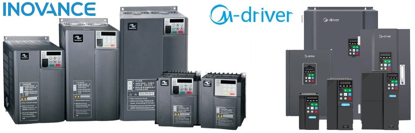
Частотные преобразователи предназначены для регулирования скорости вращения электродвигателя, в зависимости от показаний технологических параметров или схемы управления. Частотные преобразователи M-Driver и Inovance возможно настроить и запрограммировать различными способами, так как они поддерживают большое количество дискретных, релейных входов/выходов, а также аналоговые вх/вых для подключения периферийных технологических датчиков, потенциометров и т.д. С помощью встроенного аналогового выхода можно дублировать информацию о скорости вращения на внешние контроллеры и приборы. Частотные преобразователи от обоих производителей поддерживает промышленный протокол Modbus, который крайне необходим в развертывании больших систем АСУТП. С помощью данного протокола можно передавать данные: скорость вращения, текущий ток и мощность, задание для чп, наработка по времени и т.д.
Частотные преобразователи M-Driver имеют линейку с номинальной мощностью от 0.75 до 500кВт, а линейка MD310 от производителя Inovance имеет номинальную мощность от 0.4 до 18.5кВт. Разность по мощностям объясняется тем, что производитель Inovance предусмотрел другие линейки частотных преобразователей (MD290 и MD500) для более мощных двигателей. По нашему опыту большей популярностью обладают частотные преобразователи до 22кВт. Производство и сборка частотных преобразователей M-Driver и Inovance производится в Китае и данные производители являются одними из лидеров на Азиатском и Европейском рынке. Гарантийные сроки на частотные преобразователи от данных производителей составляют 18 месяцев.  Частотные преобразователи имеют компактные размеры, тем самым обеспечивая малые габариты для монтажа и снижение затрат на большие корпуса и шкафы. Производители M-Driver и Inovance обеспечивают проверку частотных преобразователей на заводе с полной нагрузкой на предельные эксплуатационные характеристики на специальных оборудованных стендах. Также частотные преобразователи серии M500 до 22кВт включительно и вся линейка MD310 до 18.5кВт включительно имеет встроенные тормозные модули, которые обеспечивают экономию денежных средств и легкое подключение тормозных резисторов. Данные линейки частотных преобразователей поддерживают: скалярное и векторное управление, функции простого ПЛК, ПИД-регулятор, несколько групп времени разгона и торможения, стабильную работу при провалах напряжения, высокую перегрузочную способность (150% в течении 60с, 180% в течении 2с). Частотные преобразователи M-Driver является более дешевым и доступным устройством нежели частотные приводы Inovance, при этом технические характеристики данных серий максимально схожи. В этом Вы можете убедиться, скачав руководство пользователя M-Driver и Inovance MD310. Настройка данных частотных преобразователей производится аналогичным образом. Отличительными свойствами между частотными преобразователями M-Driver и Inovance является то, что ЧП Inovance MD310 поддерживают платы расширения вх/вых (если штатных недостаточно, что бывает крайне редко), отдельную русскоязычную панель управления (приобретается отдельно), web сервер для удаленного мониторинга и управления (приобретается отдельно), а также некоторые технические свойства на которых мы остановимся чуть позже.
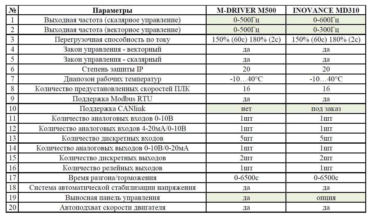 Как видно из таблицы выше, технические характеристики данных моделей частотных преобразователей отличаются незначительно и могут взаимозаменять друг друга. Частотные преобразователи Inovance присутствуют на российском рынке уже более 7 лет и хорошо себя зарекомендовали в различных отраслях и сферах применения (насосных станциях, лифтовом оборудовании, станках и т.д). Частотные преобразователи M-Driver выпускаются уже более 12 лет, но на российском рынке появились относительно недавно (2 года назад). В связи с этим и ценовая политика данных производителей сильно отличается, при относительно равных технических характеристиках и гарантийных обязательствах.
Сравнивая серии частотных преобразователей M-Driver и Inovance можно сделать некоторые выводы:
- технические характеристики частотных преобразователей максимально приближены и могут взаимозаменять друг друга
- габаритные размеры отличаются
- стоимость частотных преобразователей M-Driver значительно меньше, чем аналогичные модели Inovance
- расширенная линейка мощностей у ЧП M-Driver, чем у моделей Inovance MD310 (возможно использовать другие линейки MD290 или MD500)
- частотные преобразователи Inovance имеют дополнительные аксессуары расширяя технические возможности устройства (Web сервер, выносную панель, платы расширения). У частотных преобразователей M-Driver данные аксессуары не предусмотрены
Наша компания поставляет частотные преобразователи M-Driver и Inovance! Большие остатки популярных моделей на складах и под заказ! Если у Вас имеются технические вопросы, либо необходимо подобрать частотный преобразователь под Ваши нужды, свяжитесь с нами любым удобным для Вас способом!
Полезные ссылки:
- частотные преобразователи M-Driver M500 3-фазные | 0.75 — 500кВт
- частотные преобразователи M-Driver M500 1-фазные | 0.75 — 15кВт
- частотные преобразователи Inovance MD310 3-фазные | 0.4 — 15кВт
- частотные преобразователи Inovance MD200 1(3)-фазные | 0.4 — 3.7кВт
Руководства пользователя (инструкции):
- руководство пользователя на частотные преобразователи M-Driver
- руководство пользователя на частотные преобразователи Inovance MD310
- руководство пользователя на частотные преобразователи Inovance MD200
Читайте также
-
Contents
-
Table of Contents
-
Troubleshooting
-
Bookmarks
Quick Links
MD380L
Open Loop Elevator Drive
Quick Start Manual
V0.5
Data Code:19010299
Related Manuals for Inovance MD380L
Summary of Contents for Inovance MD380L
-
Page 1
MD380L Open Loop Elevator Drive Quick Start Manual V0.5 Data Code:19010299… -
Page 42
Inova Automation Co., Limited Address:Unit B01, 17/FMG Tower, 133 Hoi Bun Road, Kwun Tong, Hong Kong Tel: (852) 2751 6080 Fax: (852) 2751 6933 Email: info@inova-automation.com Http://www.inovance.cn…
Table of Contents
|
|

Ремонт частотного преобразователя INOVANCE, впрочем, как и ремонт частотников других производителей имеет ряд особенностей в силу своего конструктива. Частотные преобразователи, точнее их начинка делятся на две части:
- Аппаратная часть,
- Программная часть.
Частотники данного производителя не являются исключением из правил, именно поэтому ремонт частотного преобразователя INOVANCE имеет точно такой же ряд особенностей, как и у других преобразователей.
Диагностировать ту или иную неисправность помогают коды ошибок частотного преобразователя, которые отображаются на небольшом дисплее, расположенном на лицевой панели привода. Коды ошибок частотного преобразователя INOVANCE в зависимости от серии описаны в инструкции, пользователя которые можно скачать с нашего сайта.
Ремонт частотных преобразователей INOVANCE в Миассе, как и любых других преобразователей, выпущенных под другими брендами, всегда начинается с аппаратной части, после успешного ремонта аппаратной части наступает очередь программной.
Настройка частотного преобразователя INOVANCE также прописана в инструкции завода производителя, для каждой серии частотных преобразователей настройка будет индивидуальной, так как каждая линейка преобразователей решает свои собственные задачи, этим обусловливается широкая номенклатура данного промышленного оборудования.
Ремонт частотных преобразователей INOVANCE в сервисном центре

Компания «Кернел» производитремонт частотных преобразователей INOVANCE в Миассе с 2002 года. За время существования компании наши сотрудники накопили колоссальный опыт в ремонте преобразователей частоты такого известного производителя как INOVANCE. Ремонт подобного промышленного оборудования ответственное и сложное занятие, требующие максимальной отдачи, профессионализма и максимально полной материальной базе.
Специалисты нашего сервисного центра максимальное внимание уделяют качеству исполнения ремонта, программирования и настройке промышленных преобразователей частоты, не зависимо от производителя данного промышленного оборудования. Именно поэтому мы смело даем гарантию на все выполненные работы шесть месяцев.
Ремонт частотных преобразователей INOVANCE в Миассе производится исключительно с использованием оригинальных запасных частей, на компонентном уровне с применением высокотехнологичного диагностического оборудования, квалифицированным персоналом с инженерным образованием.
В случае выхода из строя преобразователя частоты на вашем производстве либо появились проблемы с приводом, которые вы не можете решить самостоятельно, мы всегда рады вам помочь. Специалисты нашего сервисного центра в минимальные сроки проведут глубокую диагностику с последующим ремонтом частотного преобразователя INOVANCE.
Инженеры сервисного центра выполняют качественный ремонт частотных преобразователей INOVANCE всех серий, когда-либо выпускаемых компанией.
| Серия ПЧ | Типы частотных преобразователей INOVANCE |
|---|---|
| INOVANCE MD200 | MD200S0.4B; MD200S0.75B; MD200S1.5B; MD200S2.2B; MD200T0.4B; MD200T0.75B; MD200T1.5B; MD200T2.2B; MD200T3.7B |
| INOVANCE MD280 | MD280NS0.4GB; MD280NS0.7 GB; MD280NS1.5 GB; MD280NS2.2 GB; MD280NT0.7 GB; MD280NT1.5 GB; MD280NT2.2 GB; MD280NT3.7GB/5.5PB; MD280NT5.5GB/7.5PB; MD280NT7.5GB/11PB; MD280NT11GB/15PB; MD280NT15GB/18.5PB; MD280NT18.5G/22P; MD280NT22G/30P; MD280NT30G/37P; MD280NT37G/45P; MD280NT45G/55P; MD280NT55G/75P; MD280NT75G/90P; MD280NT90G/110P; MD280NT110G/132P; MD280NT132G/160P; MD280NT160G/200P; MD280NT200G/220P; MD280NT220G/250P; MD280NT250G/280P; MD280NT280G/315P; MD280NT315G/355P; MD280NT355G/400P; MD280NT400G/450P |
| INOVANCE MD290 | MD290T0.4G/0.7PB; MD290T0.7G/1.1PB; MD290T1.1G/1.5PB; MD290T1.5G/2.2PB; MD290T2.2G/3.0PB; MD290T3.0G/3.7PB; MD290T3.7G/5.5PB; MD290T5.5G/7.5PB; MD290T7.5G/11PB; MD290T11G/15PB; MD290T15G/18.5PB; MD290T18.5G/22P; MD290T22G/30P; MD290T30G/37P; MD290T37G/45P; MD290T45G/55P; MD290T55G/75P; MD290T75G/90P; MD290T90G/110P; MD290T110G/132P; MD290T132G/160P; MD290T160G/200P; MD290T220P; MD290T250P; MD290T280P; MD290T315P; MD290T355P; MD290T400P; MD290T450P; MD290T500P; MD290T200G; MD290T220G; MD290T250G; MD290T280G; MD290T315G; MD290T355G; MD290T400G; MD290T450G |
| INOVANCE MD310 | MD310T0.4B; MD310T0.7B; MD310T1.5B; MD310T2.2B; MD310T3.7B; MD310T5.5B; MD310T7.5B; MD310T11B; MD310T15B; MD310T18.5B |
| INOVANCE MD380 | MDBUN; MDFB; MDRU; MD38IO1; MD38IO2; MD38TX1; MD38CAN1; MD38CAN2; MD38DP; MD38PC1; MD38PG1; MD38PG3; MD38PG4; MD38PG5; MDKE; MDKE4; MDCAB |
| INOVANCE MD500 | MD500T0.4GB; MD500T0.7GB; MD500T1.1GB; MD500T1.5GB; MD500T2.2GB; MD500T3.0GB; MD500T3.7GB; MD500T5.5GB; MD500T7.5GB; MD500T11GB; MD500T15GB; MD500T18.5GB; MD500T22GB; MD500T30GB; MD500T37GB; MD500T45GB; MD500T55GB; MD500T75GB; MD500T90G; MD500T110G; MD500T132G; MD500T160G; MD500T200G; MD500T220G; MD500T250G; MD500T280G; MD500T315G; MD500T355G; MD500T400G; MD500T450G |
| INOVANCE MD800 | MD800-1-4T1R8; MD800-1-4T3R4; MD800-1-4T4R8; MD800-1-4T5R5; MD800-1-4T9R5; MD800-1-4T13; MD800-1-4T17; MD800-1-4T1R8S; MD800-1-4T3R4S; MD800-1-4T4R8S; MD800-1-4T5R5S; MD800-1-4T9R5S; MD800-1-4T13S; MD800-1-4T17S; MD800-1-2T1R7; MD800-1-2T3; MD800-1-2T5; MD800-1-2T8; MD800-1-2T11; MD800-1-2T1R7S; MD800-1-2T3S; MD800-1-2T5S; MD800-1-2T8S; MD800-1-2T11S; MD800-0-4T12; MD800-0-4T22; MD800-0-4T41; MD800-0-4T12B; MD800-0-4T22B; MD800-0-4T41B; MD800-0-2S24; MD800-0-2S40; MD800-0-2S24B; MD800-0-2S40B |
| INOVANCE CS710 | CS7104T0.4GB; CS7104T0.7GB; CS7104T1.1GB; CS7104T1.5GB; CS7104T2.2GB; CS7104T3.0GB; CS7104T3.7GB; CS7104T5.5GB; CS7104T7.5GB; CS7104T11GB; CS7104T15GB; CS7104T18.5G; CS7104T22GB; CS7104T30GB; CS71040T37GB; CS7104T45GB; CS7104T55GB; CS7104T75GB; CS7104T90G; CS7104T110G; CS7104T132G; CS7104T160G; CS7104T200G; CS7104T220G; CS7104T250G; CS7104T280G; CS7104T315G; CS7104T355G; CS7104T400G; CS7104T450G; CS7104T200G-L; CS7104T220G-L; CS7104T250G-L; CS7104T280G-L; CS7104T315G-L; CS7104T355G-L; CS7104T400G-L; CS7104T450G-L |
В данной таблице присутствуют далеко не все частотные преобразователи INOVANCE ремонт которых предлагает наш сервисный центр.
Ошибки частотного преобразователя INOVANCE

В процессе работы выходит из строя даже самое надежное промышленное оборудование. Частотники в наше время, нашли широкое применение абсолютно во всех сферах промышленности, управляя как мини моторами в оргтехнике, так и гигантскими двигателями в горнодобывающей промышленности.
Для простоты общения со столь сложной электроникой все частотные преобразователи оснащены небольшими дисплеями с помощью которых выводятся информационные сообщения с кодами ошибок, расшифровав которые можно сразу же узнать причину ее возникновения. Если учесть распространенность данной промышленной электроники, то появляется острая нужда в расшифровке кодов ошибок частотных преобразователей. В этой статье мы рассмотрим одного из самых известных производителей промышленной электроники имеющему уважение во всем мире, INOVANCE и серию сервоприводов MD500.
Существует несколько видов ошибок, некоторые из них можно устранить автоматически, а некоторые возможно исправить только, обратившись в специализированный сервисный центр. В руководстве пользователя прописаны все коды ошибок частотного преобразователя INOVANCE и их расшифровка.
Коды ошибок частотного преобразователя INOVANCE MD500
| Код ошибки | Ошибка |
|---|---|
| Err02 | Максимальный ток во время разгона. |
| Err03 | Максимальный ток во время торможения. |
| Err04 | Максимальный ток при постоянной скорости. |
| Err05 | Перенапряжение во время разгона. |
| Err06 | Перенапряжение во время торможения. |
| Err07 | Перенапряжение при постоянной скорости. |
| Err08 | Неисправность зарядного сопротивления. |
| Err09 | Минимальное напряжение. |
| Err10 | Перегрузка привода. |
| Err11 | Перегрузка двигателя. |
| Err12 | Входная фаза потеряна. |
| Err13 | Выходная фаза потеряна. |
| Err14 | Перегрев IGBT модуля. |
| Err15 | Внешняя ошибка. |
| Err16 | Ошибка связи. |
| Err17 | Неисправность контактора. |
| Err18 | Ошибка измерения тока. |
| Err19 | Ошибка авто-настройки двигателя. |
| Err20 | Ошибка энкодера. |
| Err21 | Ошибка чтения-записи EEPROM. |
| Err23 | Короткое замыкание на землю. |
| Err26 | Время работы достигло предела. |
| Err27 | Ошибка 1, задаваемая пользователем. |
| Err28 | Ошибка 2, задаваемая пользователем. |
| Err29 | Время включения достигло предела. |
| Err30 | Нагрузка потеряна. |
| Err31 | Обратная связь ПИД потеряна во время работы. |
| Err40 | Ограничение поимпульсного тока. |
| Err41 | Переключение между двигателями во время работы. |
| Err42 | Ошибка по скорости. |
| Err43 | Превышение скорости двигателя. |
| Err45 | Превышение температуры двигателя. |
| Err61 | Перегрузка тормозного блока или резистора. |
| Err62 | Короткое замыкание в цепи тормозного резистора. |
Документация
|
Руководство по эксплуатации преобразователя частоты INOVANCE MD200 |
 Скачать PDF Скачать PDF |
|
Руководство по эксплуатации преобразователей частоты INOVANCE MD280 |
Скачать PDF |
|
Руководство по эксплуатации преобразователей частоты INOVANCE MD290 |
Скачать PDF |
|
Руководство по эксплуатации преобразователей частоты INOVANCE MD310 |
Скачать PDF |
|
Руководство по эксплуатации преобразователей частоты INOVANCE MD380 |
Скачать PDF |
|
Руководство по эксплуатации преобразователей частоты INOVANCE MD500 |
Скачать PDF |
|
Руководство по эксплуатации преобразователей частоты INOVANCE CS710 |
Скачать PDF |
Схемы подключения частотных преобразователей INOVANCE
| Схема подключения преобразователей частоты INOVANCE MD200XXX | Схема подключения преобразователей частоты INOVANCE MD200XXX-NC |
|
|

|
| Схема подключения преобразователей частоты INOVANCE MD310 | Схема подключения преобразователей частоты INOVANCE MD380 |

|

|
| Схема подключения преобразователей частоты INOVANCE MD500 | |
|
|


Для максимально долгой и безаворийной работы частотных преобразователей важно неукоснительно соблюдать все, что прописано в документации.
Обязательно должны соблюдаться все рекомендации, изложенные в инструкции по монтажу и эксплуатации, в особенности требования по технике безопасности!
Преобразователь частоты разработан таким образом, что он пытается избежать аварийных отключений путем ограничения момента, перенапряжения и т.п.
Появление сбоев при вводе в эксплуатацию или вскоре после него обычно свидетельствует о неверной настройке или неправильном подключении.
Возникновение неисправностей или проблем после длительного режима бесперебойной работы обычно происходит по причине изменений в системе или ее окружении (например, в результате износа).
Дополнительную информацию по частотным преобразователям INOVANCE можно посмотреть и скачать на офсайте.
Настройка частотного преобразователя INOVANCE, программирование

Настройка частотных преобразователей INOVANCE (программирование) происходит в рамках установленных производителем правил, существует общий алгоритм по программированию (настройке частотных преобразователей), относящийся ко всем производителям данного промышленного оборудования. Ниже представлена пошаговая инструкция по настройке частотных преобразователей INOVANCE.
- Выбор режима управления приводом INOVANCE (управление по показанию датчиков, дистанционное управление, дистанционное управление).
- В случае использования отдельного (выносного) монитора, настраивается вывод на него технической информации.
- Далее определяем конфигурацию подключения серводвигателя. На данной стадии задаются такие параметры как- возможность применения обратной связи либо без ее применения, а в память блока заносятся данные по: величине крутящего момента, мощности потребителей, номинальное значения частоты, напряжение, ток и скорости вращения ротора.

- Программируется минимально допустимая величина напряжения и частоты, а также время ускорения ротора от ноля до номинального значения.
- И в завершении, в программу управления частотным преобразователем INOVANCE вносятся функциональные данные со значениями отдельных клемм и особенностями сигналов. Отмечаются действия оборудования, выполняющиеся автоматически при отсутствии информации поступающей в оперативном режиме с датчика.

В некоторых частотниках существует пункт наличия/отсутствия фильтра в цепи питания двигателя. Этот пункт отвечает за подключение различных видов нагрузок, в том случае, когда возможно выбрать нормальное или инверсное изменение частоты при повышении уровня сигнала обратной связи.
Все настройки частотных преобразователей INOVANCE приведены в технической документации к частотному преобразователю который можно скачать на свой компьютер, распечатать или просто открыть на официальном сайте INOVANCE.
Оставить заявку на ремонт частотных преобразователей INOVANCE
У вас вышел из строя частотник? Вам необходим срочный ремонт частотных преобразователей INOVANCE в Миассе? Оставьте заявку на ремонт нажав на одноименную кнопку в верхней правой части экрана либо свяжитесь с нашими менеджерами. Связаться с ними можно несколькими способами:

- Заказав обратный звонок (кнопка в правом нижнем углу сайта)
- Посредством чата (кнопка расположена с левой стороны сайта)
- Позвонив по номеру телефона:
- +7(8482) 79-78-54;
- +7(8482) 55-96-39;
- +7(917) 121-53-01
- Написав на электронную почту: 89171215301@mail.ru
Далеко не полный список производителей промышленной электроники и оборудования, ремонтируемой в нашей компании.
- В начало статьи
Specifications:
|
Accompanying Data:
Inovance MD380L DC Drives PDF Quick Start Manual (Updated: Saturday 28th of January 2023 06:45:44 AM)
Rating: 4.3 (rated by 22 users)
Compatible devices: IS620N Series, MD800 Series, CP700 Series, MD320 Series, AM600 Series, MD810 Series, MD380 Series, MD290 Series.
Recommended Documentation:
Inovance MD380L: Text of Quick Start Manual
(Ocr-Read Version Summary of Contents, UPD: 28 January 2023)
-
22, 19 CONTINUE Para. Parameter name Default Commissioning Set DO function F5- 01 FM function selection 2 2(Fault output) 0 : No output 1 : AC Drive running 2 : Fault output 36: Software current exceeding limit 42 : Brake output 43 : MC (Magnetic contactor) output Setting range:0 to 59; NOTE: this signal goes to ma…
-
25, 22 This function can work by assigning IGBT Enable function to a digital input, please refer to the table below to set. Take DI6 for example: assign IGBT Enable to DI6, then set F4-05=8necessary to change active mode of IGBT Enable, then use F4-38 or F4-39 to set (low level or high level active). Function Code Parameter Name Setting Range Unit Default Commission F…
-
34, 31 5.9 Group F8: auxiliary functions Function Code Parameter Name Setting Range Unit Default Commission F8-04 Deceleration time 2 0.0 to 6500.0 sec 2.0 F8-26 Frequency switchover point between deceleration time 1 and deceleration time 2 0.00 to maximum frequency Hz 0.00 F8-55 Brake release current threshold 0 to 200 % 5 F8-56 Br…
-
20, 17 CONTINUE Para. Parameter name Default Commissioning Select command source F0- 02 Command source selection 1 0 Perform motor auto tuning F1- 37 Auto-tuning selection 0 3 0: No auto-tuning 2: Asynchronous motor dynamic auto-tuning 3: Asynchronous motor static auto-tuning(NEW) NOTE …
-
40, 37 6.2 Inverter common symptoms and diagnostics Fault Name Possible Causes Solutions There is no display at power-on. 1. There is no power supply or the power supply is too low. 2. The switching power supply on the drive board is faulty. 3. The rectifier bridge is damaged. 4. The buffer resistor of the drive is damaged. 5. The control board or the keypad is faulty. 6. The …
-
7, 4 2.2 Typical wiring 2 (use analog input as frequency reference) (Set F0-03=2 to use AI1) NOTE: Extension I/O card MD38IO1 applies to the drive 3.7 kW and above only. Extension I/O card MD38IO1 DI5 DI4 DI3 DI2 DI1 OP +10V A I 2 GND A I 1 W Inverter O utput Contactor V U PB 1 …
-
6, 3 2 Wiring 2.1 Typical wiring 1 (use multi-reference input as frequency reference) (Default: F0-03=6, use multi-reference) NOTE: Extension I/O card MD38IO1 applies to the drive 3.7 kW and above only. Extension I/O card MD38IO1 DI5 DI4 DI3 DI2 DI1 OP +10V A I 2 GND AI1 W Inverter O utput Contactor V …
-
29, 26 5.4 Group F3: VF control Function code Parameter Name Setting Range Unit Default Commission F3-00 V/F curve setting 0: Linear V/F 1: Multi-point V/F 2 to 11: not relevant settings N.A. 0 F3-01 Torque boost 0.0 to 30.0 (if it is 0, then auto torque boost is activated) % 0 F3-02 Cut- off frequency of torque boost 0.00 to max …
-
1, MD380L Open Loop Elevator Drive Quick Start Manual MD380L Open Loop Elevator Drive Quick Start Manual V0.5 Data Code:19010299 Inova Automation Co., Limited Address:Unit B01, 17/FMG Tower, 133 Hoi Bun Road, Kwun Tong, Hong Kong Tel: (852) 2751 6080 Fax: (852) 2751 6933 Email: [email protected] Http://www.inovance.cn
… -
32, 29 5.6 Group F5: output terminals Function Code Parameter name Setting Range Unit Default Commission F5-00 FM terminal output mode 0 : High-speed pulse output (FMP) 1 : ON/OFF output (FMR) N.A 1 F5-01 FMR function (open-collector output terminal) Attention! Set F5-00 = 1 when FM is used as MC or Brake output. 0 …
-
12, 9 3 Operation panel 3.1 Get familiar with operation panel Overview RUNLOCAL/REMOTFED/REVTUNE/TC RPM % A V Hz PRGENTER RUN STOP RES MF.K QUICK Command source indicator ON: terminal; OFF: operation panel; BLINK: communication. Running direction indicator ON: reverse; OFF: forward Running state indicator ON: running; OFF:stop. LED display for parameters Program key Menu mode sel…
-
35, 32 Function Code Parameter Name Setting Range Unit Default Commission F9 — 20 Input terminal status upon 3rd fault N.A. N.A. N.A. F9 — 21 Output terminal status upon 3rd fault N.A. N.A. N.A. F9 — 22 AC drive status upon 3rd fault N.A. N.A. N.A. F9 — 23 Power- on time upon 3rd fault N.A. N.A. N.A. …
-
15, 12 4 Quick setup 4.1 Complete timing diagram for normal travel (use multi-reference as frequency reference) DI Enable (If provide) ON OFF DI 1 Travel UP ON OFF …
Inovance MD380L: Recommended Instructions
Sophia Series 3, Ex-PMR 2000, StorageWorks b2000 — NAS, N546-20M, rMB81-001


-
STANDARDS CONFORMITY An ACS2250 fitted with this Option complies with the Following standards: CE-marked for Low Voltage Directive. IEC 664-1 Insulation Coordination within Low Voltage Systems. UL 840 Insulation Coordination for electrical equipment. EN50081-2 EMC Generic Emissions Standard, Industrial Level. EN50082-2 EMC Generic Immunity Standard, Indus …
ACS250 2
-
de BeschreibungSTOen DescriptionSTOes DescripciónSTOfr DescriptionSTOit DescrizioneSTOzh STOSafe torque off (STO)80399721603[8039936]Integrierter AntriebIntegrated DriveEMCA-EC-67-… …
EMCA-EC-67 CO Series 118
-
SINUMERIK 840D sl/840Di sl/840D/840Di/810D Job planning ________________________________________________________________________________________________________________________________________________________________________________________________________________________________ Preface Flexible NC programming 1Subroutines, Macros 2File and Program Management 3Protection zones …
SINUMERIK 840D sl 687
-
Kinco®Stepper Driver 2CM0870User manual V1.0Kinco Electric(Shenzhen) Ltd.To be the partner of your successKinco Electric (Shenzhen) Ltd.Building 1, No.6 Langshan 1st Rd, Hi-tech ParkNorth, Nanshan, Shenzhen, China. (518057)http://[email protected] Safety PrecautionsObserve safety precautions strictly. Use a multi-meter to verify that the vo …
2CM0870 2
-
MECHATRONIC DRIVE WITH STEPPER MOTOR PANdrive TRINAMIC Motion Control GmbH & Co. KG Hamburg, Germany www.trinamic.com Hardware Version V1.2 HARDWARE MANUAL + + PD-1140 + + UNIQUE FEATURES: Stepper Motor with Controller / Driver 0.22 — 0.70 Nm / 24 V DC sensOstep™ Encoder USB, RS485, and CAN …
PANdrive PD-1140 26
-
Divisione S.B.C. LVD ( LVD1, LVD2, LVD5, LVD10, LVD15 ) User’s Manual Rev. 1.7 November 2002 (Software Rel. 55) …
LVD1 99
-
INSTALLATION MANUALPENTEK INTELLIDRIVE™PID2000-1123www.onga.com.au©2010 PNX900 (Rev. 9/14/10)Installation/Operation/PartsFor further operating, installation, or maintenance assistance: Call 1-300-137-344 …
PENTEK INTELLIDRIVE PID2000-1123 16
-
Step By Step GuideHVAC Drive H300 Frame sizes 3 to 12www.controltechniques.com/supportDESeite 2Diese Anleitung bietet Informationen für eine schnelle Inbetrieb …
H300 47
Popular Right Now:
Operating Impressions, Questions and Answers:
Каталоги, Инструкции, Программное обеспечение
Инструкции по эксплуатации Inovance
Описания по HMI-панелям Inovance
ПЛК, HMI, BUS — контроллеры Inovance
Модули ввода-вывода (IO modules) Inovance
Описание Ethercat устройств для подгрузки в CoDesys для продукции Inovace
Программное обеспечение
Программное обеспечение для настройки AMAC контроллеров — InoProShop V1
(Архив, zip, 853 Мб)
Inovance MD380L DC Drives PDF User Guides and Manuals for Free Download: Found (1) Manuals for Inovance MD380L Device Model (Quick Start Manual)
More DC Drives Device Models:
-
Invertek Drives
OPTISTICK 2
OPTISTICK User Guide OPTISTICK 2 For fast and accurate repeat drive programming Compatibility: This Option is suitable for use on the following product ranges: ODE-2 Drives ODP-2 Drives ODE-3 Drives ODV-2 Drives Note: Parameters can only be copied between drives of the same product range and power rati …
OPTISTICK 2 DC Drives, 2
-
BIAX
MB 20/2
Originalbetriebsanleitung Translation of the original operating manual Traduction du manuel de service original Antriebsmaschinen für biegsame Wellen Drive units for flexible shafts Machines d’entraînement pour arbres flexibles MB 20/2 MB 20/3 G MB 20/3 MB 30 E Diese Anleitung muss dem Anwender (Werker) au …
MB 20/2 DC Drives, 34
-
GE
AF-650 GP
The instructions do not purport to cover all details or variations in equipment nor to provide for every possible contingency to be met in connection with installation, operation or maintenance. Should further information be desired or should particular problems arise which are not covered suciently for the purchase …
AF-650 GP DC Drives, 155
-
TIME LED
781234
Installation and Operating InstructionsINS-781234-V1Read and follow instructions before operating your driver.Save this manual for future reference.Package includes:1 x Ambient 40W LED 12V Driver1 x Manual TIME LED is part of Pitacs Limited. For customer support contact:Bradbourne Point, Bradbourne Drive, Tilbrook, Mi …
781234 DC Drives, 2
Recommended Documentation:
|
|
Ремонт частотных преобразователей INOVANCE
Ремонт частотного преобразователя INOVANCE, впрочем, как и ремонт частотников других производителей имеет ряд особенностей в силу своего конструктива. Частотные преобразователи, точнее их начинка делятся на две части:
- Аппаратная часть,
- Программная часть.
Частотники данного производителя не являются исключением из правил, именно поэтому ремонт частотного преобразователя INOVANCE имеет точно такой же ряд особенностей, как и у других преобразователей.
Диагностировать ту или иную неисправность помогают коды ошибок частотного преобразователя, которые отображаются на небольшом дисплее, расположенном на лицевой панели привода. Коды ошибок частотного преобразователя INOVANCE в зависимости от серии описаны в инструкции, пользователя которые можно скачать с нашего сайта.
Ремонт частотных преобразователей INOVANCE в Миассе, как и любых других преобразователей, выпущенных под другими брендами, всегда начинается с аппаратной части, после успешного ремонта аппаратной части наступает очередь программной.
Настройка частотного преобразователя INOVANCE также прописана в инструкции завода производителя, для каждой серии частотных преобразователей настройка будет индивидуальной, так как каждая линейка преобразователей решает свои собственные задачи, этим обусловливается широкая номенклатура данного промышленного оборудования.
Ремонт частотных преобразователей INOVANCE в сервисном центре
Компания «Кернел» производитремонт частотных преобразователей INOVANCE в Миассе с 2002 года. За время существования компании наши сотрудники накопили колоссальный опыт в ремонте преобразователей частоты такого известного производителя как INOVANCE. Ремонт подобного промышленного оборудования ответственное и сложное занятие, требующие максимальной отдачи, профессионализма и максимально полной материальной базе.
Специалисты нашего сервисного центра максимальное внимание уделяют качеству исполнения ремонта, программирования и настройке промышленных преобразователей частоты, не зависимо от производителя данного промышленного оборудования. Именно поэтому мы смело даем гарантию на все выполненные работы шесть месяцев.
Ремонт частотных преобразователей INOVANCE в Миассе производится исключительно с использованием оригинальных запасных частей, на компонентном уровне с применением высокотехнологичного диагностического оборудования, квалифицированным персоналом с инженерным образованием.
В случае выхода из строя преобразователя частоты на вашем производстве либо появились проблемы с приводом, которые вы не можете решить самостоятельно, мы всегда рады вам помочь. Специалисты нашего сервисного центра в минимальные сроки проведут глубокую диагностику с последующим ремонтом частотного преобразователя INOVANCE.
Инженеры сервисного центра выполняют качественный ремонт частотных преобразователей INOVANCE всех серий, когда-либо выпускаемых компанией.
| Серия ПЧ | Типы частотных преобразователей INOVANCE |
|---|---|
| INOVANCE MD200 | MD200S0.4B; MD200S0.75B; MD200S1.5B; MD200S2.2B; MD200T0.4B; MD200T0.75B; MD200T1.5B; MD200T2.2B; MD200T3.7B |
| INOVANCE MD280 | MD280NS0.4GB; MD280NS0.7 GB; MD280NS1.5 GB; MD280NS2.2 GB; MD280NT0.7 GB; MD280NT1.5 GB; MD280NT2.2 GB; MD280NT3.7GB/5.5PB; MD280NT5.5GB/7.5PB; MD280NT7.5GB/11PB; MD280NT11GB/15PB; MD280NT15GB/18.5PB; MD280NT18.5G/22P; MD280NT22G/30P; MD280NT30G/37P; MD280NT37G/45P; MD280NT45G/55P; MD280NT55G/75P; MD280NT75G/90P; MD280NT90G/110P; MD280NT110G/132P; MD280NT132G/160P; MD280NT160G/200P; MD280NT200G/220P; MD280NT220G/250P; MD280NT250G/280P; MD280NT280G/315P; MD280NT315G/355P; MD280NT355G/400P; MD280NT400G/450P |
| INOVANCE MD290 | MD290T0.4G/0.7PB; MD290T0.7G/1.1PB; MD290T1.1G/1.5PB; MD290T1.5G/2.2PB; MD290T2.2G/3.0PB; MD290T3.0G/3.7PB; MD290T3.7G/5.5PB; MD290T5.5G/7.5PB; MD290T7.5G/11PB; MD290T11G/15PB; MD290T15G/18.5PB; MD290T18.5G/22P; MD290T22G/30P; MD290T30G/37P; MD290T37G/45P; MD290T45G/55P; MD290T55G/75P; MD290T75G/90P; MD290T90G/110P; MD290T110G/132P; MD290T132G/160P; MD290T160G/200P; MD290T220P; MD290T250P; MD290T280P; MD290T315P; MD290T355P; MD290T400P; MD290T450P; MD290T500P; MD290T200G; MD290T220G; MD290T250G; MD290T280G; MD290T315G; MD290T355G; MD290T400G; MD290T450G |
| INOVANCE MD310 | MD310T0.4B; MD310T0.7B; MD310T1.5B; MD310T2.2B; MD310T3.7B; MD310T5.5B; MD310T7.5B; MD310T11B; MD310T15B; MD310T18.5B |
| INOVANCE MD380 | MDBUN; MDFB; MDRU; MD38IO1; MD38IO2; MD38TX1; MD38CAN1; MD38CAN2; MD38DP; MD38PC1; MD38PG1; MD38PG3; MD38PG4; MD38PG5; MDKE; MDKE4; MDCAB |
| INOVANCE MD500 | MD500T0.4GB; MD500T0.7GB; MD500T1.1GB; MD500T1.5GB; MD500T2.2GB; MD500T3.0GB; MD500T3.7GB; MD500T5.5GB; MD500T7.5GB; MD500T11GB; MD500T15GB; MD500T18.5GB; MD500T22GB; MD500T30GB; MD500T37GB; MD500T45GB; MD500T55GB; MD500T75GB; MD500T90G; MD500T110G; MD500T132G; MD500T160G; MD500T200G; MD500T220G; MD500T250G; MD500T280G; MD500T315G; MD500T355G; MD500T400G; MD500T450G |
| INOVANCE MD800 | MD800-1-4T1R8; MD800-1-4T3R4; MD800-1-4T4R8; MD800-1-4T5R5; MD800-1-4T9R5; MD800-1-4T13; MD800-1-4T17; MD800-1-4T1R8S; MD800-1-4T3R4S; MD800-1-4T4R8S; MD800-1-4T5R5S; MD800-1-4T9R5S; MD800-1-4T13S; MD800-1-4T17S; MD800-1-2T1R7; MD800-1-2T3; MD800-1-2T5; MD800-1-2T8; MD800-1-2T11; MD800-1-2T1R7S; MD800-1-2T3S; MD800-1-2T5S; MD800-1-2T8S; MD800-1-2T11S; MD800-0-4T12; MD800-0-4T22; MD800-0-4T41; MD800-0-4T12B; MD800-0-4T22B; MD800-0-4T41B; MD800-0-2S24; MD800-0-2S40; MD800-0-2S24B; MD800-0-2S40B |
| INOVANCE CS710 | CS7104T0.4GB; CS7104T0.7GB; CS7104T1.1GB; CS7104T1.5GB; CS7104T2.2GB; CS7104T3.0GB; CS7104T3.7GB; CS7104T5.5GB; CS7104T7.5GB; CS7104T11GB; CS7104T15GB; CS7104T18.5G; CS7104T22GB; CS7104T30GB; CS71040T37GB; CS7104T45GB; CS7104T55GB; CS7104T75GB; CS7104T90G; CS7104T110G; CS7104T132G; CS7104T160G; CS7104T200G; CS7104T220G; CS7104T250G; CS7104T280G; CS7104T315G; CS7104T355G; CS7104T400G; CS7104T450G; CS7104T200G-L; CS7104T220G-L; CS7104T250G-L; CS7104T280G-L; CS7104T315G-L; CS7104T355G-L; CS7104T400G-L; CS7104T450G-L |
В данной таблице присутствуют далеко не все частотные преобразователи INOVANCE ремонт которых предлагает наш сервисный центр.
Ошибки частотного преобразователя INOVANCE
В процессе работы выходит из строя даже самое надежное промышленное оборудование. Частотники в наше время, нашли широкое применение абсолютно во всех сферах промышленности, управляя как мини моторами в оргтехнике, так и гигантскими двигателями в горнодобывающей промышленности.
Для простоты общения со столь сложной электроникой все частотные преобразователи оснащены небольшими дисплеями с помощью которых выводятся информационные сообщения с кодами ошибок, расшифровав которые можно сразу же узнать причину ее возникновения. Если учесть распространенность данной промышленной электроники, то появляется острая нужда в расшифровке кодов ошибок частотных преобразователей. В этой статье мы рассмотрим одного из самых известных производителей промышленной электроники имеющему уважение во всем мире, INOVANCE и серию сервоприводов MD500.
Существует несколько видов ошибок, некоторые из них можно устранить автоматически, а некоторые возможно исправить только, обратившись в специализированный сервисный центр. В руководстве пользователя прописаны все коды ошибок частотного преобразователя INOVANCE и их расшифровка.
Коды ошибок частотного преобразователя INOVANCE MD500
| Код ошибки | Ошибка |
|---|---|
| Err02 | Максимальный ток во время разгона. |
| Err03 | Максимальный ток во время торможения. |
| Err04 | Максимальный ток при постоянной скорости. |
| Err05 | Перенапряжение во время разгона. |
| Err06 | Перенапряжение во время торможения. |
| Err07 | Перенапряжение при постоянной скорости. |
| Err08 | Неисправность зарядного сопротивления. |
| Err09 | Минимальное напряжение. |
| Err10 | Перегрузка привода. |
| Err11 | Перегрузка двигателя. |
| Err12 | Входная фаза потеряна. |
| Err13 | Выходная фаза потеряна. |
| Err14 | Перегрев IGBT модуля. |
| Err15 | Внешняя ошибка. |
| Err16 | Ошибка связи. |
| Err17 | Неисправность контактора. |
| Err18 | Ошибка измерения тока. |
| Err19 | Ошибка авто-настройки двигателя. |
| Err20 | Ошибка энкодера. |
| Err21 | Ошибка чтения-записи EEPROM. |
| Err23 | Короткое замыкание на землю. |
| Err26 | Время работы достигло предела. |
| Err27 | Ошибка 1, задаваемая пользователем. |
| Err28 | Ошибка 2, задаваемая пользователем. |
| Err29 | Время включения достигло предела. |
| Err30 | Нагрузка потеряна. |
| Err31 | Обратная связь ПИД потеряна во время работы. |
| Err40 | Ограничение поимпульсного тока. |
| Err41 | Переключение между двигателями во время работы. |
| Err42 | Ошибка по скорости. |
| Err43 | Превышение скорости двигателя. |
| Err45 | Превышение температуры двигателя. |
| Err61 | Перегрузка тормозного блока или резистора. |
| Err62 | Короткое замыкание в цепи тормозного резистора. |
Документация
|
Руководство по эксплуатации преобразователя частоты INOVANCE MD200 |
Скачать PDF |
|
Руководство по эксплуатации преобразователей частоты INOVANCE MD280 |
Скачать PDF |
|
Руководство по эксплуатации преобразователей частоты INOVANCE MD290 |
Скачать PDF |
|
Руководство по эксплуатации преобразователей частоты INOVANCE MD310 |
Скачать PDF |
|
Руководство по эксплуатации преобразователей частоты INOVANCE MD380 |
Скачать PDF |
|
Руководство по эксплуатации преобразователей частоты INOVANCE MD500 |
Скачать PDF |
|
Руководство по эксплуатации преобразователей частоты INOVANCE CS710 |
Скачать PDF |
Схемы подключения частотных преобразователей INOVANCE
| Схема подключения преобразователей частоты INOVANCE MD200XXX | Схема подключения преобразователей частоты INOVANCE MD200XXX-NC |
|
|
|
| Схема подключения преобразователей частоты INOVANCE MD310 | Схема подключения преобразователей частоты INOVANCE MD380 |
|
|
|
| Схема подключения преобразователей частоты INOVANCE MD500 | |
|
|
Для максимально долгой и безаворийной работы частотных преобразователей важно неукоснительно соблюдать все, что прописано в документации.
Обязательно должны соблюдаться все рекомендации, изложенные в инструкции по монтажу и эксплуатации, в особенности требования по технике безопасности!
Преобразователь частоты разработан таким образом, что он пытается избежать аварийных отключений путем ограничения момента, перенапряжения и т.п.
Появление сбоев при вводе в эксплуатацию или вскоре после него обычно свидетельствует о неверной настройке или неправильном подключении.
Возникновение неисправностей или проблем после длительного режима бесперебойной работы обычно происходит по причине изменений в системе или ее окружении (например, в результате износа).
Дополнительную информацию по частотным преобразователям INOVANCE можно посмотреть и скачать на офсайте.
Настройка частотного преобразователя INOVANCE, программирование
Настройка частотных преобразователей INOVANCE (программирование) происходит в рамках установленных производителем правил, существует общий алгоритм по программированию (настройке частотных преобразователей), относящийся ко всем производителям данного промышленного оборудования. Ниже представлена пошаговая инструкция по настройке частотных преобразователей INOVANCE.
- Выбор режима управления приводом INOVANCE (управление по показанию датчиков, дистанционное управление, дистанционное управление).
- В случае использования отдельного (выносного) монитора, настраивается вывод на него технической информации.
- Далее определяем конфигурацию подключения серводвигателя. На данной стадии задаются такие параметры как- возможность применения обратной связи либо без ее применения, а в память блока заносятся данные по: величине крутящего момента, мощности потребителей, номинальное значения частоты, напряжение, ток и скорости вращения ротора.
- Программируется минимально допустимая величина напряжения и частоты, а также время ускорения ротора от ноля до номинального значения.
- И в завершении, в программу управления частотным преобразователем INOVANCE вносятся функциональные данные со значениями отдельных клемм и особенностями сигналов. Отмечаются действия оборудования, выполняющиеся автоматически при отсутствии информации поступающей в оперативном режиме с датчика.
В некоторых частотниках существует пункт наличия/отсутствия фильтра в цепи питания двигателя. Этот пункт отвечает за подключение различных видов нагрузок, в том случае, когда возможно выбрать нормальное или инверсное изменение частоты при повышении уровня сигнала обратной связи.
Все настройки частотных преобразователей INOVANCE приведены в технической документации к частотному преобразователю который можно скачать на свой компьютер, распечатать или просто открыть на официальном сайте INOVANCE.
Оставить заявку на ремонт частотных преобразователей INOVANCE
У вас вышел из строя частотник? Вам необходим срочный ремонт частотных преобразователей INOVANCE в Миассе? Оставьте заявку на ремонт нажав на одноименную кнопку в верхней правой части экрана либо свяжитесь с нашими менеджерами. Связаться с ними можно несколькими способами:
- Заказав обратный звонок (кнопка в правом нижнем углу сайта)
- Посредством чата (кнопка расположена с левой стороны сайта)
- Позвонив по номеру телефона:
- +7(8482) 79-78-54;
- +7(8482) 55-96-39;
- +7(917) 121-53-01
- Написав на электронную почту: 89171215301@mail.ru
Далеко не полный список производителей промышленной электроники и оборудования, ремонтируемой в нашей компании.
- В начало статьи