-
Page 1
Experion C300 Controller User’s Guide EP-DCX464 R301.1 11/06… -
Page 2
In no event is Honeywell liable to anyone for any indirect, special or consequential damages. The information and specifications in this document are subject to change without notice. -
Page 3
The following list identifies all documents that may be sources of reference for material discussed in this publication. Document Title Contacts World Wide Web The following Honeywell web sites may be of interest to Process Solutions customers. Honeywell Organization WWW Address (URL) Corporate http://www.honeywell.com Honeywell Process Solutions http://hpsweb.honeywell.com… -
Page 4
Republic of China China Singapore Honeywell Global TAC — +65-6580-3500 South East Asia Taiwan Honeywell Global TAC — +886-7-323-5900 Taiwan +81-3-5440-1303 Japan Honeywell Global TAC — Japan Elsewhere Call your nearest Honeywell office. Experion C300 Controller User’s Guide R301.1 Honeywell 11/06… -
Page 5
WARNING symbol on the equipment refers the user to the product manual for additional information. The symbol appears next to required information in the manual. R301.1 Experion C300 Controller User’s Guide 11/06 Honeywell… -
Page 6
Chassis Ground: Identifies a connection to the chassis or frame of the equipment shall be bonded to Protective Earth at the source of supply in accordance with national and local electrical code requirements. Experion C300 Controller User’s Guide R301.1 Honeywell 11/06… -
Page 7: Table Of Contents
C300 Peer communication with Experion nodes…………..16 C300 connections with Rockwell PLC devices…………..17 C300 connections to the Control Firewall…………….17 C300 CONTROLLER INSTALLATION AND UPGRADES ….19 Pre-installation considerations …………….19 Installation declarations………………….19 Series C control hardware installation requirements …………20 R301.1 Experion C300 Controller User’s Guide 11/06 Honeywell…
-
Page 8
To convert a redundant C300 Controller to a non-redundant controller ……51 Configure IOLINK function blocks…………….52 To configure IOLINK blocks ………………..53 Import/export C300 Controller configuration …………55 Reset Device Index and IP address of a controller ……….55 viii Experion C300 Controller User’s Guide R301.1 Honeywell 11/06… -
Page 9
CEEC300 Function Block ………………106 Main Tab ……………………..106 Peer Configuration tab …………………..109 Statistics tab……………………110 CPU Loading Tab…………………..114 CPU Overruns tab………………….114 Memory tab ……………………115 Peer Communications tab ………………..117 Display Communications tab………………..118 Block Types Info tab………………….119 R301.1 Experion C300 Controller User’s Guide 11/06 Honeywell… -
Page 10
Loading CEEC300………………….151 To load a CEEC300 block ………………..151 Loading IOMs and CMs………………… 153 Load With Contents command…………….154 Reloading components from project…………..154 Upload to the Monitoring database …………..156 C300 CONTROLLER OPERATION ……….. 157 Experion C300 Controller User’s Guide R301.1 Honeywell 11/06… -
Page 11
Viewing controller operation and status in Control Builder……181 C300 operating behaviors ………………183 Time management in the C300 Controller…………….183 Hardware Watchdog Timer ………………..184 Critical Task Health Monitor ………………..184 C300 Controller overload conditions ………………185 R301.1 Experion C300 Controller User’s Guide 11/06 Honeywell… -
Page 12
Redundancy Link Status – RDNLINKFAILED …………..204 OPM Status – RDNOPMSTATUS ………………204 On-process Migration of C300 Controller …………208 ‘Go-Back to Idle’ option ………………… 208 Controller redundancy specifications…………..209 C300 CONTROLLER MAINTENANCE ……….211 Experion C300 Controller User’s Guide R301.1 Honeywell 11/06… -
Page 13
IOLINK block soft failures ………………232 Additional status and fault messages …………..235 Redundancy-related notifications ………………235 OPM-related notifications – RDNOPMSTATUS parmaeter……….235 Online diagnostics ………………..235 Fault classifications………………..235 Hard/Severe Failures ………………….237 Soft Failures ……………………238 Installation-Startup Failures………………..239 R301.1 Experion C300 Controller User’s Guide xiii 11/06 Honeywell… -
Page 14
Redundant Primary C300 Controller with Memory Retention ……….245 Secondary C300 Controller with no Memory Retention…………. 246 Secondary C300 Controller with Memory Retention…………248 Notes:……………………..249 Gathering information for reporting problems to Honeywell ……250 Getting further assistance ………………251 Other troubleshooting sources ………………251 Guidelines for requesting support………………253 Experion C300 Controller User’s Guide R301.1… -
Page 15
Table 14 Redundancy-Related Notifications ………….. 201 Table 15 OPM-Related Notifications …………….204 Table 16 C300 Controller Soft Failures …………..229 Table 17 IOLINK Block Soft Failures…………….232 Table 18 C300 Fault Classifications and Possible Causes ……..236 R301.1 Experion C300 Controller User’s Guide 11/06 Honeywell… -
Page 16
Figure 8 Control Builder Monitoring tab …………..181 Figure 9 C300 Controller configuration form……………182 Figure 10 C300 Controller synchronization states …………192 Figure 11 C300 Controller Block Redundancy tab…………193 Figure 12 Soft Failures tab in Control Builder ………….229 Experion C300 Controller User’s Guide R301.1 Honeywell 11/06… -
Page 17: About This Guide
Other resources and guides in Knowledge Builder provide this same information for other Experion control hardware, such as Process Manager I/O, Series C I/O, and Series A Chassis I/O. See Locating related documentation for a partial listing of these documents. R301.1 Experion C300 Controller User’s Guide 11/06 Honeywell…
-
Page 18: Locating Related Documentation
Process Manager I/O Troubleshooting and Maintenance Guide — Guide features notification messages (soft fail codes and hard fail codes), service procedures and parts lists for PMIO I/O control hardware. Experion C300 Controller User’s Guide R301.1 Honeywell 11/06…
-
Page 19: C300 Controller Purpose
C300 Controller and redundancy cable is all that is required for redundant controller operation. (No RMs) I/O Link Interface C200 – An I/O Link Interface plug-in Module (IOLINK) installed in the controller chassis is required to connect PMIO I/O to the R301.1 Experion C300 Controller User’s Guide 11/06 Honeywell…
-
Page 20
Experion function block types for control strategy execution. There are some exceptions. Engineering Tools C200 and C300 – Both controllers use the same engineering tools utilities and applications for maintenance tasks (except NTools). C300 uses CTools engineering utility. Experion C300 Controller User’s Guide R301.1 Honeywell 11/06… -
Page 21: Getting Started
C300 Configuration Form Reference Load function blocks to C300 components Load C300 Controller Configuration Reload components from Project Reloading components from Project Review C300 Controller start up routines C300 Controller start up R301.1 Experion C300 Controller User’s Guide 11/06 Honeywell…
-
Page 22
C300 redundancy operation functionality Review C300 Controller maintenance and C300 Controller Maintenance replacement procedures Investigate a cause of a problem C300 Controller Troubleshooting Install and wire C300 Controller hardware C300 Controller installation Experion C300 Controller User’s Guide R301.1 Honeywell 11/06… -
Page 23: C300 Controller Planning And Design
Refer to the Control Hardware Planning Guide in Knowledge Builder for a general discussion of planning activities for Experion Control hardware that covers: Initial planning and design • Control network considerations • Control hardware configuration • R301.1 Experion C300 Controller User’s Guide 11/06 Honeywell…
-
Page 24: Series C Control Hardware
LEDs and a four-character alphanumeric display. The IOTA contains connectors that accept the associated control module and the various I/O connectors for cables that connect to other Series C control hardware. Figure 1 shows an example of the design. Experion C300 Controller User’s Guide R301.1 Honeywell…
-
Page 25: Figure 1 Series C Form Factor Example
Series C control hardware Series C form factor Figure 1 Series C form factor example R301.1 Experion C300 Controller User’s Guide 11/06 Honeywell…
-
Page 26: C300 Controller
Figure 2. The function blocks that are contained in the controller support multiple execution environments. A Control Execution Environment block (CEEC300) and two Experion C300 Controller User’s Guide R301.1 Honeywell…
-
Page 27: C300 Controller Execution Environments
CEE function block The Control Execution Environment (CEEC300) block is a function block which is similar to the CEE blocks in the C200 and ACE controllers and uses the same library of R301.1 Experion C300 Controller User’s Guide 11/06 Honeywell…
-
Page 28: I/O Modules Supported By The C300 Controller
Table 1 Series A I/O Modules supported by C300 Controller Series A I/O Module Model Conformally Coated Model Number Pulse Input Module (supported by CCL) TC-MDP081 TK-MDP081 Serial Interface Module TC-MUX021 TK-MUX021 Profibus interface (supported by CCL) SST-PFBCLX Experion C300 Controller User’s Guide R301.1 Honeywell 11/06…
-
Page 29: Identify C300 Controller Components
Provides connection for eight FTE cables CC-TCF901 Firewall IOTA from in-cabinet controllers and Series C CU-TCF901 FIMs. The 9 port provides an uplink to the FTE supervisory network. Provides 24 Vdc power distribution to the control R301.1 Experion C300 Controller User’s Guide 11/06 Honeywell…
-
Page 30
Carrier busbars and Series C IOTAs. Power Supply, 24 Vdc, 20 Amp. fully redundant power CC-PWRB01 Redundant with supply with battery back up. Provides Battery Back Up redundant power to Carrier busbars and Experion C300 Controller User’s Guide R301.1 Honeywell 11/06… -
Page 31: C300 Controller Performance Data
The number of I/O Units assigned to any given Series A I/O device is specified for • that device. • One non-redundant or redundant Series C Fieldbus Interface Module = 4 I/O Units R301.1 Experion C300 Controller User’s Guide 11/06 Honeywell…
-
Page 32: Control Network Considerations
C300 and C200 controllers, (via FTEB module); both controllers must reside on an FTE supervisory nework. That is, a C300 controller cannot be added to a server where C200 controllers are resident on a ControlNet supervisory network. Experion C300 Controller User’s Guide R301.1 Honeywell 11/06…
-
Page 33: C300 Connections With Rockwell Plc Devices
Level 1 nodes on the FTE network and an uplink to the supervisory level FTE network. The module provides message management and protects the Level 1 network from message storms by allowing only messages intended for Level 1 nodes, and rejecting other unneeded messages. R301.1 Experion C300 Controller User’s Guide 11/06 Honeywell…
-
Page 34
Control network considerations C300 connections to the Control Firewall Experion C300 Controller User’s Guide R301.1 Honeywell 11/06… -
Page 35: C300 Controller Installation And Upgrades
Code (CEC), C22.1. It is intended to be mounted within an enclosure or suitable environment acceptable to the local «authority having jurisdiction,» as defined in the NEC, or «authorized person» as defined in the CEC. R301.1 Experion C300 Controller User’s Guide 11/06 Honeywell…
-
Page 36: Series C Control Hardware Installation Requirements
Connections from the Power System rail to the IOTA is made with screws that connect to the rails running down the spine (back of) of the IOTA Carrier. See Selecting Series C Power System in the Control Hardware Planning Guide for power system options. Experion C300 Controller User’s Guide R301.1 Honeywell 11/06…
-
Page 37: Controller Memory Backup
IOTA board. The Controller assembly is installed in a control cabinet on vertically- mounted carriers specifically for Series C control hardware. The following figure shows the features of the C300 Controller IOTA board. R301.1 Experion C300 Controller User’s Guide 11/06 Honeywell…
-
Page 38: Figure 3 C300 Controller Iota Board Features
C300 Controller installation C300 Controller assembly Figure 3 C300 Controller IOTA Board Features Experion C300 Controller User’s Guide R301.1 Honeywell 11/06…
-
Page 39: Table 3 C300 Controller Iota Board Connector Summary
Installed pair of Control Firewall (CF9) assemblies. • The necessary parts for installing C300 Controller to the control system. See Series • C System Cabling in the Control Hardware Planning Guide for cable hardware R301.1 Experion C300 Controller User’s Guide 11/06 Honeywell…
-
Page 40: To Install A C300 Controller
Be sure component side of IOTA is facing up. Secure IOTA to carrier using screws, washers and spacers provided. Insert spacers and washers between bottom of IOTA and top of carrier. Experion C300 Controller User’s Guide R301.1 Honeywell 11/06…
-
Page 41
Connect IOLINK cable pair to IOL1A and IOL1B for IOLINK 1 interface of the controller. Connect a second IOLINK cable pair to IOL2A and IOL2B for IOLINK 2 • interface of the controller. R301.1 Experion C300 Controller User’s Guide 11/06 Honeywell… -
Page 42
If the controller is to be redundant — In Control Builder, be sure to select the ‘Controller is Redundant’ check box of the primary controller’s configuration Experion C300 Controller User’s Guide R301.1 Honeywell 11/06… -
Page 43: C300 Secondary Controller Installation
Considerations The secondary controller should be installed in the same cabinet as the primary • controller. The secondary controller may be installed on a separate carrier from the primary • controller. R301.1 Experion C300 Controller User’s Guide 11/06 Honeywell…
-
Page 44: To Install A Partner Secondary C300 Controller
Connect FTE-A and FTE-B Ethernet link cables to the RJ-45 connectors on C300 IOTA board. • The Yellow Cat5 cable connects to the “FTEA” connector on the IOTA. • The Green Cat5 cable connects to the “FTEB” connector on the IOTA. Experion C300 Controller User’s Guide R301.1 Honeywell 11/06…
-
Page 45
IOTA board. Set the switches to a three digit address ranging from 001 to 510. The leftmost switch (100) is used to set the hundreds digit. The middle switch (10) is used to set the tens R301.1 Experion C300 Controller User’s Guide 11/06 Honeywell… -
Page 46: Cf9 Control Firewall
In the control cabinet, Control Firewall assemblies (CF9) provide connection of control hardware (C300 Controllers, Series C FIMs, and FTEB modules) to the FTE network. STP CAT5 cables connect the FTE-capable control hardware to the Control Firewall Experion C300 Controller User’s Guide R301.1 Honeywell…
-
Page 47: Series C I/O Modules Installation
The following indications are shown on the faceplate display of the C300 Controller during the firmware upgrade operation. The display shows LOAD while the firmware image is being loaded to the controller • R301.1 Experion C300 Controller User’s Guide 11/06 Honeywell…
-
Page 48
The controller is set to timeout in 4.5 minutes if the firmware upgrade operation is not completed. When the timeout occurs, the controller aborts the upgrade operation and returns to the operating state (ALIV or RDY) prior to the start of the firmware upgrade. Experion C300 Controller User’s Guide R301.1 Honeywell… -
Page 49: C300 Controller Configuration
Reset Device Index and IP address of a controller Create a Control Module Assign Control Modules and IOMs to a CEEC300 block Copy Control Modules Assign I/O Modules to C300 IOLINK blocks Add an I/O Channel to a Control Module R301.1 Experion C300 Controller User’s Guide 11/06 Honeywell…
-
Page 50: Configuration Overview
Planning and configuration of your FTE network should be performed prior to C300 configuration. Follow best practices for constructing your level 1 LAN groupings in your FTE network. See Fault Tolerant Ethernet Network Overview and Implementation Guide for details. Experion C300 Controller User’s Guide R301.1 Honeywell 11/06…
-
Page 51: Specifying A Time Server
Device Index number, (otherwise it will be flagged as an error). During normal operation the display on the controller faceplate shows the Device Index as part of the rotating display of information. R301.1 Experion C300 Controller User’s Guide 11/06 Honeywell…
-
Page 52: Create C300 Controller And Cee Function Blocks
To configure a C300 Controller block Step Action Result Click File > New > Controllers > C300 Calls up the C300 Block configuration Controller (2 I/O Links). form with a default Tag Name field highlighted. Experion C300 Controller User’s Guide R301.1 Honeywell 11/06…
-
Page 53
Moves cursor to Device Index field. Click on the value and enter a new Moves cursor to Module is redundant Device Index number. Use odd numbers check box. for primary controllers. Press <Tab>. R301.1 Experion C300 Controller User’s Guide 11/06 Honeywell… -
Page 54
Press <Tab>. Accept the default or key in desired value. Note: Do not set lower than the default value of 20%. Click Server History tab. Calls up the Server History configuration form. Experion C300 Controller User’s Guide R301.1 Honeywell 11/06… -
Page 55
Station application. Use the on-line help as a guide to Calls up the Server Displays complete the configuration entries on this configuration form. tab. Click the Server Displays tab. R301.1 Experion C300 Controller User’s Guide 11/06 Honeywell… -
Page 56
Create C300 Controller and CEE function blocks To configure a C300 Controller block Step Action Result Use the on-line help as a guide to Closes the form. complete the configuration entries on this tab. Click the OK button. Experion C300 Controller User’s Guide R301.1 Honeywell 11/06… -
Page 57
The following block icons now appear in the Project window: • C300 Controller block, and • its associated CEEC300 block • 2 IOLINK blocks and • a C300 Secondary Controller block (if redundant). R301.1 Experion C300 Controller User’s Guide 11/06 Honeywell… -
Page 58: Configure Ceec300 Block
Step Action Result In the Project window, right-click on the Calls up shortcut menu. CEEC300_BLK block icon. Click Module Properties… Calls up CEEC300 Block configuration form. The Tag name field is highlighted. Experion C300 Controller User’s Guide R301.1 Honeywell 11/06…
-
Page 59
Moves cursor to Base Execution Period field. Base Execution Period is 50 msec. Moves cursor to User Lock for CEE Run Press <Tab>. field. Note that CEE Command field is available only in Monitor mode. R301.1 Experion C300 Controller User’s Guide 11/06 Honeywell… -
Page 60
Press Time check box. <Tab>. Add a check to the box if Daylight Moves cursor to the Year Format field. Savings Time is in effect for this location. Press <Tab>. Experion C300 Controller User’s Guide R301.1 Honeywell 11/06… -
Page 61
Or, skip this field, if no peer environments will be used. Click Server History tab and go to Step 25. Key in valid name for existing peer Moves cursor to Peer Subscription environment. Press <Tab>. Period column. R301.1 Experion C300 Controller User’s Guide 11/06 Honeywell… -
Page 62: Configure A Secondary C300 Controller Block
When a C300 Controller is configured as Redundant, the Secondary C300 Controller block is added to the Project tab automatically. Prerequisites Control Builder is running • Tree windows are open • Considerations All illustrations used in the procedure are for example purposes only. Experion C300 Controller User’s Guide R301.1 Honeywell 11/06…
-
Page 63: To Configure A Secondary C300 Controller Block
To configure a Secondary C300 Controller block Step Action Result In the Project window, right-click on the Calls up shortcut menu. C300_SEC_1 block icon. Click Module Properties… Calls up the Secondary C300 Block configuration form. R301.1 Experion C300 Controller User’s Guide 11/06 Honeywell…
-
Page 64
Moves cursor to the Alarming Enabled check box. Accept the default (Alarming Enabled), or The configuration form for Secondary uncheck the box to disable alarming C300 Controller block closes. function. Click the OK button. Experion C300 Controller User’s Guide R301.1 Honeywell 11/06… -
Page 65: Convert A Non-Redundant C300 Controller To A Redundant Controller
To convert a non-redundant C300 Controller to a Redundant controller Step Action Result In the Project window, right-click on the Calls up shortcut menu. C300_NonRED Controller block icon. Click Module Properties… Calls up the C300 Block configuration form. R301.1 Experion C300 Controller User’s Guide 11/06 Honeywell…
-
Page 66
The C300 block in the Monitor view changes from a non-redundant icon to a redundant icon. Connect the Redundancy cable between A ‘Not Synchronized’ alarm may be the redundant controller pairs. generated. Experion C300 Controller User’s Guide R301.1 Honeywell 11/06… -
Page 67: Convert A Redundant C300 Controller To A Non-Redundant Controller
Action Result Alarms are generated. Disconnect the redundancy cable from the primary C300 Controller. Controller is removed from system. Remove the secondary controller hardware by removing the controller module and its IOTA. R301.1 Experion C300 Controller User’s Guide 11/06 Honeywell…
-
Page 68: Configure Iolink Function Blocks
Project tab. These blocks provide the interface to the controller for associated I/O Module blocks Prerequisites Control Builder is running • Tree windows are open • Considerations All illustrations used in the procedure are for example purposes only. Experion C300 Controller User’s Guide R301.1 Honeywell 11/06…
-
Page 69: To Configure Iolink Blocks
To configure IOLINK blocks To configure IOLINK blocks Step Action Result In the Project window, right-click on the Calls up shortcut menu. IOLINK_1BLK block icon. Click Module Properties… Calls up IOLINK Block configuration form. R301.1 Experion C300 Controller User’s Guide 11/06 Honeywell…
-
Page 70
Press <Tab>. Enter Item Name. Press <Tab>. Moves cursor to Description field. Enter descriptive text of up to 132 Moves cursor to I/O Family field. characters. Press <Tab>. Experion C300 Controller User’s Guide R301.1 Honeywell 11/06… -
Page 71: Import/Export C300 Controller Configuration
IOTA) and its assigned IP Address in the controller’s non-volatile memory. You can change the Device Index and obtain another IP Address for the controller upon startup. For instance, when a duplicate Device Index is discovered on the same FTE R301.1 Experion C300 Controller User’s Guide 11/06 Honeywell…
-
Page 72
Assume the new Device Index set in the FTE DEVICE INDEX and request • an IP Address based on this new Device Index. In Control Builder, configure as a new controller. See C300 Controller Configuration for the procedure. Experion C300 Controller User’s Guide R301.1 Honeywell 11/06… -
Page 73: Create A Control Module
Control Builder with a Control Module chart shown in the control drawing area. Prerequisites Control Builder is running • Tree windows are open • Considerations All illustrations used in the procedure are for example purposes only. R301.1 Experion C300 Controller User’s Guide 11/06 Honeywell…
-
Page 74: To Create And Save A Control Module
The new Control Module is automatically saved to your harddrive. Select Edit -> Module Properties… or double-click with the mouse cursor located anywhere inside the chart to open the Control Module parameter configuration form for input. Experion C300 Controller User’s Guide R301.1 Honeywell 11/06…
-
Page 75
Create a Control Module To create and save a Control Module. Step Action R301.1 Experion C300 Controller User’s Guide 11/06 Honeywell… -
Page 76: Assign Control Modules And Ioms To A Ceec300 Block
CMs and I/O Modules (IOMs) to the CEEC300 block. Note that in the C300 controller environment, Chassis IOMs and Rail IO modules can be assigned only to the CEEC300 block. Experion C300 Controller User’s Guide R301.1 Honeywell…
-
Page 77: To Assign Control Modules And Ioms To A Cee
Assignment dialog box. (There is no set Assignment. Or, click assignment default state for the dialog, so it may button in the toolbar. come up with different active fields than shown below.) R301.1 Experion C300 Controller User’s Guide 11/06 Honeywell…
-
Page 78
Available Modules and Assigned Modules lists. With CMs/SCMs tab selected, click listed Highlights selection and configured CM to be assigned to a CEE. CEEs appear in the Assign To list. Experion C300 Controller User’s Guide R301.1 Honeywell 11/06… -
Page 79
Accept default CEE selection or click Be sure correct CEE is selected in list. desired CEE in list. Selected CM is assigned to the selected Click the CEE and appears in the Assigned assign button. Modules list. R301.1 Experion C300 Controller User’s Guide 11/06 Honeywell… -
Page 80
Assign Control Modules and IOMs to a CEEC300 block To assign Control Modules and IOMs to a CEE Step Action Result Click IOMs tab in Available Modules Configured IOMs/IOPs appear in list. section. Experion C300 Controller User’s Guide R301.1 Honeywell 11/06… -
Page 81
CEE and appears in the Assigned assign button. Modules list. Repeat Steps 2 to 4 to assign other Complete CM, SCM, and IOM CMs/SCMs. Or, repeat Steps 5 to 8 to assignments. assign other IOMs. R301.1 Experion C300 Controller User’s Guide 11/06 Honeywell… -
Page 82: Copy Control Modules
Control Module block to be highlighted on the Project Tree. copied. Click Edit -> Copy. Selected Control Module block is saved to Control Builder clipboard Alternate method: and Name New Function Block(s)… dialog appears. Click <Ctrl>-C. Experion C300 Controller User’s Guide R301.1 Honeywell 11/06…
-
Page 83
Click Finish Copied Control Module block with newly-designated name is pasted onto the Project Tree. R301.1 Experion C300 Controller User’s Guide 11/06 Honeywell… -
Page 84: Assign I/O Modules To C300 Iolink Blocks
IOM identification before assigning it to the IOLINK. To assign Series C IO Modules and Process Manager IOMs to IOLINK blocks Step Action Result Click Edit->Execution Environment Calls up Execution Environment Assignment dialog box. (There is no set Experion C300 Controller User’s Guide R301.1 Honeywell 11/06…
-
Page 85
To assign Series C IO Modules and Process Manager IOMs to IOLINK blocks Step Action Result default state for the dialog, so it may Assignment. Or, click assignment come up with different active fields than button in the toolbar. shown below.) R301.1 Experion C300 Controller User’s Guide 11/06 Honeywell… -
Page 86
Available Modules and Assigned Modules lists. With IOMs tab selected, click desired Highlights selection and configured IOM to be assigned to given IOLINK. IOLINKs appear in the Assign To list. Experion C300 Controller User’s Guide R301.1 Honeywell 11/06… -
Page 87
Selected IOM is assigned to the selected Click the IOLINK and appears in the Assigned assign button. Modules list. Note: You may need to select the IOLINK in the list to view the IOM just assigned to it. R301.1 Experion C300 Controller User’s Guide 11/06 Honeywell… -
Page 88
Assign I/O Modules to C300 IOLINK blocks To assign Series C IO Modules and Process Manager IOMs to IOLINK blocks Step Action Result Repeat Steps 2 to 4 to assign other Complete IOM assignments. IOMs. Experion C300 Controller User’s Guide R301.1 Honeywell 11/06… -
Page 89: Add An I/O Channel To A Control Module
Control Builder is running • Tree windows are open • Considerations All illustrations used in the procedure are for example purposes only. Blocks appear as Block Symbols on the Control Module chart. R301.1 Experion C300 Controller User’s Guide 11/06 Honeywell…
-
Page 90: To Add Io Channel Blocks To A Control Module Chart
For details to connect function blocks, see Connecting and disconnecting blocks in the Control Building Guide. If you are building a control strategy to include insertion points, refer to Creating a strategy to use insertion points in the Control Building Guide. Experion C300 Controller User’s Guide R301.1 Honeywell 11/06…
-
Page 91: Figure 4 Control Module Chart With An Aichannel Block
Add an I/O Channel to a Control Module To add IO Channel blocks to a Control Module chart Figure 4 Control Module chart with an AICHANNEL block R301.1 Experion C300 Controller User’s Guide 11/06 Honeywell…
-
Page 92
Add an I/O Channel to a Control Module To add IO Channel blocks to a Control Module chart Experion C300 Controller User’s Guide R301.1 Honeywell 11/06… -
Page 93: C300 Configuration Form Reference
User Notes Configurable Tag Name Tag Name Project Only System assigned or user configured unique name. Consisting of up to 16 characters and at least one character must be a letter (A-Z). R301.1 Experion C300 Controller User’s Guide 11/06 Honeywell…
-
Page 94
Battery State BATTERYNOTOK Shows if battery voltage is within ‘good’ range. Soft Failures Present SOFTFAIL Indicates if Soft Failures (See Soft Failures are currently active. for details) Redundancy Configuration Experion C300 Controller User’s Guide R301.1 Honeywell 11/06… -
Page 95: Redundancy Tab
Note that the Redundancy tab is exposed only when the Controller is configured as redundant. The Module is redundant check box (MODISREDUN parameter) is checked on the Main tab of the C300 block. R301.1 Experion C300 Controller User’s Guide 11/06 Honeywell…
-
Page 96
Redundancy RDNCMPT Shows redundant partner Compatibility compatibility. Inhibit Sync Reason RDNINHIBITSYNC Shows the reasons for inhibiting initial-sync. Initial Sync Progress RDNSYNCPROG Shows current synchronization progress in percent. Experion C300 Controller User’s Guide R301.1 Honeywell 11/06… -
Page 97
Redundancy Delay RDNDELAYAVG The average of redundancy delay CPU in percent. Max Redundancy RDNDELAYMAX Historical maximum Delay (%) redundancy delay CPU value observed since power up or last statistics reset. R301.1 Experion C300 Controller User’s Guide 11/06 Honeywell… -
Page 98: System Time Tab
SNTP servers and GPS sources, along with their status. The following table summarizes the parameter data you can monitor on the System Time tab of the configuration form for the selected C300 block. Experion C300 Controller User’s Guide R301.1 Honeywell…
-
Page 99
SNTP Skew Limit NUMSNTPSKEWEX Shows number times Exceeded SNTP skew threshold was exceeded. MAXSNTPSKEW Max. SNTP Skew Shows maximum SNTP (msec) skew recorded. GPS Status GPS Status GPSSTAT Shows status for time source. R301.1 Experion C300 Controller User’s Guide 11/06 Honeywell… -
Page 100: Statistics Tab
CPUFREEMIN Minimum CPU Free value, in percent. Value represents minimum recorded since module power up or last statistics reset. Hardware Temperature Current Temperature CTEMP Current operating (deg. C) temperature, in degrees C. Experion C300 Controller User’s Guide R301.1 Honeywell 11/06…
-
Page 101
Max Initiator Input TINUMINMSGMAXPS Rate Initiator Output Rate TINUMOUTMSGAVGP Max Initiator Output TINUMOUTMSGMAXP Rate Responder Input TRNUMINMSGAVGPS Rate Max Responder Input TRNUMINMSGMAXPS Rate Responder Output TRNUMOUTMSGAVGP Rate Max Responder TRNUMOUTMSGMAXP Output Rate R301.1 Experion C300 Controller User’s Guide 11/06 Honeywell… -
Page 102: Peer Connections Tab
LIOIM nodes. Peer Responding Connections Responding to ACEs TNUMACEOUTCON Shows the number of originator Application Control Environments (ACEs). Responding to C300s TNUMC3OUTCON Shows the number of originator C300 Controllers. Experion C300 Controller User’s Guide R301.1 Honeywell 11/06…
-
Page 103: Hardware Information Tab
See Note 1 installed in the module. Hardware Factory Information Module Type MODTYPE Identifies the model number and identification string of the module. Serial Number SERIALNUM Identifies the serial number of the module. R301.1 Experion C300 Controller User’s Guide 11/06 Honeywell…
-
Page 104: Fte Tab
The following table summarizes the parameter data you can monitor on the FTE tab of the configuration form for the selected C300 block. Plain Text Parameter Name Notes User Configurable Experion C300 Controller User’s Guide R301.1 Honeywell 11/06…
-
Page 105
Max Depth FTEMARTMAXDEPTH Shows maximum depth that the FTE MART has reached (largest number of entries in table). Average Depth FTEMARTAVGDEPTH Shows average depth of FTE MART (average number of entries in table). R301.1 Experion C300 Controller User’s Guide 11/06 Honeywell… -
Page 106
A (Yellow Tree Port) on the FTE Bridge. LAN_B Tx Rate LANBTXRATE Indicates communication (kBit/sec transmission rate in kilobits per second (kbps) for port B (Green Tree Port) on the FTE Bridge. Experion C300 Controller User’s Guide R301.1 Honeywell 11/06… -
Page 107
Tree Port) on the FTE Bridge. LAN_B Rx Rate Max LANBRXRATEMAX Indicates maximum (kBit/sec communication receive rate in kilobits per second (kbps) for port B (Green Tree Port) on the FTE Bridge. FTM Statistics R301.1 Experion C300 Controller User’s Guide 11/06 Honeywell… -
Page 108: Utp/Tcp Tab
UDP/TCP tab of the configuration form for the selected C300 block. Plain Text Parameter Name User Notes Configurable UDP/TCP Local UDP Listeners UDPLISTENERS Shows path information for all open ports on the FTE Bridge module. Experion C300 Controller User’s Guide R301.1 Honeywell 11/06…
-
Page 109
SYN-SENT state from the CLOSED state. Passive Opens TCPPASSIVEOPENS Number of times TCP connections have made a direct transition to the SYN-RCVD state from the LISTEN state. R301.1 Experion C300 Controller User’s Guide 11/06 Honeywell… -
Page 110
– that is, number of TCP segments transmitted containing one or more previously transmitted octets. Segments Discarded TCPINERRS Total number of segments for Errors received in error (for example, bad TCP checksums). Experion C300 Controller User’s Guide R301.1 Honeywell 11/06… -
Page 111: Ip/Icmp Tab
IP options, etc. Datagrams IPINADDRERRORS Number of input Misdelivery Drops datagrams discarded because the IP address in their IP header’s destination field was not a valid address to be received at this entity. R301.1 Experion C300 Controller User’s Guide 11/06 Honeywell…
-
Page 112
Datagrams Drops for IPOUTNOROUTES Number of IP datagrams No Routes discarded because no route could be found to transmit them to their destination. Experion C300 Controller User’s Guide R301.1 Honeywell 11/06… -
Page 113
ICMP Statistics – (Controls transmission of error and control messages between hosts and gateways.) Messages Received ICMPINMSGS Total number of ICMP messages which the entity received. R301.1 Experion C300 Controller User’s Guide 11/06 Honeywell… -
Page 114: Soft Failures Tab
The Soft Failures tab provides indications of various soft failure conditions for the C300 Controller hardware. See C300 Controller soft failures table in the Troubleshooting section for more detailed information and corrective actions in clearing these faults. Experion C300 Controller User’s Guide R301.1 Honeywell 11/06…
-
Page 115
Corrected single-bit errors RAM Sweep Error in Main RAM. Uncorrectable User BACKUPRAMSWEEPE Uncorrectable single-bit RAM Sweep Error errors in Application RAM. Corrected User RAM BACKUPRAMSCRUBE Corrected single-bit errors Sweep Error in Application RAM. R301.1 Experion C300 Controller User’s Guide 11/06 Honeywell… -
Page 116: Qvcs Tab
Server History tab is loaded to the Experion Server. See the Control Building Guidefor information about setting system preferences. Plain Text Parameter Name User Notes Configurable Access Levels Control Level SCANCTRLLVL Indicates Server control Experion C300 Controller User’s Guide R301.1 Honeywell 11/06…
-
Page 117
Gate State HIST.GATEVALUE Defines gate state for configured gating parameter. Create New or Edit Launches the Server Existing Server scripting configuration Scripts (Button) utility. R301.1 Experion C300 Controller User’s Guide 11/06 Honeywell… -
Page 118: Server Displays Tab
Associated Display SCANASSOCDSP Name of the Server display to be associated with this function block. Experion C300 Controller User’s Guide R301.1 Honeywell 11/06…
-
Page 119
Defines number of position configured parameter will occupy in the Station Group display. Group Parameter GROUP.PARAM Valid parameter name for a parameter associated with the given point that is configured in the system. R301.1 Experion C300 Controller User’s Guide 11/06 Honeywell… -
Page 120: Control Confirmation Tab
(A-Z). Description DESC Descriptive text that appears on detail and group displays to uniquely describe this particular function block Block Comment 1 BLCKCOMMENT1 Comment to be associated Experion C300 Controller User’s Guide R301.1 Honeywell 11/06…
-
Page 121
MODIFIEDBY Identifies user who made last modifications to block, if operator security is implemented. Otherwise, may just show default login. If this block is in Version Control System, modifications apply to last R301.1 Experion C300 Controller User’s Guide 11/06 Honeywell… -
Page 122: Secondary C300 Block
The Main tab is used for the configuration of the CEEC300 block. See To configure a CEEC300 Function Block for the steps to configure a CEEC300 block. This tab also displays important state information and supports generation of commands to the Experion C300 Controller User’s Guide R301.1 Honeywell 11/06…
-
Page 123
Indicates the user level Idle required to command CEEIDLE. Program Access may PROGLCKTORUN Determines whether command CEE from program access is Idle to Run allowed to command CEE from Idle to Run. R301.1 Experion C300 Controller User’s Guide 11/06 Honeywell… -
Page 124
Batch Events Settings BATCHEVTMRY Batch Events Indicates the buffer size Memory allocated for batch events. Time Info Time Zone TIMEZONE Shows the time zone offset value for the controller location Experion C300 Controller User’s Guide R301.1 Honeywell 11/06… -
Page 125: Peer Configuration Tab
C300) and non- CEE data servers (such as OPC Servers). Number of Peer NUMPEERENV Indicates the number of Environments peer environments (such as ACE, C200 and C300) configured for the CEE block. R301.1 Experion C300 Controller User’s Guide 11/06 Honeywell…
-
Page 126: Statistics Tab
CEE. The following table summarizes the parameter data you can monitor and/or configure on the Statistics tab of the configuration form for the selected CEEC300 block. Plain Text Parameter Name User Notes Configurable Experion C300 Controller User’s Guide R301.1 Honeywell 11/06…
-
Page 127
The average number of Rate peer parameters per second processed by the CEE. Maximum Peer CPEERMAXPPS [ ] The maximum number Responder Rate of peer parameters per second processed by the CEE. R301.1 Experion C300 Controller User’s Guide 11/06 Honeywell… -
Page 128
Push/Store NUMACCRQUAVG The average number of Response Rate Acyclic peer communication parameter requests per second. Maximum Push/Store NUMACCRQUMAX The maximum number Rate of Acyclic peer communication parameter requests per second. OPC Statistics Experion C300 Controller User’s Guide R301.1 Honeywell 11/06… -
Page 129
Libraries (CCLs) in the controller. Library Load Status CCLLOADSTAT The load status of the CCL last loaded to the controller. Batch Events Statistics Batch Events Rate NUMBEVENTSAVG Maximum Batch NUMBEVENTSMAX Events Rate R301.1 Experion C300 Controller User’s Guide 11/06 Honeywell… -
Page 130: Cpu Loading Tab
CPU Overruns tab of the configuration form for the selected CEEC300 block. Plain Text Parameter Name User Notes Configurable CPU Overruns Table (%) Current Hour Cycle CRCYCLEOVRN A count of cycle [0…39] Overruns overruns that have occurred during the current hour. Experion C300 Controller User’s Guide R301.1 Honeywell 11/06…
-
Page 131: Memory Tab
The size of largest Block Size(kb) contiguous memory block in CEE user memory pool, in kilobytes. Memory Usage in Bytes Total User TOTALMEM Total size of CEE user Memory(b) memory pool, in bytes. R301.1 Experion C300 Controller User’s Guide 11/06 Honeywell…
-
Page 132
Free Memory Blocks NUMFREEBLKS Number of free (available) memory blocks. External Memory NUMEXTBLKS Number of external Blocks memory blocks. Stack Usage Maximum CEEB MAXSTACK Maximum CEE Stack % budgeted stack in percent. Experion C300 Controller User’s Guide R301.1 Honeywell 11/06… -
Page 133: Peer Communications Tab
Responder Connections Originator Name RPEERNAME [ ] Name of the CPM, ACE, FIM, or IOLINK peer originator block. Average Get Rate CPEERAVGPPSCONN The average number of peer parameters/sec processed by the CEE. R301.1 Experion C300 Controller User’s Guide 11/06 Honeywell…
-
Page 134: Display Communications Tab
Display Communications tab of the configuration form for the selected CEEC300 block. Plain Text Parameter Name Notes User Configurable Responder Connections Average Get Rate CDISPAVGPPSCONN [ Shows the average number of display peer parameters/sec processed by the CEE. Experion C300 Controller User’s Guide R301.1 Honeywell 11/06…
-
Page 135: Block Types Info Tab
Types Info tab of the configuration form for the selected CEEC300 block. Plain Text Parameter Name User Notes Configurable Block Types Info Number of Block NUMBLKTYPES Shows the number of Types Defined block types defined in the CEE. R301.1 Experion C300 Controller User’s Guide 11/06 Honeywell…
-
Page 136: Custom Types Info Tab
Custom Types Info tab of the configuration form for the selected CEEC300 block. Plain Text Parameter Name User Notes Configurable Custom Types Represented Custom Data Blocks(CDB) and Phase Blocks Instantiated Block NUMCDDMTYPES Types Maximum MAXCDDMTYPES Instantiated Block Types Experion C300 Controller User’s Guide R301.1 Honeywell 11/06…
-
Page 137: Qvcs Tab
The Identification tab is common to all configuration forms for tagged blocks in Control Builder. See Identification tab for a table that summarizes the parameter data you can monitor and configure on this tab of the configuration form for the selected CEEC300 block. R301.1 Experion C300 Controller User’s Guide 11/06 Honeywell…
-
Page 138: Iolink Block
IOLINKKTYPE I/O Family Allows selection of IO type to be supported by this IOLink. I/O Link Command COMMAND Allows users to initiate selected commands for the associated I/O link Experion C300 Controller User’s Guide R301.1 Honeywell 11/06…
-
Page 139
Indicates that the IOL interface daughter card could not transition into the active supervisor role. IOLIM Daughter Card IOLDAUGHSF Shows whether or not a Soft Failure soft failure exists in the associated IOLINK’s daughter card. R301.1 Experion C300 Controller User’s Guide 11/06 Honeywell… -
Page 140: Memory Stats Tab
Memory Stats tab of the configuration form for the selected IOLINK block. Plain Text Parameter Name User Notes Configurable Memory Stats Experion C300 Controller User’s Guide R301.1 Honeywell 11/06…
-
Page 141: Statistics Tab
The Statistics tab contains IOLINK statistics used for maintenance and performance monitoring of the IOLINK interface. The following table summarizes the parameter data you can monitor on the Statistics tab of the configuration form for the selected IOLINK block. R301.1 Experion C300 Controller User’s Guide 11/06 Honeywell…
-
Page 142
A missed plus edge transitions encountered locally by the primary link interface. Channel B Errors PRIIFCHNERRB The number of I/O link channel B errors encountered locally by the primary link interface. Experion C300 Controller User’s Guide R301.1 Honeywell 11/06… -
Page 143
SELECT_CH_A / SELECT_CH_B command automatically issued when periodic channel swap is enabled. Secondary Link Interface Active Receive SECIFRCVCHN The channel that is Channel actively listening to transmitted messages. R301.1 Experion C300 Controller User’s Guide 11/06 Honeywell… -
Page 144
The number of I/O Link channel B silences encountered by the Secondary Link Interface. Channel B- Edges SECIFCHNMNB The number of I/O link channel B missed minus edge transitions encountered by the secondary link interface. Experion C300 Controller User’s Guide R301.1 Honeywell 11/06… -
Page 145
Errors on channel B. Channel B Total TOTCHNSILB The total I/O Link Silences silences on channel B. Channel B- Total TOTCHNMNB The total I/O Link Edges missed minus edge transitions on channel R301.1 Experion C300 Controller User’s Guide 11/06 Honeywell… -
Page 146
Overruns – Previous OVERRUNSPREV Shows the number of Hour I/O link overruns that have occurred in the previous hour. Token Drop Count IOSTKNDROP Indicates the number of token pass drops on the I/O link. Experion C300 Controller User’s Guide R301.1 Honeywell 11/06… -
Page 147
Indicates the average number of parameters accessed through Local Data Transfer FIFO per second. Maximum I/O Link Requests Per Second Cache CFIFORATEM Shows the maximum number of parameters accessed through cache FIFO per second. R301.1 Experion C300 Controller User’s Guide 11/06 Honeywell… -
Page 148
Process Data Cycle Overruns that have occurred in the Previous Hour I/O Link Cable Error History Channel A IOLCHNHISTA Indicates the error history of IOLINK Cable A for the last 10 “one minute” periods. Experion C300 Controller User’s Guide R301.1 Honeywell 11/06… -
Page 149: I/O Link Status Tab
Indicates the number of I/O link channel A silences encountered by the Primary IOP. PRICHNMNA Channel A- Edges The number of I/O link channel A missed minus edge transitions encountered by the primary IOM. R301.1 Experion C300 Controller User’s Guide 11/06 Honeywell…
-
Page 150
Primary IOP. Secondary IOPs IOP Block Name SECBLOCKNAME Indicates the corresponding Secondary IOP/IOM Tag. Receive Channel SECRCVCHN Indicates the channel that is actively listening to the transmitted messages. Experion C300 Controller User’s Guide R301.1 Honeywell 11/06… -
Page 151
Shows the number of I/O link channel B silences encountered by the Secondary IOP. Channel B- Edges SECCHNMNB Shows the number of I/O link channel B missed minus edge transitions encountered by the Secondary IOP/IOM. R301.1 Experion C300 Controller User’s Guide 11/06 Honeywell… -
Page 152: I/O Status Summary Tab
Indicates the configured IOP type. IOP Status IOMSTSA and Shows the status of the IOMSTSB specific physical I/O Module. Database Valid DBVALID Indicates whether the user has validated the IOP database configuration. Experion C300 Controller User’s Guide R301.1 Honeywell 11/06…
-
Page 153: Iota Summary Tabs
The IOTA Summary tab contains additional statistics for Series C IOMs residing on the IOLINK, which is used for maintenance and performance monitoring of the IOLINK interface. The following table summarizes the parameter data you can monitor and/or R301.1 Experion C300 Controller User’s Guide 11/06 Honeywell…
-
Page 154
Channel A Silences PHYCHNSILASC1 Shows the I/O Link silences on Channel A for the Series C IOM. Channel A- Edges PHYCHNMNASC1 Shows the Channel A minus edges detected for the Series C IOM. Experion C300 Controller User’s Guide R301.1 Honeywell 11/06… -
Page 155: Qvcs Tab
The Server History tab is common to all configuration forms for tagged blocks in Control Builder. See Server History tab for a table that summarizes the parameter data you can monitor and configure on this tab of the configuration form for the selected CEEC300 block R301.1 Experion C300 Controller User’s Guide 11/06 Honeywell…
-
Page 156: Server Displays Tab
The Identification tab is common to all configuration forms for tagged blocks in Control Builder. See Identification tab for a table that summarizes the parameter data you can monitor and configure on this tab of the configuration form for the selected CEEC300 block. Experion C300 Controller User’s Guide R301.1 Honeywell 11/06…
-
Page 157: Load C300 Controller Configuration
Monitoring tree and supports only minimal editing of the control strategy configuration data. The following commands are included in the Control Builder Controller menu to synchronize data in the loaded database with the data in the Project/master database. R301.1 Experion C300 Controller User’s Guide 11/06 Honeywell…
-
Page 158: Load Initiation And Load Dialog Box
In this case, you must manually toggle the component state through the Monitoring tab in Control Builder. Experion C300 Controller User’s Guide R301.1 Honeywell 11/06…
-
Page 159: Load Action With Compare Parameters Function
You can enable or disable the loading of history, trend, or group configuration data for a block to Server through the System Preferences dialog. Please refer to the Setting system preferences section in the Control Building Guide for more information. R301.1 Experion C300 Controller User’s Guide 11/06 Honeywell…
-
Page 160: Initial Load Order Guidelines
2. The C300 FTEB I/O Manager will attempt to connect to the FTEB I/O chassis and load the configuration data to the IOM. If the FTEB and/or IOM are not present, the C300 FTEB I/O Manager will continue to attempt to establish communications and complete the configuration. Experion C300 Controller User’s Guide R301.1 Honeywell 11/06…
-
Page 161: Component Deletion Considerations
All illustrations used in the procedure are for example purposes only. To load a C300 Controller block and its associated blocks Step Action Result Click desired C300 block icon in Project Selects and highlights the component. R301.1 Experion C300 Controller User’s Guide 11/06 Honeywell…
-
Page 162
Step Action Result tab. Calls up Load Dialog box Click Tools->Load. Or, click the load button in the toolbar. Also, you can right click on the C300 block icon to select Load. Experion C300 Controller User’s Guide R301.1 Honeywell 11/06… -
Page 163
Note: Selecting the C300 Controller block for load automatically selects the associated CEEC300 and IOLINK blocks for load. With load check box checked, click the Initiates the load to the C300 and calls up OK button. the load progress dialog. R301.1 Experion C300 Controller User’s Guide 11/06 Honeywell… -
Page 164: Loading Iolink
Use the following general procedure to load an I/O Link (IOLINK) block. The load procedure is similar for all I/O interface-related components. Prerequisites Control Builder is running • The C300 Controller block is loaded. • Experion C300 Controller User’s Guide R301.1 Honeywell 11/06…
-
Page 165: To Load A Iolink Block
Selects and highlights the component. Project tab. Calls up Load Dialog box Click Tools->Load. Or, click the load button in the toolbar. Also, you can right click on the IOLINK block icon to select Load. R301.1 Experion C300 Controller User’s Guide 11/06 Honeywell…
-
Page 166
Load components from Project To load a IOLINK block Step Action Result With load check box checked, click the Initiates the load to the IOLINK and calls OK button. up the load progress dialog. Experion C300 Controller User’s Guide R301.1 Honeywell 11/06… -
Page 167: Loading Ceec300
All illustrations used in the procedure are for example purposes only. To load a CEEC300 block Step Action Result Click desired CEEC300 block icon in Selects and highlights the component. Project tab. R301.1 Experion C300 Controller User’s Guide 11/06 Honeywell…
-
Page 168
We suggest that you cancel the load and identify and fix the errors. The following illustration shows how error messages are typically displayed. Each message Experion C300 Controller User’s Guide R301.1 Honeywell… -
Page 169: Loading Ioms And Cms
To Load IOMs, you select the associated IOLINK block and perform a ‘Load with Contents.’ You can also load PM IOMs individually using the Load command; just be sure that the associated IOLINK block is loaded first. R301.1 Experion C300 Controller User’s Guide 11/06 Honeywell…
-
Page 170: Load With Contents Command
Conditions or Restrictions Block to be Re-Loaded • The IOM block state must be IDLE to reload a PMIO IOM block from PMIO IOMs the Monitor tab. Experion C300 Controller User’s Guide R301.1 Honeywell 11/06…
-
Page 171
IOM Blocks. • Re-load fails and is cancelled if the C300 is not loaded, or the state of at least one previously loaded IOM is in RUN. R301.1 Experion C300 Controller User’s Guide 11/06 Honeywell… -
Page 172: Upload To The Monitoring Database
Usually, after performing an upload to the database, you should also update the data to Project so that both the Monitoring and the Project databases agree. See Using Upload Command in the Control Building Guide for procedures to upload component data. Experion C300 Controller User’s Guide R301.1 Honeywell 11/06…
-
Page 173: C300 Controller Operation
Power-On Self Test (POST) to verify the presence and integrity of the controller • module hardware. Initialization of the hardware and software environment • Determination of whether to transition to the application image, if present. • R301.1 Experion C300 Controller User’s Guide 11/06 Honeywell…
-
Page 174: Table 5 C300 Controller Startup And Power On Self Test Routine
The controller may indicate ‘-TS-‘ on its display if BootP service is available, but time source is not available. Action: Verify the correct Device Index is shown on the display (#nnn) and Experion C300 Controller User’s Guide R301.1 Honeywell…
-
Page 175
The secondary controller also shows the controller’s execution state, which is ‘BKUP.’ Figure 6 illustrates the C300 Controller startup routine and the possible controller states when the controller is in the Boot mode. R301.1 Experion C300 Controller User’s Guide 11/06 Honeywell… -
Page 176: C300 Controller States In Boot Mode
FTE network and enters one of the operating states described in Table 7. Table 6 Controller in Boot mode Controller Description State ALIVE The controller determines that no application image exists or an Experion C300 Controller User’s Guide R301.1 Honeywell 11/06…
-
Page 177: C300 Controller States In Application Mode
The C300 Controller/CEE moves to the CEEIDLE state The C300 Controller is configured as non-redundant, or as redundant and has assumed the primary redundancy role, And… Has retained a valid database from previous operations prior to startup R301.1 Experion C300 Controller User’s Guide 11/06 Honeywell…
-
Page 178: C300 Faceplate Indicators/Displays
The four-character display provides additional controller status information, see Faceplate display information. Directly below the display are two LEDs that indicate FTE activity. Experion C300 Controller User’s Guide R301.1 Honeywell…
-
Page 179: Power And Status Leds
Power LED GREEN Steady Indicates the presence of 24Vdc to the controller module. Status LED GREEN Steady Non-redundant controller OK Primary controller OK (primary and backup controllers may or may not be synchronized) R301.1 Experion C300 Controller User’s Guide 11/06 Honeywell…
-
Page 180: Faceplate Display Information
The four-character display on the C300 faceplate shows a variety of information depending upon the controller state and status: During controller power-up, the display indicates the controller’s Power-On Self • Test execution and software version. Experion C300 Controller User’s Guide R301.1 Honeywell 11/06…
-
Page 181: Table 9 C300 Controller Faceplate Display Indications
Application mode with no database – CDA present NOTLOADED NOEE Application node with no CEE, but C300 FB present with NOEE CDA. This is a transient state during loading C300 FB or when deleting CEE FB/C300 FB R301.1 Experion C300 Controller User’s Guide 11/06 Honeywell…
-
Page 182: Fte Activity Leds
(transmit and/or receive). Table 10 describes the indications of the FTE Status LEDs. Table 10 FTE Activity LED Indications FTE A and B Indicates… LEDs Link integrity check failed – No Ethernet signal detected, or cable is not connected. Experion C300 Controller User’s Guide R301.1 Honeywell 11/06…
-
Page 183: C300 Faceplate Display Indications
Initial sync is in progress, where xxx can be 000 to 100 to indicate percentage complete. sync sync Redundant controller pair is synchronized. R301.1 Experion C300 Controller User’s Guide 11/06 Honeywell…
-
Page 184: Control Builder Block Icon Descriptions
Adding a C300 Controller block (non-redundant or redundant) to the Control Builder Project tab, results in the appearance of an icon that represents a single C300 Controller or redundant controller pair. Once the C300 Controller block has been loaded, the C300 Experion C300 Controller User’s Guide R301.1 Honeywell…
-
Page 185: Table 13 C300 Controller Icon Indications In Control Builder
C300 is non-redundant and not communicating No Communication (red) (Offnet) Primary C300 is not communicating. No Communication (red & white) (Offnet) Secondary C300 is not communicating. No Communication (white & red) (Offnet) R301.1 Experion C300 Controller User’s Guide 11/06 Honeywell…
-
Page 186
Primary C300 is not synchronized and partner Run or OK (green & C300 is absent or incompatible shadow) Secondary C300 is synchronized Backup (white & green) Secondary C300, standby synchronization Backup (white & green, Experion C300 Controller User’s Guide R301.1 Honeywell 11/06… -
Page 187
Run Soft Fail or OK (green & C300 is absent or incompatible Soft Fail shadow) Secondary C300 is synchronized Backup Soft Fail (white & green) Secondary C300, standby synchronization Backup Soft Fail (white & green, pause) R301.1 Experion C300 Controller User’s Guide 11/06 Honeywell… -
Page 188: Activate C300 Controller’s Cee
Control Modules (CMs) and/or Sequential Control Modules (SCMs) Activating the CEE Follow the steps in the table below to activate the CEEC300 block. Step Action From the Monitoring Tree, right-click the CEE. Experion C300 Controller User’s Guide R301.1 Honeywell 11/06…
-
Page 189
Activate C300 Controller’s CEE Activating the CEE Step Action Click Change State… and then the following dialog appears. Click YES from the pop-up window to set the selected item active. R301.1 Experion C300 Controller User’s Guide 11/06 Honeywell… -
Page 190: Setting The Cee Inactive
Setting the CEE inactive Follow the steps in the table below to set the CEE inactive. Step Action From the Monitoring Tree, right-click the CEE. Click Change State… and the following dialog appears. Experion C300 Controller User’s Guide R301.1 Honeywell 11/06…
-
Page 191
Activate C300 Controller’s CEE Setting the CEE inactive Step Action Click YES from the pop-up window to set the selected item inactive. The CEE turns from green to blue on the Monitoring Tree. R301.1 Experion C300 Controller User’s Guide 11/06 Honeywell… -
Page 192: Cee Icon States In The Monitoring Tab
Experion system. Be sure your system can tolerate the loss of live data, while the C300 Controller is in its RDY state. Step Action Using Control Builder, select the Monitoring tab – Double-click the C300 Controller icon to open the C300 Block configuration Experion C300 Controller User’s Guide R301.1 Honeywell 11/06…
-
Page 193: Initiating Synchronization Command
Confirm that the Auto Synchronization State is, or becomes ENABLED and confirm that sync cycles in the primary C300 Controller’s 4-character display. Click the OK button to close the Parameters form. This completes the procedure. R301.1 Experion C300 Controller User’s Guide 11/06 Honeywell…
-
Page 194: Disable Synchronization Command
You can view active redundant C300 Controller pair on the Monitoring tab in • Control Builder. The unsynchronized secondary controller has no view to a partner controller across • the redundancy cable and the primary IP address is currently not occupied. Experion C300 Controller User’s Guide R301.1 Honeywell 11/06…
-
Page 195: Commanding Become Primary
Click the Yes button to confirm the action and issue the switchover command. Confirm that the Secondary C300 Controller assumes the Primary role. The old primary controller should boot up in the backup role. R301.1 Experion C300 Controller User’s Guide 11/06 Honeywell…
-
Page 196: Using Station Displays
The C300 Controller is a single node on the FTE network. As one of the System Status displays in Station, the FTE Status display provides status information for each node on the associated network. Experion C300 Controller User’s Guide R301.1 Honeywell…
-
Page 197: Viewing Controller Operation And Status In Control Builder
Figure 8 shows a number of C300 Redundant Controller Pairs and their associated CEE and IOLINK blocks. Right clicking on any of the icons and selecting Module Properties… opens the configuration form for that object. Figure 8 Control Builder Monitoring tab R301.1 Experion C300 Controller User’s Guide 11/06 Honeywell…
-
Page 198: Figure 9 C300 Controller Configuration Form
Controller which includes CPU utilization and network messaging. Other tabs include statistics on FTE communications and Peer connections. See C300 Configuration Form Reference for more details on the parameters available on the configuration form tabs. Figure 9 C300 Controller configuration form Experion C300 Controller User’s Guide R301.1 Honeywell 11/06…
-
Page 199: C300 Operating Behaviors
(before and after switchover) are degraded with respect to each other. During normal operation the C300 Controller maintains a timeout on the current system time source so that the controller can detect an interruption and switch to an alternative R301.1 Experion C300 Controller User’s Guide 11/06 Honeywell…
-
Page 200: Hardware Watchdog Timer
A timeout also occurs when the controller CPU is heavily loaded and the CPUFREE parameter indicates less than 5%. A timeout of a control-critical tasks occurs and appropriate alarms are generated by the controller, but no other action is taken by the controller. Experion C300 Controller User’s Guide R301.1 Honeywell 11/06…
-
Page 201: C300 Controller Overload Conditions
The controller should operate in the steady state without CPULMLOLO alarms • The controller should operate in the steady state with an average CPUFREE of at • least 20% R301.1 Experion C300 Controller User’s Guide 11/06 Honeywell…
-
Page 202
Begin by placing the least critical CMs in the Inactive state while monitoring • CPUFREE and the alarms that signaled the overload. When the alarms indicating overload have ‘returned-to-normal’ and CPUFREE has • reached 5%, delete the CMs selected for deletion Experion C300 Controller User’s Guide R301.1 Honeywell 11/06… -
Page 203: C300 Redundancy Operation
This is considered a dual redundant system, which is characterized by the following two main redundancy states. Primary — Refers to the controller executing the assigned control functions. • R301.1 Experion C300 Controller User’s Guide 11/06 Honeywell…
-
Page 204: Redundancy Configuration Restrictions
A non-redundant Series C FIM module can be configured with either an odd or even Device Index. The Device Index switches on the associated non-redundant IOTA must be set according to the module’s configured Device Index. A Series C FIM module Experion C300 Controller User’s Guide R301.1 Honeywell…
-
Page 205: Partner (Controller) Compatibility
1. Factory data, such as: Vendor ID, Product Type, and Product Code must be identical to ensure same platform hardware. 2. Firmware Type must be identical ensure same platform firmware. Some firmware personalities that differ in functionality share a common hardware platform (for R301.1 Experion C300 Controller User’s Guide 11/06 Honeywell…
-
Page 206: Redundancy Compatibility Parameter — Rdncmpt
The size of the partner’s compatibility message is unexpected. VENDORID Incompatible The partner’s Vendor ID does not match. PRODUCTTYPE Incompatible The partner’s Product Type does not match. PRODUCTCODE Incompatible The partner’s Product Code does not match. Experion C300 Controller User’s Guide R301.1 Honeywell 11/06…
-
Page 207: Synchronization States
‘Sync in Progress’ State. The redundant controller pair enters the ‘Synchronization Maintenance State’ upon initial-sync completion. While in the Synchronization Maintenance State, the secondary R301.1 Experion C300 Controller User’s Guide 11/06 Honeywell…
-
Page 208: Standby State
Idle. There is no time limit to the time duration of the Standby state, and as a consequence of the secondary not being synchronized, switchover to the secondary may cause a bump in outputs. Experion C300 Controller User’s Guide R301.1 Honeywell…
-
Page 209: Redundancy Parameters
Note that the Redundancy tab is exposed only when the C300 Controller is configured as redundant. The Module is redundant check box (MODISREDUN parameter) is checked on the Main tab of the C300 block. Figure 11 C300 Controller Block Redundancy tab R301.1 Experion C300 Controller User’s Guide 11/06 Honeywell…
-
Page 210: Enable Synchronization — Enblsynccmd
More specifically, any action that results in the primary detecting a direct compatible partner module triggers an initial sync attempt. Such as: Experion C300 Controller User’s Guide R301.1 Honeywell 11/06…
-
Page 211: Inhibit Sync Reason — Rdninhibitsync
Enable Sync command to attempt initial-sync again. Redundancy Initial-sync is not allowed when explicitly configured as non- Configuration State redundant. This persistent inhibit sync reason can only be canceled R301.1 Experion C300 Controller User’s Guide 11/06 Honeywell…
-
Page 212: Initial Sync Progress — Rdnsyncprog
The RDNISTIMEMAX parameter indicates the maximum initial synchronization time in seconds. This is a high-water mark for all the previous successfully completed initial- sync attempts. This value is reset upon issuing the C300 Platform block’s Stats Reset command. Experion C300 Controller User’s Guide R301.1 Honeywell 11/06…
-
Page 213: Last Synchronization Time — Synctimebeg
Both IOL channels connected to Primary C300 I/O Link X are lost where: • X is the I/O Link number (i.e. equally applies to either I/O Link). − The IOLINK Type for this I/O Link has a value other than NONE − R301.1 Experion C300 Controller User’s Guide 11/06 Honeywell…
-
Page 214: Conditions That Do Not Result In Loss Of Sync
The RDNSOTIMEMAX parameter indicates the maximum switchover time in milliseconds. This is a high-water mark for all the previous switchover occurrences. This value is reset upon issuing the C300 Platform block’s Stats Reset command. Experion C300 Controller User’s Guide R301.1 Honeywell…
-
Page 215: Conditions That Result In Switchover
Single or both FTE links to Secondary controller are lost. • Single or both IOL channels connected to Secondary C300 I/O LINK are lost. • Loss of input power to Secondary controller • R301.1 Experion C300 Controller User’s Guide 11/06 Honeywell…
-
Page 216: Become Primary Command — Becmpricmd
C300 Redundancy-related notifications This section provides listings of redundancy-related notifications implemented for the C300 Controller. Table 14 lists notifications along with their descriptions that may occur during controller synchronization and switchover operations. Experion C300 Controller User’s Guide R301.1 Honeywell 11/06…
-
Page 217: Table 14 Redundancy-Related Notifications
Alternate Synchronization command. Redun Partner Both the primary and secondary controllers generate this PARTNERVISBL Visible on Redun notification upon detecting a compatible partner visible Link across the redundancy private-path. R301.1 Experion C300 Controller User’s Guide 11/06 Honeywell…
-
Page 218
Moreover, the full redundancy communication path has to be considered: In C200 controllers: Primary CPM Primary backplane Primary RM Fiber Experion C300 Controller User’s Guide R301.1 Honeywell 11/06… -
Page 219
Only the controller explicitly configured non-redundant PARTNERVISBL or on Redundany Link generates this alarm notification when a partner is present INCOMPATIBLE on the redundancy private path. The RDNSYNCSTATE parameter is set to either PARTNERVISBL or R301.1 Experion C300 Controller User’s Guide 11/06 Honeywell… -
Page 220: Redundancy Link Status — Rdnlinkfailed
OPM (3) Initial Sync This notification is generated by the primary controller when InitialSync the Migration Wizard commands the controller to commence Experion C300 Controller User’s Guide R301.1 Honeywell 11/06…
-
Page 221
OPM Initial Sync This notification is generated by the primary controller when InitialSyncTimeout timeout initial sync does not commence within 2 minutes following the receipt of the Controller Migration Wizard command to R301.1 Experion C300 Controller User’s Guide 11/06 Honeywell… -
Page 222
A loss-of-sync occurrence while transferring peer dynamic data causes the primary controller to generate this notification and to set the RDNOPMSTATUS parameter to PeerRefsFailure. Although Experion C300 Controller User’s Guide R301.1 Honeywell 11/06… -
Page 223
(i.e. 10 seconds for C200 and 20 seconds for C300). As a consequence, the redundancy subsystem generates this notification and sets the RDNOPMSTATUS parameter to SessionTimeout. This notification represents abnormal OPM session termination. R301.1 Experion C300 Controller User’s Guide 11/06 Honeywell… -
Page 224: On-Process Migration Of C300 Controller
ATTENTION Any switchover trigger that occurs while the Controller Migration Wizard presents the option for the user to ‘Go-Back to Idle’ or ‘Continue,’ will automatically initiate Go-Back to Idle without user input. Experion C300 Controller User’s Guide R301.1 Honeywell 11/06…
-
Page 225: Controller Redundancy Specifications
Maximum elapsed time between switchover due to power 300 seconds cycle of the primary and completion of initial synchronization Maximum OPM control freeze time ( 20 seconds RDNOPMFRZTIME) R301.1 Experion C300 Controller User’s Guide 11/06 Honeywell…
-
Page 226
Controller redundancy specifications ‘Go-Back to Idle’ option Experion C300 Controller User’s Guide R301.1 Honeywell 11/06… -
Page 227: C300 Controller Maintenance
The new controller will boot-up to ALIVE or NODB state. Load firmware which is the same version as was running in the old controller. In Control Builder, perform a ‘Load with Contents’ to the controller. R301.1 Experion C300 Controller User’s Guide 11/06 Honeywell…
-
Page 228: To Replace A Redundant Or Secondary Controller Module
From either the primary or secondary C300 FB Redundancy tab, click the Enable Synchronization button to initiate synchronization and allow auto- synchronization. The controller will now display a synchronized redundancy state. Experion C300 Controller User’s Guide R301.1 Honeywell 11/06…
-
Page 229: To Replace A Non-Redundant Controller Iota Board
Connect IOLink cables to IOTA board, if present. • Connect gray IOLINK cable to IOL1A and IOL1B for IOLINK 1 interface of the controller. Connect violet IOLINK cable to IOL2A and IOL2B for IOLINK 2 interface • R301.1 Experion C300 Controller User’s Guide 11/06 Honeywell…
-
Page 230: To Replace A Redundant Or Secondary Controller Iota
Remove the screw from the right side of the IOTA board that connects to • the GND bus bar. Label and disconnect all cables from the IOTA board connectors, (orange Redundancy cable, yellow and green FTE cables, gray and violet IOLink cables and Battery cable). Experion C300 Controller User’s Guide R301.1 Honeywell 11/06…
-
Page 231
The controller will boot-up into an unsynchronized secondary redundancy state with BKUP operating state. From either the primary or secondary C300 FB form Redundancy tab, click the Enable Synchronization to initiate synchronization and allow auto- synchronization. R301.1 Experion C300 Controller User’s Guide 11/06 Honeywell… -
Page 232
C300 Controller module and IOTA replacement To replace a redundant or secondary controller IOTA Step Action The controller will now display a synchronized redundancy state. Experion C300 Controller User’s Guide R301.1 Honeywell 11/06… -
Page 233: C300 Controller Troubleshooting
Background diagnostics Fault classifications Communication and system time startup fault scenarios Gathering information for reporting problems to Honeywell Getting further assistance What to do when faults occur If a C300 Controller fails, it will not fail into a state that should cause unsafe process conditions.
-
Page 234: Initial Checks
Watchdog Timer timeout. Soft Failure -SF- alternating with the Primary controller — following controller Status LED = GREEN information: blinking off once per second <DeviceIndex> Backup controller — <CEE State> Status LED = ORANGE Experion C300 Controller User’s Guide R301.1 Honeywell 11/06…
-
Page 235: Using Ctools To Capture Diagnostic Data
• Call Stack • Instructions • See Series C Firmware Load Tool (CTool) for Series C Components in the Control Hardware Troubleshooting and Maintenance Guide for the procedure to capture diagnostic data. R301.1 Experion C300 Controller User’s Guide 11/06 Honeywell…
-
Page 236: Viewing Flash Log
To check the log, navigate to this file location on the server: C:\Documents and Settings\All Users\Application Data\Honeywell\Experion\Errlog_n.txt. Fixing common problems This section identifies some common problems and describes how you might fix them. Experion C300 Controller User’s Guide R301.1 Honeywell 11/06…
-
Page 237: Loss Of Power
Solution Short the reset pads on the IOTA to re-start the C300 Controller. If error persists, replace the controller module. See C300 Controller module and IOTA replacement for details. R301.1 Experion C300 Controller User’s Guide 11/06 Honeywell…
-
Page 238: Controller Display Shows -Bp- Or -Ts
The C300 Controller detects a Soft Failure condition during execution of background diagnostics. Diagnostic Check Display shows -SF- alternating with OK/BKUP Cause Soft Failure condition detected by controller. View Soft Failures tab of C300 block configuration form to identify • Solution fault. Experion C300 Controller User’s Guide R301.1 Honeywell 11/06…
-
Page 239: One Or Both Fte Leds Are Red
Swap known good cable with suspect cable. Replace bad cable. Cause 3 Bad switch port Solution Swap cables with known good port to identify defective port. Replace assembly that contains defective port. Cause 4 Bad IOTA Solution Replace IOTA R301.1 Experion C300 Controller User’s Guide 11/06 Honeywell…
-
Page 240: Controller Does Not Synchronize With Backup
Bad Primary IOTA. Solution Replace primary IOTA. Reinstall the original primary controller module on the new IOTA. See C300 Controller module and IOTA replacement for details. Check to see if controllers synchronize. Experion C300 Controller User’s Guide R301.1 Honeywell 11/06…
-
Page 241: Fatal Ecc Error
Check the Trace log for breadcrumbs that occurred prior to the event. Using CTools for capturing diagnostic data for more information. Provide the results of the trace log to Honeywell Solutions Support Center (SSC) for analysis. R301.1 Experion C300 Controller User’s Guide…
-
Page 242: Display Shows Fail
Cause 1 The Secondary C300 Controller is defective. Solution Replace the Secondary C300 Controller that initiated switchover when fault was detected. See C300 Controller module and IOTA replacement for details. Experion C300 Controller User’s Guide R301.1 Honeywell 11/06…
-
Page 243: Duplicate Device Index Setting
A duplicate Device Index could cause a duplicate IP Address. In most cases, the duplicate IP Address would be detected first and prevent the FTE diagnostic messages from being sent. Cause 1 Have set Device Index switches on separate IOTA’s to same value. R301.1 Experion C300 Controller User’s Guide 11/06 Honeywell…
-
Page 244: Device Index Value Is Zero Upon Power Up
Soft failures are indicated on the Soft Failures tab of the C300 block configuration form shown in Figure 12. Table 16 describes these soft failure conditions detected by the C300 Controller during background diagnostic checks, when indicator is lit. Experion C300 Controller User’s Guide R301.1 Honeywell…
-
Page 245: Table 16 C300 Controller Soft Failures
UNDERVOLTAGE, then also indicated on the C300 not be maintained through a power replace battery. Controller block Main tab. down. This would prevent warm start and may require the user to reload R301.1 Experion C300 Controller User’s Guide 11/06 Honeywell…
-
Page 246
The watchdog timer hardware circuit Replace the controller module and is faulty. return faulty module to the factory. WDT Software Warning The hardware watchdog timer is Contact Honeywell SSC. being refreshed late, but not late Experion C300 Controller User’s Guide R301.1 Honeywell 11/06… -
Page 247
Indicates that the IO LINK 2 interface View the Main tab of the IOLink(2) Soft Fail Error is in soft fail. configuration form for the IOLINK block for soft failures specific to the IO LINK interface. See IOLINK R301.1 Experion C300 Controller User’s Guide 11/06 Honeywell… -
Page 248: Iolink Block Soft Failures
IO Modules for proper physical address. In the C300 this is derived from the Module’s device Index, one partner having an odd index and the other having an even index. Experion C300 Controller User’s Guide R301.1 Honeywell 11/06…
-
Page 249
(a) Reset the Error counts via the I/O Link Command “RESET_ERRORS” from the Main Tab, then (b) Re-enable the Periodic Cable Swap diagnostic via the I/O Link Command “ENB_PERSWAP” from the Main Tab (c) Monitor the error counts. R301.1 Experion C300 Controller User’s Guide 11/06 Honeywell… -
Page 250
Overruns within the IOM scan rate timeframe. Modules containing connections to IO Channels. UM51 Diagnositc The time allotted for the incremental Call Honeywell TAC. internal diagnostic has been Exceeded Time exceeded. Threshold Experion C300 Controller User’s Guide R301.1 Honeywell 11/06… -
Page 251: Additional Status And Fault Messages
This section also includes more detailed descriptions of these fault classifications, how these faults are indicated both on the controller faceplate and through other system displays and corrective actions to clear the faults. R301.1 Experion C300 Controller User’s Guide 11/06 Honeywell…
-
Page 252: Table 18 C300 Fault Classifications And Possible Causes
• Soft failure on the backup controller does not result in a loss-of- synchronization. • Soft failure on a non-redundant controller does not result in loss-of- control or loss-of-view. Experion C300 Controller User’s Guide R301.1 Honeywell 11/06…
-
Page 253: Hard/Severe Failures
Alarm display and function block detail display Usually a hard or severe failure results in a communication failure. Calling up the Alarm Detail Display in Station or the Controller Block Detail Display will indicate this failure. R301.1 Experion C300 Controller User’s Guide 11/06 Honeywell…
-
Page 254: Soft Failures
The Main tab (Soft Failures Present) of the configuration form for the associated • C300 Controller block. Soft Failures tab of the controller block configuration form includes a list of the • possible soft failure conditions as shown in Experion C300 Controller User’s Guide R301.1 Honeywell 11/06…
-
Page 255: Installation-Startup Failures
The watchdog timer in the controller employs an independent hardware circuit to ensure that the controller and its connected I/O devices are brought to a safe state in case the controller software becomes corrupted or stops executing. If a fault arises in the R301.1 Experion C300 Controller User’s Guide 11/06 Honeywell…
-
Page 256: Communications Faults
Corrective actions for resolving these conditions are found below the tables, (see Notes). Non-redundant C300 Controller with no Memory Retention Controller Faceplate Problem C300 Block Station Alarm Resolve Time Source Status Blinking No communication on FTE Internal C300 OFFNET Note 1 network Experion C300 Controller User’s Guide R301.1 Honeywell 11/06…
-
Page 257
CB icon Status Blinking Communication on FTE SNTP CDA comm Lost Note 4 Green network Connection • No communication via CDA Blinking Green LEDs • Established connection to system time source Display NODB R301.1 Experion C300 Controller User’s Guide 11/06 Honeywell… -
Page 258: Non-Redundant C300 Controller With Memory Retention
Connection Red -> Green • No communication via CDA Blinking • Unable to establish Green LEDs connection to system time source Display TS for 3 min. then -> IDLE CB icon Grey Experion C300 Controller User’s Guide R301.1 Honeywell 11/06…
-
Page 259: Redundant Primary C300 Controller With No Memory Retention
Redundant Primary C300 Controller with no Memory Retention Controller Faceplate Problem C300 Block Station Alarm Resolve Time Source • C300 Status Blinking No communication on FTE Internal Note 1 OFFNET network WhenFTE and Controller does not complete R301.1 Experion C300 Controller User’s Guide 11/06 Honeywell…
-
Page 260
SNTP CDA comm Lost NOTE 4 Green network Connection • No communication via CDA C300 Not Blinking Synchronized Green LEDs • Established connection to system time source Display NODB CB icon Grey Experion C300 Controller User’s Guide R301.1 Honeywell 11/06… -
Page 261: Redundant Primary C300 Controller With Memory Retention
• No communication via CDA Blinking Green LEDs • Unable to establish connection to system time Display BKUP source CB icon Grey Controller transitions to secondary redundancy role assuming its partner has CDA available. R301.1 Experion C300 Controller User’s Guide 11/06 Honeywell…
-
Page 262: Secondary C300 Controller With No Memory Retention
IDLE CB icon Blue Secondary C300 Controller with no Memory Retention Controller Faceplate Problem C300 Block Station Alarm Resolve Time Source Status Blinking No communication on FTE None None Note 1 network. Experion C300 Controller User’s Guide R301.1 Honeywell 11/06…
-
Page 263
Display BKUP CB icon Grey Status Blinking None. Normal operation for SNTP C300 Not None. Orange redundant secondary Synchronized controller with no battery backup following a power Blinking cycle. Green LEDs R301.1 Experion C300 Controller User’s Guide 11/06 Honeywell… -
Page 264: Secondary C300 Controller With Memory Retention
Green LEDs • Unable to establish connection to system time Display BKUP source CB icon Red -> Blue • CDA comm Status Blinking Communication on FTE SNTP Note 4 Orange network Lost Experion C300 Controller User’s Guide R301.1 Honeywell 11/06…
-
Page 265: Notes
If so, check to make sure that … − The server node on which the Honeywell BootP server was installed and is powered and running The Honeywell BootP server is indeed running on the node on which it was − installed R301.1…
-
Page 266: Gathering Information For Reporting Problems To Honeywell
Gathering information for reporting problems to Honeywell When a controller failure occurs, you should gather information about the controller and the conditions unders which it failed. This information will be beneficial to Honeywell Solution Support Center (SSC) to help in diagnosing and correcting the fault and/or replacing the controller hardware.
-
Page 267: Getting Further Assistance
Station Help. For documents that can be accessed directly from this page, click on the link, otherwise look for the document within Knowledge Builder. Document/Section Comments Experion R300 > Reference There is a separate interface reference for R301.1 Experion C300 Controller User’s Guide 11/06 Honeywell…
-
Page 268
Experion R300 > Installation and Upgrades > Troubleshooting FTE nodes. Fault Tolerant Ethernet Installation and Service Guide > Troubleshooting FTE Nodes Experion R300 > Reference > Honeywell TDC Troubleshooting TDC 3000 Hiway problems. 3000 Data Hiway Interface Reference > TDC error codes and Troubleshooting Experion R300 >… -
Page 269: Guidelines For Requesting Support
Guidelines for requesting support If you cannot resolve a problem by using this guide, you can request support from your Honeywell Solutions Support Center. When requesting support, please supply as many relevant details about the problem by referring to Gathering information for reporting problems to Honeywell to obtain the problem-related information.
-
Page 270
Honeywell International Process Solutions 2500 West Union Hills Phoenix, AZ 85027…
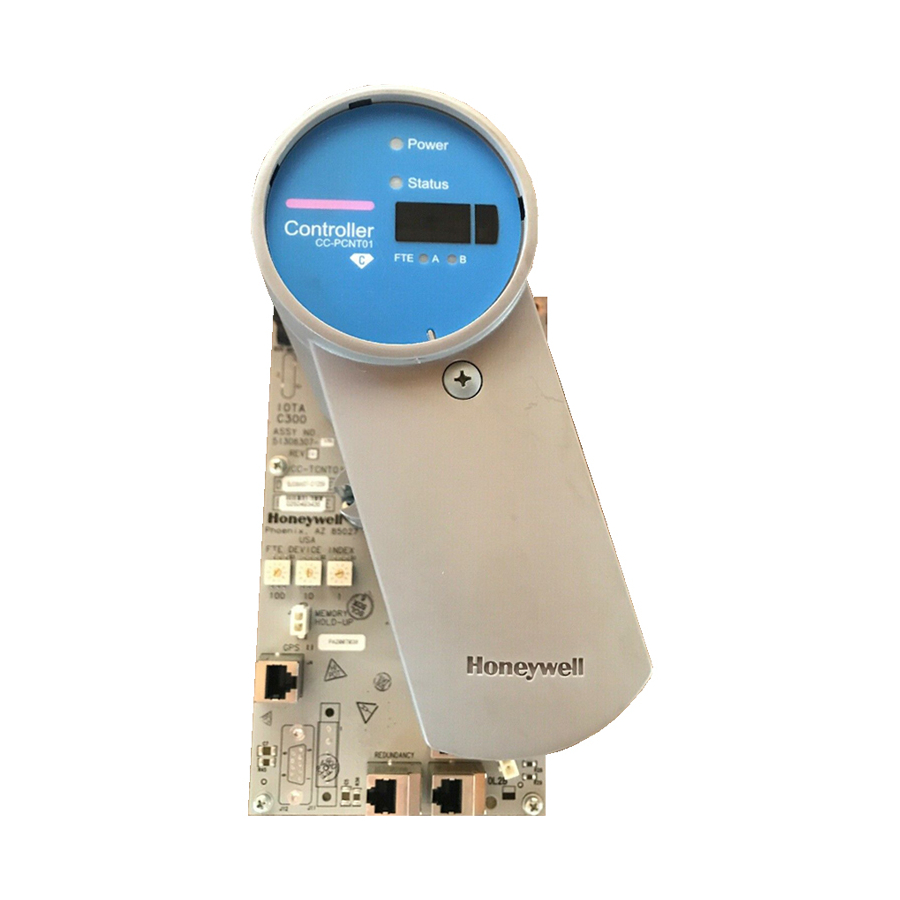
-
Contents
-
Table of Contents
-
Troubleshooting
-
Bookmarks
Quick Links
Honeywell Process Solutions
Series 8
C300 Controller
User’s Guide
EXDOC-XX11-en-500A
R500
April 2017
Release 500
Honeywell
Related Manuals for Honeywell C300
Summary of Contents for Honeywell C300
-
Page 1
Honeywell Process Solutions Series 8 C300 Controller User’s Guide EXDOC-XX11-en-500A R500 April 2017 Release 500 Honeywell… -
Page 2
In no event is Honeywell liable to anyone for any indirect, special or consequential damages. The information and specifications in this document are subject to change without notice. -
Page 3
About This Document Provides information that assists you in planning and designing activities, as well as the installation, operation, and troubleshooting of C300 Process Controllers in Experion LX system. Intended audience This document is intended for the following users: … -
Page 4
HART, AI-HL, AI-LLMUX, AO, AO-HART, DI-24, DI-SOE, DO-24B. Fault Tolerant Ethernet Overview and Provides basic installation instructions Implementation Guide and configuration requirements for a Fault Tolerant Ethernet (FTE) network and its components. Series 8 C300 Controller User’s Guide R500 Honeywell April 2017… -
Page 5
Honeywell Global TAC – China Contact: +86- 21-2219-6888 Phone: 800-820-0237 400-820-0386 Mail: Honeywell (China) Co., Ltd 33/F, Tower A, City Center, 100 Zunyi Rd. Shanghai 200051, People’s Republic of China Email: Global-TAC-China@honeywell.com R500 Series 8 C300 Controller User’s Guide April 2017 Honeywell… -
Page 6
WARNING symbol on the equipment refers the user to the product manual for additional information. The symbol appears next to required information in the manual. Series 8 C300 Controller User’s Guide R500 Honeywell April 2017… -
Page 7
Chassis Ground: Identifies a connection to the chassis or frame of the equipment shall be bonded to Protective Earth at the source of supply in accordance with national and local electrical code requirements. R500 Series 8 C300 Controller User’s Guide April 2017 Honeywell… -
Page 9: Table Of Contents
C300 Secondary Controller Installation ………………37 Series 8 I/O modules installation …………41 Series 8 FIM Installation …………….41 Upgrading C300 Controller Firmware …………. 41 C300 Controller behavior during firmware upgrade and timeout ……….41 R500 Series 8 C300 Controller User’s Guide April 2017…
-
Page 10
Create C300 Controller and CEE function blocks ……. 46 Configure CEEC300 block …………….53 Configure a Secondary C300 Controller block ……..58 Convert a non-redundant C300 Controller to a redundant controller ..60 Convert a redundant C300 Controller to a non-redundant controller ..63 Configure IOLINK function blocks …………64 Import/export C300 Controller configuration …….. -
Page 11
Server Displays tab ………………….157 Control Confirmation tab ………………….157 Identification tab ……………………157 LOAD C300 CONTROLLER CONFIGURATION ….159 About load operations ……………. 159 Loaded versus project database versions …………….159 Load initiation and load dialog box ………………160 Load action with compare parameters function ………….. -
Page 12
Upload to the Monitoring database ………… 172 7. C300 CONTROLLER OPERATION ……….. 173 C300 Controller start up …………..174 C300 Controller states in boot mode ……………….176 C300 Controller states in application mode ……………..177 C300 faceplate indicators/displays …………179 Power and Status LEDs ………………….180 Faceplate display information ………………..181… -
Page 13
7.12 Viewing controller operation and status in Control Builder ….199 7.13 C300 operating behaviors …………..201 Time management in the C300 Controller …………….201 Hardware Watchdog Timer ………………… 202 Critical Task Monitor …………………… 202 7.14 C300 Controller processing overload behavior ……203 Causes of controller overloading ………………… -
Page 14
Redundancy Link Status — RDNLINKFAILED …………….223 Controller redundancy specifications ……….223 9. C300 CONTROLLER MAINTENANCE ……..225 Periodic Checks ………………225 Recommended Spare Parts …………..225 C300 Controller module and IOTA replacement ……. 226 10. C300 CONTROLLER TROUBLESHOOTING ……231 10.1 Overview………………..231 10.2 What to do when faults occur ………… -
Page 15
Non-redundant C300 Controller with no Memory Retention ……….257 Non-redundant C300 Controller with Memory Retention…………258 Redundant Primary C300 Controller with no Memory Retention ……….. 261 Redundant Primary C300 Controller with Memory Retention ……….262 Secondary C300 Controller with no Memory Retention …………264 Secondary C300 Controller with Memory Retention ………….. -
Page 16
Table 2 C300 Controller IOTA Board Connector Summary ……….33 Table 3 Initial Load Order Guidelines …………….162 Table 4 C300 Controller Startup and Power On Self Test routine ……. 174 Table 5 Controller in Boot mode ………………. 177 Table 6 C300 Controller in Application mode ………….. 177 Table 7 C300 Controller LED indications ………….. -
Page 17
Contents Figures Figure 1 Series C form factor example …………….25 Figure 2 Redundant C300 Controller block in the Project tree ……..27 Figure 3 C300 Controller IOTA Board Features …………33 Figure 4 Sample Load Dialog ………………161 Figure 5 C300 Controller Startup and Boot Mode indications ……..176 Figure 6 C300 Controller faceplate features …………… -
Page 19: C300 Controller Purpose
1. C300 Controller Purpose This chapter provides the tasks that are related to using the C300 Controller with the Experion LX system. The following table provides the sections covered in this chapter. Click the topic to view Topic Getting started task list…
-
Page 20: Getting Started
Getting started The following table lists some of the tasks covered in this document that are related to implementing a C300 Controller in your Experion LX R500 system. What task do you want to perform? If You Want to . . .
-
Page 21
1. C300 Controller Purpose 1.1. Getting started If You Want to . . . Then, see this Topic . . . Review C300 Controller start up routines C300 Controller start up Review C300 Controller operating indications C300 Faceplate indicators/displays Shutdown a C300 Controller… -
Page 22
1. C300 Controller Purpose 1.1. Getting started Series 8 C300 Controller User’s Guide R500 Honeywell April 2017… -
Page 23: C300 Controller Planning And Design
2. C300 Controller Planning and Design This chapter provides information about system planning and design of the C300 Controller. The following table provides the sections covered in this chapter. Click the topic to view it. Topic Review Experion LX system capabilities…
-
Page 24: Control Hardware Planning Guide
DI-SOE that supports sequence of events. Series 8 form factor All Series 8 control hardware is constructed using the same form factor; that is, the C300 Controller modules, and Series 8 I/O modules, and Series 8 FIMs all mount on their associated Input Output Termination Assemblies (IOTAs), which are installed on channel hardware specifically designed to support Series 8 hardware installation.
-
Page 25
2. C300 Controller Planning and Design 2.4. C300 Controller Figure 1 Series 8 form factor example R500 Series 8 C300 Controller User’s Guide April 2017 Honeywell… -
Page 26: C300 Controller
500 milliseconds. C300 Controller block When a C300 Controller block is added to the Project tree in Control Builder, a graphic representation of a controller module and its resident function blocks appears as shown in Figure 2.
-
Page 27: C300 Controller Execution Environments
The C300 Controller supports three Execution Environment (EE) function blocks. One is the Control EE block, (CEEC300). The other two are I/O Link blocks, (IOLINK). The IOLINK blocks in the C300 support connection and communication with all Series 8 I/O modules.
-
Page 28: I/O Modules Supported By The C300 Controller
The C300 Controller supports Series 8 I/O modules. Series 8 I/O modules are connected to the C300 by a pair of I/O Link Interfaces. Two IO Link interfaces, which are redundant, provide connection between the C300 controller and associated I/O modules.
-
Page 29: Control Network Considerations
Control network considerations In Experion LX system, the C300 Controller exists as a single node on a FTE network. FTE is the only supported communication protocol for C300 Controllers with Experion LX. C300 Peer communication with Experion LX nodes The C300 supports peer communications with the C300 Controller nodes in Experion LX Release 500.
-
Page 31: C300 Controller Installation And Upgrades
3. C300 Controller Installation and Upgrades This chapter describes the information about installing various Series 8 components. Physical descriptions of the components as well as procedures for installing these components are provided. The following table provides the sections covered in this chapter. Click the topic to view…
-
Page 32: Series 8 Control Hardware Installation Requirements
C300 Controller installation C300 Controller assembly The C300 Controller consists of an Input/Output Terminal Assembly (IOTA) board and the controller module which is housed within a plastic cover and is mounted on the IOTA board. The Controller assembly is installed in a control cabinet on vertically-mounted channels specifically for Series 8 control hardware.
-
Page 33
3. C300 Controller Installation and Upgrades 3.2. C300 Controller installation R500 Series 8 C300 Controller User’s Guide April 2017 Honeywell… -
Page 35: Table 2 C300 Controller Iota Board Connector Summary
3. C300 Controller Installation and Upgrades 3.2. C300 Controller installation Figure 3 C300 Controller IOTA Board Features Table 2 C300 Controller IOTA Board Connector Summary C300 IOTA Board Description Fuse IOL1A, IOL1B (Gray cable) Redundant IOLINK connectors for IOLINK 1 and…
-
Page 36
A Series 8 power supply and optional battery backup hardware installed in the cabinet. Following are the parts included: C300 Controller assembly (control module with IOTA board and mounting hardware) 2 STP Cat5 Ethernet cables (one Yellow cable, one Green cable) … -
Page 37
The secondary controller may be installed on a separate channel from the primary controller. To install a C300 Controller, perform the following steps. Step Action Refer to appropriate site location drawings for the specified controller installation location, controller Device Index (FTE address) and wiring diagrams. -
Page 38
Connect a second IOLINK cable pair to IOL2A and IOL2B for IOLINK 2 interface of the controller. Note that when connecting Redundant C300 Controller pairs; connect the primary controller IOLINK and the redundant partner IOLINK to the same IOLink cable pair. -
Page 39: C300 Secondary Controller Installation
‘Module is Redundant’ check box. C300 Secondary Controller Installation Creating a C300 Controller redundant pair is as simple as installing a second controller in the control hardware cabinet. Refer to the C300 Controller assembly to review the location of the cable connections.
-
Page 40
To install a partner secondary C300 Controller, perform the following steps. Step Action If the primary C300 FB already exists in Control Builder and it is currently configured as a redundant controller, select the Redundancy tab and click the Disable Synchronization button to set the Auto-Synchronization State parameter to «DISABLED.»… -
Page 41
3. C300 Controller Installation and Upgrades 3.2. C300 Controller installation Step Action Be sure component side of IOTA is facing up. Refer to the figure below. Assemble mounting screws, washers and spacers provided. Insert spacers and washers between backside of IOTA and front of channel. -
Page 42
Connect a second IOLINK cable pair to IOL2A and IOL2B for IOLINK 2 interface of the controller. Note that when connecting Redundant C300 Controller pairs, connect the primary controller IOLINK and the redundant partner IOLINK to the same IOLink cable pair. -
Page 43: Series 8 I/O Modules Installation
I/O Modules Firmware Upgrade Guide about using CTool to upgrade firmware in Series 8 components C300 Controller behavior during firmware upgrade and timeout The following indications are shown on the faceplate display of the C300 Controller during the firmware upgrade operation. …
-
Page 44
3. C300 Controller Installation and Upgrades 3.5. Upgrading C300 Controller Firmware The controller is set to timeout in 4.5 minutes if the firmware upgrade operation is not completed. When the timeout occurs, the controller aborts the upgrade operation and returns to the operating state (ALIV or RDY) prior to the start of the firmware upgrade. -
Page 46
3. C300 Controller Installation and Upgrades 3.5. Upgrading C300 Controller Firmware Series 8 C300 Controller User’s Guide R500 Honeywell April 2017… -
Page 47: C300 Controller Configuration
Create C300 Controller and CEE function blocks Configure CEEC300 block Configure a Secondary C300 Controller block Convert a non-redundant C300 Controller to a redundant controller Convert a redundant C300 Controller to a non-redundant controller Configure IOLINK function blocks Import/export C300 Controller configuration…
-
Page 48: Configuration Overview
If you are using Simplified Enterprise Model Builder (SEMB) application to create an asset model of your system, assets that represent C300 Controllers can be created and added to your model following the same procedures for creating assets and alarm groups.
-
Page 49: Specifying A Time Server
4.2. Create C300 Controller and CEE function blocks Specifying a Time Server The C300 Controller requires a reference source for time in order to power up and normally operate, but limited controller operation can be achieved in cases where system time is not available.
-
Page 50: Create C300 Controller And Cee Function Blocks
Control Execution Environment (CEE). Once created, the function blocks appear in the Project tab view of Control Builder. The CEEC300 block supports execution of a set of function blocks for solving control applications which run in the C300 as a software layer built on top of the control software infrastructure.
-
Page 51
4. C300 Controller Configuration 4.2. Create C300 Controller and CEE function blocks Considerations All illustrations used in the procedure are for example purposes only. To configure a C300 Controller block, perform the following steps. Step Action Result Click File > New > Controllers > C300 The C300 Block configuration form with a Controller (2 I/O Links). -
Page 52
4. C300 Controller Configuration 4.2. Create C300 Controller and CEE function blocks Step Action Result Enter the desired name of up to 16 Moves cursor to the Item Name field. characters or accept the default. Press <Tab>. Note: Tag Name is limited to 16… -
Page 53
4. C300 Controller Configuration 4.2. Create C300 Controller and CEE function blocks Step Action Result In the Temperature High Alarm (degC) Moves cursor to the CPU Free Low field, accept the default or enter a value Alarm (%) field. at which an alarm is generated for controller hardware high temperature. -
Page 54
4. C300 Controller Configuration 4.2. Create C300 Controller and CEE function blocks Step Action Result If you have a Distributed Server Architecture (DSA), you must enter the Control Area assignment for this Server. (Note that area code assignments are made through the Station application.) If you do not have a DSA, you can skip this field if area is not… -
Page 55
4. C300 Controller Configuration 4.2. Create C300 Controller and CEE function blocks Step Action Result Use the on-line help as a guide to The Server Displays configuration form complete the configuration entries on this appears. tab. Click the Server Displays tab. -
Page 56
4. C300 Controller Configuration 4.2. Create C300 Controller and CEE function blocks Step Action Result The following block icons now appear in the Project window: C300 Controller block, and its associated CEEC300 block 2 IOLINK blocks and … -
Page 57: Configure Ceec300 Block
4. C300 Controller Configuration 4.3. Configure CEEC300 block Configure CEEC300 block A CEE block is created automatically when a C300 Controller function block is added to the Project tab. Prerequisites Control Builder is running Tree windows are open Considerations All illustrations used in the procedure are for example purposes only.
-
Page 58
Enter the desired name of up to 16 Moves cursor to Item Name field. characters or accept the default. Press <Tab>. Enter Item Name. Press <Tab>. Moves cursor to Base Execution Period field. Series 8 C300 Controller User’s Guide R500 Honeywell April 2017… -
Page 59
Otherwise, an error message appears as follows: «CEE BASEPERIOD cannot be changed because IOLINK TYPE of at least one IOLINK of this C300 has been configured.” Accept the default or select desired Moves cursor to User Lock for CEE Idle field. -
Page 60
Click Server History tab and proceed to Step 25. Enter the valid name for the existing Moves cursor to Peer Subscription Period peer environment. column. Press <Tab>. Series 8 C300 Controller User’s Guide R500 Honeywell April 2017… -
Page 61
Click OK. REFERENCE — INTERNAL Refer to the Experion LX Control Builder Components Reference, Component Categories and Types and the Experion LX Planning Guide. R500 Series 8 C300 Controller User’s Guide April 2017 Honeywell… -
Page 62: Configure A Secondary C300 Controller Block
4. C300 Controller Configuration 4.4. Configure a Secondary C300 Controller block Configure a Secondary C300 Controller block When a C300 Controller is configured as Redundant, the Secondary C300 Controller block is added to the Project tab automatically. Prerequisites Control Builder is running …
-
Page 63
4. C300 Controller Configuration 4.4. Configure a Secondary C300 Controller block Step Action Result Enter the desired name of up to 16 Moves cursor to the Item Name field. characters or accept the default. Press <Tab>. Enter Item Name. Press <Tab>. -
Page 64: Convert A Non-Redundant C300 Controller To A Redundant Controller
Tree windows are open Ensure that a C300 Controller is properly installed in the same control cabinet as the C300 Controller designated to become the redundant partner. The C300 Controller hardware and firmware must be identical for both controllers in a redundant pair.
-
Page 65
4. C300 Controller Configuration 4.5. Convert a non-redundant C300 Controller to a redundant controller Step Action Result icon. Click Module Properties… The C300 Block configuration form. Select the Module is redundant A default tag name of the secondary check box. -
Page 66
4. C300 Controller Configuration 4.6. Convert a redundant C300 Controller to a non-redundant controller Step Action Result Click OK. The C300 Controller configuration form closes. In the Project window: The C300 Controller icon indicates that it is configured as redundant, (showing a double controller icon). -
Page 67: Convert A Redundant C300 Controller To A Non-Redundant Controller
Control Builder is running Tree windows are open Make sure that the current primary C300 Controller is physically configured with the odd Device Index. If not, enable synchronization, wait for initial-sync to complete, and manually command switchover. Considerations This procedure can be performed on-process.
-
Page 68: Configure Iolink Function Blocks
Configure IOLINK function blocks Two IOLINK blocks are created automatically when a C300 Controller function block is added to the Project tab. These blocks provide the interface to the controller for associated I/O Module blocks.
-
Page 69
4.7. Configure IOLINK function blocks Step Action Result In the Project window, right-click on the The shortcut menu appears. IOLINK_1BLK block icon. Click Module Properties… The IOLINK Block configuration form appears. R500 Series 8 C300 Controller User’s Guide April 2017 Honeywell… -
Page 70
Accept the default or click the drop-down The IOLINK block configuration form list and select the I/O type. closes since no other data on this form is available in the Project mode. Click OK. Series 8 C300 Controller User’s Guide R500 Honeywell April 2017… -
Page 71: Import/Export C300 Controller Configuration
When using the export function the Device Index information for the C300 is exported, but not the controller’s IP Address. This enables import of the C300’s configuration into a different server cluster, and allows the C300 to use a different IP Address based upon that server cluster’s base IP Address.
-
Page 72
IP Address based on this new Device Index. In the Control Builder, configure as a new controller. Refer to the C300 Controller Configuration to configure a new controller. Series 8 C300 Controller User’s Guide R500 Honeywell April 2017… -
Page 73: 4.10 Create A Control Module
The following graphic shows Control Builder with a Control Module chart shown in the control drawing area. Prerequisites Control Builder is running Tree windows are open R500 Series 8 C300 Controller User’s Guide April 2017 Honeywell…
-
Page 74
The new Control Module is automatically saved to your hard drive. Select Edit > Module Properties… or double-click inside the chart to open the Control Module parameter configuration form for input. Series 8 C300 Controller User’s Guide R500 Honeywell April 2017… -
Page 75
Enter a new Control Module name in the Name field along with a description in the Description field. Using the F1 key to access context-sensitive Help, fill in the remaining fields as required. R500 Series 8 C300 Controller User’s Guide April 2017 Honeywell… -
Page 76: Assign Control Modules And Ioms To A Ceec300 Block
Once a Control Module (CM) or Sequential Control Module (SCM) is created, you can assign it to a CEEC300 block of a C300 Controller. Use the following procedure as a general guide to assign configured CMs and I/O Modules (IOMs) to the CEEC300 block.
-
Page 77
(There is no set of Assignment. Or, click assignment default state for the dialog, so it may button in the toolbar. appear with different active fields than shown below.) R500 Series 8 C300 Controller User’s Guide April 2017 Honeywell… -
Page 78
Available Modules and Assigned Modules lists. With CMs/SCMs tab selected, click listed Highlights selection and configured CM to be assigned to a CEE. CEEs appear in the Assign To list. Series 8 C300 Controller User’s Guide R500 Honeywell April 2017… -
Page 79
Be sure correct CEE is selected in list. desired CEE in list. Selected CM is assigned to the selected Click the CEE and appears in the Assigned assign button. Modules list. R500 Series 8 C300 Controller User’s Guide April 2017 Honeywell… -
Page 80
4. C300 Controller Configuration 4.11. Assign Control Modules and IOMs to a CEEC300 block Step Action Result Click IOMs tab in Available Modules Configured IOMs appear in list. section. Series 8 C300 Controller User’s Guide R500 Honeywell April 2017… -
Page 81
CEE and appears in the Assigned assign button. Modules list. Repeat Steps 2 to 4 to assign other Complete CM, SCM, and IOM CMs/SCMs. Or, repeat Steps 5 to 8 to assignments. assign other IOMs. R500 Series 8 C300 Controller User’s Guide April 2017 Honeywell… -
Page 82: 4.12 Copy Control Modules
Project Tree. copied. Click Edit > Copy. Selected Control Module block is saved to Control Builder clipboard Alternate method: and Name New Function Block(s)… dialog appears. Click <Ctrl>-C. Series 8 C300 Controller User’s Guide R500 Honeywell April 2017…
-
Page 83
4. C300 Controller Configuration 4.13. Assign I/O Modules to C300 IOLINK blocks Step Action Result Change the Control Module block’s The copied Control Module block is Tagname in the Destination column of assigned a new name. the Name New Function Block(s) dialog… -
Page 84: 4.13 Assign I/O Modules To C300 Iolink Blocks
IOLINK blocks. ATTENTION I/O assigned to the I/O Link of a C300 may only be associated with and directly controlled by the CEE executing on the same C300 Controller. In other words, I/O devices operating on a C300 Controller’s I/O Link may not be directly associated with control strategies running on the CEE of another controller.
-
Page 85
4. C300 Controller Configuration 4.13. Assign I/O Modules to C300 IOLINK blocks To assign Series 8 IO Modules to IOLINK blocks, perform the following steps. Step Action Result Click Edit > Execution Environment The Execution Environment Assignment dialog box appears. (There is no set Assignment. -
Page 86
4. C300 Controller Configuration 4.13. Assign I/O Modules to C300 IOLINK blocks With IOMs tab selected, click desired Highlights selection and configured IOM to be assigned to given IOLINK. IOLINKs appear in the Assign To list. Accept default IOLINK selection or click Be sure correct IOLINK is selected in list. -
Page 87
4. C300 Controller Configuration 4.13. Assign I/O Modules to C300 IOLINK blocks Repeat Steps 2 to 4 to assign other Complete IOM assignments. IOMs. R500 Series 8 C300 Controller User’s Guide April 2017 Honeywell… -
Page 88: 4.14 Add An I/O Channel To A Control Module
Control Builder is running Tree windows are open Considerations All illustrations used in the procedure are for example purposes only. Blocks appear as Block Symbols on the Control Module chart. Series 8 C300 Controller User’s Guide R500 Honeywell April 2017…
-
Page 89
Control Building Guide. If you are building a control strategy to include insertion points, refer to Creating a strategy to use insertion points in the Control Building User’s Guide. R500 Series 8 C300 Controller User’s Guide April 2017 Honeywell… -
Page 91: C300 Configuration Form Reference
Controller block. The Main tab contains most of the parameters that must be configured when setting up a C300 Controller. It also displays the important states of the C300 Controller and supports the key commands associated with C300 Controller operation.
-
Page 92
Embedded FTE Base Ethernet IP Address and the configured Device Index. State Information Controller State C300STATE Shows C300 Controller’s current module state. Redundancy Role RDNROLESTATE Shows C300 Controller’s current redundancy role. Series 8 C300 Controller User’s Guide R500 Honeywell April 2017… -
Page 93
Advanced Configuration ALMENBSTATE Alarming Enabled Allows user to set the alarm reporting function used when an alarm condition is detected by the function block. R500 Series 8 C300 Controller User’s Guide April 2017 Honeywell… -
Page 94
Host IP Address HOSTIPPRI Indicates the IP address for the node hosting the simulation program. Host Name HOSTNAMEPRI Specifies the network name for the node hosting the simulation program. Simulation Node Operation Series 8 C300 Controller User’s Guide R500 Honeywell April 2017… -
Page 95: Redundancy Tab
Redundancy tab The Redundancy Tab displays redundancy-related information and allows redundancy commands to be issued when the C300 FB is opened on the Monitor Tree in Control Builder. The following table summarizes the parameter data you can monitor and/or R500…
-
Page 96
5. C300 Configuration Form Reference 5.1. C300 Controller Block configure on the Redundancy tab of the configuration form for the selected C300 block. Refer to the Redundancy parameters for further descriptions of these parameters. Note that the Redundancy tab is exposed only when the Controller is configured as redundant. -
Page 97
RDNXFERMAX Max Redundancy Maximum amount of redundancy data traffic Traffic (bytes/sec) across the redundancy private path throughput since power up or last statistics reset. R500 Series 8 C300 Controller User’s Guide April 2017 Honeywell… -
Page 98
RDNOPMSTATUS OPM Status Status parameter indicating the notifications Note: This parameter generated by the primary is not supported in controller during an On- this release. Process Migration session. Series 8 C300 Controller User’s Guide R500 Honeywell April 2017… -
Page 99: System Time Tab
5.1. C300 Controller Block System Time tab The System Time tab contains information about the C300 Controller’s time source and synchronization with that time source. The «System Time» and «System Time Synchronization Status» subgroups on this tab provide current controller system time and indicates the time source with which it is synchronized and status of synchronization with that source.
-
Page 100: Statistics Tab
Statistics tab The Statistics Tab contains various statistical parameters used for maintaining and monitoring C300 Controller performance. Such information includes CPU utilization, hardware temperature and communications sub-system (CDA) statistics. The following table summarizes the parameter data you can monitor on the Statistics tab of the configuration form for the selected C300 block.
-
Page 101
Initiator Output Rate TINUMOUTMSGAVGP Max Initiator Output TINUMOUTMSGMAXP Rate Responder Input TRNUMINMSGAVGPS Rate TRNUMINMSGMAXPS Max Responder Input Rate Responder Output TRNUMOUTMSGAVGP Rate Max Responder TRNUMOUTMSGMAXP Output Rate PCDI Network Message Statistics R500 Series 8 C300 Controller User’s Guide April 2017 Honeywell… -
Page 102: Peer Connections Tab
Peer Connections tab The Peer Connections tab contains data indicating the number of peer connections for both initiator and responder types between the C300 Controller and other peer-capable nodes, such as, C300 Controllers. The following table summarizes the parameter data you can monitor on the Peer Connections tab of the configuration form for the selected C300 block.
-
Page 103
5.1. C300 Controller Block Peer Responding Connections Responding to C300s TNUMC3OUTCON Shows the number of originator C300 Controllers. Responding to FIM4s TNUMSCFIMOUTCON Shows the number of originator Series 8 FIMs. R500 Series 8 C300 Controller User’s Guide April 2017 Honeywell… -
Page 104: Hardware Information Tab
The parameters provided here are used for maintenance, troubleshooting and problem description purposes. The following table summarizes the parameter data you can view on the Hardware Information tab of the configuration form for the selected C300 block. Plain Text…
-
Page 105: Fte Tab
Two separate MARTs are maintained — one for FTE nodes and one for non-FTE nodes. The following table summarizes the parameter data you can monitor on the FTE tab of the configuration form for the selected C300 block. Plain Text Parameter Name…
-
Page 106
LANARXRATE Indicates communication receive rate in kilobits per (kBit/sec) second (kbps) for port A Note: This parameter (Yellow Tree Port) on the is not supported in FTE Bridge. this release. Series 8 C300 Controller User’s Guide R500 Honeywell April 2017… -
Page 108
(kbps) for port B (Green is not supported in Tree Port) on the FTE this release. Bridge. FTE Statistics Number of FTE NUMFTENODES Current number of FTE Nodes nodes within FTE community. Series 8 C300 Controller User’s Guide R500 Honeywell April 2017… -
Page 109
Port B. InterLAN Comm INTERLANFAILED Status indicator for Inter- Failed LAN communications — indicates that inter-LAN communications have failed. R500 Series 8 C300 Controller User’s Guide April 2017 Honeywell… -
Page 110: Utp/Tcp Tab
UTP/TCP tab The UDP/TCP tab displays statistics related to open UDP and TCP connections associated with this C300 Controller. These parameters provided here are used for maintenance and performance monitoring purposes. The following table summarizes the parameter data you can monitor on the UDP/TCP tab of the configuration form for the selected C300 block.
-
Page 111
LISTEN state from SYN-RCVD state. Connection Resets TCPESTABRESETS Number of times TCP connections have made a direct transition to CLOSED state from either ESTABLISHED state or CLOSE-WAIT state. R500 Series 8 C300 Controller User’s Guide April 2017 Honeywell… -
Page 112: Ip/Icmp Tab
The IP/ICMP tab displays statistics related to IP and ICMP protocol messages associated with (that is, originating in or received by) this C300 Controller. These types of messages are generally associated with maintenance and status operations on the network. The following table summarizes the parameter data you can monitor on the IP/ICMP tab of the configuration form for the selected C300 block.
-
Page 113
Number of input IP Discarded for Resrcs datagrams for which no problems were encountered to prevent their continued processing, but which were discarded; for example, for lack of buffer space. R500 Series 8 C300 Controller User’s Guide April 2017 Honeywell… -
Page 114
IPREASSEMOKS Number of IP datagrams Reassembled successfully reassembled. Fragments IPREASSMFAILS Number of failures Reassembly Fails detected by the IP reassembly algorithm, for whatever reason: timed out, errors, and so on. Series 8 C300 Controller User’s Guide R500 Honeywell April 2017… -
Page 115
ICMP-specific errors such as bad ICMP checksums and bad length. Dest. Unreachable ICMPINDESTUNREAC Number of ICMP Msgs Recvd Destination Unreachable messages received. R500 Series 8 C300 Controller User’s Guide April 2017 Honeywell… -
Page 116: Soft Failures Tab
Number of ICMP Echo Messages Sent Reply messages sent. Soft Failures tab The Soft Failures tab provides indications of various soft failure conditions for the C300 Controller hardware. Refer to the C300 Controller soft failures table in the Troubleshooting section for more detailed information and corrective actions in clearing these faults.
-
Page 117
Warning Watchdog Timer is being refreshed late and close to the timeout limit. Critical Task TASKHLTHMON A key task within the Watchdog Warning controller is executing less frequently than normal. R500 Series 8 C300 Controller User’s Guide April 2017 Honeywell… -
Page 118: Server History Tab
The Server History tab is common to all configuration forms for tagged blocks in Control Builder. The following table summarizes the parameter data you can monitor and configure on this tab of the configuration form for the selected C300 block. ATTENTION…
-
Page 119
Select the Exception type of (Station history collection. only) Gating Parameter HIST.GATEPARAM Optional gating parameter to define conditions under which data for this parameter should be collected. Gate State HIST.GATEVALUE Defines gate state for R500 Series 8 C300 Controller User’s Guide April 2017 Honeywell… -
Page 120: Server Displays Tab
The Server Displays tab is common to all configuration forms for tagged blocks in Control Builder. The following table summarizes the parameter data you can monitor and configure on this tab of the configuration form for the selected C300 block. ATTENTION…
-
Page 121
Number of Groups GROUP.NUMPARAMS Defines the number of group parameters to be included in Groups Configuration table. Group # GROUP.NUMBER Defines Group number to be associated with this group parameter. R500 Series 8 C300 Controller User’s Guide April 2017 Honeywell… -
Page 122: Control Confirmation Tab
The Identification tab is common to all configuration forms for tagged blocks in Control Builder. The following table summarizes the parameter data you can monitor and configure on this tab of the configuration form for the selected C300 block. Plain Text…
-
Page 123
Otherwise, it may just show default login. If this block is in Version Control System, modifications apply to last version of block. R500 Series 8 C300 Controller User’s Guide April 2017 Honeywell… -
Page 124: Secondary C300 Block
(MODISREDUN) check box is selected on the Primary C300 configuration form Main tab. The Secondary C300 configuration form contains the same tabs and parameters as the primary with the exception of a few parameters on the Main and Redundancy tabs.
-
Page 125: Ceec300 Function Block
5.3. CEEC300 Function Block CEEC300 Function Block The CEEC300 function block is created when a new C300 Controller block is created and configured in the Project tree in Control Builder. The following sections identify and describe all user-visible parameters associated on the CEEC300 configuration form. For more details about these parameters refer the Control Builder Parameter Reference.
-
Page 126
Enable Memory Limit Allows user to enable Exceeded Alarm the alarm reporting function for Memory Limit Exceeded alarm. Powerup/Restart Settings RRRCEESTATE CEE State Shows the CEE state after a RAM retention restart. Series 8 C300 Controller User’s Guide R500 Honeywell April 2017… -
Page 127
Inhibit Notifications — NOTIFINHIBIT Indicates if the display of CEE and Contents notifications associated with the CEESIMC300 and its contents is inhibited on the Station’s Alarm Summary. R500 Series 8 C300 Controller User’s Guide April 2017 Honeywell… -
Page 128: Peer Configuration Tab
Store Expiration Time PEERSTRRESP [ ] Shows the expiration time used in waiting for Store responses for specific CEE peers (such as C300s) and non-CEE data servers (such as OPC Servers). Series 8 C300 Controller User’s Guide R500 Honeywell April 2017…
-
Page 129: Statistics Tab
Maximum NUMNTFRQUMAX The number of Notifications Rate Notification Requests per second maximum. Whole Array Transfer Statistics CPEERWAAVGPPS Whole Array (WA) Indicates the average Peer Responder peer responder rate. Rate R500 Series 8 C300 Controller User’s Guide April 2017 Honeywell…
-
Page 130
Exchange Statistics Exchange Request NUMEXCRQUAVG The average exchange Rate request throughput. Maximum Exchange NUMEXCRQUMAX The maximum Request Rate exchange request throughput. Exchange Response NUMEXCRSPAVG The average exchange Rate response throughput Series 8 C300 Controller User’s Guide R500 Honeywell April 2017… -
Page 131
CEE per second. Maximum OPC EXTGETRQUMAX The maximum number Pull/Get Rate of completed Get requests to all external servers, such as an OPC server, from this CEE per second. R500 Series 8 C300 Controller User’s Guide April 2017 Honeywell… -
Page 132
Maximum Transmit NUMMBTCPXMITMSG The maximum number Messages/sec of Modbus TCP transmit messages on average per second. Transmit Bytes/sec NUMMBTCPXMITBYTE The number of Modbus TCP transmit bytes on average per second. Series 8 C300 Controller User’s Guide R500 Honeywell April 2017… -
Page 133
Maximum Receive NUMMBTCPRCVBYTE The maximum number Bytes/sec of Modbus TCP receive bytes per second. Invalid Receive MBTCPINVALIDRCVM The Modbus TCP SGCOUNT Message Count invalid receive message count. R500 Series 8 C300 Controller User’s Guide April 2017 Honeywell… -
Page 134: Cpu Loading Tab
For example: CPUCYCLEAVG[0] is for Phase 1; CPUCYCLEAVG[1] is for Phase 2; and so on. CPUCYCLEAVG [40] contains the average value across all 40 phases. Series 8 C300 Controller User’s Guide R500 Honeywell April 2017…
-
Page 135: Cpu Overruns Tab
CEEC300 block. Plain Text Parameter Name User Notes Configurable CPU Overruns Table (%) Current Hour Cycle CRCYCLEOVRN A count of cycle [0…40] Overruns overruns that have occurred during the current hour. R500 Series 8 C300 Controller User’s Guide April 2017 Honeywell…
-
Page 136: Memory Tab
Memory tab The Memory tab contains data on general memory usage in the C300. It also shows memory usage parameters in terms of internal memory units: descriptors and blocks. The following table summarizes the parameter data you can monitor on the Memory tab of the configuration form for the selected CEEC300 block.
-
Page 137
Free Memory Blocks Number of free (available) memory blocks. External Memory NUMEXTBLKS Number of external Blocks memory blocks. Stack Usage MAXSTACK Maximum CEEB Maximum CEE Stack % budgeted stack in percent. R500 Series 8 C300 Controller User’s Guide April 2017 Honeywell… -
Page 138: Peer Communications Tab
IOLINK peer originator block. CPEERAVGPPSCONN Average Get Rate The average number of peer parameters/sec processed by the CEE. CPEERMAXPPSCONN Maximum Get Rate The maximum number of peer parameters/sec processed by the CEE. Series 8 C300 Controller User’s Guide R500 Honeywell April 2017…
-
Page 139: Exchange Communications Tab
Note: This tab is not supported in this release. The Exchange Communications tab contains information about exchange connections between the C300 controller and a target controller or programmable logic controller. It gives statistics for connections initiated by the CEEC300 block. The following table summarizes the parameter data you can monitor on the Exchange Communications tab of the configuration form for the selected CEEC300 block.
-
Page 140: Display Communications Tab
Display Communications tab The Display Communications tab contains information about display connections to the C300 (that is, Control Builder, Station, and so on). The following table summarizes the parameter data you can monitor on the Display Communications tab of the configuration form for the selected CEEC300 block.
-
Page 141: Block Types Info Tab
CCL Library BLKTYPLIB Shows the name of the CCL containing the block type. Block Size (bytes) BLKTYPSIZE Shows the size of the block type footprint. R500 Series 8 C300 Controller User’s Guide April 2017 Honeywell…
-
Page 142: Cab Types Info Tab
CAB load. If you want to disable CAB in a C300 where it was previously enabled, you must first delete all CAB instances and types from the controller. Series 8 C300 Controller User’s Guide R500 Honeywell April 2017…
-
Page 143: Custom Types Info Tab
Custom Types Info tab of the configuration form for the selected CEEC300 block. Plain Text Parameter Name User Notes Configurable Custom Types Represented Custom Data Blocks(CDB) and Phase Blocks Instantiated Block NUMCDDMTYPES The number of custom data definition manager Types types. R500 Series 8 C300 Controller User’s Guide April 2017 Honeywell…
-
Page 144: Server History Tab
Builder. Refer to the Identification tab for a table that summarizes the parameter data you can monitor and configure on this tab of the configuration form for the selected CEEC300 block. Series 8 C300 Controller User’s Guide R500 Honeywell April 2017…
-
Page 145: Iolink Block
5.4. IOLINK Block IOLINK Block The IOLINK function block is created when a new C300 Controller block is added to the Project tree in Control Builder. The following sections identify and describe all user- visible parameters associated on the IOLINK configuration form. For more details about these parameters refer to the Control Builder Parameter Reference.
-
Page 146
Shows the I/O link has Exceeded exceeded the maximum error limit. Not Active Supervisor NOTACTSUPV Indicates that the IOL interface daughter card could not transition into the active supervisor role. Series 8 C300 Controller User’s Guide R500 Honeywell April 2017… -
Page 147: Memory Stats Tab
Memory Stats tab of the configuration form for the selected IOLINK block. Plain Text Parameter Name User Notes Configurable Memory Stats R500 Series 8 C300 Controller User’s Guide April 2017 Honeywell…
-
Page 148
Memory Buffers In BUFXUSED The current number of memory buffers used in the Monitoring mode. Maximum Memory BUFXMAX The maximum number Buffers Used of memory buffers used. Series 8 C300 Controller User’s Guide R500 Honeywell April 2017… -
Page 149: Statistics Tab
Channel A+ Edges PRIIFCHNPLA The number of I/O link channel A missed and the edge transitions encountered locally by the primary link interface. R500 Series 8 C300 Controller User’s Guide April 2017 Honeywell…
-
Page 150
Last IOL Command LASTIOLCMD The last I/O link command requested through the COMMAND parameter or the last SELECT_CH_A / SELECT_CH_B command automatically issued when periodic channel swap is enabled. Series 8 C300 Controller User’s Guide R500 Honeywell April 2017… -
Page 151
The number of I/O Link channel B errors encountered by the Secondary Link Interface. Channel B Silences SECIFCHNSILB The number of I/O Link channel B silences encountered by the Secondary Link Interface. R500 Series 8 C300 Controller User’s Guide April 2017 Honeywell… -
Page 152
Channel A+ Total TOTCHNPLA The total I/O Link Edges missed and the edge transitions on channel Channel B Total TOTCHNERRB The total I/O Link errors Errors on channel B. Series 8 C300 Controller User’s Guide R500 Honeywell April 2017… -
Page 153
The number of I/O link overruns that have Hour occurred in the current hour. Overruns — Previous OVERRUNSPREV Shows the number of Hour I/O link overruns that have occurred in the previous hour. R500 Series 8 C300 Controller User’s Guide April 2017 Honeywell… -
Page 154
Local Data Transfer LCDXFIFORATEA Indicates the average number of parameters accessed through Local Data Transfer FIFO per second. DIFIFORATEA DI Priority DO Priority DOFIFORATEA Maximum I/O Link Requests Per Second Series 8 C300 Controller User’s Guide R500 Honeywell April 2017… -
Page 155
OVRRUNCURHR Overruns Current Process Data Cycle Overruns that have Hour occurred during the Current Hour. Overruns Previous OVRRUNPREVHR Process Data Cycle Hour Overruns that have occurred in the Previous Hour. R500 Series 8 C300 Controller User’s Guide April 2017 Honeywell… -
Page 156: I/O Link Status Tab
PRIRCVCHN Indicates the channel that is actively listening to the transmitted messages. Channel A Errors PRICHNERRA Shows the number of I/O link channel A errors encountered by the Primary IOP. Series 8 C300 Controller User’s Guide R500 Honeywell April 2017…
-
Page 157
The number of I/O link channel B missed plus edge transitions encountered by the primary IOM. PRICOMMERR Last Error Shows the last I/O Link communication error experienced by the Primary IOP. Secondary IOPs R500 Series 8 C300 Controller User’s Guide April 2017 Honeywell… -
Page 158
Indicates the number of I/O link channel B errors encountered by the Secondary IOP. Channel B Silences SECCHNSILB Shows the number of I/O link channel B silences encountered by the Secondary IOP. Series 8 C300 Controller User’s Guide R500 Honeywell April 2017… -
Page 159: I/O Status Summary Tab
IOP Block Name corresponding Primary IOP/IOM Tag. Configured IOP Type IOMTYPE Indicates the configured IOP type. IOP Status IOMSTSA and Shows the status of the IOMSTSB specific physical I/O Module. R500 Series 8 C300 Controller User’s Guide April 2017 Honeywell…
-
Page 160
Overruns — Previous IOPORPREV Indicates the number of Hour I/O Link overruns that have occurred in the previous hour. Cached Parameters NUMCACHE The number of cached parameters residing in the IOLINK. Series 8 C300 Controller User’s Guide R500 Honeywell April 2017… -
Page 161: Iota Summary Tabs
Active Receive Indicates the actual Channel active receive channel for the Series 8 IOM. Channel A Errors PHYCHNERRASC1 Shows the I/O Link errors on Channel A for the Series 8 IOM. R500 Series 8 C300 Controller User’s Guide April 2017 Honeywell…
-
Page 162: Server History Tab
Builder. Refer to the Server History tab for a table that summarizes the parameter data you can monitor and configure on this tab of the configuration form for the selected CEEC300 block Series 8 C300 Controller User’s Guide R500 Honeywell April 2017…
-
Page 163: Server Displays Tab
Builder. Refer to the Identification tab for a table that summarizes the parameter data you can monitor and configure on this tab of the configuration form for the selected CEEC300 block. R500 Series 8 C300 Controller User’s Guide April 2017 Honeywell…
-
Page 165: Load C300 Controller Configuration
6. Load C300 Controller Configuration This chapter describes the information about tasks associated with loading C300 Controller configuration using Control Builder. The following table provides the sections covered in this chapter. Click the topic to view it. Topic About load operations…
-
Page 166: Load Initiation And Load Dialog Box
Either command invokes the Load Dialog dialog box. The following figure shows a sample Load Dialog dialog box invoked for a load with contents operation for a C300. It provides a brief description of the dialog box features for quick reference. The appearance of the dialog box will vary depending on the current load circumstances such as whether this is an initial load or a re-load operation.
-
Page 167: Load Action With Compare Parameters Function
You can enable or disable the loading of history, trend, or group configuration data for a block to Server through the System Preferences dialog box. Refer to the Setting system preferences section in the Control Building User’s Guide for more information. R500 Series 8 C300 Controller User’s Guide April 2017 Honeywell…
-
Page 168: Initial Load Order Guidelines
* Refer to the Control Building User’s Guide for more information about loading these components. Notes: Loading the C300 platform block from project without contents will load the associated CEE and IOLink blocks. All blocks must be configured before loading. Appropriate errors will be returned in case of load failures.
-
Page 169: Load Components From Project
Refer to the Changing Parameters while Monitoring section in the Control Building User’s Guide. Load components from Project Loading C300 Controller Use the following general procedure to load a C300 Controller. The load procedure is similar for all controller components. Prerequisites …
-
Page 170
6.3. Load components from Project Step Action Result Note: Selecting the C300 Controller block for load automatically selects the associated CEEC300 and IOLINK blocks for load. With load check box selected, click OK. Initiates the load to the C300 and the load progress dialog box appears. -
Page 171: Loading Iolink
Result You can also check load progress through the four-character display on the faceplate of the C300 module. The display changes from NODB to NOEE to IDLE upon a successful Load. If errors are detected, they will be displayed in the Load progress dialog and a message appears mentioning to continue the load or cancel, depending on the nature of the error.
-
Page 172
The Load Dialog box appears. Click Tools > Load. Or, click the load button in the toolbar. Also, you can right click on the IOLINK block icon to select Load. Series 8 C300 Controller User’s Guide R500 Honeywell April 2017… -
Page 173: Loading Ceec300
Repeat this procedure for other I/O interface components as required. Loading CEEC300 Use the following general procedure to load a Control Execution Environment (CEEC300) block to a C300 Controller. The load procedure is similar for all control environment related components. Prerequisites …
-
Page 174
You can also check load progress through the four-character display on the faceplate of the C300 Controller module. The display changes from NODB to NOEE to IDLE upon a successful Load. If errors are detected, they will be displayed in the Load progress dialog and a message appears mentioning if you want to continue the load or cancel, depending on the nature of the error. -
Page 175: Loading Ioms And Cms
Refer to the section Activating the CEE CEE icon turns green when active. to set the C300 to its Run state. Repeat this procedure for other control components as required. Loading IOMs and CMs Follow the initial load order guidelines in Table 3 to load these additional control strategy components.
-
Page 176: Load With Contents Command
Series 8 loaded, will not be loaded. IOMs The C300/CEE, IOLINK and IOMs whose channels are assigned to the CM must be previously loaded. The CM reload operation loads the CM block and any assigned IO Channel blocks to the associated CEE.
-
Page 177
IOLINK block configuration parameters are re-loaded along with configuration data for previously loaded IOM Blocks. Re-load fails and is cancelled if the C300 is not loaded, or the state of at least one previously loaded IOM is in RUN. … -
Page 178: Upload To The Monitoring Database
Project so that both the Monitoring and the Project databases agree. Refer to the Using Upload Command section in the Control Building User’s Guide for procedures to upload component data. Series 8 C300 Controller User’s Guide R500 Honeywell April 2017…
-
Page 179: C300 Controller Operation
Disable Synchronization command Initiating Becom e Primary command Initiating Switchover command Interacting through Station displays Viewing controller operation and status using Monitor tab C300 operating behaviors C300 Controller overload behavior R500 Series 8 C300 Controller User’s Guide April 2017 Honeywell…
-
Page 180: C300 Controller Start Up
Progress of the POST is shown on the C300’s faceplate display. If a fault occurs during POST, the test halts and the display shows the test number (Tnnn) associated with the detected fault.
-
Page 181
If no faults occur, POST continues to execute. Upon completion of POST, the C300 determines whether to transition to boot mode or application mode. If a valid application image is present in the C300, then it is started in application mode, unless the controller has been commanded to shutdown, or is rebooted into the FAIL state. -
Page 182: C300 Controller States In Boot Mode
Figure 5 C300 Controller Startup and Boot Mode indications C300 Controller states in boot mode At the conclusion of POST, the C300 determines if there is a valid Application Image present in the controller and if it should then transition to executing this Application image (Application mode) or to continue in the Boot mode.
-
Page 183: C300 Controller States In Application Mode
C300 Controller states in application mode Table 6 describes the controller states of the C300 Controller after it transitions to the application mode. Refer to Table 10 for a description of the faceplate indications when the controller is operating in the application mode.
-
Page 184
The controller is configured to do a ‘Warm Start’ (RRRCEESTATE parameter). The C300 Controller/CEE moves to the CEERUN state. BKUP The C300 Controller is configured as redundant and has assumed the secondary redundancy role. The C300 Controller/CEE moves to the BACKUP state. Refer to the section… -
Page 185: C300 Faceplate Indicators/Displays
7. C300 Controller Operation 7.2. C300 faceplate indicators/displays C300 faceplate indicators/displays The faceplate of the C300 Controller contains four LEDs and a four-character alphanumeric display as shown in Figure 6. The labels on the LEDs are: Power, Status, FTE A and B.
-
Page 186: Power And Status Leds
7. C300 Controller Operation 7.2. C300 faceplate indicators/displays Power and Status LEDs Table 7 C300 Controller LED indications LED Indication Status/Description Power LED GREEN Steady Indicates the presence of 24Vdc to the controller module. Status LED GREEN Steady Non-redundant controller OK…
-
Page 187: Faceplate Display Information
The controller’s redundancy role and synchronization status. Fault codes when the controller ceases normal operation due to a major fault. Table 8 includes a listing and descriptions of the various indications of the C300 Controller display. Table 8 C300 Controller faceplate display indications Indicates……
-
Page 188
Controller. This state is independent of either CEE state or Redundancy role. Note 1: (####) — This symbol does not appear on the C300 Controller faceplate display. It appears on Control Builder and operator (Station) displays representing the C300 Controller to indicate that the C300 Controller is OFFNET and this data is not available at this time. -
Page 189: Fte Activity Leds
Watchdog timer timeout, IOLINK failure, and so on. FTE activity LEDs Each FTE port on the C300, Series 8 FIM and Ethernet Switch have one status LED. The bi-color FTE A and B LEDs indicate connectivity (link present) and communication activity (transmit and/or receive).
-
Page 190
7. C300 Controller Operation 7.3. C300 faceplate display indications Series 8 C300 Controller User’s Guide R500 Honeywell April 2017… -
Page 191: C300 Faceplate Display Indications
7.3. C300 faceplate display indications C300 faceplate display indications Controller display during normal operation The C300 Controller faceplate display rotates through the following fields during normal operation, executing the loaded Application firmware: <Device Index> -> <Controller (CEE) State>-> <Redundancy Status>…
-
Page 192: Controller Display In Boot Mode
Note 1: If a soft failure is detected, the soft failure indication alternates with the redundancy status indication. Controller display in BOOT mode The C300 Controller faceplate display rotates through the following fields when controller is executing boot firmware: <Device Index> -> <Controller State>-> <Redundancy Role>…
-
Page 193: Control Builder Block Icon Descriptions
Adding a C300 Controller block (non-redundant or redundant) to the Control Builder Project tab, results in the appearance of an icon that represents a single C300 Controller or redundant controller pair. Once the C300 Controller block has been loaded, the C300 Controller icon appears in the Monitoring tab.
-
Page 194
No Database (yellow) C300 is non-redundant. Simulation mode No Database (yellow, enabled. simulation) Primary C300 is not synchronized and partner No Database (yellow & yellow) C300 is visible Primary C300 is not synchronized and partner No Database (yellow & C300 is absent or incompatible shadow) C300 is non-redundant. -
Page 195
(green & white) Primary C300, standby synchronization. Run or OK (green & white, pause) Primary C300 is not synchronized and partner Run or OK (green & yellow) C300 is visible. Primary C300 is not synchronized and partner Run or OK (green &… -
Page 196
7.4. Control Builder block icon descriptions Icon Represents . . . C300 Controller (C300STATE) Primary C300 is not synchronized and partner Idle Soft Fail (blue & shadow) C300 is absent or incompatible. C300 is non-redundant. Run Soft Fail or OK… -
Page 197: Activate C300 Controller’s Cee
To activate the CEEC300 block, perform the following steps. Step Action From the Monitoring Tree, right-click CEE. Click Change State. Click Yes from the pop-up window to set the selected item active. R500 Series 8 C300 Controller User’s Guide April 2017 Honeywell…
-
Page 198: Setting The Cee Inactive
Select Operate > Change State… Setting the CEE inactive To set the CEE inactive, perform the following steps. Step Action From the Monitoring Tree, right-click CEE. Click Change State… Series 8 C300 Controller User’s Guide R500 Honeywell April 2017…
-
Page 200: Cee Icon States In The Monitoring Tab
CEE Icon states in the Monitoring tab The CEE status in the monitoring tab is indicated by the following versions of the CEE icon. CEE Icon States Icon Color Corresponding CEESTATE Values Series 8 C300 Controller User’s Guide R500 Honeywell April 2017…
-
Page 201: Initiating C300 Controller Shutdown
6. Configuration Error CEESTATE = FAIL, NOT_LOADED Initiating C300 Controller Shutdown To initiate a shutdown command to the C300 Controller, which results in the C300 Controller rebooting to its RDY state or boot firmware, perform the following steps. ATTENTION Shutting down the C300 Controller interrupts the transfer of data to the Experion LX system.
-
Page 202: Initiating Synchronization Command
7.7. Initiating Synchronization command Initiating Synchronization command To initiate a synchronization command manually to a redundant C300 Controller pair, perform the following steps. Prerequisites You can view active redundant C300 Controller pair on the Monitoring tab in Control Builder. Commanding synchronization Step Action In the Monitoring tab, double-click the primary C300 icon to The Parameters configuration form appears.
-
Page 203: Disable Synchronization Command
To disable synchronization manually to a redundant C300 Controller pair, perform the following steps. Prerequisites You can view active redundant C300 Controller pair on the Monitoring tab in Control Builder. The primary and secondary C300 Controllers are synchronizing, synchronized or in standby state.
-
Page 204: Initiating Become Primary Command
Prerequisites You can view active redundant C300 Controller pair on the Monitoring tab in Control Builder. The unsynchronized secondary controller has no view to a partner controller across the redundancy cable and the primary IP address is currently not occupied.
-
Page 205: 7.10 Initiating Switchover Command
Perform the following procedure to initiate a switchover command manually to a redundant C300 Controller pair. Prerequisites You can view active redundant C300 Controller pair on the Monitoring tab in Control Builder. The primary and secondary C300 Controllers are synchronized.
-
Page 206: 7.11 Using Station Displays
Once you establish communications with a C300 Controller you can begin monitoring the status of any component that has been loaded as part of a control strategy to a C300 Controller with points registered in the Experion LX Server. The Detail displays let you quickly view the component’s current state, fault status and pertinent configuration data.
-
Page 207: Viewing Controller Operation And Status In Control Builder
The hierarchical tree in Figure 7 shows a number of C300 Redundant Controller Pairs and their associated CEE and IOLINK blocks. Right clicking on any of the icons and selecting Module Properties……
-
Page 208: Figure 8 C300 Controller Configuration Form
A number of tabs on the configuration forms include parameters to indicate status and numerous operating statistics. For example, the figure below shows the Statistics tab for a C300 Controller which includes CPU utilization and network messaging. Other tabs include statistics on FTE communications and Peer connections. Refer to the…
-
Page 209: 7.13 C300 Operating Behaviors
SNTP or CDA from Experion LX Server. The C300 synchronizes its local clock through NTP at startup and every minute. In the absence of SNTP, the local clock is synchronized with CDA on first connection and every minute.
-
Page 210: Hardware Watchdog Timer
(before and after switchover) are degraded with respect to each other. During normal operation the C300 Controller maintains a timeout on the current system time source so that the controller can detect an interruption and switch to an alternative time source.
-
Page 211: 7.14 C300 Controller Processing Overload Behavior
(although other non-control processing causes can produce controller overloads). When the C300 controller detects an overload, it will ‘borrow’ time from control execution by suspending control processing in a defined and predictable manner. This allows the controller to continue operation to provide control and maintain view and communication under these conditions.
-
Page 212: Causes Of Controller Overloading
Planning your control strategies will help to avoid overloading a C300 Controller. Develop a performance model to determine whether or not a C300 Controller has the resources to execute the planned strategy. Test the strategy before loading it to the controller.
-
Page 213: Recovery From An Overload
Alarms and parameters that are associated with monitoring CPU use in the C300 Controller are CPUFREEAVG and CPUFREEMIN. These parameters are displayed on the C300 Detail Display in Station and on the C300 properties form, (the Statistics tab of the C300 block configuration form).
-
Page 214
That is, inactivate and/or delete some number of Control Modules (CMs). To perform this recovery process, first consider: Which of the loaded CMs to delete from the C300 Controller in order to recover from the overloaded state. … -
Page 215: C300 Redundancy Operation
The goal of controller redundancy is to improve the availability of the controller to perform its assigned control functions. This is performed by providing a pair of C300 Controllers (Primary and Backup) so a component failure in one controller switches the handling of the assigned control functions to the other controller.
-
Page 216: Redundancy Configuration Restrictions
Device Indexes. If the Device Index switches on a primary or non-redundant C300 IOTA are set to an even number address or do not match the configured Device Index, then an error is generated when loading the controller and the load operation is aborted.
-
Page 217: Partner (Controller) Compatibility
Otherwise, if any of the compatibility criteria are not met, then the partner module is incompatible and synchronization is not permitted. The following criteria are compared: R500 Series 8 C300 Controller User’s Guide April 2017 Honeywell…
-
Page 218: Redundancy Compatibility Parameter — Rdncmpt
The Build ID strings are compared to detect difference in firmware versions. Some platforms that use physical memory transfer as part of their redundancy solution are sensitive to a difference in firmware versions. This includes C300. The partner module must have a properly configured Device Index. If this module has an odd Device Index N, the partner module has to have the even Device Index N+1.
-
Page 219: Synchronization States
R500 Series 8 C300 Controller User’s Guide April 2017 Honeywell…
-
Page 220: Standby State
Standby Secondary controller is able to switchover into the primary role with this stale database, but to ensure operator intervention, the C300 CEE execution state is forced to Idle. There is no time limit to the time duration of the Standby state, and as a consequence of the secondary not being synchronized, switchover to the secondary may cause a bump in outputs.
-
Page 222: Redundancy Parameters
Figure 10 shows the Redundancy tab in Control Builder for the C300 Controller block. The Redundancy tab displays redundancy-related information and allows redundancy commands to be issued when the C300 function block is opened on the Monitor Tree in Control Builder. Descriptions of these parameters follow below.
-
Page 223: Enable Synchronization — Enblsynccmd
More specifically, any action that results in the primary detecting a direct compatible partner module triggers an initial sync attempt. Such as: Reconnection of the redundancy cable. R500 Series 8 C300 Controller User’s Guide April 2017 Honeywell…
-
Page 224: Inhibit Sync Reason — Rdninhibitsync
Initial Sync Fail. Inhibit Sync Reason — RDNINHIBITSYNC Whenever the C300 is not in the synchronized/standby states and initial-sync is not in progress, the RDNINHIBITSYNC parameter is set to the inhibit sync reason. Reasons for inhibiting initial-sync include the following:…
-
Page 225: Initial Sync Progress — Rdnsyncprog
Maximum Initial Synchronization Time — RDNISTIMEMAX The RDNISTIMEMAX parameter indicates the maximum initial synchronization time in seconds. This is a high-water mark for all the previous successfully completed initial- sync attempts. This value is reset upon issuing the C300 Platform block’s Stats Reset command. R500…
-
Page 226: Last Synchronization Time — Synctimebeg
Redundancy cable (private path) between Primary and Secondary controllers is lost. Both IOL channels connected to Secondary C300 I/O Link X are lost where: X is the I/O Link number (that is, equally applies to either I/O Link).
-
Page 227: R500 Conditions That Do Not Result In Loss Of Sync
There are no configured IOMs communicating on the I/O Link. In other words, it appears to the primary controller that it has lost communication with the Secondary I/O Link interface. Both IOL channels connected to Primary and/or Secondary C300 I/O Link are lost Loss of input power to Secondary controller. …
-
Page 228: Conditions That Result In Switchover
Loss of redundancy cable (private path) between Primary and Secondary controllers. Loss of one or both FTE links to Secondary controller. Loss of one or both IOL channels connected to Secondary C300 I/O LINK. Loss of input power to Secondary controller. Series 8 C300 Controller User’s Guide…
-
Page 229: Become Primary Command — Becmpricmd
IP address is not occupied. Redundancy history The C300 and Series 8 FIM support a table with 16 entries of redundancy history. There are 3 columns representing redundancy history time, state, and reason. The controller internally implements a circular list so that only the most recent 16 entries are retained once the number of redundancy history exceeds 16.
-
Page 230: C300 Redundancy-Related Notifications
8.8. C300 Redundancy-related notifications C300 Redundancy-related notifications This section provides listings of redundancy-related notifications implemented for the C300 Controller. Table 13 lists notifications along with their descriptions that may occur during controller synchronization and switchover operations. Table 13 Redundancy-Related Notifications…
-
Page 231
{1} a software bug on secondary controller firmware whereby redundancy tracked memory is overwritten by code running on the secondary, or {2} marginal hardware. Given that firmware releases are R500 Series 8 C300 Controller User’s Guide April 2017 Honeywell… -
Page 232
Moreover, the full redundancy communication path has to be considered: In C300 Controllers: Primary C300 -> Primary IOTA -> Private Path Cable -> Secondary IOTA -> Secondary C300. Sync Checksum Fail is detected by the secondary controller which aborts synchronization and generates this alarm notification. -
Page 233: Redundancy Link Status — Rdnlinkfailed
For example, this notification is generated when the redundancy cable of a loaded, non-redundant C300 is connected to another C300. This notification is also be generated when a partner Series 8 FIM module is added to a redundant IOTA when the existing Series 8 FIM is explicitly configured as nonredundant.
-
Page 234
8. C300 Redundancy operation 8.8. C300 Redundancy-related notifications Series 8 C300 Controller User’s Guide R500 Honeywell April 2017… -
Page 235
8. C300 Redundancy operation 0. 8.9 Controller redundancy specifications R500 Series 8 C300 Controller User’s Guide April 2017 Honeywell… -
Page 237: C300 Controller Maintenance
9. C300 Controller Maintenance This chapter describes the information about maintaining the C300 Controller including replacement of the C300 Controller module and associated IOTA. Periodic Checks The following table identifies checks that you should make periodically (every 3 to 6 months) to keep the C300 Controller in good working condition.
-
Page 238: C300 Controller Module And Iota Replacement
9. C300 Controller Maintenance 9.3. C300 Controller module and IOTA replacement Part Name Part Number Description Quantity per 10/100 Output Terminal Assembly RAM Charger 51199932-100 Module, RAM Charger 2 2/10 Assembly Connections RAM Charger 51199932-200* Module, RAM Charger 4 2/10…
-
Page 239
Step Action In Control Builder, open the primary C300 FB and select the Redundancy tab. Click the Disable Synchronization button to the auto-sync parameter to «Disabled.» Perform steps 1 through 5 of the procedure… -
Page 240
9. C300 Controller Maintenance 9.3. C300 Controller module and IOTA replacement any component in a control system. Be sure the system is offline or in a safe operating mode. Component replacements may also require corresponding changes in the control strategy configuration through Control Builder, as well as downloading appropriate data to the replaced component. -
Page 241
To replace a redundant or secondary controller IOTA, perform the following steps. Step Action In Control Builder open either the primary or secondary C300 FB and select the Redundancy tab. Click the Disable Synchronization button to set the Auto-Synchronization State parameter to «DISABLED.»… -
Page 243: 10. C300 Controller Troubleshooting
10.1 Overview This chapter provides guidance and background information about the causes and remedies for failures which may occur in the C300 Controller. The following table provides the sections covered in this chapter. Click the topic to view it Topic…
-
Page 244: 10.2 What To Do When Faults Occur
10.2. What to do when faults occur 10.2 What to do when faults occur If a C300 Controller fails, it will not fail into a state that should cause unsafe process conditions. When a fault occurs, you should try and gather as much information as possible related to the event, such as the status of the controller, the conditions or sequence of events that occurred before the fault.
-
Page 245: Using Ctools To Capture Diagnostic Data
This data also can be analyzed to determine the cause of an error or fault. The following data can be captured using CTools: Trace Log R500 Series 8 C300 Controller User’s Guide April 2017 Honeywell…
-
Page 246: Viewing Flash Log
The Errlog_n.txt log provides a running list of Control Builder detected errors in chronological order. The n represents any number that is assigned to the most recent log. To check the log, navigate to this file location on the server: C:\ProgramData\Honeywell\Experion PKS\ErrLog_n.txt. Series 8 C300 Controller User’s Guide R500 Honeywell April 2017…
-
Page 247: 10.4 Fixing Common Problems
The C300 Controller POST has detected a failure that does not allow startup to continue or complete. Solution Short the reset pads on the IOTA to re-start the C300 Controller. If error persists, replace the controller module. Refer to the section C300 Controller module and IOTA replacement for details.
-
Page 248: Controller Display Shows -Bp- Or -Ts
10.4. Fixing common problems Controller display shows -bp- or -ts- After the C300 Controller completes POST, the controller was unable to contact the BootP Server to obtain an IP address. Note that if BootP service is available, but no time service is available, the controller display will show -ts-.
-
Page 249: One Or Both Fte Leds Are Red
Solution Replace IOTA FTE receive fault diagnostic The C300 Controller has detected an open receive signal line between either of its two Ethernet interface devices and the processor handling incoming communication. The Status LED on the front panel of the C300 Controller turns RED Diagnostic Check …
-
Page 250: Controller Does Not Synchronize With Backup
Controller does not synchronize with backup Diagnostic Check Primary controller cannot synchronize with backup. In the Monitoring tab, double-click the primary C300 icon to display its Parameters configuration form. Click the Redundancy tab to display it and check the Inhibit Sync Reason parameter for a description for the controller not achieving synchronization.
-
Page 251: Fatal Ecc Error
Software problem. Solution Contact Honeywell TAC. Fatal ECC error The C300 Controller software has detected a fatal Error Checking and Correction (ECC) condition that can be a multiple-bit error or excessive single-bit errors in the main Random Access Memory (RAM). …
-
Page 252: Display Shows Fail
10.4. Fixing common problems Display shows FAIL The C300 Controller detects failure during system integrity checks, such as Watch Dog Timer (WDT), error detection circuits, Field Programmable Gate Array (FPGA) readback, microprocessor static configuration registers, and Read Only Memory (ROM) checksum.
-
Page 253: Duplicate Device Index Setting
C300 Controller module and IOTA replacement for details. If you can command synchronization after replacement, the removed C300 Controller is defective. Otherwise, proceed to Cause 4. Cause 4 Primary IOTA is defective. Solution Replace the primary IOTA. Refer to the section…
-
Page 254: Device Index Value Is Zero Upon Power Up
C300 Controller module and IOTA replacement for details. If Device Index switch setting matches Device Index number in 4- character display upon controller power up, the removed IOTA is defective. Series 8 C300 Controller User’s Guide R500 Honeywell April 2017…
-
Page 255: 10.5 C300 Controller Soft Failures
10. C300 Controller Troubleshooting 10.5. C300 Controller soft failures 10.5 C300 Controller soft failures Soft failures are indicated on the Soft Failures tab of the C300 block configuration form shown in Figure 11. R500 Series 8 C300 Controller User’s Guide…
-
Page 256: Figure 11 Soft Failures Tab In Control Builder
10. C300 Controller Troubleshooting 10.5. C300 Controller soft failures Table 14 describes these soft failure conditions detected by the C300 Controller during background diagnostic checks, when indicator is lit. Figure 11 Soft Failures tab in Control Builder Series 8 C300 Controller User’s Guide…
-
Page 257: Table 14 C300 Controller Soft Failures
10. C300 Controller Troubleshooting 10.5. C300 Controller soft failures Table 14 C300 Controller Soft Failures Soft Fail Message Condition when indicator is lit Corrective Action Battery State Warning Indicates that battery voltage for On the C300 block Main tab: controller RAM retention is not within …
-
Page 258
Replace the controller module and controller’s Application Image return faulty module to the factory. RAM Sweep Error executes has detected an uncorrectable bit error. Possible hardware failure which may affect controller operation. Series 8 C300 Controller User’s Guide R500 Honeywell April 2017… -
Page 259
Minimum HW Revision Indicates that the controller hardware Replace controller module with a is useable (POST passes) but it must module that meets current be upgraded for proper operation. hardware specifications. R500 Series 8 C300 Controller User’s Guide April 2017 Honeywell… -
Page 260: 10.6 Iolink Block Soft Failures
Check the secondary IOLINK has been detected. and/or IO Modules for proper physical address. In the C300 this is derived from the Module’s device Index, one partner having an odd index and the other having an even index. IOL Channel A Failure Indicates that Channel A of the 1.
-
Page 261
Partner is incompatible with the On IOL firmware application version. Primary. The software versions may be different. Call Honeywell TAC. IOL PROCESSOR Indicates a Daughter Card soft Call Honeywell TAC. failure. UNKNOWN SF R500 Series 8 C300 Controller User’s Guide April 2017 Honeywell… -
Page 262
The time allotted for the incremental Call Honeywell TAC. internal diagnostic has been Exceeded Time exceeded. Threshold UM51 Diagnostic The time allotted for the internal Call Honeywell TAC. diagnostic to complete has been Overrun exceeded. Series 8 C300 Controller User’s Guide R500 Honeywell April 2017… -
Page 263: 10.7 Additional Status And Fault Messages
(such as a switchover) by the controller, the faults are reported to alert operators of a potential failure in the future if not corrected. R500 Series 8 C300 Controller User’s Guide April 2017 Honeywell…
-
Page 264: 10.9 Fault Classifications
This section also includes more detailed descriptions of these fault classifications, how these faults are indicated both on the controller faceplate and through other system displays and corrective actions to clear the faults. Table 16 C300 Fault Classifications and Possible Causes Fault Classification Description Hard Failure Hardware detected failure.
-
Page 265: Hard/Severe Failures
FAIL state, if capable. No further synchronization will occur and no switchover occurs. R500 Series 8 C300 Controller User’s Guide April 2017 Honeywell…
-
Page 266: Soft Failures
Alarm displays and Control Builder forms Soft failures are reported in the Alarm Summary and the C300 Controller Function Block Detail displays in Station. In Control Builder, soft failure status is indicated on: …
-
Page 267: Installation-Startup Failures
C300 Controller function block is deleted and reloaded. Installation-Startup Failures A fault that is detected during the C300 Controller’s startup or Power-On Self Test (POST) may prevent the controller from entering an operational state. The C300 Controller module executes a boot program and POST automatically when power is applied to the controller module.
-
Page 268: Communications Failure
Finds that CDA services are not available. Various indications on the controller’s faceplate display or the state of the Control Builder icon that represents the C300 Controller (if the controller had been loaded previously) are described that point to an abnormal condition.
-
Page 269: Non-Redundant C300 Controller With No Memory Retention
10. C300 Controller Troubleshooting 10.10. Communication and system time faults during startup Non-redundant C300 Controller with no Memory Retention Controller Problem C300 Block Station Alarm Resolve Faceplate Time Source Status Blinking No communication on FTE Internal C300 OFFNET Not e 1 network.
-
Page 270: Non-Redundant C300 Controller With Memory Retention
Control Builder icon cannot communicate with the C300 Controller. Hence, it attempts to load or reload C300 fail. If C300 was loaded before a power cycle, its associated icons in the Monitor tab will be Red. Status Blinking None.
-
Page 271
Display TS for 1 min. then -> IDLE Red -> Blue icon Status Green Communication on FTE SNTP CDA Comm Not e 4 network Lost R500 Series 8 C300 Controller User’s Guide April 2017 Honeywell… -
Page 272
Grey icon Green None. Normal operation for SNTP None None. Status non-redundant controller with battery backup following a power cycle. Blinking Green LEDs Display IDLE Blue icon Series 8 C300 Controller User’s Guide R500 Honeywell April 2017… -
Page 273: Redundant Primary C300 Controller With No Memory Retention
10. C300 Controller Troubleshooting 10.10. Communication and system time faults during startup Redundant Primary C300 Controller with no Memory Retention Controller Problem C300 Block Station Alarm Resolve Faceplate Time Source Status Blinking No communication on FTE None C300 Not e 1…
-
Page 274: Redundant Primary C300 Controller With Memory Retention
Synchronized with no battery backup following a power cycle. Blinking Green LEDs Display NODB Yellow icon Redundant Primary C300 Controller with Memory Retention olve Controller Problem C300 Block Station Alarm Faceplate Time Source Status Blinking No comm…
-
Page 275
10. C300 Controller Troubleshooting 10.10. Communication and system time faults during startup R500 Series 8 C300 Controller User’s Guide April 2017 Honeywell… -
Page 276
-> IDLE icon Blinking Communication on FTE SNTP CDA Comm Not e 4 Status network Lost Orange — > Connection No communication Orange through CDA Blinking Series 8 C300 Controller User’s Guide R500 Honeywell April 2017… -
Page 277: Secondary C300 Controller With No Memory Retention
None. redundant controller with battery backup following a power cycle. Blinking Green LEDs Display IDLE Blue icon Secondary C300 Controller with no Memory Retention Controller Problem C300 Block Station Alarm Resolve Faceplate Time Source Status Blinking No communication on FTE…
-
Page 278
10. C300 Controller Troubleshooting 10.10. Communication and system time faults during startup Series 8 C300 Controller User’s Guide R500 Honeywell April 2017… -
Page 279: Secondary C300 Controller With Memory Retention
Blinking cycle. Green LEDs Display BKUP Yellow icon Secondary C300 Controller with Memory Retention Controller Problem C300 Block Station Alarm Resolve Faceplate Time Source R500 Series 8 C300 Controller User’s Guide April 2017…
-
Page 280
Status Green Communication on FTE SNTP Not e 4 comm Lost network Connectio No communication Blinking through CDA Green LEDs Established connection Display IDLE Series 8 C300 Controller User’s Guide R500 Honeywell April 2017… -
Page 281
The server node on which the Honeywell BootP server is installed, is powered and running. The Honeywell BootP server is running on the node on which it is installed. Are the server nodes turned on and properly connected to the network on which the C300 Controller resides? … -
Page 282: Gathering Information For Reporting Problems To Honeywell
Check the value configured in Control Builder => System Preferences => Compare this to the value found on the C300 Controller FB Form System Time Tab when opened from the Monitor Tab in Control Builder or the System Time Tab of the C300 Controller FB Detail Display.
-
Page 283
10. C300 Controller Troubleshooting 10.11. Gathering information for reporting problems to Honeywell Firmware revision, both the Boot image and Application image The Experion LX System Release number in which the controller was operating Additional information regarding the operating conditions of the controller and sequence of events: … -
Page 284: 10.12 Getting Further Assistance
If you cannot resolve a problem by using the above mentioned guides, you can request support from your TAC. When requesting support, supply as many relevant details about the problem by referring to Gathering information for reporting problems to Honeywell section to obtain the problem-related information. Series 8 C300 Controller User’s Guide…
-
Page 285
Honeywell Process Solutions 1860 W. Rose Garden Lane Phoenix, AZ 85027 USA…
(Ocr-Read Summary of Contents of some pages of the Honeywell C300 Document (Main Content), UPD: 05 May 2023)
-
24, Honeywell C300 Series C control hardware Series C form factor 8 Experion C300 Controller User’s Guide R301.1 Honeywell 11/06 • Site selection and planning • Control processing considerations • Application licensing considerations Series C control hardware Series C control hardware consists of the following system components: • C300 Controller is a distributed process controller and I/O gateway for the Experion system. With only a…
-
42, C300 Controller installation To install a C300 Controller 26 Experion C300 Controller User’s Guide R301.1 Honeywell 11/06 Step Action Note that when connecting Redundant C300 Controller pairs, connect the primary controller IOLINK and the redundant partner IOLINK to the same IOLink cable pair. 7 Connect IOTA board to GND and 24 Vdc bus bars. • Install screw through right side of IOTA board…
-
164, Load components from Project Loading IOLINK 148 Experion C300 Controller User’s Guide R301.1 Honeywell 11/06 Step Action Result TIP You can also check load progress through the four-character display on the faceplate of the C300 module. The display changes from NODB to NOEE to IDLE upon a successful Load. If errors are detected, they will be displayed in the Load progress dialog and you will be asked if you want to continue the l…
-
257, Communication and system time startup fault scenarios Non-redundant C300 Controller with no Memory Retention R301.1 Experion C300 Controller User’s Guide 241 11/06 Honeywell Controller Faceplate Problem C300 Block Time Source Station Alarm Resolve LED FTE LEDs Off Display COMM CB icon Red Controller does not complete startup. Status LED Blinking Red -> Blinking Green FTE LEDs Blinking Green Display …
-
57, Create C300 Controller and CEE function blocks To configure a C300 Controller block R301.1 Experion C300 Controller User’s Guide 41 11/06 Honeywell Step Action Result The following block icons now appear in the Project window: • C300 Controller block, and • its associated CEEC300 block • 2 IOLINK blocks and • a C300 Secondary Controller block (if redundant).
… -
79, Assign Control Modules and IOMs to a CEEC300 block To assign Control Modules and IOMs to a CEE R301.1 Experion C300 Controller User’s Guide 63 11/06 Honeywell Step Action Result 3 Accept default CEE selection or click desired CEE in list. Be sure correct CEE is selected in list. 4 Click the assign button. Selected CM is assigned to the selected CEE and appears in the Assigned Modules list.
… -
33, Control network considerations C300 connections with Rockwell PLC devices R301.1 Experion C300 Controller User’s Guide 17 11/06 Honeywell Currently, C300 controller does not support connection with the following Experion nodes: Series A (Chassis) FIM, Chassis IOLIM, and OPC servers. C300 connections with Rockwell PLC devices You can configure peer connections for the C300 Controller to communicate with Rockwell PLC dev…
-
178, Honeywell C300 C300 faceplate indicators/displays C300 Controller states in application mode 162 Experion C300 Controller User’s Guide R301.1 Honeywell 11/06 And… The controller is configured to do a ‘Warm Start’ (RRRCEESTATE parameter). The C300 Controller/CEE moves to the CEERUN state BKUP The C300 Controller is configured as redundant and has assumed the secondary redundancy role. The C300 Contr…
-
103, Honeywell C300 C300 Controller Block Hardware Information tab R301.1 Experion C300 Controller User’s Guide 87 11/06 Honeywell Plain Text Parameter Name User Configurable Notes Responding to C200s TNUMCPMOUTCON No Shows the number of originator CPMs (C200 controllers). Responding to FIM4s TNUMSCFIMOUTCON No Shows the number of originator Series C FIMs. Responding to SIM- C200s TNUMSCEOUTCON N…
-
21, Getting started What task do you want to perform? R301.1 Experion C300 Controller User’s Guide 5 11/06 Honeywell Getting started The following table lists some of the tasks covered in this document that are related to implementing a C300 Controller in your Experion R300 system or later. If you are viewing this document online, just click the reference to jump to the topic in this document. What task do you …
-
115, C300 Controller Block Soft Failures tab R301.1 Experion C300 Controller User’s Guide 99 11/06 Honeywell Plain Text Parameter Name User Configurable Notes Soft Failure Conditions Battery State Warning BATTERYNOTOKSFTA B No Indicates the status of CPM battery. Status is also shown on Main tab of C300 block. Device Index Switches Changed BCDSWSTS No Online diagnostic warning: Switches broken or deliberately changed…
-
69, Configure IOLINK function blocks To configure IOLINK blocks R301.1 Experion C300 Controller User’s Guide 53 11/06 Honeywell To configure IOLINK blocks Step Action Result 1 In the Project window, right-click on the IOLINK_1BLK block icon. Calls up shortcut menu. 2 Click Module Properties… Calls up IOLINK Block configuration form.
… -
117, C300 Controller Block Server History tab R301.1 Experion C300 Controller User’s Guide 101 11/06 Honeywell Plain Text Parameter Name User Configurable Notes level to be associated with this function. History Configuration Number of History Parameters HIST.NUMPARAMS Yes Defines number of history parameters to be included in History Configuration table. Parameter HIST.PARAM Yes Valid parameter name fo…
-
258, Communication and system time startup fault scenarios Non-redundant C300 Controller with Memory Retention 242 Experion C300 Controller User’s Guide R301.1 Honeywell 11/06 Controller Faceplate Problem C300 Block Time Source Station Alarm Resolve CB icon Grey Status LED Blinking Green FTE LEDs Blinking Green Display NODB CB icon Yellow None. Normal operation for non-redundant controll…
-
5, About This Document Symbol Definitions R301.1 Experion C300 Controller User’s Guide v 11/06 Honeywell Symbol Definitions The following table lists those symbols used in this document to denote certain conditions. Symbol Definition ATTENTION: Identifies information that requires special consideration. TIP: Identifies advice or hints for the user, often in terms of…
-
70, Configure IOLINK function blocks To configure IOLINK blocks 54 Experion C300 Controller User’s Guide R301.1 Honeywell 11/06 Step Action Result 3 Key in desired name of up to 16 characters or accept the default. Press <Tab>. Moves cursor to Item Name field 4 Enter Item Name. Press <Tab>. Moves cursor to Description field. 5 Enter descriptive text of up to 132 characters. Press <Tab>. Moves cursor to I/O Family field. …
-
220, C300 Redundancy-related notifications Redundancy Link Status – RDNLINKFAILED 204 Experion C300 Controller User’s Guide R301.1 Honeywell 11/06 Notification Description RDNSYNCSTATE INCOMPATIBLE. This notification returns to normal if the controller is reconfigured as redundant or if the partner is removed from the redundancy link. For example, this notification is generated when the redundancy cable of a loaded, non-redun…
-
52, Create C300 Controller and CEE function blocks To configure a C300 Controller block 36 Experion C300 Controller User’s Guide R301.1 Honeywell 11/06 Create C300 Controller and CEE function blocks You create function blocks that represent a C300 Controller and its associated Control Execution Environment (CEE). Once created, the function blocks appear in the Project tab view of Control Builder. The CEEC300 block supports ex…
-
45, Honeywell C300 C300 Controller installation To install a partner secondary C300 Controller R301.1 Experion C300 Controller User’s Guide 29 11/06 Honeywell Step Action 6 Route the FTE cables to the appropriate Control Firewall module location. • The Yellow FTE cable is routed to the Control Firewall that supports FTE- A. • The Green FTE cable is routed to the Control Firewall that supports FTE- B. Note that FTE cables for the seco…
-
122, Secondary C300 Block Main Tab 106 Experion C300 Controller User’s Guide R301.1 Honeywell 11/06 Plain Text Parameter Name User Configurable Notes version of block. Date Last Modified VERSIONDATE No Shows date and time last modification was made to block’s configuration. If this block is in Version Control System, modification date and time applies to last version of block. Secondar…
-
Jung 4093 KRM TS D
KNX Room controller display compact module KNX Room controller display compact module Art.-No.: 4093 KRM TS DOperationsmanual 1 Safety instructions Electrical equipment may only be installed and fitted by electrically skilled persons. Failure to observe the instructions may cause damage to the device and result in fire …
4093 KRM TS D Control Unit, 7
-
iNels IM2-140M
3109-02-001 Rev.: 2CIB+CIB -+12VGNDIM2-140MCZCharakteristika / CharacteristicsPřed instalací přístroje a před jeho uvedením do provozu se seznamte důkladně s montážním návodem k použití. Návod na použití je určen pro montáž přístroje a pro uživatele zařízení. Návod se musí přiložit k doku …
IM2-140M Controller, 2
-
Honeywell JADE W7220
INSTALLATION INSTRUCTIONS63-2700-11JADE™ Economizer Module(MODEL W7220)PRODUCT DESCRIPTIONThe JADE™ Economizer System is an expandable economizer control system, which includes a W7220 Economizer Module (controller) with an LCD and keypad. The W7220 can be configured with optional sensors. The W7220 Economizer Modu …
JADE W7220 Control Unit, 32
-
Allen-Bradley Studio 5000 Logix Emulate
Programming Manual Logix 5000 Controllers Messages 1756 ControlLogix, 1756 GuardLogix, 1769 CompactLogix, 1769 Compact GuardLogix, 1789 SoftLogix, 5069 CompactLogix, 5069 Compact GuardLogix, Studio 5000 Logix Emulate …
Studio 5000 Logix Emulate Controller, 38
-
IMI NORGREN R24
4.Use retaining ring pliers to remove the top plate (6)and retaining ring (7). Pull cap (8) and o-ring (9) frombody.5.Unscrew socket head screw (1), then remove button(2), spring (3), knob (4), tumblers (5), coupling (10),and o-ring (11).6. Remove, as an assembled unit, the adjusting screw(12) with upper and lower pist …
R24 Controller, 2
-
Adtech ADT-CNC4620
ADT-CNC4640 CNC46XX Series CNC System Maintenance Manual Adtech (Shenzhen) CNC Technology Co., Ltd. Add: 5/F, Bldg/27-29, Tianxia IC Industrial Park, Yiyuan Rd, Nanshan District, Shenzhen Postal code: 518052 Tel: 0755-2672271 …
ADT-CNC4620 Controller, 103
-
Conrad FS20 DI20-3
BEDIENUNGSANLEITUNGOPERATING INSTRUCTIONSNOTICE D´EMPLOIGEBRUIKSAANWIJZINGVersion 09/09Funkdimmer „FS20 DI20-3“Seite 2 — 24Wireless dimmer „FS20 DI20-3“Page 25 — 47Variateur télécommandé « FS20 DI20-3 »Page 48 — 70Draadloze dimmer ‘FS20 DI20-3’Pagina 71 — 93Best.-Nr. / Item No. …
FS20 DI20-3 Controller, 96
 |
[Page 1] Honeywell C300 Experion C300 Controller User’s Guide EP-DCX464 R301.1 11/06 |
 |
[Page 2] Honeywell C300 ii Experion C300 Controller User’s Guide R301.1 Honeywell 11/06 Notices and Trademarks Copyright 2006 by Honeywell International Inc. Release 301.1 November 27, 2006 While this information is presented in good faith and believed… |
 |
[Page 3] Honeywell C300 R301.1 Experion C300 Controller User’s Guide iii 11/06 Honeywell About This Document This guide provides information that will assist you in planning and designing activities, as well as the installation, operation, and troubleshooti… |
 |
[Page 4] Honeywell C300 About This Document Contacts iv Experion C300 Controller User’s Guide R301.1 Honeywell 11/06 Telephone Contact us by telephone at the numbers listed below. Location Organization Phone United States and Canada Honeywell IAC Solut… |
 |
[Page 5] Honeywell C300 About This Document Symbol Definitions R301.1 Experion C300 Controller User’s Guide v 11/06 Honeywell Symbol Definitions The following table lists those symbols used in this document to denote certain conditions. Symbol Definition … |
 |
[Page 6] Honeywell C300 About This Document Symbol Definitions vi Experion C300 Controller User’s Guide R301.1 Honeywell 11/06 Symbol Definition WARNING, Risk of electrical shock: Potential shock hazard where HAZARDOUS LIVE voltages greater than 30 V… |
 |
[Page 7] Honeywell C300 R301.1 Experion C300 Controller User’s Guide vii 11/06 Honeywell Contents ABOUT THIS GUIDE ……………………………………………………………………1 Introduction ……………………………………………. |
 |
[Page 8] Honeywell C300 Contents viii Experion C300 Controller User’s Guide R301.1 Honeywell 11/06 Series C Power System………………………………………………………………………………..20 Controller Memory Backup…………………. |
 |
[Page 9] Honeywell C300 Contents R301.1 Experion C300 Controller User’s Guide ix 11/06 Honeywell Create a Control Module …………………………………………………………………………….. 57 To create and save a Control Module. ………… |
 |
[Page 10] Honeywell C300 Contents x Experion C300 Controller User’s Guide R301.1 Honeywell 11/06 Custom Types Info tab ………………………………………………………………………………………… 120 QVCS tab …………………….. |
 |
[Page 11] Honeywell C300 Contents R301.1 Experion C300 Controller User’s Guide xi 11/06 Honeywell C300 Controller start up ……………………………………………………………………………. 157 C300 Controller states in boot mode…………. |
 |
[Page 12] Honeywell C300 Contents xii Experion C300 Controller User’s Guide R301.1 Honeywell 11/06 C300 REDUNDANCY OPERATION…………………………………………… 187 Description…………………………………………………………….. |
 |
[Page 13] Honeywell C300 Contents R301.1 Experion C300 Controller User’s Guide xiii 11/06 Honeywell C300 Controller module and IOTA replacement …………………………………………. 211 To replace a non-redundant controller module…………………. |
 |
[Page 14] Honeywell C300 Contents xiv Experion C300 Controller User’s Guide R301.1 Honeywell 11/06 Hardware Watchdog Timer Expired ………………………………………………………………………. 239 Communications Faults…………………. |
 |
[Page 15] Honeywell C300 Contents Tables R301.1 Experion C300 Controller User’s Guide xv 11/06 Honeywell Tables Table 1 Series A I/O Modules supported by C300 Controller ……………………………….. 12 Table 2 Series C Hardware components………….. |
 |
[Page 16] Honeywell C300 Contents Figures xvi Experion C300 Controller User’s Guide R301.1 Honeywell 11/06 Figures Figure 1 Series C form factor example …………………………………………………………………9 Figure 2 Redundant C300 Con… |
 |
[Page 17] Honeywell C300 R301.1 Experion C300 Controller User’s Guide 1 11/06 Honeywell About this guide Introduction This guide provides information that will assist you in planning and designing activities, as well as the installation, operation, and trou… |
 |
[Page 18] Honeywell C300 Introduction Locating related documentation 2 Experion C300 Controller User’s Guide R301.1 Honeywell 11/06 Locating related documentation Listed here are Knowledge Builder documents that contain general information for planning and … |
 |
[Page 19] Honeywell C300 R301.1 Experion C300 Controller User’s Guide 3 11/06 Honeywell C300 Controller Purpose This section provides a quick comparison of C200 and C300 Controller features and reference to topics in this book for a given task related to usi… |
 |
[Page 20] Honeywell C300 C300 Controller and C200 Controller comparison Locating related documentation 4 Experion C300 Controller User’s Guide R301.1 Honeywell 11/06 Controller Feature Comparison controller CPM. C300 – Two I/O Link interfaces are built i… |
 |
[Page 21] Honeywell C300 Getting started What task do you want to perform? R301.1 Experion C300 Controller User’s Guide 5 11/06 Honeywell Getting started The following table lists some of the tasks covered in this document that are related to implementing a C30… |
 |
[Page 22] Honeywell C300 Getting started What task do you want to perform? 6 Experion C300 Controller User’s Guide R301.1 Honeywell 11/06 If You Want to . . . Then, See This Topic . . . Review C300 Controller operating indications C300 Faceplate indicators… |
 |
[Page 23] Honeywell C300 R301.1 Experion C300 Controller User’s Guide 7 11/06 Honeywell C300 Controller Planning and Design This section includes information about system planning and design of the C300 Controller. The following topics are presented here. … |
 |
[Page 24] Honeywell C300 Series C control hardware Series C form factor 8 Experion C300 Controller User’s Guide R301.1 Honeywell 11/06 • Site selection and planning • Control processing considerations • Application licensing considerations Series C … |
 |
[Page 25] Honeywell C300 Series C control hardware Series C form factor R301.1 Experion C300 Controller User’s Guide 9 11/06 Honeywell Figure 1 Series C form factor example |
 |
[Page 26] Honeywell C300 Series C control hardware C300 Controller 10 Experion C300 Controller User’s Guide R301.1 Honeywell 11/06 REFERENCE — INTERNAL For more details about Series C I/O and FIM modules refer to the Series C I/O User’s Guide and the Seri… |
 |
[Page 27] Honeywell C300 Series C control hardware C300 Controller execution environments R301.1 Experion C300 Controller User’s Guide 11 11/06 Honeywell IOLINK blocks are contained in the controller and appear under the controller. When the controller block is… |
 |
[Page 28] Honeywell C300 Series C control hardware I/O modules supported by the C300 Controller 12 Experion C300 Controller User’s Guide R301.1 Honeywell 11/06 block types. The CEEC300 block provides an execution and scheduling environment in which user-config… |
 |
[Page 29] Honeywell C300 Identify C300 Controller components I/O modules supported by the C300 Controller R301.1 Experion C300 Controller User’s Guide 13 11/06 Honeywell Series A I/O Module Model Conformally Coated Model Number DeviceNet Interface (supported … |
 |
[Page 30] Honeywell C300 Identify C300 Controller components I/O modules supported by the C300 Controller 14 Experion C300 Controller User’s Guide R301.1 Honeywell 11/06 Series C Component Description Model Number firewall module. STP CAT5 Cable with RJ 45 … |
 |
[Page 31] Honeywell C300 C300 Controller performance data I/O modules supported by the C300 Controller R301.1 Experion C300 Controller User’s Guide 15 11/06 Honeywell Series C Component Description Model Number Series C IOTAs. C300 Controller performance … |
 |
[Page 32] Honeywell C300 Control network considerations C300 Interface to C200 Controllers and ControlNet using FTEB 16 Experion C300 Controller User’s Guide R301.1 Honeywell 11/06 Control network considerations In an Experion system, the C300 Controller exist… |
 |
[Page 33] Honeywell C300 Control network considerations C300 connections with Rockwell PLC devices R301.1 Experion C300 Controller User’s Guide 17 11/06 Honeywell Currently, C300 controller does not support connection with the following Experion nodes: Series A… |
 |
[Page 34] Honeywell C300 Control network considerations C300 connections to the Control Firewall 18 Experion C300 Controller User’s Guide R301.1 Honeywell 11/06 |
 |
[Page 35] Honeywell C300 R301.1 Experion C300 Controller User’s Guide 19 11/06 Honeywell C300 Controller Installation and Upgrades This section includes information about installing various Series C components. Physical descriptions of the components as wel… |
 |
[Page 36] Honeywell C300 Series C Power System Series C control hardware installation requirements 20 Experion C300 Controller User’s Guide R301.1 Honeywell 11/06 ESD HAZARD Electrostatic discharge can damage integrated circuits or semiconductors if you tou… |
 |
[Page 37] Honeywell C300 C300 Controller installation Controller Memory Backup R301.1 Experion C300 Controller User’s Guide 21 11/06 Honeywell Controller Memory Backup C300 Controller memory backup provides memory retention power for the C300 should power be lo… |
 |
[Page 38] Honeywell C300 C300 Controller installation C300 Controller assembly 22 Experion C300 Controller User’s Guide R301.1 Honeywell 11/06 Figure 3 C300 Controller IOTA Board Features |
 |
[Page 39] Honeywell C300 C300 Controller installation C300 Controller assembly R301.1 Experion C300 Controller User’s Guide 23 11/06 Honeywell Table 3 C300 Controller IOTA Board Connector Summary C300 IOTA Board Description F1 Fuse IOL1A, IOL1B (BLUE) IO… |
 |
[Page 40] Honeywell C300 C300 Controller installation To install a C300 Controller 24 Experion C300 Controller User’s Guide R301.1 Honeywell 11/06 details. Parts include: − the C300 Controller assembly (control module with IOTA board and mounting hardw… |
 |
[Page 41] Honeywell C300 C300 Controller installation To install a C300 Controller R301.1 Experion C300 Controller User’s Guide 25 11/06 Honeywell Step Action 4 Connect FTE-A and FTE-B Ethernet link cables to the RJ-45 connectors on C300 IOTA board. •… |
 |
[Page 42] Honeywell C300 C300 Controller installation To install a C300 Controller 26 Experion C300 Controller User’s Guide R301.1 Honeywell 11/06 Step Action Note that when connecting Redundant C300 Controller pairs, connect the primary controller IOLINK and… |
 |
[Page 43] Honeywell C300 C300 Controller installation C300 Secondary Controller Installation R301.1 Experion C300 Controller User’s Guide 27 11/06 Honeywell Step Action form. C300 Secondary Controller Installation Creating a C300 Controller redundant pair … |
 |
[Page 44] Honeywell C300 C300 Controller installation To install a partner secondary C300 Controller 28 Experion C300 Controller User’s Guide R301.1 Honeywell 11/06 • Both the primary and partner secondary controllers must be connected to the same pair of F… |
 |
[Page 45] Honeywell C300 C300 Controller installation To install a partner secondary C300 Controller R301.1 Experion C300 Controller User’s Guide 29 11/06 Honeywell Step Action 6 Route the FTE cables to the appropriate Control Firewall module location. • … |
 |
[Page 46] Honeywell C300 CF9 Control Firewall 9-Port Control Firewall (CF9) 30 Experion C300 Controller User’s Guide R301.1 Honeywell 11/06 Step Action digit and the rightmost switch (1) sets the ones digit. The Device Index of the secondary controller … |
 |
[Page 47] Honeywell C300 Series C I/O modules installation Using the Controller Migration Wizard R301.1 Experion C300 Controller User’s Guide 31 11/06 Honeywell IOTA. Two Control Firewall assemblies are required to provide network redundancy, (one CF9 supports … |
 |
[Page 48] Honeywell C300 Upgrading C300 Controller Firmware C300 Controller behavior during firmware upgrade and timeout 32 Experion C300 Controller User’s Guide R301.1 Honeywell 11/06 • The display shows PROG while the firmware image is being programmed int… |
 |
[Page 49] Honeywell C300 R301.1 Experion C300 Controller User’s Guide 33 11/06 Honeywell C300 Controller Configuration This section includes information about creating and configuring the various function blocks using Control Builder. Also included are proc… |
 |
[Page 50] Honeywell C300 Configuration overview Configuration Studio 34 Experion C300 Controller User’s Guide R301.1 Honeywell 11/06 Configuration overview Control Builder is the application used to create and configure Series C hardware modules and function … |
 |
[Page 51] Honeywell C300 Configuration overview Specifying a Time Server R301.1 Experion C300 Controller User’s Guide 35 11/06 Honeywell Specifying a Time Server The C300 Controller requires a reference source for time in order to power up and normally operate,… |
 |
[Page 52] Honeywell C300 Create C300 Controller and CEE function blocks To configure a C300 Controller block 36 Experion C300 Controller User’s Guide R301.1 Honeywell 11/06 Create C300 Controller and CEE function blocks You create function blocks that repres… |
 |
[Page 53] Honeywell C300 Create C300 Controller and CEE function blocks To configure a C300 Controller block R301.1 Experion C300 Controller User’s Guide 37 11/06 Honeywell Step Action Result 2 Key in desired name of up to 16 characters or accept the de… |
 |
[Page 54] Honeywell C300 Create C300 Controller and CEE function blocks To configure a C300 Controller block 38 Experion C300 Controller User’s Guide R301.1 Honeywell 11/06 Step Action Result 5 Check the box if the controller will be one of a redundant pair… |
 |
[Page 55] Honeywell C300 Create C300 Controller and CEE function blocks To configure a C300 Controller block R301.1 Experion C300 Controller User’s Guide 39 11/06 Honeywell Step Action Result TIP If you have a Distributed Server Architecture (DSA), you… |
 |
[Page 56] Honeywell C300 Create C300 Controller and CEE function blocks To configure a C300 Controller block 40 Experion C300 Controller User’s Guide R301.1 Honeywell 11/06 Step Action Result 11 Use the on-line help as a guide to complete the configur… |
 |
[Page 57] Honeywell C300 Create C300 Controller and CEE function blocks To configure a C300 Controller block R301.1 Experion C300 Controller User’s Guide 41 11/06 Honeywell Step Action Result The following block icons now appear in the Project window: �… |
 |
[Page 58] Honeywell C300 Configure CEEC300 block To configure a CEEC300 function block 42 Experion C300 Controller User’s Guide R301.1 Honeywell 11/06 Configure CEEC300 block A CEE block is created automatically when a C300 Controller function block is added… |
 |
[Page 59] Honeywell C300 Configure CEEC300 block To configure a CEEC300 function block R301.1 Experion C300 Controller User’s Guide 43 11/06 Honeywell Step Action Result 3 Key in desired name of up to 16 characters or accept the default. Press <Tab&… |
 |
[Page 60] Honeywell C300 Configure CEEC300 block To configure a CEEC300 function block 44 Experion C300 Controller User’s Guide R301.1 Honeywell 11/06 Step Action Result 6 Accept the default or click down- arrow button and select desired user. Press <T… |
 |
[Page 61] Honeywell C300 Configure CEEC300 block To configure a CEEC300 function block R301.1 Experion C300 Controller User’s Guide 45 11/06 Honeywell Step Action Result 17 Accept the default or click down- arrow button and select desired format. Press <… |
 |
[Page 62] Honeywell C300 Configure a Secondary C300 Controller block To configure a CEEC300 function block 46 Experion C300 Controller User’s Guide R301.1 Honeywell 11/06 Step Action Result 23 Accept default or click down-arrow button to select another va… |
 |
[Page 63] Honeywell C300 Configure a Secondary C300 Controller block To configure a Secondary C300 Controller block R301.1 Experion C300 Controller User’s Guide 47 11/06 Honeywell To configure a Secondary C300 Controller block Step Action Result 1 In the Pr… |
 |
[Page 64] Honeywell C300 Configure a Secondary C300 Controller block To configure a Secondary C300 Controller block 48 Experion C300 Controller User’s Guide R301.1 Honeywell 11/06 Step Action Result 3 Key in desired name of up to 16 characters or acce… |
 |
[Page 65] Honeywell C300 Convert a non-redundant C300 Controller to a redundant controller To convert a non-redundant C300 Controller to a Redundant controller R301.1 Experion C300 Controller User’s Guide 49 11/06 Honeywell Convert a non-redundant C300 Controller… |
 |
[Page 66] Honeywell C300 Convert a non-redundant C300 Controller to a redundant controller To convert a non-redundant C300 Controller to a Redundant controller 50 Experion C300 Controller User’s Guide R301.1 Honeywell 11/06 Step Action Result 3 Add a check t… |
 |
[Page 67] Honeywell C300 Convert a redundant C300 Controller to a non-redundant controller To convert a redundant C300 Controller to a non-redundant controller R301.1 Experion C300 Controller User’s Guide 51 11/06 Honeywell Step Action Result 7 Perform the pro… |
 |
[Page 68] Honeywell C300 Configure IOLINK function blocks To convert a redundant C300 Controller to a non-redundant controller 52 Experion C300 Controller User’s Guide R301.1 Honeywell 11/06 Step Action Result If reusing the controller elsewhere in the syste… |
 |
[Page 69] Honeywell C300 Configure IOLINK function blocks To configure IOLINK blocks R301.1 Experion C300 Controller User’s Guide 53 11/06 Honeywell To configure IOLINK blocks Step Action Result 1 In the Project window, right-click on the IOLINK_1BLK block… |
 |
[Page 70] Honeywell C300 Configure IOLINK function blocks To configure IOLINK blocks 54 Experion C300 Controller User’s Guide R301.1 Honeywell 11/06 Step Action Result 3 Key in desired name of up to 16 characters or accept the default. Press <Tab&… |
 |
[Page 71] Honeywell C300 Import/export C300 Controller configuration To configure IOLINK blocks R301.1 Experion C300 Controller User’s Guide 55 11/06 Honeywell Step Action Result 6 Accept the default or click down- arrow button and select I/O type. C… |
 |
[Page 72] Honeywell C300 Reset Device Index and IP address of a controller To configure IOLINK blocks 56 Experion C300 Controller User’s Guide R301.1 Honeywell 11/06 network, or when moving a controller to a different node, another FTE network, another server … |
 |
[Page 73] Honeywell C300 Create a Control Module To configure IOLINK blocks R301.1 Experion C300 Controller User’s Guide 57 11/06 Honeywell Create a Control Module To build a Control Strategy, a Control Module (CM) must be created where function blocks are inse… |
 |
[Page 74] Honeywell C300 Create a Control Module To create and save a Control Module. 58 Experion C300 Controller User’s Guide R301.1 Honeywell 11/06 WARNING All edits done on project-related objects must be reloaded to the controller before those edits can… |
 |
[Page 75] Honeywell C300 Create a Control Module To create and save a Control Module. R301.1 Experion C300 Controller User’s Guide 59 11/06 Honeywell Step Action |
 |
[Page 76] Honeywell C300 Assign Control Modules and IOMs to a CEEC300 block To create and save a Control Module. 60 Experion C300 Controller User’s Guide R301.1 Honeywell 11/06 Step Action Note: If the Control Module’s chart is NOT open in the control draw… |
 |
[Page 77] Honeywell C300 Assign Control Modules and IOMs to a CEEC300 block To assign Control Modules and IOMs to a CEE R301.1 Experion C300 Controller User’s Guide 61 11/06 Honeywell Prerequisites • Control Builder is running • Tree windows are open Con… |
 |
[Page 78] Honeywell C300 Assign Control Modules and IOMs to a CEEC300 block To assign Control Modules and IOMs to a CEE 62 Experion C300 Controller User’s Guide R301.1 Honeywell 11/06 Step Action Result TIP You can use common <Shift> plus click… |
 |
[Page 79] Honeywell C300 Assign Control Modules and IOMs to a CEEC300 block To assign Control Modules and IOMs to a CEE R301.1 Experion C300 Controller User’s Guide 63 11/06 Honeywell Step Action Result 3 Accept default CEE selection or click desired CE… |
 |
[Page 80] Honeywell C300 Assign Control Modules and IOMs to a CEEC300 block To assign Control Modules and IOMs to a CEE 64 Experion C300 Controller User’s Guide R301.1 Honeywell 11/06 Step Action Result 5 Click IOMs tab in Available Modules section. … |
 |
[Page 81] Honeywell C300 Assign Control Modules and IOMs to a CEEC300 block To assign Control Modules and IOMs to a CEE R301.1 Experion C300 Controller User’s Guide 65 11/06 Honeywell Step Action Result 6 Click listed IOM to be assigned. Highlights sel… |
 |
[Page 82] Honeywell C300 Copy Control Modules To copy an existing Control Module 66 Experion C300 Controller User’s Guide R301.1 Honeywell 11/06 Step Action Result 10 Click the Close button. Closes dialog box and assigned components now appear in CEE fold… |
 |
[Page 83] Honeywell C300 Copy Control Modules To copy an existing Control Module R301.1 Experion C300 Controller User’s Guide 67 11/06 Honeywell Step Action Result 3 Change the Control Module block’s Tagname in the Destination column of the Name New … |
 |
[Page 84] Honeywell C300 Assign I/O Modules to C300 IOLINK blocks To assign Series C IO Modules and Process Manager IOMs to IOLINK blocks 68 Experion C300 Controller User’s Guide R301.1 Honeywell 11/06 Assign I/O Modules to C300 IOLINK blocks In the C300 Contr… |
 |
[Page 85] Honeywell C300 Assign I/O Modules to C300 IOLINK blocks To assign Series C IO Modules and Process Manager IOMs to IOLINK blocks R301.1 Experion C300 Controller User’s Guide 69 11/06 Honeywell Step Action Result Assignment. Or, click assignment butt… |
 |
[Page 86] Honeywell C300 Assign I/O Modules to C300 IOLINK blocks To assign Series C IO Modules and Process Manager IOMs to IOLINK blocks 70 Experion C300 Controller User’s Guide R301.1 Honeywell 11/06 Step Action Result TIP You can use common <Sh… |
 |
[Page 87] Honeywell C300 Assign I/O Modules to C300 IOLINK blocks To assign Series C IO Modules and Process Manager IOMs to IOLINK blocks R301.1 Experion C300 Controller User’s Guide 71 11/06 Honeywell Step Action Result 3 Accept default IOLINK selection… |
 |
[Page 88] Honeywell C300 Assign I/O Modules to C300 IOLINK blocks To assign Series C IO Modules and Process Manager IOMs to IOLINK blocks 72 Experion C300 Controller User’s Guide R301.1 Honeywell 11/06 Step Action Result 5 Repeat Steps 2 to 4 to assign… |
 |
[Page 89] Honeywell C300 Add an I/O Channel to a Control Module To assign Series C IO Modules and Process Manager IOMs to IOLINK blocks R301.1 Experion C300 Controller User’s Guide 73 11/06 Honeywell Step Action Result 6 Click the Close button. Closes dialog… |
 |
[Page 90] Honeywell C300 Add an I/O Channel to a Control Module To add IO Channel blocks to a Control Module chart 74 Experion C300 Controller User’s Guide R301.1 Honeywell 11/06 To add IO Channel blocks to a Control Module chart Step Action Result 1 Make… |
 |
[Page 91] Honeywell C300 Add an I/O Channel to a Control Module To add IO Channel blocks to a Control Module chart R301.1 Experion C300 Controller User’s Guide 75 11/06 Honeywell Figure 4 Control Module chart with an AICHANNEL block |
 |
[Page 92] Honeywell C300 Add an I/O Channel to a Control Module To add IO Channel blocks to a Control Module chart 76 Experion C300 Controller User’s Guide R301.1 Honeywell 11/06 |
 |
[Page 93] Honeywell C300 R301.1 Experion C300 Controller User’s Guide 77 11/06 Honeywell C300 Configuration Form Reference This section provides a summary all of the user visible parameters for a C300 Controller and its associated blocks, (Secondary C300, CE… |
 |
[Page 94] Honeywell C300 C300 Controller Block Main tab 78 Experion C300 Controller User’s Guide R301.1 Honeywell 11/06 Plain Text Parameter Name User Configurable Notes Item Name Item Name Project Only A non-unique name by which an entity is known wi… |
 |
[Page 95] Honeywell C300 C300 Controller Block Redundancy tab R301.1 Experion C300 Controller User’s Guide 79 11/06 Honeywell Plain Text Parameter Name User Configurable Notes Module is redundant MODISREDUN Project only Controller is part of redundant pa… |
 |
[Page 96] Honeywell C300 C300 Controller Block Redundancy tab 80 Experion C300 Controller User’s Guide R301.1 Honeywell 11/06 Plain Text Parameter Name User Configurable Notes Disable Synchronization DSBLSYNCCMD Monitoring only Triggers a synchronizin… |
 |
[Page 97] Honeywell C300 C300 Controller Block Redundancy tab R301.1 Experion C300 Controller User’s Guide 81 11/06 Honeywell Plain Text Parameter Name User Configurable Notes Last Synchronization Time SYNCTIMEBEG No Shows system time when initial synch… |
 |
[Page 98] Honeywell C300 C300 Controller Block System Time tab 82 Experion C300 Controller User’s Guide R301.1 Honeywell 11/06 Plain Text Parameter Name User Configurable Notes Max Initial Sync Time (sec) RDNISTIMEMAX No Maximum initial synchronizatio… |
 |
[Page 99] Honeywell C300 C300 Controller Block System Time tab R301.1 Experion C300 Controller User’s Guide 83 11/06 Honeywell Plain Text Parameter Name User Configurable Notes System Time Current System Time CURTIME No Shows current system time. Cur… |
 |
[Page 100] Honeywell C300 C300 Controller Block Statistics tab 84 Experion C300 Controller User’s Guide R301.1 Honeywell 11/06 Plain Text Parameter Name User Configurable Notes GPS Skew Limit (msec) GPSSKEWTHLD No Shows GPS skew threshold limit. GPS S… |