Руководство
пользователя
Программирование
открытым текстом
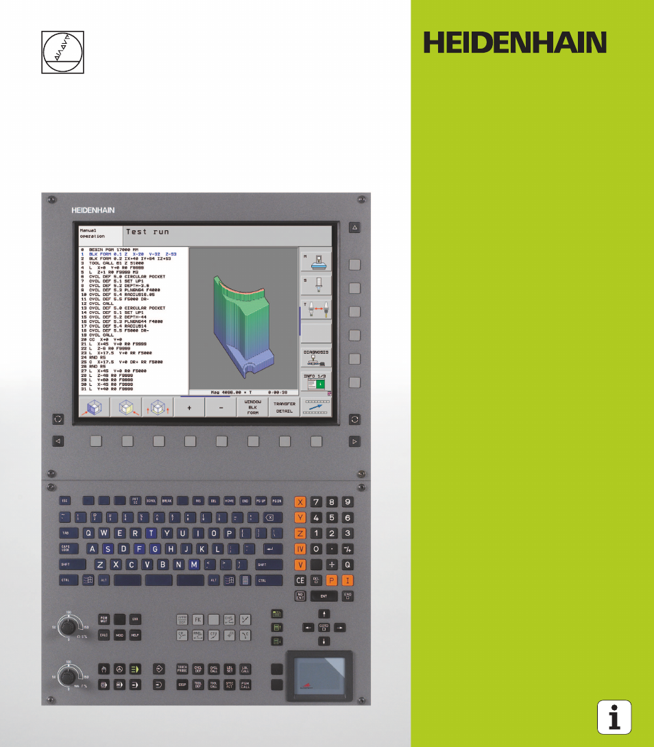
HEIDENHAIN
iTNC 530
Программное обеспечение NC
340 490-05
340 491-05
340 492-05
340 493-05
340 494-05
Русский (ru)
3/2009
- Manuals
- Brands
- HEIDENHAIN Manuals
- Control Unit
- ITNC 530 — CONVERSATIONAL PROGRAMMING
- User manual
-
Contents
-
Table of Contents
-
Bookmarks
Related Manuals for HEIDENHAIN iTNC 530
Summary of Contents for HEIDENHAIN iTNC 530
-
Page 1
User’s Manual DIN/ISO Programming iTNC 530 NC software 606 420-02 606 421-02 606 424-02 English (en) 12/2011… -
Page 2
Controls of the TNC Program/file management, TNC functions Keys on visual display unit Function Function Select or delete programs and files, external data transfer Split screen layout Define program call, select datum and point tables Toggle the display between machining and programming modes Select MOD functions Soft keys for selecting functions on… -
Page 3
Tool functions Coordinate axes and numbers: Entering and editing Function Function Define tool data in the program Select coordinate axes or . . . enter them into the program Call tool data Numbers . . . Decimal point / Reverse algebraic sign Programming path movements Function Polar coordinate input / Incremental… -
Page 5: About This Manual
Would you like any changes, or have you found any errors? We are continuously striving to improve documentation for you. Please help us by sending your requests to the following e-mail address: tnc-userdoc@heidenhain.de. HEIDENHAIN iTNC 530…
-
Page 6
TNC have the following limitations: Simultaneous linear movement in up to 4 axes HSCI (HEIDENHAIN Serial Controller Interface) identifies the new hardware platform of the TNC controls. HeROS 5 identifies the operating system of HSCI-based TNC controls. -
Page 7
User’s Manual for Cycle Programming: All of the cycle functions (touch probe cycles and fixed cycles) are described in a separate manual. Please contact HEIDENHAIN if you require a copy of this User’s Manual. ID: 670 388-xx smarT.NC user documentation: The smarT.NC operating mode is described in a separate… -
Page 8
Software options The iTNC 530 features various software options that can be enabled by you or your machine tool builder. Each option is to be enabled separately and contains the following respective functions: Software option 1 Cylinder surface interpolation (Cycles 27, 28, 29 and 39) -
Page 9
CAD Viewer software option Description Opening of 3-D models on the NC control. Page 255 Remote Desktop Manager software Description option Remote operation of external computer units Page 630 (e.g. a Windows PC) via the user interface of the TNC HEIDENHAIN iTNC 530… -
Page 10
Cross Talk Compensation software option Description (CTC) Compensation of axis couplings Machine Manual Position Adaptive Control (PAC) software Description option Changing control parameters Machine Manual Load Adaptive Control (LAC) software Description option Dynamic changing of control parameters Machine Manual… -
Page 11
Cycles full contact with the workpiece PLANE function: Entry of axis angle Page 420 User documentation as a Page 158 context-sensitive help system smarT.NC: Programming of smarT.NC Page 117 and machining can be carried out simultaneously HEIDENHAIN iTNC 530… -
Page 12
FCL 3 functions Description smarT.NC: Contour pocket on point smarT.NC Pilot pattern smarT.NC: Preview of contour smarT.NC Pilot programs in the file manager smarT.NC: Positioning strategy for smarT.NC Pilot machining point patterns FCL 2 functions Description 3-D line graphics Page 150 Virtual tool axis Page 519 USB support of block devices (memory… -
Page 13
DCM: Tool carrier management (see “Tool Holder Management (DCM Software Option)” on page 366) In the Test Run mode, the working plane can now by defined manually (see “Setting a tilted working plane for the test run” on page 544) HEIDENHAIN iTNC 530… -
Page 14
In Manual mode the RW-3D mode for position display is now also available (see “Position Display Types” on page 581) Entries in the tool table TOOL.T (see “Tool table: Standard tool data” on page 170) New DR2TABLE column for definition of a compensation table for tool radius compensation depending on the tool’s contact angle New LAST_USE column, into which the TNC enters the date and time of the last tool call… -
Page 15
In Cycle 241 «Single-Fluted Deep-Hole Drilling» it is now possible to define a dwell depth (see User’s Manual for Cycle Programming) The approach and departure behavior of Cycle 39 «Cylinder Surface Contour» can now be adjusted (see User’s Manual for Cycle Programming) HEIDENHAIN iTNC 530… -
Page 16
New Functions with 606 42x-02 New function for opening 3-D data (software option) directly on the TNC (see «Open 3-D CAD data (software option)» page 255 ff) Improvement of Dynamic Collision Monitoring (DCM): The display of stepped tools has been improved When you select tool carrier kinematics, the TNC now displays a graphical preview of the carrier kinematics (see “Assigning the tool-carrier kinematics”… -
Page 17
Exporting of tool data in CSV format (see “Export the tool data” on page 199) Marking and deleting of selectable tool data (see “Delete marked tool data” on page 200) Inserting of tool indices (see “Operating the tool management” on page 195) HEIDENHAIN iTNC 530… -
Page 18
New cycle 225 Engraving (see User’s Manual for Cycle Programming) New cycle 276 Contour Train (see User’s Manual for Cycle Programming) New cycle 290 Interpolation Turning (software option, see User’s Manual for Cycle Programming) In the thread milling cycles 26x a separate feed rate is now available for tangential approach to the thread (see User’s Manual for Cycle Programming) The following improvements were made to the KinematicsOpt… -
Page 19
(see “Position display” on page 407) The approach behavior during side finishing with Cycle 24 (DIN/ISO: G124) was changed (see User’s Manual for Cycle Programming). HEIDENHAIN iTNC 530… -
Page 20
Changed functions with 606 42x-02 Tool names can now be defined with 32 characters (see “Tool numbers and tool names” on page 168) Improved and simplified operation by mouse and touchpad in all graphics windows (see “Functions of the 3-D line graphics” on page 150) Various pop-up windows have been redesigned If you do a Test Run without calculating the machining time, the TNC… -
Page 21: Heidenhain Itnc 530
Table of Contents First Steps with the iTNC 530 Introduction Programming: Fundamentals, File Management Programming: Programming Aids Programming: Tools Programming: Programming Contours Programming: Data Transfer from DXF Files or Plain-language Contours Programming: Subprograms and Program Section Repeats Programming: Q-Parameters Programming: Miscellaneous Functions…
-
Page 23: Table Of Contents
1 First Steps with the iTNC 530 ..47 1.1 Overview ..48 1.2 Machine Switch-On ..49 Acknowledge the power interruption and move to the reference points ..49 1.3 Programming the First Part ..50 Select the correct operating mode ..50 The most important TNC keys ..
-
Page 24
Additional status displays ..77 2.5 Window Manager ..85 Soft-key row ..86 2.6 SELinux security software ..87 2.7 Accessories: HEIDENHAIN 3-D Touch Probes and Electronic Handwheels ..88 3-D touch probes ..88 HR electronic handwheels ..89… -
Page 25
Actual position capture ..101 Editing a program ..102 The TNC search function ..106 3.3 File Management: Fundamentals ..108 Files ..108 Show externally created files on the TNC ..110 Data backup ..110 HEIDENHAIN iTNC 530… -
Page 26
3.4 Working with the File Manager ..111 Directories ..111 Paths ..111 Overview: Functions of the file manager ..112 Calling the file manager ..114 Selecting drives, directories and files ..115 Creating a new directory (only possible on the drive TNC:\) ..118 Creating a new file (only possible on the drive TNC:\) .. -
Page 27
Calling the TNCguide help system ..156 Generating service files ..157 4.8 The Context-Sensitive Help System TNCguide (FCL3 Function) ..158 Function ..158 Working with the TNCguide ..159 Downloading current help files ..163 HEIDENHAIN iTNC 530… -
Page 28
5 Programming: Tools ..165 5.1 Entering Tool-Related Data ..166 Feed rate F ..166 Spindle speed S ..167 5.2 Tool Data ..168 Requirements for tool compensation ..168 Tool numbers and tool names ..168 Tool length L ..168 Tool radius R .. -
Page 29
Zero point for polar coordinates: pole I, J ..230 Straight line at rapid traverse G10 Straight line with feed rate G11 F ..230 Circular path G12/G13/G15 around pole I, J ..231 Circular path G16 with tangential connection ..232 Helical interpolation ..233 HEIDENHAIN iTNC 530… -
Page 30
7 Programming: Data Transfer from DXF Files or Plain-language Contours ..237 7.1 Processing DXF Files (Software Option) ..238 Function ..238 Opening a DXF file ..239 Basic settings ..240 Layer settings ..241 Specifying the reference point ..242 Selecting and saving a contour .. -
Page 31
Calling any program as a subprogram ..261 8.5 Nesting ..263 Types of nesting ..263 Nesting depth ..263 Subprogram within a subprogram ..264 Repeating program section repeats ..265 Repeating a subprogram ..266 8.6 Programming Examples ..267 HEIDENHAIN iTNC 530… -
Page 32
9 Programming: Q-Parameters ..273 9.1 Principle and Overview ..274 Programming notes ..276 Calling Q-parameter functions ..277 9.2 Part Families—Q Parameters in Place of Numerical Values ..278 Function ..278 9.3 Describing Contours through Mathematical Operations ..279 Function .. -
Page 33
Tilting the working plane with mathematical angles: rotary axis coordinates calculated by the TNC ..311 Measurement results from touch probe cycles (see also User’s Manual for Touch Probe Cycles) ..312 9.11 Programming Examples ..314 HEIDENHAIN iTNC 530… -
Page 34
10 Programming: Miscellaneous Functions ..321 10.1 Entering Miscellaneous Functions M and STOP ..322 Fundamentals ..322 10.2 Miscellaneous Functions for Program Run Control, Spindle and Coolant ..323 Overview ..323 10.3 Miscellaneous Functions for Coordinate Data ..324 Programming machine-referenced coordinates: M91/M92 .. -
Page 35
Activating/deactivating a function ..372 Basic rotation ..374 Swapping axes ..375 Superimposed mirroring ..376 Additional, additive datum shift ..376 Axis locking ..377 Superimposed rotation ..377 Feed rate override ..377 Handwheel superimposition ..378 HEIDENHAIN iTNC 530… -
Page 36
11.6 Adaptive Feed Control Software Option (AFC) ..380 Application ..380 Defining the AFC basic settings ..382 Recording a teach-in cut ..384 Activating/deactivating AFC ..387 Log file ..388 Tool breakage/tool wear monitoring ..390 Spindle load monitoring ..390 11.7 Creating Text Files .. -
Page 37
Selecting tilting axes: M138 ..436 Compensating the machine’s kinematics configuration for ACTUAL/NOMINAL positions at end of block: M144 (software option 2) ..437 12.5 Peripheral milling: 3-D radius compensation with workpiece orientation ..438 Function ..438 HEIDENHAIN iTNC 530… -
Page 38
13 Programming: Pallet Editor ..439 13.1 Pallet Editor ..440 Application ..440 Selecting a pallet table ..442 Leaving the pallet file ..442 Pallet datum management with the pallet preset table ..443 Executing the pallet file ..445 13.2 Pallet Operation with Tool-Oriented Machining .. -
Page 39
Managing more than one block of calibrating data ..498 14.8 Compensating Workpiece Misalignment with a 3-D Touch Probe ..499 Introduction ..499 Basic rotation using 2 points: ..501 Determining basic rotation using 2 holes/studs: ..503 Workpiece alignment using 2 points ..504 HEIDENHAIN iTNC 530… -
Page 40
14.9 Datum Setting with a 3-D Touch Probe ..505 Overview ..505 Datum setting in any axis ..505 Corner as datum – using points that were already probed for a basic rotation ..506 Corner as datum—without using points that were already probed for a basic rotation..506 Circle center as datum .. -
Page 41: Heidenhain Itnc 530
15 Positioning with Manual Data Input ..521 15.1 Programming and Executing Simple Machining Operations ..522 Positioning with Manual Data Input (MDI) ..522 Protecting and erasing programs in $MDI ..525 HEIDENHAIN iTNC 530…
-
Page 42
16 Test Run and Program Run ..527 16.1 Graphics ..528 Application ..528 Overview of display modes ..530 Plan view ..530 Projection in 3 planes ..531 3-D view ..532 Magnifying details ..535 Repeating graphic simulation ..536 Displaying the tool .. -
Page 43
Application ..581 17.11 Unit of Measurement ..582 Application ..582 17.12 Selecting the Programming Language for $MDI ..583 Application ..583 17.13 Selecting the Axes for Generating G01 Blocks ..584 Application ..584 HEIDENHAIN iTNC 530… -
Page 44
17.14 Entering the Axis Traverse Limits, Datum Display ..585 Application ..585 Working without additional traverse limits ..585 Find and enter the maximum traverse ..585 Datum display ..586 17.15 Displaying HELP Files ..587 Application ..587 Selecting HELP files .. -
Page 45
Selecting general user parameters ..598 List of general user parameters ..599 18.2 Pin Layouts and Connecting Cables for the Data Interfaces ..614 RS-232-C/V.24 interface for HEIDENHAIN devices ..614 Non-HEIDENHAIN devices ..615 RS-422/V.11 interface ..616 Ethernet interface RJ45 socket .. -
Page 46
19 Industrial PC 6341 with Windows 7 (Option) ..629 19.1 Introduction ..630 Functionality ..630 Specifications of the IPC 6341 ..630 End User License Agreement (EULA) for Windows 7 ..631 Switch to Windows interface ..631 Exiting Windows .. -
Page 47: First Steps With The Itnc 530
First Steps with the iTNC 530…
-
Page 48: Overview
The following topics are included in this chapter Machine Switch-On Programming the First Part Graphically Testing the Program Tool Setup Workpiece Setup Running the First Program First Steps with the iTNC 530…
-
Page 49: Machine Switch-On
The TNC is now ready for operation in the Manual Operation mode. Further information on this topic Traversing the reference marks: See “Switch-on” on page 460 Operating modes: See “Programming and Editing” on page 73 HEIDENHAIN iTNC 530…
-
Page 50: Programming The First Part
Soft keys on the screen with which you select functions appropriate to the active state Further information on this topic Writing and editing programs: See “Editing a program” on page 102 Overview of keys: See “Controls of the TNC” on page 2 First Steps with the iTNC 530…
-
Page 51: Create A New Program/File Management
The TNC automatically generates the first and last blocks of the program. Afterwards you can no longer change these blocks. Further information on this topic File management: See “Working with the File Manager” on page Creating a new program: See “Creating and Writing Programs” on page 97 HEIDENHAIN iTNC 530…
-
Page 52: Define A Workpiece Blank
Example NC blocks %NEW G71 * N10 G30 G17 X+0 Y+0 Z-40 * N20 G31 X+100 Y+100 Z+0 * N99999999 %NEW G71 * Further information on this topic Defining the workpiece blank: (see page 98) First Steps with the iTNC 530…
-
Page 53: Program Layout
N40 G00 G40 G90 Z+250 * Further information on this topic: N50 G200… * Cycle programming: See User’s Manual for Cycles N60 X… Y… * N70 G79 M13 * N80 G00 Z+250 M2 * N99999999 BSBCYC G71 * HEIDENHAIN iTNC 530…
-
Page 54: Program A Simple Contour
Move to contour point 3: Enter the X coordinate 95 and save your entry with the END key Define the chamfer at contour point 3: Enter the chamfer width 10 mm and save with the END key First Steps with the iTNC 530…
-
Page 55
Departure” on page 212 Programming contours: See “Overview of path functions” on page Tool radius compensation: See “Tool radius compensation” on page Miscellaneous functions (M): See “Miscellaneous Functions for Program Run Control, Spindle and Coolant” on page 323 HEIDENHAIN iTNC 530… -
Page 56: Create A Cycle Program
Confirm Radius comp.: RL/RR/no comp? by pressing the ENT key: Do not activate the radius compensation Miscellaneous function M? Enter M2 to end the program and confirm with the END key: The TNC saves the entered positioning block First Steps with the iTNC 530…
-
Page 57
N100 G00 Z+250 M2 * Retract in the tool axis, end program N99999999 %C200 G71 * Further information on this topic Creating a new program: See “Creating and Writing Programs” on page 97 Cycle programming: See User’s Manual for Cycles HEIDENHAIN iTNC 530… -
Page 58: Graphically Testing The First Program
S and is therefore active for the Test Run Press the END key: Leave the file manager Further information on this topic Tool management: See “Entering tool data in the table” on page 170 Testing programs: See “Test Run” on page 539 First Steps with the iTNC 530…
-
Page 59: Choose The Program You Want To Test
Further information on this topic Running a test run: See “Test Run” on page 539 Graphic functions: See “Graphics” on page 528 Adjusting the test speed:See “Setting the speed of the test run” on page 529 HEIDENHAIN iTNC 530…
-
Page 60: Tool Setup
To leave the tool table, press the END key Further information on this topic Operating modes of the TNC: See “Operating Modes” on page 72 Working with the tool table: See “Entering tool data in the table” on page 170 First Steps with the iTNC 530…
-
Page 61: The Pocket Table Tool_P.tch
To leave the pocket table, press the END key Further information on this topic Operating modes of the TNC: See “Operating Modes” on page 72 Working with the pocket table: See “Pocket table for tool changer” on page 182 HEIDENHAIN iTNC 530…
-
Page 62: Workpiece Setup
If you do not have a 3-D touch probe available, you have to align the workpiece so that it is fixed with its edges parallel to the machine axes. First Steps with the iTNC 530…
-
Page 63: Align The Workpiece With A 3-D Touch Probe System
NO ENT key (no transfer) Further information on this topic MDI operating mode: See “Programming and Executing Simple Machining Operations” on page 522 Workpiece alignment: See “Compensating Workpiece Misalignment with a 3-D Touch Probe” on page 499 HEIDENHAIN iTNC 530…
-
Page 64: Set The Datum With A 3-D Touch Probe
Set to 0: Press the SET DATUM soft key Press the END to close the menu Further information on this topic Datum setting: See “Datum Setting with a 3-D Touch Probe” on page 505 First Steps with the iTNC 530…
-
Page 65: Running The First Program
File management: See “Working with the File Manager” on page Start the program Press the NC start button: The TNC executes the active program Further information on this topic Running programs: See “Program Run” on page 545 HEIDENHAIN iTNC 530…
-
Page 66
First Steps with the iTNC 530… -
Page 67: Introduction
Introduction…
-
Page 68: The Itnc 530
The TNC can run all part programs that were written on HEIDENHAIN controls TNC 150 B and later. In as much as old TNC programs contain OEM cycles, the iTNC 530 must be adapted to them with the PC software CycleDesign. For more information, contact your machine tool builder or HEIDENHAIN.
-
Page 69: Visual Display Unit And Keyboard
Shift key for switchover between machining and programming modes Soft-key selection keys for machine tool builder soft keys The15-inch screen has 6 soft keys, the 19-inch screen has 18 soft keys. Switches soft-key rows for machine tool builders HEIDENHAIN iTNC 530…
-
Page 70: Sets The Screen Layout
Sets the screen layout You select the screen layout yourself: In the PROGRAMMING AND EDITING mode of operation, for example, you can have the TNC show program blocks in the left window while the right window displays programming graphics. You could also display the program structure in the right window instead, or display only program blocks in one large window.
-
Page 71: Operating Panel
The functions of the individual keys are described on the inside front cover. Some machine manufacturers do not use the standard operating panel from HEIDENHAIN. Please refer to your machine manual in these cases. Machine panel buttons, e.g. NC START or NC STOP, are also described in the manual for your machine tool.
-
Page 72: Operating Modes
2.3 Operating Modes Manual Operation and Electronic Handwheel The Manual Operation mode is required for setting up the machine tool. In this mode of operation, you can position the machine axes manually or by increments, set the datums, and tilt the working plane. The Electronic Handwheel mode of operation allows you to move the machine axes manually with the HR electronic handwheel.
-
Page 73: Programming And Editing
TNC takes into account all permanent machine components defined by the machine manufacturer as well as all measured fixtures. Soft keys for selecting the screen layout: see «Program Run, Full Sequence and Program Run, Single Block», page 74. HEIDENHAIN iTNC 530…
-
Page 74: Program Run, Full Sequence And Program Run, Single Block
Program Run, Full Sequence and Program Run, Single Block In the Program Run, Full Sequence mode of operation the TNC executes a part program continuously to its end or to a manual or programmed stop. You can resume program run after an interruption. In the Program Run, Single Block mode of operation you execute each block separately by pressing the machine START button.
-
Page 75: Status Displays
F and active M functions. Program run started. Axis is locked. Axis can be moved with the handwheel. Axes are moving under a basic rotation. Axes are moving in a tilted working plane. The M128 function or TCPM FUNCTION is active. HEIDENHAIN iTNC 530…
-
Page 76
Symbol Meaning The Dynamic Collision Monitoring function (DCM) is active. The Adaptive Feed Function (AFC) is active (software option). One or more global program settings are active (software option) Number of the active presets from the preset table. If the datum was set manually, the TNC displays the text MAN behind the symbol. -
Page 77: Additional Status Displays
With the soft keys or switch-over soft keys, you can choose directly between the available status displays. Please note that some of the status information described below is not available unless the associated software option is enabled on your TNC. HEIDENHAIN iTNC 530…
-
Page 78
Overview After switch-on, the TNC displays the Overview status form, provided that you have selected the PROGRAM+STATUS screen layout (or POSITION + STATUS). The overview form contains a summary of the most important status information, which you can also find on the various detail forms. -
Page 79
Active subprogram numbers with block number in which the subprogram was called and the label number that was called Information on standard cycles (CYC tab) Soft key Meaning No direct Active machining cycle selection possible Active values of Cycle G62 Tolerance HEIDENHAIN iTNC 530… -
Page 80
Active miscellaneous functions M (M tab) Soft key Meaning No direct List of the active M functions with fixed meaning selection possible List of the active M functions that are adapted by your machine manufacturer Introduction… -
Page 81
Oversizes (delta values) from the tool table (TAB) and the TOOL CALL (PGM) Tool life, maximum tool life (TIME 1) and maximum tool life for TOOL CALL (TIME 2) Display of the active tool and the (next) replacement tool HEIDENHAIN iTNC 530… -
Page 82
Tool measurement (TT tab) The TNC only displays the TT tab if the function is active on your machine. Soft key Meaning No direct Number of the tool to be measured selection possible Display whether the tool radius or the tool length is being measured MIN and MAX values of the individual cutting edges and the result of measuring the rotating… -
Page 83
Global program settings 2 (GPS2 tab, software option) The TNC only displays the tab if the function is active on your machine. Soft key Meaning No direct Locked axes selection possible Superimposed basic rotation Superimposed rotation Active feed rate factor HEIDENHAIN iTNC 530… -
Page 84
Adaptive Feed Control (AFC tab, software option) The TNC only displays the AFC tab if the function is active on your machine. Soft key Meaning No direct Active mode in which adaptive feed control is selection running possible Active tool (number and name) Cut number Current factor of the feed potentiomenter in percent… -
Page 85: Window Manager
The TNC shows a star in the upper left of the screen if an application of the window manager or the window manager itself has caused an error. In this case, switch to the window manager and correct the problem. If required, refer to your machine manual. HEIDENHAIN iTNC 530…
-
Page 86: Soft-Key Row
In the task bar you can also select other applications that you have started together with the TNC (switch for example to the PDF viewer or TNCguide) Click the green HEIDENHAIN symbol to open a menu in which you can get information, make settings or start applications. The following functions are available:…
-
Page 87: Selinux Security Software
Files created anew by other programs must basically not be run. There are only two procedures permitted to run new files: Starting a software update A HEIDENHAIN software update can replace or change system files. Starting the SELinux configuration The configuration of SELinux is usually password-protected by your machine tool builder.
-
Page 88: Accessories: Heidenhain 3-D Touch Probes And Electronic Handwheels
2.7 Accessories: HEIDENHAIN 3-D Touch Probes and Electronic Handwheels 3-D touch probes With the various HEIDENHAIN 3-D touch probe systems you can: Automatically align workpieces Quickly and precisely set datums Measure the workpiece during program run Measure and inspect tools All of the touch probe functions are described in the User’s Manual for Cycles.
-
Page 89: Hr Electronic Handwheels
Electronic handwheels facilitate moving the axis slides precisely by hand. A wide range of traverses per handwheel revolution is available. Apart from the HR130 and HR150 integral handwheels, HEIDENHAIN also offers the HR 520 and HR 550 FS portable handwheels. You will find a detailed description of HR 520 in Chapter 14 of this manual (see “Traversing with electronic handwheels”…
-
Page 90
Introduction… -
Page 91: Programming: Fundamentals, File Management
Programming: Fundamentals, File Management…
-
Page 92: Fundamentals
3.1 Fundamentals Position encoders and reference marks The machine axes are equipped with position encoders that register the positions of the machine table or tool. Linear axes are usually equipped with linear encoders, rotary tables and tilting axes with angle encoders.
-
Page 93: Reference System On Milling Machines
X direction, and the index finger in the positive Y direction. The iTNC 530 can control up to 18 axes. The axes U, V and W are secondary linear axes parallel to the main axes X, Y and Z, respectively.
-
Page 94: Polar Coordinates
Polar coordinates If the production drawing is dimensioned in Cartesian coordinates, you also write the NC program using Cartesian coordinates. For parts containing circular arcs or angles it is often simpler to give the dimensions in polar coordinates. While the Cartesian coordinates X, Y and Z are three-dimensional and can describe points in space, polar coordinates are two-dimensional and describe points in a plane.
-
Page 95: Absolute And Incremental Workpiece Positions
G91 Y = 10 mm G91 Y = 10 mm Absolute and incremental polar coordinates Absolute polar coordinates always refer to the pole and the reference axis. Incremental coordinates always refer to the last programmed nominal position of the tool. HEIDENHAIN iTNC 530…
-
Page 96: Setting The Datum
The fastest, easiest and most accurate way of setting the datum is by using a 3-D touch probe from HEIDENHAIN. See “Setting the Datum with a 3-D Touch Probe” in the Touch Probe Cycles User’s Manual.
-
Page 97: Creating And Writing Programs
The last block of a program is identified by N99999999 the program name and the active unit of measure. Danger of collision! After each tool call, HEIDENHAIN recommends always traversing to a safe position, from which the TNC can position the tool for machining without causing a collision!
-
Page 98: Creating A New Part Program
Creating a new part program You always enter a part program in the Programming and Editing mode of operation. An example of program initiation: Select the Programming and Editing operating mode. Press the PGM MGT key to call the file manager. Select the directory in which you wish to store the new program: FILE NAME = OLD.H Enter the new program name and confirm your entry…
-
Page 99
Working spindle axis X/Y/Z by pressing the DEL key! The TNC can display the graphics only if the shortest side is at least 50 µm long and the longest side is no longer than 99 999.999 mm. HEIDENHAIN iTNC 530… -
Page 100: Programming Tool Movements In Din/Iso Format
Programming tool movements in DIN/ISO format To program a block, select a DIN/ISO function key on the alphabetic keyboard. You can also use the gray contouring keys to get the corresponding G code. You only need to make sure that capitalization is active. Example of a positioning block Start block.
-
Page 101: Actual Position Capture
(e.g. for radius compensation), then the TNC also closes the soft-key row for axis selection. The actual-position-capture function is not allowed if the tilted working plane function is active. HEIDENHAIN iTNC 530…
-
Page 102: Editing A Program
Editing a program You cannot edit a program while it is being run by the TNC in a machine operating mode. The TNC allows you to place the cursor in the block, but it does not save the changes and responds instead with an error message. While you are creating or editing a part program, you can select any desired line in the program or individual words in a block with the arrow keys or the soft keys:…
-
Page 103
To accept the change, press the END key. If you want to insert a word, press the horizontal arrow key repeatedly until the desired dialog appears. You can then enter the desired value. HEIDENHAIN iTNC 530… -
Page 104
Looking for the same words in different blocks To use this function, set the AUTO DRAW soft key to OFF. To select a word in a block, press the arrow keys repeatedly until the highlight is on the desired word. Select a block with the arrow keys. -
Page 105
To end the marking function, press the CANCEL SELECTION soft key. Function Soft key Switch the marking function on. Switch the marking function off. Delete the marked block. Insert the block that is stored in the buffer memory. Copy the marked block. HEIDENHAIN iTNC 530… -
Page 106: The Tnc Search Function
The TNC search function With the search function of the TNC, you can search for any text within a program and replace it by a new text, if required. Searching for texts If required, select the block containing the word you wish to find. Select the search function.
-
Page 107
REPLACE soft key. To replace all text occurrences, press the REPLACE ALL soft key. To skip the text and move to its next occurrence press the DO NOT REPLACE soft key. End the search function HEIDENHAIN iTNC 530… -
Page 108: File Management: Fundamentals
3.3 File Management: Fundamentals Files Files in the TNC Type Programs In HEIDENHAIN format In DIN/ISO format smarT.NC files Structured unit program Contour descriptions Point tables for machining positions Tables for Tools Tool changers .TCH Pallets Datums Points .PNT Presets Cutting data .CDT…
-
Page 109
0 1 2 3 4 5 6 7 8 9 . _ — You should not use any other characters in file names in order to prevent any file transfer problems. The maximum limit for the path and file name together is 82 characters (see “Paths” on page 111). HEIDENHAIN iTNC 530… -
Page 110: Show Externally Created Files On The Tnc
We recommend saving newly written programs and files on a PC at regular intervals. The TNCremoNT data transmission freeware from HEIDENHAIN is a simple and convenient method for backing up data stored on the TNC. You additionally need a data medium on which all machine-specific data, such as the PLC program, machine parameters, etc., are stored.
-
Page 111: Working With The File Manager
AUFTR1 directory, the directory NCPROG was created and the part program PROG1.H was copied into it. The part program now has the following path: TNC:\AUFTR1\NCPROG\PROG1.H The chart at right illustrates an example of a directory display with different paths. HEIDENHAIN iTNC 530…
-
Page 112: Overview: Functions Of The File Manager
Overview: Functions of the file manager If you want to use the old file management system, you must use the MOD function to switch to the old file manager (see “Changing the PGM MGT setting” on page 575). Function Soft key Page Copy (and convert) individual files Page 119…
-
Page 113
Function Soft key Page Manage network drives. Page 139 Copy a directory. Page 122 Update the directory tree, e.g. to be able to see if a new directory was created while the file manager was opened. HEIDENHAIN iTNC 530… -
Page 114: Calling The File Manager
Calling the file manager Press the PGM MGT key: The TNC displays the file management window (see figure for default setting. If the TNC displays a different screen layout, press the WINDOW soft key.) The narrow window on the left shows the available drives and directories.
-
Page 115: Selecting Drives, Directories And Files
To select a drive, press the SELECT soft key, or Press the ENT key. Step 2: Select a directory Move the highlight to the desired directory in the left-hand window— the right-hand window automatically shows all files stored in the highlighted directory HEIDENHAIN iTNC 530…
-
Page 116
Step 3: Select a file Press the SELECT TYPE soft key Press the soft key for the desired file type, or Press the SHOW ALL soft key to display all files, or Use wild card characters, e.g. to show all files of the 4*.H file type .H that begin with 4 Move the highlight to the desired file in the right window:… -
Page 117
Shift the soft-key row. Select the submenu for selecting the editor. Open the .HU or .HC program with the conversational editor. Open the .HU program with the smarT.NC editor. Open the .HC program with the smarT.NC editor. HEIDENHAIN iTNC 530… -
Page 118: Creating A New Directory (Only Possible On The Drive Tnc:\)
Creating a new directory (only possible on the drive TNC:\) Move the highlight in the left window to the directory in which you want to create a subdirectory. Enter the new directory name, and confirm with ENT. CREATE \NEW DIRECTORY? Press the YES soft key to confirm, or Abort with the NO soft key.
-
Page 119: Copying A Single File
ENT key or the OK soft key: the TNC copies the file to the selected directory. The original file is retained. When the copying process has been started with ENT or the OK soft key, the TNC displays a pop-up window with a progress indicator. HEIDENHAIN iTNC 530…
-
Page 120: Copying Files Into Another Directory
Copying files into another directory Select a screen layout with two equally sized windows. To display directories in both windows, press the PATH soft key. In the right window Move the highlight to the directory into which you wish to copy the files, and display the files in this directory with the ENT key.
-
Page 121: Copying A Table
Or, if you press the REPLACE FIELDS soft key, the TNC merely overwrites the first 10 lines of the number, length and radius columns in the TOOL.T file. The data of the other lines and columns is not changed. HEIDENHAIN iTNC 530…
-
Page 122: Copying A Directory
Copying a directory In order to copy directories, you must have set the view so that the TNC displays directories in the window on the right (see “Adapting the file manager” on page 128). Please note that when copying directories, the TNC only copies those files that are displayed by the current filter settings.
-
Page 123: Deleting A File
To select the erasing function, press the DELETE soft key. The TNC inquires whether you really intend to delete the directory and all its subdirectories and files To confirm, press the YES soft key; To cancel deletion, press the NO soft key. HEIDENHAIN iTNC 530…
-
Page 124: Marking Files
Marking files Marking function Soft key Move cursor upward Move cursor downward Tag a single file Tag all files in the directory Untag a single file Untag all files Copy all tagged files Programming: Fundamentals, File Management…
-
Page 125
To mark further files, press the TAG FILE soft key, etc. To copy the tagged files, press the COPY TAG soft key, or Delete the tagged files by pressing END to end the marking function, and then the DELETE soft key to delete the tagged files. HEIDENHAIN iTNC 530… -
Page 126: Renaming A File
Tagging files with shortcuts Move the highlight to the first file Press and hold the CTRL key. Use the arrow keys to move the cursor frame to other files Press the spacebar to tag a file. When you have tagged all desired files: release the CTRL key and perform the desired file operation.
-
Page 127: Additional Functions
Search for a USB device. In order to remove the USB device, move the cursor to the USB device. Remove the USB device. For more information: See “USB devices on the TNC (FCL 2 function)” on page 140. HEIDENHAIN iTNC 530…
-
Page 128
Adapting the file manager You open the menu for adapting the file manager either by clicking the path name or with soft keys: Select the file manager: Press the PGM MGT key Select the third soft-key row Press the MORE FUNCTIONS soft key Press the OPTIONS soft key: the TNC displays the menu for adapting the file manager Use the arrow keys to move the highlight to the desired setting… -
Page 129: Working With Shortcuts
Disconnect USB device (see also ”USB devices on the TNC (FCL 2 function)” on page 140) SHIFT + UP or DOWN arrow key: Mark several files or directories (see also ”Marking files” on page 124) ESC key: Cancel the function. HEIDENHAIN iTNC 530…
-
Page 130: Archive Files
Archive files You can use the TNC archiving function to save files and directories in a ZIP archive. You can open the ZIP archives externally using standard programs. The TNC packs all the marked files and directories into the desired ZIP archive. TNC packs TNC-specific files (e.g. plain-language programs) in an internal format (binary format), so you must observe the points below: You might not be able to open packed files with an…
-
Page 131: Extract Files From Archive
Select the desired target directory Confirm with the OK soft key and the TNC extracts the archive The TNC always extracts the files to the target directory you have selected. If the archive contains directories, the TNC creates subdirectories for them. HEIDENHAIN iTNC 530…
-
Page 132: Additional Tools For Management Of External File Types
Additional tools for management of external file types With the additional tools you can display or edit various externally created file types on the TNC. File types Description PDF files (pdf) Page 132 Excel tables (xls, csv) Page 133 Internet files (htm, html) Page 133 ZIP archive (zip) Page 134…
-
Page 133
Mozilla Firefox is provided under Help. To exit Mozilla Firefox, proceed as follows: Use the mouse to select the File menu item. Select the menu item Quit: The TNC returns to the file manager. HEIDENHAIN iTNC 530… -
Page 134
Working with ZIP archives To open ZIP archives with the extension zip directly on the TNC, proceed as follows: Call the file manager Select the directory in which the archive file is saved Move the highlight to the archive file Press ENT: The TNC opens the archive file in its own application using the Xarchiver additional tool With the key combination ALT+TAB you can always return to the TNC… -
Page 135
(STRG+C, STRG+V,…), are available within Mousepad. To exit Mousepad, proceed as follows: Use the mouse to select the File menu item. Select the menu item Quit : The TNC returns to the file manager. HEIDENHAIN iTNC 530… -
Page 136
Displaying Image Files To open image files with the extension bmp, gif, jpg or png directly on the TNC, proceed as follows: Call the file manager Select the directory in which the image file is saved Move the highlight to the image file Press ENT: The TNC opens the image file in its own application using the ristretto additional tool With the key combination ALT+TAB you can always return to the TNC… -
Page 137: Data Transfer To Or From An External Data Medium
Moves the highlight from the left to the right window, and vice versa. If you wish to copy from the TNC to the external data medium, move the highlight in the left window to the file to be transferred. HEIDENHAIN iTNC 530…
-
Page 138
If you wish to copy from the external data medium to the TNC, move the highlight in the right window to the file to be transferred. To select another drive or directory: press the soft key for choosing the directory. The TNC opens a pop-up window. -
Page 139: The Tnc In A Network
TNC displays [READ DIR] to indicate that a connection is being established. The maximum transmission speed is 2 to 5 Mbps, depending on the type of file being transferred and how busy the network is. HEIDENHAIN iTNC 530…
-
Page 140: Usb Devices On The Tnc (Fcl 2 Function)
In theory, you should be able to connect all USB devices with the file systems mentioned above to the TNC. If you nevertheless encounter problems, please contact HEIDENHAIN. The USB devices appear as separate drives in the directory tree, so you can use the file-management functions described in the earlier chapters correspondingly.
-
Page 141
TNC removes the USB device from the directory tree. Exit the file manager. In order to re-establish a connection with a USB device that has been removed, press the following soft key: Select the function for reconnection of USB devices. HEIDENHAIN iTNC 530… -
Page 142
Programming: Fundamentals, File Management… -
Page 143: Programming: Programming Aids
Programming: Programming Aids…
-
Page 144: Adding Comments
4.1 Adding Comments Function You can add comments to any desired block in the part program to explain program steps or make general notes. If the TNC cannot show the entire comment on the screen, the >> sign is displayed. The last character in a comment block must not have any tilde (~).
-
Page 145: Functions For Editing Of The Comment
Jump to end of comment. Jump to the beginning of a word. Words must be separated by a space. Jump to the end of a word. Words must be separated by a space. Switch between insert mode and overwrite mode. HEIDENHAIN iTNC 530…
-
Page 146: Structuring Programs
4.2 Structuring Programs Definition and applications This TNC function enables you to comment part programs in structuring blocks. Structuring blocks are short texts with up to 37 characters and are used as comments or headlines for the subsequent program lines. With the aid of appropriate structuring blocks, you can organize long and complex programs in a clear and comprehensible manner.
-
Page 147: Integrated Pocket Calculator
Superimpose the on-line calculator by pressing the CALC key and perform the desired calculation Press the actual-position-capture key for the TNC to transfer the calculated value into the active input box and to close the calculator HEIDENHAIN iTNC 530…
-
Page 148: Programming Graphics
4.4 Programming Graphics Generating / not generating graphics during programming While you are writing the part program, you can have the TNC generate a 2-D pencil-trace graphic of the programmed contour. To switch the screen layout to displaying program blocks to the left and graphics to the right, press the SPLIT SCREEN key and PGM + GRAPHICS soft key.
-
Page 149: Block Number Display On/Off
Enlarge the frame overlay—press and hold the soft key to magnify the detail Confirm the selected area with the WINDOW DETAIL soft key. With the WINDOW BLK FORM soft key, you can restore the original section. HEIDENHAIN iTNC 530…
-
Page 150: D Line Graphics (Fcl2 Function)
4.5 3-D Line Graphics (FCL2 Function) Function Use the 3-D line graphics to have the TNC show the programmed traverse paths in three dimensions. A powerful zoom function is available for recognizing details quickly. You should especially use the 3-D line graphics to inspect programs created externally for irregularities before machining, in order to avoid undesirable traces of the machining process on the workpiece.
-
Page 151
Show workpiece in the last active view Show/hide programmed end points with a dot on the line Do or do not highlight the selected NC block of the 3-D line graphics in the left window Do or do not show block numbers HEIDENHAIN iTNC 530… -
Page 152: Highlighting Nc Blocks In The Graphics
You can also use the mouse with the 3-D line graphics. The following functions are available: In order to rotate the wire model shown in three dimensions: Hold the right mouse button down and move the mouse. The TNC displays a coordinate system showing the currently active orientation of the workpiece.
-
Page 153: Immediate Help For Nc Error Messages
Read the cause of error and any suggestions for possible remedies. The TNC may show additional information that can be helpful to trained HEIDENHAIN personnel during troubleshooting. Close the Help window with the CE key, thus canceling the error message.
-
Page 154: List Of All Current Error Messages
4.7 List of All Current Error Messages Function With this function you can show a pop-up window in which the TNC shows all current error messages. The TNC shows errors both from the NC as well as those from the machine tool builder. Show error list You can call the list as soon as at least one error message is present: To display the list, press the ERR key…
-
Page 155: Window Contents
Window contents Column Meaning Number Error number (–1: no error number defined), issued by HEIDENHAIN or your machine tool builder Error class. Defines how the TNC processes Class this error. ERROR Collective error class for errors that can cause various error reactions depending on…
-
Page 156: Calling The Tncguide Help System
MANUFACTURER soft key with which you can call this separate help system. There you will find further, more detailed information on the error message concerned. Call the help for HEIDENHAIN error messages. Call the help for HEIDENHAIN error messages, if available. Programming: Programming Aids…
-
Page 157: Generating Service Files
The service file contains all NC data needed for troubleshooting. By passing on the service file you declare your consent to your machine tool builder or DR. JOHANNES HEIDENHAIN GmbH to use these data for diagnostic purposes. The maximum size of a service file is 40 MB…
-
Page 158: The Context-Sensitive Help System Tncguide (Fcl3 Function)
The English and German documentation is shipped as standard with each NC software level. HEIDENHAIN provides the remaining conversational languages for cost-free download as soon as the respective translations are available (see “Downloading current help files”…
-
Page 159: Working With The Tncguide
Use the arrow keys to move the cursor to the block Press the HELP key: The TNC starts the help system and shows a description for the active function (does not apply to miscellaneous functions or cycles that were integrated by your machine tool builder) HEIDENHAIN iTNC 530…
-
Page 160: Table Of Contents
Navigating in the TNCguide It’s easiest to use the mouse to navigate in the TNCguide. A table of contents appears on the left side of the screen. By clicking the rightward pointing triangle you open subordinate sections, and by clicking the respective entry you open the individual pages. It is operated in the same manner as the Windows Explorer.
-
Page 161
The focus is switched internally to the TNC application so that you can operate the control when the TNCguide is open. If the full screen is active, the TNC reduces the window size automatically before the change of focus Close the TNCguide HEIDENHAIN iTNC 530… -
Page 162: Programming: Programming Aids
Subject index The most important subjects in the Manual are listed in the subject index (Index tab). You can select them directly by mouse or with the cursor keys. The left side is active. Select the Index tab Activate the Keyword input field Enter the word for the desired subject and the TNC synchronizes the index and creates a list in which you can find the subject more easily, or…
-
Page 163: Downloading Current Help Files
Downloading current help files You’ll find the help files for your TNC software on the HEIDENHAIN home page www.heidenhain.de under: Services and Documentation Documentation / Information User Documentation TNCguide Select the desired language, for example English: You will see a ZIP…
-
Page 164
Language TNC directory Chinese (simplified) TNC:\tncguide\zh Chinese (traditional) TNC:\tncguide\zh-tw Slovenian (software option) TNC:\tncguide\sl Norwegian TNC:\tncguide\no Slovak TNC:\tncguide\sk Latvian TNC:\tncguide\lv Korean TNC:\tncguide\kr Estonian TNC:\tncguide\et Turkish TNC:\tncguide\tr Romanian TNC:\tncguide\ro Lithuanian TNC:\tncguide\lt Programming: Programming Aids… -
Page 165: Programming: Tools
Programming: Tools…
-
Page 166: Entering Tool-Related Data
5.1 Entering Tool-Related Data Feed rate F The feed rate F is the speed (in millimeters per minute or inches per minute) at which the tool center point moves. The maximum feed rates can be different for the individual axes and are set in machine parameters.
-
Page 167: Spindle Speed S
To program the spindle speed, press the S key on the alphabetic keyboard. Enter the new spindle speed. Changing during program run You can adjust the spindle speed during program run with the spindle- speed override knob S. HEIDENHAIN iTNC 530…
-
Page 168: Tool Data
5.2 Tool Data Requirements for tool compensation You usually program the coordinates of path contours as they are dimensioned in the workpiece drawing. To allow the TNC to calculate the tool center path—i.e. the tool compensation—you must also enter the length and radius of each tool you are using. Tool data can be entered either directly in the part program with G99 or separately in a tool table.
-
Page 169: Delta Values For Lengths And Radii
Tool radius: Compensation value for the tool radius In the programming dialog, you can transfer the value for tool length and tool radius directly into the input line by pressing the desired axis soft key. Example N40 G99 T5 L+10 R+5 * HEIDENHAIN iTNC 530…
-
Page 170: Entering Tool Data In The Table
When transferring tool tables to older software versions of the iTNC 530 or to older TNC controls, you must make sure that tool names are not longer than 16 characters, because otherwise they will be truncated accordingly by the TNC when read in. This can lead to errors in connection with the Replacement Tool function.
-
Page 171
Input range: 0 to 99999 minutes Comment on the tool. Tool description? Input range: 16 characters max. Information on this tool that is to be sent to the PLC. PLC status? Input range: 8 characters bit-coded HEIDENHAIN iTNC 530… -
Page 172
Abbr. Inputs Dialog PLC-VAL Value of this tool that is to be sent to the PLC. PLC value? Input range: -99999.9999 to +99999.9999 PTYP Tool type for evaluation in the pocket table. Tool type for pocket table? Input range: 0 to +99 NMAX Limits the spindle speed for this tool. -
Page 173
LAST_USE Date and time at which the TNC inserted the tool for the last time Date/time of last tool call? via TOOL CALL. Input range: 16 characters max., format internally specified: Date = yyyy.mm.dd, time = hh.mm HEIDENHAIN iTNC 530… -
Page 174
Tool table: Tool data required for automatic tool measurement For a description of the cycles for automatic tool measurement, see the User’s Manual for Cycle Programming. Abbr. Inputs Dialog Number of teeth (99 teeth maximum) Number of teeth? Input range: 0 to 99 Permissible deviation from tool length L for wear detection. -
Page 175
Permissible deviation from tool radius R for breakage detection. If Breakage tolerance: radius? the entered value is exceeded, the TNC locks the tool (status L). Input range: 0 to 0.9999 mm Input range in mm: 0 to 0.9999 Input range in inches: 0 to +0.03936 HEIDENHAIN iTNC 530… -
Page 176
Tool table: Tool data for automatic speed/feed rate calculation Abbr. Inputs Dialog TYPE Tool type: Press the ASSIGN TYPE soft key (3rd soft-key row); the Tool type? TNC superimposes a window where you can select the type of tool. Functions are currently only assigned to the DRILL and MILL tool types TMAT Tool material: Press the ASSIGN MATERIAL soft key (3rd soft-key… -
Page 177
Select previous page in table Select next page in table Look for the tool name in the table Show tool information in columns or show all information on one tool on one screen page Move to beginning of line HEIDENHAIN iTNC 530… -
Page 178
Editing functions for tool tables Soft key Move to end of line Copy highlighted field Insert copied field Add the entered number of lines (tools) at the end of the table Insert a line for the indexed tool number after the active line. -
Page 179
The target file must exist The file to be copied must contain only the columns (or lines) you want to replace To copy individual columns or lines, press the REPLACE FIELDS soft key (see “Copying a single file” on page 119). HEIDENHAIN iTNC 530… -
Page 180: Tool-Carrier Kinematics
HEIDENHAIN provides tool-carrier kinematics for HEIDENHAIN touch probes. If required, please contact HEIDENHAIN. Assigning the tool-carrier kinematics Follow the procedure below to assign carrier kinematics to a tool:…
-
Page 181: Using An External Pc To Overwrite Individual Tool Data
Using an external PC to overwrite individual tool data The HEIDENHAIN data transfer software TNCremoNT provides an especially convenient way to use an external PC to overwrite tool data (see “Software for data transfer” on page 567). This applies when you measure tool data on an external tool presetter and then want to transfer the data to the TNC.
-
Page 182: Pocket Table For Tool Changer
Pocket table for tool changer The machine tool builder adapts the functional range of the pocket table to the requirements of your machine. The machine tool manual provides further information. For automatic tool changing you need the pocket table TOOL_P.TCH. The TNC can manage several pocket tables with any file names.
-
Page 183
Lock the pocket at left? Box magazine: Lock the pocket at right LOCKED_RIGHT Lock the pocket at right? S1 … S5 Function is defined by the machine tool builder. The machine tool Value? documentation provides further information. HEIDENHAIN iTNC 530… -
Page 184
Editing functions for pocket tables Soft key Select beginning of table Select end of table Select previous page in table Select next page in table Reset pocket table Reset tool number column T Go to beginning of next line Reset column to original state. Only applies to the columns RSV, LOCKED_ABOVE, LOCKED_BELOW, LOCKED_LEFT and LOCKED_RIGHT Programming: Tools… -
Page 185: Calling Tool Data
Tool length oversize DL: Enter the delta value for the tool length. Tool radius oversize DR: Enter the delta value for the tool radius. Tool radius oversize DR2: Enter the delta value for the tool radius 2. HEIDENHAIN iTNC 530…
-
Page 186
Editing tool data in the selection window In the pop-up window for tool selection you can also edit the displayed tool data: Use the arrow keys to select the line and then the column of the value to be edited: The light-blue background marks the editable field Set the EDIT soft key to ON, enter the desired value and confirm with the ENT key… -
Page 187
Tool preselection with tool tables If you are working with tool tables, use G51 to preselect the next tool. Simply enter the tool number or a corresponding Q parameter, or type the tool name in quotation marks. HEIDENHAIN iTNC 530… -
Page 188: Tool Change
Tool change The tool change function can vary depending on the individual machine tool. The machine tool manual provides further information. Tool change position The tool change position must be approachable without collision. With the miscellaneous functions M91 and M92, you can enter machine- based (rather than workpiece-based) coordinates for the tool change position.
-
Page 189
If the radii are not equal, the TNC displays an error message and does not replace the tool. On NC programs without radius compensation the TNC does not check the tool radius of the replacement tool during the change. HEIDENHAIN iTNC 530… -
Page 190: Tool Usage Test
Tool usage test The tool usage test function must be enabled by your machine manufacturer. Refer to your machine tool manual. The following are prerequisites for a tool usage test: Bit 2 of the machine parameter must be set to 7246=1 The machining timer must be active in the Test Run operating mode A simulation of the plain language program must have been completed in the Test Run mode…
-
Page 191
Tool name from the tool table Tool-usage time in seconds (feed time) TIME WTIME Tool-usage time in seconds (total usage time between tool changes) Tool radius R + Oversize of tool radius DR from the tool table. The unit is 0.1 µm. HEIDENHAIN iTNC 530… -
Page 192
Column Meaning BLOCK Block number in which the TOOL CALL block was programmed TOKEN = TOOL: Path name of the active main PATH program or subprogram TOKEN = STOTAL: Path name of the subprogram Tool number with tool index Maximum feed rate override that occurred OVRMAX during machining. -
Page 193: Tool Management (Software Option)
Select the tool table: Press the TOOL TABLE soft key Scroll through the soft-key row Select the TOOL MANAGEMENT soft key: The TNC goes into the new table view (see figure at right) HEIDENHAIN iTNC 530…
-
Page 194
In the new view, the TNC presents all tool information in the following four card registers: Tools: Tool specific information Tool pockets: Pocket-specific information Tooling list: List of all tools in the NC program that is selected in the Program Run mode (only if you have already created a tool usage file, see «Tool usage test», page 190). -
Page 195
Define the settings: SORT COLUMN active: Click the column header to sort the content of the column MOVE COLUMN active: The column can be shifted by drag and drop Reset manual settings (shifted columns) to original condition HEIDENHAIN iTNC 530… -
Page 196
In addition, you can perform the following functions by mouse: Sorting function By clicking a column of the table head, you sort the data in ascending or descending order (depending on the active setting). Moving columns You can arrange the columns in any sequence you want by clicking a column of the table head and then moving it with the mouse key pressed down. -
Page 197
Copy the tool data of the selected tool (2nd soft- key row) Insert the copied tool data in the selected tool (2nd soft-key row) Select/deselect check boxes (e.g. for TL line) Open selection lists of combo boxes (e.g. for AFC line) HEIDENHAIN iTNC 530… -
Page 198
Import tool data Using this function you can simply import tool data that you have measured externally on a presetting device, for example. The file to be imported must have the CSV format (comma separated value). The CSV file format describes the structure of a text file for exchanging simply structured data. -
Page 199
Start the export procedure with the START soft key: The TNC shows the status of the export procedure in a pop-up window Terminate the export procedure by pressing the END key or soft key The TNC always stores the exported CSV file in the TNC:\system\tooltab directory. HEIDENHAIN iTNC 530… -
Page 200
Delete marked tool data You can use this function you can simply delete tool data that you no longer need. Follow the steps outlined below for deleting: In the tool management you use the arrow keys or mouse to mark the tool data that you wish to delete Select the DELETE MARKED TOOLS soft key and the TNC shows a pop-up window listing the tool data to be deleted… -
Page 201: Tool Compensation
L from the G99 block or tool table is the oversize for length DL in the T 0 block (not TOOL CALL taken into account by the position display). is the oversize for length DL in the tool table. HEIDENHAIN iTNC 530…
-
Page 202: Tool Radius Compensation
Tool radius compensation The NC block for programming a tool movement contains: G41 or G42 for radius compensation G43 or G44, for radius compensation in single-axis movements G40 if there is no radius compensation Radius compensation becomes effective as soon as a tool is called and is moved with a straight line block in the working plane with G41 or G42.
-
Page 203
G42/G41 or canceled with G40 the TNC always positions the tool perpendicular to the programmed starting or end position. Position the tool at a sufficient distance from the first or last contour point to prevent the possibility of damaging the contour. HEIDENHAIN iTNC 530… -
Page 204
Entering radius compensation Radius compensation is entered in a G01 block: To select tool movement to the left of the programmed contour, select function G41, or To select tool movement to the right of the contour, select function G42, or To select tool movement without radius compensation or to cancel radius compensation, select function G40… -
Page 205
Machining corners without radius compensation If you program the tool movement without radius compensation, you can change the tool path and feed rate at workpiece corners with the miscellaneous function M90. see «Smoothing corners: M90», page 327. HEIDENHAIN iTNC 530… -
Page 206
Programming: Tools… -
Page 207: Programming: Programming Contours
Programming: Programming Contours…
-
Page 208: Tool Movements
6.1 Tool Movements Path functions A workpiece contour is usually composed of several contour elements such as straight lines and circular arcs. With the path functions, you can program the tool movements for straight lines and circular arcs. Miscellaneous functions M With the TNC’s miscellaneous functions you can affect The program run, e.g., a program interruption The machine functions, such as switching spindle rotation and…
-
Page 209: Fundamentals Of Path Functions
The tool retains the Z coordinate and moves in the XY plane to the position X=70, Y=50 (see figure). Three-dimensional movement The program block contains three coordinates. The TNC thus moves the tool in space to the programmed position. Example: N50 G01 X+80 Y+0 Z-10 * HEIDENHAIN iTNC 530…
-
Page 210
Entering more than three coordinates The TNC can control up to 5 axes simultaneously (software option). Machining with 5 axes, for example, moves 3 linear and 2 rotary axes simultaneously. Such programs are too complex to program at the machine, however, and are usually created with a CAM system. -
Page 211
You cannot activate radius compensation in a circle block. Activate it beforehand in a straight-line block (see «Path Contours—Cartesian Coordinates», page 216). Pre-positioning Before running a part program, always pre-position the tool to prevent the possibility of damaging it or the workpiece. HEIDENHAIN iTNC 530… -
Page 212: Contour Approach And Departure
6.3 Contour Approach and Departure Starting point and end point The tool approaches the first contour point from the starting point. The starting point must be: Programmed without radius compensation Approachable without danger of collision Close to the first contour point Example Figure at upper right: If you set the starting point in the dark gray area, the contour will be damaged when the first contour element is…
-
Page 213
Example Figure at upper right: If you set the starting point in the dark gray area, the contour will be damaged when the first contour element is approached. HEIDENHAIN iTNC 530… -
Page 214: Tangential Approach And Departure
Tangential approach and departure With G26 (figure at top right), you can program a tangential approach to the workpiece, and with G27 (figure at lower right) a tangential departure. In this way you can avoid dwell marks. Starting point and end point The starting point and the end point lie outside the workpiece, close to the first and last contour points.
-
Page 215
Tangential approach with radius R = 5 mm . . . PROGRAM CONTOUR BLOCKS Last contour point . . . Tangential departure with radius R = 5 mm N210 G27 R5 * End point N220 G00 G40 X-30 Y+50 * HEIDENHAIN iTNC 530… -
Page 216: Path Contours—Cartesian Coordinates
6.4 Path Contours—Cartesian Coordinates Overview of path functions Function Path function key Tool movement Required input Page Line L Straight line Coordinates of the end Page 217 points of the straight line Chamfer CHF Chamfer between two Chamfer side length Page 218 straight lines Circle Center CC…
-
Page 217: Straight Line At Rapid Traverse G00 Straight Line With Feed Rate G01 F
TNC generates an L block with the actual position coordinates. In the MOD function, you define the number of axes that the TNC saves in a G01 block (see «Selecting the Axes for Generating G01 Blocks», page 584). HEIDENHAIN iTNC 530…
-
Page 218: Inserting A Chamfer Between Two Straight Lines
Inserting a chamfer between two straight lines The chamfer enables you to cut off corners at the intersection of two straight lines. The line blocks before and after the G24 block must be in the same working plane as the chamfer The radius compensation before and after the G24 block must be the same The chamfer must be machinable with the current tool…
-
Page 219: Corner Rounding G25
A feed rate programmed in the G25 block is effective only in that G25 block. After the G25 block, the previous feed rate becomes effective again. You can also use an RND block for a tangential contour approach. HEIDENHAIN iTNC 530…
-
Page 220: Circle Center I, J
Circle center I, J You can define a circle center for circles that you have programmed with the G02, G03 or G05 function. This is done in the following ways: Entering the Cartesian coordinates of the circle center in the working plane, or Using the circle center defined in an earlier block, or Capturing the coordinates with the ACTUAL-POSITION-CAPTURE…
-
Page 221: Circular Path C Around Circle Center Cc
For the end point, enter the same point that you used for the starting point. The starting and end points of the arc must lie on the circle. Input tolerance: up to 0.016 mm (selected with MP7431). Smallest possible circle that the TNC can traverse: 0.0016 µm. HEIDENHAIN iTNC 530…
-
Page 222: Circular Path G02/G03/G05 With Defined Radius
Circular path G02/G03/G05 with defined radius The tool moves on a circular path with the radius R. Direction of rotation In clockwise direction: G02 In counterclockwise direction: G03 Without programmed direction: G05. The TNC traverses the circular arc with the last programmed direction of rotation Coordinates of the arc end point Radius R Note: The algebraic sign determines the size of the…
-
Page 223
The maximum radius that can be entered directly is 99.9999 m, with Q parameter programming 210 m. You can also enter rotary axes A, B and C. HEIDENHAIN iTNC 530… -
Page 224: Circular Path G06 With Tangential Connection
Circular path G06 with tangential connection The tool moves on an arc that starts tangentially to the previously programmed contour element. A transition between two contour elements is called tangential when there is no kink or corner at the intersection between the two contours—the transition is smooth.
-
Page 225
N160 G27 R5 F500 * Tangential exit N170 G40 X-20 Y-20 F1000 * Retract tool in the working plane, cancel radius compensation N180 G00 Z+250 M2 * Retract in the tool axis, end program N99999999 %LINEAR G71 * HEIDENHAIN iTNC 530… -
Page 226
Example: Circular movements with Cartesian coordinates %CIRCULAR G71 * Define blank form for graphic workpiece simulation N10 G30 G17 X+0 Y+0 Z-20 * N20 G31 G90 X+100 Y+100 Z+0 * Call tool in the spindle axis and with the spindle speed S N40 T1 G17 S4000 * N50 G00 G40 G90 Z+250 * Retract tool in the spindle axis at rapid traverse… -
Page 227
Depart the contour on a circular arc with tangential connection N190 G40 X-20 Y-20 F1000 * Retract tool in the working plane, cancel radius compensation N200 G00 Z+250 M2 * Retract tool in the tool axis, end of program N99999999 %CIRCULAR G71 * HEIDENHAIN iTNC 530… -
Page 228
Example: Full circle with Cartesian coordinates %C-CC G71 * N10 G30 G17 X+0 Y+0 Z-20 * Definition of workpiece blank N20 G31 G90 X+100 Y+100 Z+0 * N40 T1 G17 S3150 * Tool call N50 G00 G40 G90 Z+250 * Retract the tool N60 I+50 J+50 * Define the circle center… -
Page 229: Path Contours—Polar Coordinates
Helical interpolation Combination of a circular and Polar radius, polar angle of Page 233 a linear movement the arc end point, coordinate of the end point in the tool axis HEIDENHAIN iTNC 530…
-
Page 230: Zero Point For Polar Coordinates: Pole I, J
Zero point for polar coordinates: pole I, J You can define the pole CC anywhere in the part program before blocks containing polar coordinates. Set the pole in the same way as you would program the circle center. Coordinates: Enter Cartesian coordinates for the pole or, if you want to use the last programmed position, enter G29.
-
Page 231: Circular Path G12/G13/G15 Around Pole I, J
Polar-coordinates angle H: Angular position of the arc end point between –99 999.9999° and +99 999.9999° Direction of rotation DR Example NC blocks N180 I+25 J+25 * N190 G11 G42 R+20 H+0 F250 M3 * N200 G13 H+180 * HEIDENHAIN iTNC 530…
-
Page 232: Circular Path G16 With Tangential Connection
Circular path G16 with tangential connection The tool moves on a circular path, starting tangentially from a preceding contour element. Polar coordinate radius R: Enter the distance from are end point to the pole I, J Polar coordinates angle H: Angular position of the arc end point Example NC blocks N120 I+40 J+35 *…
-
Page 233: Helical Interpolation
The table below illustrates in which way the shape of the helix is determined by the work direction, direction of rotation and radius compensation. Work Direction of Radius Internal thread direction rotation comp. Right-handed Left-handed Right-handed Z– Left-handed Z– External thread Right-handed Left-handed Right-handed Z– Left-handed Z– HEIDENHAIN iTNC 530…
-
Page 234
Programming a helix Always enter the same algebraic sign for the direction of rotation and the incremental total angle G91 H. The tool may otherwise move in a wrong path and damage the contour. For the total angle G91 H you can enter a value of -99 999.9999°… -
Page 235
N170 G27 R5 F500 * N180 G40 R+60 H+180 F1000 * Retract tool in the working plane, cancel radius compensation N190 G00 Z+250 M2 * Retract in the spindle axis, end of program N99999999 %LINEARPO G71 * HEIDENHAIN iTNC 530… -
Page 236
Example: Helix %HELIX G71 * N10 G30 G17 X+0 Y+0 Z-20 * Definition of workpiece blank N20 G31 G90 X+100 Y+100 Z+0 * N40 T1 G17 S1400 * Tool call N50 G00 G40 G90 Z+250 * Retract the tool Pre-position the tool N60 X+50 Y+50 * Transfer the last programmed position as the pole N70 G29 *… -
Page 237: Programming: Data Transfer From Dxf Files Or Plain-Language Contours
Programming: Data Transfer from DXF Files or Plain-language Contours…
-
Page 238: Processing Dxf Files (Software Option)
7.1 Processing DXF Files (Software Option) Function DXF files created in a CAD system can be opened directly by the TNC, in order to extract contours or machining positions, and save them as conversational programs or as point files. Plain-language programs acquired in this manner can also be run by older TNC controls, since these contour programs contain only L and CC/C blocks.
-
Page 239: Opening A Dxf File
Select the desired DXF file, and load it with the ENT key. The TNC starts the DXF converter and shows the contents of the DXF file on the screen. The TNC shows the layers in the left window, and the drawing in the right window. HEIDENHAIN iTNC 530…
-
Page 240: Basic Settings
Basic settings The third soft-key row has various possibilities for settings: Setting Soft key COLOR NORMAL/INVERTED: Changing the color scheme 3-D MODE/2-D MODE: Change between 2-D and 3-D mode UNIT OF MEASURE MM/INCH: Enter the unit of measurement of the DXF file. The TNC then outputs the contour program in this unit of measurement.
-
Page 241: Layer Settings
To hide a layer, select the layer with the left mouse button, and click its check box to hide it To show a layer, select the layer with the left mouse button, and click its check box again to show it HEIDENHAIN iTNC 530…
-
Page 242: Specifying The Reference Point
Specifying the reference point The datum of the drawing for the DXF file is not always located in a manner that lets you use it directly as a reference point for the workpiece. Therefore, the TNC has a function with which you can shift the drawing datum to a suitable location by clicking an element.
-
Page 243
If the TNC cannot calculate an intersection, it rescinds the marking of the first element. Element information At the bottom left of the screen, the TNC shows how far the reference point you haven chosen is located from the drawing datum. HEIDENHAIN iTNC 530… -
Page 244: Selecting And Saving A Contour
Selecting and saving a contour You must use the touchpad on the TNC keyboard or a mouse attached via the USB port in order to select a contour. If you are not using the contour program in the smarT.NC operating mode, you must specify the machining sequence when selecting the contour that it matches the desired machining direction.
-
Page 245
The TNC only saves elements that have actually been selected (blue elements), which means that they have been given a check mark in the left window. HEIDENHAIN iTNC 530… -
Page 246
Dividing, extending and shortening contour elements If contour elements to be selected in the drawing connect poorly, then you must first divide the contour element. This function is automatically available if you are in the mode for selecting a contour. Proceed as follows: The poorly connecting contour element is selected, so it is colored blue. -
Page 247: Selecting And Storing Machining Positions
Quick selection of hole positions by entering a diameter: By entering a hole diameter, you can select all hole positions with that diameter in the DXF file (see “Quick selection of hole positions by entering a diameter” on page 250) HEIDENHAIN iTNC 530…
-
Page 248
Individual selection Select the mode for choosing a machining position. The TNC hides the layers shown in the left window, and the right window becomes active for position selection. In order to select a machining position, click the desired element with the left mouse button. The TNC indicates possible locations for machining positions on the selected element with stars. -
Page 249
DXF file is also saved. If you want to select more machining positions in order to save them in a different file, press the CANCEL SELECTED ELEMENTS soft key and select as described above HEIDENHAIN iTNC 530… -
Page 250
Quick selection of hole positions by entering a diameter Select the mode for choosing a machining position. The TNC hides the layers shown in the left window, and the right window becomes active for position selection. Select the last soft-key row. Open the dialog for diameter input: enter any diameter in the pop-up window displayed by the TNC. -
Page 251
With the apply path optimization option on (default setting), the TNC sorts the selected machining positions for the most efficient possible tool path. You can have the tool path displayed by clicking the SHOW TOOL PATH soft key (see “Basic settings” on page 240). HEIDENHAIN iTNC 530… -
Page 252
Element information At the bottom left of the screen, the TNC displays the coordinates of the machining position that you last selected via mouse click in the left or right window. Undoing actions You can undo the four most recent actions that you have taken in the mode for selecting machining positions. -
Page 253: Zoom Function
The zooming center is the location of the mouse pointer. Alternatively you can zoom by selecting a zoom area with the left mouse button. A double-click with the right mouse button resets the view to the default setting. HEIDENHAIN iTNC 530…
-
Page 254: Data Transfer From Plain-Language Programs
7.2 Data transfer from plain- language programs Application Using this function you can take contour sections or complete contours from existing plain-language programs, especially those created with CAM systems. The TNC shows the plain-language dialogs in two-dimensional or three-dimensional form. It is particularly efficient to use data transfer in conjunction with the smartWizard, which provides contour editing UNITs for 2-D and 3-D processing.
-
Page 255: Open 3-D Cad Data (Software Option)
NC programs or other files. This permits you to check quickly and simply for problems directly in the 3-D model. . The TNC currently supports the following types of file formats: STEP files (file extension STP) IGES files (file extension IGS or IGES) HEIDENHAIN iTNC 530…
-
Page 256: Operate Cad Viewer
Operate CAD viewer Function Soft key Show shaded model. Show wire model Show wire model without invisible edges Adapt display size to screen size Select standard 3-D view Select plan view Select view from below Select view from left Select view from right Select view from front Select view from behind Mouse functions…
-
Page 257: Programming: Subprograms And Program Section Repeats
Programming: Subprograms and Program Section Repeats HEIDENHAIN iTNC 530…
-
Page 258: Labeling Subprograms And Program Section Repeats
8.1 Labeling Subprograms and Program Section Repeats Subprograms and program section repeats enable you to program a machining sequence once and then run it as often as desired. Labels The beginnings of subprograms and program section repeats are marked in a part program by labels (G98 L). A LABEL is identified by a number between 1 and 999 or by a name you define.
-
Page 259: Subprograms
Press the QS soft key; the TNC will then jump to the label name that is specified in the string parameter defined. G98 L 0 is not permitted (Label 0 is only used to mark the end of a subprogram). HEIDENHAIN iTNC 530…
-
Page 260: Program Section Repeats
8.3 Program Section Repeats Label G98 The beginning of a program section repeat is marked by the label G98 L. The end of a program section repeat is identified by Ln,m. Operating sequence 1 The TNC executes the part program up to the end of the program section (Ln,m) 2 Then the program section between the called LBL Ln,m is repeated the number of times entered for m…
-
Page 261: Separate Program As Subprogram
CALL PGM block. Conclude this function with the END key. Alternatively you can also enter the program name or the complete path name of the program to be called directly via the keyboard. HEIDENHAIN iTNC 530…
-
Page 262
The program you are calling must be stored on the hard disk of your TNC. You need only enter the program name if the program you want to call is located in the same directory as the program you are calling it from. If the called program is not located in the same directory as the program you are calling it from, you must enter the complete path, e.g. -
Page 263: Nesting
Maximum nesting depth for subprograms: 8 Maximum nesting depth for main program calls: 10, where a G79 acts like a main program call You can nest program section repeats as often as desired HEIDENHAIN iTNC 530…
-
Page 264: Subprogram Within A Subprogram
Subprogram within a subprogram Example NC blocks %SUBPGMS G71 * N17 L «SP1»,0 * Subprogram at label G98 L SP1 is called Last program block of the N35 G00 G40 Z+100 M2 * main program (with M2) Beginning of subprogram SP1 N36 G98 L «SP1″…
-
Page 265: Repeating Program Section Repeats
4 Program section between block 15 and block 35 is repeated once (including the program section repeat between 20 and block 27) 5 Main program REPS is executed from block 36 to block 50 (end of program). HEIDENHAIN iTNC 530…
-
Page 266: Repeating A Subprogram
Repeating a subprogram Example NC blocks %SUBPGREP G71 * N10 G98 L1 * Beginning of program section repeat 1 Subprogram call N11 L2,0 * Program section between this block and G98 L1 N12 L1,2 * (block N10) is repeated twice Last block of the main program with M2 N19 G00 G40 Z+100 M2 * Beginning of subprogram…
-
Page 267: Programming Examples
Tool call N50 G00 G40 G90 Z+250 * Retract the tool N60 I+50 J+50 * Set pole N70 G10 R+60 H+180 * Pre-position in the working plane N80 G01 Z+0 F1000 M3 * Pre-position to the workpiece surface HEIDENHAIN iTNC 530…
-
Page 268
N90 G98 L1 * Set label for program section repeat N100 G91 Z-4 * Infeed depth in incremental values (in space) N110 G11 G41 G90 R+45 H+180 F250 * First contour point N120 G26 R5 * Contour approach N130 H+120 * N140 H+60 * N150 H+0 * N160 H-60 *… -
Page 269
N50 G00 G40 G90 Z+250 * Cycle definition: drilling N60 G200 DRILLING Q200=2 ;SET-UP CLEARANCE Q201=-30 ;DEPTH Q206=300 ;FEED RATE FOR PLNGNG Q202=5 ;PLUNGING DEPTH Q210=0 ;DWELL TIME AT TOP Q203=+0 ;SURFACE COORDINATE Q204=2 ;2ND SET-UP CLEARANCE Q211=0 ;DWELL TIME AT DEPTH HEIDENHAIN iTNC 530… -
Page 270
N70 X+15 Y+10 M3 * Move to starting point for group 1 N80 L1.0 * Call the subprogram for the group N90 X+45 Y+60 * Move to starting point for group 2 N100 L1.0 * Call the subprogram for the group N110 X+75 Y+10 * Move to starting point for group 3 N120 L1.0 *… -
Page 271
;DEPTH Q206=250 ;FEED RATE FOR PLNGNG Q202=3 ;PLUNGING DEPTH Q210=0 ;DWELL TIME AT TOP Q203=+0 ;SURFACE COORDINATE Q204=10 ;2ND SET-UP CLEARANCE Q211=0.2 ;DWELL TIME AT DEPTH N90 L1,0 * Call subprogram 1 for the entire hole pattern HEIDENHAIN iTNC 530… -
Page 272
N100 G00 Z+250 M6 * Tool change N110 T2 G17 S4000 * Call tool: drill N120 D0 Q201 P01 -25 * New depth for drilling N130 D0 Q202 P01 +5 * New plunging depth for drilling N140 L1.0 * Call subprogram 1 for the entire hole pattern N150 G00 Z+250 M6 * Tool change N160 T3 G17 S500 *… -
Page 273: Programming: Q-Parameters
Programming: Q-Parameters…
-
Page 274: Principle And Overview
9.1 Principle and Overview You can program entire families of parts in a single part program. You do this by entering variables called Q parameters instead of fixed numerical values. Q parameters can represent information such as: Coordinate values Feed rates Spindle speeds Cycle data Q parameters also enable you to program contours that are defined…
-
Page 275
In principle, the same ranges are available for QS parameters as for Q parameters (see table above). Note that for the QS parameters the QS100 to QS199 range is reserved for internal texts. HEIDENHAIN iTNC 530… -
Page 276: Programming Notes
Programming notes You can mix Q parameters and fixed numerical values within a program. Q parameters can be assigned numerical values between 999 999 999 and +999 999 999, meaning that up to nine digits plus the algebraic sign are permitted. You can set the decimal point at any position. Internally, the TNC can calculate up to a range of 57 bits before and 7 bits after the decimal point (32-bit data width corresponds to a decimal value of 4 294 967 296).
-
Page 277: Calling Q-Parameter Functions
Q key in any dialog, and then press the L on the ASCII keyboard. In order to define or assign QR nonvolatile parameters, first press the Q key in any dialog, and then press the R on the ASCII keyboard. HEIDENHAIN iTNC 530…
-
Page 278: Part Families—Q Parameters In Place Of Numerical Values
9.2 Part Families—Q Parameters in Place of Numerical Values Function The Q parameter function D0: ASSIGN assigns numerical values to Q parameters. This enables you to use variables in the program instead of fixed numerical values. Example NC blocks N150 D00 Q10 P01 +25 * Assignment Q10 is assigned the value 25 N250…
-
Page 279: Describing Contours Through Mathematical Operations
To the right of the “=” character you can enter the following: Two numbers Two Q parameters A number and a Q parameter The Q parameters and numerical values in the equations can be entered with positive or negative signs. HEIDENHAIN iTNC 530…
-
Page 280: Programming Fundamental Operations
Programming fundamental operations Example: Program blocks in the TNC Example: N17 D00 Q5 P01 +10 * Call the Q parameter functions by pressing the Q key N17 D03 Q12 P01 +Q5 P02 +7 * To select the mathematical functions, press the BASIC ARITHMETIC soft key To select the Q parameter function ASSIGN, press the D0 X = Y soft key…
-
Page 281: Trigonometric Functions
α = arc tan (a / b) = arc tan (sin α / cos α) Example: a = 25 mm b = 50 mm α = arctan (a / b) = arctan 0.5 = 26.57° Furthermore: a² + b² = c² (where a² = a x a) (a² + b²) HEIDENHAIN iTNC 530…
-
Page 282: Programming Trigonometric Functions
Programming trigonometric functions Press the ANGLE FUNCTION soft key to call the trigonometric functions. The TNC then displays the following soft keys: Programming: Compare “Example: Programming fundamental operations.” Function Soft key D06: SINE Example: D06 Q20 P01 -Q5 * Calculates and assigns the sine of an angle in degrees (°) D07: COSINE Example: D07 Q21 P01 -Q5 *…
-
Page 283: If-Then Decisions With Q Parameters
To call another program as a subprogram, enter a % program call after the block with the target label. Unconditional jumps An unconditional jump is programmed by entering a conditional jump whose condition is always true. Example: D09 P01 +10 P02 +10 P03 1 * HEIDENHAIN iTNC 530…
-
Page 284: Programming If-Then Decisions
Programming If-Then decisions There are 3 possibilities to enter the jump address: Label number, selectable via LBL NUMBER soft key Label number, selectable via LBL NAME soft key String number, selectable via QS soft key Press the JUMP soft key to call the If-Then conditions. The TNC then displays the following soft keys: Function Soft key…
-
Page 285: Checking And Changing Q Parameters
If you want to check or edit local, global or string parameters, press the SHOW PARAMETERS Q QL QR QS soft key. The TNC then displays all respective parameters and the above described also apply. HEIDENHAIN iTNC 530…
-
Page 286: Additional Functions
9.7 Additional Functions Overview Press the DIVERSE FUNCTION soft key to call the additional functions. The TNC then displays the following soft keys: Function Soft key Page D14:ERROR Page 287 Output of error messages D15:PRINT Page 291 Unformatted output of texts or Q parameter values D19:PLC Page 292…
-
Page 287: D14: Error: Displaying Error Messages
With the function D14 you can call messages under program control. The messages are predefined by the machine tool builder or by HEIDENHAIN. Whenever the TNC comes to a block with D14 in the Program Run or Test Run mode, it interrupts the program run and displays a message.
-
Page 288
Error number Text 1016 Contradictory input 1017 CYCL incomplete 1018 Plane wrongly defined 1019 Wrong axis programmed 1020 Wrong rpm 1021 Radius comp. undefined 1022 Rounding-off undefined 1023 Rounding radius too large 1024 Program start undefined 1025 Excessive nesting 1026 Angle reference missing 1027 No fixed cycle defined… -
Page 289
TCHPROBE 430: diameter too small 1064 No measuring axis defined 1065 Tool breakage tolerance exceeded 1066 Enter Q247 unequal to 0 1067 Enter Q247 greater than 5 1068 Datum table? 1069 Enter Q351 unequal 0 1070 Thread depth too large HEIDENHAIN iTNC 530… -
Page 290
Error number Text 1071 Missing calibration data 1072 Tolerance exceeded 1073 Block scan active 1074 ORIENTATION not permitted 1075 3-D ROT not permitted 1076 Activate 3-D ROT 1077 Enter a negative value for the depth 1078 Q303 not defined in measuring cycle 1079 Tool axis not allowed 1080… -
Page 291: D15 Print: Output Of Texts Or Q Parameter Values
Application example: Recording workpiece measurement. You can transfer up to six Q parameters and numerical values simultaneously. The TNC separates them with slashes. Example: Output of dialog text 1 and numerical value for Q1 N70 D15 P01 1 P02 Q1 * HEIDENHAIN iTNC 530…
-
Page 292: D19 Plc: Transfer Values To The Plc
D19 PLC: Transfer values to the PLC The function D19 transfers up to two numerical values or Q parameters to the PLC. Increments and units: 0.1 µm or 0.0001° Example: Transfer the numerical value 10 (which means 1 µm or 0.001°) to the PLC N56 D19 P01 +10 P02 +Q3 * Programming: Q-Parameters…
-
Page 293: Entering Formulas Directly
Inverse of the sine. Determines the angle from the ratio of the side opposite the hypotenuse. Example: Q10 = ASIN 0.75 Arc cosine Inverse of the cosine. Determines the angle from the ratio of the side adjacent to the hypotenuse. Example: Q11 = ACOS Q40 HEIDENHAIN iTNC 530…
-
Page 294
Mathematical function Soft key Arc tangent Inverse of the tangent. Determines the angle from the ratio of the opposite to the adjacent side. Example: Q12 = ATAN Q50 Powers of values Example: Q15 = 3^3 Constant “pi” (3.14159) Example: Q15 = PI Natural logarithm (LN) of a number Base 2.7183 Example: Q15 = LN Q11… -
Page 295: Rules For Formulas
1st calculation: 10 squared = 100 2ndcalculation: 3 to the power of 3 = 27 3rdcalculation: 100 – 27 = 73 Distributive law Law for calculating with parentheses a * (b + c) = a * b + a * c HEIDENHAIN iTNC 530…
-
Page 296: Programming Example
Programming example Calculate an angle with the arc tangent from the opposite side (Q12) and adjacent side (Q13); then store in Q25. To select the formula entering function, press the Q key and the FORMULA soft key, or use the shortcut: Press the Q key on the ASCII keyboard.
-
Page 297: String Parameters
Comparing alphabetic priority Page 307 When you use a STRING FORMULA, the result of the arithmetic operation is always a string. When you use the FORMULA function, the result of the arithmetic operation is always a numeric value. HEIDENHAIN iTNC 530…
-
Page 298: Assigning String Parameters
Assigning string parameters You have to assign a string variable before you use it. Use the DECLARE STRING command to do so. Show the soft-key row with special functions. Select the menu for defining various plain-language functions Select string functions Select the DECLARE STRING function Example NC block: N37 DECLARE STRING QS10 = “WORKPIECE”…
-
Page 299: Chain-Linking String Parameters
Conclude with the END key Example: QS10 is to include the complete text of QS12, QS13 and QS14 N37 QS10 = QS12 || QS13 || QS14 Parameter contents: QS12: Workpiece QS13: Status: QS14: Scrap QS10: Workpiece Status: Scrap HEIDENHAIN iTNC 530…
-
Page 300: Converting A Numerical Value To A String
Converting a numerical value to a string parameter With the TOCHAR function, the TNC converts a numerical value to a string parameter. This enables you to chain numerical values with string variables. Select Q parameter functions Select the STRING FORMULA function Select the function for converting a numerical value to a string parameter Enter the number or the desired Q parameter to be…
-
Page 301: Copying A Substring From A String Parameter
Remember that the first character of a text sequence starts internally with the zeroth place. Example: A four-character substring (LEN4) is read from the string parameter QS10 beginning with the third character (BEG2) N37 QS13 = SUBSTR ( SRC_QS10 BEG2 LEN4 ) HEIDENHAIN iTNC 530…
-
Page 302: Copying System Data To A String Parameter
Copying system data to a string parameter With the SYSSTR function you can copy system data to a string parameter. At present only reading of the system time is available. Select Q-parameter functions Select the STRING FORMULA function Enter the number of the string parameter in which the TNC is to save the copied string.
-
Page 303
10: D.MM.YY 11: YYYY-MM-DD 12: YY-MM-DD 13: hh:mm:ss 14: h:mm:ss 15: h:mm Example: read out the current system time in the format DD.MM.YYYY hh:mm:ss, and save it in parameter QS13. N70 QS13 = SYSSTR ( ID321 NR0) HEIDENHAIN iTNC 530… -
Page 304: Converting A String Parameter To A Numerical Value
Converting a string parameter to a numerical value The TONUMB function converts a string parameter to a numerical value. The value to be converted should be only numerical. The QS parameter must contain only one numerical value. Otherwise the TNC will output an error message. Select Q-parameter functions Select the FORMULA function Enter the number of the string parameter in which the…
-
Page 305: Checking A String Parameter
Example: Search through QS10 for the text saved in parameter QS13. Begin the search at the third place. N37 Q50 = INSTR ( SRC_QS10 SEA_QS13 BEG2 ) HEIDENHAIN iTNC 530…
-
Page 306: Finding The Length Of A String Parameter
Finding the length of a string parameter The STRLEN function returns the length of the text saved in a selectable string parameter. Select Q-parameter functions Select the FORMULA function Enter the number of the Q parameter in which the TNC is to save the ascertained string length. Confirm with the ENT key Shift the soft-key row Select the function for finding the text length of a…
-
Page 307: Comparing Alphabetic Priority
+1: The first QS parameter precedes the second QS parameter alphabetically. –1: The first QS parameter follows the second QS parameter alphabetically. Example: QS12 and QS14 are compared for alphabetic priority N37 Q52 = STRCOMP ( SRC_QS12 SEA_QS14 ) HEIDENHAIN iTNC 530…
-
Page 308: Preassigned Q Parameters
9.10 Preassigned Q Parameters The Q parameters Q100 to Q199 are assigned values by the TNC. The following are assigned to Q parameters: Values from the PLC Tool and spindle data Data on operating status Results of measurements from touch probe cycles etc. Do not use preassigned Q parameters (or QS parameters) between Q100 and Q199 (QS100 and QS199) as calculation parameters in NC programs.
-
Page 309: Tool Axis: Q109
M5 after M4 Q110 = 3 Coolant on/off: Q111 M function Parameter value M8: Coolant ON Q111 = 1 M9: Coolant OFF Q111 = 0 Overlap factor: Q112 The overlap factor for pocket milling (MP7430) is assigned to Q112. HEIDENHAIN iTNC 530…
-
Page 310: Unit Of Measurement For Dimensions In The Program: Q113
Unit of measurement for dimensions in the program: Q113 During nesting the PGM CALL, the value of the parameter Q113 depends on the dimensional data of the program from which the other programs are called. Dimensional data of the main program Parameter value Metric system (mm) Q113 = 0…
-
Page 311: Deviation Between Actual Value And Nominal Value During Automatic Tool Measurement With The Tt 130
Deviation of actual from nominal value Parameter value Tool length Q115 Tool radius Q116 Tilting the working plane with mathematical angles: rotary axis coordinates calculated by the Coordinates Parameter value A axis Q120 B axis Q121 C axis Q122 HEIDENHAIN iTNC 530…
-
Page 312: Measurement Results From Touch Probe Cycles (See Also User’s Manual For Touch Probe Cycles)
Measurement results from touch probe cycles (see also User’s Manual for Touch Probe Cycles) Measured actual values Parameter value Angle of a straight line Q150 Center in the reference axis Q151 Center in the minor axis Q152 Diameter Q153 Pocket length Q154 Pocket width Q155…
-
Page 313
Number of the last active measuring cycle Q198 Status of tool measurement with TT Parameter value Tool within tolerance Q199 = 0.0 Tool is worn (LTOL/RTOL is exceeded) Q199 = 1.0 Tool is broken (LBREAK/RBREAK is Q199 = 2.0 exceeded) HEIDENHAIN iTNC 530… -
Page 314: Programming Examples
9.11 Programming Examples Example: Ellipse Program sequence The contour of the ellipse is approximated by many short lines (defined in Q7). The more calculation steps you define for the lines, the smoother the curve becomes. The machining direction can be altered by changing the entries for the starting and end angles in the plane: Clockwise machining direction:…
-
Page 315
N380 G73 G90 H+0 * Reset the rotation N390 G54 X+0 Y+0 * Reset the datum shift N400 G00 G40 Z+Q12 * Move to set-up clearance N410 G98 L0 * End of subprogram N99999999 %ELLIPSE G71 * HEIDENHAIN iTNC 530… -
Page 316
Example: Concave cylinder machined with spherical cutter Program sequence This program functions only with a spherical cutter. The tool length refers to the sphere center. The contour of the cylinder is approximated by many short line segments (defined in Q13). The more line segments you define, the smoother the curve becomes. -
Page 317
Unfinished? If not finished, return to LBL 1 N430 G98 L99 * N440 G73 G90 H+0 * Reset the rotation N450 G54 X+0 Y+0 Z+0 * Reset the datum shift N460 G98 L0 * End of subprogram N99999999 %CYLIN G71 * HEIDENHAIN iTNC 530… -
Page 318
Example: Convex sphere machined with end mill Program sequence This program requires an end mill. The contour of the sphere is approximated by many short lines (in the Z/X plane, defined in Q14). The smaller you define the angle increment, the smoother the curve becomes. You can determine the number of contour cuts through the angle increment in the plane (defined in Q18). -
Page 319
N470 D09 P01 +Q28 P02 +Q9 P03 1 * N480 G73 G90 H+0 * Reset the rotation N490 G54 X+0 Y+0 Z+0 * Reset the datum shift N500 G98 L0 * End of subprogram N99999999 %SPHERE G71 * HEIDENHAIN iTNC 530… -
Page 320
Programming: Q-Parameters… -
Page 321: Programming: Miscellaneous Functions
Programming: Miscellaneous Functions…
-
Page 322: Entering Miscellaneous Functions M And Stop
10.1 Entering Miscellaneous Functions M and STOP Fundamentals With the TNC’s miscellaneous functions—also called M functions— you can affect the program run, e.g., a program interruption the machine functions, such as switching spindle rotation and coolant supply on and off the path behavior of the tool The machine tool builder may add some M functions that are not described in this User’s Manual.
-
Page 323: Miscellaneous Functions For Program Run Control, Spindle And Coolant
Clear the status display (depends on MP7300) Spindle ON clockwise Spindle ON counterclockwise Spindle STOP Tool change Spindle STOP Program run STOP (depends on MP7440) Coolant ON Coolant OFF Spindle ON clockwise Coolant ON Spindle ON counterclockwise Coolant ON Same as M2 HEIDENHAIN iTNC 530…
-
Page 324: Miscellaneous Functions For Coordinate Data
10.3 Miscellaneous Functions for Coordinate Data Programming machine-referenced coordinates: M91/M92 Scale reference point On the scale, a reference mark indicates the position of the scale reference point. Machine datum The machine datum is required for the following tasks: Defining the limits of traverse (software limit switches) Moving to machine-referenced positions (such as tool change positions) Setting the workpiece datum…
-
Page 325
In order to be able to graphically simulate M91/M92 movements, you need to activate working space monitoring and display the workpiece blank referenced to the set datum (see «Showing the Workpiece in the Working Space», page 578). HEIDENHAIN iTNC 530… -
Page 326: Activating The Most Recently Entered Datum: M104
Activating the most recently entered datum: M104 Function When processing pallet tables, the TNC may overwrite your most recently entered datum with values from the pallet table. With M104 you can reactivate the original datum. Effect M104 is effective only in the blocks in which it is programmed. M104 becomes effective at the end of block.
-
Page 327: Miscellaneous Functions For Contouring Behavior
Insert rounding arc between straight lines: M112 Compatibility For reasons of compatibility, the M112 function is still available. However, to define the tolerance for fast contour milling, HEIDENHAIN recommends the use of the TOLERANCE cycle (see User’s Manual for Cycles, section 32 TOLERANCE). HEIDENHAIN iTNC 530…
-
Page 328: Do Not Include Points When Executing Non-Compensated Line Blocks: M124
Do not include points when executing non- compensated line blocks: M124 Standard behavior The TNC runs all line blocks that have been entered in the active program. Behavior with M124 When running non-compensated line blocks with very small point intervals, you can use parameter T to define a minimum point interval up to which the TNC will not include points during execution.
-
Page 329: Machining Small Contour Steps: M97
(LOOK AHEAD): M120” on page 335). Effect M97 is effective only in the blocks in which it is programmed. A corner machined with M97 will not be completely finished. You may wish to rework the contour with a smaller tool. HEIDENHAIN iTNC 530…
-
Page 330
Example NC blocks N50 T20 G01 …* Tool with large tool radius N130 X … Y … F … M97 * Move to contour point 13 N140 G91 Y-0.5 … F … * Machine small contour step 13 to 14 N150 X+100 … -
Page 331: Machining Open Contours Corners: M98
M98 takes effect at the end of block. Example NC blocks Move to the contour points 10, 11 and 12 in succession: N100 G01 G41 X … Y … F … * N110 X … G91 Y … M98 * N120 X+ … * HEIDENHAIN iTNC 530…
-
Page 332: Feed Rate Factor For Plunging Movements: M103
Feed rate factor for plunging movements: M103 Standard behavior The TNC moves the tool at the last programmed feed rate, regardless of the direction of traverse. Behavior with M103 The feed rate reduction with M103 is only effective if bit 4 in MP7440 has been set to 1.
-
Page 333: Feed Rate In Millimeters Per Spindle Revolution: M136
F in millimeters per spindle revolution. If you change the spindle speed by using the spindle override, the TNC changes the feed rate accordingly. Effect M136 becomes effective at the start of block. You can cancel M136 by programming M137. HEIDENHAIN iTNC 530…
-
Page 334: Feed Rate For Circular Arcs: M109/M110/M111
Feed rate for circular arcs: M109/M110/M111 Standard behavior The TNC applies the programmed feed rate to the path of the tool center. Behavior at circular arcs with M109 The TNC adjusts the feed rate for circular arcs at inside and outside contours so that the feed rate at the tool cutting edge remains constant.
-
Page 335: Calculating The Radius-Compensated Path In Advance (Look Ahead): M120
M120 LA0 is programmed, or M120 is programmed without LA, or another program is called with % the working plane is tilted with Cycle G80 or the PLANE function M120 becomes effective at the start of block. HEIDENHAIN iTNC 530…
-
Page 336
Restrictions After an external or internal stop, you can only re-enter the contour with the function RESTORE POS. AT N. Before you start the block scan, you must cancel M120 (select program again via PGM MGT, do not use GOTO 0), otherwise the TNC will output an error message When using the path functions G25 and G24, the blocks before and after G25 or G24 must contain only… -
Page 337: Superimposing Handwheel Positioning During Program Run: M118
M118 also functions in the Positioning with MDI mode of operation! M118 in combination with DCM collision monitoring is only possible in stopped condition (blinking control-in- operation symbol). If you try to move an axis during handwheel superimposition, the TNC will generate an error message. HEIDENHAIN iTNC 530…
-
Page 338: Retraction From The Contour In The Tool-Axis Direction: M140
Retraction from the contour in the tool-axis direction: M140 Standard behavior In the program run modes, the TNC moves the tool as defined in the part program. Behavior with M140 With M140 MB (move back) you can enter a path in the direction of the tool axis for departure from the contour.
-
Page 339: Suppressing Touch Probe Monitoring: M141
If you use M141, make sure that you retract the touch probe in the correct direction. M141 functions only for movements with straight-line blocks. Effect M141 is effective only in the block in which it is programmed. M141 becomes effective at the start of the block. HEIDENHAIN iTNC 530…
-
Page 340: Delete Modal Program Information: M142
Delete modal program information: M142 Standard behavior The TNC resets modal program information in the following situations: Select a new program Execute a miscellaneous function M2, M30, or an N99999999 %..block (depending on MP7300) Defining cycles for basic behavior with a new value Behavior with M142 All modal program information except for basic rotation, 3-D rotation and Q parameters is reset.
-
Page 341: Automatically Retract Tool From The Contour At An Nc Stop: M148
Back the tool off before returning to the contour! Effect M148 remains in effect until deactivated with M149. M148 becomes effective at the start of block, M149 at the end of block. HEIDENHAIN iTNC 530…
-
Page 342: Suppress Limit Switch Message: M150
Suppress limit switch message: M150 Standard behavior The TNC stops program run with an error message if the tool were to leave the active working space during a positioning block. The error message is output before the positioning block is executed. Behavior with M150 If the end point of a positioning block with M150 is outside the current working space, the TNC moves the tool to the edge of the working…
-
Page 343: Miscellaneous Functions For Laser Cutting Machines
The TNC increases or decreases the current voltage linearly to the value programmed for V. Input range: 0 to 9999 V Effect M201 remains in effect until a new voltage is output through M200, M201, M202, M203 or M204. HEIDENHAIN iTNC 530…
-
Page 344: Output Voltage As A Function Of Speed: M202
Output voltage as a function of speed: M202 Behavior with M202 The TNC outputs the voltage as a function of speed. In the machine parameters, the machine tool builder defines up to three characteristic curves FNR in which specific feed rates are assigned to specific voltages.
-
Page 345: Programming: Special Functions
Programming: Special Functions…
-
Page 346: Overview Of Special Functions
11.1 Overview of Special Functions The TNC provides the following powerful special functions for a large number of applications: Function Description Dynamic Collision Monitoring (DCM—software Page 349 option) Global Program Settings (GS—software option) Page 369 Adaptive Feed Control Software Option (AFC— Page 380 software option) Working with text files…
-
Page 347: Program Defaults Menu
Select the menu for functions for contour and point machining. Function Soft key Description Call the menu for complex See User’s contour formula Manual for Cycles Select the point file with See User’s machining positions Manual for Cycles HEIDENHAIN iTNC 530…
-
Page 348: Functions For Contour And Point Machining Menu
Functions for contour and point machining menu Select the menu for functions for contour and point machining Function Soft key Description Select a contour definition See User’s Manual for Cycles Assign contour description See User’s Manual for Cycles Define a complex contour See User’s formula Manual for Cycles…
-
Page 349: Dynamic Collision Monitoring (Software Option)
KINEMATIC column, the TNC monitors this tool holder also (see “Tool-carrier kinematics” on page 180). Also, you can integrate simple fixtures in the collision monitoring (see “Fixture Monitoring (DCM Software Option)” on page 356). HEIDENHAIN iTNC 530…
-
Page 350
Keep these constraints in mind: DCM helps to reduce the danger of collision. However, the TNC cannot consider all possible constellations in operation. Collisions of defined machine components and the tool with the workpiece are not detected by the TNC. DCM can only protect those machine components from collision that your machine tool builder has correctly defined with regard to dimensions and position in the… -
Page 351: Collision Monitoring In The Manual Operating Modes
To deactivate collision monitoring, press the ENT key, and the symbol for collision monitoring in the operating mode display starts to blink. Move axes manually, pay attention to traverse direction To reactivate the collision monitor: Press the ENT key. HEIDENHAIN iTNC 530…
-
Page 352: Collision Monitoring In Automatic Operation
Collision monitoring in Automatic operation The handwheel superimpositioning function with M118 in combination with collision monitoring is only possible in stopped condition (blinking control-in-operation symbol). If collision monitoring is on, the TNC shows the symbol in the position display. If you have deactivated collision monitoring, the symbol for collision monitoring flashes in the operating-mode bar.
-
Page 353: Graphic Depiction Of The Protected Space (Fcl4 Function)
TNC zooms in on the defined area of the workpiece In order to quickly zoom in and out with the mouse: Rotate the wheel button forward or backward Double-click with the right mouse button: Select standard view HEIDENHAIN iTNC 530…
-
Page 354: Collision Monitoring In The Test Run Mode Of Operation
Collision monitoring in the Test Run mode of operation Application With this feature you can test for collisions before actual machining. Prerequisites The graphic simulation testing must be enabled by your machine tool builder in order to run. Conducting a collision test You specify the datum for the collision test in the “workpiece blank in working space”…
-
Page 355
Display/hide the coordinate systems that result from transformations in the kinematics description. Functions for rotating in the X and Z axes, and magnifying/reducing Mouse operation: (see “Graphic depiction of the protected space (FCL4 function)” on page 353) HEIDENHAIN iTNC 530… -
Page 356: Fixture Monitoring (Dcm Software Option)
Several work steps are required to place fixtures Model the fixture template On its Web site, HEIDENHAIN provides fixture templates such as vises or jaw chucks in a fixture template library (see “Fixture templates” on page 357), that were created with the PC program KinematicsDesign.
-
Page 357: Fixture Templates
Fixture templates HEIDENHAIN provides various fixture templates in a fixture library. If you need any of them, please contact HEIDENHAIN (e-mail address service.nc-pgm@heidenhain.de) or your machine tool builder. Setting parameter values for the fixture: FixtureWizard With the FixtureWizard you can use a fixture template to create a fixture with exact dimensions.
-
Page 358
Operating FixtureWizard FixtureWizard is operated primarily with the mouse. You can change the screen layout by pulling the separator lines so that the Parameters, Help graphics and 3-D graphic are displayed in the size you prefer. You can change the depiction of the 3-D graphic as follows: Enlarge/reduce the model: Turning the mouse wheel enlarges or reduces the model Move the model:… -
Page 359: Placing The Fixture On The Machine
COMPLETE soft key The sequence of measurement is specified in the fixture template. You have to run through the sequence of measurements step by step from top to bottom. With multiple setup you have to place each fixture separately. HEIDENHAIN iTNC 530…
-
Page 360: Editing Fixtures
Editing fixtures Only value input is editable. The position of the fixture on the machine table cannot be corrected after placement. To change the position of the fixture you have to remove it first and then place it again! Call the fixture management Use the mouse or the arrow keys to select the fixture that you want to edit.
-
Page 361: Check The Position Of The Measured Fixture
Feed rate for measurement: Touch probe feed rate in mm/min for the measuring process. Input range 0 to 3000 Feed rate for pre-positioning: Positioning feed rate in mm/min for moving to the individual measurement positions. Input range 0 to 99999.999 HEIDENHAIN iTNC 530…
-
Page 362
Set-up clearance: Setup clearance to the measuring point that the TNC should maintain during pre-positioning. Input range 0 to 99999.9999 Tolerance: Maximum permissible deviation between nominal and actual position of the respective test points. Input range 0 to 99999.999. If the test point is out of tolerance, the TNC issues an error message Tool number/tool name: Tool number (or name) of the touch probe. -
Page 363: Manage Fixtures
This function is especially useful for integrated fixtures and speeds up the setup procedure considerably. Functions for managing fixtures The following functions for fixture management are available: Function Soft key Save fixture Load saved fixture Copy saved fixture Rename saved fixture Delete saved fixture HEIDENHAIN iTNC 530…
-
Page 364
Saving fixtures Call the fixture management, if required With the arrow keys, choose the chucking equipment you want to save Select Archive function: The TNC displays a window and shows the fixtures that have been saved Save the active chucking equipment to an archive (zip file): The TNC displays a window in which you can define the name of the archive Enter the file name and confirm with the YES soft key:… -
Page 365
You can deactivate active fixtures under program control. Proceed as follows: Show the soft-key row with special functions Select PROGRAM SPECIFICATIONS group. Scroll through the soft-key row Select the reset function and confirm with the END key. HEIDENHAIN iTNC 530… -
Page 366: Tool Holder Management (Dcm Software Option)
Several work steps are required to enable tool holders for collision monitoring: Model the tool holder On its Web site, HEIDENHAIN provides tool holder templates that were created with a PC software (KinematicsDesign). Your machine tool builder can model additional tool holder templates and provide you with them.
-
Page 367: Set The Tool Holder Parameters: Toolholderwizard
Set the tool holder parameters: ToolHolderWizard With the ToolHolderWizard you can use a tool-holder template to create a tool holder with exact dimensions. HEIDENHAIN provides templates for tool holders. Your machine tool builder may also provide tool holder templates. Before you start the ToolHolderWizard, you must have…
-
Page 368: Removing A Tool Holder
Removing a tool holder Danger of collision! If you remove a tool holder, the TNC no longer monitors it, even if it is still in the spindle Delete the name of the tool holder from the KINEMATICS column in the tool table (TOOL.T). Programming: Special Functions…
-
Page 369: Global Program Settings (Software Option)
Page 376 Superimposed mirroring Page 376 Superimposed rotation Page 377 Axis locking Page 377 Definition of a handwheel Page 378 superimposition, even in the virtual axis direction VT Definition of a globally effective feed rate Page 377 factor HEIDENHAIN iTNC 530…
-
Page 370
You cannot use the following global program run settings if you have used the M91/M92 function (moving to machine- referenced positions) in your NC program: Swap axes in the axes in which you approach machine- based positions Locking axes You can use the look-ahead function M120 if you have activated the global program settings before starting the program. -
Page 371: Technical Prerequisites
GS. To be able to use the handwheel superimposition function, HEIDENHAIN recommends the use of the HR 520 handwheel (see “Traversing with electronic handwheels” on page 466). Direct selection of the virtual tool axis is possible with the HR 520.
-
Page 372: Activating/Deactivating A Function
Activating/deactivating a function Global program settings remain active until you manually reset them. Note that your machine tool builder can provide functions with which you can set and reset global program settings also under program control. If a global program setting is active, the TNC shows symbol in the position display.
-
Page 373
Otherwise the TNC activates the basic rotation entered there Discard all changes since the form was last called Deactivate all active functions. The entered or adjusted values remain Save all changes and close the form HEIDENHAIN iTNC 530… -
Page 374: Basic Rotation
Basic rotation The basic rotation function enables you to compensate a workpiece misalignment. The effect corresponds to the basic rotation function that you can define in the manual mode with the probing functions. The TNC synchronizes the values entered in the basic rotation menu or the ROT column of the preset table with the fillable form.
-
Page 375: Swapping Axes
With the downward arrow key, select the axes with which you wish to exchange, and confirm with the ENT key If you work with a mouse, you can select the desired axis directly by clicking it in the respective pull-down menu. HEIDENHAIN iTNC 530…
-
Page 376: Additional, Additive Datum Shift
Superimposed mirroring With the superimposed mirroring function you can mirror all active axes. The mirrored axes defined in the form work in addition to the values already defined in the program through Cycle 8 (mirroring). Remember that you may have to return to the contour after activation of this function.
-
Page 377: Superimposed Rotation
The input range is 1% to 1000%. Remember that the TNC always applies the feed rate factor to the current feed rate, which you may already have changed through the feed rate override. HEIDENHAIN iTNC 530…
-
Page 378: Handwheel Superimposition
Handwheel superimposition The handwheel superimposition function enables you to use the handwheel to move the axes while the TNC is running a program. In the Max. val. column you define the maximum distance by which you can move the axis by handwheel. As soon as you interrupt the program run (control-in-operation signal is off), the TNC shows the distances actually moved in each axis in the actual value column.
-
Page 379
The TNC also shows the path traversed in the virtual axis in the additional status display (POS tab) in the separate VT position display. Your machine tool builder can provide functions with which the procedure can be influenced by the PLC in the virtual axis direction. HEIDENHAIN iTNC 530… -
Page 380: Adaptive Feed Control Software Option (Afc)
11.6 Adaptive Feed Control Software Option (AFC) Application The AFC feature must be enabled and adapted by the machine tool builder. Refer to your machine tool manual. Your machine tool builder may also have specified whether the TNC uses the spindle power or any other value as the input value for the feed control.
-
Page 381
TNC reacts by shutting down. This helps to prevent further damage after a tool breaks or is worn out. The machine’s mechanical elements are protected Timely feed rate reduction and shutdown responses help to avoid machine overload. HEIDENHAIN iTNC 530… -
Page 382: Defining The Afc Basic Settings
Defining the AFC basic settings You enter the settings for the TNC feed rate control in the table AFC.TAB, which must be saved in the root directory TNC:\. The data in this table are default values that were copied during a teach-in cut into a file belonging to the respective program and serve as the basis for control.
-
Page 383
Make the new file AFC.TAB and confirm with the ENT key: The TNC shows a list of table formats. Select the AFC.TAB table format and confirm with the ENT key: The TNC creates a table with the Standard control settings. HEIDENHAIN iTNC 530… -
Page 384: Recording A Teach-In Cut
Recording a teach-in cut In a teach-in cut, first the TNC copies for each machining step the basic settings defined in the AFC.TAB table into the <name>.H.AFC.DEP file. <Name> is the name of the NC program for which you have recorded the teach-in cut.
-
Page 385
In addition, your machine tool builder can integrate a function with which you can directly enter the reference power of the spindle, if it is known. In this case an teach- in step is not required. HEIDENHAIN iTNC 530… -
Page 386
Proceed as follows to select and, if required, edit the <name>.H.AFC.DEP file: Select the Program Run, Full Sequence operating mode. Shift the soft-key row. Select the table of AFC settings. Make optimizations if required Note that the <name>.H.AFC.DEP file is locked against editing as long as the NC program <name>.H is running. -
Page 387: Activating/Deactivating Afc
In the additional status display, the TNC displays various information when the adaptive feed control is active (see “Adaptive Feed Control (AFC tab, software option)” on page 84). In addition, the TNC shows the symbol in the position display. HEIDENHAIN iTNC 530…
-
Page 388: Log File
Log file In a teach-in cut, the TNC saves for each machining step relevant data in the <name>.H.AFC2.DEP file. <Name> is the name of the NC program for which you have recorded the teach-in cut. During control, the TNC updates the data and makes various evaluations. The following data are to be saved in this table: Column Function…
-
Page 389
Otherwise the column remains empty. Proceed as follows to select the <name>.H.AFC2.DEP file: Select the Program Run, Full Sequence operating mode Shift the soft-key row Select the table of AFC settings Show the log file. HEIDENHAIN iTNC 530… -
Page 390: Tool Breakage/Tool Wear Monitoring
Tool breakage/tool wear monitoring This feature must be enabled and adapted by the machine tool builder. Refer to your machine tool manual. With the breakage/wear monitor, a cut-based tool breakage detection during active AFC can be realized. Through the functions that can be defined by the machine tool builder you can define a percentage value for wear or breakage detection with respect to the rated power.
-
Page 391: Creating Text Files
Cursor movements Soft key Move cursor one word to the right Move cursor one word to the left Go to next screen page Go to previous screen page Go to beginning of file Go to end of file HEIDENHAIN iTNC 530…
-
Page 392: Editing Texts
Editing functions Begin a new line Erase the character to the left of the cursor Insert a blank space Switching between upper and lower case letters Editing texts The first line of the text editor is an information headline displaying the file name, and the location and writing mode of the cursor: File: Name of the text file…
-
Page 393: Deleting And Re-Inserting Characters, Words And Lines
Move the cursor to the location where you wish to insert the text, and press the RESTORE LINE/WORD soft key Function Soft key Delete and temporarily store a line Delete and temporarily store a word Delete and temporarily store a character Insert a line or word from temporary storage HEIDENHAIN iTNC 530…
-
Page 394: Editing Text Blocks
Editing text blocks You can copy and erase text blocks of any size, and insert them at other locations. Before any of these actions, you must first select the desired text block: To select a text block, move the cursor to the first character of the text you wish to select Press the SELECT BLOCK soft key Move the cursor to the last character of the text you…
-
Page 395: Finding Text Sections
To select the search function, press the FIND soft key. The TNC displays the dialog prompt Find text: Enter the text that you wish to find. To find the text, press the EXECUTE soft key. To leave the search function, press the END soft key. HEIDENHAIN iTNC 530…
-
Page 396: Working With Cutting Data Tables
11.8 Working with Cutting Data Tables Note The TNC must be specially prepared by the machine tool builder for the use of cutting data tables. Some functions or additional functions described here may not be provided on your machine tool. Refer to your machine tool manual.
-
Page 397: Table For Workpiece Materials
Otherwise your changes will be overwritten during a software update by the HEIDENHAIN standard data. Define the path in the TNC.SYS file with the code word WMAT= (see «Configuration file TNC.SYS», page 401).
-
Page 398: Table For Tool Cutting Materials
Otherwise your changes will be overwritten during a software update by the HEIDENHAIN standard data. Define the path in the TNC.SYS file with the code word TMAT= (see «Configuration file TNC.SYS», page 401).
-
Page 399: Data Required For The Tool Table
Name of the cutting data table for which this tool will be used— column CDT In the tool table, select the tool type, tool cutting material and the name of the cutting data table via soft key (see «Tool table: Tool data for automatic speed/feed rate calculation», page 176). HEIDENHAIN iTNC 530…
-
Page 400: Working With Automatic Speed / Feed Rate Calculation
Working with automatic speed / feed rate calculation 1 If it has not already been entered, enter the type of workpiece material in the file WMAT.TAB. 2 If it has not already been entered, enter the type of cutting material in the file TMAT.TAB.
-
Page 401: Data Transfer From Cutting Data Tables
The TNC.SYS file must be stored in the root directory TNC:\. Entries in TNC.SYS Meaning WMAT= Path for workpiece material table TMAT= Path for cutting material table PCDT= Path for cutting data tables Example of TNC.SYS WMAT=TNC:\CUTTAB\WMAT_GB.TAB TMAT=TNC:\CUTTAB\TMAT_GB.TAB PCDT=TNC:\CUTTAB\ HEIDENHAIN iTNC 530…
-
Page 402
Programming: Special Functions… -
Page 403: Programming: Multiple Axis Machining
Programming: Multiple Axis Machining…
-
Page 404: Functions For Multiple Axis Machining
12.1 Functions for Multiple Axis Machining The TNC functions for multiple axis machining are described in this chapter. TNC function Description Page PLANE Define machining in the tilted working plane Page 405 PLANE/M128 Inclined-tool machining Page 427 Feed rate of rotary axes Page 428 M116 M126…
-
Page 405: The Plane Function: Tilting The Working Plane (Software Option 1)
Page 417 points in the plane to be tilted Single, incrementally Page 419 RELATIVE effective spatial angle AXIAL Up to three absolute or Page 420 incremental axis angles A, B, C Reset the PLANE function Page 408 RESET HEIDENHAIN iTNC 530…
-
Page 406
In order to make the differences between each definition possibility more clear even before selecting the function, you can start an animated sequence via soft key. The parameter definition of the PLANE function is separated into two parts: The geometric definition of the plane, which is different for each of the available PLANE functions. -
Page 407: Define The Plane Function
PLANE function is active. During tilting (MOVE or TURN mode) in the Distance-To-Go mode (DIST), the TNC shows (in the rotary axis) the distance to go (or calculated distance) to the final position of the rotary axis. HEIDENHAIN iTNC 530…
-
Page 408: Reset The Plane Function
Reset the PLANE function Example: NC block Show the soft-key row with special functions 25 PLANE RESET MOVE SET-UP50 F1000 Select special TNC functions: Press the SPECIAL TNC FUNCTIONS soft key Select the PLANE function: Press the TILT MACHINING PLANE soft key: The TNC displays the available definition possibilities in the soft-key row Select the Reset function.
-
Page 409: Defining The Machining Plane With Space Angles: Plane Spatial
SPC, even if one of them = 0. The sequence of the rotations described above is independent of the active tool axis. Parameter description for the positioning behavior: See “Specifying the positioning behavior of the PLANE function” on page 422. HEIDENHAIN iTNC 530…
-
Page 410
Input parameters Spatial angle A?: Rotational angle SPA around the fixed machine axis X (see figure at top right). Input range from -359.9999° to +359.9999° Spatial angle B?: Rotational angle SPB around the fixed machine axis Y (see figure at top right). Input range from -359.9999°… -
Page 411: Defining The Machining Plane With Projection Angles: Projected Plane
You can only use projection angles if the angle definitions are given with respect to a rectangular cuboid. Otherwise distortions could occur on the workpiece. Parameter description for the positioning behavior: See “Specifying the positioning behavior of the PLANE function” on page 422. HEIDENHAIN iTNC 530…
-
Page 412
Input parameters Proj. angle 1st coordinate plane?: Projected angle of the tilted machining plane in the 1st coordinate plane of the fixed machine coordinate system (Z/X for tool axis Z, see figure at top right). Input range: from -89.9999° to +89.9999°. The 0° axis is the principal axis of the active working plane (X for tool axis Z. -
Page 413: Defining The Machining Plane With Euler Angles: Euler Plane
Before programming, note the following The sequence of the rotations described above is independent of the active tool axis. Parameter description for the positioning behavior: See “Specifying the positioning behavior of the PLANE function” on page 422. HEIDENHAIN iTNC 530…
-
Page 414
Input parameters Rot. angle main coordinate plane?: Rotary angle EULPR around the Z axis (see figure at top right). Please note: Input range: –180.0000° to +180.0000° The 0° axis is the X axis Tilting angle tool axis?: Tilting angle EULNUT of the coordinate system around the X axis shifted by the precession angle (see figure at center right). -
Page 415: Defining The Working Plane With Two Vectors: Vector Plane
The TNC calculates standardized vectors from the values you enter. Parameter description for the positioning behavior: See “Specifying the positioning behavior of the PLANE function” on page 422. HEIDENHAIN iTNC 530…
-
Page 416
Input parameters X component of base vector?: X component BX of the base vector B (see figure at top right). Input range: -99.9999999 to +99.9999999 Y component of base vector?: Y component BY of the base vector B (see figure at top right). Input range: -99.9999999 to +99.9999999 Z component of base vector?: Z component BZ of the base vector B (see figure at top right). -
Page 417: Defining The Machining Plane Via Three Points: Plane Points
The three points define the slope of the plane. The position of the active datum is not changed by the TNC. Parameter description for the positioning behavior: See “Specifying the positioning behavior of the PLANE function” on page 422. HEIDENHAIN iTNC 530…
-
Page 418
Input parameters X coordinate of 1st plane point?: X coordinate P1X of the 1st plane point (see figure at top right). Y coordinate of 1st plane point?: Y coordinate P1Y of the 1st plane point (see figure at top right). Z coordinate of 1st plane point?: Z coordinate P1Z of the 1st plane point (see figure at top right). -
Page 419: Defining The Machining Plane With A Single, Incremental Spatial Angle: Plane Relative
Input range: –359.9999° to +359.9999° Continue with the positioning properties (see “Specifying the positioning behavior of the PLANE function” on page 422) Abbreviations used Abbreviation Meaning RELATIVE Example: NC block 5 PLANE RELATIVE SPB-45 ..HEIDENHAIN iTNC 530…
-
Page 420: Tilting The Working Plane Through Axis Angle: Plane Axial (Fcl 3 Function)
Tilting the working plane through axis angle: PLANE AXIAL (FCL 3 function) Function The PLANE AXIAL function defines both the position of the working plane and the nominal coordinates of the rotary axes. This function is particularly easy to use on machines with Cartesian coordinates and with kinematics structures in which only one rotary axis is active.
-
Page 421
C axis is to be tilted from its current position. Input range: –99999.9999° to +99999.9999° Continue with the positioning properties (see “Specifying the positioning behavior of the PLANE function” on page 422) Abbreviations used Example: NC block Abbreviation Meaning 5 PLANE AXIAL B-45 ..AXIAL HEIDENHAIN iTNC 530… -
Page 422: Specifying The Positioning Behavior Of The Plane Function
Specifying the positioning behavior of the PLANE function Overview Independently of which PLANE function you use to define the tilted machining plane, the following functions are always available for the positioning behavior: Automatic positioning Selection of alternate tilting possibilities Selection of the Type of Transformation Automatic positioning: MOVE/TURN/STAY (entry is mandatory) After you have entered all parameters for the plane definition, you must specify how the rotary axes will be positioned to the calculated…
-
Page 423
Retraction length in the tool axis?: Retraction path MB is effective incrementally from the current tool position in the active tool axis direction that the TNC approaches before tilting. MB MAX positions the tool just before the software limit switch. HEIDENHAIN iTNC 530… -
Page 424
Positioning the rotary axes in a separate block Proceed as follows if you want to position the rotary axes in a separate positioning block (option STAY selected): Danger of collision! Pre-position the tool to a position where there is no danger of collision with the workpiece (clamping devices) during positioning. -
Page 425
2 If they are, then the TNC selects the shortest possible solution. 3 If only one solution is within the traverse range, the TNC selects this solution. 4 If neither solution is within the traverse range, the TNC displays the Entered angle not permitted error message. HEIDENHAIN iTNC 530… -
Page 426
Example for a machine with a rotary table C and a tilting table A. Programmed function: PLANE SPATIAL SPA+0 SPB+45 SPC+0 Starting Resulting axis Limit switch position position None A+0, C+0 not prog. A+45, C+90 None A+0, C+0 A+45, C+90 None A+0, C+0 –… -
Page 427: Inclined-Tool Machining In The Tilted Plane
Position at clearance height, activate M128 N13 PLANE SPATIAL SPA+0 SPB-45 SPC+0 MOVE ABST50 F900 * Define and activate the PLANE function N14 G01 G91 F1000 B-17 * Set the incline angle Define machining in the tilted working plane HEIDENHAIN iTNC 530…
-
Page 428: Miscellaneous Functions For Rotary Axes
12.4 Miscellaneous Functions for Rotary Axes Feed rate in mm/min on rotary axes A, B, C: M116 (software option 1) Standard behavior The TNC interprets the programmed feed rate of a rotary axis in degrees/min (in mm programs and also in inch programs). The feed rate therefore depends on the distance from the tool center to the center of axis rotation.
-
Page 429: Shorter-Path Traverse Of Rotary Axes: M126
360°. Examples: Actual position Nominal position Traverse 350° 10° +20° 10° 340° –30° Effect M126 becomes effective at the start of block. To cancel M126, enter M127. At the end of program, M126 is automatically canceled. HEIDENHAIN iTNC 530…
-
Page 430: Reducing Display Of A Rotary Axis To A Value Less Than 360°: M94
Reducing display of a rotary axis to a value less than 360°: M94 Standard behavior The TNC moves the tool from the current angular value to the programmed angular value. Example: Current angular value: 538° Programmed angular value: 180° Actual distance of traverse: -358°…
-
Page 431: Automatic Compensation Of Machine Geometry When Working With Tilted Axes: M114 (Software Option 2)
PLC), you can enter the current valid swivel head position after M114 (e.g. M114 B+45, Q parameters permitted). The radius compensation must be calculated by a CAD system or by a postprocessor. A programmed radius compensation RL/RR will result in an error message. HEIDENHAIN iTNC 530…
-
Page 432
If the tool length compensation is calculated by the TNC, the programmed feed rate refers to the point of the tool. Otherwise it refers to the tool datum. If your machine tool is equipped with a swivel head that can be tilted under program control, you can interrupt program run and change the position of the tilted axis, for example with the handwheel. -
Page 433: Maintaining The Position Of The Tool Tip When Positioning With Tilted Axes (Tcpm): M128 (Software Option 2)
To avoid contour gouging you must use only spherical cutters with M128. The tool length must refer to the spherical center of the tool tip. If M128 is active, the TNC shows the symbol in the status display. HEIDENHAIN iTNC 530…
-
Page 434
M128 on tilting tables If you program a tilting table movement while M128 is active, the TNC rotates the coordinate system accordingly. If, for example, you rotate the C axis by 90° (through a positioning command or datum shift) and then program a movement in the X axis, the TNC executes the movement in the machine axis Y. -
Page 435
M114 and M128 may not be active at the same time, since overlaps of the two functions would occur, which could lead to damage of the workpiece. The TNC outputs a corresponding error message. HEIDENHAIN iTNC 530… -
Page 436: Exact Stop At Corners With Nontangential Transitions: M134
Exact stop at corners with nontangential transitions: M134 Standard behavior The standard behavior of the TNC during positioning with rotary axes is to insert a transitional element in nontangential contour transitions. The contour of the transitional element depends on the acceleration, the rate of acceleration (jerk), and the defined tolerance for contour deviation.
-
Page 437
You can cancel M144 by programming M145. The machine geometry must be specified by the machine tool builder in the description of kinematics. The machine tool builder determines the behavior in the automatic and manual operating modes. Refer to your machine tool manual. HEIDENHAIN iTNC 530… -
Page 438: Peripheral Milling: 3-D Radius Compensation With Workpiece Orientation
12.5 Peripheral milling: 3-D radius compensation with workpiece orientation Function With peripheral milling, the TNC displaces the tool perpendicular to the direction of movement and perpendicular to the tool direction by the sum of the delta values DR (tool table and T block). Determine the compensation direction with radius compensation G41/G42 (see figure at upper right, traverse direction Y+).
-
Page 439: Programming: Pallet Editor
Programming: Pallet Editor…
-
Page 440: Pallet Editor
13.1 Pallet Editor Application Pallet table management is a machine-dependent function. The standard functional range will be described below. Refer to your machine tool manual for more information. Pallet tables are used for machining centers with pallet changers: The pallet table calls the part programs that are required for the different pallets, and activates datum shifts or datum tables.
-
Page 441
Editing function Soft key Select beginning of table Select end of table Select previous page in table Select next page in table Insert as last line in the table Delete the last line in the table HEIDENHAIN iTNC 530… -
Page 442: Selecting A Pallet Table
Editing function Soft key Go to beginning of next line Add the number of lines that can be entered at the end of the table Copy the highlighted field (2nd soft-key row) Insert the copied field (2nd soft-key row) Selecting a pallet table Call the file manager in the Programming and Editing or Program Run mode: Press the PGM MGT key.
-
Page 443: Pallet Datum Management With The Pallet Preset Table
Only one workpiece datum and one pallet datum can be active at the same time. Both datums are effective in sum. The TNC displays the number of the active pallet preset in the additional status display (see “General pallet information (PAL tab)” on page 79). HEIDENHAIN iTNC 530…
-
Page 444
Working with the pallet preset table Changes to the pallet reset table must always be made in agreement with your machine tool builder! If your machine tool builder has enabled the pallet preset table, you can edit the pallet preset table in Manual mode: To select the Manual Operation or El. -
Page 445: Executing The Pallet File
Press the OPEN PGM soft key: the TNC displays the selected program on the screen. You can now page through the program with the arrow keys To return to the pallet table, press the END PGM soft key HEIDENHAIN iTNC 530…
-
Page 446: Pallet Operation With Tool-Oriented Machining
13.2 Pallet Operation with Tool- Oriented Machining Application Pallet management in combination with tool-oriented machining is a machine-dependent function. The standard functional range will be described below. Refer to your machine tool manual for more information. Pallet tables are used for machining centers with pallet changers: The pallet table calls the part programs that are required for the different pallets, and activates datum shifts or datum tables.
-
Page 447
Enter the coordinates referenced to the active values coordinate system of the datum last probed in the Manual operating mode. REF measured Enter the coordinates referenced to the machine values datum of the datum last probed in the Manual operating mode. HEIDENHAIN iTNC 530… -
Page 448
With the arrow keys and ENT, select the position that you wish to confirm. Then press the ALL VALUES soft key so that the TNC saves the respective coordinates of all active axes in the pallet table. With the PRESENT VALUE soft key, the TNC saves the coordinates of the axis on which the highlight in the pallet table is presently located. -
Page 449
Switch to fixture level Switch to workpiece level Select standard pallet view Select detailed pallet view Select standard fixture view Select detailed fixture view Select standard workpiece view Select detailed workpiece view Insert pallet Insert fixture Insert workpiece Delete pallet HEIDENHAIN iTNC 530… -
Page 450
Editing function in entry-form mode Soft key Delete fixture Delete workpiece Delete buffer memory contents Tool-optimized machining Workpiece-optimized machining Connect or separate the types of machining Mark level as being empty Mark level as being unmachined Programming: Pallet Editor… -
Page 451: Selecting A Pallet File
The current level is highlighted in the status line of the entry form. When you switch to table view with the screen layout button, the cursor is placed in the same level as it was in the form view. HEIDENHAIN iTNC 530…
-
Page 452
Setting up the pallet level Pallet ID: The pallet name is displayed Method: You can choose between the WORKPIECE ORIENTED and the TOOL ORIENTED machining methods. The selected method is assumed for the workpiece level and overwrites any existing entries. In tabular view, WORKPIECE ORIENTED appears as WPO and TOOL ORIENTED appears as TO. -
Page 453
BLANK in the Status field. Use the EMPTY POSITION or OMIT soft key if you want to skip the fixture during machining. EMPTY or SKIP appears in the status field. HEIDENHAIN iTNC 530… -
Page 454
Setting up details in the fixture level Fixture: The number of the fixture is displayed. The number of fixtures within this level is shown after the slash. Datum: Enter the fixture datum. Datum table: Enter the name and path of the datum table valid for machining the workpiece. -
Page 455
NC program: Enter the path of the NC program that is necessary for machining the workpiece. Cl. height (optional): Safe position for the individual axes referenced to the workpiece. The positions entered are only approached if these values were read and correspondingly programmed in the NC macros. HEIDENHAIN iTNC 530… -
Page 456: Sequence Of Tool-Oriented Machining
Sequence of tool-oriented machining The TNC only carries out tool-oriented machining if the TOOL ORIENTED method was selected, and TO or CTO is entered in the table. The entry TO or CTO in the Method field tells the TNC that the oriented machining is valid beyond these lines.
-
Page 457: Leaving The Pallet File
To display all type .P files, press the soft keys SELECT TYPE and SHOW .P. Select the pallet table with the arrow keys and confirm with ENT. To execute the pallet table: Press the NC Start button. The TNC executes the pallets as set in MP7683 HEIDENHAIN iTNC 530…
-
Page 458
Screen layout for executing pallet tables You can have the TNC display the program contents and pallet file contents on the screen together by selecting the screen layout PGM + PALLET. During execution, the TNC then shows program blocks to the left and the pallet to the right. -
Page 459: Manual Operation And Setup
Manual Operation and Setup…
-
Page 460: Switch-On, Switch-Off
14.1 Switch-On, Switch-Off Switch-on Switch-on and crossing over the reference points can vary depending on the machine tool. Refer to your machine tool manual. Switch on the power supply for control and machine. The TNC then displays the following dialog: MEMORY TEST The TNC memory is checked automatically.
-
Page 461
Programming and Editing or Test Run modes of operation immediately after switching on the control voltage. You can cross the reference points later by pressing the PASS OVER REFERENCE MARK soft key in the Manual Operation mode. HEIDENHAIN iTNC 530… -
Page 462
Crossing the reference point in a tilted working plane The reference point of a tilted coordinate system can be crossed by pressing the machine axis direction buttons. The “tilting the working plane” function must be active in the Manual Operation mode, see «Activating manual tilting», page 518. -
Page 463: Switch-Off
TNC Inappropriate switch-off of the TNC can lead to data loss! Remember that pressing the END key after the control has been shut down restarts the control. Switch-off during a restart can also result in data loss! HEIDENHAIN iTNC 530…
-
Page 464: Moving The Machine Axes
14.2 Moving the Machine Axes Note Traversing with the machine axis direction buttons can vary depending on the machine tool. The machine tool manual provides further information. Moving the axis using the machine axis direction buttons Select the Manual Operation mode. Press the machine axis direction button and hold it as long as you wish the axis to move, or Move the axis continuously: Press and hold the…
-
Page 465: Incremental Jog Positioning
INCREMENT soft key to ON. JOG INCREMENT = Enter the jog increment in mm, and confirm with the ENT key. Press the machine axis direction button as often as desired. The maximum permissible value for infeed is 10 mm. HEIDENHAIN iTNC 530…
-
Page 466: Traversing With Electronic Handwheels
Traversing with electronic handwheels The iTNC supports traversing with the following new electronic handwheels: HR 520: Handwheel compatible for connection to HR 420 with display, data transfer per cable HR 550 FS: Handwheel with display, radio data transmission In addition to this, the TNC continues to support the cable handwheels HR 410 (without display) and HR 420 (with display).
-
Page 467
NC start (machine-dependent function, key can be exchanged by the machine manufacturer) NC stop (machine-dependent function, key can be exchanged by the machine manufacturer) Handwheel Spindle speed potentiometer Feed rate potentiometer Cable connection, not available with the HR 550 FS wireless handwheel HEIDENHAIN iTNC 530… -
Page 468
Handwheel display The handwheel display (see image) consists of a header and 6 status lines in which the TNC shows the following information: Only HR 550 FS wireless handwheel: Shows wether the handwheel is in the docking station or 2 11 whether wireless operation is active Only HR 550 FS wireless handwheel: Shows the field strength, 6 bars = maximum field strength… -
Page 469
(e.g. by color stickers or numbers). The markings on the wireless handwheel and the handwheel holder must be clearly visible to the user! Before every use, make sure that the correct handwheel for your machine is active. HEIDENHAIN iTNC 530… -
Page 470
The HR 550 FS wireless handwheel features a rechargeable battery. The battery is recharged when you put the handwheel in the holder (see figure). You can operate the HR 550 FS with the accumulator for up to 8 hours before it must be recharged again. It is recommended, however, that you always put the handwheel in its holder when you are not using it. -
Page 471
The handwheel sensitivity specifies the distance an axis moves per handwheel revolution. The sensitivity levels are pre-defined and are selectable with the handwheel arrow keys (unless incremental jog is not active). Selectable sensitivity levels: 0.01/0.02/0.05/0.1/0.2/0.5/1/2/5/10/20 [mm/revolution or degrees/revolution] HEIDENHAIN iTNC 530… -
Page 472
Moving the axes Activate the handwheel: Press the handwheel key on the HR 5xx: Now you can only operate the TNC via the HR 5xx ; the TNC shows a pop-up window containing information on the TNC screen. Select the desired operating mode via the OPM soft key if necessary (see “Changing Modes of Operation”… -
Page 473
Entering miscellaneous functions M Press the handwheel soft key F3 (MSF). Press the handwheel soft key F1 (M). Select the desired M function number by pressing the F1 or F2 key. Execute the M function with the NC start key. HEIDENHAIN iTNC 530… -
Page 474
Entering the spindle speed S Press the handwheel soft key F3 (MSF). Press the handwheel soft key F2 (S). Select the desired speed by pressing the F1 or F2 key. If you press and hold the respective key, each time it reaches a decimal value 0 the TNC increases the counting increment by a factor of 10. -
Page 475
Operation is by handwheel soft keys, which function similarly to the control-screen soft keys (see “Returning to the contour” on page 554) On/off switch for the Tilted Working Plane function (handwheel soft keys MOP and then 3D) HEIDENHAIN iTNC 530… -
Page 476: Spindle Speed S, Feed Rate F And Miscellaneous Functions M
14.3 Spindle Speed S, Feed Rate F and Miscellaneous Functions M Function In the Manual Operation and Electronic Handwheel operating modes, you can enter the spindle speed S, feed rate F and the miscellaneous functions M with soft keys. The miscellaneous functions are described in Chapter 7 “Programming: Miscellaneous Functions.”…
-
Page 477: Changing The Spindle Speed And Feed Rate
With the override knobs you can vary the spindle speed S and feed rate F from 0% to 150% of the set value. The override knob for spindle speed is only functional on machines with infinitely variable spindle drive. HEIDENHAIN iTNC 530…
-
Page 478: Functional Safety Fs (Option)
EN 12417, and assures extensive operator protection. The basis of the HEIDENHAIN safety concept is the dual-channel processor structure, which consists of the main computer (MC) and one or more drive controller modules (CC= control computing unit). All monitoring mechanisms are designed redundantly in the control systems.
-
Page 479: Explanation Of Terms
Provides protection against unexpected start of the drives Safe operation stop: safe operating stop. Provides protection against unexpected start of the drives Safety-limited speed. Prevents the drives from exceeding the specified speed limits when the protective door is opened HEIDENHAIN iTNC 530…
-
Page 480: Check Axis Positions
Check axis positions This function must be adapted to the TNC by your machine manufacturer. Refer to your machine tool manual for more information. After switch-on the TNC checks whether the position of an axis matches the position directly after switch-off. If it differs, the TNC marks this axis in the position display with a warning triangle after the position value.
-
Page 481: Overview Of Permitted Feed Rates And Speeds
2 (SOM_2) for the respective axes SLS3 Safely limited speeds in the safety-related operating mode 3 (SOM_3) for the respective axes SLS4 Safely limited speeds in the safety-related operating mode 4 (SOM_4) for the respective axes HEIDENHAIN iTNC 530…
-
Page 482: Activating Feed-Rate Limitation
Activating feed-rate limitation When the F LIMITED soft key is set to ON, the TNC limits the maximum permissible axis speeds to the specified, safely limited speed. The valid speeds for the active mode of operation are shown in the Safety-MP table (see “Overview of permitted feed rates and speeds”…
-
Page 483: Datum Setting Without A 3-D Touch Probe
You fix a datum by setting the TNC position display to the coordinates of a known position on the workpiece. Preparation Clamp and align the workpiece Insert the zero tool with known radius into the spindle Ensure that the TNC is showing the actual position values HEIDENHAIN iTNC 530…
-
Page 484: Workpiece Presetting With Axis Keys
Workpiece presetting with axis keys Protective measure If the workpiece surface must not be scratched, you can lay a metal shim of known thickness d on it. Then enter a tool axis datum value that is larger than the desired datum by the value d.
-
Page 485: Datum Management With The Preset Table
Through probing cycles in the Manual Operation or El. Handwheel modes (see Chapter 14) Through the probing cycles 400 to 402 and 410 to 419 in automatic mode (see User’s Manual, Cycles, Chapters 14 and 15) Manual entry (see description below) HEIDENHAIN iTNC 530…
-
Page 486
Basic rotations from the preset table rotate the coordinate system about the preset, which is shown in the same line as the basic rotation. When setting a preset, the TNC checks whether the positions of the tilting axes match the corresponding values of the 3D ROT menu (depending on the setting in the kinematics table). -
Page 487
(the line number is the preset number). If needed, select the column (axis) in the preset table that you want to change. Use the soft keys to select one of the available entry possibilities (see the following table). HEIDENHAIN iTNC 530… -
Page 488
Function Soft key Directly transfer the actual position of the tool (the measuring dial) as the new datum: This function only saves the datum in the axis which is currently highlighted. Assign any value to the actual position of the tool (the measuring dial): This function only saves the datum in the axis which is currently highlighted. -
Page 489
Reset the selected line: The TNC enters—in all columns (2nd soft-key row) Insert a single line at the end of the table (2nd soft-key row) Delete a single line at the end of the table (2nd soft-key row) HEIDENHAIN iTNC 530… -
Page 490
Activating a datum from the preset table in the Manual Operation mode Danger of collision! When activating a datum from the preset table, the TNC resets the active datum shift. However, a coordinate transformation that was programmed in Cycle19 Tilted Working Plane, or through the PLANE function, remains active. -
Page 491: Using The 3-D Touch Probe
14.6 Using the 3-D Touch Probe Overview Note that HEIDENHAIN generally does not accept liability for the function of the touch probe cycles unless you use HEIDENHAIN touch probes! The following touch probe cycles are available in the Manual Operation…
-
Page 492: Selecting Probe Cycles
Selecting probe cycles To select the Manual Operation or El. Handwheel mode of operation Select the touch probe functions by pressing the TOUCH PROBE soft key. The TNC displays additional soft keys: see table above. To select the probe cycle, press the appropriate soft key, for example PROBING ROT, and the TNC displays the associated menu.
-
Page 493: Writing The Measured Values From Touch Probe Cycles In Datum Tables
Enter the name of the datum table (complete path) in the Datum table input box Press the ENTER IN DATUM TABLE soft key. The TNC saves the datum in the indicated datum table under the entered number HEIDENHAIN iTNC 530…
-
Page 494: Writing The Measured Values From Touch Probe Cycles In The Preset Table
Writing the measured values from touch probe cycles in the preset table Use this function if you want to save measured values in the machine-based coordinate system (REF coordinates). If you want to save measured values in the workpiece coordinate system, press the ENTER IN DATUM TABLE soft key (see “Writing the measured values from touch probe cycles in datum tables”…
-
Page 495: Storing Measured Values In The Pallet Preset Table
(depends on the touch probe cycle being run) Enter the preset number in the Number in table: input box Press the ENTER IN PALLET PRES. TAB. soft key. The TNC saves the datum in the preset table under the number entered HEIDENHAIN iTNC 530…
-
Page 496: Calibrating A 3-D Touch Probe
14.7 Calibrating a 3-D Touch Probe Introduction In order to precisely specify the actual trigger point of a 3-D touch probe, you must calibrate the touch probe, otherwise the TNC cannot provide precise measuring results. Always calibrate a touch probe in the following cases: Commissioning Stylus breakage Stylus exchange…
-
Page 497: Calibrating The Effective Radius And Compensating Center Misalignment
180° soft key. The TNC rotates the touch probe by 180° Probing: press the NC Start button four times. The 3- D touch probe contacts a position on the hole in each axis direction and calculates the ball-tip center misalignment HEIDENHAIN iTNC 530…
-
Page 498: Displaying Calibration Values
Displaying calibration values The TNC stores the effective length and radius, as well as the center misalignment, for use when the touch probe is needed again. You can display the values on the screen with the soft keys CAL. L and CAL. R. If you want to use several touch probes or calibration data blocks: See “Managing more than one block of calibrating data”…
-
Page 499: Compensating Workpiece Misalignment With A 3-D Touch Probe
Preset table when you exit the menu. In this case, confirm with the ENT key. If your machine has been prepared for it, the TNC can also conduct a real, three-dimensional set-up compensation. If necessary, contact your machine tool builder. HEIDENHAIN iTNC 530…
-
Page 500
Overview Cycle Soft key Basic rotation using 2 points: The TNC measures the angle between the line connecting the two holes and a nominal position (angle reference axis). Basic rotation using 2 holes/studs: The TNC measures the angle between the line connecting the centers of two holes/studs and a nominal position (angle reference axis). -
Page 501: Basic Rotation Using 2 Points
Press the ENTRY IN PALLET PRES. TAB. soft key to save the basic rotation in the preset table The TNC shows an active pallet preset in the additional status display (see “General pallet information (PAL tab)” on page 79). HEIDENHAIN iTNC 530…
-
Page 502
Displaying a basic rotation The angle of the basic rotation appears after ROTATION ANGLE whenever PROBING ROT is selected. The TNC also displays the rotation angle in the additional status display (STATUS POS.) In the status display a symbol is shown for a basic rotation whenever the TNC is moving the axes according to a basic rotation. -
Page 503: Determining Basic Rotation Using 2 Holes/Studs
After the probing process, enter the preset number in which the TNC is to save the active basic rotation in the Number in table: input box Press the ENTRY IN PRESET TABLE soft key to save the basic rotation in the preset table HEIDENHAIN iTNC 530…
-
Page 504: Workpiece Alignment Using 2 Points
Workpiece alignment using 2 points Select the probe function by pressing the PROBING ROT soft key (soft-key row 2) Position the touch probe at a position near the first touch point Select the probe direction perpendicular to the angle reference axis: Select the axis by soft key Probing: press the NC Start button Position the touch probe near the second touch point Probing: press the NC Start button.
-
Page 505: Datum Setting With A 3-D Touch Probe
«Writing the measured values from touch probe cycles in the preset table», page 494, or see «Storing measured values in the pallet preset table», page 495). To terminate the probe function, press the END key. HEIDENHAIN iTNC 530…
-
Page 506: Corner As Datum – Using Points That Were Already Probed For A Basic Rotation
Corner as datum – using points that were already probed for a basic rotation Select the probe function by pressing the PROBING P soft key. Touch points of basic rotation ?: Press ENT to transfer the touch point coordinates. Position the touch probe at a position near the first touch point of the side that was not probed for basic rotation.
-
Page 507: Circle Center As Datum
495) To terminate the probe function, press the END key. After the probing procedure is completed, the TNC displays the coordinates of the circle center and the circle radius PR. HEIDENHAIN iTNC 530…
-
Page 508: Center Line As Datum
Center line as datum Select the probe function by pressing the PROBING soft key. Position the touch probe near the first touch point Select the probing direction by soft key. Probing: press the NC Start button Position the touch probe near the second touch point Probing: press the NC Start button Datum: Enter the coordinate of the datum in the menu window, confirm with the SET DATUM soft key, or…
-
Page 509: Setting Datum Points Using Holes/Cylindrical Studs
TNC will be incorrect. Circle center using 3 holes: The TNC calculates a circle that intersects the centers of all three holes, and finds the center. HEIDENHAIN iTNC 530…
-
Page 510: Measuring Workpieces With A 3-D Touch Probe
Measuring workpieces with a 3-D touch probe You can also use the touch probe in the Manual Operation and El. Handwheel operating modes to make simple measurements on the workpiece. Numerous programmable probe cycles are available for complex measuring tasks (see User’s Manual, Cycles, Chapter 16, Checking workpieces automatically).
-
Page 511
You can use the 3-D touch probe to measure angles in the working plane. You can measure the angle between the angle reference axis and a workpiece edge, the angle between two sides The measured angle is displayed as a value of maximum 90°. HEIDENHAIN iTNC 530… -
Page 512
Finding the angle between the angle reference axis and a workpiece edge Select the probe function by pressing the PROBING ROT soft key Rotation angle: If you need the current basic rotation later, write down the value that appears under Rotation angle. -
Page 513: Using Touch Probe Functions With Mechanical Probes Or Dial Gauges
(see «Writing the measured values from touch probe cycles in datum tables», page 493, or see «Writing the measured values from touch probe cycles in the preset table», page 494) To terminate the probe function, press the END key HEIDENHAIN iTNC 530…
-
Page 514: Tilting The Working Plane (Software Option 1)
14.10 Tilting the Working Plane (Software Option 1) Application, function The functions for tilting the working plane are interfaced to the TNC and the machine tool by the machine tool builder. With some swivel heads and tilting tables, the machine tool builder determines whether the entered angles are interpreted as coordinates of the rotary axes or as angular components of a tilted plane.
-
Page 515
X+ direction of the machine-based coordinate system. In calculating the transformed coordinate system, the TNC considers both the mechanically influenced offsets of the particular swivel head (the so-called “translational” components) and offsets caused by tilting of the tool (3-D tool length compensation). HEIDENHAIN iTNC 530… -
Page 516: Traversing The Reference Points In Tilted Axes
Traversing the reference points in tilted axes With tilted axes, you use the machine axis direction buttons to cross over the reference points. The TNC interpolates the corresponding axes. Be sure that the function for tilting the working plane is active in the Manual Operation mode and that the actual angle of the tilted axis was entered in the menu field.
-
Page 517: Datum Setting On Machines With Rotary Tables
The probing function for basic rotation is not available if you have activated the working plane function in the Manual Operation mode. The actual-position-capture function is not allowed if the tilted working plane function is active. PLC positioning (determined by the machine tool builder) is not possible. HEIDENHAIN iTNC 530…
-
Page 518: Activating Manual Tilting
Activating manual tilting To select manual tilting, press the 3-D ROT soft key. Use the arrow keys to move the highlight to the Manual Operation menu item. To activate manual tilting, press the ACTIVE soft key. Use the arrow keys to position the highlight on the desired rotary axis.
-
Page 519: Setting The Current Tool-Axis Direction As The Active Machining Direction (Fcl 2 Function)
“Tilt working plane” menu to inactive. symbol appears in the status display when the Move in tool- axis direction function is active. This function is even available when you interrupt program run and want to move the axes manually. HEIDENHAIN iTNC 530…
-
Page 520
Manual Operation and Setup… -
Page 521: Positioning With Manual Data Input
Positioning with Manual Data Input…
-
Page 522: Programming And Executing Simple Machining Operations
It enables you to write a short program in HEIDENHAIN conversational programming or in ISO format, and execute it immediately. Fixed cycles, touch-probe cycles and special functions (SPEC FCT key) of the TNC are also available in the MDI mode of operation.
-
Page 523
Retract the tool N9999999 %$MDI G71 * End of program Straight-line function: See “Straight line at rapid traverse G00 Straight line with feed rate G01 F” on page 217, DRILLING cycle: See User’s Manual, Cycles, Cycle 200 DRILLING. HEIDENHAIN iTNC 530… -
Page 524
Example 2: Correcting workpiece misalignment on machines with rotary tables Use the 3-D touch probe to rotate the coordinate system. See “Touch Probe Cycles in the Manual and Electronic Handwheel Operating Modes,” section “Compensating workpiece misalignment,” in the Touch Probe Cycles User’s Manual. Write down the rotation angle and cancel the basic rotation. -
Page 525: Protecting And Erasing Programs In $Mdi
Positioning with MDI mode (not even in the background) you must not have selected the $MDI file in the Programming and Editing mode. For more information: see «Copying a single file», page 119. HEIDENHAIN iTNC 530…
-
Page 526
Positioning with Manual Data Input… -
Page 527: Test Run And Program Run
Test Run and Program Run…
-
Page 528: Graphics
16.1 Graphics Application In the program run modes of operation as well as in the Test Run mode, the TNC graphically simulates the machining of the workpiece. Using soft keys, select whether you desire: Plan view Projection in three planes 3-D view The TNC graphic depicts the workpiece as if it were being machined with a cylindrical end mill.
-
Page 529
You can also set the simulation speed before you start a program: Switch to the next soft-key row Select the function for setting the simulation speed Select the desired function by soft key, e.g. incrementally increasing the test speed HEIDENHAIN iTNC 530… -
Page 530: Overview Of Display Modes
Overview of display modes The control displays the following soft keys in the Program Run and Test Run modes of operation: View Soft key Plan view Projection in three planes 3-D view Limitations during program run A graphical representation of a running program is not possible if the microprocessor of the TNC is already occupied with complicated machining tasks or if large areas are being machined.
-
Page 531: Projection In 3 Planes
At the bottom of the graphics window, the TNC displays the coordinates of the line of intersection, referenced to the workpiece datum. Only the coordinates of the working plane are shown. This function is activated with MP7310. HEIDENHAIN iTNC 530…
-
Page 532: D View
3-D view The workpiece is displayed in three dimensions. If you have the appropriate hardware, then with its high-resolution 3-D graphics the TNC can also display machining operations in the tilted working plane as well as multi-sided machining operations. You can rotate the 3-D display about the vertical and horizontal axes via soft keys.
-
Page 533
TNC zooms in on the defined area of the workpiece In order to quickly zoom in and out with the mouse: Rotate the wheel button forward or backward Double-click with the right mouse button: Select standard view HEIDENHAIN iTNC 530… -
Page 534
Switch the frame overlay display for the workpiece blank on/off: Shift the soft-key row until the soft key for the rotating and magnification/reduction appears Select functions for rotating and magnifying/reducing: Show the frame for the BLK FORM: Set the highlight in the soft key to SHOW Hide the frame for the BLK FORM: Set the highlight in the soft key to OMIT… -
Page 535: Magnifying Details
Function Soft keys Select the left/right workpiece surface Select the front/back workpiece surface Select the top/bottom workpiece surface Shift the sectional plane to reduce or magnify the workpiece blank Select the isolated detail HEIDENHAIN iTNC 530…
-
Page 536: Repeating Graphic Simulation
Cursor position during detail magnification During detail magnification, the TNC displays the coordinates of the axis that is currently being isolated. The coordinates describe the area determined for magnification. To the left of the slash is the smallest coordinate of the detail (MIN point), to the right is the largest (MAX point).
-
Page 537: Measuring The Machining Time
Store displayed time Display the sum of stored time and displayed time Clear displayed time During the Test Run, the TNC resets the machining time as soon as a new BLK form G30/G3 is evaluated. HEIDENHAIN iTNC 530…
-
Page 538: Functions For Program Display
16.2 Functions for Program Display Overview In the program run modes of operation as well as in the Test Run mode, the TNC provides the following soft keys for displaying a part program in pages: Functions Soft key Go back in the program by one screen Go forward in the program by one screen Go to the beginning of the program Go to the end of the program…
-
Page 539: Test Run
If your machine has the DCM (Dynamic Collision Monitoring) software option, you can check for collisions in the Test Run mode before actually machining a part, (see “Collision monitoring in the Test Run mode of operation” on page 354) HEIDENHAIN iTNC 530…
-
Page 540
PLC. positioning movements that lead to a pallet change. HEIDENHAIN therefore recommends proceeding with caution for every new program, even when the program test did not output any error message, and no visible damage to the workpiece occurred. -
Page 541
In order to continue the test, the following actions must not be performed: Selecting another block with the arrow keys or the GOTO key Making changes to the program Switching the operating mode Selecting a new program HEIDENHAIN iTNC 530… -
Page 542
Executing a test run up to a certain block With the STOP AT N function the TNC does a test run only up to the block with block number N. Go to the beginning of program in the Test Run mode of operation. Select «Test Run up to a specific block»: Press the STOP AT N soft Stop at N: Enter the block number at which you wish the test to stop… -
Page 543
Test Run mode. After switching on the control, select the desired kinematics for the test run. If you select a kinematics configuration with the keyword kinematic, the TNC switches the machine kinematics and the test kinematics. HEIDENHAIN iTNC 530… -
Page 544
Setting a tilted working plane for the test run This function must be enabled by your machine manufacturer. You can use this function on machines, where you want to define the working plane by manually setting the machine axes. Select the Test Run operating mode Choose the program you want to test Select MOD functions Select the menu for defining the working plane… -
Page 545: Program Run
The following TNC functions are available in the program run modes of operation: Interrupt program run Start program run from a certain block Optional block skip Editing the tool table TOOL.T Check and change Q parameters Superimpose handwheel positioning Functions for graphic simulation Additional status display HEIDENHAIN iTNC 530…
-
Page 546: Running A Part Program
Running a part program Preparation 1 Clamp the workpiece to the machine table. 2 Set the datum. 3 Select the necessary tables and pallet files (status M). 4 Select the part program (status M). You can adjust the feed rate and spindle speed with the override knobs.
-
Page 547: Interrupting Machining
M136). This may have undesired effects, such as incorrect feed rates. Danger of collision! Please note that program jumps with the GOTO function do not reset modal functions. If you want to restart a program after an interruption, always select the program with the PGM MGT key. HEIDENHAIN iTNC 530…
-
Page 548
Programming of noncontrolled axes (counter axes) This function must be adapted by your machine manufacturer. Refer to your machine tool manual. The TNC automatically interrupts the program run as soon as an axis is programmed in a positioning block that was defined by the machine tool builder as an open-loop axis (counter axis). -
Page 549: Moving The Machine Axes During An Interruption
Refer to your machine tool manual. Your machine tool builder can define whether in a program interruption you always move the axes in the currently active (tilted or non-tilted) coordinate system. Refer to your machine tool manual. HEIDENHAIN iTNC 530…
-
Page 550: Resuming Program Run After An Interruption
Resuming program run after an interruption If a program run is interrupted during a fixed cycle, the program must be resumed from the beginning of the cycle. This means that some machining operations will be repeated. If you interrupt a program run during execution of a subprogram or program section repeat, use the RESTORE POS AT N function to return to the position at which the program run was interrupted.
-
Page 551: Mid-Program Startup (Block Scan)
This applies if you have only changed the tool length. The additional functions M142 (delete modal program information) and M143 (delete basic rotation) are not permitted during a mid-program startup. HEIDENHAIN iTNC 530…
-
Page 552
If you are working with nested programs, you can use MP7680 to define whether the block scan is to begin at block 0 of the main program or at block 0 of the last interrupted program. With the 3-D ROT soft key you can switch the coordinate system between tilted and non-tilted in order to move to the start-up position. -
Page 553
If you use the GOTO block number key for going into a subprogram, the TNC will skip the end of the subprogram (G98 L0)! In such cases you must always use the mid-program startup function. HEIDENHAIN iTNC 530… -
Page 554: Returning To The Contour
Returning to the contour With the RESTORE POSITION function, the TNC returns to the workpiece contour in the following situations: Return to the contour after the machine axes were moved during a program interruption that was not performed with the INTERNAL STOP function.
-
Page 555: Automatic Program Start
Time (h:min:sec): Time of day at which the program is to be started. Date (DD.MM.YYYY): Date at which the program is to be started. To activate the start, set the AUTOSTART soft key to HEIDENHAIN iTNC 530…
-
Page 556: Optional Block Skip
16.6 Optional Block Skip Application In a test run or program run, the control can skip over blocks that begin with a slash “/”: To run or test the program without the blocks preceded by a slash, set the soft key to ON. To run or test the program with the blocks preceded by a slash, set the soft key to OFF.
-
Page 557: Optional Program-Run Interruption
Do not interrupt Program Run or Test Run at blocks containing M1: Set soft key to OFF Interrupt Program Run or Test Run at blocks containing M1: Set soft key to ON M1 is not effective in the Test Run mode of operation. HEIDENHAIN iTNC 530…
-
Page 558
Test Run and Program Run… -
Page 559: Mod Functions
MOD Functions…
-
Page 560: Selecting Mod Functions
17.1 Selecting MOD Functions The MOD functions provide additional input possibilities and displays. The available MOD functions depend on the selected operating mode. Selecting the MOD functions Call the operating mode in which you wish to change the MOD functions. To select the MOD functions, press the MOD key.
-
Page 561: Overview Of Mod Functions
Set the programming language for MDI Select the axes for actual position capture Set the axis traverse limits Display reference points Display operating times Display HELP files (if provided) Set the time zone Select machine kinematics, if applicable License info HEIDENHAIN iTNC 530…
-
Page 562: Software Numbers
The following software numbers are displayed on the TNC screen after the MOD functions have been selected: NC: Number of the NC software (managed by HEIDENHAIN) PLC: Number and name of the PLC software (managed by your machine tool builder) Feature Content Level (FCL): Development level of the software installed on the control (see “Feature content level (upgrade…
-
Page 563: Entering Code Numbers
Function Code number Select user parameters Configure an Ethernet card (not NET123 iTNC 530 with Windows XP) Enable special functions for Q 555343 parameter programming In addition, you can use the keyword version to create a file containing all current software numbers of your control:…
-
Page 564: Loading Service Packs
17.4 Loading Service Packs Application We strongly recommend contacting your machine tool builder before you install a service pack. The TNC restarts the system after the installation procedure is completed. Before loading the service pack, put the machine in the EMERGENCY STOP condition. Connect the network drive from which you want to import the service pack (if not already done).
-
Page 565: Setting The Data Interfaces
You can set the BAUD RATE (data transfer speed) from 110 to 115 200 baud. Operating External device Symbol mode PC with HEIDENHAIN data transfer software TNCremoNT HEIDENHAIN floppy disk units FE 401 B FE 401 from program no. 230 626-03…
-
Page 566: Assignment
Assignment This function sets the destination for the transferred data. Applications: Transferring values with Q parameter function FN15 Transferring values with Q parameter function FN16 The TNC mode of operation determines whether the PRINT or PRINT TEST function is used: TNC mode of operation Transfer function Program Run, Single Block…
-
Page 567: Software For Data Transfer
For transfer of files to and from the TNC, we recommend using the HEIDENHAIN TNCremoNT data transfer software. With TNCremoNT, data transfer is possible with all HEIDENHAIN controls via the serial interface or the Ethernet interface. You can download the current version of TNCremoNT free of charge from the HEIDENHAIN Filebase (www.heidenhain.de, <Services and Documentation>,…
-
Page 568
Data transfer between the TNC and TNCremoNT Before you transfer a program from the TNC to the PC, you must make absolutely sure that you have already saved the program currently selected on the TNC. The TNC saves changes automatically when you switch the mode of operation on the TNC, or when you select the file manager via the PGM MGT key. -
Page 569: Ethernet Interface
Please note that the TNC performs an automatic restart if you change the IP address of the TNC. In the Programming and Editing mode of operation, press the MOD key. Enter the keyword NET123. The TNC will then display the main screen for network configuration HEIDENHAIN iTNC 530…
-
Page 570
General network settings Press the DEFINE NET soft key to enter the general network settings. The Computer name tab is active: Setting Meaning Primary Name of the Ethernet interface to be integrated interface in your company network. Only active if a second, optional Ethernet interface is available on the control hardware Computer name… -
Page 571
Here you can create or select a profile in which Profile all settings shown in this window are stored. HEIDENHAIN provides two standard profiles: DHCP-LAN: Settings for the standard TNC Ethernet interface, should work in a standard company network. -
Page 572
Setting Meaning Domain Name Automatically procure DNS option: Server (DNS) The TNC is to automatically procure the IP address of the domain name server Manually configure the DNS option: Manually enter the IP addresses of the servers and the domain name Default Automatically procure default gateway gateway… -
Page 573
Ask your network specialist for the proper value. Group ID: Definition of the group identification with which you access files in the network. Ask your network specialist for the proper value. HEIDENHAIN iTNC 530… -
Page 574
Network settings specific to the device Press the DEFINE MOUNT soft key to enter the network settings for a specific device. You can define any number of network settings, but you can manage only seven at one time Setting Meaning Network drive List of all connected network drives. -
Page 575: Configuring Pgm Mgt
Text input moves the cursor to the next possible file name Favorites management. Possibility of configuring the information to be displayed The date format can be set Flexible setting of window sizes Keyboard commands for easy operation HEIDENHAIN iTNC 530…
-
Page 576: Dependent Files
Dependent files In addition to the file extension, dependent files also have the extension .SEC.DEP (SECtion, DEPendent). The following different types are available: .H.SEC.DEP The TNC creates files with the .SEC.DEP extension if you work with the structure function. The file contains information needed by the TNC to rapidly jump from one structure point to the next.
-
Page 577: Machine-Specific User Parameters
Parameters Application To enable you to set machine-specific functions, your machine tool builder can define up to 16 machine parameters as user parameters. This function is not available on all TNCs. Refer to your machine tool manual. HEIDENHAIN iTNC 530…
-
Page 578: Showing The Workpiece In The Working Space
17.9 Showing the Workpiece in the Working Space Application This MOD function enables you to graphically check the position of the workpiece blank in the machine’s working space and to activate work space monitoring in the Test Run mode of operation. The TNC displays a transparent cuboid for the working space.
-
Page 579
Show the machine datum in the working space Show a position determined by the machine tool builder (e.g. tool change position) in the working space Show the workpiece datum in the working space Enable (ON) or disable (OFF) working-space monitoring during test run HEIDENHAIN iTNC 530… -
Page 580: Rotate The Entire Image
Rotate the entire image The third soft-key row provides functions with which you can rotate and tilt the entire image: Function Soft keys Rotate the image about the vertical axis Tilt the image about the horizontal axis MOD Functions…
-
Page 581: Position Display Types
(M118) (only Position display 2) With the MOD function Position display 1, you can select the position display in the status display. With Position display 2, you can select the position display in the additional status display. HEIDENHAIN iTNC 530…
-
Page 582: Unit Of Measurement
17.11 Unit of Measurement Application This MOD function determines whether the coordinates are displayed in millimeters (metric system) or inches. To select the metric system (e.g. X = 15.789 mm), set the Change mm/inches function to mm. The value is displayed to 3 decimal places.
-
Page 583: Selecting The Programming Language For $Mdi
Language for $MDI Application The Program input MOD function lets you decide whether to program the $MDI file in HEIDENHAIN conversational dialog or in ISO format. To program the $MDI.H file in conversational dialog, set the Program input function to HEIDENHAIN To program the $MDI.I file according to ISO,…
-
Page 584: Selecting The Axes For Generating G01 Blocks
17.13 Selecting the Axes for Generating G01 Blocks Application The axis selection input field enables you to define the current tool position coordinates that are transferred to the G01 block. To generate a separate G01 block, press the ACTUAL POSITION CAPTURE key. The axes are selected by bit-oriented definition similar to programming the machine parameters: Axis selection %11111: Transfer the X, Y, Z, IV, and V axes…
-
Page 585: Entering The Axis Traverse Limits, Datum Display
To exit the MOD function, press the END soft key. Active tool radius compensations are not taken into account in the axis traverse limit values. The traverse range limits and software limit switches become active as soon as the reference points are traversed. HEIDENHAIN iTNC 530…
-
Page 586: Datum Display
Datum display The values shown at the top right of the screen define the currently active datum. The datum can have been set manually or can have been activated from the preset table. The datum cannot be changed in the screen menu.
-
Page 587: Displaying Help Files
Selecting HELP files Press the MOD key to select the MOD function. To select the last active HELP file, press the HELP soft key. Call the file manager (PGM MGT key) and select a different help file, if necessary. HEIDENHAIN iTNC 530…
-
Page 588: Displaying Operating Times
17.16 Displaying Operating Times Application The MACHINE TIME soft key enables you to see various types of operating times: Operating time Meaning Control on Operating time of the control since being put into service Operating time of the machine tool since Machine on being put into service Program run…
-
Page 589: Checking The Data Carrier
At the end of the test the TNC displays a window with the results of the test. The TNC also writes the results to the system log In order to restart the TNC software, press the ENT HEIDENHAIN iTNC 530…
-
Page 590: Setting The System Time
17.18 Setting the System Time Application You can set the time zone, the date and the system time with the SET DATE/TIME soft key. Selecting appropriate settings The TNC must be reset after you change the time zone, date or system time. In such cases the TNC displays a warning when the window closes.
-
Page 591: Teleservice
TNC should be equipped with an Ethernet card which achieves a higher data transfer rate than the serial RS232-C interface. With the HEIDENHAIN TeleService software, your machine tool builder can then establish a connection to the TNC via an ISDN modem and carry out diagnostics.
-
Page 592: External Access
The TNC.SYS file must be stored in the root directory TNC:\. If you only supply one entry for the password, then the entire drive TNC:\ is protected. You should use the updated versions of the HEIDENHAIN software TNCremo or TNCremoNT to transfer the data. Entries in TNC.SYS Meaning REMOTE.PERMISSION=…
-
Page 593: Host Computer Operation
Note that your machine tool builder can specify that the host computer operation can also be automatically activated externally; refer to the relevant machine tool manual. HEIDENHAIN iTNC 530…
-
Page 594: Configuring The Hr 550 Fs Wireless Handwheel
17.22 Configuring the HR 550 FS Wireless Handwheel Application Press the SET UP WIRELESS HANDWHEEL soft key to configure the HR 550 FS wireless handwheel. The following functions are available: Assigning the handwheel to a specific handwheel holder Setting the transmission channel Analyzing the frequency spectrum for determining the optimum transmission channel Selecting the transmitter power…
-
Page 595: Setting The Transmission Channel
Click the Select channel button: The TNC shows all available channel numbers. Click the channel number for which the TNC determined the least amount of radio traffic. To save the configuration and exit the configuration menu, press the END button. HEIDENHAIN iTNC 530…
-
Page 596: Selecting The Transmitter Power
Selecting the transmitter power Please keep in mind that the transmission range of the wireless handwheel decreases when the transmitter power is reduced. Press the MOD key to select the MOD function. Scroll through the soft-key row. Select the configuration menu for the wireless handwheel: Press the SET UP WIRELESS HANDWHEEL soft key.
-
Page 597: Tables And Overviews
Tables and Overviews…
-
Page 598: General User Parameters
18.1 General User Parameters General user parameters are machine parameters affecting TNC settings that the user may want to change in accordance with his requirements. Some examples of user parameters are: Dialog language Interface behavior Traversing speeds Sequence of machining Effect of overrides Input possibilities for machine parameters Machine parameters can be programmed as…
-
Page 599: List Of General User Parameters
1 stop bit: Bit 7 = 0 Example: Use the following setting to adjust the TNC interface EXT2 (MP 5020.1) to an external non-HEIDENHAIN device: 8 data bits, any BCC, transmission stop through DC3, even character parity, character parity desired, 2 stop bits Input for MP 5020.1: %01101001…
-
Page 600
3-D touch probes Rapid traverse for triggering touch probes MP6150 1 to 300 000 [mm/min] Pre-position at rapid traverse MP6151 Pre-position with speed from MP6150: 0 Pre-position at rapid traverse: 1 Measure center misalignment of the stylus MP6160 when calibrating a triggering touch probe No 180°… -
Page 601
1.000 to 120.000 [m/min] milling tool Required for calculating rpm and probe feed rate Measuring rotating tools: Permissible MP6572 rotational rpm 0.000 to 1000.000 [rpm] If you enter 0, the speed is limited to 1000 rpm HEIDENHAIN iTNC 530… -
Page 602
3-D touch probes Coordinates of the TT 120 stylus center MP6580.0 (traverse range 1) relative to the machine datum X axis MP6580.1 (traverse range 1) Y axis MP6580.2 (traverse range 1) Z axis MP6581.0 (traverse range 2) X axis MP6581.1 (traverse range 2) Y axis MP6581.2 (traverse range 2) Z axis… -
Page 603
All file types selectable via soft key: %0000000 Disable selection of HEIDENHAIN programs (soft key SHOW .H): Bit 0 = 1 Disable selection of DIN/ISO programs (soft key SHOW .I): Bit 1 = 1 Disable selection of tool tables (soft key SHOW .T): Bit 2 = 1 Disable selection of datum tables (soft key SHOW .D): Bit 3 = 1… -
Page 604
TNC displays, TNC editor Locking soft key for MP7224.2 tables Do not lock the EDITING ON/OFF soft key: %0000000 Lock the EDITING ON/OFF soft key for Without function: Bit 0 = 1 Without function: Bit 1 = 1 Tool tables: Bit 2 = 1 Datum tables: Bit 3 = 1 Pallet tables: Bit 4 = 1 Without function: Bit 5 = 1… -
Page 605
Deletion of tools contained in the pocket table is possible with confirmation: Bit 5 = 0 Deletion of tools contained in the pocket table is possible without confirmation: Bit 5 = 1 Delete indexed tools without confirmation: Bit 6 = 0 Delete indexed tools with confirmation: Bit 6 = 1 HEIDENHAIN iTNC 530… -
Page 606
TNC displays, TNC editor Configure tool table MP7266.0 (To omit from the Tool name – NAME: 0 to 42; column width: 32 characters table: enter 0); Column MP7266.1 number in the tool Tool length – L: 0 to 42; column width: 11 characters table for MP7266.2 Tool radius –… -
Page 607
Tolerance for wear detection in tool radius 2 – R2TOL: 0 to 42; column width: 6 characters MP7266.42 Name of the compensation-value table for 3-D tool radius compensation depending on the tool’s contact angle MP7266.43 Date/Time of the last tool call HEIDENHAIN iTNC 530… -
Page 608
TNC displays, TNC editor Configure tool pocket MP7267.0 table (to omit from the Tool number – T: 0 to 20 table: enter 0); Column MP7267.1 number in the pocket Special tool – ST: 0 to 20 table for MP7267.2 Fixed pocket – F: 0 to 20 MP7267.3 Pocket locked –… -
Page 609
Disable datum setting in the 11th axis: Bit 10 = 1 Disable datum setting in the 12th axis: Bit 11 = 1 Disable datum setting in the 13th axis: Bit 12 = 1 Disable datum setting in the 14th axis: Bit 13 = 1 HEIDENHAIN iTNC 530… -
Page 610
TNC displays, TNC editor Disable datum setting MP7295 Do not disable datum setting: %00000000000000 Disable datum setting in the X axis: Bit 0 = 1 Disable datum setting in the Y axis: Bit 1 = 1 Disable datum setting in the Z axis: Bit 2 = 1 Disable datum setting in the IVth Disable axis: Bit 3 = 1 Disable datum setting in the Vth axis: Bit 4 = 1 Disable datum setting in the 6th axis: Bit 5 = 1… -
Page 611
Screen saver MP7392.0 0 to 99 [min] Time in minutes until the screen saver switches on (0: Function not active) MP7392.1 No screen saver is active: 0 Standard screensaver of the X server: 1 3-D line pattern: 2 HEIDENHAIN iTNC 530… -
Page 612
Machining and program run Effect of Cycle 11 SCALING FACTOR MP7410 SCALING FACTOR effective in 3 axes: 0 SCALING FACTOR effective in the working plane only: 1 Manage tool data/calibration data MP7411 The TNC saves the calibrated data for the 3-D touch probe internally: +0 The TNC uses the compensation values for the touch probe from the tool table as calibration data for the 3-D touch probe: +1 SL cycles… -
Page 613
This function is no longer available. You must now use the preset table instead of datum tables referenced to REF (see “Datum management with the preset table” on page 485). Time to be added when calculating the tool MP7485 usage time 0 to 100 [%] HEIDENHAIN iTNC 530… -
Page 614: Pin Layouts And Connecting Cables For The Data Interfaces
18.2 Pin Layouts and Connecting Cables for the Data Interfaces RS-232-C/V.24 interface for HEIDENHAIN devices The interface complies with the requirements of EN 50 178 for “low voltage electrical separation.” Please note that pins 6 and 8 of the connecting cable 274 545 are bridged.
-
Page 615: Non-Heidenhain Devices
External shield Hsg. Non-HEIDENHAIN devices The connector layout of a non-HEIDENHAIN device may substantially differ from the connector layout of a HEIDENHAIN device. It depends on the unit and the type of data transfer. The table below shows the connector pin layout on the adapter block.
-
Page 616: Rs-422/V.11 Interface
RS-422/V.11 interface Only non-HEIDENHAIN devices are connected to the RS-422 interface. The interface complies with the requirements of EN 50 178 for “low voltage electrical separation.” The pin layouts on the TNC logic unit (X28) and on the adapter block are identical.
-
Page 617: Ethernet Interface Rj45 Socket
Ethernet interface RJ45 socket Maximum cable length: Unshielded: 100 m Shielded: 400 m Signal Description Transmit Data TX– Transmit Data REC+ Receive Data Vacant Not assigned REC– Receive Data Not assigned Not assigned HEIDENHAIN iTNC 530…
-
Page 618: Technical Information
16 additional axes or 15 additional axes plus 2nd spindle Digital current and shaft speed control Program entry HEIDENHAIN conversational format, with smarT.NC and as per ISO Position data Nominal positions for lines and arcs in Cartesian coordinates or polar coordinates…
-
Page 619
Approaching and departing Via straight line: tangential or perpendicular the contour Via circular arc FK free contour programming FK free contour programming in HEIDENHAIN conversational format with graphic support for workpiece drawings not dimensioned for NC Program jumps Subroutines Program-section repeat… -
Page 620
User functions Actual position capture Actual positions can be transferred directly into the NC program Program verification graphics Graphic simulation before program run, even while another program is being run Display modes Plan view / projection in 3 planes / 3-D view Magnification of details Programming graphics In the Programming and Editing mode, the contours of the NC blocks are drawn on… -
Page 621
One each RS-232-C /V.24 and RS-422 / V.11 max. 115 kilobaud Expanded interface with LSV-2 protocol for external operation of the TNC over the interface with HEIDENHAIN software TNCremo. Ethernet interface 100BaseT Approx. 2 to 5 megabaud (depending on file type and network load) USB 2.0 interface… -
Page 622
Accessories Electronic handwheels One HR 550 FS portable wireless handwheel with display or One HR 520 portable handwheel with display, or One HR 420 portable handwheel with display, or One HR 410 portable handwheel, or One HR 130 panel-mounted handwheel, or Up to three HR 150 panel-mounted handwheels via HRA 110 handwheel adapter Touch probes TS 220: 3-D touch trigger probe with cable connection, or… -
Page 623
Three warning levels in manual operation Program interrupt during automatic operation Includes monitoring of 5-axis movements Program simulation before machining for possible collisions Additional conversational language software option Additional conversational Slovenian languages Norwegian Slovak Latvian Korean Estonian Turkish Romanian Lithuanian HEIDENHAIN iTNC 530… -
Page 624
Global Program Settings software option Function for superimposing Swapping axes coordinate transformations in Superimposed datum shift the Program Run modes Superimposed mirroring Axis locking Handwheel superimposition Superimposed basic rotation and datum-based rotation Feed rate factor Adaptive Feed Control software option (AFC) Function for adaptive feed- Recording the actual spindle power by means of a teach-in cut rate control for optimizing the… -
Page 625
Touch probe cycle 441, Rapid Probing Offline CAD point filter 3-D line graphics Contour pocket: Assign a separate depth to each subcontour smarT.NC: Coordinate transformation smarT.NC: PLANE function smarT.NC: Graphically supported block scan Expanded USB functionality Network attachment via DHCP and DNS HEIDENHAIN iTNC 530… -
Page 626
FCL 3 upgrade functions Enabling of significant Touch probe cycle for 3-D probing improvements Touch Probe Cycles 408 and 409 (Units 408 and 409 in smarT.NC) for setting a reference point in the center of a slot or a ridge PLANE function: Axis angle input User documentation as context-sensitive help right on the TNC Feed-rate reduction for the machining of contour pockets with the tool being in full… -
Page 627
Error number with Q parameter function 0 to 1099 (4.0) FN14 Spline parameter K –9.999 9999 to +9.999 9999 (1.7) Exponent for spline parameter –255 to 255 (3.0) Surface-normal vectors N and T with 3-D –9.9999999 to +9.9999999 (1.7) compensation HEIDENHAIN iTNC 530… -
Page 628: Exchanging The Buffer Battery
18.4 Exchanging the Buffer Battery A buffer battery supplies the TNC with current to prevent the data in RAM memory from being lost when the TNC is switched off. If the TNC displays the error message Exchange buffer battery, then you must replace the battery: Caution: Danger of life! To exchange the buffer battery, first switch off the TNC!
-
Page 629: Industrial Pc 6341 With Windows 7 (Option)
Industrial PC 6341 with Windows 7 (Option)
-
Page 630: Introduction
The software option 133 must be enabled in order to be able to operate a Windows computer unit via the TNC. With the HEIDENHAIN IPC 6341 Windows computer you can start and remotely operate Windows-based applications via the iTNC user interface.
-
Page 631: End User License Agreement (Eula) For Windows 7
Use the Split Screen key to switch to the third desktop Exiting Windows Before shutting down the TNC you must terminate Windows 7 on the IPC. Direct switch-off via the master switch of the machine tool can cause data loss or a defect in the Windows system. HEIDENHAIN iTNC 530…
-
Page 632
Industrial PC 6341 with Windows 7 (Option) -
Page 633
SL II rough out Floor finishing SL II Side finishing SL II Contour train Axis-specific scaling Cylinder surface Cylindrical surface slot Cylinder surface ridge Run 3-D data Tolerance Cylinder surface external contour Drilling Reaming Boring Universal drilling HEIDENHAIN iTNC 530… -
Page 634
Cycle CALL Cycle designation number active active Back boring Universal pecking Tapping with a floating tap holder, new Rigid tapping, new Bore milling Tapping with chip breaking Circular point pattern Linear point pattern Multipass milling Ruled surface Face milling Centering Single-fluted deep-hole drilling Datum setting Rectangular pocket (complete machining) -
Page 635
M104 Reactivate the datum as last defined Page 326 M105 Machining with second k factor Page 598 M106 Machining with first k factor M107 Suppress error message for replacement tools with oversize Page 189 M108 Reset M107 HEIDENHAIN iTNC 530… -
Page 636
Effect Effective at block… Start Page M109 Constant contouring speed at tool cutting edge Page 334 (increase and decrease feed rate) M110 Constant contouring speed at tool cutting edge (feed rate decrease only) M111 Reset M109/M110 M114 Automatic compensation of machine geometry when working with tilted axes Page 431 M115 Reset M114… -
Page 637
Deleting … 103 Datum table External data transfer Inserting, editing … 103 Confirming probed values … 493 iTNC 530 … 137 Blocks Datum, setting the ..96 BMP files, opening … 136 DCM … 349 Buffer battery exchange … 628 FCL … -
Page 638
For laser cutting machines … 343 Interrupt machining … 547 texts … 291 For program run control … 323 iTNC 530 … 68 FN19: PLC: Transfer values to the for Rotary Axes … 428 with Windows 7 … 630 PLC … 292 For spindle and coolant … -
Page 639
Trigonometric functions … 281 Overview … 229 Q parameters Straight line … 230 Checking … 285 Local QL parameters … 274 Nonvolatile QR parameters … 274 Preassigned … 308 Transferring values to the PLC … 292 Unformatted output … 291 HEIDENHAIN iTNC 530… -
Page 640
Radius compensation … 202 Superimposed transformations … 369 Tool data Input … 204 Superimposing handwheel positioning Calling … 185 Outside corners, inside M118 … 337 Delta values … 169 corners … 205 Swapping axes … 375 Entering into tables … 170 Rapid traverse … -
Page 641
Workpiece material, defining … 397 Workpiece measurement … 510 Workpiece positions Absolute … 95 Incremental … 95 Workspace monitoring … 541, 578 Writing probed values in datum tables … 493 Writing probed values in preset table … 494 HEIDENHAIN iTNC 530… -
Page 643
Overview of DIN/ISO Functions of the iTNC 530 M Functions M Functions M109 Constant contouring speed at tool cutting edge Program STOP/Spindle STOP/Coolant OFF (increase and decrease feed rate) Optional program STOP M110 Constant contouring speed at tool cutting edge… -
Page 644
M Functions G Functions M200 Laser cutting: Direct output of the programmed Cycles for drilling, tapping and thread milling voltage G240 Centering M201 Laser cutting: Output voltage as a function of G200 Drilling distance G201 Reaming M202 Laser cutting: Output voltage as a function of speed G202 Boring M203… -
Page 645
G Functions G Functions Cycles for multipass milling Special cycles Run 3-D data G04* Dwell time with F seconds G230 Multipass milling of plane surfaces Spindle orientation G231 Multipass milling of tilted surfaces G39* Program call Tolerance deviation for fast contour milling *) Non-modal function G440 Measure axis shift… -
Page 646
Contour cycles Addresses Polar coordinate angle Sequence of Program Steps for Machining Rotation angle with G73 with Several Tools Tolerance angle with M112 List of subcontour programs G37 P01 … X coordinate of the circle center/pole Define contour data G120 Q1 … Y coordinate of the circle center/pole Define/Call drill Contour cycle: pilot drilling… -
Page 647
Coordinate transformation Coordinate Activate Cancelation transformation Datum G54 X+20 Y+30 G54 X0 Y0 Z0 shift Z+10 Mirror image G28 X Rotation G73 H+45 G73 H+0 Scaling factor G72 F 0.8 G72 F1 Working plane G80 A+10 B+10 C+15 Working plane PLANE … -
Page 648
3-D Touch Probe Systems from HEIDENHAIN help you to reduce non-cutting time: For example in • workpiece alignment • datum setting • workpiece measurement • digitizing 3-D surfaces with the workpiece touch probes TS 220 with cable TS 640 with infrared transmission •…

Программирование на ITNC 530
В отличном качестве, с хорошим описанием и иллюстрациями учебники по программированию и работе система Heidenhain 530 и все это на на русском языке
Мануалы на английском языке ,расписано все достаточно подробно и без воды все по существу рекомендуется к прочтению и хранению на рабочем столе
Сервисные инструкции Heidenhain
Тут представлены сервис-мануалы на английском языке с подробным описанием и большинство книг в хорошем качестве , будет полезно при ремонте и не только.
-
Page 1
User’s Manual HEIDENHAIN Conversational Programming iTNC 530 NC Software 340 490-xx 340 491-xx 340 492-xx 340 493-xx 340 494-xx English (en) 8/2005… -
Page 2: Controls On The Visual Display Unit
Controls on the visual display unit Programming path movements Split screen layout Approach/depart contour Switch between machining or FK free contour programming programming modes Soft keys for selecting functions in Straight line screen Switch the soft-key rows Circle center/pole for polar coordinates Typewriter keyboard for entering letters and symbols Circular arc with center File names…
-
Page 5
User’s Manual: All TNC functions that have no connection with touch probes are described in the User’s Manual of the iTNC 530. Please contact HEIDENHAIN if you need a copy of this User’s Manual. ID number: 533 190-xx User documentation: The new smarT.NC operating mode is described in a… -
Page 6: Software Options
Software options The iTNC 530 features various software options that can be enabled by you or your machine tool builder. Each option is to be enabled separately and contains the following respective functions: Software option 1 Cylinder surface interpolation (Cycles 27, 28, 29 and 39)
-
Page 7
Pilot smarT.NC: PLANE function smarT.NC Pilot Location of use The TNC complies with the limits for a Class A device in accordance with the specifications in EN 55022, and is intended for use primarily in industrially-zoned areas. HEIDENHAIN iTNC 530… -
Page 8
Functions included in 340 49x-01 new since the predecessor versions 340 422-xx and 340 423-xx A new form-based operating mode, smarT.NC, introduced. These cycles are described in a separate user’s document. In connection with this the TNC operating panel was enhanced. There are some new keys available for quicker navigation within smarT.NC (see “Operating panel”… -
Page 9
196) The function for converting FK programs to H was expanded. Programs can now also be output in linearized format (see “Converting FK programs into HEIDENHAIN conversational format” on page 236) You can filter contours that were created using external programming systems (see “Filtering Contours (FCL 2 Function)”… -
Page 10
Functions changed in 340 49x-01 since the predecessor versions 340 422-xx and 340 423-xx The layouts of the status display and additional status display were redesigned (see “Status Displays” on page 44). Software 340 490 no longer supports the small resolution in combination with the BC 120 screen (see “Visual display unit”… -
Page 11
Test mode of operation were switched, so that the soft-key alignment is the same in all modes of operation (Programming and Editing, smarT.NC, Test) (see “Running a program test” on page 594) The design of the soft keys was revised completely HEIDENHAIN iTNC 530… -
Page 13: Table Of Contents
Programming: Tools Programming: Programming Contours Programming: Miscellaneous Functions Programming: Cycles Programming: Special Functions Programming: Subprograms and Program Section Repeats Programming: Q Parameters Test Run and Program Run MOD Functions Tables and Overviews iTNC 530 with Windows 2000 (Option) HEIDENHAIN iTNC 530…
-
Page 15
Program Run, Full Sequence and Program Run, Single Block ..43 1.4 Status Displays ..44 “General” status display ..44 Additional status displays ..45 1.5 Accessories: HEIDENHAIN 3-D Touch Probes and Electronic Handwheels ..49 3-D touch probes ..49 HR electronic handwheels ..50 HEIDENHAIN iTNC 530… -
Page 16
2 Manual Operation and Setup ..51 2.1 Switch-On, Switch-Off ..52 Switch-on ..52 Switch-off ..54 2.2 Moving the Machine Axes ..55 Note ..55 To traverse with the machine axis direction buttons: ..55 Incremental jog positioning ..56 Traversing with the HR 410 electronic handwheel .. -
Page 17
USB devices on the TNC (FCL 2 function) ..113 4.4 Creating and Writing Programs ..114 Organization of an NC program in HEIDENHAIN conversational format ..114 Defining the blank form – BLK FORM ..114 Creating a new part program ..115 Programming tool movements in conversational format .. -
Page 18
4.5 Interactive Programming Graphics ..126 To generate/not generate graphics during programming: ..126 Generating a graphic for an existing program ..126 Block number display ON/OFF ..127 Erase the graphic ..127 Magnifying or reducing a detail ..127 4.6 3-D Line Graphics (FCL 2 Function) .. -
Page 19
Function ..148 Selecting a pallet file ..152 Setting up the pallet file with the entry form ..153 Sequence of tool-oriented machining ..157 Leaving the pallet file ..158 Executing the pallet file ..158 HEIDENHAIN iTNC 530… -
Page 20
5 Programming: Tools ..161 5.1 Entering Tool-Related Data ..162 Feed rate F ..162 Spindle speed S ..163 5.2 Tool Data ..164 Requirements for tool compensation ..164 Tool numbers and tool names ..164 Tool length L ..164 Tool radius R .. -
Page 21
6.5 Path Contours—Polar Coordinates ..225 Overview ..225 Polar coordinate origin: Pole CC ..226 Straight line LP ..227 Circular path CP around pole CC ..227 Circular Path CTP with Tangential Connection ..228 Helical interpolation ..229 HEIDENHAIN iTNC 530… -
Page 22
6.6 Path Contours—FK Free Contour Programming ..234 Fundamentals ..234 Graphics during FK programming ..235 Converting FK programs into HEIDENHAIN conversational format ..236 Initiating the FK dialog ..237 Free programming of straight lines ..238 Free programming of circular arcs ..238 Input possibilities .. -
Page 23
2) ..284 Exact stop at corners with nontangential transitions: M134 ..286 Selecting tilting axes: M138 ..286 Compensating the machine’s kinematic configuration for ACTUAL/NOMINAL positions at end of block: M144 (software option 2) ..287 HEIDENHAIN iTNC 530… -
Page 24
7.6 Miscellaneous Functions for Laser Cutting Machines ..288 Principle ..288 Output the programmed voltage directly: M200 ..288 Output voltage as a function of distance: M201 ..288 Output voltage as a function of speed: M202 ..289 Output voltage as a function of time (time-dependent ramp): M203 .. -
Page 25
Fundamentals of thread milling ..328 THREAD MILLING (Cycle 262) ..330 THREAD MILLING/COUNTERSINKING (Cycle 263) ..332 THREAD DRILLING/MILLING (Cycle 264) ..336 HELICAL THREAD DRILLING/MILLING (Cycle 265) ..340 OUTSIDE THREAD MILLING (Cycle 267) ..344 HEIDENHAIN iTNC 530… -
Page 26
8.4 Cycles for Milling Pockets, Studs and Slots ..353 Overview ..353 RECTANGULAR POCKET (Cycle 251) ..354 CIRCULAR POCKET (Cycle 252) ..359 SLOT MILLING (Cycle 253) ..363 CIRCULAR SLOT (Cycle 254) ..368 POCKET FINISHING (Cycle 212) ..373 STUD FINISHING (Cycle 213) .. -
Page 27
9.6 Defining the Machining Plane via Three Points: POINTS PLANE ..494 Function ..494 Input parameters ..495 9.7 Defining the Machining Plane with a Single, Incremental Space Angle: PLANE RELATIVE ..496 Function ..496 Input parameters ..497 Abbreviations used ..497 HEIDENHAIN iTNC 530… -
Page 28
9.8 Specifying the Positioning Behavior of the PLANE Function ..498 Overview ..498 Automatic positioning: MOVE/TURN/STAY (entry is mandatory) ..499 Selection of alternate tilting possibilities: SEQ +/– (entry optional) ..502 Selecting the type of transformation (entry optional) ..503 9.9 Inclined-Tool Machining in the Tilted Plane .. -
Page 29
Calling any program as a subprogram ..520 10.5 Nesting ..521 Types of nesting ..521 Nesting depth ..521 Subprogram within a subprogram ..521 Repeating program section repeats ..522 Repeating a subprogram ..523 HEIDENHAIN iTNC 530… -
Page 30
11 Programming: Q Parameters ..531 11.1 Principle and Overview ..532 Programming notes ..533 Calling Q parameter functions ..533 11.2 Part Families—Q Parameters in Place of Numerical Values ..534 Example NC blocks ..534 Example ..534 11.3 Describing Contours through Mathematical Operations .. -
Page 31
Deviation between actual value and nominal value during automatic tool measurement with the TT 130 ..570 Tilting the working plane with mathematical angles: Rotary axis coordinates calculated by the TNC ..570 Measurement results from touch probe cycles (see also User’s Manual for Touch Probe Cycles) ..571 HEIDENHAIN iTNC 530… -
Page 32
12 Test Run and Program Run ..581 12.1 Graphics ..582 Function ..582 Overview of display modes ..584 Plan view ..584 Projection in 3 planes ..585 3-D view ..586 Magnifying details ..589 Repeating graphic simulation ..590 Measuring the machining time .. -
Page 33
Function ..629 Rotate the entire image ..630 13.10 Position Display Types ..631 Function ..631 13.11 Unit of Measurement ..632 Function ..632 13.12 Select the Programming Language for $MDI ..633 Function ..633 HEIDENHAIN iTNC 530… -
Page 34
13.13 Selecting the Axes for Generating L Blocks ..634 Function ..634 13.14 Enter the Axis Traverse Limits, Datum Display ..635 Function ..635 Working without additional traverse limits ..635 Find and enter the maximum traverse ..635 Datum display .. -
Page 35
Ethernet interface RJ45 socket ..658 14.3 Technical Information ..659 14.4 Exchanging the Buffer Battery ..666 15 iTNC 530 with Windows 2000 (Option) ..667 15.1 Introduction ..668 End User License Agreement (EULA) for Windows 2000 ..668 General Information .. -
Page 37: Introduction
Introduction…
-
Page 38: The Itnc
The TNC can run all part programs that were written on HEIDENHAIN controls TNC 150 B and later. In as much as old TNC programs contain OEM cycles, the iTNC 530 must be adapted to them with the PC software CycleDesign. For more information, contact your machine tool builder or HEIDENHAIN.
-
Page 39: Visual Display Unit
The available screen windows depend on the selected operating mode. To change the screen layout: Press the SPLIT SCREEN key: The soft-key row shows the available layout options (see “Modes of Operation” on page 41). Select the desired screen layout. HEIDENHAIN iTNC 530…
-
Page 40
The functions of the individual keys are described on the inside front cover. Some machine manufacturers do not use the standard operating panel from HEIDENHAIN. Please refer to your machine manual in these cases. Machine panel buttons, e.g. NC START or NC STOP, are also described in the manual for your machine tool. -
Page 41: Modes Of Operation
Positioning with Manual Data Input (MDI) This mode of operation is used for programming simple traversing movements, such as for face milling or pre-positioning. Soft keys for selecting the screen layout Screen windows Soft key Program Left: program blocks—Right: status display HEIDENHAIN iTNC 530…
-
Page 42: Programming And Editing
Programming and editing In this mode of operation you can write your part programs. The FK free programming feature, the various cycles and the Q parameter functions help you with programming and add necessary information. If desired, the programming graphics or the 3-D line graphics (FCL 2 function) display the programmed traverse paths.
-
Page 43: Program Run, Full Sequence And Program Run, Single Block
Left: program, right: status Left: program, right: graphics Graphics Soft keys for selecting the screen layout for pallet tables Screen windows Soft key Pallet table Left: program, right: pallet table Left: pallet table, right: status Left: pallet table, right: graphics HEIDENHAIN iTNC 530…
-
Page 44: Status Displays
1.4 Status Displays “General” status display The status display informs you of the current state of the machine tool. It is displayed automatically in the following modes of operation: Program Run, Single Block and Program Run, Full Sequence, except if the screen layout is set to display graphics only, and Positioning with Manual Data Input (MDI).
-
Page 45: Additional Status Displays
You can choose between several additional status displays with the following soft keys: General program information Soft key Assignment Meaning Name of the active main program Active programs Active machining cycle Circle center CC (pole) Machining time Dwell time counter Current time HEIDENHAIN iTNC 530…
-
Page 46
Positions and coordinates Soft key Assignment Meaning Position display Type of position display, e.g. actual position Tilt angle of the working plane Angle of a basic rotation Information on tools Soft key Assignment Meaning T: Tool number and name RT: Number and name of a replacement tool Tool axis Tool lengths and radii… -
Page 47
Active program section repeats with block number, label number, and number of programmed repeats/ repeats yet to be run Active subprogram numbers with block number in which the subprogram was called and the label number that was called HEIDENHAIN iTNC 530… -
Page 48
Tool measurement Soft key Assignment Meaning Number of the tool to be measured Display whether the tool radius or the tool length is being measured MIN and MAX values of the individual cutting edges and the result of measuring the rotating tool (DYN = dynamic measurement) Cutting edge number with the corresponding measured value. -
Page 49: D Touch Probes
1.5 Accessories: HEIDENHAIN 3-D Touch Probes and Electronic Handwheels 3-D touch probes With the various HEIDENHAIN 3-D touch probe systems you can: Automatically align workpieces Quickly and precisely set datums Measure the workpiece during program run Measure and inspect tools All of the touch probe functions are described in a separate manual.
-
Page 50: Hr Electronic Handwheels
A wide range of traverses per handwheel revolution is available. Apart from the HR 130 and HR 150 integral handwheels, HEIDENHAIN also offers the HR 410 and HR 420 portable handwheels. You will find a detailed description of HR 420 in Chapter 2 of this manual (see “HR 420 Electronic Handwheel”…
-
Page 51: Manual Operation And Setup
Manual Operation and Setup…
-
Page 52: Switch-On, Switch-Off
2.1 Switch-On, Switch-Off Switch-on Switch-on and Traversing the Reference Points can vary depending on the machine tool. Refer to your machine manual. Switch on the power supply for control and machine. The TNC then displays the following dialog: MEMORY TEST The TNC memory is automatically checked.
-
Page 53
If one of the two functions that were active before is active now, the NC START button has no function. The TNC outputs a corresponding error message. HEIDENHAIN iTNC 530… -
Page 54
Switch-off iTNC 530 with Windows 2000: See “Switching Off the iTNC 530,” page 672. To prevent data being lost at switch-off, you need to shut down the operating system as follows: Select the Manual operating mode Select the function for shutting down, confirm again with the YES soft key. -
Page 55: Moving The Machine Axes
You can move several axes at a time with these two methods. You can change the feed rate at which the axes are traversed with the F soft key (see “Spindle Speed S, Feed Rate F and Miscellaneous Functions M” on page 64). HEIDENHAIN iTNC 530…
-
Page 56: Incremental Jog Positioning
Incremental jog positioning With incremental jog positioning you can move a machine axis by a preset distance. Select the Manual or Electronic Handwheel mode of operation. Shift the soft-key row. Select incremental jog positioning: Switch the INCREMENT soft key to ON JOG INCREMENT = Enter the jog increment in millimeters, i.e.
-
Page 57: Traversing With The Hr 410 Electronic Handwheel
Procedure: Select the Electronic Handwheel operating mode. Press and hold a permissive button. Select the axis. Select the feed rate. Move the active axis in the positive direction, or Move the active axis in the negative direction. HEIDENHAIN iTNC 530…
-
Page 58: Hr 420 Electronic Handwheel
HR 420 Electronic Handwheel Unlike the HR 410, the HR 420 portable handwheel is equipped with a display. In addition, you can run important setup functions through the handwheel soft keys, e.g. setting datums or entering and running M functions. As soon as you press the handwheel activation key, it activates the handwheel and deactivates the control panel.
-
Page 59
The handwheel sensitivity defines the distance that an axis is to move per handwheel revolution. The sensitivity levels are ready-defined and are selectable with the handwheel arrow keys (unless incremental jog is not active). Selectable sensitivity levels: 0.01/0.02/0.05/0.1/0.2/0.5/1/2/5/10/20 [mm/revolution or degrees/revolution] HEIDENHAIN iTNC 530… -
Page 60
Moving the Axes Activate the handwheel: Press the handwheel key on the HR 420. Now the TNC is operable only through the HR 420. A pop-up window stating such appears on the TNC screen. Select the desired operating mode via the OPM soft key, if necessary (see “Changing the modes of operation”… -
Page 61
0 the TNC increases the counting increment by a factor of 10. If in addition you press the Ctrl key, the counting increment increases to 1000 Confirm the new feed rate F with the handwheel soft key F3 (OK) HEIDENHAIN iTNC 530… -
Page 62: Positioning With Manual Data Input
Datum setting Press the handwheel soft key F3 (MSF) Press the handwheel soft key F4 (PRS) If required, select the axis in which the datum is to be set Reset the axis with the handwheel soft key F3 (OK), or with F1 and F2 set the desired value and then confirm with F3 (OK).
-
Page 63
REPO). Operation is by handwheel soft key, which function similarly to the control-screen soft keys (see “Returning to the contour” on page 602) On/off switch for the Tilted Working Plane function (handwheel soft keys MOP and then 3D) HEIDENHAIN iTNC 530… -
Page 64: Entering Values
2.3 Spindle Speed S, Feed Rate F and Miscellaneous Functions M Function In the Manual Operation and Electronic Handwheel operating modes, you can enter the spindle speed S, feed rate F and the miscellaneous functions M with soft keys. The miscellaneous functions are described in Chapter 7 “Programming: Miscellaneous Functions.”…
-
Page 65: Changing The Spindle Speed And Feed Rate
With the override knobs you can vary the spindle speed S and feed rate F from 0% to 150% of the set value. The override dial for spindle speed is only functional on machines with infinitely variable spindle drive. HEIDENHAIN iTNC 530…
-
Page 66
2.4 Datum Setting (Without a 3-D Touch Probe) Note For datum setting with a 3-D touch probe, refer to the Touch Probe Cycles Manual. You fix a datum by setting the TNC position display to the coordinates of a known position on the workpiece. Preparation Clamp and align the workpiece. -
Page 67: Datum Setting With Axis Keys
In the tool axis, offset the tool radius. Repeat the process for the remaining axes. If you are using a preset tool, set the display of the tool axis to the length L of the tool or enter the sum Z=L+d. HEIDENHAIN iTNC 530…
-
Page 68: Datum Management With The Preset Table
Datum management with the preset table You should definitely use the preset table if: Your machine is equipped with rotary axes (tilting table or swivel head) and you work with the tilted working plan function Your machine is equipped with a spindle-head changing system Up to now you have been working with older TNC controls with REF-based datum tables…
-
Page 69
TNC displays the text PR MAN(0) in the status display. If you automatically set the TNC display with the touch- probe cycles for presetting, then the TNC does not store these values in line 0. HEIDENHAIN iTNC 530… -
Page 70
Manually saving the datums in the preset table In order to set datums in the preset table, proceed as follows: Select the Manual Operation mode Move the tool slowly until it touches (scratches) the workpiece surface, or position the measuring dial correspondingly. -
Page 71
Enter the desired value in the pop-up window. Write the currently active datum to a selectable line in the table: This function saves the datum in all axes, and then activates the appropriate row in the table automatically. HEIDENHAIN iTNC 530… -
Page 72
Explanation of values saved in the preset table Simple machine with three axes without tilting device The TNC saves in the preset table the distance from the workpiece datum to the reference point (with the correct algebraic sign). Machine with swivel head The TNC saves in the preset table the distance from the workpiece datum to the reference point (with the correct algebraic sign). -
Page 73
Reset the selected line: The TNC enters – in all columns (2nd soft-key row) Insert a single line at the end of the table (2nd soft-key row) Delete a single line at the end of the table (2nd soft-key row) HEIDENHAIN iTNC 530… -
Page 74
Activating the datum from the preset table in the Manual operating mode When activating a datum from the preset table, the TNC resets all coordinate transformations that were activated with the following cycles: Cycle 7, Datum Shift Cycle 8, Mirroring Cycle 10, Rotation Cycle 11, Scaling Cycle 26, Axis-Specific Scaling… -
Page 75
(see “The PLANE Function: Tilting the Working Plane (Software Option 1)” on page 482). The TNC functions for “tilting the working plane” are coordinate transformations in which the working plane is always perpendicular to the direction of the tool axis. HEIDENHAIN iTNC 530… -
Page 76: Traversing The Reference Points In Tilted Axes
When tilting the working plane, the TNC differentiates between two machine types: Machine with tilting tables You must tilt the workpiece into the desired position for machining by positioning the tilting table, for example with an L block The position of the transformed tool axis does not change in relation to the machine-based coordinate system.
-
Page 77: Setting The Datum In A Tilted Coordinate System
Datums saved in preset tables account for the active machine kinematics (head geometry). If you exchange heads, the TNC accounts for the new head dimensions so that the active datum is retained. HEIDENHAIN iTNC 530…
-
Page 78: Position Display In A Tilted System
Position display in a tilted system The positions displayed in the status window (ACTL. and NOML.) are referenced to the tilted coordinate system. Limitations on working with the tilting function The probing function for basic rotation is not available if you have activated the working plane function in the Manual operating mode.
-
Page 79: Activating Manual Tilting
If you use Cycle 19 WORKING PLANE or the PLANE function in the machining program, the angle values defined there are in effect. Angle values entered in the menu will be overwritten. HEIDENHAIN iTNC 530…
-
Page 80: Setting The Current Tool-Axis Direction As The Active Machining Direction (Fcl 2 Function)
Setting the current tool-axis direction as the active machining direction (FCL 2 function) This function must be enabled by your machine manufacturer. Refer to your machine manual. In the Manual and El. Handwheel modes of operation you can use this function to move the tool via the external direction keys or with the handwheel in the direction that the tool axis is currently pointed.
-
Page 81: Collision Monitoring In The Manual Operating Modes
Early warning: Two objects monitored for collision are within 14 mm of each other Warning: Two objects monitored for collision are within 8 mm of each other Error: Two objects monitored for collision are within 2 mm of each other HEIDENHAIN iTNC 530…
-
Page 82
Early warning zone Two objects monitored for collision are within 12 to 14 mm of each other The error message displayed (the machine manufacturer determines the exact text) always starts with this text string: ]—[ Acknowledge the error message with the CE key. Manually traverse the axes out of the danger zone. -
Page 83: Collision Monitoring In Automatic Operation
The TNC monitors motions blockwise, i.e. it outputs a warning in the block which would cause a collision, and interrupts program run. A reduction of the feed rate, as with Manual operation, does not occur. HEIDENHAIN iTNC 530…
-
Page 85: Positioning With Manual Data Input (Mdi)
Positioning with Manual Data Input (MDI)
-
Page 86
It enables you to write a short program in HEIDENHAIN conversational programming or in ISO format, and execute it immediately. You can also call TNC cycles. The program is stored in the file $MDI. -
Page 87
Select the axis of the rotary table, enter the rotation angle you wrote down previously and set the feed rate. For example: L C+2.561 F50 Conclude entry. Press the machine START button: The rotation of the table corrects the misalignment. HEIDENHAIN iTNC 530… -
Page 88: Protecting And Erasing Programs In $Mdi
Protecting and Erasing Programs in $MDI The $MDI file is generally intended for short programs that are only needed temporarily. Nevertheless, you can store a program, if necessary, by proceeding as described below: Select the Programming and Editing mode of operation.
-
Page 89
Fundamentals of NC, File Management, Programming Aids, Pallet Management… -
Page 90: Position Encoders And Reference Marks
4.1 Fundamentals Position encoders and reference marks The machine axes are equipped with position encoders that register the positions of the machine table or tool. Linear axes are usually equipped with linear encoders, rotary tables and tilting axes with angle encoders.
-
Page 91: Reference System On Milling Machines
X direction, and the index finger in the positive Y direction. The iTNC 530 can control up to 9 axes. The axes U, V and W are secondary linear axes parallel to the main axes X, Y and Z, respectively.
-
Page 92: Polar Coordinates
Polar coordinates If the production drawing is dimensioned in Cartesian coordinates, you also write the part program using Cartesian coordinates. For parts containing circular arcs or angles it is often simpler to give the dimensions in polar coordinates. While the Cartesian coordinates X, Y and Z are three-dimensional and can describe points in space, polar coordinates are two-dimensional and describe points in a plane.
-
Page 93: Absolute And Incremental Workpiece Positions
Y = 10 mm Absolute and incremental polar coordinates Absolute polar coordinates always refer to the pole and the reference axis. Incremental coordinates always refer to the last programmed nominal position of the tool. +IPR +IPA +IPA 0° HEIDENHAIN iTNC 530…
-
Page 94: Setting The Datum
The fastest, easiest and most accurate way of setting the datum is by using a 3-D touch probe from HEIDENHAIN. See “Setting the Datum with a 3-D Touch Probe” in the Touch Probe Cycles User’s Manual.
-
Page 95: File Management
PROG20 File name File type File names should not exceed 25 characters, otherwise the TNC cannot display the entire file name. The characters * / “ ? < > . are not permitted in file names. HEIDENHAIN iTNC 530…
-
Page 96: Data Backup
We recommend saving newly written programs and files on a PC at regular intervals. The TNCremoNT data transmission freeware from HEIDENHAIN is a simple and convenient method for backing up data stored on the TNC. You additionally need a data medium on which all machine-specific data, such as the PLC program, machine parameters, etc., are stored.
-
Page 97: Working With The File Manager
AUFTR1 the directory NCPROG was created and the part program PROG1.H was copied into it. The part program now has the following path: TNC:AUFTR1NCPROGPROG1.H The chart at right illustrates an example of a directory display with different paths. HEIDENHAIN iTNC 530…
-
Page 98: Overview: Functions Of The File Manager
Overview: Functions of the File Manager Function Soft key Page Copy (and convert) individual files page 103 Select target directory page 103 Display a specific file type page 100 Display the last 10 files that were page 105 selected Erase a file or directory page 106 Tag a file page 107…
-
Page 99: Calling The File Manager
Program is selected in the Test Run mode of operation. Program is selected in a program run mode of operation. File is protected against editing and erasure. DATE Date the file was last changed TIME Time the file was last changed HEIDENHAIN iTNC 530…
-
Page 100: Selecting Drives, Directories And Files
Selecting drives, directories and files Call the File Manager. With the arrow keys or the soft keys, you can move the highlight to the desired position on the screen: Moves the highlight from the left to the right window, and vice versa. Moves the highlight up and down within a window.
-
Page 101
Move the highlight to the desired file in the right window Press the SELECT soft key, or Press the ENT key. The TNC opens the selected file in the operating mode from which you called the file manager: HEIDENHAIN iTNC 530… -
Page 102: Creating A New Directory (Only Possible On The Drive Tnc)
Creating a new directory (only possible on the drive TNC:) Move the highlight in the left window to the directory in which you want to create a subdirectory. Enter the new file name, and confirm with ENT. CREATE NEW DIRECTORY? Press the YES soft key to confirm, or Abort with the NO soft key.
-
Page 103: Copying A Single File
PARALLEL EXECUTE soft key (under MORE FUNCTIONS, second soft-key row) to check the progress of copying. When the copying process has been started with the EXECUTE soft key, the TNC displays a pop-up window with a progress indicator. HEIDENHAIN iTNC 530…
-
Page 104
Copying a table If you are copying tables, you can overwrite individual lines or columns in the target table with the REPLACE FIELDS soft key. Prerequisites: The target table must exist. The file to be copied must only contain the columns or lines you want to replace. -
Page 105: Copying A Directory
Use the arrow keys to move the highlight to the file you wish to select: Moves the highlight up and down within a window. To select a drive, press the SELECT soft key, or Press the ENT key. HEIDENHAIN iTNC 530…
-
Page 106: Deleting A File
Deleting a file Move the highlight to the file you want to delete. To select the erasing function, press the DELETE soft key. The TNC inquires whether you really intend to erase the file. To confirm, press the JA soft key; To abort erasure, press the NO soft key.
-
Page 107: Tagging Files
To mark more files, press the TAG FILE soft key. To copy the tagged files, press the COPY TAG soft key, or Delete the tagged files by pressing END to end the marking function, and then the DELETE soft key to delete the tagged files. HEIDENHAIN iTNC 530…
-
Page 108: Renaming A File
Renaming a file Move the highlight to the file you want to rename. Select the renaming function. Enter the new file name; the file type cannot be changed. To execute renaming, press the ENT key. Additional functions Protecting a file / Canceling file protection Move the highlight to the file you want to protect.
-
Page 109: Data Transfer To Or From An External Data Medium
Transfer a single file: Press the COPY soft key, or Transfer several files: Press the TAG soft key (in the second soft-key row, see “Tagging files” on page 107), or Transfer all files: Press the TNC => EXT soft key. HEIDENHAIN iTNC 530…
-
Page 110
Confirm with the EXECUTE soft key or with the ENT key. A status window appears on the TNC, informing about the copying progress, or If you wish to transfer more than one file or longer files, press the PARALLEL EXECUTE soft key. The TNC then copies the file in the background. -
Page 111: Copying Files Into Another Directory
To overwrite no files, press the NO soft key, or To confirm each file separately before overwriting it, press the CONFIRM soft key. If you wish to overwrite a protected file, this must also be confirmed or aborted separately. HEIDENHAIN iTNC 530…
-
Page 112: The Tnc In A Network
The TNC in a Network To connect the Ethernet card to your network, see “Ethernet interface” on page 617. To connect the iTNC with Windows 2000 to your network, see “Network Settings” on page 675. The TNC logs error messages during network operation (see “Ethernet interface”…
-
Page 113: Usb Devices On The Tnc (Fcl 2 Function)
TNC removes the USB device from the directory tree Exit program management. In order to re-establish a connection with a USB device that has been removed, press the following soft key: Select the function for reconnection of USB devices. HEIDENHAIN iTNC 530…
-
Page 114: Creating And Writing Programs
4.4 Creating and Writing Programs Organization of an NC program in HEIDENHAIN conversational format A part program consists of a series of program blocks. The figure at right illustrates the elements of a block. The TNC numbers the blocks in ascending sequence.
-
Page 115: Creating A New Part Program
MIN point and confirm each of your entries with the ENT key. DEF BLK FORM: MAX-CORNER ? Enter in sequence the X, Y and Z coordinates of the MAX point and confirm each of your entries with the ENT key. HEIDENHAIN iTNC 530…
-
Page 116
Example: Display the BLK form in the NC program 0 BEGIN PGM NEW MM Program begin, name, unit of measure 1 BLK FORM 0.1 Z X+0 Y+0 Z-40 Spindle axis, MIN point coordinates 2 BLK FORM 0.2 X+100 Y+100 Z+0 MAX point coordinates Program end, name, unit of measure 3 END PGM NEW MM… -
Page 117: Programming Tool Movements In Conversational Format
ENT. MISCELLANEOUS FUNCTION M? Enter the miscellaneous function M3 “spindle ON”; pressing the ENT key terminates this dialog. The program-block window displays the following line: 3 L X+10 Y+5 R0 F100 M3 HEIDENHAIN iTNC 530…
-
Page 118
Functions for setting the feed rate Soft key Rapid traverse Traverse feed rate automatically calculated in TOOL CALL Move at the programmed feed rate (unit of measure is mm/min or 1/10 inch/min) With FT, instead of a speed you define a time in seconds (input range 0.001 to 999.999 seconds), in which the programmed path is to be traversed. -
Page 119: Actual Position Capture
In the tool axis the TNC always captures the coordinates of the tool tip and thus always takes the active tool length compensation into account. HEIDENHAIN iTNC 530…
-
Page 120: Editing A Program
Editing a program While you are creating or editing a part program, you can select any desired line in the program or individual words in a block with the arrow keys or the soft keys: Function Soft key/key Go to previous page Go to next page Go to beginning of program Go to end of program…
-
Page 121
To accept the change, press the END key. If you want to insert a word, press the horizontal arrow key repeatedly until the desired dialog appears. You can then enter the desired value. HEIDENHAIN iTNC 530… -
Page 122
Looking for the same words in different blocks For this function, set the AUTO DRAW soft key to OFF. To select a word in a block, press the arrow keys repeatedly until the highlight is on the desired word. Select a block with the arrow keys. The word that is highlighted in the new block is the same as the one you selected previously. -
Page 123
To end the marking function, press the CANCEL SELECTION soft key. Function Soft key Switch marking function on Switch marking function off Delete marked block Insert block that is stored in the buffer memory Copy marked block HEIDENHAIN iTNC 530… -
Page 124: The Tnc Search Function
The TNC search function With the search function of the TNC, you can search for any text within a program and replace it by a new text, if required. Searching for texts If required, select the block containing the word you wish to find. Select the search function: The TNC superimposes the search window and displays the available search functions in the soft-key row (see table of search…
-
Page 125
REPLACE soft key. To replace all text occurrences, press the REPLACE soft key. To skip the text and move to its next occurrence press the DO NOT REPLACE soft key. End the search function. HEIDENHAIN iTNC 530… -
Page 126: Generating A Graphic For An Existing Program
4.5 Interactive Programming Graphics To generate/not generate graphics during programming: While you are writing the part program, you can have the TNC generate a 2-D pencil-trace graphic of the programmed contour. To switch the screen layout to displaying program blocks to the left and graphics to the right, press the SPLIT SCREEN key and PGM + GRAPHICS soft key.
-
Page 127
Enlarge the frame overlay—press and hold the soft key to magnify the detail. Confirm the selected area with the WINDOW DETAIL soft key. With the WINDOW BLK FORM soft key, you can restore the original section. HEIDENHAIN iTNC 530… -
Page 128
4.6 3-D Line Graphics (FCL 2 Function) Function Use the 3-D line graphics to have the TNC show the programmed traverse paths in three dimensions. A powerful zoom function is available for recognizing details quickly. You should especially use the 3-D line graphics to inspect programs created externally for irregularities before machining, in order to avoid undesirable traces of the machining process on the workpiece. -
Page 129: Functions Of The 3-D Line Graphics
Reduce the graphic stepwise. If the view is reduced, the TNC shows the letter Z in the footer of the graphic window. Show workpiece at original size Show workpiece in the last active view Show/hide programmed end points with a dot on the line HEIDENHAIN iTNC 530…
-
Page 130
Function Soft key Do or do not highlight the selected NC block of the 3-D line graphics in the left window Do or do not show block numbers You can also use the mouse with the 3-D line graphics. The following functions are available: In order to rotate the wire model shown in three dimensions: Hold the right mouse button down and move the mouse. -
Page 131: Highlighting Nc Blocks In The Graphics
To show block numbers: Set the SHOW OMIT BLOCK NR. soft key to SHOW. To omit block numbers: Set the SHOW OMIT BLOCK NR. soft key to OMIT. Erase the graphic Shift the soft-key row. Delete graphic: Press CLEAR GRAPHIC soft key. HEIDENHAIN iTNC 530…
-
Page 132: Structuring Programs
4.7 Structuring Programs Definition and applications This TNC function enables you to comment part programs in structuring blocks. Structuring blocks are short texts with up to 37 characters and are used as comments or headlines for the subsequent program lines. With the aid of appropriate structuring blocks, you can organize long and complex programs in a clear and comprehensible way.
-
Page 133: Adding Comments
Entering a comment in a separate block Select the block after which the comment is to be inserted. Initiate the programming dialog with the semicolon key (;) on the alphabetic keyboard. Enter your comment and conclude the block by pressing the END key. HEIDENHAIN iTNC 530…
-
Page 134: Functions For Editing Of The Comment
Functions for editing of the comment Function Soft key Jump to beginning of comment Jump to end of comment Jump to the beginning of a word. Words must be separated by a space. Jump to the end of a word. Words must be separated by a space.
-
Page 135: Creating Text Files
Cursor movements Soft key Move one word to the right Move one word to the left Go to next screen page Go to previous screen page Go to beginning of file Go to end of file HEIDENHAIN iTNC 530…
-
Page 136: Editing Texts
Editing functions Begin a new line Erase the character to the left of the cursor Insert a blank space Switch between upper and lower case letters Editing texts The first line of the text editor is an information headline displaying the file name, and the location and writing mode of the cursor: Name of the text file File:…
-
Page 137: Deleting And Inserting Characters, Words And Lines
Move the cursor to the location where you wish to insert the text, and press the RESTORE LINE/WORD soft key. Function Soft key Delete and temporarily store a line Delete and temporarily store a word Delete and temporarily store a character Insert a line or word from temporary storage HEIDENHAIN iTNC 530…
-
Page 138: Editing Text Blocks
Editing text blocks You can copy and erase text blocks of any size, and insert them at other locations. Before carrying out any of these editing functions, you must first select the desired text block: To select a text block, move the cursor to the first character of the text you wish to select.
-
Page 139: Finding Text Sections
To select the search function, press the FIND soft key. The TNC displays the dialog prompt Find text: Enter the text that you wish to find. To find the text, press the EXECUTE soft key. To leave the search function, press the END soft key. HEIDENHAIN iTNC 530…
-
Page 140: Integrated Pocket Calculator
4.10 Integrated Pocket Calculator Operation The TNC features an integrated pocket calculator with the basic mathematical functions. Use the CALC key to show and hide the on-line pocket calculator. The calculator is operated with short commands through the alphabetic keyboard. The commands are shown in a special color in the calculator window: Mathematical function Command (key)
-
Page 141: Display Help
Read the cause of error and any suggestions for possible remedies. The TNC may show additional information that can be helpful to trained HEIDENHAIN personnel during troubleshooting. Close the Help window with the CE key, thus canceling the error message.
-
Page 142: Show Error List
4.12 List of all current error messages Function With this function you can show a popup window in which the TNC shows all current error messages. The TNC shows errors both from the NC as well as those from the machine tool builder. Show error list You can call the list as soon as at least one error message is present: To display the list, press the ERR key.
-
Page 143: Window Contents
Window contents Column Meaning Number Error number (–1: no error number defined), issued by HEIDENHAIN or your machine tool builder Error class. Defines how the TNC processes Class this error. ERROR Program run is interrupted by the TNC (INTERNAL STOP)
-
Page 144: Pallet Management
4.13 Pallet Management Function Pallet table management is a machine-dependent function. The standard functional range will be described below. Refer to your machine manual for more information. Pallet tables are used for machining centers with pallet changers: The pallet table calls the part programs that are required for the different pallets, and activates datum shifts or datum tables.
-
Page 145
Editing function Soft key Select beginning of table Select end of table Select previous page in table Select next page in table Insert as last line in the table Delete the last line in the table HEIDENHAIN iTNC 530… -
Page 146: Selecting A Pallet Table
Editing function Soft key Go to beginning of next line Add the entered number of lines at the end of the table Copy the highlighted field (2nd soft-key row) Insert the copied field (2nd soft-key row) Selecting a pallet table Call the file manager in the Programming and Editing or Program Run mode: Press the PGM MGT key.
-
Page 147
Press the OPEN PGM soft key: The TNC displays the selected program on the screen. You can now page through the program with the arrow keys. To return to the pallet table, press the END PGM soft key. HEIDENHAIN iTNC 530… -
Page 148
4.14 Pallet Operation with Tool- Oriented Machining Function Pallet management in combination with tool-oriented machining is a machine-dependent function. The standard functional range will be described below. Refer to your machine manual for more information. Pallet tables are used for machining centers with pallet changers: The pallet table calls the part programs that are required for the different pallets, and activates datum shifts or datum tables. -
Page 149
If you have not defined a pallet before an NC program, the programmed coordinates are then referenced to the machine datum. If you do not define an entry, the datum that was set manually remains active. HEIDENHAIN iTNC 530… -
Page 150
SP-X, SP-Y, SP-Z (entry optional, other axes also possible): Safety positions can be entered for the axes. These positions can be read with SYSREAD FN18 ID510 NR 6 from NC macros. SYSREAD FN18 ID510 NR 5 can be used to determine if a value was programmed in the column. -
Page 151
Select detailed pallet view Select standard fixture view Select detailed fixture view Select standard workpiece view Select detailed workpiece view Insert pallet Insert fixture Insert workpiece Delete pallet Delete fixture Delete workpiece Delete clipboard contents Tool-optimized machining Workpiece-optimized machining HEIDENHAIN iTNC 530… -
Page 152: Selecting A Pallet File
Editing function in entry-form mode Soft key Connect or separate the types of machining Mark plane as being empty Mark plane as being unmachined Selecting a pallet file Call the file manager in the Programming and Editing or Program Run mode: Press the PGM MGT key. To display all type .P files, press the soft keys SELECT TYPE and SHOW .P.
-
Page 153: Setting Up The Pallet File With The Entry Form
The current level is highlighted in the status line of the entry form. When you switch to table view with the screen layout button, the cursor is placed in the same level as it was in the form view. HEIDENHAIN iTNC 530…
-
Page 154
Setting up the pallet plane Pallet Id: The pallet name is displayed Method: You can choose between the WORKPIECE ORIENTED and TOOL ORIENTED machining methods. The selected method is assumed for the workpiece level and overwrites any existing entries. In tabular view, WORKPIECE ORIENTED appears as WPO, and TOOL ORIENTED appears as TO. -
Page 155
NC macros. SYSREAD FN18 ID510 NR 5 can be used to determine if a value was programmed in the column. The positions entered are only approached if these values are read and correspondingly programmed in the NC macros. HEIDENHAIN iTNC 530… -
Page 156
Setting up the workpiece level Workpiece: The number of the workpiece is displayed. The number of workpieces within this fixture level is shown after the slash. Method: You can choose between the WORKPIECE ORIENTET and TOOL ORIENTED machining methods. In tabular view, WORKPIECE ORIENTED appears as WPO, and TOOL ORIENTED appears as TO. -
Page 157: Sequence Of Tool-Oriented Machining
The entry in the CTID field is updated after every machining step. If an END PGM or M02 is executed in an NC program, then an existing entry is deleted and ENDED is entered in the Machining Status field. HEIDENHAIN iTNC 530…
-
Page 158
If the entries TO or CTO for all workpieces within a group contain the status ENDED, the next lines in the pallet file are run. In mid-program startup, only one tool-oriented machining operation is possible. Subsequent pieces are machined according to the method entered. The value entered in the CTID field is stored for a maximum of 2 weeks. -
Page 159
Press the OPEN PGM soft key: The TNC displays the selected program on the screen. You can now page through the program with the arrow keys. To return to the pallet table, press the END PGM soft key. HEIDENHAIN iTNC 530… -
Page 161: Programming: Tools
Programming: Tools…
-
Page 162: Entering Tool-Related Data
5.1 Entering Tool-Related Data Feed rate F The feed rate F is the speed (in millimeters per minute or inches per minute) at which the tool center point moves. The maximum feed rates can be different for the individual axes and are set in machine parameters.
-
Page 163: Spindle Speed S
Spindle speed S= ?, and confirm with END, or switch via the VC soft key to entry of the cutting speed. Changing during program run You can adjust the spindle speed during program run with the spindle- speed override knob S. HEIDENHAIN iTNC 530…
-
Page 164: Tool Data
5.2 Tool Data Requirements for tool compensation You usually program the coordinates of path contours as they are dimensioned in the workpiece drawing. To allow the TNC to calculate the tool center path—i.e. the tool compensation—you must also enter the length and radius of each tool you are using. Tool data can be entered either directly in the part program with TOOL DEF or separately in a tool table.
-
Page 165: Tool Radius R
Tool radius Compensation value for the tool radius In the programming dialog, you can transfer the value for tool length and tool radius directly into the input line by pressing the desired axis soft key. Example 4 TOOL DEF 5 L+10 R+5 HEIDENHAIN iTNC 530…
-
Page 166: Entering Tool Data In Tables
Entering tool data in tables You can define and store up to 30000 tools and their tool data in a tool table. In Machine Parameter 7260, you can define how many tools are to be stored by the TNC when a new table is set up. Also see the Editing Functions later in this Chapter.
-
Page 167
Number of teeth (20 teeth maximum) Number of teeth? LTOL Permissible deviation from tool length L for wear detection. If the Wear tolerance: length? entered value is exceeded, the TNC locks the tool (statusL). Input range: 0 to 0.9999 mm HEIDENHAIN iTNC 530… -
Page 168
Abbr. Input Dialog RTOL Permissible deviation from tool radius R for wear detection. If the Wear tolerance: radius? entered value is exceeded, the TNC locks the tool (statusL). Input range: 0 to 0.9999 mm DIRECT. Cutting direction of the tool for measuring the tool during rotation Cutting direction (M3 = –)? For tool length measurement: Tool offset between stylus center TT:R-OFFS… -
Page 169
Select previous page in table Select next page in table Look for the tool name in the table Show tool information in columns or show all information on one tool on one screen page Move to beginning of line HEIDENHAIN iTNC 530… -
Page 170
Editing functions for tool tables Soft key Move to end of line Copy highlighted field Insert copied field Add the entered number of lines (tools) at the end of the table. Insert a line for the indexed tool number after the active line. -
Page 171: Using An External Pc To Overwrite Individual Tool Data
Using an external PC to overwrite individual tool data The HEIDENHAIN data transfer software TNCremoNT provides an especially convenient way to use an external PC to overwrite tool data (see “Software for data transfer” on page 615). This applies when you measure tool data on an external tool presetter and then want to transfer the data to the TNC.
-
Page 172: Pocket Table For Tool Changer
Pocket table for tool changer The machine tool builder adapts the functional range of the pocket table to the requirements of your machine. The machine tool manual provides further information. For automatic tool changing you need the pocket table TOOL_P.TCH. The TNC can manage several pocket tables with any file names.
-
Page 173
Box magazine: Lock the pocket below LOCKED_BELOW Lock the pocket below? LOCKED_LEFT Box magazine: Lock the pocket at left Lock the pocket at left? LOCKED_RIGHT Box magazine: Lock the pocket at right Lock the pocket at right? HEIDENHAIN iTNC 530… -
Page 174
Editing functions for pocket tables Soft key Select beginning of table Select end of table Select previous page in table Select next page in table Reset pocket table Reset tool number column T Go to beginning of next line Reset column to original state. Only applies to the columns RSV, LOCKED_ABOVE, LOCKED_BELOW, LOCKED_LEFT and LOCKED_RIGHT 5 Programming: Tools… -
Page 175: Calling Tool Data
Tool preselection with tool tables If you are working with tool tables, use TOOL DEF to preselect the next tool. Simply enter the tool number or a corresponding Q parameter, or type the tool name in quotation marks. HEIDENHAIN iTNC 530…
-
Page 176: Tool Change
Tool change The tool change function can vary depending on the individual machine tool. The machine tool manual provides further information. Tool change position The tool change position must be approachable without collision. With the miscellaneous functions M91 and M92, you can enter machine- referenced (rather than workpiece-referenced) coordinates for the tool change position.
-
Page 177
TOOL CALL block. If DR is greater than zero, the TNC displays an error message and does not replace the tool. You can suppress this message with the M function M107, and reactivate it with M108. HEIDENHAIN iTNC 530… -
Page 178: Tool Compensation
5.3 Tool Compensation Introduction The TNC adjusts the spindle path in the tool axis by the compensation value for the tool length. In the working plane, it compensates the tool radius. If you are writing the part program directly on the TNC, the tool radius compensation is effective only in the working plane.
-
Page 179: Tool Radius Compensation
DR in the tool table. Contouring without radius compensation: R0 The tool center moves in the working plane along the programmed path or to the programmed coordinates. Applications: Drilling and boring, pre-positioning. HEIDENHAIN iTNC 530…
-
Page 180
Tool movements with radius compensation: RR and RL The tool moves to the right of the programmed contour The tool moves to the left of the programmed contour The tool center moves along the contour at a distance equal to the radius. -
Page 181
Machining corners without radius compensation If you program the tool movement without radius compensation, you can change the tool path and feed rate at workpiece corners with the miscellaneous function M90. See “Smoothing corners: M90,” page 265. HEIDENHAIN iTNC 530… -
Page 182
5.4 Three-Dimensional Tool Compensation (Software Option 2) Introduction The TNC can carry out a three-dimensional tool compensation (3-D compensation) for straight-line blocks. Apart from the X, Y and Z coordinates of the straight-line end point, these blocks must also contain the components NX, NY and NZ of the surface-normal vector (see figure and explanation further down on this page). -
Page 183: Definition Of A Normalized Vector
MP 7680 defines whether the CAD system has calculated the tool length compensation from the center of sphere P or the south pole of the sphere P (see figure). HEIDENHAIN iTNC 530…
-
Page 184: Permissible Tool Forms
Permissible tool forms You can describe the permissible tool shapes in the tool table via tool radius R and R2 (see figure): Tool radius R: Distance from the tool center to the tool circumference. Tool radius 2 R2: Radius of the curvature between tool tip and tool circumference.
-
Page 185: D Compensation Without Tool Orientation
The feed rate F and miscellaneous function M can be entered and changed in the Programming and Editing mode of operation. The coordinates of the straight-line end point and the components of the surface-normal vectors are to be defined by the CAD system. HEIDENHAIN iTNC 530…
-
Page 186: Face Milling: 3-D Compensation With And Without Tool Orientation
Face Milling: 3-D compensation with and without tool orientation The TNC displaces the tool in the direction of the surface-normal vectors by the sum of the delta values (tool table and TOOL CALL). If M128 (see “Maintaining the position of the tool tip when positioning with tilted axes (TCPM): M128 (software option 2)”…
-
Page 187
The feed rate F and miscellaneous function M can be entered and changed in the Programming and Editing mode of operation. The coordinates of the straight-line end point and the components of the surface-normal vectors are to be defined by the CAD system. HEIDENHAIN iTNC 530… -
Page 188: Peripheral Milling: 3-D Radius Compensation With Workpiece Orientation
Peripheral Milling: 3-D radius compensation with workpiece orientation The TNC displaces the tool perpendicular to the direction of movement and perpendicular to the tool direction by the sum of the delta values DR (tool table and TOOL CALL). Determine the compensation direction with radius compensation RL/RR (see figure, traverse direction Y+).
-
Page 189
1 L X+31.737 Y+21.954 Z+33.165 RL B+12.357 C+5.896 F1000 M128 Straight line X, Y, Z: Compensated coordinates of the straight-line end point Straight line B, C: Coordinates of the rotary axes for tool orientation Radius compensation Miscellaneous function HEIDENHAIN iTNC 530… -
Page 190
5.5 Working with Cutting Data Tables Note The TNC must be specially prepared by the machine tool builder for the use of cutting data tables. Some functions or additional functions described here may not be provided on your machine tool. Refer to your machine manual. -
Page 191: Table For Workpiece Materials
Otherwise your changes will be overwritten during a software update by the HEIDENHAIN standard data. Define the path in the TNC.SYS file with the code word WMAT= (see “Configuration file TNC.SYS” on page 197).
-
Page 192: Table For Tool Cutting Materials
Otherwise your changes will be overwritten during a software update by the HEIDENHAIN standard data. Define the path in the TNC.SYS file with the code word TMAT= (see “Configuration file TNC.SYS” on page 197).
-
Page 193: Data Required For The Tool Table
CDT In the tool table, select the tool type, tool cutting material and the name of the cutting data table via soft key (see “Tool table: Tool data for automatic speed/feed rate calculation.” on page 168). HEIDENHAIN iTNC 530…
-
Page 194: Working With Automatic Speed / Feed Rate Calculation
Working with automatic speed / feed rate calculation 1 If it has not already been entered, enter the type of workpiece material in the file WMAT.TAB. 2 If it has not already been entered, enter the type of cutting material in the file TMAT.TAB.
-
Page 195: Changing The Table Structure
N: Numerical input C: Alphanumeric input WIDTH Width of column. For type N including algebraic sign, comma, and decimal places. Number of decimal places (max. 4, effective only for type N) ENGLISH Language-dependent dialogs (max. 32 characters) HUNGARIA HEIDENHAIN iTNC 530…
-
Page 196: Switching Between Table And Form View
Switching between table and form view All tables with the file extension .TAB can be opened in either list view or form view. Press the FORM LIST soft key. The TNC switches to the view that is not highlighted in the soft key. In the form view the TNC lists the line numbers with the contents of the first column in the left half of the screen.
-
Page 197: Data Transfer From Cutting Data Tables
The TNC.SYS file must be stored in the root directory TNC:. Entries in TNC.SYS Meaning WMAT= Path for workpiece material table TMAT= Path for cutting material table PCDT= Path for cutting data tables Example of TNC.SYS WMAT=TNC:CUTTABWMAT_GB.TAB TMAT=TNC:CUTTABTMAT_GB.TAB PCDT=TNC:CUTTAB HEIDENHAIN iTNC 530…
-
Page 199: Programming: Programming Contours
Programming: Programming Contours…
-
Page 200: Path Functions
6.1 Tool Movements Path functions A workpiece contour is usually composed of several contour elements such as straight lines and circular arcs. With the path functions, you can program the tool movements for straight lines and circular arcs. FK Free Contour Programming If a production drawing is not dimensioned for NC and the dimensions given are not sufficient for creating a part program, you can program the workpiece contour with the FK free contour programming and…
-
Page 201
The tool retains the Z coordinate and moves in the XY plane to the position X=70, Y=50 (see figure). Three-dimensional movement The program block contains three coordinates. The TNC thus moves the tool in space to the programmed position. Example: L X+80 Y+0 Z-10 HEIDENHAIN iTNC 530… -
Page 202
Entering more than three coordinates The TNC can control up to 5 axes simultaneously (software option). Machining with 5 axes, for example, moves 3 linear and 2 rotary axes simultaneously. Such programs are too complex to program at the machine, however, and are usually created with a CAD system. -
Page 203
ENT. For programming in inches, enter 100 for a feed rate of 10 ipm. Move at rapid traverse: press the FMAX soft key, or To traverse with the feed rate defined in the TOOL CALL block, press the FAUTO soft key. HEIDENHAIN iTNC 530… -
Page 204
MISCELLANEOUS FUNCTION M? Enter a miscellaneous function (here, M3), and terminate the dialog with ENT. The part program now contains the following line: L X-20 Y+30 R0 FMAX M3 6 Programming: Programming Contours… -
Page 205: Overview: Types Of Paths For Contour Approach And Departure
If the APPR block also contains a Z axis coordinate, the TNC will first move the tool to P in the working plane, and then move it to the entered depth in the tool axis. HEIDENHAIN iTNC 530…
-
Page 206
End point P The position P lies outside of the contour and results from your input in the DEP block. If the DEP block also contains a Z axis coordinate, the TNC will first move the tool to P in the working plane, and then move it to the entered depth in the tool axis. -
Page 207
APPR/DEP LN and APPR/DEP CT functions. In addition, you must program both coordinates in the working plane in the first traverse block after APPR. HEIDENHAIN iTNC 530… -
Page 208: Approaching On A Straight Line With Tangential Connection: Appr Lt
Approaching on a straight line with tangential connection: APPR LT The tool moves on a straight line from the starting point P to an auxiliary point P . It then moves to the first contour point P on a straight line that connects tangentially to the contour. The auxiliary point P is separated from the first contour point P by the distance…
-
Page 209
Approach P without radius compensation 8 APPR CT X+10 Y+20 Z-10 CCA180 R+10 RR F100 with radius comp. RR, radius R=10 9 L X+20 Y+35 End point of the first contour element Next contour element 10 L … HEIDENHAIN iTNC 530… -
Page 210
Approaching on a circular arc with tangential connection from a straight line to the contour: APPR LCT The tool moves on a straight line from the starting point P to an auxiliary point P . It then moves to the first contour point P on a circular arc. -
Page 211
23 L Y+20 RR F100 Last contour element: P with radius compensation 24 DEP LN LEN+20 F100 Depart perpendicular to contour by LEN=20 mm 25 L Z+100 FMAX M2 Retract in Z, return to block 1, end program HEIDENHAIN iTNC 530… -
Page 212
Departure on a circular path with tangential connection: DEP CT The tool moves on a straight line from the last contour point P to the end point P . The arc is tangentially connected to the last contour element. Program the last contour element with the end point P and radius compensation. -
Page 213: Overview Of Path Functions
216 connection to the preceding and subsequent contour elements FK Free Contour Straight line or circular path see “Path Contours—FK page 234 Programming with any connection to the Free Contour preceding contour element Programming” on page 234 HEIDENHAIN iTNC 530…
-
Page 214: Straight Line L
Straight Line L The TNC moves the tool in a straight line from its current position to the straight-line end point. The starting point is the end point of the preceding block. Coordinates of the end point of the straight line; if necessary: Radius compensation RL/RR/R0 Feed rate F…
-
Page 215: Inserting A Chamfer Chf Between Two Straight Lines
The corner point is cut off by the chamfer and is not part of the contour. A feed rate programmed in the CHF block is effective only in that block. After the CHF block, the previous feed rate becomes effective again. HEIDENHAIN iTNC 530…
-
Page 216: Corner Rounding Rnd
Corner Rounding RND The RND function is used for rounding off corners. The tool moves on an arc that is tangentially connected to both the preceding and subsequent contour elements. The rounding arc must be large enough to accommodate the tool. Rounding radius: Enter the radius;…
-
Page 217: Circle Center Cc
The only effect of CC is to define a position as circle center: The tool does not move to this position. The circle center is also the pole for polar coordinates. HEIDENHAIN iTNC 530…
-
Page 218: Circular Path C Around Circle Center Cc
Circular path C around circle center CC Before programming a circular path C, you must first enter the circle center CC. The last programmed tool position before the C block is used as the circle starting point. Move the tool to the circle starting point. Coordinates of the circle center Coordinates of the arc end point Direction of rotation DR;…
-
Page 219: Circular Path Cr With Defined Radius
10 L X+40 Y+40 RL F200 M3 11 CR X+70 Y+40 R+20 DR- (ARC 1) 11 CR X+70 Y+40 R+20 DR+ (ARC 2) 11 CR X+70 Y+40 R-20 DR- (ARC 3) 11 CR X+70 Y+40 R-20 DR+ (ARC 4) HEIDENHAIN iTNC 530…
-
Page 220: Circular Path Ct With Tangential Connection
The distance from the starting and end points of the arc diameter cannot be greater than the diameter of the arc. The maximum radius is 99.9999 m. You can also enter rotary axes A, B and C. Circular Path CT with Tangential Connection The tool moves on an arc that starts tangentially to the previously programmed contour element.
-
Page 221
Move to last contour point 1, second straight line for corner 4 14 L X+5 Depart the contour on a straight line with tangential connection 15 DEP LT LEN10 F1000 Retract in the tool axis, end program 16 L Z+250 R0 FMAX M2 17 END PGM LINEAR MM HEIDENHAIN iTNC 530… -
Page 222
Example: Circular movements with Cartesian coordinates 0 BEGIN PGM CIRCULAR MM 1 BLK FORM 0.1 Z X+0 Y+0 Z-20 Define blank form for graphic workpiece simulation 2 BLK FORM 0.2 X+100 Y+100 Z+0 3 TOOL DEF 1 L+0 R+10 Define tool in the program 4 TOOL CALL 1 Z X4000 Call tool in the spindle axis and with the spindle speed S 5 L Z+250 R0 FMAX… -
Page 223
Move to last contour point 1 17 DEP LCT X-20 Y-20 R5 F1000 Depart the contour on a circular arc with tangential connection 18 L Z+250 R0 FMAX M2 Retract in the tool axis, end program 19 END PGM CIRCULAR MM HEIDENHAIN iTNC 530… -
Page 224
Example: Full circle with Cartesian coordinates 0 BEGIN PGM C-CC MM 1 BLK FORM 0.1 Z X+0 Y+0 Z-20 Define the workpiece blank 2 BLK FORM 0.2 X+100 Y+100 Z+0 Define the tool 3 TOOL DEF 1 L+0 R+12.5 Tool call 4 TOOL CALL 1 Z S3150 Define the circle center 5 CC X+50 Y+50… -
Page 225
Helical interpolation Combination of a circular and Polar radius, polar angle of page 229 a linear movement the arc end point, coordinate of the end point in the tool axis HEIDENHAIN iTNC 530… -
Page 226: Polar Coordinate Origin: Pole Cc
Polar coordinate origin: Pole CC You can define the pole CC anywhere in the part program before blocks containing polar coordinates. Enter the pole in Cartesian coordinates as a circle center in a CC block. Coordinates CC: Enter Cartesian coordinates for the pole, or If you want to use the last programmed position, do not enter any coordinates.
-
Page 227: Straight Line Lp
–5400° and +5400° Direction of rotation DR Example NC blocks 18 CC X+25 Y+25 19 LP PR+20 PA+0 RR F250 M3 20 CP PA+180 DR+ For incremental coordinates, enter the same sign for DR and PA. HEIDENHAIN iTNC 530…
-
Page 228: Circular Path Ctp With Tangential Connection
Circular Path CTP with Tangential Connection The tool moves on a circular path, starting tangentially from a preceding contour element. Polar coordinates radius PR: Distance from the arc end point to the pole CC 120° Polar coordinates angle PA: Angular position of the arc end point Example NC blocks 30°…
-
Page 229: Helical Interpolation
The table below illustrates in which way the shape of the helix is determined by the work direction, direction of rotation and radius compensation. Work Radius Internal thread Direction direction comp. Right-handed Left-handed DR– Right-handed Z– DR– Left-handed Z– External thread Right-handed Left-handed DR– Right-handed Z– DR– Left-handed Z– HEIDENHAIN iTNC 530…
-
Page 230
Programming a helix Always enter the same algebraic sign for the direction of rotation DR and the incremental total angle IPA. The tool may otherwise move in a wrong path and damage the contour. For the total angle IPA, you can enter a value from –5400° to +5400°. -
Page 231
15 LP PA+180 Depart the contour on a circular arc with tangential connection 16 DEP PLCT PR+60 PA+180 R5 F1000 Retract in the tool axis, end program 17 L Z+250 R0 FMAX M2 18 END PGM LINEARPO MM HEIDENHAIN iTNC 530… -
Page 232
Example: Helix 0 BEGIN PGM HELIX MM 1 BLK FORM 0.1 Z X+0 Y+0 Z-20 Define the workpiece blank 2 BLK FORM 0.2 X+100 Y+100 Z+0 3 TOOL DEF 1 L+0 R+5 Define the tool 4 TOOL CALL 1 Z S1400 Tool call 5 L Z+250 R0 FMAX Retract the tool… -
Page 233
12 CALL LBL 1 REP 24 Program the number of repeats (thread revolutions) 13 DEP CT CCA180 R+2 HEIDENHAIN iTNC 530… -
Page 234: Contour Programming
6.6 Path Contours—FK Free Contour Programming Fundamentals Workpiece drawings that are not dimensioned for NC often contain unconventional coordinate data that cannot be entered with the gray path function keys. You may, for example, have only the following data on a specific contour element: Known coordinates on the contour element or in its proximity Coordinate data that are referenced to another contour element Directional data and data regarding the course of the contour…
-
Page 235: Graphics During Fk Programming
Create FK programs for TNC 4xx: For a TNC 4xx to be able to read-in FK programs created on an iTNC 530, the individual FK elements within a block must be in the same sequence as displayed in the soft-key row.
-
Page 236: Converting Fk Programs Into Heidenhain Conversational Format
Converting FK programs into HEIDENHAIN conversational format The TNC features two possibilities for converting FK programs to plain-language programs: Convert the program so that the program structure is maintained (program-section repeats and subprogram calls). Cannot be applied if you have used Q-parameter functions in the FK sequence.
-
Page 237: Initiating The Fk Dialog
Contour element Soft key Straight line with tangential connection Straight line without tangential connection Circular arc with tangential connection Circular arc without tangential connection Pole for FK programming HEIDENHAIN iTNC 530…
-
Page 238: Free Programming Of Straight Lines
Free programming of straight lines Straight line without tangential connection To display the soft keys for free contour programming, press the FK key. To initiate the dialog for free programming of straight lines, press the FL soft key. The TNC displays additional soft keys.
-
Page 239: Input Possibilities
Chord length LEN of the arc Gradient angle AN of the entry tangent Center angle of the arc Example NC blocks 27 FLT X+25 LEN 12.5 AN+35 RL F200 28 FC DR+ R6 LEN 10 AN-45 29 FCT DR- R15 LEN 15 HEIDENHAIN iTNC 530…
-
Page 240
Circle center CC, radius and direction of rotation in the FC/FCT block The TNC calculates a circle center for free-programmed arcs from the data you enter. This makes it possible to program full circles in an FK program block. If you wish to define the circle center in polar coordinates you must use FPOL, not CC, to define the pole. -
Page 241
FK section. CLSD+ Beginning of contour: CLSD+ End of contour: CLSD– Example NC blocks 12 L X+5 Y+35 RL F500 M3 CLSD– 13 FC DR- R15 CLSD+ CCX+20 CCY+35 17 FCT DR- R+15 CLSD- HEIDENHAIN iTNC 530… -
Page 242: Auxiliary Points
Auxiliary points You can enter the coordinates of auxiliary points that are located on the contour or in its proximity for both free-programmed straight lines and free-programmed circular arcs. Auxiliary points on a contour The auxiliary points are located on a straight line or on the extension of a straight line, or on a circular arc.
-
Page 243: Relative Data
N Polar coordinates relative to block N Example NC blocks 12 FPOL X+10 Y+10 13 FL PR+20 PA+20 14 FL AN+45 15 FCT IX+20 DR- R20 CCA+90 RX 13 16 FL IPR+35 PA+0 RPR 13 HEIDENHAIN iTNC 530…
-
Page 244
Data relative to block N: Direction and distance of the contour element Known data Soft key Angle between a straight line and another element or between the entry tangent of the arc and another element Straight line parallel to another contour element 220°… -
Page 245
Depart the contour on a circular arc with tangential connection 16 DEP CT CCA90 R+5 F1000 17 L X-30 Y+0 R0 FMAX Retract in the tool axis, end program 18 L Z+250 R0 FMAX M2 19 END PGM FK1 MM HEIDENHAIN iTNC 530… -
Page 246
Example: FK programming 2 60° 0 BEGIN PGM FK2 MM 1 BLK FORM 0.1 Z X+0 Y+0 Z-20 Define the workpiece blank 2 BLK FORM 0.2 X+100 Y+100 Z+0 3 TOOL DEF 1 L+0 R+2 Define the tool 4 TOOL CALL 1 Z S4000 Tool call 5 L Z+250 R0 FMAX Retract the tool… -
Page 247
19 FSELECT 2 Depart the contour on a circular arc with tangential connection 20 DEP LCT X+30 Y+30 R5 Retract in the tool axis, end program 21 L Z+250 R0 FMAX M2 22 END PGM FK2 MM HEIDENHAIN iTNC 530… -
Page 248
Example: FK programming 3 0 BEGIN PGM FK3 MM 1 BLK FORM 0.1 Z X-45 Y-45 Z-20 Define the workpiece blank 2 BLK FORM 0.2 X+120 Y+70 Z+0 3 TOOL DEF 1 L+0 R+3 Define the tool 4 TOOL CALL 1 Z S4500 Tool call 5 L Z+250 R0 FMAX Retract the tool… -
Page 249
31 DEP CT CCA90 R+5 F1000 Depart the contour on a circular arc with tangential connection 32 L X-70 R0 FMAX 33 L Z+250 R0 FMAX M2 Retract in the tool axis, end program 34 END PGM FK3 MM HEIDENHAIN iTNC 530… -
Page 250
6.7 Contour Movements—Spline Interpolation (Software Option 2) Function If you wish to machine contours that are described in a CAD system as splines, you can transfer them directly to the TNC and execute them. The TNC features a spline interpolator for executing third- degree polynomials in two, three, four, or five axes. -
Page 251
1 µm. Larger deviations will provoke an error message. Input ranges Spline end point: –99 999.9999 to +99 999.9999 Spline parameter K: –9.999 999 99 to +9.999 999 99 Exponent for spline parameter K: –255 to +255 (whole number). HEIDENHAIN iTNC 530… -
Page 252: Opening A Dxf File
6.8 Generating Contour Programs from DXF Data (Software Option) Function DXF files created in a CAD system can be opened directly by the TNC, in order to extract contours and save them as plain-language programs. Plain-language programs acquired in this manner can also be run by older TNC controls, since these contour programs only contain L, CC and CP blocks.
-
Page 253: Basic Settings
If you want to generate programs for older TNC controls, you must limit the resolution to three decimal places. In addition, you must remove the comments that the DXF converter inserts into the contour program. HEIDENHAIN iTNC 530…
-
Page 254: Layer Settings
Layer settings As a rule, DXF files contain multiple layers, with which the designer organizes the drawing. The designer user the layers to create groups of various types of elements, such as the actual workpiece contour, dimensions, auxiliary and design lines, shadings, and texts. So that as little unnecessary information as possible appears on the screen during selection of the contours, you can hide all excessive layers contained in the DXF file.
-
Page 255: Datum Specifying
USB port in order to specify a reference point. You can also change the reference point once you have already selected the contour. The TNC does not calculate the actual contour data until you save the selected contour in a contour program. HEIDENHAIN iTNC 530…
-
Page 256
Selecting a reference point on a single element Select the mode for specifying the reference point. Click the element on which you want to set the reference point with the left mouse button. The TNC indicates possible locations for reference points on the selected element with stars. -
Page 257: Contour Selection, Saving A Contour Program
CANCEL SELECTED ELEMENTS soft key and select the next contour as described above. The TNC also transfers the workpiece-blank definition (BLK FORM) to the contour program. The TNC only saves elements that have actually been selected (blue elements). HEIDENHAIN iTNC 530…
-
Page 258: Zoom Function
Zoom function The TNC features a powerful zoom function for easy recognition of small details during contour selection. Function Soft key Magnify workpiece. The TNC always magnifies the center of the view currently being displayed. Use the scroll bars to position the drawing in the window so that the desired section appears after the soft key has been pressed.
-
Page 259: Programming: Miscellaneous Functions
Programming: Miscellaneous Functions…
-
Page 260
7.1 Entering Miscellaneous Functions M and STOP Fundamentals With the TNC’s miscellaneous functions – also called M functions – you can affect: Program run, e.g., a program interruption Machine functions, such as switching spindle rotation and coolant supply on and off Contouring behavior of the tool The machine tool builder may add some M functions that are not described in this User’s Manual. -
Page 261
Clear the status display (depends on MP7300) Spindle ON clockwise Spindle ON counterclockwise Spindle STOP Tool change Spindle STOP Program run stop (depends on MP7440) Coolant ON Coolant OFF Spindle ON clockwise Coolant ON Spindle ON counterclockwise Coolant ON Same as M02 HEIDENHAIN iTNC 530… -
Page 262: Programming Machine-Referenced Coordinates: M91/M
7.3 Miscellaneous Functions for Coordinate Data Programming machine-referenced coordinates: M91/M92 Scale reference point On the scale, a reference mark indicates the position of the scale reference point. Machine datum The machine datum is required for the following tasks: Defining the limits of traverse (software limit switches) X (Z,Y) Moving to machine-referenced positions (such as tool change positions)
-
Page 263
In order to be able to graphically simulate M91/M92 movements, you need to activate working space monitoring and display the workpiece blank referenced to the set datum (see “Showing the Workpiece in the Working Space” on page 629). HEIDENHAIN iTNC 530… -
Page 264: Activating The Most Recently Entered Datum: M
Activating the most recently entered datum: M104 Function When processing pallet tables, the TNC may overwrite your most recently entered datum with values from the pallet table. With M104 you can reactivate the original datum. Effect M104 is effective only in the blocks in which it is programmed. M104 becomes effective at the end of block.
-
Page 265: Smoothing Corners: M
Application example: Surface consisting of a series of straight line segments. Effect M90 is effective only in the blocks in which it is programmed with M90. M90 becomes effective at the start of block. Operation with servo lag must be active. HEIDENHAIN iTNC 530…
-
Page 266: Insert Rounding Arc Between Straight Lines: M
For reasons of compatibility, the M112 function is still available. However, to define the tolerance for fast contour milling, HEIDENHAIN recommends the use of the TOLERANCE cycle (see “Special Cycles” on page 476). Do not include points when executing non-…
-
Page 267: Machining Small Contour Steps: M
Program M97 in the same block as the outside corner. Instead of M97 you should use the much more powerful function M120 LA (see “Calculating the radius- compensated path in advance (LOOK AHEAD): M120” on page 272)! HEIDENHAIN iTNC 530…
-
Page 268
Effect M97 is effective only in the blocks in which it is programmed. A corner machined with M97 will not be completely finished. You may wish to rework the contour with a smaller tool. Example NC blocks Large tool radius 5 TOOL DEF L … -
Page 269: Machining Open Contours: M
M98 takes effect at the end of block. Example NC blocks Move to the contour points 10, 11 and 12 in succession: 10 L X… Y… RL F 11 L X… IY… M98 12 L IX+ … HEIDENHAIN iTNC 530…
-
Page 270: Feed Rate Factor For Plunging Movements: M
Feed rate factor for plunging movements: M103 Standard behavior The TNC moves the tool at the last programmed feed rate, regardless of the direction of traverse. Behavior with M103 The TNC reduces the feed rate when the tool moves in the negative direction of the tool axis.
-
Page 271: Feed Rate In Millimeters Per Spindle Revolution: M
The initial state is restored after finishing or aborting a machining cycle. Effect M109 and M110 become effective at the start of block. To cancel M109 and M110, enter M111. HEIDENHAIN iTNC 530…
-
Page 272: Calculating The Radius-Compensated Path In Advance (Look Ahead): M
Calculating the radius-compensated path in advance (LOOK AHEAD): M120 Standard behavior If the tool radius is larger than the contour step that is to be machined with radius compensation, the TNC interrupts program run and generates an error message. M97 (see “Machining small contour steps: M97”…
-
Page 273
Before using the functions listed below, you have to cancel M120 and the radius compensation: Cycle 32 Tolerance Cycle 19 Working Plane PLANE function M114 M128 M138 M144 FUNCTION TCPM WRITE TO KINEMATIC HEIDENHAIN iTNC 530… -
Page 274: Superimposing Handwheel Positioning During Program Run: M
Superimposing handwheel positioning during program run: M118 Standard behavior In the program run modes, the TNC moves the tool as defined in the part program. Behavior with M118 M118 permits manual corrections by handwheel during program run. Just program M118 and enter an axis-specific value (linear or rotary axis) in millimeters.
-
Page 275: Retraction From The Contour In The Tool-Axis Direction: M
With the FN18: SYSREAD ID230 NR6 function you can find the distance from the current position to the limit of the traverse range in the positive tool axis. With M140 MB MAX you can only retract in positive direction. HEIDENHAIN iTNC 530…
-
Page 276: Suppressing Touch Probe Monitoring: M
Suppressing touch probe monitoring: M141 Standard behavior When the stylus is deflected, the TNC outputs an error message as soon as you attempt to move a machine axis. Behavior with M141 The TNC moves the machine axes even if the touch probe is deflected.
-
Page 277: Delete Modal Program Information: M
The TNC erases a programmed basic rotation from the NC program. The function M143 is not permitted during a mid-program startup. Effect M143 is effective only in the block in which it is programmed. M143 becomes effective at the start of the block. HEIDENHAIN iTNC 530…
-
Page 278: Automatically Retract Tool From The Contour At An Nc Stop: M
Automatically retract tool from the contour at an NC stop: M148 Standard behavior At an NC stop the TNC stops all traverse movements. The tool stops moving at the point of interruption. Behavior with M148 The M148 function must be enabled by the machine tool builder.
-
Page 279: Suppress Limit Switch Message: M
M150 block might be changed significantly! M150 is also effective on traverse range limits defined with the MOD function. Effect M150 is effective only in the block in which it is programmed. M150 becomes effective at the start of block. HEIDENHAIN iTNC 530…
-
Page 280: Miscellaneous Functions For Rotary Axes
7.5 Miscellaneous Functions for Rotary Axes Feed rate in mm/min on rotary axes A, B, C: M116 (software option 1) Standard behavior The TNC interprets the programmed feed rate in a rotary axis in degrees per minute. The contouring feed rate therefore depends on the distance from the tool center to the center of the rotary axis.
-
Page 281: Shorter-Path Traverse Of Rotary Axes: M
360°. Examples: Actual position Nominal position Traverse 350° 10° +20° 10° 340° –30° Effect M126 becomes effective at the start of block. To cancel M126, enter M127. At the end of program, M126 is automatically canceled. HEIDENHAIN iTNC 530…
-
Page 282
Reducing display of a rotary axis to a value less than 360°: M94 Standard behavior The TNC moves the tool from the current angular value to the programmed angular value. Example: Current angular value: 538° Programmed angular value: 180° Actual distance of traverse: –358°… -
Page 283
M114 becomes effective at the start of block, M115 at the end of block. M114 is not effective when tool radius compensation is active. To cancel M114, enter M115. At the end of program, M114 is automatically canceled. HEIDENHAIN iTNC 530… -
Page 284
Maintaining the position of the tool tip when positioning with tilted axes (TCPM): M128 (software option 2) Standard behavior The TNC moves the tool to the positions given in the part program. If the position of a tilted axis changes in the program, the resulting offset in the linear axes must be calculated, and traversed in a positioning block. -
Page 285
As long as M128 is active, the TNC monitors the actual positions of the noncontrolled rotary axes. If the actual position deviates from the nominal position by a value greater than that defined by the machine manufacturer, the TNC outputs an error message and interrupts program run. HEIDENHAIN iTNC 530… -
Page 286: Exact Stop At Corners With Nontangential Transitions: M
Exact stop at corners with nontangential transitions: M134 Standard behavior The standard behavior of the TNC during positioning with rotary axes is to insert a transitional element in nontangential contour transitions. The contour of the transitional element depends on the acceleration, the rate of acceleration (jerk), and the defined tolerance for contour deviation.
-
Page 287
The machine geometry must be defined by the machine tool builder in MPs 7502 and following. The machine tool builder decides upon the behavior of the machine in the automatic and manual operating modes. Refer to your machine manual. HEIDENHAIN iTNC 530… -
Page 288
7.6 Miscellaneous Functions for Laser Cutting Machines Principle The TNC can control the cutting efficiency of a laser by transferring voltage values through the S-analog output. You can influence laser efficiency during program run through the miscellaneous functions M200 to M204. Entering miscellaneous functions for laser cutting machines If you enter an M function for laser cutting machines in a positioning block, the TNC continues the dialog by asking you the required… -
Page 289
The TNC outputs a programmed voltage as a pulse with a programmed duration TIME. Input range Voltage V: 0 to 9.999 Volt TIME: 0 to 1.999 seconds Effect M204 remains in effect until a new voltage is output through M200, M201, M202, M203 or M204. HEIDENHAIN iTNC 530… -
Page 291: Programming: Cycles
Programming: Cycles…
-
Page 292: Working With Cycles
For safety reasons, you should run a graphical program test before machining (see “Test run” on page 593). Machine-specific cycles In addition to the HEIDENHAIN cycles, many machine tool builders offer their own cycles in the TNC. These cycles are available in a separate cycle-number range:…
-
Page 293: Defining A Cycle Using Soft Keys
Example NC blocks 7 CYCL DEF 200 DRILLING Q200=2 ;SET-UP CLEARANCE Q201=3 ;DEPTH Q206=150 ;FEED RATE FOR PLUNGING Q202=5 ;INFEED DEPTH Q210=0 ;DWELL TIME AT TOP Q203=+0 ;SURFACE COORDINATE Q204=50 ;2ND SET-UP CLEARANCE Q211=0.25 ;DWELL TIME AT DEPTH HEIDENHAIN iTNC 530…
-
Page 294
Group of cycles Soft key Page Cycles for pecking, reaming, boring, page 303 counterboring, tapping and thread milling Cycles for milling pockets, studs and page 353 slots Cycles for producing point patterns, page 390 such as circular or linear hole patterns SL (Subcontour List) cycles which allow page 397 the contour-parallel machining of… -
Page 295: Calling Cycles
END key Calling a cycle with CYCL CALL PAT The CYCL CALL PAT function calls the most recently defined fixed cycle at all positions defined in a point table (see “Point Tables” on page 298). HEIDENHAIN iTNC 530…
-
Page 296
Calling a cycle with CYCL CALL POS The CYCL CALL POS function calls the fixed cycle that was last defined. The starting point of the cycle is the position that you defined in the CYCL CALL POS block. The TNC moves using positioning logic to the position defined in the CYCL CALL POS block. -
Page 297: Working With The Secondary Axes U/V/W
252 (CIRCULAR POCKET), 253 (SLOT) and 254 (CIRCULAR SLOT), the TNC machines the cycle in the axis that you programmed in the last positioning block before the cycle call. When tool axis Z is active, the following combinations are permissible: HEIDENHAIN iTNC 530…
-
Page 298: Point Tables
8.2 Point Tables Function You should create a point table whenever you want to run a cycle, or several cycles in sequence, on an irregular point pattern. If you are using drilling cycles, the coordinates of the working plane in the point table represent the hole centers.
-
Page 299: Hiding Single Points From The Machining Process
In the FADE column of the points table you can specify if the defined point is to be hidden during the machining process (see “Optional Block Skip” on page 604). In the table, select the point to be hidden. Select the FADE column Activate the hiding, or Deactivate the hiding HEIDENHAIN iTNC 530…
-
Page 300: Selecting A Point Table In The Program
Selecting a point table in the program In the Programming and Editing mode of operation, select the program for which you want to activate the point table: Press the PGM CALL key to call the function for selecting the point table. Press the PUNKTE-TABELLE soft key.
-
Page 301: Calling A Cycle In Connection With Point Tables
Q204 as the safety clearance. If you want to move at reduced feed rate when pre-positioning in the spindle axis, use the miscellaneous function M103 (see “Feed rate factor for plunging movements: M103” on page 270). HEIDENHAIN iTNC 530…
-
Page 302
Effect of the point tables with SL cycles and Cycle 12 The TNC interprets the points as an additional datum shift. Effect of the point tables with Cycles 200 to 208 and 262 to 267 The TNC interprets the points of the working plane as coordinates of the hole centers. -
Page 303
207 RIGID TAPPING NEW page 324 Without a floating tap holder, with automatic pre-positioning, 2nd set-up clearance 209 TAPPING W/ CHIP BRKG page 326 Without a floating tap holder, with automatic pre-positioning, 2nd set-up clearance, chip breaking HEIDENHAIN iTNC 530… -
Page 304
Cycle Soft key Page 262 THREAD MILLING page 330 Cycle for milling a thread in pre-drilled material 263 THREAD MLLNG/CNTSNKG page 332 Cycle for milling a thread in pre-drilled material and machining a countersunk chamfer 264 THREAD DRILLING/MLLNG page 336 Cycle for drilling into the solid material with subsequent milling of the thread with a tool… -
Page 305: Centering (Cycle)
Keep in mind that the TNC reverses the calculation for pre- positioning when a positive diameter or depth is entered. This means that the tool moves at rapid traverse in the tool axis at safety clearance below the workpiece surface! HEIDENHAIN iTNC 530…
-
Page 306
Example: NC blocks Set-up clearance Q200 (incremental value): Distance between tool tip and workpiece surface. Enter a 10 L Z+100 R0 FMAX positive value. 11 CYCL DEF 240 CENTERING Select Depth/Diameter (0/1) Q343: Select whether centering is based on the entered diameter or depth. Q200=2 ;SET-UP CLEARANCE If centering is based on the entered diameter, the… -
Page 307: Drilling (Cycle)
Keep in mind that the TNC reverses the calculation for pre- positioning when a positive depth is entered. This means that the tool moves at rapid traverse in the tool axis at safety clearance below the workpiece surface! HEIDENHAIN iTNC 530…
-
Page 308
Example: NC blocks Set-up clearance Q200 (incremental value): Distance between tool tip and workpiece surface. Enter a 10 L Z+100 R0 FMAX positive value. 11 CYCL DEF 200 DRILLING Depth Q201 (incremental value): Distance between workpiece surface and bottom of hole (tip of drill Q200=2 ;SET-UP CLEARANCE taper). -
Page 309: Reaming (Cycle)
Keep in mind that the TNC reverses the calculation for pre- positioning when a positive depth is entered. This means that the tool moves at rapid traverse in the tool axis at safety clearance below the workpiece surface! HEIDENHAIN iTNC 530…
-
Page 310
Example: NC blocks Set-up clearance Q200 (incremental value): Distance between tool tip and workpiece surface. 10 L Z+100 R0 FMAX Depth Q201 (incremental value): Distance between 11 CYCL DEF 201 REAMING workpiece surface and bottom of hole. Q200=2 ;SET-UP CLEARANCE Feed rate for plunging Q206: Traversing speed of the tool during reaming in mm/min. -
Page 311: Boring (Cycle)
Keep in mind that the TNC reverses the calculation for pre- positioning when a positive depth is entered. This means that the tool moves at rapid traverse in the tool axis at safety clearance below the workpiece surface! HEIDENHAIN iTNC 530…
-
Page 312
Example: Set-up clearance Q200 (incremental value): Distance between tool tip and workpiece surface. 10 L Z+100 R0 FMAX Depth Q201 (incremental value): Distance between 11 CYCL DEF 202 REAMING workpiece surface and bottom of hole. Q200=2 ;SET-UP CLEARANCE Feed rate for plunging Q206: Traversing speed of the tool during boring in mm/min. -
Page 313: Universal Drilling (Cycle)
Keep in mind that the TNC reverses the calculation for pre- positioning when a positive depth is entered. This means that the tool moves at rapid traverse in the tool axis at safety clearance below the workpiece surface! HEIDENHAIN iTNC 530…
-
Page 314
Set-up clearance Q200 (incremental value): Distance between tool tip and workpiece surface. Q206 Q208 Depth Q201 (incremental value): Distance between workpiece surface and bottom of hole (tip of drill taper). Q210 Feed rate for plunging Q206: Traversing speed of Q204 Q200 the tool during drilling in mm/min. -
Page 315: Back Boring (Cycle)
Q251 When calculating the starting point for boring, the TNC considers the tooth length of the boring bar and the thickness of the material. Q252 Q255 Q254 Q214 HEIDENHAIN iTNC 530…
-
Page 316
Example: NC blocks Set-up clearance Q200 (incremental value): Distance between tool tip and workpiece surface. 11 CYCL DEF 204 BACK BORING Depth of counterbore Q249 (incremental value): Q200=2 ;SET-UP CLEARANCE Distance between underside of workpiece and the top of the hole. A positive sign means the hole will be Q249=+5 ;DEPTH OF COUNTERBORE bored in the positive spindle axis direction. -
Page 317: Universal Pecking (Cycle)
Keep in mind that the TNC reverses the calculation for pre- positioning when a positive depth is entered. This means that the tool moves at rapid traverse in the tool axis at safety clearance below the workpiece surface! HEIDENHAIN iTNC 530…
-
Page 318
Set-up clearance Q200 (incremental value): Distance between tool tip and workpiece surface. Depth Q201 (incremental value): Distance between workpiece surface and bottom of hole (tip of drill taper). Feed rate for plunging Q206: Traversing speed of the tool during drilling in mm/min. Plunging depth Q202 (incremental value): Infeed per cut. -
Page 319
TNC merely changes the starting point of the infeed Q379=7.5 ;STARTING POSITION movement. Retraction movements are not changed by Q253=750 ;F PRE-POSITIONING the TNC, therefore they are calculated with respect to the coordinate of the workpiece surface. HEIDENHAIN iTNC 530… -
Page 320: Bore Milling (Cycle)
BORE MILLING (Cycle 208) 1 The TNC positions the tool in the tool axis at rapid traverse FMAX to the programmed set-up clearance above the workpiece surface and then moves the tool to the bore hole circumference on a rounded arc (if enough space is available). 2 The tool mills in a helix from the current position to the first plunging depth at the programmed feed rate F.
-
Page 321
12 CYCL DEF 208 BORE MILLING as large as the tool diameter. Q200=2 ;SET-UP CLEARANCE Q201=-80 ;DEPTH Q206=150 ;FEED RATE FOR PLUNGING Q334=1.5 ;INFEED DEPTH Q203=+100 ;SURFACE COORDINATE Q204=50 ;2ND SET-UP CLEARANCE Q335=25 ;NOMINAL DIAMETER Q342=0 ;ROUGHING DIAMETER HEIDENHAIN iTNC 530… -
Page 322
TAPPING NEW with floating tap holder (Cycle 206) 1 The TNC positions the tool in the tool axis at rapid traverse FMAX to the programmed set-up clearance above the workpiece surface. 2 The tool drills to the total hole depth in one movement. 3 Once the tool has reached the total hole depth, the direction of spindle rotation is reversed and the tool is retracted to the set-up clearance at the end of the dwell time. -
Page 323
;SURFACE COORDINATE Retracting after a program interruption Q204=50 ;2ND SET-UP CLEARANCE If you interrupt program run during tapping with the machine stop button, the TNC will display a soft key with which you can retract the tool. HEIDENHAIN iTNC 530… -
Page 324: Rigid Tapping Without A Floating Tap Holder New (Cycle)
RIGID TAPPING without a floating tap holder NEW (Cycle 207) Machine and control must be specially prepared by the machine tool builder for use of this cycle. The TNC cuts the thread without a floating tap holder in one or more passes.
-
Page 325
If you press the MANUAL OPERATION key, you can retract the tool Q201=-20 ;DEPTH under program control. Simply press the positive axis direction button Q239=+1 ;PITCH of the active tool axis. Q203=+25 ;SURFACE COORDINATE Q204=50 ;2ND SET-UP CLEARANCE HEIDENHAIN iTNC 530… -
Page 326: Tapping With Chip Breaking (Cycle)
TAPPING WITH CHIP BREAKING (Cycle 209) Machine and control must be specially prepared by the machine tool builder for use of this cycle. The tool machines the thread in several passes until it reaches the programmed depth. You can define in a parameter whether the tool is to be retracted completely from the hole for chip breaking.
-
Page 327
TNC will display the soft key MANUAL OPERATION. If you press the MANUAL OPERATION key, you can retract the tool under program control. Simply press the positive axis direction button of the active tool axis. HEIDENHAIN iTNC 530… -
Page 328: Fundamentals Of Thread Milling
Fundamentals of thread milling Prerequisites Your machine tool should feature internal spindle cooling (cooling lubricant at least 30 bar, compressed air supply at least 6 bar). Thread milling usually leads to distortions of the thread profile. To correct this effect, you need tool-specific compensation values which are given in the tool catalog or are available from the tool manufacturer.
-
Page 329
The machining direction of the thread changes if you execute a thread milling cycle in connection with Cycle 8 MIRRORING in only one axis. HEIDENHAIN iTNC 530… -
Page 330: Thread Milling (Cycle)
THREAD MILLING (Cycle 262) 1 The TNC positions the tool in the tool axis at rapid traverse FMAX to the programmed set-up clearance above the workpiece surface. 2 The tool moves at the programmed feed rate for pre-positioning to the starting plane. The starting plane is derived from the algebraic sign of the thread pitch, the milling method (climb or up-cut milling) and the number of threads per step.
-
Page 331
25 CYCL DEF 262 THREAD MILLING Q335=10 ;NOMINAL DIAMETER Q239=+1.5 ;PITCH Q201=-20 ;THREAD DEPTH Q355=0 ;THREADS PER STEP Q253=750 ;F PRE-POSITIONING Q351=+1 ;CLIMB OR UP-CUT Q200=2 ;SET-UP CLEARANCE Q203=+30 ;SURFACE COORDINATE Q204=50 ;2ND SET-UP CLEARANCE Q207=500 ;FEED RATE FOR MILLING HEIDENHAIN iTNC 530… -
Page 332
THREAD MILLING/COUNTERSINKING (Cycle 263) 1 The TNC positions the tool in the tool axis at rapid traverse FMAX to the programmed set-up clearance above the workpiece surface. Countersinking 2 The tool moves at the feed rate for pre-positioning to the countersinking depth minus the set-up clearance, and then at the feed rate for countersinking to the countersinking depth. -
Page 333
Keep in mind that the TNC reverses the calculation for pre- positioning when a positive depth is entered. This means that the tool moves at rapid traverse in the tool axis at safety clearance below the workpiece surface! HEIDENHAIN iTNC 530… -
Page 334
Nominal diameter Q335: Nominal thread diameter. Thread pitch Q239: Pitch of the thread. The algebraic sign differentiates between right-hand and left-hand threads: += right-hand thread – = left-hand thread Thread depth Q201 (incremental value): Distance between workpiece surface and root of thread. Countersinking depth Q356 (incremental value): Distance between tool point and the top surface of the workpiece. -
Page 335
Q351=+1 ;CLIMB OR UP-CUT Q200=2 ;SET-UP CLEARANCE Q357=0.2 ;CLEARANCE TO SIDE Q358=+0 ;DEPTH AT FRONT Q359=+0 ;OFFSET AT FRONT Q203=+30 ;SURFACE COORDINATE Q204=50 ;2ND SET-UP CLEARANCE Q254=150 ;F COUNTERBORING Q207=500 ;FEED RATE FOR MILLING HEIDENHAIN iTNC 530… -
Page 336: Thread Drilling/Milling (Cycle)
THREAD DRILLING/MILLING (Cycle 264) 1 The TNC positions the tool in the tool axis at rapid traverse FMAX to the programmed set-up clearance above the workpiece surface. Drilling 2 The tool drills to the first plunging depth at the programmed feed rate for plunging.
-
Page 337
Keep in mind that the TNC reverses the calculation for pre- positioning when a positive depth is entered. This means that the tool moves at rapid traverse in the tool axis at safety clearance below the workpiece surface! HEIDENHAIN iTNC 530… -
Page 338
Nominal diameter Q335: Nominal thread diameter. Thread pitch Q239: Pitch of the thread. The algebraic sign differentiates between right-hand and left-hand threads: += right-hand thread – = left-hand thread Thread depth Q201 (incremental value): Distance between workpiece surface and root of thread. Total hole depth Q356 (incremental value): Distance between workpiece surface and bottom of hole. -
Page 339
;DEPTH FOR CHIP BRKNG Q256=0.2 ;DIST. FOR CHIP BRKNG Q358=+0 ;DEPTH AT FRONT Q359=+0 ;OFFSET AT FRONT Q200=2 ;SET-UP CLEARANCE Q203=+30 ;SURFACE COORDINATE Q204=50 ;2ND SET-UP CLEARANCE Q206=150 ;FEED RATE FOR PLUNGING Q207=500 ;FEED RATE FOR MILLING HEIDENHAIN iTNC 530… -
Page 340
HELICAL THREAD DRILLING/MILLING (Cycle 265) 1 The TNC positions the tool in the tool axis at rapid traverse FMAX to the programmed set-up clearance above the workpiece surface. Countersinking at front 2 If countersinking is before thread milling, the tool moves at the feed rate for countersinking to the sinking depth at front. -
Page 341
Keep in mind that the TNC reverses the calculation for pre- positioning when a positive depth is entered. This means that the tool moves at rapid traverse in the tool axis at safety clearance below the workpiece surface! HEIDENHAIN iTNC 530… -
Page 342
Nominal diameter Q335: Nominal thread diameter. Thread pitch Q239: Pitch of the thread. The algebraic sign differentiates between right-hand and left-hand threads: += right-hand thread –= left-hand thread Thread depth Q201 (incremental value): Distance between workpiece surface and root of thread. Feed rate for pre-positioning Q253: Traversing speed of the tool when moving in and out of the workpiece, in mm/min. -
Page 343
Feed rate for milling Q207: Traversing speed of the tool in mm/min while milling. Q359=+0 ;OFFSET AT FRONT Q360=0 ;COUNTERSINKING Q200=2 ;SET-UP CLEARANCE Q203=+30 ;SURFACE COORDINATE Q204=50 ;2ND SET-UP CLEARANCE Q254=150 ;F COUNTERBORING Q207=500 ;FEED RATE FOR MILLING HEIDENHAIN iTNC 530… -
Page 344: Outside Thread Milling (Cycle)
OUTSIDE THREAD MILLING (Cycle 267) 1 The TNC positions the tool in the tool axis at rapid traverse FMAX to the programmed set-up clearance above the workpiece surface. Countersinking at front 2 The TNC moves on the reference axis of the working plane from the center of the stud to the starting point for countersinking at front.
-
Page 345
Keep in mind that the TNC reverses the calculation for pre- positioning when a positive depth is entered. This means that the tool moves at rapid traverse in the tool axis at safety clearance below the workpiece surface! HEIDENHAIN iTNC 530… -
Page 346
Nominal diameter Q335: Nominal thread diameter. Thread pitch Q239: Pitch of the thread. The algebraic sign differentiates between right-hand and left-hand threads: += right-hand thread – = left-hand thread Thread depth Q201 (incremental value): Distance between workpiece surface and root of thread. Threads per step Q355: Number of thread revolutions by which the tool is offset: 0 = one helical line to the thread depth… -
Page 347
Feed rate for countersinking Q254: Traversing speed of the tool during countersinking in mm/min. Q204=50 ;2ND SET-UP CLEARANCE Feed rate for milling Q207: Traversing speed of the Q254=150 ;F COUNTERBORING tool in mm/min while milling. Q207=500 ;FEED RATE FOR MILLING HEIDENHAIN iTNC 530… -
Page 348
Example: Drilling cycles 0 BEGIN PGM C200 MM 1 BLK FORM 0.1 Z X+0 Y+0 Z-20 Define the workpiece blank 2 BLK FORM 0.2 X+100 Y+100 Z+0 3 TOOL DEF 1 L+0 R+3 Define the tool 4 TOOL CALL 1 Z S4500 Tool call 5 L Z+250 R0 FMAX Retract the tool… -
Page 349
10 L X+90 R0 FMAX M99 Approach hole 3, call cycle 11 L Y+10 R0 FMAX M99 Approach hole 4, call cycle 12 L Z+250 R0 FMAX M2 Retract in the tool axis, end program 13 END PGM C200 MM HEIDENHAIN iTNC 530… -
Page 350
Example: Calling drilling cycles in connection with point tables The drill hole coordinates are stored in the point table TAB1.PNT and are called by the TNC with CYCL CALL PAT. The tool radii are selected so that all work steps can be seen in the test graphics. -
Page 351
0 must be entered here, effective as defined in point table 20 CYCL CALL PAT F5000 M3 Cycle call in connection with point table TAB1.PNT 21 L Z+100 R0 FMAX M2 Retract in the tool axis, end program 22 END PGM 1 MM HEIDENHAIN iTNC 530… -
Page 352
Point table TAB1.PNT TAB1. PNT [END] 8 Programming: Cycles… -
Page 353
Finishing cycle with automatic pre- positioning, 2nd set-up clearance 210 SLOT RECIP. PLNG page 381 Roughing/finishing cycle with automatic pre-positioning, with reciprocating plunge infeed 211 CIRCULAR SLOT page 384 Roughing/finishing cycle with automatic pre-positioning, with reciprocating plunge infeed HEIDENHAIN iTNC 530… -
Page 354: Rectangular Pocket (Cycle)
RECTANGULAR POCKET (Cycle 251) Use Cycle 251 RECTANGULAR POCKET to completely machine rectangular pockets. Depending on the cycle parameters, the following machining alternatives are available: Complete machining: Roughing, floor finishing, side finishing Only roughing Only floor finishing and side finishing Only floor finishing Only side finishing With an inactive tool table you must always plunge…
-
Page 355
Keep in mind that the TNC reverses the calculation for pre- positioning when a positive depth is entered. This means that the tool moves at rapid traverse in the tool axis at safety clearance below the workpiece surface! HEIDENHAIN iTNC 530… -
Page 356
Machining operation (0/1/2) Q215: Define the machining operation: 0: Roughing and finishing 1: Only roughing 2: Only finishing Side finishing and floor finishing are only executed if the finishing allowances (Q368, Q369) have been defined. 1st side length Q218 (incremental value): Pocket length, parallel to the reference axis of the working plane. -
Page 357
Workpiece surface coordinate Q203 (absolute value): Absolute coordinate of the workpiece surface 2nd set-up clearance Q204 (incremental value): Coordinate in the tool axis at which no collision between tool and workpiece (clamping devices) can occur. HEIDENHAIN iTNC 530… -
Page 358
Example: NC blocks Path overlap factor Q370: Q370 x tool radius = stepover factor k. 8 CYCL DEF 251 RECTANGULAR POCKET Plunging strategy Q366: Type of plunging strategy. Q215=0 ;MACHINING OPERATION 0 = vertical plunging. In the tool table, the plunging Q218=80 ;1ST SIDE LENGTH angle ANGLE for the active tool must be defined as… -
Page 359: Circular Pocket (Cycle)
4 This process is repeated until the programmed pocket depth is reached. HEIDENHAIN iTNC 530…
-
Page 360
Finishing 5 Inasmuch as finishing allowances are defined, the TNC then finishes the pocket walls, in multiple infeeds if so specified. The pocket wall is approached tangentially. 6 Then the TNC finishes the floor of the pocket from the inside out. The pocket floor is approached tangentially. -
Page 361
Finishing allowance in the tool axis. Feed rate for plunging Q206: Traversing speed of the tool while moving to depth in mm/min. Infeed for finishing Q338 (incremental value): Infeed per cut. Q338=0: Finishing in one infeed. HEIDENHAIN iTNC 530… -
Page 362
Set-up clearance Q200 (incremental value): Distance between tool tip and workpiece surface. Workpiece surface coordinate Q203 (absolute value): Absolute coordinate of the workpiece surface 2nd set-up clearance Q204 (incremental value): Coordinate in the tool axis at which no collision between tool and workpiece (clamping devices) can occur. -
Page 363: Slot Milling (Cycle)
Specify the plunging strategy with Parameter Q366. 2 The TNC roughs out the slot from the inside out, taking the finishing allowances (parameter Q368) into account. 3 This process is repeated until the programmed slot depth is reached. HEIDENHAIN iTNC 530…
-
Page 364
Finishing 4 Inasmuch as finishing allowances are defined, the TNC then finishes the slot walls, in multiple infeeds if so specified. The slot side is approached tangentially in the right slot arc. 5 Then the TNC finishes the floor of the slot from the inside out.. The slot floor is approached tangentially. -
Page 365
4: Tool position = Right end of slot Feed rate for milling Q207: Traversing speed of the tool in mm/min while milling. Climb or up-cut Q351: Type of milling operation with M03. +1 = climb milling –1 = up-cut milling HEIDENHAIN iTNC 530… -
Page 366
Depth Q201 (incremental value): Distance between workpiece surface and bottom of slot. Plunging depth Q202 (incremental value): Infeed per cut. Enter a value greater than 0. Finishing allowance for floor Q369 (incremental value): Finishing allowance in the tool axis. Feed rate for plunging Q206: Traversing speed of the tool while moving to depth in mm/min. -
Page 367
;ALLOWANCE FOR FLOOR Q206=150 ;FEED RATE FOR PLNGNG Q338=5 ;INFEED FOR FINISHING Q200=2 ;SET-UP CLEARANCE Q203=+0 ;SURFACE COORDINATE Q204=50 ;2ND SET-UP CLEARANCE Q366=1 ;PLUNGING Q385=500 ;FEED RATE FOR FINISHING 9 CYCL CALL POS X+50 Y+50 Z+0 FMAX M3 HEIDENHAIN iTNC 530… -
Page 368: Circular Slot (Cycle)
CIRCULAR SLOT (Cycle 254) Use Cycle 254 to completely machine a circular slot. Depending on the cycle parameters, the following machining alternatives are available: Complete machining: Roughing, floor finishing, side finishing Only roughing Only floor finishing and side finishing Only floor finishing Only side finishing With an inactive tool table you must always plunge vertically (Q366=0) because you cannot define a plunging…
-
Page 369
Keep in mind that the TNC reverses the calculation for pre- positioning when a positive depth is entered. This means that the tool moves at rapid traverse in the tool axis at safety clearance below the workpiece surface! HEIDENHAIN iTNC 530… -
Page 370
Machining operation (0/1/2) Q215: Define the machining operation: 0: Roughing and finishing 1: Only roughing 2: Only finishing Side finishing and floor finishing are only executed if the finishing allowances (Q368, Q369) have been defined. Slot width Q219 (value parallel to the secondary axis of the working plane): Enter the slot width. -
Page 371
Finishing allowance in the tool axis. Feed rate for plunging Q206: Traversing speed of the tool while moving to depth in mm/min. Infeed for finishing Q338 (incremental value): Infeed per cut. Q338=0: Finishing in one infeed. HEIDENHAIN iTNC 530… -
Page 372
Set-up clearance Q200 (incremental value): Distance between tool tip and workpiece surface. Workpiece surface coordinate Q203 (absolute value): Absolute coordinate of the workpiece surface 2nd set-up clearance Q204 (incremental value): Coordinate in the tool axis at which no collision between tool and workpiece (clamping devices) can occur. -
Page 373: Pocket Finishing (Cycle)
Keep in mind that the TNC reverses the calculation for pre- positioning when a positive depth is entered. This Q217 means that the tool moves at rapid traverse in the tool axis Q207 at safety clearance below the workpiece surface! Q216 Q221 HEIDENHAIN iTNC 530…
-
Page 374
Example: NC blocks Set-up clearance Q200 (incremental value): Distance between tool tip and workpiece surface. 354 CYCL DEF 212 POCKET FINISHING Depth Q201 (incremental value): Distance between Q200=2 ;SET-UP CLEARANCE workpiece surface and bottom of pocket. Q201=-20 ;DEPTH Feed rate for plunging Q206: Traversing speed of the tool in mm/min when moving to depth. -
Page 375: Stud Finishing (Cycle)
Keep in mind that the TNC reverses the calculation for pre- positioning when a positive depth is entered. This means that the tool moves at rapid traverse in the tool axis Q207 at safety clearance below the workpiece surface! Q217 Q216 Q221 HEIDENHAIN iTNC 530…
-
Page 376
Example: NC blocks Set-up clearance Q200 (incremental value): Distance between tool tip and workpiece surface. 35 CYCL DEF 213 STUD FINISHING Depth Q201 (incremental value): Distance between Q200=2 ;SET-UP CLEARANCE workpiece surface and bottom of stud. Q291=-20 ;DEPTH Feed rate for plunging Q206: Traversing speed of the tool in mm/min when moving to depth. -
Page 377: Circular Pocket Finishing (Cycle)
Keep in mind that the TNC reverses the calculation for pre- positioning when a positive depth is entered. This means that the tool moves at rapid traverse in the tool axis Q217 at safety clearance below the workpiece surface! Q216 HEIDENHAIN iTNC 530…
-
Page 378
Example: NC blocks Set-up clearance Q200 (incremental value): Distance between tool tip and workpiece surface. 42 CYCL DEF 214 C. POCKET FINISHING Depth Q201 (incremental value): Distance between Q200=2 ;SET-UP CLEARANCE workpiece surface and bottom of pocket. Q201=-20 ;DEPTH Feed rate for plunging Q206: Traversing speed of the tool in mm/min when moving to depth. -
Page 379: Circular Stud Finishing (Cycle)
Keep in mind that the TNC reverses the calculation for pre- Q207 positioning when a positive depth is entered. This means that the tool moves at rapid traverse in the tool axis at safety clearance below the workpiece surface! Q217 Q216 HEIDENHAIN iTNC 530…
-
Page 380
Example: NC blocks Set-up clearance Q200 (incremental value): Distance between tool tip and workpiece surface. 43 CYCL DEF 215 C. STUD FINISHING Depth Q201 (incremental value): Distance between Q200=2 ;SET-UP CLEARANCE workpiece surface and bottom of stud. Q201=-20 ;DEPTH Feed rate for plunging Q206: Traversing speed of the tool in mm/min when moving to depth. -
Page 381
The cutter diameter must not be larger than the slot width and not smaller than a third of the slot width. The cutter diameter must be smaller than half the slot length. The TNC otherwise cannot execute this cycle. HEIDENHAIN iTNC 530… -
Page 382
Enter in MP7441 bit 2 whether the TNC should output an error message (bit 2=1) or not (bit 2=0) if a positive depth is entered. Danger of collision! Keep in mind that the TNC reverses the calculation for pre- positioning when a positive depth is entered. This means that the tool moves at rapid traverse in the tool axis at safety clearance below the workpiece surface! Set-up clearance Q200 (incremental value): Distance… -
Page 383
;SURFACE COORDINATE Q204=50 ;2ND SET-UP CLEARANCE Q216=+50 ;CENTER IN 1ST AXIS Q217=+50 ;CENTER IN 2ND AXIS Q218=80 ;1ST SIDE LENGTH Q219=12 ;2ND SIDE LENGTH Q224=+15 ;ANGLE OF ROTATION Q338=5 ;INFEED FOR FINISHING Q206=150 ;FEED RATE FOR PLUNGING HEIDENHAIN iTNC 530… -
Page 384: Circular Slot (Oblong Hole) With Reciprocating Plunge-Cut (Cycle)
CIRCULAR SLOT (oblong hole) with reciprocating plunge-cut (Cycle 211) Roughing 1 At rapid traverse, the TNC positions the tool in the tool axis to the 2nd set-up clearance and subsequently to the center of the right circle. From there, the tool is positioned to the programmed set-up clearance above the workpiece surface.
-
Page 385
2nd side length Q219: Enter the slot width. If you enter a slot width that equals the tool diameter, the TNC will carry out the roughing process only (slot Q216 milling). Starting angle Q245 (absolute value): Enter the polar angle of the starting point. HEIDENHAIN iTNC 530… -
Page 386
Example: NC blocks Angular length Q248 (incremental value): Enter the angular length of the slot. 52 CYCL DEF 211 CIRCULAR SLOT Infeed for finishing Q338 (incremental value): Q200=2 ;SET-UP CLEARANCE Infeed per cut. Q338=0: Finishing in one infeed. Q201=-20 ;DEPTH Feed rate for plunging Q206: Traversing speed of the tool while moving to depth in mm/min. -
Page 387
3 TOOL DEF 1 L+0 R+6 Define the tool for roughing/finishing 4 TOOL DEF 2 L+0 R+3 Define slotting mill 5 TOOL CALL 1 Z S3500 Call the tool for roughing/finishing 6 L Z+250 R0 FMAX Retract the tool HEIDENHAIN iTNC 530… -
Page 388
7 CYCL DEF 213 STUD FINISHING Define cycle for machining the contour outside Q200=2 ;SET-UP CLEARANCE Q201=-30 ;DEPTH Q206=250 ;FEED RATE FOR PLNGNG Q202=5 ;INFEED DEPTH Q207=250 ;FEED RATE FOR MILLING Q203=+0 ;SURFACE COORDINATE Q204=20 ;2ND SET-UP CLEARANCE Q216=+50 ;CENTER IN 1ST AXIS Q217=+50 ;CENTER IN 2ND AXIS Q218=90… -
Page 389
Q203=+0 ;SURFACE COORDINATE Q204=50 ;2ND SET-UP CLEARANCE Q366=1 ;PLUNGING 14 CYCL CALL X+50 Y+50 FMAX M3 Call SLOT cycle 15 L Z+250 R0 FMAX M2 Retract in the tool axis, end program 16 END PGM C210 MM HEIDENHAIN iTNC 530… -
Page 390
8.5 Cycles for Machining Point Patterns Overview The TNC provides two cycles for machining point patterns directly: Cycle Soft key Page 220 CIRCULAR PATTERN page 391 221 LINEAR PATTERN page 393 You can combine Cycle 220 and Cycle 221 with the following fixed cycles: If you have to machine irregular point patterns, use CYCL CALL PAT (see “Point Tables”… -
Page 391: Circular Pattern (Cycle)
(does not apply to complete circles). Do not enter the same value for the stopping angle and starting angle. If you enter the stopping angle greater than the starting angle, machining will be carried out counterclockwise; otherwise, machining will be clockwise. HEIDENHAIN iTNC 530…
-
Page 392
Example: NC blocks Stepping angle Q247 (incremental value): Angle between two machining operations on a pitch circle. 53 CYCL DEF 220 POLAR PATTERN If you enter an angle step of 0, the TNC will calculate the angle step from the starting and stopping angles Q216=+50 ;CENTER IN 1ST AXIS and the number of pattern repetitions. -
Page 393: Linear Pattern (Cycle)
7 This process (6) is repeated until all machining operations in the second line have been executed. Q225 8 The tool then moves to the starting point of the next line. 9 All subsequent lines are processed in a reciprocating movement. Q204 Q200 Q203 HEIDENHAIN iTNC 530…
-
Page 394
Example: NC blocks Starting point 1st axis Q225 (absolute value): Coordinate of the starting point in the reference axis 54 CYCL DEF 221 CARTESIAN PATTERN of the working plane. Q225=+15 ;STARTING PNT 1ST AXIS Starting point 2nd axis Q226 (absolute value): Coordinate of the starting point in the minor axis of Q226=+15 ;STARTING PNT 2ND AXIS the working plane. -
Page 395
Retract the tool 6 CYCL DEF 200 DRILLING Cycle definition: drilling Q200=2 ;SET-UP CLEARANCE Q201=-15 ;DEPTH Q206=250 ;FEED RATE FOR PLNGNG Q202=4 ;INFEED DEPTH Q210=0 ;DWELL TIME Q203=+0 ;SURFACE COORDINATE Q204=0 ;2ND SET-UP CLEARANCE Q211=0.25 ;DWELL TIME AT DEPTH HEIDENHAIN iTNC 530… -
Page 396
7 CYCL DEF 220 POLAR PATTERN Define cycle for circular pattern 1, CYCL 200 is called automatically, Q216=+30 ;CENTER IN 1ST AXIS Q200, Q203 and Q204 are effective as defined in Cycle 220. Q217=+70 ;CENTER IN 2ND AXIS Q244=50 ;PITCH CIRCLE DIA. Q245=+0 ;STARTING ANGLE Q246=+360 ;STOPPING ANGLE… -
Page 397: Sl Cycles
Always define both axes of the machining plane in the first block. 60 LBL 0 If you use Q parameters, then only perform the calculations and assignments within the affected contour subprograms. 99 END PGM SL2 MM HEIDENHAIN iTNC 530…
-
Page 398
Characteristics of the fixed cycles The TNC automatically positions the tool to the set-up clearance before a cycle. Each level of infeed depth is milled without interruptions since the cutter traverses around islands instead of over them. In order to avoid leaving dwell marks, the TNC inserts a globally definable rounding radius at non-tangential inside corners. -
Page 399: Overview Of Sl Cycles
Enhanced cycles: Cycle Soft key Page 25 CONTOUR TRAIN page 409 27 CYLINDER SURFACE page 411 28 CYLINDER SURFACE slot milling page 413 29 CYLINDER SURFACE ridge milling page 416 39 CYLINDER SURFACE outside contour page 418 milling HEIDENHAIN iTNC 530…
-
Page 400
CONTOUR (Cycle 14) All subprograms that are superimposed to define the contour are listed in Cycle 14 CONTOUR GEOMETRY. Before programming, note the following: Cycle 14 is DEF active which means that it becomes effective as soon as it is defined in the part program. You can list up to 12 subprograms (subcontours) in Cycle Label numbers for the contour: Enter all label numbers for the individual subprograms that are to be… -
Page 401
13 CYCL DEF 14.1 CONTOUR LABEL 1/2/3/4 54 C X+10 Y+50 DR- 55 LBL 0 Subprogram 2: Pocket B 56 LBL 2 57 L X+90 Y+50 RR 58 CC X+65 Y+50 59 C X+90 Y+50 DR- 60 LBL 0 HEIDENHAIN iTNC 530… -
Page 402
Area of inclusion Both surfaces A and B are to be machined, including the overlapping area: The surfaces A and B must be pockets. The first pocket (in Cycle 14) must start outside the second pocket. Surface A: 51 LBL 1 52 L X+10 Y+50 RR 53 CC X+35 Y+50 54 C X+10 Y+50 DR-… -
Page 403
52 L X+60 Y+50 RR 53 CC X+35 Y+50 54 C X+60 Y+50 DR- 55 LBL 0 Surface B: 56 LBL 2 57 L X+90 Y+50 RR 58 CC X+65 Y+50 59 C X+90 Y+50 DR- 60 LBL 0 HEIDENHAIN iTNC 530… -
Page 404: Contour Data (Cycle)
CONTOUR DATA (Cycle 20) Machining data for the subprograms describing the subcontours are entered in Cycle 20. Before programming, note the following: Cycle 20 is DEF active which means that it becomes effective as soon as it is defined in the part program. The algebraic sign for the cycle parameter DEPTH determines the working direction.
-
Page 405: Pilot Drilling (Cycle)
Plunging depth Q10 (incremental value): Dimension by which the tool drills in each infeed (negative sign for negative working direction). Feed rate for plunging Q11: Traversing speed in mm/min during drilling. Rough-out tool number Q13: Tool number of the roughing mill. HEIDENHAIN iTNC 530…
-
Page 406: Rough-Out (Cycle)
ROUGH-OUT (Cycle 22) 1 The TNC positions the tool over the cutter infeed point, taking the allowance for side into account. 2 In the first plunging depth, the tool mills the contour from inside outward at the milling feed rate. 3 First the island contours (C and D in the figure at right) are rough- milled until the pocket contour (A, B) is approached.
-
Page 407: Floor Finishing (Cycle)
Q208 = 0, the TNC retracts the tool at the feed rate in Q12. Example: NC blocks 60 CYCL DEF 23 FLOOR FINISHING Q11=100 ;FEED RATE FOR PLUNGING Q12=350 ;FEED RATE FOR ROUGHING Q208=99999 ;RETRACTION FEED RATE HEIDENHAIN iTNC 530…
-
Page 408: Side Finishing (Cycle)
SIDE FINISHING (Cycle 24) The subcontours are approached and departed on a tangential arc. Each subcontour is finish-milled separately. Before programming, note the following: The sum of allowance for side (Q14) and the radius of the finish mill must be smaller than the sum of allowance for side (Q3, Cycle 20) and the radius of the rough mill.
-
Page 409: Contour Train (Cycle)
Move the tool to defined (absolute) positions in all main axes, since the position of the tool at the end of the cycle is not identical to the position of the tool at the start of the cycle. HEIDENHAIN iTNC 530…
-
Page 410
Milling depth Q1 (incremental value): Distance between workpiece surface and contour floor. Finishing allowance for side Q3 (incremental value): Finishing allowance in the working plane. Workpiece surface coordinate Q5 (absolute value): Absolute coordinate of the workpiece surface referenced to the workpiece datum. Clearance height Q7 (absolute value): Absolute height at which the tool cannot collide with the workpiece. -
Page 411: Cylinder Surface (Cycle 27, Software Option)
3 At the end of the contour, the TNC returns the tool to the set-up clearance and returns to the point of penetration; 4 Steps 1 to 3 are repeated until the programmed milling depth Q1 is reached. 5 Then the tool moves to the set-up clearance. HEIDENHAIN iTNC 530…
-
Page 412
Before programming, note the following: The memory capacity for programming an SL cycle is limited. You can program up to 8192 contour elements in one SL cycle. The algebraic sign for the cycle parameter DEPTH determines the working direction. If you program DEPTH = 0, the cycle will not be executed. -
Page 413: Cylinder Surface Slot Milling (Cycle 28, Software Option)
5 If you have defined the tolerance in Q21, the TNC then remachines the slot walls to be as parallel as possible. 6 Finally, the tool retracts in the tool axis to the clearance height or to the position last programmed before the cycle (depending on machine parameter 7420). HEIDENHAIN iTNC 530…
-
Page 414
Before programming, note the following: The memory capacity for programming an SL cycle is limited. You can program up to 8192 contour elements in one SL cycle. The algebraic sign for the cycle parameter DEPTH determines the working direction. If you program DEPTH = 0, the cycle will not be executed. -
Page 415
The smaller the tolerance is defined, the more exact the slot is and the longer the remachining takes. Recommendation: Use a tolerance of 0.02 mm HEIDENHAIN iTNC 530… -
Page 416: Cylinder Surface Ridge Milling (Cycle 29, Software Option)
CYLINDER SURFACE ridge milling (Cycle 29, software option 1) Machine and control must be specially prepared by the machine tool builder for use of this cycle. This cycle enables you to program a ridge in two dimensions and then transfer it onto a cylindrical surface. With this cycle the TNC adjusts the tool so that, with radius compensation active, the walls of the slot are always parallel.
-
Page 417
Dimension type ? ang./lin. Q17: The dimensions for the rotary axis of the subprogram are given either in degrees (0) or in mm/inches (1). Ridge width Q20: Width of the ridge to be machined. HEIDENHAIN iTNC 530… -
Page 418
CYLINDER SURFACE outside contour milling (Cycle 39, software option 1) Machine and control must be specially prepared by the machine tool builder for use of this cycle. This cycle enables you to program an open contour in two dimensions and then roll it onto a cylindrical surface for 3-D machining. With this cycle the TNC adjusts the tool so that, with radius compensation active, the wall of the open contour is always parallel to the cylinder axis. -
Page 419
Cylinder radius Q16: Radius of the cylinder on which the contour is to be machined. Dimension type ? ang./lin. Q17: The dimensions for the rotary axis of the subprogram are given either in degrees (0) or in mm/inches (1). HEIDENHAIN iTNC 530… -
Page 420
Example: Roughing-out and fine-roughing a pocket 60° 0 BEGIN PGM C20 MM 1 BLK FORM 0.1 Z X-10 Y-10 Z-40 2 BLK FORM 0.2 X+100 Y+100 Z+0 Define the workpiece blank 3 TOOL DEF 1 L+0 R+15 Tool definition: coarse roughing tool 4 TOOL DEF 2 L+0 R+7.5 Tool definition: fine roughing tool 5 TOOL CALL 1 Z S2500… -
Page 421
22 FPOL X+30 Y+30 23 FC DR- R20 CCPR+55 CCPA+60 24 FSELECT 2 25 FL AN-120 PDX+30 PDY+30 D10 26 FSELECT 3 27 FC X+0 DR- R30 CCX+30 CCY+30 28 FSELECT 2 29 LBL 0 30 END PGM C20 MM HEIDENHAIN iTNC 530… -
Page 422
Example: Pilot drilling, roughing-out and finishing overlapping contours 0 BEGIN PGM C21 MM 1 BLK FORM 0.1 Z X+0 Y+0 Z-40 Define the workpiece blank 2 BLK FORM 0.2 X+100 Y+100 Z+0 3 TOOL DEF 1 L+0 R+6 Define tool: drill 4 TOOL DEF 2 L+0 R+6 Define the tool for roughing/finishing 5 TOOL CALL 1 Z S2500… -
Page 423
Q10=5 ;INFEED DEPTH Q11=100 ;FEED RATE FOR PLUNGING Q12=400 ;FEED RATE FOR ROUGHING Q14=+0 ;ALLOWANCE FOR SIDE 19 CYCL CALL Cycle call: Side finishing 20 L Z+250 R0 FMAX M2 Retract in the tool axis, end program HEIDENHAIN iTNC 530… -
Page 424
21 LBL 1 Contour subprogram 1: left pocket 22 CC X+35 Y+50 23 L X+10 Y+50 RR 24 C X+10 DR- 25 LBL 0 26 LBL 2 Contour subprogram 2: right pocket 27 CC X+65 Y+50 28 L X+90 Y+50 RR 29 C X+90 DR- 30 LBL 0 Contour subprogram 3: square left island… -
Page 425
Q10=5 ;INFEED DEPTH Q11=100 ;FEED RATE FOR PLUNGING Q12=200 ;FEED RATE FOR MILLING Q15=+1 ;CLIMB OR UP-CUT Call the cycle 9 CYCL CALL M3 Retract in the tool axis, end program 10 L Z+250 R0 FMAX M2 HEIDENHAIN iTNC 530… -
Page 426
11 LBL 1 Contour subprogram 12 L X+0 Y+15 RL 13 L X+5 Y+20 14 CT X+5 Y+75 15 L Y+95 16 RND R7.5 17 L X+50 18 RND R7.5 19 L X+100 Y+80 20 LBL 0 21 END PGM C25 MM 8 Programming: Cycles… -
Page 427
;FEED RATE FOR MILLING Q16=25 ;RADIUS Q17=1 ;DIMENSION TYPE Pre-position rotary table 8 L C+0 R0 FMAX M3 Call the cycle 9 CYCL CALL Retract in the tool axis, end program 10 L Y+250 R0 FMAX M2 HEIDENHAIN iTNC 530… -
Page 428
11 LBL 1 Contour subprogram 12 L C+40 Z+20 RL Data for the rotary axis are entered in mm (Q17=1) 13 L C+50 14 RND R7.5 15 L Z+60 16 RND R7.5 17 L IC-20 18 RND R7.5 19 L Z+20 20 RND R7.5 21 L C+40 22 LBL 0… -
Page 429
Q11=100 ;FEED RATE FOR PLUNGING Q12=250 ;FEED RATE FOR MILLING Q16=25 ;RADIUS Q17=1 ;DIMENSION TYPE Q20=10 ;SLOT WIDTH Remachining active Q21=0.02 ;TOLERANCE Pre-position rotary table 8 L C+0 R0 FMAX M3 Call the cycle 9 CYCL CALL HEIDENHAIN iTNC 530… -
Page 430
10 L Y+250 R0 FMAX M2 Retract in the tool axis, end program 11 LBL 1 Contour subprogram, description of the midpoint path 12 L C+40 Z+0 RL Data for the rotary axis are entered in mm (Q17=1) 13 L Z+35 14 L C+60 Z+52.5 15 L Z+70 16 LBL 0… -
Page 431: Sl Cycles With Contour Formula
(this applies for the outermost pass in the Rough-out and Side Finishing cycles). 0 BEGIN PGM CIRCLE31XY MM The contour is approached on a tangential arc for side finishing. HEIDENHAIN iTNC 530…
-
Page 432: Selecting A Program With Contour Definitions
For floor finishing, the tool again approaches the workpiece on a tangential arc (for tool axis Z, for example, the arc may be in the Z/X plane). The contour is machined throughout in either climb or up-cut milling. With MP7420 you can determine where the tool is positioned at the end of Cycles 21 to 24.
-
Page 433: Defining Contour Descriptions
With the DECLARE STRING function you define a text. This function is currently not evaluated. If you program separate depths for contours, then you must assign a depth to all subcontours (assign the depth 0 if necessary). HEIDENHAIN iTNC 530…
-
Page 434: Entering A Contour Formula
Entering a contour formula You can use soft keys to interlink various contours in a mathematical formula. Select a Q parameter function: Press the Q key (in the numerical keypad at right). The Q parameter functions are displayed in a soft- key row.
-
Page 435
The contour definition program is called through the SEL CONTOUR function in the actual main program. Pockets A and B overlap. The TNC calculates the points of intersection S1 and S2 (they do not have to be programmed). The pockets are programmed as full circles. HEIDENHAIN iTNC 530… -
Page 436
Contour description program 1: Pocket A 0 BEGIN PGM POCKET_A MM 1 L X+10 Y+50 R0 2 CC X+35 Y+50 3 C X+10 Y+50 DR- 4 END PGM POCKET_A MM Contour description program 2: Pocket B 0 BEGIN PGM POCKET_B MM 1 L X+90 Y+50 R0 2 CC X+65 Y+50 3 C X+90 Y+50 DR-… -
Page 437: Contour Machining With Sl Cycles
53 DECLARE CONTOUR QC2 = “POCKET_B.H“ 54 QC10 = QC1 QC2 55 … 56 … Contour machining with SL Cycles The complete contour is machined with the SL Cycles 20 to 24 (see “SL Cycles” on page 397). HEIDENHAIN iTNC 530…
-
Page 438
Example: Roughing and finishing superimposed contours with the contour formula 0 BEGIN PGM CONTOUR MM 1 BLK FORM 0.1 Z X+0 Y+0 Z-40 Define the workpiece blank 2 BLK FORM 0.2 X+100 Y+100 Z+0 3 TOOL DEF 1 L+0 R+2.5 Tool definition of roughing cutter 4 TOOL DEF 2 L+0 R+3 Tool definition of finishing cutter… -
Page 439
9 END PGM MODEL MM Contour description programs: 0 BEGIN PGM CIRCLE1 MM Contour description program: circle at right 1 CC X+65 Y+50 2 L PR+25 PA+0 R0 3 CP IPA+360 DR+ 4 END PGM CIRCLE1 MM HEIDENHAIN iTNC 530… -
Page 440
0 BEGIN PGM CIRCLE31XY MM Contour description program: circle at left 1 CC X+Q1 Y+Q2 2 LP PR+Q3 PA+0 R0 3 CP IPA+360 DR+ 4 END PGM CIRCLE31XY MM 0 BEGIN PGM TRIANGLE MM Contour description program: triangle at right 1 L X+73 Y+42 R0 2 L X+65 Y+58 3 L X+58 Y+42… -
Page 441: Cycles For Multipass Milling
230 MULTIPASS MILLING page 443 For flat rectangular surfaces 231 RULED SURFACE page 445 For oblique, inclined or twisted surfaces 232 FACE MILLING page 448 For level rectangular surfaces, with indicated oversizes and multiple infeeds HEIDENHAIN iTNC 530…
-
Page 442: D Data (Cycle)
3-D DATA (Cycle 30) 1 From the current position, the TNC positions the tool in rapid traverse FMAX in the tool axis to the set-up clearance above the MAX point that you have programmed in the cycle. 2 The tool then moves in FMAX in the working plane to the MIN point you have programmed in the cycle.
-
Page 443: Multipass Milling (Cycle)
From the current position, the TNC positions the tool at the starting point, first in the working plane and then in the spindle axis. Pre-position the tool in such a way that no collision between tool and clamping devices can occur. HEIDENHAIN iTNC 530…
-
Page 444
Starting point in 1st axis Q225 (absolute value): Minimum point coordinate of the surface to be multipass-milled in the reference axis of the working Q207 plane. Starting point in 2nd axis Q226 (absolute value): Minimum-point coordinate of the surface to be multipass-milled in the minor axis of the working N = Q240 plane. -
Page 445: Ruled Surface (Cycle)
The TNC moves the tool with radius compensation R0 to the programmed positions. If required, use a center-cut end mill (ISO 1641). HEIDENHAIN iTNC 530…
-
Page 446
Starting point in 1st axis Q225 (absolute value): Starting point coordinate of the surface to be multipass-milled in the reference axis of the working plane. Starting point in 2nd axis Q226 (absolute value): Starting point coordinate of the surface to be multipass-milled in the minor axis of the working plane. -
Page 447
Q233=+25 ;3RD POINT 3RD AXIS Q234=+15 ;4TH POINT 1ST AXIS Q235=+125 ;4TH POINT 2ND AXIS Q236=+25 ;4TH POINT 3RD AXIS Q240=40 ;NUMBER OF CUTS Q207=500 ;FEED RATE FOR MILLING HEIDENHAIN iTNC 530… -
Page 448: Face Milling (Cycle)
FACE MILLING (Cycle 232) Cycle 232 is used to face mill a level surface in multiple infeeds while taking the finishing allowance into account. Three machining strategies are available: Strategy Q389=0: Meander machining, stepover outside the surface being machined Strategy Q389=1: Meander machining, stepover within the surface being machined Strategy Q389=2: Line-by-line machining, retraction and stepover at the positioning feed rate…
-
Page 449
8 The process is repeated until all infeeds have been machined. In the last infeed, simply the finishing allowance entered is milled at the finishing feed rate. 9 At the end of the cycle, the tool is retracted at FMAX to the 2nd set-up clearance. HEIDENHAIN iTNC 530… -
Page 450
Strategy Q389=2 3 The tool subsequently advances to the stopping point at the feed rate for milling. The end point lies outside the surface. The control calculates the end point from the programmed starting point, the programmed length, the programmed safety clearance to the side and the tool radius. -
Page 451
2nd side length Q219 (incremental value): Length of the surface to be machined in the minor axis of the working plane. Use the algebraic sign to specify the direction of the first stepover in reference to the starting point in the 2nd axis. HEIDENHAIN iTNC 530… -
Page 452
Maximum plunging depth Q202 (incremental value): Maximum amount that the tool is advanced each time. The TNC calculates the actual plunging depth from the difference between the end point and starting point of the tool axis (taking the finishing allowance into account), so that uniform plunging depths are used each time. -
Page 453
(clamping devices) can occur. Q369=0.5 ;ALLOWANCE FOR FLOOR Q370=1 ;MAX. TOOL PATH OVERLAP Q207=500 ;FEED RATE FOR MILLING Q385=800 ;FEED RATE FOR FINISHING Q253=2000 ;F PRE-POSITIONING Q200=2 ;SET-UP CLEARANCE Q357=2 ;CLEARANCE TO SIDE Q204=2 ;2ND SET-UP CLEARANCE HEIDENHAIN iTNC 530… -
Page 454
Example: Multipass milling 0 BEGIN PGM C230 MM 1 BLK FORM 0.1 Z X+0 Y+0 Z+0 Define the workpiece blank 2 BLK FORM 0.2 X+100 Y+100 Z+40 3 TOOL DEF 1 L+0 R+5 Define the tool 4 TOOL CALL 1 Z S3500 Tool call 5 L Z+250 R0 FMAX Retract the tool… -
Page 455
7 L X+-25 Y+0 R0 FMAX M3 Pre-position near the starting point 8 CYCL CALL Call the cycle 9 L Z+250 R0 FMAX M2 Retract in the tool axis, end program 10 END PGM C230 MM HEIDENHAIN iTNC 530… -
Page 456
8.9 Coordinate Transformation Cycles Overview Once a contour has been programmed, you can position it on the workpiece at various locations and in different sizes through the use of coordinate transformations. The TNC provides the following coordinate transformation cycles: Cycle Soft key Page 7 DATUM SHIFT… -
Page 457: Datum Shift (Cycle)
All of the position values shown in the additional status display are referenced to the manually set datum. Example: NC blocks 13 CYCL DEF 7.0 DATUM SHIFT 14 CYCL DEF 7.1 X+60 16 CYCL DEF 7.3 Z-5 15 CYCL DEF 7.2 Y+40 HEIDENHAIN iTNC 530…
-
Page 458: Datum Shift With Datum Tables (Cycle)
Datum tables from the TNC 4xx whose coordinates are referenced to the machine datum (MP7475 = 1) cannot be used in the iTNC 530. If you are using datum shifts with datum tables, then use the SEL TABLE function to activate the desired datum table from the NC program.
-
Page 459
END key. Program a SEL TABLE block before Cycle 7 Datum Shift. A datum table selected with SEL TABLE remains active until you select another datum table with SEL TABLE or through PGM MGT. HEIDENHAIN iTNC 530… -
Page 460
Edit the datum table in the Programming and Editing mode of operation After you have changed a value in a datum table, you must save the change with the ENT key. Otherwise the change may not be included during program run. Select the datum table in the Programming and Editing mode of operation. -
Page 461
In the additional status display, the following data from the datum table are shown (see “Coordinate transformations” on page 47): Name and path of the active datum table Active datum number Comment from the DOC column of the active datum number HEIDENHAIN iTNC 530… -
Page 462: Datum Setting (Cycle)
DATUM SETTING (Cycle 247) With the Cycle DATUM SETTING, you can activate as the new datum a preset defined in a preset table. Effect After a DATUM SETTING cycle definition, all of the coordinate inputs and datum shifts (absolute and incremental) are referenced to the new preset.
-
Page 463: Mirror Image (Cycle)
If the datum lies on the contour to be mirrored, the element simply flips over. If the datum lies outside the contour to be mirrored, the element also “jumps” to another location. If you mirror only one axis, the machining direction is reversed for the milling cycles (Cycles 2xx). HEIDENHAIN iTNC 530…
-
Page 464
Mirrored axis?: Enter the axis to be mirrored. You can mirror all axes, including rotary axes, except for the spindle axis and its auxiliary axes. You can enter up to three axes. Reset Program the MIRROR IMAGE cycle once again with NO ENT. Example: NC blocks 79 CYCL DEF 8.0 MIRROR IMAGE 80 CYCL DEF 8.1 X Y U… -
Page 465
Example: NC blocks 12 CALL LBL 1 13 CYCL DEF 7.0 DATUM SHIFT 14 CYCL DEF 7.1 X+60 15 CYCL DEF 7.2 Y+40 16 CYCL DEF 10.0 ROTATION 17 CYCL DEF 10.1 ROT+35 18 CALL LBL 1 HEIDENHAIN iTNC 530… -
Page 466: Scaling Factor (Cycle)
SCALING FACTOR (Cycle 11) The TNC can increase or reduce the size of contours within a program, enabling you to program shrinkage and oversize allowances. Effect The SCALING FACTOR becomes effective as soon as it is defined in the program. It is also effective in the Positioning with MDI mode of operation.
-
Page 467: Axis-Specific Scaling (Cycle)
Program the SCALING FACTOR cycle once again with a scaling factor of 1 for the same axis. Example: NC blocks 25 CALL LBL 1 26 CYCL DEF 26.0 AXIS-SPECIFIC SCALING 27 CYCL DEF 26.1 X 1.4 Y 0.6 CCX+15 CCY+20 28 CALL LBL 1 HEIDENHAIN iTNC 530…
-
Page 468: Working Plane (Cycle 19, Software Option)
WORKING PLANE (Cycle 19, software option 1) The functions for tilting the working plane are interfaced to the TNC and the machine tool by the machine tool builder. With some swivel heads and tilting tables, the machine tool builder determines whether the entered angles are interpreted as coordinates of the rotary axes or as mathematical angles of a tilted plane.
-
Page 469
To cancel the tilt angle, redefine the WORKING PLANE cycle and enter an angular value of 0° for all axes of rotation. You must then program the WORKING PLANE cycle once again by answering the dialog question with the NO ENT key to disable the function. HEIDENHAIN iTNC 530… -
Page 470
Position the axis of rotation The machine tool builder determines whether Cycle 19 positions the axes of rotation automatically or whether they must be pre-positioned in the program. Refer to your machine manual. If the rotary axes are positioned automatically in Cycle 19: The TNC can position only controlled axes In order for the tilted axes to be positioned, you must enter a feed rate and a set-up clearance in addition to the tilting angles, during… -
Page 471
Automatic workpiece measurement in the tilted system The TNC measuring cycles enable you to have the TNC measure a workpiece in a tilted system automatically. The TNC stores the measured data in Q parameters for further processing (for example, for printout). HEIDENHAIN iTNC 530… -
Page 472
Procedure for working with Cycle 19 WORKING PLANE 1 Write the program Define the tool (not required if TOOL.T is active), and enter the full tool length. Call the tool Retract the tool in the tool axis to a position where there is no danger of collision with the workpiece (clamping devices) during tilting. -
Page 473
Manually by touching the workpiece with the tool in the untilted coordinate system (see “Datum Setting (Without a 3-D Touch Probe)” on page 66). Controlled with a HEIDENHAIN 3-D touch probe (see the Touch Probe Cycles Manual, chapter 2). Automatically by using a HEIDENHAIN 3-D touch probe (see the Touch Probe Cycles Manual, chapter 3). -
Page 474
Example: Coordinate transformation cycles Program sequence Program the coordinate transformations in the main program For subprograms within a subprogram, see “Subprograms” on page 517. 45° 0 BEGIN PGM KOUMR MM 1 BLK FORM 0.1 Z X+0 Y+0 Z-20 Define the workpiece blank 2 BLK FORM 0.2 X+130 Y+130 Z+0 3 TOOL DEF 1 L+0 R+1 Define the tool… -
Page 475
28 L IX+20 29 L IX+10 IY-10 30 RND R5 31 L IX-10 IY-10 32 L IX-20 33 L IY+10 34 L X+0 Y+0 R0 F5000 35 L Z+20 R0 FMAX 36 LBL 0 37 END PGM KOUMR MM HEIDENHAIN iTNC 530… -
Page 476: Special Cycles
8.10 Special Cycles DWELL TIME (Cycle 9) This causes the execution of the next block within a running program to be delayed by the programmed dwell time. A dwell time can be used for such purposes as chip breaking. Effect The cycle becomes effective as soon as it is defined in the program.
-
Page 477: Program Call (Cycle)
Call the program with CYCL CALL (separate block) or M99 (blockwise) or M89 (executed after every positioning block) Example: Program call A callable program 50 is to be called into a program via a cycle call. HEIDENHAIN iTNC 530…
-
Page 478: Oriented Spindle Stop (Cycle)
The control can control the machine tool spindle and rotate it to a given angular position. Oriented spindle stops are required for Tool changing systems with a defined tool change position Orientation of the transmitter/receiver window of HEIDENHAIN 3-D touch probes with infrared transmission Example: NC blocks Effect 93 CYCL DEF 13.0 ORIENTATION…
-
Page 479: Tolerance (Cycle 32, Software Option)
0 if required. If greater tolerances are entered, the circle diameter usually becomes smaller during circular movements. If the HSC filter is active on your machine (ask your machine manufacturer, if necessary), the circle can also become larger. HEIDENHAIN iTNC 530…
-
Page 480
Example: NC blocks Tolerance value: Permissible contour deviation in mm (or inches with inch programming) 95 CYCL DEF 32.0 TOLERANCE Finishing=0, Roughing=1: Activate filter: 96 CYCL DEF 32.1 T0.05 Input value 0: 97 CYCL DEF 32.2 HSC MODE:1 TA5 Milling with increased contour accuracy. The TNC uses the filter settings that your machine tool builder has defined for finishing operations. -
Page 481: Programming: Special Functions
Programming: Special Functions…
-
Page 482
9.1 The PLANE Function: Tilting the Working Plane (Software Option 1) Introduction The machine manufacturer must enable the functions for tilting the working plane! You can only use the PLANE function on machines which have at least two tilting axes (head and/or table). The PLANE function is a powerful function for defining tilted working planes in various manners. -
Page 483
Behavior of the PLANE Function” on page 498). The actual-position-capture function is not possible with an active tilted working plane. If you use the PLANE function when M120 is active, the TNC automatically rescinds the radius compensation, which also rescinds the M120 function. HEIDENHAIN iTNC 530… -
Page 484: Define The Plane Function
Define the PLANE function Show the soft-key row with special functions Select special TNC functions: Press the SPECIAL TNC FUNCTIONS soft key. Select the PLANE function: Press the TILT MACHINING PLANE soft key: The TNC displays the available definition possibilities in the soft-key row. Selecting the function while animation is active Activate animation: Set the SELECT ANIMATION ON/OFF soft key to ON.
-
Page 485: Reset The Plane Function
To terminate entry, press the END key. The PLANE RESET function resets the current PLANE function—or an active Cycle 19—completely (angles = 0 and function is inactive). It does not need to be defined more than once. HEIDENHAIN iTNC 530…
-
Page 486
9.2 Defining the Machining Plane with Space Angles: PLANE SPATIAL Function Spatial angles define a machining plane through up to three rotations around the fixed machine coordinate system. The sequence of rotations is firmly specified: first around the A axis, then B, and then C (the function corresponds to Cycle 19, if the entries in Cycle 19 are set to space angles). -
Page 487
Meaning spatial = in space SPATIAL spatial A: rotation about the X axis spatial B: rotation about the Y axis spatial C: rotation about the Z axis Example: NC block 5 PLANE SPATIAL SPA+27 SPB+0 SPC+45 ..HEIDENHAIN iTNC 530… -
Page 488
9.3 Defining the Machining Plane with Projection Angles: PROJECTED PLANE Function Projection angles define a machining plane through the entry of two angles that you determine by projecting the first coordinate plane (Z/X plane with tool axis Z) and the second coordinate plane (Y/Z with tool axis Z) onto the machining plane to be defined. -
Page 489
Continue with the positioning properties (see “Specifying the Positioning Behavior of the PLANE Function” on page 498). Abbreviations used Abbreviation Meaning PROJECTED projected principal plane PROPR PROMIN minor plane PROROT rotation Example: NC block 5 PLANE PROJECTED PROPR+24 PROMIN+24 PROROT +30 ..HEIDENHAIN iTNC 530… -
Page 490
9.4 Defining the Machining Plane with Euler Angles: EULER PLANE Function Euler angles define a machining plane through up to three rotations about the respectively tilted coordinate system. The Swiss mathematician Leonhard Euler defined these angles. When applied to the machine coordinate system, they have the following meanings: Precession angle Rotation of the coordinate system around the Z EULPR… -
Page 491
EULNU Nutation angle: angle describing the rotation of the coordinate system around the X axis shifted by the precession angle EULROT Rotation angle: angle describing the rotation of the tilted machining plane around the tilted Z axis HEIDENHAIN iTNC 530… -
Page 492
9.5 Defining the Machining Plane with Two Vectors: VECTOR PLANE Function You can use the definition of a machining plane via two vectors if your CAD system can calculate the base vector and normal vector of the tilted machining plane. A normalize input is not necessary. The TNC calculates the normal, so you can enter values between –99.999999 and +99.999999. -
Page 493
5 PLANE VECTOR BX0.8 BY-0.4 BZ- 0.4472 NX0.2 NY0.2 NZ0.9592 ..Abbreviations used Abbreviation Meaning Vector VECTOR BX, BY, BZ Base vector: X, Y and Z components NX, NY, NZ Normal vector: X, Y and Z components HEIDENHAIN iTNC 530… -
Page 494
9.6 Defining the Machining Plane via Three Points: POINTS PLANE Function A machining plane can be uniquely defined by entering any three points P1 to P3 in this plane. This possibility is realized in the POINTS PLANE function. Before programming, note the following: The connection from Point 1 to Point 2 determines the direction of the tilted principal axis (X for tool axis Z). -
Page 495
Continue with the positioning properties (see “Specifying the Positioning Behavior of the PLANE Function” on page 498). NC block 5 PLANE POINTS P1X+0 P1Y+0 P1Z+20 P2X+30 P2Y+31 P2Z+20 P3X+0 P3Y+41 P3Z+32.5 ..Abbreviations used Abbreviation Meaning POINTS Points HEIDENHAIN iTNC 530… -
Page 496
9.7 Defining the Machining Plane with a Single, Incremental Space Angle: PLANE RELATIVE Function Use the incremental space angle when an already active tilted machining plane is to be tilted by another rotation. Example: machining a 45° chamfer on a tilted plane. Before programming, note the following: The defined angle always applies to the active machining plane, no matter which function you used to activate it. -
Page 497: Abbreviations Used
Input range: –359.9999° to +359.9999° Continue with the positioning properties (see “Specifying the Positioning Behavior of the PLANE Function” on page 498). Example: NC block 5 PLANE RELATIV SPB-45 ..Abbreviations used Abbreviation Meaning RELATIVE Relative HEIDENHAIN iTNC 530…
-
Page 498
9.8 Specifying the Positioning Behavior of the PLANE Function Overview Independently of which PLANE function you use to define the tilted machining plane, the following functions are always available for the positioning behavior: Automatic positioning Selection of alternate tilting possibilities Selection of the type of transformation 9 Programming: Special Functions… -
Page 499
Dist. tool tip – center of rot. and Feed rate? F=. If you have selected the TURN option (PLANE function is to position the axes automatically without any compensating movement), the following parameter must still be defined: Feed rate? F=. HEIDENHAIN iTNC 530… -
Page 500
Dist. tool tip – center of rot. (incremental): The TNC tilts the tool (or table) relative to the tool tip. The SETUP parameter shifts the center of rotation of the positioning movement relative to the current position of the tool tip. Note: If the tool is already at the given distance to the workpiece before positioning, then relatively speaking… -
Page 501
12 L Z+250 R0 FMAX 13 PLANE SPATIAL SPA+0 SPB+45 SPC+0 STAY Define and activate the PLANE function 14 L A+Q120 C+Q122 F2000 Position the rotary axis with the values calculated by the TNC Define machining in the tilted working plane HEIDENHAIN iTNC 530… -
Page 502
Selection of alternate tilting possibilities: SEQ +/ – (entry optional) The position you define for the machining plane is used by the TNC to calculate the appropriate positioning of the rotary axes present on the machine. In general there are always two solution possibilities. Use the SEQ switch to specify which possibility the TNC should use: SEQ+ positions the master axis so that it assumes a positive angle. -
Page 503
The rotary table is not moved; the compensation is purely mathematical. TABLE ROT specifies that the PLANE function should position the rotary table to the defined tilting angle. Compensation results from rotating the workpiece. HEIDENHAIN iTNC 530… -
Page 504
9.9 Inclined-Tool Machining in the Tilted Plane Function In combination with M128 and the new PLANE functions, inclined-tool machining in a tilted machining plane is now possible. Two possibilities are available for definition: Inclined-tool machining via incremental traverse of a rotary axis Inclined-tool machining via normal vectors Inclined-tool machining in a tilted machining plane only functions with spherical cutters. -
Page 505
13 PLANE SPATIAL SPA+0 SPB+45 SPC+0 MOVE SET UP50 F1000 Define and activate the PLANE function Set the incline angle with the normal vector 14 LN X+31.737 Y+21.954 Z+33.165 NX+0.3 NY+0 NZ+0.9539 F1000 M3 Define machining in the tilted working plane HEIDENHAIN iTNC 530… -
Page 506: Define Tcpm Function
9.10 TCPM FUNCTION (Software Option 2) Function The machine manufacturer must enter the machine geometry in machine parameters or in kinematics tables. For tilted axes with Hirth coupling: Only change the position of the tilted axis after retracting the tool. Otherwise you might damage the contour. Before positioning with M91 or M92 and before a TOOL CALL: Reset TCPM FUNCTION To avoid contour gouging you must use only spherical…
-
Page 507: Mode Of Action Of The Programmed Feed Rate
NC block. Example NC blocks: 13 FUNCTION TCPM F TCP … Feed rate refers to the tool point. 14 FUNCTION TCPM F CONT … Feed rate is interpreted as the speed of the tool along the contour HEIDENHAIN iTNC 530…
-
Page 508: Interpretation Of The Programmed Rotary Axis Coordinates
Interpretation of the programmed rotary axis coordinates Up to now, machines with 45° swivel heads or 45° tilting tables could not easily set the angle of inclination or a tool orientation with respect to the currently active coordinate system (spatial angle). This function could only be realized through specially written programs with normal vectors (LN blocks).
-
Page 509
Example NC blocks: Tool tip moves along a straight line 13 FUNCTION TCPM F TCP AXIS SPAT PATHCTRL AXIS 14 FUNCTION TCPM F TCP AXIS POS PATHCTRL VECTOR Tool tip and tool directional vector move in one plane HEIDENHAIN iTNC 530… -
Page 510: Reset Tcpm Function
Reset TCPM FUNCTION FUNCTION RESET TCPM is to be used if you want to purposely reset the function within a program . Example NC block: 25 FUNCTION RESET TCPM Reset FUNCTION TCPM The TNC automatically resets FUNCTION TCPM if you select a new program in a program run mode.
-
Page 511
To be able to generate a backward program, the TNC must first generate a linearized forward program, i.e. a program in which all contour elements are resolved. This program is also executable and has the file name extension _fwd.h. HEIDENHAIN iTNC 530… -
Page 512: Prerequisites For The Program To Be Converted
Cycle calls CYCL CALL, CYCL CALL PAT, CYCL CALL POS Miscellaneous (M) functions HEIDENHAIN therefore recommends converting only programs containing a pure contour description. All path functions available on the TNC are permitted, including FK blocks. RND and CHF blocks are moved by the TNC so that they can be executed again at the correct position on the contour.
-
Page 513: Application Example
12 L IZ-2.5 F1000 Call backward program 13 CALL PGM CONT1_FWD.H Repeat pgm part three times starting with block 9 14 CALL LBL 1 REP3 Retract tool, end of program 15 L Z+100 R0 F MAX M2 HEIDENHAIN iTNC 530…
-
Page 514
9.12 Filtering Contours (FCL 2 Function) Function With this TNC function you can filter contours that were created using external programming systems . The filter smoothes the contour, which generally permits faster and jerk-free machining. After you have entered the filter settings, the TNC generates a new program, with filtered contours, from the original program. -
Page 515: Programming: Subprograms And Program Section Repeats
Programming: Subprograms and Program Section Repeats…
-
Page 516
10.1 Labeling Subprograms and Program Section Repeats Subprograms and program section repeats enable you to program a machining sequence once and then run it as often as desired. Labels The beginnings of subprograms and program section repeats are marked in a part program by labels. A label is identified by a number between 1 and 999 or by a name you define. -
Page 517: Calling A Subprogram
Repeat REP: Ignore the dialog question with the NO ENT key. Repeat REP is used only for program section repeats. CALL LBL 0 is not permitted (Label 0 is only used to mark the end of a subprogram). HEIDENHAIN iTNC 530…
-
Page 518: Label Lbl
10.3 Program Section Repeats Label LBL The beginning of a program section repeat is marked by the label LBL. The end of a program section repeat is identified by CALL LBL /REP. Operating sequence 1 The TNC executes the part program up to the end of the program section (CALL LBL /REP).
-
Page 519
The called program must not contain the miscellaneous functions M02 or M30. END PGM A END PGM B The called program must not contain a CALL PGM call into the calling program, otherwise an infinite loop will result. HEIDENHAIN iTNC 530… -
Page 520: Calling Any Program As A Subprogram
Calling any program as a subprogram To select the functions for program call, press the PGM CALL key. Press the PROGRAMM soft key. Enter the complete path name of the program you want to call and confirm your entry with the END key. The program you are calling must be stored on the hard disk of your TNC.
-
Page 521: Types Of Nesting
39 CALL LBL 2 Call the subprogram marked with LBL 2 45 LBL 0 End of subprogram 1 46 LBL 2 Beginning of subprogram 2 62 LBL 0 End of subprogram 2 63 END PGM UPGMS MM HEIDENHAIN iTNC 530…
-
Page 522: Repeating Program Section Repeats
Program execution 1 Main program UPGMS is executed up to block 17. 2 Subprogram 1 is called, and executed up to block 39. 3 Subprogram 2 is called, and executed up to block 62. End of subprogram 2 and return jump to the subprogram from which it was called.
-
Page 523: Repeating A Subprogram
2 Subprogram 2 is called and executed. 3 Program section between block 12 and block 10 is repeated twice. This means that subprogram 2 is repeated twice. 4 Main program UPGREP is executed from block 13 to block 19. End of program. HEIDENHAIN iTNC 530…
-
Page 524
Example: Milling a contour in several infeeds Program sequence Pre-position the tool to the workpiece surface Enter the infeed depth in incremental values Contour milling Repeat downfeed and contour-milling 0 BEGIN PGM PGMWDH MM 1 BLK FORM 0.1 Z X+0 Y+0 Z-40 2 BLK FORM 0.2 X+100 Y+100 Z+0 3 TOOL DEF 1 L+0 R+10 Define the tool… -
Page 525
Return jump to LBL 1; section is repeated a total of 4 times. 20 CALL LBL 1 REP 4/4 Retract in the tool axis, end program 21 L Z+250 R0 FMAX M2 22 END PGM PGMWDH MM HEIDENHAIN iTNC 530… -
Page 526
Example: Groups of holes Program sequence Approach the groups of holes in the main program Call the group of holes (subprogram 1) Program the group of holes only once in subprogram 1 0 BEGIN PGM SP1 MM 1 BLK FORM 0.1 Z X+0 Y+0 Z-20 2 BLK FORM 0.2 X+100 Y+100 Z+0 3 TOOL DEF 1 L+0 R+2.5 Define the tool… -
Page 527
16 L IX.20 R0 FMAX M99 Move to 3rd hole, call cycle 17 L IY+20 R0 FMAX M99 Move to 4th hole, call cycle 18 L IX-20 R0 FMAX M99 End of subprogram 1 19 LBL 0 20 END PGM SP1 MM HEIDENHAIN iTNC 530… -
Page 528
Example: Group of holes with several tools Program sequence Program the fixed cycles in the main program Call the entire hole pattern (subprogram 1) Approach the groups of holes in subprogram 1, call group of holes (subprogram 2) Program the group of holes only once in subprogram 2 0 BEGIN PGM SP2 MM 1 BLK FORM 0.1 Z X+0 Y+0 Z-20… -
Page 529
30 L 9X+20 R0 FMAX M99 Move to 3rd hole, call cycle 31 L IY+20 R0 FMAX M99 Move to 4th hole, call cycle 32 L IX-20 R0 FMAX M99 End of subprogram 2 33 LBL 0 34 END PGM SP2 MM HEIDENHAIN iTNC 530… -
Page 531: Programming: Q Parameters
Programming: Q Parameters…
-
Page 532: Principle And Overview
11.1 Principle and Overview You can program an entire family of parts in a single part program. You do this by entering variables called Q parameters instead of fixed numerical values. Q parameters can represent information such as: Coordinate values Feed rates Spindle speeds Cycle data…
-
Page 533: Calling Q Parameter Functions
535 multiply, divide, square root) Trigonometric functions page 537 Function for calculating circles page 539 If/then conditions, jumps page 540 Other functions page 543 Entering formulas directly page 564 Function for machining complex page 434 contours HEIDENHAIN iTNC 530…
-
Page 534
11.2 Part Families—Q Parameters in Place of Numerical Values The Q parameter function FN0: ASSIGN assigns numerical values to Q parameters. This enables you to use variables in the program instead of fixed numerical values. Example NC blocks 15 FNO: Q10=25 Assign Q10 is assigned the value 25 L X +Q10… -
Page 535
To the right of the “=” character you can enter the following: Two numbers Two Q parameters A number and a Q parameter The Q parameters and numerical values in the equations can be entered with positive or negative signs. HEIDENHAIN iTNC 530… -
Page 536: Programming Fundamental Operations
Programming fundamental operations Example: Program blocks in the TNC Example: 16 FN0: Q5 = +10 Call the Q parameter functions by pressing the Q key. 17 FN3: Q12 = +Q5 * +7 To select the mathematical functions, press the BASIC ARITHMETIC soft key. To select the Q parameter function ASSIGN, press the FN0 X = Y soft key.
-
Page 537: Trigonometric Functions
α = arc tan (a / b) = arc tan (sin α / cos α) Example: a = 25 mm b = 50 mm α = arctan (a / b) = arctan 0.5 = 26.57° Furthermore: a² + b² = c² (where a² = a x a) (a² + b²) HEIDENHAIN iTNC 530…
-
Page 538: Programming Trigonometric Functions
Programming trigonometric functions Press the ANGLE FUNCTION soft key to call the angle functions. The TNC then displays the following soft keys: Programming: Compare “Example: Programming fundamental operations.” Function Soft key FN6: SINE Example: FN6: Q20 = SIN–Q5 Calculates the sine of an angle in degrees (°) and assigns it to a parameter.
-
Page 539: Calculating Circles
Z) in Parameter Q20, the circle center of the minor axis (Y with spindle axis Z) in Parameter Q21 and the circle radius in Parameter Q22. Note that FN23 and FN24 automatically overwrite the resulting parameter and the two following parameters. HEIDENHAIN iTNC 530…
-
Page 540: Unconditional Jumps
11.6 If-Then Decisions with Q Parameters Function The TNC can make logical If-Then decisions by comparing a Q parameter with another Q parameter or with a numerical value. If the condition is fulfilled, the TNC continues the program at the label that is programmed after the condition (for information on labels, see “Labeling Subprograms and Program Section Repeats”…
-
Page 541
Abbreviations used: Equals Not equal Greater than Less than GOTO Go to HEIDENHAIN iTNC 530… -
Page 542
11.7 Checking and Changing Q Parameters Procedure You can check and edit Q parameters when writing, testing and running programs in the Programming and Editing, Test Run, Program Run Full Sequence, and Program Run Single Block modes. If you are in a program run, interrupt it if required (for example, by pressing the machine STOP button and the INTERNAL STOP soft key). -
Page 543: Additional Functions
Synchronize NC and PLC FN25:PRESET page 561 Set datum during program run FN26:TABOPEN page 562 Open a freely definable table FN27:TABWRITE page 562 Write to a freely definable table FN28:TABREAD page 563 Read from a freely definable table HEIDENHAIN iTNC 530…
-
Page 544: Fn14: Error: Displaying Error Messages
The messages were programmed by the machine 1000 Spindle? tool builder or by HEIDENHAIN. Whenever the TNC comes to a block 1001 Tool axis is missing with FN 14 in the Program Run or Test Run mode, it interrupts the…
-
Page 545
Enter depth as a negative value 1078 Q303 not defined in measuring cycle 1079 Tool axis not allowed 1080 Calculated values incorrect 1081 Contradictory measuring points 1082 Clearance height entered incorrectly 1083 Contradictory type of plunging 1084 Machining cycle not permitted HEIDENHAIN iTNC 530… -
Page 546
Error number Text 1085 Line is write-protected 1086 Oversize greater than depth 1087 No point angle defined 1088 Contradictory data 1089 Slot position 0 not permitted 1090 Enter infeed unequal 0 11 Programming: Q Parameters… -
Page 547: Fn15: Print: Output Of Texts Or Q Parameter Values
Application example: Recording workpiece measurement. You can transfer up to six Q parameters and numerical values simultaneously. The TNC separates them with slashes. Example: Output of dialog text 1 and numerical value for Q1 70 FN15: PRINT1/Q1 HEIDENHAIN iTNC 530…
-
Page 548: Fn16: F-Print: Formatted Output Of Texts Or Q Parameter Values
FN16: F-PRINT: Formatted output of texts or Q parameter values Setting the data interface: In the menu option PRINT or PRINT-TEST, you must enter the path for storing the text file. See “Assign,” page 614. FN16 cannot transfer data over the Ethernet interface. With FN16, you can also output to the screen any messages from the NC program.
-
Page 549
Display text only in Italian conversational language L_SPANISH Display text only in Spanish conversational language L_SWEDISH Output text only in Swedish conversational language L_DANISH Display text only in Danish conversational language L_FINNISH Display text only in Finnish conversational language HEIDENHAIN iTNC 530… -
Page 550
Code word Function L_DUTCH Display the text only in Dutch conversational language L_POLISH Display text only in Polish conversational language L_HUNGARIA Display text only in Hungarian conversational language L_ALL Display the text independent of the conversational language HOUR Number of hours from the real-time clock Number of minutes from the real-time clock Number of seconds from the real-time clock Day from the real-time clock… -
Page 551
If you enter only the file name for the path of the log file, the TNC saves the log file in the directory in which the NC program with the FN16 function is located. You can output up to 32 Q parameters per line in the format description file. HEIDENHAIN iTNC 530… -
Page 552
Displaying messages on the TNC screen You can also use the function FN16 to display any messages from the NC program in a pop-up window on the TNC screen. This makes it easily possible to display explanatory texts, including long texts, at any point in the program in a way that the user has to react to it. -
Page 553: Fn18: Sys-Datum Read Read System Data
2nd side length for rectangular pocket cycle 1st side length for slot cycle 2nd side length for slot cycle Radius for circular pocket cycle Feed rate for milling in active fixed cycle Direction of rotation for active fixed cycle HEIDENHAIN iTNC 530…
-
Page 554
Group name, ID No. Number Index Meaning Dwell time for active fixed cycle Thread pitch for Cycles 17, 18 Milling allowance for active fixed cycle Direction angle for rough out in active fixed cycle Data from the tool table, 50 Tool no. -
Page 555
+4: Z axis mirrored +64: U axis mirrored +128: V axis mirrored +256: W axis mirrored Combinations = sum of individual axes Active scaling factor in X axis Active scaling factor in Y axis Active scaling factor in Z axis HEIDENHAIN iTNC 530… -
Page 556
Group name, ID No. Number Index Meaning Active scaling factor in U axis Active scaling factor in V axis Active scaling factor in W axis 3-D ROT A axis 3-D ROT B axis 3-D ROT C axis Tilted working plane active / inactive (–1/0) in a Program Run operating mode Tilted working plane active / inactive (–1/0) in a Manual operating mode… -
Page 557
1 to 9 Position in the active coordinate system in axes 1 to 9 Cycle 0 or last touch point from manual operating mode, 360 1 to 9 Position in the REF system in axes 1 to 9 HEIDENHAIN iTNC 530… -
Page 558
Group name, ID No. Number Index Meaning Value from the active datum table in 1 to 9 X axis to W axis the active coordinate system, 500 number REF value from the active datum 1 to 9 X axis to W axis table, 501 number Read value from the preset table,… -
Page 559: Fn19: Plc: Transferring Values To The Plc
The function FN 19: PLC transfers up to two numerical values or Q parameters to the PLC. Increments and units: 0.1 µm or 0.0001° Example: Transfer the numerical value 10 (which means 1 µm or 0.001°) to the PLC 56 FN19: PLC=+10/+Q3 HEIDENHAIN iTNC 530…
-
Page 560: Fn20: Wait For: Nc And Plc Synchronization
FN20: WAIT FOR: NC and PLC synchronization This function may only be used with the permission of your machine tool builder. With function FN 20: WAIT FOR you can synchronize the NC and PLC with each other during a program run. The NC stops machining until the condition that you have programmed in the FN 20 block is fulfilled.
-
Page 561: Fn 25: Preset: Setting A New Datum
56 FN25: PRESET = Z/+50/-20 With the miscellaneous function M104 you can reactivate the datum that was last set in the Manual Operation mode (see “Activating the most recently entered datum: M104” on page 264). HEIDENHAIN iTNC 530…
-
Page 562: Fn260Abopen: Opening A Freely Definable Table
FN26:TABOPEN: Opening a freely definable table With FN 26: TABOPEN you can define a table to be written with FN27, or to be read from with FN28. Only one table can be open in an NC program. A new block with TABOPEN automatically closes the last opened table.
-
Page 563: Fn280Abread: Reading A Freely Definable Table
You wish to read the values of the columns “Radius,” “Depth” and “D” from line 6 of the presently opened table. Save the first value in Q parameter Q10 (second value in Q11, third value in Q12). 56 FN28: TABREAD Q10 = 6/“RADIUS,DEPTH,D” HEIDENHAIN iTNC 530…
-
Page 564: Entering Formulas
11.9 Entering Formulas Directly Entering formulas You can enter mathematical formulas that include several operations directly into the part program by soft key. Press the FORMULA soft key to call the formula functions. The TNC displays the following soft keys in several soft-key rows: Logic command Soft key Addition…
-
Page 565
Example: Q12 = SGN Q50 If result for Q12 = 1, then Q50 >= 0 If result for Q12 = –1, then Q50 < 0 Calculate modulo value Example: Q12 = 400 % 360 Result: Q12 = 40 HEIDENHAIN iTNC 530… -
Page 566: Rules For Formulas
Rules for formulas Mathematical formulas are programmed according to the following rules: Higher-level operations are performed first Q1 = 5 * 3 + 2 * 10 = 35 1. Calculation step 5 * 3 = 15 2. Calculation step 2 * 10 = 20 3.
-
Page 567: Programming Example
Shift the soft-key row and select the arc tangent function. Shift the soft-key row and open the parentheses. Enter Q parameter number 12. Select division. Enter Q parameter number 13. Close parentheses and conclude formula entry. Example NC block Q25 = ATAN (Q12/Q13) HEIDENHAIN iTNC 530…
-
Page 568: Preassigned Q Parameters
11.10Preassigned Q Parameters The Q parameters Q100 to Q122 are assigned values by the TNC. These values include: Values from the PLC Tool and spindle data Data on operating status, etc. Values from the PLC: Q100 to Q107 The TNC uses the parameters Q100 to Q107 to transfer values from the PLC to an NC program.
-
Page 569: Spindle Status: Q
(for nesting with PGM CALL) is programmed in millimeters or inches. Dimensions of the main program Parameter value Metric system (mm) Q113 = 0 Inch system (inches) Q113 = 1 Tool length: Q114 The current value for the tool length is assigned to Q114. HEIDENHAIN iTNC 530…
-
Page 570: Coordinates After Probing During Program Run
Coordinates after probing during program run The parameters Q115 to Q119 contain the coordinates of the spindle position at the moment of contact during programmed measurement with the 3-D touch probe. The coordinates are referenced to the datum that is currently active in the Manual operating mode. The length and radius of the probe tip are not compensated in these coordinates.
-
Page 571
Q164 Width of pocket Q165 Measured length Q166 Position of the center line Q167 Determined solid angles Parameter value Rotation about the A axis Q170 Rotation about the B axis Q171 Rotation about the C axis Q172 HEIDENHAIN iTNC 530… -
Page 572
Workpiece status Parameter value Good Q180 Re-work Q181 Scrap Q182 Measured deviation with cycle 440 Parameter value X axis Q185 Y axis Q186 Z axis Q187 Reserved for internal use Parameter value Markers for cycles (point patterns) Q197 Number of the last active measuring cycle Q198 Status during tool measurement with TT Parameter value… -
Page 573
15 TOOL DEF 1 L+0 R+2.5 Tool call 16 TOOL CALL 1 Z S4000 Retract the tool 17 L Z+250 R0 FMAX Call machining operation 18 CALL LBL 10 Retract in the tool axis, end program 19 L Z+100 R0 FMAX M2 HEIDENHAIN iTNC 530… -
Page 574
20 LBL 10 Subprogram 10: Machining operation 21 CYCL DEF 7.0 DATUM SHIFT Shift datum to center of ellipse 22 CYCL DEF 7.1 X+Q1 23 CYCL DEF 7.2 Y+Q2 24 CYCL DEF 10.0 ROTATION Account for rotational position in the plane 25 CYCL DEF 10.1 ROT+Q8 26 Q35 = (Q6 — Q5) / Q7 Calculate angle increment… -
Page 575
15 TOOL DEF 1 L+0 R+3 Tool call 16 TOOL CALL 1 Z S4000 Retract the tool 17 L Z+250 R0 FMAX Call machining operation 18 CALL LBL 10 Reset allowance 19 FN 0: Q10 = +0 HEIDENHAIN iTNC 530… -
Page 576
20 CALL LBL 10 Call machining operation 21 L Z+100 R0 FMAX M2 Retract in the tool axis, end program 22 LBL 10 Subprogram 10: Machining operation 23 Q16 = Q6 — Q10 — Q108 Account for allowance and tool, based on the cylinder radius 24 FN 0: Q20 = +1 Set counter 25 FN 0: Q24 = +Q4… -
Page 577
13 BLK FORM 0.1 Z X+0 Y+0 Z-50 Define the workpiece blank 14 BLK FORM 0.2 X+100 Y+100 Z+0 Define the tool 15 TOOL DEF 1 L+0 R+7.5 Tool call 16 TOOL CALL 1 Z S4000 Retract the tool 17 L Z+250 R0 FMAX HEIDENHAIN iTNC 530… -
Page 578
18 CALL LBL 10 Call machining operation 19 FN 0: Q10 = +0 Reset allowance 20 FN 0: Q18 = +5 Angle increment in the X/Y plane for finishing 21 CALL LBL 10 Call machining operation 22 L Z+100 R0 FMAX M2 Retract in the tool axis, end program 23 LBL 10 Subprogram 10: Machining operation… -
Page 579
54 CYCL DEF 10.1 ROT+0 55 CYCL DEF 7.0 DATUM SHIFT Reset the datum shift 56 CYCL DEF 7.1 X+0 57 CYCL DEF 7.2 Y+0 58 CYCL DEF 7.3 Z+0 59 LBL 0 End of subprogram 60 END PGM SPHERE MM HEIDENHAIN iTNC 530… -
Page 581: Test Run And Program Run
Test Run and Program Run…
-
Page 582
12.1 Graphics Function In the program run modes of operation as well as in the Test Run mode, the TNC provides the following three display modes: Using soft keys, select whether you desire: Plan view Projection in 3 planes 3-D view The TNC graphic depicts the workpiece as if it were being machined with a cylindrical end mill. -
Page 583
Execute test run at the same speed at which the program will be executed (programmed feed rates are taken into account). Increase the test speed incrementally. Decrease the test speed incrementally. Test run at the maximum possible speed (default setting). HEIDENHAIN iTNC 530… -
Page 584: Plan View
Overview of display modes The control displays the following soft keys in the Program Run and Test Run modes of operation: Display mode Soft key Plan view Projection in 3 planes 3-D view Limitations during program run A graphical representation of a running program is not possible if the microprocessor of the TNC is already occupied with complicated machining tasks or if large areas are being machined.
-
Page 585: Projection In 3 Planes
At the bottom of the graphics window, the TNC displays the coordinates of the line of intersection, referenced to the workpiece datum. Only the coordinates of the working plane are shown. This function is activated with MP7310. HEIDENHAIN iTNC 530…
-
Page 586: D View
3-D view The workpiece is displayed in three dimensions, and can be rotated about the vertical axis. If you have the appropriate hardware, then with its high-resolution 3-D graphics the TNC can also display machining operations in the tilted working plane as well as multi-sided machining operations.
-
Page 587
After you release the left mouse button, the TNC zooms in on the defined area of the workpiece. In order to quickly zoom in and out with the mouse: Rotate the wheel button forward or backward. HEIDENHAIN iTNC 530… -
Page 588
Switch the frame overlay display for the workpiece blank on/off: Shift the soft-key row until the soft key for the rotating and magnification/reduction appears. Select functions for rotating and magnifying/reducing: Show the frame for the BLK FORM: Set the highlight in the soft key to SHOW Hide the frame for the BLK FORM: Set the highlight in the soft key to OMIT… -
Page 589: Magnifying Details
Function Soft keys Select the left/right workpiece surface Select the front/back workpiece surface Select the top/bottom workpiece surface Shift the sectional plane to reduce or magnify the blank form Select the isolated detail HEIDENHAIN iTNC 530…
-
Page 590: Repeating Graphic Simulation
Cursor position during detail magnification During detail magnification, the TNC displays the coordinates of the axis that is currently being isolated. The coordinates describe the area determined for magnification. To the left of the slash is the smallest coordinate of the detail (MIN point), to the left is the largest (MAX point).
-
Page 591: Measuring The Machining Time
Clear displayed time The soft keys available to the left of the stopwatch functions depend on the selected screen layout. During the Test Run, the TNC resets the machining time as soon as a new BLK FORM is evaluated. HEIDENHAIN iTNC 530…
-
Page 592: Functions For Program Display
12.2 Functions for Program Display Overview In the Program Run modes of operation as well as in the Test Run mode, the TNC provides the following soft keys for displaying a part program in pages: Function Soft key Go back in the program by one screen Go forward in the program by one screen Go to beginning of program Go to end of program…
-
Page 593: Test Run
PLC, and positioning movements that lead to a pallet change. HEIDENHAIN therefore recommends proceeding with caution for every new program, even when the program test did not output any error message, and no visible damage to the workpiece occurred.
-
Page 594
Running a program test If the central tool file is active, a tool table must be active (status S) to run a program test. Select a tool table via the file manager (PGM MGT) in the Test Run mode of operation. With the MOD function BLANK IN WORK SPACE, you can activate work space monitoring for the test run (see “Showing the Workpiece in the Working Space”… -
Page 595
Repetitions: If N is located in a program section repeat, enter the number of repeats that you want to run. To test a program section, press the START soft key. The TNC will test the program up to the entered block. HEIDENHAIN iTNC 530… -
Page 596: Program Run
12.4 Program Run Function In the Program Run, Full Sequence mode of operation the TNC executes a part program continuously to its end or up to a program stop. In the Program Run, Single Block mode of operation you must start each block separately by pressing the machine START button.
-
Page 597: Interrupting Machining
You can interrupt a program that is being run in the Program Run, Full Sequence mode of operation by switching to the Program Run, Single Block mode. The TNC interrupts the machining process at the end of the current block. HEIDENHAIN iTNC 530…
-
Page 598: Moving The Machine Axes During An Interruption
Moving the machine axes during an interruption You can move the machine axes during an interruption in the same way as in the Manual Operation mode. Danger of collision! If you interrupt program run while the working plane is tilted, you can switch the coordinate system between tilted and non-tilted, as well as to the active tool axis direction, by pressing the 3-D ROT soft key.
-
Page 599: Resuming Program Run After An Interruption
Press and hold the END key for two seconds. This induces a TNC system restart. Remove the cause of the error. Start again. If you cannot correct the error, write down the error message and contact your repair service agency. HEIDENHAIN iTNC 530…
-
Page 600: Mid-Program Startup (Block Scan)
Mid-program startup (block scan) The RESTORE POS AT N feature must be enabled and adapted by the machine tool builder. Refer to your machine manual. With the RESTORE POS AT N feature (block scan) you can start a part program at any block you desire. The TNC scans the program blocks up to that point.
-
Page 601
Repetitions: If block N is located in a program section repeat, enter the number of repetitions to be calculated in the block scan. To start the block scan, press the machine START button. Contour approach (see following section) HEIDENHAIN iTNC 530… -
Page 602: Returning To The Contour
Returning to the contour With the RESTORE POSITION function, the TNC returns to the workpiece contour in the following situations: Return to the contour after the machine axes were moved during a program interruption that was not performed with the INTERNAL STOP function.
-
Page 603: Automatic Program Start
Time (h:min:sec): Time of day at which the program is to be started. Date (DD.MM.YYYY): Date at which the program is to be started. To activate the start, set the AUTOSTART soft key to HEIDENHAIN iTNC 530…
-
Page 604: Optional Block Skip
12.6 Optional Block Skip Function In a test run or program run, the TNC can skip over blocks that begin with a slash “/”: To run or test the program without the blocks preceded by a slash, set the soft key to ON. To run or test the program with the blocks preceded by a slash, set the soft key to OFF.
-
Page 605
Do not interrupt Program Run or Test Run at blocks containing M01: Set soft key to OFF. Interrupt Program Run or Test Run at blocks containing M01: Set soft key to ON. HEIDENHAIN iTNC 530… -
Page 607: Mod Functions
MOD Functions…
-
Page 608: Mod Function
13.1 MOD Function The MOD functions provide additional input possibilities and displays. The available MOD functions depend on the selected operating mode. Selecting the MOD functions Call the operating mode in which you wish to change the MOD functions. To select the MOD functions, press the MOD key. The figures at right show typical screen menus in Programming and Editing (figure at upper right), Test Run (figure at lower right) and in a machine operating…
-
Page 609: Overview Of Mod Functions
Display code digits for installed options Select position display Unit of measurement (mm/inches) Programming language for MDI Select the axes for actual position capture Axis traverse limits Display reference points Display operating time HELP files (if provided) HEIDENHAIN iTNC 530…
-
Page 610
The following software numbers are displayed on the TNC screen after the MOD functions have been selected: NC: Number of the NC software (managed by HEIDENHAIN) PLC: Number and name of the PLC software (managed by your machine tool builder) Feature Content Level (FCL): Development level of the software installed on the control (see “Feature content level (upgrade… -
Page 611: Code Numbers
Function Code number Select user parameters Configure an Ethernet card (not NET123 iTNC 530 with Windows 2000) Enable special functions for 555343 Q-parameter programming In addition, you can use the keyword version to create a file containing all current software numbers of your control: Enter the keyword version and confirm with the ENT key.
-
Page 612: Loading Service Packs
13.4 Loading Service Packs Function We strongly recommend contacting your machine tool builder before you install a service pack. The TNC restarts the system after the installation procedure is completed. Before loading the service pack, put the machine in the EMERGENCY STOP condition. Connect the network drive from which you want to import the service pack (if not already done).
-
Page 613: Setting The Data Interfaces
Symbol mode PC with HEIDENHAIN software LSV2 TNCremo for remote operation of the TNC PC with HEIDENHAIN data transfer software TNCremo HEIDENHAIN floppy disk units FE 401 B FE 401 from prog. no. 230 626 03 HEIDENHAIN floppy disk unit FE 401 up to prog.
-
Page 614
Assign This function sets the destination for the transferred data. Applications: Transferring values with Q parameter function FN15 Transferring values with Q parameter function FN16 The TNC mode of operation determines whether the PRINT or PRINT TEST function is used: TNC mode of operation Transfer function Program Run, Single Block… -
Page 615: Software For Data Transfer
For transfer of files to and from the TNC, we recommend using the HEIDENHAIN TNCremoNT data transfer software. With TNCremoNT, data transfer is possible with all HEIDENHAIN controls via the serial interface or the Ethernet interface. You can download the current version of TNCremoNT free of charge from the HEIDENHAIN Filebase (www.heidenhain.de, <service>, <download area>,…
-
Page 616
Data transfer between the TNC and TNCremoNT Check whether the TNC is connected to the correct serial port on your PC or to the network, respectively. Once you have started TNCremoNT, you will see a list of all files that are stored in the active directory in the upper section of the main window 1. -
Page 617: Introduction
The maximum cable length between TNC and a node depends on the quality grade of the cable, the sheathing and the type of network (100BaseTX or 10BaseT). If you connect the TNC directly with a PC you must use a transposed cable. HEIDENHAIN iTNC 530…
-
Page 618: Connecting The Itnc Directly With A Windows Pc
Connecting the iTNC directly with a Windows PC You don’t need any large effort or special networking knowledge to attach the iTNC 530 directly to a PC that has an Ethernet card. You simply have to make some settings on the TNC and the corresponding settings on the PC.
-
Page 619
PC network settings on the iTNC, e.g. 160.1.180.1 Enter 255.255.0.0 in the <Subnet mask> input field. Confirm the settings with <OK>. Save the network configuration with <OK>. You may have to restart Windows now. HEIDENHAIN iTNC 530… -
Page 620: Configuring The Tnc
Configuring the TNC To configure the dual-processor version: See “Network Settings,” page 675. Make sure that the person configuring your TNC is a network specialist. Please note that the TNC performs an automatic reset if you change the IP address of the TNC. In the Programming and Editing mode of operation, press the MOD key.
-
Page 621
As an alternative, you can also assign DHCP for dynamic management. You do not need to indicate the protocol with the iTNC 530. It uses the transmission protocol according to RFC 894. Network settings specific to the device Press the soft key DEFINE MOUNT to enter the network settings for a specific device. -
Page 622
Setting Meaning OPTIONS for Data without spaces, separated by commas, FILESYSTEMTYPE and written in sequence. Switch between =nfs upper and lower case letters. RSIZE=: Packet size in bytes for data reception. Input range: 512 to 8192 WSIZE=: Packet size in bytes for data transmission. -
Page 623
UID for mount Defines the user identification (UID) for the log-on procedure. USER: The user logs on with the USER identification. ROOT: The user logs on with the ID of the ROOT user, value = 0. HEIDENHAIN iTNC 530… -
Page 624
Test network connection Press the PING soft key. In the HOST line, enter then internet address of the computer for which you want to check the network connection. Confirm your entry with the ENT key. The TNC transmits data packets until you exit the test monitor by pressing the END key. In the TRY line the TNC shows the number of data packets that were transmitted to the previously defined addressee. -
Page 625: Configuring Pgm Mgt
To select the MOD function, press the MOD key. To select the PGM MGT setting: Using the arrow keys, move the highlight onto the PGM MGT setting and use the ENT key to switch between STANDARD and ENHANCED. HEIDENHAIN iTNC 530…
-
Page 626: Dependent Files
Dependent files In addition to the file extension, dependent files also have the extension .SEC.DEP (SECtion, DEPendent). The following different types are available: .H.SEC.DEP The TNC creates files with the .SEC.DEP extension if you work with the structure function. The file contains information needed by the TNC to rapidly jump from one structure point to the next.
-
Page 627
Dependent files are only visible in the file manager if you selected the MANUAL setting. If dependent files exist for a file, then the TNC displays a + character in the status column of the file manager (only if Dependent files is set to AUTOMATIC). HEIDENHAIN iTNC 530… -
Page 628
13.8 Machine-Specific User Parameters Function To enable you to set machine-specific functions, your machine tool builder can define up to 16 machine parameters as user parameters. This function is not available on all TNCs. Refer to your machine manual. 13 MOD Functions… -
Page 629
(see table below, last line). Function Soft key Move workpiece blank to the left Move workpiece blank to the right Move workpiece blank forward Move workpiece blank backward Move workpiece blank upward Move workpiece blank downward HEIDENHAIN iTNC 530… -
Page 630: Rotate The Entire Image
Function Soft key Show workpiece blank referenced to the set datum Show the entire traversing range referenced to the displayed workpiece blank Show the machine datum in the working space Show a position determined by the machine tool builder (e.g. tool change position) in the working space Show the workpiece datum in the working space Enable (ON) or disable (OFF) working-space…
-
Page 631: Position Display Types
(M118) (only Position display 2) With the MOD function Position display 1, you can select the position display in the status display. With Position display 2, you can select the position display in the additional status display. HEIDENHAIN iTNC 530…
-
Page 632: Unit Of Measurement
13.11 Unit of Measurement Function This MOD function determines whether the coordinates are displayed in millimeters (metric system) or inches. To select the metric system (e.g. X = 15.789 mm) set the Change mm/inches function to mm. The value is displayed to 3 decimal places.
-
Page 633
Language for $MDI Function The Program input MOD function lets you decide whether to program the $MDI file in HEIDENHAIN conversational dialog or in ISO format. To program the $MDI.H file in conversational dialog, set the Program input function to HEIDENHAIN To program the $MDI.I file according to ISO,… -
Page 634
13.13 Selecting the Axes for Generating L Blocks Function The axis selection input field enables you to define the current tool position coordinates that are transferred to an L block. To generate a separate L block, press the ACTUAL-POSITION-CAPTURE soft key. The axes are selected by bit-oriented definition similar to programming the machine parameters: Axis selection %11111: Transfer the X, Y, Z, IV, and V axes… -
Page 635: Datum Display
To exit the MOD function, press the END soft key. Active tool radius compensations are not taken into account in the axis traverse limit values. The traverse range limits and software limit switches become active as soon as the reference points are traversed. HEIDENHAIN iTNC 530…
-
Page 636
Datum display The values shown at the top right of the screen define the currently active datum. The datum can have been set manually or can have been activated from the preset table. The datum cannot be changed in the screen menu. -
Page 637: Displaying Help Files
Selecting HELP files Press the MOD key to select the MOD function. To select the last active HILFE file, press the HILFE soft key. Call the file manager (PGM MGT key) and select a different help file, if necessary. HEIDENHAIN iTNC 530…
-
Page 638
13.16 Display operating times Function The machine tool builder can provide further operating time displays. The machine tool manual provides further information. The MASCHINEN ZEIT soft key enables you to show different operating time displays: Operating time Meaning Control ON Operating time of the control since commissioning Machine ON… -
Page 639
TNC should be equipped with an Ethernet card which achieves a higher data transfer rate than the serial RS232-C interface. With the HEIDENHAIN TeleService software, your machine tool builder can then establish a connection to the TNC via an ISDN modem and carry out diagnostics. -
Page 640: External Access
The TNC.SYS file must be stored in the root directory TNC:. If you only supply one entry for the password, then the entire drive TNC: is protected. You should use the updated versions of the HEIDENHAIN software TNCremo or TNCremoNT to transfer the data. Entries in TNC.SYS Meaning REMOTE.TNCPASSWORD=…
-
Page 641: Tables And Overviews
Tables and Overviews…
-
Page 642: General User Parameters
14.1 General User Parameters General user parameters are machine parameters affecting TNC settings that the user may want to change in accordance with his requirements. Some examples of user parameters are: Dialog language Interface behavior Traversing speeds Sequence of machining Effect of overrides Input possibilities for machine parameters Machine parameters can be programmed as…
-
Page 643
1 stop bit: +192 Example: Use the following setting to adjust the TNC interface EXT2 (MP 5020.1) to an external non-HEIDENHAIN device: 8 data bits, any BCC, transmission stop through DC3, even character parity, character parity desired, 2 stop bits Input for MP 5020.1: 1+0+8+0+32+64 = 105… -
Page 644
3-D Touch Probes Pre-position at rapid traverse MP6151 Pre-position with speed from MP6150: 0 Pre-position at rapid traverse: 1 Measure center misalignment of the stylus MP6160 when calibrating a triggering touch probe No 180° rotation of the 3-D touch probe during calibration: 0 M function for 180°… -
Page 645
1.000 to120.000 [m/min] milling tool Required for calculating rpm and probe feed rate Measuring rotating tools: Permissible MP6572 rotational rpm 0.000 to 1000.000 [rpm] If you enter 0, the speed is limited to 1000 rpm HEIDENHAIN iTNC 530… -
Page 646
3-D Touch Probes Coordinates of the TT 120 stylus center MP6580.0 (traverse range 1) relative to the machine datum X axis MP6580.1 (traverse range 1) Y axis MP6580.2 (traverse range 1) Z axis MP6581.0 (traverse range 2) X axis MP6581.1 (traverse range 2) Y axis MP6581.2 (traverse range 2) Z axis… -
Page 647
All file types selectable via soft key: +0 Disable selection of HEIDENHAIN programs (soft key SHOW .H): +1 Disable selection of ISO programs (soft key SHOW .I): +2 Disable selection of tool tables (soft key SHOW .T): +4 Disable selection of datum tables (soft key SHOW .D): +8… -
Page 648
TNC displays, TNC editor Dialog language MP7230 English: 0 German: 1 Czech: 2 French: 3 Italian: 4 Spanish: 5 Portuguese: 6 Swedish: 7 Danish: 8 Finnish: 9 Dutch: 10 Polish: 11 Hungarian: 12 Reserved: 13 Russian (Cyrillic character set): 14 (only on the MC 422 B) Chinese (simplified): 15 (only on the MC 422 B) Chinese (traditional): 16 (only on the MC 422 B) Slovenian: 17 (only on the MC 422 B, software option) -
Page 649
Number of teeth – CUT.: 0 to 32; column width: 4 characters MP7266.14 Tolerance for wear detection in tool length – LTOL: 0 to 32; column width: 6 characters MP7266.15 Tolerance for wear detection in tool radius – RTOL: 0 to 32; column width: 6 characters HEIDENHAIN iTNC 530… -
Page 650
TNC displays, TNC editor Configure tool table MP7266.16 (To omit from the Cutting direction – DIRECT.: 0 to 32; column width: 7 characters table: enter 0); Column MP7266.17 number in the tool PLC status – PLC: 0 to 32; column width: 9 characters table for MP7266.18 Offset of the tool in the tool axis in addition to MP6530 –… -
Page 651
The decimal character is a comma: 0 The decimal character is a point: 1 Position display in the MP7285 tool axis Display is referenced to the tool datum: 0 Display in the tool axis is referenced to the tool face: 1 HEIDENHAIN iTNC 530… -
Page 652
TNC displays, TNC editor Display step for the MP7289 spindle position 0.1 °: 0 0.05 °: 1 0.01 °: 2 0.005 °: 3 0.001 °: 4 0.0005 °: 5 0.0001 °: 6 Display step MP7290.0 (X axis) to MP7290.13 (14th axis) 0.1 mm: 0 0.05 mm: 1 0.01 mm: 2… -
Page 653
MP7317.1 without programmed 0 to 88 (0: function inactive) tool axis: M function for end Screen saver MP7392 0 to 99 [min] (0: function inactive) Enter the time after which the TNC should start the screen saver HEIDENHAIN iTNC 530… -
Page 654
Machining and program run Effect of Cycle 11 SCALING FACTOR MP7410 SCALING FACTOR effective in 3 axes: 0 SCALING FACTOR effective in the working plane only: 1 Manage tool data/calibration data MP7411 The TNC saves the calibrated data for the 3-D touch probe internally: +0 The TNC uses the compensation values for the touch probe from the tool table as calibration data for the 3-D touch probe: +1 SL Cycles… -
Page 655: Compatibility
340 420-xx, datum shifts were referenced to the machine datum. This function is no longer available. You must now use the preset table instead of datum tables referenced to REF (see “Datum management with the preset table” on page 68). HEIDENHAIN iTNC 530…
-
Page 656
14.2 Pin Layout and Connecting Cable for the Data Interfaces RS-232-C/V.24 interface for HEIDENHAIN devices The interface complies with the requirements of EN 50 178 for “low voltage electrical separation.” When using the 25-pin adapter block: Adapter block Connecting cable 365 725-xx… -
Page 657: Non-Heidenhain Devices
Non-HEIDENHAIN devices The connector pin layout of a non-HEIDENHAIN device may differ considerably from that on a HEIDENHAIN device. This often depends on the unit and type of data transfer. The table below shows the connector pin layout on the adapter block.
-
Page 658: Rs-422/V.11 Interface
RS-422/V.11 interface Only non-HEIDENHAIN devices are connected to the RS-422 interface. The interface complies with the requirements of EN 50 178 for “low voltage electrical separation.” The pin layouts on the TNC logic unit (X28) and on the adapter block are identical.
-
Page 659: Technical Information
8 additional axes or 7 additional axes plus 2nd spindle Digital current and speed control Programming HEIDENHAIN conversational format, with smarT.NC and as per ISO Position entry Nominal positions for line segments and arcs in Cartesian or polar coordinates Absolute or incremental dimensions…
-
Page 660
Contour approach and Via straight line: tangential or perpendicular departure Via circular arc FK free contour programming FK free contour programming in HEIDENHAIN conversational format with graphic support for workpiece drawings not dimensioned for NC Program jumps Subprograms Program section repeat… -
Page 661
15.1” TFT color flat-panel display with soft keys Program memory Input resolution and display To 0.1 µm for linear axes step To 0.0001° for angular axes Input range Maximum 99 999.999 mm (3937 in.) or 99 999.999° HEIDENHAIN iTNC 530… -
Page 662
One each RS-232-C /V.24 and RS-422 / V.11 max. 115 kilobaud Expanded data interface with LSV-2 protocol for remote operation of the TNC through the data interface with the HEIDENHAIN software TNCremo Ethernet interface 100 Base T approx. 2 to 5 megabaud (depending on file type and network load) USB 2.0 interface… -
Page 663
Collision monitoring in all The machine manufacturer defines objects to be monitored machine operating modes Three warning levels in manual operation Program interrupt during automatic operation Includes monitoring of 5-axis movements Additional dialog language option Additional dialog language Slovenian HEIDENHAIN iTNC 530… -
Page 664
Feature content level 2 (FCL 2) option Enabling of significant Virtual tool axis improvements Touch probe cycle 441, Rapid Probing Offline CAD point filter 3-D line graphics Contour pocket: Assign a separate depth to each subcontour smarT.NC: Coordinate transformation smarT.NC: PLANE function smarT.NC: Graphically supported block scan Expanded USB functionality Network attachment via DHCP and DNS… -
Page 665
Error number with Q parameter function 0 to 1 099 (4,0) FN14 Spline parameter K -9.9999999 to +9.9999999 (1,7) Exponent for spline parameter -255 to 255 (3,0) Surface-normal vectors N and T with 3-D -9.9999999 to +9.9999999 (1,7) compensation HEIDENHAIN iTNC 530… -
Page 666: Exchanging The Buffer Battery
14.4 Exchanging the Buffer Battery A buffer battery supplies the TNC with current to prevent the data in RAM memory from being lost when the TNC is switched off. If the TNC displays the error message Exchange buffer battery, then you must replace the batteries: To exchange the buffer battery, first switch off the TNC.
-
Page 667: Itnc 530 With Windows 2000 (Option)
530 with Windows 2000 (Option)
-
Page 668: General Information
The standard Windows operating system is now also provided as a user interface. The new and highly efficient HEIDENHAIN hardware with two processors is the basis for the iTNC 530 with Windows 2000. The first processor handles real-time jobs and the HEIDENHAIN…
-
Page 669: Specifications
Specifications Specifications iTNC 530 with Windows 2000 Version Dual-processor control with HEROS real-time operating system for controlling the machine Windows 2000 PC operating system as user interface Memory Random access memory (RAM) 128 MB for control applications 128 MB for Windows applications…
-
Page 670: Logging On To Windows
15.2 Starting an iTNC 530 Application Logging on to Windows After you have switched on the power supply, the iTNC 530 starts booting automatically. When the input dialog for logging on to Windows appears, there are two possibilities for logging in:…
-
Page 671: Logging On As A Local Administrator
HEIDENHAIN does not assist you in installing Windows applications and offers no guarantee for the function of the applications you installed. HEIDENHAIN is not liable for faulty hard disk contents caused by installing updates to third-party software or additional application software.
-
Page 672: Switching Off The Itnc
To prevent data from being lost at switch-off, you must shut down the iTNC 530 properly. The following sections describe the various possibilities for doing so. Inappropriate switch-off of the iTNC 530 can lead to data loss. Exit the iTNC 530 application before exiting Windows.
-
Page 673: Exiting The Itnc Application
When the message It is now safe to turn off your computer. appears on the iTNC screen, you may switch off the power supply to the iTNC 530. External exiting via the iTNC Control Panel Press the Windows key on the ASCII keyboard to minimize the iTNC application and display the Task Bar.
-
Page 674: Shutting Down Windows
Caution! After several seconds Windows displays its own warning, covering the iTNC warning (see figure). Never confirm the warning with End Now, since you could lose data or the machine could become damaged. 15 iTNC 530 with Windows 2000 (Option)
-
Page 675: Network Settings
The network should be configured only by network specialists. Adjusting the network settings The iTNC 530 is shipped with two network connections: The Local Area Connection and the iTNC Internal Connection (see figure). The Local Area Connection is the iTNC’s connection to its network.
-
Page 676: Controlling Access
Internal Connection. You may not restrict access by these groups, nor may you add groups and prohibit certain accesses by these groups (in Windows, access restrictions have priority over access rights). 15 iTNC 530 with Windows 2000 (Option)
-
Page 677: The Itnc Drive
To call the File Manager, press the PGM MGT key. Move the highlight to the drive window at left. Switch to the second level of the soft-key row. To update the drive overview, press the UPDATE TREE soft key. HEIDENHAIN iTNC 530…
-
Page 678: Data Transfer To The Itnc
\PC0815DIR1) is not possible. TNC-specific files After integrating the iTNC 530 into your network, you can access any computer and transfer files to it from the iTNC. However, certain file types may only be transferred if the data transfer was initiated by the iTNC.
-
Page 679
Cylinder … 575 External Access … 640 Cylinder surface External data transfer Contour machining … 411 Back boring … 315 iTNC 530 … 109 Contour milling … 418 Blocks iTNC 530 with Windows Ridge machining … 416 Deleting … 121 2000 … -
Page 680
… 235 Monitoring FN15: PRINT: Formatted output of Interrupt machining..597 collision … 81 texts … 548 iTNC 530 … 38 Multiaxis machining … 506 FN15: PRINT: Unformatted output of with Windows 2000 … 668 texts … 547… -
Page 681
Pecking … 317 Structuring … 132 Network settings … 620 Deepened starting point … 319 Program call iTNC 530 with Windows Pin layout for data interfaces … 656 Program as subprogram … 519 2000 … 675 Ping … 624 Via cycle … 477 Plan view … -
Page 682
Software options … 663 Cycle … 468 run … 654 Software update … 612 Guide … 472 For TNC displays, TNC Specifications … 659 Manually … 75 editor … 647 iTNC 530 with Windows Machine-specific … 628 2000 … 669… -
Page 683: Visual Display Unit
Version numbers … 611 Visual display unit … 39 Windows 2000 … 668 Windows, logging on … 670 WMAT.TAB … 191 Workpiece material, defining … 191 Workpiece positions Absolute … 93 Incremental … 93 Workspace monitoring … 594, 629 HEIDENHAIN iTNC 530…
-
Page 685: Overview Tables
Overview tables Cycles Cycle DEF- CALL- Cycle designation Page number active active Datum shift page 457 Mirror image page 463 Dwell time page 476 Rotation page 465 Scaling factor page 466 Program call page 477 Oriented spindle stop page 478 Contour definition page 400 Tilting the working plane…
-
Page 686
Cycle DEF- CALL- Cycle designation Page number active active Universal drilling page 313 Back boring page 315 Universal pecking page 317 Tapping with a floating tap holder, new page 322 Rigid tapping, new page 324 Bore milling page 320 Tapping with chip breaking page 326 Slot with reciprocating plunge page 381… -
Page 687: Status Displays
Miscellaneous functions Effect Effective at block start Page Stop program/Spindle STOP/Coolant OFF page 261 Optional program STOP page 605 Stop program/Spindle STOP/Coolant OFF/Clear status display page 261 (depending on machine parameter)/Go to block 1 Spindle ON clockwise page 261 Spindle ON counterclockwise Spindle STOP Tool change/Stop program run (depending on machine parameter)/Spindle STOP page 261…
-
Page 688
Effect Effective at block start Page M109 Constant contouring speed at tool cutting edge page 271 (increase and decrease feed rate) M110 Constant contouring speed at tool cutting edge (feed rate decrease only) M111 Reset M109/M110 M114 Automatic compensation of machine geometry when working with tilted axes page 283 M115 Reset M114… -
Page 689: D Touch Probes
3-D Touch Probe Systems from HEIDENHAIN help you to reduce non-cutting time: For example in • workpiece alignment • datum setting • workpiece measurement • digitizing 3-D surfaces with the workpiece touch probes TS 220 with cable TS 640 with infrared transmission •…