-
Contents
-
Table of Contents
-
Troubleshooting
-
Bookmarks
Quick Links
GA-EP41-UD3L
GA-EP41-US3L
LGA775 socket motherboard for Intel
Intel
Pentium
®
®
User’s Manual
Rev. 1003
12ME-EP41UD3L-1003R
processor family/Intel
Core
processor family/
®
™
Celeron
processor family
®
®
Related Manuals for Gigabyte GA-EP41-UD3L
Summary of Contents for Gigabyte GA-EP41-UD3L
-
Page 1
GA-EP41-UD3L GA-EP41-US3L LGA775 socket motherboard for Intel Core processor family/ ® ™ Intel Pentium processor family/Intel Celeron processor family ® ® ® ® User’s Manual Rev. 1003 12ME-EP41UD3L-1003R… -
Page 3: Identifying Motherboard Revision
GIGABYTE’s prior written permission. Documentation Classifications In order to assist in the use of this product, GIGABYTE provides the following types of documentations: For quick set-up of the product, read the Quick Installation Guide included with the product.
-
Page 4: Table Of Contents
Table of Contents Box Contents ……………………6 Optional Items …………………….6 GA-EP41-UD3L/US3L Motherboard Layout …………..7 Block Diagram …………………….8 Chapter 1 Hardware Installation ………………9 Installation Precautions ………………9 Product Specifications ………………10 Installing the CPU and CPU Cooler …………… 13 1-3-1 Installing the CPU ………………..13 1-3-2 Installing the CPU Cooler ………………15…
-
Page 5
Chapter 3 Drivers Installation ………………57 Installing Chipset Drivers …………….57 Application Software ………………58 Technical Manuals ………………58 Contact ………………….59 System ………………….59 Download Center ………………. 60 Chapter 4 Unique Features ……………….61 Xpress Recovery2 ………………61 BIOS Update Utilities ………………64 4-2-1 Updating the BIOS with the Q-Flash Utility ………….64 4-2-2… -
Page 6: Box Contents
Box Contents GA-EP41-UD3L or GA-EP41-US3L motherboard Motherboard driver disk User’s Manual Quick Installation Guide One IDE cable Two SATA 3Gb/s cables I/O Shield • The box contents above are for reference only and the actual items shall depend on the product package you obtain.
-
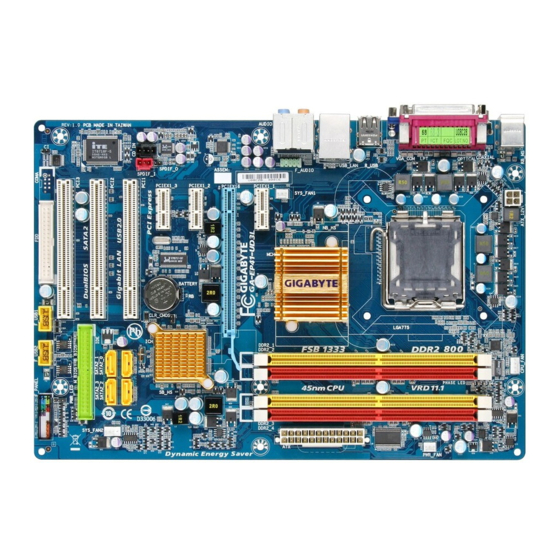
Page 7: Ga-Ep41-Ud3L/Us3L Motherboard Layout
GA-EP41-UD3L/ PCIEX1_1 GA-EP41-US3L PCIEX16 RTL8111C/D(L) PCIEX1_2 CLR_CMOS Intel ® ICH7 CODEC PCIEX1_3 SPDIF_O BATTERY CD_IN PCI1 SATA2_0 SATA2_2 SYS_FAN2 SPDIF_I PCI2 SATA2_1 SATA2_3 PCI3 B_BIOS M_BIOS PWR_LED F_USB1 F_USB2 F_PANEL «*» The GA-EP41-UD3L adopts All-Solid Capacitor design. — 7 -…
-
Page 8: Block Diagram
Block Diagram PCIe CLK CPU CLK+/- (100 MHz) LGA775 (333/266/200 MHz) Processor 1 PCI Express x16 Host Interface DDR2 800/667 MHz PCI Express x16 Dual Channel Memory ® Intel GMCH CLK (333/266/200 MHz) RJ45 RTL8111C/D(L) Dual BIOS ATA-100/66/33 PCI Express Bus IDE Channel 3 PCI Express x1 4 SATA 3Gb/s…
-
Page 9: Chapter 1 Hardware Installation
Chapter 1 Hardware Installation Installation Precautions The motherboard contains numerous delicate electronic circuits and components which can become damaged as a result of electrostatic discharge (ESD). Prior to installation, carefully read the user’s manual and follow these procedures: • Prior to installation, do not remove or break motherboard S/N (Serial Number) sticker or warranty sticker provided by your dealer.
-
Page 10: Product Specifications
Pentium processor/Intel Celeron processor in the LGA775 package ® ® ® ® (Go to GIGABYTE’s website for the latest CPU support list.) L2 cache varies with CPU Front Side Bus 1333/1066/800 MHz FSB Chipset North Bridge: Intel G41 Express Chipset ®…
-
Page 11
Internal Connectors 1 x 24-pin ATX main power connector 1 x 4-pin ATX 12V power connector 1 x floppy disk drive connector 1 x IDE connector 4 x SATA 3Gb/s connectors 1 x CPU fan header … -
Page 12
DDR2_1 or DDR2_3 socket; to install two memory modules, we suggest that you install them on the DDR2_1 and DDR2_3 sockets. (Go to GIGABYTE’s website for the latest memory support list.) (Note 3) Whether the CPU/system fan speed control function is supported will depend on the CPU/system cooler you install. -
Page 13: Installing The Cpu And Cpu Cooler
Read the following guidelines before you begin to install the CPU: • Make sure that the motherboard supports the CPU. (Go to GIGABYTE’s website for the latest CPU support list.) • Always turn off the computer and unplug the power cord from the power outlet before installing the CPU to prevent hardware damage.
-
Page 14
B. Follow the steps below to correctly install the CPU into the motherboard CPU socket. Before installing the CPU, make sure to turn off the computer and unplug the power cord from the power outlet to prevent damage to the CPU. CPU Socket Lever Step 1: Step 2:… -
Page 15: Installing The Cpu Cooler
1-3-2 Installing the CPU Cooler Follow the steps below to correctly install the CPU cooler on the motherboard. (The following procedure uses Intel boxed cooler as the example cooler.) ® Male Push Direction of the Arrow Sign on the Male Push The Top of Female Push Pin…
-
Page 16: Installing The Memory
DDR2_1 or DDR2_3 socket; to install two memory modules, we suggest that you install them on the DDR2_1 and DDR2_3 sockets. (Go to GIGABYTE’s website for the latest memory support list.) When memory modules of different capacity and chips are installed, a message which says mem- ory is operating in Flex Memory Mode will appear during the POST.
-
Page 17: Installing A Memory
1-4-2 Installing a Memory Before installing a memory module, make sure to turn off the computer and unplug the power cord from the power outlet to prevent damage to the memory module. DDR2 DIMMs are not compatible to DDR DIMMs. Be sure to install DDR2 DIMMs on this moth- erboard.
-
Page 18: Installing An Expansion Card
Installing an Expansion Card Read the following guidelines before you begin to install an expansion card: • Make sure the motherboard supports the expansion card. Carefully read the manual that came with your expansion card. • Always turn off the computer and unplug the power cord from the power outlet before installing an expansion card to prevent hardware damage.
-
Page 19: Back Panel Connectors
Back Panel Connectors PS/2 Keyboard and PS/2 Mouse Port Use the upper port (green) to connect a PS/2 mouse and the lower port (purple) to connect a PS/2 keyboard. Parallel Port Use the parallel port to connect devices such as a printer, scanner and etc. The parallel port is also called a printer port.
-
Page 20
Center/Subwoofer Speaker Out Jack (Orange) Use this audio jack to connect center/subwoofer speakers in a 5.1/7.1-channel audio configuration. Rear Speaker Out Jack (Black) Use this audio jack to connect rear speakers in a 4/5.1/7.1-channel audio configuration. Side Speaker Out Jack (Gray) Use this audio jack to connect side speakers in a 7.1-channel audio configuration. -
Page 21: Internal Connectors
Internal Connectors 3 19 ATX_12V F_PANEL F_AUDIO CPU_FAN CD_IN SYS_FAN1/2 SPDIF_I PWR_FAN SPDIF_O F_USB1/F_USB2 SATA2_0/1/2/3 CLR_CMOS PWR_LED PHASE_LED BATTERY Read the following guidelines before connecting external devices: • First make sure your devices are compliant with the connectors you wish to connect. • Before installing the devices, be sure to turn off the devices and your computer.
-
Page 22
1/2) ATX_12V/ATX (2×2 12V Power Connector and 2×12 Main Power Connector) With the use of the power connector, the power supply can supply enough stable power to all the components on the motherboard. Before connecting the power connector, first make sure the power supply is turned off and all devices are properly installed. -
Page 23
3/4/5) CPU_FAN/SYS_FAN1/SYS_FAN2/PWR_FAN (Fan Headers) The motherboard has a 4-pin CPU fan header (CPU_FAN), a 4-pin (SYS_FAN2) and a 3-pin (SYS_FAN1) system fan headers, and a 3-pin power fan header (PWR_FAN). Most fan headers possess a foolproof insertion design. When connecting a fan cable, be sure to connect it in the correct orientation (the black connector wire is the ground wire). -
Page 24
7) IDE (IDE Connector) The IDE connector supports up to two IDE devices such as hard drives and optical drives. Before attach- ing the IDE cable, locate the foolproof groove on the connector. If you wish to connect two IDE devices, remember to set the jumpers and the cabling according to the role of the IDE devices (for example, master or slave). -
Page 25: System Power Led Header
9) PWR_LED (System Power LED Header) This header can be used to connect a system power LED on the chassis to indicate system power status. The LED is on when the system is operating. The LED keeps blinking when the system is in S1 sleep state.
-
Page 26: F_Panel
11) F_PANEL (Front Panel Header) Connect the power switch, reset switch, speaker and system status indicator on the chassis front panel to this header according to the pin assignments below. Note the positive and negative pins before con- necting the cables. Message/Power/ Power Speaker…
-
Page 27: Cd In Connector
12) F_AUDIO (Front Panel Audio Header) The front panel audio header supports Intel High Definition audio (HD) and AC’97 audio. You may connect your chassis front panel audio module to this header. Make sure the wire assignments of the module con- nector match the pin assignments of the motherboard header.
-
Page 28
14) SPDIF_I (S/PDIF In Header, Red) This header supports digital S/PDIF In and can connect to an audio device that supports digital audio out via an optional S/PDIF In cable. For purchasing the optional S/PDIF In cable, please contact the local dealer. -
Page 29
16) F_USB1/F_USB2 (USB Headers) The headers conform to USB 2.0/1.1 specification. Each USB header can provide two USB ports via an optional USB bracket. For purchasing the optional USB bracket, please contact the local dealer. Pin No. Definition Power (5V) Power (5V) USB DX- USB DY-… -
Page 30: Clear Cmos Jumper
18) CLR_CMOS (Clearing CMOS Jumper) Use this jumper to clear the CMOS values (e.g. date information and BIOS configurations) and reset the CMOS values to factory defaults. To clear the CMOS values, place a jumper cap on the two pins to temporarily short the two pins or use a metal object like a screwdriver to touch the two pins for a few seconds.
-
Page 31: Chapter 2 Bios Setup
To see more advanced BIOS Setup menu options, you can press <Ctrl> + <F1> in the main menu of the BIOS Setup program. To upgrade the BIOS, use either the GIGABYTE Q-Flash or @BIOS utility. Q-Flash allows the user to quickly and easily upgrade or back up BIOS without entering the operating •…
-
Page 32: Startup Screen
Startup Screen The following screens may appear when the computer boots. A. The LOGO Screen (Default) Function Keys B. The POST Screen Award Modular BIOS v6.00PG, An Energy Star Ally Copyright (C) 1984-2009, Award Software, Inc. EP41-UD3L F2e Motherboard Model BIOS Version Function Keys <DEL>: BIOS Setup <F9>: XpressRecovery2 <F12>: Boot Menu <End>: Qflash…
-
Page 33: The Main Menu
Once you enter the BIOS Setup program, the Main Menu (as shown below) appears on the screen. Use ar- row keys to move among the items and press <Enter> to accept or enter a sub-menu. (Sample BIOS Version: GA-EP41-UD3L F2e) CMOS Setup Utility-Copyright (C) 1984-2009 Award Software MB Intelligent Tweaker(M.I.T.)
-
Page 34: Standard Cmos Features
The Functions of the <F11> and <F12> keys (For the Main Menu Only) F11: Save CMOS to BIOS This function allows you to save the current BIOS settings to a profile. You can create up to 8 profiles (Profile 1-8) and name each profile.
-
Page 35: Mb Intelligent Tweaker(M.i.t.)
MB Intelligent Tweaker(M.I.T.) CMOS Setup Utility-Copyright (C) 1984-2009 Award Software MB Intelligent Tweaker(M.I.T.) Item Help Robust Graphics Booster [Auto] Menu Level CPU Clock Ratio [10X] (Note) Fine CPU Clock Ratio [+0.0] (Note) CPU Frequency 2.66GHz ( 266×10) ******** Clock Chip Control ******** >>>>>…
-
Page 36: Cpu Frequency
Robust Graphics Booster Robust Graphics Booster (R.G.B.) helps to enhance the performance of the graphics chip and memory. Auto allows the BIOS to automatically set the R.G.B. mode based on system configurations. Options are: Auto (default), Fast, Turbo. CPU Clock Ratio (Note) Allows you to alter the clock ratio for the installed CPU.
-
Page 37
(G)MCH Frequency Latch Allows you to fix the chipset frequency at system bootup. Options for adjusting memory multiplier below may differ according to the fixed frequency. Options are: Auto (default), 200MHz, 266MHz, 333MHz. System Memory Multiplier (SPD) Allows you to set the system memory multiplier. Options are dependent on CPU FSB and the (G)MCH Frequency Latch settings. -
Page 38
>>>>> Advanced Timing Control tRRD Options are: Auto (default), 1~15. tWTR Options are: Auto (default), 1~31. Options are: Auto (default), 1~31. tRFC Options are: Auto (default), 1~255. tRTP Options are: Auto (default), 1~15. Command Rate(CMD) Options are: Auto (default), 1~3. >>>>>… -
Page 39
Trd2rd(Different Rank) Options are: Auto (default), 1~15. Twr2wr(Different Rank) Options are: Auto (default), 1~15. Twr2rd(Different Rank) Options are: Auto (default), 1~15. Trd2wr(Same/Diff Rank) Options are: Auto (default), 1~15. DIMM1 Clock Skew Control Options are: Auto (default), +800ps~-700ps. DIMM2 Clock Skew Control Options are: Auto (default), +800ps~-700ps. -
Page 40
Clk Driving Pull-Up Level Options are: Auto (default), +8~-7. Data Driving Pull-Down Level Options are: Auto (default), +8~-7. Cmd Driving Pull-Down Level Options are: Auto (default), +8~-7. Ctrl Driving Pull-Down Level Options are: Auto (default), +8~-7. Clk Driving Pull-Down Level Options are: Auto (default), +8~-7. -
Page 41: Standard Cmos Features
Standard CMOS Features CMOS Setup Utility-Copyright (C) 1984-2009 Award Software Standard CMOS Features Item Help Date (mm:dd:yy) Tue, Jan 20 2009 Menu Level Time (hh:mm:ss) 22:31:24 IDE Channel 0 Master [None] IDE Channel 0 Slave [None] IDE Channel 2 Master [None] …
-
Page 42
The following fields display your hard drive specifications. If you wish to enter the parameters manually, refer to the information on the hard drive. Capacity Approximate capacity of the currently installed hard drive. Cylinder Number of cylinders. Head Number of heads. Precomp Write precompensation cylinder. -
Page 43: Advanced Bios Features
Advanced BIOS Features CMOS Setup Utility-Copyright (C) 1984-2009 Award Software Advanced BIOS Features Item Help Hard Disk Boot Priority [Press Enter] Menu Level First Boot Device [Floppy] Second Boot Device [Hard Disk] Third Boot Device [CDROM] Password Check [Setup] HDD S.M.A.R.T.
-
Page 44
CPU Multi-Threading (Note) Allows you to determine whether to enable all CPU cores and multi-threading function when using an Intel CPU that supports multi-core technology. This feature only works for operating systems that support multi-processor mode. Enabled Enables all CPU cores and multi-threading capability. (Default) Disabled Enables only one CPU core. -
Page 45: Init Display First
Full Screen LOGO Show Allows you to determine whether to display the GIGABYTE Logo at system startup. Disabled displays normal POST message. (Default: Enabled) Init Display First Specifies the first initiation of the monitor display from the installed PCI graphics card or the PCI Express graphics card.
-
Page 46: Integrated Peripherals
Integrated Peripherals CMOS Setup Utility-Copyright (C) 1984-2009 Award Software Integrated Peripherals Item Help On-Chip Primary PCI IDE [Enabled] Menu Level On-Chip SATA Mode [Auto] x PATA IDE Set to Ch.0 Master/Slave SATA Port 0/2 Set to Ch.2 Master/Slave SATA Port 1/3 Set to Ch.3 Master/Slave Azalia Codec [Auto]…
-
Page 47
SATA Port 1/3 Set to This value is dependent on the On-Chip SATA Mode and PATA IDE Set to settings. When PATA IDE Set to is configured to Ch. 0 Master/Slave, this option will be automatically set to Ch. 1 Master/Slave. -
Page 48: Onboard Parallel Port
When a Cable Problem Occurs… If a cable problem occurs on a specified pair of wires, the Status field will show Short and then length shown will be the approximate distance to the fault or short. Example: Part1-2 Status = Short / Length Explanation: A fault or short might occur at about 2m on Part 1-2.
-
Page 49: Power Management Setup
Power Management Setup CMOS Setup Utility-Copyright (C) 1984-2009 Award Software Power Management Setup Item Help ACPI Suspend Type [S3(STR)] Menu Level Soft-Off by PWR-BTTN [Instant-Off] PME Event Wake Up [Enabled] Power On by Ring [Enabled] Resume by Alarm [Disabled] Date (of Month) Alarm Everyday Time (hh:mm:ss) Alarm…
-
Page 50
Resume by Alarm Determines whether to power on the system at a desired time. (Default: Disabled) If enabled, set the date and time as following: Date (of Month) Alarm: Turn on the system at a specific time on each day or on a specific day in a month. -
Page 51: Pnp/Pci Configurations
PnP/PCI Configurations CMOS Setup Utility-Copyright (C) 1984-2009 Award Software PnP/PCI Configurations Item Help PCI1 IRQ Assignment [Auto] Menu Level PCI2 IRQ Assignment [Auto] PCI3 IRQ Assignment [Auto] higf : Move Enter: Select +/-/PU/PD: Value F10: Save ESC: Exit F1: General Help F5: Previous Values F6: Fail-Safe Defaults F7: Optimized Defaults…
-
Page 52: Pc Health Status
PC Health Status CMOS Setup Utility-Copyright (C) 1984-2009 Award Software PC Health Status Item Help Reset Case Open Status [Disabled] Menu Level Case Opened Vcore 1.140V DDR18V 1.840V +3.3V 3.328V +12V 12.048V Current System Temperature Current CPU Temperature Current CPU FAN Speed 2872 RPM Current SYSTEM FAN2 Speed Current POWER FAN Speed…
-
Page 53: Load Fail-Safe Defaults
2-10 Load Fail-Safe Defaults CMOS Setup Utility-Copyright (C) 1984-2009 Award Software MB Intelligent Tweaker(M.I.T.) Load Fail-Safe Defaults Standard CMOS Features Load Optimized Defaults Advanced BIOS Features Set Supervisor Password Integrated Peripherals Set User Password Power Management Setup Save &…
-
Page 54: Set Supervisor/User Password
2-12 Set Supervisor/User Password CMOS Setup Utility-Copyright (C) 1984-2009 Award Software MB Intelligent Tweaker(M.I.T.) Load Fail-Safe Defaults Standard CMOS Features Load Optimized Defaults Advanced BIOS Features Set Supervisor Password Integrated Peripherals Set User Password Power Management Setup Save &…
-
Page 55: Save & Exit Setup
2-13 Save & Exit Setup CMOS Setup Utility-Copyright (C) 1984-2009 Award Software MB Intelligent Tweaker(M.I.T.) Load Fail-Safe Defaults Standard CMOS Features Load Optimized Defaults Advanced BIOS Features Set Supervisor Password Save to CMOS and EXIT (Y/N)? Y Integrated Peripherals Set User Password …
-
Page 56
BIOS Setup — 56 -… -
Page 57: Chapter 3 Drivers Installation
Chapter 3 Drivers Installation • Before installing the drivers, first install the operating system. • After installing the operating system, insert the motherboard driver disk into your optical drive. The driver Autorun screen is automatically displayed which looks like that shown in the screen shot below.
-
Page 58: Application Software
Application Software This page displays all the utilities and applications that GIGABYTE develops and some free software. You can click the Install button on the right of an item to install it. Technical Manuals This page provides GIGABYTE’s application guides, content descriptions for this driver disk, and the mother- board manuals.
-
Page 59: Contact
Contact For the detailed contact information of the GIGABYTE Taiwan headquarter or worldwide branch offices, click the URL on this page to link to the GIGABYTE website. System This page provides the basic system information. — 59 — Drivers Installation…
-
Page 60: Download Center
Download Center To update the BIOS, drivers, or applications, click the Download Center button to link to the GIGABYTE website. The latest version of the BIOS, drivers, or applications will be displayed. Drivers Installation — 60 -…
-
Page 61: Chapter 4 Unique Features
Chapter 4 Unique Features Xpress Recovery2 Xpress Recovery2 is a utility that allows you to quickly compress and back up your system data and perform restoration of it. Supporting NTFS, FAT32, and FAT16 file systems, Xpress Recovery2 can back up data on PATA and SATA hard drives and restore it.
-
Page 62
Step 3: Step 4: When partitioning your hard drive, make sure to After the operating system is installed, right-click the Computer icon on your desktop and select leave unallocated space (10 GB or more is recom- mended; actual size requirements vary, depending Manage. -
Page 63
D. Using the Restore Function in Xpress Recovery2 Select RESTORE to restore the backup to your hard drive in case the system breaks down. The RESTORE option will not be present if no backup is created before. E. Removing the Backup Step 1: Step 2: If you wish to remove the backup file, select… -
Page 64: Bios Update Utilities
4-2-1 Updating the BIOS with the Q-Flash Utility A. Before You Begin From GIGABYTE’s website, download the latest compressed BIOS update file that matches your moth- erboard model. Extract the file and save the new BIOS file (e.g. EP41UD3L.F1) to your floppy disk, USB flash drive, or hard drive.
-
Page 65
B. Updating the BIOS When updating the BIOS, choose the location where the BIOS file is saved. The following procedure as- sumes that you save the BIOS file to a floppy disk. Step 1: Insert the floppy disk containing the BIOS file into the floppy disk drive. In the main menu of Q-Flash, use the up or down arrow key to select Update BIOS from Drive and press <Enter>. -
Page 66
Step 4: Press <Esc> and then <Enter> to exit Q-Flash and reboot the system. As the system boots, you should see the new BIOS version is present on the POST screen. Step 5: During the POST, press <Delete> to enter BIOS Setup. Select Load Optimized Defaults and press <Enter> to load BIOS defaults. -
Page 67: Updating The Bios With The @Bios Utility
BIOS or a system that is unable to start. Do not use the G.O.M. (GIGABYTE Online Management) function when using @BIOS. GIGABYTE product warranty does not cover any BIOS damage or system failure resulting from an inad- equate BIOS flashing.
-
Page 68: Easytune 6
EasyTune 6 GIGABYTE’s EasyTune 6 is a simple and easy-to-use interface that allows users to fine-tune their system settings or do overclock/overvoltage in Windows environment. The user-friendly EasyTune 6 interface also includes tabbed pages for CPU and memory information, letting users read their system-related information without the need to install additional software.
-
Page 69: Dynamic Energy Saver Advanced
The Dynamic Energy Saver Advanced Interface A. Meter Mode In Meter Mode, GIGABYTE Dynamic Energy Saver Advanced shows how much power they have saved in a set period of time. Meter Mode — Button Information Table…
-
Page 70
B. Total Mode In Total Mode, users are able to see how much total power savings they have accumulated in a set period of time since activating Dynamic Energy Saver Advanced for the first time (Note 4) Total Mode — Button Information Table Button Description Dynamic Energy Saver On/Off Switch (Default: Off) Motherboard Phase LED On/Off Switch (Default: On) -
Page 71: Q-Share
Q-Share, you are able to share your data with computers on the same network, making full use of Internet resources. Directions for using Q-Share After installing Q-Share from the motherboard driver disk, go to Start>All Programs>GIGABYTE>Q-Share.exe to launch the Q-Share tool. Find the Q-Share icon in your taskbar and right-click on this icon to configure the data sharing settings.
-
Page 72: Time Repair
Time Repair Based on the Microsoft Volume Shadow Copy Services technology, Time Repair allows you to quickly back up and restore your system data in the Windows Vista operating system. Time Repair supports NTFS file system and can restore system data on PATA and SATA hard drives. System Restore Choose a system restore point using the navigation bar on the right or at the bottom of the screen to view the system data backed up at different time.
-
Page 73: Chapter 5 Appendix
Chapter 5 Appendix Configuring Audio Input and Output 5-1-1 Configuring 2/4/5.1/7.1-Channel Audio The motherboard provides six audio jacks on the back panel which support 2/4/5.1/7.1-channel audio. (Note) The picture to the right shows the default audio jack Center/Subwoofer Line In Speaker Out assignments.
-
Page 74
Step 2: Connect an audio device to an audio jack. The The current connected device is dialog box appears. Select the device according to the type of device you connect. Then click OK. Step 3: On the Speakers screen, click the Speaker Configura- tion tab. -
Page 75: Configuring S/Pdif In/Out
5-1-2 Configuring S/PDIF In/Out A. S/PDIF In The S/PDIF In cable (optional) allows you to input digital audio signals to the computer for audio processing. S/PDIF In Cable Optical Coaxial S/PDIF In S/PDIF In 1. Installing the S/PDIF In Cable: Step 1: Step 2: First, attach the connector at the end of the cable…
-
Page 76
B. S/PDIF Out The S/PDIF Out jacks can transmit audio signals to an external decoder for decoding to get the best audio quality. 1. Connecting a S/PDIF Out Cable: S/PDIF Coaxial Cable S/PDIF Optical Cable Connect a S/PDIF coaxial cable or a S/PDIF optical cable (either one) to an external decoder for transmitting the S/PDIF digital audio signals. -
Page 77: Configuring Microphone Recording
5-1-3 Configuring Microphone Recording Step 1: After installing the audio driver, the HD Audio Manager icon will appear in the notification area. Double-click the icon to access the HD Audio Manager. Step 2: Connect your microphone to the Mic in jack (pink) on the back panel or the Mic in jack (pink) on the front panel.
-
Page 78
Step 4: To raise the recording and playback volume for the microphone, click the Microphone Boost icon the right of the Recording Volume slider and set the Microphone Boost level. Step 5: After completing the settings above, click Start, point to All Programs, point to Accessories, and then click Sound Recorder to begin the sound recording. -
Page 79: Using The Sound Recorder
Step 3: When the Stereo Mix item appears, right-click on this item and select Enable. Then set it as the default device. Step 4: Now you can access the HD Audio Manager to config- ure Stereo Mix and use Sound Recorder to record the sound.
-
Page 80: Troubleshooting
5-2-1 Frequently Asked Questions To read more FAQs for your motherboard, please go to the Support&Downloads\Motherboard\FAQ page on GIGABYTE’s website. Q: In the BIOS Setup program, why are some BIOS options missing? A: Some advanced options are hidden in the BIOS Setup program. Press <Delete> to enter BIOS Setup dur- ing the POST.
-
Page 81: Troubleshooting Procedure
5-2-2 Troubleshooting Procedure If you encounter any troubles during system startup, follow the troubleshooting procedure below to solve the problem. START Turn off the power. Remove all peripherals, connecting cables, and power cord etc. Make sure the motherboard does not short-circuit with the chassis or Isolate the short circuit.
-
Page 82
The power supply, CPU or When the computer is turned on, is the CPU cooler running? CPU socket might fail. The problem is verified and solved. The graphics card, expansion slot, or monitor Check if there is display on your monitor. might fail. -
Page 83: Regulatory Statements
Contravention will be prosecuted. We believe that the information contained herein was accurate in all respects at the time of printing. GIGABYTE cannot, however, assume any responsibility for errors or omissions in this text. Also note that the informa- tion in this document is subject to change without notice and should not be construed as a commitment by GIGABYTE.
-
Page 84
Finally, we suggest that you practice other environmentally friendly actions by understanding and using the energy-saving features of this product (where applicable), recycling the inner and outer packaging (including shipping containers) this product was delivered in, and by disposing of or recycling used batteries properly. With your help, we can reduce the amount of natural resources needed to produce electrical and electronic equipment, minimize the use of landfills for the disposal of «end of life»… -
Page 85
— 85 — Appendix… -
Page 86
Appendix — 86 -… -
Page 87
Shenyang http://rma.gigabyte-usa.com Web address: http://latam.giga-byte.com TEL: +86-24-83992901 • Giga-Byte SINGAPORE PTE. LTD. — Singapore FAX: +86-24-83992909 • GIGABYTE TECHNOLOGY (INDIA) LIMITED — India WEB address : http://www.gigabyte.sg • Thailand WEB address : http://www.gigabyte.in WEB address : http://th.giga-byte.com • Saudi Arabia •… -
Page 88
WEB address : http://www.giga-byte.gr WEB address : http://www.giga-byte.kz • Czech Republic You may go to the GIGABYTE website, select your language WEB address : http://www.gigabyte.cz in the language list on the top right corner of the website. • GIGABYTE Global Service System…
-
Драйверы
8
-
Инструкции по эксплуатации
8
Языки:

Gigabyte GA-EP41-UD3L инструкция по эксплуатации
(72 страницы)
- Языки:Венгерский, Греческий, Испанский, Итальянский, Немецкий, Польский, Португальский, Русский, Турецкий, Французский, Чешский
-
Тип:
PDF -
Размер:
18.6 MB -
Описание:
Installation Guidebook


На NoDevice можно скачать инструкцию по эксплуатации для Gigabyte GA-EP41-UD3L. Руководство пользователя необходимо для ознакомления с правилами установки и эксплуатации Gigabyte GA-EP41-UD3L. Инструкции по использованию помогут правильно настроить Gigabyte GA-EP41-UD3L, исправить ошибки и выявить неполадки.
Посмотреть инструкция для Gigabyte GA-EP41-UD3L бесплатно. Руководство относится к категории материнские платы, 1 человек(а) дали ему среднюю оценку 7.1. Руководство доступно на следующих языках: английский. У вас есть вопрос о Gigabyte GA-EP41-UD3L или вам нужна помощь? Задайте свой вопрос здесь
Не можете найти ответ на свой вопрос в руководстве? Вы можете найти ответ на свой вопрос ниже, в разделе часто задаваемых вопросов о Gigabyte GA-EP41-UD3L.
Какая ширина Gigabyte GA-EP41-UD3L?
Gigabyte GA-EP41-UD3L имеет ширину 305 mm.
Какая толщина Gigabyte GA-EP41-UD3L?
Gigabyte GA-EP41-UD3L имеет толщину 210 mm.
Инструкция Gigabyte GA-EP41-UD3L доступно в русский?
К сожалению, у нас нет руководства для Gigabyte GA-EP41-UD3L, доступного в русский. Это руководство доступно в английский.
Не нашли свой вопрос? Задайте свой вопрос здесь
(Ocr-Read Summary of Contents of some pages of the Gigabyte GA-EP41-UD3L Document (Main Content), UPD: 03 April 2023)
-
54, BIOS Setup — 54 — Press <Enter> on this item and type the password with up to 8 characters and then press <Enter>. You will be requested to conrm the password. Type the password again and press <Enter>. The BIOS Setup program allows you to specify two separate passwords: Supervisor Password When a system password is set and the Password Check item in Advanced BIOS Features is set to Setup, you must enter the supervisor password f…
-
26, Hardware Installation — 26 — 11) F_PANEL (Front Panel Header) Connect the power switch, reset switch, speaker and system status indicator on the chassis front panel to this header according to the pin assignments below. Note the positive and negative pins before con- necting the cables. • PW (Power Switch, Red): Connects to the power switch on the chassis front panel. You may congure the way to turn off your system using the power switch (refer t…
-
76, Appendix — 76 — B. S/PDIF Out The S/PDIF Out jacks can transmit audio signals to an external decoder for decoding to get the best audio quality. 1. Connecting a S/PDIF Out Cable: 2. Conguring S/PDIF Out: On the Digital Output screen, click the Default Format tab and then select the sample rate and bit depth. Click OK to complete. S/PDIF Coaxial Cable Connect a S/PDIF coaxial cable or a S/PDIF optical cable (either one) to an external decoder for transmitting the S/PDIF digital aud…
-
37, — 37 — BIOS Setup (G)MCH Frequency Latch Allows you to x the chipset frequency at system bootup. Options for adjusting memory multiplier below may differ according to the xed frequency. Options are: Auto (default), 200MHz, 266MHz, 333MHz. System Memory Multiplier (SPD) Allows you to set the system memory multiplier. Options are dependent on CPU FSB and the (G)MCH Frequency Latch settings. Auto sets memory multiplier according to memory SPD data. (Default: Auto)…
-
16, Hardware Installation — 16 — 1-4-1 Dual Channel Memory Conguration This motherboard provides four DDR2 memory sockets and supports Dual Channel Tech- nology. After the memory is installed, the BIOS will automatically detect the specications and capacity of the memory. Enabling Dual Channel memory mode will double the original memory bandwidth. The four DDR2 memory sockets are divided into two channels and each channel has two memory sockets as…
-
81, — 81 — Appendix 5-2-2 Troubleshooting Procedure If you encounter any troubles during system startup, follow the troubleshooting procedure below to solve the problem. START A Turn off the power. Remove all peripherals, connecting cables, and power cord etc. Isolate the short circuit. Secure the CPU cooler on the CPU. Connect the CPU cooler power cable to the motherboard. Correctly insert the memory into the memory socket. (Continued…) Yes The problem is veried and solved. The p…
-
44, Gigabyte GA-EP41-UD3L BIOS Setup — 44 — CPU Multi-Threading (Note) Allows you to determine whether to enable all CPU cores and multi-threading function when using an Intel CPU that supports multi-core technology. This feature only works for operating systems that support multi-processor mode. Enabled Enables all CPU cores and multi-threading capability. (Default) Disabled Enables only one CPU core. Limit CPUID Max. to 3 (…
-
68, Unique Features — 68 — 4-3 EasyTune 6 GIGABYTE’s EasyTune 6 is a simple and easy-to-use interface that allows users to ne-tune their system settings or do overclock/overvoltage in Windows environment. The user-friendly EasyTune 6 interface also includes tabbed pages for CPU and memory information, letting users read their system-related information without the need to install additional software. The EasyTune 6 Interfac…
-
71, — 71 — Unique Features 4-5 Q-Share Q-Share is an easy and convenient data sharing tool. After conguring your LAN connection settings and Q-Share, you are able to share your data with computers on the same network, making full use of Internet resources. Directions for using Q-Share After installing Q-Share from the motherboard driver disk, go to Start>All Programs>GIGABYTE>Q-Share.exe to launch the…
-
73, — 73 — Appendix 5-1-1 Conguring 2/4/5.1/7.1-Channel Audio The motherboard provides six audio jacks on the back panel which support 2/4/5.1/7.1-channel (Note) audio. The picture to the right shows the default audio jack assignments. The integrated HD (High Definition) audio provides jack retasking capability that allows the user to change the function for each jack through the audio driver. For example, in a 4-channel audio congu…
-
17, — 17 — Hardware Installation 1-4-2 Installing a Memory Notch DDR2 DIMM A DDR2 memory module has a notch, so it can only t in one direction. Follow the steps below to correctly install your memory modules in the memory sockets. Step 1: Note the orientation of the memory module. Spread the retaining clips at both ends of the memory socket. Place the memory module on the socket. As indicated in the picture on the left, place your n- gers on the t…
-
24, Hardware Installation — 24 — 7) IDE (IDE Connector) The IDE connector supports up to two IDE devices such as hard drives and optical drives. Before attach- ing the IDE cable, locate the foolproof groove on the connector. If you wish to connect two IDE devices, remember to set the jumpers and the cabling according to the role of the IDE devices (for example, master or slave). (For information about conguring master/slave settings for the IDE devices, read the instructions …
-
36, Gigabyte GA-EP41-UD3L BIOS Setup — 36 — Robust Graphics Booster Robust Graphics Booster (R.G.B.) helps to enhance the performance of the graphics chip and memory. Auto allows the BIOS to automatically set the R.G.B. mode based on system congurations. Options are: Auto (default), Fast, Turbo. CPU Clock Ratio (Note) Allows you to alter the clock ratio for the installed CPU. The item is present only if a CPU with unlocked clock ratio is installed…
-
38, Gigabyte GA-EP41-UD3L BIOS Setup — 38 — >>>>> Advanced Timing Control tRRD Options are: Auto (default), 1~15. tWTR Options are: Auto (default), 1~31. tWR Options are: Auto (default), 1~31. tRFC Options are: Auto (default), 1~255. tRTP Options are: Auto (default), 1~15. Command Rate(CMD) Options are: Auto (default), 1~3. >>>>> Channel A/B Channel A/B Timing Settings CMOS Setup Utility-Copyright (C) 1984-2009 Award Software Channel A/B T…
-
23, — 23 — Hardware Installation 3/4/5) CPU_FAN/SYS_FAN1/SYS_FAN2/PWR_FAN (Fan Headers) The motherboard has a 4-pin CPU fan header (CPU_FAN), a 4-pin (SYS_FAN2) and a 3-pin (SYS_FAN1) system fan headers, and a 3-pin power fan header (PWR_FAN). Most fan headers possess a foolproof insertion design. When connecting a fan cable, be sure to connect it in the correct orientation (the black connector wire is the ground wire). The motherboard supports CPU fan speed control…
-
8, — 8 — Block Diagram PS/2 KB/Mouse 8 USB Ports LGA775 Processor Host Interface Intel ® G41 GMCH CLK (333/266/200 MHz) DDR2 800/667 MHz Intel ® ICH7 3 PCI PCI Bus Dual Channel Memory PCI CLK (33 MHz) PCIe CLK (100 MHz) PCI Express x16 IT8718 Floppy LPT Port CPU CLK+/- (333/266/200 MHz) 3 PCI Express x1 PCI Express Bus PCIe CLK (100 MHz) x1 x1 x1 x1 4 SATA 3Gb/s ATA-100/66/33 IDE Channel 1 PCI Express x1…
- Производитель
- Gigabyte
- Модель
- GA-EP41-UD3L
- Операционная система
-
- Неизвестная ОС
- Тип файла
-
- Инструкция
- Версия
-
1201
32-bit
Просмотреть содержимое архива
Вы нашли то, что искали?
Дополнительная информация
Vietnamese
Полезно
0 %
0
Commentary
Ваше имя