-
Page 3
___________________ Introduction ___________________ Description ___________________ SENTRON Applications ___________________ Accessories Protection devices 3VA molded case circuit breakers ___________________ with IEC certificate Service and maintenance ___________________ Technical specifications Manual ___________________ Appendix ___________________ ESD guidelines ___________________ List of abbreviations ___________________ Conversion tables 03/2019 A5E03603177010-03… -
Page 4
Note the following: WARNING Siemens products may only be used for the applications described in the catalog and in the relevant technical documentation. If products and components from other manufacturers are used, these must be recommended or approved by Siemens. Proper transport, storage, installation, assembly, commissioning, operation and maintenance are required to ensure that the products operate safely and without any problems. -
Page 5: Table Of Contents
Table of contents Introduction……………………… 9 About this documentation ………………..9 Product-specific information………………..10 1.2.1 Target readers ……………………10 1.2.2 Technical Support ………………….10 1.2.3 Reference documents ………………….. 10 Description ……………………..13 Overview — applications and portfolio …………….. 13 2.1.1 Applications and possible uses ………………14 2.1.2 Portfolio ……………………..
-
Page 6
Table of contents 2.6.4 Overload protection (L) …………………..75 2.6.5 Short-time delayed short-circuit protection (S) …………..76 2.6.6 Instantaneous short-circuit protection (I) …………….76 2.6.7 Ground-fault protection (G) ………………..76 2.6.8 Neutral conductor protection (N) ………………79 2.6.9 Zone selective interlocking (ZSI) ………………82 Thermal-magnetic trip unit ………………..85 2.7.1 Thermal trip unit (L) ………………….85 2.7.2… -
Page 7
Table of contents Safety-related applications of 3VA molded case circuit breakers ……..183 Accessories ……………………..185 Overview of accessories for 3VA molded case circuit breakers ……..185 4.1.1 Accessories groups ………………….185 4.1.2 Possible combinations of of accessories …………….186 Internal accessories…………………. -
Page 8
Table of contents Motor operators ……………………331 4.6.1 MO310 side mounted motor operator …………….331 4.6.1.1 MANUAL, AUTO and LOCK modes ………………334 4.6.1.2 Closing, opening and resetting the 3VA molded case circuit breaker ………336 4.6.1.3 Faults, causes of faults and rectification of faults …………..338 4.6.2 Motor operator MO320 …………………339 4.6.2.1… -
Page 9
Table of contents 4.10 EFB300 external function box ………………495 4.10.1 General information ………………….495 4.10.2 Power supply……………………496 4.10.3 Functions of the digital input and digital outputs …………… 496 4.10.4 Zone selective interlocking (ZSI) ………………499 4.10.5 <SET> button ……………………501 4.10.6 Technical specifications ……………….. -
Page 10
Table of contents 6.2.1.3 3VA13 / 3VA14…………………….568 6.2.1.4 3VA20 / 3VA21 / 3VA22 ………………..569 6.2.1.5 3VA23 / 3VA24…………………….570 6.2.1.6 3VA25 ……………………..571 6.2.2 Dimensions of accessories ………………..572 6.2.2.1 Connection technology …………………572 6.2.2.2 Plug-in and draw-out units ………………..584 6.2.2.3 Manual operators ………………….587 6.2.2.4 Motor operators ……………………600 6.2.2.5… -
Page 11: Introduction
Introduction About this documentation 3VA molded case circuit breakers with certification according to standard IEC 60947 The 3VA molded case circuit breakers from the portfolio of SENTRON protection, switching, measuring and monitoring devices ensure the reliable protection of people and property as integral components of efficient power distribution systems.
-
Page 12: Product-Specific Information
● Cubicle manufacturers ● Switchgear manufacturers ● Maintenance personnel 1.2.2 Technical Support You can find further support on the Internet at: Technical Support (http://www.siemens.com/lowvoltage/technical-support) 1.2.3 Reference documents Further documents You will find further information in the following documents: Table 1- 1…
-
Page 13
Distribution in Low-Voltage Net- works), substantially extended and revised edition 1997 Siemens: Residual Current Protective E10003-E38-9T-B3011 — Devices, Low-Voltage Circuit Protection Technology Primer Siemens AG © 04 / 2009 3VA molded case circuit breakers with IEC certificate Manual, 03/2019, A5E03603177010-03… -
Page 14
Introduction 1.2 Product-specific information 3VA molded case circuit breakers with IEC certificate Manual, 03/2019, A5E03603177010-03… -
Page 15: Description
Description Overview — applications and portfolio This chapter provides an overview of all molded case circuit breakers in the 3VA portfolio and describes the potential areas of application for different circuit breaker models. The topics discussed in this chapter are listed below: ●…
-
Page 16: Applications And Possible Uses
Description 2.1 Overview — applications and portfolio 2.1.1 Applications and possible uses The two tables below show examples of possible uses and applications for 3VA molded case circuit breakers. Possible uses The 3VA molded case circuit breakers can be used in various areas where they perform different protection tasks.
-
Page 17
Description 2.1 Overview — applications and portfolio Functions and applications 3VA molded case circuit breakers are used for various functions as shown in the table below: Molded case circuit breakers are primarily designed for the following applications: ● Subdistribution systems ●… -
Page 18: Portfolio
Description 2.1 Overview — applications and portfolio 2.1.2 Portfolio The 3VA molded case circuit breakers set new standards in flexibility and the variety of modular accessories available. Standardized accessories suitable for use with several sizes of the 3VA molded case circuit breaker up to 1000 A together with quick and easy installation help to cut costs and save time.
-
Page 19
Description 2.1 Overview — applications and portfolio 3VA1 molded case circuit breakers The 3VA1 molded case circuit breakers reliably perform all the tasks required for line protection. Features The key features of the 3VA1 range are: ● Compact design ● 1 and 2-pole versions in size 160 A; 3 and 4-pole versions in sizes 100 A, 160 A, 250 A, 400 A and 630 A ●… -
Page 20
Description 2.1 Overview — applications and portfolio 3VA2 molded case circuit breakers The 3VA2 molded case circuit breakers reliably perform all the tasks associated with line and generator protection. This range is designed for applications with more exacting requirements: ● Increased breaking capacity ●… -
Page 21
Description 2.1 Overview — applications and portfolio Selective contact system With its contact system, the 3VA2 molded case circuit breaker is designed for fast selectivity tripping. The selective contact system ensures the following: ● Dynamic instantaneous short-circuit range ● High breaking capacity ●… -
Page 22: Application Examples
Description 2.1 Overview — applications and portfolio 2.1.3 Application examples 3VA molded case circuit breakers with IEC certificate Manual, 03/2019, A5E03603177010-03…
-
Page 23
Description 2.1 Overview — applications and portfolio 3VA molded case circuit breakers with IEC certificate Manual, 03/2019, A5E03603177010-03… -
Page 24: Detailed Information About Applications And Possible Uses
Description 2.1 Overview — applications and portfolio 2.1.4 Detailed information about applications and possible uses 3VA molded case circuit breakers with IEC certificate Manual, 03/2019, A5E03603177010-03…
-
Page 25
Description 2.1 Overview — applications and portfolio See also Applications (Page 109) 3VA molded case circuit breakers with IEC certificate Manual, 03/2019, A5E03603177010-03… -
Page 26: Technical Specifications
Description 2.1 Overview — applications and portfolio 2.1.5 Technical specifications A side plate must be installed (see chapter Insulating measures (Page 246)) if the installation conditions on the right-hand side are such that the device is not finger-safe. 125 A, 160 A: I = 36 kA / 36 kA 3VA molded case circuit breakers with IEC certificate Manual, 03/2019, A5E03603177010-03…
-
Page 27
Description 2.1 Overview — applications and portfolio a. A. On request 3VA molded case circuit breakers with IEC certificate Manual, 03/2019, A5E03603177010-03… -
Page 28
Description 2.1 Overview — applications and portfolio 3VA molded case circuit breakers with IEC certificate Manual, 03/2019, A5E03603177010-03… -
Page 29
Description 2.1 Overview — applications and portfolio a. A. On request Utilization category B only for 400 A and 500 A and ETUs 5-series 8-series 400/500 A and I 630 A: I = 65 kA 3VA molded case circuit breakers with IEC certificate Manual, 03/2019, A5E03603177010-03… -
Page 30: Molded Case Circuit Breakers And Accessories In The System
Description 2.1 Overview — applications and portfolio 2.1.6 Molded case circuit breakers and accessories in the system The 3VA molded case circuit breakers come with a large portfolio of internal and external accessories that can be installed flexibly in any size of circuit breaker (depending on the type of accessory).
-
Page 31
Description 2.1 Overview — applications and portfolio Overview of accessories in the system 3VA molded case circuit breakers with IEC certificate Manual, 03/2019, A5E03603177010-03… -
Page 32: Ergonomic Design
Description 2.2 Ergonomic design Ergonomic design This chapter provides an overview of the ergonomic design features of the 3VA molded case circuit breakers and explains what makes them so special. The topics discussed in this chapter are listed below: ● Optional installation variants ●…
-
Page 33: The Right Circuit Breaker For Any Installation Conditions
Description 2.2 Ergonomic design 2.2.1 The right circuit breaker for any installation conditions The range of molded case circuit breakers can be equipped with additional components so that they can be installed as fully functional switches in any location, a feature of the product which affords maximum flexibility to system planners.
-
Page 34
Description 2.2 Ergonomic design Optional installation variants 3VA molded case circuit breakers are available in the following installation variants: ① ● Fixed mounted ② ● Plug-in technology ③ ● Draw-out technology All variants offer the full range of functions, e.g. they can be equipped with every kind of accessory. -
Page 35
Description 2.2 Ergonomic design Indication of switching positions in the draw-out unit The picture below illustrates the colors used to indicate the switching position in the draw-out unit: The switching position is indicated in a window of the draw-out unit and is clearly color- coded, enabling immediate identification of the current switching position of the molded case circuit breaker. -
Page 36: Ergonomic Design Of Circuit Breakers, Handles And Control Elements
Description 2.2 Ergonomic design Motor operator for remote control 3VA molded case circuit breakers can also be controlled remotely. Whether the circuit breaker is controlled from «just» the other side of the closed panel door, or the breaker is switched on via a control room or operator panel, for example, is irrelevant. Motor operators are available as accessories for remote control of the circuit breakers.
-
Page 37
Description 2.2 Ergonomic design Clear status indication The possible switching positions of manual rotary operators are listed below: ● ON — red marking ● TRIP — yellow marking ● OFF — green marking The handle clearly engages in one of these positions depending on the status of the molded case circuit breaker. -
Page 38
Description 2.2 Ergonomic design Color-coded control elements The control elements on the thermal-magnetic and electronic trip units are color-coded. The color of each control element indicates that it performs a specific function, helping you to make the required settings quickly. 3VA molded case circuit breakers with IEC certificate Manual, 03/2019, A5E03603177010-03… -
Page 39: Wide Range Of Accessories
Description 2.2 Ergonomic design 2.2.3 Wide range of accessories The internal accessories (e.g. alarm and auxiliary switches, auxiliary releases, etc.) all belong to one family and can be installed on any size of circuit breaker up to 1000 A in the 3VA1 and 3VA2 ranges.
-
Page 40
Description 2.2 Ergonomic design A system of color coding has been used to clearly identify the specific functions of individual accessories: The cylinder lock and communication accessories included with the internal accessories in the picture above are explained in chapters Locking and interlocking (Page 360) and Communication and system integration (Page 484). -
Page 41: Connection Technology
Description 2.2 Ergonomic design 2.2.4 Connection technology A large selection of connection technology is available for the 3VA range of molded case circuit breakers. The supported cable cross-sections are based on the size of the molded case circuit breaker and the cable terminals used. The terminals are fitted either internally or externally to the molded case circuit breaker.
-
Page 42
Description 2.2 Ergonomic design Cables and busbars The 3VA molded case circuit breakers are designed for different cables and busbars: ● Different cable types, e.g. ① – Circular conductor ② – Sector-shaped conductor ③ – Stranded ④ – Finely stranded ⑤… -
Page 43: Technical Details
Description 2.3 Technical details Technical details A summary of the technical features of 3VA molded case circuit breakers can be found in this chapter. The topics discussed in this chapter are listed below: ● Circuit breaker identification ● Operation ● Design and components – 3VA1 ●…
-
Page 44: Circuit Breaker Identification
Description 2.3 Technical details 2.3.1 Circuit breaker identification Each 3VA molded case circuit breaker can be clearly identified from various labels and plates attached to the unit. Circuit breaker labeling Each 3VA molded case circuit breaker has labels displaying all the important technical information, enabling unique identification: ①…
-
Page 45
This code can be scanned with a smartphone or a tablet PC. For the full range of QR code functions, use the «Industry Support» app supplied free of charge by Siemens. It allows you to directly view or download all relevant product information. -
Page 46
Description 2.3 Technical details ⑪ The key electrical data label contains the following information: ① ③ IEC breaking capacity values at various voltages Insulation data ② ⑤ Frequency, utilization category Supported standards Connection information label The connection information label displays the following information: ①… -
Page 47
Description 2.3 Technical details Label insert The label insert can be found in the right-hand accessory compartment. When an accessory (e.g. motor operator or manual operator) is installed on the circuit breaker, this label can be attached to the accessory. The label insert displays the following information: ●… -
Page 48: Operation
Description 2.3 Technical details 2.3.2 Operation ① ③ ON: Main contacts closed OFF: Main contacts open ② ④ TRIP: Switching position following a trip PUSH TO TRIP: Initiates a mechanical trip The main contacts of the molded case circuit breakers are opened and closed by means of a handle mounted on the front of the unit.
-
Page 49: Design And Components — 3Va1
Description 2.3 Technical details 2.3.3 Design and components — 3VA1 The design of the 3VA1 molded case circuit breaker is illustrated in the diagram below: ① ④ Main connections Rotary contact system ② ⑤ Breaker mechanism with handle Arc plates ③…
-
Page 50: Design And Components — 3Va2
Description 2.3 Technical details 2.3.4 Design and components — 3VA2 The design of the 3VA2 molded case circuit breaker is illustrated in the diagram below: ① ⑤ Main connections Arc plates ② ⑥ Breaker mechanism with handle Maglatch ③ ⑦ Trip unit: ETU Current sensor ④…
-
Page 51: Current Limitation
Description 2.3 Technical details 2.3.5 Current limitation «Current limiting» means that the peak value of the prospective impulse short-circuit current i is limited to a smaller let-through current i The compact design of the breakers has been made possible by their excellent current limiting capabilities.
-
Page 52
Description 2.3 Technical details Double-rotary contact system To achieve excellent current limiting, the 3VA molded case circuit breakers are equipped with a rotary double-contact system that opens dynamically — on its own — above the specified disengaging currents, on the principle of magnetic repulsion, before the expected peak value of the short-circuit current is reached. -
Page 53: Breaking Capacity
Description 2.3 Technical details 2.3.6 Breaking capacity The rated ultimate short-circuit breaking capacity I is the maximum value of the short-circuit current which the protective device is capable of disconnecting in accordance with regulations. Up to this value, the protective device is also allowed to be used in a network. The 3VA molded case circuit breakers are available with identical external dimensions but various breaking capacity classes according to size and rated operational current range.
-
Page 54: Infeed
Description 2.3 Technical details Breaking capacity of the 3VA2 range 400/500 A and I 630 A: I = 65 kA 2.3.7 Infeed The 3VA molded case circuit breakers can be supplied with power from above and below. 3VA molded case circuit breakers with IEC certificate Manual, 03/2019, A5E03603177010-03…
-
Page 55: Selectivity
Description 2.4 Selectivity Selectivity Switching devices connected in series, e.g. molded case circuit breakers and fuses, work together to ensure graded tripping of these switching devices. The closest, upstream switching device before the location of the short-circuit must trip. The other switching devices on the same current run do not trip.
-
Page 56
The electronic trip units then use a fast signal link to determine priorities in the tripping sequence. Zone selective interlocking (ZSI) was developed by SIEMENS to prevent undesirably long tripping times when several molded case circuit breakers are connected in series. -
Page 57
Description 2.4 Selectivity Full selectivity There is an increasing demand for full selectivity in order to safeguard continuity of service by power distribution systems. A power system is said to be fully selective if only the protective device located upstream of the fault location when viewed in the direction of energy flow, i.e. -
Page 58
You can find information on selectivity values for 3VA2 molded case circuit breakers on the Internet under the link for 3VA documentation (http:/www.siemens.com/3VA- Documentation). Electronic trip units and fast trip units As a protective device, the molded case circuit breaker is required to clear electrical faults in the system. -
Page 59: Standards And Guidelines
Description 2.5 Standards and guidelines Standards and guidelines All the standards and guidelines with which 3VA molded case circuit breakers comply are summarized in this chapter. The topics discussed in this chapter are listed below: ● Compliance with standards ● Electromagnetic compatibility ●…
-
Page 60: Certificates
Derating (reduction in rated operational current) is required at temperatures above +50 °C. You will find more information on the applicable derating factors in chapter Derating and temperature compensation (Page 628). The permissible storage temperature in original Siemens packaging is between -40 °C and +80 °C. Special climatic requirements 3VA molded case circuit breakers can also be used under harsh conditions.
-
Page 61
Description 2.5 Standards and guidelines The following standards-related criteria are complied with: ● IEC / EN 60068-2-2 «Bd» and IEC / EN 60068-2-1 «Ab»: Temperature range: -25 °C … +70 °C ● IEC / EN 60068-2-30 «Db» Humid heat up to +55 °C and air humidity up to 95 % ●… -
Page 62: Permissible Mounting Positions And Mounting Positions With Accessories
Description 2.5 Standards and guidelines 2.5.5 Permissible mounting positions and mounting positions with accessories The following table shows the possible variations on the mounting positions, as well as mounting positions with accessories: 3VA molded case circuit breakers with IEC certificate Manual, 03/2019, A5E03603177010-03…
-
Page 63: Safety Clearances
Description 2.5 Standards and guidelines 2.5.6 Safety clearances During a short-circuit interruption, high temperatures, ionized gases and high pressures occur in and above the arcing chambers of the molded case circuit breaker. For this reason, defined minimum clearances must be adhered to during installation between the molded case circuit breakers and the mounting plates, conductor bars and other protection systems placed in the immediate vicinity.
-
Page 64
Description 2.5 Standards and guidelines Minimum clearance for 3VA1 molded case circuit breakers: Can be used for connection technology: box terminal, screw terminal, internal wire connector and rear terminals Can be used for connection technology: wire connector large, front bus connectors extended, and front bus con- nectors offset 3VA molded case circuit breakers with IEC certificate Manual, 03/2019, A5E03603177010-03… -
Page 65
Description 2.5 Standards and guidelines Can be used for connection technology: box terminal, screw terminal, internal wire connector and rear terminals Can be used for connection technology: wire connector large, front bus connectors extended, and front bus con- nectors offset 3VA molded case circuit breakers with IEC certificate Manual, 03/2019, A5E03603177010-03… -
Page 66
Description 2.5 Standards and guidelines Minimum clearance for 3VA2 molded case circuit breakers: Can be used for connection technology: box terminal, screw terminal, internal wire connector and rear terminals Can be used for connection technology: wire connector large, front bus connectors extended, and front bus con- nectors offset Does not apply to breaking capacity class L Note… -
Page 67
Description 2.5 Standards and guidelines It must be ensured that the cable or busbar connector does not reduce the air insulation clearance. Accessory components can increase the width or height of the molded case circuit breaker. In this case the minimum clearances apply from the corresponding sides of the overall molded case circuit breaker/accessory combination. -
Page 68
Fixing of cable ② Fixing of busbar Recommended maximum clearance for 3VA1 molded case circuit breakers: The values for the 3VA1 molded case circuit breakers are available from Siemens on request. 3VA molded case circuit breakers with IEC certificate Manual, 03/2019, A5E03603177010-03… -
Page 69: Arcing Spaces
Description 2.5 Standards and guidelines Recommended maximum clearance for 3VA2 molded case circuit breakers: 2.5.7 Arcing spaces Adequate arcing spaces must be taken into account during planning and installation of the molded case circuit breakers. In particular, the following must be observed: ●…
-
Page 70: Degrees Of Protection
Description 2.5 Standards and guidelines 2.5.8 Degrees of protection 3VA molded case circuit breakers comply with the following degrees of protection as defined by IEC 60529 and IEC 60947-1, Annex C: Degree of protection IP30 is achieved when a 3VA molded case circuit breaker is installed in a switchboard with a door cutout including cover frame (see below).
-
Page 71: Protection System
Description 2.6 Protection system Protection system This chapter contains an overview of the protection system of 3VA molded case circuit breakers. The topics discussed in this chapter are listed below: ● Description of functions ● Overload protection (L) ● Short-time delayed short-circuit protection (S) ●…
-
Page 72: Description Of Functions
Description 2.6 Protection system 2.6.1 Description of functions The protection function performed by the molded case circuit breaker in the power distribution network is defined by the choice of trip unit. There are two different types of trip unit, i.e. thermal-magnetic (TMTU) and electronic (ETU): 3VA molded case circuit breakers with IEC certificate Manual, 03/2019, A5E03603177010-03…
-
Page 73
Description 2.6 Protection system 3VA molded case circuit breakers with IEC certificate Manual, 03/2019, A5E03603177010-03… -
Page 74: Characteristic Curves
Description 2.6 Protection system 2.6.2 Characteristic curves To design a low-voltage switchboard in accordance with the valid rules, the system planner needs to dimension the protection settings of the molded case circuit breakers. The settings selected for the trip unit of a molded case circuit breaker depend on the type of equipment to be protected, e.g.
-
Page 75: Guide To Setting The Tripping Characteristic
SIMARIS design The Siemens SIMARIS design software tool is a fast, simple and reliable tool for calculating and dimensioning networks in accordance with the valid rules: For further information about SIMARIS design, please visit: (http://www.siemens.com/simaris)
-
Page 76
Description 2.6 Protection system Basic rules for setting different trip parameters Setting the parameters for electronic trip units of the ETU 5-series and 8-series ETUs 5-series and ETUs 8-series are equipped with an LCD. Parameter settings can be adjusted via this LCD, values are input by means of buttons. The powerconfig software can also be used to input parameter settings. -
Page 77: Overload Protection (L)
Description 2.6 Protection system 2.6.4 Overload protection (L) The ID letter for overload protection is L (stands for «Long-time delay»). The trip unit is inverse-time delayed and exhibits the following characteristics depending on the trip unit type: ● Bimetal characteristic with thermal-magnetic trip units ●…
-
Page 78: Short-Time Delayed Short-Circuit Protection (S)
Description 2.6 Protection system 2.6.5 Short-time delayed short-circuit protection (S) The ID letter for short-time delayed short-circuit protection is «S» (stands for «Short-time delay»). The S function of the trip unit can be used to implement time-selective short-circuit tripping in low-voltage networks in which multiple molded case circuit breakers are installed in series.
-
Page 79
Description 2.6 Protection system Ground-fault detection in balanced systems The three phase currents are evaluated using vectorial summation current. 3VA trip unit variants ● ETUs 3-series: ETU330 (LIG) ● ETUs 5-series: ETU560 (LSIG) ● ETUs 8-series: ETU860 (LSIG) 3-pole molded case circuit breaker in balanced systems: Ground-fault detection in unbalanced systems The neutral conductor current is measured directly and in the case of 3-pole molded case circuit breakers only for the ground-fault protection, but in the case of 4-pole circuit breakers… -
Page 80
Description 2.6 Protection system For 4-pole molded case circuit breakers, the fourth current transformer is internally installed for the neutral conductor. 4-pole molded case circuit breaker in unbalanced systems: 3VA trip unit variants, 4-pole 3VA2 ● ETUs 3-series: ETU330 (LIG) ●… -
Page 81: Neutral Conductor Protection (N)
Description 2.6 Protection system 2.6.8 Neutral conductor protection (N) The ID letter for neutral conductor protection is «N». The neutral conductor protection system protects the neutral conductor against overloads and short circuits. The letters I refer to the current setting value; the associated setting time is identical to t Note A neutral conductor with full cross sectional area (distributed neutral conductor of the same size as the phases) is normally protected by the phase protection system and does not…
-
Page 82
Description 2.6 Protection system Neutral conductor protection and 3VA2 molded case circuit breakers The following versions of 3VA2 molded case circuit breaker have neutral conductor protection: ● All 3-pole versions with external current transformer for N conductor ● All 4-pole versions The tripping systems of the 5-series and 8-series ETUs enable overdimensioning of the neutral conductor protection up to 160% of I . -
Page 83
Description 2.6 Protection system Example of a neutral conductor protection characteristic ① Response threshold of the neutral conductor protection ② Response threshold of the long-time delayed protection Adjustment of neutral conductor protection settings The tripping current I can be adjusted: ●… -
Page 84: Zone Selective Interlocking (Zsi)
50 ms. Note Backward compatibility The ZSI function of the 3VA molded case circuit breakers is compatible with the ZSI function of the Siemens 3WL air circuit breakers. 3VA molded case circuit breakers with IEC certificate Manual, 03/2019, A5E03603177010-03…
-
Page 85
Description 2.6 Protection system Operating principle The diagram below illustrates the operating principle of zone selective interlocking: — — — Communication cable «Virtual» tripping time of I protection Output, transmits the blocking signal Delay time setting of S protection Input, receives the blocking signal Delay time of all molded case circuit breakers which detect the short circuit but do not receive a blocking signal when ZSI is activated… -
Page 86
Description 2.6 Protection system Fault 1 If the short-circuit current is sufficiently large, the trip units of molded case circuit breakers Q41, Q33, Q22 and Q11 are activated. Since Q41 clears the fault within t = 10 ms, none of the other molded case circuit breakers trips even though Q41 has no ZSI and cannot therefore transmit a blocking signal to Q33. -
Page 87: Thermal-Magnetic Trip Unit
Description 2.7 Thermal-magnetic trip unit Thermal-magnetic trip unit A thermal-magnetic trip unit consists of a thermal trip unit for protecting against overload, and a magnetic trip unit for protecting against short circuits. Both trip units are series- connected. 2.7.1 Thermal trip unit (L) The thermal trip unit consists of a temperature-dependent bimetal that heats up as a result of the flow of current.
-
Page 88: Application Cases And Trip Unit Types
Description 2.7 Thermal-magnetic trip unit 2.7.3 Application cases and trip unit types The table below illustrates the applications for which different types of thermal-magnetic trip units can be used: For 4-pole molded case circuit breakers only, available without protection, 50% (≥ I 100 A) and 100% 3VA molded case circuit breakers with IEC certificate…
-
Page 89: Electronic Trip Unit
Description 2.8 Electronic trip unit Electronic trip unit An electronic trip unit is based on the following concepts: ● Complete measurement of the current in the phases L1, L2 and L3, with N and currents to ground optional ● Rogowski coil –…
-
Page 90
Description 2.8 Electronic trip unit ETU protection against overtemperature The ETUs are equipped with a temperature sensor for their own protection. This effectively protects the electronic components of the ETU against irreparable damage. This protection takes effect in two stages: ●… -
Page 91: Connections
Description 2.8 Electronic trip unit 2.8.1 Connections The connections on the ETU are illustrated in the diagram below: ① Interface for an external current transformer for N conductor ② Interface for connection of an EFB300 external function box ③ Interface for connection of an RCD820 residual current device ④…
-
Page 92: Protection Functions
Description 2.8 Electronic trip unit 2.8.2 Protection functions Available in a version with external current transformer for N conductor or 4-pole breaker 3VA molded case circuit breakers with IEC certificate Manual, 03/2019, A5E03603177010-03…
-
Page 93
Description 2.8 Electronic trip unit Available in a version with external current transformer for N conductor or 4-pole breaker 3VA molded case circuit breakers with IEC certificate Manual, 03/2019, A5E03603177010-03… -
Page 94
Description 2.8 Electronic trip unit 3VA molded case circuit breakers with IEC certificate Manual, 03/2019, A5E03603177010-03… -
Page 95: Operator Controls
Description 2.8 Electronic trip unit 2.8.3 Operator controls The following figure shows the available ETU types of the 3VA2 molded case circuit breakers. You can decide which ETU to select according to the area of application. ① ③ ⑤ Name of the ETU Front interface Pushbuttons ②…
-
Page 96
Description 2.8 Electronic trip unit LED displays The following table explains what the LED displays mean: 3VA molded case circuit breakers with IEC certificate Manual, 03/2019, A5E03603177010-03… -
Page 97
Description 2.8 Electronic trip unit Activation limits for ETUs without an external supply ETUs of the 3-series 3-series electronic trip units are equipped with rotary selector switches. A description of the operating principle of the rotary selector switches and operating instructions can be found in chapter Guide to setting the tripping characteristic (Page 73). -
Page 98
Description 2.8 Electronic trip unit The following table explains what the symbols in the display mean: The following table explains what functions are performed by the buttons next to the display: Displays on 5-series and 8-series electronic trip units The basic structure comprises the following displays: ●… -
Page 99
Description 2.8 Electronic trip unit 3VA molded case circuit breakers with IEC certificate Manual, 03/2019, A5E03603177010-03… -
Page 100
Description 2.8 Electronic trip unit Standard display Alarm display Active alarms are displayed consecutively in screens AV1 … AV5. If no alarms are active, these screens are concealed. 3VA molded case circuit breakers with IEC certificate Manual, 03/2019, A5E03603177010-03… -
Page 101
Description 2.8 Electronic trip unit Measured value display The table below explains the measured value display: 3VA molded case circuit breakers with IEC certificate Manual, 03/2019, A5E03603177010-03… -
Page 102
Description 2.8 Electronic trip unit Parameter display The table below explains the parameter display: 3VA molded case circuit breakers with IEC certificate Manual, 03/2019, A5E03603177010-03… -
Page 103
Description 2.8 Electronic trip unit Setting and changing parameters 1. Use the arrow keys to navigate to the correct display. 2. Press the <OK> button. → Edit mode is active. Activation is confirmed by display of «pencil» symbol. 3. Use the arrow keys to adjust the parameter setting. 4. -
Page 104: Load Acceptance And Load Shedding — Load Management
Description 2.8 Electronic trip unit Diagnostics display When a TD500 test device is connected, you can use it to initiate a test. The following screen appears when a TD500 is connected. The bar flashes at a frequency of 0.5 Hz. The bar travels from left to right while testing is in progress.
-
Page 105: Measuring With A Rogowski Coil
Description 2.8 Electronic trip unit If the current in one phase exceeds the parameter setting for «load shedding» for longer than delay time t , an incoming alarm «load shedding» is generated. Only when the current in all three phases drops below this threshold is an outgoing alarm «load shedding» generated. The incoming and outgoing alarms can be output via an optional EFB module and transferred via the communication link.
-
Page 106
Description 2.8 Electronic trip unit Accuracy levels of the specified measured values of the 8-series ETU, including the integrated current sensors is the maximum current in the relevant size. Example: 3VA21 → I = 160 A refers to the nominal voltage of the metering function, between phase and neutral All specified accuracies refer to an ambient temperature of 23 °C ±… -
Page 107
Description 2.8 Electronic trip unit The «normal» direction of energy flow of the 3VA molded case circuit breaker is top down (can also be adjusted using the powerconfig software), corresponding to operation in quadrants Q1 and Q4. If the molded case circuit breaker is supplied from below, it operates in quadrants Q2 and Q3. -
Page 108
Description 2.8 Electronic trip unit Depending on ETU version Value can be displayed/read 3VA molded case circuit breakers with IEC certificate Manual, 03/2019, A5E03603177010-03… -
Page 109
Description 2.8 Electronic trip unit Depending on ETU version Value can be displayed/read 3VA molded case circuit breakers with IEC certificate Manual, 03/2019, A5E03603177010-03… -
Page 110
Description 2.8 Electronic trip unit 3VA molded case circuit breakers with IEC certificate Manual, 03/2019, A5E03603177010-03… -
Page 111: Applications
Applications 3VA IEC trip units In positions 9 and 10 of the Article No. After a short circuit, tripping occurs at 140% of the set instantaneous short-circuit current with a 1-pole load. FTFM T (thermal trip unit) and M (magnetic trip unit) fixed ATFM T (thermal trip unit) adjustable, M (magnetic trip unit) fixed ATAM…
-
Page 112: Line Protection Applications Of 3Va Molded Case Circuit Breakers
Applications 3.2 Line protection applications of 3VA molded case circuit breakers Line protection applications of 3VA molded case circuit breakers The main applications of the circuit breakers as line protection components are: ● In main switchboards to provide protection for cables to subdistribution boards ●…
-
Page 113: Variants
Applications 3.2 Line protection applications of 3VA molded case circuit breakers 3.2.1 Variants 3.2.1.1 Thermal-magnetic trip units Derating Thermal-magnetic trip units employ a temperature-dependent bimetal to provide overload protection. The setting values are calibrated at an ambient temperature of +50 °C. Compensation factors must be applied for ambient temperatures other than +50 °C.
-
Page 114
Applications 3.2 Line protection applications of 3VA molded case circuit breakers Thermal-magnetic trip unit TM210 LI Line protection FTFM — function LI The thermal-magnetic trip unit TM210 has: ● fixed parameter setting I for overload protection (L) ● fixed parameter setting I for instantaneous short-circuit protection (I) ●… -
Page 115
Applications 3.2 Line protection applications of 3VA molded case circuit breakers Thermal-magnetic trip unit TM220 LI Line protection ATFM — function LI The thermal-magnetic trip unit TM220 has: ● adjustable parameter setting I for overload protection (L) ● fixed parameter setting I for instantaneous short-circuit protection (I) ●… -
Page 116
Applications 3.2 Line protection applications of 3VA molded case circuit breakers Thermal-magnetic trip unit TM240 LI Line protection ATAM — function LI The thermal-magnetic trip unit TM240 has: ● adjustable parameter setting I for overload protection (L) ● adjustable parameter setting I for instantaneous short-circuit protection (I) ●… -
Page 117: Electronic Trip Units
Applications 3.2 Line protection applications of 3VA molded case circuit breakers 3.2.1.2 Electronic trip units ETUs for line protection applications The following electronic trip units are suitable for use in line protection applications: ● ETU320 LI ● ETU330 LIG ● ETU340 ELISA; LI ●…
-
Page 118
Applications 3.2 Line protection applications of 3VA molded case circuit breakers Electronic trip unit ETU320 LI ETU320 LI 3-pole: ETU320 LI 4-pole: Line protection — function LI The ETU320 electronic trip unit has: ● Adjustable parameter settings I and t for overload protection (L) ●… -
Page 119
Applications 3.2 Line protection applications of 3VA molded case circuit breakers Overload protection L: 3VA molded case circuit breakers with IEC certificate Manual, 03/2019, A5E03603177010-03… -
Page 120
Applications 3.2 Line protection applications of 3VA molded case circuit breakers Instantaneous short-circuit protection I: Neutral conductor protection N: 3VA molded case circuit breakers with IEC certificate Manual, 03/2019, A5E03603177010-03… -
Page 121
Applications 3.2 Line protection applications of 3VA molded case circuit breakers Electronic trip unit ETU330 LIG ETU330 LIG 3-pole: ETU330 LIG 4-pole: Line protection — function LIG The ETU330 electronic trip unit has: ● Adjustable parameter settings I and t for overload protection (L) ●… -
Page 122
Applications 3.2 Line protection applications of 3VA molded case circuit breakers Overload protection L: 3VA molded case circuit breakers with IEC certificate Manual, 03/2019, A5E03603177010-03… -
Page 123
Applications 3.2 Line protection applications of 3VA molded case circuit breakers Instantaneous short-circuit protection I: Ground-fault protection G: The ground-fault protection cannot be deactivated. 3VA molded case circuit breakers with IEC certificate Manual, 03/2019, A5E03603177010-03… -
Page 124
Applications 3.2 Line protection applications of 3VA molded case circuit breakers Neutral conductor protection N: 3VA molded case circuit breakers with IEC certificate Manual, 03/2019, A5E03603177010-03… -
Page 125
Applications 3.2 Line protection applications of 3VA molded case circuit breakers Electronic trip unit ETU340 ELISA LI The 3VA2 molded case circuit breaker with the ETU340 ELISA electronic trip unit has been specially developed for implementing selectivity with fuses in operational class gG. The tripping characteristic of the ETU340 ELISA of the 3VA2 molded case circuit breaker exhibits a similar characteristic to fuses of operational class gG, e.g. -
Page 126
Applications 3.2 Line protection applications of 3VA molded case circuit breakers Advantages of 3VA2 molded case circuit breaker with ETU340 ELISA over fuses ● The extensive internal and external accessories of the 3VA2 molded case circuit breaker can be used. ●… -
Page 127
Applications 3.2 Line protection applications of 3VA molded case circuit breakers ETU340 ELISA parameters Setting values I Setting values I The instantaneous short-circuit protection is permanently set to the highest possible value. 3VA molded case circuit breakers with IEC certificate Manual, 03/2019, A5E03603177010-03… -
Page 128
Applications 3.2 Line protection applications of 3VA molded case circuit breakers Setting values I 3VA molded case circuit breakers with IEC certificate Manual, 03/2019, A5E03603177010-03… -
Page 129
Applications 3.2 Line protection applications of 3VA molded case circuit breakers Electronic trip unit ETU350 LSI ETU350 LSI 3-pole: ETU350 LSI 4-pole: Line protection — function LSI The ETU350 electronic trip unit has: ● Adjustable parameter settings I and t for overload protection (L) ●… -
Page 130
Applications 3.2 Line protection applications of 3VA molded case circuit breakers Overload protection L: 3VA molded case circuit breakers with IEC certificate Manual, 03/2019, A5E03603177010-03… -
Page 131
Applications 3.2 Line protection applications of 3VA molded case circuit breakers Short-time delayed short-circuit protection S: 3VA molded case circuit breakers with IEC certificate Manual, 03/2019, A5E03603177010-03… -
Page 132
Applications 3.2 Line protection applications of 3VA molded case circuit breakers Instantaneous short-circuit protection I: The instantaneous short-circuit protection is permanently set to the highest possible value. Neutral conductor protection N: 3VA molded case circuit breakers with IEC certificate Manual, 03/2019, A5E03603177010-03… -
Page 133
Applications 3.2 Line protection applications of 3VA molded case circuit breakers 5-series and 8-series electronic trip units Parameter input via display unit With 5-series and 8-series electronic trip units, it is possible to set more parameters and to scale the selection of parameters more finely than on 3-series trip units. Parameters are set via the display unit and its buttons. -
Page 134
Applications 3.2 Line protection applications of 3VA molded case circuit breakers Electronic trip units ETU550 LSI and ETU850 LSI ETU550 LSI 3-pole and 4-pole units: ETU850 LSI 3-pole and 4-pole units: Line protection — function LSI The ETU550 and ETU850 electronic trip units have: ●… -
Page 135
Applications 3.2 Line protection applications of 3VA molded case circuit breakers ETU550 / ETU850 parameters (3-pole version): only 3-pole version with external current transformer for N conductor ETU550 / ETU850 parameters (4-pole version): 3VA molded case circuit breakers with IEC certificate Manual, 03/2019, A5E03603177010-03… -
Page 136
Applications 3.2 Line protection applications of 3VA molded case circuit breakers Overload protection L: Adjustable from 0.4 to 1.0 x I in absolute current values • < 50 A: in steps of 0.5 A ≥ 50 A: in steps of 1 A Adjustable from 0.5 to 12 / 15 / 17 / 20 / 25 s (dependent on rated operational •… -
Page 137
Applications 3.2 Line protection applications of 3VA molded case circuit breakers Electronic trip units ETU560 LSIG and ETU860 LSIG ETU560 LSIG 3-pole and 4-pole units: ETU860 LSIG 3-pole and 4-pole units: Line protection — function LSIG The ETU560 and ETU860 electronic trip units have: ●… -
Page 138
Applications 3.2 Line protection applications of 3VA molded case circuit breakers ETU560 / ETU860 parameters (3-pole version): only 3-pole version with external current transformer for N conductor ETU560 / ETU860 parameters (4-pole version): 3VA molded case circuit breakers with IEC certificate Manual, 03/2019, A5E03603177010-03… -
Page 139
Applications 3.2 Line protection applications of 3VA molded case circuit breakers Overload protection L: Adjustable from 0.4 to 1.0 x I in absolute current values • < 50 A: in steps of 0.5 A ≥ 50 A: in steps of 1 A Adjustable from 0.5 to 12 / 15 / 17 / 20 / 25 s (dependent on rated operational •… -
Page 140
Applications 3.2 Line protection applications of 3VA molded case circuit breakers Neutral conductor protection N: The neutral conductor protection function is available only for 3-pole molded case circuit breakers with external current transformer for N conductor for 4-pole molded case circuit breakers. -
Page 141
Applications 3.2 Line protection applications of 3VA molded case circuit breakers 3VA molded case circuit breakers with IEC certificate Manual, 03/2019, A5E03603177010-03… -
Page 142: Overview Of 3Va Molded Case Circuit Breakers In Line Protection Applications
Applications 3.2 Line protection applications of 3VA molded case circuit breakers 3.2.2 Overview of 3VA molded case circuit breakers in line protection applications 125 A, 160 A: I = 36 kA / 36 kA Operating cycles C — O 3VA molded case circuit breakers with IEC certificate Manual, 03/2019, A5E03603177010-03…
-
Page 143
Applications 3.2 Line protection applications of 3VA molded case circuit breakers 125 A, 160 A: I = 36 kA / 36 kA Operating cycles C — O For the rated ultimate short-circuit breaking capacity and rated service short-circuit breaking capacity with direct current, see chapter DC network applications of 3VA molded case circuit breakers (Page 172) . -
Page 144
Applications 3.2 Line protection applications of 3VA molded case circuit breakers 3VA molded case circuit breakers with IEC certificate Manual, 03/2019, A5E03603177010-03… -
Page 145
Applications 3.2 Line protection applications of 3VA molded case circuit breakers 400/500 A and I 630 A: I = 65 kA O. r. On request 3VA molded case circuit breakers with IEC certificate Manual, 03/2019, A5E03603177010-03… -
Page 146: Motor Protection Applications Of 3Va Molded Case Circuit Breakers
Applications 3.3 Motor protection applications of 3VA molded case circuit breakers Motor protection applications of 3VA molded case circuit breakers The main applications for motor protection are: ● The 3VA molded case circuit breaker as a starter protection circuit breaker ●…
-
Page 147: 3Va Molded Case Circuit Breakers For Starter Protection
I up to 150 kA You will find the tested device combinations in the Siemens Industry Online Support (https://support.industry.siemens.com/cs/ww/en/view/109483387). The short-circuit release of the TM110M magnetic trip unit is not adjustable. In this case the…
-
Page 148
Applications 3.3 Motor protection applications of 3VA molded case circuit breakers Setting values of the TM110M magnetic trip unit for the 3VA1 molded case circuit breaker: Setting values of the TM120M magnetic trip unit for the 3VA1 molded case circuit breaker: 3VA molded case circuit breakers with IEC certificate Manual, 03/2019, A5E03603177010-03… -
Page 149
Applications 3.3 Motor protection applications of 3VA molded case circuit breakers Setting values of the ETU310M electronic trip unit for the 3VA2 molded case circuit breaker: 3VA molded case circuit breakers with IEC certificate Manual, 03/2019, A5E03603177010-03… -
Page 150: 3Va Molded Case Circuit Breakers For Motor Protection
Applications 3.3 Motor protection applications of 3VA molded case circuit breakers 3.3.2 3VA molded case circuit breakers for motor protection The 3VA2 molded case circuit breakers for motor protection are designed for optimal protection and direct-on-line starting of three-phase squirrel-cage motors. Possible uses ●…
-
Page 151: 3Va2 Motor Protection Circuit Breaker Up To 500 A, Tested According To Iec En 60947-4-1
Applications 3.3 Motor protection applications of 3VA molded case circuit breakers 3.3.2.1 3VA2 motor protection circuit breaker up to 500 A, tested according to IEC EN 60947-4-1 As the 3VA2 molded case circuit breakers have been tested according to standard IEC EN 60947-4-1 (as motor starters), these devices can also be used as motor protection circuit breakers without an additional contactor.
-
Page 152: 3Va2 Motor Protection Breaker As Tested Motor Protection Combination, 3Va2 With 3Rt
In this case, the 3VA2 molded case circuit breaker takes on the protection functions, short- circuit protection and overload protection, and the 3RT contactor or the soft starter is responsible for functional switching (ON/OFF) of the motor. You will find the tested device combinations in the Siemens Industry Online Portal (https://support.industry.siemens.com/cs/ww/en/view/109483387). 3.3.2.3 Protection functions of 3VA2 molded case circuit breakers for motor protection Different trip unit variants are available for the 3VA2 molded case circuit breaker.
-
Page 153
Applications 3.3 Motor protection applications of 3VA molded case circuit breakers Thermal memory All 3VA2 molded case circuit breakers for motor applications have a «thermal memory» which takes the pre-loading of the three-phase asynchronous motor into account. The tripping times of the inverse-time delayed overload releases are only valid for the unloaded (cold) state. -
Page 154
Applications 3.3 Motor protection applications of 3VA molded case circuit breakers Protection against phase unbalance All 3VA2 molded case circuit breakers for motor protection have protection against unbalanced current loading of the motor. This ensures that the motor is reliably protected against overheating if a phase failure or major fluctuation of a phase current occurs. -
Page 155
Applications 3.3 Motor protection applications of 3VA molded case circuit breakers Trip classes of overload protection devices according to IEC 60947-4-1: The overload protection device must trip within these times. Tripping characteristic for 3-pole symmetrical load: 3VA molded case circuit breakers with IEC certificate Manual, 03/2019, A5E03603177010-03… -
Page 156
Applications 3.3 Motor protection applications of 3VA molded case circuit breakers Blocking protection The 3VA2 molded case circuit breakers with the ETU860M motor protection trip unit now have blocking protection integrated in the circuit breaker for the first time. If the motor is blocked (or if it falls short of the breakdown torque), a high motor current — almost as high as the starting current but still not as high as a short-circuit current — is generated. -
Page 157: Etu350M Electronic Trip Unit
Applications 3.3 Motor protection applications of 3VA molded case circuit breakers 3.3.3 ETU350M electronic trip unit Motor protection — function LSI The ETU350M electronic trip unit features: ● Adjustable parameter setting I for overload protection (L) ● Adjustable parameter setting I for short-time delayed short circuit protection (S) ●…
-
Page 158
Applications 3.3 Motor protection applications of 3VA molded case circuit breakers Setting values for I Setting values for T Setting values for I 3VA molded case circuit breakers with IEC certificate Manual, 03/2019, A5E03603177010-03… -
Page 159
Applications 3.3 Motor protection applications of 3VA molded case circuit breakers Instantaneous short-circuit protection I Short-circuit protection I is permanently set to the highest possible value. Phase unbalance / phase failure: of current mean value permanently set to 40% • unbal tripping time during startup permanently set to 0.7 s… -
Page 160: 5-Series And 8-Series Electronic Trip Units
Applications 3.3 Motor protection applications of 3VA molded case circuit breakers 3.3.4 5-series and 8-series electronic trip units Parameter input via display unit With 5-series and 8-series electronic trip units, it is possible to set more parameters and to scale the selection of parameters more finely than on 3-series electronic trip units. Parameters are set via the display unit and its buttons.
-
Page 161: Etu550M Electronic Trip Unit
Applications 3.3 Motor protection applications of 3VA molded case circuit breakers 3.3.4.1 ETU550M electronic trip unit Motor protection — function LSI The ETU550M electronic trip unit features: ● Adjustable parameter setting I for overload protection (L) ● Adjustable parameter setting I for short-time delayed short circuit protection (S) ●…
-
Page 162
Applications 3.3 Motor protection applications of 3VA molded case circuit breakers Overload protection L: Adjustable from 0.4 to 1.0 x I in absolute current values • < 50 A: in steps of 0.5 A ≥ 50 A: in steps of 1 A The ETU550M has a permanently activated thermal memory. -
Page 163: Etu860M Electronic Trip Unit
Applications 3.3 Motor protection applications of 3VA molded case circuit breakers 3.3.4.2 ETU860M electronic trip unit Motor protection — function LSIG The ETU860M electronic trip unit features: ● Adjustable parameter setting I for overload protection (L) ● Adjustable parameter setting I for short-time delayed short circuit protection (S) ●…
-
Page 164
Applications 3.3 Motor protection applications of 3VA molded case circuit breakers ETU860M setting parameters 3VA molded case circuit breakers with IEC certificate Manual, 03/2019, A5E03603177010-03… -
Page 165
Applications 3.3 Motor protection applications of 3VA molded case circuit breakers Overload protection L: Adjustable from 0.4 to 1.0 x I in absolute current values • < 50 A: in steps of 0.5 A ≥ 50 A: in steps of 1 A The ETU860M has a permanently activated thermal memory. -
Page 166
Applications 3.3 Motor protection applications of 3VA molded case circuit breakers Phase unbalance I unbal Adjustable from 5 to 50% relative to the • unbal mean value of the three phase currents in steps of 1% tripping time during startup Adjustable from 0.7 to 60 s, •… -
Page 167: Use Of 3Va1 Molded Case Circuit Breakers As Switch Disconnectors
Applications 3.4 Use of 3VA1 molded case circuit breakers as switch disconnectors Use of 3VA1 molded case circuit breakers as switch disconnectors Switch disconnectors are deployed as: ● Disconnectors in subdistribution and final distribution boards ● Bus couplers ● Disconnectors for machine groups, e.g. as maintenance and repair breakers ●…
-
Page 168
Applications 3.4 Use of 3VA1 molded case circuit breakers as switch disconnectors Isolating features A switch disconnector isolates individual circuits or items of equipment so that maintenance or repair work can be carried out. This is a health and safety requirement. In compliance with IEC 60947-3, the symbol below is clearly displayed on the front panel of switch disconnectors: In accordance with the requirements of the standard regarding isolating function, the 3VA1… -
Page 169
Applications 3.4 Use of 3VA1 molded case circuit breakers as switch disconnectors Making capacity Switch disconnectors have a predefined rated making and rated breaking capacity. As a result, loads are reliably switched on and off up to the specified breaking capacity. Features Switch disconnectors are primarily designed to conduct uninterrupted current up to the magnitude of the permissible rated uninterrupted current I… -
Page 170
Applications 3.4 Use of 3VA1 molded case circuit breakers as switch disconnectors Making current Breaking current Rated operational current Applied voltage Rated operational voltage Recovery voltage 3VA molded case circuit breakers with IEC certificate Manual, 03/2019, A5E03603177010-03… -
Page 171: Overview Of 3Va1 As Switch Disconnectors
Applications 3.4 Use of 3VA1 molded case circuit breakers as switch disconnectors 3.4.1 Overview of 3VA1 as switch disconnectors 3VA molded case circuit breakers with IEC certificate Manual, 03/2019, A5E03603177010-03…
-
Page 172: Upstream Protection Of Switch Disconnectors
Protection of 3VA1 switch disconnectors at 50 / 60 Hz by a 3VA1 molded case circuit breaker More combinations can be found on the Internet (http://www.siemens.com/3VA- Documentation). 3VA molded case circuit breakers with IEC certificate…
-
Page 173
Applications 3.4 Use of 3VA1 molded case circuit breakers as switch disconnectors Combinations with other protective devices can be configured at any time by means of SIMARIS design or using the characteristics maximum let-through energy I maximum let-through current I of the 3VA1 switch disconnector. -
Page 174: Dc Network Applications Of 3Va Molded Case Circuit Breakers
Applications 3.5 DC network applications of 3VA molded case circuit breakers DC network applications of 3VA molded case circuit breakers The main applications for 3VA circuit breakers in DC installations or networks are: ● Public transport systems, e.g. electric cars, underground rail networks and streetcars ●…
-
Page 175: Variants
Applications 3.5 DC network applications of 3VA molded case circuit breakers 3.5.1 Variants The same thermal-magnetic trip units used as line protection devices in AC installations are also available for protecting DC installations. However, a correction factor must be applied to the magnetic trip unit. Example: 3VA1 160 A, TM240 ATAM: If the switching device is to trip instantaneously in response to an overcurrent of 1200 A, the…
-
Page 176: Breaking Capacity With Direct Current
Applications 3.5 DC network applications of 3VA molded case circuit breakers 3.5.2 Breaking capacity with direct current 3VA molded case circuit breakers with IEC certificate Manual, 03/2019, A5E03603177010-03…
-
Page 177: Recommended Circuit Configurations For Dc Systems
Applications 3.5 DC network applications of 3VA molded case circuit breakers 3.5.3 Recommended circuit configurations for DC systems Ground-fault monitoring Ue > 250 V DC: DC insulating plate is mandatory for sizes 3VA10 and 3VA11 with a non-insulated mounting plate (see chapter Insulating measures (Page 246)) Note DC 2-pole (all-pole disconnection), grounded system…
-
Page 178
Applications 3.5 DC network applications of 3VA molded case circuit breakers Note DC 2-pole (all-pole disconnection), non-grounded system If there is no possibility of a double ground fault occurring, or if any ground fault that does occur is dealt with immediately (ground-fault monitoring), 500 V will be the maximum permissible direct voltage. -
Page 179: Applications Of The 3Va Molded Case Circuit Breaker With Frequency Converters
Applications 3.6 Applications of the 3VA molded case circuit breaker with frequency converters Applications of the 3VA molded case circuit breaker with frequency converters 3VA molded case circuit breakers can be used as protective devices in systems using frequency converters. Applications of 3VA1 molded case circuit breakers with frequency converters The 3VA1 thermal-magnetic molded case circuit breakers can be used on the primary or secondary side of the frequency converter in these applications.
-
Page 180
Interruptions in communication might otherwise occur. Note You can find tables of tested protective devices for SINAMICS PM240-2 Power Modules on the Internet (https://support.industry.siemens.com/cs/ww/en/view/109486009). 3VA molded case circuit breakers with IEC certificate Manual, 03/2019, A5E03603177010-03… -
Page 181: 400 Hz Network Applications Of 3Va Molded Case Circuit Breakers
Applications 3.7 400 Hz network applications of 3VA molded case circuit breakers 400 Hz network applications of 3VA molded case circuit breakers 400 Hz networks are used for: ● Ground power supply systems for aircraft ● On-board electrical systems of marine craft and aircraft ●…
-
Page 182
Applications 3.7 400 Hz network applications of 3VA molded case circuit breakers For further information on trip units and details about the setting parameters, please refer to chapter Line protection applications of 3VA molded case circuit breakers (Page 110). It is not possible to use electronic trip units for this application. See also Temperature compensation for thermal-magnetic trip units TM210, TM220 and TM240 (Page 632) -
Page 183: It System Applications Of 3Va Molded Case Circuit Breakers
Siemens 3VA molded case circuit breakers for line protection, whether they are equipped with a thermal-magnetic trip unit or an electronic trip unit, are suitable for use in IT systems.
-
Page 184: Fault Situation
Applications 3.8 IT system applications of 3VA molded case circuit breakers 3.8.2 Fault situation The most critical fault for molded case circuit breakers in ungrounded IT systems is a double-phase-to-ground fault on the infeed and load ends of the molded case circuit breaker. If this fault occurs, the entire phase-to-phase voltage is applied across one pole of the molded case circuit breaker.
-
Page 185: Safety-Related Applications Of 3Va Molded Case Circuit Breakers
You can find details and calculation examples in the FAQs on the Internet (https://support.industry.siemens.com/cs/ww/en/view/40349715). The B10(d) values (https://support.industry.siemens.com/cs/ww/en/view/109738685) of the 3VA molded case circuit breakers are also listed there. 3VA molded case circuit breakers with IEC certificate…
-
Page 186
Applications 3.9 Safety-related applications of 3VA molded case circuit breakers 3VA molded case circuit breakers with IEC certificate Manual, 03/2019, A5E03603177010-03… -
Page 187: Accessories
Accessories Overview of accessories for 3VA molded case circuit breakers 4.1.1 Accessories groups A comprehensive range of accessories is available to help you adapt 3VA molded case circuit breakers to the requirements of the specific application. The table below indicates which accessories are compatible with particular 3VA molded case circuit breakers, and which sizes of breakers are compatible with the same accessory: 3VA molded case circuit breakers with IEC certificate Manual, 03/2019, A5E03603177010-03…
-
Page 188: Possible Combinations Of Of Accessories
Accessories 4.1 Overview of accessories for 3VA molded case circuit breakers 4.1.2 Possible combinations of of accessories The tables below indicate the combinability of different accessories. The boxes to the right of the grey diagonal line indicate whether or not accessories can be combined. Examples: Wire connector, 2 cables, and insulating plate offset (green lines in table below): Common box: contains square sym-…
-
Page 189
Accessories 4.1 Overview of accessories for 3VA molded case circuit breakers 3VA molded case circuit breakers with IEC certificate Manual, 03/2019, A5E03603177010-03… -
Page 190
Accessories 4.1 Overview of accessories for 3VA molded case circuit breakers 3VA molded case circuit breakers with IEC certificate Manual, 03/2019, A5E03603177010-03… -
Page 191
Accessories 4.1 Overview of accessories for 3VA molded case circuit breakers 3VA molded case circuit breakers with IEC certificate Manual, 03/2019, A5E03603177010-03… -
Page 192
Accessories 4.1 Overview of accessories for 3VA molded case circuit breakers 3VA molded case circuit breakers with IEC certificate Manual, 03/2019, A5E03603177010-03… -
Page 193: Internal Accessories
Accessories 4.2 Internal accessories Internal accessories 4.2.1 Mounting locations on 3VA molded case circuit breakers The portfolio of internal accessories includes: ● Auxiliary switches ● Alarm switches ● Auxiliary releases ● COM060 communication module ● 24 V module ● Cylinder lock (type Ronis) The following tables show the alternative mounting locations for internal accessories, which depend on the size and pole number of the circuit breaker.
-
Page 194
Accessories 4.2 Internal accessories 3VA1 molded case circuit breakers: 3VA molded case circuit breakers with IEC certificate Manual, 03/2019, A5E03603177010-03… -
Page 195
Accessories 4.2 Internal accessories 3VA molded case circuit breakers with IEC certificate Manual, 03/2019, A5E03603177010-03… -
Page 196
Accessories 4.2 Internal accessories 3VA2 molded case circuit breakers: 3VA molded case circuit breakers with IEC certificate Manual, 03/2019, A5E03603177010-03… -
Page 197
Accessories 4.2 Internal accessories 3VA molded case circuit breakers with IEC certificate Manual, 03/2019, A5E03603177010-03… -
Page 198
Accessories 4.2 Internal accessories See also Cylinder locks for locking the 3VA molded case circuit breaker (Page 365) 3VA molded case circuit breakers with IEC certificate Manual, 03/2019, A5E03603177010-03… -
Page 199: Auxiliary And Alarm Switches
Accessories 4.2 Internal accessories 4.2.2 Auxiliary and alarm switches The auxiliary and alarm switches for 3VA molded case circuit breakers belong to an integrated range of accessories. They can be installed in all sizes of all circuit breakers up to 1000 A.
-
Page 200
Accessories 4.2 Internal accessories The diagram below uses the example of an ET200S to illustrate the conventional method of connecting the electronics-compatible auxiliary switch AUX, the trip alarm switch TAS and the motor operator MO320 to a distributed I/O unit. Further information about contact reliability can be found at the end of this chapter. -
Page 201
Accessories 4.2 Internal accessories Trip alarm switches TAS Trip alarm switches signal all types of molded case circuit breaker trip, regardless of the cause of the trip. The trip alarm switches are actuated whenever the molded case circuit breaker switches to the TRIP position. Electrical alarm switches EAS Electrical alarm switches are operated as soon as the main contacts of the molded case circuit breaker open in the event that the breaker is tripped by the ETU. -
Page 202
Accessories 4.2 Internal accessories Short circuit alarm switches SAS Short circuit alarm switches signal trips only if they have been initiated by a short circuit. These events are also indicated on the molded case circuit breaker. The trip must be reset by deliberate acknowledgement of the fault before the molded case circuit breaker is switched to ON again. -
Page 203: Contact Sequence Diagrams
Accessories 4.2 Internal accessories 4.2.3 Contact sequence diagrams Main contacts open Auxiliary contacts open Contacts closed Manual reset by tool necessary after tripping Automatic reset by motor operator MO320 3VA molded case circuit breakers with IEC certificate Manual, 03/2019, A5E03603177010-03…
-
Page 204: Technical Specifications Of Auxiliary And Alarm Switches
Accessories 4.2 Internal accessories 4.2.4 Technical specifications of auxiliary and alarm switches Safe separation in the case of side-by-side construction of auxiliary switches and auxiliary releases only up to 440 V and in systems up to an impulse voltage withstand level of 4 kV HP switches without adjacent switches;…
-
Page 205
Accessories 4.2 Internal accessories In combination with manual switching operations, but not when motor operators are used 3VA molded case circuit breakers with IEC certificate Manual, 03/2019, A5E03603177010-03… -
Page 206: Auxiliary Releases
Accessories 4.2 Internal accessories 4.2.5 Auxiliary releases Auxiliary releases allow remote electrical tripping of the circuit breaker. They can be used to monitor control or main circuits in order to implement a protective system against accidental restart following a power failure, for example. Auxiliary releases therefore perform a main circuit monitoring function in addition to the main circuit monitoring performed by the trip unit.
-
Page 207
Accessories 4.2 Internal accessories Shunt trips flexible STF Shunt trips of type STF can be fitted in the left-hand and the right-hand (3VA2 only) accessory compartment. They are therefore suitable for combining different auxiliary releases in one switch. The units are available with six rated voltages in the following range: ●… -
Page 208
Accessories 4.2 Internal accessories Technical specifications of shunt trips and releases 3VA molded case circuit breakers with IEC certificate Manual, 03/2019, A5E03603177010-03… -
Page 209
Accessories 4.2 Internal accessories 3VA molded case circuit breakers with IEC certificate Manual, 03/2019, A5E03603177010-03… -
Page 210
Accessories 4.2 Internal accessories Tripping times of shunt trips Cable length under 20 m at U Cable length 20 m to 200 m at U and max. conductor cross section: 3VA molded case circuit breakers with IEC certificate Manual, 03/2019, A5E03603177010-03… -
Page 211: Time-Delay Devices For Undervoltage Releases
Accessories 4.2 Internal accessories 4.2.6 Time-delay devices for undervoltage releases Undervoltage releases can also be equipped with external, electronic time-delay control devices which prevent unintentional tripping in response to brief voltage dips during periods of disrupted operation. Time-delay device for UVR with fixed delay setting The simple time-delay device with fixed delay setting is available for the following voltages: ●…
-
Page 212: Module
Accessories 4.2 Internal accessories 4.2.8 24 V module With the aid of the 24 volt module, the ETU electronic trip unit of the 3VA2 molded case circuit breaker can be permanently activated. The module is installed in the right-hand accessory compartment and takes up four slots. The following advantages arise from the use of the 24 V module: ●…
-
Page 213: Connection System
Accessories 4.3 Connection system Connection system The chapter «Connection technology» contains useful information and provides a summarized description of the 3VA connection system. It provides a helpful guide to connecting cables or busbars to a molded case circuit breaker and so helps to ensure the safety of personnel and material assets.
-
Page 214
Accessories 4.3 Connection system The conductors in class 1 and 2 cables are inflexible conductors, either solid or stranded. These are used predominantly in applications with low-curvature cable bending radii and in fixed or inflexible installations. Flexible conductors of class 5 and class 6 permit greater cable bending radii. The cable conductors used in low-voltage power distribution installations mainly belong to classes 1, 2, 5 and 6. -
Page 215
Accessories 4.3 Connection system The cable must be stripped carefully to ensure that the correct amount of insulating material is removed. If too much material is removed, it will not be possible to make a secure connection between the cable and compression lug or wire-end ferrule. Cable lugs for compression connections compliant with DIN 46235 have ideal heat transfer characteristics for connecting busbar connectors. -
Page 216: Portfolio Of Connection Components For 3Va Molded Case Circuit Breakers
Accessories 4.3 Connection system 4.3.2 Portfolio of connection components for 3VA molded case circuit breakers 4.3.2.1 General overview 3VA molded case circuit breakers employ connection technology which is designed to support uncomplicated and convenient commissioning of the breakers in such a way that all installation requirements are fulfilled.
-
Page 217
Accessories 4.3 Connection system Furthermore, the connection accessories (see chapter Further connection accessories (Page 246)) can be optionally installed to insulate the termination area of the 3VA molded case circuit breaker and so provide protection against accidental contact. A control wire tap can be implemented quickly using accessory components which are available by special order. -
Page 218
Accessories 4.3 Connection system The table below lists all the main conductor connection systems available for 3VA molded case circuit breakers and also indicates which type of cables or busbars are compatible which each connection system. A basic distinction is made between front and rear connections. -
Page 219
Accessories 4.3 Connection system The connection technology for 3VA molded case circuit breakers can be used without modifications in the following applications: ● On all fixed-mounted versions of molded case circuit breaker ● On all molded case circuit breakers equipped with plug-in technology ●… -
Page 220: Front Cable Connection
Accessories 4.3 Connection system 4.3.2.2 Front cable connection The diagram below illustrates all the components available for implementing a direct cable connection at the molded case circuit breaker. The only exception is the box terminal as this can be used to connect busbars as well as cables. Connection technology Cables and busbars ①…
-
Page 221
Accessories 4.3 Connection system Box terminal The box terminal as a factory-assembled connection can be optionally selected as an alternative to the nut keeper kit (see chapter Front busbar and cable lug connections (Page 232)) for all 3VA molded case circuit breakers up to size 160 A. The 3VA breaker is then shipped with preassembled box terminals. -
Page 222
Accessories 4.3 Connection system 3VA1 molded case circuit breakers: Cable connection: Maximum current carrying capacity 400 A Flexible copper busbar: No restrictions 3VA molded case circuit breakers with IEC certificate Manual, 03/2019, A5E03603177010-03… -
Page 223
Accessories 4.3 Connection system 3VA2 molded case circuit breakers: Cable connection: Maximum current carrying capacity 400 A Flexible copper busbar: No restrictions Box terminals can be ordered ● as a pack of 3 ● as a pack of 4 3VA molded case circuit breakers with IEC certificate Manual, 03/2019, A5E03603177010-03… -
Page 224
Accessories 4.3 Connection system Wire connector with and without control wire tap The wire connector is available under separate article numbers depending on whether it is ordered with or without a control wire tap. With the exception of the hole for the control wire tap, both wire connectors are technically identical, i.e. -
Page 225
Accessories 4.3 Connection system 3VA1 molded case circuit breakers: Copper cable: Maximum current carrying capacity 400 A Aluminum cable: Maximum current carrying capacity 310 A 3VA molded case circuit breakers with IEC certificate Manual, 03/2019, A5E03603177010-03… -
Page 226
Accessories 4.3 Connection system 3VA2 molded case circuit breakers: Copper cable: Maximum current carrying capacity 400 A Aluminum cable: Maximum current carrying capacity 310 A Wire connector with and without control wire tap can be ordered: ● as a pack of 3 ●… -
Page 227
Accessories 4.3 Connection system Wire connector, large, with and without control wire tap The wire connector, large, is available under separate article numbers depending on whether it is ordered with or without a control wire tap. With the exception of the hole for the control wire tap, both wire connectors are technically identical, i.e. -
Page 228
Accessories 4.3 Connection system The table below shows all the types and sizes of cable which can be connected to a wire connector, large. Wire connector, large with or without control wire tap can be ordered: ● as a pack of 3 ●… -
Page 229
Accessories 4.3 Connection system Wire connector, 2 cables, with and without control wire tap The wire connector, 2 cables, is available under separate article numbers depending on whether it is ordered with or without a control wire tap. With the exception of the hole for the control wire tap, both wire connectors are technically identical, i.e. -
Page 230
Accessories 4.3 Connection system The table below shows all the types and sizes of cable which can be connected to a wire connector, 2 cables. Wire connector, 2 cables with or without control wire tap can be ordered: ● as a pack of 3 ●… -
Page 231
Accessories 4.3 Connection system Wire connector, 6 cables The distribution wire connector, 6 cables is an external terminal, i.e. it projects beyond the external contour of the breaker’s termination area. It can hold up to 6 cables. One of the six holes in the terminal can be used to implement a control wire tap. -
Page 232
Accessories 4.3 Connection system 3VA2 molded case circuit breakers: Distribution wire connectors, 6 cables can be ordered: ● as a pack of 3 ● as a pack of 4 3VA molded case circuit breakers with IEC certificate Manual, 03/2019, A5E03603177010-03… -
Page 233
Accessories 4.3 Connection system Wire connectors for 3VA25 molded case circuit breaker The 3VA25 molded case circuit breaker is shipped with a preassembled nut keeper kit. Wire connectors are also available in 3-pole and 4-pole versions. An auxiliary connection can be implemented using a special control wire tap. For further information, please refer to chapter Auxiliary conductor terminal (Page 269). -
Page 234: Front Busbar And Cable Lug Connections
Accessories 4.3 Connection system 4.3.2.3 Front busbar and cable lug connections The diagram below illustrates all the components available for implementing a busbar or compression lug connection on the front panel of the 3VA molded case circuit breaker. Connection technology Cables and busbars ①…
-
Page 235
Accessories 4.3 Connection system Nut keeper kit With the nut keeper kit, it is possible to connect busbars and compression lugs directly to the terminal of the 3VA molded case circuit breaker. An auxiliary connection can be implemented using a special control wire tap. For further information, please refer to chapter Auxiliary conductor terminal (Page 269). -
Page 236
Accessories 4.3 Connection system Front bus connectors extended Bus connectors extended can be installed to connect larger busbars and compression lugs outside the termination area of a 3VA molded case circuit breaker. The front bus connectors therefore extend the terminal of the breaker. All front bus connectors extended are supplied as standard with phase barriers to provide insulation between individual phases. -
Page 237
Accessories 4.3 Connection system The table below provides an overview of the minimum sizes of cables and busbars which can be installed using front bus connectors extended. Front bus connectors extended can be ordered: ● as a pack of 3 ●… -
Page 238
Accessories 4.3 Connection system Front bus connectors offset Front bus connectors offset can be installed to connect very large busbars and compression lugs outside the termination area of a 3VA molded case circuit breaker. Front bus connectors offset increase the distance between pole centers of the terminals of the molded case circuit breaker. -
Page 239
Accessories 4.3 Connection system The table below provides an overview of the minimum sizes of cables and busbars which can be installed using front bus connectors offset. Front bus connectors offset can be ordered: ● as a pack of 3 ●… -
Page 240
Accessories 4.3 Connection system Bus connectors edgewise Bus connectors edgewise can be installed to connect large busbars and compression lugs outside the termination area of a 3VA molded case circuit breaker. The terminal of the breaker is turned by 90° when bus connectors edgewise are fitted. All bus connectors edgewise are supplied as standard with phase barriers to provide insulation between individual phases. -
Page 241: Rear Busbar And Cable Lug Connections
Accessories 4.3 Connection system 4.3.2.4 Rear busbar and cable lug connections The diagram below illustrates all the components available for implementing a busbar or compression lug connection on the rear panel of the 3VA molded case circuit breaker. Connection technology Cables and busbars ①…
-
Page 242
Accessories 4.3 Connection system Nut keeper kit, right-angled The right-angled nut keeper kit can be installed to connect busbars and compression lugs outside the termination area on the rear panel of a 3VA molded case circuit breaker. The terminal of the molded case circuit breaker is turned by 90° at right angles, allowing the busbar or compression lug to be connected at the rear. -
Page 243
Accessories 4.3 Connection system The table below provides an overview of the minimum sizes of cables and busbars which can be installed using the right-angled nut keeper kit. Right-angled nut keeper kits can be ordered: ● as a pack of 3 ●… -
Page 244
Accessories 4.3 Connection system Rear connection stud round The rear connection studs round can be installed to connect busbars and compression lugs to the rear panel of a 3VA molded case circuit breaker. The dimensions of rear connection studs are given in the table below: Width across flats of the supplied lock nut 3VA molded case circuit breakers with IEC certificate Manual, 03/2019, A5E03603177010-03… -
Page 245
Accessories 4.3 Connection system Rear connection studs round can be ordered: ● as a pack of 3 (2 short connection studs and 1 long connection stud) ● as a pack of 4 (2 short studs and 2 long studs) ● as a pack of 1 (1 short connection stud) ●… -
Page 246
Accessories 4.3 Connection system Rear connection stud flat The rear connection stud flat can be installed to connect busbars and compression lugs to the rear panel of a 3VA molded case circuit breaker. The rear connection stud flat can be rotated in steps of 45°, i.e. it can be installed at an angle of 0°, 45°… -
Page 247
Accessories 4.3 Connection system The dimensions of rear connection studs flat are stated in the table below: Rear connection studs flat can be ordered: ● as a pack of 3 (2 short connection studs flat and 1 long connection stud flat) ●… -
Page 248: Further Connection Accessories
Accessories 4.3 Connection system 4.3.3 Further connection accessories 4.3.3.1 Insulating measures The portfolio of connection accessories includes a broad range of insulating measures. The diagram below provides an overview of insulation accessories available for 3VA molded case circuit breakers. ① Terminal cover ②…
-
Page 249
Accessories 4.3 Connection system Phase barriers Phase barriers provide insulation between the individual phases of the molded case circuit breaker. They are simply snapped into place on the 3VA molded case circuit breaker. Phase barriers can be used in combination with the insulating plate and the insulating plate offset. -
Page 250
Accessories 4.3 Connection system Terminal cover, extended terminal cover, and offset terminal cover All terminal covers afford degree of protection IP40 at the front of the breaker and degree of protection IP20 at the infeed and load ends provided that they are correctly installed (cutting of grille structure). -
Page 251
Accessories 4.3 Connection system Terminal cover The terminal cover is compatible with: ● Box terminals ● Wire connectors ● Nut keeper kits The terminal cover is simply snapped into place on 3VA1 breakers, or is snapped into place and secured with two screws on 3VA2 breakers. Terminal cover extended The terminal cover extended always consists of two parts: ①… -
Page 252
Accessories 4.3 Connection system Terminal cover offset The terminal cover offset always consists of two parts: ① Rear insulating plate, provides insulation from the panel mounting plate ② Front half, pushed over the molded case circuit breaker from the front The insulating plate is fitted to the rear panel of the molded case circuit breaker and then secured by two screws to the front half of the terminal cover. -
Page 253
Accessories 4.3 Connection system Side plate for 3VA1 2-pole CAUTION Risk of injury A side plate must be fitted if the side surface at the handle end of a 2-pole 3VA1 breaker with current rating I > 100 A is freely accessible. For further information, please refer to Operating Instructions 3ZW1012-0VA10-2AA0. -
Page 254
Accessories 4.3 Connection system Insulating measures The 3VA12 molded case circuit breaker requires a rear insulating plate in the case of infeed from below. 3VA molded case circuit breakers with IEC certificate Manual, 03/2019, A5E03603177010-03… -
Page 255
Accessories 4.3 Connection system Insulation requirements for inputs/outputs of the molded case circuit breakers The insulation requirements are represented by letters in the tables below. These letters stand for the following insulation accessories: Legend for insulation measures of molded case circuit breakers 3VA10 to 3VA24 3VA molded case circuit breakers with IEC certificate Manual, 03/2019, A5E03603177010-03… -
Page 256
Accessories 4.3 Connection system Note All the insulation measures represent minimum requirements. Covers can be replaced with higher-quality covers: • Insulation measure A can be replaced with D and E • Insulation measure B can be replaced with D and F •… -
Page 257
Accessories 4.3 Connection system Insulation measures for 3VA11 molded case circuit breaker, 1-pole 3VA molded case circuit breakers with IEC certificate Manual, 03/2019, A5E03603177010-03… -
Page 258
Accessories 4.3 Connection system Insulation measures for 3VA10 / 3VA 11 molded case circuit breakers, 2-pole, 3-pole, 4-pole Insulating plate 3VA911.-0SG10 must always be used with these systems. This connection type is only permissible for terminals 1 / 3 / 5. 3VA molded case circuit breakers with IEC certificate Manual, 03/2019, A5E03603177010-03… -
Page 259
Accessories 4.3 Connection system Insulating plate 3VA911.-0SG10 must always be used with these systems. This connection type is only permissible for terminals 1 / 3 / 5. 3VA molded case circuit breakers with IEC certificate Manual, 03/2019, A5E03603177010-03… -
Page 260
Accessories 4.3 Connection system Insulation measures for 3VA12 molded case circuit breaker This connection type is only permissible for terminals 1 / 3 / 5. 3VA molded case circuit breakers with IEC certificate Manual, 03/2019, A5E03603177010-03… -
Page 261
Accessories 4.3 Connection system This connection type is only permissible for terminals 1 / 3 / 5. 3VA molded case circuit breakers with IEC certificate Manual, 03/2019, A5E03603177010-03… -
Page 262
Accessories 4.3 Connection system Insulation measures for 3VA13 and 3VA14 molded case circuit breakers These terminals are only permissible for connections 1 / 3 / 5. 3VA molded case circuit breakers with IEC certificate Manual, 03/2019, A5E03603177010-03… -
Page 263
Accessories 4.3 Connection system These terminals are only permissible for connections 1 / 3 / 5. 3VA molded case circuit breakers with IEC certificate Manual, 03/2019, A5E03603177010-03… -
Page 264
Accessories 4.3 Connection system Insulation measures for 3VA20, 3VA21 and 3VA22 molded case circuit breakers This connection type is only permissible for terminals 1 / 3 / 5. 3VA molded case circuit breakers with IEC certificate Manual, 03/2019, A5E03603177010-03… -
Page 265
Accessories 4.3 Connection system This connection type is only permissible for terminals 1 / 3 / 5. 3VA molded case circuit breakers with IEC certificate Manual, 03/2019, A5E03603177010-03… -
Page 266
Accessories 4.3 Connection system Insulation measures for 3VA23 and 3VA24 molded case circuit breakers This connection type is only permissible for terminals 1 / 3 / 5. 3VA molded case circuit breakers with IEC certificate Manual, 03/2019, A5E03603177010-03… -
Page 267
Accessories 4.3 Connection system This connection type is only permissible for terminals 1 / 3 / 5. 3VA molded case circuit breakers with IEC certificate Manual, 03/2019, A5E03603177010-03… -
Page 268
Accessories 4.3 Connection system Legend for insulation measures of 3VA25 molded case circuit breaker Spare part, included in the scope of supply of the terminals below: 3VA950.-0JB23 • 3VA950.-0JG23 • 3VA950.-0JB32 • 3VA950.-0JG32 • Spare part, included in the scope of supply of the terminals below: 3VA960.-0JJ43 •… -
Page 269
Accessories 4.3 Connection system Insulation measures for 3VA25 molded case circuit breaker 3VA molded case circuit breakers with IEC certificate Manual, 03/2019, A5E03603177010-03… -
Page 270
Accessories 4.3 Connection system Touch protection Insulated cables and busbars With insulated cables and busbars that have insulation that reaches inside the termination area of the 3VA molded case circuit breaker, the unit is classed as finger-safe (IP2X) if it is also equipped with a terminal cover. -
Page 271: Auxiliary Conductor Terminal
Accessories 4.3 Connection system 4.3.3.2 Auxiliary conductor terminal A control wire tap can be implemented easily using components from the 3VA molded case circuit breaker equipment portfolio. Maximum current carrying capacity 15 A Note A maximum current limit of 15 A applies to all control wire taps for 3VA molded case circuit breakers and must not be exceeded.
-
Page 272
Accessories 4.3 Connection system All wire connectors can be ordered with control wire tap under a separate article number. The wire connector is then supplied with a hole for the control wire tap. A ring terminal can be installed in this hole. The screw required is supplied. Control wire tap for box terminal This control wire tap is inserted in the box terminal with the cable. -
Page 273
Accessories 4.3 Connection system Control wire tap for busbar connector This control wire tap is installed at the 3VA molded case circuit breaker with the busbar. It can also be installed using: ● Front bus connectors extended ● Front bus connectors offset ●… -
Page 274: Plug-In And Draw-Out Technology
Accessories 4.4 Plug-in and draw-out technology Plug-in and draw-out technology 4.4.1 Introduction With most applications, 3VA molded case circuit breakers are installed in a fixed position in switchboards or distribution boards. The breaker is normally secured by mounting screws directly to the mounting plate or other suitable supporting stays of the panel. The cables or busbars of the main circuits are connected directly to the 3VA molded case circuit breaker by various terminals or connectors.
-
Page 275
Accessories 4.4 Plug-in and draw-out technology Draw-out technology Like the plug-in versions, draw-out versions of 3VA molded case circuit breakers are equipped with plug-in contacts at the main current paths. In addition, side walls including guide and support bolts are bolted to the sides of the 3VA molded case circuit breakers. In this case, the mating contacts are in the draw-out socket. -
Page 276
Accessories 4.4 Plug-in and draw-out technology 3VA plug-in and draw-out units Plug-in and draw-out technology as it is implemented in 3VA molded case circuit breakers is described below. But 3VA switch disconnectors in MCCB design can also be converted to plug-in or draw-out technology. -
Page 277: Overview Of Variants / Products
Accessories 4.4 Plug-in and draw-out technology 4.4.2 Overview of variants / products Installation overview 3-pole and 4-pole 3VA molded case circuit breakers are available in a version for fixed mounting, as a plug-in version and a draw-out version, as shown in the table below: Apart from the complete kit for plug-in or draw-out technology, a plug-in or draw-out «conversion kit»…
-
Page 278: General Information
Accessories 4.4 Plug-in and draw-out technology 4.4.3 General information With plug-in and draw-out circuit breakers, the cables or busbars are connected to the plug- in socket or the draw-out socket. The same socket unit is used for the same sizes of both variants.
-
Page 279: Information About Installation, Built-On And Built-In Components
Accessories 4.4 Plug-in and draw-out technology 4.4.4 Information about installation, built-on and built-in components Securing plug-in and draw-out units to the mounting plate Bolts supplied with complete kit Supplied with each complete kit for plug-in or draw-out technology: ● 4 fastening bolts, metric thread, Phillips pan head The fastening bolts are used to attach the relevant socket unit to a mounting plate or supporting stay.
-
Page 280: Plug-In Technology
Accessories 4.4 Plug-in and draw-out technology 4.4.5 Plug-in technology 4.4.5.1 Product description Applications The plug-in versions of 3VA molded case circuit breakers are designed for use in complex applications for which speedy replacement of molded case circuit breakers is a basic requirement.
-
Page 281
Accessories 4.4 Plug-in and draw-out technology A complete kit for plug-in technology contains all the components required to convert the fixed mounting version of a 3VA molded case circuit breaker or 3VA switch disconnector to a plug-in version. A complete kit for plug-in technology contains: ●… -
Page 282
Accessories 4.4 Plug-in and draw-out technology Scope of supply of the 3VA molded case circuit breaker and the 3VA switch disconnector in molded case circuit breaker design: ● For 3-pole version up to 250 A: 2 assembly bolts ● For 3-pole version up to 630 A: 4 assembly bolts ●… -
Page 283
Accessories 4.4 Plug-in and draw-out technology Terminal covers As described above, two screw-mounted terminal covers are included in the plug-in socket complete kit and the plug-in socket conversion kit. These feature molded grips to ease withdrawal of the molded case circuit breaker from its socket. Since it requires significant force to remove a molded case circuit breaker from its socket, the plug-in terminal covers are bolted to the contact unit. -
Page 284
Accessories 4.4 Plug-in and draw-out technology Auxiliary circuit connectors Molded case circuit breakers or switch disconnectors in molded case circuit breaker design are frequently equipped with internal accessories, e.g. with an auxiliary switch and auxiliary release. A broad range of internal accessory components is also available for the 3VA molded case circuit breaker. -
Page 285
Accessories 4.4 Plug-in and draw-out technology Position signaling in the plug-in socket Several position signaling switches (number depends on socket size) can be fitted in the plug-in socket. Auxiliary switches are capable of signaling «Plug-in unit — MCCB correctly bolted to plug-in socket» via electrical connections. For further information, please refer to chapter Position signaling switches (Page 295). -
Page 286: Combination With Other Accessories
Accessories 4.4 Plug-in and draw-out technology Benefits of plug-in technology ● Defective molded case circuit breakers can be replaced quickly and easily ● Clear visual evidence of safe electrical isolation of main circuits ● Remote signaling of molded case circuit breaker positions: –…
-
Page 287: Draw-Out Technology
Accessories 4.4 Plug-in and draw-out technology 4.4.6 Draw-out technology 4.4.6.1 Product description Typical applications for draw-out versions of 3VA molded case circuit breakers are installations in which inspections and overhauls need to be carried out at regular intervals and, for reasons of safety, clear visual evidence of safe electrical isolation of plant sections must be provided at short notice so that work can commence.
-
Page 288
Accessories 4.4 Plug-in and draw-out technology Defined positions ● CONNECT position: The molded case circuit breaker is connected to the main circuits. The auxiliary circuits are also electrically connected to the installation via the auxiliary circuit connectors. This is the normal operating position of the molded case circuit breaker. ●… -
Page 289
Accessories 4.4 Plug-in and draw-out technology Remove the molded case circuit breaker NOTICE Gear damage The following operations will lead to irreparable damage of the draw-out socket gear: • Molded case circuit breaker is in DISCONNECT position: Insertion of the crank handle (position indicator changes to UNBLOCK) and counterclockwise turning of the crank handle toward DISCONNECT. -
Page 290
Accessories 4.4 Plug-in and draw-out technology Components of a conversion kit for draw-out technology ● Plug-in contacts for attachment to the main terminals of the molded case circuit breaker – 3-pole: 6 plug-in contacts – 4-pole: 8 plug-in contacts ● Side walls with guide bolts for mounting on the molded case circuit breaker ●… -
Page 291
Accessories 4.4 Plug-in and draw-out technology Installation instructions The draw-out socket is permanently mounted in the panel by means of the mounting screws included in the complete kit for draw-out technology. The molded case circuit breaker / switch disconnector in molded case circuit breaker design is supplied with two assembly bolts (3-pole version) or four assembly bolts (4-pole version). -
Page 292
Accessories 4.4 Plug-in and draw-out technology Auxiliary circuit connectors 3VA molded case circuit breakers or 3VA switch disconnectors are frequently equipped with internal accessories, e.g. auxiliary switches and auxiliary releases. A broad range of internal accessory components is also available for the 3VA molded case circuit breaker. For further information, please refer to chapter Internal accessories (Page 191). -
Page 293
Accessories 4.4 Plug-in and draw-out technology Protection against unauthorized operation of molded case circuit breaker Padlocks for protection against unauthorized operation To provide protection against unauthorized operation of the molded case circuit breaker, padlocks can be inserted through the plastic frame opening of the padlock locking unit on the right side wall of the draw-out socket. -
Page 294
Accessories 4.4 Plug-in and draw-out technology Cylinder lock for protection against unauthorized operation A cylinder lock can be retrofitted in the right-hand side wall of the draw-out socket. Like the plastic frame and padlocks, this cylinder lock is capable of locking a molded case circuit breaker in either the CONNECT, TEST or DISCON position. -
Page 295
Accessories 4.4 Plug-in and draw-out technology Integration of molded case circuit breaker position signal into a communication network By means of the COM100 and COM800 breaker data servers, various statuses of multiple molded case circuit breakers can be queried and passed on by bus systems. This includes messages such as «Breaker tripped», «Breaker on», «Breaker off», reason for tripping. -
Page 296
Accessories 4.4 Plug-in and draw-out technology The door cutout must be positioned such that it is flush with the door feedthrough. It must also be positioned in such a way as to minimize the size of the gap between the feedthrough walls and the cutout. -
Page 297: Combination With Other Accessories
Accessories 4.4 Plug-in and draw-out technology 4.4.6.2 Combination with other accessories See also Locking and interlocking (Page 360) 4.4.7 Accessories for plug-in and draw-out units 4.4.7.1 Description of individual product variants Position signaling switches These auxiliary switches are capable of signaling a variety of states via electrical connections.
-
Page 298
Accessories 4.4 Plug-in and draw-out technology Signal «Position of molded case circuit breaker in the draw-out unit» Up to three position signaling switches can be integrated in the draw-out unit in order to transmit breaker position information to monitoring and control systems. They are installed in the right-hand side wall of the unit at the positions indicated in the diagram below: ①… -
Page 299
Accessories 4.4 Plug-in and draw-out technology Depending on the position of the molded case circuit breaker in the draw-out unit, the outputs of the position signaling switches assume one of the following states: Signal «Draw-out unit locked / open» ① Slot for position signaling switch for signal «Draw-out unit locked / open»… -
Page 300
Accessories 4.4 Plug-in and draw-out technology Signal «Draw-out unit locked / open» A position signaling switch to transmit this signal is installed in position 44 of the right-hand side wall of the draw-out unit. A position signaling switch in position 44 outputs a signal which indicates whether the padlock locking unit is in the OUT position, thereby locking the draw-out unit. -
Page 301
Accessories 4.4 Plug-in and draw-out technology Signal «Plug-in unit — MCCB correctly bolted to plug-in socket» This option is provided for plug-in units only. Depending on the socket size, up to two position signaling switches can be installed in slot No. 46. ①… -
Page 302
Accessories 4.4 Plug-in and draw-out technology Communications interface for draw-out unit The pre-assembled cable set which functions as the communications interface for the draw- out unit consists of a pre-assembled cable with a mini USB port at one end and three special position signaling switches at the other. -
Page 303
For detailed instructions on how to install the communications interface for the draw-out unit, please refer to the relevant Operating Instructions (http://support.automation.siemens.com/WW/view/en/80597324). For instructions on how to read out data via remote data transfer, refer to the operating instructions for the COM100/COM800 breaker data server. -
Page 304
Accessories 4.4 Plug-in and draw-out technology A total of nine auxiliary circuit connectors can be installed depending on the size of the molded case circuit breaker and the size of the plug-in or draw-out socket. The slots for auxiliary circuit connectors are labeled from right to left in the socket, starting at 1. ①… -
Page 305
Accessories 4.4 Plug-in and draw-out technology ① Fixing tongue (breaker end) ② Fixing hook (socket end) ③ Latching element (socket end) The socket-end half of the auxiliary circuit connectors is simply snapped into the socket. Various cable routing openings and ducts are provided in the socket and the molded case circuit breaker. -
Page 306
Accessories 4.4 Plug-in and draw-out technology Door feedthrough Door feedthroughs must be installed for applications which require ● direct operation of a molded case circuit breaker even when the panel door is closed, ● the draw-out version of a molded case circuit breaker to be electrically isolated from or connected to the installation while the panel door is closed, ●… -
Page 307
Accessories 4.4 Plug-in and draw-out technology Terminal cover for a molded case circuit breaker converted to plug-in or draw-out technology ① Terminal cover with molded grips, can be screwed to contact unit ② Terminal cover for covering the termination area ①… -
Page 308
Accessories 4.4 Plug-in and draw-out technology Cable cage Cable cages are used to attach the breaker-end half of auxiliary circuit connectors to the molded case circuit breaker. They are also designed to act as cable ducts for installing wires from internal accessories to the auxiliary circuit connector. For further information about cable cages, please refer to chapter Auxiliary circuit connector (Page 301). -
Page 309: Overview Of Technical Specifications
Accessories 4.4 Plug-in and draw-out technology 4.4.7.2 Overview of technical specifications Technical specifications of the accessories for internal components of molded case circuit breakers in plug-in and draw-out technology: 3VA molded case circuit breakers with IEC certificate Manual, 03/2019, A5E03603177010-03…
-
Page 310: Combination With Other Accessories
Accessories 4.4 Plug-in and draw-out technology 4.4.7.3 Combination with other accessories Information about combination with other accessories ● The communications interface for the draw-out unit and the switches for signaling the position of the molded case circuit breaker in the draw-out unit are mutually compatible. For further information, please refer to the following chapters: Position signaling switches (Page 295) Communications interface for draw-out unit (Page 300)
-
Page 311: Manual Operators
Accessories 4.5 Manual operators Manual operators The manual operators for 3VA molded case circuit breakers are described in this chapter. Overview of manual operators The manual operators available for 3VA molded case circuit breaker are listed below: ● Front mounted rotary operator (optionally with door interlock) ●…
-
Page 312: Opening, Closing And Resetting The 3Va Molded Case Circuit Breaker
Accessories 4.5 Manual operators 4.5.1 Opening, closing and resetting the 3VA molded case circuit breaker Opening and closing ● To close the 3VA molded case circuit breaker: Turn the manual operator to the ON (I) position. ● To open the 3VA molded case circuit breaker: Turn the manual operator to the OFF (O) position.
-
Page 313
Accessories 4.5 Manual operators Resetting the manual operator after the molded case circuit breaker has tripped When the molded case circuit breaker trips, the manual operator moves automatically from the ON (I) to the TRIP position. The molded case circuit breaker remains in the tripped state until the manual operator is reset: 1. -
Page 314: Front Mounted Rotary Operator
Accessories 4.5 Manual operators 4.5.2 Front mounted rotary operator The front mounted rotary operator is available in two versions: ● With door interlock ● Without door interlock ① ⑥ Front mounted rotary operator with door Indication of the breaker status (on, off, trip) interlock (see below) ②…
-
Page 315
Accessories 4.5 Manual operators Indication of the breaker status on front mounted rotary operator ① ④ ON: Breaker closed OFF: Breaker open ② ⑤ TRIP: Breaker tripped RESET: Reset following a trip ③ Mounting position 3VA molded case circuit breakers with IEC certificate Manual, 03/2019, A5E03603177010-03… -
Page 316
Accessories 4.5 Manual operators Front mounted rotary operator with door interlock The front mounted rotary operator with door interlock projects through the panel door. This arrangement ensures that the molded case circuit breaker can be switched on only when the panel door is closed. -
Page 317
Accessories 4.5 Manual operators Testing the tripping mechanism The button <PUSH TO TRIP> can be pressed to perform a function test on the tripping mechanism. Procedure 1. Turn the front mounted rotary operator to position ON (I) in order to close the molded case circuit breaker. -
Page 318: Door Mounted Rotary Operator
Accessories 4.5 Manual operators 4.5.3 Door mounted rotary operator With the door mounted rotary operator installed, it is possible to operate the molded case circuit breaker through the panel door without opening the door. ① Door mounted rotary operator ② Indication of the breaker status ON, TRIP, mounting position, OFF, RESET For mounting position, see chapter Front mounted rotary operator (Page 312) ③…
-
Page 319
The panel door can then also be opened at any time without additional measures if the circuit breaker is switched on (position ON). For details, see the Operating Instructions (https://support.industry.siemens.com/cs/ww/en/view/80600132). 3VA molded case circuit breakers with IEC certificate Manual, 03/2019, A5E03603177010-03… -
Page 320
1. Press the door interlocking pin with a sharp object. 2. Hold the pin down while the door is opened. See also (https://support.industry.siemens.com/cs/ww/en/view/80600132) Tolerance compensator Door mounted rotary operators are supplied as standard with a tolerance compensator. This device compensates any potential minor offset between the rotary switch of the cubicle doors and the shaft of the door mounted rotary operator. -
Page 321
Accessories 4.5 Manual operators Offset compensator Testing the tripping mechanism The button <PUSH TO TRIP> can be pressed to perform a function test on the tripping mechanism. Procedure 1. Turn the door mounted rotary operator to the OFF (O) position. 2. -
Page 322
Accessories 4.5 Manual operators 5. Turn the door mounted rotary operator counter-clockwise to the limit stop (RESET position, just beyond OFF (O)). The manual operator remains in the OFF (O) position. 6. Close the panel door. The molded case circuit breaker can now be closed again. Supplementary handle for door mounted rotary operator The supplementary handle can be used to operate the molded case circuit breaker when the cubicle door is open. -
Page 323
Accessories 4.5 Manual operators Variable depth adapter The variable depth adapter enables adjustment of the travel distance Connect — Test — Disconnect when using draw-out technology. As a result, the panel door does not have to be opened in the Connect, Test and Disconnect positions. See also chapter Draw-out technology (Page 285) 3VA molded case circuit breakers with IEC certificate Manual, 03/2019, A5E03603177010-03… -
Page 324: Side Wall Mounted Rotary Operator
Accessories 4.5 Manual operators 4.5.4 Side wall mounted rotary operator The side wall mounted rotary operator allows the molded case circuit breaker to be operated through the right-hand or left-hand side wall of the cubicle. ① Side wall mounted rotary operator ②…
-
Page 325
Accessories 4.5 Manual operators Side wall mounted rotary operator with mounting plate The side wall mounted rotary operator is available in a version with mounting plate for molded case circuit breakers up to 250 A. The mounting plate can be installed on the right- hand or left-hand side panel. -
Page 326: Locking And Interlocking For Manual Operators
Accessories 4.5 Manual operators 4.5.5 Locking and interlocking for manual operators The following accessories for locking, blocking and interlocking are used: ● Locking at the handle ● Locking, blocking and interlocking at the rotary operator 4.5.5.1 Locking by the handle The following manual operators can be locked by the handle: ●…
-
Page 327
Accessories 4.5 Manual operators Door mounted rotary operator and side wall mounted rotary operator Lockable switching positions: ● Position OFF (O) When the door mounted rotary operator or the side wall mounted rotary operator is locked in the OFF (O) position, the molded case circuit breaker cannot be closed, nor can the cubicle door be opened. -
Page 328: Locking And Interlocking By The Rotary Operator
Accessories 4.5 Manual operators 4.5.5.2 Locking and interlocking by the rotary operator The following manual operators can be locked and interlocked by the rotary operator: ● Front mounted rotary operator ● Rotary operator with shaft stub ● Door mounted rotary operator ●…
-
Page 329
Accessories 4.5 Manual operators Locking or interlocking using a cylinder lock (type Ronis) Rotary operators can be locked or interlocked (depending on how the lock holder is installed) by means of the cylinder lock (type Ronis). Example of a front mounted rotary operator and a rotary operator with shaft stub: Locking with cylinder lock (type Ronis): The cylinder lock (type Ronis) locks the rotary operators in the OFF (O) position. -
Page 330
Accessories 4.5 Manual operators Locking with cylinder lock (Kaba) The door mounted rotary operator and the side wall mounted rotary operator can be locked by means of a cylinder lock (type Kaba) fitted in the panel door or side panel. The cylinder lock (type Kaba) is not included in the scope of supply. -
Page 331: Degree Of Protection
Accessories 4.5 Manual operators 4.5.6 Degree of protection When fitted with an escutcheon (see illustration below), a front mounted rotary operator installed in the cubicle door has degree of protection IP30. Note To ensure that the control cabinet door can still be opened, the front mounted rotary operator must not project over the cover frame by more than 5 mm when the door is closed.
-
Page 332: Accessories
Accessories 4.5 Manual operators 4.5.7 Accessories Illumination kit With this kit installed, the front edge of the handle of the front mounted operator of the door mounted rotary operator or side wall mounted rotary operator lights up to indicate the switching position of the circuit breaker.
-
Page 333: Motor Operators
Accessories 4.6 Motor operators Motor operators 4.6.1 MO310 side mounted motor operator The MO310 side mounted motor operator makes it possible to implement remote control of the 3VA1 molded case circuit breaker without having to attach anything to the front of the circuit breaker.
-
Page 334
Accessories 4.6 Motor operators Description The switchstick on the front panel clearly shows the switching position of the molded case circuit breaker. The MO310 side mounted motor operator meets the requirements pertaining to isolating features stipulated by IEC / EN 60947-1. Switchstick on the front panel 3VA molded case circuit breakers with IEC certificate Manual, 03/2019, A5E03603177010-03… -
Page 335
Accessories 4.6 Motor operators LED status displays See also chapter Faults, causes of faults and rectification of faults (Page 338). 3VA molded case circuit breakers with IEC certificate Manual, 03/2019, A5E03603177010-03… -
Page 336: Manual, Auto And Lock Modes
Accessories 4.6 Motor operators 4.6.1.1 MANUAL, AUTO and LOCK modes The MO310 side mounted motor operator is switched to MANUAL or AUTO mode when the plastic cover is opened (MANUAL) or closed (AUTO). MANUAL: When the plastic cover is open, the MO310 side mounted motor operator is in MANUAL mode.
-
Page 337
Accessories 4.6 Motor operators LOCK: The MO310 side mounted motor operator can be interlocked to prevent reclosing by operating the locking bar in the OFF (O) position. The locking device can be locked with up to three padlocks (shackle diameter 5.0 mm to 8.0 mm). Padlocks are not included in the scope of supply. -
Page 338: Closing, Opening And Resetting The 3Va Molded Case Circuit Breaker
Accessories 4.6 Motor operators 4.6.1.2 Closing, opening and resetting the 3VA molded case circuit breaker Closing and opening in MANUAL mode The plastic cover is open. The MO310 side mounted motor operator is in MANUAL mode. ● Close the molded case circuit breaker: Push the switchstick to the ON (I) position.
-
Page 339
Accessories 4.6 Motor operators Resetting the molded case circuit breaker The method by which the molded case circuit breaker is reset by the MO310 side mounted motor operator depends on the selected reset mode. Selectable reset mode The reset mode can be set. After the molded case circuit breaker has tripped, the selected reset mode determines the response of the motor operator in the TRIP position. -
Page 340: Faults, Causes Of Faults And Rectification Of Faults
Accessories 4.6 Motor operators The MO310 requires a pause period of 80 ms between the end of an OFF signal and the edge of an ON signal. Since the OFF signal is dominant, it does not require a pause period. 4.6.1.3 Faults, causes of faults and rectification of faults Device defective and internal fault:…
-
Page 341: Motor Operator Mo320
Accessories 4.6 Motor operators 4.6.2 Motor operator MO320 The motor operator MO320 transmits commands via electrical control cables to open and close the molded case circuit breaker. The source of commands transmitted via electrical control cables can be a pushbutton or a PLC, for example. Motor operators must also used in conjunction with automatic transfer control devices.
-
Page 342
Accessories 4.6 Motor operators Description of front panel The front panel of the motor operator MO320 features an indication of the breaker status and an LED labeled «TRIP». The indication directly reflects the status of the actuating shaft. With its clear breaker status indication, the motor operator MO320 meets the requirements pertaining to isolating features stipulated by IEC / EN 60947-1. -
Page 343: Manual, Auto And Lock Modes
Accessories 4.6 Motor operators 4.6.2.1 MANUAL, AUTO and LOCK modes The motor operator MO320 is switched to MANUAL or AUTO mode when the plastic window is opened (MANUAL) or closed (AUTO). MANUAL: When the plastic window is open, the motor operator MO320 is in MANUAL mode. The motor operator is moved to position ON (I) or OFF (O) by manual operation of the handle.
-
Page 344: Opening, Closing And Resetting The 3Va Molded Case Circuit Breaker
Accessories 4.6 Motor operators 4.6.2.2 Opening, closing and resetting the 3VA molded case circuit breaker Closing and opening in MANUAL mode The plastic window is open, the motor operator is in MANUAL mode. The supply to the LEDs is also disconnected, but the motor operator remains fully operational. ●…
-
Page 345
Accessories 4.6 Motor operators ● Open the 3VA molded case circuit breaker: Turn the handle clockwise until the breaker status indication indicates OFF (O). The molded case circuit breaker is now OFF (O). The contacts are open. Closing and opening in AUTO mode The plastic window is closed, the motor operator is in AUTO mode. -
Page 346
Accessories 4.6 Motor operators Resetting the molded case circuit breaker If the 3VA molded case circuit breaker has tripped, the LED labeled «TRIP» lights up ① Reset mode setting The method by which the 3VA molded case circuit breaker is reset by the motor operator depends on the selected reset mode. -
Page 347
Accessories 4.6 Motor operators Connection diagram for control of the motor operator MO320 Note An EMERGENCY-OFF circuit is implemented by means of undervoltage releases (Page 191). For further circuit diagrams, see chapter «Circuit diagrams» (Page 539). The MO320 motor operator is edge-controlled, i.e. it reacts only to the positive edge of an ON or OFF command at the relevant terminals 3 and 4. -
Page 348: Faults, Causes Of Faults And Rectification Of Faults
Accessories 4.6 Motor operators 4.6.2.3 Faults, causes of faults and rectification of faults 3VA molded case circuit breakers with IEC certificate Manual, 03/2019, A5E03603177010-03…
-
Page 349: Seo520 Motor Operator With Stored Energy Operator
Accessories 4.6 Motor operators 4.6.3 SEO520 motor operator with stored energy operator The front motor operator with SEO520 stored energy operator is primarily designed for network synchronization applications on account of its fast switching times. It also offers the option of a communication link which allows the 3VA2 molded case circuit breaker to be remotely controlled in fieldbus systems associated with the 3VA range.
-
Page 350
Accessories 4.6 Motor operators Description of front panel The front panel of the motor operator with SEO520 stored energy operator features an indication of the breaker status and an LED labeled «TRIP». The clear breaker status indication allows the SEO520 motor operator to meet the requirement pertaining to isolating features stipulated by IEC / EN 60947-1. -
Page 351: Manual, Auto And Lock Modes
Accessories 4.6 Motor operators 4.6.3.1 MANUAL, AUTO and LOCK modes The SEO520 motor operator with stored energy operator features the operating modes ● MANUAL (manual mode) ● AUTO (remote control mode) ● LOCK (locked) These are selected using a slide switch on the front of the SEO. MANUAL In MANUAL mode (slide switch on the left), the SEO520 motor operator can only be operated using the buttons on the front panel of the SEO520 motor operator.
-
Page 352: Closing, Opening And Resetting The 3Va Molded Case Circuit Breaker
Accessories 4.6 Motor operators LOCK In LOCK mode (slide switch on the right, only possible in the OFF (O) position), the SEO520 motor operator can be interlocked to prevent reclosing. The locking device can be locked with up to three padlocks (shackle diameter 5.0 mm to 8.0 mm). Padlocks are not included in the scope of supply.
-
Page 353
Accessories 4.6 Motor operators Resetting the molded case circuit breaker The method by which the molded case circuit breaker is reset by the SEO520 motor operator depends on the selected reset mode. Selectable reset mode The reset mode can be set. After the molded case circuit breaker has tripped, the selected reset mode determines the response of the motor operator in the TRIP position. -
Page 354
Accessories 4.6 Motor operators Connection diagram for control of the SEO520 motor operator The SEO520 motor operator is edge-controlled, i.e. it reacts only to the positive edge of an ON or OFF command at the relevant terminals 3 and 4. In this case, the OFF signal is dominant, i.e. -
Page 355: Faults, Causes Of Faults And Rectification Of Faults
Accessories 4.6 Motor operators 4.6.3.3 Faults, causes of faults and rectification of faults «Device defective» refers to a fault or defect in the motor operator which cannot be rectified. The device must be replaced. This can be caused by a defective microswitch, for example. «Internal error»…
-
Page 356: Communication
Accessories 4.6 Motor operators 4.6.3.4 Communication A communication-capable version of the SEO520 motor operator can be ordered as an option. This integrates it in the 3VA communication environment and makes it possible to remotely control the molded case circuit breaker. The signal transmission takes place via an SEO-COM adapter to the COM060 communication module in the right-hand accessory compartment of the molded case circuit breaker.
-
Page 357: Accessories
Accessories 4.6 Motor operators 4.6.3.5 Accessories Cylinder lock (type Ronis) The SEO520 motor operator can be fitted with a cylinder lock (type Ronis) at the front. The lock kit comprises a cylinder lock with four possible key versions and the SEO-specific lock insert.
-
Page 358
Accessories 4.6 Motor operators Compatibility with other accessories CAUTION Irreparable damage to the molded case circuit breaker If the SEO520 motor operator is equipped with a communication option, the use of auxiliary (AUX) switches is not permitted in the HP version (3VA9988-0AA11) due to requirements pertaining to air and creepage distances in the right-hand accessory compartment of the molded case circuit breaker. -
Page 359: Technical Specifications
Accessories 4.6 Motor operators 4.6.4 Technical specifications MO310 motor operator 3VA molded case circuit breakers with IEC certificate Manual, 03/2019, A5E03603177010-03…
-
Page 360
Accessories 4.6 Motor operators MO320 motor operator 3VA molded case circuit breakers with IEC certificate Manual, 03/2019, A5E03603177010-03… -
Page 361
Accessories 4.7 Locking and interlocking SEO520 motor operator with stored energy operator Details of breaking capacity of inputs/outputs 3VA molded case circuit breakers with IEC certificate Manual, 03/2019, A5E03603177010-03… -
Page 362: Locking And Interlocking
Accessories 4.7 Locking and interlocking Locking and interlocking 4.7.1 General information With all types of 3VA molded case circuit breaker, a basic distinction is made between: ● Locking of molded case circuit breakers ● Interlocking of molded case circuit breakers 4.7.1.1 Locking Padlock devices can be used to lock 3VA molded case circuit breakers in the OFF (O) or ON…
-
Page 363: Interlocking
Accessories 4.7 Locking and interlocking Locking a molded case circuit breaker in the ON (I) position It is also possible to safely lock a 3VA molded case circuit breaker in the ON (I) position using a padlock device. The breaker contacts cannot be opened when it is locked in this position.
-
Page 364
Accessories 4.7 Locking and interlocking Principle of two mutually interlocked 3VA molded case circuit breakers: ① Molded case circuit breaker blocked/locked in the safe switching state OFF (O) ② Molded case circuit breaker released for operation The following interlocking systems are available for 3VA molded case circuit breakers: ●… -
Page 365: Locking
Accessories 4.7 Locking and interlocking 4.7.2 Locking The following locking devices are available for 3VA molded case circuit breakers: ● Padlock device for the handle ● Cylinder locks for locking the 3VA molded case circuit breaker 4.7.2.1 Padlock device for the handle The padlock device for the handle is directly attached to the handle of the 3VA molded case circuit breaker and latched in place.
-
Page 366
Accessories 4.7 Locking and interlocking If the application requires the 3VA molded case circuit breaker to be locked in the ON (I) ① position as well, the metal pin must be removed by pliers from the handle, see illustration below. This deliberate action is a safety precaution and prevents accidental locking of the breaker in the ON position. -
Page 367: Cylinder Locks For Locking The 3Va Molded Case Circuit Breaker
Accessories 4.7 Locking and interlocking 4.7.2.2 Cylinder locks for locking the 3VA molded case circuit breaker The 3VA molded case circuit breaker can also be locked in the OFF (O) or ON (I) position by means of a cylinder lock (type Ronis). The 3VA molded case circuit breaker is protected against further operation once it has been locked.
-
Page 368
Accessories 4.7 Locking and interlocking ● One adapter kit The adapter kit transfers the motion of the lock to the switching mechanism. The article number includes the adapter kit and two cylinder lock housings. One cylinder lock housing (locking) is used for locking applications and the other housing (interlocking) for interlocking applications. -
Page 369
Accessories 4.7 Locking and interlocking Locking in the OFF (O) position The cylinder lock (type Ronis) is installed with the adapter kit and the cylinder lock housing for locking in the right-hand accessory compartment of the 3VA molded case circuit breaker so that the breaker can be locked in the OFF (O) position. -
Page 370
Accessories 4.7 Locking and interlocking To lock the 3VA molded case circuit breaker in the OFF (O) position, the key must be turned to the vertical «locked» position. Locking in the ON (I) position For safety reasons, a deliberate action is required to lock the breaker in the ON (I) position. The slide for locking in the ON position must be used for this purpose. -
Page 371: Front Interlocking
Accessories 4.7 Locking and interlocking 4.7.3 Front interlocking Front interlocks are installed on the front panel of the 3VA molded case circuit breaker. The following interlocking devices are available for 3VA molded case circuit breakers: ● Cylinder locks for implementing interlocks between an unlimited number of molded case circuit breakers ●…
-
Page 372
Accessories 4.7 Locking and interlocking ● One adapter kit The adapter kit transfers the motion of the lock to the switching mechanism. The article number includes the adapter kit and two cylinder lock housings. ① Slide for locking in the OFF position ②… -
Page 373
Accessories 4.7 Locking and interlocking Installing the cylinder lock in the accessory compartment The cylinder lock (type Ronis) is installed together with the adapter kit and the interlocking version of the cylinder lock housing in the right-hand accessory compartment of the molded case circuit breaker. -
Page 374
Accessories 4.7 Locking and interlocking Interlocking of molded case circuit breakers WARNING Use of more than one key poses safety hazard and/or risk of damage to property Only leave one key in the entire interlock arrangement. Store all other keys in a safe place or lock them away. In order to ensure reliable functioning of the interlock, only one must remain in the entire interlock arrangement. -
Page 375
Accessories 4.7 Locking and interlocking 4. Use the single key to turn the cylinder lock of the 3VA molded case circuit breaker to be released to the «unlocked» position. Once the key is in the «unlocked» position, it must not be removed. 5. -
Page 376: Sliding Bar With Bowden Cable: Modules For Sliding Bar With Bowden Cable
Accessories 4.7 Locking and interlocking Installation of other accessories When the cylinder lock is fitted in the accessory compartment of the circuit breaker, some other accessories cannot be installed, see chapter Possible combinations of of accessories (Page 186). See also Manual operators (Page 309) Draw-out technology (Page 285) 4.7.3.2…
-
Page 377
Accessories 4.7 Locking and interlocking A Bowden cable must be installed in addition to the sliding bar modules. This cable prevents the slides from releasing more than one molded case circuit breaker at any one time. As a result, only one 3VA molded case circuit breaker at a time can be operated and only one molded case circuit breaker can be in the ON (I) position. -
Page 378
Accessories 4.7 Locking and interlocking Interlock combinations Interlocks can be implemented between the following 3VA molded case circuit breakers: Possible combinations of handle positions When a cable interlock module using a Bowden cable is installed to interlock two 3VA molded case circuit breakers, the following combinations of handle position are possible: When a cable interlock module using a Bowden cable is installed to interlock three 3VA molded case circuit breakers, the following combinations of handle position are… -
Page 379: Sliding Bar
Accessories 4.7 Locking and interlocking Installation of other accessories When the front Bowden cable interlock module is fitted, some other accessories cannot be installed, see chapter Possible combinations of of accessories (Page 186). 4.7.3.3 Sliding bar The sliding bar can be used to implement an interlock between three 3VA molded case circuit breakers of the same size.
-
Page 380
Accessories 4.7 Locking and interlocking Example of an interlock between two 3VA molded case circuit breakers: Scope of supply One article number always includes: ● 2 side plates ● 1 locking slide Interlock combinations The following interlock combinations can be implemented with the sliding bar: ●… -
Page 381: Rear Interlock
Accessories 4.7 Locking and interlocking Possible combinations of handle positions When a sliding bar interlock between two 3VA molded case circuit breakers is locked by padlocks, the following combinations of sliding bar position are possible: When a sliding bar interlock between three 3VA molded case circuit breakers is locked by padlocks, the following combinations of handle position are possible: Installation of other accessories When the front handle blocking device is fitted, some other accessories cannot be installed,…
-
Page 382
Accessories 4.7 Locking and interlocking Machining work to the panel mounting plate is required. ① ④ Molded case circuit breaker 1 Interlocking modules ② ⑤ Molded case circuit breaker 2 Panel mounting plate ③ ⑥ Mounting accessories Interlocking rod Note The mounting frame for the rear interlocking rod can only be used with fixed-mounted molded case circuit breakers. -
Page 383
Accessories 4.7 Locking and interlocking Interlock combinations The following interlock combinations are possible: ● All molded case circuit breakers 3VA11 / 3VA12 / 3VA13 / 3VA14 and 3VA20 / 3VA21 / 3VA22 / 3VA23 / 3VA24 can be independently interlocked. ●… -
Page 384
Accessories 4.7 Locking and interlocking Aid to facilitate installation of rear interlock An installation aid is available for all 3VA molded case circuit breakers. It facilitates installation of the rear interlock and reduces the amount of work required to the panel mounting plate. -
Page 385
Accessories 4.7 Locking and interlocking 1. Assemble installation frame: ① – Place mounting plates on the molded case circuit breaker. – Install rear interlock. ② – Bolt the DIN rails to the adapter plates. 2. Bolt the assembled installation frame to the panel mounting plate. No further work to the panel mounting plate is required. -
Page 386
Accessories 4.7 Locking and interlocking Rear interlock for plug-in and draw-out units In order to use a rear interlock for plug-in or draw-out versions of the molded case circuit breakers, the tappet needs to be lengthened. The tappet extension transfers the interlocking motion of the modules through the plug-in socket or the draw-out socket. -
Page 387
Accessories 4.7 Locking and interlocking Interlock combinations The same rear interlock combinations can be implemented for plug-in and draw-out versions as for fixed-mounted versions. Note Plug-in and draw-out technology cannot be used in conjunction with mounting plates and profile rails. 3VA molded case circuit breakers with IEC certificate Manual, 03/2019, A5E03603177010-03… -
Page 388: Residual Current Devices
Accessories 4.8 Residual current devices Residual current devices Residual current devices afford fault protection (formerly referred to as: protection in case of indirect contact) and supplementary protection (formerly referred to as: protection in case of direct contact) in low-voltage systems. In the event of a basic insulation failure or direct contact with live components, they provide some degree of protection to persons, material assets and livestock against harm.
-
Page 389
Accessories 4.8 Residual current devices Since all residual current devices can be set to between 0.03 A and maximum 5 A or 30 A, they are suitable for use in the following applications: ● Personnel protection: I = 30 mA with instantaneous tripping Δn Note In order to protect personnel, it is necessary to seal the transparent protective cover so… -
Page 390
Accessories 4.8 Residual current devices Sizes Special «BASIC» residual current devices have been developed for use with 3VA1 molded case circuit breakers. Basic RCD310 and Basic RCD510 Side-mounted residual current devices are available for 3VA1 molded case circuit breakers and 3VA1 switch disconnectors with box terminals up to 250 A. These residual current devices are optimally designed for installation in distribution boards. -
Page 391
Accessories 4.8 Residual current devices Special characteristics There are two different functional types of side mounted residual current device, i.e. the RCD310 and the RCD510. The differences in functionality between these two types are explained by the list of features below. ●… -
Page 392
Accessories 4.8 Residual current devices Basic RCD320 and Basic RCD520 Features The key features of the RCD320 and RCD520 series are: ● Type A ● Response current I adjustable in eight steps from 0.03 A to 5 A Δn ● Compact design ●… -
Page 393
Accessories 4.8 Residual current devices Basic RCD520B Residual current devices types B and B+ for loadside mounting are supplied for 3VA11 molded case circuit breakers up to 160 A. Type B is also described as universal current sensitive. Unlike residual current devices RCD320 or RCD520, devices of the type RCD520B detect smooth DC residual currents in addition to pure sinusoidal AC residual currents and pulsating DC residual currents. -
Page 394
Accessories 4.8 Residual current devices A special «ADVANCED» residual current device has been developed for use with 3VA2 molded case circuit breakers. Advanced RCD820 The RCD820 series is suitable for use in applications with exacting technical requirements: ● High residual current response values ●… -
Page 395
Accessories 4.8 Residual current devices Modular residual current device The modular residual current device (MRCD) is ideal for applications which require a high degree of flexibility. It can be retrofitted easily in an existing installation, for example, in order to provide residual current protection without the need for any major modifications to the existing application. -
Page 396: Possible Combinations Of Residual Current Devices And 3Va Circuit Breakers
Accessories 4.8 Residual current devices 4.8.1.1 Possible combinations of residual current devices and 3VA circuit breakers 3-pole 4-pole Fixed-mounted circuit breaker Plug-in circuit breaker Draw-out circuit breaker Cannot be combined with switch disconnector 3-pole version in 4-pole enclosure 3VA molded case circuit breakers with IEC certificate Manual, 03/2019, A5E03603177010-03…
-
Page 397: Residual Current Devices For Mounting On Circuit Breakers
Accessories 4.8 Residual current devices 4.8.2 Residual current devices for mounting on circuit breakers The RCD310, RCD510, RCD320, RCD520, RCD520B and RCD820 residual current devices are available as accessories for mounting on specific 3VA molded case circuit breakers up to the largest circuit breaker size/current rating.
-
Page 398
Accessories 4.8 Residual current devices Residual current devices Standards The combination of molded case circuit breaker and residual current device conforms to IEC 60947-2 Annex B. Power supply The residual current devices do not require an external power supply, but tap a supply from the main current paths of the molded case circuit breaker or switch disconnector. -
Page 399: Side Mounted Residual Current Devices Basic Rcd310 And Basic Rcd510
Accessories 4.8 Residual current devices 4.8.2.1 Side mounted residual current devices Basic RCD310 and Basic RCD510 Front view of Basic RCD310 and Basic RCD510 RCD310 ① ⑪ Type designation Standard ② ⑫ Electromagnetic release (RCR = Residual Article number Current Release) ③…
-
Page 400
Accessories 4.8 Residual current devices RCD510 ① ⑪ Type designation Standard ② ⑫ Electromagnetic release (RCR = Residual Article number Current Release) ③ ⑬ Maximum rated operational current, rated Rated insulation voltage and rated impulse operational voltage and frequency strength ④… -
Page 401
Accessories 4.8 Residual current devices Description of front panel view Display elements «Ready» signals and alarms ● «Ready» signal of the residual current device: The LED labeled «ACT» stands for ACTIVE and lights up when the residual current device is ready. ●… -
Page 402
Accessories 4.8 Residual current devices LED displays Tripped display The <RESET> button is not only used to reset the residual current device, but also as a mechanical indication that the unit has «tripped». If a residual current is detected or the button <TEST>… -
Page 403
Accessories 4.8 Residual current devices Operator controls Insulation tests It is absolutely essential to isolate the evaluation electronics circuit while insulation tests are in progress in order to protect the circuit against potential damage on the one hand and to prevent detection of insulation faults due to the power pack on the other. -
Page 404
Accessories 4.8 Residual current devices Resetting If the residual current device trips the molded case circuit breaker/switch disconnector due to a high residual current or actuation of the test button, the <RESET> button on the RCD is released. At the same time, the trip alarm switch which is mechanically coupled with the <RESET>… -
Page 405
Accessories 4.8 Residual current devices Button for setting the response current I Δn The response current can be set in eight steps, ranging from 0.03 A to maximum 5 A. Each response current has a dedicated setting range. The corresponding response current is set as soon as the button is latched in the setting range. -
Page 406
Accessories 4.8 Residual current devices Sealable protective covers of the residual current device ① Contact hazard protective cover over auxiliary contacts ② Transparent protective cover over setting buttons ③ Contact hazard protective cover over main current paths Transparent protective cover over setting buttons In order to prevent unauthorized access to the setting buttons for I and Δt, the transparent Δn… -
Page 407
Accessories 4.8 Residual current devices Terminals Note Cables for the following terminals must be routed separately from the main circuits. Their maximum cable length is 300 m. A number of auxiliary contacts which perform different functions are located underneath a contact hazard protective cover: Alarm switches TRIP-IND (TRIP INDICATOR) -
Page 408
Accessories 4.8 Residual current devices External control of the residual current release (RCR) MCCB-TRIP Although the RCR is utilized by the residual current device, it can also be accessed externally via a floating contact by means of the auxiliary contact MCCB-TRIP. The floating contact must be capable of switching a 5 mA current with a voltage supply of 24 V DC. -
Page 409
Accessories 4.8 Residual current devices Status indicators The table below illustrates the behavior of pre-alarm and tripped signals on RCD310 and RCD510 devices in response to various user actions and residual currents. 3VA molded case circuit breakers with IEC certificate Manual, 03/2019, A5E03603177010-03… -
Page 410
Accessories 4.8 Residual current devices Terminal labeling and cable installation Labeling of terminals The labels for individual terminals are printed on the rear of the contact hazard protection cover for auxiliary contacts. 3VA molded case circuit breakers with IEC certificate Manual, 03/2019, A5E03603177010-03… -
Page 411
Accessories 4.8 Residual current devices Cable installation Cable ducts for bringing out cables are provided to the left and right on the residual current device. ① Cable duct Other labels on front panel Approvals The residual current device bears the CE mark. For an overview of all approvals, please refer to Appendix (Page 647). -
Page 412
Accessories 4.8 Residual current devices Installation The side mounted residual current device is attached to the left-hand side of the molded case circuit breaker or switch disconnector. No tools are required: 1. Push the molded case circuit breaker/switch disconnector onto the residual current device along the guides at the top. -
Page 413
Accessories 4.8 Residual current devices The side mounted residual current devices feature through-hole technology. ① Box terminals of the molded case circuit breaker ② Phase barriers ③ Summation current transformer With this technology, the cables are simply guided through the summation current ③… -
Page 414
Accessories 4.8 Residual current devices Tripping In the event of a fault, the side mounted residual current device employs a residual current release (RCR) to trip the molded case circuit breaker or switch disconnector. This release is installed in the accessory compartment to the left of the handle. The RCR and the connecting cable are included in the scope of supply of the side mounted residual current device. -
Page 415
Accessories 4.8 Residual current devices Use of the residual current device as a pure display unit The RCD310 and RCD510 residual current devices can also operate as pure display units without a tripping function, i.e. they detect and signal residual currents, but do not trip the molded case circuit breaker or switch disconnector and therefore do not interrupt the circuit. -
Page 416
Accessories 4.8 Residual current devices Function overview The table below provides an overview of all the functions and data which are available in the residual current device environment: Value can be read Value can be edited Commands 3VA molded case circuit breakers with IEC certificate Manual, 03/2019, A5E03603177010-03… -
Page 417: Loadside Residual Current Devices Basic Rcd320 And Basic Rcd520
Accessories 4.8 Residual current devices 4.8.2.2 Loadside residual current devices Basic RCD320 and Basic RCD520 Loadside residual current devices are also available to order for 3VA1 molded case circuit breakers. Front view of Basic RCD320 and Basic RCD520 RCD320 ① ⑪…
-
Page 418
Accessories 4.8 Residual current devices RCD520 ① ⑪ Circuit breaker Article number ② ⑫ Type designation Maximum rated operational current, rated ③ operational voltage and frequency Standard ⑬ ④ Setting button for delay time Approval ⑭ ⑤ Setting button for response current LED: ACTIVE and pre-alarm ⑮… -
Page 419
Accessories 4.8 Residual current devices Description of front panel view Display elements «Ready» signals and alarms ● «Ready» signal of the residual current device: The LED labeled «ACT» stands for ACTIVE and lights up when the residual current device is ready. ●… -
Page 420
Accessories 4.8 Residual current devices LED displays Tripped display The <RESET> button is not only used to reset the residual current device, but also as a mechanical indication that the unit has «tripped». If a residual current is detected or the button <TEST>… -
Page 421
Accessories 4.8 Residual current devices Operator controls Insulation tests It is absolutely essential to isolate the evaluation electronics circuit while insulation tests are in progress in order to protect the circuit against potential damage on the one hand and to prevent detection of insulation faults due to the power pack on the other. -
Page 422
Accessories 4.8 Residual current devices Resetting If the residual current device trips the molded case circuit breaker due to a high residual current or actuation of the test button, the <RESET> button on the RCD is released («RCD» mode must be selected). At the same time, the trip alarm switch which is mechanically coupled with the <RESET>… -
Page 423
Accessories 4.8 Residual current devices Button for setting the response current I Δn The response current can be set in eight steps, ranging from 0.03 A to maximum 5 A. Each response current has a dedicated setting range. The corresponding response current is set as soon as the button is latched in the setting range. -
Page 424
Accessories 4.8 Residual current devices Sealable protective covers of the residual current device ① Contact hazard protective cover over main current paths and auxiliary contacts ② Transparent protective cover over setting buttons Transparent protective cover over setting buttons In order to prevent unauthorized access to the setting buttons for I and Δt, the transparent Δn cover over the settings buttons can be optionally sealed. -
Page 425
Accessories 4.8 Residual current devices Terminals Note Cables for the following terminals must be routed separately from the main circuits. Their maximum cable length is 300 m. A number of auxiliary contacts which perform different functions are located underneath the contact hazard protective cover: Alarm switch TRIP-IND (TRIP INDICATOR) -
Page 426
Accessories 4.8 Residual current devices The terminal designations of the relevant contact are shown in the diagram below. Status indicators The table below illustrates the behavior of pre-alarm and tripped signals on RCD320 and RCD520 devices in response to various user actions and residual currents. 3VA molded case circuit breakers with IEC certificate Manual, 03/2019, A5E03603177010-03… -
Page 427
Accessories 4.8 Residual current devices Cable installation Cable ducts for bringing out cables are provided to the left and right on the residual current device. ① Cable duct Other labels on front panel Approvals The residual current device bears the CE mark. For an overview of all approvals, please refer to Appendix (Page 647). -
Page 428
Accessories 4.8 Residual current devices Installation Installation Regardless of the type of connection technology installed on the 3VA1 molded case circuit breaker, the residual current devices RCD320 and RCD520 are mounted on the load side (i.e. beneath the thermal-magnetic trip unit) of the breaker: 1. -
Page 429
Accessories 4.8 Residual current devices Tripping The molded case circuit breaker is tripped by means of a direct-acting tappet which engages in the breaker mechanism from the residual current device. The electromagnetic trip unit is integrated in the residual current device. Function overview The table below provides an overview of all the functions and data which are available in the residual current device environment:… -
Page 430: Loadside Residual Current Device Basic Rcd520B
Accessories 4.8 Residual current devices 4.8.2.3 Loadside residual current device Basic RCD520B Front view of the Basic RCD520B ① ⑪ Circuit breaker Maximum rated operational current, rated operational voltage and frequency ② ⑫ Type designation and standard Transparent protective cover over setting buttons ③…
-
Page 431
Accessories 4.8 Residual current devices Description of front panel view Display elements «Ready» signal, alarms and monitoring ● «Ready» signal of the residual current device: The LED labeled «ACT» stands for ACTIVE and lights up when the residual current device is ready to operate. -
Page 432
Accessories 4.8 Residual current devices ● Monitoring: The «MONITORING» LED indicates the operating mode of the RCD520B. When the selection slide switch is set to «MONITORING», the «MONITORING» LED is lit and the «ACT» LED flashes. RCD520B Basic functions purely as a display unit without a tripping function. -
Page 433
Accessories 4.8 Residual current devices Tripped display In RCD mode, the <RESET> button is used not only to reset the residual current device, but also as a mechanical indication that the unit has «tripped». If a residual current is detected or the button <TEST>… -
Page 434
Accessories 4.8 Residual current devices Operator controls Insulation tests It is absolutely essential to isolate the evaluation electronics circuit while insulation tests are in progress in order to protect the circuit against potential damage on the one hand and to prevent detection of insulation faults due to the power pack on the other. -
Page 435
Accessories 4.8 Residual current devices The test button must be held down for at least two seconds. The design of the test button prevents unintentional actuation. When the residual current device is in «MONITORING» mode, it behaves in the same way as in RCD mode (e.g. -
Page 436
Accessories 4.8 Residual current devices Parameterization of the residual current device ① Button for setting tripping characteristic type B / type B+ ② Setting button for response current I Δn ③ Setting button for delay time Δt Button for setting the tripping characteristic This rotary switch can be used to change the tripping characteristic of the RCD520B between type B (according to IEC 62423 and IEC 60947-2) and type B+ (according to DIN VDE 0664-400 for I… -
Page 437
Accessories 4.8 Residual current devices Button for setting the response current I Δn The response current can be set in 8 steps, ranging from 0.03 A to 0.3 A for type B+ and 0.03 A to maximum 5 A for type B (for detailed information, see «Overview of selection settings in conjunction with I «). -
Page 438
Accessories 4.8 Residual current devices Possible procedure for setting the response current and the delay time 1. Switch off the molded case circuit breaker. 2. Open the transparent protective cover over the setting buttons. 3. Adjust the setting values for response current and delay time on the residual current device to the maximum value in each case. -
Page 439
Accessories 4.8 Residual current devices Selecting the operating mode ① Selection switch for RCD / MONITORING mode Two different operating modes can be selected using the selection switch on the RCD520B: ● RCD mode The device functions as a residual current device in RCD mode. When I >… -
Page 440
Accessories 4.8 Residual current devices Die <RESET> button on the residual current device releases, thus signaling that the residual current device has tripped. At the same time, the trip alarm switch (TRIP-IND) operates so that the tripped status can be transmitted to an indicator light in the panel door, for example (see also Table «Scenario A»… -
Page 441
Accessories 4.8 Residual current devices It is possible to switch between the two operating modes at all times, irrespective of whether the RCD520B residual current device is operating in a running application. Proper functioning of the selection switch is continuously monitored. In the event of a malfunction, the device automatically switches to RCD mode internally, thereby excluding the possibility of a safety-related risk. -
Page 442
Accessories 4.8 Residual current devices Sealable protective covers of the residual current device ① Contact hazard protective cover over main current paths and auxiliary contacts ② Transparent protective cover over setting buttons Transparent protective cover over setting buttons In order to prevent unauthorized access to the settings for I , Δt, type B/B+ and Δn RCD/MONITORING mode, the transparent cover over the settings buttons can be optionally… -
Page 443
Accessories 4.8 Residual current devices Terminals A number of auxiliary contacts which perform different functions are located underneath the contact hazard protective cover: Alarm switch Floating auxiliary contacts for 2 different alarms are provided: ● TRIP-IND (TRIP INDICATOR) A tripped signal can be output via this auxiliary switch, e.g. for connection to a warning lamp. -
Page 444
Accessories 4.8 Residual current devices ● AL Signaling switch for pre-alarm. This auxiliary switch operates as soon as the residual current exceeds 30% of the operating current setting value. The relay for the pre-alarm signal (AL) drops out again as soon as the residual current reaches or falls below the pre- alarm threshold of 30%. -
Page 445
Accessories 4.8 Residual current devices Use of signaling switches in SELV and PELV circuits: The signaling switches TRIP-IND and AL meet the requirements for safety isolation (including double insulation between the auxiliary current paths and the main circuit). Requirement: 1. Molded case circuit breakers equipped with a residual current device are operated with a rated operational voltage of 480 V AC. -
Page 446
Accessories 4.8 Residual current devices Status indicators The table below illustrates the behavior of pre-alarm and tripped signals on RCD520B devices in response to various user actions and residual currents. Scenario A: Residual current device is in RCD mode, infeed at the top 3VA molded case circuit breakers with IEC certificate Manual, 03/2019, A5E03603177010-03… -
Page 447
Accessories 4.8 Residual current devices Scenario B: Residual current device is in RCD mode, infeed at the bottom 3VA molded case circuit breakers with IEC certificate Manual, 03/2019, A5E03603177010-03… -
Page 448
Accessories 4.8 Residual current devices Scenario C: Residual current device is in MONITORING mode, infeed at the top 3VA molded case circuit breakers with IEC certificate Manual, 03/2019, A5E03603177010-03… -
Page 449
Accessories 4.8 Residual current devices Scenario D: Residual current device is in MONITORING mode, infeed at the bottom 3VA molded case circuit breakers with IEC certificate Manual, 03/2019, A5E03603177010-03… -
Page 450
Accessories 4.8 Residual current devices Cable installation Cable ducts for bringing out cables are provided to the left and right on the residual current device. ① Cable duct Other labels on front panel Approvals The residual current device bears the CE mark. For an overview of all approvals, please refer to Appendix. -
Page 451
Accessories 4.8 Residual current devices Installation Installation Regardless of the type of connection technology installed on the 3VA1 molded case circuit breaker, the RCD520B residual current device is mounted on the load side (i.e. beneath the thermal-magnetic trip unit) of the breaker: 1. -
Page 452
Accessories 4.8 Residual current devices Tripping The molded case circuit breaker is tripped by means of a direct-acting tappet which engages in the breaker mechanism from the residual current device. Periodic self-test In addition to manually checking the proper functioning of the residual current device by pressing the test button, cyclic self-tests are performed inside the residual current device. -
Page 453
Accessories 4.8 Residual current devices Function overview The table below provides an overview of all the functions and data which are available in the residual current device environment: Value can be read Value can be edited Commands 3VA molded case circuit breakers with IEC certificate Manual, 03/2019, A5E03603177010-03… -
Page 454: Loadside Residual Current Device Advanced Rcd820
Accessories 4.8 Residual current devices 4.8.2.4 Loadside residual current device Advanced RCD820 The «Advanced» residual current devices of type RCD820 are available as an accessory for 3VA2 molded case circuit breakers. Front view of Advanced RCD820 ① ⑪ Circuit breaker Product version ②…
-
Page 455
Accessories 4.8 Residual current devices Description of front panel view Display elements «Ready» signals, communication status and alarms ● «Ready» signal of the residual current device: ① The LED labeled «ACT» stands for ACTIVE and lights up when the device is ready to operate. -
Page 456
Accessories 4.8 Residual current devices LED displays 3VA molded case circuit breakers with IEC certificate Manual, 03/2019, A5E03603177010-03… -
Page 457
Accessories 4.8 Residual current devices Tripped display If the residual current device is tripped by a residual current, a remote trip command or actuation of the test button, the trip is signaled mechanically on the RCD, i.e. by a rotating disk. -
Page 458
Accessories 4.8 Residual current devices Operator controls Insulation tests It is absolutely essential to isolate the evaluation electronics circuit while insulation tests are in progress in order to protect the circuit against potential damage on the one hand and to prevent detection of insulation faults due to the power pack on the other. -
Page 459
Accessories 4.8 Residual current devices Resetting The residual current device and the «tripped» display are reset by means of the handle of the molded case circuit breaker, or the handle of the manual operator or by means of the motor operator. -
Page 460
Accessories 4.8 Residual current devices Button for setting the delay time Δt The delay time can be set in ten steps, ranging from 0 (instantaneous) to a maximum value of 10000 ms. Each delay time has a dedicated setting range. The corresponding delay time is set as soon as the button is latched in the setting range. -
Page 461
Accessories 4.8 Residual current devices Sealable protective covers of the residual current device ① Contact hazard protective cover over main current paths and auxiliary contacts ② Transparent protective cover over setting buttons Transparent protective cover over setting buttons In order to prevent unauthorized access to the setting buttons for I and Δt, the transparent Δn cover over the settings buttons can be optionally sealed. -
Page 462
Accessories 4.8 Residual current devices Alarm switch Floating auxiliary contacts for 3 different alarms are provided: ● AL1 Signaling switch for pre-alarm threshold 1. This auxiliary switch operates as soon as the residual current exceeds 30 % of the operating current setting value. ●… -
Page 463
Accessories 4.8 Residual current devices The relay for the tripped signal (TRIP-IND) drops out again as soon as the residual current device is reset again by means of the molded case circuit breaker handle, or the handle of the manual or motor operator. Since the relay for the tripped signal (TRIP-IND) is a bistable relay, the relay contact states remain «stored»… -
Page 464
Accessories 4.8 Residual current devices CB-S (Circuit Breaker Switch) If the molded case circuit breaker / RCD820 assembly has an infeed from below (reverse feed), it is absolutely essential to install an auxiliary switch (internal accessory, circuit breaker with article number 3VA9988-0AA13) for interrogation of the circuit breaker status to allow resetting of the tripped signal. -
Page 465
Accessories 4.8 Residual current devices Status indicators The table below illustrates the behavior of pre-alarm and tripped signals on RCD820 devices in response to various user actions and residual currents. Infeed at top Infeed at bottom 3VA molded case circuit breakers with IEC certificate Manual, 03/2019, A5E03603177010-03… -
Page 466
Accessories 4.8 Residual current devices Cable installation Cable ducts for bringing out cables are provided to the left and right on the residual current device. ① Cable duct Other labels on front panel Approvals The residual current device bears the CE mark. For an overview of all approvals, please refer to Appendix (Page 647). -
Page 467
Accessories 4.8 Residual current devices Installation Installation Regardless of the type of connection technology installed on the 3VA2 molded case circuit breaker, the RCD820 is mounted underneath the electronic trip unit of the circuit breaker. 1. Dismantle the loadside connection components of the molded case circuit breaker and install the supplied connection components for the residual current device. -
Page 468
Accessories 4.8 Residual current devices Installation of the RCD-ETU connecting cable 1. Remove the contact hazard protective cover. 2. Open the slide over the interface <X3 RCD>. The slide is fitted as a protective guard (e.g. to protect the interface against soiling). 3. -
Page 469
Accessories 4.8 Residual current devices 4. Insert the other end of the connecting cable into the interface <X3 RCD> on the ETU. The RCD-to-ETU connecting cable is free of silicone and halogen and is electrically isolated from the main circuits. The connecting cable is included in the scope of supply. -
Page 470
Accessories 4.8 Residual current devices Use of the residual current device as a pure display unit The RCD820 residual current device can also operate as a pure display unit without a tripping function, i.e. it detects and signals residual currents, but does not trip the molded case circuit breaker or interrupt the circuit. -
Page 471: Special Operating Modes Of Residual Current Devices
Accessories 4.8 Residual current devices The table below provides an overview of all the functions and data which are available in the residual current device environment: Value can be read Value can be edited Commands Reset by means of the molded case circuit breaker handle, or the handle of the manual or motor operator Reset in combination with motor operators On request…
-
Page 472
Accessories 4.8 Residual current devices If the N pole is protected, the 100% setting (protection) is recommended with the corresponding cable cross-section in the N pole. According to IEC 60947, the neutral conductor must be connected to the designated terminal in the case of a 4-pole breaker. Connecting a line conductor to the switching pole labeled N is not permitted. -
Page 473
Accessories 4.8 Residual current devices Connection of residual current device for 2-phase operation The following 3 and 4-pole molded case circuit breakers equipped with a residual current device can be operated in two phases (L to L) with 2-pole switching: ●… -
Page 474: Technical Specifications
Accessories 4.8 Residual current devices 4.8.2.6 Technical specifications RCD type A 3VA molded case circuit breakers with IEC certificate Manual, 03/2019, A5E03603177010-03…
-
Page 475
Accessories 4.8 Residual current devices 85 V AC minimum voltage (with phase to neutral conductor) for operation of the test function Reset by means of the circuit breaker handle Via MO or SEO Requirement: The 3VA2 molded case circuit breaker is equipped with an ETU 5-series or 8-series 3VA molded case circuit breakers with IEC certificate Manual, 03/2019, A5E03603177010-03… -
Page 476
Accessories 4.8 Residual current devices 3VA molded case circuit breakers with IEC certificate Manual, 03/2019, A5E03603177010-03… -
Page 477
Accessories 4.8 Residual current devices RCD type B The 3-pole version of RCD520B is installed in a 4-pole enclosure 3VA molded case circuit breakers with IEC certificate Manual, 03/2019, A5E03603177010-03… -
Page 478
Accessories 4.8 Residual current devices 3VA molded case circuit breakers with IEC certificate Manual, 03/2019, A5E03603177010-03… -
Page 479
Accessories 4.8 Residual current devices 3VA molded case circuit breakers with IEC certificate Manual, 03/2019, A5E03603177010-03… -
Page 480: Modular Residual Current Device
Accessories 4.8 Residual current devices 4.8.3 Modular residual current device Thanks to their design, the modular residual current devices (MRCD) type A 5SV8101-6KK and type B (5SV8101-4KK, 5SV8111-4KK / 0 to 2000 Hz) are compatible with all molded case circuit breaker designs and can therefore be combined with 3VA1 molded case circuit breakers/switch disconnectors and with molded case circuit breakers from the 3VA2 range.
-
Page 481
Accessories 4.8 Residual current devices Front view Parameterization of the MRCD For a description of MRCD parameterization procedures and other operating options, please refer to the operating instructions for the unit. Summation current transformer 3VA molded case circuit breakers with IEC certificate Manual, 03/2019, A5E03603177010-03… -
Page 482
Accessories 4.8 Residual current devices Suitable summation current transformers Depending on the rated operational current or maximum current of the circuit to be monitored, the following summation current transformers can be used: MRCD type A: MRCD type B (5SV8101-4KK, 5SV8111-4KK / 0 … 2000 Hz): 3VA molded case circuit breakers with IEC certificate Manual, 03/2019, A5E03603177010-03… -
Page 483
Accessories 4.8 Residual current devices Alignment of conductors in the summation current transformer In order to prevent measurement errors or spurious tripping, it is absolutely essential to ensure that the conductors are properly aligned or arranged in the summation current transformer. -
Page 484
Accessories 4.8 Residual current devices Combinations of molded case circuit breaker, MRCD and shunt trip/undervoltage release Modular residual current devices, molded case circuit breakers, and shunt trips or undervoltage releases UVR can be combined as indicated in the tables below: MRCD type A: 3VA molded case circuit breakers with IEC certificate Manual, 03/2019, A5E03603177010-03… -
Page 485
Accessories 4.8 Residual current devices MRCS type B: Cannot be combined with 3VA23 and 3VA24 molded case circuit breakers 3VA molded case circuit breakers with IEC certificate Manual, 03/2019, A5E03603177010-03… -
Page 486: Communication And System Integration
Accessories 4.9 Communication and system integration Communication and system integration 4.9.1 System description Communication-capable 3VA molded case circuit breakers are presented in this chapter. You will find out about the components that 3VA molded case circuit breakers require in order to communicate, how these components are interconnected and what properties they have.
-
Page 487
Accessories 4.9 Communication and system integration The diagram below presents the components which render a 3VA molded case circuit breaker capable of communication. Communication system architecture for 3VA The central components of communication-capable 3VA molded case circuit breakers are the ETUs 5-series or 8-series. You can find additional information in the 3VA Communication System Manual. -
Page 488: Com800 / Com100 Breaker Data Server
3VA molded case circuit breakers can also be connected to the commissioning and service software powerconfig. The 3VA molded case circuit breakers can also be linked to many non-Siemens systems through such communication networks. Furthermore, local visualization on the DSP800 display can be implemented with the COM800/COM100 breaker data server.
-
Page 489: Area Of Application
Accessories 4.9 Communication and system integration To establish a communication link, the COM800 or COM100 breaker data server is connected via the 3VA-line to the COM060 communication module of the relevant circuit breaker. ① PAC expansion modules ② T-connector From a 24 V DC supply, the COM800/COM100 breaker data server supplies power to all the connected 3VA molded case circuit breakers and the following components: ●…
-
Page 490: Features
Accessories 4.9 Communication and system integration 4.9.3.2 Features Working in conjunction with the connected 3VA molded case circuit breakers with ETUs 5- series and 8-series, the COM800/COM100 breaker data server supplies the following information about the power distribution system: ● Condition of the 3VA molded case circuit breaker ●…
-
Page 491: Dsp800 Display
Accessories 4.9 Communication and system integration 4.9.5 DSP800 display The DSP800 display is designed for mounting in the panel door and can be optionally connected to the Ethernet (Modbus TCP) interface integrated in the COM800 / COM100 breaker data server. The DSP800 display shows the data of the breaker data server and thus the data of up to eight connected 3VA molded case circuit breakers.
-
Page 492: Commissioning And Testing Of Electronic Trip Units Using Powerconfig
Accessories 4.9 Communication and system integration 4.9.6 Commissioning and testing of electronic trip units using powerconfig powerconfig powerconfig performs the following functions for 3VA molded case circuit breakers: ● Parameterization of 3VA ETUs and other 3VA components ● Testing of 3VA ●…
-
Page 493
Accessories 4.9 Communication and system integration 3VA molded case circuit breakers and, in some cases, other devices supported by powerconfig are combined in powerconfig to form a project if they are related to one another from a technical, organizational or some other perspective. Electronic trip units (ETU), the EFB300 external function box and the communication structure can be commissioned easily by means of the powerconfig software. -
Page 494
Accessories 4.9 Communication and system integration powerconfig supports a variety of different device communication links depending on the SENTRON device used: ● USB ● Ethernet (Modbus TCP) ● PROFINET ● PROFIBUS ● MODBUS RTU The possible means of connection of the COM800 / COM100 breaker data server are described in detail in the 3VA Communication system manual (see Reference documents (Page 10)). -
Page 495
Accessories 4.9 Communication and system integration With 3VA molded case circuit breakers and 3-series ETUs, powerconfig is linked to the ETU interface via the USB interface on the PC and the interface on the TD500 test device. 3VA molded case circuit breakers with IEC certificate Manual, 03/2019, A5E03603177010-03… -
Page 496: Power Management With Powermanager
4.9.7 Power management with powermanager For power and plant monitoring, Siemens offers the powermanager software. Together with SENTRON protection devices such as 3VA, 3WL and PAC measuring devices as well as non-Siemens devices, powermanager provides a power monitoring system for reducing energy costs and increasing energy availability.
-
Page 497: Efb300 External Function Box
Accessories 4.10 EFB300 external function box 4.10 EFB300 external function box 4.10.1 General information 3VA molded case circuit breakers equipped with the electronic trip unit systems ETU 3- series, ETU 5-series and ETU 8-series can be optionally upgraded with an EFB300 external function box.
-
Page 498: Power Supply
Accessories 4.10 EFB300 external function box 4.10.2 Power supply The EFB300 external function box must be operated on a 24 V DC power supply unit. It acts as a power supply for the connected ETU. This allows the ETU to remain operational even when a 3VA molded case circuit breaker has tripped.
-
Page 499
Accessories 4.10 EFB300 external function box ● Warnings – Alarm level AL1 (90% I – Alarm level AL2 (105% I – Temperature alarm – Load shedding or load pick up By means of the load shedding and load pick up signals, a load can be switched off or connected automatically depending on the capacity utilization of the 3VA molded case circuit breaker. -
Page 500
Accessories 4.10 EFB300 external function box Overview of functions available with EFB300 external function box ETU860M (starter protection and motor protection) ETU350M (motor protection) ETU550M (motor protection) 3VA molded case circuit breakers with IEC certificate Manual, 03/2019, A5E03603177010-03… -
Page 501: Zone Selective Interlocking (Zsi)
Accessories 4.10 EFB300 external function box Default output assignments The four outputs of the EFB300 are automatically assigned factory defaults in ETUs with firmware version 4.2 and higher. 4.10.4 Zone selective interlocking (ZSI) Description Microprocessor-controlled, zone selective interlocking (ZSI) has been developed in order to control the total breaking time in low-voltage networks with multiple molded case circuit breakers connected in series.
-
Page 502
Accessories 4.10 EFB300 external function box Connection Use of the ZSI function is conditional upon the connection of a dedicated EFB300 external function box to each 3VA2 molded case circuit breaker. The EFB300 allows molded case circuit breakers to communicate with one another, a capability which is a basic requirement for the ZSI function. -
Page 503: Set> Button
Accessories 4.10 EFB300 external function box 4.10.5 <SET> button The <SET> button performs the following functions depending on mode: ● Operating mode: Acknowledgment of signals ● Test mode: Execution of a test function Operating mode The EFB300 external function box is in operating mode during operation. Operation of the EFB300 is indicated by steady illumination of the LED labeled «ACT».
-
Page 504
Accessories 4.10 EFB300 external function box LED states in operating mode Steady illumination Flashing Simultaneous flashing of all LEDs indicates that the EFB300 is defective. Flashing 3VA molded case circuit breakers with IEC certificate Manual, 03/2019, A5E03603177010-03… -
Page 505
Accessories 4.10 EFB300 external function box Test mode All inputs and outputs can be activated or deactivated manually in test mode. This can be done to determine whether the digital outputs and the ZSI bus are functioning properly and wired correctly. The LED labeled «ACT»… -
Page 506
Accessories 4.10 EFB300 external function box 2. Press the <SET> button briefly. LED «ZSI_OUT» flashes, the ZSI output is selected. 3. In order to activate the selected output, press the <SET> button for longer than 2 seconds. The LED of the selected output changes from flashing to steady illumination to indicate activation of the selected output. -
Page 507
Accessories 4.10 EFB300 external function box 4. In order to deactivate the output again, press the <SET> button again for longer than 2 seconds. The LED of the activated output will change from steady illumination to flashing. The output is deactivated, but still selected. ①… -
Page 508
Accessories 4.10 EFB300 external function box Terminating test mode If the <SET> button is not pressed for a period of three minutes after selection of an output, test mode is terminated automatically and the EFB300 reverts to operating mode. Alternative method: After working through the entire menu structure (only the LED labeled «ACT»… -
Page 509: Technical Specifications
Accessories 4.10 EFB300 external function box 4.10.6 Technical specifications 3VA molded case circuit breakers with IEC certificate Manual, 03/2019, A5E03603177010-03…
-
Page 510
Accessories 4.11 Test devices 3VA molded case circuit breakers with IEC certificate Manual, 03/2019, A5E03603177010-03… -
Page 511: Test Devices
Accessories 4.11 Test devices 4.11 Test devices Test devices are required in order to perform local tests on 3VA2 molded case circuit breakers equipped with electronic trip units (ETUs). Two versions of the test devices are available: ● TD300 activation and trip box ●…
-
Page 512: Operation And Execution Of The Td300 Tripping Function
Accessories 4.11 Test devices Description of the TD300 activation and trip box ① LED «ACT» for indicating the battery status ② Slide switch ON/OFF ③ <TRIP> pushbutton for testing the molded case circuit breaker ④ 2 1.5 V AA batteries ⑤…
-
Page 513
Accessories 4.11 Test devices TD300: Connect, switch on and off, disconnect Connect the TD300 to the 3VA2 molded case circuit breaker 1. Disconnect the molded case circuit breaker from the power supply. 2. Insert the connecting cable in the test socket of the ETU. Switch the TD300 on and off 1. -
Page 514: Technical Specifications Of Td300
Accessories 4.11 Test devices Test the molded case circuit breaker (mechanical trip test) 1. Connect the TD300 to the molded case circuit breaker in the correct sequence and switch 2. Switch on the molded case circuit breaker (ON position). 3. Press the pushbutton labeled <TRIP> on the TD300. The molded case circuit breaker trips: The molded case circuit breaker is functioning correctly.
-
Page 515: Td500 Test Device
Accessories 4.11 Test devices 4.11.2 TD500 test device The TD500 mobile test device can be used to test the different causes of ETU trips. It is therefore useful for checking the proper functioning and correct wiring of all connected system components before the 3VA2 molded case circuit breaker is commissioned. The system behaves as it would in the case of a real trip event.
-
Page 516
Accessories 4.11 Test devices Description of the TD500 ① Plug-in connector for insertion in the test socket on the ETU ② TD500-to-ETU connecting cable ③ TD500 test device ④ Power supply unit 3VA molded case circuit breakers with IEC certificate Manual, 03/2019, A5E03603177010-03… -
Page 517
Accessories 4.11 Test devices ① ⑨ Connecting cable for ETU Pushbutton for transformer test ② ⑩ LED «LOG» (available memory status) Pushbutton for instantaneous short-circuit trip test I ③ ⑪ LED «RESULT» Pushbutton for short-time delayed short- circuit test S ④… -
Page 518
Accessories 4.11 Test devices LED display Interfaces of the TD500 test device The diagram below shows the physical interfaces of the TD500 test device. ① Top of unit: Connection to 3VA2 molded case circuit breaker ② Bottom of unit on right: 24 V DC supply ③… -
Page 519
Accessories 4.11 Test devices Data stored in the TD500 The following data are stored in the TD500: ● Article number ● ETU parameter settings ● Causes of ETU trips Note Readout of data and clearing of the internal memory of the TD500 Using a PC and the powerconfig software, you can read these data out of the TD500 and clear its internal memory. -
Page 520: Operation And Execution Of Test Functions
Accessories 4.11 Test devices 4.11.2.1 Operation and execution of test functions Connecting and disconnecting the TD500 CAUTION Personal injury, malfunctions and false test results Failure to connect the TD500 test device to the molded case circuit breaker according to the sequence of steps specified below can result in personal injury, malfunctions and false test results.
-
Page 521
Accessories 4.11 Test devices Disconnecting the TD500 from the 3VA2 molded case circuit breaker 1. Switch off the 3VA2 molded case circuit breaker. 2. Press the pushbutton labeled <ETU Power ON/OFF> on the TD500 test device. The LED labeled «COM» on the TD500 goes out. The ETU is now no longer powered via the TD500 and is deactivated. -
Page 522
Accessories 4.11 Test devices Example: Testing the tripping function L on an ETU550 LSI 1. Connect the TD500 test device to the 3VA2 molded case circuit breaker. 2. Switch on the 3VA2 molded case circuit breaker. 3. Press pushbutton <L> on the TD500 test device. The LED in the pushbutton <L>… -
Page 523
Accessories 4.11 Test devices Carry out a meter test The purpose of the meter test is to determine whether the ETU is measuring and displaying current correctly. A test current of 0.4 x I is fed into the ETU. The current value measured by the ETU is then checked to confirm that it matches the test current. -
Page 524: Executing The Test Functions Using A Pc And Powerconfig
Accessories 4.11 Test devices Execute the test 1. Disconnect all external power supplies to the electronics. 2. Connect the TD500 test device to the 3VA2 molded case circuit breaker. 3. Switch on the 3VA2 molded case circuit breaker. ① 4. Press the pushbutton labeled <TRANS> The LED in the <TRANS>…
-
Page 525: Parameterizing Using The Powerconfig Software
Accessories 4.11 Test devices Connections between ETU — TD500 — PC ① ④ Plug-in connector for insertion in the test Power supply unit socket on the ETU ② ⑤ TD500-to-ETU connecting cable USB connecting cable ③ ⑥ TD500 test device PC with powerconfig installed 4.11.2.3 Parameterizing using the powerconfig software…
-
Page 526: Technical Specifications Of Td500
Accessories 4.11 Test devices 4.11.2.4 Technical specifications of TD500 3VA molded case circuit breakers with IEC certificate Manual, 03/2019, A5E03603177010-03…
-
Page 527: External Current Transformer For N Conductor
Accessories 4.12 External current transformer for N conductor 4.12 External current transformer for N conductor The external current transformer for the N conductor is a current transformer for 3-pole 3VA2 molded case circuit breakers with 5-series and 8-series ETUs. This transformer can be used to provide protection for the N conductor against overload as well as for ground-fault protection.
-
Page 528: External Current Transformer For Front Busbar Connector Up To 630 A
Accessories 4.12 External current transformer for N conductor 4.12.2 External current transformer for front busbar connector up to 630 A Technical specifications 3VA molded case circuit breakers with IEC certificate Manual, 03/2019, A5E03603177010-03…
-
Page 529: External Current Transformer As Straight-Through Transformer Up To 1250 A
Accessories 4.12 External current transformer for N conductor 4.12.3 External current transformer as straight-through transformer up to 1250 A Technical specifications 3VA molded case circuit breakers with IEC certificate Manual, 03/2019, A5E03603177010-03…
-
Page 530: Escutcheon
Accessories 4.13 Escutcheon 4.13 Escutcheon Molded case circuit breakers or supplementary motor operators or front mounted rotary operators for molded case circuit breakers are often installed in panels or distribution boards in such a way that only the operating device is directly accessible. Busbars, cables and the termination area of the molded case circuit breaker are covered by metal or plastic plates in order to prevent direct contact with live components.
-
Page 531
Accessories 4.13 Escutcheon Installation 1. Cut out an opening in the cover plate. Refer to the operating instructions for the correct cutout dimensions. 2. Insert the cover frame into the cutout from the front and fasten by means of small spring steel sheets at the rear of the cover plate. -
Page 532: Labeling Plate
Accessories 4.13 Escutcheon 4.13.2 Labeling plate A supplementary labeling plate (3VA9087-0SX10) is available for the cover frame. It can be latched in position in the center of any of the four sides of the cover frame. Paper or plastic labels displaying plant-specific information are attached by adhesive to the labeling plate.
-
Page 533: Din Rail Adapter
Accessories 4.14 DIN rail adapter 4.14 DIN rail adapter 4.14.1 Introduction Description of application and basic function The DIN rail adapter is used to mount molded case circuit breakers on 35 mm DIN rails of meter or distribution cubicles, for example. DIN rail adapters are available exclusively for 3VA1 molded case circuit breakers in sizes 100 A and 160 A since, on the one hand, DIN rails are not designed to support heavy weights and, on the other, only molded case circuit breakers with thermal-magnetic trip units and rated operational currents up to maximum 160…
-
Page 534: Information About Installation, Assembly And Attachment
Accessories 4.14 DIN rail adapter 4.14.2 Information about installation, assembly and attachment 3VA1 160 1-pole and 2-pole molded case circuit breakers 3VA1 160 1-pole molded case circuit breakers To attach these to a DIN rail, a 3VA9181-0SH10 DIN rail adapter is required. This DIN rail adapter is not attached by screws to the molded case circuit breaker, but simply snapped into place on the rear panel.
-
Page 535
Accessories 4.14 DIN rail adapter Information about combination with other accessories DIN rail adapters are normally used to install molded case circuit breakers (possibly with side mounted residual current device) in distribution boards. The standard cover is then fitted over the circuit breakers. The front panel (45 mm high) is the only part of the device which protrudes through the cover. -
Page 536
Accessories 4.14 DIN rail adapter 3VA molded case circuit breakers with IEC certificate Manual, 03/2019, A5E03603177010-03… -
Page 537: Service And Maintenance
Service and maintenance Notes Qualified personnel It is essential to refer to this documentation when setting up and operating a device/system described here. The device/system must only ever be serviced and maintained by qualified personnel. For the purpose of the safety information in these operating instructions, a «qualified person»…
-
Page 538
Service and maintenance 5.2 Regular maintenance Inspection procedure recommended for 3VA molded case circuit breakers / switch disconnectors Optional inspection procedure for the ETU of the 3VA2 molded case circuit breaker 3VA molded case circuit breakers with IEC certificate Manual, 03/2019, A5E03603177010-03… -
Page 539: Maintenance Following Tripping Of A Molded Case Circuit Breaker
Service and maintenance 5.3 Maintenance following tripping of a molded case circuit breaker Maintenance following tripping of a molded case circuit breaker If a 3VA molded case circuit breaker trips on overcurrent (overload, short circuit) or residual current (ground fault or via residual current device), the cause of the trip must be identified and rectified before the molded case circuit breaker is switched on again.
-
Page 540: Fault Diagnostics
Service and maintenance 5.4 Fault diagnostics Fault diagnostics See also Technical Support (Page 10) 3VA molded case circuit breakers with IEC certificate Manual, 03/2019, A5E03603177010-03…
-
Page 541: Technical Specifications
Technical specifications Circuit diagrams 6.1.1 3VA1 molded case circuit breakers 6.1.1.1 Basic units Switch disconnectors ① Fixed mounting, 3-pole and 4-pole ② Plug-in/draw-out units, 3-pole and 4-pole 3VA molded case circuit breakers with IEC certificate Manual, 03/2019, A5E03603177010-03…
-
Page 542
Technical specifications 6.1 Circuit diagrams 3VA1 molded case circuit breakers with thermal-magnetic trip unit Fixed mounting and plug-in/draw-out units, 3-pole and 4-pole ① Fixed mounting, 3-pole and 4-pole ② Plug-in/draw-out units, 3-pole and 4-pole 3VA molded case circuit breakers with IEC certificate Manual, 03/2019, A5E03603177010-03… -
Page 543
Technical specifications 6.1 Circuit diagrams Fixed mounting and plug-in/draw-out units, 4-pole, unprotected N conductor ① Fixed mounting, 4-pole, unprotected N conductor ② Plug-in and draw-out units, 4-pole, unprotected N conductor 3VA molded case circuit breakers with IEC certificate Manual, 03/2019, A5E03603177010-03… -
Page 544: Accessories
Technical specifications 6.1 Circuit diagrams 6.1.1.2 Accessories Auxiliary switches, alarm switches and position signaling contacts ① Changeover contacts for auxiliary switches AUX, trip alarm switches TAS and electrical alarm switches EAS, position signaling switches for plug-in and draw-out units ② Leading changeover contacts for leading changeover switch LCS Auxiliary releases ①…
-
Page 545
Technical specifications 6.1 Circuit diagrams Motor operators MO310 side mounted motor operator and MO320 front mounted motor operator MO310 / MO320 motor operator actuation controlled via control cable OFF (to be provided by customer) ON (to be provided by customer) Fuse in the control circuit (to be provided by customer) Indicator light AUTO mode (to be provided by customer) Indicator light MAN mode (to be provided by customer) -
Page 546
Technical specifications 6.1 Circuit diagrams MO310 / MO320 motor operator actuation controlled via control cable and undervoltage release OFF (to be provided by customer) ON (to be provided by customer) Remote command (to be provided by customer) Contactor relay (to be provided by customer) U<… -
Page 547
Technical specifications 6.1 Circuit diagrams Plug-in and draw-out units ① Plug-in units, 3-pole and 4-pole, with two optionally integrated position signaling switches for signaling «Plug-in unit — MCCB correctly bolted to plug-in socket». ② Draw-out units, 3-pole and 4-pole, with an optional switch for signaling the condition «Draw-out unit locked / open»… -
Page 548
Technical specifications 6.1 Circuit diagrams RCD Basic Type A ① Side mounted RCD Basic, 3-pole and 4-pole ② Loadside RCD Basic, 3-pole and 4-pole Type B Loadside Basic residual current device, 3-pole (in 4-pole enclosure) and 4-pole 3VA molded case circuit breakers with IEC certificate Manual, 03/2019, A5E03603177010-03… -
Page 549: Example: 3Va1 Molded Case Circuit Breaker With Built-On/Built-In Accessories
Technical specifications 6.1 Circuit diagrams 6.1.1.3 Example: 3VA1 molded case circuit breaker with built-on/built-in accessories 3VA molded case circuit breakers with IEC certificate Manual, 03/2019, A5E03603177010-03…
-
Page 550: 3Va2 Molded Case Circuit Breakers
Technical specifications 6.1 Circuit diagrams 6.1.2 3VA2 molded case circuit breakers 6.1.2.1 Basic units Fixed mounting and plug-in/draw-out units, 3-pole and 4-pole ① ② Fixed mounting, 3-pole and 4-pole Plug-in/draw-out units, 3-pole and 4-pole Voltage tap 3VA molded case circuit breakers with IEC certificate Manual, 03/2019, A5E03603177010-03…
-
Page 551
Technical specifications 6.1 Circuit diagrams Fixed mounting, 3-pole 3VA2 molded case circuit breaker in 5-wire system ① Optional external current transformer for N conductor (gray line) Voltage tap 3VA molded case circuit breakers with IEC certificate Manual, 03/2019, A5E03603177010-03… -
Page 552: Accessories
Technical specifications 6.1 Circuit diagrams 6.1.2.2 Accessories Auxiliary switches, alarm switches and position signaling contacts ① Changeover contacts for auxiliary switches AUX, trip alarm switches TAS and electrical alarm switches EAS, position signaling switches for plug-in and draw-out units ② Leading changeover contacts for leading changeover switch LCS Auxiliary releases ①…
-
Page 553
Technical specifications 6.1 Circuit diagrams Other internal accessories ① COM060 communication module ② 24 V module Motor operators MO320 front mounted motor operator 3VA molded case circuit breakers with IEC certificate Manual, 03/2019, A5E03603177010-03… -
Page 554
Technical specifications 6.1 Circuit diagrams MO320 motor operator actuation controlled via control cable OFF (to be provided by customer) ON (to be provided by customer) Fuse in the control circuit (to be provided by customer) Indicator light AUTO mode (to be provided by customer) Indicator light MAN mode (to be provided by customer) 3VA molded case circuit breakers with IEC certificate Manual, 03/2019, A5E03603177010-03… -
Page 555
Technical specifications 6.1 Circuit diagrams MO320 motor operator actuation controlled via control cable and undervoltage release OFF (to be provided by customer) ON (to be provided by customer) Remote command (to be provided by customer) Contactor relay (to be provided by customer) U<… -
Page 556
Technical specifications 6.1 Circuit diagrams SEO520 motor operator with stored energy operator 3VA molded case circuit breakers with IEC certificate Manual, 03/2019, A5E03603177010-03… -
Page 557
Technical specifications 6.1 Circuit diagrams Actuation of SEO520 motor operator with stored energy operator controlled via control cable OFF (to be provided by customer) ON (to be provided by customer) Reset signal for operating mode 3 (to be provided by customer) Fuse in the control circuit (to be provided by customer) Indicator light AUTO mode (to be provided by customer) Indicator light MAN mode (to be provided by customer) -
Page 558
Technical specifications 6.1 Circuit diagrams Actuation of SEO520 motor operator with stored energy operator controlled via control cable and undervoltage release OFF (to be provided by customer) ON (to be provided by customer) Reset signal for operating mode 3 (to be provided by customer) Remote command (to be provided by customer) Contactor relay (to be provided by customer) U<… -
Page 559
Technical specifications 6.1 Circuit diagrams Plug-in and draw-out units Plug-in and draw-out units ① Plug-in units, 3-pole and 4-pole, with two optionally integrated position signaling switches for signaling «Plug-in unit — MCCB correctly bolted to plug-in socket». ② Draw-out units, 3-pole and 4-pole, with an optional switch for signaling the condition «Draw-out unit locked / open» and six optionally integrated position signaling switches for signaling «Position of breaker in the draw-out unit». -
Page 560
Technical specifications 6.1 Circuit diagrams Draw-out units with communication interface Voltage tap Draw-out units, 3-pole and 4-pole, with an optional switch for signaling the condition «Draw- out unit locked / open» and three optionally integrated position signaling switches for signaling «Position of breaker in the draw-out unit». 3VA molded case circuit breakers with IEC certificate Manual, 03/2019, A5E03603177010-03… -
Page 561
Technical specifications 6.1 Circuit diagrams RCD Advanced Loadside RCD, 3-pole and 4-pole type A Voltage tap 3VA molded case circuit breakers with IEC certificate Manual, 03/2019, A5E03603177010-03… -
Page 562
Technical specifications 6.1 Circuit diagrams Other external accessories T-connector A connection can also be optionally equipped with a bus terminating resistor. The T-Connector is included in the scope of supply of the COM060 communication module. COM800 / COM100 breaker data server A connection can also be optionally equipped with a bus terminating resistor. -
Page 563
Technical specifications 6.1 Circuit diagrams COM800 / COM100 breaker data server with expansion modules ① COM800 / COM100 breaker data server with 7KM PAC PROFIBUS DP expansion module ② COM800 / COM100 breaker data server with 7KM PAC Switched Ethernet PROFINET expansion module ③… -
Page 564
Technical specifications 6.1 Circuit diagrams External current transformer for N conductor and illumination kit (24 V DC) for manual handle ① Connection for external current transformer for N conductor ② Illumination kit (24 V DC) for manual handle Voltage tap Time-delay device for undervoltage releases 3VA molded case circuit breakers with IEC certificate Manual, 03/2019, A5E03603177010-03… -
Page 565: Example: 3Va2 Molded Case Circuit Breaker With Built-On/Built-In Accessories
Technical specifications 6.1 Circuit diagrams 6.1.2.3 Example: 3VA2 molded case circuit breaker with built-on/built-in accessories A connection can also be optionally equipped with a bus terminating resistor. 3VA molded case circuit breakers with IEC certificate Manual, 03/2019, A5E03603177010-03…
-
Page 566: Application Example
Technical specifications 6.1 Circuit diagrams 6.1.3 Application example Electrical interlocking of two 3VA molded case circuit breakers with undervoltage releases Molded case circuit breaker 1 UVR1 Undervoltage release in molded case circuit breaker 1 AUX1 Auxiliary switch in molded case circuit breaker 1 Molded case circuit breaker 2 UVR2 Undervoltage release in molded case circuit breaker 2…
-
Page 567: Dimensional Drawings
Technical specifications 6.2 Dimensional drawings Dimensional drawings 6.2.1 Dimensions of basic units 6.2.1.1 3VA10 and 3VA11 3VA11 160 A 1-pole / 2-pole 3VA molded case circuit breakers with IEC certificate Manual, 03/2019, A5E03603177010-03…
-
Page 568
Technical specifications 6.2 Dimensional drawings 3VA10 100 A / 3VA11 160 A 3-pole / 4-pole 3VA molded case circuit breakers with IEC certificate Manual, 03/2019, A5E03603177010-03… -
Page 569: 3Va12
Technical specifications 6.2 Dimensional drawings 6.2.1.2 3VA12 3VA12 250 A 3-pole / 4-pole 3VA molded case circuit breakers with IEC certificate Manual, 03/2019, A5E03603177010-03…
-
Page 570: 3Va13 / 3Va14
Technical specifications 6.2 Dimensional drawings 6.2.1.3 3VA13 / 3VA14 3VA molded case circuit breakers with IEC certificate Manual, 03/2019, A5E03603177010-03…
-
Page 571: 3Va20 / 3Va21 / 3Va22
Technical specifications 6.2 Dimensional drawings 6.2.1.4 3VA20 / 3VA21 / 3VA22 3VA20 100 A / 3VA21 160 A / 3VA22 250 A 3-pole / 4-pole 3VA molded case circuit breakers with IEC certificate Manual, 03/2019, A5E03603177010-03…
-
Page 572: 3Va23 / 3Va24
Technical specifications 6.2 Dimensional drawings 6.2.1.5 3VA23 / 3VA24 3VA23 400 A / 3VA24 630 A 3-pole / 4-pole 3VA molded case circuit breakers with IEC certificate Manual, 03/2019, A5E03603177010-03…
-
Page 573: 3Va25
Technical specifications 6.2 Dimensional drawings 6.2.1.6 3VA25 3VA25 1000 A 3-pole / 4-pole 3VA molded case circuit breakers with IEC certificate Manual, 03/2019, A5E03603177010-03…
-
Page 574: Dimensions Of Accessories
Technical specifications 6.2 Dimensional drawings 6.2.2 Dimensions of accessories 6.2.2.1 Connection technology Bus connectors extended or offset for 3VA up to 630 A Extension Rotated extension 3VA molded case circuit breakers with IEC certificate Manual, 03/2019, A5E03603177010-03…
-
Page 575
Technical specifications 6.2 Dimensional drawings Offset Right-angled extension 3VA molded case circuit breakers with IEC certificate Manual, 03/2019, A5E03603177010-03… -
Page 576
Technical specifications 6.2 Dimensional drawings Bus connectors extended or offset for 3VA up to 1000 A 3VA molded case circuit breakers with IEC certificate Manual, 03/2019, A5E03603177010-03… -
Page 577
Technical specifications 6.2 Dimensional drawings Wire connectors large / for 2 cables / for 6 cables up to 630 A The dimensions of the terminal cover for wire connectors large / for 2 cables / for 6 cables up to 630 A are shown below. 3VA molded case circuit breakers with IEC certificate Manual, 03/2019, A5E03603177010-03… -
Page 578
Technical specifications 6.2 Dimensional drawings Rear connection stud flat 3VA molded case circuit breakers with IEC certificate Manual, 03/2019, A5E03603177010-03… -
Page 579
Technical specifications 6.2 Dimensional drawings Rear connection stud round 3VA molded case circuit breakers with IEC certificate Manual, 03/2019, A5E03603177010-03… -
Page 580
Technical specifications 6.2 Dimensional drawings Phase barrier Phase barrier for 3VA up to 630 A 3VA molded case circuit breakers with IEC certificate Manual, 03/2019, A5E03603177010-03… -
Page 581
Technical specifications 6.2 Dimensional drawings Phase barrier for 3VA up to 1000 A 3VA molded case circuit breakers with IEC certificate Manual, 03/2019, A5E03603177010-03… -
Page 582
Technical specifications 6.2 Dimensional drawings Terminal cover extended 3VA molded case circuit breakers with IEC certificate Manual, 03/2019, A5E03603177010-03… -
Page 583
Technical specifications 6.2 Dimensional drawings Terminal cover offset 3VA molded case circuit breakers with IEC certificate Manual, 03/2019, A5E03603177010-03… -
Page 584
Technical specifications 6.2 Dimensional drawings Insulating plate 3VA molded case circuit breakers with IEC certificate Manual, 03/2019, A5E03603177010-03… -
Page 585
Technical specifications 6.2 Dimensional drawings Insulating plate offset: 3VA molded case circuit breakers with IEC certificate Manual, 03/2019, A5E03603177010-03… -
Page 586: Plug-In And Draw-Out Units
Technical specifications 6.2 Dimensional drawings 6.2.2.2 Plug-in and draw-out units Plug-in socket 3VA molded case circuit breakers with IEC certificate Manual, 03/2019, A5E03603177010-03…
-
Page 587
Technical specifications 6.2 Dimensional drawings Draw-out unit 3VA molded case circuit breakers with IEC certificate Manual, 03/2019, A5E03603177010-03… -
Page 588
Technical specifications 6.2 Dimensional drawings Door feedthrough 3VA molded case circuit breakers with IEC certificate Manual, 03/2019, A5E03603177010-03… -
Page 589: Manual Operators
Technical specifications 6.2 Dimensional drawings 6.2.2.3 Manual operators Front mounted rotary operator Front mounted rotary operator for 3VA up to 630 A 3VA molded case circuit breakers with IEC certificate Manual, 03/2019, A5E03603177010-03…
-
Page 590
Technical specifications 6.2 Dimensional drawings Front mounted rotary operator for 3VA up to 1000 A 3VA molded case circuit breakers with IEC certificate Manual, 03/2019, A5E03603177010-03… -
Page 591
Technical specifications 6.2 Dimensional drawings Door mounted rotary operator Door mounted rotary operator for 3VA up to 630 A (3VA9..7 — 0FK2.) 3VA molded case circuit breakers with IEC certificate Manual, 03/2019, A5E03603177010-03… -
Page 592
Technical specifications 6.2 Dimensional drawings Door mounted rotary operator for 3VA up to 630 A (3VA9..7 — 0FK61) 3VA molded case circuit breakers with IEC certificate Manual, 03/2019, A5E03603177010-03… -
Page 593
Technical specifications 6.2 Dimensional drawings Door mounted rotary operator with variable depth adapter (3VA9487-0GB10, 3VA9..7 — 0FK2.) 3VA molded case circuit breakers with IEC certificate Manual, 03/2019, A5E03603177010-03… -
Page 594
Technical specifications 6.2 Dimensional drawings Door mounted rotary operator with variable depth adapter (3VA9..7 — 0FK61) 3VA molded case circuit breakers with IEC certificate Manual, 03/2019, A5E03603177010-03… -
Page 595
Technical specifications 6.2 Dimensional drawings Door mounted rotary operator for 3VA up to 1000 A 3VA molded case circuit breakers with IEC certificate Manual, 03/2019, A5E03603177010-03… -
Page 596
Technical specifications 6.2 Dimensional drawings Supplementary handle for door mounted rotary operator Supplementary handle for door mounted rotary operator 3VA9.87 — 0GC.. 3VA molded case circuit breakers with IEC certificate Manual, 03/2019, A5E03603177010-03… -
Page 597
Technical specifications 6.2 Dimensional drawings Supplementary handle for door mounted rotary operator 3VA9.87 — 0GA80 3VA molded case circuit breakers with IEC certificate Manual, 03/2019, A5E03603177010-03… -
Page 598
Technical specifications 6.2 Dimensional drawings Side wall mounted rotary operator Side wall mounted rotary operator 3VA molded case circuit breakers with IEC certificate Manual, 03/2019, A5E03603177010-03… -
Page 599
Technical specifications 6.2 Dimensional drawings Side wall mounted rotary operator with mounting plate 3VA molded case circuit breakers with IEC certificate Manual, 03/2019, A5E03603177010-03… -
Page 600
Technical specifications 6.2 Dimensional drawings Rotary operator with shaft stub Rotary operator with shaft stub for 3VA up to 630 A 3VA molded case circuit breakers with IEC certificate Manual, 03/2019, A5E03603177010-03… -
Page 601
Technical specifications 6.2 Dimensional drawings Rotary operator with shaft stub for 3VA up to 1000 A 3VA molded case circuit breakers with IEC certificate Manual, 03/2019, A5E03603177010-03… -
Page 602: Motor Operators
Technical specifications 6.2 Dimensional drawings 6.2.2.4 Motor operators MO310 motor operator 3VA molded case circuit breakers with IEC certificate Manual, 03/2019, A5E03603177010-03…
-
Page 603
Technical specifications 6.2 Dimensional drawings MO320 motor operator 3VA molded case circuit breakers with IEC certificate Manual, 03/2019, A5E03603177010-03… -
Page 604
Technical specifications 6.2 Dimensional drawings SEO520 motor operator with stored energy operator 3VA molded case circuit breakers with IEC certificate Manual, 03/2019, A5E03603177010-03… -
Page 605: Accessories For Locking, Blocking And Interlocking
Technical specifications 6.2 Dimensional drawings 6.2.2.5 Accessories for locking, blocking and interlocking Padlock device for handle 3VA molded case circuit breakers with IEC certificate Manual, 03/2019, A5E03603177010-03…
-
Page 606
Technical specifications 6.2 Dimensional drawings Locking, blocking or interlocking with cylinder lock Cable interlock module using a Bowden cable 3VA molded case circuit breakers with IEC certificate Manual, 03/2019, A5E03603177010-03… -
Page 607
Technical specifications 6.2 Dimensional drawings Handle blocking device 3VA molded case circuit breakers with IEC certificate Manual, 03/2019, A5E03603177010-03… -
Page 608
Technical specifications 6.2 Dimensional drawings Rear interlock: Mounting on rear wall of panel, fixed-mounted 3VA up to 630 A 3VA molded case circuit breakers with IEC certificate Manual, 03/2019, A5E03603177010-03… -
Page 609
Technical specifications 6.2 Dimensional drawings 3VA molded case circuit breakers with IEC certificate Manual, 03/2019, A5E03603177010-03… -
Page 610
Technical specifications 6.2 Dimensional drawings Rear interlock: Mounting with mounting plate and profile rail 3VA up to 630 A 3VA molded case circuit breakers with IEC certificate Manual, 03/2019, A5E03603177010-03… -
Page 611
Technical specifications 6.2 Dimensional drawings 3VA up to 1000 A 3VA molded case circuit breakers with IEC certificate Manual, 03/2019, A5E03603177010-03… -
Page 612
Technical specifications 6.2 Dimensional drawings Rear interlock: Mounting on rear wall of panel, plug-in technology 3VA molded case circuit breakers with IEC certificate Manual, 03/2019, A5E03603177010-03… -
Page 613
Technical specifications 6.2 Dimensional drawings 3VA molded case circuit breakers with IEC certificate Manual, 03/2019, A5E03603177010-03… -
Page 614
Technical specifications 6.2 Dimensional drawings Rear interlock: Mounting on rear wall of panel, draw-out technology 3VA molded case circuit breakers with IEC certificate Manual, 03/2019, A5E03603177010-03… -
Page 615
Technical specifications 6.2 Dimensional drawings 3VA molded case circuit breakers with IEC certificate Manual, 03/2019, A5E03603177010-03… -
Page 616: Residual Current Devices
Technical specifications 6.2 Dimensional drawings 6.2.2.6 Residual current devices Side-mounted residual current devices Basic RCD310 and Basic RCD510 3VA molded case circuit breakers with IEC certificate Manual, 03/2019, A5E03603177010-03…
-
Page 617
Technical specifications 6.2 Dimensional drawings Loadside residual current devices Basic RCD320 and Basic RCD520 3VA molded case circuit breakers with IEC certificate Manual, 03/2019, A5E03603177010-03… -
Page 618
Technical specifications 6.2 Dimensional drawings Loadside residual current device Basic RCD520B 3VA molded case circuit breakers with IEC certificate Manual, 03/2019, A5E03603177010-03… -
Page 619
Technical specifications 6.2 Dimensional drawings Loadside residual current device Advanced RCD820 With 3VA2 molded case circuit breaker sizes 100 A to 250 A 3VA molded case circuit breakers with IEC certificate Manual, 03/2019, A5E03603177010-03… -
Page 620
Technical specifications 6.2 Dimensional drawings With 3VA2 molded case circuit breaker sizes 400 A to 630 A 3VA molded case circuit breakers with IEC certificate Manual, 03/2019, A5E03603177010-03… -
Page 621: Communication And System Integration
Technical specifications 6.2 Dimensional drawings 6.2.2.7 Communication and system integration COM800 and COM100 breaker data server DSP800 display 3VA molded case circuit breakers with IEC certificate Manual, 03/2019, A5E03603177010-03…
-
Page 622: Efb300 External Function Box
Technical specifications 6.2 Dimensional drawings 6.2.2.8 EFB300 external function box 3VA molded case circuit breakers with IEC certificate Manual, 03/2019, A5E03603177010-03…
-
Page 623: Test Devices
Technical specifications 6.2 Dimensional drawings 6.2.2.9 Test devices TD300 activation and trip box You can find more information in chapter Technical specifications of TD300 (Page 512). TD500 test device You can find more information in chapter Technical specifications of TD500 (Page 524). 3VA molded case circuit breakers with IEC certificate Manual, 03/2019, A5E03603177010-03…
-
Page 624: External Current Transformer For N Conductor
Technical specifications 6.2 Dimensional drawings 6.2.2.10 External current transformer for N conductor Dimensions of external current transformer for front busbar connector up to 630 A Dimensions of external current transformer as straight-through transformer up to 1250 A Dimensions 25 … 630 A 3VA molded case circuit breakers with IEC certificate Manual, 03/2019, A5E03603177010-03…
-
Page 625
Technical specifications 6.2 Dimensional drawings Dimensions 600 A … 1250 A 3VA molded case circuit breakers with IEC certificate Manual, 03/2019, A5E03603177010-03… -
Page 626: Escutcheon
Technical specifications 6.2 Dimensional drawings 6.2.2.11 Escutcheon 3VA molded case circuit breakers with IEC certificate Manual, 03/2019, A5E03603177010-03…
-
Page 627: Power Losses
Technical specifications 6.3 Power losses Power losses 6.3.1 Power losses of 3VA1 molded case circuit breakers The following values for additional power losses result based on the derating factor of 0.9 (< 500 A) or 0.8 (≥ 500 A) for plug-in and draw-out units 320 A: 24.5 W 400 A: 29.4 W 500 A: 31.7 W…
-
Page 628
Technical specifications 6.3 Power losses Note The specified power loss applies to 3-pole and 4-pole devices in the case of 3-phase, symmetrical loading. Power losses of 3VA1 molded case circuit breakers — starter protection circuit breakers Power losses of 3VA1 molded case circuit breakers — switch disconnectors 3VA molded case circuit breakers with IEC certificate Manual, 03/2019, A5E03603177010-03… -
Page 629: Power Losses Of 3Va2 Molded Case Circuit Breakers
Technical specifications 6.4 Derating and temperature compensation 6.3.2 Power losses of 3VA2 molded case circuit breakers Note The specified power loss applies to 3-pole and 4-pole devices in the case of 3-phase, symmetrical loading. 3VA molded case circuit breakers with IEC certificate Manual, 03/2019, A5E03603177010-03…
-
Page 630: Derating And Temperature Compensation
Technical specifications 6.4 Derating and temperature compensation Derating and temperature compensation 6.4.1 Derating of 3VA1 molded case circuit breakers The temperature inside the molded case circuit breaker is influenced by the ambient temperature and the current-dependent power loss generated inside the unit. To prevent overloading of 3VA1 molded case circuit breakers under difficult thermal conditions, the maximum rated continuous operational current must be limited as a function of the ambient temperature.
-
Page 631
Technical specifications 6.4 Derating and temperature compensation Derating in combination with accessories None of the accessories from the extensive range available for 3VA1 molded case circuit breakers has an influence on the thermal response thresholds of the switching devices except for two accessories that require additional correction factors. These are: For TM120M only (starter protection circuit breaker) No derating up to the rated operational current I of the molded case circuit breaker… -
Page 632
Technical specifications 6.4 Derating and temperature compensation No derating up to the rated operational current I of the molded case circuit breaker No derating up to the rated operational current I of the molded case circuit breaker 3VA molded case circuit breakers with IEC certificate Manual, 03/2019, A5E03603177010-03… -
Page 633
Technical specifications 6.4 Derating and temperature compensation No derating up to the rated operational current I of the molded case circuit breaker 3VA molded case circuit breakers with IEC certificate Manual, 03/2019, A5E03603177010-03… -
Page 634: Temperature Compensation For Thermal-Magnetic Trip Units Tm210, Tm220 And Tm240
Technical specifications 6.4 Derating and temperature compensation 6.4.2 Temperature compensation for thermal-magnetic trip units TM210, TM220 and TM240 The trip units for 3VA1 molded case circuit breakers are factory-calibrated to a temperature of 50 °C. The thermal response threshold of the trip unit changes when the circuit breaker is operated in a higher or lower ambient temperature.
-
Page 635
Technical specifications 6.4 Derating and temperature compensation Using the two calculated values, it is possible to determine the temperature compensation TK and finally the setting value for the trip unit I r(TU) TK(T Temperature compensation for molded case circuit breaker with service tempera- ture T Correction factor Service temperature of molded case circuit breaker… -
Page 636
Technical specifications 6.4 Derating and temperature compensation Example 1: Correction of setting values as a function of ambient temperature Starting point: On a 3VA1 100 A molded case circuit breaker with a TM240 100 A trip unit, the real tripping threshold for various different service temperatures must be set to a required system current of I = 90 A. -
Page 637
Technical specifications 6.4 Derating and temperature compensation Using this value, it is now possible to read the tripping time from the characteristics chart: ① Tripping time (schematic representation) Inclusion of accessories None of the accessories from the extensive range available for 3VA1 molded case circuit breakers has an influence on the thermal response thresholds of the switching devices except for two accessories that require additional correction factors. -
Page 638
Technical specifications 6.4 Derating and temperature compensation The table below shows the correction factors of setting value I for the trip units of 3VA1 molded case circuit breakers in plug-in / draw-out technology and for 3VA1 molded case circuit breakers combined with residual current devices: Example Starting point: The current loading of a 3VA1 molded case circuit breaker is calculated to be 90 A and the… -
Page 639: Additional Correction Factors With Frequencies Other Than 50/60 Hz For 3Va1 Molded Case Circuit Breakers
Technical specifications 6.4 Derating and temperature compensation 6.4.3 Additional correction factors with frequencies other than 50/60 Hz for 3VA1 molded case circuit breakers The temperature rise in the bimetal is greater at frequencies above 50/60 Hz. This is due to eddy-current losses and the reduction in the available conductor cross section as a result of the skin effect.
-
Page 640: Correction Factors With Direct Current For The Thermal-Magnetic Trip Units Of 3Va1 Molded Case Circuit Breakers
Technical specifications 6.4 Derating and temperature compensation Example Starting point: A 3VA1 molded case circuit breaker 100 A with a TM240 trip unit is used for a 400 Hz application. The molded case circuit breaker is required to trip instantaneously in response to an overcurrent of 900 A.
-
Page 641: Derating For The 3Va1 Switch Disconnector
Technical specifications 6.4 Derating and temperature compensation 6.4.5 Derating for the 3VA1 switch disconnector The 3VA1 SD switch disconnectors do not have a trip unit. The temperature inside the switch disconnector is however influenced by the ambient temperature and the current-dependent power loss generated inside the unit.
-
Page 642
Technical specifications 6.4 Derating and temperature compensation Limitation of the rated continuous operational current in combination with accessories The table below shows the maximum rated continuous operational current for the plug-in version of switch disconnectors in sizes 160 A, 250 A and 400 A and for switch disconnectors combined with residual current devices: No derating up to the rated operational current I of the molded case circuit breaker… -
Page 643: Derating For The Electronic Trip Units Of 3Va2 Molded Case Circuit Breakers
Technical specifications 6.4 Derating and temperature compensation 6.4.6 Derating for the electronic trip units of 3VA2 molded case circuit breakers The current measuring circuits of the electronic trip units of 3VA2 molded case circuit breakers are not affected by the ambient temperature. The Rogowski coils integrated in the trip unit measure the current and compare it to the set tripping threshold.
-
Page 644
Technical specifications 6.4 Derating and temperature compensation 3VA2 molded case circuit breakers, fixed-mounted versions Only the COM060 communication module has an effect on derating. Other internal accessories can be used without restriction. COM060 COM060 communication module No derating up to the rated operational current I of the molded case circuit breaker 3VA molded case circuit breakers with IEC certificate Manual, 03/2019, A5E03603177010-03… -
Page 645
Technical specifications 6.4 Derating and temperature compensation 3VA2 molded case circuit breakers, plug-in and draw-out versions Only the COM060 communication module has an effect on derating. Other internal accessories can be used without restriction. COM060 COM060 communication module No derating up to the rated operational current I of the molded case circuit breaker 3VA molded case circuit breakers with IEC certificate Manual, 03/2019, A5E03603177010-03… -
Page 646
Technical specifications 6.4 Derating and temperature compensation 3VA2 molded case circuit breakers with RCD820 residual current device Only the COM060 communication module has an effect on derating. Other internal accessories can be used without restriction. COM060 COM060 communication module No derating up to the rated operational current I of the molded case circuit breaker 3VA molded case circuit breakers with IEC certificate Manual, 03/2019, A5E03603177010-03… -
Page 647: Use Of Terminals With Auxiliary Conductor Connection
Technical specifications 6.4 Derating and temperature compensation Examples Example 1 Starting point: A plug-in version of a 3VA2 molded case circuit breaker 160 A with an ETU350 LSI trip unit is to be operated at 70 °C: = 160 A r(max 70°…
-
Page 648
Technical specifications 6.4 Derating and temperature compensation 3VA molded case circuit breakers with IEC certificate Manual, 03/2019, A5E03603177010-03… -
Page 649: Appendix
Appendix Standards and approvals Description Table A- 1 3VA1 and 3VA2 molded case circuit breakers conform to the following international standards Standard Title CISPR11 Class A Limits and methods of measurement of radio interference suppression of equipment in industrial environments. Class B Limits and methods of measurement of radio interference suppression of equipment in domestic environments.
-
Page 650
3VA molded case circuit breakers conform to the following national standards Please go to (http://www.siemens.com/3VA-Documentation) for a list of national standards to which 3VA molded case circuit breakers conform. Certification by marine classification societies You can find a list of certifications by marine classification societies for 3VA molded case circuit breakers at (http://www.siemens.com/3VA-Documentation). -
Page 651: Esd Guidelines
ESD guidelines Electrostatic sensitive devices (ESD) ESD components are destroyed by voltage and energy far below the limits of human perception. Voltages of this kind occur as soon as a device or an assembly is touched by a person who is not electrostatically discharged. ESD components which have been subject to such voltage are usually not recognized immediately as being defective, because the malfunction does not occur until after a longer period of operation.
-
Page 652
ESD guidelines B.1 Electrostatic sensitive devices (ESD) The diagrams below illustrate the required ESD protective measures for electrostatic sensitive devices. ESD seat ESD standing position ESD seat and ESD standing position Protective measures Conductive floor ESD table ESD footwear ESD smock ESD bracelet Cubicle ground connection Figure B-1… -
Page 653: List Of Abbreviations
List of abbreviations List of abbreviations Overview Table C- 1 Meaning of abbreviations used in this document Abbreviation Meaning Alternating voltage ACTIVE (ready signal) ALARM (pre-alarm) ASCII American Standard Code for Information Interchange [Modbus interface] ATAM Adjustable Thermal Adjustable Magnetic Trip Unit (adjustable thermal over- load release, adjustable magnetic trip unit with short-circuit protection) ATFM Adjustable Thermal Fixed Magnetic Trip Unit (adjustable thermal overload…
-
Page 654
List of abbreviations C.1 List of abbreviations Abbreviation Meaning Instantaneous (short-circuit protection) Isolated I / O Input / Output International Electrotechnical Commission INST [tripping INST [tripping characteristic] characteristic] INSTA Final distribution area International Protection Injection Tester Isolated ground, French: «Isolé Terre» Long-time delay (overload protection) Overload release Load Break Switch (switch disconnector) -
Page 655
List of abbreviations C.1 List of abbreviations Abbreviation Meaning Root Mean Square RS [interface] Formerly: Radio Selector; now usually: Recommended Standard Remote Terminal Unit [Modbus interface] Short circuit alarm switch Programmable logic controller Shunt trip Shunt trip flexible Shunt trip left Test T [IT systems] French: Terre (ground) -
Page 656
List of abbreviations C.1 List of abbreviations Table C- 2 Meanings of symbols and abbreviations Sym- Meaning bol/abbreviation Δt Delay time Residual current; rated residual current; response current Δn Inrush current » Initial balanced short-circuit current Let-through energy Take-over current Pickup value blocking protection Making capacity;… -
Page 657
List of abbreviations C.1 List of abbreviations Sym- Meaning bol/abbreviation Delay time (delay of blocking time) Response time Delay time associated with the adjustable response current; trip time associated with ground-fault current setting value «Virtual» trip time of I protection; highest trip time associated with rated tripping current of instantaneous trip Trip time;… -
Page 658
List of abbreviations C.1 List of abbreviations 3VA molded case circuit breakers with IEC certificate Manual, 03/2019, A5E03603177010-03… -
Page 659: Conversion Tables
Conversion tables The U.S. units can be converted to the corresponding European/metric units using the conversion tables listed. Note No liability assumed for completeness or accuracy No liability can be assumed for the completeness or accuracy of the values listed in this section of the manual.
-
Page 660
Conversion tables kcmil ↔ mm conversion table AWG / kcmil Diameter d/mm 14.6 17.3 18.49 20.65 22.68 26.16 kcmil 1000 29.26 1500 35.86 2000 41.45 1010 1) Diameter over Round Concentric-Lay-Stranded Conductors for Classes B, C and D Source: Standard UL83 Other conversions Conversion factors for units of length Length… -
Page 661
Conversion tables Temperature — 5 °C 23 °F — 10 °C 14 °F — 15 °C 5 °F — 20 °C — 4 °F — 25 °C — 13 °F — 30 °C — 22 °F Conversion factors for tightening torques Tightening torque Conversion factor 1 Newton meter (Nm) -
Page 662
Conversion tables 3VA molded case circuit breakers with IEC certificate Manual, 03/2019, A5E03603177010-03… -
Page 663: Glossary
Glossary AUTO Method of remote operation of the motor operators via control cables, e.g. PLC. Breaking capacity The breaking capacity is the rms value of the current at a specific cos φ (power factor) and a specific voltage which can be safely interrupted by a switching device or fuse under prescribed conditions.
-
Page 664
Glossary For molded case circuit breakers, the making capacity is expressed as the maximum possible instantaneous value of the potential prospective current at the input terminals for the specified voltage. MANUAL Local, manual operating mode of motor operators. Protective characteristic The protective characteristic is determined by the rated operational current and the setting and tripping values of the circuit breaker. -
Page 665
Glossary Rated residual current The rated residual current is the fault (residual) current for which residual current- Δn operated circuit breakers are designed. The residual current rating is declared on the rating plate of the device. Rated service short-circuit breaking capacity The rated service short-circuit breaking capacity is the short-circuit current determined by the operational voltage that a molded case circuit breaker is capable of interrupting… -
Page 666
Glossary Rated short-time current Permissible rms value of the AC component of the prospective short-circuit current which the switching device is capable of conducting for a specific time period, e.g. from 0.05 s to 1 s (thermal short-circuit strength). Rated short-time withstand current The rated short-time withstand current is specified as an rms value of the short-circuit current and characterizes the thermal strength of a circuit of a switchgear assembly under… -
Page 667
Glossary Short-circuit strength This is the resistivity of a switching device in the closed state, along with its components (e.g. releases), or a complete switchboard, to the electrodynamic and thermal stresses which arise in the event of a short circuit. The characteristic for the dynamic stress is the rated peak withstand current, which is the maximum instantaneous value of the short-circuit current. -
Page 668
Glossary 3VA molded case circuit breakers with IEC certificate Manual, 03/2019, A5E03603177010-03… -
Page 669: Index
Index Auxiliary release, 204 Auxiliary switch, 197, 202 AUX, 198 Leading changeover switch LCS, 198 3VA connection options, 486 Position signaling switch, 295 3VA1, 17 Switch disconnector, 165 3VA2, 18 Basic RCD310, (RCD310) Basic RCD510, (RCD510) Bowden cable, 374 400 Hz system, 179 Length, 375 Box terminal, 219 Control wire tap, 270…
-
Page 670
Index Communication Dimension MO310 motor operator, 600 DSP800 display, 489 ETU application areas, 488 SEO520 motor operator with stored energy ETU protection functions, 488 operator, 602 Communications interface, 300, 468 Dimensions Complete kit Accessories for locking, blocking and Draw-out technology, 287 interlocking, 603 Plug-in technology, 279 Basic unit, 565… -
Page 671
Index DSP800 display, 489 Dynamic selectivity, 54 Handle blocking device, 374, 377 HP switch, 197 HQ switch, 197 EFB300, 495 Functions, 498 Operating mode, 501 t characteristic, 75 Test mode, 503 Illumination kit, 330 ZSI (zone selective interlocking), 499 Indication of the breaker status, 285, 313 EFB300 external function box, 495 Motor operator, 340 Electromagnetic compatibility, 57… -
Page 672
Index Labels, 42 Limitation of rated operational current Padlock device 3VA2, 641 Cylinder lock, 365 Line protection, 110 Handle, 363 Load acceptance, 102 INSTA distribution board, 364 Load management, 102 Parameter display (ETU), 100 Load shedding, 102 Partial selectivity, 55 LOCK, 341 Personnel safety, 387 Locking, 360, 360… -
Page 673
Index RCR, 412 Mounting plate, 323 Terminal plate, 323 Shunt trip, 204 Undervoltage release, 205 Signaling of position, 293 Universal release, 205 SIMARIS design, 73 Remote test button:, 461 Sizes 3VA molded case circuit breaker, 16 REMOTE-T, 461 Requirements (climatic), 58 Residual current device, 388 Reset mode, 344 Standard display (ETU), 98… -
Page 674
Index TD300, 512 TD500 test device, 524 Ultimate selectivity value, 54 Technical Support, 10 UNBLOCK (draw-out version), 286 Terminal cover, 248 Undervoltage release, 205, 482 Extended, 249 Time-delay device, 209 Offset, 250 Universal release, 205 Plug-in and draw-out units, 305 Terminal lug, 213 Terminal plate, 323 Test…
3VA2216-6JP32-0AA0
Order Code: 3VA2216-6JP32-0AA0
Moulded case circuit breaker, 3VA22, In 160 A, Icu 85 kA / 415 V, overcurrent release ETU550 (LSI), Ir 63 ÷ 160 A, Ii (1,5 ÷ 12)x … 
3VA2225-6JP32-0AA0
Order Code: 3VA2225-6JP32-0AA0
Moulded case circuit breaker, 3VA22, In 250 A, Icu 85 kA / 415 V, overcurrent release ETU550 (LSI), Ir 100 ÷ 250 A, Ii (1,5 ÷ 12)x…
|
3VA2510-6JP32-0AA0
Автоматический выключатель 3VA2 IEC Frame 1000 Switching capacity class H Icu=85kA @ 415V 3-pole, system protection ETU550, LSI, In=1000 A Overload protection Ir=400 A… 1000 A short-circuit protection Isd=0.6..10x In, Ii=1.5..10x In N-conductor protection optionally with external current transformer, up to 160% Lug terminal
|
| |

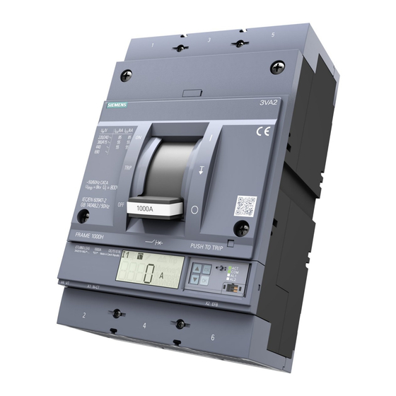
-
Contents
-
Table of Contents
-
Bookmarks
Quick Links
Related Manuals for Siemens Sentron 3VA
Summary of Contents for Siemens Sentron 3VA
-
Page 3: Manual, 01/2019, L1V30435333
___________________ Introduction ___________________ Description ___________________ SENTRON Applications ___________________ Accessories Protection devices 3VA molded case circuit breakers ___________________ with UL and IEC certification Service and maintenance ___________________ Technical specifications Manual ___________________ Appendix ESD guidelines ___________________ List of abbreviations ___________________ Conversion tables 01/2019 L1V30435333-01…
-
Page 4
Note the following: WARNING Siemens products may only be used for the applications described in the catalog and in the relevant technical documentation. If products and components from other manufacturers are used, these must be recommended or approved by Siemens. Proper transport, storage, installation, assembly, commissioning, operation and maintenance are required to ensure that the products operate safely and without any problems. -
Page 5: Table Of Contents
Table of contents Introduction ……………………….. 9 About this documentation ………………….9 Product-specific information ………………..10 1.2.1 Target readers ……………………10 1.2.2 Technical Support ……………………10 1.2.3 Reference documents ………………….11 Description ……………………….13 Overview — applications and portfolio ………………13 2.1.1 Applications and possible uses ………………..
-
Page 6
Table of contents 2.5.7 Ground-fault protection ………………….70 2.5.7.1 Measurement method 1: Vectorial summation (residual) current ………. 70 2.5.7.2 Measurement method 2: Direct detection …………….72 2.5.8 Neutral conductor protection (N) ……………….. 73 2.5.9 Zone-selective interlocking ZSI ………………..76 Thermal-magnetic trip unit ………………… 79 2.6.1 Thermal-magnetic trip unit (TMTU) ……………… -
Page 7
Table of contents Connection system ………………….. 168 4.3.1 Introduction ……………………… 168 4.3.2 General information about cables and busbars …………..168 4.3.3 Connection portfolio for 3VA UL molded case circuit breakers ……….172 4.3.3.1 General overview ……………………172 4.3.3.2 Front cable connection………………….176 4.3.3.3 Front busbar and compression lug connections ………….. -
Page 8
Table of contents 4.5.6.5 Locking, blocking and interlocking ………………290 4.5.7 Degree of protection ………………….291 4.5.7.1 IP degree of protection ………………….291 4.5.7.2 NEMA degree of protection ………………..291 4.5.8 Accessories …………………….. 292 4.5.8.1 Illumination kit ……………………292 Motor operator……………………293 4.6.1 Elements of the motor operator MO320 ……………. -
Page 9
Table of contents 4.11 Test devices …………………….. 360 4.11.1 Introduction ……………………… 360 4.11.2 The TD300 activation and trip box ………………361 4.11.2.1 Operation and execution of the tripping function …………..362 4.11.2.2 Technical specifications of TD300 ………………364 4.11.3 The TD500 test device ………………….364 4.11.3.1 General information, preparations ……………… -
Page 10
Table of contents 6.2.2.9 Test devices ……………………. 449 6.2.2.10 Door cover frame ……………………. 449 Power losses ……………………450 6.3.1 Power losses of 3VA5 molded case circuit breakers …………450 6.3.2 Power losses of 3VA6 molded case circuit breakers …………452 6.3.3 Power loses of 3VA UL molded case switches ………….. -
Page 11: Introduction
Introduction About this documentation 3VA molded case circuit breakers with UL 489 certification for the North American market The 3VA molded case circuit breakers from the portfolio of SENTRON protection, switching, measuring and monitoring devices ensure the reliable protection of people and property as integral components of efficient power distribution systems.
-
Page 12: Product-Specific Information
The sales contract contains the entire obligation of Siemens. The warranty contained in the contract between the parties is the sole warranty of Siemens. Any statements contained herein do not create new warranties or modify the existing warranty.
-
Page 13: Reference Documents
ATSE — Modbus Communication Protocol (http://support.automation.siemens.com/ WW/view/en/40761679) Grundlagen der Niederspannungsschalt- — — technik (Fundamentals of Low-Voltage Switchgear and Controlgear), Siemens AG © 2008 Hartmut Kiank, Wolfgang Fruth: ISBN: A19100-L531-B115 — Planungsleitfaden für Energieverteilungs- anlagen (Planning Guide for Power Distribution Plants), Publicis Publishing Schalten, Schützen, Verteilen in…
-
Page 14
Introduction 1.2 Product-specific information 3VA molded case circuit breakers with UL and IEC certification Manual, 01/2019, L1V30435333-01… -
Page 15: Description
Description Overview — applications and portfolio This chapter provides an overview of all 3VA molded case circuit breakers with certification according to the North American standard UL 489 (3VA UL) and shows the areas in which the various molded case circuit breakers are used. The topics discussed in this chapter are listed below: ●…
-
Page 16: Aspects Of The Ul Market — Low-Voltage Systems In The Usa
Aspects of the UL market — Low-voltage systems in the USA This chapter is an excerpt from the document «The secrets of UL». You will find the complete document under (http://w3app.siemens.com/mcms/infocenter/dokumentencenter/ce/Documentsu20Brochures /e20001-a820-p305-v2-7600.pdf). Low-voltage systems in the USA The usual system configurations in the USA are very different from those found in Europe.
-
Page 17
Description 2.1 Overview — applications and portfolio Electric circuits with «straight» and «slash» voltages In the USA, voltages are considered from the power supply company side or the secondary side of the power supply company transformers. The connection (wye or delta) of the electric circuit and the method of grounding play a major role here. -
Page 18: Portfolio
Description 2.1 Overview — applications and portfolio 2.1.3 Portfolio The integrated 3VA UL portfolio consists of two different ranges of molded case circuit breakers in five different rated operational current versions (frame sizes). Sizes The new 3VA UL molded case circuit breakers set new standards in flexibility and the variety of modular accessories available.
-
Page 19
Description 2.1 Overview — applications and portfolio 3VA5 molded case circuit breakers The new 3VA5 molded case circuit breakers reliably perform all the tasks required for line protection. Features The key features of the 3VA5 range are: ● Compact design ●… -
Page 20
Description 2.1 Overview — applications and portfolio 3VA6 molded case circuit breakers The new 3VA6 molded case circuit breakers reliably perform all the tasks required for line protection. This range is designed for applications with more exacting requirements: ● Increased breaking capacity ●… -
Page 21
Description 2.1 Overview — applications and portfolio Electronic trip unit (ETU) The current sensor of the 3VA6 molded case circuit breaker comprises an iron-cored transformer for the internal power supply and a Rogowski coil for precise sensing and measurement of the current values. Each of these transformers was specifically optimized for its task. -
Page 22
Description 2.1 Overview — applications and portfolio 100% rated versions of the 3VA UL molded case circuit breaker The US National Electrical Code, NEC recognizes two categories of overcurrent protective devices (OCPD) and has different required load calculations for their application. The two categories are standard OCPDs and OCPDs listed for operation at 100% of their rating (commonly referred to as «100 % rated»). -
Page 23: Detailed Information About Applications And Possible Uses
Description 2.1 Overview — applications and portfolio 2.1.4 Detailed information about applications and possible uses 3VA molded case circuit breakers with UL and IEC certification Manual, 01/2019, L1V30435333-01…
-
Page 24: Technical Specifications
Description 2.1 Overview — applications and portfolio 2.1.5 Technical specifications Applies to I 15 A to 90 A 100 A to 125 A 14 kA 40 A to 90 A 18 kA; 100 A to 125 A 14 kA 3VA molded case circuit breakers with UL and IEC certification Manual, 01/2019, L1V30435333-01…
-
Page 25
Description 2.1 Overview — applications and portfolio 3VA molded case circuit breakers with UL and IEC certification Manual, 01/2019, L1V30435333-01… -
Page 26
Description 2.1 Overview — applications and portfolio G alarm, no G protection (the G function sends an alarm message but does not trip the circuit breaker) Breaking capacities in combination with contactors (SCCR ratings) may differ Integrated instantaneous short-circuit release for self-protection The short-circuit current rating (SCCR rating) is the maximum permissible short-circuit current at the installation location of the MCS in combination with an appropriate additional overload protection device. -
Page 27
Description 2.1 Overview — applications and portfolio G alarm, no G protection (the G function sends an alarm message but does not trip the circuit breaker) Breaking capacities in combination with contactors (SCCR ratings) may differ Integrated instantaneous short-circuit release for self-protection The short-circuit current rating (SCCR rating) is the maximum permissible short-circuit current at the installation location of the MCS in combination with an appropriate short-circuit protection device. -
Page 28: Molded Case Circuit Breakers And Accessories In The System
Description 2.1 Overview — applications and portfolio 2.1.6 Molded case circuit breakers and accessories in the system The new 3VA UL molded case circuit breakers come with a large portfolio of accessory components that – depending on the type of accessory – can be flexibly installed internally or externally regardless of the size of circuit breaker.
-
Page 29
Description 2.1 Overview — applications and portfolio Overview of accessories in the system 3VA molded case circuit breakers with UL and IEC certification Manual, 01/2019, L1V30435333-01… -
Page 30: Ergonomic Design
Description 2.2 Ergonomic design Ergonomic design This chapter provides an overview of the ergonomic design features of the new 3VA UL molded case circuit breakers and explains what makes them so special. The topics discussed in this chapter are listed below: ●…
-
Page 31
Description 2.2 Ergonomic design When the 3VA UL molded case circuit breaker is in the OFF position, it ensures that the circuit is reliably disconnected in all current paths. The clearances dimensioned according to UL 489 ensure that, in the event of overvoltages between input and output, isolation is maintained. -
Page 32
Description 2.2 Ergonomic design Indication of breaker positions in the draw-out unit The picture below illustrates the colors used to indicate the breaker position in the draw-out unit: The breaker position is indicated in a window of the draw-out unit and is clearly color-coded, enabling immediate identification of the current position of the molded case circuit breaker. -
Page 33: Ergonomic Design Of Circuit Breakers, Handles And Control Elements
Description 2.2 Ergonomic design Motor operator for remote control 3VA UL molded case circuit breakers can also be controlled remotely. Whether the circuit breaker is controlled from «just» the other side of the closed panel door, or the breaker is switched on via a control room, operator panel, etc., is irrelevant.
-
Page 34
Description 2.2 Ergonomic design Clear status indication The possible breaker positions of manual rotary operators are listed below: ● ON — red marking ● TRIP — yellow marking ● OFF — green marking The handle clearly engages in one of these positions depending on the status of the molded case circuit breaker. -
Page 35
Description 2.2 Ergonomic design Operator kit with Bowden cable (Max-Flex operator) The Max-Flex operator is a hand lever operator for operating the breaker from the outside of the control panel. The handle is connected to the switching mechanism via a Bowden cable. Color-coded control elements The control elements on the thermal-magnetic and electronic trip units are color-coded. -
Page 36: Wide Range Of Accessories
Description 2.2 Ergonomic design 2.2.3 Wide range of accessories The internal accessories (e.g. alarm and auxiliary switches, auxiliary releases, etc.) all belong to one family and can be installed within the 3VA5 and 3VA6 ranges regardless of the circuit breaker size. Installation is carried out quickly and easily by simply snapping on and screwing the connecting cables Through color and mechanical coding and corresponding information found on the inside of the accessory cover, installation at the right place in the circuit breaker is ensured.
-
Page 37
Description 2.2 Ergonomic design A system of color coding has been used to clearly identify the specific functions of individual accessories: The cylinder lock and communication accessories shown next to the internal accessories are explained in chapters Locking and interlocking (Page 302) and Communication and system integration (Page 327). -
Page 38: Connection Technology
Description 2.2 Ergonomic design 2.2.4 Connection technology A large selection of terminals and connectors are available for the new range of 3VA UL molded case circuit breakers. The supported cable cross-sections are based on the size of the molded case circuit breaker and the cable terminals used.
-
Page 39
Description 2.2 Ergonomic design Cables and busbars The new range of 3VA UL molded case circuit breakers are designed for different cables and busbars: ● Different cable types, e.g. ① – Circular conductor — UL cable class Solid ② – Stranded — UL cable class B ③… -
Page 40: Technical Details
Description 2.3 Technical details Technical details This chapter provides an overview of the technical details of the 3VA UL molded case circuit breakers. The topics discussed in this chapter are listed below: ● Circuit breaker identification ● Operation ● Current limitation ●…
-
Page 41
Description 2.3 Technical details Circuit breaker labeling Each 3VA UL molded case circuit breaker is labeled with all UL-required information and is thus clearly identifiable: ① ④ «Connection information» adhesive label Adhesive label insert (in accessory compartment) ② ⑤ Connection socket for EFB300 external function «Detailed information on installed connection box and MMB300 maintenance mode box on technology»… -
Page 42
Description 2.3 Technical details Front panel: Labeling The following information is displayed on the front panel of the circuit breaker: ① ⑨ Circuit breaker designation Product version ② ⑩ UL Type Listing Circuit breaker article number (MLFB) ③ ⑪ CE approval mark Trip unit designation ④… -
Page 43
This code can be scanned with a smartphone or a tablet PC. For the full range of QR code functions, use the «Industry Support» app supplied free of charge by Siemens. All relevant product information regarding the molded case circuit breaker (e.g. operating instructions, characteristic curves, FAQs, etc.) can be quickly accessed and viewed in this… -
Page 44
Description 2.3 Technical details HACR type information HACR stands for heating, air conditioning and refrigeration. The information on the circuit breaker states that the protective device may be used for overcurrent protection of corresponding systems. HACR applications are a known example of installations with motor groups. Many modern heating systems operate with fans for exhaust air from combustion systems, exhaust control and ventilation systems for hot air. -
Page 45
Description 2.3 Technical details «Connection information» adhesive label The «Connection information» label is attached on the side and contains the following information: ① UL, CSA and NOM, as well as CE, CCC, etc. approval marks, if valid for this circuit breaker ②… -
Page 46
Description 2.3 Technical details 2D matrix code of production This is a production code that contains the article number of the device, production date, production facility and other information in encoded form. This code can also be scanned with the free «Industry Support» app for smartphone and tablet PC. -
Page 47
Description 2.3 Technical details «Detailed information on installed connection technology» adhesive label This adhesive label accompanies the various terminals. At this time, 3VA UL molded case circuit breakers can only be ordered without preassembled connection technology, i.e. connection terminals or terminal bars for the incoming and outgoing sides must be ordered separately for each circuit breaker. -
Page 48
Description 2.3 Technical details «Internal accessories» adhesive label You can make a note of the number of installed accessory components on the «Internal accessories» adhesive label. This will enable you to ascertain which accessories are installed without removing the accessory cover and to use the information, for example, to reorder components. -
Page 49: Operation
Description 2.3 Technical details 2.3.2 Operation ① ③ ON: Main contacts closed OFF: Main contacts open ② ④ TRIP: Switching position following a trip PUSH TO TRIP: A mechanical trip is initiated using the button The main contacts of the molded case circuit breakers are opened and closed by means of a handle mounted on the front of the unit.
-
Page 50: Current Limitation
Description 2.3 Technical details 2.3.3 Current limitation The term «current limitation» refers to the action of limiting the peak value of the prospective impulse short-circuit current i to a lower let-through current i The compact design of the breakers has been made possible by their excellent current limiting capabilities.
-
Page 51
Description 2.3 Technical details Rotary double-contact system To achieve excellent current limiting, the 3VA UL molded case circuit breakers are equipped with a rotary double-contact system that opens dynamically — on its own — above the specified disengaging currents, on the principle of magnetic repulsion, before the expected peak value of the short-circuit current is reached. -
Page 52: Standards And Guidelines
Description 2.4 Standards and guidelines Standards and guidelines This chapter provides you with an overview of the standards and guidelines that are met with the 3VA UL molded case circuit breakers The topics discussed in this chapter are listed below: ●…
-
Page 53: Certificates
(Derating (Page 454)). Please contact Siemens concerning operating conditions that are outside the values specified in the derating table. The permissible storage temperature in original Siemens packaging is between -40 °C and +80 °C. Special climatic requirements 3VA UL molded case circuit breakers can also be used under harsh conditions.
-
Page 54
Description 2.4 Standards and guidelines The following standards-related criteria are complied with: ● IEC / EN 60068-2-2 «Bd» and IEC / EN 60068-2-1 «Ab»: Temperature range: -25 °C … +70 °C ● IEC / EN 60068-2-30 «Db» Humid heat up to +55 °C and air humidity up to 95 % ●… -
Page 55: Permissible Mounting Positions And Mounting Positions With Accessories
Description 2.4 Standards and guidelines 2.4.4 Permissible mounting positions and mounting positions with accessories The tested mounting positions for 3VA UL molded case circuit breakers are illustrated below. Please adhere to local codes and standards for specific application regulations. 3VA51: A motor operator cannot be used with DIN rail mounting Not allowed by NEC 3VA molded case circuit breakers with UL and IEC certification Manual, 01/2019, L1V30435333-01…
-
Page 56: Safety Clearances (For Iec Applications)
Description 2.4 Standards and guidelines 2.4.5 Safety clearances (for IEC applications) During a short-circuit interruption, high temperatures, ionized gases and high pressures occur in and above the arcing chambers of the molded case circuit breaker. For this reason, defined minimum clearances must be adhered to during installation between the molded case circuit breakers and the mounting plates, conductor bars and other protection systems placed in the immediate vicinity.
-
Page 57
Description 2.4 Standards and guidelines Minimum clearance for 3VA5 molded case circuit breakers: Can be used for connection methods: box terminal, screw-type terminal, internal wire connector, and rear terminals Can be used for connection methods: wire connector large, bus connectors extended, and bus connectors offset Is not permitted in this voltage range for IEC applications Minimum clearance for 3VA6 molded case circuit breakers: Can be used for connection methods: box terminal, screw-type terminal, internal wire connector, and rear terminals… -
Page 58
Description 2.4 Standards and guidelines Note In addition to the clearances stated above, any insulating equipment that might be required must also be considered, see chapter Insulating equipment (Page 203). If the molded case circuit breaker is installed in a system whose connection type and operational voltage does not correspond to the specified insulation measures, a type test is required. -
Page 59
Description 2.4 Standards and guidelines Safety clearances between molded case circuit breakers Generally, no minimum clearance needs to be observed between the molded case circuit breakers placed side-by-side. For more details please refer to the relevant operating instructions of the circuit breakers. The following safety clearances apply to molded case circuit breakers installed directly on top of each other: See tables below for minimum clearance… -
Page 60
② Fixing of busbar Recommended maximum clearance for 3VA5 molded case circuit breakers The values for the 3VA5 molded case circuit breakers are available from Siemens on request. 3VA molded case circuit breakers with UL and IEC certification Manual, 01/2019, L1V30435333-01… -
Page 61: Breaker Venting
Description 2.4 Standards and guidelines Recommended maximum clearance for 3VA6 molded case circuit breakers: 2.4.6 Breaker venting Adequate venting space must be taken into account during planning and installation of the molded case circuit breakers. In particular, the following must be observed: ●…
-
Page 62: Minimum Enclosure Dimensions
Description 2.4 Standards and guidelines 2.4.7 Minimum enclosure dimensions The 3VA UL molded case circuit breakers are tested in appropriate steel enclosures as per UL 489. The minimum enclosure dimensions are summarized in the following tables by size. Minimum enclosure height Minimum enclosure width Minimum enclosure depth Minimum enclosure dimensions for 3VA5 molded case circuit breakers:…
-
Page 63: Ip Degrees Of Protection
Description 2.4 Standards and guidelines 2.4.8 IP degrees of protection The 3VA UL molded case circuit breakers meet the following IP protection classes as defined by IEC 60529 and IEC 60947-1, Annex C: Degree of protection IP30 is achieved when a 3VA UL molded case circuit breaker is installed in a switchboard with a door cutout including cover frame (see below).
-
Page 64: Environmental Protection
Description 2.4 Standards and guidelines 2.4.9 Environmental protection The 3VA UL molded case circuit breakers already meet the requirements of the European RoHS Directive 2011/65/EU (Restriction of the use of certain hazardous substances in electrical and electronical equipment) even though these products will not fall under this directive until July 22, 2019.
-
Page 65: Protection Functions
Description 2.5 Protection functions Protection functions This chapter provides an overview of the protection system of 3VA UL molded case circuit breakers. The topics discussed in this chapter are listed below: ● Description of functions ● Overload protection (L) ● Short-time delayed short-circuit protection (S) ●…
-
Page 66: Description Of Functions
Description 2.5 Protection functions 2.5.1 Description of functions The protection function performed by the molded case circuit breaker in the power distribution network is defined by the choice of trip unit. There are two different types of trip unit, i.e. thermal-magnetic (TMTU) and electronic (ETU): 3VA molded case circuit breakers with UL and IEC certification Manual, 01/2019, L1V30435333-01…
-
Page 67
Description 2.5 Protection functions 3VA molded case circuit breakers with UL and IEC certification Manual, 01/2019, L1V30435333-01… -
Page 68: Characteristic Curves
Description 2.5 Protection functions 2.5.2 Characteristic curves To design a low-voltage switchboard installation in accordance with the valid rules, the system planner needs to select the protection settings of the molded case circuit breakers. The settings selected for the trip unit of a molded case circuit breaker depend on the type of equipment to be protected, e.g.
-
Page 69: Guide To Setting The Tripping Characteristic
Description 2.5 Protection functions 2.5.3 Guide to setting the tripping characteristic Supplementary conditions The settings selected for the trip unit of a molded case circuit breaker depend on the technical environment (e.g. switchboard and applications) and the type of equipment to be protected.
-
Page 70: Overload Protection (L)
Description 2.5 Protection functions Setting the parameters for electronic trip units ETU 5-series and 8-series Trip units of the ETU 5-series and 8-series are equipped with an LCD display and operator buttons. These can be used to change the parameters. The powerconfig software can also be used to input parameter settings.
-
Page 71: Short-Time Delayed Short-Circuit Protection (S)
Description 2.5 Protection functions 2.5.5 Short-time delayed short-circuit protection (S) The ID letter for the short-time delayed short-circuit protection is «S» (stands for «Short-time (protection)»). The S function of the trip unit can be used to implement time-selective short- circuit tripping in low-voltage networks in which multiple molded case circuit breakers are installed in series.
-
Page 72: Ground-Fault Protection
Description 2.5 Protection functions 2.5.7 Ground-fault protection The ID letter for ground-fault protection is «G» (stands for «ground fault»). The G protection detects residual currents between phases and grounded, electrically conductive parts. The ground-fault protection function responds if the ground fault current exceeds the set tripping current I for the set delay period t Like for the short-time delayed short-circuit protection, the delay time of the ground fault…
-
Page 73
Description 2.5 Protection functions Ground-fault detection in unbalanced systems The neutral conductor current is measured directly and in the case of 3-pole molded case circuit breakers only for the ground-fault protection, but in the case of 4-pole circuit breakers the neutral conductor current is also evaluated for the neutral conductor protection. The trip unit calculates the ground-fault current using the three phase currents and the neutral conductor current for the vectorial summation. -
Page 74: Measurement Method 2: Direct Detection
Description 2.5 Protection functions 2.5.7.2 Measurement method 2: Direct detection In this case, an external current transformer is installed directly in the grounded neutral point of the transformer. When the set ground-fault current is reached, a message is directly output (ETU556 and ETU856) or the circuit breaker is tripped (ETU560 and ETU860). Note This measuring method must be activated explicitly in the ETU: On the display under menu item «GF M», switch over from «rES»…
-
Page 75: Neutral Conductor Protection (N)
Description 2.5 Protection functions 2.5.8 Neutral conductor protection (N) The ID letter for neutral conductor protection is «N». The neutral conductor protection system protects the neutral conductor against overloads and short circuits. The setting value of the current is designated with I , the associated setting time is identical to t Note…
-
Page 76
Description 2.5 Protection functions Neutral conductor protection With rated current I ≤ 40 A: I = 40 % … 100 % I With rated current I ≤ 100 A: I = 20% … 100% I Starting from rated current I ≥… -
Page 77
Description 2.5 Protection functions Example of a neutral conductor protection characteristic ① Response threshold of the neutral conductor protection ② Response threshold of the long-time delayed protection Adjustment of neutral conductor protection settings The tripping current I can be adjusted: ●… -
Page 78: Zone-Selective Interlocking Zsi
Backward compatibility The ZSI function of 3VA UL molded case circuit breakers is compatible with the ZSI functions of Siemens 3VL molded case circuit breakers and 3WL air circuit breakers. 3VA molded case circuit breakers with UL and IEC certification…
-
Page 79
Description 2.5 Protection functions Operating principle The diagram below demonstrates the operating principle of zone-selective interlocking: — — — Communication cable «Virtual» tripping time of I protection Output, transmits the blocking signal Delay time setting of S protection Input, receives the blocking signal Delay time of all molded case circuit breakers which detect the short circuit but do not receive a blocking signal when ZSI is activated… -
Page 80
Description 2.5 Protection functions Fault 1 If the short-circuit current is sufficiently large, the trip units of molded case circuit breakers Q41, Q33, Q22 and Q11 are activated. Since Q41 clears the fault within t = 10 ms, none of the other molded case circuit breakers trips even though Q41 has no ZSI and cannot therefore transmit a blocking signal to Q33. -
Page 81: Thermal-Magnetic Trip Unit
Description 2.6 Thermal-magnetic trip unit Thermal-magnetic trip unit 2.6.1 Thermal-magnetic trip unit (TMTU) A thermal-magnetic trip unit consists of a thermal trip unit for protecting against overload, and a magnetic trip unit for protecting against short circuits. Both trip units are series- connected.
-
Page 82: Electronic Trip Unit
Description 2.7 Electronic trip unit Electronic trip unit 2.7.1 Electronic trip unit (ETU) An electronic trip unit is based on the following concepts: ● Complete measurement of the current in the phases L1, L2 and L3, with N and currents to ground optional ●…
-
Page 83: Connections
One method to satisfy this requirement is to provide energy-reducing maintenance switching with local status indicator. The Siemens DAS when used with a remote external switch meets this requirement. 3VA6 molded case circuit breakers and Dynamic Arc Sentry All 3VA6 molded case circuit breakers are equipped with the Dynamic Arc Sentry mode (DAS mode).
-
Page 84
Description 2.7 Electronic trip unit All molded case circuit breakers with electronic trip units (ETUs 3-series, 5-series and 8- series) receive the signal for switchover of the protection parameters to DAS mode via the MMB300 maintenance mode box applied with the appropriate control scheme. You can find more information about the MMB300 maintenance mode box in chapter MMB300 maintenance mode box (Page 351). -
Page 85: Protection Functions
Description 2.7 Electronic trip unit 2.7.4 Protection functions Available in a version with external current transformer for N conductor or 4-pole breaker 3VA molded case circuit breakers with UL and IEC certification Manual, 01/2019, L1V30435333-01…
-
Page 86: Operator Controls
Description 2.7 Electronic trip unit 2.7.5 Operator controls The following figure shows the available ETU types of the 3VA6 molded case circuit breakers. You can decide which ETU to select according to the area of application. ① ③ ⑤ Name of the ETU Front interface Pushbuttons ②…
-
Page 87
Description 2.7 Electronic trip unit LED displays The following table explains what the LED displays mean: 3VA molded case circuit breakers with UL and IEC certification Manual, 01/2019, L1V30435333-01… -
Page 88
Description 2.7 Electronic trip unit ETU 3-series units 3-series electronic trip units are equipped with rotary selector switches. A description of the operating principle of the rotary selector switches and operating instructions can be found in chapter Guide to setting the tripping characteristic (Page 67). Displays on ETU 5-series and 8-series units 5-series and 8-series electronic trip units have an LCD display. -
Page 89
Description 2.7 Electronic trip unit The following table explains what functions are performed by the buttons next to the display: Displays on ETU 5-series and 8-series units The basic structure comprises the following displays: ● Standard display ● Alarm display ●… -
Page 90
Description 2.7 Electronic trip unit 3VA molded case circuit breakers with UL and IEC certification Manual, 01/2019, L1V30435333-01… -
Page 91
Description 2.7 Electronic trip unit Standard display Alarm display Active alarms are displayed consecutively in screens AV1 … AV5. If no alarms are active, these screens are concealed. 3VA molded case circuit breakers with UL and IEC certification Manual, 01/2019, L1V30435333-01… -
Page 92
Description 2.7 Electronic trip unit Measured value display The table below explains the measured value display: 3VA molded case circuit breakers with UL and IEC certification Manual, 01/2019, L1V30435333-01… -
Page 93
Description 2.7 Electronic trip unit Parameter display The table below explains the parameter display: Dependent on the rated current of the molded case circuit breaker and the ETU version 3VA molded case circuit breakers with UL and IEC certification Manual, 01/2019, L1V30435333-01… -
Page 94
Description 2.7 Electronic trip unit Setting and changing parameters 1. Use the arrow keys to navigate to the correct display. 2. Press the <OK> button. → Edit mode is active. Activation is confirmed by display of «pencil» symbol. 3. Use the arrow keys to adjust the parameter setting. 4. -
Page 95
Description 2.7 Electronic trip unit Diagnostics display When a TD500 test device is connected, you can use it to initiate a test. The following screen appears when a TD500 is connected. The bar flashes at a frequency of 0.5 Hz. The bar travels from left to right while testing is in progress. -
Page 96: Load Acceptance And Load Shedding — Load Management
Description 2.7 Electronic trip unit 2.7.6 Load acceptance and load shedding — load management 3VA UL molded case circuit breakers equipped with an ETU 3-series or higher series provide two current thresholds for the purpose of implementing a local load management function.
-
Page 97: Measuring With A Rogowski Coil
Description 2.7 Electronic trip unit 2.7.7 Measuring with a Rogowski coil The Rogowski coil is a toroidal coil without a ferromagnetic core. It is used as a component in electronic measuring devices to measure alternating current. Advantages of the current sensor: ●…
-
Page 98
Description 2.7 Electronic trip unit The following table provides an overview of the setting values: Depending on ETU version Value can be read Value can be edited 3VA molded case circuit breakers with UL and IEC certification Manual, 01/2019, L1V30435333-01… -
Page 99
Description 2.7 Electronic trip unit Depending on ETU version Value can be displayed/read 3VA molded case circuit breakers with UL and IEC certification Manual, 01/2019, L1V30435333-01… -
Page 100
Description 2.7 Electronic trip unit Depending on ETU version Value can be displayed/read 3VA molded case circuit breakers with UL and IEC certification Manual, 01/2019, L1V30435333-01… -
Page 101: Applications
Applications Use of the 3VA UL molded case circuit breakers in line protection 3.1.1 Applications in line protection The main applications of the circuit breakers as line protection components are: ● Feeder circuit breaker of machines ● Branch circuit breaker for predominantly resistive loads ●…
-
Page 102
Applications 3.1 Use of the 3VA UL molded case circuit breakers in line protection Suitable 3VA UL molded case circuit breakers and trip units 3VA UL molded case circuit breakers equipped with the following trip units are suitable for use in line protection: ●… -
Page 103
Applications 3.1 Use of the 3VA UL molded case circuit breakers in line protection Overview of the trip units 9th and 10th digit of article number, e.g. 3VA6115-5JP31-0AA0 Neutral conductor protection See Use of the 3VA UL molded case circuit breaker as a molded case switch (MCS) (Page 138) 0.5 (50%) cannot be set for molded case circuit breakers with rated operational current 40 A 0.2 (20%) cannot be set for molded case circuit breakers with rated operational current 40 A 3VA molded case circuit breakers with UL and IEC certification… -
Page 104: Versions Of The Trip Units
Applications 3.1 Use of the 3VA UL molded case circuit breakers in line protection 3.1.2 Versions of the trip units 3.1.2.1 Thermal-magnetic trip units TMTUs for line protection applications Derating Thermal-magnetic trip units employ a temperature-dependent bimetal to provide overload protection.
-
Page 105
Applications 3.1 Use of the 3VA UL molded case circuit breakers in line protection TM210 parameters: 3VA molded case circuit breakers with UL and IEC certification Manual, 01/2019, L1V30435333-01… -
Page 106
Applications 3.1 Use of the 3VA UL molded case circuit breakers in line protection Thermal-magnetic trip unit TM230 LI Line protection FTAM — function LI The thermal-magnetic trip unit TM230 has: ● Fixed parameter setting I for overload protection (L) ●… -
Page 107: Electronic Trip Units
Applications 3.1 Use of the 3VA UL molded case circuit breakers in line protection 3.1.2.2 Electronic trip units ETUs for line protection applications The following electronic trip units are suitable for use in line protection applications: ● ETU320 LI ● ETU330 LIG ●…
-
Page 108
Applications 3.1 Use of the 3VA UL molded case circuit breakers in line protection Line protection — function LI The electronic trip unit ETU320 has: ● Adjustable parameter settings I and t for overload protection (L) ● Adjustable parameter setting I for instantaneous short-circuit protection (I) ●… -
Page 109
Applications 3.1 Use of the 3VA UL molded case circuit breakers in line protection Long-time delay setting values — t Instantaneous pickup setting values — I Neutral current setting values — I 3VA molded case circuit breakers with UL and IEC certification Manual, 01/2019, L1V30435333-01… -
Page 110
Applications 3.1 Use of the 3VA UL molded case circuit breakers in line protection Overload protection L: Adjustable in 10 steps from 0.4 to 1.0 x I • 0.4 / 0.5 / 0.6 / 0.7 / 0.75 / 0.8 / 0.85 / 0.9 / 0.95 / 1.0 Adjustable in 10 steps from 0.5 to 12 /15 s or 17 s: •… -
Page 111
Applications 3.1 Use of the 3VA UL molded case circuit breakers in line protection Electronic trip unit ETU330 LIG ETU330 LIG 3-pole: ETU330 LIG 4-pole: Line protection — function LIG The electronic trip unit ETU330 has: ● Adjustable parameter settings I and t for overload protection (L) ●… -
Page 112
Applications 3.1 Use of the 3VA UL molded case circuit breakers in line protection Current setting values — I Long-time delay setting values — t Instantaneous pickup setting values — I 3VA molded case circuit breakers with UL and IEC certification Manual, 01/2019, L1V30435333-01… -
Page 113
Applications 3.1 Use of the 3VA UL molded case circuit breakers in line protection Ground fault pickup setting values — I Neutral current setting values — I Overload protection L: Adjustable in 10 steps from 0.4 to 1.0 x I •… -
Page 114
Applications 3.1 Use of the 3VA UL molded case circuit breakers in line protection Instantaneous short-circuit protection I: Adjustable in 10 steps from 1.5 to 9 / 10 / 11 / 12 x I (dependent on the frame • size) Ground-fault protection G: Adjustable in 5 steps of 0.2 / 0.25 / 0.4 / 0.6 to 1.0 x I •… -
Page 115
Applications 3.1 Use of the 3VA UL molded case circuit breakers in line protection Electronic trip unit ETU350 LSI ETU350 LSI 3-pole: ETU350 LSI 4-pole: Line protection — function LSI The electronic trip unit ETU350 has: ● Adjustable parameter settings I and t for overload protection (L) ●… -
Page 116
Applications 3.1 Use of the 3VA UL molded case circuit breakers in line protection Current setting values — I Long-time delay setting values — t Instantaneous pickup setting values — I 3VA molded case circuit breakers with UL and IEC certification Manual, 01/2019, L1V30435333-01… -
Page 117
Applications 3.1 Use of the 3VA UL molded case circuit breakers in line protection Short-time pickup setting values — I Short-time delay setting values — t Neutral current setting values — I 3VA molded case circuit breakers with UL and IEC certification Manual, 01/2019, L1V30435333-01… -
Page 118
Applications 3.1 Use of the 3VA UL molded case circuit breakers in line protection Overload protection L: Adjustable in 10 steps from 0.4 to 1.0 x I • 0.4 / 0.5 / 0.6 / 0.7 / 0.75 / 0.8 / 0.85 / 0.9 / 0.95 / 1.0 Adjustable in 10 steps from 0.5 to 12 /15 s or 17 s: •… -
Page 119
Applications 3.1 Use of the 3VA UL molded case circuit breakers in line protection 5-series and 8-series electronic trip units Parameter input via display unit With 5-series and 8-series electronic trip units, it is possible to set more parameters and scale the selection of parameters more finely than for 3-series trip units. -
Page 120
Applications 3.1 Use of the 3VA UL molded case circuit breakers in line protection Electronic trip unit ETU820 LI ETU820 LI 3-pole and 4-pole: Line protection — function LI The electronic trip unit ETU820 has: ● Adjustable parameter settings I and t for overload protection (L) ●… -
Page 121
Applications 3.1 Use of the 3VA UL molded case circuit breakers in line protection ETU820 parameters, 4-pole Overload protection L: Adjustable from 0.4 to 1.0 x I in absolute current values • = 40 A: In steps of 0.5 A ≥… -
Page 122
Applications 3.1 Use of the 3VA UL molded case circuit breakers in line protection Electronic trip unit ETU830 LIG ETU830 LIG 3-pole and 4-pole Line protection — function LIG The electronic trip unit ETU830 has: ● Adjustable parameter settings I and t for overload protection (L) ●… -
Page 123
Applications 3.1 Use of the 3VA UL molded case circuit breakers in line protection ETU830 parameters, 4-pole Overload protection L: Adjustable from 0.4 to 1.0 x I in absolute current values • = 40 A: In steps of 0.5 A ≥… -
Page 124
Applications 3.1 Use of the 3VA UL molded case circuit breakers in line protection Electronic trip units ETU550 LSI and ETU850 LSI ETU550 LSI 3-pole and 4-pole units: ETU850 LSI 3-pole and 4-pole units: Line protection — function LSI The electronic trip units ETU550 and ETU850 have: ●… -
Page 125
Applications 3.1 Use of the 3VA UL molded case circuit breakers in line protection ETU550 / ETU850 parameters (3-pole version): only 3-pole version with external current transformer for N conductor ETU550 / ETU850 parameters (4-pole version): Overload protection L: Adjustable from 0.4 to 1.0 x I in absolute current values •… -
Page 126
Applications 3.1 Use of the 3VA UL molded case circuit breakers in line protection Short-time delayed short circuit protection S: Adjustable from 0.6 to 9 / 10 x I • < 40 A: In steps of 0.5 A ≥ 100 A: In steps of 1 A Adjustable from 0.05 to 0.5 s: •… -
Page 127
Applications 3.1 Use of the 3VA UL molded case circuit breakers in line protection Electronic trip units ETU556 LSI G (alarm-only) and ETU856 LSI G (alarm-only) ETU556 LSI(G) 3-pole and 4-pole: ETU856 LSI(G) 3-pole and 4-pole: Line protection — function LSI(G) The electronic trip units ETU556 and ETU856 have: ●… -
Page 128
Applications 3.1 Use of the 3VA UL molded case circuit breakers in line protection ETU556 / ETU856 parameters, 3-pole: only 3-pole version with external current transformer for N conductor ETU556 / ETU856 parameters, 4-pole: Overload protection L: Adjustable from 0.4 to 1.0 x I in absolute current values •… -
Page 129
Applications 3.1 Use of the 3VA UL molded case circuit breakers in line protection Short-time delayed short circuit protection S: Adjustable from 0.6 to 9 / 10 x I • = 40 A: In steps of 0.5 A ≥ 100 A: In steps of 1 A Adjustable from 0.05 to 0.5 s •… -
Page 130
Applications 3.1 Use of the 3VA UL molded case circuit breakers in line protection Electronic trip units ETU560 LSIG and ETU860 LSIG ETU560 LSIG 3-pole and 4-pole units: ETU860 LSIG 3-pole and 4-pole units: Line protection — function LSIG The electronic trip units ETU560 and ETU860 have: ●… -
Page 131
Applications 3.1 Use of the 3VA UL molded case circuit breakers in line protection ETU560 / ETU860 parameters (3-pole version): only 3-pole version with external current transformer for N conductor ETU560 / ETU860 parameters (4-pole version): Overload protection L: Adjustable from 0.4 to 1.0 x I in absolute current values •… -
Page 132
Applications 3.1 Use of the 3VA UL molded case circuit breakers in line protection Short-time delayed short circuit protection S: Adjustable from 0.6 to 9 / 10 x I • = 40 A: In steps of 0.5 A ≥ 100 A: In steps of 1 A Adjustable from 0.05 to 0.5 s •… -
Page 133
Applications 3.1 Use of the 3VA UL molded case circuit breakers in line protection Neutral conductor protection N: The neutral conductor protection function is available only for 3-pole molded case circuit breakers with external current transformer for N conductor for 4-pole molded case circuit breakers. -
Page 134: Overview Of 3Va Ul Molded Case Circuit Breakers In Line Protection
Applications 3.1 Use of the 3VA UL molded case circuit breakers in line protection 3.1.3 Overview of 3VA UL molded case circuit breakers in line protection Applies to I 15 A to 90 A 100 A to 125 A 14 kA 40 A to 90 A 18 kA;…
-
Page 135
Applications 3.1 Use of the 3VA UL molded case circuit breakers in line protection For the rated ultimate short-circuit breaking capacity and rated service short-circuit breaking capacity with direct current, see chapter Use of 3VA UL molded case circuit breaker in DC systems (Page 141) . -
Page 136: Use As Motor Circuit Protector (Mcp) For Starter Combinations
These can be specially matched to the motor. Siemens offers two versions of the 3VA UL motor circuit protectors: ● Magnetic trip units from the 3VA5 series in sizes 125 A and 250 A with a magnetic setting range from 3 to 12 x I ●…
-
Page 137
For the relevant short-circuit current ratings (SCCR ratings) of the combination of contactor and overload relay, please refer to the corresponding UL certificates for contactor and overload relay. These can be found in the Service and Support Portal (https://support.industry.siemens.com/cs/ww/en/view/29755649). 3VA molded case circuit breakers with UL and IEC certification Manual, 01/2019, L1V30435333-01… -
Page 138
Applications 3.2 Use as Motor Circuit Protector (MCP) for starter combinations TM120M magnetic trip unit Starter protection (motor circuit protector) AM — function I The TM120M magnetic trip unit has an adjustable short circuit release I TM120M parameters: 3VA molded case circuit breakers with UL and IEC certification Manual, 01/2019, L1V30435333-01… -
Page 139
Applications 3.2 Use as Motor Circuit Protector (MCP) for starter combinations ETU310M electronic trip unit ETU310M 3-pole ETU310M parameters: The parameters are selected with the setting knob. The diagram below shows the possible selections. The values for the respective setting are listed in the following table. Instantaneous short-circuit protection I: ●… -
Page 140: Use Of The 3Va Ul Molded Case Circuit Breaker As A Molded Case Switch (Mcs)
Applications 3.3 Use of the 3VA UL molded case circuit breaker as a molded case switch (MCS) Use of the 3VA UL molded case circuit breaker as a molded case switch (MCS) Molded case switches are used as: ● Disconnectors in subdistribution and final distribution boards ●…
-
Page 141
Applications 3.3 Use of the 3VA UL molded case circuit breaker as a molded case switch (MCS) Technical specifications of molded case switch 2-pole circuit breaker in 3-pole frame The short-circuit current rating (SCCR rating) is the maximum permissible short-circuit current at the installation location of the molded case switch when a corresponding overload protection device is used Integrated instantaneous short-circuit release for self-protection… -
Page 142: Compatibility Of 3Va Ul Molded Case Switch And Accessories
Applications 3.3 Use of the 3VA UL molded case circuit breaker as a molded case switch (MCS) 3.3.1 Compatibility of 3VA UL molded case switch and accessories The 3VA UL molded case switches are derived from the molded case circuit breakers and share the following: ●…
-
Page 143: Use Of 3Va Ul Molded Case Circuit Breaker In Dc Systems
Applications 3.4 Use of 3VA UL molded case circuit breaker in DC systems Use of 3VA UL molded case circuit breaker in DC systems 3.4.1 Introduction The main applications for 3VA circuit breakers in DC installations or systems are: ● Public transport systems, e.g. electric cars, underground rail networks and streetcars ●…
-
Page 144: Variants
Applications 3.4 Use of 3VA UL molded case circuit breaker in DC systems 3.4.2 Variants The same thermal-magnetic trip units used as line protection devices in AC installations are also available for protecting DC installations. However, a correction factor must be applied to the magnetic trip unit, relative to the actual current rating.
-
Page 145: Breaking Capacity With Direct Current
Applications 3.4 Use of 3VA UL molded case circuit breaker in DC systems 3.4.3 Breaking capacity with direct current 3VA molded case circuit breakers with UL and IEC certification Manual, 01/2019, L1V30435333-01…
-
Page 146: Recommended Circuits For Dc Systems Ul
Applications 3.4 Use of 3VA UL molded case circuit breaker in DC systems 3.4.4 Recommended circuits for DC systems UL 3VA molded case circuit breakers with UL and IEC certification Manual, 01/2019, L1V30435333-01…
-
Page 147
Applications 3.4 Use of 3VA UL molded case circuit breaker in DC systems Note 2-pole version in 3-pole frame (2(3)-pole) Only the outer poles may be used (pole 1/2 and pole 5/6). 3VA molded case circuit breakers with UL and IEC certification Manual, 01/2019, L1V30435333-01… -
Page 148: Recommended Circuits For Dc Systems Iec
Applications 3.4 Use of 3VA UL molded case circuit breaker in DC systems 3.4.5 Recommended circuits for DC systems IEC Ground-fault monitoring 750 V DC is not a listed voltage according to UL 489 Note DC 2-pole (all-pole disconnection), grounded system The grounded pole must always be assigned to the individual conducting path, so that in the event of a ground fault there are always 2 conducting paths in series in a circuit with 3-pole molded case circuit breakers, and 3 conducting paths in series in a circuit with 4-pole molded…
-
Page 149
Applications 3.4 Use of 3VA UL molded case circuit breaker in DC systems Note 2-pole version in 3-pole frame (2(3)-pole) Only the outer poles may be used (pole 1/2 and pole 5/6). Further circuits are available on request. See also Insulating equipment (Page 203) 3VA molded case circuit breakers with UL and IEC certification Manual, 01/2019, L1V30435333-01… -
Page 150: Use Of 3Va Ul Molded Case Circuit Breakers In It Systems According To Iec 60947-2
The Siemens 3VA UL molded case circuit breakers for line protection, with thermal-magnetic and electronic trip units, are suitable for use in IT systems.
-
Page 151: Fault Situation
Applications 3.5 Use of 3VA UL molded case circuit breakers in IT systems according to IEC 60947-2 3.5.3 Fault situation The most critical fault for molded case circuit breakers in ungrounded IT systems is a double-phase-to-ground fault on the infeed and load ends of the molded case circuit breaker. If this fault occurs, the entire phase-to-phase voltage is applied across one pole of the molded case circuit breaker.
-
Page 152
Applications 3.5 Use of 3VA UL molded case circuit breakers in IT systems according to IEC 60947-2 3VA molded case circuit breakers with UL and IEC certification Manual, 01/2019, L1V30435333-01… -
Page 153: Accessories
Accessories Overview — Accessories for 3VA UL molded case circuit breakers You can adapt the 3VA UL molded case circuit breakers to their respective tasks with a comprehensive range of accessories. The table below shows the 3VA UL molded case circuit breakers in which the accessories can be installed and which sizes are covered by the same accessory component: 3VA molded case circuit breakers with UL and IEC certification Manual, 01/2019, L1V30435333-01…
-
Page 154: Internal Accessories
Accessories 4.2 Internal accessories Internal accessories 4.2.1 Mounting locations of 3VA UL molded case circuit breakers The portfolio of internal accessories includes: ● Auxiliary switches ● Alarm switches ● Auxiliary releases ● COM060 communication module ● 24 V module ● Cylinder lock (type Ronis) The following tables show the alternative mounting locations for internal accessories, which depend on the size and pole number of the circuit breaker.
-
Page 155
Accessories 4.2 Internal accessories 3VA5 molded case circuit breakers: 3VA molded case circuit breakers with UL and IEC certification Manual, 01/2019, L1V30435333-01… -
Page 156
Accessories 4.2 Internal accessories 3VA6 molded case circuit breakers: 3VA molded case circuit breakers with UL and IEC certification Manual, 01/2019, L1V30435333-01… -
Page 157
Accessories 4.2 Internal accessories 3VA molded case circuit breakers with UL and IEC certification Manual, 01/2019, L1V30435333-01… -
Page 158: Auxiliary And Alarm Switches
Accessories 4.2 Internal accessories 4.2.2 Auxiliary and alarm switches The auxiliary and alarm switches for the 3VA UL molded case circuit breaker form a single family. They can be installed in all sizes of all circuit breakers up to 600 A. The auxiliary and alarm switches can be very simply snapped into place and connected up in accessory compartments provided on the front panel of the unit to the left and right of the handle.
-
Page 159
Accessories 4.2 Internal accessories The diagram below uses the example of an ET200S to illustrate the conventional method of connecting the electronics-compatible auxiliary switch AUX, the trip alarm switch TAS and the motor operator MO320 to a distributed I/O unit. Further information about contact reliability can be found at the end of this chapter. -
Page 160
Accessories 4.2 Internal accessories Electrical alarm switches EAS Electrical alarm switches are operated as soon as the main contacts of the molded case circuit breaker open in the event that the breaker is tripped by the ETU. They indicate the following conditions: ●… -
Page 161: Contact Sequence Diagrams
Accessories 4.2 Internal accessories 4.2.3 Contact sequence diagrams Main contacts open Auxiliary contacts open Contacts closed 3VA molded case circuit breakers with UL and IEC certification Manual, 01/2019, L1V30435333-01…
-
Page 162: Technical Specifications Of Auxiliary And Alarm Switches
Accessories 4.2 Internal accessories 4.2.4 Technical specifications of auxiliary and alarm switches Safe separation in the case of side-by-side construction of auxiliary switches and auxiliary releases only up to 440 V and in systems up to an impulse voltage withstand level of 4 kV HP switches without adjacent switches;…
-
Page 163
Accessories 4.2 Internal accessories In combination with manual switching operations, but not when motor operators are used 3VA molded case circuit breakers with UL and IEC certification Manual, 01/2019, L1V30435333-01… -
Page 164: Auxiliary Releases
Accessories 4.2 Internal accessories 4.2.5 Auxiliary releases Auxiliary releases allow remote electrical tripping of the circuit breaker. They can be used to monitor control or main circuits in order to implement a protective system against accidental restart following a power failure, for example. Auxiliary releases therefore perform a main circuit monitoring function in addition to the main circuit monitoring performed by the trip unit.
-
Page 165
Accessories 4.2 Internal accessories Shunt Trip Left (STL) Shunt trips of type STL can be fitted in the left-hand accessory compartment as an alternative to an undervoltage release. The units are available with six rated voltages in the following range: ●… -
Page 166
Accessories 4.2 Internal accessories Technical specifications of shunt trips and releases 3VA molded case circuit breakers with UL and IEC certification Manual, 01/2019, L1V30435333-01… -
Page 167
Accessories 4.2 Internal accessories 3VA molded case circuit breakers with UL and IEC certification Manual, 01/2019, L1V30435333-01… -
Page 168: Time-Delay Devices For Undervoltage Releases
Accessories 4.2 Internal accessories 4.2.6 Time-delay devices for undervoltage releases Undervoltage releases can also be equipped with external, electronic time-delay control devices which prevent unintentional tripping in response to brief voltage dips during periods of disrupted operation. Time-delay device for UVR with fixed delay setting The simple time-delay device with fixed delay setting is available for the following voltages: ●…
-
Page 169: 24 V Module
Accessories 4.2 Internal accessories 4.2.8 24 V module With the aid of the 24 volt module, the ETU electronic trip unit of the 3VA6 molded case circuit breakers can be permanently activated. The module is installed in the right-hand accessory compartment and has 4 slots. The following advantages arise from the use of the 24 V module: ●…
-
Page 170: Connection System
Accessories 4.3 Connection system Connection system 4.3.1 Introduction The chapter «Connection technology» contains useful information and provides an overview of the 3VA UL connection technology. It provides a helpful guide to connecting cables or busbars to a molded case circuit breaker and so helps to ensure the safety of personnel and material assets.
-
Page 171
Accessories 4.3 Connection system Cable classes according to UL 486 and IEC 60228: UL 486 IEC 60228 ① Cable with solid wire in core Solid Class 1 ② Cable with stranded wires in core Class B Class 2 ③ Cable with stranded wires in core Class C Class 5 ④… -
Page 172
Accessories 4.3 Connection system Solid and stranded sector-shaped conductors are also used. Compression lugs For stable and reliable connecting of cables to molded case circuit breakers, compression lugs are also used. These elements help to make solid connections at the breaker. Insulation is first stripped from the end of the cable (by amount of length L) before the compression lug is attached to the cable. -
Page 173
Accessories 4.3 Connection system Cables and busbars: Busbars In addition to cables, the busbar is also widely used in electrical connections, especially in panels. Some of the reasons for using busbars include: ● High-curvature bending radii which are unsuitable for cables of large cross section ●… -
Page 174: Connection Portfolio For 3Va Ul Molded Case Circuit Breakers
Accessories 4.3 Connection system 4.3.3 Connection portfolio for 3VA UL molded case circuit breakers 4.3.3.1 General overview The connection technology of the 3VA UL molded case circuit breakers provides a straightforward and convenient way to commission the molded case circuit breakers in compliance with all installation requirements.
-
Page 175
Accessories 4.3 Connection system The connection technology accessories (see chapter Further connection accessories (Page 203)) also provide the option of insulating the termination area of the 3VA UL molded case circuit breaker and protecting it from accidental contact. A control wire tap can be implemented quickly using accessory components which are available separately. -
Page 176
Accessories 4.3 Connection system Copper terminal available Only available for 3VA63 and 3VA64 3VA molded case circuit breakers with UL and IEC certification Manual, 01/2019, L1V30435333-01… -
Page 177
Accessories 4.3 Connection system Note Wire connectors are generally made of aluminum. For special wire connectors, there are copper versions. Exact cross-section and torque information for these can be found in chapter Front cable connection (Page 176). For designs and applications for 100% rated line protection, copper wire connectors without control wire tap must be used. -
Page 178: Front Cable Connection
Accessories 4.3 Connection system 4.3.3.2 Front cable connection The diagram below illustrates all the components available for implementing a direct cable connection at the molded case circuit breaker. The only exception is the box terminal as this can be used to connect busbars as well as cables. Connection technology Cables and busbars ①…
-
Page 179
Accessories 4.3 Connection system Box terminal The tables below show all the types and sizes of cable and flexible busbar that can be connected to a box terminal. 3VA5 molded case circuit breakers: 3VA molded case circuit breakers with UL and IEC certification Manual, 01/2019, L1V30435333-01… -
Page 180
Accessories 4.3 Connection system 3VA6 molded case circuit breakers: Maximum current carrying capacity 380 A Box terminals can be ordered ● as a pack of 3 ● as a pack of 4 3VA molded case circuit breakers with UL and IEC certification Manual, 01/2019, L1V30435333-01… -
Page 181
Accessories 4.3 Connection system Wire connector with and without control wire tap The wire connector is available under separate article numbers depending on whether it is ordered with or without a control wire tap. With the exception of the hole for the control wire tap, both wire connectors are technically identical, i.e. -
Page 182
Accessories 4.3 Connection system 3VA5 molded case circuit breakers: Aluminum version: 3VA molded case circuit breakers with UL and IEC certification Manual, 01/2019, L1V30435333-01… -
Page 183
Accessories 4.3 Connection system Copper version: 3VA molded case circuit breakers with UL and IEC certification Manual, 01/2019, L1V30435333-01… -
Page 184
Accessories 4.3 Connection system 3VA6 molded case circuit breakers: Aluminum version: Maximum current carrying capacity 400 A 3VA molded case circuit breakers with UL and IEC certification Manual, 01/2019, L1V30435333-01… -
Page 185
Accessories 4.3 Connection system Copper version: Wire connector with and without control wire tap can be ordered: ● as a pack of 3 ● as a pack of 4 3VA molded case circuit breakers with UL and IEC certification Manual, 01/2019, L1V30435333-01… -
Page 186
Accessories 4.3 Connection system Wire connector, large, with and without control wire tap The wire connector, large, is available under separate article numbers depending on whether it is ordered with or without a control wire tap. With the exception of the hole for the control wire tap, both wire connectors are technically identical, i.e. -
Page 187
Accessories 4.3 Connection system Wire connector, large with or without control wire tap can be ordered: ● as a pack of 3 ● as a pack of 4 3VA molded case circuit breakers with UL and IEC certification Manual, 01/2019, L1V30435333-01… -
Page 188
Accessories 4.3 Connection system Wire connector, 2 cables, with and without control wire tap The wire connector, 2 cables, is available under separate article numbers depending on whether it is ordered with or without a control wire tap. With the exception of the hole for the control wire tap, both wire connectors are technically identical, i.e. -
Page 189
Accessories 4.3 Connection system Aluminum version: 3VA molded case circuit breakers with UL and IEC certification Manual, 01/2019, L1V30435333-01… -
Page 190
Accessories 4.3 Connection system Copper version: Wire connector, 2 cables with or without control wire tap can be ordered ● as a pack of 3 ● as a pack of 4 3VA molded case circuit breakers with UL and IEC certification Manual, 01/2019, L1V30435333-01… -
Page 191
Accessories 4.3 Connection system Distribution wire connector, 6 cables The distribution wire connector, 6 cables, is an external terminal that projects beyond the molded case circuit breaker contour of the termination area. It can hold up to 6 cables. One of the six holes in the terminal can be used to implement a control wire tap. -
Page 192
Accessories 4.3 Connection system 3VA6 molded case circuit breakers: The distribution wire connector, 6 cables, can be ordered: ● as a pack of 3 ● as a pack of 4 3VA molded case circuit breakers with UL and IEC certification Manual, 01/2019, L1V30435333-01… -
Page 193: Front Busbar And Compression Lug Connections
Accessories 4.3 Connection system 4.3.3.3 Front busbar and compression lug connections The diagram below illustrates all the components available for implementing a busbar or compression lug connection on the front panel of the 3VA UL molded case circuit breaker. Connection technology Cables and busbars ①…
-
Page 194
Accessories 4.3 Connection system Nut keeper kit With the nut keeper kit, it is possible to connect busbars and compression lugs directly to the terminal of the 3VA UL molded case circuit breaker. An auxiliary connection can be implemented using a special control wire tap. You can find more detailed information about this in chapter Control wire tap (Page 219). -
Page 195
Accessories 4.3 Connection system Nut keeper kits can be ordered: ● as a pack of 3 ● as a pack of 4 3VA molded case circuit breakers with UL and IEC certification Manual, 01/2019, L1V30435333-01… -
Page 196
Accessories 4.3 Connection system Front bus connectors extended The front bus connectors extended enable larger busbars and compression lugs to be connected outside the termination area of a 3VA UL molded case circuit breaker. The front bus connectors therefore extend the terminal of the breaker. You can find information on the required insulation measures in chapter Insulating equipment (Page 203). -
Page 197
Accessories 4.3 Connection system The front bus connectors extended can be ordered: ● as a pack of 3 ● as a pack of 4 3VA molded case circuit breakers with UL and IEC certification Manual, 01/2019, L1V30435333-01… -
Page 198
Accessories 4.3 Connection system Front bus connectors offset (only available for 3VA63 and 3VA64) The front bus connectors offset enable very large busbars and compression lugs to be connected outside the termination area of a 3VA UL molded case circuit breaker. The front bus connector offset increases the distance between pole centers (3VA63 and 3VA64 with offset = 70 mm / 2.76 inch) of the terminals of the molded case circuit breaker. -
Page 199
Accessories 4.3 Connection system Front bus connectors offset can be ordered: ● as a pack of 3 ● as a pack of 4 3VA molded case circuit breakers with UL and IEC certification Manual, 01/2019, L1V30435333-01… -
Page 200: Rear Busbar And Compression Lug Connections
Accessories 4.3 Connection system 4.3.3.4 Rear busbar and compression lug connections The diagram below illustrates all the components available for implementing a busbar or compression lug connection on the rear panel of the 3VA UL molded case circuit breaker. Connection technology Cables and busbars ①…
-
Page 201
Accessories 4.3 Connection system Width across flats of the supplied lock nut Plug-in and draw-out technology only possible in combination with bus connector offset and associated terminal cover 3VA molded case circuit breakers with UL and IEC certification Manual, 01/2019, L1V30435333-01… -
Page 202
Accessories 4.3 Connection system Rear connection studs round can be ordered ● as a pack of 3 (2 short studs and 1 long stud) ● as a pack of 4 (2 short studs and 2 long studs) ● as a pack of 1 (1 short stud) ●… -
Page 203
Accessories 4.3 Connection system Plug-in and draw-out technology only possible in combination with bus connector offset and associated terminal cover 3VA molded case circuit breakers with UL and IEC certification Manual, 01/2019, L1V30435333-01… -
Page 204
Accessories 4.3 Connection system Rear connection studs flat can be ordered: ● as a pack of 3 (2 short connection studs flat and 1 long connection stud flat) ● as a pack of 4 (2 short connection studs flat and 2 long connection studs flat) ●… -
Page 205: Further Connection Accessories
Accessories 4.3 Connection system 4.3.4 Further connection accessories 4.3.4.1 Insulating equipment The connection technology accessories provide a comprehensive range of insulation measures. The following overview shows the insulation accessories available for the 3VA UL molded case circuit breakers. ① Terminal cover ②…
-
Page 206
Accessories 4.3 Connection system Phase barriers Phase barriers provide insulation between the individual phases of the molded case circuit breaker. They are simply snapped into place on the 3VA UL molded case circuit breaker. Phase barriers can be used in combination with the insulating plate and the insulating plate offset. -
Page 207
Accessories 4.3 Connection system Terminal cover, extended terminal cover, and offset terminal cover Note The offset terminal cover is only available for the 3VA63 and 3VA64 molded case circuit breakers. All terminal covers provide IP40 protection at the front of the breaker and IP20 protection at the infeed and load ends provided that they are correctly installed (cutting of grille structure). -
Page 208
Accessories 4.3 Connection system Terminal cover The terminal cover is compatible with: ● Box terminals ● Wire connectors ● Nut keeper kits The terminal cover is simply snapped into place on the 3VA UL molded case circuit breaker (3VA5 125 A) or snapped into place and secured with 2 screws (3VA5 250 A and 3VA6). Terminal cover extended ①… -
Page 209
Accessories 4.3 Connection system Terminal cover offset The terminal cover offset always consists of two parts: ① Rear insulating plate, provides insulation from the panel mounting plate ② Front half, pushed over the molded case circuit breaker from the front The insulating plate is fitted to the rear panel of the molded case circuit breaker and then secured by 2 screws to the front half of the terminal cover. -
Page 210
Accessories 4.3 Connection system General insulating measures 3VA molded case circuit breakers with UL and IEC certification Manual, 01/2019, L1V30435333-01… -
Page 211
Accessories 4.3 Connection system Insulating measures — UL The insulation accessories for UL applications are presented by identification letters in the following tables. Note All the presented insulation measures represent minimum requirements. Covers can be replaced with more substantial covers: •… -
Page 212
Accessories 4.3 Connection system Insulating measures for 3VA51 molded case circuit breakers for UL use Not applicable for 3VA51..-.ED1. 3VA molded case circuit breakers with UL and IEC certification Manual, 01/2019, L1V30435333-01… -
Page 213
Accessories 4.3 Connection system Insulating measures for 3VA52 molded case circuit breakers for UL use 3VA molded case circuit breakers with UL and IEC certification Manual, 01/2019, L1V30435333-01… -
Page 214
Accessories 4.3 Connection system Insulating measures for 3VA61/62/63/64 molded case circuit breakers for UL use For 3VA63/64 only 3VA molded case circuit breakers with UL and IEC certification Manual, 01/2019, L1V30435333-01… -
Page 215
Accessories 4.3 Connection system The insulating measures for IEC applications are presented in the following. The insulating measures are identified with letters in the tables. These letters stand for the following insulation accessories: Note All the presented insulation measures represent minimum requirements. Covers can be replaced with higher-quality covers: •… -
Page 216
Accessories 4.3 Connection system Insulating measures for 3VA51 molded case circuit breakers for IEC use Not applicable for 3VA51..-.ED1. 3VA molded case circuit breakers with UL and IEC certification Manual, 01/2019, L1V30435333-01… -
Page 217
Accessories 4.3 Connection system Insulating measures for 3VA52 molded case circuit breakers for IEC use 3VA molded case circuit breakers with UL and IEC certification Manual, 01/2019, L1V30435333-01… -
Page 218
Accessories 4.3 Connection system Insulating measures for 3VA61 and 3VA62 molded case circuit breakers for IEC use 3VA molded case circuit breakers with UL and IEC certification Manual, 01/2019, L1V30435333-01… -
Page 219
Accessories 4.3 Connection system Insulating measures for 3VA63 and 3VA64 molded case circuit breakers for IEC use 3VA molded case circuit breakers with UL and IEC certification Manual, 01/2019, L1V30435333-01… -
Page 220
Accessories 4.3 Connection system Touch protection Insulated cables and busbars With insulated cables and busbars whose insulation extends inside the termination area of the 3VA molded case circuit breaker, finger safety according to IP2X degree of protection is achieved in IEC applications with the terminal cover. The requirements of NFPA 79 «Protection against electric shock»… -
Page 221: Control Wire Tap
Accessories 4.3 Connection system 4.3.4.2 Control wire tap The portfolio of the 3VA UL molded case circuit breaker enables easy implementation of a control wire tap. Note A maximum current limit of 15 A applies to all control wire taps for 3VA UL molded case circuit breakers.
-
Page 222
Accessories 4.3 Connection system All wire connectors can be ordered with control wire tap under a separate article number. The wire connector is then supplied with a hole for the control wire tap. A ring terminal can be applied using this hole and, in some cases, a spade plug-in connector. The required screw is supplied. -
Page 223: Plug-In And Draw-Out Technology
Accessories 4.4 Plug-in and draw-out technology Plug-in and draw-out technology 4.4.1 Introduction In most applications, 3VA UL molded case circuit breakers are fixed-mounted in switchboards or distribution panels. The breaker is normally secured by mounting screws directly to the mounting plate or other suitable supports inside the panel. The cables or busbars of the main circuits are connected directly to the 3VA UL molded case circuit breaker with various terminals or connectors.
-
Page 224
Accessories 4.4 Plug-in and draw-out technology Draw-out technology As with plug-in technology, with draw-out technology, the 3VA UL molded case circuit breaker is equipped with plug-in contacts for the main circuits. In addition, side walls including guide and retaining studs are screwed onto the side of the molded case circuit breakers. -
Page 225
Accessories 4.4 Plug-in and draw-out technology Plug-in and draw-out technology for 3VA UL The following describes the interplay of plug-in and draw-out technology and 3VA UL molded case circuit breakers. However, the 3VA UL molded case switch (MCS) and motor circuit protector (MCP) types can also be implemented with plug-in or draw-out technology. -
Page 226: Overview Of Variants / Products
Accessories 4.4 Plug-in and draw-out technology 4.4.2 Overview of variants / products Installation overview 3-pole and 4-pole 3VA UL molded case circuit breaker versions are available for fixed mounting as well as for plug-in or draw-out technology according to the following table: Besides the complete kit for plug-in or draw-out technology, a «conversion kit»…
-
Page 227: General Information
Accessories 4.4 Plug-in and draw-out technology 4.4.3 General information With plug-in and draw-out circuit breakers, the cables or busbars are connected to the plug-in socket or the draw-out socket. The same socket unit is used for the same sizes of both variants.
-
Page 228: Information About Installation, Built-On And Built-In Components
Accessories 4.4 Plug-in and draw-out technology 4.4.4 Information about installation, built-on and built-in components Securing plug-in and draw-out units to the mounting plate Bolts supplied with complete kit Supplied with each complete kit for plug-in or draw-out technology: ● 4 fastening bolts, metric thread, Phillips pan head The fastening bolts are used to attach the relevant socket unit to a mounting plate or supports.
-
Page 229: Plug-In Technology
Accessories 4.4 Plug-in and draw-out technology 4.4.5 Plug-in technology 4.4.5.1 Product description Applications The plug-in units for the 3VA UL molded case circuit breakers are designed for complex applications in which fast replacement of the molded case circuit breaker is needed. Plug-in technology can be used, for example, when clear visual evidence of safe electrical isolation of circuits is essential, e.g.
-
Page 230
Accessories 4.4 Plug-in and draw-out technology A complete kit for plug-in technology contains all the components for conversion of a fixed-mounted molded case circuit breaker type to a plug-in technology type. A complete kit for plug-in technology contains: ● Plug-in socket ●… -
Page 231
Accessories 4.4 Plug-in and draw-out technology Scope of delivery of the 3VA UL molded case circuit breaker, 3VA UL molded case switch (MCS) and motor circuit protector (MCP): 2 assembly bolts • For 3-pole version up to 250 A: 4 assembly bolts •… -
Page 232
Accessories 4.4 Plug-in and draw-out technology Terminal covers As described above, two screw-mounted terminal covers are included in the plug-in socket complete kit and the plug-in socket conversion kit. These feature molded grips to ease withdrawal of the molded case circuit breaker from its socket. Since more force is needed to remove a molded case circuit breaker from its socket, the plug-in technology terminal covers are screwed to the molded case circuit breaker. -
Page 233
Accessories 4.4 Plug-in and draw-out technology Auxiliary circuit connectors Molded case circuit breakers are frequently equipped with internal accessories, e.g. auxiliary switches, auxiliary releases, etc. A broad range of components is also available for the 3VA UL molded case circuit breaker. For further information, please refer to chapter Internal accessories (Page 152). -
Page 234
Accessories 4.4 Plug-in and draw-out technology Position signaling in the plug-in socket Several position signaling switches (number depends on socket size) can be fitted in the plug-in socket. Auxiliary switches are capable of signaling «Plug-in unit — MCCB correctly bolted to plug-in socket» via electrical connections. For further information, please refer to chapter Position signaling switches (Page 244). -
Page 235: Combination With Other Accessories
Accessories 4.4 Plug-in and draw-out technology Benefits of plug-in technology ● Defective molded case circuit breakers can be replaced quickly and easily ● Clear visual evidence of safe electrical isolation of main circuits with removal of the circuit breaker ● Remote signaling of molded case circuit breaker positions: –…
-
Page 236: Draw-Out Technology
Accessories 4.4 Plug-in and draw-out technology 4.4.6 Draw-out technology 4.4.6.1 Product description Typical applications for draw-out units for the 3VA UL molded case circuit breaker range are installations in which inspections need to be carried out at regular intervals and a visible electrical isolation is required by removal of the circuit breaker, which must be implemented quickly.
-
Page 237
Accessories 4.4 Plug-in and draw-out technology Defined positions ● CONNECT position: The molded case circuit breaker is connected to the main circuits. The auxiliary circuits are also electrically connected to the installation via the auxiliary circuit connectors. This is the normal operating position of the molded case circuit breaker. ●… -
Page 238
Accessories 4.4 Plug-in and draw-out technology Remove the molded case circuit breaker NOTICE Irreparable damage to the racking mechanism when rotated in wrong direction The following operations will lead to irreparable damage of the draw-out socket gear: • Molded case circuit breaker is in DISCONNECT position: Insertion of the crank handle (position indicator changes to UNBLOCK) and counterclockwise turning of the crank handle toward DISCONNECT. -
Page 239
Accessories 4.4 Plug-in and draw-out technology Components of a conversion kit for draw-out technology ● Plug-in contacts for attachment to the main terminals of the molded case circuit breaker – 3-pole: 6 plug-in contacts – 4-pole: 8 plug-in contacts ● Side walls with guide bolts for mounting on the molded case circuit breaker ●… -
Page 240
Accessories 4.4 Plug-in and draw-out technology Installation instructions The draw-out socket is permanently mounted in the panel by means of the mounting screws included in the complete kit for draw-out technology. The molded case circuit breaker / molded case switch comes with two assembly screws (3-pole version) or four assembly screws (4-pole version). -
Page 241
Accessories 4.4 Plug-in and draw-out technology The plunger performs various safety functions in operation: ● It prevents closure of the main contacts of the molded case circuit breaker when the breaker is inserted in the draw-out socket and in an undefined position (breaker status indication is UNBLOCK). -
Page 242
Accessories 4.4 Plug-in and draw-out technology Position signaling in the draw-out socket Several position signaling switches can be inserted in the right side wall of the draw-out socket. These auxiliary switches are capable of signaling breaker positions DISCON, TEST and CONNECT. The auxiliary switches also output a position indication signal if the molded case circuit breaker in the draw-out socket is not in one of the positions specified above. -
Page 243
Accessories 4.4 Plug-in and draw-out technology Attaching padlocks 1. Move the molded case circuit breaker into the CONNECT, TEST or DISCON position. The breaker must be in one of these positions before the plastic frame can be pulled out. 2. Pull out the plastic frame. The crank handle opening is sealed off. -
Page 244
Accessories 4.4 Plug-in and draw-out technology Integration of molded case circuit breaker position signal into a communication network By means of the COM100 and COM800 breaker data servers, various statuses of multiple molded case circuit breakers can be queried and passed on by bus systems. This includes messages such as «Breaker tripped», «Breaker on», «Breaker off», reason for tripping, etc. -
Page 245: Combination With Other Accessories
Accessories 4.4 Plug-in and draw-out technology walls and the cutout. Optimum results are achieved here by additionally attaching a cover frame (Page 378). An opening in the panel through which the crank handle can be inserted must be provided in addition to the cutout for the door feedthrough.
-
Page 246: Accessories For Plug-In And Draw-Out Units
Accessories 4.4 Plug-in and draw-out technology 4.4.7 Accessories for plug-in and draw-out units 4.4.7.1 Description of individual product variants Position signaling switches These auxiliary switches are capable of signaling a variety of states via electrical connections. The position signaling switch is available in only one version. Applications: ●…
-
Page 247
Accessories 4.4 Plug-in and draw-out technology Signal «Position of molded case circuit breaker in the draw-out unit» So that the position of the molded case circuit breaker within the draw-out socket can be passed on electrically to the monitoring and control systems, up to six position signaling switches can be inserted in the right side wall of the draw-out unit at the following positions: ①… -
Page 248
Accessories 4.4 Plug-in and draw-out technology Depending on the position of the molded case circuit breaker in the draw-out unit, the outputs of the position signaling switches assume one of the following states: Signal «Draw-out unit locked / open» ① Slot for position signaling switch for signal «Draw-out unit locked / open»… -
Page 249
Accessories 4.4 Plug-in and draw-out technology Signal «Draw-out unit locked / open» A position signaling switch to transmit this signal is installed in position 44 of the right-hand side wall of the draw-out unit. A position signaling switch in position 44 outputs a signal which indicates whether the padlock locking unit is in the OUT position, thereby locking the draw-out unit. -
Page 250
Accessories 4.4 Plug-in and draw-out technology Signal «Plug-in unit — MCCB correctly bolted to plug-in socket» This option is provided for plug-in units only. Depending on the socket size, up to two position signaling switches can be installed in slot No. 46. ①… -
Page 251
Accessories 4.4 Plug-in and draw-out technology Communications interface for draw-out unit The cable set for the communication link for the draw-out unit consists of a preassembled cable with a mini USB port at one end and three special position signaling switches at the other. -
Page 252
For detailed instructions on how to install the communication link for the draw-out unit, please refer to the relevant Operating Instructions (https://support.industry.siemens.com/cs/ww/en/view/109741015). For instructions on how to read out data via remote data transfer, refer to the operating instructions for the COM100/COM800 breaker data server. -
Page 253
Accessories 4.4 Plug-in and draw-out technology ① Socket-end auxiliary circuit connector ② Breaker-end auxiliary circuit connector ③ Cable cage Cable cages are used to attach the breaker-end half of the auxiliary circuit connector to the underside of the molded case circuit breaker. Slot numbers are also printed on the cable cages. -
Page 254
Accessories 4.4 Plug-in and draw-out technology ① Positioning tongue (breaker end) ② Positioning hook (socket end) ③ Latching element (socket end) The socket-end half of the auxiliary circuit connectors is simply snapped into the socket. Various cable routing openings and ducts are provided in the socket and the molded case circuit breaker. -
Page 255
Accessories 4.4 Plug-in and draw-out technology Door feedthrough Door feedthroughs must be installed for applications which require ● direct operation of a molded case circuit breaker even when the panel door is closed, ● the draw-out version of a molded case circuit breaker to be electrically isolated from or connected to the installation while the panel door is closed, ●… -
Page 256
Accessories 4.4 Plug-in and draw-out technology Terminal cover for a molded case circuit breaker converted to plug-in or draw-out technology ① Terminal cover with molded grips, can be screwed to contact unit ② Terminal cover for covering the terminal area ①… -
Page 257
Accessories 4.4 Plug-in and draw-out technology Cable cage Cable cages are used to attach the breaker-end half of auxiliary circuit connectors to the molded case circuit breaker. They are also designed to act as cable ducts for installing wires from internal accessories to the auxiliary circuit connector. For further information about cable cages, please refer to chapter Auxiliary circuit connector (Page 250). -
Page 258: Overview Of Technical Specifications
Accessories 4.4 Plug-in and draw-out technology 4.4.7.2 Overview of technical specifications Technical specifications of the accessories for internal components of molded case circuit breakers in plug-in and draw-out technology: This meets NFPA 79 «Protection against electric shock» requirements This meets NFPA 79 «Protection against electric shock» requirements 3VA molded case circuit breakers with UL and IEC certification Manual, 01/2019, L1V30435333-01…
-
Page 259: Combination With Other Accessories
Accessories 4.4 Plug-in and draw-out technology 4.4.7.3 Combination with other accessories ● The communication link for the draw-out unit and the switches for signaling the position of the molded case circuit breaker in the draw-out unit are mutually compatible. For further information, please refer to the following chapters: Position signaling switches (Page 244) Communications interface for draw-out unit (Page 249)
-
Page 260: Manual Operators
Accessories 4.5 Manual operators Manual operators 4.5.1 Introduction The manual operators for the 3VA UL molded case circuit breaker are described in this chapter. Overview of manual operators The following manual operators are available for the 3VA UL molded case circuit breaker: ●…
-
Page 261: Operator Control Of The 3Va Ul Molded Case Circuit Breakers With Manual Operators
Accessories 4.5 Manual operators 4.5.2 Operator control of the 3VA UL molded case circuit breakers with manual operators Opening and closing ● To close the 3VA UL molded case circuit breaker: Turn the manual operator to the ON (I) position. Front mounted rotary operator, door mounted rotary operator, side wall mounted rotary operator: Handle of the operator kit with Bowden cable:…
-
Page 262
Accessories 4.5 Manual operators ● To open the 3VA UL molded case circuit breaker: Turn the manual operator to the OFF (O) position. Front mounted rotary operator, door mounted rotary operator, side wall mounted rotary operator: Handle of the operator kit with Bowden cable: 3VA molded case circuit breakers with UL and IEC certification Manual, 01/2019, L1V30435333-01… -
Page 263
Accessories 4.5 Manual operators Resetting the manual operator after the molded case circuit breaker has tripped When the molded case circuit breaker trips, the manual operator moves automatically from the ON (I) to the TRIP position. Front mounted rotary operator, door mounted rotary operator, side wall mounted rotary operator: Handle of the operator kit with Bowden cable: 3VA molded case circuit breakers with UL and IEC certification… -
Page 264
Accessories 4.5 Manual operators The molded case circuit breaker remains in the tripped state until the manual operator is reset: 1. Clear the fault which has caused the molded case circuit breaker to trip. 2. Turn the manual operator counter-clockwise to the RESET position (just beyond OFF (O)). -
Page 265
Accessories 4.5 Manual operators 3. Turn the manual operator to the ON (I) position. Front mounted rotary operator, door mounted rotary operator, side wall mounted rotary operator: Handle of the operator kit with Bowden cable: The molded case circuit breaker is closed again. 3VA molded case circuit breakers with UL and IEC certification Manual, 01/2019, L1V30435333-01… -
Page 266: Front Mounted Rotary Operator
Accessories 4.5 Manual operators 4.5.3 Front mounted rotary operator 4.5.3.1 Elements of the front mounted rotary operator The front mounted rotary operator is available in two versions: ● With door interlock ● Without door interlock ① ⑥ Front mounted rotary operator with door Indication of the breaker status (on, off, trip) interlock (see below)
-
Page 267: Front Mounted Rotary Operator With Door Interlock
Accessories 4.5 Manual operators Indication of the breaker status on front mounted rotary operator ① ④ ON: Breaker closed OFF: Breaker open ② ⑤ TRIP: Breaker tripped RESET: Reset following a trip ③ Mounting position 4.5.3.2 Front mounted rotary operator with door interlock The front mounted rotary operator with door interlock projects through the panel door.
-
Page 268
Accessories 4.5 Manual operators Procedure 1. Turn the front mounted rotary operator to position OFF (0) in order to open the molded case circuit breaker. 2. Press the button of the door open function 3. Actuate the NC contact of the panel door and open the panel door. Overriding the door interlock The door interlock can be overridden by a deliberate action. -
Page 269: Testing The Tripping Mechanism
Accessories 4.5 Manual operators 4.5.3.3 Testing the tripping mechanism Testing the tripping mechanism The button <PUSH TO TRIP> can be pressed to perform a function test on the tripping mechanism. Procedure 1. Turn the front mounted rotary operator to position ON (I) in order to close the molded case circuit breaker.
-
Page 270: Locking, Blocking And Interlocking
Accessories 4.5 Manual operators 4.5.3.4 Locking, blocking and interlocking The following accessories for locking, blocking and interlocking are used: ● Locking at the handle ● Locking, blocking and interlocking at the rotary operator Locking at the handle The rotary operator can be locked at the handle with up to three padlocks with a diameter of 3/16″…
-
Page 271
Accessories 4.5 Manual operators Locking, blocking and interlocking at the rotary operator Locking at the rotary operator is possible with up to three padlocks with a diameter of 3/16″ — 5/16″ / 5 — 8 mm and with a cylinder lock (type Ronis). Interlocking is only possible with a cylinder lock (type Ronis). -
Page 272
Accessories 4.5 Manual operators Locking, blocking or interlocking with cylinder lock (type Ronis) The cylinder lock (type Ronis) is used, depending on the installation of the cylinder lock holder, for locking, blocking and interlocking the rotary operators. ● Locking with cylinder lock (type Ronis): The cylinder lock (type Ronis) locks the rotary operators in the OFF (O) position. -
Page 273: Door Mounted Rotary Operator
Accessories 4.5 Manual operators 4.5.4 Door mounted rotary operator 4.5.4.1 Elements of the door mounted rotary operator With the door mounted rotary operator installed, it is possible to operate the molded case circuit breaker through the panel door without opening the door. ①…
-
Page 274: Door Interlock With Door Mounted Rotary Operator
Accessories 4.5 Manual operators 4.5.4.2 Door interlock with door mounted rotary operator Door interlock with door mounted rotary operator In the case of door mounted rotary operators with door interlock, the door is interlocked as soon as the switch is in ON (I) position. In the case of door mounted rotary operators with door open function, the door is interlocked starting from the closing of the door (OFF (0)).
-
Page 275
The panel door can then also be opened at any time without additional measures if the circuit breaker is switched on (position ON). This applies to all door mounted rotary operators with article numbers 3VA9…-0FK2… For details, see operating instructions (https://support.industry.siemens.com/cs/ww/en/view/109741016). 3VA molded case circuit breakers with UL and IEC certification Manual, 01/2019, L1V30435333-01… -
Page 276: Tolerance Compensator
Accessories 4.5 Manual operators 4.5.4.3 Tolerance compensator Tolerance compensator Door mounted rotary operators are supplied as standard with a tolerance compensator. This tolerance compensator compensates for a possible small misalignment between the handle in the panel door and the shaft of the door mounted rotary operator. ①…
-
Page 277: Testing The Tripping Mechanism
Accessories 4.5 Manual operators 4.5.4.4 Testing the tripping mechanism Testing the tripping mechanism The <PUSH TO TRIP> button can be used to check whether the tripping mechanism is working properly. Procedure 1. Turn the door mounted rotary operator to the OFF (O) position. 2.
-
Page 278: Supplementary Handle For Door Mounted Rotary Operator
Accessories 4.5 Manual operators 4.5.4.5 Supplementary handle for door mounted rotary operator Supplementary handle for door mounted rotary operator The supplementary handle can be used to operate the molded case circuit breaker when the panel door is open. The supplementary handle is mandatory for applications requiring NFPA 79-compliant door mounted rotary operators.
-
Page 279: Variable Depth Adapter
Accessories 4.5 Manual operators 4.5.4.6 Variable depth adapter Variable depth adapter The variable depth adapter enables adjustment of the travel distance CONNECT, TEST and DISCONNECT when using draw-out technology. As a result, the panel door does not have to be opened to move the switch to the CONNECT, TEST and DISCONNECT positions. See also chapter Draw-out technology (Page 234).
-
Page 280: Locking, Blocking And Interlocking
Accessories 4.5 Manual operators 4.5.4.7 Locking, blocking and interlocking The following accessories for locking, blocking and interlocking are used: ● Locking at the handle ● Locking at the masking plate of the panel door ● Locking, blocking and interlocking at the rotary operator Locking at the handle The rotary operator can be locked at the handle with up to three padlocks with a diameter of 3/16″…
-
Page 281
Accessories 4.5 Manual operators Locking at the masking plate of the panel door with cylinder lock (Kaba) The door mounted rotary operator can be locked at the panel door with a cylinder lock (type Kaba). The cylinder lock can not be used for locking in the ON (I) position. Note The cylinder lock (type Kaba) for the masking plate must be ordered separately. -
Page 282
Accessories 4.5 Manual operators Example of rotary operator with shaft stub: Lockable positions: ● Position OFF (O) Locking, blocking or interlocking with cylinder lock (type Ronis) The cylinder lock (type Ronis) is used, depending on the installation of the cylinder lock holder, for locking, blocking and interlocking the rotary operators. -
Page 283: Side Wall Mounted Rotary Operator
Accessories 4.5 Manual operators 4.5.5 Side wall mounted rotary operator 4.5.5.1 Elements of the side wall mounted rotary operator The side wall mounted rotary operator allows the molded case circuit breaker to be operated through the right-hand or left-hand side wall of the panel. ①…
-
Page 284: Side Wall Mounted Rotary Operator With Mounting Plate
Accessories 4.5 Manual operators 4.5.5.2 Side wall mounted rotary operator with mounting plate Side wall mounted rotary operator with mounting plate The side wall mounted rotary operator is available in a version with mounting plate for molded case circuit breakers up to 250 A. The mounting plate can be installed on the right- hand or left-hand side panel.
-
Page 285: Locking, Blocking And Interlocking
Accessories 4.5 Manual operators 4.5.5.3 Locking, blocking and interlocking The following accessories for locking, blocking and interlocking are used: ● Locking at the handle ● Locking at the masking plate of the side wall ● Locking, blocking and interlocking at the rotary operator Locking at the handle The rotary operator can be locked at the handle with up to three padlocks with a diameter of 3/16″…
-
Page 286
Accessories 4.5 Manual operators Locking at the masking plate of the side wall with cylinder lock (Kaba) The side wall mounted rotary operator can be locked at the side wall with a cylinder lock (type Kaba). The cylinder lock can not be used for locking in the ON (I) position. Note The cylinder lock (type Kaba) for the masking plate must be ordered separately. -
Page 287
Accessories 4.5 Manual operators Example of rotary operator with shaft stub: Lockable positions: ● Position OFF (O) Locking, blocking or interlocking with cylinder lock (type Ronis) The cylinder lock (type Ronis) is used, depending on the installation of the cylinder lock holder, for locking, blocking and interlocking the rotary operators. -
Page 288: Operator Kit With Bowden Cable (Max-Flex Operator)
Accessories 4.5 Manual operators 4.5.6 Operator kit with Bowden cable (Max-Flex operator) 4.5.6.1 Elements of the operator kit with Bowden cable The Max-Flex operator is installed for switching a 3VA UL molded case circuit breaker using a handle and Bowden cable through the panel door. The switching mechanism and handle are connected to one another with a flexible Bowden cable.
-
Page 289: Door Interlocking With The Operator Kit With Bowden Cable
Accessories 4.5 Manual operators 4.5.6.2 Door interlocking with the operator kit with Bowden cable The handle of the operator kit with Bowden cable interlocks the panel door as soon as the handle is in position ON (I). Defeat function of the door interlock In order to open the panel door even when the molded case circuit breaker is closed, the door interlock can be defeated.
-
Page 290
Accessories 4.5 Manual operators Switching on the molded case circuit breaker when panel door is open When the panel door is open, the 3VA UL molded case circuit breaker can be switched using the Max-Flex operator with a deliberate action only. Procedure 1. -
Page 291: Testing The Tripping Mechanism
Accessories 4.5 Manual operators 4.5.6.3 Testing the tripping mechanism The <PUSH TO TRIP> button can be used to check whether the tripping mechanism is working properly. Procedure 1. Turn the Max-Flex handle to the OFF (O) position. 2. Open the panel door. 3.
-
Page 292: Locking, Blocking And Interlocking
Accessories 4.5 Manual operators 4.5.6.5 Locking, blocking and interlocking Lockable positions: ● Position OFF (O) Locking the handle of the operator kit with Bowden cable in the OFF (O) position prevents the molded case circuit breaker from being closed. ● Position ON (I) The handle of the operator kit with Bowden cable can not be locked in the ON position.
-
Page 293: Degree Of Protection
Accessories 4.5 Manual operators 4.5.7 Degree of protection 4.5.7.1 IP degree of protection When fitted with a cover frame (see illustration below), a front mounted rotary operator installed in the panel door has degree of protection IP30. Note To ensure that the panel door can still be opened, the front mounted rotary operator must not project over the cover frame by more than 5 mm when the door is closed.
-
Page 294: Accessories
Accessories 4.5 Manual operators 4.5.8 Accessories 4.5.8.1 Illumination kit Illumination kit The illumination kit illuminates the indication of the breaker status of the front mounted rotary operator or the door mounted rotary operator or the masking plate of the door mounted or side wall mounted rotary operator.
-
Page 295: Motor Operator
Accessories 4.6 Motor operator Motor operator 4.6.1 Elements of the motor operator MO320 The motor operator MO320 transmits commands via electrical control cables to open and close the molded case circuit breaker. The source of commands transmitted via electrical control cables can be a pushbutton or a PLC, for example. Motor operators must also used in conjunction with automatic transfer control devices.
-
Page 296: Description Of Front Panel
Accessories 4.6 Motor operator 4.6.2 Description of front panel The front panel of the motor operator MO320 features an indication of the breaker status and an LED labeled «TRIP». The indication directly reflects the status of the actuating shaft. With its clear breaker status indication, the motor operator MO320 meets the requirements pertaining to isolating features stipulated by IEC / EN 60947-1.
-
Page 297: Manual, Auto And Lock Modes
Accessories 4.6 Motor operator 4.6.3 MANUAL, AUTO and LOCK modes The motor operator MO320 is switched to MANUAL or AUTO mode when the plastic window is opened (MANUAL) or closed (AUTO). MANUAL: When the plastic window is open, the motor operator MO320 is in MANUAL mode. The motor operator is moved to position ON (I) or OFF (O) by manual operation of the handle.
-
Page 298: Operating The Molded Case Circuit Breaker With Motor Operator
Accessories 4.6 Motor operator The padlock device can be locked with up to three padlocks with a diameter of 3/16″ — 5/16″ / 5 — 8 mm. Padlocks are not included in the scope of supply. 4.6.4 Operating the molded case circuit breaker with motor operator Opening and closing in MANUAL mode The plastic window is open, the motor operator is in MANUAL mode.
-
Page 299
Accessories 4.6 Motor operator Opening and closing in AUTO mode The plastic window is closed, the motor operator is in AUTO mode. The 3VA UL molded case circuit breaker can be closed or opened with electrical signals. ● Close the 3VA UL molded case circuit breaker with an electrical ON signal at the terminal block: The molded case circuit breaker is closed — ON (I). -
Page 300
Accessories 4.6 Motor operator Resetting the molded case circuit breaker If the 3VA UL molded case circuit breaker is tripped, the «TRIP» LED lights up ① Reset mode setting The resetting of the 3VA UL molded case circuit breaker by the motor operator depends on the selected reset mode. -
Page 301
Accessories 4.6 Motor operator Connection diagram for control of the motor operator MO320 Note An EMERGENCY OFF circuit may be implemented by means of a shunt trip or UVR (Page 162). For further circuit diagrams, see chapter «Circuit diagrams» (Page 385). The motor operator MO320 is edge-controlled, i.e. -
Page 302: Faults, Causes Of Faults And Rectification Of Faults
Accessories 4.6 Motor operator 4.6.5 Faults, causes of faults and rectification of faults 3VA molded case circuit breakers with UL and IEC certification Manual, 01/2019, L1V30435333-01…
-
Page 303: Technical Specifications
Accessories 4.6 Motor operator 4.6.6 Technical specifications Motor operator MO320 3VA molded case circuit breakers with UL and IEC certification Manual, 01/2019, L1V30435333-01…
-
Page 304: Locking And Interlocking
Accessories 4.7 Locking and interlocking Locking and interlocking 4.7.1 General information 4.7.1.1 General information For all 3VA UL molded case circuit breakers, a basic distinction is made between: ● Locking of molded case circuit breakers ● Interlocking of molded case circuit breakers 4.7.1.2 Locking The padlock devices can be used to lock the 3VA UL molded case circuit breaker in the…
-
Page 305: Interlocking
Accessories 4.7 Locking and interlocking Locking a molded case circuit breaker in the ON (I) position Like the OFF (O) position, the ON (I) positions can also be secured with a padlock device in order to secure the 3VA UL molded case circuit breaker against being opened. Only an authorized person can remove the locking of the 3VA UL molded case circuit breaker in the ON position again.
-
Page 306
Accessories 4.7 Locking and interlocking Principle of two interlocked 3VA UL molded case circuit breakers: ① Molded case circuit breaker blocked/locked in the safe switching state OFF (O) ② Molded case circuit breaker released for operation The 3VA UL molded case circuit breakers provide the following interlocking options: ●… -
Page 307: Blocking And Locking
Note You can find information on installation in the operating instructions «Handle blocking device» (https://support.industry.siemens.com/cs/ww/en/view/109742929). With the help of the handle blocking device, the 3VA UL molded case circuit breaker can be locked in the OFF (O) position with up to three padlocks (shackle diameter 3/16″ — 5/16″ / 4.5 — 8.5 mm).
-
Page 308
Accessories 4.7 Locking and interlocking If the 3VA UL molded case circuit breaker also needs to be lockable in the ON (I) position, ① the metal pin on the sliding bar must be removed with pliers, see diagram below. This deliberate action is a safety precaution and prevents accidental locking of the breaker in the ON position. -
Page 309: Cylinder Locks For Locking The 3Va Molded Case Circuit Breaker
Accessories 4.7 Locking and interlocking 4.7.2.2 Cylinder locks for locking the 3VA molded case circuit breaker The OFF (O) or ON (I) position of the 3VA UL molded case circuit breaker can also be locked with a cylinder lock (type Ronis). After the locking, the 3VA UL molded case circuit breaker is protected from further actuation.
-
Page 310
Accessories 4.7 Locking and interlocking ● One adapter kit The adapter kit transfers the motion of the lock to the switching mechanism. The article number includes the adapter kit and two cylinder lock housings. One cylinder lock housing (locking) is used for locking applications and the other housing (interlocking) for interlocking applications. -
Page 311
Accessories 4.7 Locking and interlocking Locking in the OFF (O) position In order to lock the 3VA UL molded case circuit breaker in the OFF (O) position, the cylinder lock (type Ronis) is installed with the adapter kit and the cylinder lock housing for locking in the right-hand accessory compartment of the molded case circuit breaker. -
Page 312
Accessories 4.7 Locking and interlocking To lock the 3VA UL molded case circuit breaker in the OFF (O) position, the key must be turned to the vertical «locked» position. Locking in the ON (I) position For safety reasons, a deliberate action is required to lock the breaker in the ON (I) position. The slide for locking in the ON position must be used for this purpose. -
Page 313: Front Interlocking
Accessories 4.7 Locking and interlocking 4.7.3 Front interlocking Front interlocks are installed on the front panel of the 3VA UL molded case circuit breaker. The following interlocking methods are available for the 3VA UL molded case circuit breaker: ● Cylinder locks for implementing interlocks between an unlimited number of molded case circuit breakers ●…
-
Page 314
Accessories 4.7 Locking and interlocking ● One adapter kit The adapter kit transfers the motion of the lock to the switching mechanism. The article number includes the adapter kit and two cylinder lock housings. ① Slide for locking in the OFF position ②… -
Page 315
Accessories 4.7 Locking and interlocking Installing the cylinder lock in the accessory compartment The cylinder lock (type Ronis) is installed with the adapter kit and the «Interlocking» cylinder lock housing in the right-hand accessory compartment of the molded case circuit breaker. ①… -
Page 316
Accessories 4.7 Locking and interlocking Interlocking of molded case circuit breakers WARNING Risk of interlock defeat. Use of more than one key poses safety hazard. Leave a key inserted in only one of the circuit breakers in the interlock arrangement. Store all other keys in a safe place or lock them away. -
Page 317
Accessories 4.7 Locking and interlocking 3. Insert one single key in one circuit breaker included in the interlock; store or lock away all other keys. 4. Use the single key to turn the cylinder lock of the 3VA UL molded case circuit breaker to be released to the «unlocked»… -
Page 318: Cable Interlock Module Using A Bowden Cable
Accessories 4.7 Locking and interlocking Installation of other accessories The installation of the cylinder lock in the accessory compartment of the molded case circuit breaker partly excludes the installation of other accessory components, e.g. front mounted accessories such as manual and motor operators as well as front interlocks. Likewise the cylinder lock blocks slots for internal accessories (for overview see chapter Mounting locations of 3VA UL molded case circuit breakers (Page 152)).
-
Page 319
Accessories 4.7 Locking and interlocking A Bowden cable must be installed in addition to the sliding bar modules. This cable prevents the slides from releasing more than one molded case circuit breaker at any one time. This ensures that only one 3VA UL molded case circuit breaker at a time can be actuated and only one molded case circuit breaker can be in the ON (I) position. -
Page 320
Accessories 4.7 Locking and interlocking Interlock combinations The following 3VA UL molded case circuit breakers can be interlocked: Possible combinations of handle positions When a sliding bar using a Bowden cable is installed for two 3VA UL molded case circuit breakers, the following handle positions are possible: When a sliding bar using a Bowden cable is installed for three 3VA UL molded case circuit breakers, the following handle positions are possible:… -
Page 321: Sliding Bar
Accessories 4.7 Locking and interlocking 4.7.3.3 Sliding bar With the front sliding bar, up to three 3VA UL molded case circuit breakers of the same size can be mutually interlocked with a bar device. The sliding bar can be locked with up to three padlocks (shackle diameter 1/4″…
-
Page 322
Accessories 4.7 Locking and interlocking Example of an interlock based on two 3VA UL molded case circuit breakers: Scope of delivery The order number includes the following items: ● 2 side plates ● 1 locking slide Interlock combinations The following interlock combinations can be implemented with the sliding bar: ●… -
Page 323: Rear Interlock
Accessories 4.7 Locking and interlocking Possible combinations of handle positions In the case of a sliding bar for two 3VA UL molded case circuit breakers locked with padlocks, the following handle positions are possible: In the case of a sliding bar for three 3VA UL molded case circuit breakers locked with padlocks, the following handle positions are possible: Installation of other accessories The installation of the front sliding bar partly excludes the installation of other accessory…
-
Page 324
⑥ Mounting accessories Interlocking rod Note You can find installation information in the operating instructions of the rear interlock (https://support.industry.siemens.com/cs/ww/en/view/109742930). Scope of delivery The order number includes the following items: ● Two interlocking modules ● Mounting accessories ● Interlocking rod… -
Page 325
Accessories 4.7 Locking and interlocking Interlock combinations The following interlock combinations are possible: ● All 3VA5 and 3VA6 molded case circuit breakers can be interlocked. ● All sizes up to 600 A can be interlocked. ● All 3-pole and 4-pole molded case circuit breakers can be interlocked. Handle positions When a rear interlock is installed for two 3VA UL molded case circuit breakers, the following handle positions are possible:… -
Page 326
Accessories 4.7 Locking and interlocking Assembling aid to facilitate installation of rear interlock An assembling aid is available for all 3VA UL molded case circuit breakers. It facilitates installation of the rear interlock and reduces the amount of work required to the panel mounting plate. -
Page 327
Accessories 4.7 Locking and interlocking 1. Assemble installation frame: ① – Place mounting plates on the molded case circuit breaker. ② – Bolt the profile rails to the adapter plates. – Install rear interlock. 2. Bolt the assembled installation frame to the panel mounting plate. No further work to the panel mounting plate is required. -
Page 328
Accessories 4.7 Locking and interlocking The rear interlock for plug-in or draw-out units is available as a complete kit containing all the required components: ● Two interlocking modules ● Mounting accessories ● Interlocking rod ● All the required tappet extensions Interlock combinations The same rear interlock combinations can be implemented for plug-in and draw-out versions as for fixed-mounted versions. -
Page 329: Communication And System Integration
You can find detailed information on the communication module and breaker data server and the communication link of the molded case circuit breaker in the 3VA Communication System Manual (https://support.industry.siemens.com/cs/ww/en/view/98746267). 4.8.2 Communication system of the 3VA UL molded case circuit breaker…
-
Page 330
Accessories 4.8 Communication and system integration The diagram below presents the components which render a 3VA UL molded case circuit breaker capable of communication. System architecture of 3VA UL communication The central components of communication-capable 3VA UL molded case circuit breakers are the ETUs 5-series and 8-series. -
Page 331: Com800 / Com100 Breaker Data Server
The 3VA UL molded case circuit breakers can also be connected to the commissioning and service software powerconfig. The 3VA UL molded case circuit breakers can also be connected to many non-Siemens systems via these communication networks. Furthermore, local visualization on the DSP800 display can be implemented with the COM800/COM100 breaker data server.
-
Page 332
Accessories 4.8 Communication and system integration To establish a communication link, the COM800 or COM100 breaker data server is connected via the 3VA-line to the COM060 communication module of the relevant circuit breaker. ① 7KM PAC expansion modules ② T-connector From a UL Class 2, 24 V DC power supply, the COM800/COM100 breaker data server supplies power to all the 3VA UL molded case circuit breakers involved and the following components:… -
Page 333: Area Of Application
Accessories 4.8 Communication and system integration 4.8.3.1 Area of application The COM800/COM100 breaker data server enables the integration of the 3VA UL molded case circuit breakers in: ● Power monitoring software powermanager ● Industrial automation systems ● Building automation systems ●…
-
Page 334: Area Of Application
Accessories 4.8 Communication and system integration 4.8.4.1 Area of application Communication-capable ETUs are deployed for any application which requires the following functions: ● Diverse protection functions ● Fine adjustment of protection functions ● Metering functions ● For 50 Hz and 60 Hz systems (45 … 65 Hz) ●…
-
Page 335: Commissioning And Testing Of Electronic Trip Units Using Powerconfig
Accessories 4.8 Communication and system integration 4.8.6 Commissioning and testing of electronic trip units using powerconfig powerconfig powerconfig has the following functions in relation to 3VA UL molded case circuit breakers: ● Parameterization of 3VA UL ETUs and other 3VA UL components ●…
-
Page 336
Accessories 4.8 Communication and system integration The 3VA UL molded case circuit breakers and, if applicable, other devices supported by powerconfig, are combined in powerconfig to form a project if they have a technical, organizational or other connection. Electronic trip units (ETU), the EFB300 external function box and the communication structure can be commissioned easily by means of the powerconfig software. -
Page 337
Accessories 4.8 Communication and system integration powerconfig supports a variety of different device communication links depending on the SENTRON device used: ● USB ● Ethernet (Modbus TCP) ● PROFINET ● PROFIBUS ● MODBUS RTU The possible means of connection of the COM800 / COM100 breaker data server are described in detail in the 3VA Communication system manual (see Reference documents (Page 11)). -
Page 338
Accessories 4.8 Communication and system integration With 3VA6 molded case circuit breakers and ETUs 3-series, powerconfig is linked to the ETU interface via the USB interface on the PC and the interface on the TD500 test device. 3VA molded case circuit breakers with UL and IEC certification Manual, 01/2019, L1V30435333-01… -
Page 339: Power Management With Powermanager
4.8.7 Power management with powermanager For power and plant monitoring, Siemens offers the powermanager software. Together with SENTRON protection devices such as 3VA UL, 3WL, 3VL and PAC measuring devices as well as non-Siemens devices, powermanager provides a power monitoring system for reducing energy costs and increasing energy availability.
-
Page 340: Efb300 External Function Box
Accessories 4.9 EFB300 external function box EFB300 external function box 4.9.1 General information The 3VA UL molded case circuit breakers with the electronic trip systems ETUs 3-series, 5-series and 8-series can be functionally expanded with the EFB300 external function box. The EFB300 external function box receives information from the ETU via a cable connection.
-
Page 341: Power Supply
Accessories 4.9 EFB300 external function box 4.9.2 Power supply The EFB300 external function box requires a UL Class 2, 24 V DC power supply and acts as a power supply for the connected ETU. This allows the ETU to remain operational even after a 3VA UL molded case circuit breaker has tripped.
-
Page 342: Zone-Selective Interlocking Zsi
Accessories 4.9 EFB300 external function box Overview of functions available with EFB300 external function box 4.9.4 Zone-selective interlocking ZSI Description The microprocessor-controlled, zone-selective interlocking function ZSI has been developed in order to control the total breaking time in low-voltage networks with multiple molded case circuit breakers connected in series.
-
Page 343
Accessories 4.9 EFB300 external function box Advantage of ZSI: Regardless of the number of series-connected molded case circuit breakers, all short circuits in the network greater than I but less than I will have a delay of no more than 50 ms. Short- circuit clearance times should be minimized, particularly in the case of system short circuits of very large magnitude. -
Page 344: Set> Button
Accessories 4.9 EFB300 external function box 4.9.5 <SET> button The <SET> button performs the following functions depending on mode: ● Operating mode: Acknowledgment of signals ● Test mode: Execution of a test function Operating mode The EFB300 external function box is in operating mode during operation. Operation of the EFB300 is indicated by steady illumination of the LED labeled «ACT».
-
Page 345
Accessories 4.9 EFB300 external function box LED states in operating mode Steady illumination Flashing Simultaneous flashing of all LEDs indicates that the EFB300 is defective. Flashing 3VA molded case circuit breakers with UL and IEC certification Manual, 01/2019, L1V30435333-01… -
Page 346
Accessories 4.9 EFB300 external function box Test mode All inputs and outputs can be activated or deactivated manually in test mode. This can be done to determine whether the digital outputs and the ZSI bus are functioning properly and wired correctly. The LED labeled «ACT»… -
Page 347
Accessories 4.9 EFB300 external function box 2. Press the <SET> button briefly. LED «ZSI_OUT» flashes, the ZSI output is selected. 3. In order to activate the selected output, press the <SET> button for longer than 2 seconds. The LED of the selected output changes from flashing to steady illumination to indicate activation of the selected output. -
Page 348
Accessories 4.9 EFB300 external function box 4. In order to deactivate the output again, press the <SET> button again for longer than 2 seconds. The LED of the activated output will change from steady illumination to flashing. The output is deactivated, but still selected. ①… -
Page 349
Accessories 4.9 EFB300 external function box Terminating test mode If the <SET> button is not pressed for a period of three minutes after selection of an output, test mode is terminated automatically and the EFB300 reverts to operating mode. Alternative method: After working through the entire menu structure (only the LED labeled «ACT»… -
Page 350
Accessories 4.9 EFB300 external function box LED states in test mode Steady illumination Flashing 3VA molded case circuit breakers with UL and IEC certification Manual, 01/2019, L1V30435333-01… -
Page 351: Technical Specifications
Accessories 4.9 EFB300 external function box 4.9.6 Technical specifications 3VA molded case circuit breakers with UL and IEC certification Manual, 01/2019, L1V30435333-01…
-
Page 352
Accessories 4.9 EFB300 external function box 3VA molded case circuit breakers with UL and IEC certification Manual, 01/2019, L1V30435333-01… -
Page 353: Mmb300 Maintenance Mode Box
Accessories 4.10 MMB300 maintenance mode box 4.10 MMB300 maintenance mode box 4.10.1 Operating principle of the MMB300 maintenance mode box The 3VA6 molded case circuit breakers with the electronic trip system ETUs 3-series, 5-series and 8-series can be functionally expanded with an MMB300 maintenance mode box.
-
Page 354
Accessories 4.10 MMB300 maintenance mode box LED states of the MMB300 maintenance mode box Steady illumination Flashing Simultaneous flashing of all LEDs indicates that the MMB300 is defective. 3VA molded case circuit breakers with UL and IEC certification Manual, 01/2019, L1V30435333-01… -
Page 355: Configuration Of Mmb300 With A 3Va6 Molded Case Circuit Breaker
Accessories 4.10 MMB300 maintenance mode box 4.10.2 Configuration of MMB300 with a 3VA6 molded case circuit breaker The possible configuration of the MMB300 maintenance mode box with the associated molded case circuit breaker is shown in the following. 3VA molded case circuit breakers with UL and IEC certification Manual, 01/2019, L1V30435333-01…
-
Page 356
Accessories 4.10 MMB300 maintenance mode box Alternatively, up to eight 3VA6 molded case circuit breakers can be connected in series with an MMB300 maintenance mode box. This ensures that the external status display only signals that maintenance mode is activated when all series-connected molded case circuit breakers are in DAS mode. -
Page 357
Accessories 4.10 MMB300 maintenance mode box LED states for the 3VA6 molded case circuit breaker and MMB300 maintenance mode box in different applications The LED states shown in the following tables relate to the circuit diagram of the multiple series-connected 3VA6 molded case circuit breakers (see above). Steady illumination Flashing 3VA molded case circuit breakers with UL and IEC certification… -
Page 358
Accessories 4.10 MMB300 maintenance mode box Steady illumination Flashing If the external status display is «On», this guarantees that all 3VA6 molded case circuit breakers are in maintenance mode. 3VA molded case circuit breakers with UL and IEC certification Manual, 01/2019, L1V30435333-01… -
Page 359: Set> Button
Accessories 4.10 MMB300 maintenance mode box 4.10.3 <SET> button The SET button on the MMB300 maintenance mode box functions exactly like on the EFB300 external function box. The SET button can be used to activate test mode of the MMB300 maintenance mode box. This means that the «MAINT Out»…
-
Page 360: Power Supply
Accessories 4.10 MMB300 maintenance mode box 4.10.4 Power supply The MMB300 maintenance mode box requires a UL Class 2, 24 V DC power supply and also serves as the power supply for the connected ETUs. This allows the ETU to remain operational even after the 3VA6 molded case circuit breaker has tripped or is in the Off position.
-
Page 361
Accessories 4.10 MMB300 maintenance mode box 3VA molded case circuit breakers with UL and IEC certification Manual, 01/2019, L1V30435333-01… -
Page 362: Test Devices
Accessories 4.11 Test devices 4.11 Test devices 4.11.1 Introduction Test devices are required in order to perform local tests of the 3VA6 molded case circuit breakers with electronic trip units (ETUs). Two versions of the test devices are available: ● TD300 activation and trip box ●…
-
Page 363: The Td300 Activation And Trip Box
Accessories 4.11 Test devices 4.11.2 The TD300 activation and trip box The TD300 activation and trip box is a mobile, battery-operated local test device. Its purpose ● To supply the ETU with power so that the ETU can be parameterized when the molded case circuit breaker is switched off and de-energized.
-
Page 364: Operation And Execution Of The Tripping Function
Accessories 4.11 Test devices 4.11.2.1 Operation and execution of the tripping function CAUTION Personal injury, unintentional tripping and irreparable damage to the TD300 Use of the TD300 when the molded case circuit breaker is not de-energized can result in personal injury, unintentional tripping of the circuit breaker and irreparable damage to the TD300.
-
Page 365
Accessories 4.11 Test devices LED states when the TD300 and the molded case circuit breaker are switched on Test the molded case circuit breaker (mechanical trip test) 1. Connect the TD300 to the molded case circuit breaker in the correct sequence and switch 2. -
Page 366: Technical Specifications Of Td300
Accessories 4.11 Test devices 4.11.2.2 Technical specifications of TD300 4.11.3 The TD500 test device 4.11.3.1 General information, preparations The TD500 mobile test device can be used to test the different causes of ETU trips. This enables testing of the functioning and wiring of all connected system components before the 3VA6 molded case circuit breaker is commissioned.
-
Page 367
Accessories 4.11 Test devices Benefits of the TD500 test device ● With a TD500 test device, all 3VA6 molded case circuit breakers can be configured one after the other directly at the installation via powerconfig ● The device can store up to 100 test results. ●… -
Page 368
Accessories 4.11 Test devices ① ⑨ Connecting cable for ETU Pushbutton for transformer test ② ⑩ LED «LOG» (available memory status) Pushbutton for instantaneous ③ short-circuit trip test I LED «RESULT» ⑪ ④ Pushbutton for short-time delayed Pushbutton for neutral trip test N short-circuit test S ⑤… -
Page 369
Accessories 4.11 Test devices LED display Interfaces of the TD500 test device The diagram below shows the physical interfaces of the TD500 test device. ① Top of unit: Connection to 3VA UL molded case circuit breaker ② Bottom of unit on right: 24 V DC supply ③… -
Page 370
Accessories 4.11 Test devices Data stored in the TD500 The following data are stored in the TD500: ● Article number ● ETU parameter settings ● Causes of ETU trips Note Readout of data and clearing of the internal memory of the TD500 Using a PC and the powerconfig software, you can read these data out of the TD500 and clear its internal memory. -
Page 371: Operation And Execution Of Test Functions
Accessories 4.11 Test devices 4.11.3.2 Operation and execution of test functions Connecting and disconnecting the TD500 CAUTION Personal injury, malfunctions and false test results Failure to connect the TD500 test device to the molded case circuit breaker according to the sequence of steps specified below can result in personal injury, malfunctions and false test results.
-
Page 372
Accessories 4.11 Test devices Disconnect the TD500 from the 3VA6 molded case circuit breaker 1. Switch off the 3VA6 molded case circuit breaker. 2. Press the pushbutton labeled <ETU Power ON/OFF> on the TD500 test device. The LED labeled «COM» on the TD500 goes out. The ETU is now no longer powered via the TD500 and is deactivated. -
Page 373
Accessories 4.11 Test devices Example: Testing the tripping function L on an ETU550 LSI 1. Connect the TD500 test device to the 3VA6 molded case circuit breaker. 2. Switch on the 3VA6 molded case circuit breaker. 3. Press pushbutton <L> on the TD500 test device. The LED in the pushbutton <L>… -
Page 374
Accessories 4.11 Test devices Carry out a meter test The purpose of the meter test is to determine whether the ETU is measuring and displaying current correctly. A test current of 0.4 x I is fed into the ETU. The current value measured rated by the ETU is then checked to confirm that it matches the test current. -
Page 375
Accessories 4.11 Test devices Execute the test 1. Disconnect all external power supplies to the electronics. 2. Connect the TD500 test device to the 3VA6 molded case circuit breaker. 3. Switch on the 3VA6 molded case circuit breaker. ① 4. Press the pushbutton labeled <TRANS> The LED in the <TRANS>… -
Page 376: Executing The Test Functions Using A Pc And Powerconfig
Accessories 4.11 Test devices 4.11.3.3 Executing the test functions using a PC and powerconfig In addition to its capabilities as a stand-alone test device, the TD500 can also act as a PC interface to the ETU. If the TD500 test device is connected both to the ETU and a PC, the protective functions can be triggered from a PC on which the powerconfig software is installed.
-
Page 377: Technical Specifications
Accessories 4.11 Test devices 4.11.3.5 Technical specifications 3VA molded case circuit breakers with UL and IEC certification Manual, 01/2019, L1V30435333-01…
-
Page 378: External Current Transformer For N Conductor
Accessories 4.12 External current transformer for N conductor 4.12 External current transformer for N conductor The external current transformer for N conductor is a current transformer for 3-pole 3VA6 molded case circuit breakers with ETUs 5-series and 8-series. It is used when 3-pole circuit breakers are to be used in 4-wire systems but monitoring of the N conductor is still desired.
-
Page 379
Accessories 4.12 External current transformer for N conductor Technical specifications 3VA molded case circuit breakers with UL and IEC certification Manual, 01/2019, L1V30435333-01… -
Page 380: Cover Frame
Accessories 4.13 Cover frame 4.13 Cover frame Molded case circuit breakers or supplementary motor operators or front mounted rotary operators for molded case circuit breakers are often installed in panels or distribution boards in such a way that only the operating device is directly accessible. Busbars, cables and the termination area of the molded case circuit breaker are covered by metal or plastic plates in order to prevent direct contact with live components.
-
Page 381
Accessories 4.13 Cover frame Installation 1. Cut out an opening in the cover plate. Refer to the operating instructions for the correct cutout dimensions. 2. Insert the cover frame into the cutout from the front and fasten by means of small spring steel sheets at the rear of the cover plate. -
Page 382: Labeling Plate
Accessories 4.13 Cover frame 4.13.2 Labeling plate A supplementary labeling plate (3VA9077-0SX10) is available for the cover frames. It can be latched in position in the center of any of the four sides of the cover frame. Paper or plastic labels displaying plant-specific information are attached by adhesive to the labeling plate.
-
Page 383: Service And Maintenance
Service and maintenance Notes Qualified personnel It is essential to refer to this documentation when setting up and operating the relevant equipment / system. The equipment / system may only be serviced and maintained by qualified personnel. For the purpose of the safety information in these operating instructions, a «qualified person»…
-
Page 384: Regular Maintenance
Service and maintenance 5.2 Regular maintenance Regular maintenance Recommended maintenance/inspection intervals Following initial commissioning, the equipment/system must be inspected at least once per year. In addition, an inspection should be carried out after 1000 cycles at rated operational current. If the molded case circuit breaker or molded case switch (MCS) is operated in a dusty environment or an environment with corrosive vapors, gases or salt spray, it is recommended that the inspection intervals be adjusted, e.g.
-
Page 385: Maintenance Following Tripping Of A Molded Case Circuit Breaker
Service and maintenance 5.3 Maintenance following tripping of a molded case circuit breaker Maintenance following tripping of a molded case circuit breaker If a 3VA UL molded case circuit breaker trips because of an overcurrent (overload, short circuit) or fault current (ground fault), the cause of the trip must be identified and eliminated before the molded case circuit breaker may be switched on again.
-
Page 386: Fault Diagnostics
Service and maintenance 5.4 Fault diagnostics Fault diagnostics See also Technical Support (Page 10) 3VA molded case circuit breakers with UL and IEC certification Manual, 01/2019, L1V30435333-01…
-
Page 387: Technical Specifications
Technical specifications Circuit diagrams 6.1.1 3VA5 molded case circuit breakers 6.1.1.1 Basic units Molded case switch / motor circuit protector ① Fixed mounting ② Plug-in/draw-out technology 3VA molded case circuit breakers with UL and IEC certification Manual, 01/2019, L1V30435333-01…
-
Page 388
Technical specifications 6.1 Circuit diagrams 3VA5 molded case circuit breakers with thermal-magnetic trip unit Fixed mounted, 3-pole 3VA molded case circuit breakers with UL and IEC certification Manual, 01/2019, L1V30435333-01… -
Page 389: Accessories
Technical specifications 6.1 Circuit diagrams 6.1.1.2 Accessories Auxiliary switches, alarm switches and position signaling contacts ① Changeover contacts for auxiliary switches AUX, trip alarm switches TAS and electrical alarm switches EAS, position signaling switches for plug-in and draw-out units ② Leading changeover contacts for leading changeover switch LCS Auxiliary releases ①…
-
Page 390
Technical specifications 6.1 Circuit diagrams Motor operators Front mounted motor operator Motor operator actuation controlled via control cable OFF (to be provided by customer) ON (to be provided by customer) Fuse in the control circuit (to be provided by customer) Indicator light AUTO mode (to be provided by customer) Indicator light MAN mode (to be provided by customer) 3VA molded case circuit breakers with UL and IEC certification… -
Page 391
Technical specifications 6.1 Circuit diagrams Motor operator actuation controlled via control cable and undervoltage release OFF (to be provided by customer) ON (to be provided by customer) Remote command (to be provided by customer) Auxiliary contactor (to be provided by customer) U<… -
Page 392: Example: 3Va5 Molded Case Circuit Breakers With Accessories (External/Internal)
Technical specifications 6.1 Circuit diagrams 6.1.1.3 Example: 3VA5 molded case circuit breakers with accessories (external/internal) 3VA molded case circuit breakers with UL and IEC certification Manual, 01/2019, L1V30435333-01…
-
Page 393: 3Va6 Molded Case Circuit Breakers
Technical specifications 6.1 Circuit diagrams 6.1.2 3VA6 molded case circuit breakers 6.1.2.1 Basic units Fixed-mounted and plug-in/draw-out units, 3-pole and 4-pole ① ② Fixed-mounted, 3-pole and 4-pole Plug-in/draw-out units, 3-pole and 4-pole Voltage tap Fixed-mounted, 3-pole 3VA6 molded case circuit breaker in 5-wire system ①…
-
Page 394: Accessories
Technical specifications 6.1 Circuit diagrams 6.1.2.2 Accessories Auxiliary switches, alarm switches and position signaling contacts ① Changeover contacts for auxiliary switches AUX, trip alarm switches TAS and electrical alarm switches EAS, position signaling switches for plug-in and draw-out units ② Leading changeover contacts for leading changeover switch LCS Auxiliary releases ①…
-
Page 395
Technical specifications 6.1 Circuit diagrams Other internal accessories ① COM060 communication module ② 24 V module Motor operators Front mounted motor operator 3VA molded case circuit breakers with UL and IEC certification Manual, 01/2019, L1V30435333-01… -
Page 396
Technical specifications 6.1 Circuit diagrams Motor operator actuation controlled via control cable OFF (to be provided by customer) ON (to be provided by customer) Fuse in the control circuit (to be provided by customer) Indicator light AUTO mode (to be provided by customer) Indicator light MAN mode (to be provided by customer) 3VA molded case circuit breakers with UL and IEC certification Manual, 01/2019, L1V30435333-01… -
Page 397
Technical specifications 6.1 Circuit diagrams Motor operator actuation controlled via control cable and undervoltage release OFF (to be provided by customer) ON (to be provided by customer) Remote command (to be provided by customer) Auxiliary contactor (to be provided by customer) U<… -
Page 398
Technical specifications 6.1 Circuit diagrams Plug-in and draw-out technology Plug-in and draw-out technology ① Plug-in units, 3-pole and 4-pole, with two optionally integrated position signaling switches for signaling «Plug-in unit — MCCB correctly bolted to plug-in socket». ② Draw-out units, 3-pole and 4-pole, with an optional switch for signaling the condition «Draw-out unit locked / open» and six optionally integrated position signaling switches for signaling «Position of breaker in the draw-out unit». -
Page 399
Technical specifications 6.1 Circuit diagrams Draw-out units with communication interface Voltage tap Draw-out units, 3-pole and 4-pole, with an optional switch for signaling the condition «Draw-out unit locked / open» and three optionally integrated position signaling switches for signaling «Position of breaker in the draw-out unit». 3VA molded case circuit breakers with UL and IEC certification Manual, 01/2019, L1V30435333-01… -
Page 400
Technical specifications 6.1 Circuit diagrams Other external accessories T-connector A connection can also be optionally equipped with a bus terminating resistor. The T-Connector is included in the scope of supply of the COM060 communication module. COM800 / COM100 breaker data server A connection can also be optionally equipped with a bus terminating resistor. -
Page 401
Technical specifications 6.1 Circuit diagrams COM800 / COM100 breaker data server with expansion modules ① COM800 / COM100 breaker data server with 7KM PAC PROFIBUS DP expansion module ② COM800 / COM100 breaker data server with 7KM PAC Switched Ethernet PROFINET expansion module A connection can also be optionally equipped with a bus terminating resistor. -
Page 402
Technical specifications 6.1 Circuit diagrams MMB300 maintenance mode box 3VA molded case circuit breakers with UL and IEC certification Manual, 01/2019, L1V30435333-01… -
Page 403
Technical specifications 6.1 Circuit diagrams External current transformer for N conductor and illumination kit (24 V DC) for manual handle ① Connection for external current transformer for N conductor ② Illumination kit (24 V DC) for manual handle Voltage tap Time-delay device for undervoltage releases ①… -
Page 404: Example: 3Va6 Molded Case Circuit Breakers With Accessories (External/Internal)
Technical specifications 6.1 Circuit diagrams 6.1.2.3 Example: 3VA6 molded case circuit breakers with accessories (external/internal) A connection can also be optionally equipped with a bus terminating resistor. 3VA molded case circuit breakers with UL and IEC certification Manual, 01/2019, L1V30435333-01…
-
Page 405: Application Example: Electrical Interlocking Of Two 3Va Ul Molded Case Circuit Breakers With Undervoltage Releases
Technical specifications 6.1 Circuit diagrams 6.1.3 Application example: Electrical interlocking of two 3VA UL molded case circuit breakers with undervoltage releases Molded case circuit breaker 1 UVR 1 Undervoltage release in molded case circuit breaker 1 AUX 1 Auxiliary switch in molded case circuit breaker 1 Molded case circuit breaker 2 UVR 2 Undervoltage release in molded case circuit breaker 2…
-
Page 406: Dimensional Drawings
Technical specifications 6.2 Dimensional drawings Dimensional drawings 6.2.1 Dimensions of basic units 6.2.1.1 3VA51 3VA51 125 A 1-pole 3VA molded case circuit breakers with UL and IEC certification Manual, 01/2019, L1V30435333-01…
-
Page 407
Technical specifications 6.2 Dimensional drawings 3VA51 125 A 3-pole 3VA molded case circuit breakers with UL and IEC certification Manual, 01/2019, L1V30435333-01… -
Page 408: 3Va52
Technical specifications 6.2 Dimensional drawings 6.2.1.2 3VA52 3VA52 250 A 3-pole 3VA molded case circuit breakers with UL and IEC certification Manual, 01/2019, L1V30435333-01…
-
Page 409: 3Va61 / 3Va62
Technical specifications 6.2 Dimensional drawings 6.2.1.3 3VA61 / 3VA62 3VA61 150 A / 3VA62 250 A, 3- and 4-pole 3VA molded case circuit breakers with UL and IEC certification Manual, 01/2019, L1V30435333-01…
-
Page 410: 3Va63 / 3Va64
Technical specifications 6.2 Dimensional drawings 6.2.1.4 3VA63 / 3VA64 3VA63 400 A / 3VA64 600 A, 3- and 4-pole 3VA molded case circuit breakers with UL and IEC certification Manual, 01/2019, L1V30435333-01…
-
Page 411: Dimensions Of Accessories
Technical specifications 6.2 Dimensional drawings 6.2.2 Dimensions of accessories 6.2.2.1 Connection technology Rear busbar and compression lug connections for plug-in and draw-out molded case circuit breakers Rear connection stud flat 3VA molded case circuit breakers with UL and IEC certification Manual, 01/2019, L1V30435333-01…
-
Page 412
Technical specifications 6.2 Dimensional drawings Rear connection stud round 3VA molded case circuit breakers with UL and IEC certification Manual, 01/2019, L1V30435333-01… -
Page 413
Technical specifications 6.2 Dimensional drawings Phase barrier 3VA molded case circuit breakers with UL and IEC certification Manual, 01/2019, L1V30435333-01… -
Page 414
Technical specifications 6.2 Dimensional drawings Terminal cover Extended terminal cover 3VA molded case circuit breakers with UL and IEC certification Manual, 01/2019, L1V30435333-01… -
Page 415
Technical specifications 6.2 Dimensional drawings Terminal cover offset 3VA molded case circuit breakers with UL and IEC certification Manual, 01/2019, L1V30435333-01… -
Page 416
Technical specifications 6.2 Dimensional drawings Insulating plate Insulating plate 3VA molded case circuit breakers with UL and IEC certification Manual, 01/2019, L1V30435333-01… -
Page 417
Technical specifications 6.2 Dimensional drawings Broadened insulating plate 3VA molded case circuit breakers with UL and IEC certification Manual, 01/2019, L1V30435333-01… -
Page 418: Plug-In And Draw-Out Units
Technical specifications 6.2 Dimensional drawings 6.2.2.2 Plug-in and draw-out units Plug-in socket 3VA6 150 / 250 A and 400 A 3VA molded case circuit breakers with UL and IEC certification Manual, 01/2019, L1V30435333-01…
-
Page 419
Technical specifications 6.2 Dimensional drawings 3VA molded case circuit breakers with UL and IEC certification Manual, 01/2019, L1V30435333-01… -
Page 420
Technical specifications 6.2 Dimensional drawings 3VA6 600 A 3VA molded case circuit breakers with UL and IEC certification Manual, 01/2019, L1V30435333-01… -
Page 421
Technical specifications 6.2 Dimensional drawings 3VA molded case circuit breakers with UL and IEC certification Manual, 01/2019, L1V30435333-01… -
Page 422
Technical specifications 6.2 Dimensional drawings Draw-out unit 3VA6 150 / 250 A and 400 A 3VA molded case circuit breakers with UL and IEC certification Manual, 01/2019, L1V30435333-01… -
Page 423
Technical specifications 6.2 Dimensional drawings 3VA molded case circuit breakers with UL and IEC certification Manual, 01/2019, L1V30435333-01… -
Page 424
Technical specifications 6.2 Dimensional drawings 3VA6 600 A 3VA molded case circuit breakers with UL and IEC certification Manual, 01/2019, L1V30435333-01… -
Page 425
Technical specifications 6.2 Dimensional drawings 3VA molded case circuit breakers with UL and IEC certification Manual, 01/2019, L1V30435333-01… -
Page 426
Technical specifications 6.2 Dimensional drawings Door feedthrough 3VA molded case circuit breakers with UL and IEC certification Manual, 01/2019, L1V30435333-01… -
Page 427: Manual Operators
Technical specifications 6.2 Dimensional drawings 6.2.2.3 Manual operators Front mounted rotary operator 3VA molded case circuit breakers with UL and IEC certification Manual, 01/2019, L1V30435333-01…
-
Page 428
Technical specifications 6.2 Dimensional drawings Door mounted rotary operator Door mounted rotary operator 3VA molded case circuit breakers with UL and IEC certification Manual, 01/2019, L1V30435333-01… -
Page 429
Technical specifications 6.2 Dimensional drawings Variable depth adapter 3VA molded case circuit breakers with UL and IEC certification Manual, 01/2019, L1V30435333-01… -
Page 430
Technical specifications 6.2 Dimensional drawings Door mounted rotary operator with variable depth adapter (3VA9487 — 0GB10) 3VA molded case circuit breakers with UL and IEC certification Manual, 01/2019, L1V30435333-01… -
Page 431
Technical specifications 6.2 Dimensional drawings 3VA molded case circuit breakers with UL and IEC certification Manual, 01/2019, L1V30435333-01… -
Page 432
Technical specifications 6.2 Dimensional drawings Supplementary handle for door mounted rotary operator 3VA9.87 — 0GC… 3VA molded case circuit breakers with UL and IEC certification Manual, 01/2019, L1V30435333-01… -
Page 433
Technical specifications 6.2 Dimensional drawings 3VA molded case circuit breakers with UL and IEC certification Manual, 01/2019, L1V30435333-01… -
Page 434
Technical specifications 6.2 Dimensional drawings 3VA9.87 — 0GA80 3VA molded case circuit breakers with UL and IEC certification Manual, 01/2019, L1V30435333-01… -
Page 435
Technical specifications 6.2 Dimensional drawings 3VA molded case circuit breakers with UL and IEC certification Manual, 01/2019, L1V30435333-01… -
Page 436
Technical specifications 6.2 Dimensional drawings Articulated shaft operator 3VA molded case circuit breakers with UL and IEC certification Manual, 01/2019, L1V30435333-01… -
Page 437
Technical specifications 6.2 Dimensional drawings Side wall mounted rotary operator Side wall mounted rotary operator 3VA molded case circuit breakers with UL and IEC certification Manual, 01/2019, L1V30435333-01… -
Page 438
Technical specifications 6.2 Dimensional drawings Side wall mounted rotary operator with mounting plate 3VA molded case circuit breakers with UL and IEC certification Manual, 01/2019, L1V30435333-01… -
Page 439
Technical specifications 6.2 Dimensional drawings Operator kit with Bowden cable (Max-Flex operator) Handle Switching mechanism for 3VA5 125 A 3VA molded case circuit breakers with UL and IEC certification Manual, 01/2019, L1V30435333-01… -
Page 440
Technical specifications 6.2 Dimensional drawings Switching mechanism for 3VA5 250 A and 3VA6 150 / 250 A Switching mechanism for 3VA6 400 / 600 A 3VA molded case circuit breakers with UL and IEC certification Manual, 01/2019, L1V30435333-01… -
Page 441: Motor Operators
Technical specifications 6.2 Dimensional drawings 6.2.2.4 Motor operators MO320 motor operator 3VA molded case circuit breakers with UL and IEC certification Manual, 01/2019, L1V30435333-01…
-
Page 442: Locking And Interlocking
Technical specifications 6.2 Dimensional drawings 6.2.2.5 Locking and interlocking Handle blocking device 3VA molded case circuit breakers with UL and IEC certification Manual, 01/2019, L1V30435333-01…
-
Page 443
Technical specifications 6.2 Dimensional drawings Locking, blocking or interlocking with cylinder lock 3VA molded case circuit breakers with UL and IEC certification Manual, 01/2019, L1V30435333-01… -
Page 444
Technical specifications 6.2 Dimensional drawings Module for sliding bar with Bowden cable Sliding bar 3VA molded case circuit breakers with UL and IEC certification Manual, 01/2019, L1V30435333-01… -
Page 445
Technical specifications 6.2 Dimensional drawings Rear interlock Mounting on rear wall of panel, fixed-mounted 3VA molded case circuit breakers with UL and IEC certification Manual, 01/2019, L1V30435333-01… -
Page 446
Technical specifications 6.2 Dimensional drawings Mounting on rear wall of panel, plug-in technology 3VA molded case circuit breakers with UL and IEC certification Manual, 01/2019, L1V30435333-01… -
Page 447
Technical specifications 6.2 Dimensional drawings Mounting on rear wall of panel, draw-out technology 3VA molded case circuit breakers with UL and IEC certification Manual, 01/2019, L1V30435333-01… -
Page 448
Technical specifications 6.2 Dimensional drawings Mounting with mounting plate and profile rail 3VA molded case circuit breakers with UL and IEC certification Manual, 01/2019, L1V30435333-01… -
Page 449: Communication And System Integration
Technical specifications 6.2 Dimensional drawings 6.2.2.6 Communication and system integration COM800 and COM100 breaker data server DSP800 display 3VA molded case circuit breakers with UL and IEC certification Manual, 01/2019, L1V30435333-01…
-
Page 450: Efb300 External Function Box
Technical specifications 6.2 Dimensional drawings 6.2.2.7 EFB300 external function box 6.2.2.8 MMB300 maintenance mode box 3VA molded case circuit breakers with UL and IEC certification Manual, 01/2019, L1V30435333-01…
-
Page 451: Test Devices
Technical specifications 6.2 Dimensional drawings 6.2.2.9 Test devices TD300 activation and trip box Refer to chapter Technical specifications of TD300 (Page 364). TD500 test device Refer to chapter Technical specifications (Page 375). 6.2.2.10 Door cover frame 3VA molded case circuit breakers with UL and IEC certification Manual, 01/2019, L1V30435333-01…
-
Page 452: Power Losses
Technical specifications 6.3 Power losses Power losses 6.3.1 Power losses of 3VA5 molded case circuit breakers Note For 3-pole devices, the specified power loss applies in the case of 3-phase symmetrical loading. 3VA5 molded case circuit breakers for line protection 3VA molded case circuit breakers with UL and IEC certification Manual, 01/2019, L1V30435333-01…
-
Page 453
Technical specifications 6.3 Power losses 3VA5 molded case circuit breakers for starter protection 3VA molded case circuit breakers with UL and IEC certification Manual, 01/2019, L1V30435333-01… -
Page 454: Power Losses Of 3Va6 Molded Case Circuit Breakers
Technical specifications 6.3 Power losses 6.3.2 Power losses of 3VA6 molded case circuit breakers Note The specified power loss applies to 3-pole and 4-pole devices in the case of 3-phase, symmetrical loading. If the 4th pole is not de-energized (e.g. DC applications; unbalanced loading, many 1-pole loads), the 4th pole has one-third the power loss of the 3-pole power loss.
-
Page 455: Power Loses Of 3Va Ul Molded Case Switches
Technical specifications 6.3 Power losses 3VA6 molded case circuit breakers for starter protection 6.3.3 Power loses of 3VA UL molded case switches Note For 3-pole devices, the specified power loss applies in the case of 3-phase symmetrical loading. 3VA molded case circuit breakers with UL and IEC certification Manual, 01/2019, L1V30435333-01…
-
Page 456: Derating
Technical specifications 6.4 Derating Derating 6.4.1 Derating of 3VA5 molded case circuit breakers The temperature inside the molded case circuit breaker is influenced by the ambient temperature and the current-dependent power loss generated inside the unit. To prevent overloading of 3VA5 molded case circuit breakers under difficult thermal conditions, the maximum rated continuous operational current must be limited as a function of the ambient temperature.
-
Page 457
Technical specifications 6.4 Derating 3VA5 molded case circuit breakers for line protection No derating up to the rated operational current I of the molded case circuit breaker 3VA molded case circuit breakers with UL and IEC certification Manual, 01/2019, L1V30435333-01… -
Page 458: Use Of Terminals With Control Wire Tap
Technical specifications 6.4 Derating 3VA5 molded case circuit breakers for starter protection MCP No derating up to the rated operational current I of the molded case circuit breaker 3VA UL molded case switches No derating up to the rated operational current I of the molded case circuit breaker 6.4.2 Use of terminals with control wire tap…
-
Page 459: Additional Correction Factors With Frequencies Other Than 50/60 Hz For 3Va5 Molded Case Circuit Breakers
Technical specifications 6.4 Derating 6.4.3 Additional correction factors with frequencies other than 50/60 Hz for 3VA5 molded case circuit breakers The temperature rise in the bimetal is greater at frequencies above 50/60 Hz. This is due to eddy-current losses and the reduction in the available conductor cross section as a result of the skin effect.
-
Page 460: Derating For The Electronic Trip Units Of 3Va6 Molded Case Circuit Breakers
Technical specifications 6.4 Derating Example Starting point: A 3VA5 200 A molded case circuit breaker with a TM230 trip unit is used in a 400 Hz application. The molded case circuit breaker is to trip instantaneously at an overcurrent of 2000 A. The maximum permissible rated continuous operational current is calculated first: 200 A ·…
-
Page 461
Technical specifications 6.4 Derating 3VA6 molded case circuit breakers for line protection Fixed-mounted: COM060 COM060 communication module No derating up to the rated operational current I of the molded case circuit breaker 3VA molded case circuit breakers with UL and IEC certification Manual, 01/2019, L1V30435333-01… -
Page 462
Technical specifications 6.4 Derating Plug-in and draw-out technology: COM060 COM060 communication module No derating up to the rated operational current I of the molded case circuit breaker 3VA molded case circuit breakers with UL and IEC certification Manual, 01/2019, L1V30435333-01… -
Page 463
Technical specifications 6.4 Derating 3VA6 molded case circuit breakers for starter protection Fixed-mounted: COM060 COM060 communication module No derating up to the rated operational current I of the molded case circuit breaker 3VA molded case circuit breakers with UL and IEC certification Manual, 01/2019, L1V30435333-01… -
Page 464
Technical specifications 6.4 Derating Plug-in and draw-out technology: COM060 COM060 communication module No derating up to the rated operational current I of the molded case circuit breaker 3VA molded case circuit breakers with UL and IEC certification Manual, 01/2019, L1V30435333-01… -
Page 465
Technical specifications 6.4 Derating 3VA6 molded case switches COM060 COM060 communication module No derating up to the rated operational current I of the molded case circuit breaker COM060 COM060 communication module No derating up to the rated operational current I of the molded case circuit breaker Example 1 Starting point:… -
Page 466
Technical specifications 6.4 Derating 3VA molded case circuit breakers with UL and IEC certification Manual, 01/2019, L1V30435333-01… -
Page 467: Appendix
Appendix Standards and approvals Description Table A- 1 International standards that the molded case circuit breakers of the 3VA5 and 3VA6 ranges meet Standard Title CISPR11 Class A Limits and methods of measurement of radio interference suppression of equipment in industrial environments. Class B Limits and methods of measurement of radio interference suppression of equipment in domestic environments.
-
Page 468
National standards that the 3VA UL molded case circuit breakers meet You will find the national standards that the 3VA UL molded case circuit breakers meet at (http://www.siemens.com/3VA-Documentation) Certification by marine classification societies You will find the marine approvals that the 3VA UL molded case circuit breakers meet at (http://www.siemens.com/3VA-Documentation) -
Page 469: Esd Guidelines
ESD guidelines Electrostatic sensitive devices (ESD) ESD components are destroyed by voltage and energy far below the limits of human perception. Voltages of this kind occur as soon as a device or an assembly is touched by a person who is not electrostatically discharged. ESD components which have been subject to such voltage are usually not recognized immediately as being defective, because the malfunction does not occur until after a longer period of operation.
-
Page 470
ESD guidelines B.1 Electrostatic sensitive devices (ESD) The diagrams below illustrate the required ESD protective measures for electrostatic sensitive devices. ESD seat ESD standing position ESD seat and ESD standing position Protective measures Conductive floor ESD table ESD footwear ESD smock ESD bracelet Panel ground connection Figure B-1… -
Page 471: List Of Abbreviations
List of abbreviations Table of abbreviations Summary Table C- 1 Meaning of abbreviations used in this document Abbreviation Meaning AC voltage ACTIVE (ready signal) ALARM (pre-alarm) ASCII American Standard Code for Information Interchange [Modbus interface] ATAM Adjustable Thermal Adjustable Magnetic Trip Unit (adjustable thermal over- load release, adjustable magnetic trip unit with short-circuit protection) ATFM Adjustable Thermal Fixed Magnetic Trip Unit (adjustable thermal overload…
-
Page 472
List of abbreviations C.1 Table of abbreviations Abbreviation Meaning HH-fuse High-voltage fuses High-intensity discharge Instantaneous (short-circuit protection) Isolated I- / O- Input / Output International Electrotechnical Commission INST [tripping INST [tripping characteristic] characteristic] INSTA Final distribution area International Protection Injection Tester Isolated ground, French: «Isolé… -
Page 473
List of abbreviations C.1 Table of abbreviations Abbreviation Meaning Residual Current Release Reclose (automatic reset) RJ [connector] Registered Jack Root Mean Square RS [interface] Formerly: Radio Selector; now usually: Recommended Standard Remote Terminal Unit [Modbus interface] Short circuit alarm switch Programmable logic controller Shunt trip Shunt trip flexible… -
Page 474
List of abbreviations C.1 Table of abbreviations Table C- 2 Meaning of symbols and abbreviations Symbol/ Meaning abbreviation Δt Delay time Residual current; rated residual current; response current Δn Inrush current » Initial balanced short-circuit current Let-through energy Take-over current Pickup value blocking protection Making capacity;… -
Page 475
List of abbreviations C.1 Table of abbreviations Symbol/ Meaning abbreviation «Virtual» trip time of I protection; highest trip time associated with rated tripping current of instantaneous trip Trip time associated with current setting value of adjustable overload release Trip time; delay time; time-lag class Trip time associated with short-time delayed tripping current;… -
Page 476
List of abbreviations C.1 Table of abbreviations 3VA molded case circuit breakers with UL and IEC certification Manual, 01/2019, L1V30435333-01… -
Page 477: Conversion Tables
Conversion tables Conversion tables The U.S. units can be converted to the corresponding European/metric units using the conversion tables listed. Note No liability assumed for completeness or accuracy No liability can be assumed for the completeness or accuracy of the values listed in this section of the manual.
-
Page 478
Conversion tables D.1 Conversion tables kcmil ↔ mm conversion table AWG / kcmil Diameter d/mm 14.6 17.3 18.49 20.65 22.68 26.16 kcmil 1000 29.26 1500 35.86 2000 41.45 1010 1) Diameter over Round Concentric-Lay-Stranded Conductors for Classes B, C and D Source: Standard UL83 3VA molded case circuit breakers with UL and IEC certification Manual, 01/2019, L1V30435333-01… -
Page 479
Conversion tables D.1 Conversion tables Other conversions Conversion factors for units of length Length Conversion factor 1 inch («) 25.4 millimeters (mm) 1 centimeter 0.3937 inches («) Conversion factors for units of weight Weight Conversion factor 1 ounce (Oz.) 28.35 grams (g) 1 pound (lb.) 0.454 kilograms (kg) 1 kilogram (kg) -
Page 480
Conversion tables D.1 Conversion tables 3VA molded case circuit breakers with UL and IEC certification Manual, 01/2019, L1V30435333-01… -
Page 481: Glossary
Glossary AUTO Method of remote operation of the motor operators via control cables, e.g. PLC. Breaking capacity The breaking capacity is the rms value of the current at a specific cos φ (power factor) and a specific voltage which can be safely interrupted by a switching device or fuse under prescribed conditions.
-
Page 482
Glossary MANUAL Local, manual operating mode of motor operators. Protective characteristic The protective characteristic is determined by the rated operational current and the setting and tripping values of the circuit breaker. Rated breaking capacity The circuit breaker must disconnect this current three times without damage. This is followed by, among other things, a check of the operating characteristics. -
Page 483
Glossary Rated residual current The rated residual current is the fault (residual) current for which residual current- Δn operated circuit breakers are designed. The residual current rating is declared on the rating plate of the device. Rated service short-circuit breaking capacity The rated service short-circuit breaking capacity is the short-circuit current determined by the operational voltage that a molded case circuit breaker is capable of interrupting… -
Page 484
Glossary Rated short-time current Permissible rms value of the AC component of the prospective short-circuit current which the switching device is capable of conducting for a specific time period, e.g. from 0.05 s to 1 s (thermal short-circuit strength). Rated short-time withstand current The rated short-time withstand current is specified as an rms value of the short-circuit current and characterizes the thermal strength of a circuit of a switchgear assembly under… -
Page 485
Glossary Short-circuit strength This is the resistivity of a switching device in the closed state, along with its components (e.g. trip units), or a complete switchboard to the electrodynamic and thermal stresses which arise in the event of a short circuit. The characteristic for the dynamic stress is the rated peak withstand current, which is the maximum instantaneous value of the short-circuit current. -
Page 486
Glossary 3VA molded case circuit breakers with UL and IEC certification Manual, 01/2019, L1V30435333-01… -
Page 487: Index
Index Breaker position indication CONNECT, 30 DISCON, 30 TEST, 30 3VA UL connection options, 329 UNBLOCK, 30 3VA5, 17 Breaking capacity 3VA6, 18 Direct current, 143 Bus connectors extended Front, 194 Bus connectors offset, 196 Accessories Busbars, 171 3VA5, 151 3VA6, 151 Color coding, 34 Internal, 152…
-
Page 488
Index Conversion kit, 228, 237 Complete kit, 236 Plug-in technology, 228 Conversion kit, 237 Cover frame Defined position, 235 Labeling plate, 380 Installation overview, 224 Tolerance compensator, 379 Position signaling switch, 244 Current limitation, 48 Rear interlock, 325 Current sensor, 95 Sliding clutch, 235 Current setting value, 68 Variable depth adapter, 277… -
Page 489
Index Front busbar connector Control wire tap, 220 Key data, 40 Front mounted rotary operator Knowledge Manager, 41 Indication of the breaker status, 265 Interlocking technology, 269 Locking technology, 268 Labeling plate (cover frame), 380 Labels, 39 Limitation of rated operational current G protection, 70 3VA6, 458 Ground-fault protection, 70… -
Page 490
Index No-load switching operation, 162, 389, 395 Rotary double-contact system, 49 Nut keeper kit, 192 Rotary operator Switching position, 32 Operating mode (EFB300), 342 Operation of molded case circuit breaker, 47 Setting trip parameters, 67 Operator kit with Bowden cable, 33, 286 Shock resistance, 52 Door interlock, 287 Short-circuit protection… -
Page 491
Index Auxiliary release, 164 Auxiliary switch, 160 Variable depth adapter, 277 External current transformer for N conductor, 377 Vibration resistance, 52 Motor operator, 301 Position signaling switch, 256 TD300, 364 TD500 test device, 375 Technical Support, 10 Wire connector, 179 Terminal cover, 205 2 cables, 186 Extended, 206…
3.3.4.1
Motor protection — function LSI
The ETU550M electronic trip unit features:
● Adjustable parameter setting I
● Adjustable parameter setting I
● Fixed parameter setting t
● Adjustable parameter setting I
● Adjustable parameter setting T
● Adjustable parameter setting for phase unbalance from 5 to 50% / Off, t
ETU550M setting parameters
3VA molded case circuit breakers with IEC certificate
Manual, 03/2019, A5E03603177010-03
3.3 Motor protection applications of 3VA molded case circuit breakers
for overload protection (L)
r
for short-time delayed short circuit protection (S)
sd
for short-time delayed short circuit protection (S), t
sd
for short-circuit protection (I)
i
for the trip class or tripping time T
c
Applications
= 0.03 s
sd
p
unbal
159