-
Contents
-
Table of Contents
-
Troubleshooting
-
Bookmarks
Quick Links
easYgen-2000 Series
Manual
Genset Control
easYgen-2200/2500
Software Version 1.0103 or higher
37535B
Related Manuals for Woodward easYgen-2000 Series
Summary of Contents for Woodward easYgen-2000 Series
-
Page 1
Series Manual Genset Control easYgen-2200/2500 Software Version 1.0103 or higher 37535B… -
Page 2
Designed in Germany Woodward GmbH Handwerkstrasse 29 70565 Stuttgart Germany Telephone: +49 (0) 711 789 54-510 Fax: +49 (0) 711 789 54-100 email: stgt-info@woodward.com Internet: http://www.woodward.com © 2013 easYgen-2200/2500 | Genset Control 37535B… -
Page 3
RS-232 connector: DPC-RS-232 direct configura‐ – tion cable – P/N 5417-557 The easYgen-2000 Series are control units for engine-generator system management applications. The control units can be used in applications such as: co-genera‐ tion, stand-by, AMF, peak shaving, import/export or distributed generation. -
Page 4
Brief Overview Sample application setup Fig. 2: Sample application setup A typical application mode for the control unit is the use for mains parallel operation. In this case, the easYgen will function as an engine control with generator, mains and engine protection. The control unit can open and close the generator circuit breaker (GCB) and the mains circuit breaker (MCB). -
Page 5
Brief Overview easYgen-2000 Series easYgen-2200 easYgen-2500 Package P1 Package P2 Package P1 MPU input Discrete inputs Relay outputs Analog inputs Analog outputs CAN bus interfaces RS-485 interface The MPU input (if available) or an external ECU signal can be used as speed source. -
Page 6
Brief Overview easYgen-2200/2500 | Genset Control 37535B… -
Page 7: Table Of Contents
Table of contents Table of contents General Information…………………… 17 About This Manual……………………17 1.1.1 Revision History……………………17 1.1.2 Depiction Of Notes And Instructions………………19 Copyright And Disclaimer………………….20 Service And Warranty………………….. 21 Safety……………………….21 1.4.1 Intended Use……………………..21 1.4.2 Personnel……………………..22 1.4.3 General Safety Notes……………………
-
Page 8
Table of contents 3.2.13 Analog Outputs…………………….. 76 3.2.14 Serial Interfaces……………………78 3.2.14.1 RS-485 Interface……………………78 3.2.15 Service Port……………………..79 CAN Bus Interfaces……………………80 Connecting 24 V Relays………………….83 Configuration……………………… 85 Basic Setup……………………..85 4.1.1 Configure Language/Clock………………….85 4.1.2 Configure Display……………………89 4.1.3 Lamp Test…………………….. -
Page 9
Table of contents 4.4.2.4 Mains Underfrequency (Level 1 & 2) ANSI# 81U…………..140 4.4.2.5 Mains Overvoltage (Level 1 & 2) ANSI# 59…………….141 4.4.2.6 Mains Undervoltage (Level 1 & 2) ANSI# 27…………….142 4.4.2.7 Mains Voltage Increase………………….144 4.4.2.8 Mains Time-Dependent Voltage………………..146 4.4.2.9 QV Monitoring……………………. -
Page 10
Table of contents 4.5.1.2 Synchronization GCB/MCB………………… 192 4.5.1.3 Dead Bus Closing MCB………………….193 4.5.1.4 Open GCB……………………..194 4.5.1.5 Open MCB……………………..195 4.5.1.6 Transition Modes (Breaker Logic)………………. 195 4.5.1.7 Parameters……………………..200 4.5.1.8 Breakers GCB……………………. 201 4.5.1.9 Breakers MCB……………………. 205 4.5.1.10 Synchronization……………………207 4.5.2 Inputs And Outputs…………………… -
Page 11
Table of contents 4.6.2.2 J1939 Interface……………………318 4.6.3 Load Share Parameters………………….322 4.6.4 RS-232 Interface……………………323 4.6.5 RS-485 Interface……………………323 Configure LogicsManager………………….. 323 Configure Counters……………………. 327 Operation……………………..331 Access Via PC (ToolKit)………………….331 5.1.1 Install ToolKit……………………… 331 5.1.2 Install ToolKit Configuration Files……………….. 333 5.1.3 Configure ToolKit…………………… -
Page 12
Table of contents 6.2.3 Application Mode A03 (GCB)………………..363 6.2.4 Application Mode A04 (GCB/MCB)………………365 Multiple Genset Applications………………..367 6.3.1 Configuring Load-Dependent Start/Stop…………….. 369 6.3.2 Configuring Automatic Operation……………….. 371 6.3.3 Configuring Emergency Operation………………371 6.3.4 Configuring Power Control…………………. 372 Special Applications…………………… 372 6.4.1 Generator Excitation Protection……………….. -
Page 13
Table of contents 6.6.2.1 Parameter Setting……………………433 6.6.2.2 Configuration Of LogicsManager Functions…………….435 6.6.2.3 Configuration Of LogicsManager Functions For Remote Access……….. 438 6.6.2.4 Configuration Of LogicsManager Functions For Remote Access……….. 440 6.6.2.5 Remotely Acknowledge Single Alarm Messages…………..447 6.6.2.6 Remotely Clearing The Event History………………447 6.6.2.7 Remotely Resetting The Default Values…………….. -
Page 14
Table of contents 9.1.2.1 VDO Input «Pressure» ………………….487 9.1.2.2 VDO Input «Temperature» ………………….. 489 9.1.2.3 Pt100 RTD……………………..491 Data Protocols……………………. 492 9.2.1 CANopen/Modbus……………………492 9.2.1.1 Data Protocol 5100 (Basic Visualization)…………….492 9.2.1.2 Data Protocol 5101 (Basic Visualization Without J1939)…………508 9.2.2 CANopen…………………….. -
Page 15
Table of contents 9.4.3 Logical Outputs……………………553 9.4.4 Logical Command Variables………………..556 9.4.4.1 Group 00: Flags Condition 1………………..557 9.4.4.2 Group 01: Alarm System………………….561 9.4.4.3 Group 02: Systems Condition………………..562 9.4.4.4 Group 03: Engine Control………………….563 9.4.4.5 Group 04: Applications Condition……………….. 564 9.4.4.6 Group 05: Engine Related Alarms………………. -
Page 16
Table of contents easYgen-2200/2500 | Genset Control 37535B… -
Page 17: General Information
General Information About This Manual > Revision History General Information About This Manual 1.1.1 Revision History 37535B easYgen-2200/2500 | Genset Control…
-
Page 18
General Information About This Manual > Revision History Rev. Date Editor Changes 2013-03-01 New device features & updates Undesired breaker close for synchronization when one system is configured to 1Ph2W and the other system to 3Ph4W: problem solved. Manual New overview table for synchronization matches System A with Sytem B. Refer to Ä… -
Page 19: Depiction Of Notes And Instructions
General Information About This Manual > Depiction Of Notes And Ins… Rev. Date Editor Changes Ä Chapter 4.2 “Configure Measurement” Open delta connected system. Refer to on page 93 for details. The setting range of «Generator voltage measuring» (parameter 1851 Ä p. 96) was extended to the entry «3Ph 4W OD».
-
Page 20: Copyright And Disclaimer
Woodward GmbH assumes no liability for damages due to: Failure to comply with the instructions in this operating manual…
-
Page 21: Service And Warranty
General Information Safety > Intended Use Service And Warranty Our Customer Service is available for technical information. Please see page 2 for the contact data. In addition, our employees are constantly interested in new infor‐ mation and experiences that arise from usage and could be val‐ uable for the improvement of our products.
-
Page 22: Personnel
General Information Safety > General Safety Notes 1.4.2 Personnel WARNING! Hazards due to insufficiently qualified personnel! If unqualified personnel perform work on or with the control unit hazards may arise which can cause serious injury and substantial damage to property. –…
-
Page 23
General Information Safety > General Safety Notes Prime mover safety WARNING! Hazards due to insufficient prime mover protection The engine, turbine, or other type of prime mover should be equipped with an overspeed (overtempera- ture, or overpressure, where applicable) shutdown device(s), that operates totally independently of the prime mover control device(s) to protect against run‐… -
Page 24
General Information Safety > General Safety Notes Electrostatic discharge Protective equipment: ESD wrist band NOTICE! Damage from electrostatic discharge All electronic equipment sensitive to damage from electrostatic discharge, which can cause the control unit to malfunction or fail. – To protect electronic components from static damage, take the precautions listed below. -
Page 25: Protective Equipment And Tools
The specified marine approvals are only valid for plastic housing units, if they are installed using the screw kit. Use all 8 screws and tighten accordingly. – The easYgen-2000 Series has no internally isolated power supply. NOTICE! Malfunctions due to insufficient protection against electromagnetic interference Exposure electromagnetic interference may cause malfunctions or incorrect internal readings.
-
Page 26
General Information Safety > Protective Equipment And T… The cumulative required personal protective equipment is detailed below: ESD wrist band The ESD (electrostatic discharge) wrist band keeps the user’s body set to ground potential. This measure protects sensitive elec‐ tronic components from damage due to electrostatic discharge. Tools Use of the proper tools ensures successful and safe execution of tasks presented in this manual. -
Page 27: System Overview
Ä Chapter 5 “Operation” on page 331 provides information on how to access the unit via the front panel or remotely using the ToolKit software provided by Woodward. Ä Chapter 6 “Application” on page 359 provides application examples as well as instructions for the corresponding required configuration.
-
Page 28: Application Modes Overview
System Overview Application Modes Overview Fig. 5: easYgen-2000 Series (housing variants) easYgen-2200 (plastic housing with display) CAN bus interface terminal #1 easYgen-2500 (plastic housing with display) CAN bus interface terminal #2 (easYgen-2200 Analog output and generator CT terminal Package P2 only)
-
Page 29
System Overview Application Modes Overview For detailed information on the application modes and special applications refer to Ä Chapter 6.2 “Basic Applications” on page 360. Application mode Symbol Function None No breaker control. This application mode provides the following functions: Measuring of engine/generator parameters (i.e. -
Page 30
System Overview Application Modes Overview easYgen-2200/2500 | Genset Control 37535B… -
Page 31: Installation
Installation Mount Unit (Plastic Housing) Installation Mount Unit (Plastic Housing) Ä Chapter 3.1.1 Mount the unit either using the clamp fasteners ( “Clamp Fastener Installation” on page 33 ) or the screw kit Ä Chapter 3.1.2 “Screw Kit Installation” on page 34 ). Don’t drill holes if you want to use the clamp fas‐…
-
Page 32
Installation Mount Unit (Plastic Housing) Dimensions (easYgen-2500) Fig. 7: Plastic housing — dimensions (easYgen-2500) Panel cutout Measure Description Tolerance Height Total 171 mm Panel cutout 138 mm + 1.0 mm Housing 136 mm dimension Width Total 219 mm Panel cutout 186 mm + 1.1 mm Fig. -
Page 33: Clamp Fastener Installation
Installation Mount Unit (Plastic Housing) > Clamp Fastener Installation 3.1.1 Clamp Fastener Installation For installation into a door panel with the fastening clamps, pro‐ ceed as follows: Cut out the panel according to the dimensions in Fig. 8. Don’t drill the holes if you want to use the clamp fasteners.
-
Page 34: Screw Kit Installation
Installation Mount Unit (Plastic Housing) > Screw Kit Installation Tighten the clamping screws (Fig. 12/1) until the control unit is secured to the control panel (Fig. 12/2). Over tightening of these screws may result in the clamp inserts or the housing breaking.
-
Page 35
Installation Mount Unit (Plastic Housing) > Screw Kit Installation Fig. 14: Plastic housing — drill plan Special tool: Torque screwdriver Proceed as follows to install the unit using the screw kit: Cut out the panel and drill the holes according to the dimen‐ sions in Fig. -
Page 36: Setup Connections
Installation Setup Connections > Terminal Allocation Setup Connections General notes NOTICE! Malfunctions due to literal use of example values All technical data and ratings indicated in this chapter are merely listed as examples. Literal use of these values does not take into account all actual specifica‐ tions of the control unit as delivered.
-
Page 37
Installation Setup Connections > Terminal Allocation Fig. 16: Plastic housing (easYgen-2500) 37535B easYgen-2200/2500 | Genset Control… -
Page 38: Wiring Diagrams
Installation Setup Connections > Wiring Diagrams 3.2.2 Wiring Diagrams easYgen-2200 Package P1 Fig. 17: Wiring diagram (easYgen-2200 P1) easYgen-2200/2500 | Genset Control 37535B…
-
Page 39
Installation Setup Connections > Wiring Diagrams easYgen-2200 Package P2 Fig. 18: Wiring diagram (easYgen-2200 P2) 37535B easYgen-2200/2500 | Genset Control… -
Page 40
Installation Setup Connections > Wiring Diagrams easYgen-2500 Package P1 Fig. 19: Wiring diagram 1/2 (easYgen-2500 P1) easYgen-2200/2500 | Genset Control 37535B… -
Page 41: Power Supply
Setup Connections > Power Supply Fig. 20: Wiring diagram 2/2 (easYgen-2500 P1) 3.2.3 Power Supply General notes Woodward recommends to use one of the following slow-acting protective devices in the supply line to ter‐ minal 53: Fuse NEOZED D01 6A or equivalent or –…
-
Page 42: Charging Alternator
Installation Setup Connections > Charging Alternator Schematic and terminals Fig. 21: Power supply — wiring Terminal Description 12/24Vdc (8 to 40.0 Vdc) 2.5 mm² 0 Vdc 2.5 mm² Table 2: Power supply — terminal assignment Characteristics Fig. 22: Power supply — crank waveform 3.2.4 Charging Alternator General notes…
-
Page 43: Voltage Measuring
The control unit will not measure voltage correctly if the 120 V and 480 V inputs are utilized simultaneously. – Never use both sets of voltage measuring inputs. Woodward recommends protecting the voltage meas‐ uring inputs with slow-acting fuses rated for 2 to 6 A. 3.2.5.1 Generator Voltage…
-
Page 44
Installation Setup Connections > Voltage Measuring > Generator Voltage Terminal Description Generator voltage — L1 120 Vac 2.5 mm² 480 Vac 2.5 mm² Generator voltage — L2 120 Vac 2.5 mm² 480 Vac 2.5 mm² Generator voltage — L3 120 Vac 2.5 mm²… -
Page 45
Installation Setup Connections > Voltage Measuring > Generator Voltage Terminal assignment 3Ph 4W Wiring terminals Rated voltage (range) 120 V (50 to 130 V 480 V (131 to 480 V eff. eff. Measuring range (max.) 0 to 150 Vac 0 to 600 Vac Terminal Phase For different voltage systems, different wiring terminals… -
Page 46
Installation Setup Connections > Voltage Measuring > Generator Voltage 3Ph 4W Wiring terminals Terminal Phase For different voltage systems, different wiring terminals have to be used. Incorrect measurements are possible, if both voltage systems use the same N terminal. 3.2.5.1.3 Parameter Setting ‘3Ph 3W’ (3-phase, 3-wire) Generator windings Table 7: Generator windings — 3Ph 3W… -
Page 47
Installation Setup Connections > Voltage Measuring > Generator Voltage 3Ph 3W Wiring terminals Phase For different voltage systems, different wiring terminals have to be used. 3.2.5.1.4 Parameter Setting ‘1Ph 3W’ (1-phase, 3-wire) Generator windings Table 8: Generator windings — 1Ph 3W Measuring inputs Fig. -
Page 48
Installation Setup Connections > Voltage Measuring > Generator Voltage For different voltage systems, different wiring terminals have to be used. Incorrect measurements are possible, if both voltage systems use the same N terminal. 3.2.5.1.5 Parameter Setting ‘1Ph 2W’ (1-phase, 2-wire) The 1-phase, 2-wire measurement may be performed phase-neutral or phase-phase. -
Page 49
Installation Setup Connections > Voltage Measuring > Generator Voltage 1Ph 2W Wiring terminals Phase For different voltage systems, different wiring terminals have to be used. Incorrect measurements are possible if both voltage systems use the same N terminal. ‘1Ph 2W’ Phase-Phase Measuring Generator windings Table 10: Generator windings — 1Ph 2W (phase-phase) Measuring inputs… -
Page 50: Mains Voltage
3.2.5.2 Mains Voltage General notes The easYgen-2000 Series can only measure either the mains voltage (described in this chapter) or the busbar voltage (Ä Chapter 3.2.5.3 “Busbar Voltage” on page 56). The device is not able to measure both voltages at the same time.
-
Page 51
Installation Setup Connections > Voltage Measuring > Mains Voltage Terminal Description 480 Vac 2.5 mm² Mains (Busbar) voltage — 120 Vac 2.5 mm² 480 Vac 2.5 mm² Mains (Busbar) voltage — 120 Vac 2.5 mm² 480 Vac 2.5 mm² Table 11: Voltage measuring — mains — terminal assignment 3.2.5.2.1 Parameter Setting ‘3Ph 4W’ (3-phase, 4-wire) Mains windings… -
Page 52
Installation Setup Connections > Voltage Measuring > Mains Voltage For different voltage systems, different wiring terminals have to be used. Incorrect measurements are possible if both voltage systems use the same N terminal. 3.2.5.2.2 Parameter Setting ‘3Ph 3W’ (3-phase, 3-wire) Mains windings Table 13: Mains windings — 3Ph 3W Measuring inputs… -
Page 53
Installation Setup Connections > Voltage Measuring > Mains Voltage 3.2.5.2.3 Parameter Setting ‘1Ph 3W’ (1-phase, 3-wire) Mains windings Table 14: Mains windings — 1Ph 3W Measuring inputs Fig. 34: Measuring inputs — 1Ph 3W Terminal assignment 1Ph 3W Wiring terminals Rated voltage (range) 120 V (50 to 130 V 480 V (131 to 480 V… -
Page 54
Installation Setup Connections > Voltage Measuring > Mains Voltage 3.2.5.2.4 Parameter Setting ‘1Ph 2W’ (1-phase, 2-wire) The 1-phase, 2-wire measurement may be performed phase-neutral or phase-phase. Please note to configure and wire the easYgen – consistently. ‘1Ph 2W’ Phase-Neutral Measuring Mains windings Table 15: Mains windings — 1Ph 2W (phase neutral) Measuring inputs… -
Page 55
Installation Setup Connections > Voltage Measuring > Mains Voltage For different voltage systems, different wiring terminals have to be used. Incorrect measurements are possible, if both voltage systems use the same N terminal. ‘1Ph 2W’ Phase-Phase Measuring Mains windings Table 16: Mains windings — 1Ph 2W (phase-phase) Measuring inputs Fig. -
Page 56: Busbar Voltage
Setup Connections > Voltage Measuring > Busbar Voltage 3.2.5.3 Busbar Voltage General notes The easYgen-2000 Series can only measure either the busbar voltage (described in this chapter) or the mains voltage (Ä Chapter 3.2.5.2 “Mains Voltage” on page 50). The device is not able to measure both voltages at the same time.
-
Page 57
Installation Setup Connections > Voltage Measuring > Busbar Voltage 3.2.5.3.1 Parameter Setting ‘3Ph 4W’ (3-phase, 4-wire) Busbar windings Table 18: Busbar windings — 3Ph 4W Measuring inputs Fig. 38: Measuring inputs — 3Ph 4W Terminal assignment 3Ph 4W Wiring terminals Rated voltage (range) 120 V (50 to 130 V 480 V (131 to 480 V… -
Page 58
Installation Setup Connections > Voltage Measuring > Busbar Voltage 3.2.5.3.2 Parameter Setting ‘3Ph 3W’ (3-phase, 3-wire) Busbar windings Table 19: Busbar windings — 3Ph 3W Measuring inputs Fig. 39: Measuring inputs — 3Ph 3W Terminal assignment 3Ph 3W Wiring terminals Rated voltage (range) 120 V (50 to 130 V 480 V (131 to 480 V… -
Page 59
Installation Setup Connections > Voltage Measuring > Busbar Voltage 3.2.5.3.3 Parameter Setting ‘1Ph 3W’ (1-phase, 3-wire) Busbar windings Table 20: Busbar windings — 1Ph 3W Measuring inputs Fig. 40: Measuring inputs — 1Ph 3W Terminal assignment 1Ph 3W Wiring terminals Rated voltage (range) 120 V (50 to 130 V 480 V (131 to 480 V… -
Page 60
Installation Setup Connections > Voltage Measuring > Busbar Voltage 3.2.5.3.4 Parameter Setting ‘1Ph 2W’ (1-phase, 2-wire) The 1-phase, 2-wire measurement may be performed phase-neutral or phase-phase. Please note to configure and wire the easYgen – consistently. ‘1Ph 2W’ Phase-Neutral Measuring Busbar windings Table 21: Busbar windings — 1Ph 2W (phase neutral) Measuring inputs… -
Page 61
Installation Setup Connections > Voltage Measuring > Busbar Voltage For different voltage systems, different wiring terminals have to be used. Incorrect measurements are possible, if both voltage systems use the same N terminal. ‘1Ph 2W’ Phase-Phase Measuring Busbar windings Table 22: Busbar windings — 1Ph 2W (phase-phase) Measuring inputs Fig. -
Page 62: Current Measuring
Installation Setup Connections > Current Measuring > Generator Current 3.2.6 Current Measuring 3.2.6.1 Generator Current General notes WARNING! Dangerous voltages due to missing load – Before disconnecting the device, ensure that the current transformer (CT) is short-circuited. Generally, one line of the current transformers secon‐ dary must be grounded close to the CT.
-
Page 63
Installation Setup Connections > Current Measuring > Generator Current 3.2.6.1.1 Parameter Setting ‘L1 L2 L3’ Schematic and terminals Wiring terminals L1 L2 L3 Terminal Phase s2 (l) L1 s1 (k) s2 (l) L2 s1 (k) s2 (l) L3 s1 (k) Fig. -
Page 64: Mains Current
Installation Setup Connections > Current Measuring > Mains Current Wiring terminals Terminal Phase s2 (l) L3 s1 (k) 3.2.6.2 Mains Current General notes WARNING! Dangerous voltages due to missing load – Before disconnecting the device, ensure that the current transformer (CT) is short-circuited. Generally, one line of the current transformers secon‐…
-
Page 65: Ground Current
Installation Setup Connections > Current Measuring > Ground Current 3.2.6.2.1 Parameter Setting ‘Phase L1’ ‘Phase L2’ ‘Phase L3’ Schematic and terminals Fig. 47: Current measuring — mains, ‘Phase L1’ ‘Phase L2’ ‘Phase L3’ Wiring terminals Phase L1 Terminal Phase s2 (l) — L1 s1 (k) — L1 Phase L2 Terminal…
-
Page 66: Power Measuring
Installation Setup Connections > Power Measuring Schematic and terminals Fig. 48: Current measuring — ground current — wiring Terminal Description Ground current — transformer ter‐ 2.5 mm² minal s1 (k) Ground current — transformer ter‐ 2.5 mm² minal s2 (l) Table 25: Current measuring — ground current — terminal assign‐…
-
Page 67: Power Factor Definition
Installation Setup Connections > Power Factor Definition 3.2.8 Power Factor Definition Definition Power Factor is defined as a ratio of the real power to apparent power. In a purely resistive circuit, the voltage and current wave‐ forms are instep resulting in a ratio or power factor of 1.00 (often referred to as unity).
-
Page 68: Magnetic Pickup Unit (Mpu)
Installation Setup Connections > Magnetic Pickup Unit (MPU) Phasor diagram The phasor diagram is used from the generator’s view. Inductive Capacitive Diagram 3.2.9 Magnetic Pickup Unit (MPU) General notes The shield of the MPU (Magnetic Pickup Unit) connec‐ tion cable must be connected to a single point ground terminal near the easYgen.
-
Page 69: Discrete Inputs
Installation Setup Connections > Discrete Inputs Terminal Description Amax MPU input — inductive/ 2.5 mm² switching MPU input — GND 2.5 mm² Characteristic Fig. 52: MPU — characteristic Fig. 52 shows the minimal necessary input voltage depending on frequency. 3.2.10 Discrete Inputs General notes WARNING!
-
Page 70
Installation Setup Connections > Discrete Inputs Schematic and terminal assign‐ ment Fig. 53: Discrete input — positive polarity signal Fig. 54: Discrete input — negative polarity signal Terminal Description Discrete Input [DI 01] 2.5 mm² Preconfigured to «Emergency stop» Discrete Input [DI 02] 2.5 mm²… -
Page 71: Relay Outputs (Logicsmanager)
Installation Setup Connections > Relay Outputs (LogicsManag… Fig. 56: Discrete inputs — state N.C. In the state N.C., a potential is continuously present during normal operation; if an alarm is issued or control operation is performed, the input is de-energized. The N.O.
-
Page 72: Analog Inputs
Installation Setup Connections > Analog Inputs Terminal Description Common N.O. Form A Relay output [R 08] Preconfigured to «Command: close MCB» or Logi‐ 2.5 mm² csManager Relay output [R 09] 2.5 mm² LogicsManager Relay output [R 10] 2.5 mm² LogicsManager Relay output [R 11] 2.5 mm²…
-
Page 73
Installation Setup Connections > Analog Inputs VDO, 0 to 180 Ohm; 0 to 5 bar, Index «III»; 0 to 10 bar, Index «IV» VDO, 0 to 380 Ohm; 40 to 120°, Index «92-027-004; 50 to 125°, Index «92-027-006 A catalog of all available VDO sensors is available for download at the VDO homepage (http://www.vdo.com) Mixed operation of resistor senders and 0 to 20 mA senders is possible. -
Page 74
Installation Setup Connections > Analog Inputs Wiring single-pole senders An accuracy of ≤ 2.5 % may be achieved when using single-pole (easYgen-2500 P1 only) senders. The specified accuracy of ≤ 2.5 % for single-pole sensors can only be achieved if the differential voltage between the genset chassis ground and PE does not exceed +/- 2.5 V. -
Page 75
Installation Setup Connections > Analog Inputs Fig. 60: Analog inputs — wiring single- and two-pole senders Terminal Description Power supply 0 Vdc 2.5 mm² Power supply 12/24 Vdc (8 to 40.0 Vdc) 2.5 mm² Analog input [AI 01/02/03] ground 2.5 mm² Analog input [AI 01] 2.5 mm²… -
Page 76: Analog Outputs
Installation Setup Connections > Analog Outputs Fig. 61: Analog inputs (0 to 20 mA) — wiring single- or two-pole senders Terminal Description Power supply 0 Vdc, unused 2.5 mm² Power supply 12/24 Vdc (8 to 40.0 Vdc), unused 2.5 mm² Analog input [AI 01/02/03] ground 2.5 mm²…
-
Page 77
Installation Setup Connections > Analog Outputs Type Terminal Descrip‐ tion 2.5 mm² Voltage 2.5 mm² 2.5 mm² 2.5 mm² 2.5 mm² 2.5 mm² Analog 2.5 mm² output [AO Current 2.5 mm² 2.5 mm² 2.5 mm² Voltage 2.5 mm² 2.5 mm² 2.5 mm²… -
Page 78: Serial Interfaces
Installation Setup Connections > Serial Interfaces > RS-485 Interface In case that higher permanent insulation voltages are required than described in the technical data, please install isolation equipment (isolation amplifier) for proper and safe operation. CAUTION! Connecting external power sources to the analog out‐ puts may damage the device.
-
Page 79: Service Port
Setup Connections > Service Port 3.2.15 Service Port Service port connector The Woodward specific service port is a connector (RJ-45) to extend the interfaces of the controller. The service port can be only used in combination with an optional Woodward direct configuration cable (DPC).
-
Page 80: Can Bus Interfaces
Installation CAN Bus Interfaces Fig. 67: DPC-RS-232 wiring — schematic Use the Ethernet CAT 5 cable which is supplied with the DPC-RS-232 converter. The maximum cable length must not exceed 0.5 m. For a continuous operation with the direct configuration cable DPC-RS-232 (e.g.
-
Page 81
Installation CAN Bus Interfaces Terminal Description Shield Table 38: CAN bus 2 (easYgen-2500 P1 only) Topology Please note that the CAN bus must be terminated with a resistor, which corresponds to the impedance of the cable (e.g. 120 Ohms, 1/4 W) at both ends. The termination resistor is connected between CAN-H and CAN-L (Fig. -
Page 82
Installation CAN Bus Interfaces Bus shielding All bus connections of the easYgen are internally grounded via an RC element. Therefore, they may either be grounded directly (rec‐ ommended) or also via an RC element on the opposite bus con‐ nection. The following table details how to shield the different interfaces. -
Page 83: Connecting 24 V Relays
Installation Connecting 24 V Relays Woodward recommends the use of shielded, twisted- pair cables for the CAN bus (see examples). – Lappkabel Unitronic LIYCY (TP) 2×2×0.25 UNITRONIC-Bus LD 2×2×0.22 – Connecting 24 V Relays NOTICE! Damage to adjacent electronic components due to induced voltages –…
-
Page 84
Installation Connecting 24 V Relays Advantages and disadvantages of different interference sup‐ pressing circuits are as follows: Connection diagram Load current / voltage curve Advantages Disadvantages Uncritical dimensioning High release delay Lowest possible induced voltage Very simple and reliable Uncritical dimensioning No attenuation below VVDR High energy absorption Very simple setup… -
Page 85: Configuration
Configuration Basic Setup > Configure Language/Clock Configuration All parameters are assigned a unique parameter identification number. The parameter identification number may be used to reference individual parameters listed in this manual. This parameter identification number is also displayed in the ToolKit configuration screens next to the respec‐ tive parameter.
-
Page 86
Configuration Basic Setup > Configure Language/Clock Parameter Setting range Description [Default] Example 0 = 0th second of the minute 59 = 59th second of the minute 1711 day 1 to 31 The day of the date is set here. [real-time clock] Example 1 = 1st day of the month. -
Page 87
Configuration Basic Setup > Configure Language/Clock Parameter Setting range Description [Default] Notes This parameter is only displayed, if Daylight saving time (param‐ eter 4591 Ä p. 86) is set to «On». 4598 DST begin Sunday to Sat‐ The weekday for the DST begin date is configured here weekday urday Notes… -
Page 88
Configuration Basic Setup > Configure Language/Clock Parameter Setting range Description [Default] 4595 DST end nth. The order number of the weekday for the DST begin date is configured here. weekday [1st] DST ends on the 1st configured weekday of the DST begin month. DST ends on the 2nd configured weekday of the DST begin month. -
Page 89: Configure Display
Configuration Basic Setup > Enter Password USA, Canada European Union Year DST Begins 2 DST Ends 2 DST Begins 1 DST Ends 1 a.m. (Second a.m. (First a.m. a.m. Sunday in Sunday in UTC=GMT UTC=GMT March) November) (Last Sunday (Last Sunday in March) in October) 2008…
-
Page 90
Configuration Basic Setup > Enter Password Code level Code level CL0 (User This code level permits for monitoring of the system Level) and limited access to the parameters. Standard password = Configuration of the control is not permitted. none Only the parameters for setting the language, the date, the time, and the horn reset time are acces‐… -
Page 91
Configuration Basic Setup > Enter Password Code level display The current code level is indicated by the corresponding numeric “Code level display” : “1” ) in the configuration menu value (e.g. screens. The value indicates that all parameters of a higher code level are «locked». -
Page 92: System Management
This parameter is only displayed, if Factory Settings (parameter 1703 Ä p. 92) is set to «Yes». This function is used for uploading application software and may only be used by authorized Woodward service personnel! 1706 Clear eventlog The event history will be cleared.
-
Page 93: Password System
Configuration Configure Measurement Parameter Setting range Description [Default] [No] The event history will not be cleared. Notes This parameter is only displayed, if Factory Settings (parameter 1703 Ä p. 92) is set to «Yes». 4.1.6 Password System General notes The following passwords grant varying levels of access to the parameters.
-
Page 94
Configuration Configure Measurement Dependencies PF Power Factor Active Power [kW] Apparent power [kVA] Reactive Power [kvar] The AC power triangle illustrates the dependencies between active power, apparent power, reactive power and power factor. PF = P/S = cos Φ Q = √(S S = √(P P = S * PF Fig. -
Page 95
Configuration Configure Measurement Parameter Setting range Description [Default] 1601 Engine rated 500 to 4,000 Number of revolutions per minute of the engine at rated engine speed. The speed speed control with an ECU via J1939 CAN bus refers to this value. [1,500 rpm] 1766 Generator… -
Page 96
Configuration Configure Measurement Parameter Setting range Description [Default] Notes Ä Chapter 3.2.5.1 “Generator For information on measuring principles refer to Voltage” on page 43 . Never configure the busbar measurement for phase-neutral, if the other sys‐ tems like mains and generator are configured as 3Ph 3W or 3Ph 4W. The phase angle for synchronization would be not correct. -
Page 97
Configuration Configure Measurement Parameter Setting range Description [Default] 1Ph 3W Measurement is performed Line-Neutral (WYE connected system) and Line- Line (Delta connected system). The protection depends on the setting of parameter 1770 Ä p. 107. Measurement, display, and protection are adjusted according to the rules for single-phase systems. -
Page 98: Configure Transformer
Configuration Configure Measurement > Configure Transformer Parameter Setting range Description [Default] 1Ph 2W Measurement is performed Line-Neutral (WYE connected system) if param‐ eter 1858 Ä p. 95 is configured to «Phase — neutral» and Line-Line (Delta con‐ nected system) if parameter 1858 Ä…
-
Page 99
Configuration Configure Measurement > Configure Transformer Parameter Setting range Description [Default] 1801 Gen. PT pri‐ 50 to 650000 V Some generator applications may require the use of potential transformers to mary rated facilitate measuring the voltages produced by the generator. The rating of the [400 V] voltage primary side of the potential transformer must be entered into this parameter. -
Page 100
Configuration Configure Measurement > Configure Transformer Parameter Setting range Description [Default] 1812 Busb1 PT sec‐ 50 to 480 V Some applications may require the use of potential transformers to facilitate ondary rated measuring the busbar voltages. The rating of the secondary side of the poten‐ [400 V] volt. -
Page 101: Function Of Inputs And Outputs
Configuration Function Of Inputs And Outpu… > Discrete Inputs Parameter Setting range Description [Default] 1807 Mains CT pri‐ 1 to 32000 A/x The input of the current transformer ratio is necessary for the indication and mary rated cur‐ control of the actual monitored value. [500 A/x] rent The current transformers ratio should be selected so that at least 60 % of the…
-
Page 102
Configuration Function Of Inputs And Outpu… > Discrete Inputs Programmable – The discrete input has been assigned a default function using either the LogicsManager or preconfigured alarms such as «emergency stop». – The following sections describe how these functions are assigned. -
Page 103
Configuration Function Of Inputs And Outpu… > Discrete Inputs Input Type/Preset Description Discrete input [DI 07] Fixed to «Reply: MCB open» Only applicable for application mode This input implements negative function logic. The controller utilizes the CB auxiliary (B) contacts into this dis‐ crete input to reflect the state of the MCB. -
Page 104: Discrete Outputs
Configuration Function Of Inputs And Outpu… > Discrete Outputs 4.3.2 Discrete Outputs Programmable – The discrete output has been assigned a default function using the LogicsManager. – The following text describes how these functions are assigned using the LogicsManager. – It is possible to change the function of the discrete output if required.
-
Page 105
Configuration Function Of Inputs And Outpu… > Discrete Outputs CAUTION! Uncontrolled operation due to unknown configura‐ tion The circuit breaker commands must be checked before every commissioning because the relays can be used for different applications and can be assig‐ ened to various functions. -
Page 106
Configuration Function Of Inputs And Outpu… > Discrete Outputs Output Type/Preset Description Relay output [R 06] Fixed Only applicable for application modes Preconfigured to «Command: close GCB» The «Command: close GCB» output issues the signal for the GCB to close. This relay may be configured as an impulse or constant output signal depending on parameter 3414 Ä… -
Page 107: Configure Monitoring
Configuration Configure Monitoring > Generator > Generator Operating Volta… Output Type/Preset Description Relay output [R 10] Programmable The auxiliary services output (LogicsManager 03.01) will be ena‐ bled with the start command (prior to the engine start because of Preconfigured to «Auxiliary services» the prerun time) and remains enabled as long as the engine is running.
-
Page 108: Generator Overfrequency (Level 1 & 2) Ansi# 81O
Configuration Configure Monitoring > Generator > Generator Overfrequency (L… Parameter Setting range Description [Default] 5800 Upper voltage 100 to 150 % The maximum permissible positive deviation of the generator voltage from the limit generator rated voltage (parameter 1766 Ä p. 95) is configured here.
-
Page 109: Generator Underfrequency (Level 1 & 2) Ansi# 81U
Configuration Configure Monitoring > Generator > Generator Underfrequency (… Parameter Setting range Description [Default] 1900 Monitoring [On] Overfrequency monitoring is carried out according to the following parame‐ 1906 ters. Monitoring is performed at two levels. Both values may be configured independent from each other (prerequisite: Level 1 limit <…
-
Page 110
Configuration Configure Monitoring > Generator > Generator Underfrequency (… If this protective function is triggered, the display indi‐ cates «Gen. underfrequency 1» or «Gen. underfre‐ quency 2» and the logical command variable «06.03» or «06.04» will be enabled. Ä Chapter 9.1.1 “Triggering Characteristics” on page 481 Refer to for the triggering characteristic of this monitoring function. -
Page 111: Generator Overvoltage (Level 1 & 2) Ansi# 59
Configuration Configure Monitoring > Generator > Generator Overvoltage (Lev… Parameter Setting range Description [Default] 1952 Self acknowl‐ The control unit automatically clears the alarm if the fault condition is no edge longer detected. 1958 [No] The control unit does not automatically reset the alarm when the fault condi‐ tion is no longer detected.
-
Page 112: Generator Undervoltage (Level 1 & 2) Ansi# 27
Configuration Configure Monitoring > Generator > Generator Undervoltage (Le… Parameter Setting range Description [Default] Notes This value refers to the System rated frequency (parameter 1766 Ä p. 95). 2005 Delay 0.02 to 99.99 s If the monitored generator voltage value exceeds the threshold value for the delay time configured here, an alarm will be issued.
-
Page 113
Configuration Configure Monitoring > Generator > Generator Undervoltage (Le… The parameter limits listed below have identical setting ranges. Each parameter may be configured with dif‐ ferent settings to create unique trip characteristics for specific thresholds. This monitoring function is disabled when the idle mode (Ä… -
Page 114: Generator Time-Overcurrent (Level 1, 2 & 3) Ansi# 50/51
Configuration Configure Monitoring > Generator > Generator Time-Overcurrent… Parameter Setting range Description [Default] 2053 Delayed by [Yes] Monitoring for fault conditions is not performed until engine delayed moni‐ engine speed toring is enabled. The engine monitoring delay time (param‐ 2059 eter 3315 Ä…
-
Page 115: Generator Reverse/Reduced Power (Level 1 & 2) Ansi# 32R/F
Configuration Configure Monitoring > Generator > Generator Reverse/Reduced … Parameter Setting range Description [Default] 2201 Alarm class Class A/B/C/D/ Each limit may be assigned an independent alarm class that specifies what action should be taken when the limit is surpassed. 2207 2201: [E] 2213…
-
Page 116
Configuration Configure Monitoring > Generator > Generator Reverse/Reduced … Level 1 limit = Positive and Level 2 limit = Positive (whereas Level 1 limit > Level 2 limit > 0 %) Both limits are configured for reduced power monitoring. Example Rated power is 100 kW, Level 1 limit = 5 % >… -
Page 117: Generator Overload Iop (Level 1 & 2) Ansi# 32
Configuration Configure Monitoring > Generator > Generator Overload IOP (Le… Parameter Setting range Description [Default] 2251 Alarm class Class A/B/C/D/ Each limit may be assigned an independent alarm class that specifies what action should be taken when the limit is surpassed. 2257 2251: [B] 2257: [E]…
-
Page 118: Generator Overload Mop (Level 1 & 2) Ansi# 32
Configuration Configure Monitoring > Generator > Generator Overload MOP (Le… Parameter Setting range Description [Default] 2300 Monitoring [On] Overload monitoring is carried out according to the following parameters. Monitoring is performed at two levels. 2306 Both values may be configured independent from each other (prerequisite: Level 1 limit <…
-
Page 119
Configuration Configure Monitoring > Generator > Generator Overload MOP (Le… The controller monitors if the system is in a mains parallel or an isolated operation. When the contoller detects that the system is operating parallel with the mains, the Generator Overload IOP Ä… -
Page 120: Generator Unbalanced Load (Level 1 & 2) Ansi# 46
Configuration Configure Monitoring > Generator > Generator Unbalanced Load … Parameter Setting range Description [Default] 2352 Self acknowl‐ The control automatically clears the alarm if the fault condition is no longer edge detected. 2358 [No] The control does not automatically reset the alarm when the fault condition is no longer detected.
-
Page 121
Configuration Configure Monitoring > Generator > Generator Unbalanced Load … Examples Exceeding a limit value Current in phase L1 = current in phase L3 Current in phase L2 has been exceeded = tripping value percentage (example 10 %) = rated current (example 300 A) Tripping value for phase L2: ≥… -
Page 122: Generator Voltage Asymmetry
Configuration Configure Monitoring > Generator > Generator Voltage Asymmetry Parameter Setting range Description [Default] Notes Ä Chapter 9.5.1 “Alarm Classes” For additional information refer to on page 587 2402 Self acknowl‐ The control unit automatically clears the alarm if the fault condition is no edge longer detected.
-
Page 123: Generator Ground Fault (Level 1 & 2)
Configuration Configure Monitoring > Generator > Generator Ground Fault (Le… Parameter Setting range Description [Default] 3903 Limit 0.5 to 15.0 % The percentage values that are to be monitored for each threshold limit are defined here. [10.0 %] If this value is reached or exceeded for at least the delay time without inter‐ ruption, the action specified by the alarm class is initiated.
-
Page 124
Configuration Configure Monitoring > Generator > Generator Ground Fault (Le… Calculated ground fault The current produced by the generator is monitored depending on how parameter «Generator current measuring» (parameter 1850 Ä p. 97) is configured. The measured three conductor cur‐ rents IGen-L1, IGen-L2 and IGen-L3 are vectorially totaled (IS = IGen-L1 + IGen-L2 + IGen-L3) and compared with the configured fault limit (the calculated actual value is indicated in the display). -
Page 125
Configuration Configure Monitoring > Generator > Generator Ground Fault (Le… The pointer between the neutral point and the point of the shifted pointer I ‘ results is the sum current I as shown in (Fig. 74/2). In order to be able to add the pointers vectorially, these must be divided into their X- and Y-coordinates (IL2X, IL2Y, IL3X and IL3Y). -
Page 126
Configuration Configure Monitoring > Generator > Generator Ground Fault (Le… Parameter Setting range Description [Default] Notes If the monitored ground fault falls below the threshold (minus the hysteresis) before the delay expires the time will be reset. 3251 Alarm class Class A/B/C/D/ Each limit may be assigned an independent alarm class that specifies what action should be taken when the limit is surpassed. -
Page 127: Generator Phase Rotation
Configuration Configure Monitoring > Generator > Generator Phase Rotation 4.4.1.13 Generator Phase Rotation General notes NOTICE! Damage to the control unit and/or generation equipment – Ensure that the control unit is properly connected to phase voltages on both sides of the circuit breaker(s) during installation.
-
Page 128
Configuration Configure Monitoring > Generator > Generator Phase Rotation The direction of configured rotation being monitored by the control unit is displayed on the screen. If this protective function is triggered, the display indi‐ cates «Gen.ph.rot. mismatch» and the logical command variable «06.21»… -
Page 129: Generator Inverse Time-Overcurrent Ansi# Iec 255
Configuration Configure Monitoring > Generator > Generator Inverse Time-Ove… 4.4.1.14 Generator Inverse Time-Overcurrent ANSI# IEC 255 General notes The current produced by the generator is monitored depending on how parameter «Generator current measuring» (param‐ eter 1850 Ä p. 97) is configured. If an overcurrent condition is detected, the fault recognition time is determined by the configured tripping characteristic curve and the measured current.
-
Page 130
Configuration Configure Monitoring > Generator > Generator Inverse Time-Ove… Characteristics Fig. 75: «Normal inverse» characteristic Fig. 76: «Highly inverse» characteristic easYgen-2200/2500 | Genset Control 37535B… -
Page 131
Configuration Configure Monitoring > Generator > Generator Inverse Time-Ove… Fig. 77: «Extremely inverse» characteristic Parameter Setting range Description [Default] 4030 Monitoring [On] Overcurrent monitoring is carried out according to the following parameters. No monitoring is carried out. 4034 Inverse time Selection of the used overcurrent characteristic. -
Page 132: Generator Lagging Power Factor (Level 1 & 2)
Configuration Configure Monitoring > Generator > Generator Lagging Power Fa… Parameter Setting range Description [Default] 4032 Self acknowl‐ The control unit automatically clears the alarm if the fault condition is no edge longer detected. [No] The control unit does not automatically reset the alarm when the fault condi‐ tion is no longer detected.
-
Page 133: Generator Leading Power Factor (Level 1 & 2)
Configuration Configure Monitoring > Generator > Generator Leading Power Fa… Parameter Setting range Description [Default] 2329 Limit -0.999 to 1.000 The values that are to be monitored for each threshold limit are defined here. 2335 2329 [+ 0.900] 2335: [+ 0.700] Notes If the power factor becomes more lagging (i.e.
-
Page 134
Configuration Configure Monitoring > Generator > Generator Leading Power Fa… Fig. 79 shows an example of a leading and a lagging power factor limit and the power factor range, for which the leading power factor monitoring issues an alarm. If this protective function is triggered, the display indi‐ cates «Gen. -
Page 135: Mains
Configuration Configure Monitoring > Mains Parameter Setting range Description [Default] 2377 Self acknowl‐ The control unit automatically clears the alarm if the fault condition is no edge longer detected. 2383 [No] The control unit does not automatically reset the alarm when the fault condi‐ tion is no longer detected.
-
Page 136: Mains Operating Voltage / Frequency
Configuration Configure Monitoring > Mains > Mains Operating Voltage / … 4.4.2.1 Mains Operating Voltage / Frequency General notes The mains operating voltage/frequency parameters are used to trigger mains failure conditions and activate an emergency run. The mains values must be within this ranges to syn‐ chronize the mains circuit breaker.
-
Page 137: Mains Decoupling
Configuration Configure Monitoring > Mains > Mains Decoupling Parameter Setting range Description [Default] 5813 Lower fre‐ 50.0 to 100.0 % The maximum permissible negative deviation of the mains frequency from the quency limit rated system frequency (parameter 1750 Ä p. 94) is configured here.
-
Page 138: Mains Overfrequency (Level 1 & 2) Ansi# 81O
Configuration Configure Monitoring > Mains > Mains Overfrequency (Level… Parameter Setting range Description [Default] 3110 Mains decou‐ [GCB] Mains decoupling is carried out according to the following parameters. If one pling of the subordinate monitoring functions is triggered, the GCB will be opened. If the unit is operated in parallel with the mains and the MCB opens, the GCB will be closed again.
-
Page 139
Configuration Configure Monitoring > Mains > Mains Overfrequency (Level… The mains overfrequency Level 2 limit configuration parameters are located below the mains decoupling function menu on the display. Parameter Setting range Description [Default] 2850 Monitoring [On] Overfrequency monitoring is carried out according to the following parame‐ ters. -
Page 140: Mains Underfrequency (Level 1 & 2) Ansi# 81U
Configuration Configure Monitoring > Mains > Mains Underfrequency (Leve… 4.4.2.4 Mains Underfrequency (Level 1 & 2) ANSI# 81U General notes There are two underfrequency alarm levels available in the control. Both alarms are definite time alarms and are illustrated in the figure below.
-
Page 141: Mains Overvoltage (Level 1 & 2) Ansi# 59
Configuration Configure Monitoring > Mains > Mains Overvoltage (Level 1… Parameter Setting range Description [Default] 2908 The control unit does not automatically reset the alarm when the fault condi‐ tion is no longer detected. The alarm must be acknowledged and reset by manually pressing the appro‐ priate buttons or by activating the LogicsManager output «External acknowl‐…
-
Page 142: Mains Undervoltage (Level 1 & 2) Ansi# 27
Configuration Configure Monitoring > Mains > Mains Undervoltage (Level … Parameter Setting range Description [Default] 2955 Delay 0.02 to 99.99 s If the monitored mains voltage exceeds the threshold value for the delay time configured here, an alarm will be issued. 2961 2955: [1.50 s] 2961: [0.06 s]…
-
Page 143
Configuration Configure Monitoring > Mains > Mains Undervoltage (Level … If this protective function is triggered, the display indi‐ cates «Mains undervoltage 1» or «Mains under‐ voltage 2» and the logical command variable «07.12» or «07.13» will be enabled. Ä Chapter 9.1.1 “Triggering Characteristics” on page 481 Refer for the triggering characteristic of this monitoring function. -
Page 144: Mains Voltage Increase
Configuration Configure Monitoring > Mains > Mains Voltage Increase Parameter Setting range Description [Default] 3003 Delayed by Monitoring for fault conditions is not performed until engine delayed moni‐ engine speed toring is enabled. The engine monitoring delay time (param‐ 3009 eter 3315 Ä…
-
Page 145
Configuration Configure Monitoring > Mains > Mains Voltage Increase Please be aware that if «Mains voltage monitoring» (parameter 1771 Ä p. 135) is configured to «All» and the mains voltage increase monitoring (parameter 8806 Ä p. 145) is used, that this function only moni‐ tors «Phase — neutral». -
Page 146: Mains Time-Dependent Voltage
Configuration Configure Monitoring > Mains > Mains Time-Dependent Volta… 4.4.2.8 Mains Time-Dependent Voltage General notes Voltage is monitored depending on parameter «Mains voltage measuring» (parameter 1853 Ä p. 97). This monitoring function is supporting a dynamic stabilization of mains. For this reason a FRT (Fault-Ride-Through) curve can be defined.
-
Page 147
Configuration Configure Monitoring > Mains > Mains Time-Dependent Volta… Fig. 80: Time-dependent voltage monitoring 0.00 s → 45.0 % 3.00 s → 90.0 % 0.15 s → 45.0 % 4.00 s → 90.0 % 0.15 s → 70.0 % Fallback threshold 90.0 % 0.70 s →… -
Page 148
Configuration Configure Monitoring > Mains > Mains Time-Dependent Volta… Parameter Setting range Description [Default] 4978 Fallback 0.0 to 150.0 % The time-dependent voltage monitoring fallback voltage is configured here. If threshold the measured voltage falls below/exceeds the voltage configured here for at [90.0 %] least the configured «Fallback time»… -
Page 149: Qv Monitoring
Configuration Configure Monitoring > Mains > QV Monitoring Parameter Setting range Description [Default] The control unit does not automatically reset the alarm when the fault condi‐ tion is no longer detected. The alarm must be acknowledged and reset by manually pressing the appro‐ priate buttons or by activating the LogicsManager output «External acknowl‐…
-
Page 150
Configuration Configure Monitoring > Mains > QV Monitoring Fig. 81: QV monitoring — schematic Parameter Setting range Description [Default] 3292 Monitoring QV monitoring is carried out according to the following parameters. [Off] No monitoring is carried out. 3285 Limit under‐ 45 to 150 % The percentage voltage value that is to be monitored is defined here. -
Page 151: Change Of Frequency
Configuration Configure Monitoring > Mains > Change Of Frequency Parameter Setting range Description [Default] 3283 Delay step 1 0.10 to 99.99 s If the QV monitoring conditions are met, for the delay time configured here, an alarm «QV monitoing 1» will be issued and LogicsManager 07.29 becomes [0.50 s] TRUE.
-
Page 152
Configuration Configure Monitoring > Mains > Change Of Frequency A vector/phase shift as shown in Fig. 82 causes a premature or delayed zero passage. The determined cycle duration difference corresponds with the occurring phase shift angle. The monitoring may be carried out three-phased or one/three- phased. -
Page 153
Configuration Configure Monitoring > Mains > Change Of Frequency Parameter Setting range Description [Default] Notes If a phase/vector shift occurs in one or two phases, the single-phase threshold value (parameter 3054 Ä p. 153) is taken into consideration; if a phase/vector shift occurs in all three phases, the three-phase threshold value (parameter 3055 Ä… -
Page 154
Configuration Configure Monitoring > Mains > Change Of Frequency Parameter Setting range Description [Default] 3101 df/dt: Alarm Class A/B/C/D/ Each limit may be assigned an independent alarm class that specifies what class action should be taken when the limit is surpassed. Notes Ä… -
Page 155: Mains Voltage Phase Rotation
Configuration Configure Monitoring > Mains > Mains Voltage Phase Rotat… 4.4.2.11 Mains Voltage Phase Rotation General notes NOTICE! Damage to the control unit and/or generation equipment – Please ensure during installation that all voltages applied to this unit are wired correctly to both sides of the circuit breaker.
-
Page 156
Configuration Configure Monitoring > Mains > Mains Voltage Phase Rotat… This monitoring function is only enabled if Mains voltage measuring (parameter 1853 Ä p. 97) is config‐ ured to «3Ph 4W» or «3Ph 3W» and the measured voltage exceeds 50 % of the rated voltage (param‐ eter 1768 Ä… -
Page 157: Engine
Configuration Configure Monitoring > Engine > Engine Overspeed (Level 1 … 4.4.3 Engine 4.4.3.1 Engine Overspeed (Level 1 & 2) ANSI# 12 General notes The speed measured by the magnetic pickup unit (MPU) is moni‐ tored for overspeed. If the MPU is disabled, the speed may only be monitored using the generator overfrequency monitoring.
-
Page 158: Engine Underspeed (Level 1 & 2)
Configuration Configure Monitoring > Engine > Engine Underspeed (Level 1… Parameter Setting range Description [Default] 2103 Delayed by Monitoring for fault conditions is not performed until engine delayed moni‐ engine speed toring is enabled. The engine monitoring delay time (param‐ 2109 eter 3315 Ä…
-
Page 159: Engine/Generator Speed Detection
Configuration Configure Monitoring > Engine > Engine/Generator Speed Det… Parameter Setting range Description [Default] Notes Ä Chapter 9.5.1 “Alarm Classes” For additional information refer to on page 587 2152 Self acknowl‐ The control unit automatically clears the alarm if the fault condition is no edge longer detected.
-
Page 160
Configuration Configure Monitoring > Engine > Engine/Generator Speed Det… Speed/frequency mismatch (n/f mismatch) is carried out only if an MPU is connected to the control and parameter «Speed pickup» (param‐ eter 1600 Ä p. 242), is configured On. The following is valid: The measurement via Pickup is enabled (On): Mismatch monitoring is carried out using the engine… -
Page 161: Engine/Generator Active Power Mismatch
Configuration Configure Monitoring > Engine > Engine/Generator Active Po… Parameter Setting range Description [Default] 2452 Self acknowl‐ The control unit automatically clears the alarm if the fault condition is no edge longer detected. [No] The control unit does not automatically reset the alarm when the fault condi‐ tion is no longer detected.
-
Page 162: Engine/Mains Active Power Mismatch
Configuration Configure Monitoring > Engine > Engine/Mains Active Power … Parameter Setting range Description [Default] 2922 Self acknowl‐ The control unit automatically clears the alarm if the fault condition is no edge longer detected. [No] The control unit does not automatically reset the alarm when the fault condi‐ tion is no longer detected.
-
Page 163: Engine/Generator Unloading Mismatch
Configuration Configure Monitoring > Engine > Engine/Generator Unloading… Parameter Setting range Description [Default] Notes Ä Chapter 9.5.1 “Alarm Classes” For additional information refer to on page 587 2932 Self acknowl‐ The control unit automatically clears the alarm if the fault condition is no edge longer detected.
-
Page 164: Engine Start Failure
Configuration Configure Monitoring > Engine > Engine Shutdown Malfunctio… Parameter Setting range Description [Default] 3122 Self acknowl‐ The control unit automatically clears the alarm if the fault condition is no edge longer detected. [No] The control unit does not automatically reset the alarm when the fault condi‐ tion is no longer detected.
-
Page 165: Engine Unintended Stop
Configuration Configure Monitoring > Engine > Engine Unintended Stop If this protective function is triggered, the display indi‐ cates «Eng. stop malfunct.» and the logical command variable «05.06» will be enabled. We recommend to assign this monitoring function to a discrete output to be able to shutdown the engine with an external device to provide a shutdown redundancy.
-
Page 166: Engine Operating Range Failure
Configuration Configure Monitoring > Engine > Engine Operating Range Fai… Parameter Setting range Description [Default] 2650 Monitoring [On] Monitoring of an unintended stop is carried out according to the following parameters. Monitoring is disabled. 2651 Alarm class Class A/B/C/D/ Each limit may be assigned an independent alarm class that specifies what action should be taken when the limit is surpassed.
-
Page 167: Engine Charge Alternator (D+)
Configuration Configure Monitoring > Engine > Engine Charge Alternator (… If this protective function is triggered, the display indi‐ cates «Operat. range failed» and the logical command variable «06.31» will be enabled. Parameter Setting range Description [Default] 2660 Monitoring [On] Monitoring of the operating range is carried out according to the following parameters.
-
Page 168: Breaker
Configuration Configure Monitoring > Breaker > Configure GCB Parameter Setting range Description [Default] 4050 Monitoring Monitoring of the charge alternator is carried out according to the following parameters. [Off] Monitoring is disabled. 4055 Delay 2 to 999 s If the voltage measured at the auxiliary excitation input D+ falls below a fixed limit for the time defined here, an alarm will be issued.
-
Page 169
Configuration Configure Monitoring > Breaker > Configure GCB If the control is attempting to open the circuit breaker and it fails to see that the CB is open within the configured time in seconds after issuing the breaker open command then the monitoring CB alarm will be initiated (refer to parameter «GCB open monitoring», param‐… -
Page 170: Synchronization Gcb
Configuration Configure Monitoring > Breaker > Synchronization GCB 4.4.4.2 Synchronization GCB General notes NOTICE! If load-dependent start/stop (refer to Ä Chapter 4.5.11.1 “Load Dependent Start Stop (LDSS)” on page 248 ) is enabled, this monitoring function must be configured with a shutdown alarm class (C, D, E, or F) or disable load-dependent start/ stop if triggered to ensure that the next engine will be started.
-
Page 171: Configure Mcb
Configuration Configure Monitoring > Breaker > Configure MCB 4.4.4.3 Configure MCB General notes If an alarm is detected when attempting to close the MCB, an emergency power operation will be carried out if the «Emergency start with MCB failure» is «On». If an alarm class higher than ‘B’ class has been selected it will not be possible to start the engine with the setting «Emergency start with MCB failure»…
-
Page 172
Configuration Configure Monitoring > Breaker > Configure MCB Fault at ‘closing the MCB’ Alarm classes A & B Parameter 2802 Ä p. 245 «Emergency run» = Off; If the MCB cannot be closed, the busbar remains without voltage, until the MCB breaker fault is acknowledged. The control continues attempting to close the MCB. -
Page 173: Synchronization Mcb
Configuration Configure Monitoring > Breaker > Synchronization MCB 4.4.4.4 Synchronization MCB Parameter Setting range Description [Default] 3070 Monitoring [On] Monitoring of the MCB synchronization is carried out according to the fol‐ lowing parameters. Monitoring is disabled. 3073 Timeout 3 to 999 s If it was not possible to synchronize the MCB within the time configured here, an alarm will be issued.
-
Page 174: Generator/Busbar/Mains Phase Rotation
Configuration Configure Monitoring > Breaker > Generator/Busbar/Mains Pha… 4.4.4.5 Generator/Busbar/Mains Phase Rotation General notes NOTICE! Damage to the control unit and/or generation equipment – Ensure that the control unit is properly connected to phase voltages on both sides of the circuit breaker(s) during installation.
-
Page 175: Flexible Limits
Configuration Configure Monitoring > Flexible Limits This monitoring function is only enabled if Generator voltage measuring (parameter 1851 Ä p. 96) and Mains voltage measuring (parameter 1853 Ä p. are configured to «3Ph 4W» or «3Ph 3W» and the measured voltage exceeds 50 % of the rated voltage (parameter 1766 Ä…
-
Page 176
Configuration Configure Monitoring > Flexible Limits This control unit offers 16 flexible limits. They may be used for «limit switch» functions of all measured analog values. It is possible to choose between alarm (warning and shutdown) and control operation via the LogicsManager. If an alarm class is triggered, the display indicates «Flexible limit {x}», where {x} indicates the flexible limit 1 to 16, or the text config‐… -
Page 177
Configuration Configure Monitoring > Flexible Limits Parameter Setting range Description [Default] Notes Ä “Examples” on page 178 for examples on how to configure the Refer to limit. 4216 Hysteresis 0 to 32000 During monitoring, the actual value must exceed or fall below one of the limits defined in parameter 4205 Ä… -
Page 178
Configuration Configure Monitoring > Flexible Limits Flexible Descrip‐ Moni‐ Moni‐ Moni‐ Limit Hyste‐ Delay Alarm Self Delayed limit # tion toring tored toring at resis class acknowl‐ analog edge engine input speed 7124 4290 4296 4294 4295 4298 4297 4291 4292 4293 7132… -
Page 179: Miscellaneous
Configuration Configure Monitoring > Miscellaneous > Alarm Acknowledgement Ä “Flexible limits — configuration examples” Table Refer to on page 179 for configuration examples. The analog inputs must be configured accordingly. Parameter Example for low oil pressure monitoring Example for high coolant temperature monitoring Description Oil pressure…
-
Page 180: Can Bus Overload
Configuration Configure Monitoring > Miscellaneous > CAN Bus Overload Parameter Setting range Description [Default] 12490 Ext. acknowl‐ Determined by It is possible to acknowledge all alarms simultaneously from remote, e.g. with edge LogicsManager a discrete input. The logical output of the LogicsManager has to become TRUE twice.
-
Page 181: Can Interface 1
Configuration Configure Monitoring > Miscellaneous > CAN Interface 2 4.4.6.3 CAN Interface 1 General notes The CANopen interface 1 is monitored. If the interface does not receive a Receive Process Data Object (RPDO) before the delay expires, an alarm will be initiated. If this protective function is triggered, the display indi‐…
-
Page 182: Can Interface 2 — J1939 Interface
Configuration Configure Monitoring > Miscellaneous > CAN Interface 2 — J1939 In… If you are not using the exact amount of external I/O modules you have defined, the monitoring function does not work correctly. Parameter Setting range Description [Default] 16187 Monitoring CANopen interface 2 monitoring is carried out according to the following parameters.
-
Page 183: J1939 Interface — Red Stop Alarm
Configuration Configure Monitoring > Miscellaneous > J1939 Interface — Red Stop… Parameter Setting range Description [Default] 15110 Monitoring Monitoring of the J1939 interface is carried out according to the following parameters. [Off] Monitoring is disabled. 15114 Delay 2 to 6500 s The delay is configured with this parameter.
-
Page 184: J1939 Interface — Amber Warning Alarm
Configuration Configure Monitoring > Miscellaneous > J1939 Interface — Amber Wa… Parameter Setting range Description [Default] 15119 Delay 0 to 999 s The red stop lamp delay is configured with this parameter. [2 s] If the ECU sends the Red Stop Lamp On message, the action specified by the alarm class is initiated after the delay configured here expires.
-
Page 185: Battery Overvoltage (Level 1 & 2)
Configuration Configure Monitoring > Miscellaneous > Battery Overvoltage (Level… Parameter Setting range Description [Default] 15121 Alarm class Class A/B/C/D/ Each limit may be assigned an independent alarm class that specifies what E/F/Control action should be taken when the limit is surpassed. Notes Ä…
-
Page 186: Battery Undervoltage (Level 1 & 2)
Configuration Configure Monitoring > Miscellaneous > Battery Undervoltage (Leve… Parameter Setting range Description [Default] 3455 Delay 0.02 to 99.99 s If the monitored battery voltage exceeds the threshold value for the delay time configured here, an alarm will be issued. 3461 3455: [5.00 s] 3461: [1.00 s]…
-
Page 187: Multi-Unit Parameter Alignment
Configuration Configure Monitoring > Miscellaneous > Multi-Unit Parameter Alig… Parameter Setting range Description [Default] 3500 Monitoring [On] Undervoltage monitoring of the battery voltage is carried out according to the following parameters. Both values may be configured independent from each 3506 other (prerequisite: Level 1 >…
-
Page 188
9921 Ä p. 322 Table 45: Multi-unit parameter alignment — monitored parameters This parameter is not visible and therefore not config‐ urable in the easYgen-2000 Series. Nevertheless, this parameter plays a role if there is load share between easYgen-2000 and easYgen-3000 devices. Please… -
Page 189: Multi-Unit Missing Members
Configuration Configure Monitoring > Miscellaneous > Multi-Unit Missing Members Parameter Setting range Description [Default] 4070 Monitoring [On] Multi-unit parameter alignment monitoring is carried out. Monitoring is disabled. 4071 Alarm class Alarm class This function may be assigned an independent alarm class that specifies Class A/B/C/D/ what action should be taken when this function triggers an alarm.
-
Page 190: Configure Application
Configuration Configure Application > Configure Breakers Parameter Setting range Description [Default] 4062 Self acknowl‐ The control automatically clears the alarm if the fault condition is no longer edge detected. [No] The control does not automatically reset the alarm when the fault condition is no longer detected.
-
Page 191: Dead Bus Closing Gcb
Configuration Configure Application > Configure Breakers > Dead Bus Closing GCB Operation of the circuit breakers The configuration of pulse switching takes place in the following screen and has the described effect on the signal sequence (the MCB cannot be controlled by the continuous pulse for security rea‐ sons, because otherwise, the MCB would be opened in case of a failure/exchange of the easYgen).
-
Page 192: Synchronization Gcb/Mcb
Configuration Configure Application > Configure Breakers > Synchronization GCB/MCB The MCB has been open for at least the time configured in «Transfer time GCB↔MCB» (parameter 3400 Ä p. 201) (Mode with open transition mode only) The busbar voltage is below the dead bus detection limit (parameter 5820 Ä…
-
Page 193: Dead Bus Closing Mcb
Configuration Configure Application > Configure Breakers > Dead Bus Closing MCB Synchronizing the MCB – The GCB is closed (or at least one GCB is closed in a mul‐ tiple genset application) – The busbar voltage is within the configured operating range –…
-
Page 194: Open Gcb
Configuration Configure Application > Configure Breakers > Open GCB Automatic operation The operating mode AUTOMATIC has been selected The parameter «Dead busbar closure MCB» (parameter 3431 Ä p. 206) is configured On The mains voltage is available and within the configured oper‐ Ä…
-
Page 195: Open Mcb
Configuration Configure Application > Configure Breakers > Transition Modes (Breaker … In the event of an automatic stopping in the AUTOMATIC oper‐ ating mode (the start request has been terminated or a stop request has been initiated) In critical mode (Sprinkler operation), provided that an emer‐ gency power operation is not active, and «Close GCB in over‐…
-
Page 196
Configuration Configure Application > Configure Breakers > Transition Modes (Breaker … Following the stop request the following occurs: The generator sheds load until real power has reached the «Unload limit» (parameter 3125 Ä p. 163) The generator power factor is controlled to «1.00» (unity) The GCB is opened The engine is shut down following the configured cool down period… -
Page 197
Configuration Configure Application > Configure Breakers > Transition Modes (Breaker … Closed transition (make-before-break/overlap synchronization) is enabled by configuring parameter 3411 Ä p. 200 to «CLOSED TRANSITION». The circuit breakers are opened irrespective of the power. In the event of an engine start request, a change is made from mains to generator supply. -
Page 198
Configuration Configure Application > Configure Breakers > Transition Modes (Breaker … All breaker control (especially the CB closing instructions) must be carried out via master controller (e.g. a PLC). The easYgen controller always issues additionally the breaker open command under fault conditions and in the breaker unloading states (Unloading GCB) if the stop request is active. -
Page 199
Configuration Configure Application > Configure Breakers > Transition Modes (Breaker … STOP MANUAL AUTOMATIC The GCB is opened; the MCB is operated Synchronization of either the generator or The GCB is synchronized via an add-on depending on the setting of «Enable MCB» the mains can be initiated by pressing the request. -
Page 200: Parameters
Configuration Configure Application > Configure Breakers > Parameters 4.5.1.7 Parameters Parameter Setting range Description [Default] 3401 Application The unit may be configured for four different application modes. The discrete mode inputs and relay outputs are pre-defined dependent upon the selected appli‐ cation mode.
-
Page 201: Breakers Gcb
Configuration Configure Application > Configure Breakers > Breakers GCB Parameter Setting range Description [Default] Notes This parameter only applies to application mode For a detailed explanation for each mode refer to Ä Chapter 4.5.1.6 “Transi‐ tion Modes (Breaker Logic)” on page 195 . 12931 Transition Determined by…
-
Page 202
Configuration Configure Application > Configure Breakers > Breakers GCB Normally Closed (N.C.) contacts The relay (discrete output) must be energized to open the contact. Fig. 84: Normally Closed contacts — schematic Parameter Setting range Description [Default] 3403 GCB open [N.O.] Normally open: relay The relay «command: GCB open»… -
Page 203
Configuration Configure Application > Configure Breakers > Breakers GCB Parameter Setting range Description [Default] 5729 Synchroniza‐ [Slip fre‐ The frequency controller adjusts the frequency in a way, that the frequency of tion GCB quency] the source (generator) is marginal greater than the target (busbar). When the synchronizing conditions are reached, a close command will be issued. -
Page 204
Configuration Configure Application > Configure Breakers > Breakers GCB Parameter Setting range Description [Default] 5707 Phase 0.0 to 60.0 s This is the minimum time that the generator voltage, frequency, and phase matching GCB angle must be within the configured limits before the breaker will be closed. [3.0 s] dwell time Notes… -
Page 205: Breakers Mcb
Configuration Configure Application > Configure Breakers > Breakers MCB Parameter Setting range Description [Default] Notes This parameter only applies to application modes 5708 GCB open time 0.10 to 9.90 s This time defines the length of the GCB open time pulse, if the automatic pulse switch unblocking GCB is activated.
-
Page 206
Configuration Configure Application > Configure Breakers > Breakers MCB Parameter Setting range Description [Default] Notes This value refers to the generator rated voltage (parameter 1766 Ä p. 95) and mains rated voltage (parameter 1768 Ä p. 95). If the difference between mains and busbar voltage does not exceed the value configured here and the mains voltage is within the operating voltage window (parameters 5810 Ä… -
Page 207: Synchronization
Configuration Configure Application > Configure Breakers > Synchronization Parameter Setting range Description [Default] 5715 Closing time 40 to 300 ms The inherent closing time of the MCB corresponds to the lead-time of the close command. [80 ms] The close command will be issued independent of the differential frequency at the entered time before the synchronous point.
-
Page 208: Inputs And Outputs
Configuration Configure Application > Inputs And Outputs > Analog Inputs 4.5.2 Inputs And Outputs 4.5.2.1 Analog Inputs Parameter Setting range Description [Default] 3631 Display tem‐ [°C ] The temperature is displayed in °C (Celsius). perature in °F The temperature is displayed in °F (Fahrenheit). 3630 Display pres‐…
-
Page 209
Configuration Configure Application > Inputs And Outputs > Analog Inputs In the following example the first set of x/y coordinates are correct and the second set of x/y coordinates are wrong: X-coordinate (cor‐ 10 % 20 % 40 % 50 % 60 % 80 % 90 %… -
Page 210
Configuration Configure Application > Inputs And Outputs > Analog Inputs 4.5.2.1.2 Analog Inputs 1 to 3 General notes Monitoring of the analog inputs (overrun/underrun) must be configured manually to the flexible limits (Ä Chapter 4.4.5 “Flexible Limits” on page 175). Parameter Setting range Description… -
Page 211
Configuration Configure Application > Inputs And Outputs > Analog Inputs Parameter Setting range Description [Default] 1001 Input 1 Notes 1051 Input 2 This parameter is only visible if the parameter «Type» (1000 Ä p. 210/1050 Ä p. 210/1100 Ä p. 210) is configured to «Linear». -
Page 212
Configuration Configure Application > Inputs And Outputs > Analog Inputs Parameter Setting range Description [Default] Offset -20.0 to 20.0 The resistive input (the «0 to 500 Ohm» analog input) may be calculated with a permanent offset to adjust for inaccuracies. [0.0 Ohm] If the offset feature is utilized, the value configured in this parameter will be added to/subtracted from the measured resistive value. -
Page 213
Configuration Configure Application > Inputs And Outputs > Analog Inputs Parameter Setting range Description [Default] 1003 Input 1 Notes 1053 Input 2 Monitoring of the analog inputs (overrun/underrun) must be configured man‐ Ä Chapter 4.4.5 “Flexible Limits” on page 175 ). ually to the flexible limits ( 1103 Input 3… -
Page 214
Configuration Configure Application > Inputs And Outputs > Analog Inputs Parameter Setting range Description [Default] Filter time con‐ A filter time constant may be used to reduce the fluctuation of an analog input stant reading. This filter time constant assesses the average of the signal according to the following formula: Cut-off-frequency = 1 / (20 ms * 2 * π… -
Page 215: Discrete Inputs
Configuration Configure Application > Discrete Inputs Parameter Setting range Description [Default] Examples Fuel level – value at 0 %: 0 – value at 100 %: 1000 – desired display: up to 1,000 mm – this parameter: 0,000 mm Angle – value at 0 %: 1799 –…
-
Page 216
Configuration Configure Application > Discrete Inputs Fig. 86: Discrete inputs — alarm/control inputs — operation logic (state N.O.) In the state N.O.: No potential is present during normal operation. If an alarm is issued or control operation is performed, the input is energized. -
Page 217
Configuration Configure Application > Discrete Inputs Internal discrete inputs — terminal assignment Number Terminal Assignment (all application modes) [DI 01] Alarm input (LogicsManager); pre-configured for ‘Emergency Stop’ [DI 02] Control input (LogicsManager); pre- configured for ‘Start request in AUTO’ [DI 03] Alarm input (LogicsManager);… -
Page 218
Configuration Configure Application > Discrete Inputs Parameter Setting range Description [Default] 1400 DI {x} Text user defined (4 If the discrete input is enabled with alarm class, this text is displayed on the to 16 charac‐ control unit screen. ters) The event history will store this text message as well. -
Page 219: External Discrete Inputs
4.5.4 External Discrete Inputs If a Woodward IKD 1 or other external expansion board (Phoenix Contact) is connected to the easYgen via the CAN bus, it is pos‐ sible to use 16 additional discrete inputs. The configuration of these external DIs is per‐…
-
Page 220: Discrete Outputs (Logicsmanager)
Configuration Configure Application > Discrete Outputs (LogicsMa… 4.5.5 Discrete Outputs (LogicsManager) The discrete outputs are controlled via the LogicsManager. For information on the LogicsManager and its default settings see Ä Chapter 9.4.1 “LogicsManager Over‐ view” on page 549. Some outputs are assigned a function according to the application mode (see following table).
-
Page 221: External Discrete Outputs
Table 49: Discrete outputs — relay parameter IDs 4.5.6 External Discrete Outputs If a Woodward IKD 1 or other external expansion board (Phoenix Contact) is connected to the easYgen via the CAN bus, it is pos‐ sible to use 16 additional discrete outputs.
-
Page 222: Analog Outputs 1/2
Configuration Configure Application > Analog Outputs 1/2 The configuration of these external DOs is performed in a similar way like for the internal DOs. Refer to Ä “External discrete outputs — parameter IDs (1 to 8)” Table on page 222 for the parameter IDs of the parameters for external discrete outputs 1 through DO 1 DO 2…
-
Page 223
Configuration Configure Application > Analog Outputs 1/2 Analog output 1 Analog output 2 Example 1 Example 2 default values default values User defined max. output value 5209 5223 100.00 % (20 100.00 % PWM signal 5202 5216 PWM output value 5210 5224 General notes… -
Page 224
Configuration Configure Application > Analog Outputs 1/2 Parameter Setting range Description [Default] 5203 Filter time con‐ A filter time constant may be used to reduce the fluctuation of an analog stant output value. This filter time constant assesses the average of the signal 5217 according to the following formula: Cut-off-frequency =… -
Page 225
Configuration Configure Application > Analog Outputs 1/2 Parameter Setting range Description [Default] Example f the value configured here is 75 %, the maximum output range of +/-20 mA / +/-10 V has a upper limit of 10 mA / 5 V. 5202 PWM signal A PWM signal will be output on the respective analog output. -
Page 226: Analog Outputs 3/4
Configuration Configure Application > Analog Outputs 3/4 Type Setting in parameter Jumper Range Lower Upper 5201/5215 neces‐ level level sary 20 to 0mA (10 to 0V) 10 to 0V 10 Vdc 0 Vdc User defined Table 52: Analog outputs — signal type selection 4.5.8 Analog Outputs 3/4 The analog outputs 3 and 4 may only be used for 0/4 to 20 mA.
-
Page 227
Configuration Configure Application > Analog Outputs 3/4 Parameter Setting range Description [Default] 5228 Data source Determined by The data source may be selected from the available data sources. Analog Manager 5242 Notes AO3: [00.01 Ä Chapter 9.3.1 “Data Sources” on page 533 for a list of all data Refer to Engine speed] sources. -
Page 228
Configuration Configure Application > Analog Outputs 3/4 Parameter Setting range Description [Default] [Off] No analog output signal will be issued. user defined A maximum range of +/-20 mA / +/-10 V may be limited using the parame‐ ters 5236 Ä p. 228 5237 Ä… -
Page 229: Engine
Configuration Configure Application > Engine > Engine Type Type Setting in parameter External Range Lower Upper 5229/5243 resistor level level 20 to 0mA (10 to 0V) 10 to 0V 10 Vdc 0 Vdc User defined Table 53: Analog outputs — signal type selection 4.5.9 Engine 4.5.9.1…
-
Page 230
Configuration Configure Application > Engine > Engine Type Parameter Setting range Description [Default] Start sequence The starter is engaged («Turning» is displayed). Following the expiration of the firing delay time and if the engine is rotating with at least the configured «min‐ imum speed for ignition», the ignition is switched on («Ignition»… -
Page 231
Configuration Configure Application > Engine > Engine Type Parameter Setting range Description [Default] Notes All functions which are described here, may be assigned by the LogicsMan‐ ager to any relay that is available via the LogicsManager and not assigned to another function. -
Page 232
Configuration Configure Application > Engine > Engine Type Diesel engine diagrams easYgen-2200/2500 | Genset Control 37535B… -
Page 233
Configuration Configure Application > Engine > Engine Type Fig. 88: Start/Stop sequence — diesel engine 37535B easYgen-2200/2500 | Genset Control… -
Page 234
Configuration Configure Application > Engine > Engine Type Gas engine diagrams Fig. 89: Start/Stop sequence — gas engine — failure easYgen-2200/2500 | Genset Control 37535B… -
Page 235
Configuration Configure Application > Engine > Engine Type Fig. 90: Start/Stop sequence — gas engine — success 37535B easYgen-2200/2500 | Genset Control… -
Page 236: Engine Start/Stop
Configuration Configure Application > Engine > Engine Start/Stop 4.5.9.2 Engine Start/Stop Firing speed and delayed moni‐ toring When the ignition speed is reached, the starter is dis‐ engaged under one of the following conditions: The measurement via MPU is enabled (On): –…
-
Page 237
Configuration Configure Application > Engine > Engine Start/Stop Fig. 91: Engine — firing speed and delayed monitoring 37535B easYgen-2200/2500 | Genset Control… -
Page 238
Configuration Configure Application > Engine > Engine Start/Stop Auxiliary operations The auxiliary operations start, as soon as the engine is to be started or a running engine is detected. At the same time, the discrete output for the auxiliary services (LogicsManager 03.01) will be enabled. -
Page 239
Configuration Configure Application > Engine > Engine Start/Stop Parameter Setting range Description [Default] 3307 Start pause 1 to 99 s This is the delay time between the individual starting attempts. time [tSP] [7 s] This time is also used to protect the starter relay. The message «Start — Pause»… -
Page 240
Configuration Configure Application > Engine > Engine Start/Stop Parameter Setting range Description [Default] 3316 Cool down 1 to 999 s Regular stop time [tCD] [180 s] If the engine performs a normal stop (start request is disabled or change into STOP operating mode) or a stop caused by an alarm of alarm class C/D, a cool down with an opened GCB is carried out. -
Page 241: Magnetic Pickup Unit
Configuration Configure Application > Engine > Magnetic Pickup Unit 4.5.9.3 Magnetic Pickup Unit To configure the MPU input, the number of teeth on the flywheel detected by the magnetic pick up (MPU) or the number of pickup pulses per revolution of the engine must be configured. Ä…
-
Page 242: Idle Mode
Configuration Configure Application > Engine > Idle Mode Fly wheel teeth Rated speed Minimum voltage Speed measuring [rpm] range [rpm] 20 to 3850 1500 25 to 3850 1800 25 to 3850 3000 25 to 3850 3600 25 to 3850 15 to 2885 1500 22 to 2885 1800…
-
Page 243
Configuration Configure Application > Engine > Idle Mode The normal operation monitoring limits will be enabled again, if one of the following conditions is fulfilled: – Idle mode has ended and generator frequency has reached rated frequency -1 Hz. (e.g. 49 Hz at 50 Hz rated) Idle mode has ended and engine delayed moni‐… -
Page 244: Emergency Run
Configuration Configure Application > Emergency Run 4.5.10 Emergency Run General notes The emergency power operation is possible only in application mode (2 power circuit breakers). If the LogicsManager outputs ‘Stop request in AUTO’ or ‘Inhibit emergency run’ are TRUE, an emergency power operation may be prevented or interrupted from an external source.
-
Page 245
Configuration Configure Application > Emergency Run Mains rotation field alarm If the mains returns after a mains failure with a reversed rotation direction the generator remains in emergency power operation until the mains rotation matches the rotation of the generator set. The generator will not start upon a mains rotation field alarm, but it will keep on running if it has already started. -
Page 246: Automatic Run
Configuration Configure Application > Automatic Run 4.5.11 Automatic Run General notes The start of the engine can be performed via the following different logical conditions. A discrete input A temperature level An interface start condition A start request from the LDSS function A timer Any logical combination If this logical output becomes TRUE in AUTOMATIC operating…
-
Page 247
Configuration Configure Application > Automatic Run Parameter Setting range Description [Default] 12190 Stop req. in Determined by If this logical output becomes TRUE, it inhibits all other start processes (e.g. AUTO LogicsManager Start req. in Auto, emergency power, etc.). Stopping of the engine can be initi‐ ated externally via a discrete input or any logical combination. -
Page 248: Load Dependent Start Stop (Ldss)
Configuration Configure Application > Automatic Run > Load Dependent Start Stop … Parameter Setting range Description [Default] Notes For information on the LogicsManager and its default settings see Ä Chapter 9.4.1 “LogicsManager Overview” on page 549 . 12530 Operat. mode Determined by Once the conditions of the LogicsManager have been fulfilled the unit will STOP…
-
Page 249
Configuration Configure Application > Automatic Run > Load Dependent Start Stop … Parameter ID Parameter text Note 5757 IOP Dynamic only for isloated opera‐ tion 5758 MOP Dynamic only for mains parallel operation 5767 MOP Minimum load only for mains parallel operation 5769 MOP Hysteresis… -
Page 250
Configuration Configure Application > Automatic Run > Load Dependent Start Stop … 4.5.11.1.2 System Reserve Power If the «Start stop mode» (parameter 5752 Ä p. 252) is configured to «Reserve power», load-dependent start stop is performed in a way that a configured minimum reserve power is maintained in the system. -
Page 251
Configuration Configure Application > Automatic Run > Load Dependent Start Stop … If the required generator load setpoint for the control at the mains interchange point exceeds the MOP minimum load threshold (parameter 5767 Ä p. 259), the first genset will be added. –… -
Page 252
Configuration Configure Application > Automatic Run > Load Dependent Start Stop … The mains interchange load control (import/export power) has been enabled or the gensets are in isolated operation The conditions of the LogicsManager function «Load- dependent start/stop» have been fulfilled Parameter Setting range Description… -
Page 253
Configuration Configure Application > Automatic Run > Load Dependent Start Stop … Parameter Setting range Description [Default] 12925 LDSS Priority 3 2 Determined by Once the conditions of the LogicsManager have been fulfilled, the load- LogicsManager dependent start/stop priority will be set to 3 (the highest priority is valid). [(0 &… -
Page 254
Configuration Configure Application > Automatic Run > Load Dependent Start Stop … Parameter Setting range Description [Default] 5756 Changes of Engine sequencing may be configured to start and stop engines according to engines the time remaining until the maintenance hours counter (param‐ eter 2550 Ä… -
Page 255
Configuration Configure Application > Automatic Run > Load Dependent Start Stop … Parameter Setting range Description [Default] Example 1 «Changes of engines» is configured to «All 64h» Generator 1 has 262 maintenance hours remaining Generator 2 has 298 maintenance hours remaining The time group for generator 1 is calculated as: 262h/64h = 4.09 = Time group 4 The time group for generator 2 is calculated as: 298h/64h = 4.66 = Time… -
Page 256
Configuration Configure Application > Automatic Run > Load Dependent Start Stop … At least one genset must be in operation in isolated operation. There are dedicated LDSS parameters for isolated parallel opera‐ tion because the supply of the load is important here. Parameter Setting range Description… -
Page 257
Configuration Configure Application > Automatic Run > Load Dependent Start Stop … Parameter Setting range Description [Default] Notes This parameter is only effective if start stop mode (parameter 5752 Ä p. 252) is configured to «Generator load». The maximum generator load must be configured higher then the minimum generator load for proper operation. -
Page 258
Configuration Configure Application > Automatic Run > Load Dependent Start Stop … Parameter Setting range Description [Default] High Starting genset A smaller genset is requested to operate the engines with higher efficiency. This may lead to more frequent starts and stops. The requested load is cala‐ culated so that the gensets will be loaded with 75 % of the range between minimum and maximum generator load (parameters 5762 Ä… -
Page 259
Configuration Configure Application > Automatic Run > Load Dependent Start Stop … Parameter Setting range Description [Default] 5764 IOP Add on 0 to 32000 s Load swings may exceed the threshold momentarily. In order to prevent the delay engine from starting due to short-term load swings, a delay time may be con‐ [10 s] figured. -
Page 260
252) is configured to «Reserve power». This parameter is not visible and therefore not configurable in the Ä Chapter 4.4.6.10 “Multi-Unit Param‐ easYgen-2000 Series. Please refer to eter Alignment” on page 187 for details. 5770 MOP Max. gen‐ 0 to 100 %… -
Page 261
Configuration Configure Application > Automatic Run > Load Dependent Start Stop … Parameter Setting range Description [Default] 5758 MOP Dynamic The dynamic determines when to start or stop the next genset and shows the following behavior: Starting genset The Dynamic is only considered for the start sequence if «Fit size of engines» is enabled (refer to parameter 5754 Ä… -
Page 262: Critical Mode
This parameter is not visible and therefore not configurable in the Ä Chapter 4.4.6.10 “Multi-Unit Param‐ easYgen-2000 Series. Please refer to eter Alignment” on page 187 for details. 5772 MOP Add on 0 to 32000 s Load swings may exceed the threshold momentarily.
-
Page 263
Configuration Configure Application > Automatic Run > Critical Mode Alarm classes When critical mode is enabled the alarm classes are reclassified as follows: Alarm classes Normal opera‐ tion Critical mode Critical mode «On» A critical mode will be initiated/started once the critical mode oper‐ ation LogicsManager output becomes TRUE (logic «1»). -
Page 264
Configuration Configure Application > Automatic Run > Critical Mode Critical mode during mains supply If critical mode is enabled during mains supply (MCB is closed), the generator will be started (if not already running) and the GCB will be closed. The «Critical mode»… -
Page 265
Configuration Configure Application > Automatic Run > Critical Mode Critical mode ends before mains recovery: – The emergency power operation will be continued and all shutdown alarms become active again. – If the mains return, the unit transfers the load from gener‐ ator supply to mains supply after the mains settling delay expires, if Enable MCB (parameter 12923 Ä… -
Page 266
Configuration Configure Application > Automatic Run > Critical Mode Fig. 95: Critical operation at the gen‐ erator Critical mode during mains supply If critical mode is enabled during mains supply (MCB is closed), the generator will be started (if not already running) and operated with open GCB. -
Page 267
Configuration Configure Application > Automatic Run > Critical Mode Critical mode ends before mains recovery: – The emergency power operation will be continued and all shutdown alarms become active again. – If the mains return, the unit transfers the load from gener‐ ator supply to mains supply after the mains settling delay expires. -
Page 268
Configuration Configure Application > Automatic Run > Critical Mode Critical mode ends before the start request is terminated: – The engine continues running and a change to generator or parallel operation is performed. – All shutdown alarms will become active again. Start request will be terminated before the critical mode is ter‐… -
Page 269: Configure Controller
Configuration Configure Application > Configure Controller 4.5.12 Configure Controller WARNING! Hazards due to incorrect settings The following parameters dictate how the easYgen controls voltage, frequency, load and power factor. Failure to do so may lead to incorrect measurements and failures within the control unit resulting in damage to or destruction of the generator and/or personal injury or death.
-
Page 270
Configuration Configure Application > Configure Controller Derivative, sometimes called «preact» of «rate», is very difficult to draw an accurate analogy to, because the action takes place only when the process changes and is directly related to the speed at which the process changes. Merging into high speed traffic of a freeway from an «on»… -
Page 271: Frequency Control
Configuration Configure Application > Configure Controller > Frequency Control 4.5.12.1 Frequency Control Notes on kick impulse function Frequency control provides a kick impulse function, which issues a pulse if the frequency control deadband (param‐ eter 5550 Ä p. 272) is not exceeded and no synchronization could be performed for 20 seconds.
-
Page 272
Configuration Configure Application > Configure Controller > Frequency Control Parameter Setting range Description [Default] 5512 Derivative ratio 0.01 to 100.00 The derivative ratio identifies the D part of the PID controller. [0.01] By increasing this parameter, the stability of the system is increased. The controller will attempt to slow down the action of the actuator in an attempt to prevent excessive overshoot or undershoot. -
Page 273
Configuration Configure Application > Configure Controller > Frequency Control Parameter Setting range Description [Default] 5552 Gain factor 0.1 to 10.0 The gain factor K influences the operating time of the relays. [5.0] By increasing the number configured in this parameter, the operating time of the relay will be in-creased in response to a deviation from the frequency ref‐… -
Page 274
Configuration Configure Application > Configure Controller > Frequency Control Parameter Setting range Description [Default] 06.03 Analog input 3 Analog input 3 is used to control the setpoint Notes Selecting a different data source may cause the controller to not operate properly. -
Page 275
Configuration Configure Application > Configure Controller > Frequency Control Parameter Setting range Description [Default] 5501 Int. freq. con‐ 15.00 to 85.00 The internal generator frequency setpoint 2 is defined in this screen. trol setpoint 2 This value is the reference for the frequency controller when performing iso‐ (Internal fre‐… -
Page 276: Load Control
Configuration Configure Application > Configure Controller > Load Control Parameter Setting range Description [Default] Example Rated power: 500 kW Rated frequency setpoint: 50.0 Hz Droop 5.0 % Active power: 0 kW = 0 % of rated power Frequency is adjusted to: (50.0 Hz – [5.0 % * 0.0 * 50 Hz]) = 50.0 Hz. Active power: +250 kW = +50 % of rated power Frequency is adjusted to: (50.0Hz –…
-
Page 277
Configuration Configure Application > Configure Controller > Load Control Parameter Setting range Description [Default] Notes If the gain is configured too high, the result is excessive overshoot/undershoot of the desired value. This parameter is only visible if load control (parameter 5525 Ä… -
Page 278
Configuration Configure Application > Configure Controller > Load Control Parameter Setting range Description [Default] Notes This parameter is only visible if load control (parameter 5525 Ä p. 276) is configured to «3pos controller». 5562 Gain factor 0.1 to 10.0 The gain factor K influences the operating time of the relays. -
Page 279
Configuration Configure Application > Configure Controller > Load Control Parameter Setting range Description [Default] 06.02 Analog input 2 Analog input 2 is used to control the setpoint 06.03 Analog input 3 Analog input 3 is used to control the setpoint Notes Selecting a different data source may cause the controller to not operate properly. -
Page 280
Configuration Configure Application > Configure Controller > Load Control Parameter Setting range Description [Default] 06.03 Analog input 3 Analog input 3 is used to control the setpoint Notes Selecting a different data source may cause the controller to not operate properly. -
Page 281
Configuration Configure Application > Configure Controller > Load Control Parameter Setting range Description [Default] 5532 Warm up load 0 to 100 % The maximum load is limited to this percentage of the generator rated power limit (parameter 1752 Ä p. 95) until the warm up time (parameter 5534 Ä… -
Page 282: Derating Of Power
Configuration Configure Application > Configure Controller > Derating Of Power 4.5.12.3 Derating Of Power General notes This function is used to decrease the current active power setpoint linear according to any value offered by the Analog Manager in mains parallel operation. The unit is capable to derate power e.g. according to the standards of power supply companies.
-
Page 283
Configuration Configure Application > Configure Controller > Derating Of Power Fig. 97: Derating of power (example) If the derating signals are digital (e.g. different relay outputs), the digital signals can be transformed to an analog signals with a simple set of resistors. Parameter Setting range Description… -
Page 284: Frequency Depending Derating Of Power
Configuration Configure Application > Configure Controller > Frequency Depending Derati… 4.5.12.4 Frequency Depending Derating Of Power General notes This controller function is supporting a dynamic stabilization of mains. Some grid codes require to derate the real power if the mains frequency increases to a value of e.g. 50.20 Hz (F ).
-
Page 285
Configuration Configure Application > Configure Controller > Frequency Depending Derati… Mains frequency < F (parameter 5783 Ä p. 285) OR Stop Mains parallel operation not active (MCB, GCB and if appli‐ cable GGB are open) OR easYgen is not in AUTOMATIC mode OR The corresponding controller functions are switched «Off»… -
Page 286: Voltage Control
Configuration Configure Application > Configure Controller > Voltage Control 4.5.12.5 Voltage Control Parameter Setting range Description [Default] 5607 Voltage Con‐ [PID analog] The voltage is controlled using an analog PID controller. trol 3pos controller The voltage is controlled using a three-step controller. Voltage control is not carried out.
-
Page 287
Configuration Configure Application > Configure Controller > Voltage Control Parameter Setting range Description [Default] 5650 Deadband 0.10 to 9.99 % Isolated operation [1.00 %] The generator voltage is controlled in such a manner that the measured voltage does not deviate from the configured setpoint by more than the value configured in this parameter without the controller issuing a voltage raise/ lower signal to the voltage regulator. -
Page 288
Configuration Configure Application > Configure Controller > Voltage Control Parameter Setting range Description [Default] 5618 Voltage set‐ Determined by The voltage setpoint 1 source may be selected from the available data point 1 source AnalogManager sources. Ä Chapter 9.3.1 “Data Sources” Even it is possible to select all data sources on page 533 ), only the following data sources may be used: [05.07]… -
Page 289
Configuration Configure Application > Configure Controller > Voltage Control Parameter Setting range Description [Default] 05.15 Discrete raise/lower voltage The setpoint from the discrete raise/lower voltage function is used as setpoint 06.01 Analog input 1 Analog input 1 is used to control the setpoint 06.02 Analog input 2 Analog input 2 is used to control the setpoint… -
Page 290: Power Factor Control
Configuration Configure Application > Configure Controller > Power Factor Control Parameter Setting range Description [Default] 12905 Volt. droop act. Determined by If this LogicsManager condition is TRUE, the voltage droop is enabled. LogicsManager (Voltage droop active) [(08.17 & 1) & Example Rated reactive power: 400 kvar Rated voltage setpoint: 410 V…
-
Page 291
Configuration Configure Application > Configure Controller > Power Factor Control Parameter Setting range Description [Default] 5614 Integral gain 0.01 to 100.00 The integral gain identifies the I part of the PID controller. The integral gain corrects for any offset (between setpoint and process variable) automatically [1.00] over time by shifting the proportioning band. -
Page 292
Configuration Configure Application > Configure Controller > Power Factor Control Parameter Setting range Description [Default] 5662 Gain factor 0.1 to 10.0 The gain factor K influences the operating time of the relays. [5.0] By increasing the number configured in this parameter, the operating time of the relay will be in-creased in response to a deviation from the power factor reference. -
Page 293
Configuration Configure Application > Configure Controller > Power Factor Control Parameter Setting range Description [Default] 06.03 Analog input 3 Analog input 3 is used to control the setpoint 06.04 Analog input 4 Analog input 4 is used to control the setpoint Notes The power factor setpoint may be adjusted between 0.71 leading and 0.71 lagging. -
Page 294
Configuration Configure Application > Configure Controller > Power Factor Control Parameter Setting range Description [Default] Notes The power factor setpoint may be adjusted between 0.71 leading and 0.71 lagging. Selecting a different data source may cause the controller to not operate properly. -
Page 295
Configuration Configure Application > Configure Controller > Power Factor Control cos φ ② +0.95 Lagging: Gen over excitation 1.00 Leading: Gen under excitation -0.95 ① Fig. 99: Power factor characteristic (schematic) The linear characteristic is defined by two points (① & ②). The power factor corresponding to this characteristic is available as data source 05.29 in the Analog Manager. -
Page 296: Load Share Control
Configuration Configure Application > Configure Controller > Load Share Control Parameter Setting range Description [Default] 5786 Power factor [PF(P)] A power factor setpoint is determined according to the characteristic curve: characteristic Generator power factor over generator active power. Q(V) A power factor setpoint is calculated according to the characteristic curve: Mains reactive power over mains voltage.
-
Page 297
Configuration Configure Application > Configure Controller > Load Share Control 4.5.12.7.1 Mains Parallel Operation With Mains Interchange Real Power Control (Import/Export) The easYgen controllers maintain the real load level on the individ‐ ually controlled generators at a level so that the real power setpoint at the mains interchange remains at the configured setpoint. -
Page 298
Configuration Configure Application > Configure Controller > Load Share Control The parameter «Active power Load share factor» (param‐ eter 5530 Ä p. 301) can be used to define the priority of the refer‐ ence variable for real power sharing. A higher configured per‐ centage influences the control more towards frequency control. -
Page 299
Configuration Configure Application > Configure Controller > Load Share Control 4.5.12.7.5 Load-Share Interface The easYgen utilizes a peer relationship between units to control the system. This permits for parallel applications of up to 16 gener‐ ators. Refer to Ä Chapter 3.3 “CAN Bus Interfaces” on page 80 for information about the CAN bus connec‐… -
Page 300
Configuration Configure Application > Configure Controller > Load Share Control easYgen-2200/2500 | Genset Control 37535B… -
Page 301
Configuration Configure Application > Configure Controller > Load Share Control Fig. 101: CAN bus load/var sharing, diagram 4.5.12.7.7 Parameters Parameter Setting range Description [Default] 5531 Active power [On] Active power load share is enabled. When multiple generators are operating load share in parallel, the real power is shared proportionally. -
Page 302
Configuration Configure Application > Configure Controller > Load Share Control Parameter Setting range Description [Default] 5630 React. power 10 to 99 % It is possible to change the emphasis placed on maintaining control variables. load share By increasing or decreasing the percentage value in this parameter, the con‐ [50 %] factor trol places a higher priority on maintaining the primary or secondary control… -
Page 303
For information on the LogicsManager and its default settings see Ä Chapter 9.4.1 “LogicsManager Overview” on page 549 . 5568 Mode ext. load The operation mode for the external Woodward Load Share Gateway (LSG) share gateway is configured here. 37535B… -
Page 304
Woodward SPM-D R = 4.99k | P: 0 − 4 V (0 to 100 %) | Q: 0 − 5 V (-85% to +85 %) Woodward MFR 15 R = 4.99k | P: 0 − 4 V (0 to 100 %) Woodward 2301 A R = 54.90k | P: 0 −… -
Page 305
Configuration Configure Application > Configure Controller > Load Share Control real rated Droop 0.98 x F rated rated rated : Rated Frequency Regulation: Isochronous rated : Rated Power Regulation: With droop rated Fig. 103: Frequency controller — bevavior with and without droop, diagram The resulting frequency setpoint is calculated as follows: F’Set = FSet — (Preal * (Frated * droop factor) / Prated) -
Page 306: Discrete Raise/Low/Function
Configuration Configure Application > Configure Controller > Discrete Raise/Low/Function Function Droop Tracking The droop tracking for frequency/voltage control is implemented such that when the control is switched to frequency/voltage control with droop the frequency/voltage real value does not change at the current active/reactive load.
-
Page 307
Configuration Configure Application > Configure Controller > Discrete Raise/Low/Function Frequency and voltage may be adjusted within the configured Ä Chapter 4.4.1.1 “ Generator Operating Voltage / operating limits ( Frequency” on page 107 ). Active power may be adjusted between 0 and the configured load control setpoint maximum (param‐… -
Page 308: Configure Interfaces
Configuration Configure Interfaces > CAN Interface 1 Configure Interfaces 4.6.1 CAN Interface 1 General notes The CAN bus is a field bus and subject to various dis‐ turbances. Therefore, it cannot be guaranteed that every request will be answered. We recommend to repeat a request, which is not answered within reason‐…
-
Page 309
Configuration Configure Interfaces > CAN Interface 1 CANopen COB-ID TIME Time applied Time trans‐ master mitted Bit 30 = 0; Bit 31 = 1 Bit 30 = 1; Bit 31 = 1 Bit 30 = 0; Bit 31 = 0 Bit 30 = 1;… -
Page 310: Additional Server Sdos (Service Data Objects)
Configuration Configure Interfaces > CAN Interface 1 > Additional Server SDOs (S… Parameter Setting range Description [Default] Notes If this parameter is configured to «Off», the Master controller (for example a PLC) must send a «Start_Remote_node» message to initiate the load share message transmission of the easYgen.
-
Page 311: Receive Pdo {X} (Process Data Object)
Configuration Configure Interfaces > CAN Interface 1 > Receive PDO {x} (Process D… Parameter Setting range Description [Default] 33040 2. Node-ID 0 to 127 (dec) In a multi-master application, each Master needs its own identifier (Node-ID) from the unit. in order to send remote signals (i.e. remote start, stop, or acknowledge) to the unit.
-
Page 312
Configuration Configure Interfaces > CAN Interface 1 > Receive PDO {x} (Process D… UNSIGNE D 32 Bits Bits 28-11 10-0 11 bit ID 11 bit 0000000 11 bit 0000000 identifier 0000 Bit number Value Meaning 31 (MSB) PDO exists / is valid PDO does not exist / is not valid 28-11… -
Page 313: Transmit Pdo {X} (Process Data Object)
Configuration Configure Interfaces > CAN Interface 1 > Transmit PDO {x} (Process … Parameter Setting range Description [Default] 65002 IKD 1 – external DIs/DOs 17 through 24 65003 IKD 1 – external DIs/DOs 25 through 32 9910 Number of 0 to 4 This parameter defines the number of valid entries within the mapping record.
-
Page 314
Configuration Configure Interfaces > CAN Interface 1 > Transmit PDO {x} (Process … CANopen allows to send 8 byte of data with each Transmit PDO. These may be defined separately if no pre-defined data protocol is used. All data protocol parameters with a parameter ID may be sent as an object with a CANopen Transmit PDO. -
Page 315
Configuration Configure Interfaces > CAN Interface 1 > Transmit PDO {x} (Process … Transmission types Parameters 9602 Ä p. 315/9612 Ä p. 315/9622 Ä p. 315 used to select one of the following transmission types. Transmis‐ PDO transmission sion type Cyclic Acyclic Synchro‐… -
Page 316
Configuration Configure Interfaces > CAN Interface 1 > Transmit PDO {x} (Process … Parameter Setting range Description [Default] Notes Complies with CANopen specification: object 1800 (for TPDO 1, 1801 for TPDO 2 and 1802 for TPDO 3), subindex 2. Ä “Transmission types” The description of the transmission type is shown in on page 315 . -
Page 317: Can Interface 2
IKD1 DI/DO 1..8 2 Off / Node-ID 1 / The unit is pre-configured for the connection of a Woodward IKD 1 expansion 2 / 3 / 4 / 5 / 6 / board with the discrete inputs/outputs 1 through 8 by configuring a Node-ID here.
-
Page 318: J1939 Interface
The MTU ADEC ECU7 with SAM is enabled: J1939 data according to the SAE J1939 standard and some ADEC-specific data are considered. EGS Woodward The Woodward EGS ECU is enabled: J1939 data according to the SAE J1939 standard and some EGS-specific data are considered. easYgen-2200/2500 | Genset Control…
-
Page 319
The ECU listens only to control messages, if they are sent to the correct address. S6 Scania: 39 EMR2 Deutz: 3 EMS2 Volvo: 17 ADEC ECU7 MTU: 1 EGS Woodward: 234 MFR/EDC7 MAN: 253 EEM SISU: N/A Cummins: 220 ADEC ECU8 MTU: 234 Ä Chapter 7.5 “ J1939 Protocol” on page 456 Standard: Please refer to and to the manual of your J1939 ECU manufacturer. -
Page 320
Configuration Configure Interfaces > CAN Interface 2 > J1939 Interface Parameter Setting range Description [Default] 15108 Reset previous If this parameter is set to «Yes», a DM3 message «Acknowledge passive act. DTCs — faults» is sent. After that this parameter is reset automatically to «No». [No] As a result the alarms DTCs (Diagnostic Trouble Codes) of (DM2) which no longer apply are cleared. -
Page 321
Check with the setpoint in the display if the engine is able to deliver the full power. Speed setpoint (EMR2 Deutz, ADEC MTU, EGS Woodward, EEM SISU, Standard) The easYgen sends a speed setpoint in rpm (every 10 ms) that varies around the rated speed in the range of +/- the speed deviation. -
Page 322: Load Share Parameters
Configuration Configure Interfaces > Load Share Parameters Parameter Setting range Description [Default] Notes The Wodward EGS ECU supports both types of speed deviation control and may be configured either to «Speed offset» or «Speed setpoint». In mains parallel operation, the EGS can be configured to receive a real power setpoint from the easYgen to control the power.
-
Page 323: Interface
Configuration Configure LogicsManager 4.6.4 RS-232 Interface Parameter Setting range Description [Default] 3163 Baudrate 2.4 / 4.8 / 9.6 / This parameter defines the baud rate for communications. Please note, that 14.4 / [19.2] / all participants on the bus must use the same baud rate. 38.4 / 56 / 115 kBaud 3161…
-
Page 324
Configuration Configure LogicsManager Internal flags Internal flags within the LogicsManager logical outputs may be pro‐ grammed and used for multiple functions. The flag parameters are listed as one entry in the parameter table below. For the parameter IDs of each individual flag parameter refer to Ä… -
Page 325
Configuration Configure LogicsManager Weekly time setpoint Utilizing the LogicsManager it is possible to establish specific days of the week that functions (i.e. generator exerciser) can be enabled. The weekly time setpoint is enabled during the indi‐ cated day from 0:00:00 hours to 23:59:59 hours. Parameter Setting range Description… -
Page 326
Configuration Configure LogicsManager Parameter Setting range Description [Default] 1661 Active minute 0 to 59 min Enter the minute of the active switch point here. [0 min] The active time setpoint is enabled every hour during the indicated minute from second 0 to second 59. Example 0 = 0th minute of the hour. -
Page 327: Configure Counters
Configuration Configure Counters Configure Counters General notes Maintenance call A maintenance call will be issued if the configured number of maintenance hours has expired or the con‐ figured number of days has expired since the last maintenance. In case of a maintenance call, the display indicates «Mainten.
-
Page 328
Configuration Configure Counters Parameter Setting range Description [Default] Service level Temporary commissioner Commissioner Notes The code level defined here only affects the access via the front panel (HMI). 2515 Counter value 0 to 999,999,99 This value is utilized to set the following counters: preset operation hours counter kWh counter… -
Page 329
Configuration Configure Counters Parameter Setting range Description [Default] ECU/J1939 The operation hours are assumed from the connected ECU (via J1939 CAN protocol). 2573 Codelevel set 0 to 5 This parameter defines which codelevel is necessary to set the operation operation hours (parameter 2574 Ä… -
Page 330
Configuration Configure Counters easYgen-2200/2500 | Genset Control 37535B… -
Page 331: Operation
Ä Chapter 7 “Interfaces And Protocols” on page 451 Access Via PC (ToolKit) Version Woodward’s ToolKit software is required to access the unit via PC. Required version: 4.1.1 or higher – For information on how to obtain the latest version –…
-
Page 332
Load from the website The latest version of the ToolKit software can be obtained from our website. To get the software from the website: http://www.woodward.com/software Go to “Go” button. Select ToolKit in the list and click the “More Info” to get further information about ToolKit. -
Page 333: Install Toolkit Configuration Files
Load from the website The latest version of the ToolKit software can be obtained from our website. To get the software from the website: http://www.woodward.com/software/configfiles Go to Insert the part number (P/N) and revision of your device into the corresponding fields.
-
Page 334
Operation Access Via PC (ToolKit) > Install ToolKit Configura… ToolKit files *.WTOOL File name composition: [P/N1] -[Revision]_[Language ID]_[P/N2] -[Revision]_[# of visualized gens].WTOOL Example file name: 8440-1234-NEW_US_5418-1234-NEW.WTOOL File content: Display screens and pages for online configuration, which are associated with the respective *.SID file. -
Page 335: Configure Toolkit
Connect ToolKit Standard connection To connect ToolKit and the easYgen unit: The USB/RS-232 serial interface is only provided via the optional Woodward DPC (direct configu‐ ration cable), which must be connected to the service port. For additional information refer to –…
-
Page 336
Operation Access Via PC (ToolKit) > Connect ToolKit From the main ToolKit window, click Device then click “Con‐ nect”, or select the Connect icon on the toolbar. ð The connect dialog will open if the option is enabled. Select the COM port that is connected to the communication cable. -
Page 337
A cause may be that ToolKit looks for a SID file for the external device, which does not exist. A special *.sid file can be created in this case. For additional support feel free to contact Woodward. Create a SID (text) file with the following content: <?xml version=»1.0″ encoding=»utf-8″?>… -
Page 338: View And Set Values In Toolkit
Operation Access Via PC (ToolKit) > View And Set Values In Too… 5.1.5 View And Set Values In ToolKit Basic navigation ToolKit offers the following graphical elements for basic navigation: Graphical element Caption Description Navigation buttons Select main and subordinate configura‐ tion pages Navigaton list To directly select a configuration page…
-
Page 339
Operation Access Via PC (ToolKit) > View And Set Values In Too… Remote control This function is only available if AUTOMATIC Mode is active. Graphical element Caption Description Start/Stop buttons Select engine start or stop command Start command indicator Displays status of start command [on/ off] Stop command indicator Displays status of stop command [on/… -
Page 340: Front Panel Access
Operation Front Panel Access > Front Panel “Export” To store the tracked data select ð The tracked data is exported to a .CSV (comma sepa‐ rated values) file which can be viewed/edited/analysed in external applications (e.g. MS Excel/OpenOffice.org Calc). Graphical element Caption Description “Start”…
-
Page 341: Basic Navigation
Operation Front Panel Access > Basic Navigation Display The display shows context-sensitive softkey symbols, measuring values, modes of operation, and alarms. For information on the softkeys and menus refer to Ä Chapter 5.2.2 “Basic Navigation” on page 341 and the following chapters on specialized menu screens.
-
Page 342
Operation Front Panel Access > Basic Navigation If the mains data display is disabled, the main screen will only show generator data with bigger digits. The section’s content changes based on the selected sub-menu screen. For information on specialized menu screens refer to Ä… -
Page 343
Operation Front Panel Access > Basic Navigation Group Softkey Caption Description Decrease Value Decrease selected value. Confirm Input Confirm and store changed value. Alarm Seen Only displayed if the Alarm LED is flashing (indicating an alarm is present, which has not yet been acknowledged as ‘Seen’). Resets the horn and acknowledges an alarm as ‘Seen’. -
Page 344
Operation Front Panel Access > Basic Navigation Status symbols Menu screen Symbol Caption Description Main Screen Voltage Display Mode (Gener‐ The index of the symbol indicates whether delta or wye voltage is ator) displayed and which phases are displayed. Voltage Display Mode (Mains) The index of the symbol indicates whether delta or wye voltage is displayed and which phases are displayed. -
Page 345
Operation Front Panel Access > Basic Navigation Menu screen Symbol Caption Description Various TRUE/enabled Variable is TRUE (LogicsManager). Screens The bit is enabled (CAN Interface). Relay activated (Discrete Outputs) FALSE/disabled Variable is FALSE (LogicsManager). The bit is disabled (CAN Interface). Relay deactivated (Discrete Outputs) Menu structure Fig. -
Page 346: Standard Menu Screens
Operation Front Panel Access > Standard Menu Screens > Status/Monitoring Screens 5.2.3 Standard Menu Screens The following chapters list standard menu screens, where all user input is handled similarly. For information on standard softkeys and status sym‐ bols refer to Ä Chapter 5.2.2 “Basic Navigation” on page 341.
-
Page 347: Value Setting Screens
Operation Front Panel Access > Specialised Menu Screens > Main Screen Voltage Display Status/Monitoring Notes screen Busbar/System J1939 Status Engine (J1939) Analog inputs/outputs Discrete inputs/outputs Generator Busbar Mains Actual date and time Version Load diagnostic Table 60: Status/Monitoring screens 5.2.3.3 Value Setting Screens Value setting screens: Language / clock config.
-
Page 348: Alarm List
Operation Front Panel Access > Specialised Menu Screens > Alarm List The amount of information available from the system depends on how the measuring is configured in the control unit. The following tables illustrate what values are available depending on the configured measurement type: Symbol of the displayed Displayed at parameter setting voltage…
-
Page 349: Sequencing
Operation Front Panel Access > Specialised Menu Screens > Sequencing Symbol/Softkey Description Indicates that corresponding alarm condition is still present. Acknowledge the selected alarm message (displayed inverted). Acknowledgement is only possible, if the alarm condi‐ tion is no longer present. If the Alarm LED is still flashing (an alarm is present, which has not yet been acknowledged as ‘Seen’), this softkey resets the horn and acknowledges the alarm as ‘Seen’.
-
Page 350: Setpoints
Operation Front Panel Access > Specialised Menu Screens > Synchroscope (Generator/Bu… 5.2.4.4 Setpoints The setpoint is displayed on the left and the actual value is dis‐ played on the right half of the screen. The source, which is used for setpoint 1 or setpoint 2, is displayed with the respective LogicsManager function number.
-
Page 351: Logicsmanager Conditions
Operation Front Panel Access > Specialised Menu Screens > LogicsManager 5.2.4.6 LogicsManager Conditions This screen displays the conditions of all LogicsManager command variables, which are located in their respective groups. Fig. 129: LogicsManager conditions screen Symbol Description Select the highlighted command variable group and display the state of the command variables in this group.
-
Page 352: Event History
Operation Front Panel Access > Specialised Menu Screens > CAN Interface 1/2 State 5.2.4.8 Event History This screen displays system events. A date/time stamp is added to each entry. Symbol/Softkey Description Indicates a condition that is still active. Fig. 132: Event History screen The condition is no longer present.
-
Page 353: Change Operating Modes
Operation Change Operating Modes > Operating Mode STOP Change Operating Modes 5.3.1 Operating Mode STOP Usage Use the STOP button to activate operating mode STOP. Observe the notes on the system’s reaction upon activation of operating mode STOP as listed below.
-
Page 354: Operating Mode Manual
Operation Change Operating Modes > Operating Mode MANUAL Pressing the STOP button again causes an immediate stop of the cool down and stops the engine. If the conditions of the LogicsManager function «Enable MCB» (parameter 12923 Ä p. 206) are TRUE, the MCB will be closed again if it is open in STOP operating mode.
-
Page 355: Operating Mode Automatic
Operation Change Operating Modes > Operating Mode AUTOMATIC To stop the engine: Press the button below the black frame next to the engine symbol. ð Success: The engine stops and the circular arrow disap‐ Fig. 136: Engine softkey (highlighted) pears and the I symbol changes to 0. Failure: No change in the display until the «stop failure»…
-
Page 356
Operation Change Operating Modes > Operating Mode AUTOMATIC The function of the easYgen depends on the configu‐ ration of the unit and how the external signals are used. “AUTO Mode” to activate operating mode Use the softkey AUTOMATIC. ð This symbol indicates, that operating mode AUTOMATIC is selected. -
Page 357: Restore Language Setting
Operation Restore Language Setting Restore Language Setting Due to the multilingual capability of the unit, it may happen that the display language of the easYgen is set to a language, the operator is unable to read or understand. In this case, the following proceeding helps to restore the desired language.
-
Page 358
Operation Restore Language Setting easYgen-2200/2500 | Genset Control 37535B… -
Page 359: Application
Application Application Modes Overview Application Application Modes Overview The genset control provides the following basic functions via the application modes listed below. For detailed information on the application modes and special applications refer to Ä Chapter 6.2 “Basic Applications” on page 360. Application mode Symbol Function…
-
Page 360: Basic Applications
Application Basic Applications > Application Mode A01 (None) Basic Applications 6.2.1 Application Mode A01 (None) This application mode ( ) may be used, where the breaker con‐ trol is done external. In this case, the easYgen will function as an engine control with generator and engine protection.
-
Page 361: Application Mode A02 (Gcbopen)
Application Basic Applications > Application Mode A02 (GCBo… If the easYgen is intended to be operated in parallel with the mains, the mains voltage measuring inputs must be connected. Engine operation in AUTOMATIC Engine starts, if (basic function) The LogicsManager «Start req. in AUTO» is fulfilled (TRUE) A shut down alarm is not present AND The engine is ready for operation Engine stops, if…
-
Page 362
Application Basic Applications > Application Mode A02 (GCBo… Fig. 139: Application mode A02 (schematic) The easYgen requires the feedback reply from GCB and MCB in this application mode. These replies are used to define, whether the easYgen controls fre‐ quency, shares the load with other gensets or per‐ forms active load control. -
Page 363: Application Mode A03 (Gcb)
Application Basic Applications > Application Mode A03 (GCB) Engine operation in AUTOMATIC Engine starts, if (basic function) The LogicsManager «Start req. in AUTO» is fulfilled (TRUE) A shut down alarm is not present AND The engine is ready for operation With successful start the GCB closure is released.
-
Page 364
Application Basic Applications > Application Mode A03 (GCB) Fig. 140: Application mode A03 (schematic) The easYgen requires the feedback reply from GCB and MCB in this application mode. These replies are used to define, whether the easYgen controls fre‐ quency, shares the load with other gensets or per‐ forms active load control. -
Page 365: Application Mode A04 (Gcb/Mcb)
Application Basic Applications > Application Mode A04 (GCB/… Engine operation in AUTOMATIC Engine starts, if (basic function) The LogicsManager «Start req. in AUTO» is fulfilled (TRUE) A shut down alarm is not present AND The engine is ready for operation With successful start the GCB closure is executed.
-
Page 366
Application Basic Applications > Application Mode A04 (GCB/… Fig. 141: Application mode A04 (schematic) The easYgen requires the feedback reply from both circuit breakers in this application mode. These replies are used to define, whether the easYgen controls fre‐ quency, shares the load with other gensets or per‐ forms active load control. -
Page 367: Multiple Genset Applications
Application Multiple Genset Applications The LogicsManager «Start req. in AUTO» is fulfilled (TRUE) A shut down alarm is not present AND The engine is ready for operation According to the current active breaker transition mode the GCB and MCB will be operated. Engine stops, if The LogicsManager «Start req.
-
Page 368
Application Multiple Genset Applications Fig. 142: Multiple genset application (schematic) Configuration example The following example describes the configuration of a typical iso‐ lated parallel operation and load-dependent start/stop. The load dependent start/stop function (LDSS) shall be enabled with a remote start request and during emergency operation. LDSS shall depend on the reserve power on the busbar. -
Page 369: Configuring Load-Dependent Start/Stop
Application Multiple Genset Applications > Configuring Load-Dependent… 6.3.1 Configuring Load-Dependent Start/Stop Either on the front panel or using ToolKit navigate to menu “ Load dependent start/stop” . Configure the parameters below. Parameter Value Comment 5752 Start stop mode Reserve power The reserve power at the interchange point is to be considered for LDSS 5753 Dead busbar…
-
Page 370
Application Multiple Genset Applications > Configuring Load-Dependent… Either on the front panel or using ToolKit navigate to menu “ Load dependent start/stop è Isolated operation” . Configure the parameters listed below. Parameter Value Comment 5760 IOP Reserve 80 kW The reserve power in isolated operation is 80 kW power 5761 IOP Hysteresis… -
Page 371: Configuring Automatic Operation
Application Multiple Genset Applications > Configuring Emergency Oper… Either on the front panel or using ToolKit navigate to menu “ Load dependent start/stop è Mains parallel operation” . Configure the parameters listed below. Parameter Value Comment 5767 MOP Minimum 40 kW The minimum load in mains parallel operation is 40 kW load 5769…
-
Page 372: Configuring Power Control
Application Special Applications > Generator Excitation Prote… 6.3.4 Configuring Power Control Configure the power controller to use the internal power setpoint 1, which must be set to 0 kW import power. Either on the front panel or using ToolKit navigate to menu “Configure load control”…
-
Page 373: Configuring A Setpoint Control Via Analog Input
Application Special Applications > Configuring A Setpoint Con… If the power factor exceeds the desired range further and enters the red shaded areas starting at 0.5 lagging or 0.6 leading for 1 second, a class E alarm is initiated and the generator is shut down. Configuration In order to achieve the described protection, the power factor Ä…
-
Page 374
Application Special Applications > Configuring A Setpoint Con… Configuring the rated generator power Either on the front panel or using ToolKit navigate to menu “Configure measurement” . Ä “Parameters for rated Configure the parameter listed in generator power” Table on page 374 . Parameter Value Comment… -
Page 375
Application Special Applications > Configuring A Setpoint Con… Configure the following parameters using ToolKit. They facili‐ tate a more detailed display of the analog value. Parameter Value Comment 1125 Description ActivePower SP Analog input [AI 03] is labeled with «ActivePower SP (%)» on the display 1135 Value format 000.00 %… -
Page 376: Creating Self-Toggling (Pulsing) Relays
Application Special Applications > Performing Remote Start/St… 6.4.3 Creating Self-Toggling (Pulsing) Relays This function is set up with the LogicsManager. This is a simple example of a relay output that toggles from ener‐ gized to de-energized in automatic mode with adjustable on and off time.
-
Page 377: Operating Modes
Application Special Applications > Performing Remote Start/St… > Operating Modes Refer to Ä Chapter 5.2.2 “Basic Navigation” on page 341 for a detailed description of the navigation through the various display screens. A detailed description of the individual parameters may be found in Ä…
-
Page 378: Setting Up A Test With Or Without Load
Application Special Applications > Performing Remote Start/St… > Setting Up A Test With Or … The LogicsManager function «Operat. mode AUTO» (param‐ eter 12510 Ä p. 247) can be configured as shown in (Fig. 152). ð AUTOMATIC operation mode is enabled as soon as dis‐ crete input 4 is energized.
-
Page 379: Remote Start/Stop And Acknowledgement
Application Special Applications > Performing Remote Start/St… > Remote Start/Stop And Ackn… The unit will open the MCB and close the GCB. When the mains return, it will transfer the load back to the mains according to the configured breaker transition mode after the mains settling timer has expired.
-
Page 380
Application Special Applications > Performing Remote Start/St… > Remote Start/Stop And Ackn… Configure the LogicsManager function «Start req in AUTO» as shown in (Fig. 156). ð With this setting, the «Start req in AUTO» LogicsManager output becomes TRUE as soon as the remote request signal is enabled. -
Page 381
Application Special Applications > Performing Remote Start/St… > Remote Start/Stop And Ackn… Acknowledgement: The command variable «04.14 Remote acknowledge» reflects the acknowledgement bit (ID 503, bit 4). An acknowledgement is generally performed twice: – 1st change of the logical output «External acknowledge» from «0»… -
Page 382: Connecting An Ikd 1 On Can Bus 1
Connecting An IKD 1 On CAN Bus 1 We recommend to connect external expansion boards, like the Woodward IKD 1 to CAN bus 2. This CAN bus offers preconfigured settings for oper‐ ating several expansion boards including the IKD 1.
-
Page 383
Application Special Applications > Connecting An IKD 1 On CAN… Configure TPDO1 as shown below. Parameter Value Comment 9600 COB-ID 181 (hex) / 385 The COB-ID is configured to 181 (hex) or 385 (dec) (dec) 9602 Transmission Data is automatically broadcasted (transmission type 255) type 9604 Event timer… -
Page 384
Application Special Applications > Connecting An IKD 1 On CAN… Configure RPDO1 as shown below. Parameter Value Comment 9300 COB-ID 201 (hex) / 513 The COB-ID is configured to 201 (hex) or 513 (dec) (dec) 9121 Event timer 2000 ms The event timer is configured to 2000 ms 8970 Selected Data… -
Page 385
Application Special Applications > Connecting An IKD 1 On CAN… IKD 1 configuration Refer to the IKD 1 Manual 37135 for the configuration of the unit and the parameters concerned. Please note that the DPC cable (P/ N 5417-557) together with the LeoPC1 software (delivered with the DPC cable) is required to configure the IKD 1. -
Page 386
Application Special Applications > Connecting An IKD 1 On CAN… In ToolKit configure the baud rate as shown in (Fig. 165). Fig. 165: Baud rate configuration (example ToolKit) For the first IKD 1 configure the baud rate as shown in (Fig. -
Page 387: Configuring A Pwm Duty Cycle For A Cat Adem Controller
Application Special Applications > Configuring A PWM Duty Cyc… Set up RPDO2 for the easYgen on the front panel as shown in (Fig. 169). Fig. 169: RPDO configuration for 2nd IKD 1 (example HMI) ð Set up RPDO2 for the easYgen in ToolKit as shown in (Fig.
-
Page 388: Connecting A Gsm Modem
Application Special Applications > Connecting A GSM Modem Configure the parameters as shown below. Parameter Value Comment 5200 Data source [00.03] Speed A speed signal will be output bias 5201 Selected hard‐ User defined A user-defined hardware type will be used ware type 5208 User defined…
-
Page 389
Application Special Applications > Connecting A GSM Modem It is possible to establish a cellular connection to the system using a GSM modem. This application is intended for mobile use. It is also interesting to trigger a call in case of an alarm with this appli‐ cation. -
Page 390
Application Special Applications > Connecting A GSM Modem Connect the easYgen and the modem with the power supply as directed. Fig. 173: GSM modem wiring Use the straight RS-232 cable delivered with the GSM modem for connecting the DPC with the modem. When commissioning the system, use a null modem cable (delivered with DPC) to configure the easYgen via a PC with ToolKit. -
Page 391
Application Special Applications > Connecting A GSM Modem ToolKit settings “Connect…” from the “Device” menu to In ToolKit, select “Communications” window. open the Select the modem (this must be installed and configured under Windows) from the network list, enter the phone “Connect”… -
Page 392
Application Special Applications > Connecting A GSM Modem Fig. 176: GSM modem — alarm/output 1 “Alarm/ Set up the modem as shown in (Fig. 176) on the Output 1” tab. The phone number and the text can be set as required. Fig. -
Page 393: Connecting A Landline Modem
Application Special Applications > Connecting A Landline Modem 6.4.8 Connecting A Landline Modem Fig. 178: Connecting a landline modem It is possible to establish a phone connection to the system using a modem. This application is intended for stationary use, where a steady remote control is required.
-
Page 394
Application Special Applications > Connecting A Landline Modem The dispatch of an alarm message is performed by the modem after energizing a discrete input. If a different modem is used, this has to accept incoming calls automatically and establish a connec‐ tion between calling PC and easYgen. -
Page 395
Application Special Applications > Connecting A Landline Modem easYgen settings Configure the following parameters to connect to the modem for configuration purposes (the same settings must be config‐ ured in the modem): Parameter Value Comment 3163 Baudrate 4.8 kBd The baud rate is set to 4.8 kBaud 3161 Parity The transmission protocol is configured without parity… -
Page 396
Application Special Applications > Connecting A Landline Modem To configure the modem, proceed as follows: Make sure all DIP switches are set to OFF (default state). Configure the COM port (Fig. 181). Fig. 181: COM port setting The phone number and the text can be set as required (Fig. -
Page 397: Wiring Self Powered Discrete Inputs
Application Special Applications > Setup Phoenix Expansion Mo… 6.4.9 Wiring Self Powered Discrete Inputs In order to create self-powered discrete inputs: Connect battery negative (B-) to ground and function earth (terminal 55). Fig. 184: Wiring self-powered discrete inputs Connect DI common (terminal 43) to power supply 12/24 V (terminal 53, minimum wire size 0.5 mm²…
-
Page 398
Application Special Applications > Setup Phoenix Expansion Mo… Fig. 185: Configuring Phoenix modules It is possible to use multiple Phoenix modules with one bus cou‐ pler. There is a maximum of three bus couplers on the CAN bus. There is also a maximum of DI/DO 1..16, which must not exceeded in all possible combinations. -
Page 399
Application Special Applications > Setup Phoenix Expansion Mo… Set the Node-ID Using ToolKit, set the Node-ID for the configuration you are using. Fig. 187: Set the Node-ID Fig. 188: Address DIP switches Setup the corresponding DIP switches accordingly. The node address is set using DIP switches 1 through 7. DIP switch 1 is the least significant digit of the node address and DIP switch 7 is the most. -
Page 400: Configure External Inputs/Outputs (Phoenix)
Application Special Applications > Start/Stop Logic Mode «Off» 6.4.10.1 Configure External Inputs/Outputs (Phoenix) Configure external DI Fig. 190: Setup of external DIs Set up the external discrete inputs using the ToolKit screen shown in (Fig. 190). Configure external DO Fig. 191: Setup of external DOs Set up the external discrete outputs using the ToolKit screen shown in (Fig.
-
Page 401
Application Special Applications > Start/Stop Logic Mode «Off» The LogicsManager “Firing speed” (parameter 12500 Ä p. 239) has a special function, if the «Start/ stop logic mode» (parameter 3321 Ä p. 229) is config‐ ured to “Off”. When the LogicsManager becomes TRUE, the delayed monitoring function alarms are trig‐… -
Page 402
Application Special Applications > Start/Stop Logic Mode «Off» Fig. 194: Start/Stop sequence — LogicsManager «Firing speed» Fig. 194 shows the following: The frequency controller is triggered, if the engine speed (gen‐ erator frequency) reaches the «Start frequency control level» (parameter 5516 Ä… -
Page 403: Ripple Control Receiver
Application Special Applications > Ripple Control Receiver To activate the operational mode in the easYgen, discrete input [DI 02] («09.02 Discrete input 2») is used in the LogicsManager «Start req. in AUTO» (parameter 12120 Ä p. 246) . With removing the start request in AUTOMATIC the operational mode will be left.
-
Page 404
Application Special Applications > Ripple Control Receiver 100 % (full feed-in) — Step 1 60 % — Step 2 30 % — Step 3 0 % (no feed-in) — Step 4 The respective contact is closed for the duration of the reduction. The reduction of the feed-in power must be established within a certain time frame (depending on national regulations). -
Page 405
Application Special Applications > Ripple Control Receiver Configuring the analog input for a ripple control receiver Either on the front panel or using ToolKit navigate to menu “Configure analog inputs è Analog input 1” . Configure the parameters listed below. Parameter Value Comment… -
Page 406: Canopen Applications
Application CANopen Applications > Remote Control > Remote Start/Stop And Ackn… Configure the LogicsManager function «Free derating» as shown in (Fig. 198) to enable derating of power if discrete input [DI 09] is energized. Please configure «Alarm class» (parameter 1362 Ä p. 217) of discrete input [DI 09] to «Control».
-
Page 407
Application CANopen Applications > Remote Control > Remote Start/Stop And Ackn… 04.13 Remote request 04.14 Remote acknowledge Two different methods to perform a remote start/stop/acknowl‐ edgement are detailed in the below. These are «Remote start/stop/acknowledgement via RPDO» and «Remote start/stop/acknowledgement via default SDO communica‐ tion channel». -
Page 408
Application CANopen Applications > Remote Control > Remote Start/Stop And Ackn… Configure RPDO Either on the front panel or using ToolKit navigate to menu “Configure CAN interface 1 è Receive PDO 1” . Configure the parameters listed below. Parameter Value Comment 9300 COB-ID… -
Page 409
Application CANopen Applications > Remote Control > Remote Start/Stop And Ackn… 503 (dec) — 1F7 (hex) 1F7+2000 (hex) = 21F7 (hex) Please note that high and low bytes are exchanged in the sent address. The data (hex) shows the state of parameter 503 to achieve the required control. -
Page 410
Application CANopen Applications > Remote Control > Remote Start/Stop And Ackn… Identifier Description Data Remote Start 2B F7 21 01 01 00 00 00 Remote Stop 2B F7 21 01 02 00 00 00 Remote Acknowledge 2B F7 21 01 10 00 00 00 Additional SDO communication It is also possible to allow several PLCs to start/stop/acknowledge channels… -
Page 411: Transmitting A Frequency Setpoint
Application CANopen Applications > Remote Control > Transmitting A Frequency S… 6.5.1.2 Transmitting A Frequency Setpoint It is possible to transmit a frequency setpoint value via the CAN‐ open protocol. Prerequisite for the use of a frequency setpoint via an interface is the configuration of the frequency setpoint source (parameter 5518 Ä…
-
Page 412
Application CANopen Applications > Remote Control > Transmitting A Frequency S… Configure RPDO Either on the front panel or using ToolKit navigate to menu “Configure CAN interface 1 è Receive PDO 1” . Configure the parameters listed below. Parameter Value Comment 9300 COB-ID… -
Page 413: Transmitting A Voltage Setpoint
Application CANopen Applications > Remote Control > Transmitting A Voltage Set… Please note that high and low bytes are exchanged in the sent value. The data (hex) shows the state of parameter 509 to achieve the required control. The following table shows exemplary send data for the device on the CANopen bus.
-
Page 414
Application CANopen Applications > Remote Control > Transmitting A Voltage Set… Either on the front panel or using ToolKit navigate to menu “Configure CAN interface è Configure CAN interface 1” . Configure the parameter listed below. Parameter Value Comment 8993 CANopen CANopen Master is enabled. -
Page 415: Transmitting A Power Factor Setpoint
Application CANopen Applications > Remote Control > Transmitting A Power Facto… 6.5.1.3.2 Default SDO Communication Channel Another possibility for transmitting a voltage setpoint is to send the value via default SDO communication channel. The device listens to the CAN ID 600 (hex) + Node ID internally to perform the desired control, the reply is on CAN ID 580 (hex) + Node ID.
-
Page 416
Application CANopen Applications > Remote Control > Transmitting A Power Facto… 6.5.1.4.1 RPDO Configure CAN interface 1 CANopen Master (parameter 8993 Ä p. 309) must be enabled, if there is no PLC taking over the master function. Either on the front panel or using ToolKit navigate to menu “Configure CAN interface è… -
Page 417: Transmitting A Power Setpoint
Application CANopen Applications > Remote Control > Transmitting A Power Setpo… ID (hex) Description Data (hex) Remote PF Ld 085 AE FC Remote PF LG 090 84 03 Remote PF 1.00 E8 03 6.5.1.4.2 Default SDO Communication Channel Another possibility for transmitting a power factor setpoint is to send the value via default SDO communication channel.
-
Page 418
Application CANopen Applications > Remote Control > Transmitting A Power Setpo… Please note that the type of the power setpoint (Con‐ stant, Import, or Export) must also be defined (param‐ eter 5526 Ä p. 279 for load setpoint 1 or param‐ eter 5527 Ä… -
Page 419
Application CANopen Applications > Remote Control > Transmitting A Power Setpo… Configure RPDO Either on the front panel or using ToolKit navigate to menu “Configure CAN interface 1 è Receive PDO 1” . Configure the parameters listed below. Parameter Value Comment 9300 COB-ID… -
Page 420: Transmitting Multiple Setpoints
Application CANopen Applications > Remote Control > Transmitting Multiple Setp… 507 (dec) — 1FB (hex) 1FB (hex) + 2000 (hex) = 21FB (hex) Please note that high and low bytes are exchanged in the sent value. The data (hex) shows the state of parameter 507 to achieve the required control.
-
Page 421: Remotely Changing The Setpoint
Application CANopen Applications > Remote Control > Remotely Changing The Setp… CANopen message The following table shows exemplary send data for the device on the CANopen bus in line 1. The following setpoints are transmitted: Frequency 50.6 Hz (5060 (dec) = 13C4 (hex) → C4 13 according to the CANopen protocol) Power 1000 kW (10000 (dec) = 2710 (hex) →…
-
Page 422
Application CANopen Applications > Remote Control > Remotely Changing The Setp… 6.5.1.7.1 RPDO Configure CAN interface 1 CANopen Master (parameter 8993 Ä p. 309) must be enabled, if there is no PLC taking over the master function. Either on the front panel or using ToolKit navigate to menu “Configure CAN interface è… -
Page 423: Transmitting A Remote Control Bit
Application CANopen Applications > Remote Control > Transmitting A Remote Cont… 6.5.1.7.2 Default SDO Communication Channel Another possibility for changing a setpoint is to enable the bit via default SDO communication channel. The device listens to the CAN ID 600 (hex) + Node-ID internally to perform the desired con‐ trol, the reply is on CAN ID 580 (hex) + Node-ID.
-
Page 424: Sending A Data Protocol Via Tpdo
Application CANopen Applications > Sending A Data Protocol vi… Configure RPDO Either on the front panel or using ToolKit navigate to menu “Configure CAN interface 1 è Receive PDO 1” . Configure the parameters listed below. Parameter Value Comment 9300 COB-ID 00000334 (hex) COB-ID set to 00000334.
-
Page 425
Application CANopen Applications > Sending A Data Protocol vi… Either on the front panel or using ToolKit navigate to menu “Configure CAN interface 1 è Transmit PDO 1” . Configure the parameters listed below. Parameter Value Comment 9600 COB-ID 00000181(hex) COB-ID set to 00000181. -
Page 426: Troubleshooting
CAN interface 1 (guidance level) diagnosis Error Possible diagnosis No data is sent by the Woodward con‐ Is the unit in operational mode (heartbeat — CAN ID 700 (hex) + Node-ID has the content troller 5 (hex)? Are the TPDOs correctly configured (CAN ID, mapping, parameter)? No data is received by the Woodward con‐…
-
Page 427: Modbus Applications
Remote Control 6.6.1.1 Remote Start/Stop And Acknowledgement The Woodward controller may be configured to perform start/stop/ acknowledgement functions remotely through the Modbus protocol. The required procedure is detailed in the following steps. The following descriptions refer to the remote control parameter 503 as described in Ä…
-
Page 428: Setpoint Setting
Application Modbus Applications > Remote Control > Setpoint Setting Example 1: Start Request By double-clicking the address, a Write Register command may be issued. Fig. 201 shows how bit 0 is set using the ModScan32 Software. Fig. 201: Modbus — write register — start request Example 2: Stop Request By double-clicking the address, a Write Register command may be…
-
Page 429
Application Modbus Applications > Remote Control > Setpoint Setting Parameter Setting range Unit Data type Data source Frequency Setpoint 0 to 7000 1/100 Hz UNSIGNED 16 05.03 Voltage Setpoint 50 to 650000 UNSIGNED 32 05.09 Example 1: Active power interface The active power setpoint value must be written to object 21FB setpoint (hex), i.e. -
Page 430
Application Modbus Applications > Remote Control > Setpoint Setting Example 2: Power factor interface The power factor setpoint value must be written to object 21FC setpoint (hex), i.e. parameter 508. Example A power factor of 1 = 1000 (dec) = 03E8 (hex) is to be trans‐ mitted. -
Page 431: Remotely Changing The Setpoint
Application Modbus Applications > Remote Control > Remotely Changing The Setp… Example A voltage value of 400 V = 400 (dec) = 0190 (hex) is to be trans‐ mitted. Modbus address = 40000 + (Par. ID + 1) = 40511 Modbus length = 2 (UNSIGNED 32) The high word must be written to the lower address and the low word must be written to the higher address.
-
Page 432
Application Modbus Applications > Remote Control > Remotely Changing The Setp… Example The active power setpoint 2 is to be enabled. Modbus address = 40000 + (Par. ID + 1) = 40505 Modbus length = 1 (UNSIGNED 16) To set the bits in ModScan32: Fig. -
Page 433: Changing Parameter Settings
Application Modbus Applications > Changing Parameter Settings > Parameter Setting Double-click the address to issue a Write Register com‐ mand. ð Fig. 213 shows how bit 7 is set to enable the active power setpoint 2. Fig. 213: Active power setpoint Fig.
-
Page 434
Application Modbus Applications > Changing Parameter Settings > Parameter Setting The new entered value must comply with the param‐ eter setting range when changing the parameter set‐ ting. Example 1: Addressing the pass‐ Parameter Setting range Data type word for serial interface 1 10401 Password for serial interface1 0000 to 9999… -
Page 435: Configuration Of Logicsmanager Functions
Application Modbus Applications > Changing Parameter Settings > Configuration Of LogicsMan… Example 3: Addressing the gener‐ Parameter Setting range Data type ator voltage measuring 1851 Generator voltage measuring 3Ph 4W UNSIGNED 16 3Ph 3W 1Ph 2W 1Ph 3W Example Modbus address = 40000 + (Par. ID + 1) = 41852 Modbus length = 1 (UNSIGNED 16) If the setting range contains a list of parameter settings like in this example, the parameter settings are num‐…
-
Page 436
Application Modbus Applications > Changing Parameter Settings > Configuration Of LogicsMan… Define your LogicsManager equation Describe the LogicsManager equation as «command chain» in hex code Send the message via Modbus Describe the LogicsManager equa‐ The LogicsManager screens below show parts of the command tion as «command chain»… -
Page 437
Application Modbus Applications > Changing Parameter Settings > Configuration Of LogicsMan… Signs Operators «XOR» «NOT-XOR» Table 88: Hex code equivalents of the logic equations’ nibbles The hex code of words 2 and 3 is taken «as is» ¾ don’t swap high byte an d low byte. Write the Modbus message (step 3) It may be necessary to shift the address by 1 depending on the software you use for Modbus com‐… -
Page 438: Configuration Of Logicsmanager Functions For Remote Access
Application Modbus Applications > Changing Parameter Settings > Configuration Of LogicsMan… Example Fig. 223: LogicsManager command chain sample 12120 Word 0 Word 1 Word 2 Word 3 Word 4 Word 5 Word 6 Delay ON Delay OFF Logic equation 1 Logic equation 2 Command Command 2…
-
Page 439
Application Modbus Applications > Changing Parameter Settings > Configuration Of LogicsMan… Configuration of the LogicsMan‐ The operating mode AUTO LogicsManager function (parameter ager «Operation mode AUTO» 12510 Ä p. 247) can be configured in two different ways: 1. Automatic operating mode is always enabled 2. -
Page 440: Configuration Of Logicsmanager Functions For Remote Access
Application Modbus Applications > Changing Parameter Settings > Configuration Of LogicsMan… * see Ä “Hex code equivalents of the logic equations’ nibbles” Table on page 436 for reference Fig. 225: Modscan32 at address 12511 Copy the complete message of 7 words to address 12511 ff (12510+1) in one step.
-
Page 441
Application Modbus Applications > Changing Parameter Settings > Configuration Of LogicsMan… Refer to Ä Chapter 6.4.4 “Performing Remote Start/ Stop And Acknowledgement” on page 376 for a detailed configuration of the LogicsManager via HMI or ToolKit. Example Fig. 226: LogicsManager function sample 12510 To configure the «Operat. -
Page 442
Application Modbus Applications > Changing Parameter Settings > Configuration Of LogicsMan… * see Ä “Hex code equivalents of the logic equations’ nibbles” Table on page 436 for reference Fig. 227: Modscan32 at address 12511 Copy the complete message of 7 words to address 12511 ff (12510+1) in one step. -
Page 443
Application Modbus Applications > Changing Parameter Settings > Configuration Of LogicsMan… The remote request may be enabled by setting bit 0 (start) of the remote control word 503 to HIGH and may be disabled by setting bit 1 (stop) of the remote control word 503 to HIGH (refer to Ä… -
Page 444
Application Modbus Applications > Changing Parameter Settings > Configuration Of LogicsMan… Word 0 Word 1 Word 2 Word 3 Word 4 Word 5 Word 6 high high «as is» «as is» high high high byte byte byte byte byte 2C01 (hex) E803 (hex) 1232 (hex) 1000 (hex) -
Page 445
Application Modbus Applications > Changing Parameter Settings > Configuration Of LogicsMan… To configure the «External acknowledge» LogicsManager function (parameter 12490 Ä p. 180) as indicated in (Fig. 230) the following Modbus message must be sent to the easYgen: Word 0 Word 1 Word 2 Word 3… -
Page 446
Application Modbus Applications > Changing Parameter Settings > Configuration Of LogicsMan… Example Fig. 232: LogicsManager function sample 12540 To configure the «Start w/o Load» LogicsManager function (param‐ eter ID 12540 Ä p. 247) as indicated in (Fig. 232) the following Modbus message must be sent to the easYgen: Word 0 Word 1… -
Page 447: Remotely Acknowledge Single Alarm Messages
Application Modbus Applications > Changing Parameter Settings > Remotely Clearing The Even… 6.6.2.5 Remotely Acknowledge Single Alarm Messages Single alarm messages can be acknowledged remotely through the Modbus by sending the respective parameter ID of the alarm to be acknowledged on parameter 522. The required procedure is detailed in the following steps.
-
Page 448: Remotely Resetting The Default Values
Application Modbus Applications > Changing Parameter Settings > Remotely Resetting The Def… Modbus address = 40000 + (Par. ID + 1) = 41707 Modbus length = 1 (UNSIGNED 16) Fig. 236: Modscan32 at address 41707 Use the «display options» to set the value format to binary. Double-click the address to issue a Write Register com‐…
-
Page 449
Application Modbus Applications > Changing Parameter Settings > Remotely Resetting The Def… Fig. 238: Modscan32 at address 410418 Use the «display options» to set the value format to decimal. Double-click the address to issue a Write Register com‐ mand. ð Fig. 239 shows how the parameter is enabled using the ModScan32 Software. -
Page 450: Exception Responses
Application Modbus Applications > Exception Responses Fig. 240: Modscan32 at address 410418 Use the «display options» to set the value format to decimal. Double-click the address to issue a Write Register com‐ mand. ð Fig. 241 shows how the parameter is enabled using the ModScan32 Software.
-
Page 451: Interfaces And Protocols
Interfaces And Protocols Interfaces Overview Interfaces And Protocols Interfaces Overview Packages The easYgen-2200/2500 controllers are available in different packages. The differences are listed below. easYgen-2000 Series easYgen-2200 easYgen-2500 Package P1 Package P2 Package P1 MPU input Discrete inputs Relay outputs…
-
Page 452: Can Interfaces
Interfaces And Protocols CAN Interfaces > CAN Interface 1 (Guidance … Fig. 243: easYgen-2500 interfaces The easYgen-2500 (Fig. 243) provides the following interfaces, which are supporting different protocols. Figure Interface Protocol Modbus, ToolKit Service Port (USB/RS-232) CAN bus #1 CANopen RS-485 Modbus CAN bus #2…
-
Page 453: Can Interface 2 (Engine Level)
CANopen extension modules are also supported. Fig. 245: CAN interface 2 CAN interface 2 is pre-configured for several expansion units. These include the I/O expansion boards Woodward IKD 1 and sev‐ eral combinations of the expansion boards of the Phoenix Inline Modular (IL) series.
-
Page 454: Rs-485 Interface
CANopen Protocol Fig. 246: Service Port The service port can be only used in combination with an optional Woodward direct configuration cable (DPC), which inclucdes a converter box to provide either an USB or a RS-232 interface. For additional information refer to –…
-
Page 455
Interfaces And Protocols CANopen Protocol Protocol description If a data protocol is used, a CAN message looks like this: Byte 1 Byte 2 Byte 3 Byte 4 Byte 5 Byte 6 Byte 7 Byte 8 Data byte Data byte Data byte Data byte Data byte Data byte… -
Page 456: J1939 Protocol
Interfaces And Protocols J1939 Protocol Octet Number UNSIGNED56 to b to b to b to b to b to b to b UNSIGNED64 to b to b to b to b to b to b to b to b Table 92: Transfer syntax for data type UNSIGNEDn Data format «Signed Integer»…
-
Page 457: Displayed Messages (Visualization)
Interfaces And Protocols J1939 Protocol > Displayed Messages (Visual… Most of the J1939 data is standardized and has a SPN (Suspect Parameter Number), which describes the data (e.g. SPN 110 is representing the value of the current “Engine Coolant Tempera‐ ture”).
-
Page 458
Interfaces And Protocols J1939 Protocol > Displayed Messages (Visual… Description Resol. Data range Index Display with Display with J1939 defective missing sensor sensor 61443 Load at current speed 0 to 250 % 15208 32766 % 32767 % 65263 Fuel delivery pressure 1 kPa 0 to 1000 kPa 15218… -
Page 459
Interfaces And Protocols J1939 Protocol > Displayed Messages (Visual… Description Resol. Data range Index Display with Display with J1939 defective missing sensor sensor 1125 65191 Alternator winding 2 temperature 1 °C -40 to 210 °C 15234 32766 °C 32767 °C 1126 65191 Alternator winding 3 temperature… -
Page 460
Interfaces And Protocols J1939 Protocol > Displayed Messages (Visual… Description Resol. Data range Index Display with Display with J1939 defective missing sensor sensor 1165 65180 Main bearing 9 temperature 0.1 °C -273 to 1735 °C 15270 3276.6 °C 3276.7 °C 1166 65180 Main bearing 10 temperature… -
Page 461
Interfaces And Protocols J1939 Protocol > Displayed Messages (Visual… If the total engine hours sent by the ECU exceed 419,000 hrs, the display in the unit is not correct any‐ more Data transmission engine control If the sent values exceed the limits of the specification, the dis‐ unit (ECU) played value is not defined. -
Page 462: Supported J1939 Ecus & Remote Control Messages
Standard Ä Chapter 7.5.3 “Device Please refer to Type Standard” on page 465 for more details. Woodward EGS EGS Woodward MTU ADEC ECU7 ADEC ECU7 MTU The easYgen is connected with the SAM via CAN. The SAM communicates with the ADEC using an own bus.
-
Page 463
In some cases, this is only possible by the manufacturer. Please con‐ sider this when ordering the ECU. Supported ECUs — Woodward EGS — Scania S6 — Deutz EMR2/EMR3 / Volvo EDC4 — Volvo EMS2… -
Page 464
Interfaces And Protocols J1939 Protocol > Supported J1939 ECUs & Rem… Remote Comment control parameter Idle Mode No / No This J1939 bit information is set, if «Idle» mode is active (LogicsMan‐ ager command variable 04.15. «Idle run active» is TRUE). The bit will be reset, if «Idle»… -
Page 465: Device Type Standard
Interfaces And Protocols J1939 Protocol > Device Type Standard 7.5.3 Device Type Standard General notes If the used ECU is not specific listed in the chapter Ä Chapter 7.5 “ J1939 Protocol” on page 456 (e.g. Deutz (EMR3 & EMR4), John Deere, Daimler, Perkins, Iveco, Caterpillar, Liebherr, etc.) we rec‐…
-
Page 466
Interfaces And Protocols J1939 Protocol > Device Type Standard Acronym Name Description Rate [ms] 64971 FDCB OHECS Off-Highway Engine 2881 Engine Alternate Droop Accelerator 1 Control Selection Select Notes If droop shall be active (LogicsMan‐ ager 00.25 = TRUE) the easYgen is transmitting “Normal Droop”… -
Page 467: Modbus Protocol
The Woodward controller sup‐ ports a Modbus RTU Slave module. This means that a Master node needs to poll the controller slave node. Modbus RTU can…
-
Page 468
Interfaces And Protocols Modbus Protocol All addresses in this document comply with the Mod‐ icon address convention. Some PLCs or PC programs use different address conventions depending on their implementation. Then the address must be increased and the leading 4 may be omitted. Please refer to your PLC or program manual for more information. -
Page 469
Interfaces And Protocols Modbus Protocol Fig. 249: Visualization configurations Configuration The Modbus interface can be used to read/write parameters. According the Modbus addressing range for the configuration addresses, the range starts at 40001 and ends at 450000. You can always access only one parameter of the system in this address range. -
Page 470: Load Sharing
Display refresh of easYgen-2200/2500 with CAN – (J1939 protocol) connected -> max. 3 seconds Woodward recommends to make a break time of 10 ms after receiving the data of the last Modbus request. Load Sharing General information The maximum number of participating easYgen-2000 Series devices for load sharing is 16.
-
Page 471
Interfaces And Protocols Load Sharing This screen provides information about the total CAN bus load as well as the CANopen and J1939 bus load on CAN bus 1 and 2. The total CAN bus load is the sum of the message load on CAN bus 1 and 2. -
Page 472
Interfaces And Protocols Load Sharing Woodward recommends to configure the Node-IDs (parameter 8950 Ä p. 309) for units, which participate in load sharing, as low as possible to facilitate estab‐ lishing of communication. easYgen-2200/2500 | Genset Control 37535B… -
Page 473: Technical Specifications
Technical Specifications Technical Data > Measuring Values Technical Specifications Technical Data Product label Fig. 250: Product label Item number Item revision number Serial number (numerical) Serial number (barcode) Date of production (year-month) Type Description (short) Type Description (long) Details Technical data Approval Approvals 8.1.1…
-
Page 474: Ambient Variables
Technical Specifications Technical Data > Inputs/Outputs Measuring frequency 50/60 Hz (30.0 to 85.0 Accuracy Class 1 Input resistance per path 120 V 0.498 MΩ 480 V 2.0 MΩ Maximum power consumption per path < 0.15 W Currents Measuring inputs Isolated Measuring current [1] Rated value (I ../1 A…
-
Page 475
Technical Specifications Technical Data > Inputs/Outputs Discrete outputs Discrete outputs Potential free Contact material AgCdO General purpose (GP) (V 2.00 Aac@250 Vac cont, relays 2.00 Adc@24 Vdc 0.36 Adc@125 Vdc 0.18 Adc@250 Vdc Pilot duty (PD) (V B300 cont, relays 1.00 Adc@24 Vdc 0.22 Adc@125 Vdc 0.10 Adc@250 Vdc… -
Page 476: Interface
Refer to Fig. 251 Fig. 251: MPU — characteristic 8.1.4 Interface Service Port interface Service Port interface Not isolated Proprietary interface Connect only with Woodward DPC cable RS-485 interface RS-485 interface Isolated Insulation voltage (continuously) 100 Vac Insulation test voltage (≤ 5 s)
-
Page 477: Battery
Technical Specifications Technical Data > Approvals Version CAN bus Internal line termination Not available 8.1.5 Battery Type Lithium Life span (operation without power approx. 5 years supply) Battery field replacement Not allowed 8.1.6 Housing Housing type Type easYpack Plastic Dimensions (W × H × easYgen-2200 219 ×…
-
Page 478: Generic Note
Technical Specifications Environmental Data 8.1.8 Generic Note Accuracy Referred to full scale value Environmental Data Vibration Frequency range — sine sweep 5 Hz to 100 Hz Acceleration Standards EN 60255-21-1 (EN 60068-2-6, Fc) Lloyd’s Register, Vibration Test2 SAEJ1455 Chassis Data Frequency range — random 10 Hz to 500 Hz Power intensity…
-
Page 479: Accuracy
Technical Specifications Accuracy Accuracy Measuring value Display Accuracy Measuring start Notes Frequency Generator 15.0 to 85.0 Hz 0.1 % (of 85 Hz) 5 % (of PT secondary voltage setting) Mains 40.0 to 85.0 Hz Voltage Wye generator / mains / 0 to 650 kV 1.5 % (of PT secondary 1 % (of 120/480 V)
-
Page 480
Technical Specifications Accuracy Measuring value Display Accuracy Measuring start Notes Phase angle -180 to 180° 1.25 % (of PT secondary 180° is displayed for volt. setting) measuring values below measuring start Analog inputs 0 to 180 Ohms Freely scaleable For VDO sensors 1 % / 2.5 % 500 Ohms) 0 to 360 Ohms… -
Page 481: Appendix
Appendix Characteristics > Triggering Characteristics Appendix Characteristics 9.1.1 Triggering Characteristics Time-dependent overshoot moni‐ This triggering characteristic is used for time-dependent overcur‐ toring rent monitoring. Fig. 252: Three-level time-dependent overshoot montitoring 37535B easYgen-2200/2500 | Genset Control…
-
Page 482
Appendix Characteristics > Triggering Characteristics Two-level overshoot monitoring This triggering characteristic is used for generator, mains and bat‐ tery overvoltage, generator and mains overfrequency, overload IOP and MOP and engine overspeed monitoring. Fig. 253: Two-level overshoot monitoring easYgen-2200/2500 | Genset Control 37535B… -
Page 483
Appendix Characteristics > Triggering Characteristics Two-level undershoot monitoring This triggering characteristic is used for generator, mains and bat‐ tery undervoltage, generator and mains underfrequency, and engine underspeed monitoring. Fig. 254: Two-level undershoot monitoring 37535B easYgen-2200/2500 | Genset Control… -
Page 484
Appendix Characteristics > Triggering Characteristics Two-level reversed/reduced load This triggering characteristic is used for generator reversed/ monitoring reduced load monitoring. Fig. 255: Two-level reversed/reduced load monitoring easYgen-2200/2500 | Genset Control 37535B… -
Page 485
Appendix Characteristics > Triggering Characteristics Two-level unbalanced load moni‐ This triggering characteristic is used for generator unbalanced load toring monitoring. Fig. 256: Two-level unbalanced load monitoring 37535B easYgen-2200/2500 | Genset Control… -
Page 486: Vdo Inputs Characteristics
Appendix Characteristics > VDO Inputs Characteristics One-level asymmetry monitoring This triggering characteristic is used for generator voltage asym‐ metry monitoring. Fig. 257: One-level asymmetry monitoring 9.1.2 VDO Inputs Characteristics Since VDO sensors are available in different types, the index num‐ bers of the characteristic curve tables are listed.
-
Page 487: Vdo Input «Pressure
Appendix Characteristics > VDO Inputs Characteristics > VDO Input «Pressure» 9.1.2.1 VDO Input «Pressure» 0 to 5 bar/0 to 72 psi — Index «III» Fig. 258: Characteristics diagram VDO 0 to 5 bar, Index «III» P [bar] P [psi] 7.25 14.50 21.76 29.00…
-
Page 488
Appendix Characteristics > VDO Inputs Characteristics > VDO Input «Pressure» 0 to 10 bar/0 to 145 psi — Index «IV» Fig. 259: Characteristics diagram VDO 0 to 10 bar, Index «IV» P [bar] P [psi] 7.25 14.50 21.76 29.00 43.51 58.02 72.52 87.02… -
Page 489: Vdo Input «Temperature
Appendix Characteristics > VDO Inputs Characteristics > VDO Input «Temperature» 9.1.2.2 VDO Input «Temperature» 40 to 120 °C/104 to 248 °F — Index «92-027-004» Fig. 260: Characteristics diagram VDO 40 to 120 °C, Index «92-027-004» Temp. [°C] Temp. [°F] R [Ohm] 291.46 239.56 197.29…
-
Page 490
Appendix Characteristics > VDO Inputs Characteristics > VDO Input «Temperature» 50 to 150 °C/122 to 302 °F — Index «92-027-006» Fig. 261: Characteristics diagram VDO 50 to 150 °C, Index «92-027-006» Temp. [°C] Temp. [°F] R [Ohm] 322.17 266.19 221.17 184.72 155.29 131.38… -
Page 491: Pt100 Rtd
Appendix Characteristics > VDO Inputs Characteristics > Pt100 RTD 9.1.2.3 Pt100 RTD Fig. 262: Characteristics diagram Pt100 Temp. -200 -150 -100 [°C] Temp. -328 -238 -148 [°F] R [Ohm] 18.5 39.7 60.25 80.7 103.9 107.8 111.7 115.5 119.4 123.2 Temp. [°C] Temp.
-
Page 492: Data Protocols
Appendix Data Protocols > CANopen/Modbus > Data Protocol 5100 (Basic … Data Protocols 9.2.1 CANopen/Modbus 9.2.1.1 Data Protocol 5100 (Basic Visualization) Modbus Param‐ Description Multiplier Units eter ID Modicon Start Data Data start addr. byte 0 byte addr. (*1) (Mux) 450001 450000 Protocoll-ID, allways 5100…
-
Page 493
Appendix Data Protocols > CANopen/Modbus > Data Protocol 5100 (Basic … Modbus Param‐ Description Multiplier Units eter ID Modicon Start Data Data start addr. byte 0 byte addr. (*1) (Mux) 450019 450018 10202 Operation modes (enu 13200 = Auxiliary services postrun 13216 = Idle run active 13201 = Aux. -
Page 494
Appendix Data Protocols > CANopen/Modbus > Data Protocol 5100 (Basic … Modbus Param‐ Description Multiplier Units eter ID Modicon Start Data Data start addr. byte 0 byte addr. (*1) (Mux) 450022 450021 10110 Battery voltage 450023 450022 3,4,5,6 Av. Mains Current 0.001 450025 450024… -
Page 495
Appendix Data Protocols > CANopen/Modbus > Data Protocol 5100 (Basic … Modbus Param‐ Description Multiplier Units eter ID Modicon Start Data Data start addr. byte 0 byte addr. (*1) (Mux) internal Mask: 0040h Stopping Magnet is active Mask: 0020h internal Mask: 0010h The genset runs mains parallel Mask: 0008h… -
Page 496
Appendix Data Protocols > CANopen/Modbus > Data Protocol 5100 (Basic … Modbus Param‐ Description Multiplier Units eter ID Modicon Start Data Data start addr. byte 0 byte addr. (*1) (Mux) LDSS: The Engine is stopped Mask: 0020h LDSS: The Engine is stopped, if possible Mask: 0010h LDSS: Minimum Running Time is active Mask: 0008h… -
Page 497
Appendix Data Protocols > CANopen/Modbus > Data Protocol 5100 (Basic … Modbus Param‐ Description Multiplier Units eter ID Modicon Start Data Data start addr. byte 0 byte addr. (*1) (Mux) 2624 MCB fail to open latched Mask: 0020h 10017 CAN-Fault J1939 latched Mask: 0010h 3325 Start fail latched… -
Page 498
Appendix Data Protocols > CANopen/Modbus > Data Protocol 5100 (Basic … Modbus Param‐ Description Multiplier Units eter ID Modicon Start Data Data start addr. byte 0 byte addr. (*1) (Mux) 2219 Gen. overcurr. 2 latched Mask: 0040h 2220 Gen. overcurr. 3 latched Mask: 0020h 2262 Gen. -
Page 499
Appendix Data Protocols > CANopen/Modbus > Data Protocol 5100 (Basic … Modbus Param‐ Description Multiplier Units eter ID Modicon Start Data Data start addr. byte 0 byte addr. (*1) (Mux) internal Mask: 0020h internal Mask: 0010h internal Mask: 0008h 3975 Mains phase rot. -
Page 500
Appendix Data Protocols > CANopen/Modbus > Data Protocol 5100 (Basic … Modbus Param‐ Description Multiplier Units eter ID Modicon Start Data Data start addr. byte 0 byte addr. (*1) (Mux) internal Mask: 0010h internal Mask: 0008h internal Mask: 0004h internal Mask: 0002h internal Mask: 0001h… -
Page 501
Appendix Data Protocols > CANopen/Modbus > Data Protocol 5100 (Basic … Modbus Param‐ Description Multiplier Units eter ID Modicon Start Data Data start addr. byte 0 byte addr. (*1) (Mux) 10025 Alarm flexible limit 8 latched Mask: 0080h 10024 Alarm flexible limit 7 latched Mask: 0040h 10023 Alarm flexible limit 6 latched… -
Page 502
Appendix Data Protocols > CANopen/Modbus > Data Protocol 5100 (Basic … Modbus Param‐ Description Multiplier Units eter ID Modicon Start Data Data start addr. byte 0 byte addr. (*1) (Mux) Relay-Output 5 Mask: 0800h Relay-Output 6 Mask: 0400h internal Mask: 0200h internal Mask: 0100h internal… -
Page 503
Appendix Data Protocols > CANopen/Modbus > Data Protocol 5100 (Basic … Modbus Param‐ Description Multiplier Units eter ID Modicon Start Data Data start addr. byte 0 byte addr. (*1) (Mux) Output to external CAN-I/O Relay 10 Mask: 0200h Output to external CAN-I/O Relay 9 Mask: 0100h Output to external CAN-I/O Relay 8 Mask: 0080h… -
Page 504
Appendix Data Protocols > CANopen/Modbus > Data Protocol 5100 (Basic … Modbus Param‐ Description Multiplier Units eter ID Modicon Start Data Data start addr. byte 0 byte addr. (*1) (Mux) NOT Low Pressure Mask 0100h High Engine Oil Level J1939-Message not available Mask 0080h Sensor fault Mask 0040h… -
Page 505
Appendix Data Protocols > CANopen/Modbus > Data Protocol 5100 (Basic … Modbus Param‐ Description Multiplier Units eter ID Modicon Start Data Data start addr. byte 0 byte addr. (*1) (Mux) 15418 Mask 00FFh 450137 450136 3,4,5,6 15415 7. Active Diagnostic Trouble Code (DM1) 450139 450138 15420… -
Page 506
Appendix Data Protocols > CANopen/Modbus > Data Protocol 5100 (Basic … Modbus Param‐ Description Multiplier Units eter ID Modicon Start Data Data start addr. byte 0 byte addr. (*1) (Mux) 15461 Mask 00FFh 450161 450160 3,4,5,6 15459 5. Previously Active Diagnostic Trouble Code (DM2) 450163 450162… -
Page 507
Appendix Data Protocols > CANopen/Modbus > Data Protocol 5100 (Basic … Modbus Param‐ Description Multiplier Units eter ID Modicon Start Data Data start addr. byte 0 byte addr. (*1) (Mux) Mask 1000h Red Stop Lamp internal Mask 0800h internal Mask 0400h Mask 0200h Mask 0100h Amber Warning Lamp… -
Page 508: Data Protocol 5101 (Basic Visualization Without J1939)
Appendix Data Protocols > CANopen/Modbus > Data Protocol 5101 (Basic … Modbus Param‐ Description Multiplier Units eter ID Modicon Start Data Data start addr. byte 0 byte addr. (*1) (Mux) Mask 0002h Mask 0001h 450183 450182 internal 450184 450183 15308 Engine Speed (j1939-EEC1) 450185 450184…
-
Page 509
Appendix Data Protocols > CANopen/Modbus > Data Protocol 5101 (Basic … Modbus Param‐ Description Multiplier Units eter ID Modicon Start Data Data start addr. byte 0 byte addr. (*1) (Mux) 450011 450010 3,4,5,6 Av. Mains / Busbar Wye-Voltage 450013 450012 Mains / Busbar power factor 0.001 450014… -
Page 510
Appendix Data Protocols > CANopen/Modbus > Data Protocol 5101 (Basic … Modbus Param‐ Description Multiplier Units eter ID Modicon Start Data Data start addr. byte 0 byte addr. (*1) (Mux) 450019 450018 10202 Operation modes (enu 13200 = Auxiliary services postrun 13216 = Idle run active 13201 = Aux. -
Page 511
Appendix Data Protocols > CANopen/Modbus > Data Protocol 5101 (Basic … Modbus Param‐ Description Multiplier Units eter ID Modicon Start Data Data start addr. byte 0 byte addr. (*1) (Mux) 450022 450021 10110 Battery voltage 450023 450022 3,4,5,6 Av. Mains Current 0.001 450025 450024… -
Page 512
Appendix Data Protocols > CANopen/Modbus > Data Protocol 5101 (Basic … Modbus Param‐ Description Multiplier Units eter ID Modicon Start Data Data start addr. byte 0 byte addr. (*1) (Mux) Free PID Controller 2: Raise Command Mask: 0040h Stopping Magnet is active Mask: 0020h internal Mask: 0010h… -
Page 513
Appendix Data Protocols > CANopen/Modbus > Data Protocol 5101 (Basic … Modbus Param‐ Description Multiplier Units eter ID Modicon Start Data Data start addr. byte 0 byte addr. (*1) (Mux) LDSS: The Engine is stopped Mask: 0020h LDSS: The Engine is stopped, if possible Mask: 0010h LDSS: Minimum Running Time is active Mask: 0008h… -
Page 514
Appendix Data Protocols > CANopen/Modbus > Data Protocol 5101 (Basic … Modbus Param‐ Description Multiplier Units eter ID Modicon Start Data Data start addr. byte 0 byte addr. (*1) (Mux) 2624 MCB fail to open latched Mask: 0020h 10017 CAN-Fault J1939 latched Mask: 0010h 3325 Start fail latched… -
Page 515
Appendix Data Protocols > CANopen/Modbus > Data Protocol 5101 (Basic … Modbus Param‐ Description Multiplier Units eter ID Modicon Start Data Data start addr. byte 0 byte addr. (*1) (Mux) 2219 Gen. overcurr. 2 latched Mask: 0040h 2220 Gen. overcurr. 3 latched Mask: 0020h 2262 Gen. -
Page 516
Appendix Data Protocols > CANopen/Modbus > Data Protocol 5101 (Basic … Modbus Param‐ Description Multiplier Units eter ID Modicon Start Data Data start addr. byte 0 byte addr. (*1) (Mux) internal Mask: 0020h internal Mask: 0010h internal Mask: 0008h 3975 Mains phase rot. -
Page 517
Appendix Data Protocols > CANopen/Modbus > Data Protocol 5101 (Basic … Modbus Param‐ Description Multiplier Units eter ID Modicon Start Data Data start addr. byte 0 byte addr. (*1) (Mux) internal Mask: 0010h internal Mask: 0008h internal Mask: 0004h internal Mask: 0002h internal Mask: 0001h… -
Page 518
Appendix Data Protocols > CANopen/Modbus > Data Protocol 5101 (Basic … Modbus Param‐ Description Multiplier Units eter ID Modicon Start Data Data start addr. byte 0 byte addr. (*1) (Mux) 10025 Alarm flexible limit 8 latched Mask: 0080h 10024 Alarm flexible limit 7 latched Mask: 0040h 10023 Alarm flexible limit 6 latched… -
Page 519
Appendix Data Protocols > CANopen/Modbus > Data Protocol 5101 (Basic … Modbus Param‐ Description Multiplier Units eter ID Modicon Start Data Data start addr. byte 0 byte addr. (*1) (Mux) internal Mask: 0800h internal Mask: 0400h internal Mask: 0200h internal Mask: 0100h internal Mask: 0080h… -
Page 520: Canopen
Appendix Data Protocols > CANopen > Protocol 6000 (Load Share… Modbus Param‐ Description Multiplier Units eter ID Modicon Start Data Data start addr. byte 0 byte addr. (*1) (Mux) Output to external CAN-I/O Relay 10 Mask: 0200h Output to external CAN-I/O Relay 9 Mask: 0100h Output to external CAN-I/O Relay 8 Mask: 0080h…
-
Page 521
Appendix Data Protocols > CANopen > Protocol 6000 (Load Share… Timing The time interval between two fast messages (TFast , i.e. the time for refreshing a fast message) is configured with the parameter «Transfer rate LS fast message» (parameter 9921 Ä p. 322). -
Page 522
Appendix Data Protocols > CANopen > Protocol 6000 (Load Share… Load share bus communication Load share bus communication — «fast» refreshed data Byte Function Remark Mux identifier Generator real load capacity utilization rate, L-Byte Integer [‰], unsigned Generator real load capacity utilization rate, H-Byte Generator reactive load capacity utilization rate, L- Integer [‰], unsigned Byte… -
Page 523
Appendix Data Protocols > CANopen > Protocol 6000 (Load Share… Load share bus communication — «normal» refreshed data Byte Function Remark Reactive load control state 2: Static 3: Isochronous 4: Reactive load control 5: Import/export reactive load 10:Reactive load share 0, 1, 6, 7, 8, 9, 11, …… -
Page 524
Appendix Data Protocols > CANopen > Protocol 6000 (Load Share… Load share bus communication — «normal» refreshed data Byte Function Remark Not used Not used Not used Not used Not used Not used Load share bus communication — «slow» refreshed data Byte Function Remark… -
Page 525: Protocol 65000 (External Discrete I/O 1 To

Appendix Data Protocols > CANopen > Protocol 65000 (External D… Load share bus communication — «slow» refreshed data Byte Function Remark Alarm class E occurred Alarm class F occurred Warning alarm class occurred Not used Not used Not used Mux identifier Remaining days before maintenance, L-Byte Integer [d] Remaining days before maintenance, H-Byte…
-
Page 526: Protocol 65001 (External Discrete I/O 9 To 16)
Appendix Data Protocols > CANopen > Protocol 65001 (External D… Parameter Description Multiplier Units Data byte 0 Data byte (Mux) 7: Discrete I/O 8 internal 3,4,5,6 internal 9.2.2.3 Protocol 65001 (External Discrete I/O 9 to 16) If this data protocol is addressed to an expansion board, it is used to issue a command to energize a dis‐…
-
Page 527: Additional Data Identifier
Appendix Data Protocols > Additional Data Identifier > Transmit Data 9.2.3 Additional Data Identifier 9.2.3.1 Transmit Data Remote control word 1 Object 21F7h (Parameter 503) This object is required for remote control. The data type is UNSIGNED16. The internal parameter 503 of the easYgen must be set to react on the remote control instructions.
-
Page 528
Appendix Data Protocols > Additional Data Identifier > Transmit Data Bit 0 With the rising edge of the bit, the easYgen activates the remote request command (LogicsManager input command Start bit variable 04.13). The condition of the start command will be stored and may be used as command variable for the LogicsManager. -
Page 529
Appendix Data Protocols > Additional Data Identifier > Transmit Data Remote control word 2 Object 21F8h (Parameter 504) This object is required for remote control. The data type is UNSIGNED16. Bit 15 = 1 Bit 14 = 1 Bit 13 = 1 Bit 12 = 1 Bit 11 = 1 Bit 10 = 1… -
Page 530
Appendix Data Protocols > Additional Data Identifier > Transmit Data Bit 11 = 1 (ID 545) Remote control bit 12 (command variable 04.55) Bit 10 = 1 (ID 546) Remote control bit 11 (command variable 04.54) Bit 9 = 1 (ID 547) Remote control bit 10 (command variable 04.53) Bit 8 = 1 (ID 548) Remote control bit 9 (command variable 04.52) -
Page 531
Appendix Data Protocols > Additional Data Identifier > Transmit Data Remote frequency setpoint Object 21FDh (Parameter 509) This value may be used as data source «[05.03] Inter‐ face freq. setp.» via the Analog Manager. No password is required to write this value. This object is required to transmit the frequency set‐… -
Page 532: Receive Data
Appendix Analog Manager Reference Bit 4 External discrete input 5 [DIex05] Bit 3 External discrete input 4 [DIex04] Bit 2 External discrete input 3 [DIex03] Bit 1 External discrete input 2 [DIex02] Bit 0 External discrete input 1 [DIex01] 9.2.3.2 Receive Data External DO control (1 to 16) Object 34F5h (Parameter 8005)
-
Page 533: Data Sources
9.3.1 Data Sources To enhance flexibility of programming the functions of the easYgen-2000 Series, an analog manager is used. All analog values, which are delivered by the easYgen may be used as data sources for the analog outputs (refer to Ä…
-
Page 534: Group 02: Mains Values
Appendix Analog Manager Reference > Data Sources > Group 02: Mains Values Analog input # Data source Reference value 01.11 Generator frequency L2-L3 Rated frequency 01.12 Generator frequency L3-L1 Rated frequency 01.13 Generator current average Generator rated current 01.14 Generator current L1 Generator rated current 01.15 Generator current L2…
-
Page 535: Group 05: Controller Setpoints
Appendix Analog Manager Reference > Data Sources > Group 05: Controller Setpo… Analog input # Data source Reference value 02.09 Mains frequency Rated frequency 02.10 Mains frequency L1-L2 Rated frequency 02.11 Mains frequency L2-L3 Rated frequency 02.12 Mains frequency L3-L1 Rated frequency 02.13 Mains current average…
-
Page 536: Group 06: Dc Analog Input Values
Appendix Analog Manager Reference > Data Sources > Group 06: DC Analog Input … Analog input # Data source Reference value 05.19 Used power setpoint 05.20 Used power setpoint ramp 05.21 Used voltage setpoint 05.22 Used voltage setpoint ramp 05.23 Used PF setpoint 05.24 Used PF setpoint ramp…
-
Page 537: Group 07: Engine Values (J1939)
Appendix Analog Manager Reference > Data Sources > Group 07: Engine Values (J… 9.3.1.6 Group 07: Engine Values (J1939) Analog input # Data source Reference value 07.01 SPN 52: Engine Intercooler 07.02 SPN 91: Throttle Position 07.03 SPN 92: Load At Current Speed 07.04 SPN 94: Fuel Delivery Pressure 07.05…
-
Page 538
Appendix Analog Manager Reference > Data Sources> Group 07: Engine Values (J… Analog input # Data source Reference value 07.37 SPN 1132: Intake Manifold 3 Temperature 07.38 SPN 1133: Intake Manifold 4 Temperature 07.39 SPN 1134: Engine Thermostat 07.40 SPN 1135: Engine Oil Temperature 2 07.41 SPN 1136: Engine ECU Temperature 07.42… -
Page 539: Reference Values
Appendix Analog Manager Reference > Reference Values > Generator Rated Voltage Analog input # Data source Reference value 07.74 SPN 1173: Turbo 2 Compressor Inlet Temperature 07.75 SPN 1174: Turbo 3 Compressor Inlet Temperature 07.76 SPN 1175: Turbo 4 Compressor Inlet Temperature 07.77 SPN 1176: Turbo 1 Compressor Inlet pressure 07.78…
-
Page 540: Mains Rated Voltage
Appendix Analog Manager Reference > Reference Values > Rated Frequency Analog output example The generator rated voltage (parameter 1766 Ä p. 95) is configured to 400 V. The source value at maximum output is configured to 110.00 % (of the rated voltage i.e. 440 V). The source value at minimum output is configured to 10.00 % (of the rated voltage i.e.
-
Page 541: Generator Rated Active Power
Appendix Analog Manager Reference > Reference Values > Generator Rated Reactive P… Analog output example The rated system frequency (parameter 1750 Ä p. 94) is configured to 50 Hz. The source value at maximum output is configured to 110.00 % (of the rated frequency i.e. 55 Hz). The source value at minimum output is configured to 90.00 % (of the rated frequency i.e.
-
Page 542: Mains Rated Voltage
Appendix Analog Manager Reference > Reference Values > Mains Rated Voltage Analog output example The generator rated reactive power (param‐ eter 1758 Ä p. 95) is configured to 500 kvar. The source value at maximum output is configured to 120.00 % (of the rated reactive power i.e.
-
Page 543: Mains Rated Reactive Power
Appendix Analog Manager Reference > Reference Values > Generator Rated Apparent P… Flexible limit example The mains rated active power (parameter 1748 Ä p. 95) is configured to 500 kW. If the flexible limit is to be configured to 120.00% (of the rated active power i.e.
-
Page 544: Mains Rated Apparent Power
Appendix Analog Manager Reference > Reference Values > Mains Rated Apparent Power Analog output example The generator rated active power (parameter 1752 Ä p. is configured to 200 kW. The generator rated reactive power (param‐ eter 1758 Ä p. 95 is configured to 200 kvar.
-
Page 545: Generator / Mains Power Factor
Appendix Analog Manager Reference > Reference Values > Generator / Mains Power Fa… Analog output example The mains rated active power (parameter 1748 Ä p. 95) is configured to 200 kW. The mains rated reactive power (parameter 1746 Ä p. 95 configured to 200 kvar.
-
Page 546: Generator Rated Current
Appendix Analog Manager Reference > Reference Values > Generator Rated Current Fig. 264: Power factor scaling Analog output example The source value at maximum output is configured to 10000. The source value at minimum output is configured to 00000. The analog output range is configured to 0 to 20 mA. If a power factor of leading 0.8 is measured, the analog output issues 40 % of its upper limit (i.e.
-
Page 547: Mains Rated Current
Appendix Analog Manager Reference > Reference Values > Rated Speed 9.3.2.12 Mains Rated Current All mains current values (line, average, and peak values) refer to the mains rated current (parameter 1785 Ä p. 95). Analog output example The mains rated current (parameter 1785 Ä…
-
Page 548: Battery Voltage
Appendix Analog Manager Reference > Reference Values > Display Value Format 9.3.2.14 Battery Voltage The measured battery and auxiliary excitation voltage refer to the fix rated battery voltage of 24 V. Analog output example The source value at maximum output is configured to 120.00 % (of the rated voltage i.e.
-
Page 549: Logicsmanager Reference
Appendix LogicsManager Reference > LogicsManager Overview Delimiters like decimal points or commas are ignored. If the display value format is 0.01 bar for example, a value of 5 bar corresponds with 00500. Analog output example An analog input is configured to VDO 120 °C characteristic. The source value at maximum output is configured to 00100 (i.e.
-
Page 550
Appendix LogicsManager Reference > LogicsManager Overview Depending on the application mode of the unit, the number of available relays that may be programmed with the LogicsManager will vary. Two independent time delays are provided for the configured action to take place and be reset. Please do not use the output of an equation as input at the same time. -
Page 551
Appendix LogicsManager Reference > LogicsManager Overview [Sx] — Sign 0 [False; always «0»] The value [Cx] is ignored and this logic path will always be FALSE. 1 [True; always «1»] The value [Cx] is ignored and this logic path will always be TRUE. Table 102: Signs [Ox] — Operator {x} Logical AND… -
Page 552: Logical Symbols
Appendix LogicsManager Reference > Logical Symbols 9.4.2 Logical Symbols The following symbols are used for the graphical programming of the LogicsManager. The easYgen displays symbols according to the DIN 40 700 standard by default. Fig. 267: Logical symbols easYgen (default: DIN 40 700) NAND US MIL IEC617-12…
-
Page 553: Logical Outputs
Appendix LogicsManager Reference > Logical Outputs 9.4.3 Logical Outputs The logical outputs or combinations may be grouped into three cat‐ egories: Internal logical flags Internal functions Relay outputs The numbers of the logical outputs in the third column may again be used as input variable for other outputs in the LogicsManager.
-
Page 554
Appendix LogicsManager Reference > Logical Outputs Name Function Number Inhibit emergency run Blocking or interruption of an emergency power operating in AUTOMATIC operating 00.11 mode (parameter 12200 Ä p. 245) Undelay close GCB Immediately closing of the GCB after engine start without waiting for the engine delayed 00.12 monitoring and generator stable timer to expire (parameter 12210 Ä… -
Page 555
Appendix LogicsManager Reference > Logical Outputs Priority hierarchy of the logical out‐ The following table contains the priority relationships between the puts start conditions of the logical outputs in the LogicsManager: Prioritized function Overrides Reaction Critical mode Stop req. in Auto A start will still be performed. -
Page 556: Logical Command Variables
Appendix LogicsManager Reference > Logical Command Variables Name Function Number External DO 4 If this logical output becomes true, the external relay output 4 will be activated 00.66 External DO 5 If this logical output becomes true, the external relay output 5 will be activated 00.67 External DO 6 If this logical output becomes true, the external relay output 6 will be activated…
-
Page 557: Group 00: Flags Condition 1
Appendix LogicsManager Reference > Logical Command Variables > Group 00: Flags Condition 1 Group 02: Systems condition Group 03: Engine control Group 04: Applications condition Group 05: Engine related alarms Group 06: Generator related alarms Group 07: Mains related alarms Group 08: System related alarms Group 09: Discrete inputs Group 10: Analog inputs…
-
Page 558
Appendix LogicsManager Reference > Logical Command Variables> Group 00: Flags Condition 1 Name Function Note 00.12 LM: Undelay close GCB Immediately closing of the GCB Internal calculation without waiting for the engine Refer to parameter delayed monitoring timer to 12210 Ä p. 204. -
Page 559
Appendix LogicsManager Reference > Logical Command Variables > Group 00: Flags Condition 1 Name Function Note 00.26 LM: Volt. Droop active Voltage droop active Internal calculation Refer to parameter 12905 Ä p. 290. 00.27 Reserved 00.28 LM: Critical mode Activation of critical mode oper‐ Internal calculation ation Refer to parameter… -
Page 560
Appendix LogicsManager Reference > Logical Command Variables> Group 00: Flags Condition 1 Name Function Note 00.58 Reserved 00.59 Reserved 00.60 Reserved 00.61 Reserved 00.62 Reserved 00.63 LM: External relay DO 1 TRUE, if the LogicsManager condition driving this relay is 00.64 LM: External relay DO 2 fulfilled… -
Page 561: Group 01: Alarm System
Appendix LogicsManager Reference > Logical Command Variables > Group 01: Alarm System Name Function Note 00.86 LM: LD start/stop Activation of load-dependent Internal calculation start/stop Refer to parameter 12930 Ä p. 252. 00.87 LM: Segment no.2 act Assigns the genset to load Internal calculation share segm.
-
Page 562: Group 02: Systems Condition
Appendix LogicsManager Reference > Logical Command Variables > Group 02: Systems Condition Name / Function Note 01.06 Alarm class F TRUE as long as an alarm of this alarm class is active or latched (triggered) 01.07 All alarm classes TRUE as long as at least one alarm of the alarm classes A/B/C/D/ E/F is active or latched (triggered) 01.08 Warning alarm…
-
Page 563: Group 03: Engine Control
Appendix LogicsManager Reference > Logical Command Variables > Group 03: Engine Control Name Function Note 02.12 Generator rota‐ Generator voltage: rotating direction TRUE as long as the respective rotation field is tion CCW detected in case of a three-phase voltage measurement at the respective measuring location 02.13 Generator rota‐…
-
Page 564: Group 04: Applications Condition
Appendix LogicsManager Reference > Logical Command Variables > Group 04: Applications Con… Name / Function Note 03.13 Blinking lamp ECU TRUE as soon as the ECU activates the diagnosis light (only for Scania S6 ECU). This command variable is only active if remote control of the ECU via easYgen is activated.
-
Page 565
Appendix LogicsManager Reference > Logical Command Variables > Group 04: Applications Con… These operating statuses may be used as command variable in a logical output to set parameters for customized operations. Name Function Note 04.01 Auto mode AUTOMATIC operating mode active TRUE in AUTOMATIC operating mode 04.02 Stop mode… -
Page 566
Appendix LogicsManager Reference > Logical Command Variables> Group 04: Applications Con… Name Function Note 04.27 Critical mode Critical mode operation is enabled TRUE if critical mode is enabled 04.28 Generator Generator unloading sequence is TRUE if a stop command has been issued until the unloading active GCB is opened… -
Page 567: Group 05: Engine Related Alarms
Appendix LogicsManager Reference > Logical Command Variables > Group 05: Engine Related A… Name Function Note 04.50 Interface Control Free control bit 7 is activated 04.51 Interface Control Free control bit 8 is activated 04.52 Interface Control Free control bit 9 is activated 04.53 Interface Control Free control bit 10 is activated…
-
Page 568: Group 06: Generator Related Alarms
Appendix LogicsManager Reference > Logical Command Variables > Group 06: Generator Relate… Name / Function Note 05.12 Reserved 05.13 Red stop lamp 05.14 Amber warning lamp 05.15 EEprom failure 05.16 Derating active TRUE if derating is activated Ä Chapter 4.5.12.3 “Derating Of Power ” on page 282 9.4.4.7 Group 06: Generator Related Alarms…
-
Page 569: Group 07: Mains Related Alarms
Appendix LogicsManager Reference > Logical Command Variables > Group 07: Mains Related Al… Name / Function Note 06.23 Generator overload MOP (limit) 1 06.24 Generator overload MOP (limit) 2 06.25 Generator power factor inductive (limit) 1 06.26 Generator power factor inductive (limit) 2 06.27 Generator power factor capacitive (limit) 1 06.28…
-
Page 570: Group 08: System Related Alarms
Appendix LogicsManager Reference > Logical Command Variables > Group 08: System Related A… Function Note 07.20 Reserved 07.21 Reserved 07.22 Reserved 07.23 Reserved 07.24 Reserved 07.25 Mains decoupling TRUE = alarm latched (triggered) 07.26 Reserved FALSE = alarm acknowl‐ 07.27 Mains voltage increase edged 07.28…
-
Page 571: Group 09: Discrete Inputs
Appendix LogicsManager Reference > Logical Command Variables > Group 09: Discrete Inputs Function Note 08.18 CANopen Interface 1 08.19 CANopen Interface 2 08.20 CAN bus overload 08.21 Reserved 08.22 Reserved 08.23 Reserved 08.24 Reserved 08.25 Reserved 08.26 Reserved 08.27 Reserved 08.28 Reserved 08.29…
-
Page 572: Group 10: Analog Inputs
Appendix LogicsManager Reference > Logical Command Variables > Group 11: Clock And Timer 9.4.4.11 Group 10: Analog Inputs Analog inputs Logic command variables 10.01-10.04 The analog inputs may be used as command variable in a logical output. Name / Function Note 10.01 Analog input AI 01 wire break…
-
Page 573: Group 12: External Discrete Inputs 1
Appendix LogicsManager Reference > Logical Command Variables > Group 13: Discrete Outputs Name / Function Note 11.09 Engine (running hours exceeded by) 10 hour Status changes every 10 operating hours 11.10 Engine (running hours exceeded by) 100 hour Status changes every 100 operating hours 9.4.4.13 Group 12: External Discrete Inputs 1…
-
Page 574: Group 14: External Discrete Outputs 1
Appendix LogicsManager Reference > Logical Command Variables > Group 14: External Discret… The discrete outputs may be used as command variable in a log‐ ical output. Name / Function Note 13.01 Discrete output DO1 [R01] TRUE = logical «1» (this condition indicates the 13.02 Discrete output DO2 [R02]…
-
Page 575: Group 15: Flexible Limits
Appendix LogicsManager Reference > Logical Command Variables > Group 18: Transistor Outpu… Name / Function Note 14.15 External discrete output DO15 [R.E15] 14.16 External discrete output DO16 [R.E16] 9.4.4.16 Group 15: Flexible Limits Flexible limits Logic command variables 15.01-15.16 The flexible analog input thresholds may be used as command var‐ iable in a logical output.
-
Page 576: Group 24: Flags Condition 2
Appendix LogicsManager Reference > Logical Command Variables > Group 24: Flags Condition 2 Name / Function Note 18.03 Reserved 18.04 Reserved 18.05 Aux. Excit. active 9.4.4.18 Group 24: Flags Condition 2 Flags condition 2 Logic command variables 24.01-24.60 Name Function Note 24.01 Reserved…
-
Page 577
Appendix LogicsManager Reference > Logical Command Variables > Group 24: Flags Condition 2 Name Function Note 24.28 Reserved 24.29 Reserved 24.30 Reserved 24.31 Reserved 24.32 Reserved 24.33 Reserved 24.34 Reserved 24.35 Reserved 24.36 Reserved 24.37 Reserved 24.38 Reserved 24.39 Reserved 24.40 Reserved 24.41… -
Page 578: Factory Settings
Appendix LogicsManager Reference > Factory Settings 9.4.5 Factory Settings Functions Simple (function) Extended (configuration) Result [00.0x] Flag {x}; {x} = 1 to 7 If TRUE, flag {x} becomes TRUE. FALSE Deactivated by default. [00.08] Flag 8 — pre-configured to engine start via timer If TRUE, flag 8 becomes TRUE.
-
Page 579
Appendix LogicsManager Reference > Factory Settings Simple (function) Extended (configuration) Result [00.12] Undelay close GCB If TRUE, the GCB will be closed in an emer‐ dependent on gency operation without waiting for expiration of emergency the delayed engine monitoring. operation TRUE once emergency mode is enabled. -
Page 580
Appendix LogicsManager Reference > Factory Settings Simple (function) Extended (configuration) Result If TRUE the unit changes into STOP operating FALSE mode. Deactivated by default. [00.19] Start without load If TRUE, the engine is started without load FALSE transfer to the generator (closing the GCB is blocked). -
Page 581
Appendix LogicsManager Reference > Factory Settings Simple (function) Extended (configuration) Result If TRUE, the voltage/power factor setpoint will be FALSE raised. Deactivated by default. [00.24] Lower voltage/power factor setpoint If TRUE, the voltage/power factor setpoint will be FALSE lowered. Deactivated by default. [00.25] Frequency droop active If TRUE, the frequency droop is enabled. -
Page 582
Appendix LogicsManager Reference > Factory Settings Simple (function) Extended (configuration) Result If TRUE, the unit recognizes that the ignition FALSE speed has been reached. Deactivated by default. [00.3x] Flag {y}; {x} = 0 to 5, {y} = 9 to 14 If TRUE, flag {y} becomes TRUE. -
Page 583
Appendix LogicsManager Reference > Factory Settings Simple (function) Extended (configuration) Result If TRUE, the load setpoint 2 is enabled. FALSE Deactivated by default. Not available in operating modes «STOP» and «MAN». [00.83] Setpoint 2 voltage enabled If TRUE, the voltage setpoint 2 is enabled. FALSE Deactivated by default. -
Page 584
Appendix LogicsManager Reference > Factory Settings Simple (function) Extended (configuration) Result If TRUE, load-dependent start/stop segment no. FALSE {y} is enabled. Deactivated by default. Only available in operating mode «AUTO» and application mode [00.9x] LDSS Priority {y}; {x} = 0 to 2; {y} = 2 to 4 If TRUE, load-dependent start/stop priority {y} is FALSE enabled. -
Page 585
Appendix LogicsManager Reference > Factory Settings Simple (function) Extended (configuration) Result [00.43] Relay 3 [R03] — Starter / freely configurable Relay energizes if the internal condition «Starter» dependent on is TRUE Logics Com‐ mand Variable [03.02] [00.44] Relay 4 [R04] — Start/Gas / freely configurable Relay energizes if the internal condition «Start/ dependent on Gas»… -
Page 586
Appendix LogicsManager Reference > Factory Settings Simple (function) Extended (configuration) Result In application mode , and = freely FALSE configurable relay (unassigned) In application mode «Command: close MCB» Deactivated by default [00.49] Relay 9 [R09] — Stop solenoid / freely configurable Relay energizes if the internal condition «Stop dependent on solenoid»… -
Page 587: Event And Alarm Reference
Appendix Event And Alarm Reference > Alarm Classes Discrete inputs Alarm class Pre-assigned to freely configurable EMERGENCY STOP CONTROL freely configurable LogicsManager Start in AUTO freely configurable Low oil pressure freely configurable Coolant temperature CONTROL freely configurable LogicsManager External acknowledgement CONTROL freely configurable LogicsManager Enable…
-
Page 588: Conversion Factors
Appendix Event And Alarm Reference > Conversion Factors Alarm class Visible in the dis‐ LED «Alarm» Relay «Command: Shut-down engine Engine blocked play open GCB» until ack. & horn sequence has been performed Shutdown Alarm With this alarm the GCB is opened and the engine is stopped. Coasting occurs. Alarm text + flashing LED «Alarm»…
-
Page 589: Status Messages
Appendix Event And Alarm Reference > Status Messages 9.5.3 Status Messages Message text Meaning AUTO mode ready Automatic mode ready for start 13253 The unit is waiting for a start signal in Automatic operating mode and no alarm of class C, D, E, or F is present.
-
Page 590
Appendix Event And Alarm Reference > Status Messages Message text Meaning In operation The genset is in regular operation 13251 The genset is in regular operation and is ready for supplying load. Loading Generator The generator power will be increased to the setpoint 13258 The generator power will be increased to the configured setpoint with a rate defined by the power control setpoint ramp. -
Page 591: Event History
Appendix Event And Alarm Reference > Event History Message text Meaning Turning Purging operation is active (Gas engine) 13212 Before the fuel solenoid opens and the ignition of the gas engine is energized the remaining fuel, that may be present in the combustion chamber, will be removed by a purging operation. The starter turns the engine without enabling the ignition for a specified time to complete the purging operation.
-
Page 592: Event Messages
Appendix Event And Alarm Reference > Event History > Event Messages 9.5.4.1 Event Messages Message text Meaning AUTO mode AUTO mode 14353 STOP mode STOP mode 14354 MAN mode MAN mode 14355 MCB open MCB open 14700 MCB close MCB close 14701 GCB open GCB open…
-
Page 593: Alarm Messages
Appendix Event And Alarm Reference > Event History > Alarm Messages 9.5.4.2 Alarm Messages For a detailed description of the monitoring functions, which trigger the alarm messages, refer to Ä Chapter 4.4 “Configure Monitoring” on page 107. Message text Meaning Amber warning lamp Amber warning lamp, J1939 interface 15126…
-
Page 594
Appendix Event And Alarm Reference > Event History> Alarm Messages Message text Meaning EEPROM failure The EEPROM checksum is corrupted 1714 The EEPROM check at startup has resulted a defective EEPROM. GCB fail to close GCB failed to close 2603 The easYgen has attempted to close the GCB the configured maximum number of attempts and failed. -
Page 595
Appendix Event And Alarm Reference > Event History > Alarm Messages Message text Meaning Gen. overload IOP 2 Generator overload IOP, limit value 2 2315 The generator power has exceeded the limit value 2 for generator overload in isolated operation (MCB is open) for at least the configured time and does not fall below the value of the hysteresis. -
Page 596
Appendix Event And Alarm Reference > Event History> Alarm Messages Message text Meaning Ground fault 1 Generator ground current, limit value 1 3263 The measured or calculated ground current has exceeded the limit value 1 for the generator ground cur‐ rent for at least the configured time and does not fall below the value of the hysteresis. -
Page 597
Appendix Event And Alarm Reference > Event History > Alarm Messages Message text Meaning Mains undervoltage 2 Mains undervoltage, limit value 2 3013 The mains voltage has fallen below the limit value 2 for mains undervoltage for at least the configured time and has not exceeded the value of the hysteresis. -
Page 598
Appendix Event And Alarm Reference > Event History> Alarm Messages Message text Meaning Operat. range failed Measured values not within operating range 2664 An alarm will be issued if ignition speed is exceeded and the measured values for generator and/or mains are not within the configured operating range. -
Page 599
Appendix Event And Alarm Reference > Event History > Alarm Messages Message text Meaning Underspeed 2 Engine underspeed, limit value 2 2163 The engine speed has fallen below the limit value 2 for engine underspeed and has not exceeded the value of the hysteresis. -
Page 600: Formulas
Appendix Formulas > Load Dependent Start Stop … Message IDs for external discrete inputs External discrete input # Message ID 16360 16361 16362 16364 16365 16366 16367 16368 External discrete input # Message ID 16369 16370 16371 16372 16373 16374 16375 16376 Message IDs for flexible limits…
-
Page 601
Appendix Formulas > Load Dependent Start Stop … Abbreviation Parameter PMOP 5767 Minimum requested generator load minimum 5768 Minimum permissible reserve power on busbar in mains parallel operation reserve parallel 5769 in mains parallel operation hysteresis hysteresis 5762 Maximum permissible generator load in isolated operation max. -
Page 602: Additional Information
Appendix Additional Information > CAN Bus Pin Assignments Of… LDSS dynamic Dynamic characteristic = [(max. generator load – min. generator load) * dynamic] + (min. generator load) Dynamic power level = (dynamic characteristic) * (generator rated power) Constants Low dynamic = 25 % Moderate dynamic = 50 %…
-
Page 603
Appendix Additional Information > CAN Bus Pin Assignments Of… Terminal Signal Description Reserved (CAN_V+) Optional external voltage supply Vcc Table 105: Pin assignment RJ45/8P8C connector Male / plug Female / socket Terminal Signal Description CAN_H CAN bus line (dominant high) CAN_L CAN bus line (dominant low) CAN_GND… -
Page 604: Synchronization Of System A And System B
Appendix Additional Information > Synchronization Of System … 9.7.3 Synchronization Of System A and System B Synchronization Table The table below gives an overview about the synchronization of systems A with system B. Drawing index: Yes: The synchronization is executed blocked: The synchronization is blocked n.a.: not applicable (not possible to configure) Not allowed (*1:…
-
Page 605: Glossary And List Of Abbreviations
Glossary And List Of Abbreviations Glossary And List Of Abbreviations Circuit Breaker Code Level Current Transformer Discrete Input Discrete (Relay) Output Engine Control Unit Failure Mode Indicator Generator Circuit Breaker Current Isolated Operation in Parallel LDSS Load-Dependent Start/Stop operation Mains Circuit Breaker Mains Operation in Parallel Magnetic Pickup Unit N.C.
-
Page 606
Glossary And List Of Abbreviations easYgen-2200/2500 | Genset Control 37535B… -
Page 607: Index
Index Index Alarms…………..179 Intended use…………21 IOP…………..255 Battery Isolated Parallel Operation……… 255 Monitoring……….185, 186 J1939 Interface……..182, 183, 184 Bus Overload……….180 LDSS…………..248 J1939 Interface……….182 Load Control…………276 Monitoring…………. 181 Load Dependent Start Stop……. 248 Contact person………….
-
Page 608
easYgen-2200/2500 | Genset Control 37535B… -
Page 610
Woodward GmbH Handwerkstrasse 29 — 70565 Stuttgart — Germany Phone +49 (0) 711 789 54-510 Fax +49 (0) 711 789 54-100 stgt-info@woodward.com…

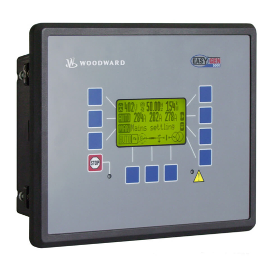
-
Contents
-
Table of Contents
-
Bookmarks
Quick Links
37427
easYgen-2000 Series
Genset Control
Configuration
Software Version 1.xxxx
Manual 37427
Related Manuals for Woodward easYgen-2000
Summary of Contents for Woodward easYgen-2000
-
Page 1
37427 easYgen-2000 Series Genset Control Configuration Software Version 1.xxxx Manual 37427… -
Page 2
Provides other helpful information that does not fall under the warning or caution categories. Woodward reserves the right to update any portion of this publication at any time. Information provided by Woodward is believed to be correct and reliable. However, Woodward assumes no responsibility unless otherwise expressly undertaken. -
Page 3: Table Of Contents
Manual 37427 easYgen-2000 Series — Genset Control Revision History Rev. Date Editor Changes NEW 09-06-09 Release Content 1. G ………………11 HAPTER ENERAL NFORMATION Document Overview ……………………..Abbreviations ……………………….12 2. C ………………..13 HAPTER ONFIGURATION Configuration Via The Front Panel ………………….
-
Page 4
Manual 37427 easYgen-2000 Series — Genset Control Configure Monitoring ……………………..47 Configure Monitoring: Generator ………………..47 Configure Monitoring: Generator, Operating Voltage / Frequency …………48 Configure Monitoring: Generator, Overfrequency (Levels 1 & 2) ANSI# 81O ………. 49 Configure Monitoring: Generator, Underfrequency (Levels 1 & 2) ANSI# 81U ……..51 Configure Monitoring: Generator, Overvoltage (Levels 1 &… -
Page 5
Manual 37427 easYgen-2000 Series — Genset Control Configure Application: Configure Inputs and Outputs …………..156 Configure Analog Inputs (FlexIn) ………………….156 Configure Discrete Inputs ……………………166 Configure External Discrete Inputs ………………….169 Discrete Outputs (LogicsManager) ………………….170 External Discrete Outputs (LogicsManager) ………………. 171 Configure Analog Outputs …………………… -
Page 6
Manual 37427 easYgen-2000 Series — Genset Control ………………. 271 PPENDIX OGICS ANAGER Structure and Description of the LogicsManager ………………. Configuration of the Command Chain ………………..272 Logical Symbols ……………………… 272 Logical Outputs ………………………. 273 Logical Outputs: Internal Flags ………………..273 Logical Outputs: Internal Functions ……………….. -
Page 7
Manual 37427 easYgen-2000 Series — Genset Control D. E ………………..318 PPENDIX VENT ISTORY Resetting the Event History ………………….Resetting the Event History Using the Front Panel …………….318 Event List …………………………318 Alarm List …………………………. 318 E. T …………… 321… -
Page 8
Manual 37427 easYgen-2000 Series — Genset Control Figures and Tables Figures Figure 2-1: ToolKit — Options window ……………………….. 15 Figure 2-2: ToolKit — visualization screen ……………………..19 Figure 2-3: ToolKit — analog value trending screen ……………………19 Figure 2-4: ToolKit — configuration screen ……………………..20 Figure 3-1: Code level display ………………………… -
Page 9
Manual 37427 easYgen-2000 Series — Genset Control Tables Table 1-1: Manual — overview …………………………11 Table 3-1: Configuration — standard values — configure language/clock ………………26 Table 3-2: Daylight saving time — configuration example ………………….29 Table 3-3: Daylight saving time — examplary dates ……………………29 Table 3-4: Configuration — standard values — enter password ……………….. -
Page 10
Manual 37427 easYgen-2000 Series — Genset Control Table 3-65: Application — standard values — configure breakers ………………..138 Table 3-66: Application — standard values — configure GCB ………………..149 Table 3-67: Application — standard values — configure MCB ………………..153 Table 3-68: Application — standard values — configure synchronization ……………… -
Page 11: Chapter 1. General Information
Manual 37427 easYgen-2000 Series — Genset Control Chapter 1. General Information Document Overview ≡≡≡≡≡≡≡≡≡≡≡≡≡≡≡≡≡≡≡≡≡≡≡≡≡ Type English German easYgen-2000 Series easYgen-2000 Series — Installation 37426 DE37426 easYgen-2000 Series — Configuration this manual 37427 DE37427 easYgen-2000 Series — Operation 37428 DE37428…
-
Page 12: Abbreviations
Manual 37427 easYgen-2000 Series — Genset Control Abbreviations ≡≡≡≡≡≡≡≡≡≡≡≡≡≡≡≡≡≡≡≡≡≡≡≡≡ The following abbreviations are frequently used throughout this and all other easYgen manuals: Circuit Breaker Code Level Current Transformer Counter-Clockwise Clockwise Discrete Input Discrete (Relay) Output Engine Control Unit Generator Circuit Breaker…
-
Page 13: Chapter 2. Configuration
Manual 37427 easYgen-2000 Series — Genset Control Chapter 2. Configuration Configuration Via The Front Panel ≡≡≡≡≡≡≡≡≡≡≡≡≡≡≡≡≡≡≡≡≡≡≡≡≡ Operation of the unit via the front panel is explained in the operation manual 37428. This manual will familiarize you with the unit, the meanings/functions of the buttons, and the display.
-
Page 14: Configuration Using The Pc
Install ToolKit Configuration and Visualization Software CAUTION Woodward’s ToolKit software (version 3.1 or higher) is required when configuring the unit via a PC. ToolKit from 3.1 If not already installed, download and install the ToolKit software. Please proceed as follows for this: •…
-
Page 15: Configure Toolkit
COM port and the default path for the configuration files. We recommend configuring a dedicated ToolKit data file directory (e.g. C:\Data\ToolKit) instead of storing the configuration files in the ToolKit installation directory (e.g. C:\Program Files\Woodward\ToolKit). The changes become effective after restarting ToolKit.
-
Page 16: Toolkit Files
When installing the *.SID and *.WTOOL files on a computer, it is recommended to create a dedicated ToolKit data file external to the ToolKit program. An example of this would be to create a Woodward ToolKit folder in a Data directory to store the *.SID and *.WTOOL files. The data files should be kept separate from the program files.
-
Page 17: Language-Dependent Sid Files
SID file for such an external device, which does not exist. A special *.sid file can be created in this case. Contact Woodward for support or create a *.sid file with the following content: <?xml version=»1.0″…
-
Page 18: Connect Toolkit And The Easygen Unit
NOTE A null modem serial cable must be used for communicating with the easYgen-2000 Series to ensure that the controller functions properly. The connection will not work if you are using a straight cable (a null modem cable has crosslinked transmit and receive lines in contrast to a straight serial cable).
-
Page 19: View Easygen Data With Toolkit
Manual 37427 easYgen-2000 Series — Genset Control View easYgen Data with ToolKit The following figure shows a visualization screen of ToolKit: Figure 2-2: ToolKit — visualization screen Navigation through the various visualization and configuration screens is performed by clicking on the icons, by selecting a navigation button, or by selecting a screen from the drop-down list to the right of the arrow icons.
-
Page 20: Configure The Easygen With Toolkit
Manual 37427 easYgen-2000 Series — Genset Control Configure the easYgen with ToolKit The following figure shows a configuration screen of ToolKit: Figure 2-4: ToolKit — configuration screen Entering a new value or selecting a value from a defined list will change the value in a field. The new value is written to the controller memory by changing to a new field or pressing the Enter key.
-
Page 21: Function Of The Inputs And Outputs
Manual 37427 easYgen-2000 Series — Genset Control Function of the Inputs and Outputs ≡≡≡≡≡≡≡≡≡≡≡≡≡≡≡≡≡≡≡≡≡≡≡≡≡≡≡≡≡≡≡≡ Discrete Inputs The discrete inputs may be grouped into two categories: programmable • The discrete input has been assigned a default function using either the LogicsManager or preconfigured alarms such as «emergency stop».
-
Page 22
Manual 37427 easYgen-2000 Series — Genset Control Reply MCB {2oc} programmable, pre-configured to discrete input [DI 7], terminals 43/50 Note: Negative logic function! The controller utilizes the CB auxiliary (B) contacts into this discrete input to reflect the state of the MCB. -
Page 23
Manual 37427 easYgen-2000 Series — Genset Control Discrete Outputs The discrete outputs can be grouped into two categories: programmable • The discrete output has been assigned a default function using the LogicsManager. The following text describes how these functions are assigned using the LogicsManager. It is possible to change the function of the discrete output if required. -
Page 24
Manual 37427 easYgen-2000 Series — Genset Control Command: close GCB {1oc} or {2oc} fixed to relay [R6], terminals 41/42 The «Command: close GCB» output issues the signal for the GCB to close. This relay may be configured as an impulse or constant output signal depending on parameter 3414 on page 150. -
Page 25: Chapter 3. Parameters
Manual 37427 easYgen-2000 Series — Genset Control Chapter 3. Parameters All parameters are assigned a unique Parameter Identification Number. The Parameter Identification Number may be used to reference individual parameters listed in this manual. This Parameter Identification Number is also displayed in the ToolKit configuration screens next to the respective parameter.
-
Page 26: Configure Language / Clock
Manual 37427 easYgen-2000 Series — Genset Control Configure Language / Clock ≡≡≡≡≡≡≡≡≡≡≡≡≡≡≡≡≡ The following parameters are used to set the unit language, the current date and time, and the daylight saving time feature. Parameter Table Level Text Setting range Default value…
-
Page 27
Manual 37427 easYgen-2000 Series — Genset Control Adjust clock: second 0 to 59 s Second Sekunden The second of the clock time is set here. Example: {1o} {1oc} {2oc} 0….0 second of the minute. 1708 59 …. -
Page 28
Manual 37427 easYgen-2000 Series — Genset Control Adjust clock: DST begin weekday weekday DST begin weekday Sommerzeitbeginn Wochentag The weekday for the DST begin date is configured here {1o} {1oc} {2oc} 4598 weekday order no. Adjust clock: DST begin n weekday DST begin nth. -
Page 29: Configure Display
Manual 37427 easYgen-2000 Series — Genset Control Adjust clock: DST end month 1 to 12 DST end month Sommerzeitende Monat The month for the DST end date is configured here. Example: {1o} {1oc} {2oc} 1….1 month of the year.
-
Page 30: Enter Password
Enter Password ≡≡≡≡≡≡≡≡≡≡≡≡≡≡≡≡≡ The easYgen-2000 Series utilizes a password protected multi-level configuration access hierarchy. This permits varying degrees of access to the parameters being granted by assigning unique passwords to designated personnel. A distinction is made between the access levels as follows:…
-
Page 31: Figure 3-1: Code Level Display
Manual 37427 easYgen-2000 Series — Genset Control Figure 3-1 shows a configuration menu screen in code level CL0 (left) and CL1 (right). Figure 3-1: Code level display Password: Entry via front panel 0000 to 9999 Password display Passwort Display The password for configuring the control via the front panel must be entered here.
-
Page 32: System Management
Manual 37427 easYgen-2000 Series — Genset Control System Management ≡≡≡≡≡≡≡≡≡≡≡≡≡≡≡≡≡ Parameter Table Level Text Setting range Default value System managment Device number 1 to 32 Configure display backlight On / Key activate. Key activate. Time until backlight shutdown 1 to 999 min…
-
Page 33
Manual 37427 easYgen-2000 Series — Genset Control NOTE The following parameters will only be displayed, if Factory Settings (parameter 1703) has been configured to Yes and the enter button has been pressed. Factory settings: Set default values Yes / No… -
Page 34: System Management: Password System
Manual 37427 easYgen-2000 Series — Genset Control System Management: Password System Parameter Table Level Text Setting range Default value Password system Basic code level 0 to 9999 Commissioning code level 0 to 9999 Temp. commissioning code level 0 to 9999 Temp.
-
Page 35: Configuration
Manual 37427 easYgen-2000 Series — Genset Control Configuration ≡≡≡≡≡≡≡≡≡≡≡≡≡≡≡≡≡≡≡≡≡≡≡≡≡ The configuration screen is accessed pressing the Configuration softkey on the Parameter screen. The following sub-menus are available to configure the unit: • Configure Measurement • Configure Monitoring • Configure Application •…
-
Page 36: Configure Measurement
Manual 37427 easYgen-2000 Series — Genset Control Configure Measurement ≡≡≡≡≡≡≡≡≡≡≡≡≡≡≡≡≡≡≡≡≡≡≡≡≡ Parameter Table Level Text Setting range Default value Configure measurement Show mains data Yes / No Generator type Synchron / Asynchron Synchron System rated frequency 50 / 60 Hz 50 Hz…
-
Page 37: Figure 3-2: Configure Measurement — Generator Type Selection
Manual 37427 easYgen-2000 Series — Genset Control Generator type Synchron / Asynchron Generator type Generatortyp The easYgen supports two types of generators: {1o} {1oc} {2oc} • synchron generators • asynchron generators (induction generators) Synchron: The unit provides all functions which are needed for synchron generator applications.
-
Page 38
Manual 37427 easYgen-2000 Series — Genset Control Generator rated voltage 50 to 650000 V Generator rated voltage Nennspannung Generator This value refers to the rated voltage of the generator (generator voltage {1o} {1oc} {2oc} on data plate) and is the voltage measured on the potential transformer 1766 primary. -
Page 39: Figure 3-3: Ac Power Triangle
Manual 37427 easYgen-2000 Series — Genset Control Mains rated reactive power 0.5 to 99999.9 kvar Mains rated react. pwr. [kvar] Nennblindleistung Netz [kvar] This value specifies the mains reactive power rating, which is used as a reference {1o} {1oc} {2oc} …
-
Page 40
Manual 37427 easYgen-2000 Series — Genset Control Measurement principle: Generator 3Ph 4W / 3Ph 3W / 1Ph 2W / 1Ph 3W Generator voltage measuring Gen.Spannungsmessung Please refer to the comments on measuring principles in the installation {1o} {1oc} {2oc} … -
Page 41
Manual 37427 easYgen-2000 Series — Genset Control Measurement principle: Mains 3Ph 4W / 3Ph 3W / 1Ph 2W / 1Ph 3W Mains voltage measuring Netz.Spannungsmessung Please refer to the comments on measuring principles in the installation {1o} {1oc} {2oc} … -
Page 42: Configure Measurement: Configure Transformer
Manual 37427 easYgen-2000 Series — Genset Control Configure Measurement: Configure Transformer Parameter Table Level Text Setting range Default value Configure transformer Gen. PT primary rated voltage 50 to 650000 V 400 V Gen. PT secondary rated volt. 50 to 480 V 400 V Gen.
-
Page 43
Manual 37427 easYgen-2000 Series — Genset Control Generator current transformer primary rating 1 to 32000/5 A Gen. CT primary rated current Generator Stromwandler This screen only applies to controls equipped with 5 A CT inputs. This will {1o} {1oc} {2oc} … -
Page 44: Busbar
Manual 37427 easYgen-2000 Series — Genset Control Busbar Busbar 1 potential transformer primary voltage rating 50 to 650000 V Busb1 PT primary rated voltage Sams. 1 Spg.Wandler primär Some applications may require the use of potential transformers to facilitate {1o}…
-
Page 45: Mains Pt
Manual 37427 easYgen-2000 Series — Genset Control Mains PT Mains potential transformer primary voltage rating 50 to 650000 V Mains PT primary rated voltage Netz.Spg.Wandler primär Some applications may require the use of potential transformers to facilitate {1o} {1oc} {2oc} …
-
Page 46: Ground Current Transformer
Manual 37427 easYgen-2000 Series — Genset Control Ground Current Transformer Ground current transformer primary rating 1 to 32000/5 A Gnd. CT primary rated current Erd-Stromwandler This screen only applies to controls equipped with 5 A CT inputs. This {1o}…
-
Page 47: Configure Monitoring
Manual 37427 easYgen-2000 Series — Genset Control Configure Monitoring ≡≡≡≡≡≡≡≡≡≡≡≡≡≡≡≡≡≡≡≡≡≡≡≡≡ Configure Monitoring: Generator Parameter Table Level Text Setting range Default value Configure generator monitoring Generator voltage monitoring Phase — phase / Phase — neutral Phase — phase Table 3-9: Monitoring — standard values — configure generator monitoring…
-
Page 48: Configure Monitoring: Generator, Operating Voltage / Frequency
Manual 37427 easYgen-2000 Series — Genset Control Configure Monitoring: Generator, Operating Voltage / Frequency Parameter Table Level Text Setting range Default value Configure generator operating voltage / frequency Upper voltage limit 100 to 150 % 110 % Lower voltage limit…
-
Page 49: Configure Monitoring: Generator, Overfrequency (Levels 1 & 2) Ansi# 81O
Manual 37427 easYgen-2000 Series — Genset Control Configure Monitoring: Generator, Overfrequency (Levels 1 & 2) ANSI# 81O This controller provides the user with two alarm levels for generator overfrequency. Both alarms are definite time alarms and are illustrated in the figure below. The figure diagrams a frequency trend and the associated pickup times and length of the alarms.
-
Page 50
Manual 37427 easYgen-2000 Series — Genset Control Gen. overfrequency: Self acknowledgment (Level 1/Level 2) Yes / No Self acknowledge Selbstquittierend Yes ….The control automatically clears the alarm if the fault condition is {1o} {1oc} {2oc} … -
Page 51: Configure Monitoring: Generator, Underfrequency (Levels 1 & 2) Ansi# 81U
Manual 37427 easYgen-2000 Series — Genset Control Configure Monitoring: Generator, Underfrequency (Levels 1 & 2) ANSI# 81U This controller provides the user with two alarm levels for generator underfrequency. Both alarms are definite time alarms and are illustrated in the figure below. The figure diagrams a frequency trend and the associated pickup times and length of the alarms.
-
Page 52
Manual 37427 easYgen-2000 Series — Genset Control Gen. underfrequency: Self acknowledgment (Level 1/Level 2) Yes / No Self acknowledge Selbstquittierend Yes….The control automatically clears the alarm if the fault condition is {1o} {1oc} {2oc} no longer detected. -
Page 53: Configure Monitoring: Generator, Overvoltage (Levels 1 & 2) Ansi# 59
Manual 37427 easYgen-2000 Series — Genset Control Configure Monitoring: Generator, Overvoltage (Levels 1 & 2) ANSI# 59 Voltage is monitored according to how the parameter «Generator voltage measuring» (parameter 1851 on page 40) is configured. This controller provides the user with two alarm levels for generator overvoltage. Both alarms are definite time alarms and are illustrated in the figure below.
-
Page 54
Manual 37427 easYgen-2000 Series — Genset Control Gen. overvoltage: Self acknowledgment (Level 1/Level 2) Yes / No Self acknowledge Selbstquittierend Yes ….The control automatically clears the alarm if the fault condition is {1o} {1oc} {2oc} … -
Page 55: Configure Monitoring: Generator, Undervoltage (Levels 1 & 2) Ansi# 27
Manual 37427 easYgen-2000 Series — Genset Control Configure Monitoring: Generator, Undervoltage (Levels 1 & 2) ANSI# 27 Voltage is monitored according to how the parameter «Generator voltage measuring» (parameter 1851 on page 40) is configured. This controller provides the user with two alarm levels for generator overvoltage. Both alarms are definite time alarms and are illustrated in the figure below.
-
Page 56
Manual 37427 easYgen-2000 Series — Genset Control Gen. undervoltage: Alarm class (Level 1/Level 2) Class A/B/C/D/E/F Alarm class Alarmklasse See chapter «Alarm» on page 269. {1o} {1oc} {2oc} 2051 2057 Each limit may be assigned an independent alarm class that specifies what action should be taken when the limit is surpassed. -
Page 57: Configure Monitoring: Generator, Time-Overcurrent Monit. (Levels 1, 2 & 3) Ansi# 50/51
Manual 37427 easYgen-2000 Series — Genset Control Configure Monitoring: Generator, Time-Overcurrent Monit. (Levels 1, 2 & 3) ANSI# 50/51 Current is monitored according to how the parameter «Generator current measuring» (parameter 1850 on page 40) is configured. This controller provides the user with three definite time alarm levels for generator overcurrent faults and may be setup as illustrated in the figure below.
-
Page 58
Manual 37427 easYgen-2000 Series — Genset Control Gen. overcurrent, TOC: Alarm class (Level 1/Level 2/Level 3) Class A/B/C/D/E/F Alarm class Alarmklasse See chapter «Alarm» on page 269. {1o} {1oc} {2oc} 2201 2207 Each limit may be assigned an independent alarm class that specifies what action 2213 should be taken when the limit is surpassed. -
Page 59: Configure Monitoring: Generator, Reverse/Reduced Power (Levels 1 & 2) Ansi# 32R/F
Manual 37427 easYgen-2000 Series — Genset Control Configure Monitoring: Generator, Reverse/Reduced Power (Levels 1 & 2) ANSI# 32R/F The power produced by the generator is calculated from the voltage and current values measured in accordance with how parameters «Generator voltage measuring» (parameter 1851 on page 40) and «Generator current measuring»…
-
Page 60
Manual 37427 easYgen-2000 Series — Genset Control Gen. reverse/reduced power: Monitoring (Level 1/Level 2) On / Off Monitoring Überwachung On….Reverse/reduced power monitoring is carried out according to the {1o} {1oc} {2oc} following parameters. Both values may be configured independent… -
Page 61: Configure Monitoring: Generator, Overload Iop (Levels 1 & 2) Ansi# 32
Manual 37427 easYgen-2000 Series — Genset Control Configure Monitoring: Generator, Overload IOP (Levels 1 & 2) ANSI# 32 (IOP = Isolated Operation in Parallel) The power produced by the generator is calculated from the voltage and current values measured inaccordance with how parameters «Generator voltage measuring»…
-
Page 62
Manual 37427 easYgen-2000 Series — Genset Control Gen. overload IOP: Self acknowledgment (Level 1/Level 2) Yes / No Self acknowledge Selbstquittierend Yes ….The control automatically clears the alarm if the fault condition is no {1o} {1oc} {2oc} … -
Page 63: Configure Monitoring: Generator, Overload Mop (Levels 1 & 2) Ansi# 32
Manual 37427 easYgen-2000 Series — Genset Control Configure Monitoring: Generator, Overload MOP (Levels 1 & 2) ANSI# 32 (MOP = Mains Parallel Operation) The power produced by the generator is calculated from the voltage and current values measured inaccordance with how parameters «Generator voltage measuring» (parameter 1851 on page 40) and «Generator current measuring»…
-
Page 64
Manual 37427 easYgen-2000 Series — Genset Control Gen. overload MOP: Self acknowledgment (Level 1/Level 2) Yes / No Self acknowledge Selbstquittierend Yes ….The control automatically clears the alarm if the fault condition is no {1o} {1oc} {2oc} … -
Page 65: Configure Monitoring: Generator, Unbalanced Load (Levels 1 & 2) Ansi# 46
Manual 37427 easYgen-2000 Series — Genset Control Configure Monitoring: Generator, Unbalanced Load (Levels 1 & 2) ANSI# 46 Unbalanced load is monitored according to how the parameters «Generator voltage measuring» (parameter 1851 on page 40) and «Generator current measuring» (parameter 1850 on page 40) are configured. The unbalanced load alarm monitors the individual phase currents of the generator.
-
Page 66
Manual 37427 easYgen-2000 Series — Genset Control Formulas for calculation Phase L1 Phase L2 Phase L3 × × × × × × Exceeding ≥ ≥ ≥ − × × − × × − × × Falling below ≤ ≤ ≤… -
Page 67
Manual 37427 easYgen-2000 Series — Genset Control Parameters Gen. unbalanced load: Monitoring (Level 1/Level 2) On / Off Monitoring Überwachung On ….Unbalanced load monitoring is carried out according to the {1o} {1oc} {2oc} following parameters. Monitoring is performed at two levels. Both… -
Page 68: Configure Monitoring: Generator, Voltage Asymmetry
Manual 37427 easYgen-2000 Series — Genset Control Configure Monitoring: Generator, Voltage Asymmetry The voltage asymetry alarm monitors the individual three-phase voltages of the generator. Voltage asymmetry monitoring is always performed phase-phase (delta). The percentage threshold value is the permissible variation from the average measured voltage of all three phases.
-
Page 69
Manual 37427 easYgen-2000 Series — Genset Control Gen. voltage asymmetry: Self acknowledgment Yes / No Self acknowledge Selbstquittierend Yes ….The control automatically clears the alarm if the fault condition is {1o} {1oc} {2oc} no longer detected. -
Page 70: Configure Monitoring: Generator, Ground Fault (Levels 1 & 2)
Manual 37427 easYgen-2000 Series — Genset Control Configure Monitoring: Generator, Ground Fault (Levels 1 & 2) Mains Current Input is Configured for Mains Current (Calculated Ground Fault) (Refer to parameter 1854 on page 41) The current produced by the generator is monitored depending on how parameter «Generator current measuring»…
-
Page 71: Figure 3-5: Monitoring — Calculated Generator Ground Current — Vector Diagram
Manual 37427 easYgen-2000 Series — Genset Control Calculation a) No ground fault b) Ground fault (with vectorial calculation) c) Ground fault (I = ground fault current) Figure 3-5: Monitoring — calculated generator ground current — vector diagram ground current I is calculated geometrically/vectorially.
-
Page 72
Manual 37427 easYgen-2000 Series — Genset Control Parameter Gen. ground fault: Monitoring (Level 1/Level 2) On / Off Monitoring Überwachung On….Ground current monitoring is carried out according to the following {1o} {1oc} {2oc} parameters. Monitoring is performed at two levels. Both values may… -
Page 73: Configure Monitoring: Generator, Phase Rotation
Manual 37427 easYgen-2000 Series — Genset Control Configure Monitoring: Generator, Phase Rotation CAUTION Ensure that the control unit is properly connected to phase voltages on both sides of the circuit breaker(s) during installation. Failure to do so may result in damage to the control unit and/or generation equipment due to the breaker closing asynchronously or with mismatched phase rotations.
-
Page 74
Manual 37427 easYgen-2000 Series — Genset Control Gen.voltage phase rotation: Monitoring On / Off Monitoring Überwachung On….Phase rotation monitoring is carried out according to the following {1o} {1oc} {2oc} parameters. 3950 Off ….No monitoring is carried out. -
Page 75: Configure Monitoring: Generator, Inverse Time-Overcurrent Monitoring Ansi# Iec 255
Manual 37427 easYgen-2000 Series — Genset Control Configure Monitoring: Generator, Inverse Time-Overcurrent Monitoring ANSI# IEC 255 The current produced by the generator is monitored depending on how parameter «Generator current measuring» (parameter 1850 on page 40) is configured. If an overcurrent condition is detected, the fault recognition time is determined by the configured tripping characteristic curve and the measured current.
-
Page 76: Figure 3-7: Monitoring — Generator Inverse Time-Overcurrent — «Highly Inverse» Characteristic
Manual 37427 easYgen-2000 Series — Genset Control Highly inverse Ip = In; I-Start = 1.1 x In t[s] 1000 tp = 1.6 s tp = 1.0 s tp = 0.5 s tp = 0.2 s tp = 0.1 s tp = 0.05 s I-Start/Ip 0.01…
-
Page 77: Table 3-23: Monitoring — Standard Values — Generator Inverse Time-Overcurrent
Manual 37427 easYgen-2000 Series — Genset Control Parameter table Level Text Setting range Default value Inverse time-overcurrent (the hysteresis is 1 % of the rated value) Monitoring On / Off Inverse time characteristic Normal / High / Extreme Normal Inverse time overcurrent Tp 0.01 to 1.99 s…
-
Page 78
Manual 37427 easYgen-2000 Series — Genset Control Gen. overcurrent, inverse: Alarm class Class A/B/C/D/E/F Alarm class Alarmklasse See chapter «Alarm» on page 269. {1o} {1oc} {2oc} 4031 Each limit may be assigned an independent alarm class that specifies what action should be taken when the limit is surpassed. -
Page 79: Configure Monitoring: Generator, Lagging Power Factor Monitoring (Levels 1 & 2)
Manual 37427 easYgen-2000 Series — Genset Control Configure Monitoring: Generator, Lagging Power Factor Monitoring (Levels 1 & 2) The power factor is monitored for becoming more lagging (i.e. inductive) than an adjustable limit. This limit may be a lagging or leading power factor limit. There are two lagging power factor alarm levels available in the control.
-
Page 80
Manual 37427 easYgen-2000 Series — Genset Control Gen. lagging power factor: Monitoring (Level 1/Level 2) On / Off Monitoring Überwachung On….Generator lagging power factor monitoring is carried out according {1o} {1oc} {2oc} to the following parameters. Monitoring is performed at two levels. -
Page 81: Configure Monitoring: Generator, Leading Power Factor Monitoring (Levels 1 & 2)
Manual 37427 easYgen-2000 Series — Genset Control Configure Monitoring: Generator, Leading Power Factor Monitoring (Levels 1 & 2) The power factor is monitored for becoming more leading (i.e. capacitive) than an adjustable limit. This limit may be a leading or lagging power factor limit. There are two leading power factor alarm levels available in the control.
-
Page 82
Manual 37427 easYgen-2000 Series — Genset Control Gen. leading power factor: Monitoring (Level 1/Level 2) On / Off Monitoring Überwachung On ….Generator leading power factor monitoring is carried out according {1o} {1oc} {2oc} to the following parameters. Monitoring is performed at two levels. -
Page 83: Configure Monitoring: Mains
Manual 37427 easYgen-2000 Series — Genset Control Configure Monitoring: Mains Parameter Table Level Text Setting range Default value Configure mains monitoring Mains voltage monitoring Phase — phase / Phase — neutral Phase — phase Mains settling time 0 to 9999 s…
-
Page 84
Manual 37427 easYgen-2000 Series — Genset Control Operating voltage window, mains, maximum limit hysteresis 0 to 50 % Hysteresis upper voltage limit Hyst. obere Spannungsabw. If the mains voltage has exceeded the limit configured in parameter 5810, the {1o} {1oc} {2oc} … -
Page 85: Configure Monitoring: Mains, Decoupling
Manual 37427 easYgen-2000 Series — Genset Control Configure Monitoring: Mains, Decoupling The mains decoupling function is intended for use in a mains parallel operation and monitors a series of subordinate mains protection thresholds. If a threshold is exceeded, the easYgen initiates a breaker opening and separates the generator(s) from the mains at the defined breaker.
-
Page 86
Manual 37427 easYgen-2000 Series — Genset Control Mains decoupling: Alarm class Class A/B/C/D/E/F Alarm class Alarmklasse See chapter «Alarm» on page 269. {1o} {1oc} {2oc} 3111 Each limit may be assigned an independent alarm class that specifies what action should be taken when the limit is surpassed. -
Page 87: Configure Monitoring: Mains, Overfrequency (Levels 1 & 2) Ansi# 81O
Manual 37427 easYgen-2000 Series — Genset Control Configure Monitoring: Mains, Overfrequency (Levels 1 & 2) ANSI# 81O There are two overfrequency alarm levels available in the control. Both alarms are definite time alarms and are illustrated in the figure below. The figure diagrams a frequency trend and the associated pickup times and length of the alarms.
-
Page 88
Manual 37427 easYgen-2000 Series — Genset Control Mains overfrequency: Self acknowledgment (Limit 1/Limit 2) Yes / No Self acknowledge Selbstquittierend Yes ….The control automatically clears the alarm if the fault condition is {1o} {1oc} {2oc} … -
Page 89: Configure Monitoring: Mains, Underfrequency (Levels 1 & 2) Ansi# 81U
Manual 37427 easYgen-2000 Series — Genset Control Configure Monitoring: Mains, Underfrequency (Levels 1 & 2) ANSI# 81U There are two underfrequency alarm levels available in the control. Both alarms are definite time alarms and are illustrated in the figure below. The figure diagrams a frequency trend and the associated pickup times and length of the alarms.
-
Page 90
Manual 37427 easYgen-2000 Series — Genset Control Mains underfrequency: Self acknowledgment (Level 1/Level 2) Yes / No Self acknowledge Selbstquittierend Yes ….The control automatically clears the alarm if the fault condition is {1o} {1oc} {2oc} … -
Page 91: Configure Monitoring: Mains, Overvoltage (Levels 1 & 2) Ansi# 59
Manual 37427 easYgen-2000 Series — Genset Control Configure Monitoring: Mains, Overvoltage (Levels 1 & 2) ANSI# 59 Voltage is monitored depending on parameter «Mains voltage measuring» (parameter 1853 on page 41). There are two overvoltage alarm levels available in the control. Both alarms are definite time alarms and are illustrated in the figure below.
-
Page 92
Manual 37427 easYgen-2000 Series — Genset Control Mains overvoltage: Self acknowledgment (Level 1/Level 2) Yes / No Self acknowledge Selbstquittierend Yes ….The control automatically clears the alarm if the fault condition is {1o} {1oc} {2oc} … -
Page 93: Configure Monitoring: Mains, Undervoltage (Levels 1 & 2) Ansi# 27
Manual 37427 easYgen-2000 Series — Genset Control Configure Monitoring: Mains, Undervoltage (Levels 1 & 2) ANSI# 27 Voltage is monitored depending on parameter «Mains voltage measuring» (parameter 1853 on page 41). There are two undervoltage alarm levels available in the control. Both alarms are definite time alarms and are illustrated in the figure below.
-
Page 94
Manual 37427 easYgen-2000 Series — Genset Control Mains undervoltage: Self acknowledgment (Level 1/Level 2) Yes / No Self acknowledge Selbstquittierend Yes ….The control automatically clears the alarm if the fault condition is {1o} {1oc} {2oc} … -
Page 95: Configure Monitoring: Mains, Phase Shift
Manual 37427 easYgen-2000 Series — Genset Control Configure Monitoring: Mains, Phase Shift A vector/phase shift is defined as the sudden variation of the voltage curve which may be caused by a major generator load change. It usually occurs, if the utility opens the MCB, which causes a load change for the genset.
-
Page 96
Manual 37427 easYgen-2000 Series — Genset Control Mains phase shift: Monitoring On / Off Monitoring Überwachung On ….Phase shift monitoring is carried out according to the following {1o} {1oc} {2oc} parameters. 3050 Off ….Monitoring is disabled. -
Page 97
Manual 37427 easYgen-2000 Series — Genset Control Mains phase shift: Self acknowledgment Yes / No Self acknowledge Selbstquittierend Yes ….The control automatically clears the alarm if the fault condition is {1o} {1oc} {2oc} no longer detected. -
Page 98: Configure Monitoring: Mains, Voltage Phase Rotation — {2Oc
Manual 37427 easYgen-2000 Series — Genset Control Configure Monitoring: Mains, Voltage Phase Rotation — {2oc} CAUTION Please ensure during installation that all voltages applied to this unit are wired correctly to both sides of the circuit breaker. Failure to do so may result in damage to the control unit and/or generation…
-
Page 99
Manual 37427 easYgen-2000 Series — Genset Control Mains voltage phase rotation: Monitoring On / Off Monitoring Überwachung On ….Phase rotation monitoring is carried out according to the following {1o} {1oc} {2oc} parameters 3970 Off ….No monitoring is carried out. -
Page 100: Configure Monitoring: Engine
Manual 37427 easYgen-2000 Series — Genset Control Configure Monitoring: Engine Configure Monitoring: Engine, Overspeed (Levels 1 & 2) ANSI# 12 The speed measured by the magnetic pickup unit (MPU) is monitored for overspeed. If the MPU is disabled, the speed may only be monitored using the generator overfrequency monitoring. If the MPU speed exceeds the overspeed limits the configured alarms will be initiated.
-
Page 101
Manual 37427 easYgen-2000 Series — Genset Control Engine overspeed: Self acknowledgment (Level 1/Level 2) Yes / No Self acknowledge Selbstquittierend Yes ….The control automatically clears the alarm if the fault condition is {1o} {1oc} {2oc} … -
Page 102: Configure Monitoring: Engine, Underspeed (Levels 1 & 2)
Manual 37427 easYgen-2000 Series — Genset Control Configure Monitoring: Engine, Underspeed (Levels 1 & 2) The speed measured by the magnetic pickup unit (MPU) is monitored for underspeed. If the MPU is disabled, the speed may only be monitored using the generator underfrequency monitoring. If the MPU speed falls below the underspeed limits the configured alarms will be initiated.
-
Page 103
Manual 37427 easYgen-2000 Series — Genset Control Engine underspeed: Self acknowledgment (Level 1/Level 2) Yes / No Self acknowledge Selbstquittierend Yes ….The control automatically clears the alarm if the fault condition is {1o} {1oc} {2oc} … -
Page 104: Configure Monitoring: Engine/Generator, Speed Detection (Speed/Frequency Mismatch)
Manual 37427 easYgen-2000 Series — Genset Control Configure Monitoring: Engine/Generator, Speed Detection (Speed/Frequency Mismatch) Speed detection checks if the generator voltage frequency f (determined from the measured generator voltage) differs from the measured engine speed n (determined from the Pickup signal) and determines a difference (Δf-n).
-
Page 105: Table 3-37: Monitoring — Standard Values — Plausibility Control N/F
Manual 37427 easYgen-2000 Series — Genset Control Parameter table Level Text Setting range Default value Speed detection (speed/frequency mismatch) (the hysteresis is 50 RPM). Monitoring On / Off Speed/frequency mismatch limit 1.5 to 8.5 Hz 5.0 Hz Delay 0.02 to 99.99 s 2.00 s…
-
Page 106: Configure Monitoring: Engine, Generator Active Power Mismatch
Manual 37427 easYgen-2000 Series — Genset Control Configure Monitoring: Engine, Generator Active Power Mismatch If enabled, this monitoring function becomes only active if generator power control is enabled (refer to Configure Application: Controller, Load Control on page 223 for more information). If the measured generator power deviates from the power set point by a value exceeding the limit configured in parameter 2925 for a time exceeding the delay configured in parameter 2923, an alarm will be issued.
-
Page 107: Configure Monitoring: Engine, Mains Active Power Mismatch
Manual 37427 easYgen-2000 Series — Genset Control Configure Monitoring: Engine, Mains Active Power Mismatch If enabled, this monitoring function becomes only active if generator power control is enabled and the active power set point is configured to «Import» or «Export» (refer to Configure Application: Controller, Load Control on page 223 for more information).
-
Page 108: Configure Monitoring: Engine, Generator Unloading Mismatch
Manual 37427 easYgen-2000 Series — Genset Control Configure Monitoring: Engine, Generator Unloading Mismatch This monitoring function is always enabled and becomes active when a stop command is issued. Following a stop command, the controller tries to reduce the power before opening the GCB. If the power falls below the unload limit (parameter 3125) before the delay (parameter 3123) expires, a «GCB open»…
-
Page 109: Configure Monitoring: Engine, Start Failure
Manual 37427 easYgen-2000 Series — Genset Control Configure Monitoring: Engine, Start Failure If it is not possible to start the engine within a configured number of start attempts (refer to Configure Application: Configure Engine, Start/Stop on page 182), an alarm will be initiated.
-
Page 110: Configure Monitoring: Engine, Shutdown Malfunction
Manual 37427 easYgen-2000 Series — Genset Control Configure Monitoring: Engine, Shutdown Malfunction If it is not possible to stop the engine within a configured time, an alarm will be initiated. If this protective function is triggered, the display indicates «Eng. stop malfunct.» and the logical command variable «05.06»…
-
Page 111: Configure Monitoring: Engine, Unintended Stop
Manual 37427 easYgen-2000 Series — Genset Control Configure Monitoring: Engine, Unintended Stop If an engine stop has been detected without a stop command being issued, an alarm will be initiated. If this protective function is triggered, the display indicates «Unintended stop» and the logical command variable «05.05»…
-
Page 112: Configure Monitoring: Engine, Operating Range Failure
Manual 37427 easYgen-2000 Series — Genset Control Configure Monitoring: Engine, Operating Range Failure The operating range failure monitoring issues an alarm if one of the following conditions is fulfilled: • Check 1: The easYgen tries to close the GCB, but the generator is not within its operating range (parameters 5800, 5801, 5802, or 5803 on page 48) •…
-
Page 113: Configure Monitoring: Engine, Charge Alternator (D+)
Manual 37427 easYgen-2000 Series — Genset Control Configure Monitoring: Engine, Charge Alternator (D+) The charge alternator monitoring issues an alarm if the voltage measured at the auxiliary excitation input D+ (terminal 52) falls below a fix limit. The fix limit depends on the power supply voltage. If a power supply voltage exceeding 16 V is detected, the unit assumes a 24 V system and uses a limit of 20 V.
-
Page 114: Configure Monitoring: Breaker Monitoring
Manual 37427 easYgen-2000 Series — Genset Control Configure Monitoring: Breaker Monitoring Configure GCB Circuit breaker monitoring contains two alarms: A breaker reclose alarm and a breaker open alarm. Reclose Alarm: If the control initiates a close of the breaker and the breaker fails to close after the configured number of attempts the monitoring CB alarm will be initiated (refer to parameter «GCB maximum closing…
-
Page 115: Configure Synchronization Gcb
Manual 37427 easYgen-2000 Series — Genset Control Configure Synchronization GCB Parameter table Level Text Setting range Default value Breaker monitoring — GCB synchronization Monitoring On / Off Timeout 3 to 999 s 60 s Alarm class A/B/C/D/E/F Self acknowledgment Yes / No…
-
Page 116: Configure Mcb {2Oc
Manual 37427 easYgen-2000 Series — Genset Control Configure MCB {2oc} NOTE If an alarm is detected when attempting to close the MCB, an emergency power operation will be carried out if the «Emergency start with MCB failure» is On. If an alarm class higher than ‘B’ class has been selected it will not be possible to start the engine with the setting «Emergency start with MCB failure»…
-
Page 117
Manual 37427 easYgen-2000 Series — Genset Control Circuit breaker monitoring MCB: Monitoring On / Off MCB monitoring NLS Überwachung On ….Monitoring of the MCB is carried out according to the following {1o} {1oc} {2oc} parameters. 2620 Off ….Monitoring is disabled. -
Page 118: Configure Synchronization Mcb
Manual 37427 easYgen-2000 Series — Genset Control Configure Synchronization MCB Parameter table Level Text Setting range Default value Breaker monitoring — MCB synchronization Monitoring On / Off Timeout 3 to 999 s 60 s Alarm class A/B/C/D/E/F Self acknowledgment Yes / No…
-
Page 119: Configure Monitoring: Breakers, Generator / Busbar / Mains Phase Rotation — {2Oc
Manual 37427 easYgen-2000 Series — Genset Control Configure Monitoring: Breakers, Generator / Busbar / Mains Phase Rotation — {2oc} Correct phase rotation of the phase voltages ensures that damage will not occur during a breaker closure to either the mains or the generator. The voltage phase rotation alarm checks, if the phase rotation of the measured voltage systems are identical.
-
Page 120: Configure Monitoring: Flexible Limits
Manual 37427 easYgen-2000 Series — Genset Control Configure Monitoring: Flexible Limits CAUTION Flexible Limits must not be used for protective functions, because the monitoring function is not guaranteed beyond an exceeding of 320 %. CAUTION It is not possible to monitor temperature values in Degree Fahrenheit and pressure values in psi. Even if the parameters 3631 or 3630 on page 156 are configured to a value display in °F or psi, flexible limit…
-
Page 121: Figure 3-13: Monitoring — Flexible Limits — Data Source Selection
Manual 37427 easYgen-2000 Series — Genset Control FlexLimit {x} [x = 1 to 16]: Description user-defined Description Beschreibung A description for the respective flexible limit may be entered here. The description {1o} {1oc} {2oc} may have 4 through 16 characters and is displayed instead of the default text if this 4208 limit is exceeded.
-
Page 122: Table 3-53: Monitoring — Flexible Limits — Analog Value Examples
Manual 37427 easYgen-2000 Series — Genset Control FlexLimit {x} [x = 1 to 16]: Threshold -32000 to 32000 Limit Grenzwert The threshold limit of the value to be monitored is defined by this parameter. If this {1o} {1oc} {2oc} …
-
Page 123: Table 3-54: Monitoring — Flexible Limits — Parameter Ids
Manual 37427 easYgen-2000 Series — Genset Control FlexLimit {x} [x = 1 to 16]: Self acknowledge Yes / No Self acknowledge Selbstquittierend Yes ….The control automatically clears the alarm if the fault condition is {1o} {1oc} {2oc} …
-
Page 124: Configure Monitoring: Miscellaneous
Manual 37427 easYgen-2000 Series — Genset Control Configure Monitoring: Miscellaneous Configure Monitoring: Miscellaneous, Alarm Acknowledgement Self acknowledgment of the centralized alarm (horn) 0 to 1,000 s Time until horn reset Zeit Hupenreset After each alarm of alarm class B through F occurs, the alarm LED flashes and the…
-
Page 125: Configure Monitoring: Miscellaneous, Configure Can Bus Overload
Manual 37427 easYgen-2000 Series — Genset Control Configure Monitoring: Miscellaneous, Configure CAN bus overload The CAN busses are monitored. If the sum of CAN bus messages on all CAN buses together exceeds 32 per 20 ms, an alarm will be initiated.
-
Page 126: Configure Monitoring: Miscellaneous, Configure Can Interface 1
Manual 37427 easYgen-2000 Series — Genset Control Configure Monitoring: Miscellaneous, Configure CAN Interface 1 The CANopen interface 1 is monitored. If the interface does not receive a Receive Process Data Object (RPDO) before the delay expires, an alarm will be initiated.
-
Page 127: Configure Monitoring: Miscellaneous, Configure Can Interface 2
Manual 37427 easYgen-2000 Series — Genset Control Configure Monitoring: Miscellaneous, Configure CAN Interface 2 The CANopen interface 2 is monitored. If the interface does not receive a message from the external expansion board (Node-ID) before the delay expires, an alarm will be initiated.
-
Page 128: Configure Monitoring: Miscellaneous, Configure Can Interface 2, J1939 Interface
Manual 37427 easYgen-2000 Series — Genset Control Configure Monitoring: Miscellaneous, Configure CAN Interface 2, J1939 Interface This watchdog triggers if the easYgen is configured to receive J1939 data from an ECU (parameter 15102) connected to the CAN bus to evaluate these data, and no data is received from the ECU.
-
Page 129: Table 3-59: Monitoring — Standard Values — J1939 Interface Red Stop Lamp
Manual 37427 easYgen-2000 Series — Genset Control Configure Monitoring: J1939 Interface, Configure CAN Interface 2, Red Stop Alarm This watchdogs monitors, whether a specific alarm bit is received from the CAN J1939 interface. This enables to configure the easYgen in a way that a reaction is caused by this bit (e.g. warning, shutdown).
-
Page 130: Table 3-60: Monitoring — Standard Values — J1939 Interface Amber Warning Lamp
Manual 37427 easYgen-2000 Series — Genset Control Configure Monitoring: J1939 Interface, Configure CAN Interface 2, Amber Warning Alarm This watchdogs monitors, whether a specific alarm bit is received from the CAN J1939 interface. This enables to configure the easYgen in a way that a reaction is caused by this bit (e.g. warning, shutdown).
-
Page 131: Configure Monitoring: Miscellaneous, Battery, Overvoltage (Levels 1 & 2)
Manual 37427 easYgen-2000 Series — Genset Control Configure Monitoring: Miscellaneous, Battery, Overvoltage (Levels 1 & 2) There are two battery overvoltage alarm levels available in the control. Both alarms are definite time alarms and are illustrated in the figure below. The figure diagrams a frequency trend and the associated pickup times and length of the alarms.
-
Page 132
Manual 37427 easYgen-2000 Series — Genset Control Battery overvoltage: Self acknowledgment (Level 1/Level 2) Yes / No Self acknowledge Selbstquittierend Yes….The control automatically clears the alarm if the fault condition is {1o} {1oc} {2oc} no longer detected. -
Page 133: Configure Monitoring: Miscellaneous, Battery, Undervoltage (Levels 1 & 2)
Manual 37427 easYgen-2000 Series — Genset Control Configure Monitoring: Miscellaneous, Battery, Undervoltage (Levels 1 & 2) There are two battery undervoltage alarm levels available in the control. Both alarms are definite time alarms and are illustrated in the figure below. The figure diagrams a frequency trend and the associated pickup times and length of the alarms.
-
Page 134
Manual 37427 easYgen-2000 Series — Genset Control Battery undervoltage: Self acknowledgment (Level 1/Level 2) Yes / No Self acknowledge Selbstquittierend Yes ….The control automatically clears the alarm if the fault condition is {1o} {1oc} {2oc} … -
Page 135: Configure Monitoring: Miscellaneous, Multi-Unit Parameter Alignment
Manual 37427 easYgen-2000 Series — Genset Control Configure Monitoring: Miscellaneous, Multi-Unit Parameter Alignment The multi-unit parameter alignment functionality requires that the relevant parameters are all configured identically at all participating units. If at least one of these parameters is configured different in at least one of the units, the display indicates «Parameter alignment»…
-
Page 136
Manual 37427 easYgen-2000 Series — Genset Control Multi-unit configuration check: Alarm class Class A/B/C/D/E/F Alarm class Alarmklasse See chapter «Alarm» on page 269. {1o} {1oc} {2oc} 4071 This function may be assigned an independent alarm class that specifies what action should be taken when this function triggers an alarm. -
Page 137: Configure Monitoring: Miscellaneous, Multi-Unit Missing Members
Manual 37427 easYgen-2000 Series — Genset Control Configure Monitoring: Miscellaneous, Multi-Unit Missing Members The multi-unit missing members monitoring function checks whether all participating units are available (sending data on the load share line). If the number of available units is less than the number of members configured in parameter 4063 for at least the delay time (refer to below note), the display indicates «Missing members»…
-
Page 138: Configure Application
Manual 37427 easYgen-2000 Series — Genset Control Configure Application ≡≡≡≡≡≡≡≡≡≡≡≡≡≡≡≡≡≡≡≡≡≡≡≡≡ Configure Application: Configure Breakers NOTE The assignment of the defined relays to defined functions occurs by selection of the application mode (i.e. function «Command: Close GCB» on relay [R 6], this relay can no longer be operated via the LogicsManager).
-
Page 139
Manual 37427 easYgen-2000 Series — Genset Control Application modes «None» / «GCB open» / «GCB» / «GCB/MCB» Application mode Betriebsmodus The unit may be configured for four different application modes. The discrete {1o} {1oc} {2oc} inputs and relay outputs are pre-defined dependent upon the selected application 3401 mode. -
Page 140: Operation Of The Circuit Breakers
Manual 37427 easYgen-2000 Series — Genset Control Operation Of The Circuit Breakers The configuration of pulse switching takes place in the following screen and has the described effect on the signal sequence (the MCB cannot be controlled by the continuous pulse for security reasons, because otherwise, the MCB would be opened in case of a failure/exchange of the easYgen).
-
Page 141
Manual 37427 easYgen-2000 Series — Genset Control Synchronization GCB/MCB {1oc} or {2oc} The synchronization is active, if the following conditions are met simultaneously. The display indicates «Synchronization GCB» or «Synchronization MCB». Automatic operation • The operating mode AUTOMATIC has been selected •… -
Page 142
Manual 37427 easYgen-2000 Series — Genset Control Manual operation • Operating mode MANUAL has been selected • The parameter «Dead busbar closure MCB» (parameter 3431 on page 154) is configured On • The mains voltage is available and within the configured operating range (refer to Configure Monitoring: Mains, Operating Voltage / Frequency on page 83) •… -
Page 143
Manual 37427 easYgen-2000 Series — Genset Control Transition Mode Breaker: Transition mode Parallel / Interchange / Closed T. / Open T. / External Breaker transition mode Schaltermodus The control unit automatically controls the two breakers (MCB and GCB). Up to… -
Page 144
Manual 37427 easYgen-2000 Series — Genset Control Breaker Logic «PARALLEL» Parallel operation is enabled by configuring parameter 3411 to «PARALLEL». NOTE Parallel breaker logic must be selected for the following operation modes: • Isolated operation • Mains parallel operation In the event of an engine start request the following occurs: •… -
Page 145
Manual 37427 easYgen-2000 Series — Genset Control Breaker Logic «INTERCHANGE» {2oc} Mains interchange (import/export) real power control is enabled by configuring parameter 3411 to «INTERCHANGE». NOTE For this breaker logic to function correctly, the mains power measurement must be connected properly. -
Page 146
Manual 37427 easYgen-2000 Series — Genset Control Breaker Logic «OPEN TRANSIT.» {2oc} Open transition (break-before-make/change over logic) is enabled via configuration of parameter 3411 to «OPEN TRANSITION». In the event of an engine start request, a change is made from mains to generator supply. The following occurs: •… -
Page 147
Manual 37427 easYgen-2000 Series — Genset Control Overview {2oc} STOP MANUAL AUTOMATIC EXTERNAL: Breaker logic «External» In a mains parallel operation, decoupling from the mains is carried out via the MCB or the GCB in the event of a mains failure. -
Page 148: Configure Application: Configure Breakers, Dead Bus Detection Limit
Manual 37427 easYgen-2000 Series — Genset Control Overview {2oc} (continued) STOP MANUAL AUTOMATIC INTERCHANGE: Breaker logic «Soft loading / interchange synchronization» The MCB and the GCB are synchronized, in order to avoid a dead busbar in this breaker logic mode. The operation of a breaker under load is avoided by utilizing the ability to soft load.
-
Page 149: Configure Application: Configure Breakers, Gcb
Manual 37427 easYgen-2000 Series — Genset Control Configure Application: Configure Breakers, GCB NOTE Normally Open Contacts (No): If a voltage is applied to the discrete input terminals, the discrete input is enabled (i.e. in the operating state). The controller only recognizes a fault condition or control operation via the discrete input when the discrete input terminals are energized.
-
Page 150
Manual 37427 easYgen-2000 Series — Genset Control Breaker: «Command: GCB close» Constant / Impulse GCB close command GLS Schließen-Befehl Impulse ..The relay «Command: GCB close» issues an add-on pulse. If the {1o} {1oc} {2oc} relay is configured in this manner a holding coil and sealing contacts 3414 must be installed externally to the control unit. -
Page 151
Manual 37427 easYgen-2000 Series — Genset Control Breaker: Max. permissible positive phase angle GCB 0.0 to 60.0 ° Max positive phase angle GCB Max. pos. Winkeldifferenz GLS This parameter is only displayed, if parameter 5729 is configured to {1o}… -
Page 152
Manual 37427 easYgen-2000 Series — Genset Control Breaker: Breaker unblocking GCB Yes / No GCB auto unlock GLS auto entriegeln This is used for special circuit breakers to put the breaker into a defined initial {1o} {1oc} {2oc} … -
Page 153: Configure Application: Configure Breakers, Mcb
Manual 37427 easYgen-2000 Series — Genset Control Configure Application: Configure Breakers, MCB Parameter table Level Text Setting range Default value Configure MCB MCB control (easYgen-2200) Off / 1 Relay 1 Relay MCB control (easYgen-2500) Off / 1 Relay / 2 Relays…
-
Page 154
Manual 37427 easYgen-2000 Series — Genset Control Breaker: Voltage differential MCB 0.50 to 20.00 % Voltage differential MCB Max. Spg. Differenz NLS This value refers to the mains rated voltage (parameter 1768 on page 38). {1o} {1oc} {2oc} … -
Page 155: Configure Application: Configure Breakers, Synchronization
Manual 37427 easYgen-2000 Series — Genset Control Breaker: Enable MCB LogicsManager Enable MCB Freigabe NLS Once the conditions of the LogicsManager have been fulfilled the MCB will be {1o} {1oc} {2oc} enabled. The LogicsManager and its default settings are explained on page 271 12923 in Appendix B: «LogicsManager».
-
Page 156: Configure Application: Configure Inputs And Outputs
Manual 37427 easYgen-2000 Series — Genset Control Configure Application: Configure Inputs and Outputs Configure Analog Inputs (FlexIn) Parameter table Level Text Setting range Default value Configure analog inputs Display temperature in °C / °F °C Display pressure in bar / psi…
-
Page 157: Table 3-70: Application — Standard Values — Configure Analog Input Table A / B
Manual 37427 easYgen-2000 Series — Genset Control NOTE The X and Y junction may be moved within the range of values (the junctions don’t have to be equidistant). When configuring the X coordinates, ensure the coordinates always increase in scale continuously. In…
-
Page 158: Table 3-71: Analog Inputs — Table Characteristics — Parameter Ids
Manual 37427 easYgen-2000 Series — Genset Control The following parameters are used to configure the characteristic curve. Refer to Table 3-71 for the parameter IDs of the individual parameters for all scaling points of tables A and B. Table {x} [x = A/B]: X-coordinate {a} [a = 1 to 9]…
-
Page 159: Table 3-72: Application — Standard Values — Configure Analog Inputs 1 To 3
Manual 37427 easYgen-2000 Series — Genset Control Analog Inputs: Inputs 1 to 3 NOTE Monitoring of the analog inputs (overrun/underrun) must be configured manually to the flexible limits (refer to Configure Monitoring: Flexible Limits on page 120). Parameter table Level…
-
Page 160
Manual 37427 easYgen-2000 Series — Genset Control Analog input {x} [x = 1 to 3]: Type Off / VDO 5bar / VDO 10bar / Type VDO 150°C / VDO 120°C / Pt100 / Linear / Table A / Table B… -
Page 161
Manual 37427 easYgen-2000 Series — Genset Control NOTE The following parameters «Sender value at display min» and «Sender value at display max» are only visible if the previous parameter «Type» is configured to «Linear», «Table A», or «Table B». Analog input {x} [x = 1 to 3]: Source value at display minimum 0.00 to 100.00 %… -
Page 162
Manual 37427 easYgen-2000 Series — Genset Control NOTE The following parameters «Offset» and «Sender connection type» are only visible if the previous parameter «Sender type» is configured to «0 to 500 Ohm». Analog input {x} [x = 1 to 3]: Offset -20.0 to 20.0 Ohm… -
Page 163
Manual 37427 easYgen-2000 Series — Genset Control NOTE Monitoring of the analog inputs (overrun/underrun) must be configured manually to the flexible limits (refer to Configure Monitoring: Flexible Limits on page 120). If the control unit detects that the measuring range for an analog input has been exceeded and an alarm is issued, the limit value monitoring of this analog input is disabled and an error message is displayed. -
Page 164
Manual 37427 easYgen-2000 Series — Genset Control Analog input {x} [x = 1 to 3]: Filter time constant Off / 1 / 2 / 3 / 4 / 5 Filter time constant Filter A filter time constant may be used to reduce the fluctuation of an analog input… -
Page 165
Manual 37427 easYgen-2000 Series — Genset Control Analog input {x} [x = 1 to 3]: Value format user-defined Value format Zahlenformat If a sign to denote a negative measured value (i.e. –10) is required, then the {1o} {1oc} {2oc} … -
Page 166: Configure Discrete Inputs
Manual 37427 easYgen-2000 Series — Genset Control Configure Discrete Inputs Number Terminal Application mode {1o} {1oc} {2oc} Internal discrete inputs, board #1 [DI1] Alarm input (LogicsManager); pre-configured for ‘Emergency Stop’ [DI2] Control input (LogicsManager); pre- configured for ‘Start request in AUTO’ [DI3] Alarm input (LogicsManager);…
-
Page 167
Manual 37427 easYgen-2000 Series — Genset Control Discrete input: Message text user-defined DI {x} Text DI {x} Text If the discrete input is enabled with alarm class, this text is displayed on the {1o} {1oc} {2oc} … -
Page 168: Table 3-75: Discrete Inputs — Parameter Ids
Manual 37427 easYgen-2000 Series — Genset Control Discrete input: Self acknowledgment Yes / No DI {x} Self acknowledge DI {x} Selbstquittierend Yes ….The control automatically clears the alarm if the fault condition is {1o} {1oc} {2oc} …
-
Page 169: Configure External Discrete Inputs
Series — Genset Control Configure External Discrete Inputs If a Woodward IKD 1 or other external expansion board (Phoenix Contact) is connected to the easYgen via the CAN bus, it is possible to use 16 additional discrete inputs. The configuration of these external DIs is performed in a similar way like for the internal DIs. Refer to Table 3-77 for the parameter IDs of the parameters for external DIs 1 through 16.
-
Page 170: Discrete Outputs (Logicsmanager)
Manual 37427 easYgen-2000 Series — Genset Control Discrete Outputs (LogicsManager) The discrete outputs are controlled via the LogicsManager. Please note the description of the LogicsManager starting on page 271. Some outputs are assigned a function according to the application mode (see following table).
-
Page 171: External Discrete Outputs (Logicsmanager)
Series — Genset Control External Discrete Outputs (LogicsManager) If a Woodward IKD 1 or other external expansion board (Phoenix Contact) is connected to the easYgen via the CAN bus, it is possible to use 16 additional discrete outputs. The configuration of these external DOs is performed in a similar way like for the internal DOs. Refer to Table 3-80 for the parameter IDs of the parameters for external DOs 1 through 16.
-
Page 172: Table 3-83: Analog Outputs 3/4 — Parameter Table
Manual 37427 easYgen-2000 Series — Genset Control Configure Analog Outputs 3/4 In comparision to the analog outputs 1 and 2 are the outputs 3 and 4 purely prepared to 0/4 to 20 mA. The outputs are freely scalable. Each analog source of the analog manager can be passed to this outputs.
-
Page 173: Figure 3-18: Monitoring — Analog Outputs — Data Source Selection
Manual 37427 easYgen-2000 Series — Genset Control Analog output {x} [x = 1 to 4]: Data source refer to text below Data source Datenquelle The data source may be selected from the available data sources. Use the «+» and «–…
-
Page 174: Table 3-85: Analog Outputs — Signal Type Selection
Manual 37427 easYgen-2000 Series — Genset Control Analog output {x} [x = 1 to 4]: Filter time constant Off / 1 / 2 / 3 / 4 / 5 / 6 / 7 Filter time constant Filter A filter time constant may be used to reduce the fluctuation of an analog output…
-
Page 175
Manual 37427 easYgen-2000 Series — Genset Control Analog output {x} [x = 1 to 4]: User defined minimum output value 0 to 100 % User defined min. output value Frei definierbares Min-Signal The minimum output value, which shall correspond with the minimum value of the… -
Page 176: Configure Application: Configure Engine
Manual 37427 easYgen-2000 Series — Genset Control Configure Application: Configure Engine Configure Application: Configure Engine, Engine Type Parameter table Level Text Setting range Default value Configure engine type Start/Stop mode logic Diesel / Gas / External Diesel Preglow time 0 to 999 s…
-
Page 177: Figure 3-19: Configure Application — Engine — Preglow Criterion Selection
Manual 37427 easYgen-2000 Series — Genset Control Diesel engine: Preglow time [t 0 to 999 s Preglow time Vorglühzeit Prior to each start, the diesel engine is preheated for this time (if a «0» has been {1o} {1oc} {2oc} …
-
Page 178: Figure 3-20: Start /Stop Sequence — Diesel Engine
Manual 37427 easYgen-2000 Series — Genset Control Figure 3-20: Start /stop sequence — diesel engine Page 178/339 © Woodward…
-
Page 179
Manual 37427 easYgen-2000 Series — Genset Control Engine: Gas Engine Start sequence Function: The starter is engaged («Turning» is displayed). Following the expiration of the firing delay time and if the engine is rotating with at least the configured «minimum speed for ignition», the ignition is switched on («Ignition»… -
Page 180: Figure 3-21: Start /Stop Sequence — Gas Engine — Successful
Manual 37427 easYgen-2000 Series — Genset Control Figure 3-21: Start /stop sequence — gas engine — successful Page 180/339 © Woodward…
-
Page 181: Figure 3-22: Start /Stop Sequence — Gas Engine — Unsuccessful
Manual 37427 easYgen-2000 Series — Genset Control Figure 3-22: Start /stop sequence — gas engine — unsuccessful © Woodward Page 181/339…
-
Page 182: Configure Application: Configure Engine, Start/Stop
Manual 37427 easYgen-2000 Series — Genset Control Configure Application: Configure Engine, Start/Stop Parameter table Level Text Setting range Default value Configure start/stop Start attempts 1 to 20 Start attempts critical mode 1 to 20 Starter time 1 to 99 s…
-
Page 183: Figure 3-23: Engine — Firing Speed And Engine Delayed Monitoring
Manual 37427 easYgen-2000 Series — Genset Control Engine: Firing Speed And Engine Delayed Monitoring Figure 3-23: Engine — firing speed and engine delayed monitoring © Woodward Page 183/339…
-
Page 184
Manual 37427 easYgen-2000 Series — Genset Control NOTE When the ignition speed is reached, the starter is disengaged under one of the following conditions: • The measurement via MPU is enabled (On): Ignition speed is detected Ignition speed (measured via the generator voltage) is detected … -
Page 185
Manual 37427 easYgen-2000 Series — Genset Control Engine: Cool Down Engine: Cool down time [t 1 to 999 s Cool down time Motor Nachlaufzeit Regular stop: If the engine performs a normal stop (start request is disabled or {1o} {1oc} {2oc} … -
Page 186: Figure 3-24: Engine — Auxiliary Services Timing
Manual 37427 easYgen-2000 Series — Genset Control Engine: Auxiliary Operations The auxiliary operations start, as soon as the engine is to be started or a running engine is detected. At the same time, the discrete output for the auxiliary services (LogicsManager 03.01) will be enabled.
-
Page 187: Configure Application: Configure Engine, Mpu
Manual 37427 easYgen-2000 Series — Genset Control Configure Application: Configure Engine, MPU Parameter table Level Text Setting range Default value Configure MPU MPU input On / Off Fly wheel teeth 2 to 260 Table 3-88: Application — standard values — configure MPU…
-
Page 188: Configure Application: Configure Engine, Idle Mode
Manual 37427 easYgen-2000 Series — Genset Control Configure Application: Configure Engine, Idle Mode When the engine is operated at idle speed, undervoltage, underfrequency, and underspeed monitoring as well as the monitoring of the flexible limits 13 through 16 are not performed. This function allows for a controlled operation of an engine without alarm messages at a lower speed (below the configured underspeed monitoring values) for e.g.
-
Page 189: Configure Application: Configure Emergency Run
Manual 37427 easYgen-2000 Series — Genset Control Configure Application: Configure Emergency Run NOTE The emergency power operation is possible only in application mode {2oc} (2 power circuit breakers). If the LogicsManager outputs ‘Stop request in AUTO’ or ‘Inhibit emergency run’ are TRUE, an emergency power operation may be prevented or interrupted from an external source.
-
Page 190: Table 3-91: Application — Standard Values — Configure Emergency Run
Manual 37427 easYgen-2000 Series — Genset Control Parameter table Level Text Setting range Default value Configure emergency run On / Off On / Off Mains fail delay time 0.00 to 99.99 s 3.00 s Emerg. start with MCB failure Yes / No Inhibit emerg.
-
Page 191: Configure Application: Configure Automatic Run
Manual 37427 easYgen-2000 Series — Genset Control Configure Application: Configure Automatic Run Configure Application: Automatic, Start In AUTOMATIC Operating Mode (LogicsManager) The start of the engine can be performed via different logical conditions. This can be: • a discrete input •…
-
Page 192: Configure Application: Automatic, Stop In Automatic Operating Mode (Logicsmanager)
Manual 37427 easYgen-2000 Series — Genset Control Configure Application: Automatic, Stop In AUTOMATIC Operating Mode (LogicsManager) If this logical output becomes TRUE, it inhibits all other start processes (e.g. Start req. in Auto, emergency power, etc.). Stopping of the engine can be initiated externally via a discrete input or any logical combination.
-
Page 193: Configure Application: Automatic, Load-Dependent Start/Stop (Ldss)
Manual 37427 easYgen-2000 Series — Genset Control Configure Application: Automatic, Load-Dependent Start/Stop (LDSS) Refer to Appendix G: LDSS Formulas on page 332 for all formulas related with the LDSS function. Load-dependent start/stop may either be performed according to a system reserve power or the generator load depending on the configuration of the «Start stop mode»…
-
Page 194: Table 3-94: Load-Dependent Start/Stop — Parameters For Generator Load Operation
Manual 37427 easYgen-2000 Series — Genset Control Mains Parallel Operation (mains import power control) – P Reserve rated active GN real active + … + P (total rated power of all gensets on the busbar in the system) rated active…
-
Page 195
Manual 37427 easYgen-2000 Series — Genset Control Isolated Operation If the configured maximum generator capacity utilization is exceeded, another genset will be added. > P GN real active max. load isolated If the configured minimum generator capacity utilization has been fallen below, a genset will be stopped depending on the dynamic setting. -
Page 196: Table 3-95: Application — Standard Values — Configure Load Dependent Start/Stop
Manual 37427 easYgen-2000 Series — Genset Control The load-dependent start/stop function requires the following conditions have been met: • The control has been placed in AUTOMATIC operating mode • A start request (Start req. in AUTO, Emergency run) is active •…
-
Page 197
Manual 37427 easYgen-2000 Series — Genset Control Load-dependent start stop: Base priority 1 to 16 Base priority Grund Priorität The priority of the genset in the load-dependent start/stop network is configured {1o} {1oc} {2oc} with this parameter (refer to Configure Application: Automatic, Load-Dependent 5751 Start/Stop: Generator Selection on page 195). -
Page 198
Manual 37427 easYgen-2000 Series — Genset Control Load-dependent start stop: Fit service hours Off / Staggered / Equal Fit service hours Auswahl nach Wartungsintervall Off ….The remaining hours until the next service is required are not {1o} {1oc} {2oc} … -
Page 199
Engine sequencing may be configured to start and stop engines according to the time remaining until the maintenance hours counter (parameter 2550) expires (counter reaches 0 hrs). The easYgen-2000 Series takes the time remaining on the maintenance hours counter and divides it by the service hours group (32/64/128 h) configured in this parameter to determine the individual unit’s time… -
Page 200
Manual 37427 easYgen-2000 Series — Genset Control Load-dependent start stop: Minimum running time 0 to 32000 s Minimum running time Aggregate Mindestlaufzeit If a genset has been started by the LDSS function, it continues to operate at least {1o} {1oc} {2oc} … -
Page 201: Table 3-96: Application — Standard Values — Configure Load Dependent Start/Stop Iop
Manual 37427 easYgen-2000 Series — Genset Control Configure Application: Automatic, Load-Dependent Start/Stop: Isolated Parallel Operation (IOP) In case of an isolated parallel operation (MCB open), the first genset will be connected to the de-energized busbar. At least one genset must be in operation in isolated operation. There are dedicated LDSS parameters for isolated parallel operation because the supply of the load is important here.
-
Page 202
Manual 37427 easYgen-2000 Series — Genset Control Load-dependent start stop: IOP Minimum generator load 0 to 100 % IOP Min. generator load IPB Min. Generatorlast This parameter is only effective if start stop mode (parameter 5752) is {1o} {1oc} {2oc} … -
Page 203
Manual 37427 easYgen-2000 Series — Genset Control Load-dependent start stop: IOP Dynamic Low / Moderate / High IOP Dynamic IPB Dynamik This parameter is only effective if start stop mode (parameter 5752) is {1o} {1oc} {2oc} … -
Page 204: Table 3-97: Load-Dependent Start/Stop — Dynamic Influence On Stopping A Genset
Manual 37427 easYgen-2000 Series — Genset Control Example for starting a genset: A plant made up of several gensets with a rated power of 50, 100, and 200 kW is configured to a maximum generator load of 70 % and a minimum generator load of 40 %. One genset with 200 kW is running and the actual load reaches 140 kW.
-
Page 205: Table 3-98: Application — Standard Values — Configure Load Dependent Start/Stop Mop
Manual 37427 easYgen-2000 Series — Genset Control Configure Application: Automatic, Load-Dependent Start/Stop: Mains Parallel Operation (MOP) In case of a mains parallel operation (MCB closed), load-dependent start stop is only enabled, if the gensets participates in load sharing at the interchange point (all participating gensets must be configured to the same set point).
-
Page 206
Manual 37427 easYgen-2000 Series — Genset Control Load-dependent start stop: MOP Maximum generator load 0 to 100 % MOP Max. generator load NPB Max. Generatorlast This parameter is only effective if start stop mode (parameter 5752) is {1o} {1oc} {2oc} … -
Page 207
Manual 37427 easYgen-2000 Series — Genset Control Load-dependent start stop: MOP Dynamic Low / Moderate / High MOP Dynamic NPB Dynamik This parameter is only effective if start stop mode (parameter 5752) is {1o} {1oc} {2oc} … -
Page 208
Manual 37427 easYgen-2000 Series — Genset Control Load-dependent start stop: MOP Add on delay 0 to 32000 s MOP Add on delay NPB Zusetzverzögerung Load swings may exceed the threshold momentarily. In order to prevent the {1o} {1oc} {2oc} … -
Page 209: Configure Application: Automatic, Start W/O Load (Logicsmanager)
Manual 37427 easYgen-2000 Series — Genset Control Configure Application: Automatic, Start w/o Load (LogicsManager) Start without assuming load LogicsManager Start w/o load Start ohne Übernahme If this LogicsManager condition is TRUE switching from mains to generator {1o} {1oc} {2oc} …
-
Page 210: Configure Application: Automatic, Critical Mode (Sprinkler Operation, Logicsmanager)
Manual 37427 easYgen-2000 Series — Genset Control Configure Application: Automatic, Critical Mode (Sprinkler Operation, LogicsManager) The critical mode may be used to operate a fire engine pump or any other critical operation which does not allow LogicsManager a shutdown of the genset under any alarm conditions. The…
-
Page 211
Manual 37427 easYgen-2000 Series — Genset Control Emergency Power During Critical Mode If there is a mains failure during critical mode, the «Emerg/Critical» message is displayed on the display screen after the mains fail delay time (parameter 2800) has expired. All shutdown alarms become warning messages. -
Page 212: Figure 3-27: Automatic — Critical Operation At Generator
Manual 37427 easYgen-2000 Series — Genset Control Critical Operation (Sprinkler) Connected to the Generator Aforementioned fire engine pump or other critical operation is connected to the generator, i.e. it does not require a closed GCB to be supplied by the generator during critical operation. Parameter 4100 (Close GCB in critical mode) should be configured to «No».
-
Page 213
Manual 37427 easYgen-2000 Series — Genset Control Start Request During Critical Mode The critical mode operation has priority than the remote request (Start/Stop request in AUTO). Therefore, the remote request cannot start or stop the engine and has no effect on the breaker positions. The «Critical mode»… -
Page 214: Table 3-99: Application — Standard Values — Configure Critical Mode
Manual 37427 easYgen-2000 Series — Genset Control Parameters Parameter table Level Text Setting range Default value Configure critical mode Critical mode LogicsManager (0 & !05.08) & !09.01 Critical mode postrun 0 to 6000 s 600 s Close GCB in critical mode…
-
Page 215: Configure Application: Configure Controller
Configure Application: Configure Controller WARNING The following parameters dictate how the easYgen-2000 Series controls voltage, frequency, load, and power factor. It is vital that the correct setting be entered in these parameters. Failure to do so may lead to incorrect measurements and failures within the control unit resulting in damage to or destruction of the generator and/or personal injury or death.
-
Page 216: Pid Tuning Example
(proportional gain may need to be increased also). On an initial startup with the easYgen-2000 Series, all PID dynamic gain terms will require adjustment to match the respective PID’s response to that of its control loop. There are multiple dynamic tuning methods available that can be used with the easYgen’s PIDs to assist in determining the gain terms that provide optimum control…
-
Page 217: Configure Application: Controller, Frequency Control
Manual 37427 easYgen-2000 Series — Genset Control Configure Application: Controller, Frequency Control Parameter table Level Text Setting range Default value Configure frequency control Frequency control Off / PID analog / 3pos controller PID analog Proportional gain 0.01 to 100.00 1.00 Integral gain 0.01 to 100.00…
-
Page 218
Manual 37427 easYgen-2000 Series — Genset Control Frequency control: derivative ratio 0.01 to 100.00 Derivative ratio Differenzierverhältnis This parameter is only visible if frequency control (parameter 5507) is {1o} {1oc} {2oc} configured to «PID analog». -
Page 219
Manual 37427 easYgen-2000 Series — Genset Control Frequency control: expand deadband factor 1.0 to 9.9 Expand deadband factor Aufweitung Unempfindlichkeit This parameter is only visible if frequency control (parameter 5507) is {1o} {1oc} {2oc} configured to «3pos controller». -
Page 220
Manual 37427 easYgen-2000 Series — Genset Control Frequency control: internal set point 1 15.00 to 85.00 Hz Int. freq. control setpoint 1 Frequenzregler Sollwert 1 int. The internal generator frequency set point 1 is defined in this screen. This value is… -
Page 221
Manual 37427 easYgen-2000 Series — Genset Control Frequency control: start delay 0 to 999 s Start frequency control delay Start Verzögerung The frequency controller is enabled after the configured time for this parameter {1o} {1oc} {2oc} … -
Page 222
Manual 37427 easYgen-2000 Series — Genset Control Frequency control: phase matching df start 0.02 to 0.25 Hz Phase matching df-start Nullphasen Regelg. df-Start Phase matching will only be enabled if the frequency difference between the {1o} {1oc} {2oc} … -
Page 223: Configure Application: Controller, Load Control
Manual 37427 easYgen-2000 Series — Genset Control Configure Application: Controller, Load Control Parameter table Level Text Setting range Default value Configure load control Load control Off / PID analog / 3pos controller PID analog Proportional gain 0.01 to 100.00 1.00 Integral gain 0.01 to 100.00…
-
Page 224
Manual 37427 easYgen-2000 Series — Genset Control Load control: derivative ratio 0.01 to 100.00 Derivative ratio Differenzierverhältnis This parameter is only visible if load control (parameter 5525) is {1o} {1oc} {2oc} configured to «PID analog». -
Page 225
Manual 37427 easYgen-2000 Series — Genset Control Load control: delay expand deadband 1.0 to 9.9 s Delay expand deadband Verzögerung Aufweitung This parameter is only visible if load control (parameter 5525) is {1o} {1oc} {2oc} … -
Page 226
Manual 37427 easYgen-2000 Series — Genset Control Load control: load setpoint 2 source refer to text below Load setpoint 2 source Wirkl. Sollwert 2 Auswahl The load setpoint 2 source may be selected from the available data sources. Use the… -
Page 227
Manual 37427 easYgen-2000 Series — Genset Control Load control: set point ramp 0.10 to 100.0 %/s Load control setpoint ramp Leistungsregler Rampe The different set point values are supplied to the controller via this ramp. The {1o} {1oc} {2oc} … -
Page 228
Manual 37427 easYgen-2000 Series — Genset Control Load control: warm up load criterion refer to text below Engine warm up criterium Teillast Warmlauf Kriterium This parameter is only effective if Warm up mode (parameter 5533) is {1o} {1oc} {2oc} … -
Page 229: Configure Application: Controller, Voltage Control
Manual 37427 easYgen-2000 Series — Genset Control Configure Application: Controller, Voltage Control Parameter table Level Text Setting range Default value Configure voltage control Voltage control Off / PID analog / 3pos controller PID analog Proportional gain 0.01 to 100.00 1.00 Integral gain 0.01 to 100.00…
-
Page 230
Manual 37427 easYgen-2000 Series — Genset Control Voltage control: derivative ratio 0.01 to 100.00 Derivative ratio Differenzierverhältnis This parameter is only visible if voltage control (parameter 5607) is {1o} {1oc} {2oc} configured to «PID analog». -
Page 231
Manual 37427 easYgen-2000 Series — Genset Control Voltage control: expand deadband factor 1.0 to 9.9 Expand deadband factor Aufweitung Unempfindlichkeit This parameter is only visible if voltage control (parameter 5607) is {1o} {1oc} {2oc} configured to «3pos controller». -
Page 232
Manual 37427 easYgen-2000 Series — Genset Control Voltage control: voltage setpoint 2 source refer to text below Voltage setpoint 2 source Spannungs Sollwert 2 Auswahl The voltage setpoint 2 source may be selected from the available data sources. Use {1o}… -
Page 233
Manual 37427 easYgen-2000 Series — Genset Control Voltage control: set point ramp 1.00 to 300.00 %/s Voltage control set point ramp Spannungsregler Rampe The different set point values are supplied to the controller via this ramp. The slope {1o} {1oc} {2oc} … -
Page 234: Configure Application: Controller, Power Factor Control
Manual 37427 easYgen-2000 Series — Genset Control Configure Application: Controller, Power Factor Control Parameter table Level Text Setting range Default value Configure power factor control Power factor control Off / PID analog / 3pos controller PID analog Proportional gain 0.01 to 100.00 1.00…
-
Page 235
Manual 37427 easYgen-2000 Series — Genset Control Power factor control: derivative ratio 0.01 to 100.00 Derivative ratio Differenzierverhältnis This parameter is only visible if power factor control (parameter 5625) is {1o} {1oc} {2oc} configured to «PID analog». -
Page 236
Manual 37427 easYgen-2000 Series — Genset Control Power factor control: delay expand deadband 1.0 to 9.9 s Delay expand deadband Verzögerung Aufweitung This parameter is only visible if power factor control (parameter 5625) is {1o} {1oc} {2oc} … -
Page 237
Manual 37427 easYgen-2000 Series — Genset Control Power factor control: power factor setpoint 2 source refer to text below Power Factor setpoint 2 source Cos.phi Sollwert 2 Auswahl The power factor setpoint 2 source can be selected from the available data sources. -
Page 238: Configure Application: Controller, Load Share Control
Manual 37427 easYgen-2000 Series — Genset Control Configure Application: Controller, Load Share Control The easYgen performs proportional load and/or var sharing. This means each generator will share the load at the same percentage level of the generator rated power when paralleled against the mains, in an isolated operation with multiple generators paralleled, or when re-synchronizing the common bus to the mains.
-
Page 239
Manual 37427 easYgen-2000 Series — Genset Control Re-synchronization of the busbar to the mains The system is operating as an isolated system, for synchronization to be performed the voltage and frequency differentials of the mains and bus must be within the configured windows. -
Page 240: Figure 3-29: Can Bus Load/Var Sharing, Diagram
Manual 37427 easYgen-2000 Series — Genset Control Figure 3-29: CAN bus load/var sharing, diagram Page 240/339 © Woodward…
-
Page 241: Table 3-104: Application — Standard Values — Configure Load Share
Manual 37427 easYgen-2000 Series — Genset Control Parameter table Level Text Setting range Default value Configure load share Active power load share On / Off Active power load share factor 10 to 99 % 50 % Reactive power load share On / Off React.
-
Page 242
Manual 37427 easYgen-2000 Series — Genset Control Load share control: reactive power load share factor 10 to 99 % React. power load share factor Blindl.verteilg. Führungsgr. It is possible to change the emphasis placed on maintaining control variables. By {1o}… -
Page 243: Figure 3-30: Load Sharing — Grouping
Manual 37427 easYgen-2000 Series — Genset Control Configure Application: Controller, Load Share Control, Grouping Load sharing with several gensets is possible for a supply of a maximum of four split busbars. A group breakers splits the busbar in a way that some gensets supply one busbar and some supply another one. However, it is necessary to group the gensets, which supply the same busbar, into segments.
-
Page 244
271 in Appendix B: «LogicsManager». Load share control: Mode for external load share interface 0 to 16 Mode ext. load share interface Modus Ext. Verteilungsmodul The operation mode for the external Woodward LSI load share interface is {1o} {1oc} {2oc} … -
Page 245: Configure Application: Controller, Discrete Raise/Low/Function
Manual 37427 easYgen-2000 Series — Genset Control Configure Application: Controller, Discrete Raise/Low/Function The frequency / load and voltage / reactive power set points may be raised and lowered using the LogicsManager functionality, i.e. it is possible to use LogicsManager command variables to raise and lower these set points.
-
Page 246: Configure Interfaces
Manual 37427 easYgen-2000 Series — Genset Control Configure Interfaces ≡≡≡≡≡≡≡≡≡≡≡≡≡≡≡≡≡≡≡≡≡≡≡≡≡ NOTE Please refer to the Interface Manual 37430 for a detailed description of the interface parameters. Configure Interfaces: Configure CAN Interfaces (FlexCAN) NOTE The CAN bus is a field bus and subject to various disturbances. Therefore, it cannot be guaranteed that every request will be answered.
-
Page 247
Manual 37427 easYgen-2000 Series — Genset Control CAN bus 1: CANopen Master Default Master / On / Off CANopen Master CANopen Master One bus participant must take over the network management and put the other {1o} {1oc} {2oc} … -
Page 248
Manual 37427 easYgen-2000 Series — Genset Control CAN bus 1: COB ID TIME Message 1 to FFFFFFFF hex COB-ID TIME Message COB-ID TIME Message This parameter defines whether the unit generates the TIME message or not. {1o} {1oc} {2oc} … -
Page 249: Table 3-107: Application — Standard Values — Configure Can Interface 1: Additional Server Sdos
Manual 37427 easYgen-2000 Series — Genset Control Additional Server SDOs (Service Data Objects) NOTE The CAN bus is a field bus and subject to various disturbances. Therefore, it cannot be guaranteed that every request will be answered. We recommend to repeat a request, which is not answered within reasonable time.
-
Page 250: Figure 3-31: Interfaces — Principle Of Pdo Mapping
Manual 37427 easYgen-2000 Series — Genset Control Receive PDO {x} (Process Data Object) [x = 1 to 5] Figure 3-31 shows the principle of PDO mapping. Object Dictionary xxxxh Application Object 1 PDO Mapping yyyyh zzzzh yyyyh Application Object 2…
-
Page 251
Manual 37427 easYgen-2000 Series — Genset Control CAN bus 1: Receive PDO {x} — Event timer 0 to 65500 ms Event-timer Event-timer This parameter configures the time, from which this PDO is marked as «not {1o} {1oc} {2oc} … -
Page 252: Table 3-109: Application — Standard Values — Configure Can Interface 1: Transmit Pdos
Manual 37427 easYgen-2000 Series — Genset Control CAN bus 1: Receive PDO {x} — 4. mapped object 0 to 65535 4. Mapped Object 4. Mapped Objekt This parameter contains the information about the mapped application variables. {1o} {1oc} {2oc} …
-
Page 253
Manual 37427 easYgen-2000 Series — Genset Control CAN bus 1: Transmit PDO {x} — Transmission type 0 to 255 Transmission type Transmission type This parameter contains the communication parameters for the PDOs the unit is {1o} {1oc} {2oc} … -
Page 254
Manual 37427 easYgen-2000 Series — Genset Control CAN bus 1: Transmit PDO {x} — 1. mapped object 0 to 65535 1. Mapped Object 1. Mapped Objekt This parameter contains the information about the mapped application variables. {1o} {1oc} {2oc} … -
Page 255: Configure Can Interface 2
CAN bus 2: Node ID for IKD 1 DI/DO 1-8 Off / Node-ID 1 / 2 / 3 / 4 / 5 / 6 / 7 IKD1 DI/DO 1..8 IKD1 DI/DO 1..8 The unit is pre-configured for the connection of a Woodward IKD 1 expansion {1o} {1oc} {2oc} …
-
Page 256
Manual 37427 easYgen-2000 Series — Genset Control CAN bus 2: Node ID for Phoenix DI/DO 1-16 Off / Node-ID 1 / 2 / 3 / 4 / 5 / 6 / 7 Phoenix DI/DO 1..16 Phoenix DI/DO 1..16 The unit is pre-configured for the connection of a Phoenix Contact expansion board… -
Page 257: Table 3-112: Application — Standard Values — Configure Can Interface 2: J1939
Manual 37427 easYgen-2000 Series — Genset Control J1939 Interface Parameter table Level Text Setting range Default value Configure CAN interface 2: J1939 J1939 device addresses 0 to 255 Engine control address 0 to 255 Reset previous act. DTCs — DM3 Yes / No Reset act.
-
Page 258
ADEC MTU The MTU ADEC ECU is enabled: J1939 data according to the SAE J1939 standard and some ADEC-specific data are considered. EGS Woodward … The Woodward EGS ECU is enabled: J1939 data according to the SAE J1939 standard and some EGS-specific data are considered. -
Page 259
Mains parallel operation: Check with the set point in the display if the engine is able to deliver the full power. Speed set point: EMR2 Deutz, ADEC MTU, EGS Woodward, EEM SISU, Standard The easYgen sends a speed set point in rpm (every 10 ms) that varies around the rated speed in the range of +/- the speed deviation. -
Page 260: Load Share Parameters
Manual 37427 easYgen-2000 Series — Genset Control Load Share Parameters Parameter table Level Text Setting range Default value Configure CAN interface: load share Load share Interface CAN #1 / Off CAN #1 Transfer rate LS fast message 0.10 to 0.30 s 0.10 s…
-
Page 261: Configure Interfaces: Configure Rs-232 Interfaces
Manual 37427 easYgen-2000 Series — Genset Control Configure Interfaces: Configure RS-232 Interfaces Configure Serial Interface 1 Parameter table Level Text Setting range Default value Configure RS-232 interfaces: serial interface 1 Baudrate 2.4 / 4.8 / 9.6 / 14.4 / 19.2 19.2 kBd…
-
Page 262: Configure Interfaces: Configure Rs-485 Interfaces
Manual 37427 easYgen-2000 Series — Genset Control Configure Interfaces: Configure RS-485 Interfaces Configure Serial Interface 2 Parameter table Level Text Setting range Default value Configure RS-232 interfaces: serial interface 1 Baudrate 2.4 / 4.8 / 9.6 / 14.4 / 19.2 19.2 kBd…
-
Page 263: Configure Logicsmanager
Manual 37427 easYgen-2000 Series — Genset Control Configure LogicsManager ≡≡≡≡≡≡≡≡≡≡≡≡≡≡≡≡≡≡≡≡≡≡≡≡≡ Parameter table Level Text Setting range Default value Configure LogicsManager Flag {x} LogicsManager (0 & 1) & 1 Timer 1: Hour 0 to 23 h Timer 1: Minute 0 to 59 min…
-
Page 264: Configure Logicsmanager: Set Timer
Manual 37427 easYgen-2000 Series — Genset Control Configure LogicsManager: Set Timer LogicsManager: Daily Time Set Point LogicsManager Utilizing the it is possible to establish specific times of the day that functions (i.e. generator exerciser) can be enabled. The two daily time set points are activated each day at the configured time. Using the LogicsManager these set points may be configured individually or combined to create a time range.
-
Page 265: Logicsmanager: Weekly Time Set Point
Manual 37427 easYgen-2000 Series — Genset Control Timer: Active time set point: second 0 to 59 s Active second Aktive Sekunde Enter the second of the active switch point here. Example: {1o} {1oc} {2oc} 0….0 second of the minute.
-
Page 266: Configure Counters
Manual 37427 easYgen-2000 Series — Genset Control Configure Counters ≡≡≡≡≡≡≡≡≡≡≡≡≡≡≡≡≡≡≡≡≡≡≡≡≡ Parameter table Level Text Setting range Default value Configure counters Maintenance hours 0 to 9999 h 300 h Reset maintenance period hrs Yes / No Maintenance days 0 to 999 d…
-
Page 267: Configure Counters: Operation Hours, Kwh, And Kvarh
Manual 37427 easYgen-2000 Series — Genset Control Counter: Maintenance interval ‘Days’ 0 to 999 days Maintenance days Wartungsintervall Tage To disable the maintenance «days» counter configure «0» for this entry. {1o} {1oc} {2oc} 2551 This parameter defines the remaining days until the next maintenance call occurs.
-
Page 268: Configure Counters: Start Counter
Manual 37427 easYgen-2000 Series — Genset Control NOTE Example: The counter value preset (parameter 2515 on page 267) is configured to «3456». If parameter 2574 will be configured to Yes, the operation hour counter will be set to 3456h. If parameter 2510 will be configured to Yes, the active energy counter will be set to 34.56MWh.
-
Page 269: Appendix A. Miscellaneous
Manual 37427 easYgen-2000 Series — Genset Control Appendix A. Miscellaneous Alarm Classes ≡≡≡≡≡≡≡≡≡≡≡≡≡≡≡≡≡≡≡≡≡≡≡≡≡ The control functions are structured in the following alarm classes: Alarm class Visible in the display LED «Alarm» Relay «Command: Shut-down engine Engine blocked until & horn open GCB»…
-
Page 270: Conversion Factors
Manual 37427 easYgen-2000 Series — Genset Control Conversion Factors ≡≡≡≡≡≡≡≡≡≡≡≡≡≡≡≡≡≡≡≡≡≡≡≡≡ Temperature °C °F °F °C T [°F] = (T [°C] x 1.8) + 32 T [°C] = (T [°F] – 32) / 1.8 Pressure bar psi psi bar P [psi] = P [bar] x 14.503…
-
Page 271: Logicsmanager
Manual 37427 easYgen-2000 Series — Genset Control Appendix B. LogicsManager LogicsManager is used to customize the sequence of events in the control such as the start command of unit the engine or the operation of control unit relay outputs. For example, the start routine may be programmed so that it requires the closing of a discrete input or a preset time of day.
-
Page 272: Configuration Of The Command Chain
Manual 37427 easYgen-2000 Series — Genset Control Configuration of the Command Chain Using the values specified in the above table, the chain of commands of the LogicsManager (for example: operating the relays, setting the flags, specification of the automatic functions) is configured as follows:…
-
Page 273: Logical Outputs
Manual 37427 easYgen-2000 Series — Genset Control Logical Outputs ≡≡≡≡≡≡≡≡≡≡≡≡≡≡≡≡≡≡≡≡≡≡≡≡≡ The logical outputs or combinations may be grouped into three categories: • Internal logical flags • Internal functions • Relay outputs NOTE The numbers of the logical outputs in the third column may again be used as input variable for other outputs in the LogicsManager.
-
Page 274: Logical Outputs: Internal Functions
Manual 37427 easYgen-2000 Series — Genset Control Logical Outputs: Internal Functions The following logical functions may be used to activate/deactivate functions. Name Function Number Start request in AUTO Start in AUTOMATIC operating mode (parameter 12120 on page 191) 00.09 Stop request in AUTO Stop in AUTOMATIC operating mode (parameter 12190 on page 192) 00.10…
-
Page 275: Priority Hierarchy Of The Logical Outputs
Manual 37427 easYgen-2000 Series — Genset Control Priority Hierarchy of the Logical Outputs The following table contains the priority relationships between the start conditions of the logical outputs in the LogicsManager: Prioritized function overrides Reaction Critical mode Stop req. in Auto A start will still be performed.
-
Page 276: Logical Outputs: Relay Outputs
Manual 37427 easYgen-2000 Series — Genset Control Logical Outputs: Relay Outputs All relays may be controlled directly by the LogicsManager depending on the respective application mode. Name Function Number Relay 1 If this logical output becomes true, the relay output 1 will be activated 00.41…
-
Page 277: Logical Command Variables
Manual 37427 easYgen-2000 Series — Genset Control Logical Command Variables ≡≡≡≡≡≡≡≡≡≡≡≡≡≡≡≡≡≡≡≡≡≡≡≡≡ The logical command variables are grouped into different categories: • Group 00: Flags condition 1 • Group 01: Alarm system • Group 02: Systems condition • Group 03: Engine control •…
-
Page 278: Logical Command Variables: Group 00: Flags Condition 1
Manual 37427 easYgen-2000 Series — Genset Control Logical Command Variables: Group 00: Flags Condition 1 Flags condition 1, Logic command variables 00.01-00.94 Internal Flags are the result of the output of the logic ladders from Flag 1 to 16. Flags are internal logic that can be sent to other flags or Command variables.
-
Page 279
Manual 37427 easYgen-2000 Series — Genset Control Name Function Note 00.41 40 LM: Relay 1 00.42 41 LM: Relay 2 00.43 42 LM: Relay 3 00.44 43 LM: Relay 4 TRUE, if the LogicsManager 00.45 44 LM: Relay 5 condition driving this relay is 00.46 45… -
Page 280: Logical Command Variables: Group 01: Alarm System
Manual 37427 easYgen-2000 Series — Genset Control Logical Command Variables: Group 01: Alarm System Alarm system, Logic command variables 01.01-01.11 Alarm classes may be configured as command variables for all logical outputs in the LogicsManager. Refer to page 269 for a description of the alarm classes.
-
Page 281: Logical Command Variables: Group 02: Systems Condition
Manual 37427 easYgen-2000 Series — Genset Control Logical Command Variables: Group 02: Systems Condition Systems condition, Logic command variables 02.01-02.22 The status of the system may be used as command variable in a logical output to set parameters for customized operations.
-
Page 282: Logical Command Variables: Group 03: Engine Control
Manual 37427 easYgen-2000 Series — Genset Control Logical Command Variables: Group 03: Engine Control Engine control, Logic command variables 03.01-03.37 These variables may be used as command variable in a logical output to set parameters for customized operations. Name / Function Note 03.01 179 Auxiliary services…
-
Page 283: Logical Command Variables: Group 04: Applications Condition
Manual 37427 easYgen-2000 Series — Genset Control Logical Command Variables: Group 04: Applications Condition Applications condition, Logic command variables 4.01-04.60 These operating statuses may be used as command variable in a logical output to set parameters for customized operations. Name…
-
Page 284: Logical Command Variables: Group 05: Engine Related Alarms
Manual 37427 easYgen-2000 Series — Genset Control Name Function Note 04.34 272 LDSS Priority 2 Load-dependent start/stop priority 2 is Internal calculation; descr. page 197 activated 04.35 273 LDSS Priority 3 Load-dependent start/stop priority 3 is Internal calculation; descr. page 197 activated 04.36 274 LDSS Priority 4…
-
Page 285: Logical Command Variables: Group 06: Generator Related Alarms
Manual 37427 easYgen-2000 Series — Genset Control Logical Command Variables: Group 06: Generator Related Alarms Generator related alarms, Logic command variables 06.01-06.31 These generator alarms may be used as command variable in a logical output to set parameters for customized operations.
-
Page 286: Logical Command Variables: Group 07: Mains Related Alarms
Manual 37427 easYgen-2000 Series — Genset Control Logical Command Variables: Group 07: Mains Related Alarms Mains related alarms, Logic command variables 07.01-07.25 These mains alarms may be used as command variable in a logical output to set parameters for customized operations.
-
Page 287: Logical Command Variables: Group 09: Discrete Inputs
Manual 37427 easYgen-2000 Series — Genset Control Logical Command Variables: Group 09: Discrete Inputs Discrete inputs, Logic command variables 09.01-09.12 The discrete inputs may be used as command variable in a logical output to set parameters for customized operations. Function Note 09.01 519 DI 1 (Discrete input [DI 01])
-
Page 288: Logical Command Variables: Group 12: External Discrete Inputs 1
Manual 37427 easYgen-2000 Series — Genset Control Logical Command Variables: Group 12: External Discrete Inputs 1 External discrete inputs 1, Logic command variables 12.01-12.16 Additional discrete inputs from an expansion board (i.e. IKD 1 extension board) may be used as command variable in a logical output.
-
Page 289: Logical Command Variables: Group 14: External Discrete Outputs 1
Manual 37427 easYgen-2000 Series — Genset Control Logical Command Variables: Group 14: External Discrete Outputs 1 External discrete outputs 1, Logic command variables 14.01-14.16 The external discrete outputs may be used as command variable in a logical output. Name / Function Note 14.01…
-
Page 290: Factory Setting
Manual 37427 easYgen-2000 Series — Genset Control Factory Setting ≡≡≡≡≡≡≡≡≡≡≡≡≡≡≡≡≡≡≡≡≡≡≡≡≡ The inputs, outputs, and internal flags, which may be programmed via the LogicsManager have the following factory default settings when delivered: simple (function) extended (configuration) result Factory Setting: Functions [00.0x] Flag {x}; {x} = 1 to 7 If TRUE, flag {x} becomes TRUE.
-
Page 291
Manual 37427 easYgen-2000 Series — Genset Control simple (function) extended (configuration) result [00.10] Stop request in Auto If TRUE, the engine is either stopped in {1o} AUTOMATIC operating mode or a start of {1oc} the engine is suppressed (also an emergency … -
Page 292
Manual 37427 easYgen-2000 Series — Genset Control simple (function) extended (configuration) result [00.15] External acknowledgment If TRUE, all alarms are acknowledged from {1o} an external source. {1oc} TRUE once discrete input [DI 5] is energized. dependent on {2oc} … -
Page 293
Manual 37427 easYgen-2000 Series — Genset Control simple (function) extended (configuration) result [00.19] Start without load If TRUE, the engine is started without load {1o} transfer to the generator (closing the GCB is {1oc} blocked). Deactivated by default {2oc} … -
Page 294
Manual 37427 easYgen-2000 Series — Genset Control simple (function) extended (configuration) result [00.23] Raise voltage/power factor set point If TRUE, the voltage/power factor set point {1o} will be raised. {1oc} Deactivated by default {2oc} FALSE STOP … -
Page 295
Manual 37427 easYgen-2000 Series — Genset Control simple (function) extended (configuration) result [00.28] Critical mode If TRUE, the control performs a critical mode {1o} operation. {1oc} Deactivated by default dependent TRUE, if no start failure is present and/or… -
Page 296
Manual 37427 easYgen-2000 Series — Genset Control simple (function) extended (configuration) result [00.36] Flag 15 If TRUE, flag 15 becomes TRUE. {1o} dependent {1oc} Prepared for GCB fail to close or on GCB fail Synchronization time GCB. -
Page 297
Manual 37427 easYgen-2000 Series — Genset Control simple (function) extended (configuration) result [00.81] Setpoint 2 frequency enabled If TRUE, the frequency set point 2 is enabled. {1o} Deactivated by default {1oc} {2oc} FALSE STOP AUTO … -
Page 298
Manual 37427 easYgen-2000 Series — Genset Control simple (function) extended (configuration) result [00.84] Setpoint 2 power factor enabled If TRUE, the power factor set point 2 is {1o} enabled. {1oc} Deactivated by default {2oc} FALSE STOP AUTO … -
Page 299
Manual 37427 easYgen-2000 Series — Genset Control simple (function) extended (configuration) result [00.9x] LDSS Priority {y}; {x} = 0 to 2; {y} = 2 to 4 If TRUE, load-dependent start/stop priority {1o} {y} is enabled. {1oc} Deactivated by default {2oc} … -
Page 300: Factory Setting: Relay Outputs
Manual 37427 easYgen-2000 Series — Genset Control simple (function) extended (configuration) result Factory Setting: Relay Outputs [00.41] Relay 1 [R01] — Ready for operation OFF Relay will be de-energized if unit is not ready {1o} for operation or the logics manager output is …
-
Page 301
Manual 37427 easYgen-2000 Series — Genset Control simple (function) extended (configuration) result [00.45] Relay 5 [R05] – Command: open MCB / freely configurable In application mode {1o} {0}, {1o} and {1oc} = freely configurable dependent on {1oc} relay (unassigned) … -
Page 302
Manual 37427 easYgen-2000 Series — Genset Control simple (function) extended (configuration) result [00.49] Relay 9 [R09] – Stop solenoid / freely configurable Relay energizes if the internal condition «Stop {1o} solenoid» is TRUE. {1oc} dependent on {2oc} … -
Page 303
Manual 37427 easYgen-2000 Series — Genset Control simple (function) extended (configuration) result [00.xx] External digital output {y} — free (external expansion card, if connected; {xx} = 63 to 78 ; {y} = 1 to 16) Control of the external relay {y}, if this is … -
Page 304: Discrete Inputs
Manual 37427 easYgen-2000 Series — Genset Control Discrete Inputs [DI01] freely configurable, pre-assigned to {1o} EMERGENCY STOP {1oc} alarm class F {2oc} [DI02] freely configurable, pre-assigned to {1o} LogicsManager Start in AUTO {1oc} alarm class Control {2oc} [DI03] freely configurable, pre-assigned to…
-
Page 305: Appendix C. Analog Manager
Appendix C. Analog Manager To enhance flexibility of programming the functions of the easYgen-2000 Series, an analog manager is used. All analog values, which are delivered by the easYgen may be used as data sources for the analog outputs (refer to…
-
Page 306: Group 01: Generator Values
Manual 37427 easYgen-2000 Series — Genset Control Group 01: Generator Values Analog Data source Reference value input # 01.01 Generator voltage wye average (phase-neutral) Generator rated voltage 01.02 Generator voltage L1-N Generator rated voltage 01.03 Generator voltage L2-N Generator rated voltage 01.04…
-
Page 307: Group 05: Controller Set Points
Manual 37427 easYgen-2000 Series — Genset Control Group 05: Controller Set Points Analog Data source Reference value input # 05.01 Internal frequency set point 1 05.02 Internal frequency set point 2 05.03 Interface frequency set point 05.04 Internal power set point 1 05.05…
-
Page 308: Group 07: Engine Values
Manual 37427 easYgen-2000 Series — Genset Control Group 07: Engine Values Analog Data source Reference value input # 07.01 SPN 52: Engine Intercooler 07.02 SPN 91: Throttle Position 07.03 SPN 92: Load At Current Speed 07.04 SPN 94: Fuel Delivery Pressure 07.05…
-
Page 309
Manual 37427 easYgen-2000 Series — Genset Control Analog Data source Reference value input # 07.68 SPN 1163: Main Bearing 7 Temperature 07.69 SPN 1164: Main Bearing 8 Temperature 07.70 SPN 1165: Main Bearing 9 Temperature 07.71 SPN 1166: Main Bearing 10 Temperature 07.72… -
Page 310: Reference Values
Manual 37427 easYgen-2000 Series — Genset Control Reference Values ≡≡≡≡≡≡≡≡≡≡≡≡≡≡≡≡≡≡≡≡≡≡≡≡≡ NOTE Refer to the Configure Analog Outputs section on page 171 for a description of the configuration parameters for the analog output. Refer to the Configure Monitoring: Flexible Limits section on page 119 for a description of the configuration parameters for the flexible limits.
-
Page 311: Rated Frequency
Manual 37427 easYgen-2000 Series — Genset Control Rated Frequency All frequency values (generator, mains, busbar 1) refer to the rated system frequency (parameter 1750 on page 37). Analog output example: The rated system frequency (parameter 1750 on page 37) is configured to 50 Hz The source value at maximum output is configured to 110.00% (of the rated frequency i.e.
-
Page 312: Generator Rated Reactive Power
Manual 37427 easYgen-2000 Series — Genset Control Generator Rated Reactive Power All generator reactive power values refer to the generator rated reactive power (parameter 1758 on page 38). Analog output example: The generator rated reactive power (parameter 1758 on page 38) is configured to 500 kvar The source value at maximum output is configured to 120.00% (of the rated reactive power i.e.
-
Page 313: Mains Rated Reactive Power
Manual 37427 easYgen-2000 Series — Genset Control Mains Rated Reactive Power All mains reactive power values refer to the mains rated reactive power (parameter 1746 on page 39). Analog output example: The mains rated reactive power (parameter 1746 on page 39) is configured to 500 kvar The source value at maximum output is configured to 120.00% (of the rated reactive power i.e.
-
Page 314: Mains Rated Apparent Power
Manual 37427 easYgen-2000 Series — Genset Control Mains Rated Apparent Power All mains apparent power values refer to the mains rated active power (parameter 1748 on page 38) and mains rated reactive power (parameter 1746 on page 39). The mains rated apparent power S is calculated using the real ²…
-
Page 315: Generator / Mains Power Factor
Manual 37427 easYgen-2000 Series — Genset Control Generator / Mains Power Factor The power factor is scaled linear over a range from 0001 to 9999 according to the following: Power factor leading 0.01 corresponds with a value of 0001 (i.e. 00.01% of the value range) Power factor leading 0.50 corresponds with a value of 2500 (i.e.
-
Page 316: Generator Rated Current
Manual 37427 easYgen-2000 Series — Genset Control Generator Rated Current All generator current values (line, average, and peak values) refer to the generator rated current (parameter 1754 on page 38). Analog output example: The generator rated current (parameter 1754 on page 38) is configured to 1000 A The source value at maximum output is configured to 110.00% (of the rated current i.e.
-
Page 317: Battery Voltage
Manual 37427 easYgen-2000 Series — Genset Control Battery Voltage The measured battery and auxiliary excitation voltage refer to the fix rated battery voltage of 24 V. Analog output example: The source value at maximum output is configured to 120.00% (of the rated voltage i.e. 28.8 V) The source value at minimum output is configured to 20.00% (of the rated voltage i.e.
-
Page 318: Appendix D. Event History
Manual 37427 easYgen-2000 Series — Genset Control Appendix D. Event History The event history is a 300-entry FIFO (First In/First Out) memory for logging alarm events and operation states of the unit. As new event messages are entered into the history, the oldest messages are deleted once 300 events have occurred.
-
Page 319
Manual 37427 easYgen-2000 Series — Genset Control Index English event text German event text Description 2338 Gen. PF lagging 2 Gen. cos.phi ind. 2 Monitoring generator power factor on exceeding a power factor limit 2. Alarm generator power factor lagging threshold 2. -
Page 320: Table 3-124: Event History — Alarm List
Manual 37427 easYgen-2000 Series — Genset Control Index English event text German event text Description 10022 Flexible limit 5 Flexibler Grenzwert 5 Alarm flexible limit 5 (configurable) 10023 Flexible limit 6 Flexibler Grenzwert 6 Alarm flexible limit 6 (configurable) 10024 Flexible limit 7…
-
Page 321: Appendix E. Triggering Characteristics
Manual 37427 easYgen-2000 Series — Genset Control Appendix E. Triggering Characteristics Time-Dependent Overshoot Monitoring ≡≡≡≡≡≡≡≡≡≡≡≡≡≡≡≡≡≡≡≡≡≡≡≡≡ This triggering characteristic is used for time-dependent overcurrent monitoring. Rated SP1 < SP2 < SP3 > t > t [SP1] [SP2] [SP3] SP3 [%/I Rated…
-
Page 322: Two-Level Overshoot Monitoring
Manual 37427 easYgen-2000 Series — Genset Control Two-Level Overshoot Monitoring ≡≡≡≡≡≡≡≡≡≡≡≡≡≡≡≡≡≡≡≡≡≡≡≡≡ This triggering characteristic is used for generator, mains & battery overvoltage, generator & mains overfrequency, overload IOP & MOP, and engine overspeed monitoring. [min-SP2] [min-SP1] [min-SP2] [min-SP1] [min-SP1] [min-SP1]…
-
Page 323: Two-Level Undershoot Monitoring
Manual 37427 easYgen-2000 Series — Genset Control Two-Level Undershoot Monitoring ≡≡≡≡≡≡≡≡≡≡≡≡≡≡≡≡≡≡≡≡≡≡≡≡≡ This triggering characteristic is used for generator, mains & battery undervoltage, generator & mains underfrequency, and engine underspeed monitoring. [min-SP2] [min-SP1] [min-SP2] [min-SP1] [min-SP1] [min-SP1] Figure 3-38: Triggering characteristics — two-level undershoot montitoring ©…
-
Page 324: Two-Level Reversed/Reduced Load Monitoring
Manual 37427 easYgen-2000 Series — Genset Control Two-Level Reversed/Reduced Load Monitoring ≡≡≡≡≡≡≡≡≡≡≡≡≡≡≡≡≡≡≡≡≡≡≡≡≡ This triggering characteristic is used for generator reversed/reduced load monitoring. [min-SPrev [min-SPred] [min-SPrev] [min-SPred] [min-SPred] [min-SPred] Figure 3-39: Triggering characteristics — two-level reversed/reduced load montitoring Page 324/339 © Woodward…
-
Page 325: Two-Level Unbalanced Load Monitoring
Manual 37427 easYgen-2000 Series — Genset Control Two-Level Unbalanced Load Monitoring ≡≡≡≡≡≡≡≡≡≡≡≡≡≡≡≡≡≡≡≡≡≡≡≡≡ This triggering characteristic is used for generator unbalanced load monitoring. [min-SP2] [min-SP1] [min-SP2] [min-SP1] [min-SP1] [min-SP1] Figure 3-40: Triggering characteristics — two-level unbalanced load montitoring © Woodward Page 325/339…
-
Page 326: One-Level Asymmetry Monitoring
Manual 37427 easYgen-2000 Series — Genset Control One-Level Asymmetry Monitoring ≡≡≡≡≡≡≡≡≡≡≡≡≡≡≡≡≡≡≡≡≡≡≡≡≡ This triggering characteristic is used for generator voltage asymmetry monitoring. [min-SP] [min-SP] [min-SP] [min-SP] Figure 3-41: Triggering characteristics — one-level asymmetry montitoring Page 326/339 © Woodward…
-
Page 327: Appendix F. Characteristics Of The Vdo Inputs
Manual 37427 easYgen-2000 Series — Genset Control Appendix F. Characteristics Of The VDO Inputs Since VDO sensors are available in various different types, the Index Numbers of the characteristic curve tables are listed. The customer must observe to order a sensor with the correct characteristic curve when selecting a VDO sensor.
-
Page 328: Vdo Input «Pressure» (0 To 10 Bar / 0 To 145 Psi) — Index «Iv
Manual 37427 easYgen-2000 Series — Genset Control VDO Input «Pressure» (0 to 10 bar / 0 to 145 psi) — Index «IV» ≡≡≡≡≡≡≡≡≡≡≡≡≡≡≡≡≡≡≡≡≡≡≡≡≡ VDO Pres. 0-10 bar Index «IV» P [bar] Figure 3-43: Analog inputs — characteristics diagram VDO 0 to 10 bar, Index «IV»…
-
Page 329: Vdo Input «Temperature» (40 To 120 °C / 104 To 248 °F) — Index «92-027-004
Manual 37427 easYgen-2000 Series — Genset Control VDO Input «Temperature» (40 to 120 °C / 104 to 248 °F) — Index «92-027-004» ≡≡≡≡≡≡≡≡≡≡≡≡≡≡≡≡≡≡≡≡≡≡≡≡≡ VDO Temp. 40-120 °C 92-027-004 Temp. [°C] Figure 3-44: Analog inputs — characteristics diagram VDO 40 to 120 °C, Index «92-027-004″…
-
Page 330: Vdo Input «Temperature» (50 To 150 °C / 122 To 302 °F) — Index «92-027-006
Manual 37427 easYgen-2000 Series — Genset Control VDO Input «Temperature» (50 to 150 °C / 122 to 302 °F) — Index «92-027-006» ≡≡≡≡≡≡≡≡≡≡≡≡≡≡≡≡≡≡≡≡≡≡≡≡≡ VDO Temp. 50-150 °C 92-027-006 100 105 110 115 120 125 130 135 140 145 150 155 Temp.
-
Page 331: Pt100 Rtd
Manual 37427 easYgen-2000 Series — Genset Control Pt100 RTD ≡≡≡≡≡≡≡≡≡≡≡≡≡≡≡≡≡≡≡≡≡≡≡≡≡ Figure 3-46: Analog inputs — characteristics diagram Pt100 °C -200 -150 -100 Temp. [ °F} -328 -238 -148 Temp. [ R [Ohm] 18.5 39.7 60.25 80.7 103.9 107.8 111.7 115.5 119.4…
-
Page 332: Ldss Formulas
Manual 37427 easYgen-2000 Series — Genset Control Appendix G. LDSS Formulas The following formulas are used by the load-dependent start/stop function to determine whether a genset is to be started or stopped. Abbreviations ≡≡≡≡≡≡≡≡≡≡≡≡≡≡≡≡≡≡≡≡≡≡≡≡≡ Momentary active generator real power on the busbar…
-
Page 333: Ldss Mode Generator Load
Manual 37427 easYgen-2000 Series — Genset Control LDSS Mode Generator Load ≡≡≡≡≡≡≡≡≡≡≡≡≡≡≡≡≡≡≡≡≡≡≡≡≡ Isolated Operation Changing the Engine Combination to Increase Rated Power > P GN real active max. load isolated Changing the Engine Combination to Reduce Rated Power (except dynamic set point is not matched) <…
-
Page 334: Appendix H. Service Options
Returning Equipment For Repair ≡≡≡≡≡≡≡≡≡≡≡≡≡≡≡≡≡≡≡≡≡≡≡≡≡ If a control (or any part of an electronic control) is to be returned to Woodward for repair, please contact Woodward in advance to obtain a Return Authorization Number. When shipping the unit(s), attach a tag with the following information: •…
-
Page 335: Packing A Control
Stuttgart [+49 (0) 711 789 54-0]. They will help expedite the processing of your order through our distributors or local service facility. To expedite the repair process, contact Woodward in advance to obtain a Return Authorization Number, and arrange for issue of a purchase order for the unit(s) to be repaired. No work can be started until a purchase order is received.
-
Page 336: How To Contact Woodward
+49 (0) 711 789 54-100 e-mail: stgt-info@woodward.com For assistance outside Germany, call one of the following international Woodward facilities to obtain the address and phone number of the facility nearest your location where you will be able to get information and service. Facility…
-
Page 337: Engineering Services
Series — Genset Control Engineering Services ≡≡≡≡≡≡≡≡≡≡≡≡≡≡≡≡≡≡≡≡≡≡≡≡≡ Woodward Industrial Controls Engineering Services offers the following after-sales support for Woodward products. For these services, you can contact us by telephone, by e-mail, or through the Woodward website. • Technical support •…
-
Page 338: Technical Assistance
Manual 37427 easYgen-2000 Series — Genset Control Technical Assistance ≡≡≡≡≡≡≡≡≡≡≡≡≡≡≡≡≡≡≡≡≡≡≡≡≡ If you need to telephone for technical assistance, you will need to provide the following information. Please write it down here before phoning: Contact Your company ____________________________________________________ Your name _______________________________________________________…
-
Page 339
Phone +49 (0) 711 789 54-0 • Fax +49 (0) 711 789 54-100 stgt-info@woodward.com Homepage http://www.woodward.com/power Woodward has company-owned plants, subsidiaries, and branches, as well as authorized distributors and other authorized service and sales facilities throughout the world. Complete address/phone/fax/e-mail information for all locations is available on our website (www.woodward.com).
(Ocr-Read Summary of Contents of some pages of the Woodward easYgen-2000 Series Document (Main Content), UPD: 24 March 2023)
-
378, Woodward easYgen-2000 Series The LogicsManager function «Operat. mode AUTO» (param‐ eter 12510 Ä p. 247) can be configured as shown in (Fig. 152). ð AUTOMATIC operation mode is enabled as soon as dis‐ crete input 4 is energized. The LogicsManager function «Operat. mode STOP» (param‐ eter 12530 Ä p. 248) can be configured as shown in (Fig. 153). ð STOP operation mode is enabled as soon as discrete input 4 (configure parameter 1262 Ä…
-
407, n 04.13 Remote request n 04.14 Remote acknowledge Two different methods to perform a remote start/stop/acknowl‐ edgement are detailed in the below. These are «Remote start/stop/acknowledgement via RPDO» and «Remote start/stop/acknowledgement via default SDO communica‐ tion channel». The advantages and the disadvantages of these two methods are as follows. RPDO Default SDO communication channel Classical communication for CANopen devices C…
-
172, Woodward easYgen-2000 Series Alarm classes A & B n Parameter 2802 Ä p. 245 «Emergency run» = Off; If the MCB cannot be closed, the busbar remains without voltage, until the MCB breaker fault is acknowledged. The control continues attempting to close the MCB. n Parameter 2802 Ä p. 245 «Emergency run» = On, param‐ eter 3408 Ä p. 245 «Emergency start with MCB failure» = Off; If the MCB cannot be closed, the b…
-
262, ID Parameter CL Setting range [Default] Description Notes This parameter is only effective if start stop mode (parameter 5752 Ä p. 252) is configured to «Generator load». Refer to parameter 5757 Ä p. 257 for examples on stating and stopping a genset depending on the dynamic setting. This parameter is not visible and therefore not configurable in the easYgen-2000 Series. Please refer to Ä Chapter 4.4.6.10 “Multi-Unit Param‐ e…
-
352, 5.2.4.8 Event History This screen displays system events. A date/time stamp is added to each entry. Symbol/Softkey Description + Indicates a condition that is still active. — The condition is no longer present. 5.2.4.9 CAN Interface 1/2 State Symbol Description TRUE/enabled The bit is enabled. FALSE/disabled The bit is disabled. Section Bit Assignment Can bus 1 state 1 A TPDO has incorrect mapping parameters 2 An RPDO has inco…
-
181, 4.4.6.3 CAN Interface 1 The CANopen interface 1 is monitored. If the interface does not receive a Receive Process Data Object (RPDO) before the delay expires, an alarm will be initiated. If this protective function is triggered, the display indi‐ cates «CANopen interface 1» and the logical command variable «08.18» will be enabled. ID Parameter CL Setting range [Default] Description 3150 Monitoring 2 On CANopen interface 1 monitoring is carrie…
-
375, 3. Configure the following parameters using ToolKit. They facili‐ tate a more detailed display of the analog value. ID Parameter Value Comment 1125 Description ActivePower SP (%) Analog input [AI 03] is labeled with «ActivePower SP (%)» on the display 1135 Value format 000.00 % The value format of the bargraph display of the analog input is «000.00 %» The load controller is to be configured that it uses a fixed load set‐ point…
-
591, Message text ID Meaning Turning 13212 Purging operation is active (Gas engine) Before the fuel solenoid opens and the ignition of the gas engine is energized the remaining fuel, that may be present in the combustion chamber, will be removed by a purging operation. The starter turns the engine without enabling the ignition for a specified time to complete the purging operation. After the purging process, the ignition is energized. Unloading Generator 13256 The generator power w…
-
557, n Group 02: Systems condition n Group 03: Engine control n Group 04: Applications condition n Group 05: Engine related alarms n Group 06: Generator related alarms n Group 07: Mains related alarms n Group 08: System related alarms n Group 09: Discrete inputs n Group 10: Analog inputs n Group 11: Clock and timer n Group 12: External DIs 1 n Group 13: Discrete outputs n Group 14: External DOs 1 n Group 15: Flexible limits n Group 18: Transistor outputs n Group 24: Flags condition 2 9.4.4.1 …
-
341, The display shows context-sensitive softkey symbols, measuring values, modes of operation, and alarms. For information on the softkeys and menus refer to Ä Chapter 5.2.2 “Basic Navigation” on page 341 and the following chapters on specialized menu screens. The «STOP» button is always active (independent of context) and will stop the engine when pressed, except when operating modes are selected externally. In this case, the AUTO and MAN Mode push buttons are also disabled. The but…
-
339, Woodward easYgen-2000 Series This function is only available if AUTOMATIC Mode is active. Graphical element Caption Description Start/Stop buttons Select engine start or stop command Start command indicator Displays status of start command [on/ off] Stop command indicator Displays status of stop command [on/ off] To find specific parameters, settings and monitoring values more easily, ToolKit includes a full-text search function. To find a parameter/setting/monito…
-
160, Speed/frequency mismatch (n/f mismatch) is carried out only if an MPU is connected to the control and parameter «Speed pickup» (param‐ eter 1600 Ä p. 242), is configured On. The following is valid: The measurement via Pickup is enabled (On): Mismatch monitoring is carried out using the engine speed from the Pickup and the generator frequency. If the speed/frequency mismatch or the LogicsManager is enabled and the frequency is outsid…
-
451, Woodward easYgen-2000 Series 7 Interfaces And Protocols 7.1 Interfaces Overview The easYgen-2200/2500 controllers are available in different packages. The differences are listed below. easYgen-2000 Series easYgen-2200 easYgen-2500 Package P1 Package P2 Package P1 MPU input Yes No Yes Discrete inputs 8 8 10 Relay outputs 6 6 11 Analog inputs 3 3 4 Analog outputs 1 1 4 CAN bus interfaces 1 2 2 RS-485 interface — — 1 Fig. 242:…
-
539, Analog input # Data source Reference value 07.74 SPN 1173: Turbo 2 Compressor Inlet Temperature 07.75 SPN 1174: Turbo 3 Compressor Inlet Temperature 07.76 SPN 1175: Turbo 4 Compressor Inlet Temperature 07.77 SPN 1176: Turbo 1 Compressor Inlet pressure 07.78 SPN 1177: Turbo 2 Compressor Inlet pressure 07.79 SPN 1178: Turbo 3 Compressor Inlet pressure 07.80 SPN 1179: Turbo 4 Compressor Inlet pressure 07.81 SPN 1180: Turbo 1 Inlet Temperature 07.82 SPN 1181: Turbo 2 Inlet…
-
392, Fig. 176: GSM modem — alarm/output 1 2. Set up the modem as shown in (Fig. 176 ) on the “Alarm/ Output 1” tab. The phone number and the text can be set as required. Fig. 177: GSM modem — alarm/output 2 3. Set up the modem as shown in (Fig. 177) on the “Alarm/ Output 2” tab. Application Special Applications > Connecting A GSM Modem 37535BeasYgen-2200/2500 | Genset Control392
… -
472, Woodward recommends to configure the Node-IDs (parameter 8950 Ä p. 309) for units, which participate in load sharing, as low as possible to facilitate estab‐ lishing of communication. Interfaces And Protocols Load Sharing 37535BeasYgen-2200/2500 | Genset Control472
… -
477, Version CAN bus Internal line termination Not available 8.1.5 Battery Type Lithium Life span (operation without power supply) approx. 5 years Battery field replacement Not allowed 8.1.6 Housing Type easYpack Plastic Dimensions (W × H × D) easYgen-2200 219 × 171 × 61 mm easYgen-2500 219 × 171 × 98 mm Front cutout (W × H) 186 [+1.1] × 138 [+1.0] mm Wiring Screw-plug-terminals 2.5 mm² Recommended locked to…
-
59, 3.2.5.3.3 Parameter Setting ‘1Ph 3W’ (1-phase, 3-wire) Table 20: Busbar windings — 1Ph 3W Fig. 40: Measuring inputs — 1Ph 3W 1Ph 3W Wiring terminals Rated voltage (range) 120 V (50 to 130 V eff. ) 480 V (131 to 480 V eff. ) Measuring range (max.) 0 to 150 Vac 0 to 600 Vac Terminal A C E G B D F H 22 24 26 28 23 25 27 29 Phase L1 N L3 N L1 N L3 N For different voltage systems, different wiring terminals have to be used. Incorrect measurement…
-
Mircom FA-1000 SERIES
Canada 25 Interchange Way Vaughan, ON L4K 5W3 Tel: 905-660-4655 Fax: 905-660-4113 Mircom 2011 Printed in Canada Subject to change without prior notice www.mircom.com FA-1000 SERIES Microprocessor-Based Fire Alarm Control Panel LT-600 Rev. 16.1November 2011Installation and Operation Manual For the latest compatabi …
FA-1000 SERIES Security System, 72
-
Mitsubishi Electric PAC-SF44SRA
System Remote Controller PAC-SF44SRASchedule Timer PAC-YT34STAON/OFF Remote Controller PAC-YT40ANRAThis manual describes only the installation of the System Controller, capable of managing and controlling air conditioners, and LOSSNAY. Refer tothe installation manuals enclosed with the air conditioner for details on wi …
PAC-SF44SRA Remote Control, 16
-
Sony CCP-8000 Series
Multi FormatSwitcher System MVS-8000/8000SF System (With CCP-8000 Series)Multi FormatSwitcher SystemMVS-8000/8000SF System(With CCP-8000 Series Center Control Panel)User’s Guide [English]Volume 12nd Edition (Revised 3)3-206-016-14 (1)User’s GuideVolume 12nd Edition (Revised 3)[ English ] …
CCP-8000 Series Switch, 563
-
Helo Easy
Ohjauskeskus: Styrcentral: Control centre: Steuergerät: Paneles de control: ПУЛЬТЫ УПРАВЛЕНИЯ: Juhtimiskeskus 1601 – 16 (RA – 16) 7014365 314 SYRA 47 H START TEMPERATURE TIMER SETTINGS REWARD YOURSELFKäyttö- ja asennusohje Easy Bruks- och installationsanvisning E …
Easy Control Panel, 72
-
Aiphone IX SERIES
IX SeriesVideo Door Station IX-EA, IX-DV, IX-DVF, IX-DVF-2RA, IX-DVF-RA, IX-DVF-P, IX-DVF-LDoor StationIX-SSA, IX-SSA-2RA, IX-SSA-RA, IX-SS-2GOperation ManualSoftware version 5.10 or laterIX-SSA IX-SSA-2RAIX-SSA-RA IX-SS-2GIX-DV IX-DVF IX-DVF-2RA IX-DVF-RA IX-DVF-PIX-DVF-LIX-EAImportant• Read this «Operation Man …
IX SERIES Intercom System, 100
-
Honeywell AQ25142B
AQ25142B, AQ25144B, AQ25A42B, AQ25A44B, AQ25242B or AQ25244BControl Panel MountingLOCATIONMount the AQ251, AQ25A or AQ252 panel as close as possible to the connected hydronic system components (boiler, DHW tank, circulators, etc.) to minimize the length of wiring between these components and the AQ Control Panel. The l …
AQ25142B Control Panel, 2
-
tau K125M
1K125MGUIDA ALL’INSTALLAZIONEINSTALLATION GUIDEINSTALLATIONSANLEITUNGNOTICE D’INSTALLATIONGUÍA PARA LA INSTALACIÓNK125MQuadro di comando per motoriuttore T-ONE5B Control panel for T-ONE5B gearmotorSteuerplatine für den getriebemotor T-ONE5BLogique de commande pour motoréducteur T-ONE5BPanel de mandos para motor …
K125M Control Panel, 48
-
VTS Medical Systems HMI WING HY
HMI WING HY (1-4-2801-0155) VTS Group S.A. …
HMI WING HY Control Panel, 11
Woodward easYgen-2000 Series Manual Online:
Woodward easYgen-2000 Series User Manual
Woodward easYgen-2000 Series User Guide
Woodward easYgen-2000 Series Online Manual
Text of Woodward easYgen-2000 Series User Guide:
-
Woodward easYgen-2000 Series, Manual 37428 easYgen-2000 Series — Genset Control Page 20/52 © Woodward Screen «Version» [all application modes] This screen appears after pressing the «Version» softkey in the «Di- agnostic» screen. This screen displays the serial number of the unit and the firm- and software P/N, version, and revision. Return to «Diagnostic» screen. Scroll down display screen. Scroll up display screen. Screen «Event History» [all application modes] This s
-
Woodward easYgen-2000 Series, Manual 37428 easYgen-2000 Series — Genset Control Page 12/52 © Woodward Screen «Sequencing» [all application modes] This screen appears after pressing the «Sequencing» softkey in the «Main menu» screen. The sequencing screen shows all gensets par- ticipating in load sharing and load dependent start/stop. The opera- tion mode of each genset as well as the state of its GCB is shown on this screen. The symbol above the generator number indicates AUTOMATIC operating mode, indicates MANUAL, and in- dicates STOP. The field below shows whether
-
Manual 37428 easYgen-2000 Series — Genset Control Page 10/52 © Woodward Screen «Setpoints» [all application modes] MANUAL operating mode: AUTOMATIC operating mode: This screen appears after pressing the «Setpoints» softkey in the «Main menu» screen. The set point is displayed on the left and the actual value is displayed on
-
Manual 37428 easYgen-2000 Series — Genset Control © Woodward Page 3/52 Revision History Rev. Date Editor Changes NEW 09-06-09 TE Release Content CHAPTER 1. GENERAL INFORMATION …………………………………………………………………………… 5 Document Overview …………………………………………………..
-
Woodward easYgen-2000 Series, Manual 37428 easYgen-2000 Series — Genset Control © Woodward Page 13/52 Screen «Counters and service» [all application modes] This screen appears after pressing the «Counters and service» soft- key in the «Main menu» screen. Return to «Main menu» screen. Scroll down to next page. Scroll up to previous page. Display the “Maintenance reset” screen. Enter menu item. Hours of operatio
-
Woodward easYgen-2000 Series, Manual 37428 easYgen-2000 Series — Genset Control Page 38/52 © Woodward Chapter 4. Configuration This chapter provides information «how to configure the unit via the LC display» as well as the description of all parameters that may be changed without a password. If you have the correct codes to configure the unit (this is verified via passwords), refer to manual 37427 for a description of all parameters, their setting range, and their in- fluence to the operation of the unit. Access configuration menus By pressing the softkey, the Parameter menu will be displayed to permit configuration of the control unit. The differe
-
Woodward easYgen-2000 Series, Manual 37428 easYgen-2000 Series — Genset Control Page 36/52 © Woodward Operating Mode AUTOMATIC In the AUTOMATIC operating mode, all engine, GCB, and/or MCB functions are operated via an interface, or automatically by the control unit (i.e. a mains failure). The function of the easYgen depends on the configuration of the unit and how the external signals are used. The start /stop se- quence of the engine is described in more detail in manual 37427. In the following text the main functions are briefly described. Start engine Remote start The engine is started via a remote star
-
Woodward easYgen-2000 Series, We appreciate your comments about the content of our publications. Please send comments to: [email protected] Please include the manual number from the front cover of this publication. Woodward GmbH Handwerkstrasse 29 — 70565 Stuttgart — Germany Phone +49 (0) 711 789 54-0 • Fax +49 (0) 711 789 54-100 [email protected] Homepage http://www.woodward.com/power Woodward has company-owned plants, subsidiaries, and branches, as wel
-
Manual 37428 easYgen-2000 Series — Genset Control © Woodward Page 25/52 Operation ≡≡≡≡≡≡≡≡≡≡≡≡≡≡≡≡≡≡≡≡≡≡≡≡≡ The display is partitioned into different areas to give an overview of the displayed data. 1. Values 2. Operation State & Alarm Message 3. Operation 4. Softkeys Figure 2-2: Screen — Leve
-
Woodward easYgen-2000 Series, Manual 37428 easYgen-2000 Series — Genset Control Page 28/52 © Woodward Mode Softkeys «Mode» By pressing the softkeys «AUTO Mode», «MAN Mode» or the button «STOP», the operating mode is selected. Depending on the application mode se- lected, different softkeys are enabled or disabled in the display. The active operation mode is displayed left of the engine symbol. If the operation mode STOP is selected, the LED next to the push button is illuminated in addition to the mode being displayed lef
-
Woodward easYgen-2000 Series, Manual 37428 easYgen-2000 Series — Genset Control Page 46/52 © Woodward Message text and ID Meaning Gen act.pwr mismatch ID 2924 Generator active power mismatch The deviation between the generator power and the active power set point has exceeded the limit for at least the configured time. Gen. PF lagging 1 ID 2337 Generator overexcited, limit value 1 The power factor limit 1 has been exceeded at the generator towards inductive (i.e. the current is lag- ging) for at least the configured time and did not fall below the value of the hysteresis. Gen. PF lagging 2 ID 2338 Generator overexcited, limi
-
Woodward easYgen-2000 Series, Manual 37428 easYgen-2000 Series — Genset Control © Woodward Page 9/52 Screen «Alarm list» [all application modes] This screen appears after pressing the «Alarm» softkey in the start- ing screen. All alarm messages, which have not been acknowledged and cleared, are displayed. Each alarm is displayed with the alarm message and the date and time of the alarm occurred in the format yy-mon-dd hh:mm:ss.ss. Please note, that self-acknowledging alarm messages get a new timestamp when initializing the unit (switching on). The symbol indicates that this alarm condition is still present. A maximum of 16 alarm messag
-
Woodward easYgen-2000 Series, Manual 37428 easYgen-2000 Series — Genset Control © Woodward Page 29/52 Operation Softkeys «Manual Mode» If the unit is in the MANUAL operating mode (the symbol is displayed in the lower left corner), the softkeys are enabled for manual operation of the engine and the power circuit breakers. The symbols «0» and «1» indicate if a start/stop com- mand is being processed at the moment. The ar- rows on the breaker symbol indicate if an open/close command is being processed at the moment. The symbol indicates that the engine
-
Woodward easYgen-2000 Series, Manual 37428 easYgen-2000 Series — Genset Control Page 2/52 © Woodward WARNING Read this entire manual and all other publications pertaining to the work to be performed before instal- ling, operating, or servicing this equipment. Practice all plant and safety instructions and precautions. Failure to follow instructions can cause personal injury and/or property damage. The engine, turbine, or other type of prime mover should be equipped with an overspeed (overtempera- ture, or overpressure, where applicable) shutdown device(s), that operates totally independently of the prime mover control device(s) to protect
-
Woodward easYgen-2000 Series, Manual 37428 easYgen-2000 Series — Genset Control Page 50/52 © Woodward Analog input # 1 2 3 Message ID 10014 10015 10060 Table 4-1: Message IDs for analog inputs Discrete input # 1 2 3 4 5 6 7 8 9 10 Message ID 10600 10601 10602 10603 10604 10605 10607 10608 10609 10610 Table 4-2: Message IDs for discrete inputs External discrete input # 1 2 3 4 5 6 7 8 Message ID 16360 16361 16362 16364 16365 163
-
Manual 37428 easYgen-2000 Series — Genset Control Page 34/52 © Woodward Operating Modes ≡≡≡≡≡≡≡≡≡≡≡≡≡≡≡≡≡≡≡≡≡≡≡≡≡ Operating Mode STOP NOTE Selecting the operating mode STOP is not the same as an EMERGENCY STOP. In some cases the easYgen will perform additional logic functions, such as an engine cool down period
-
Woodward easYgen-2000 Series, Manual 37428 easYgen-2000 Series — Genset Control Page 22/52 © Woodward Screen «Parameter» [all application modes] This screen appears after pressing the softkey in the starting screen. Return to the starting screen. Scroll up to next menu item. Scroll down to next menu item. Enter menu item. Code level display Displays the code level. Configuration Display the configuration menu screen. Language / clock configuration Display the language / clock configur
-
Woodward easYgen-2000 Series, Manual 37428 easYgen-2000 Series — Genset Control © Woodward Page 7/52 Chapter 2. Navigation / Operation Figure 2-1: Front panel and display Figure 2-1 illustrates the front panel/display of the easYgen-2000 Series with push buttons, LEDs and Liquid Crystal display (LC display). A short description of the front panel is given below. NOTE This push button is always active and will stop the engine when pressed, except the op- erating modes are selected externally. In this case, the AUTO and MAN Mode push but- tons are also disabled. Function blocks Buttons that have the same function within one screen
-
Woodward easYgen-2000 Series, Manual 37428 easYgen-2000 Series — Genset Control © Woodward Page 51/52 Appendix B. Restoring a Language Setting Due to the multilingual capability of the unit, it may happen that the display language of the easYgen-2000 Series is set to a language, the operator is unable to read or understand, by mistake. In this case, the following proceed- ing helps to restore the desired language. The default setting is English. Figure 4-1: Front panel and display Figure 4-1 refers to the different softkeys, which appear in the configured language. In order to change the lan- guage setting, press the softkeys in the following o
-
Woodward easYgen-2000 Series, Manual 37428 easYgen-2000 Series — Genset Control Page 18/52 © Woodward Screen «Diagnostic» [all application modes] This screen appears after pressing the «Diagnostic» softkey in the «Main menu» screen. Return to the «Main menu» screen. Scroll up to next menu item. Scroll down to next menu item. Enter menu item. LogicsManager conditions Display the LogicsManager conditions screen. Actual date and time Display the actual date and time screen. Version Display the version screen. Event Histor
-
Woodward easYgen-2000 Series, Manual 37428 easYgen-2000 Series — Genset Control © Woodward Page 39/52 Decrease/change function If the desired parameter has been selected by pressing the softkey, and the cursor has been moved to the appropriate position via the softkey, the value of the digit may be decreased by one using the softkey. Increase/change function If the desired parameter has been selected by pressing the softkey, and the cursor has been moved to the appropriate position via the softkey, the value of the digit may be increased by one using the softkey. Select parameter/input confirmation («Enter») Navigate ……. A highlighted parameter ma