(Ocr-Read Summary of Contents of some pages of the Bobcat S650 Document (Main Content), UPD: 08 March 2023)
-
179, Bobcat S650 20-40-33 S650 Service Manual HYDRAULIC CONTROL VALVE (STANDARD) (CONT’D) Lift Arm Bypass Orifice Removal And Installation Figure 20-40-108 Remove the fitting (Item 1) [Figure 20-40-108] from the valve. Figure 20-40-109 Check the lift arm bypass orifice (Item 1) [Figure 20-40- 109]. NOTE: This orifice is not removable from the valve casting. Main Relief Valve Removal And Installation Figure 20-40-110 Remove the main relief valve (Item 1) [Figure 20-40- 110]. Figure 20-40-111 Rem…
-
412, 50-31-4 S650 Service Manual OPERATOR SEAT (SUSPENSION) (CONT’D) Shock Removal And Installation Figure 50-31-10 Remove the operator seat. (See Removal And Installation on Page 50-31-1.) Remove the seat shock clips (Item 1) [Figure 50-31-10]. (Both ends.) Remove the seat shock (Item 2) [Figure 50-31-10]. 3-Point Seat Belt Removal And Installation Remove the operator seat. (See Removal And Installation on Page 50-31-1.) Figure 50-31-11 Re…
-
736, 70-70-2 S650 Service Manual FUEL SYSTEM (CONT’D) Fuel Injection Pump — Checking The injection pump contains parts which have a very close tolerance and its operation has a direct effect on the performance of the engine. WARNING AVOID INJURY OR DEATH Diesel fuel or hydraulic fluid under pressure can penetrate skin or eyes, causing serious injury or death. Fluid leaks under pressure may not be visible. Use a piece of cardboard or wood to find leaks. Do not use your bare hand. Wear safe…
-
655, Bobcat S650 60-160-5 S650 Service Manual CALIBRATION (CONT’D) Lift And Tilt Calibration (SJC) (Cont’d) Figure 60-160-5 With the seat bar down, turn the ignition key ON [Figure 60-160-5]. NOTE: Do not start the engine. Figure 60-160-6 The loader Control Pattern Switch (Item 1) [Figure 60- 160-6] will start flashing and will continue to flash until the calibration procedure is completed. Figure 60-160-7 At the …
-
155, 20-40-9 S650 Service Manual HYDRAULIC CONTROL VALVE (STANDARD) (CONT’D) Anti-Cavitation Valve Removal And Installation (Lift, Rod End) Figure 20-40-21 At the back side of the control valve, remove the lift section anti-cavitation valve (Item 1) [Figure 20-40-21]. Figure 20-40-22 Remove the spring (Item 1) and poppet (Item 2) [Figure 20-40-22]. Check the orifice (Item 3) [Figure 20-40-22] in the poppet to be sure it is …
-
104, TANDEM HYDROSTATIC DRIVE PUMP R IN OUT 18 20 14 8 17 ? 15 16 10 19 18 13 HYDRAULIC CONTROL VALVE (SPOOL VALVE) BICS CONTROL VALVE DRAIN/RETURN MANIFOLD 30 12 12 INTEGRATED COUPLER BLOCK Male Male Female 22 29 10 7 11 11 11 6 33 35 ? ? 34 31 35 34 31 M M M A A X X X X M G R M B B T T Charge Inlet 32 32 32 32 VARIABLE SPEED HYDRAULIC FAN MOTOR W/ INTEGRATED FILTER 26 27 28 25 23 DR P 24 1 2 9 37 LIFT…
-
748, 70-70-14 S650 Service Manual FUEL SYSTEM (CONT’D) Fuel Injection Pump — Timing IMPORTANT Do not attempt to maintain or adjust unless you are trained and have the correct equipment. I-2028-0289 Remove fuel injection high pressure lines. Remove the fuel shutoff solenoid. (See Fuel Shutoff Solenoid Removal And Installation on Page 70-70-1.) Figure 70-70-40 Align timing mark between the injection pump assembly and the flywheel housing (Item 1) [Figure 70-70-40]. NOTE: Timing the injection pu…
-
39, Bobcat S650 10-60-5 S650 Service Manual REMOTE START TOOL KIT-MEL1563 (CONT’D) Remote Start Procedure (Cont’d) WARNING AVOID INJURY OR DEATH With the 7-pin connector plugged into the loader and Remote Start Key Switch in the OFF position, the loader can still be started from the operator panel inside the cab. Placing the key switch of the remote start tool in the run position disconnects the operator panel key switch from the…
-
521, SHEET 4 3920/LBL 3910/LBL 3900/LBL 2790/BLK C408 24 C408 44 C408 45 C408 46 C408 33 C408 23 SHEET 4 2730/BLK 3930/LBL SHEET 4 J1B 11 BRAKE SWITCH SW1 2 1 3 5 6 4 2930/BLK C408 5 C408 3 C408 2 1775/RNG/WHT 2 5 6 4 3 1 2840/BLK C667 SWITCH FRONT WIPER SW8 2 1 3 5 4 6 C408 27 7330/WHT 7300/WHT 7310/WHT BB AA 22 11 1390/RED/WHT1370/RED/WHT 2010/BLK2790/BLK 2840/BLK C B A C251 X L C252 MOTOR WIPER PARK LOW GND MOTOR WASHER DOOR SENSOR 2730/BLK 2795/BLK 1400/RED/WHT — + C212 SENSOR SHOWN …
-
662, 60-160-12 S650 Service Manual CALIBRATION (CONT’D) Lift And Tilt Calibration (ACS) (Cont’d) Figure 60-160-26 Fully stroke both control handles in toward the center of the cab and hold the handles [Figure 60-160-26]. Lift the seat bar, high enough for the PRESS TO OPERATE light (Item 1) [Figure 60-160-27] to go OFF. Lower the seat bar. Figure 60-160-27 Push the PRESS TO OPERATE button (Item 1) [Figure 60-160-27] to begin calibration. NOTE: The …
-
787, 70-100-7 S650 Service Manual CAMSHAFT AND TIMING GEARS (CONT’D) Camshaft — Servicing (Cont’d) Figure 70-100-14 Measure the cam lobes at their highest point (Item 2) [Figure 70-100-14]. If the measurement is less than the allowable limit, replace the camshaft (Item 1) [Figure 70-100-14]. Figure 70-100-15 Put the camshaft (Item 1) in V-blocks. Install a dial indicator [Figure 70-100-15]. Turn the camshaft at a slow rate. If the misalignment exceeds th…
-
89, 10-200-1 S650 Service Manual STOPPING THE ENGINE AND LEAVING THE LOADER Procedure Stop the loader on level ground. Fully lower the lift arms and put the attachment flat on the ground. Figure 10-200-1 Push the engine speed control fully down [Figure 10- 200-1] to decrease the engine speed. Engage the parking brake. Figure 10-200-2 Turn the key switch to the STOP position (Item 1) or press the STOP button (Item 2) [Figure 10-200-2]. NOTE: If the lo…
-
63, 10-120-1 S650 Service Manual HYDRAULIC/HYDROSTATIC SYSTEM Checking And Adding Fluid Check the hydraulic / hydrostatic fluid level every day before starting the work shift. Park the loader on a level surface, lower the lift arms and place the attachment flat on the ground or tilt the Bob- Tach fully back if no attachment is installed. Stop the engine. Figure 10-120-1 Check the fluid level in the sight gauge (Item 1) [Figure 10-120-1]. Keep the fluid level within the operating…
-
854, 80-100-2 S650 Service Manual EXPANSION VALVE (CONT’D) Removal And Installation (Cont’d) Figure 80-100-4 Remove the two evaporator fittings (Item 1) [Figure 80- 100-4] from the expansion valve. Installation: Tighten the two evaporator fittings to 29,8 N•m (22 ft-lb) torque. Remove the two mount bolts (Item 2) [Figure 80-100-4]. Remove the expansion valve from the loader. Cap and plug the evaporator tubelines (Item 1) [Figure 80-100-4] and the expansion v…
-
153, 20-40-7 S650 Service Manual HYDRAULIC CONTROL VALVE (STANDARD) (CONT’D) Lift Load Check Valve Removal And Installation Figure 20-40-16 Remove the charge tubeline (Item 1) [Figure 20-40-16] from the BICS valve fitting on the top of the lift load check valve. Figure 20-40-17 Remove the lift load check valve (Item 1) [Figure 20-40- 17] and fitting from the top of the control valve. Installation: Lubricate the O-ring and threads and tighten to 75 — 88 N•m (55 — 65 ft-lb) torque. Figure 20-4…
-
318, 30-50-6 S650 Service Manual HYDROSTATIC PUMP (CONT’D) Parts Identification (Right Half) 1 2 3 4 3 4 5 1 6 7 3 4 5 8 13 10 11 10 12 13 8 10 13 23 14 15 16 8 17 3 7 18 19 4 1 20 21 7 21 7 4 21 3 4 19 9 1 D-2427B 22 4 4 Ref. Description 1. Bolt 2. End Cap 3. Plug 4. O-ring 5. Replenishing/High Pressure Relief Valve 6. Gasket 7. Bearing 8. Pin 9. Valve Plate 10. Washer 11. Spring 12. Block 13. Retainer 14. Piston Assembly 15. Wear Plate 16. Swash Plate 17. Hou…
-
648, 60-142-6 S650 Service Manual ELECTRICAL / HYDRAULIC CONTROLS (SJC) (CONT’D) Identification Chart ACD Group 3 RH — Loaders with Rear Hydraulics Option. HFH — Loaders with High Flow Hydraulics Option. RH / HFH — Loaders with Rear Hydraulics and High Flow Hydraulics Option. Terminal K is activated with Key switch ON. NOTE: For diagnostics and troubleshooting connect the Service PC (See SERVICE PC (LAP…
-
740, 70-70-6 S650 Service Manual FUEL SYSTEM (CONT’D) Governor Housing Disassembly And Assembly The governor serves to keep the engine speed constant by automatically adjusting the amount of fuel supplied to the engine according to changes in the engine load. Disassemble and assemble the governor and fuel camshaft as shown in figure. Check all the parts for wear or damage and replace as needed. Figure 70-70-17 Ji…

Content
Workshop manuals, service manuals, repair manuals, parts, technical documentation and parts catalogs
- FOREWORD
- SAFETY INSTRUCTIONS
- SERIAL NUMBER LOCATIONS
- DELIVERY REPORT
- BOBCAT LOADER IDENTIFICATION
- PREVENTIVE MAINTENANCE
- HYDRAULIC SYSTEM
- HYDROSTATIC SYSTEM
- DRIVE SYSTEM
- MAIN FRAME
- ELECTRICAL SYSTEM
- ENGINE SERVICE
- SYSTEM ANALYSIS
- SPECIFICATIONS

Instructions are necessary before operating or servicing machine. Read and understand the Operation & Maintenance Manual, Operator’s Handbook and signs (decals) on machine. Follow warnings
and instructions in the manuals when making repairs, adjustments or servicing. Check for correct function after adjustments, repairs or service. Untrained operators and failure to follow
instructions can cause injury or death.
Download Bobcat T190
S/N 531711001 Operation & Maintenance Manual
Download Bobcat T870
Operation & Maintenance Manual
BOBCAT 2000 RTF Service Repair Manual Download
BOBCAT MT55 Operation & Maintenance Manual Download
S/N A3WT11001 & Above
S/N B38T11001 & Above
Attachment Catalogue Bobcat. Download
AL350 Specs PDF. Download
753 Service Manual. Download
753 Specs PDF. Download
853 Operator Manual. Download
Battery Reference Guide. Download
Engine Service Manual Kubota PDF. Download
Loader A770 Maintenance Manual. Download
Loader T190 Maintenance Manual. Download
OTDR Manual VD.pdf Download
S 150 Maintenance Manual. Download
S 220 Maintenance Manual. Download
S 250 Maintenance Manual. Download
SKID STEER LOADER
BOBCAT 873 SKID STEER LOADER Service Repair Manual Download
(S/N 514114999 & Below)
(S/N 514212999 & Below)
BOBCAT 863 SKID STEER LOADER Service Repair Manual Download
BOBCAT 853 SKID STEER LOADER Service Repair Manual Download
BOBCAT 853H SKID STEER LOADER Service Repair Manual Download
BOBCAT 773 SKID STEER LOADER Service Repair Manual Download
(S/N 517611001 & Above)
(S/N 518011001 & Above)
(S/N 518111001 & Above)
(S/N 519011001 & Above)
(S/N 519211001 & Above)
(S/N 500 K 11001 & Above)
BOBCAT 763 SKID STEER LOADER Service Repair Manual Download
BOBCAT 743 SKID STEER LOADER Service Repair Manual Download
BOBCAT 743B SKID STEER LOADER Service Repair Manual Download
BOBCAT 743DS SKID STEER LOADER Service Repair Manual Download
BOBCAT 742 SKID STEER LOADER Service Repair Manual Download
BOBCAT 742B SKID STEER LOADER Service Repair Manual Download
BOBCAT 741 SKID STEER LOADER Service Repair Manual Download
BOBCAT 600 SKID STEER LOADER Service Repair Manual Download
BOBCAT 600D SKID STEER LOADER Service Repair Manual Download
BOBCAT 610 SKID STEER LOADER Service Repair Manual Download
BOBCAT 611 SKID STEER LOADER Service Repair Manual Download
BOBCAT 553 SKID STEER LOADER Service Repair Manual Download
S/N 516311001 & Above
S/N 516411001 & Above
BOBCAT S650 Service Repair Manual Download
S/N A3NW11001 & Above
BOBCAT S300 Service Repair Manual Download
S/N 525811001 & Above
S/N 525911001 & Above
BOBCAT S250 Service Repair Manual Download
S/N 526011001 & Above
S/N 526111001 & Above
BOBCAT S185 Service Repair Manual Download
BOBCAT S175 Service Repair Manual Download
S/N 525011001 & Above
S/N 525111001 & Above
S/N 525211001 & Above
S/N 525311001 & Above
BOBCAT S130 Service Repair Manual Download
SIN 527311001 & Above
SIN 527411001 & Above
S 530 Maintenance Manual Download
s300 service manual pdf Download
Skid Steer 450-453-BICS-SM Service Manual PDF Download
Skid Steer 743 Operators Manual Download
Skid Steer 753 Service Manual. Download
Skid Steer 773 Service Repair Manual Download
Skid Steer 873 Repair Manual PDF Download
Skid Steer S130 Service Manual PDF Download
Skid Steer S150 Turbo Service Manual PDF b Download
Skid Steer S175 S185 Turbo Service Manual PDF Download
Skid Steer S185 Operators Manual PDF Download
Skid Steer S185 Turbo Service Manual PDF Download
Skid Steer S205 Operators Manual PDF Download
Skid Steer S220 Service Manual PDF Download
skid steer service repair manual(Models 741-742-743-742b-743b-743ds-7434s) Download
T2556 Hydraulic Schematic PDF b Download
T35120SL Hydraulic Schematic EWD PDF Download
Training Part 2.pdf 2Mb Download
Utility Vehicle 2200D Operators Manual PDF Download
Wheel Loader T35120SL Operators Manual PDF Download
Cargador Compacto Bobcat S-185 Download
Bobcat Spare Parts Catalog Download PDF
2225 WHP 05-06 Parts Catalogue. Download
Parts List PDF Download
Skid Steer 751 Parts Manual PDF Download
Skid Steer 753G Master Parts Manuals Catalog Download
Skid Steer 773 Parts Manual PDF Download
Skid Steer 853 F Parts Manual PDF Download
Skid Steer 863G Parts Manual PDF Download
Skid Steer 963 Parts Manual PDF Download
Skid Steer S250 Parts Manual PDF Download
Skid Steer T190 Parts Manual PDF Download
Bobcat EXCAVATORS Service & Parts Manual free Download
Bobcat 430D Excavator Parts Catalogue Manual Download
BOBCAT 225 Excavator Service Repair Manual Download
S/N 508312000 & Above
442 Mini Excavator Service Manual PDF Download
Excavator 325-328 Service Manual PDF Download
Excavator 444 Specs PDF Download
Excavator E32 Service Manual PDF Download
Cargador (Serie G) Electrical Wiring Diagrams Download
Company Bobcat — the company-manufacturer of agricultural and construction equipment, based in North Dakota, USA. Originally called «Melroe Manufacturing Company», and the name
«Bobcat» first sounded in 1962 — the so-called one of the models of the loader. The popularity of the enterprise was mainly due to the first mini-loader, which was invented almost 50 years ago in
the USA for mechanization of labor-consuming loading and unloading operations in farms.
From 1995 to July 2007, Bobcat Company was a division of Ingersoll-Rand Company, currently owned by the South Korean company Doosan Infracore. The list of manufactured equipment includes compact
excavators, loaders and other hydraulic equipment.


In 1959, Bobcat released an improved model of the M-200 loader, which differed from its predecessor with a powerful 12.9 hp gasoline engine.
In 1960, the company launched the world’s first compact skid steer loader with four-wheel drive, the M-400. The Bobcat company was originally called Melroe. It acquired its catchy name later in
honor of the M-440 loader (an improved version of the M-400) named in 1962, which they began to produce successfully.
The decision to name the agile loader with a bright and catchy name led to the birth of the name «Bobcat» — «lynx». In the same year, a logo was developed — a lynx inside a double oval, and the
slogan «agile, fast, hardy» (like the lynx itself) was used to advertise the loaders. The logo first adorned the M-440 loader, and then all Bobcat loader models.
In 1963, the M-444 slewing loader model was developed and exported to Europe. This model of equipment brought real success to the Bobcat company due to the improved designs, on which the
company’s engineers worked for 2 years. The indisputable advantage of the M-444 was the fact that they could be used in industry and construction.
Thus, Bobcat has significantly expanded its manufacturing capabilities beyond the production of only agricultural machinery. In order to gain a foothold in the European market, Bobcat in 1965
signed a licensing agreement with the British company Luff & Smith for the production of skid steer loaders.
Bobcat is building a new plant in England near Luff & Smith. And all in the same 1965, for the first time in its history, Bobcat produces a record number of loaders that have found their
customers in different markets — from builders to fertilizer plants, from foundries to municipalities.
In 1967 Bobcat signed an agreement for the production of forklifts in Europe with the Italian company Beltrami (Luff & Smith went bankrupt and Bobcat had to look for a new partner). At the
same time, she acquires Reiten Manufacturing of Cooperstown.
In 1969, the American company was acquired by the Clark Equipment Company. By the late 1960s, Bobcat’s product range included Merloe Pickup trucks, Harrowweeder weeding and harrowing machines,
blade plows and more. The beginning of the 1970s was marked by the modernization of production.
In 1970, the Bob-Tach (quick attachment) system was introduced and the ROPS operator was protected from possible workplace injuries. That year was also remembered for the start of production of
the first loader with a hydrostatic drive M-970. In the European market, the company was doing well, in 1971 it managed to open a large marketing department in Brussels.
In 1977, Bobcat equipment first appeared on the market; at that time, preference was given to small-sized universal machines. Also in 1977, a dealer show was held in Monte Carlo, where Bobcat
presented a series of loaders, and on a separate M-530 model, improvements in the operator’s cab were shown (comfort was associated with the seat and armrests).
In 1984, the former logo of the company was changed, now it consisted of one head of a lynx and could not help but attract attention. In the second half of the 1980s, Bobcat felt the strength to
transform itself into a world leader in compact equipment. For these purposes, 2 production lines were launched in 1986 — compact trenchers and mini-excavators.
In 1991, the first Bobcat dealer center (Bobcat LLC) was opened in Moscow. At the same time, the company launched production of the 50-series skid steer loaders, and the production facilities
were improved with electronics and safety issues, in 1994 they were supplemented with the Lot production facilities.
In 1995, Bobcat became part of the Ingersoll-Rand Company, a leading manufacturer of industrial machinery and construction equipment. In 1998 Bobcat was able to
expand its product range by launching the 337/341 mini excavator models with a lifting capacity of 5 tons. Bobcat also acquires Palm Attachment Sales, an American company in the 1980s that
manufactures forklift attachments.
In 1999, European factories begin to produce compact loaders (model 864). Among Bobcat’s purchases, it is worth noting the French company Sambron SA, acquired in 2000. It has been on the market
for a long time and specializes in the production of forklift trucks.
In 2001, the Czechmanufacturer of compact front loader excavators with Superstav backhoe. All the same year, the A220 was introduced in Europe, a loader that combines skid steer and all-wheel
steering, which is achieved in the operator’s cab with a simple flick of a switch. There have been no analogues of such a model in the world yet.
In 2002 Bobcat starts production of mini excavators. Further expansion of products was dictated by the latest technologies, innovative developments and investments.
Since 2007, Bobcat has been owned by the South Korean company Doosan Infracore. A new training center and plant has opened in the Czech Republic, which produces new models of telehandlers.
In 2008, the Bobcat company celebrated its 50th anniversary. The interim results and analysis of how the Bobcat brand was created were summarized. The fact is that after the completion of the
formation of the concept of skid steer loaders + the constant growth of consumers allowed the company to develop and produce machines with unique characteristics. In the middle of the last
century, the main emerging markets were fertilizer producers and dairy farms.
Bobcat experts came up with a simple scheme — to paint the cars in white paint as a symbol of cleanliness and sterility. This color, new logo and company name have become the trademark of Bobcat,
a mark of success and quality.
Bobcat today is the largest manufacturer of construction and agricultural equipment with more than 900 dealers in more than 75 countries around the world. The main products of the company are
compact excavators, attachments and skid steer loaders.
In Europe, Bobcat has strengthened its position with factories and a European Marketing Center in Belgium. All in the same Europe, the name «Bobcat» began to be applied to any loader, regardless
of the manufacturer, with which the American company has been struggling for several years.
For over 50 years, much has changed, but one thing has not changed — Bobcat’s commitment to professional excellence and excellence through innovation and pioneering spirit.
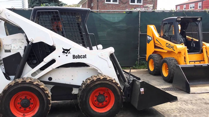
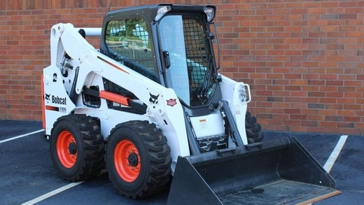
Bobcat s650 skid steer loader service manual
711 Pages in .pdf format
106 MB in .zip format for super fast downloads!
This factory BOBCAT Service Manual Download will give you complete step-by-step information on repair, servicing, and preventative maintenance for your Bobcat. The Bobcat Service Manual is highly detailed with photos and illustrations to help guide you through every service, repair, and troubleshooting procedure. This Bobcat online manual contains all you need to know to keep your Bobcat working right and is the only service repair manual you will need. It will help you understand, care for, and lower the repair and maintenance cost for your Bobcat.
This Bobcat s650 skid steer loader service manual is the same service manual used by professional Bobcat technicians.
CONTENTS AS FOLLOWS:
Foreword
Safety & Maintenance
Hydraulic System
Hydrostatic System
Drive System
Mainframe
Electrical System and Analysis
Engine Service
Heating, Ventilation, Air Conditioning (HVAC)
Specifications
Hydraulic and Electric shematics
All the pages of this Bobcat online manual download are printable, so print what you need and take it with you into the garage or workshop. Save money $$ by doing your own repairs! These BOBCAT Manuals make it easy for any skill level with these very easy to follow, step-by-step instructions! Instant online download means no shipping cost or waiting for a CD to arrive in the mail… you will receive this Bobcat Service Manual via instant download immediately after payment via our secure payment processor. The Bobcat manual will be yours to keep! We accept all major credit/debit cards/paypal.
The post Bobcat s650 skid steer loader service manual Download appeared first on Bobcat Service Manual.
Source: bobcat
(S/N: A3NV11001 & Above – S/N: A3NW11001 & Above)
–
This workshop repair service manual PDF download for the S650 Bobcat Skid-Steer Loader has been prepared as an aid to improve the quality of repairs by giving the serviceman an accurate understanding of the product and by showing him the correct way to perform repairs and make judgements. Make sure you understand the contents of this manual and use it to fully at every opportunity.
APPLICABLE MODELS :
Bobcat Loader S650
S/N: A3NV11001 & Above
S/N: A3NW11001 & Above
TABLE OF CONTENTS :
SAFETY & MAINTENANCE
HYDRAULIC SYSTEM
HYDROSTATIC SYSTEM
DRIVE SYSTEM
MAINFRAME
ELECTRICAL SYSTEM & ANALYSIS
ENGINE SERVICE
HEATING, VENTILATION, AIR CONDITIONING
SPECIFICATIONS
ALPHABETICAL INDEX
SERVICE MANUAL REVISION
MANUAL SPECIFICATION :
File Format : PDF
Language : English
Printable : Yes
Searchable : Yes
Bookmarked : Yes
P/N : 6987168 (10-10)
Total Pages : 896
This Bobcat Skid-Steer Loader Service / Repair / Workshop Manual PDF Download contains specs, diagrams, actual real photo illustrations, and schemes. In addition to space savings, nice thing about having completly searcheble PDF files instead of a hard-printed manual is that you can use the Search feature in your PDF reader software (Adobe Acrobat) to find just what your looking for and just print out the exact pages you need or all manual easily. This is the same manual your local dealer will use when doing a repair. This is a must for the Do-It-Yourselfer! Saving Yourself $$$$$$ In Service Repair And Maintenance Costs !!!!
Sellfy Instant Download means there is NO shipping costs or waiting for a CD or paper manual to arrive in the mail! You will receive this manual TODAY via Instant Download on completion of payment via our secure payment processor. We accept ALL major credit/debit cards/paypal.
–
MAINTENANCE SAFETY
CONTENTS
FOREWORD
FOREWORD
SAFETY INSTRUCTIONS
FIRE PREVENTION
Maintenance
Operation
Electrical
Hydraulic System
Fueling
Starting
Spark Arrestor Exhaust System
Welding And Grinding
Fire Extinguishers
SERIAL NUMBER LOCATIONS
Loader Serial Number
Engine Serial Number
DELIVERY REPORT
LOADER IDENTIFICATION
SAFETY & MAINTENANCE
LIFTING AND BLOCKING THE LOADER
Procedure
LIFT ARM SUPPORT DEVICE
Installing
Removing
OPERATOR CAB
Description
Raising
Lowering
Cab Door Sensor
Special Applications Kit
Special Applications Kit Inspection And Maintenance
TRANSPORTING LOADER ON A TRAILER
Loading And Unloading
Fastening
TOWING THE LOADER
Procedure
REMOTE START TOOL KIT-MEL1563
Remote Start Tool – MEL1563
Service Tool Harness Control – MEL1565
Service Tool Harness Communicator – MEL1566
Remote Start Procedure
REMOTE START TOOL (SERVICE TOOL) KIT – 7003031
Description
Remote Start Tool (Service Tool) – 7003030
Loader Service Tool Harness – 6689747
Computer Service Tool Harness – 6689746
Remote Start Procedure
SERVICE SCHEDULE
Chart
AIR CLEANER SERVICE
Replacing Filter Elements
ENGINE COOLING SYSTEM
Maintenance Platform
Cleaning
Checking Level
Removing And Replacing Coolant
FUEL SYSTEM
Fuel Specifications
Biodiesel Blend Fuel
Filling The Fuel Tank
Fuel Filter
Removing Air From The Fuel System
ENGINE LUBRICATION SYSTEM
Checking And Adding Engine Oil
Engine Oil Chart
Removing And Replacing Oil And Filter
HYDRAULIC/HYDROSTATIC SYSTEM
Checking And Adding Fluid
Hydraulic / Hydrostatic Fluid Chart
Removing And Replacing Hydraulic Fluid
Removing And Replacing Hydraulic / Hydrostatic Filter
Removing And Replacing Hydraulic Charge Filter
Breather Cap
FINAL DRIVE TRANSMISSION (CHAINCASE)
Checking And Adding Oil
Removing And Replacing Oil
BOB-TACH (HAND LEVER)
Inspection And Maintenance
BOB-TACH (POWER)
Inspection And Maintenance
LUBRICATING THE LOADER
Lubrication Locations
TIRE MAINTENANCE
Wheel Nuts
Rotating
Mounting
SPARK ARRESTOR MUFFLER
Cleaning Procedure
PIVOT PINS
Inspection And Maintenance
LOADER STORAGE AND RETURN TO SERVICE
Storage
Return To Service
STOPPING THE ENGINE AND LEAVING THE LOADER
Procedure
EMERGENCY EXIT
External Access
Rear Window
Front Door
SEAT BELT
Inspection And Maintenance
HYDRAULIC SYSTEM
HYDRAULIC / HYDROSTATIC SCHEMATICS
HYDRAULIC SYSTEM INFORMATION
Glossary Of Hydraulic / Hydrostatic Symbols
Troubleshooting
CYLINDER (LIFT)
Testing
Removal And Installation
Parts Identification
Disassembly
Assembly
CYLINDER (TILT)
Testing
Removal And Installation
Base End Pivot Pin Removal And Installation
Parts Identification
Disassembly
Assembly
CYLINDER (BOB-TACH)
Testing
Removal And Installation
Parts Identification
Disassembly
Assembly
MAIN RELIEF VALVE
Description
Testing
Adjusting
Removal And Installation
HYDRAULIC CONTROL VALVE (STANDARD)
Description
Removal And Installation
Mount Bracket Removal And Installation
Identification Chart
Lift Load Check Valve Removal And Installation
Load Check Valve Removal And Installation (Tilt & Auxiliary)
Anti-Cavitation Valve Removal And Installation (Lift, Rod End)
Port Relief / Anti-Cavitation Valve Removal And Installation (Lift, Base End)
Port Relief / Anti-Cavitation Valve Removal And Installation (Tilt, Base End)
Port Relief / Anti-Cavitation Valve Removal And Installation (Tilt, Rod End)
Port Relief Valve Removal And Installation
Plug Removal And Installation
Rubber Boot Removal And Installation
End Cap Block Removal And Installation
Lift Spool And Detent Removal And Installation
Tilt Spool Removal And Installation
Auxiliary Spool Removal And Installation
Auxiliary Solenoid Removal And Installation
Solenoid Removal And Installation
Lock Valve Removal And Installation
Lift Arm Bypass Orifice Removal And Installation
Main Relief Valve Removal And Installation
Check Valve Removal And Installation
HYDRAULIC CONTROL VALVE (ACS) OR (SJC)
Description
Removal And Installation
Actuator Removal And Installation (In Loader)
Actuator Removal And Installation (Out Of Loader)
Identification Chart
Mount Bracket Removal And Installation
Lift Load Check Valve Removal And Installation
Load Check Valve Removal And Installation (Tilt & Auxiliary)
Anti-Cavitation Valve Removal And Installation (Lift, Rod End)
Port Relief / Anti-Cavitation Valve Removal And Installation (Lift, Base End)
Port Relief / Anti-Cavitation Valve Removal And Installation (Tilt, Base End)
Port Relief / Anti-Cavitation Valve Removal And Installation (Tilt, Rod End)
Port Relief Valve Removal And Installation
Plug Removal And Installation
End Cap Block Removal And Installation
Lift Spool Removal And Installation
Tilt Spool Removal And Installation
Auxiliary Spool Removal And Installation
Auxiliary Solenoid Removal And Installation
Solenoid Removal And Installation
Lock Valve Removal And Installation
Lift Arm Bypass Orifice Removal And Installation
Main Relief Valve Removal And Installation
Check Valve Removal And Installation
LIFT ARM BYPASS CONTROL VALVE
Description
Testing
Removal And Installation
Bracket Removal And Installation
Disassembly And Assembly
HYDRAULIC PUMP
Description
Pump Test At Quick Couplers
Direct Pump Test (Standard Section)
Direct Pump Test (Charge Section)
Removal And Installation
Hydraulic Pump Startup
Parts Identification
Disassembly And Assembly
HYDRAULIC PUMP (HIGH FLOW)
Description
Pump Test At Quick Couplers
Direct Pump Test (Standard Section)
Direct Pump Test (Charge Section)
Direct Pump Test (High Flow Section)
High Flow Relief Valve Adjustment
High Flow Relief Valve Removal And Installation
Solenoid Removal And Installation
Removal And Installation
Hydraulic Pump Startup
Parts Identification
Disassembly And Assembly
HYDRAULIC / HYDROSTATIC FILTERS
Description
Housing Removal And Installation
HYDRAULIC FLUID RESERVOIR
Description
Removal And Installation
Hydraulic Fluid Screen
OIL COOLER
Description
Removal And Installation
BUCKET POSITION VALVE
Description
Solenoid Removal And Installation
Solenoid Testing
Removal And Installation
Disassembly And Assembly
REAR AUXILIARY DIVERTER VALVE
Description
Solenoid Testing
Removal And Installation
Disassembly And Assembly
BOB-TACH (POWER) BLOCK
Description
Removal And Installation
Disassembly And Assembly
FRONT AUXILIARY HYDRAULIC COUPLER BLOCK
Description
Removal And Installation
Disassembly And Assembly
HYDROSTATIC SYSTEM
HYDROSTATIC SYSTEM INFORMATION
Troubleshooting
Description
HYDROSTATIC DRIVE MOTOR
Description
Removal And Installation
Parts Identification
Disassembly And Assembly
HYDROSTATIC DRIVE MOTOR (TWO-SPEED)
Description
Removal And Installation
Parts Identification
Disassembly
Assembly
HYDROSTATIC MOTOR CARRIER
Description
Removal And Installation
Parts Identification
Disassembly
Assembly
HYDROSTATIC MOTOR CARRIER (SJC)
Description
Removal And Installation
Parts Identification
Disassembly
Assembly
CHARGE PRESSURE
Description
Testing
Sender Removal And Installation
Adjusting
HYDROSTATIC PUMP
Description
Removal And Installation
Hydrostatic Pump Startup
Replenishing / High Pressure Relief Valve Removal And Installation
Parts Identification (Left Half)
Parts Identification (Right Half)
Disassembly
Assembly
HYDROSTATIC PUMP (SJC)
Description
Hydraulic Controller Removal And Installation
Removal And Installation
Hydrostatic Pump Start Up
Parts Identification
High Pressure Relief And Bypass Valve
Charge Relief Valve
Disassembly And Assembly
Mechanical Neutral Adjustment
Hydraulic Controller Neutral Adjustment
DRIVE BELT
Belt Adjustment
Belt Replacement
Stop Adjustment
Tensioner Pulley Removal And Installation
Tensioner Pulley Disassembly And Assembly
TWO-SPEED / BRAKE VALVE
Description
Valve Block Removal And Installation
Valve Block Disassembly And Assembly
DRAIN MANIFOLD
Description
Drain Manifold Removal And Installation
DRIVE SYSTEM
BRAKE (SINGLE SPEED)
Description
Disc Removal And Installation
BRAKE (TWO-SPEED)
Description
DRIVE COMPONENTS
Description
Axle Seal Removal And Installation
Axle, Sprocket And Bearings Removal And Installation
Chain Removal And Installation
CHAINCASE
Description
Front Cover Removal And Installation
Center Cover Removal And Installation
Rear Cover Removal And Installation
MAINFRAME
SEAT BAR
Description
Removal And Installation
Disassembly And Assembly
Compression Spring Disassembly And Assembly
OPERATOR CAB
Gas Spring Removal And Installation
Gas Spring Bracket Disassembly And Assembly
Removal And Installation
OPERATOR SEAT
Removal And Installation
Seat Belt Removal And Installation (Retractable)
Seat Belt And Bracket Removal And Installation (Standard)
Seat Belt Bracket Removal And Installation
OPERATOR SEAT (SUSPENSION)
Removal And Installation
Slide Rail Removal And Installation
Seat Belt Removal And Installation
Lower Cushion Removal
Lower Cushion Installation
Back Cushion Removal And Installation
Shock Removal And Installation
3-Point Seat Belt Removal And Installation
BOB-TACH (HAND LEVER)
Description
Removal And Installation
Lever And Wedge Disassembly And Assembly
Pivot Pin Bushing And Seal Removal And Installation
BOB-TACH (POWER)
Description
Removal And Installation
Lever And Wedge Disassembly And Assembly
Pivot Pin Bushing And Seal Removal And Installation
LIFT ARMS
Stabilizer Bar Removal And Installation
Link Removal And Installation
Removal And Installation
REAR GRILLE
Removal And Installation
REAR DOOR (TAILGATE)
Removal And Installation
Striker Removal And Installation
Striker Disassembly And Assembly
Striker (Adjusting)
Latch Removal And Installation
FUEL TANK
Removal And Installation
Fuel Level Sender Removal And Installation
Fuel Fill Screen Removal And Installation
CONTROL PEDALS AND LINKAGES
Description
Pedal Removal And Installation
Linkage Removal And Installation
Pedal (Adjusting)
Floor Pan Removal And Installation
CONTROL PEDALS AND LINKAGES (ACS)
Description
Pedal Removal And Installation
Linkage Removal And Installation
Pedal (Adjusting)
Floor Pan Removal And Installation
CONTROL PANEL
Description
Removal And Installation
Disassembly And Assembly
Linkage Removal And Installation
Pintle Arm Disassembly And Assembly
Linkage Neutral (Adjusting)
Linkage Travel (Adjusting)
Shock Removal And Installation
CONTROL PANEL (SJC)
Description
Removal And Installation
CONTROL HANDLE / LEVER
Description
Lever Removal And Installation
Boot Removal And Installation
CONTROL HANDLE / LEVER (ACS)
Description
Handle Sensor Removal And Installation
Handle Removal And Installation
Handle Disassembly And Assembly
Lever Removal And Installation
Boot Removal And Installation
CONTROL HANDLE / LEVER (SJC)
Description
Joystick Testing
Joystick Removal And Installation
ACCESS PANEL (INSIDE)
Removal And Installation (Left)
Removal And Installation (Right)
ACCESS PANEL (INSIDE) (SJC)
Removal And Installation (Left)
Removal And Installation (Right)
WINDOW (REAR)
Removal And Installation
Disassembly And Assembly
WINDOW (TOP)
Removal And Installation
WINDOW (SIDE)
Removal And Installation
CAB DOOR
Description
Removal And Installation
Disassembly And Assembly
Aligning
Adjusting
Checking Operation
ARMREST
Description
Removal And Installation
Disassembly And Assembly
LEFT SIDE LOWER PANEL
Removal And Installation
Disassembly And Assembly
RIGHT SIDE LOWER PANEL
Removal And Installation
Disassembly And Assembly
HEADLINER
Removal And Installation
ELECTRICAL SYSTEM & ANALYSIS
ELECTRICAL SCHEMATICS
ELECTRICAL SYSTEM INFORMATION
Glossary Of Electrical Symbols
Standard Cab Harness Connectors
Deluxe Cab Harness Connectors
Mainframe Harness Connectors
Description
Troubleshooting
Fuse And Relay Location / Identification
Solenoid Testing
BATTERY
Removal And Installation
Servicing
Using A Booster Battery (Jump Starting)
ALTERNATOR
Belt Adjustment
Belt Replacement
Charging System Inspection
Alternator Voltage Testing
Low Voltage Testing
High Voltage Testing
Removal And Installation
Parts Identification
STARTER
Testing
Removal And Installation
Parts Identification
INSTRUMENT PANELS
Left Panel
Display Screen
Right Panel (Standard Key Panel)
Right Panel (Keyless Start Panel)
Right Panel (Deluxe Instrumentation Panel)
Left Switch Panel
Right Switch Panel
Left Panel Removal And Installation
Right Panel (Standard Key Panel) Removal And Installation
Right Panel (Keyless Start Panel) Removal And Installation
Right Panel (Deluxe Instrumentation Panel) Removal And Installation
Key Switch Disassembly And Assembly
Alarm Disassembly And Assembly
Left Switch Panel Removal And Installation
Right Switch Panel Removal And Installation
LIGHTS
Front Removal And Installation
Rear Removal And Installation
Cab Light Removal And Installation
BOBCAT CONTROLLERS (GATEWAY AND AUXILIARY)
Description
Connector Identification
Removal And Installation
BOBCAT CONTROLLER (ACS)
Description
Connector And Wire Identification
Removal And Installation
BOBCAT CONTROLLER (SJC) (DRIVE)
Description
Connector Identification
Removal And Installation
SPEED SENSORS (SJC)
Description
Testing
Removal And Installation
DIAGNOSTIC SERVICE CODES
Viewing Service Codes
Service Codes List
BOBCAT INTERLOCK CONTROL SYSTEM (BICS)
Description
Inspecting The BICS (Engine STOPPED – Key ON)
Inspecting Deactivation Of The Auxiliary Hydraulics System (Engine STOPPED – Key ON)
Inspecting The Seat Bar Sensor (Engine RUNNING)
Inspecting The Traction Lock (Engine RUNNING)
Inspecting The Lift Arm Bypass Control
Inspecting Deactivation Of Lift And Tilt Functions (ACS And SJC)
Troubleshooting
SEAT BAR SENSOR
Description
Troubleshooting
Testing
Removal And Installation
Bobcat Interlock Control System (BICS) Circuit Test
TRACTION LOCK
Description
Troubleshooting
Inspecting
CONTROL SYSTEM (ACS)
Description
Troubleshooting
Handle Sensor Connector Disassembly And Assembly
Switch Handle Removal
Switch Handle Installation
Actuator Connector Disassembly And Assembly
Handle Lock Solenoid Removal And Installation
Handle Lock Solenoid Disassembly And Assembly
Foot Sensor Removal And Installation
Foot Sensor Disassembly And Assembly
Foot Sensor Lock Solenoid Removal And Installation
ELECTRICAL / HYDRAULIC CONTROLS
Identification Chart
Description
Identification Chart ACD Group 0
Identification Chart ACD Group 1
Identification Chart ACD Group 2
Identification Chart ACD Group 3
ELECTRICAL / HYDRAULIC CONTROLS (ACS)
Identification Chart
Description
Identification Chart ACD Group 0
Identification Chart ACD Group 1
Identification Chart ACD Group 2
Identification Chart ACD Group 3
ELECTRICAL / HYDRAULIC CONTROLS (SJC)
Identification Chart
Description
Identification Chart ACD Group 0
Identification Chart ACD Group 1
Identification Chart ACD Group 2
Identification Chart ACD Group 3
SERVICE PC (LAPTOP COMPUTER)
Connecting Remote Start Tool
Connecting Remote Start Tool (Service Tool)
CALIBRATION
Description
Actuator Testing
Lift And Tilt Calibration (SJC)
Hydrostatic Pump Calibration (SJC)
Lift And Tilt Calibration (ACS)
STEERING DRIFT COMPENSATION
Description
Operation
FLYWHEEL RPM SENSOR
Description
Adjustment
CONTROL PANEL SETUP
Right Panel Setup (Deluxe Instrumentation Panel)
PASSWORD SETUP (DELUXE INSTRUMENTATION PANEL)
Password Description
Changing The Owner Password
Changing The User Passwords
Password Lockout Feature
PASSWORD SETUP (KEYLESS START PANEL)
Password Description
Changing The Owner Password
Password Lockout Feature
MAINTENANCE CLOCK
Description
Setup
Reset
BACK-UP ALARM SYSTEM
Description
Inspecting
Adjusting Switch Position
Troubleshooting (Standard And ACS)
Troubleshooting (Joystick)
Alarm Removal And Installation
Switch Removal And Installation
FRONT HORN
Removal And Installation
ENGINE SERVICE
ENGINE INFORMATION
Description
Specifications
Torque Values
Troubleshooting
Engine Removal And Installation
Engine Mount Replacement
Compression – Checking
ENGINE SPEED CONTROL
Removal And Installation
Disassembly And Assembly
Cable Removal And Installation
ENGINE SPEED CONTROL (SJC) S/N A3NV12469 AND BELOW & S/N A3NW11130 AND BELOW
Removal And Installation
Disassembly And Assembly
ENGINE SPEED CONTROL (SJC) S/N A3NV12470 AND ABOVE & S/N A3NW11131 AND ABOVE
Removal And Installation
Disassembly And Assembly
MUFFLER
Removal And Installation
AIR CLEANER
Housing Removal And Installation
Housing Bracket Removal And Installation
ENGINE COOLING SYSTEM
Radiator Removal And Installation
Hydraulic Fan Description
Hydraulic Fan Disassembly And Assembly
Lower Fan Duct Removal And Installation
Blower Housing Removal And Installation
Hydraulic Fan Motor Assembly Removal And Installation
Fan Removal And Installation
Hydraulic Fan Motor Removal And Installation
Water Pump Removal And Installation
Water Pump Disassembly And Assembly
Thermostat Housing Removal And Installation
Thermostat – Checking
LUBRICATION SYSTEM
Oil Pan Removal And Installation
Oil Pump Removal And Installation
Relief Valve – Testing
Oil Pump Inspection
Oil Filter Cooler Removal And Installation
Engine Oil Pressure – Testing
FUEL SYSTEM
Fuel Shutoff Solenoid – Checking
Fuel Shutoff Solenoid Removal And Installation
Fuel Injection Pump – Checking
Fuel Injection Pump Assembly Removal And Installation
Governor Housing Disassembly And Assembly
Governor Disassembly And Assembly
Fuel Camshaft Removal And Installation
Fuel Injection Pump Removal And Installation
Fuel Injection Pump – Timing
Fuel Injector Removal And Installation
Fuel Injector Nozzle Pressure – Checking
Nozzle Spray Condition
Valve Seat Tightness
CYLINDER HEAD
Glow Plugs – Testing
Glow Plugs Removal And Installation
Valve Clearance Adjustment
Valve Timing – Checking
Cylinder Head Removal And Installation
Cylinder Head Disassembly And Assembly
Cylinder Head – Servicing
Cylinder Head Top Clearance
Valve Guide – Checking
Valve Guide Removal And Installation
Reconditioning The Valve And Valve Seat
Valve Spring
Valve Tappets
Rocker Arm And Shaft – Checking
Bridge Arm And Bridge Arm Shaft – Checking
Bridge Arm Shaft – Removal And Installation
Push Rod Alignment – Checking
CRANKSHAFT AND PISTONS
Piston And Connecting Rod Removal And Installation
Piston And Connecting Rod – Servicing
Cylinder Bore – Checking
Connecting Rod Alignment
Crankshaft Gear Removal And Installation
Crankshaft And Bearings Removal And Installation
Crankshaft And Bearings – Servicing
CAMSHAFT AND TIMING GEARS
Timing Gearcase Cover Removal
Timing Gearcase Cover Installation
Timing Gears Backlash – Checking
Idler Gear And Camshaft Removal And Installation
Camshaft – Servicing
Idler Gear And Shaft – Servicing
TURBOCHARGER
Description
Testing
Removal And Installation
FLYWHEEL AND HOUSING
Flywheel Removal And Installation
Ring Gear Removal And Installation
Housing Removal And Installation
EXHAUST GAS RECIRCULATION (EGR) SYSTEM
Description
Testing
Removal And Installation
Disassembly And Assembly
HEATING, VENTILATION, AIR CONDITIONING
AIR CONDITIONING SYSTEM FLOW
Description
Chart
Components
Safety Equipment
REGULAR MAINTENANCE
Filters
Compressor Drive Belt Adjustment
Compressor Drive Belt Replacement
Condenser
Air Conditioning Lubrication
Air Conditioning Service Chart
Evaporator / Heater Coil
TROUBLESHOOTING
Blower Motor Does Not Operate
Blower Motor Operates Normally, But Air Flow Is Insufficient
Insufficient Cooling Although Air Flow And Compressor Operation Are Normal
The Compressor Does Not Operate At All, Or Operates Improperly
Gauge Pressure Related Troubleshooting
Troubleshooting Tree
Temperature / Pressure Chart
Poor A/C Performance
HVAC Repair And Leaks
Electrical System
Engine Coolant Bypassing The Heater Valve
Heater Valve Not Opening Or Closing
SYSTEM CHARGING AND RECLAMATION
Refrigerant Identification
Reclamation And Charging With Recovery / Charging Unit
COMPRESSOR
Removal And Installation
Oil
Oil Check
CONDENSER
Removal And Installation
RECEIVER / DRIER
Receiver / Drier Removal And Installation
Pressure Relief Valve Removal And Installation
Pressure Switch Removal And Installation
Schraeder Valve Removal And Installation
EVAPORATOR / HEATER UNIT
Removal And Installation
THERMOSTAT
Description
Removal And Installation
EXPANSION VALVE
Removal And Installation
EVAPORATOR COIL
Removal And Installation
HEATER COIL
Removal And Installation
BLOWER FAN
Removal And Installation
Disassembly And Assembly
HEATER VALVE
Removal And Installation
SPECIFICATIONS
(S650) LOADER SPECIFICATIONS
Machine Dimensions
Performance
Engine
Drive System
Controls
Hydraulic System
Electrical System
Capacities
Tires
TORQUE SPECIFICATIONS FOR BOLTS
Torque For General SAE Bolts
Torque For General Metric Bolts
HYDRAULIC CONNECTION SPECIFICATIONS
Straight Thread O-ring Fitting
Flare Fitting
Tubelines And Hoses
HYDRAULIC / HYDROSTATIC FLUID SPECIFICATIONS
Specifications
CONVERSIONS
Decimal And Millimeter Equivalent Chart
U.S. To Metric Conversion Chart
ALPHABETICAL INDEX
SERVICE MANUAL REVISION
Revision No: S650 – 1
Revision No: S650 – 2
Revision No: S650 – 3
Revision No: S650 – 4
Revision No: S650 – 5
Revision No: S650 – 6
Revision No: S650 – 7
–

Marmion Collin
12 Sep 2023
Carlos Maldonado
12 Sep 2023
Massinissa Boudjemai
13 Sep 2023
Charles Healy
13 Sep 2023
Jordan Mighell
13 Sep 2023
Jaime L. Johnson
14 Sep 2023
Dennis G. Lee
14 Sep 2023
Valentine Fedorov
14 Sep 2023
Joseph M. Morley
14 Sep 2023
Heavy Equipment Manual
Tax included.
Bobcat S650 Skid Steer Loader Service Repair Manual (6987168)
We Offers Manual HIGH quality images, diagrams, instructions to help you to operate, maintenance, diagnostics and repair your truck. This document is printable, without restrictions, contains searchable text, bookmarks, crosslinks for easy navigation.
MODELS COVERED:
S650
FILE FORMAT: PDF
LANGUAGE: ENGLISH
DELIVERY: INSTANT DOWNLOAD
REQUIREMENTS: ADOBE PDF READER
COMPATIBLE ALL VERSIONS OF WINDOWS AND MAC
Back to Bobcat Manual Download PDF