Introduction
FBQ Feedback Detection System
The FBQ Feedback Detection System, integrated into the graphic equalizer, is one of the most outstanding characteristics of this mixing console. This ingenious circuitry lets you immediately recognize and eliminate feedback frequencies. The FBQ Feedback Detection System uses the LEDs in the frequency band faders of the graphic EQ to indicate the critical frequencies. This way, what once used to be a labor-intensive search for feedback frequencies is now an activity that even a child could master.
The microphone channels feature high-end XENYX Mic Preamps that compare well with costly outboard preamps in terms of sound quality and dynamics and boast the following features:
- 130 dB dynamic range for an incredible amount of headroom
- A bandwidth ranging from below 10 Hz to over 200 kHz for crystal-clear reproduction of even the finest nuances
- The extremely low-noise and distortion-free circuitry guarantees absolutely natural and transparent signal reproduction
- They are perfectly matched to every conceivable microphone with up to 60 dB gain and +48 volt phantom power supply
- They enable you to use the greatly extended dynamic range of your 24-bit/192 kHz HD recorder to the full, thereby maintaining optimal audio quality
«British EQ»
The equalizers used for the XENYX Series are based on the legendary circuitry of top-notch consoles made in Britain, which are renowned throughout the world for their incredibly warm and musical sound character. Even with extreme gain settings these equalizers ensure outstanding audio properties.
Multi-effects processor
Additionally, your XENYX mixing console has an effects processor with 24-bit A/D and D/A converters included, which gives you 16 presets producing first-class reverb, delay and modulation effects plus numerous multi-effects in excellent audio quality.
The XENYX mixing consoles are equipped with a state-of-the-art switched-mode power supply (SMPS). Unlike conventional circuitry an SMPS provides an optimum supply current regardless of the input voltage. And thanks to its considerably higher efficiency a switched-mode power supply uses less energy than conventional power supplies.
We would like to draw your attention to the fact that extreme volumes may damage your hearing and/or your headphones or loudspeakers. Turn the MAIN MIX faders and the PHONES control in the main section fully down before you switch on the unit. Always be careful to set the appropriate volume.
General mixing console functions
A mixing console fulfils three main functions:
- Signal processing:
Preamplification
Microphones convert sound waves into voltage that has to be amplified several-fold; then, this voltage is turned into sound that is reproduced in a loudspeaker. Because micro phone capsules are very delicate in their construction, output voltage is very low and therefore susceptible to interference. Therefore, mic signal voltage is amplified directly at the mixer input to a higher signal level that is less prone to interference. This higher, interference-safe signal level has to be achieved through amplification using an amplifier of the highest quality in order to amplify the signal and add as little noise to it as possible. The XENYX Mic Preamp performs this role beautifully, leaving no traces of noise or sound coloration. Interference that could take place at the preamplification level could affect signal quality and purity, and would then be passed on to all other devices, resulting in inaccurate sounding program during recording or playback.
Level-setting
Signals fed into the mixer using a DI-box (Direct Injection) or the output of a sound card or a keyboard, often have to be adjusted to the operating level of your mixing console.
Frequency response correction
Using the equalizers found in each channel strip, you can simply, quickly and effectively adjust the way a signal sounds.
Effects mixing
In addition to the effects processor contained in your mixer, using the insert connectors on the mono channels and both aux busses lets you insert additional signal processors into your signal path. - Signal distribution:
Individual signals adjusted at each channel strip are laid out at the aux sends and returns, and are either fed into external effects processors or fed back to the internal effects processor. Then, the signals are brought back into the main mix either via the aux return connectors or via direct internal wiring. The mix for the on-stage musicians is also created using the aux sends (monitor mix). Similarly, for example, signals for recording equipment, power ampli fiers, headphones and 2-track outputs can also be taken. - Mix:
All other mixing console functions fall under this vital category. Creating a mix means primarily adjusting the volume levels of individual instruments and voices to one another as well as giving them the appropriate weight within the overall frequency spectrum. Likewise, you’ll have to sensibly spread individual voices across the stereo image of a signal. At the end of this process, adjusting the level of the entire mix to other equipment in the signal path is required (e.g. recorder/crossover/amplifier). The interface of BEHRINGER mixing consoles is optimized for these tasks, enabling you to easily keep track of the signal path.
The user’s manual
The user’s manual is designed to give you both an overview of the controls, as well as detailed information on how to use them. In order to help you understand the links between the controls, we have arranged them in groups according to their function.
Before you get started
Shipment
Your mixing console was carefully packed in the factory to guarantee safe transport. Nevertheless, we recommend that you carefully examine the packaging and its contents for any signs of physical damage, which may have occurred during transit.
- If the unit is damaged, please do NOT return it to us, but notify your dealer and the shipping company immediately, otherwise claims for damage or replacement may not be granted.
Initial operation
Be sure that there is enough space around the unit for cooling purposes and to avoid over-heating. Please do not place your mixing console on high-temperature devices such as radiators or power amps. The console is connected to the mains via the supplied power cable. The console meets the required safety standards. Blown fuses must only be replaced by fuses of the same type and rating.
- Please note that all units must be properly grounded. For your own safety, you should never remove any ground connectors from electrical devices or power cables, or render them in operative.
- Please ensure that only qualified people install and operate the mixing console. During installation and operation, the user must have sufficient electrical contact to earth, otherwise electrostatic discharges might affect the operation of the unit.
Online registration
Please do remember to register your new BEHRINGER equipment right after your purchase by visiting behringer.com (alternatively behringer.de) and kindly read the terms and conditions of our warranty carefully.
Should your BEHRINGER product malfunction, our goal is to have it repaired as quickly as possible. To arrange for warranty service, please contact the retailer from whom the equipment was purchased. Should your BEHRINGER dealer not be located in your vicinity, you may directly contact one of our subsidiaries. Corresponding contact information is included in the original equipment packaging (Global Contact Information/European Contact Information). Should your country not be listed, please contact the distributor nearest you. A list of distributors can be found in the support area of our website (behringer.com).
Registering your purchase and equipment with us helps us process your repair claims quicker and more efficiently.
Thank you for your cooperation!
Control Elements and Connectors
This chapter describes the various control elements of your mixing console. All controls, switches and connectors will be discussed in detail.
Mono channels
Microphone and line inputs

MIC
Each mono input channel offers a balanced microphone input via the XLR connector and also features switchable +48 V phantom power supply for condenser microphones. The XENYX preamps provide undistorted and noise-free gain as is typically known only from costly outboard preamps.
- Please mute your playback system before you activate the phantom power supply to prevent switch-on thumps being directed to your loud speakers. Please also note the instructions in chapter 2.5 «Rear view of X1222USB».
LINE IN
Each mono input also features a balanced line input on a ¼» connector.
Unbalanced devices (mono jacks) can also be connected to these inputs.
- Please remember that you can only use either the microphone or the line input of a channel at any one time. You can never use both simultaneously!
INSERT
Insert points enable the processing of a signal with dynamic processors or equalizers. They are sourced pre-fader, pre-EQ and pre-aux send. Unlike reverb or other effects devices, whose signals are usually added to the dry signal, dynamic processors are most effective on the complete signal. In this case, aux send paths are a less-than-perfect solution. It is better to interrupt the signal path and insert a dynamic processor and/or equalizer. After processing, the signal is routed back to the console at precisely the same point it left. However, the channel signal path is interrupted only if a plug is inserted into the corresponding jack (stereo phone plug: tip = signal output; ring = return input). All mono input channels are equipped with inserts.
Inserts can also be used as pre-EQ direct outputs, without interrupting the signal path. To this end, you will need a cable fitted with mono phone plugs on the tape machine or effects device end, and a bridged stereo phone plug on the console side (tip and ring connected).
LOW CUT
The mono channels of the mixing consoles have a high-slope LOW CUT filter for eliminating unwanted, low-frequency signal components (80 Hz, 18 dB/octave).
GAIN
Use the GAIN control to adjust the input gain. This control should always be turned fully counter-clockwise whenever you connect or disconnect a signal source to one of the inputs.
The scale has 2 different value ranges: the first value range (+10 to +60 dB) refers to the MIC input and shows the amplification for the signals fed in there.
The second value range (+10 to -40 dB) refers to the line input and shows its sensitivity. The settings for equipment with standard line-level signals (-10 dBV or +4 dBu) look like this: While the GAIN control is turned all the way down, connect your equipment. Set the GAIN control to the external devices’ standard output level. If that unit has an output signal level display, it should show 0 dB during signal peaks. For +4 dBu, turn up GAIN slightly, for -10 dBV a bit more. Tweaking is done using the LEVEL SET LED.
LEVEL SET
This LED lights up when the optimum operating signal level is achieved. During normal use, this LED should only light up during signal peaks.
COMPRESSOR
Each mono channel features a built-in compressor which lowers the dynamic range of the signal and increases its perceived loudness. The loud peaks are squashed down and the quiet sections are boosted.
Turn the COMP knob clockwise to add more compression effect. The adjacent LED with light when the effect is engaged.
Equalizer
All mono input channels include a 3-band equalizer. All bands provide boost or cut of up to 15 dB. In the central position, the equalizer is inactive.
The circuitry of the British EQs is based on the technology used in the best-known top-of-the-line consoles and providing a warm sound without any unwanted side effects. The result are extremely musical equalizers which, unlike simple equalizers, cause no side effects such as phase shifting or bandwidth limitation, even with extreme gain settings of ±15 dB.
The upper (HIGH) and the lower band (LOW) are shelving filters that increase or decrease all frequencies above or below their cut-off frequency. The cut-off frequencies of the upper and lower band are 12 kHz and 80 Hz respectively. The mid band is configured as a peak filter with a center frequency of 2.5 kHz. Unlike shelving filters, the peak filter processes a frequency range that extends upwards and downwards around its middle frequency.
Aux sends (MON and FX)

Aux sends take signals via a control from one or more channels and sum these signals to a so-called bus. This bus signal is sent to an aux send connector and then routed, for example, to an active monitor speaker or an external effects device. The return from an external effects device can then be brought back into the console via the aux return connectors.
For situations that require effects processing, the aux sends are usually switched post-fader so that the effects volume in a channel corresponds to the position of the channel fader. If this were not the case, the effects signal of the channel would remain audible even when the fader is turned to zero.
When setting up a monitor mix, the aux sends are generally switched to pre-fader; i.e. they operate independently of the position of the channel fader. Both aux sends are mono, are sourced after the equalizer and offer up to +15 dB gain.
- If you press the MUTE switch of the respective channel, aux sends and returns (MON and FX) are not being muted.
MON
In the X1222USB, aux send 1 (MON) is wired pre-fader and is thus particularly suitable for setting up monitor mixes.
FX
The aux send labeled FX is for feeding external effects devices and is thus set up to be post-fader.
In the X1222USB, the FX send is routed directly to the built-in effects processor. To make sure that the effects processor receives an input signal, you shouldn’t turn this control all the way to the left (-oo). Don’t have the FX MUTE switch pressed, and you should also not have the FX SEND fader pulled down.
Pan, mute switch and channel fader

PAN
The PAN control determines the position of the channel signal within the stereo image. This control features a constant-power characteristic, which means the signal is always maintained at a constant level, irrespective of position in the stereo panorama.
MUTE
Use the MUTE switch to mute the channel. This means that the channel signal is no longer present in the main mix. However, the aux sends (MON and FX) remain active.
MUTE LED
The MUTE LED indicates that the relevant channel is muted.
CLIP LED
The CLIP LED lights up when the input signal is driven too high. In this case, lower apparent frequency increase on the channel EQ to avoid distortion. For example, lower the mids and the highs somewhat to emphasize the bass. If you don’t wish to change the EQ settings under any circumstances, try lowering the GAIN control somewhat (counterclockwise).
If you inserted an external effects processor via the insert connector (e.g. a dynamic processor), then you should also control its output signal level. It should not be higher than its input signal level (0 dB).
The channel fader determines the level of the channel signal in the main mix.
Attention: Since the aux path for the effect processor is connected post-fader, the channel fader has to be turned up in order to get this channel’s signal to the effects processor!
Stereo channels
Channel inputs

Each stereo channel features two line-level inputs on ¼» connectors for left and right channels. Channels 9/10 and 11/12 can also be used in mono if you only use the connector labeled «L.»
Both channels 5/6 and 7/8 feature an additional balanced XLR input for microphones with available +48 V phantom power.
All stereo channel strips have a GAIN control for level setting. In those channels in which a mic input is present in the channel, the GAIN control has two scales: just like in the mono channels, there is a 0 to +40 dB scale that shows the preamplification of the mic signal; the +20 to -20 dB scale shows the sensitivity for the corresponding input level that is applied to the line input.
Both inputs can also be used with balanced or unbalanced connectors.
Equalizer stereo channels
The equalizer of the stereo channels is, of course, stereo. The filter characteristics and crossover frequencies are the same as those of the mono channels. A stereo equalizer is always preferable to two mono equalizers if frequency correction of a stereo signal is needed. There is often a discrepancy between the settings of the left and the right channels when using separate equalizers.
Aux sends stereo channels
In principle, the aux sends of the stereo channels function in just the same way as those of the mono channels. As aux send paths are always mono, the signal on a stereo channel is first summed to mono before it reaches the aux bus.
Balance, mute switch and channel fader
BAL
The function of the BAL(ANCE) control corresponds to the PAN control in the mono channels.
The balance control determines the relative proportion between the left and right input signals before both signals are routed to the main stereo mix bus.
The MUTE switch, MUTE LED, CLIP LED and channel fader function in the same way as the mono channels.
Connector panel and main section
Whereas it was useful to trace the signal flow from top to bottom in order to gain an understanding of the channel strips, we now look at the mixing console from left to right. The signals are, so to speak, collected from one point on each of the channel strips and then routed to the main section all together.
Monitor send and FX send channels

A channel signal is routed to the MON(ITOR) send bus if the MON control is turned up on the corresponding channel.
MON SEND
The aux send control MON SEND acts as master control for the monitor bus and determines the level of the summed signal that is taken from the mixer via the MON SEND connector and that can for example be fed to an amplifier for monitor purposes.
Using the audio signal from this output, you can also feed a subwoofer if you don’t require stage monitors. To this end, you should implement a crossover in your signal path pre-subwoofer and pre-amplifier, so that only low frequencies are fed into the subwoofer. You can achieve the same effect by using the built-in graphical equalizer. Lower all frequencies above 160 Hz and assign the equalizer to «Monitor».
- When you use the MAIN MIX fader to reduce the overall volume, keep in mind that the subwoofer is still receiving a signal!
FX TO MON
You can use this control to insert an effects signal from the built-in effects processor to your monitor mix. Of course, to do this, your effects processor must first receive a signal, i.e. the FX controls in the channel strips must be turned up, and the FX SEND fader (see fig. 2.6) hast to be open.
MON MUTE
If the MON MUTE switch is pressed, the monitor bus is muted, i.e. there is no signal at the MON SEND connector.
FX SEND
The FX SEND fader determines the overall level of the effects bus. Both external effects processors (via the FX SEND connector) and the built-in processor only receive an input signal if this control is open.
FX TO MAIN
Use the FX TO MAIN control to feed the effects signal into the main mix.
If the control is turned all the way to the left, no effects signal can be heard.
FX MUTE
If the FX MUTE switch is pressed, the effects channel is muted, i.e. no signal is present at the FX SEND connector and the effects processor no longer receives an input signal.
Monitor send and FX send connector

MON SEND
Connect the input of your monitor power amp or an active monitor system here to make the monitor mix audible to the musicians on the stage. The signal mix is created using the channels’ MON controls.
FX SEND
The FX SEND connector outputs the signal you picked up from the individual channels using the FX controls. You can connect this to the input of an external effects device in order to process the FX bus’ master signal. Once an effects mix is created, the processed signal can then be routed from the effects device outputs back into the AUX RETURN connectors.
- If the connected effects processor receives no input signal, the FX MUTE switch is probably pressed and/or the FX SEND control is too low. This also goes for the built-in effects processor.
- Adjust your external effects processor to 100% wet (effects signal only), because the effects signal is added to the main mix along with the «dry» channel signals.
Aux return connectors

AUX RETURN 1
The AUX RETURN 1 connectors generally serve as the return path for the effects mix generated using the FX send. This is where you connect the output signal of the external effects device. If only the left connector is used, the aux return 1 automatically operates in mono.
- You can also use these connectors as additional line inputs.
AUX RETURN 2
The AUX RETURN 2 connectors are used exactly the same way as the AUX RETURN 1 connectors. If these connectors already function as additional inputs, you can route the effects signal back into the console via a different stereo channel, with the added benefit that the channel EQ can be used to adjust the frequency response of the effects return signal.
- In this instance, the FX control of the channel being used as an effects return should be turned fully counter-clockwise, otherwise feedback problems can occur!
CD/tape return channel, voice canceller and connection socket

This channel, intended especially for connecting stereo signal sources (CD players, DAT recorders or even sound cards) features a particularly practical feature: the VOICE CANCELLER.
VOICE CANCELLER
Here, you have a filter circuitry that lets you almost entirely remove the vocal portion of a recording. The filter is constructed in such a way that voice frequencies are targeted without majorly affecting the rest of the signal. Additionally, the filter seizes only the middle of the stereo image, exactly there where the vocals are typically located.
Possible applications for the Voice Canceller are obvious: you can very simply stage background music for Karaoke events. Of course, you can also do this at home or at your rehearsal room before you hit the stage. Singers with their own band can practice singing difficult parts using a complete playback from a tape player or a CD, thus minimizing rehearsal time.
STANDBY
If the STANDBY switch is pressed, all input channels with a mic connector (XLR connector) are muted. During breaks or stage conversion, you can prevent noise from entering the sound system via the microphones. Such noise can in the worst-case scenario even irreparably damage loudspeaker membranes. The cool thing about this is that the main mix faders can remain open, so that you can play music from a CD at the same time. Similarly, the faders for the muted channels can also remain in their position.
To bring in other sound sources, you can use the CD/tape inputs, stereo input channels 9 to 12 and the aux return inputs.
CD/TAPE MUTE
Using this switch, the input signal from the CD/tape inputs is muted.
CD/TAPE RET(URN)
This stereo fader assigns the input signal from the CD/tape inputs into the main mix.
CD/TAPE INPUT
The CD/TAPE INPUT RCA connectors are provided for connecting a 2-track machine (e.g. DAT recorder) or also a CD player. They can also be used as stereo line input.
Alternatively, the output signal of a second XENYX or BEHRINGER ULTRALINK PRO MX882 can also be connected. If you connect a hi-fi amplifier with a source selection switch to the CD/TAPE INPUT, you can easily switch between additional sources (e.g. cassette recorder, MD player, sound card etc.).
Using the voice canceller function, you can process all signals being brought into your mixing console via these connectors.
CD/TAPE OUTPUT
These connectors are wired pre graphic EQ and pre XPQ surround function.
They carry the main mix signal (unbalanced), effects mix included. Connect the CD/TAPE OUTPUT to the inputs of your recording device. If you wish to use your mixer solely for recording purposes, the main outputs are also an alternative.
Main mix, main out connectors and headphone connector
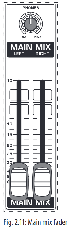
MAIN MIX
Use the high-precision quality faders to control the output level of the main mix.
MAIN OUT
The MAIN outputs carry the MAIN MIX signal and are on balanced XLR connectors with a nominal level of +4 dBu. Depending on how you wish to use your mixer and which gear you own, you can connect the following equipment:
Live PA systems:
A stereo dynamics processor (optional), stereo equalizer (optional) and the stereo power amplifier for full-range loud-speakers with passive crossovers.
If you wish to use multi-way loudspeaker systems without an integrated crossover, you have to use an active crossover and several power amplifiers. Often, limiters are already built into active crossovers (e.g. BEHRINGER SUPER-X PRO CX2310 and ULTRADRIVE PRO DCX2496). Active crossovers are implemented directly before the power amplifier, and they divide the frequency range into several segments that are first amplified in the amplifiers and then passed onto the corresponding loudspeakers.
Recording:
For mastering, using a stereo compressor such as the COMPOSER PRO-XL MDX2600 can be recommended. Use it to custom-tailor the dynamic characteristics of your signal to the dynamic range of the recording equipment you are using. The signal is in this case passed on from the compressor into the recorder.
PHONES
The PHONES control adjusts the volume of the headphones connected to the PHONS/CTRL connector. If you connect active monitors or an amplifier, use this connector to adjust the output signal level.
- We would like to draw your attention to the fact that extreme volumes may damage your hearing and/or your headphones or loudspeakers. Turn the MAIN MIX faders and the PHONES control in the main section fully down before you switch on the unit. Always be careful to set the appropriate volume.

PHONS/CTRL connector
You can connect headphones to this ¼» TRS connector. The connector can also be used for feeding active monitor loudspeakers (or an amplifier) in your control room. For this purpose, the signal is taken directly before it is passed on to the main mix faders.
Level meter and level setting
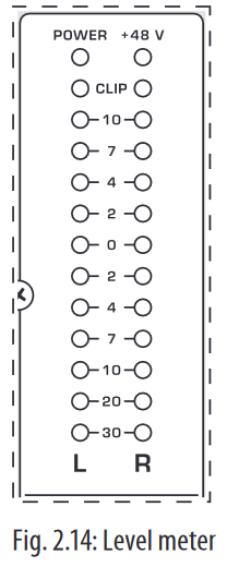
POWER
The blue POWER LED indicates that the device is switched on.
+48 V
The red «+48 V» LED lights up when the phantom power supply is switched on. The phantom power supply is necessary for condenser microphones and is activated using the corresponding switch on the rear of the device.
- Connect microphones before you switch on the phantom power supply. Please do not connect microphones to the mixer (or the stagebox/wallbox) while the phantom power supply is switched on. In addition, the monitor/PA loudspeakers should be muted before you activate the phantom power supply. After switching on, wait approx. one minute to allow for system stabilization.
LEVEL METER/CLIP
The high-precision level meter accurately displays the appropriate signal level.
LEVEL SETTING:
When recording to a digital device, the recorder’s peak meter should not exceed 0 dB. This is because, unlike analog recordings, slightly excessive levels can create unpleasant digital distortion.
When recording to an analog device, the VU meters of the recording machine should reach approx. +3 dB with low-frequency signals (e.g. kick drum). Due to their inertia VU meters tend to display too low a signal level at frequencies above 1 kHz. This is why, for example, a Hi-Hat should only be driven as far as -10 dB. Snare drums should be driven to approx. 0 dB.
- The peak meters of your XENYX display the level virtually independent of frequency. A recording level of 0 dB is recommended for all signal types.
USB input/output

The XENYX mixer line has built-in USB connectivity, allowing stereo signals to be sent to and from the mixer and a computer. The audio sent from the mixer to a computer is identical to the MAIN MIX. Audio being sent to the mixer from a computer can be routed to the main mix with the 2-TR/USB TO MAIN button.
Connect the USB type B plug into the USB jack on the mixer, and the other end into a free USB port on your computer. There are no required drivers, but we recommend that PC users install the included ASIO driver. The driver can also be downloaded from behringer.com.
Graphic 7-band equalizer

The graphic stereo equalizer allows you to tailor the sound to the room acoustics.
FBQ FEEDBACK DETECTION
The switch turns on the FBQ Feedback Detection System. It uses the LEDs in the frequency band faders to indicate the critical frequencies. On a per-need basis, lower the frequency range in question somewhat in order to avoid feedback. The graphic stereo equalizer has to be turned on in order to use this function.
- Logically, at least one (ideally several) microphone channels have to be open for feedback to occur at all!
Feedback is particularly common when stage monitors («wedges») are concerned, because monitors project sound in the direction of microphones. Therefore, you can also use the FBQ Feedback Detection for monitors by placing the equalizer in the monitor bus (see MAIN MIX/MONITOR).
EQ IN
Use this switch to activate the graphic equalizer. When activated, the fader LEDs will illuminate.
MAIN MIX/MONITOR
This toggles the graphic equalizer between the main mix and the monitor mix. With the switch up (not depressed), the equalizer is active in stereo on the main mix, and inactive on the monitor mix.
When the switch is depressed the equalizer is active in mono on the monitor mix, and inactive on the main mix.
Rear view of X1222USB

FUSE HOLDER/IEC MAINS RECEPTACLE
The console is connected to the mains via the cable supplied, which meets the required safety standards. Blown fuses must only be replaced by fuses of the same type and rating. The mains connection is made via a cable with IEC mains connector. An appropriate mains cable is supplied with the equipment.
POWER
Use the POWER switch to power up the mixing console. The POWER switch should always be in the «Off» position when you are about to connect your unit to the mains.
To disconnect the unit from the mains, pull out the main cord plug. When installing the product, ensure that the plug is easily accessible. If mounting in a rack, ensure that the mains can be easily disconnected by a plug pull or by an all-pole disconnect switch on or near the rack.
Attention: The POWER switch does not fully disconnect the unit from the mains. Unplug the power cord completely when the unit is not used for prolonged periods of time.
PHANTOM
The PHANTOM switch activates the phantom power supply for the XLR microphone inputs, which is required to operate condenser microphones. The red +48 V LED lights up when phantom power is on. As a rule, dynamic microphones can still be used with phantom power switched on, provided that they are wired in a balanced configuration. In case of doubt, contact the microphone manufacturer!
- Connect microphones before you switch on the phantom power supply. Please do not connect microphones to the mixer (or the stagebox/ wallbox) while the phantom power supply is switched on. In addition, the monitor/PA loudspeakers should be muted before you activate the phantom power supply. After switching on, wait approx. one minute to allow for system stabilization.
You must never use unbalanced XLR connectors (PIN 1 and 3 connected) on the MIC input connectors if you want to use the phantom power supply.
SERIAL NUMBER
Please note the important information on the serial number.
Digital Effects Processor and XPQ Surround Function
Digital effects processor

24-BIT MULTI-EFFECTS PROCESSOR
Here you can find a list of all presets stored in the multi-effects processor. This built-in effects module produces high-grade standard effects such as reverb, chorus, flanger, delay and various combination effects. The integrated effects module has the advantage of requiring no wiring. This way, the danger of creating ground loops or uneven signal levels is eliminated at the outset, completely simplifying the handling.
These effect presets are designed to be added to dry signals. If you move the FX TO MAIN control, you mix the channel signal (dry) and the effect signal.
This also goes for mixing effects signals with the monitor mix. The main difference is that the mix ratio is adjusted using the FX TO MON control. Of course, a signal has to be fed into the effects processor via the FX control in the channel strip for both applications.
FOOTSWITCH
Connect a standard footswitch to the footswitch connector; use this to switch the effects processor on and off. A flashing dot at the bottom of the display indicates if the effects processor is muted via the footswitch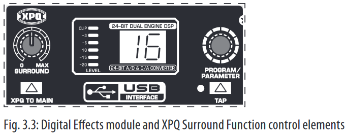
LEVEL
The LED level meter on the effects module should display a sufficiently high level. Take care to ensure that the clip LED only lights up at peak levels. If it is lit constantly, you are overloading the effects processor and this could cause unpleasant distortion. The FX SEND fader determines the level that reaches the effects module.
PROGRAM
You can select the effect preset by turning the PROGRAM control. The display flashes the number of the current preset. To recall the selected preset, press the button; the flashing stops. You can also recall the selected preset using the footswitch.
XPQ surround function
The surround function can be enabled/disabled with the XPQ TO MAIN switch. This is a built-in effect that widens the stereo width, thus making the sound more lively and transparent. Use the SURROUND control to determine the intensity of this effect.
Installation
Rack mounting
The packaging of your mixing console contains two 19″ rack mount brackets which can be installed on the side panels of the console.
Before you can attach the rack mount brackets to the mixing console, you need to remove the screws holding the left and right side panels. Use these screws to fasten the two brackets onto the console, being careful to note that each bracket fits a specific side. With the rack mount brackets installed, you can mount the mixing console in a commercially available 19″ rack. Be sure to allow for proper air flow around the unit, and do not place the mixing console close to radiators or power amps, so as to avoid overheating.
- Only use the screws holding the mixing console side panels to fasten the 19″ rack mounts.
Cable connections
You will need a large number of cables for the various connections to and from the console. The following illustrations show the wiring of these cables. Be sure to use only high-grade cables.
Audio connections
Please use commercial RCA cables to wire the 2-track inputs and outputs.
You can, of course, also connect unbalanced devices to the balanced input/ outputs. Use either mono plugs, or ensure that ring and sleeve are bridged inside the stereo plug (or pins 1 & 3 in the case of XLR connectors).
You must never use unbalanced XLR connectors (pins 1 and 3 connected) on the MIC inputs if you intend to use the phantom power supply.


Specifications
| Mono Inputs | |
| Microphone Inputs (XENYX Mic Preamp) | |
| Type | XLR, electronically balanced, discrete input circuitry |
| Mic E.I.N. (20 Hz — 20 kHz) | |
| @ 0 Ω source resistance | -134 dB / 135.7 dB A-weighted |
| @ 50 Ω source resistance | -131 dB / 133.5 dB A-weighted |
| @ 150 Ω source resistance | -129 dB / 130.5 dB A-weighted |
| Frequency response | <10 Hz — 150 kHz (-1 dB), <10 Hz — 200 kHz (-3 dB) |
| Gain range | +10 to +60 dB |
| Max. input level | +12 dBu @ +10 dB Gain |
| Impedance | approx. 2.6 k Ω balanced |
| Signal-to-noise ratio | 110 dB / 112 dB A-weighted (0 dBu In @ +22 dB Gain) |
| Distortion (THD + N) | 0.005% / 0.004% A-weighted |
| Line Input | |
| Type | ¼» TRS connector, electronically balanced |
| Impedance | approx. 20 kΩ balanced approx. 10 kΩ unbalanced |
| Gain range | -10 to +40 dB |
| Max. input level | +22 dBu @ 0 dB Gain |
| Fade-Out Attenuation (Crosstalk Attenuation) | |
| Main fader closed | 98 dB |
| Channel muted | 85 dB |
| Channel fader muted | 85 dB |
| Frequency Response | |
| Microphone input to main out | |
| <10 Hz — 90 kHz | +0 dB / -1 dB |
| <10 Hz — 160 kHz | +0 dB / -3 dB |
| Stereo Inputs | |
| Channels 5/6, 7/8 | |
| Microphone input | |
| Type | XLR microphone connector, electronically balanced |
| Impedance | approx. 2.6 k Ω balanced |
| Gain range | 0 dB to +40 dB |
| Max. input level | +2 dBu |
| Channels 9/10, 11/12 | |
| Stereo line inputs | |
| Type | 2 x ¼» TRS connector, unbalanced |
| Impedance | approx. 40 kΩ @ 0 dB Gain |
| Gain range | -20 dB to +20 dB |
| Max. input level | +22 dBu @ 0 dB Gain |
| CD/Tape In | |
| Type | RCA connectors |
| Impedance | approx. 10 kΩ |
| Max. input level | +22 dBu |
| EQ Mono Channels | |
| Low | 80 Hz / ±15 dB |
| Mid | 2.5 kHz / ±15 dB |
| High | 12 kHz / ±15 dB |
| Low cut | 80 Hz, 18 dB/oct. |
| EQ Stereo Channels | |
| Low | 80 Hz / ±15 dB |
| Mid | 2.5 kHz / ±15 dB |
| High | 12 kHz / ±15 dB |
| MON/FX Send | |
| Type | ¼» TS connector, unbalanced |
| Impedance | approx. 120 Ω |
| Max. output level | +22 dBu |
| Aux Returns | |
| Type | ¼» TRS connector, unbalanced |
| Impedance | approx. 10 k Ω |
| Max. input level | +22 dBu |
| Main Outputs | |
| Type | XLR, electronically balanced |
| Impedance | approx. 240 Ω balanced approx. 120 Ω unbalanced |
| Max. output level | +28 dBu |
| Headphone Output | |
| Type | ¼» TRS connector, unbalanced |
| Max. output level | +19 dBu / 150 Ω (+25 dBm) |
| CD/Tape Out | |
| Type | RCA connectors |
| Impedance | approx. 1 kΩ |
| Max. output level | +22 dBu |
| DSP | Texas Instruments |
| Converter | 24-bit Sigma-Delta 64/128-times oversampling |
| Sampling rate | 40 kHz |
| USB | |
| Audio | Stereo In/Out |
| Connector | Type B |
| Converter | 16-bit |
| Sample Rate | 48 kHz |
| Main Mix System Data | |
| Noise | |
| Main mix @ -∞, Channel fader -∞ |
-99 dB -101 dB A-weighted |
| Main mix @ 0 dB, Channel fader -∞ |
-84 dB -87 dB A-weighted |
| Main mix @ 0 dB, Channel fader @ 0 dB |
-80 dB -82 dB A-weighted |
| Power Supply | |
| Mains Voltage | 100 — 240 V~, 50 — 60 Hz |
| Power consumption | 40 W |
| Fuse | T 1.6 A H 250 V |
| Mains connection | Standard IEC receptacle |
| Physical | |
| Dimensions (H x W x D) | approx. 3 7/8 x 13 18/32 x 13 5/32″ approx. 97 x 345 x 334 mm |
| Weight (net) | approx. 8.38 lbs. approx. 3.80 kg |
Measuring conditions:
- 1 kHz rel. to 0 dBu; 20 Hz — 20 kHz; line input; main output; unity gain.
- 20 Hz — 20kHz; measured at main output. Channels 1 — 4 unity gain; EQ flat; all channels on main mix; channels 1/3 as far left as possible, channels 2/4 as far right as possible. Reference = +6 dBu.
BEHRINGER is constantly striving to manintain the highest professional standards. As a result of these efforts, modifications may be made from time to time to existing products without prior notice. Specifications and appearance may differ from those listed or illustrated.
Here you can download full pdf version of manual, it may contain additional safety instructions, warranty information, FCC rules, etc.
 10:37
10:37
Behringer Virtualizer: Standard and PRO. Big difference!
 03:37
03:37
BEHRINGER VIRTUALIZER PRO DSP2024P
 15:12
15:12
How to use behringer virtualizer pro dsp2024p effects processor
 26:39
26:39
BEHRINGER FX2000 Virtualizer 3D Multi-Effect Processor — FULL Tutorial & Demo
 06:25
06:25
Behringer DSP2024P 24-Bit Virtualizer Pro Effects Processor Midi Control
 04:08
04:08
Behringer dsp2024p и Korg nanokontrol
 08:24
08:24
Behringer Virtualizer Pro DSP2024P Yamaha FB-01 Roland UA-100 Superteclados.com
 04:34
04:34
PROCESADOR DE VOCES DSP2024 PROGRAMACION PARTE 1
Процессор мульти-эффектов
Руководство
по эксплуатации
Версия 1.1 Февраль 2002 г

Меры безопасности, Предостережение: во избежание поражения эл, Внимание: во избежание пожара или поражения
Процессор мульти-эффектов behringer dsp 2024
- Изображение
- Текст
Процессор мульти-эффектов Behringer DSP 2024
2003 I.S.P.A. – Engineering, перевод
МЕРЫ БЕЗОПАСНОСТИ
ПРЕДОСТЕРЕЖЕНИЕ:
Во избежание поражения электротоком не снимайте
кожух (заднюю стенку) прибора. Внутри корпуса
отсутствуют какие-либо регулировки, доступные пользователю. Обслуживание изделия
должно осуществляться квалифицированным специалистом. Во избежание поражения
электротоком не подвергайте аппарат воздействию дождя или влаги.
ВНИМАНИЕ:
Во избежание пожара или поражения электротоком не подвергайте устройство
воздействия влаги и не выставляйте его под дождь!
Данный символ, вне зависимости от того,
где он изображен, предупреждает о
необходимости обращения к данному
Руководству по эксплуатации. Перед
началом
эксплуатации
внимательно
изучите Руководство.
Данный символ, вне зависимости от того,
где он изображен, предупреждает о
наличии опасного напряжения внутри
корпуса прибора
Перед началом эксплуатации внимательно изучите все указания по безопасности и настоящее Руководство.
ПОДРОБНЫЕ ИНСТРУКЦИИ ПО БЕЗОПАСНОСТИ:
Необходимо строго соблюдать все инструкции, приведенные в данном Руководстве.
Вода и влага:
Запрещается эксплуатация POWERPLAY PRO вблизи воды (например, около раковин, моек, емкостей для стирки, в сырых
подвальных помещениях или вблизи плавательных бассейнов).
Вентиляция:
POWERPLAY PRO следует устанавливать таким образом, чтобы обеспечить надлежащую естественную вентиляцию.
Запрещается устанавливать аппарат на диваны, прикроватные коврики или тому подобные поверхности – это может
привести к блокированию вентиляционных отверстий. Запрещается устанавливать POWERPLAY PRO в мебельные ниши,
книжные шкафы или на полки в условиях, не обеспечивающих надлежащую вентиляцию.
Источники тепла:
POWERPLAY PRO должен располагаться вдали от источников тепла — радиаторов, отопительных батарей, кухонных плит
или иных приборов, (включая усилители мощности), для которых характерно выделение тепла.
Электропитание:
POWERPLAY PRO следует подключать к электрической сети с напряжением и частотой, указанными в Руководстве или на
корпусе прибора.
Заземление:
Необходимо принять меры к обеспечению сохранности заземления.
Защита сетевого шнура:
Сетевой шнур должен быть проложен таким образом, чтобы исключить хождение по нему или возможность перегибов и/или
защемления посторонними предметами. Особое внимание следует обратить на состояние шнура питания, а также его
разъема, в точке подключения к устройству.
Чистка:
Устройство следует чистить исключительно средствами, рекомендованными изготовителем.
Перерывы в эксплуатации:
При длительных перерывах в эксплуатации необходимо вынуть вилку шнура из сетевой розетки.
Попадание внутрь посторонних предметов и жидкостей:
Необходимо соблюдать осторожность, чтобы не допустить попадания через отверстия внутрь корпуса прибора посторонних
предметов и жидкостей.
Повреждения, требующие квалифицированного вмешательства:
Прибор должен быть направлен на осмотр квалифицированными техническими специалистами в следующих случаях:
— повреждения шнура питания или вилки;
— попадания внутрь корпуса посторонних предметов или жидкостей;
— попадания прибора под дождь;
— нарушения нормальной эксплуатации или наличия признаков явного ухудшения технических характеристик;
—
падения прибора и/или повреждения его корпуса.
Техническое обслуживание:
Техническое обслуживание прибора пользователем должно осуществляться исключительно в пределах, оговоренных в
Руководстве по эксплуатации. Во всех иных случаях обслуживание изделия должно поручаться квалифицированным
техническим специалистам.
2

Процессор мульти-эффектов Behringer DSP 2024
2003 I.S.P.A. – Engineering, перевод
ВСТУПЛЕНИЕ
Уважаемый пользователь!
Добро пожаловать в команду пользователей VIRTUALIZER PRO. Спасибо за оказанное нам
доверие.
Написание этого предисловия – в высшей степени приятная задача. После нескольких месяцев
мозговой атаки и дальнейшей реализации поставленных задач, наши инженеры достигли цели:
значительного улучшения прекрасного прибора. Наш VIRTUALIZER уже давно считается
стандартным оборудованием многочисленных студий и Р.А.-систем. Как с любым новым
продуктом, разработка нового VIRTUALIZER PRO означает также и большой груз
ответственности. На всех стадиях разработки и воплощения идей мы ни на секунду не
забываем про Вас – конечного пользователя и музыканта, о Ваших требованиях и пожеланиях.
Чтобы соответствовать Вашим профессиональным ожиданиям, нам пришлось приложить
немало усилий. Разработка нового изделия всегда объединяет вместе множество людей, и
замечательно, когда все участники могут по праву гордиться результатами.
Для нашей компании очень важно делить радость с Вами, поскольку Вы – самый главный член
команды BEHRINGER. Ваши высококвалифицированные предложения и пожелания внесли
немалый вклад в успешное развитие нашей компании. В свою очередь, мы отвечаем
устойчивым качеством и надежностью наших приборов (производящихся согласно
сертифицированной системе управления ISO9000), прекрасными техническими и аудио
характеристиками и вполне доступными ценами. Мы надеемся, что это позволит Вам
полностью раскрыть свои творческие способности, невзирая на возможные финансовые
ограничения.
Нам часто задают вопрос, как нам удается выпускать такие высококлассные приборы по таким
низким ценам. Ответ весьма прост: благодаря Вам, нашим покупателям! Большое число
удовлетворенных покупателей означает большие объемы продаж, что, в свою очередь,
позволяет нам снизить производственные и логистические издержки. Так что, в конечном
счете, Ваш успех – это и наш успех!
Мне хотелось бы выразить благодарность всем, кто принимал участие в нашем проекте
VIRTUALIZER PRO. Каждый из этих людей внес личный вклад в создание этого прибора, —
наши инженеры, дизайнеры, многочисленные сотрудники компании и, наконец, и Вы,
пользователь BEHRINGER.
Друзья, овчинка стоила выделки!
Спасибо,
Искренне Ваш,
Ули Берингер,
Президент Behringer Spezielle Studiotechnik GmbH
3

Высокопроизводительный 24-битовый процессор муль, Virtualizer
Страница 4
- Изображение
- Текст
Процессор мульти-эффектов Behringer DSP 2024
2003 I.S.P.A. – Engineering, перевод
VIRTUALIZER
®
PRO
Высокопроизводительный 24-битовый процессор мульти-
эффектов с двумя «машинами» обработки
▲ 71 новый алгоритм обработки, большинство в истинном стерео
▲ Адаптивные алгоритмы VIRTUAL ROOM, позволяющие создавать
исключительно естественную реверберацию и задержку
▲ Замечательные алгоритмы модуляции, динамической и
психоакустической обработки, эквализации
▲ Алгоритмы имитации моделей усилителей, дисторшн и
специальные эффекты
▲ 11 комбинаций эффектов с переключаемой
последовательной/параллельной конфигурацией
▲ В одном эффекте – до 7 регулируемых параметров плюс эквализация
по НЧ и ВЧ
▲ 24-битовые АЦП и ЦАП с 64/128-кратной передискретизацией
▲ Истинно стереофоническая обработка, обеспечивающая
реалистичное разделение каналов в стереофоническом звуковом
поле
▲ 24-битовая внутренняя обработка сигнала, профессиональная
частота дискретизации 46 кГц
▲ 100 фабричных пресетов, 100 пользовательских пресетов
▲ Расширенная MIDI-спецификация
▲ Точные 8-сегментные светодиодные индикаторы уровня
▲ Встроенный блок питания, соответствующий требованиям к
профессиональной работе
▲ Серво-балансные входы и выходы на разъемах XLR и ¼″ TRS
▲ Производится в соответствии с системой сертификации ISO9000
4

Процессор мульти-эффектов Behringer DSP 2024
2003 I.S.P.A. – Engineering, перевод
СОДЕРЖАНИЕ
1. ВВЕДЕНИЕ
6
1.1 Концепция
1.2 Прежде, чем начать
1.3 Элементы управления
6
7
7
2. АЛГОРИТМЫ ЭФФЕКТОВ
10
2.1 Алгоритмы реверберации (Reverb)
2.2 Алгоритмы задержки (Delay)
2.3 Эффекты модуляции (Modulation) и сдвига тона (Pitch Shifter)
2.4 Динамические (Dynamics) эффекты
2.5 Психоакустические (Psycho Acoustics) эффекты
2.6 Эффекты фильтров/эквализации (Filter/EQ)
2.7 Эффекты искажения и симуляции усиления (Distortion/Amp Simulation)
2.8 Специальные эффекты (Special FX)
2.9 Комбинации алгоритмов эффектов (программы мультиэффектов)
11
11
12
13
14
15
16
17
18
3. УПРАВЛЕНИЕ
20
3.1 Структура эффектов
3.2 Вызов пресетов
3.3 Редактирование программ (режим редактирования)
3.4 Сохранение программ
3.5 Сравнение отредактированного пресета с исходным фабричным пресетом
(функция COMPARE)
3.6 Режим SETUP
3.6.1 Управление MIDI
3.6.2 Режим INPUT
3.6.3 Режим OUTPUT
3.6.4 Конфигурация двух движков (CONFIG)
3.7 Восстановление фабричных пресетов
20
23
23
23
24
24
24
25
25
25
25
4. ПРИЛОЖЕНИЯ
26
4.1 Использование VIRTUALIZER PRO в MIDI-установке
4.2 Использование VIRTUALIZER PRO с шиной Aux
4.3 Использование VIRTUALIZER PRO в цепи разрыва
4.4 Использование VIRTUALIZER PRO как устройства эффектов для инструментов
4.5 Использование VIRTUALIZER PRO в MIDI-установке
26
26
27
27
29
5. MIDI-ФУНКЦИИ DSP2024P
29
5.1 Сохранение данных при помощи MIDI
29
6. ИНСТАЛЛЯЦИЯ
30
6.1 Подключение к электросети
6.2 Звуковые разъемы
6.3 MIDI-разъемы
6.4 Выбор рабочего уровня
30
30
31
31
7. ПРИЛОЖЕНИЕ
32
7.1 Обзор параметров
7.2 Функции MIDI
7.3 Установки по умолчанию
7.4 Диапазон параметров алгоритмов эффектов
32
34
35
37
8. ТЕХНИЧЕСКИЕ ХАРАКТЕРИСТИКИ
39
9. ГАРАНТИЯ
40
5

Процессор мульти-эффектов Behringer DSP 2024
2003 I.S.P.A. – Engineering, перевод
1. ПРЕДИСЛОВИЕ
Вы стали обладателем BEHRINGER VIRTUALIZER PRO, мощного процессора мульти-эффектов,
обеспечивающего первоклассные эффекты реверберации и ряд других алгоритмов. В DSP2024P
имеется 71 новых эффектов, пользоваться которыми, благодаря логически структурированному
пользовательскому интерфейсу, легко и просто.
Чтобы воспроизвести естественную реверберацию, фирма BEHRINGER разработала новые виды
алгоритмов виртуальной акустики. Эти алгоритмы помогут Вам рассчитать все пространственные и
реверберационные параметры с абсолютно профессиональным качеством и естественностью.
Несмотря на гигантский объем вычислений, выполняемый 24-битным процессором DSP2024P,
VIRTUALIZER PRO очень прост в обращении. Легко меняются те или иные параметры, необходимые для
достижения специфического звучания. Вы можете сохранять свои программы в 100 пользовательских
пресетах.
DSP2024P снабжен прекрасными алгоритмами реверберации и задержки, но это еще не все. Кроме
симуляции классических листовых ревербераторов, VIRTUALIZER PRO поразит Вас замечательными
эффектами модуляции (такими, как хорус, флэнжер и фазер), включающими их особые разновидности –
сдвиг тона, тремоло, симуляция вращающегося громкоговорителя. Динамические и психоакустические
эффекты DSP2024P позволяют обойтись без множества дополнительных приборов. DSP2024P снабжен
также рядом эффектов искажения и усиления, сочетающимися с симуляцией акустической системы. Так
что, к примеру, если Вы записываете гитарную партию, Вы можете добиться превосходного звучания на
ленте или жестком диске, даже без использования акустической системы и гитарного усилителя.
Параметры эффектов очень легко редактировать. DSP2024P позволяет редактировать до 7 параметров
пресета, настраивая эффект в соответствии с Вашими требованиями. В сочетании с редактируемыми
НЧ- и ВЧ-фильтрами, в целом образуется до 9 редактируемых параметров для каждого эффекта! Они
могут быть прямым образом выбраны и сохранены в 100 пользовательских пресетах. Таким образом, Вы
можете добиться соответствия звуковых характеристик Ваших пресетов характеристикам помещения,
что экономит время при беспокойных концертных выступлениях. Помимо логического и простого
управления, впечатляют также технические характеристики VIRTUALIZER PRO. Следующие
особенности обеспечивают обработку сигнала на профессиональном уровне:
▲ Чрезвычайно точные 24-битные АЦ- и ЦА-преобразователи.
▲ Профессиональная частота дискретизации обеспечивает высокое разрешение сигнала в
частотном диапазоне от 20 Гц от 20 кГц.
▲ 24-битный процессор с двумя независимыми движками обработки входного звукового
сигнала.
▲ Как и у всех продуктов фирмы BEHRINGER, высочайшее качество компонентов и сборки.
DSP2024P может использоваться практически в любой MIDI-установке. Кроме того, Вы можете
использовать MIDI для программирования VIRTUALIZER PRO при помощи программы редактирования
на Вашем компьютере. DSP2024P может также посылать системные (Sys-Ex ) данные и данные
контроллеров, благодаря чему Вы можете переносить все пресеты и установки на секвенсер при
помощи сброса системных данных (Sys-Ex Dump). При необходимости Вы можете загрузить эти
установки, переслав системные данные с Вашего секвенсера обратно на DSP2024P.
)
В начале руководства описывается применяемая терминология, благодаря чему Вы сможете
полностью понять функции VIRTUALIZER PRO. Пожалуйста, внимательно изучите данное
руководство и сохраните его для дальнейших справок.
1.1
Концепция
Фирма BEHRINGER всегда чрезвычайно тщательно подбирает компоненты. Сердце BEHRINGER
VIRTUALIZER PRO – 24-битный цифровой сигнальный процессор, благодаря своим выдающимся
техническим характеристикам считающийся одним из лучших в своем классе. Первоклассные 24-битные
АЦ- и ЦА-преобразователи гарантируют точное преобразование звуковых сигналов. Жесткие диапазоны
допусков для конденсаторов и резисторов, высококачественные переключатели и другие отборные
компоненты обеспечивают высокую точность и надежную работу прибора.
VIRTUALIZER PRO производится на основе технологии SMD (Surface Mount Device, поверхностный
монтаж на печатную плату). Использование сверхминиатюрных компоновочных блоков дает не только
возможность крайне плотного размещения, но также обеспечивает повышенную функциональную
надежность. DSP2024P производится согласно сертифицированной системе управления ISO9000
6
Процессор мульти-эффектов Behringer DSP 2024
2003 I.S.P.A. – Engineering, перевод
1.2 Прежде, чем начать
Ваш VIRTUALIZER PRO тщательно упакован на фабрике так, чтобы защитить прибор от грубого
обращения. Тем не менее мы рекомендуем Вам тщательно осмотреть коробку и ее содержимое на
предмет физических повреждений, могущих случиться при транспортировке.
)
Если прибор поврежден, немедленно известите Вашего дилера, в противном случае Ваши
претензии могут быть не удовлетворены.
Для монтажа BEHRINGER VIRTUALIZER PRO требуется пространство высотой 1U (1¾ дюйма) в 19-
дюймовом рэке. При установке, пожалуйста, оставьте глубину 4 дюйма для подключения к задней
панели прибора.
Убедитесь, что вокруг прибора достаточно воздушного пространства для охлаждения. Пожалуйста, не
размещайте VIRTUALIZER PRO на высокотемпературных устройствах, например, усилителях мощности,
во избежание перегрева.
)
Перед подключением VIRTUALIZER PRO к сети, тщательно проверьте правильную установку
напряжения прибора:
Плавкий предохранитель в сетевом гнезде снабжен 3 треугольными отметками, 2 из которых
противоположны друг другу. VIRTUALIZER PRO установлен на рабочее напряжение, указанное рядом с
данными отметками, и может быть установлен на другое напряжение при помощи поворота
предохранителя на 180
0
. ВНИМАНИЕ: Эта инструкция не относится к специальным экспортным
моделям, например, разработанным для напряжения 115 В!
Подключение к электросети осуществляется при помощи сетевого кабеля и штепсельной розетки IEC,
соответствующей установленным нормам безопасности.
)
Обратите внимание на правильное заземление прибора. Для собственной безопасности не
удаляйте разъемы заземления из электрических приборов или сетевых шнуров.
)
Инсталляция
и
работа
с
данным
прибором
должны
выполняться
только
квалифицированным персоналом. И до, и после инсталляции персонал, использующий прибор,
должен убедиться в его надлежащем заземлении – в противном случае электростатический
разряд может привести к ухудшению работы прибора. Подробнее см. глава 6, «ИНСТАЛЛЯЦИЯ».
BEHRINGER VIRTUALIZER PRO оборудован автоматически симметричными входами и выходами.
Электронная схема снабжена автоматическим подавлением фона для симметричных сигналов,
обеспечивая прекрасную работу даже на самых высоких уровнях. Успешно подавляются внешние
наводки, фон сети переменного тока и т.п. Автоматическая вспомогательная функция обнаруживает
несимметричное подключение и автоматически компенсирует уровень во избежание разницы уровней
входных и выходных сигналов (коррекция 6 дБ).
MIDI-разъемы (IN/OUT/THRU) — стандартные 5-контактные разъемы DIN. Передача данных изолирована
от земли при помощи оптронов.
1.3
Элементы управления
Рис. 1.1: Лицевая панель VIRTUALIZER PRO
На лицевой панели VIRTUALIZER PRO расположены пять регуляторов редактирования (кодеки
непрерывного вращения), крупный ступенчатый кодек, шесть кнопок параметров, светодиодный дисплей
и сетевой переключатель. Для мониторинга параметров каждого из двух полностью независимых
каналов служит 8-разрядный светодиодный индикатор.
7

Процессор мульти-эффектов Behringer DSP 2024
2003 I.S.P.A. – Engineering, перевод
Рис. 1.2: Дисплей VIRTUALIZER PRO
1 Обе строки СВЕТОДИОДНЫХ ИНДИКАТОРОВ отображают интенсивность входного сигнала в дБ
относительно номинального уровня, который устанавливается на задней панели при помощи
переключателя OPERATING LEVEL.
2 После включения электропитания на СВЕТОДИОДНОМ ДИСПЛЕЕ отобразится название последнего
используемого эффекта. При редактировании на СВЕТОДИОДНОМ ДИСПЛЕЕ отображается название
параметра, а на 4-значном буквенно-цифровом дисплее – абсолютное значение параметра.
3 Справа от СВЕТОДИОДНОГО ДИСПЛЕЯ расположены четыре СВЕТОДИОДНЫХ ИНДИКАТОРА
СТАТУСА, указывающих тип параметра, с которым Вы работаете. Можно выполнить следующие
действия:
Установить абсолютное значение параметра эффекта («%»)
►
►
►
►
Увеличить или уменьшить амплитуду или задать порог срабатывания компрессора («dB»)
Изменить частоту («Hz») или
Изменить параметр времени («sec»)
4 ИНДИКАТОРЫ ГРУПП АЛГОРИТМОВ указывают, к какой категории принадлежит выбранный эффект.
В DSP2024P имеется восемь различных групп алгоритмов.
Рис. 1.3: Функциональные кнопки, регуляторы и ступенчатый кодек
5 Каждый пресет DSP2024P имеет как минимум четыре редактируемых параметра. СВЕТОДИОДНЫЕ
ИНДИКАТОРЫ
РЕДАКТИРОВАНИЯ
указывают,
какие
параметры
регулируются
четырьмя
РЕГУЛЯТОРАМИ РЕДАКТИРОВАНИЯ. Если горит верхний светодиодный индикатор, 6 регулирует
параметр EDIT A, 7 регулирует параметр EDIT B, 8 меняет параметр EDIT C и 9 – параметр EDIT D.
Если горит средний СВЕТОДИОДНЫЙ ИНДИКАТОР РЕДАКТИРОВАНИЯ, четыре регулятора изменяют
параметры, указанные слева и справа. Аналогично и назначение нижнего СВЕТОДИОДНОГО
ИНДИКАТОРА РЕДАКТИРОВАНИЯ.
)
Точное значение отдельных параметров эффектов дается в главе 7.1
8

Процессор мульти-эффектов Behringer DSP 2024
2003 I.S.P.A. – Engineering, перевод
6 ПЕРВАЯ РУЧКА EDIT (непрерывный вращающийся кодек) изменяет значения первого (EDIT A) и
пятого (EDIT E) параметров эффекта. Он служит также для выбора MIDI-функций (MIDI). Для
переключения от EDIT A к EDIT E и наоборот нажмите кнопку EDIT 13 . Для выбора MIDI-функций
нажмите кнопку SETUP 16 .
7 ВТОРАЯ РУЧКА EDIT изменяет значения параметров эффекта EDIT B и EDIT F. Если Вы выбираете
параметр INPUT при помощи кнопку SETUP 16, вы можете задать монофонический или
стереофонический режим работы DSP2024P (подробнее см. глава 3.6.2).
8 ТРЕТИЙ РУЧКА EDIT изменяет значения параметров эффекта EDIT C, EQ LO и глобального
параметра OUTPUT (см. глава 3.6.3). Для выбора также служат клавиши EDIT и SETUP.
9 ЧЕТВЕРТЫЙ РУЧКА EDIT изменяет значения параметров эффекта EDIT D, EQ HI и глобального
параметра CONFIG (см. глава 3.6.4). Для выбора параметров служат клавиши EDIT и SETUP.
)
При редактировании Вы можете повернуть один из четырех ручек EDIT, чтобы увидеть на
дисплее краткое описание текущего активного параметра. Это поможет Вам узнать, например.
что EDIT A регулирует предварительную задержку для всех эффектов реверберации
VIRTUALIZER PRO. Спустя примерно одну секунду название стирается и на дисплее появляется
текущее значение параметра. Эта функция может быть использована только для регулятора,
который еще не был выбран.
10 Вращением ручки MIX/BYPASS задаются уровни эффектов большинства алгоритмов в диапазоне от
0 до 100%. При уровне 0% входной сигнал DSP2024P направляется на выходы без добавления каких-
либо эффектов (полностью «сухой» сигнал). При уровне 100% на выходы посылается только
обработанный сигнал (полностью «мокрый» сигнал).
)
Если Вы используете DSP2024P в дополнительной (Aux) шине микшерного пульта, всегда
устанавливайте значение этого параметра на 100%. При использовании DSP2024P с гитарным
усилителем (в последовательной петле эффектов) мы рекомендуем значения между 20 и 50%
(в зависимости от типа усилителя).
)
Обратите внимание, что для эффектов «parametric» и «graphic EQ» (параметрический и
графический эквалайзер) вращением РЕГУЛЯТОРА MIX/BYPASS осуществляется коррекция
чувствительности.
Для обхода (Bypass) эффектов DSP2024P нажмите ручку MIX/BYPASS. Это дает возможность сравнения
оригинального и обработанного сигналов. Для отмены режима обхода и возврата к выбранному эффекту
снова нажмите ручку MIX/BYPASS. Мигающий светодиод MIDI IN, расположенный ниже регулятора,
указывает на поступление MIDI-данных в порт MIDI IN.
)
РЕГУЛЯТОР MIX/BYPASS и РЕГУЛЯТОРЫ РЕДАКТИРОВАНИЯ EDIT обладают динамической
реакцией. Это означает, что в зависимости от скорости их вращения текущий параметр
изменяется шагами по 1, 2 3, или 10. Чем быстрее вращение, тем больше изменяется значение
параметра.
11 Для выбора пресета нажмите один раз кнопку PRESET, затем вращайте КОЛЕСО JOG 17 .
12 Для выбора одного из 71 основных алгоритмов эффектов нажмите один раз кнопку EFFECT, затем
вращайте колесо JOG. Информация о значениях параметров, установленных для основных
алгоритмов эффектов дается в главе 7.4.
13 Для выбора функции ручек EDIT (см. 6 – 9 ) нажмите кнопку EDIT.
14 Когда Вы изменяете пользовательский пресет, начинает мигать светодиодный индикатор клавиши
STORE. В DSP2024P содержится 100 пользовательских пресетов и 100 фабричных пресетов (см.
Таблицу пресетов). Для сохранения изменений нажмите кнопку STORE. Выберите ячейку (номер) для
сохранения при помощи колеса JOG и подтвердите выбор повторным нажатием клавиши STORE.
15 Если Вы изменили пресет и светодиодный индикатор клавиши STORE начал мигать, Вы можете
нажать кнопку COMPARE для временного восстановления исходных установок пресета. После этого
загружаются исходные установки, начинает мигать светодиодный индикатор клавиши COMPARE, и на
СВЕТОДИОДНОМ ДИСПЛЕЕ появляется надпись «COMP». Для возврата в режим редактирования
снова нажмите кнопку COMPARE.
16 Для входа в режим установки SETUP нажмите кнопку SETUP. В режиме установки SETUP Вы
получаете доступ к параметрам, перечисленным ниже четырех ручек EDIT. Более подробная
информация о режиме установки SETUP дается в главе 3.6.
9

Процессор мульти-эффектов Behringer DSP 2024
2003 I.S.P.A. – Engineering, перевод
17 Для изменения значения параметра вращайте колесо JOG. Для увеличения значения – по часовой
стрелке, для уменьшения значения – против часовой стрелки. Если не выбрана ни одна из функций
редактирования, Вы можете выбрать программу непосредственно при помощи колеса JOG. При этом
на СВЕТОДИОДНОМ ДИСПЛЕЕ загорится точка. Пока она горит, можно выбирать программу без того,
чтобы соответствующие установки были немедленно слышимы. Краткое подавление сигнала
означает, что при быстром выборе пресетов при помощи колеса JOG ни один пресет непосредственно
не активирован. Если колесо JOG не вращается более секунды, точка на СВЕТОДИОДНОМ ДИСПЛЕЕ
исчезает и загружается программа.
18 Для включения и выключения VIRTUALIZER PRO служит переключатель POWER.
Рис. 1.4: Задняя панель VIRTUALIZER PRO
19 ПЛАВКИЙ ПРЕДОХРАНИТЕЛЬ/ВЫБОР НАПРЯЖЕНИЯ. Перед включением DSP2024P в сеть
убедитесь, что установленное напряжение соответствует напряжению местной электросети. При замене
предохранителя необходимо всегда использовать тот же самый тип предохранителя. Плавкий
предохранитель может быть установлен в одну из двух позиций, что позволяет переключаться между
напряжением 230 В и 115 В. При работе с напряжением 115 В за пределами Европы необходимо
использовать более мощные предохранители. (Подробности см. глава 8, «Технические
характеристики»). Подключение к сети осуществляется при помощи сетевого кабеля, входящего в
комплект поставки, и штепсельной розетки IEC.
20 Для передачи MIDI-команд служат разъемы MIDI IN, MIDI OUT, MIDI THRU.
21 СЕРИЙНЫЙ НОМЕР. Пожалуйста, в течение 14 дней после покупки заполните и верните гарантийную
карточку. В противном случае Вы теряете право на расширенную гарантию. Вы можете также
зарегистрироваться на нашем веб-сайте
www.behringer.com
.
22 Симметричные ВЫХОДЫ (OUTPUT) DSP2024P – разъемы XLR и ¼″ TRS.
23 Для переключения между уровнями –10 dBV (уровень домашней записи) и +4dBu служит
ПЕРЕКЛЮЧАТЕЛЬ OPERATING LEVEL. При переключении показания индикаторов автоматически
изменяются относительно номинального уровня и VIRTUALIZER PRO действует в оптимальном рабочем
режиме.
24 Симметричные ВХОДЫ (INPUT) DSP2024P – разъемы XLR и ¼″ TRS.
2. АЛГОРИТМЫ ЭФФЕКТОВ
Все эффекты основаны на различных алгоритмах. Например, алгоритм эффекта реверберации
запрограммирован по-другому, чем алгоритм хоруса. У каждого эффекта имеется определенный
алгоритм, по которому обрабатывается входной цифровой сигнал. Обработка осуществляется
цифровым сигнальным процессором (DSP). После генерирования эффекта и микширования входного
сигнала, цифровой сигнал преобразуется в аналоговый при помощи ЦА-преобразователя.
В каждом пресете VIRTUALIZER PRO можно редактировать до семи параметров. Произведенные
изменения по-разному влияют на звук. Далее дается обзор различных алгоритмов эффектов DSP2024P.
10

Комментарии
8
EUROPOWER PMP2000 Руководство пользователя
(35)
При помощи выключателя POWER Вы включаете РМР2000.
Выключатель POWER должен находится в отключенном положении,
когда производится подключение устройства к сети.
◊
Имейте в виду: Выключатель POWER не полностью отключает
устройство от цепи электропитания. Поэтому при больших
перерывах в работе необходимо вынимать штекер из розетки.
(36)
Выход RIGHT/MONO MAIN микшера PMP2000 предназначен для
подключения правой акустической системы. При этом выключатель
(21)
должен находиться в верхнем положении. Если основной микс
монофонический (выключатель (21) в нижнем положении), то на
правую акустическую систему будет подаваться монофонический
сигнал основного микса.
◊
Сопротивление подключенных колонок должно составлять не
менее 4 Ом.
(37)
Разъём BRIDGE для акустических систем объединяет левый и
правый каналы стереосигнала в один моновыход, что имеет смысл
при целесообразности использования только одной акустической
системы. Для использования BRIDGE-выхода необходимо установить
переключатель (21) в положение “LEFT/RIGHT”.
◊
выходу BRIDGE разрешается подключать только одну колонку с
сопротивлением не менее 8 Ом
◊
Пожалуйста, имейте в виду, что передаваемая на акустические
систему в мостовом режиме (BRIDGE) мощность значительно
выше мощности, передаваемой в обычном режиме.
Перед подключением изучите данные на задней
стороне устройства.
◊
Пожалуйста, имейте в виду, что при использовании выхода
BRIDGE категорически запрещается использование подключений к
RIGHT/MONO MAIN и LEFT/MONITOR!
(38)
Выход LEFT/MONITOR микшера PMP2000 предназначен для
подключения правой акустической системы. При этом выключатель
(21)
должен находиться в верхнем положении. Если основной микс
монофонический (выключатель (21) в нижнем положении), то на
правую акустическую систему будет подаваться монофонический
сигнал основного микса.
◊
Сопротивление подключаемой к данному выходу акустической
системы должно составлять не менее 4 Ом.
◊
Для правильного в плане полярности подключения акустических
систем смотрите данные по расположению контактов (распиновке)
на обратной стороне изделия.
(39)
СЕРИЙНЫЙ НОМЕР.
3. Эффект-Процессор
24-BIT MULTI-FX PROCESSOR
Данный встроенный модуль предназначен для создания стандартных
высококачественных звуковых эффектов (холл, хор, эхо и другие),
а также различных комбинаций эффектов. При помощи FX-регуляторов
добавляются эффекты. Преимущество интегрированного модуля эффект-
процессора заключается в том, что отсутствуют кабельные соединения,
благодаря чему значительно упрощается работа с устройством, а также
отсутствуют дефекты звука (фоновые шумы, неравные уровни по
каналам). Говоря о данных предустановленных эффектах (пресетах),
можно вести речь о классических “примешанных эффектах”. При повороте
переключателя FX TO MAIN/MON возникает микс, состоящий из основного
(сухого) сигнала и добавляемого сигнала от эффект-процессора.
◊
При помощи FX-регулятора можно отсекать все сигналы,
которые Вы не хотите обрабатывать.
4. Инсталляция
4.1 Напряжение сети электропитания
Перед подключением микшера к сети электропитания убедитесь, что её
параметры соответствуют регламентированным. Если вы подключаете
устройство к нерегламентированной электросети, то необходимо
использовать соответствующие предохранители. Требуемые параметры
предохранителей представлены в разделе “Технические Характеристики”.
При замене предохранителей соблюдайте правило: типы заменяемого и
заменяющего предохранителей должны совпадать.
4.2 Подключение к сети электропитания
Подключение к сети осуществляется при помощи сетевого кабеля,
входящего в комплект поставки. Кабель соответствует требованиям
техники безопасности.
◊
Обязательно имейте в иду, что инсталляция и эксплуатация
устройства должны осуществляться только квалифицированными
специалистами. Во время и после инсталляции необходимо
обеспечить надёжное заземление, так статическое электричество
может повредить устройство.
4.3 Кабельные соединения
Концентрические входы и выходы BEHRINGER PMP2000 за исключением
симметричных монолинейных входов расположены в виде
несимметричных моноконцентрических гнезд. Само собой разумеется,
что вы можете эксплуатировать PMP2000 как с симметричными, так и с
несимметричными концентрическими штекерами. Магнитофонные входы
и выходы представлены в виде стереоконтролирующих контактов.
◊
Обязательно обратите внимание на то, что монтаж и обслуживание
прибора выполняются только специалистами. Во время и после
монтажа всегда следует следить за достаточным заземлением
выполняющего манипуляции лица (лиц), поскольку в противном
случае из-за электростатических разрядов и тому подобного может
быть причинен вред эксплуатационным характеристикам.
Главная » Берингер » Микрофонный предусилитель Behringeramps & Compressors Руководство по эксплуатации 24-битного мульти-FX процессора British EQs и аудиоинтерфейса USB
 report this ad
Микрофон Preamps & Compressors 24-битный мультиэффектный процессор British EQs и аудиоинтерфейс USB
Документы / Ресурсы
Рекомендации

Музыкальное племя
Похожие сообщения


2
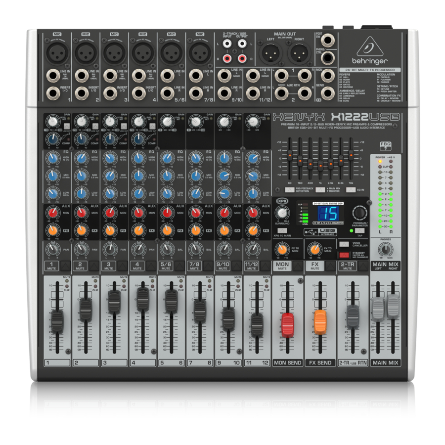
XENYX 1222FX
1222FX
XENYX
Premium 16-Input 2/2-Bus Mixer with XENYX Mic Preamps, British EQs,
24-Bit Multi-FX Processor and USB/Audio Interface
s Premium ultra low-noise, high headroom analog mixer
s 4 state-of-the-art XENYX Mic Preamps comparable to standalone boutique preamps
s Neo-classic British 3-band EQs for warm and musical sound
s Studio-grade 24-bit stereo FX processor with 100 awesome presets including reverb, chorus, flanger,
delay, pitch shifter and various multi-effects
s USB/Audio Interface included to connect directly to your computer
s 7-band stereo graphic EQ allows precise frequency correction of monitor or main mixes
s Revolutionary FBQ Feedback Detection System instantly reveals critical frequencies
s Breathtaking XPQ 3D stereo surround effect for more vitality and enhanced stereo image
s Voice Canceller function for easy-to-use sing-along applications
s 4 fully equipped stereo input channels featuring 2 additional mic inputs on channels 5/6 and 7/8, 3-band
EQ and input trim control
s Channel inserts on each mono channel for flexible connection of outboard equipment
s 2 aux sends per channel: 1 pre fader for monitoring, 1 post fader (for internal FX and/or as external send);
2 multi-functional stereo aux returns
s Balanced main mix outputs with gold-plated XLR connectors, headphone/control room output and stereo
tape outputs
s Long-wearing 60-mm logarithmic-taper faders and sealed rotary controls
s Internal autorange power supply for maximum flexibility (100 — 240 V~), noise-free audio, superior transient
response plus low power consumption for energy saving
s Rack mount brackets included for ultimate flexibility
s High-quality component components and exceptionally rugged construction ensure long life
s Conceived and designed by BEHRINGER Germany

Процессор мульти-эффектов
Руководство
по эксплуатации
Версия 1.1 Февраль 2002 г
-
Contents
-
Table of Contents
-
Bookmarks
Quick Links
User Manual
X1222
Premium 16-Input 2/2-Bus Mixer with XENYX Mic Preamps
& Compressors, British EQs, 24-Bit Multi-FX Processor and
USB/Audio Interface
Related Manuals for Behringer XENYX X1222USB
Summary of Contents for Behringer XENYX X1222USB
-
Page 1
User Manual X1222 Premium 16-Input 2/2-Bus Mixer with XENYX Mic Preamps & Compressors, British EQs, 24-Bit Multi-FX Processor and USB/Audio Interface… -
Page 2: Table Of Contents
4.2 Cable connections …………13 5. Specifications …………14 Thank you Congratulations! In purchasing the BEHRINGER XENYX you have acquired a mixer whose small size belies its incredible versatility and audio performance. The XENYX Series represents a milestone in the development of mixing console technology.
-
Page 3: Important Safety Instructions
A list of authorized resellers can dangerous voltage inside the moving the cart/apparatus be found on BEHRINGER’ s website behringer. com under enclosure — voltage that may be suffi cient to constitute a combination to avoid “Where to Buy”, or you can contact the MUSIC Group offi ce risk of shock.
-
Page 4: Limitation Of Liability
XENYX X1222USB User Manual • connection or operation of the unit in any way “Support” at behringer. com. If your country is not (3) This warranty does not detract from the seller’ s listed, please check if your problem can be dealt with…
-
Page 5: Introduction
(e.g. recorder/crossover/amplifier). may damage your hearing and/or your headphones or loudspeakers. The interface of BEHRINGER mixing consoles is optimized for these tasks, Turn the MAIN MIX faders and the PHONES control in the main section enabling you to easily keep track of the signal path.
-
Page 6: The User’s Manual
Please remember that you can only use either the microphone or the line Should your BEHRINGER dealer not be located in your vicinity, you may directly input of a channel at any one time. You can never use both simultaneously! contact one of our subsidiaries.
-
Page 7: Pan, Mute Switch And Channel Fader
XENYX X1222USB User Manual LOW CUT 2.1.3 Aux sends (MON and FX) The mono channels of the mixing consoles have a high-slope LOW CUT filter for eliminating unwanted, low-frequency signal components (80 Hz, 18 dB/octave). GAIN Use the GAIN control to adjust the input gain. This control should always be turned fully counter-clockwise whenever you connect or disconnect a signal Fig.
-
Page 8: Stereo Channels
XENYX X1222USB User Manual All stereo channel strips have a GAIN control for level setting. In those channels in which a mic input is present in the channel, the GAIN control has two scales: The PAN control determines the position of the channel signal within the stereo just like in the mono channels, there is a 0 to +40 dB scale that shows the image.
-
Page 9
XENYX X1222USB User Manual MON SEND ◊ If the connected effects processor receives no input signal, the FX MUTE switch is probably pressed and/or the FX SEND control The aux send control MON SEND acts as master control for the monitor bus is too low. -
Page 10: Main Mix
The MAIN outputs carry the MAIN MIX signal and are on balanced XLR connectors Alternatively, the output signal of a second XENYX or BEHRINGER ULTRALINK with a nominal level of +4 dBu. Depending on how you wish to use your mixer PRO MX882 can also be connected.
-
Page 11: Graphic 7-Band Equalizer
XENYX X1222USB User Manual Recording: ◊ Connect microphones before you switch on the phantom power supply. Please do not connect microphones to the mixer (or the For mastering, using a stereo compressor such as the COMPOSER PRO-XL MDX2600 stagebox/wallbox) while the phantom power supply is switched on.
-
Page 12: Rear View Of X1222Usb
XENYX X1222USB User Manual FBQ FEEDBACK DETECTION PHANTOM The switch turns on the FBQ Feedback Detection System. It uses the LEDs in the The PHANTOM switch activates the phantom power supply for the XLR microphone frequency band faders to indicate the critical frequencies. On a per-need basis, inputs, which is required to operate condenser microphones.
-
Page 13: Xpq Surround Function
XENYX X1222USB User Manual FOOTSWITCH ¼» TS footswitch connector Connect a standard footswitch to the footswitch connector; use this to switch the strain relief clamp effects processor on and off. A flashing dot at the bottom of the display indicates sleeve if the effects processor is muted via the footswitch.
-
Page 14: Specifications
XENYX X1222USB User Manual 5. Specifications Balanced ¼» TRS connector strain relief clamp Mono Inputs sleeve ring Microphone Inputs (XENYX Mic Preamp) Type XLR, electronically balanced, discrete input circuitry Mic E.I.N. (20 Hz — 20 kHz) sleeve ground/shield source resistance -134 dB / 135.7 dB A-weighted…
-
Page 15
1/3 as far left as possible, channels 2/4 as far right as possible. Reference = +6 dBu. Max. output level +28 dBu BEHRINGER is constantly striving to manintain the highest professional standards. As a result of these efforts, Headphone Output modifications may be made from time to time to existing products without prior notice. Specifications and Type ¼»… -
Page 16
XENYX X1222USB User Manual FEDERAL COMMUNICATIONS COMMISSION COMPLIANCE INFORMATION XENYX X1222USB MUSIC Group Services US Inc. Responsible Party Name: 18912 North Creek Parkway, Address: Suite 200 Bothell, WA 98011, Phone: +1 425 672 0816 Phone/Fax No.: Fax: +1 425 673 7647 XENYX X1222USB complies with the FCC rules as mentioned in the following paragraph:… -
Page 17
We Hear You…
![]() SPACE FX 24-битный модуль стерео мультиэффектов
SPACE FX 24-битный модуль стерео мультиэффектов
 Руководство пользователя
ОТКАЗ ОТ ОТВЕТСТВЕННОСТИ
Music Tribe не несет никакой ответственности за любые убытки, которые могут быть понесены любым лицом, которое полностью или частично полагается на любое описание, фотографию или утверждение, содержащееся здесь. Технические характеристики, внешний вид и другая информация могут быть изменены без предварительного уведомления. Все торговые марки являются собственностью их соответствующих владельцев. Midas, Clark Teknik, Lab Gruppe, Lake, Annoy, Turbosound, TC Electronic, TC Helicon, Behringer, Berea, Aston Microphones и Cool audio являются товарными знаками или зарегистрированными товарными знаками Music Tribe Global Brands Ltd. © Music Tribe Global Brands Ltd., 2023 Все права защищены.
ОГРАНИЧЕННАЯ ГАРАНТИЯ
Чтобы ознакомиться с применимыми условиями гарантии и дополнительной информацией об Ограниченной гарантии Music Tribe, пожалуйста, ознакомьтесь с подробной информацией на сайте Community.musictribe.com/pages/support гарантия.
SPACE FX

Настройки
- DISPLAY SCREEN – на этом экране отображаются параметры программ эффектов и их соответствующие настройки.
- PARAMETER 1 & 2 CONTROL – эта кнопка переключает между регулировкой параметров 1 и 2. По умолчанию настраивается параметр 1, нажатие на ручку переключает на регулировку параметра 2.
- PARAMETER 3 & TAP CONTROL – эта кнопка выбирает параметр 3 для настройки и может использоваться как элемент управления Tap, где это уместно (см. таблицу параметров ниже).
- FX SEND – используйте этот регулятор для регулировки количества добавляемых эффектов от минимального до максимального эффекта при полном вращении по часовой стрелке.
- ПРОГРАММА/ЗНАЧЕНИЕ – используйте этот регулятор для выбора необходимой программы и настройки значений параметров совместно с кнопками 2 и 3.
- INPUT LEVEL – используйте этот переключатель, чтобы выбрать низкий уровень входа для сигналов евро-рэка или высокий уровень для линейного уровня.
- ВХОДЫ – Space FX может обрабатывать стереофонический или монофонический вход на левый разъем.
- OUTPUTS – стереовыход обработанного сигнала.
SPACE FX евро соединение

Подключение питания
Модуль поставляется с необходимым кабелем питания для подключения к стандартной системе электропитания Eurorack. Выполните следующие действия, чтобы подключить питание к модулю. Эти соединения проще выполнить до того, как модуль будет установлен в корпус стойки.
- Выключите блок питания или корпус стойки и отсоедините кабель питания.
- Вставьте 16-контактный разъем кабеля питания в гнездо на блоке питания или корпусе стойки. На коннекторе есть язычок, который совмещается с зазором в гнезде, поэтому его нельзя вставить неправильно. Если блок питания не имеет гнезда с ключом, обязательно сориентируйте контакт 1 (-12 В) с красной полосой на кабеле.
- Вставьте 10-контактный разъем в гнездо на задней панели модуля. На разъеме есть выступ, который будет совмещен с разъемом для правильной ориентации.
- После того, как оба конца кабеля питания были надежно прикреплены, вы можете установить модуль в корпус и включить источник питания.
Установка
В комплект поставки модуля входят необходимые винты для монтажа в корпус евростойки. Перед установкой подключите кабель питания.
В зависимости от корпуса стойки может быть ряд фиксированных отверстий, расположенных на расстоянии 2 НР друг от друга по длине корпуса, или направляющая, которая позволяет отдельным пластинам с резьбой скользить по длине корпуса. Свободно движущиеся пластины с резьбой позволяют точно позиционировать модуль, но каждая пластина должна располагаться приблизительно по отношению к монтажным отверстиям в вашем модуле, прежде чем прикреплять винты.
Удерживайте модуль напротив направляющих евростойки так, чтобы каждое из монтажных отверстий совпадало с резьбовой рейкой или пластиной с резьбой. Для начала прикрепите винты частично, что позволит немного отрегулировать положение, пока вы их все не выровняете. После того, как окончательное положение установлено, затяните винты.
SPACE FX эффекты и параметры
| эффект | Параметр1 | Наши ценности | Параметр2 | Наши ценности | Параметр3 | Наши ценности |
| Церковь | Распад | 1 — 10 с | Форма | 1 – 50 | DampИНГ | Яркий, Темный |
| Концерт 1 | Распад | 0.5 — 5 с | Хор | 1 – 30 | DampИНГ | Яркий, Темный |
| Концерт 2 | Распад | 1 — 5 с | Ранний уровень | -12 — +12 | DampИНГ | Яркий, Темный |
| Театр | Распад | 0.4 — 3 с | глубина | 0 – 9 | DampИНГ | Яркий, Темный |
| Номер 1 | Распад | 0.5 — 5 с | Плотность | 0 — 100% | DampИНГ | Яркий, Темный |
| Номер 2 | Распад | 0.3 — 2.5 с | Предварительная задержка | 0 — 50 мс | DampИНГ | Яркий, Темный |
| Номер 3 | Распад | 0.2 — 10 с | Предварительная задержка | 0 — 200 мс | Позиция | Передний задний |
| камера | Распад | 0.1 — 0.4 с | Размер | 1 – 30 | DampИНГ | Яркий, Темный |
| Цифровой глагол | Распад | 0.4 — 4.5 с | Высокий ДampИНГ | х 0.25, 0.33, 0.5, макс. | Выбрать | Передний задний |
| Тарелка 1 | Распад | 0.5 — 3 с | Предварительная задержка | 0 — 40 мс | DampИНГ | Яркий, Темный |
| Тарелка 2 | Распад | 0.3 — 4 с | Предварительная задержка | 0 — 40 мс | DampИНГ | Яркий, Темный |
| Весна | Распад | 1 — 4 с | Предварительная задержка | 0 — 150 мс | Тип | Модерн, Винtage |
| Закрытый 1 | Распад | 1 — 12 с | Предварительная задержка | 0 — 400 мс | Тип | Живой, закрытый |
| Закрытый 2 | Распад | 1 — 20 с | Предварительная задержка | 0 — 30 мс | DampИНГ | Яркий, Темный |
| Обратный | Распад | 1 — 20 с | Предварительная задержка | 0 — 30 мс | DampИНГ | Яркий, Темный |
| задержка | Обратная связь | 0 — 100% | режим | Моно, Спред, Пинг-понг | Время | 72 — 500 ударов в минуту или постукивание |
| Echo | Обратная связь | 0 — 100% | DampИНГ | 0 – 50 | Время | 72 — 500 ударов в минуту или постукивание |
| атмосфера | Размер | 1 – 30 | Усиление хвоста | 0 — 100% | DampИНГ | Яркий, Темный |
| Ранняя реверберация | Размер | 1 – 30 | Рассеянный свет | 1 – 20 | DampИНГ | Яркий, Темный |
| Хор | глубина | -20 — +20 | LFO Скорость | 0.05 — 5 Гц | Волна LFO | Синус, Треугольник |
| Метатель | глубина | -20 — +20 | Резонанс | -100 – +100% | Время | 5 — 400 ударов в минуту или постукивание |
| Pharser | глубина | -20 — +20 | Резонанс | 1 – 50 | Время | 5 — 400 ударов в минуту или постукивание |
| Пан/Тремоло | глубина | -100 – +100% | Волна LFO | Треугольник, Рamp, Квадрат | Время | 5 — 400 ударов в минуту или постукивание |
| разрегулировать | разрегулировать | -99 – +99% | Предварительная задержка | 0 — 300 мс | DampИНГ | Яркий, Темный |
| Шаг 1 | Shift | -12 — +12 | Предварительная задержка | 0 — 300 мс | разрегулировать | 0 — 20% |
| Шаг 2 | Сдвиг А | -12 — +12 | Сдвиг Б | -12 — +12 | Распространять | Узкий, широкий |
| Задержка + хорус | Баланс | -50 – +50% | Глубина хоруса | -20 — +20 | Время | 75 — 500 ударов в минуту или постукивание |
| Задержка + реверберация | Баланс | -50 – +50% | Затухание реверберации | 1 — 5 с | Время | 114 — 500 ударов в минуту или постукивание |
| Хорус + реверберация | Баланс | -50 – +50% | Затухание реверберации | 1 — 5 с | Глубина хоруса | Мягкий, глубокий |
| LFO-фильтр | гласная 1 | А, Е, Я, О, У | гласная 2 | А, Е, Я, О, У | Время | 5 — 400 ударов в минуту или постукивание |
| Разговорная коробка | Распад | 0.4 — 3 с | глубина | 0 – 9 | Время | 5 — 400 ударов в минуту или постукивание |
| Клипер | Искажать | 1 – 100 | НЧ | 50 — 500 Гц | DampИНГ | Яркий, Темный |
Характеристики
| входные | 2 несбалансированных разъема 3.5 мм Входное сопротивление >22 кОм |
| Выходы | 2 x 3.5 мм несбалансированных разъема Выходное сопротивление 330 Ом |
| Блок с механическими кнопками | Пользовательский 8-символьный дисплей |
| Настройки | |
| Knobs | Параметр 1/2 Параметр 3/tap FX Send Program/Value |
| Коммутаторы | Высокое/низкое усиление Высокое усиление: +2 дБ Низкое усиление: -6 дБ |
| потребляемая мощность | 90 мА (+12 В) / 25 мА (-12 В) |
| размер блока | 71 х 129 х 41 мм / 2.8 х 5.08 х 1.6 дюйма, 14 прыжков |
| Единица Измерения | 0.125 кг (0.276 фунтов) |
| Вес в упаковке | 0.218 кг (0.481 фунта) |
- Зарегистрируйтесь на сайте. Пожалуйста, зарегистрируйте свое новое оборудование Music Tribe сразу после его покупки, посетив musictribe.com. Регистрация вашей покупки с помощью нашей простой онлайн-формы помогает нам быстрее и эффективнее обрабатывать ваши заявки на ремонт.
Также ознакомьтесь с условиями нашей гарантии, если применимо. - Неисправность. Если ваш авторизованный реселлер Music Tribe не находится поблизости от вас, вы можете связаться с авторизованным представителем Music Tribe для вашей страны, указанным в разделе «Поддержка» по адресу musictribe.com. Если вашей страны нет в списке, проверьте, можно ли решить вашу проблему с помощью нашей «Онлайн-поддержки», которую также можно найти в разделе «Поддержка» на сайте musictribe.com. В качестве альтернативы отправьте онлайн-заявку на гарантийное обслуживание по адресу musictribe.com ПЕРЕД возвратом товара.
- Подключения питания.
Перед подключением устройства к розетке убедитесь, что вы используете подходящую сетевую мощность.tagе для вашей конкретной модели. Неисправные предохранители должны быть заменены предохранителями того же типа и номинала без исключения.
ФЕДЕРАЛЬНАЯ КОМИССИЯ ПО СВЯЗИ ИНФОРМАЦИЯ О СООТВЕТСТВИИ
Берингер SPACE FX
| Имя ответственной стороны | Music Tribe Commercial NV Inc. |
| Адрес: | 122 E. 42nd St.1, 8th Floor NY, NY 10168, США |
| E-mail адрес: | Legal@musictribe.com |
Это оборудование было протестировано и признано соответствующим ограничениям для цифровых устройств класса B в соответствии с частью 15 правил FCC. Эти ограничения разработаны для обеспечения разумной защиты от вредных помех при установке в жилых помещениях.
Это оборудование генерирует, использует и может излучать радиочастотную энергию и, если оно не установлено и не используется в соответствии с инструкциями, может создавать вредные помехи для радиосвязи. Однако нет гарантии, что помехи не возникнут в конкретной установке. Если это оборудование создает вредные помехи для радио- или телевизионного приема, что можно определить, выключив и включив оборудование, пользователю рекомендуется попытаться устранить помехи одним или несколькими из следующих способов:
- Изменить ориентацию или местоположение приемной антенны.
- Увеличьте расстояние между оборудованием и приемником.
- Подключить оборудование к розетке в цепи, отличной от той, к которой подключен приемник.
- Обратитесь за помощью к дилеру или опытному радио / телевизионному технику.
Это оборудование соответствует части 15 правил FCC. Эксплуатация возможна при соблюдении следующих двух условий:
(1) это устройство не должно вызывать вредных помех, и
(2) это устройство должно принимать любые помехи, включая помехи, которые могут вызвать сбои в работе.
Важная информация:
Изменения или модификации оборудования, явно не одобренные Music Tribe, могут лишить пользователя права использовать оборудование.
Настоящим Music Tribe заявляет, что этот продукт соответствует Директиве 2014/30 / EU, Директиве 2011/65 / EU и поправке 2015/863 / EU, Директиве 2012/19 / EU, Регламенту 519/2012 REACH SVHC и Директиве 1907 /. 2006 / EC.
Полный текст EU Dock доступен по адресу https://community.musictribe.com/
Представитель в ЕС: Music Tribe Brands DK A / S
Адрес: Gimmel Strand 44, DK-1202 Копенгаген K, Дания.
Представитель в Великобритании: Music Tribe Brands UK Ltd.
Адрес: 6 Lloyds Avenue, Unit 4CL London EC3N 3AX, Великобритания.
Мы слышим тебя
Документы / Ресурсы
Рекомендации
8
EUROPOWER PMP2000 Руководство пользователя
(35)
При помощи выключателя POWER Вы включаете РМР2000.
Выключатель POWER должен находится в отключенном положении,
когда производится подключение устройства к сети.
◊
Имейте в виду: Выключатель POWER не полностью отключает
устройство от цепи электропитания. Поэтому при больших
перерывах в работе необходимо вынимать штекер из розетки.
(36)
Выход RIGHT/MONO MAIN микшера PMP2000 предназначен для
подключения правой акустической системы. При этом выключатель
(21)
должен находиться в верхнем положении. Если основной микс
монофонический (выключатель (21) в нижнем положении), то на
правую акустическую систему будет подаваться монофонический
сигнал основного микса.
◊
Сопротивление подключенных колонок должно составлять не
менее 4 Ом.
(37)
Разъём BRIDGE для акустических систем объединяет левый и
правый каналы стереосигнала в один моновыход, что имеет смысл
при целесообразности использования только одной акустической
системы. Для использования BRIDGE-выхода необходимо установить
переключатель (21) в положение “LEFT/RIGHT”.
◊
выходу BRIDGE разрешается подключать только одну колонку с
сопротивлением не менее 8 Ом
◊
Пожалуйста, имейте в виду, что передаваемая на акустические
систему в мостовом режиме (BRIDGE) мощность значительно
выше мощности, передаваемой в обычном режиме.
Перед подключением изучите данные на задней
стороне устройства.
◊
Пожалуйста, имейте в виду, что при использовании выхода
BRIDGE категорически запрещается использование подключений к
RIGHT/MONO MAIN и LEFT/MONITOR!
(38)
Выход LEFT/MONITOR микшера PMP2000 предназначен для
подключения правой акустической системы. При этом выключатель
(21)
должен находиться в верхнем положении. Если основной микс
монофонический (выключатель (21) в нижнем положении), то на
правую акустическую систему будет подаваться монофонический
сигнал основного микса.
◊
Сопротивление подключаемой к данному выходу акустической
системы должно составлять не менее 4 Ом.
◊
Для правильного в плане полярности подключения акустических
систем смотрите данные по расположению контактов (распиновке)
на обратной стороне изделия.
(39)
СЕРИЙНЫЙ НОМЕР.
3. Эффект-Процессор
24-BIT MULTI-FX PROCESSOR
Данный встроенный модуль предназначен для создания стандартных
высококачественных звуковых эффектов (холл, хор, эхо и другие),
а также различных комбинаций эффектов. При помощи FX-регуляторов
добавляются эффекты. Преимущество интегрированного модуля эффект-
процессора заключается в том, что отсутствуют кабельные соединения,
благодаря чему значительно упрощается работа с устройством, а также
отсутствуют дефекты звука (фоновые шумы, неравные уровни по
каналам). Говоря о данных предустановленных эффектах (пресетах),
можно вести речь о классических “примешанных эффектах”. При повороте
переключателя FX TO MAIN/MON возникает микс, состоящий из основного
(сухого) сигнала и добавляемого сигнала от эффект-процессора.
◊
При помощи FX-регулятора можно отсекать все сигналы,
которые Вы не хотите обрабатывать.
4. Инсталляция
4.1 Напряжение сети электропитания
Перед подключением микшера к сети электропитания убедитесь, что её
параметры соответствуют регламентированным. Если вы подключаете
устройство к нерегламентированной электросети, то необходимо
использовать соответствующие предохранители. Требуемые параметры
предохранителей представлены в разделе “Технические Характеристики”.
При замене предохранителей соблюдайте правило: типы заменяемого и
заменяющего предохранителей должны совпадать.
4.2 Подключение к сети электропитания
Подключение к сети осуществляется при помощи сетевого кабеля,
входящего в комплект поставки. Кабель соответствует требованиям
техники безопасности.
◊
Обязательно имейте в иду, что инсталляция и эксплуатация
устройства должны осуществляться только квалифицированными
специалистами. Во время и после инсталляции необходимо
обеспечить надёжное заземление, так статическое электричество
может повредить устройство.
4.3 Кабельные соединения
Концентрические входы и выходы BEHRINGER PMP2000 за исключением
симметричных монолинейных входов расположены в виде
несимметричных моноконцентрических гнезд. Само собой разумеется,
что вы можете эксплуатировать PMP2000 как с симметричными, так и с
несимметричными концентрическими штекерами. Магнитофонные входы
и выходы представлены в виде стереоконтролирующих контактов.
◊
Обязательно обратите внимание на то, что монтаж и обслуживание
прибора выполняются только специалистами. Во время и после
монтажа всегда следует следить за достаточным заземлением
выполняющего манипуляции лица (лиц), поскольку в противном
случае из-за электростатических разрядов и тому подобного может
быть причинен вред эксплуатационным характеристикам.
Процессор мульти-эффектов
Руководство
по эксплуатации
Версия 1.1 Февраль 2002 г