Руководства пользователя
Версия G7246
8.35 MB
SABERTOOTH Z77 user’s manual(German)
Версия F7667
643.15 KB
user’s manual(French)
Версия DT114
448.6 KB
User’s Manual(Traditional Chinese)
Версия DS114
467.98 KB
User’s Manual (Spanish)
Версия DC114
446.08 KB
User’s Manual (Simplified Chinese)
Версия —
1.03 MB
ASUS Boot Setting Manual
Версия DJ114
418.01 KB
User’s Manual (Japanese)
Версия T7246
19.59 MB
SABERTOOTH Z77 User’s Manual(Traditional Chinese)
Версия C7246
22.36 MB
SABERTOOTH Z77 User’s Manual (Simplified Chinese)
Версия F7162
7.47 MB
SABERTOOTH Z77 user’s manual(French)
Версия DE103
122.22 KB
Z77/H77 BIOS Renaming Rule for USB Flashback
Версия J7246
8.49 MB
SABERTOOTH Z77 User’s Manual (Japanese)
Версия E7246
7.97 MB
SABERTOOTH Z77 User’s Manual (English)
Версия T7162
19.12 MB
SABERTOOTH Z77 User’s Manual(Traditional Chinese)
- Инструкции и руководства
- Бренды
- ASUS
- SABERTOOTH Z77
- Справочник Пользователя
![]()
Motherboard
SABERTOOTH
Z77
- About
- Blog
- Projects
- Help
-
Donate
Donate icon
An illustration of a heart shape - Contact
- Jobs
- Volunteer
- People
Bookreader Item Preview
texts
Asus SABERTOOTH Z77 User manual
- Addeddate
- 2021-02-17 06:38:42
- Identifier
- manualzz-id-1283005
- Identifier-ark
- ark:/13960/t9096rx6r
- Ocr
- tesseract 5.0.0-alpha-20201231-10-g1236
- Ocr_autonomous
- true
- Ocr_detected_lang
- en
- Ocr_detected_lang_conf
- 1.0000
- Ocr_detected_script
- Latin
- Ocr_detected_script_conf
- 1.0000
- Ocr_module_version
- 0.0.12
- Ocr_parameters
- -l eng+lat+Latin
- Ppi
- 600
comment
Reviews
There are no reviews yet. Be the first one to
write a review.
54
Views
DOWNLOAD OPTIONS
Uploaded by
chris85
on
SIMILAR ITEMS (based on metadata)
File Specifications:703/703274-sabertooth_z77.pdf file (26 Mar 2023) |
Accompanying Data:
Asus SABERTOOTH Z77 Motherboard PDF Operation & User’s Manual (Updated: Sunday 26th of March 2023 10:56:02 AM)
Rating: 4.7 (rated by 75 users)
Compatible devices: P5LD2-DH, A68HM-F, P10S-M WS Series, X79-DELUXE, INTEL TUSL2-M, AAEON PICO-APL3-SEMI, P5LD2-V, WS Z390 PRO.
Recommended Documentation:
Operation & User’s Manual (Text Version):
(Ocr-Read Summary of Contents of some pages of the Asus SABERTOOTH Z77 Document (Main Content), UPD: 26 March 2023)
-
Asus SABERTOOTH Z77 User Manual
-
Asus SABERTOOTH Z77 User Guide
-
Asus SABERTOOTH Z77 PDF Manual
-
Asus SABERTOOTH Z77 Owner’s Manuals
Recommended: SS-10T, SONIC STOMP, 59833-31-16, RX-V100D
Links & Tools
-
UM11637FRDMGD3160DCMHB evaluation boardRev. 2 — 3 February 2022 User guide Document informationInformation ContentKeywords GD3160, DCM™1000X SiC, high-voltage gate driver, SiC power moduleAbstract This document describes the operation of the FRDMGD3160DCMHBevaluation board, compatible with the DCM™1000X SiC …
FRDMGD3160DCMHB 42
-
1®ISL54200EVAL1Z Evaluation BoardUser’s ManualDescriptionThe ISL54200EVAL1Z evaluation board is designed to provide a quick and easy method for evaluating the ISL54200 USB Switch IC.The ISL54200 device is a unique IC. To use this evaluation board properly requires a thorough knowledge of the opera …
ISL54200EVAL1Z 6
-
& K DSWHUSystem BoardSystem Board 1-11.1 FeaturesThe V58LA is an all-in-one Pentium-based system board that utilizesthe PCI local bus architecture. It is capable of offering multimedia andnetwork functions by simply integrating a VGA controller with 3Dsupport, a Sound Blaster-compatible audio chip, and a …
AcerPower 3000 27
-
1SLAU764–January 2019Submit Documentation FeedbackCopyright © 2019, Texas Instruments IncorporatedEVM430-FR6043 hardware guideUser’s GuideSLAU764–January 2019EVM430-FR6043 hardware guideThis guide is a reference to the different hardware configurations available with the MSP430FR6043Ultrasonic Sen …
EVM430-FR6043 13
Operating Impressions, Questions and Answers:
![]()
SABERTOOTH Z77
Motherboard

E7246
Revised Edition V2
February 2012
Copyright © 2012 ASUSTeK COMPUTER INC. All Rights Reserved.
No part of this manual, including the products and software described in it, may be reproduced, transmitted, transcribed, stored in a retrieval system, or translated into any language in any form or by any means, except documentation kept by the purchaser for backup purposes, without the express written permission of ASUSTeK COMPUTER INC. (“ASUS”).
Product warranty or service will not be extended if: (1) the product is repaired, modified or altered, unless such repair, modification of alteration is authorized in writing byASUS; or (2) the serial number of the product is defaced or missing.
ASUS PROVIDES THIS MANUAL “AS IS” WITHOUT WARRANTY OF ANY KIND, EITHER EXPRESS OR IMPLIED, INCLUDING BUT NOT LIMITED TO THE IMPLIED WARRANTIES OR CONDITIONS OF MERCHANTABILITY OR FITNESS FOR A PARTICULAR PURPOSE. IN NO EVENT SHALL ASUS, ITS DIRECTORS, OFFICERS, EMPLOYEES OR AGENTS BE LIABLE FOR ANY INDIRECT, SPECIAL, INCIDENTAL, OR CONSEQUENTIAL DAMAGES (INCLUDING DAMAGES FOR LOSS OF PROFITS, LOSS OF BUSINESS, LOSS OF USE OR DATA, INTERRUPTION OF BUSINESS AND THE LIKE), EVEN IF ASUS HAS BEEN ADVISED OF THE POSSIBILITY OF SUCH DAMAGES ARISING FROM ANY DEFECT OR ERROR IN THIS MANUAL OR PRODUCT.
SPECIFICATIONS AND INFORMATION CONTAINED IN THIS MANUAL ARE FURNISHED FOR INFORMATIONAL USE ONLY, AND ARE SUBJECT TO CHANGE AT ANY TIME WITHOUT NOTICE, AND SHOULD NOT BE CONSTRUED AS A COMMITMENT BY ASUS. ASUS ASSUMES NO RESPONSIBILITY OR LIABILITY FOR ANY ERRORS OR INACCURACIES THAT MAY APPEAR IN THIS MANUAL, INCLUDING THE PRODUCTS AND SOFTWARE DESCRIBED IN IT.
Products and corporate names appearing in this manual may or may not be registered trademarks or copyrights of their respective companies, and are used only for identification or explanation and to the owners’ benefit, without intent to infringe.
Offer to Provide Source Code of Certain Software
This product may contain copyrighted software that is licensed under the General Public License (“GPL”) and under the Lesser General Public License Version (“LGPL”). The GPL and LGPL licensed code in this product is distributed without any warranty. Copies of these licenses are included in this product.
You may obtain the complete corresponding source code (as defined in the GPL) for the GPL Software, and/or the complete corresponding source code of the LGPL Software (with the complete machinereadable “work that uses the Library”) for a period of three years after our last shipment of the product including the GPL Software and/or LGPL Software, which will be no earlier than December 1, 2011, either
(1) for free by downloading it from http://support.asus.com/download; or
(2) for the cost of reproduction and shipment, which is dependent on the preferred carrier and the location where you want to have it shipped to, by sending a request to:
ASUSTeK Computer Inc.
Legal Compliance Dept.
15 Li Te Rd.,
Beitou, Taipei 112
Taiwan
In your request please provide the name, model number and version, as stated in the About Box of the product for which you wish to obtain the corresponding source code and your contact details so that we can coordinate the terms and cost of shipment with you.
The source code will be distributed WITHOUT ANY WARRANTY and licensed under the same license as the corresponding binary/object code.
This offer is valid to anyone in receipt of this information.
ASUSTeK is eager to duly provide complete source code as required under various Free Open Source Software licenses. If however you encounter any problems in obtaining the full corresponding source code we would be much obliged if you give us a notification to the email address gpl@asus.com, stating the product and describing the problem (please do NOT send large attachments such as source code archives etc to this email address).
ii

Contents
|
Safety information………………………………………………………………………………………… |
vi |
|
About this guide…………………………………………………………………………………………… |
vii |
|
SABERTOOTH Z77 specifications summary…………………………………………………… |
ix |
|
Chapter 1: |
Product introduction |
||
|
1.1 |
Welcome! |
……………………………………………………………………………………….. |
1-1 |
|
1.2 |
Package contents…………………………………………………………………………… |
1-1 |
|
|
1.3 |
Special features……………………………………………………………………………… |
1-2 |
|
|
1.3.1 ……………………………………………………………… |
Product highlights |
1-2 |
|
|
1.3.2 ……………………………………. |
“Ultimate COOL!” Thermal Solutions |
1-3 |
|
|
1.3.3 ……………………………………………. |
“TUF ENGINE!” Power Design |
1-4 |
|
|
1.3.4 ………………………………………….. |
“Safe & Stable!” Guardian Angel |
1-4 |
|
|
1.3.5 .………………………………………………………………….. |
ASUS EZ DIY |
1-5 |
|
|
1.3.6 …………………………………………………… |
ASUS Exclusive Features |
1-5 |
|
|
1.3.7 ………………………………………………………… |
Other special features |
1-6 |
|
Chapter 2: |
Hardware information |
||
|
2.1 |
Before you proceed………………………………………………………………………… |
2-1 |
|
|
2.2 |
Motherboard overview……………………………………………………………………. |
2-2 |
|
|
2.2.1 |
Motherboard layout……………………………………………………………. |
2-2 |
|
|
2.2.2 |
Central Processing Unit (CPU)……………………………………………. |
2-4 |
|
|
2.2.3 |
System memory………………………………………………………………… |
2-5 |
|
|
2.2.4 |
Expansion slots……………………………………………………………….. |
2-12 |
|
|
2.2.5 |
Jumper…………………………………………………………………………… |
2-14 |
|
|
2.2.6 |
Onboard switch……………………………………………………………….. |
2-15 |
|
|
2.2.7 |
Onboard LEDs………………………………………………………………… |
2-16 |
|
|
2.2.8 |
Internal connectors………………………………………………………….. |
2-17 |
|
|
2.3 |
Building your computer system…………………………………………………….. |
2-26 |
|
|
2.3.1 |
Additional tools and components to build a PC system…………. |
2-26 |
|
|
2.3.2 |
CPU installation………………………………………………………………. |
2-27 |
|
|
2.3.3 |
CPU heatsink and fan assembly installation………………………… |
2-29 |
|
|
2.3.4 |
DIMM installation…………………………………………………………….. |
2-30 |
|
|
2.3.5 |
Motherboard installation.………………………………………………….. |
2-31 |
|
|
2.3.6 |
Thermal Armor for ASUS SABERTOOTH Z77.……………………. |
2-33 |
|
|
2.3.7 |
ATX Power connection.……………………………………………………. |
2-36 |
|
|
2.3.8 |
SATA device connection.………………………………………………….. |
2-37 |
|
|
2.3.9 |
Front I/O Connector…………………………………………………………. |
2-38 |
|
|
2.3.10 |
Rear panel connection……………………………………………………… |
2-39 |
|
|
2.3.11 |
Audio I/O connections………………………………………………………. |
2-41 |
|
|
2.3.12 |
USB BIOS Flashback.……………………………………………………… |
2-43 |
iii

Contents
|
2.4 |
Starting up for the first time………………………………………………………….. |
2-44 |
|
2.5 |
Turning off the computer………………………………………………………………. |
2-44 |
|
Chapter 3: |
BIOS setup |
||
|
3.1 |
Knowing BIOS………………………………………………………………………………… |
3-1 |
|
|
3.2 |
BIOS setup program……………………………………………………………………….. |
3-1 |
|
|
3.2.1 |
EZ Mode………………………………………………………………………….. |
3-2 |
|
|
3.2.2 |
Advanced Mode………………………………………………………………… |
3-3 |
|
|
3.3 |
Main menu……………………………………………………………………………………… |
3-5 |
|
|
3.4 |
Ai Tweaker menu……………………………………………………………………………. |
3-7 |
|
|
3.5 |
Advanced menu……………………………………………………………………………. |
3-20 |
|
|
3.5.1 |
CPU Configuration…………………………………………………………… |
3-21 |
|
|
3.5.2 |
PCH Configuration…………………………………………………………… |
3-23 |
|
|
3.5.3 |
SATAConfiguration………………………………………………………….. |
3-24 |
|
|
3.5.4 |
SystemAgent Configuration……………………………………………… |
3-26 |
|
|
3.5.5 |
USB Configuration…………………………………………………………… |
3-27 |
|
|
3.5.6 |
Onboard Devices Configuration…………………………………………. |
3-28 |
|
|
3.5.7 |
APM………………………………………………………………………………. |
3-30 |
|
|
3.5.8 |
Network Stack…………………………………………………………………. |
3-31 |
|
|
3.6 |
Monitor menu……………………………………………………………………………….. |
3-32 |
|
|
3.7 |
Boot menu……………………………………………………………………………………. |
3-37 |
|
|
3.8 |
Tool menu…………………………………………………………………………………….. |
3-39 |
|
|
3.8.1 |
ASUS EZ Flash 2 Utility……………………………………………………. |
3-39 |
|
|
3.8.2. |
ASUS O.C. Profile.………………………………………………………….. |
3-39 |
|
|
3.8.3. |
ASUS SPD Information…………………………………………………….. |
3-40 |
|
|
3.9 |
Exit menu……………………………………………………………………………………… |
3-41 |
|
|
3.10 |
Updating BIOS……………………………………………………………………………… |
3-42 |
|
|
3.10.1 |
ASUS Update utility…………………………………………………………. |
3-42 |
|
|
3.10.2 |
ASUS EZ Flash 2 utility.…………………………………………………… |
3-45 |
|
|
3.10.3 |
ASUS CrashFree BIOS 3 utility…………………………………………. |
3-46 |
|
|
3.10.4 |
ASUS BIOS Updater………………………………………………………… |
3-47 |
|
Chapter 4: |
Software support |
||
|
4.1 |
Installing an operating system………………………………………………………… |
4-1 |
|
|
4.2 |
Support DVD information………………………………………………………………… |
4-1 |
|
|
4.2.1 |
Running the support DVD…………………………………………………… |
4-1 |
|
|
4.2.2 |
Obtaining the software manuals………………………………………….. |
4-2 |
|
|
4.3 |
Software information………………………………………………………………………. |
4-3 |
|
|
4.3.1 |
AI Suite II…………………………………………………………………………. |
4-3 |
|
|
4.3.2 |
ASUS TUF Thermal Radar…………………………………………………. |
4-4 |
|
|
4.3.3 |
TurboV EVO…………………………………………………………………….. |
4-9 |
iv
Contents
|
4.3.4 |
DIGI+ Power Control……………………………………………………….. |
4-11 |
|
|
4.3.5 |
Sensor Recorder……………………………………………………………… |
4-15 |
|
|
4.3.6 |
Ai Charger+……………………………………………………………………. |
4-16 |
|
|
4.3.7 |
USB Charger+.……………………………………………………………….. |
4-17 |
|
|
4.3.8 |
USB 3.0 Boost………………………………………………………………… |
4-19 |
|
|
4.3.9 |
Network iControl……………………………………………………………… |
4-20 |
|
|
4.3.10 |
ASUS Update.………………………………………………………………… |
4-24 |
|
|
4.3.11 |
MyLogo2………………………………………………………………………… |
4-25 |
|
|
4.3.12 |
Audio configurations………………………………………………………… |
4-27 |
|
|
4.4 |
RAID configurations……………………………………………………………………… |
4-28 |
|
|
4.4.1 |
RAID definitions………………………………………………………………. |
4-28 |
|
|
4.4.2 |
Installing Serial ATA hard disks………………………………………….. |
4-29 |
|
|
4.4.3 |
Setting the RAID item in BIOS…………………………………………… |
4-29 |
|
|
4.4.4 |
Intel® Rapid Storage Technology Option ROM utility…………….. |
4-29 |
|
|
4.4.5 |
Intel® 2012 Desktop responsiveness technologies……………….. |
4-33 |
|
|
4.5 |
Creating a RAID driver disk…………………………………………………………… |
4-45 |
|
|
4.5.1 |
Creating a RAID driver disk without entering the OS…………….. |
4-45 |
|
|
4.5.2 |
Creating a RAID driver disk in Windows®.…………………………… |
4-45 |
|
|
4.5.3 |
Installing the RAID driver during Windows® OS installation……. |
4-46 |
|
|
4.5.4 |
Using a USB floppy disk drive.………………………………………….. |
4-47 |
|
Chapter 5: |
Multiple GPU technology support |
||
|
5.1 |
AMD® CrossFireX™ technology………………………………………………………. |
5-1 |
|
|
5.1.1 |
Requirements.………………………………………………………………….. |
5-1 |
|
|
5.1.2 |
Before you begin……………………………………………………………….. |
5-1 |
|
|
5.1.3 |
Installing two CrossFireX™ graphics cards…………………………… |
5-2 |
|
|
5.1.4 |
Installing the device drivers.……………………………………………….. |
5-3 |
|
|
5.1.5 |
Enabling the AMD® CrossFireX™ technology.………………………. |
5-3 |
|
|
5.2 |
NVIDIA® SLI™ technology……………………………………………………………….. |
5-4 |
|
|
5.2.1 |
Requirements.………………………………………………………………….. |
5-4 |
|
|
5.2.2 |
Installing two SLI-ready graphics cards………………………………… |
5-4 |
|
|
5.2.3 |
Installing the device drivers.……………………………………………….. |
5-5 |
|
|
5.2.4 |
Enabling the NVIDIA® SLI™ technology……………………………….. |
5-5 |
|
|
5.3 |
LucidLogix Virtu MVP……………………………………………………………………… |
5-8 |
|
|
5.3.1 |
Installing LucidLogix Virtu MVP.………………………………………….. |
5-8 |
|
|
5.3.2 |
Setting up your display.……………………………………………………… |
5-9 |
|
|
5.3.3 |
Configuring LucidLogix Virtu MVP……………………………………… |
5-10 |
|
|
Appendices |
|||
|
Notices |
……………………………………………………………………………………………………… |
A-1 |
|

Safety information
Electrical safety
•To prevent electrical shock hazard, disconnect the power cable from the electrical outlet before relocating the system.
•When adding or removing devices to or from the system, ensure that the power cables for the devices are unplugged before the signal cables are connected. If possible, disconnect all power cables from the existing system before you add a device.
•Before connecting or removing signal cables from the motherboard, ensure that all power cables are unplugged.
•Seek professional assistance before using an adapter or extension cord. These devices could interrupt the grounding circuit.
•Ensure that your power supply is set to the correct voltage in your area. If you are not sure about the voltage of the electrical outlet you are using, contact your local power company.
•If the power supply is broken, do not try to fix it by yourself. Contact a qualified service technician or your retailer.
Operation safety
•Before installing the motherboard and adding devices on it, carefully read all the manuals that came with the package.
•Before using the product, ensure all cables are correctly connected and the power cables are not damaged. If you detect any damage, contact your dealer immediately.
•To avoid short circuits, keep paper clips, screws, and staples away from connectors, slots, sockets and circuitry.
•Avoid dust, humidity, and temperature extremes. Do not place the product in any area where it may become wet.
•Place the product on a stable surface.
•If you encounter technical problems with the product, contact a qualified service technician or your retailer.
vi

About this guide
Thisuserguidecontainstheinformationyouneedwheninstallingandconfiguringthemotherboard.
How this guide is organized
This guide contains the following parts:
•Chapter 1: Product introduction
This chapter describes the features of the motherboard and the new technology it supports.
•Chapter 2: Hardware information
This chapter lists the hardware setup procedures that you have to perform when installing system components. It includes description of the switches, jumpers, and connectors on the motherboard.
•Chapter 3: BIOS setup
This chapter tells how to change system settings through the BIOS Setup menus. Detailed descriptions of the BIOS parameters are also provided.
•Chapter 4: Software support
This chapter describes the contents of the support DVD that comes with the motherboard package and the software.
•Chapter 5: Multiple GPU technology support
This chapter describes how to install and configure multipleATI® CrossFireX™, NVIDIA® SLI™ graphics cards, and LucidLogix Virtu MVP.
Where to find more information
Refer to the following sources for additional information and for product and software updates.
1.ASUS websites
The ASUS website provides updated information on ASUS hardware and software products. Refer to the ASUS contact information.
2.Optional documentation
Your product package may include optional documentation, such as warranty flyers, that may have been added by your dealer. These documents are not part of the standard package.
vii

Conventions used in this guide
To ensure that you perform certain tasks properly, take note of the following symbols used throughout this manual.
DANGER/WARNING: Information to prevent injury to yourself when trying to complete a task.
CAUTION: Information to prevent damage to the components when trying to complete a task.
IMPORTANT: Instructions that you MUST follow to complete a task.
NOTE: Tips and additional information to help you complete a task.
Typography
|
Bold text |
Indicates a menu or an item to select. |
|
Italics |
Used to emphasize a word or a phrase. |
|
<Key> |
Keys enclosed in the less-than and greater-than sign means |
|
that you must press the enclosed key. |
|
|
Example: <Enter> means that you must press the Enter or |
|
|
Return key. |
|
|
<Key1> + <Key2> + <Key3> |
If you must press two or more keys simultaneously, the key |
|
names are linked with a plus sign (+). |
|
|
Example: <Ctrl> + <Alt> + <Del> |
viii
SABERTOOTH Z77 specifications summary
CPU
Chipset
Memory
Expansion Slots
Multi-GPU Support
Storage
LAN
Audio
LGA 1155 socket for Intel® 3rd/2nd generation Core™ i7/i5/i3/ Pentium®/Celeron® Processors
Supports 22/32nm CPU
Supports Intel® Turbo Boost Technology 2.0
* The Intel® Turbo Boost Technology 2.0 support depends on the CPU types
** Refer to www.asus.com for Intel CPU support list
Intel® Z77 Express Chipset
4 x DIMM, Max. 32GB, DDR3 1866/1600/1333/1066 MHz, non-ECC, un-buffered memory
Dual channel memory architecture
Supports Intel® Extreme Memory Profile (XMP)
* Hyper DIMM support is subject to the physical characteristics of the individual CPUs. Please refer to Memory QVL (Qualified
Vendors) list for details.
** Refer to www.asus.com or this user manual for the Memory
QVL (Qualified Vendors Lists)
2 x PCI Express 3.0*/2.0 x16 slots (single at x16, dual at x8/x8) 1 x PCI Express 2.0 x16 slot** [black] (Max. at x4 mode,
compatible with PCIe x1 and x4 devices) 3 x PCI Express 2.0 x1 slots
* PCIe 3.0 speed is supported by Intel® 3rd generation Core™ processors.
** The PCIe 2.0 x16 slot shares bandwidth with PCIe 2.0 x1_1 slot, PCIe 2.0 x1_2 slot, and PCIe 2.0 x1_3 slot. The PCIe 2.0 x16 slot default setting is in x1 mode.
Integrated Graphics Processor — Intel HD Graphics support
Supports NVIDIA® Quad-GPU SLI™ Technology
Supports AMD® Quad-GPU CrossFireX™ Technology
Supports LucidLogix Virtu MVP Technology*
* LucidLogix Virtu MVP supports Windows 7 operating systems.
Intel® Z77 Express Chipset
— 2 x SATA 6Gb/s ports (brown) with RAID 0,1, 5, and 10 support — 4 x SATA 3Gb/s ports (black) with RAID 0,1, 5, and 10 support — Supports Intel® Smart Response Technology, and Intel® Rapid
Start Technology*
2 x ASMedia® 1061 SATA controllers**
— 2 x SATA 6Gb/s ports (gray) — 2 x eSATA 6Gb/s ports (red)
* Supports on Intel® Core processor family with Windows 7 operating systems.
** These SATA ports are for data hard drivers only. ATAPI devices are not supported.
Intel® 82579V Gigabit LAN controller
Realtek® ALC892 8-channel High DefinitionAudio CODEC — Absolute Pitch 192khz/24bit True BD Lossless Sound
— BD Audio Layer Content Protection
— Supports Jack-Detection, Multi-Streaming, and Front Panel
Jack-Retasking
— Optical S/PDIF Out port at back I/O
(continued on the next page)
ix

SABERTOOTH Z77 specifications summary
|
USB |
Intel® Z77 Express Chipset — supports ASUS USB 3.0 Boost |
|
|
UASP Mode* |
||
|
— 4 x USB 3.0 ports (2 ports at mid-board, 2 ports at back panel) |
||
|
ASMedia® 1042 USB 3.0 controllers — supports ASUS USB 3.0 |
||
|
Boost UASP Mode |
||
|
— 2 x USB 3.0 ports at the back panel (blue) |
||
|
Intel® Z77 Express Chipset |
||
|
— 10 x USB 2.0/1.1 ports (6 ports at mid-board, 4 ports at back |
||
|
panel) |
||
|
* USB 3.0 ports only support Windows® 7 or later versions. |
||
|
UASP standard only supports Windows® OS versions that |
||
|
are released after Windows® 7. |
||
|
Exclusive TUF Features |
“Ultimate COOL!” Thermal Solutions |
|
|
— |
TUF Thermal Armor |
|
|
— |
TUF Thermal Radar |
|
|
“TUF ENGINE!” Power Design |
||
|
— 8+4+2 Digital Phase Power Design |
||
|
— TUF Components (Choke, Cap. & MOSFET; certified by |
||
|
military-standard) |
||
|
— ASUS DIGI+ Power Control Utility |
||
|
“Safe & Stable!” Guardian Angel |
||
|
— |
Dust Defender |
|
|
— |
ESD Guards |
|
|
— |
MemOK! |
|
|
— |
Anti Surge |
|
|
Other Special Features |
USB 3.0 Boost featuring the latest USB 3.0 UASP standard |
|
|
USB BIOS Flashback with USB BIOS Flashback Wizard for EZ |
||
|
BIOS download scheduling |
||
|
USB Charger+ featuring quick-charging function for all devices |
||
|
Network iControl featuring instant network bandwidth domination |
||
|
for top network program in use |
||
|
LucidLogix Virtu MVP |
||
|
ASUS UEFI BIOS EZ Mode featuring friendly graphics user |
||
|
interface |
||
|
AI Suite II |
||
|
ASUS Q-Connector |
||
|
ASUS Q-Shield |
||
|
ASUS Q-LED (CPU, DRAM, VGA, Boot Device LED) |
||
|
ASUS Q-Slot |
||
|
ASUS Q-DIMM |
||
|
ASUS O.C. Profile |
||
|
ASUS CrashFree BIOS 3 |
||
|
ASUS EZ Flash 2 |
||
|
ASUS MyLogo 2™ |
||
|
Multi-language BIOS |
||
|
(continued on the next page) |
![]()
SABERTOOTH Z77 specifications summary
Back Panel I/O Ports
Internal I/O Connectors
BIOS Features
Manageability
Support DVD
Form factor
1 x DisplayPort
1 x HDMI port
1 x Optical S/PDIF Output
1 x USB BIOS Flashback Button
2 x eSATA 6Gb/s ports
1 x LAN (RJ-45) port
4 x USB 3.0/2.0 ports (blue, 1 supports USB BIOS Flashback) 4 x USB 2.0/1.1 ports
8-channel Audio I/O ports
1 x USB 3.0/2.0 connector supports additional 2 USB 3.0/2.0 ports (19-pin; moss green)
3 x USB 2.0/1.1 connectors support additional 6 USB 2.0/1.1 ports
4 x SATA 6Gb/s connectors (2 x brown; 2 x gray)
4 x SATA 3Gb/s connectors (black)
1 x CPU Fan connector (4-pin black)
1 x CPU OPT fan connector (4-pin black) 4 x Chassis Fan connectors (4-pin black) 2 x Assistant Fan connectors (3-pin white) 1 x Front panel audio connector (AAFP)
1 x S/PDIF Out header
1 x 24-pin EATX Power connector
1 x 8-pin EATX 12V Power connector
1 x System Panel (Q-Connector)
1 x MemOK! button
1 x Clear CMOS jumper
64 Mb Flash ROM, UEFI AMI BIOS, PnP, DMI 2.0, WfM 2.0, SM BIOS 2.5, ACPI 2.0a, Multi-language BIOS,
ASUS EZ Flash 2, ASUS CrashFree BIOS 3, F12 PrintScreen Function, F3 Shortcut Function, and ASUS DRAM SPD (Serial Presence Detect) memory information
WfM 2.0, DMI 2.0, WOL by PME, PXE
Drivers
ASUS Utilities
ASUS Update
Anti-virus software (OEM version)
ATX form factor: 12 in. x 9.6 in. (30.5 cm x 24.4 cm)
*Specifications are subject to change without notice.
xi

xii
Chapter 1
|
Chapter 1: |
Product introduction |
1.1Welcome!
Thank you for buying an ASUS® SABERTOOTH Z77 motherboard!
The motherboard delivers a host of new features and latest technologies, making it another standout in the long line of ASUS quality motherboards!
Before you start installing the motherboard, and hardware devices on it, check the items in your package with the list below.
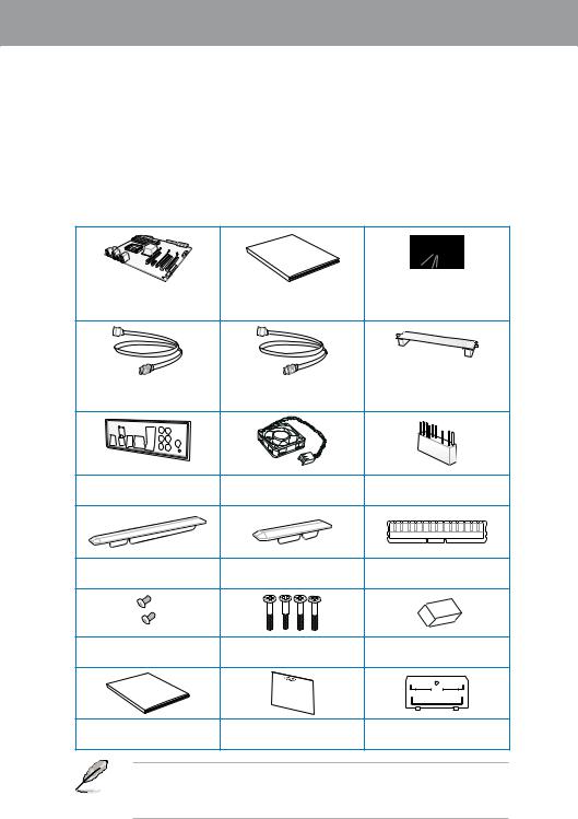
1.2Package contents
Check your motherboard package for the following items.
Manual
User
|
ASUS SABERTOOTH Z77 |
User guide |
Support DVD |
|
|
motherboard |
|||
|
2 x Serial ATA 6.0 Gb/s cables 2 x Serial ATA 3.0 Gb/s cables |
1 x ASUS SLI™ bridge |
|
|
connector |
||
|
1 x ASUS Q-Shield |
2 x Accessory Fans |
1 x 2-in-1 ASUS Q-Connector kit |
||
|
3 x PCIe x16 Slot dust covers |
3 x PCIe x1 Slot dust covers |
2 x DRAM slot dust covers |
||
|
M |
||||
|
3 |
||||
|
2 x short fan screws |
4 x long fan screws |
1 x Adhesive sponge for 35mm |
||
|
fan |
||||
|
warranty |
||||
|
-year |
||||
|
Five |
||||
|
1 x TUF Five-year warranty |
1 x TUF Certification card |
40mm I/O Cover fan lid |
||
|
manual (by region) |
||||
Chapter 1
• If any of the above items is damaged or missing, contact your retailer.
• The illustrated items above are for reference only.Actual product specifications may vary with different models.

1 Chapter
1.3Special features
1.3.1Product highlights
LGA1155 socket for Intel® 3rd/2nd Generation Core™ i7 / Core™ i5 / Core™ i3 / Pentium® / Celeron® Processors
This motherboard supports the Intel® 3rd/2nd generation Core™ i7/i5/i3/Pentium®/Celeron® processors in the LGA1155 package, with iGPU, memory, and PCI Express controllers integrated to support onboard graphics out with dedicated chipsets, 2-channel (4 DIMMs) DDR3 memory, and 16 PCI Express 3.0/2.0 lanes. This provides great graphics performance. Intel® 3rd/2nd generation Core™ i7/i5/i3/Pentium®/Celeron® processors are among the most powerful and energy efficient CPUs in the world.
Intel® Z77 Express Chipset
The Intel® Z77 Express Chipset is a single-chipset designed to support the 1155 socket Intel® 3rd/2nd generation Core™ i7/i5/ i3/Pentium®/Celeron® processors. It provides improved performance by utilizing serial point-to-point links, allowing increased bandwidth and stability.
Additionally, Z77 chipset provides 4 USB 3.0 ports for 10 times faster data retrieval speed. Moreover, Intel® Z77 Express Chipset can also enable iGPU function, letting users enjoy the latest Intel® integrated graphic performance.
PCI Express® 3.0
PCI Express® 3.0 (PCIe 3.0) is the latest PCI Express bus standard with improved encoding schemes that provide twice the performance of the current PCIe 2.0. The total bandwidth for a x16 link reaches a maximum of 32Gb/s, double the 16Gb/s of PCIe 2.0 (in x16 mode). As such, PCIe 3.0 provides users an unprecedented data speeds, combined with the convenience and seamless transition offered by complete backward compatibility with PCIe 1.0 and PCIe 2.0 devices. PCIe 3.0 will become a must-have feature for users who wish to
improve and optimize graphic performance, as well as have the latest technology available to them.
* PCI 3.0 speed is supported by Intel® 3rd generation Core™ processors.
Dual-Channel 1866 / 1600 / 1333 / 1066 MHz Support
The motherboard supports DDR3 memory that features data transfer rates of DDR3
1866 / 1600 / 1333 / 1066 MHz to meet the higher bandwidth requirements of the latest
3D graphics, multimedia, and Internet applications. The dual-channel DDR3 architecture enlarges the bandwidth of your system memory to boost system performance.
Quad-GPU SLI™ and Quad-GPU CrossFireX™ Support
Flexible Multi-GPU Solutions, Your Weapon of Choice!
SABERTOOTH Z77 brings you the multi-GPU choice of either SLI™ or CrossFireX. The motherboard features the most powerful Intel® Z77 platform to optimize PCIe allocation in multiple GPU configurations. Expect a brand-new gaming style you’ve never experienced before!
|
1-2 |
Chapter 1: Product Introduction |

Intel® Smart Response Technology
SSD Speed with HDD Capacity
Intel® Smart Response Technology boosts overall system performance. It uses an installed fast SSD (min 18.6GB available capacity required) as a cache for frequently accessed data.
Key benefits include reduced load and wait times, and lower power consumption through the elimination of unnecessary hard drive spin. This technology combines SSD performance with hard drive capacity, operating up to 4X faster than a hard drive-only system, and an important part of Green ASUS eco-friendly computing.
*Intel® Smart Response Technology is supported by 2nd/3rd generation Intel® Core™ processor family on Windows® 7™ operating systems.
**Operating systems must be installed on the HDD to launch Intel® Smart Response Technology. The capacity of the SSD is reserved for caching function.
Intel® Smart Connect Technology
Your computer could receive web updates with fresh content for selected applications even when setting the system to sleep. This means less time waiting for applications to start, update and sync with the Cloud, providing a more efficient way.
Intel® Rapid Start Technology
Allows your computer to quickly resume from a low-power hibernate state in seconds. Saving system memory to the designed SSD provides your computer a faster wake-up response time, while keeping the energy use low.
Complete USB 3.0 Integration
Double USB Access, Double Convenience
ASUS facilitates the strategic USB 3.0 accessibility for both the front and rear panel with 6 USB 3.0 ports in total. Experience the latest plug & play connectivity at speeds up to 10 times faster than USB 2.0. The SABERTOOTH Z77 affords greater convenience to high speed connectivity.
Extra SATA 6.0 Gb/s Support
Extra Ports, Extra Speed and Accessibility
The Intel® Z77 Express Chipset natively supports the next-generation Serial ATA (SATA) interface, delivering up to 6.0 Gb/s data transfer. ASUS provides extra SATA 6.0 Gb/s ports with enhanced scalability, faster data retrieval, and double the bandwidth of current bus systems.
1.3.2“Ultimate COOL!” Thermal Solutions
TUF Thermal Armor
New generation Thermal Armor boosts cooling with dual turbo fans, enhancing the original TUF thermal design, and helping direct hot air away from components and the motherboard via smart shunt funneling. It covers the entire board with more powerful airflow, and uses special heat pipes to expedite thermal removal, and make sure temperatures stay low. The dedicated I/O cover fan draws additional cold air in, and expels even more heat for improved stability, plus new Thermal Armor comes with special convection holes in the PCB to facilitate underside flow. It now sports a military-themed style, perfect for case modders.
Chapter 1

1 Chapter
TUF Thermal Radar
The TUF Thermal Radar monitors temperatures in critical parts of the motherboard in real time, automatically adjusting fan speeds to make sure the system maintains high stability. It consists of multiple sensors, giving users the ability to track each individually. Automatic calculation of ideal fan speeds based on different parameters selected manually for components has everything cooler and longer-lasting. New Fan Overtime keeps the two turbo fans running a few minutes post shutdown on standby power to remove the remaining heat. Stopping high temperatures from lingering in the case where they can cause damage, it extends system longevity, dropping the heat by as much as 7oC in just ten minutes. To
prolong fan lifespan, reduce noise, and lower power consumption, the new Fan Off has been added, automatically shutting off fans under either preset or manually-selected temperature thresholds.
1.3.3“TUF ENGINE!” Power Design
New DIGI+ Power Control
New DIGI+ Power Control includes multiple digital voltage controllers, allowing extra precise modulation and tuning of CPU, iGPU, and DRAM. This innovative and industry-leading ASUS technology provides an extremely accurate voltage tuning for better efficiency, stability, and performance. With the next generation Intel VRD 12.5 future power design, CPU wattage can be decreased by half, creating a cooler and quieter PC. This innovation of industry-leading ASUS technology provides the smartest control for better power saving scenarios.
TUF Components (Choke, Cap. & MOSFET; certified by militarystandard)
Get rugged performance even in the most challenging conditions with robust TUF chokes, solid capacitors, and MOSFETs – certified through third-party, military-grade testing. TUF
Chokes, also known as the “Alloy Choke”, is made of a compound of various types of metal instead standard iron, enables the support of up to a massive 40A of rated current, 25% higher than conventional component. Furthermore, the single piece packaging also eliminates the emission of vibration noise, delivering superb characteristics as well as durability under extreme conditions.
1.3.4“Safe & Stable!” Guardian Angel
Dust Defender
Dust particles and environmental contamination present a constant hazard to the optimal functioning of slots and connectors. Build up on contact points within slots compromises data transfer over time, negating the benefits of expensive and critical components such as graphics cards. Custom TUF design keeps this in mind with special shields that resist particulate entry, effectively extending slot and connector lifespan while promoting better performance.
MemOK!
MemOK! quickly ensures memory boot compatibility. This remarkable memory rescue tool requires a mere push of a button to patch memory issues. MemOK! determines fail-safe settings and dramatically improves your system boot success.
|
1-4 |
Chapter 1: Product Introduction |

ESD Guards
ESD (Electrostatic Discharge) Guards provides protection against electrostatic discharges, which can damage the motherboard’s components. The ASUS exclusive Anti-Static chip and circuit design, and the I/O shield provide four times better protection and ensure the motherboard’s lifespan.
1.3.5ASUS EZ DIY
ASUS UEFI BIOS (EZ Mode)
ASUS UEFI BIOS is a mouse-controlled user-friendly graphics interface that allows you to easily select performance settings, and drag and drop boot priorities with its EZ Mode
interface. ItsAdvanced Mode interface allows you to configure more advanced BIOS settings.
ASUS Q-Design
DIY Quickly, DIY Easily!
ASUS Q-Slot and Q-DIMM design speed up, simplify, and enhances your DIY (Do-It-Yourself) experience.
ASUS Q-Shield
Easy and Comfortable Installations
The specially designedASUS Q-Shield does without the usual «fingers» — making it convenient and easy to install. With better electric conductivity, it ideally protects your motherboard against static electricity and shields it against Electronic Magnetic Interference (EMI).
ASUS Q-Connector
Make Connection Quick and Accurate!
The ASUS Q-Connector allows you to connect or disconnect the chassis front panel cables in one easy step with one complete module. This unique adapter eliminates the trouble of plugging in one cable at a time, making the connection quick and accurate.
ASUS EZ-Flash 2
ASUS EZ Flash 2 is a user-friendly utility that allows you to update the BIOS without using a bootable floppy disk or an OS-based utility.
1.3.6ASUS Exclusive Features
USB 3.0 Boost
ASUS USB 3.0 Boost technology supports UASP (USB Attached SCSI Protocol) and automatically increases a USB 3.0 device’s transfer speed up to 170%.
Chapter 1

1 Chapter
USB Charger+
With a dedicated onboard controller, quick-charge your USB devices such iProducts, smartphones, tablets, and other portable devices 50% faster, even when the PC is powered off, in sleep, or hibernation.
* USB Charger+ only applies to the bottom port of USB3_12.
USB BIOS Flashback
With USB BIOS Flashback, simply connect a USB flash drive containing the UEFI BIOS file to the USB 3.0 port, press the BIOS Flashback button for three seconds, and the BIOS is updated automatically. With its Windows-compatible application, you can regularly check for UEFI BIOS updates and download the latest UEFI BIOS automatically.
* USB BIOS Flashback only applies to the bottom port of USB3_12.
Network iControl
ASUS Network iControl is an intuitive one-stop network control center that makes it easier for you to manage your network bandwidth and allows you to set, monitor, and schedule the bandwidth priorities for your network programs. It also allows you to automatically connect to a PPPoE network for a more convenient online experience.
1.3.7Other special features
LucidLogix Virtu MVP
LucidLogix Virtu MVP featuring HyperFormance™ Technology boosts your PCIe graphics card up to 30% beyond its original performance. Designed for Intel® processor graphics and Windows® 7 PCs, it perfectly combines the performance of discrete graphic cards with fast computing iGPU. Also, with newly designed Virtual Sync, users can enjoy a smoother gaming experience by eliminating tearing artifacts. LucidLogix Virtu MVP can also dynamically assigns tasks to the best available graphics resource, based on power, performance, and system load. This allows users to fully utilize 3x faster video conversion with Intel® Quick Sync Video technology while retaining high-end 3D rendering and gaming performance, provided by both NVIDIA and AMD graphic cards. When the PCIe graphic cards are not required, the graphics control switches to the Intel® processor graphics, reducing the PCIe graphics power use down to zero, making the system more environment-friendly. For users searching for perfection, LucidLogix Virtu MVP provides great graphical performance, and best quality and efficiency.
*LucidLogix Virtu MVP supports Windows® operating system.
**Intel® Quick Sync Video feature is supported by 3rd/2nd generation Intel® Core™ processor family
|
1-6 |
Chapter 1: Product Introduction |

DisplayPort 1.1a Support
DisplayPort is a digital display interface standard that delivers up to 10.8 Gbps of bandwidth over standard cables, providing billions of colors and bidirectional communications, thus enabling the fastest refresh rates, and the highest resolution digital display through a single cable. Also, it supports HDCP copy protection for Blu-ray discs. Simply output 3D signals through the connected DisplayPort 1.1a cable with your 3D display, then you can sit back and enjoy a perfect 3D animation experience.
HDMI 1.4a Support
High Definition Multimedia Surface (HDMI) is a set of digital video standards that delivers multi-channel audio and uncompressed digital video for full HD 1080p visuals through a single cable. Supporting HDCP copy protection such as HD DVD and blu-ray discs, HDMI provides you with the highest quality home theater experience.
ErP Ready
The motherboard is European Union’s Energy-related Products (ErP) ready, and ErP requires products to meet certain energy efficiency requirement in regards to energy consumption. This is in line withASUS vision of creating environment-friendly and energy-efficient products through product design and innovation to reduce carbon footprint of the product and thus mitigate environmental impacts.
Chapter 1

1 Chapter
|
1-8 |
Chapter 1: Product Introduction |
![]()
Chapter 2
|
Chapter 2: |
Hardware information |
2.1Before you proceed
Take note of the following precautions before you install motherboard components or change any motherboard settings.
• Unplug the power cord from the wall socket before touching any component.
• Before handling components, use a grounded wrist strap or touch a safely grounded object or a metal object, such as the power supply case, to avoid damaging them due to static electricity.
•Hold components by the edges to avoid touching the ICs on them.
•Whenever you uninstall any component, place it on a grounded antistatic pad or in the bag that came with the component.
•Before you install or remove any component, ensure that the ATX power supply is switched off or the power cord is detached from the power supply. Failure to do so may cause severe damage to the motherboard, peripherals, or components.

2.2Motherboard overview
2.2.1Motherboard layout
2 Chapter
Refer to 2.2.8 Internal connectors and 2.3.11 Rear panel connection for more information about rear panel connectors and internal connectors.
|
2-2 |
Chapter 2: Hardware information |

Layout contents
|
Connectors/Jumpers/Slots |
Page |
||
|
1. |
ATX power connectors (24-pin EATXPWR, 8-pin EATX12V) |
2-24 |
|
|
2. |
CPU, chassis, and assistant fan connectors |
2-22 |
|
|
(4-pin CPU_FAN, CHA_FAN1–4, CPU_OPT, 3-pin ASST_FAN) |
|||
|
3. |
LGA1155 CPU socket |
2-4 |
|
|
4. |
DDR3 DIMM slots |
2-5 |
|
|
5. |
MemOK! switch |
2-15 |
|
|
6. |
USB 3.0 connector (20-1 pin USB3_34) |
2-20 |
|
|
7. |
Intel® Z77 Serial ATA 6Gb/s connectors |
2-17 |
|
|
(7-pin SATA6G_1/2 [brown]) |
|||
|
8. |
Intel® Z77 Serial ATA 3Gb/s connectors |
2-18 |
|
|
(7-pin SATA3G_3–6 [black]) |
|||
|
9. |
ASMedia® Serial ATA 6Gb/s connectors |
2-19 |
|
|
(7-pin SATA6G_E1/E2 [gray]) |
|||
|
10. |
System panel connector (20-8 pin PANEL) |
2-25 |
|
|
11. |
USB 2.0 connectors (10-1 pin USB56, USB78, USB910) |
2-21 |
|
|
12. |
Standby power LED (SB_PWR) |
2-16 |
|
|
13. |
Clear RTC RAM (3-pin CLRTC) |
2-14 |
|
|
14. |
Front panel audio connector (10-1 pin AAFP) |
2-23 |
|
|
15. |
Digital audio connector (4-1 pin SPDIF_OUT) |
2-21 |
Chapter 2
2 Chapter
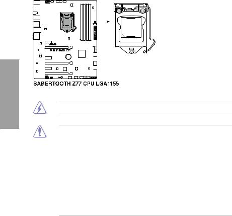
2.2.2Central Processing Unit (CPU)
The motherboard comes with a surface mount LGA1155 socket designed for the Intel® 3rd/2nd Generation Core™ i7 / Core™ i5 / Core™ i3 / Pentium / Celeron Processors.
Ensure that all power cables are unplugged before installing the CPU.
•The LGA1156 CPU is incompatible with the LGA1155 socket. DO NOT install a LGA1156 CPU on the LGA1155 socket.
•Upon purchase of the motherboard, ensure that the PnP cap is on the socket and the socket contacts are not bent. Contact your retailer immediately if the PnP cap is missing, or if you see any damage to the PnP cap/socket contacts/motherboard components. ASUS will shoulder the cost of repair only if the damage is shipment/ transit-related.
•Keep the cap after installing the motherboard. ASUS will process Return Merchandise
Authorization (RMA) requests only if the motherboard comes with the cap on the
LGA1155 socket.
•The product warranty does not cover damage to the socket contacts resulting from incorrect CPU installation/removal, or misplacement/loss/incorrect removal of the PnP cap.
|
2-4 |
Chapter 2: Hardware information |
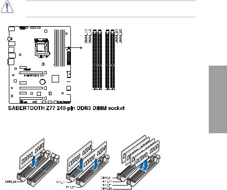
2.2.3System memory
The motherboard comes with four Double Data Rate 3 (DDR3) Dual Inline Memory Modules (DIMM) slots.
A DDR3 module is notched differently from a DDR or DDR2 module. DO NOT install a DDR or DDR2 memory module to the DDR3 slot.
Chapter 2
Recommended memory configurations

Memory configurations
You may install 1GB, 2GB, 4GB and 8GB unbuffered and non ECC DDR3 DIMMs into the DIMM sockets.
2 Chapter
•You may install varying memory sizes in ChannelA, and Channel B. The system maps the total size of the lower-sized channel for the dual-channel configuration.Any excess memory from the higher-sized channel is then mapped for single-channel operation.
•According to Intel CPU spec, DIMM voltage below 1.65V is recommended to protect the CPU.
•Always install DIMMs with the same CAS latency. For optimum compatibility, we recommend that you obtain memory modules from the same vendor.
•Due to the memory address limitation on 32-bit Windows OS, when you install 4GB or more memory on the motherboard, the actual usable memory for the OS can be about 3GB or less. For effective use of memory, we recommend that you do any of the following:
—Use a maximum of 3GB system memory if you are using a 32-bit Windows OS.
—Install a 64-bit Windows OS when you want to install 4GB or more on the motherboard.
For more details, refer to the Microsoft® support site at http://support.microsoft.com/kb/929605/en-us.
•This motherboard does not support DIMMs made up of 512Mb (64MB) chips or less (Memory chip capacity counts in Megabit, 8 Megabit/Mb = 1 Megabyte/MB).
•The default memory operation frequency is dependent on its Serial Presence Detect (SPD), which is the standard way of accessing information from a memory module. Under the default state, some memory modules for overclocking may operate at a lower frequency than the vendor-marked value. To operate at the vendor-marked
or at a higher frequency, refer to section 3.4 Ai Tweaker menu for manual memory frequency adjustment.
•For system stability, use a more efficient memory cooling system to support a full memory load (4 DIMMs) or overclocking condition.
|
2-6 |
Chapter 2: Hardware information |

SABERTOOTH Z77 Motherboard Qualified Vendors Lists (QVL)
DDR3 1333 MHz capability
|
SS/ |
DIMM socket support |
|||||||||
|
Vendors |
Part No. |
Size |
Chip Brand |
Chip NO. |
Timing |
Voltage |
(Optional) |
4 |
||
|
DS |
1 |
2 |
||||||||
|
DIMM |
DIMM |
DIMM |
||||||||
|
A-DATA |
AD63I1B0823EV |
2GB |
SS |
A-DATA |
3CCA-1509A |
— |
— |
• |
• |
• |
|
A-DATA |
AXDU1333GC2G9(XMP) |
2GB |
SS |
— |
— |
9-9-9-24 |
• |
• |
• |
|
|
A-DATA |
AD63I1C1624EV |
4GB |
DS |
A-DATA |
3CCA-1509A |
— |
— |
• |
• |
• |
|
A-DATA |
SU3U1333W8G9(XMP) |
8GB |
DS |
ELPIDA |
J4208BASE-DJ-F |
— |
— |
• |
• |
• |
|
Apacer |
78.A1GC6.9L1 |
2GB |
DS |
Apacer |
AM5D5808FEQSBG |
9 |
— |
• |
• |
• |
|
Apacer |
78.B1GDE.9L10C |
4GB |
DS |
Apacer |
AM5D5908CEHSBG |
9 |
— |
• |
• |
• |
|
CORSAIR |
TW3X4G1333C9A |
4GB |
DS |
— |
— |
9-9-9-24 |
1.5 |
• |
• |
|
|
(2x2GB) |
||||||||||
|
CORSAIR |
CMX8GX3M2A1333C9 |
8GB |
DS |
— |
— |
9-9-9-24 |
1.5 |
• |
• |
• |
|
(XMP) |
( 2x4GB) |
|||||||||
|
ELPIDA |
EBJ20UF8BCF0-DJ-F |
2GB |
SS |
Elpida |
J2108BCSE-DJ-F |
— |
— |
• |
• |
• |
|
ELPIDA |
EBJ41UF8BCF0-DJ-F |
4GB |
DS |
ELPIDA |
J2108BCSE-DJ-F |
— |
— |
• |
• |
• |
|
G.SKILL |
F3-10600CL9D-4GBNT |
4GB |
DS |
G.SKILL |
D3 128M8CE9 2GB |
9-9-9-24 |
1.5 |
• |
• |
• |
|
(2x2GB) |
||||||||||
|
G.SKILL |
F3-10666CL9D-8GBRL |
8GB |
DS |
— |
— |
9-9-9-24 |
1.5 |
• |
• |
• |
|
(2x4GB) |
||||||||||
|
G.SKILL |
F3-10666CL9D-8GBXL |
8GB ( |
DS |
— |
— |
9-9-9-24 |
1.5 |
• |
• |
• |
|
2x4GB) |
||||||||||
|
GEIL |
GET316GB1333C9QC |
16GB |
DS |
— |
— |
9-9-9-24 |
1.5 |
• |
• |
• |
|
(4x4GB) |
||||||||||
|
GEIL |
GG34GB1333C9DC |
4GB |
DS |
GEIL |
GL1L128M88BA |
9-9-9-24 |
1.3 |
• |
• |
• |
|
(2x2GB) |
115FW |
|||||||||
|
GEIL |
GG34GB1333C9DC |
4GB |
DS |
GEIL |
GL1L128M88BA |
9-9-9-24 |
1.3 |
• |
• |
• |
|
(2x2GB) |
15B |
|||||||||
|
GEIL |
GB34GB1333C7DC |
4GB |
DS |
GEIL |
GL1L128M88BA15FW |
7-7-7-24 |
1.5 |
• |
• |
• |
|
(2x2GB) |
||||||||||
|
GEIL |
GVP38GB1333C9DC |
8GB |
DS |
— |
— |
9-9-9-24 |
1.5 |
• |
• |
• |
|
(2x4GB) |
||||||||||
|
Hynix |
HMT325U6BFR8C-H9 |
2GB |
SS |
Hynix |
H5TQ2G83BFR |
— |
— |
• |
• |
• |
|
Hynix |
HMT125U6TFR8A-H9 |
2GB |
DS |
Hynix |
H5TC1G83TFR |
— |
— |
• |
• |
• |
|
KINGMAX |
FLFE85F-C8KL9 |
2GB |
SS |
KINGMAX |
KFC8FNLXF-DXX-15A |
— |
— |
• |
• |
• |
|
KINGMAX |
FLFE85F-C8KM9 |
2GB |
SS |
Kingmax |
KFC8FNMXF-BXX-15A |
— |
— |
• |
• |
• |
|
KINGMAX |
FLFE85F-B8KL9 |
2GB |
DS |
KINGMAX |
KFB8FNLXL-BNF-15A |
— |
— |
• |
• |
• |
|
KINGMAX |
FLFF65F-C8KL9 |
4GB |
DS |
KINGMAX |
KFC8FNLXF-DXX-15A |
— |
— |
• |
• |
• |
|
KINGMAX |
FLFF65F-C8KM9 |
4GB |
DS |
Kingmax |
KFC8FNMXF-BXX-15A |
— |
— |
• |
• |
• |
|
KINGSTON |
KVR1333D3S8N9/2G |
2GB |
SS |
Micron |
IFD77 D9LGK |
— |
1.5 |
• |
• |
• |
|
KINGSTON |
KVR1333D3N9/2G |
2GB |
DS |
Kingston |
D1288JPNDPLD9U |
9 |
1.5 |
• |
• |
• |
|
KINGSTON |
KHX1333C9D3UK2/4GX |
4GB |
DS |
— |
— |
9 |
1.25 |
• |
• |
• |
|
(XMP) |
(2x2GB) |
|||||||||
|
KINGSTON |
KVR1333D3N9K2/4G |
4GB |
DS |
KINGSTON |
D1288JEMFPGD9U |
— |
1.5 |
• |
• |
• |
|
(2x2GB) |
||||||||||
|
KINGSTON |
KVR1333D3E9S/4G |
4GB |
DS |
Elpida |
J2108ECSE-DJ-F |
9 |
1.5 |
• |
• |
• |
|
MICRON |
MT4JTF12864AZ-1G4D1 |
1GB |
SS |
Micron |
D9LGQ |
— |
— |
• |
||
|
MICRON |
MT8JTF25664AZ-1G4D1 |
2GB |
SS |
Micron |
D9LGK |
— |
— |
• |
• |
• |
|
MICRON |
MT8JTF25664AZ-1G4D1 |
2GB |
SS |
Micron |
D9LGK |
— |
— |
• |
• |
• |
|
MICRON |
MT8JTF25664AZ-1G4M1 |
2GB |
SS |
MICRON |
D9PFJ |
— |
— |
• |
• |
• |
|
MICRON |
MT16JTF51264AZ-1G4D1 |
4GB |
DS |
Micron |
D9LGK |
— |
— |
• |
• |
• |
|
OCZ |
OCZ3G1333LV4GK |
4GB |
DS |
— |
— |
9-9-9 |
1.65 |
• |
• |
|
|
(2x2GB) |
||||||||||
|
OCZ |
OCZ3G1333LV8GK |
8GB |
DS |
— |
— |
9-9-9 |
1.65 |
• |
• |
• |
|
(2x4GB) |
||||||||||
|
OCZ |
OCZ3G1333LV8GK |
8GB |
DS |
— |
— |
9-9-9 |
1.65 |
• |
• |
|
|
(2x4GB) |
||||||||||
|
OCZ |
OCZ3RPR1333C9LV8GK |
8GB |
DS |
— |
— |
9-9-9 |
1.65 |
• |
• |
• |
|
(2x4GB) |
||||||||||
|
PSC |
PC310600U-9-10-A0 |
1GB |
SS |
PSC |
A3P1GF3FGF |
— |
— |
• |
• |
• |
|
PSC |
PC310600U-9-10-B0 |
2GB |
DS |
PSC |
A3P1GF3FGF |
— |
— |
• |
• |
• |
|
SAMSUNG |
M378B5773DH0-CH9 |
2GB |
SS |
SAMSUNG |
K4B2G08460 |
— |
— |
• |
• |
• |
Chapter 2

2 Chapter
SABERTOOTH Z77 Motherboard Qualified Vendors Lists (QVL)
DDR3 1333 MHz capability (continued)
|
SS/ |
DIMM socket support |
||||||||||
|
Vendors |
Part No. |
Size |
Chip Brand |
Chip NO. |
Timing |
Voltage |
(Optional) |
4 |
|||
|
DS |
1 |
2 |
|||||||||
|
DIMM |
DIMM |
DIMM |
|||||||||
|
SAMSUNG |
M378B5673FH0-CH9 |
2GB |
DS |
SAMSUNG |
K4B1G0846F |
— |
— |
• |
• |
• |
|
|
SAMSUNG |
M378B5273CH0-CH9 |
4GB |
DS |
SAMSUNG |
K4B2G0846C |
K4B2G0846C |
— |
• |
• |
• |
|
|
SAMSUNG |
M378B5273DH0-CH9 |
4GB |
DS |
SAMSUNG |
K4B2G08460 |
— |
— |
• |
• |
• |
|
|
SAMSUNG |
M378B1G73AH0-CH9 |
8GB |
DS |
SAMSUNG |
K4B4G0846A-HCH9 |
— |
— |
• |
• |
• |
|
|
Transcend |
JM1333KLN-2G (582670) |
2GB |
SS |
Micron |
ICD77 C9LGK |
— |
— |
• |
• |
||
|
Transcend |
JM1333KLN-2G |
2GB |
SS |
Transcend |
TK483PCW3 |
— |
— |
• |
• |
• |
|
|
Transcend |
TS256MLK64V3N |
2GB |
SS |
Micron |
ICD77 D9LGK |
9 |
— |
• |
• |
• |
|
|
( 585541 ) |
|||||||||||
|
Transcend |
TS256MLK64V3N |
2GB |
SS |
Hynix |
H5TQ2G83BFR |
9 |
— |
• |
• |
• |
|
|
(566577) |
|||||||||||
|
Transcend |
TS256MLK64V3N |
2GB |
SS |
Micron |
D9LGK |
9 |
— |
• |
• |
• |
|
|
(574206) |
|||||||||||
|
Transcend |
JM1333KLN-4G |
4GB |
DS |
Transcend |
TK483PCW3 |
9 |
— |
• |
• |
• |
|
|
( 583782 ) |
|||||||||||
|
Transcend |
JM1333KLN-4G |
4GB |
DS |
Transcend |
TK483PCW3 |
— |
— |
• |
• |
• |
|
|
Transcend |
TS512MLK64V3N |
4GB |
DS |
Micron |
IED27 D9LGK |
9 |
— |
• |
• |
• |
|
|
( 585538 ) |
• |
||||||||||
|
Transcend |
TS512MLK64V3N |
4GB |
DS |
Micron |
D9LGK |
9 |
— |
• |
• |
||
|
(574831) |
|||||||||||
|
ACTICA |
ACT1GHU64B8F1333S |
1GB |
SS |
SAMSUNG |
K4B1G0846F |
— |
— |
• |
• |
• |
|
|
ACTICA |
ACT1GHU72C8G1333S |
1GB |
SS |
SAMSUNG |
K4B1G0846F(ECC) |
— |
— |
• |
• |
||
|
ACTICA |
ACT2GHU64B8G1333M |
2GB |
DS |
Micron |
D9KPT |
— |
— |
• |
• |
• |
|
|
ACTICA |
ACT2GHU64B8G1333S |
2GB |
DS |
SAMSUNG |
K4B1G0846F |
— |
— |
• |
• |
• |
|
|
ACTICA |
ACT2GHU72D8G1333M |
2GB |
DS |
Micron |
D9KPT(ECC) |
— |
— |
• |
• |
• |
|
|
ACTICA |
ACT2GHU72D8G1333S |
2GB |
DS |
SAMSUNG |
K4B1G0846F(ECC) |
— |
— |
• |
• |
• |
|
|
ACTICA |
ACT4GHU64B8H1333H |
4GB |
DS |
Hynix |
H5TQ2G83AFR |
— |
— |
• |
• |
• |
|
|
ACTICA |
ACT4GHU72D8H1333H |
4GB |
DS |
Hynix |
H5TQ2G83AFR(ECC) |
— |
— |
• |
• |
• |
|
|
ATP |
AQ56M72E8BJH9S |
2GB |
DS |
SAMSUNG |
K4B1G0846F(ECC) |
— |
— |
• |
• |
• |
|
|
ATP |
AQ12M72E8BKH9S |
4GB |
DS |
SAMSUNG |
K4B2G0846C(ECC) |
— |
— |
• |
• |
• |
|
|
BUFFALO |
D3U1333-1G |
1GB |
SS |
Elpida |
J1108BFBG-DJ-F |
— |
— |
• |
• |
• |
|
|
BUFFALO |
D3U1333-2G |
2GB |
DS |
Elpida |
J1108BFBG-DJ-F |
— |
• |
• |
• |
||
|
BUFFALO |
D3U1333-4G |
4GB |
DS |
NANYA |
NT5CB256M8BN-CG |
— |
• |
• |
• |
||
|
EK Memory |
EKM324L28BP8-I13 |
4GB |
DS |
— |
— |
9 |
— |
• |
• |
• |
|
|
(2x2GB) |
|||||||||||
|
Elixir |
M2F2G64CB88B7N-CG |
2GB |
SS |
Elixir |
N2CB2G808N-CG |
— |
— |
• |
• |
• |
|
|
Elixir |
M2F2G64CB88D7N-CG |
2GB |
SS |
Elixir |
M2CB2G8BDN-CG |
— |
— |
• |
• |
• |
|
|
Elixir |
M2F4G64CB8HD5N-CG |
4GB |
DS |
Elixir |
M2CB2G8BDN-CG |
— |
— |
• |
• |
• |
|
|
GoodRam |
GR1333D364L9/2G |
2GB |
DS |
Qimonda |
IDSH1G-03A1F1C-13H |
— |
— |
• |
• |
• |
|
|
KINGTIGER |
F10DA2T1680 |
2GB |
DS |
KINGTIGER |
KTG1333PS1208NST-C9 |
— |
— |
• |
• |
• |
|
|
KINGTIGER |
KTG2G1333PG3 |
2GB |
DS |
— |
— |
— |
— |
• |
• |
• |
|
|
Patriot |
PSD32G13332 |
2GB |
DS |
Prtriot |
PM128M8D3BU-15 |
9 |
— |
• |
• |
• |
|
|
Patriot |
PGS34G1333LLKA |
4GB |
DS |
— |
— |
7-7-7-20 |
1.7 |
• |
• |
• |
|
|
(2x2GB) |
|||||||||||
|
Patriot |
PG38G1333EL(XMP) |
8GB |
DS |
— |
— |
— |
1.5 |
• |
• |
• |
|
|
RiDATA |
C304627CB1AG22Fe |
2GB |
DS |
RiDATA |
C304627CB1AG22Fe |
9 |
— |
• |
• |
• |
|
|
RiDATA |
E304459CB1AG32Cf |
4GB |
DS |
RiDATA |
E304459CB1AG32Cf |
9 |
— |
• |
• |
• |
|
|
SanMax |
SMD4G68H1P-13HZ |
4GB |
DS |
Hynix |
H5TQ2G83BFRH9C |
— |
1.5 |
• |
• |
• |
|
|
Silicon |
SP001GBLTE133S01 |
1GB |
SS |
NANYA |
NT5CB128M8AN-CG |
— |
— |
• |
• |
• |
|
|
Power |
|||||||||||
|
Silicon |
SP001GBLTU133S02 |
1GB |
SS |
S-POWER |
10YT3E5 |
9 |
— |
• |
• |
• |
|
|
Power |
|||||||||||
|
Silicon |
SP002GBLTE133S01 |
2GB |
DS |
NANYA |
NT5CB128M8AN-CG |
— |
— |
• |
• |
• |
|
|
Power |
|||||||||||
|
Team |
TXD31024M1333C7 |
1GB |
SS |
Team |
T3D1288LT-13 |
7-7-7-21 |
1.75 |
• |
• |
• |
|
|
(XMP) |
|||||||||||
|
Team |
TXD31048M1333C7-D |
1GB |
SS |
Team |
T3D1288LT-13 |
7-7-7-21 |
1.75 |
• |
• |
||
|
(XMP) |
|||||||||||
|
Team |
TXD32048M1333C7-D |
2GB |
DS |
Team |
T3D1288LT-13 |
7-7-7-21 |
1.5-1.6 |
• |
• |
• |
|
|
(XMP) |
|
2-8 |
Chapter 2: Hardware information |

SABERTOOTH Z77 Motherboard Qualified Vendors Lists (QVL)
DDR3 1600 MHz capability
|
DIMM socket support |
|||||||||||
|
Vendors |
Part No. |
Size |
SS/ |
Chip |
Chip NO. |
Timing |
Voltage |
(Optional) |
|||
|
DS |
Brand |
||||||||||
|
1 DIMM |
2 |
4 |
|||||||||
|
DIMM |
DIMM |
||||||||||
|
A-DATA |
AM2U16BC2P1 |
2GB |
SS |
A-DATA |
3CCD-1509A |
— |
— |
• |
• |
• |
|
|
A-DATA |
AM2U16BC4P2 |
4GB |
DS |
A-DATA |
3CCD-1509A |
— |
— |
• |
• |
• |
|
|
A-DATA |
AX3U1600GC4G9(XMP) |
4GB |
DS |
— |
— |
— |
1.55~ |
• |
• |
• |
|
|
1.75 |
|||||||||||
|
A-DATA |
AX3U1600PC4G8(XMP) |
4GB |
DS |
— |
— |
8-8-8-24 |
1.55~ |
• |
• |
• |
|
|
1.75 |
|||||||||||
|
CORSAIR |
HX3X12G1600C9(XMP) |
12GB (6x2GB) |
DS |
— |
— |
9-9-9-24 |
1.6 |
• |
• |
• |
|
|
CORSAIR |
CMZ16GX3M4A1600C9(XMP) |
16GB (4x4GB) |
DS |
— |
— |
9-9-9-24 |
1.5 |
• |
• |
• |
|
|
CORSAIR |
CMG4GX3M2A1600C6 |
4GB (2x2GB) |
DS |
— |
— |
6-6-6-18 |
1.65 |
• |
• |
• |
|
|
CORSAIR |
CMP6GX3M3A1600C8(XMP) |
6GB (3x2GB) |
DS |
— |
— |
8-8-8-24 |
1.65 |
• |
• |
• |
|
|
CORSAIR |
CMP6GX3M3A1600C8(XMP) |
6GB (3x2GB) |
DS |
— |
— |
8-8-8-24 |
1.65 |
• |
• |
• |
|
|
CORSAIR |
CMX6GX3M3C1600C7(XMP) |
6GB (3x2GB) |
DS |
— |
— |
7-8-7-20 |
1.65 |
• |
• |
• |
|
|
CORSAIR |
CMZ8GX3M2A1600C8(XMP) |
8GB (2x4GB) |
DS |
— |
— |
8-8-8-24 |
1.5 |
• |
• |
• |
|
|
CORSAIR |
CMZ8GX3M2A1600C9(XMP) |
8GB (2x4GB) |
DS |
— |
— |
9-9-9-24 |
1.5 |
• |
• |
• |
|
|
Crucial |
BL12864BN1608.8FF(XMP) |
2GB (2x1GB) |
SS |
— |
— |
8-8-8-24 |
1.65 |
• |
• |
• |
|
|
G.SKILL |
F3-12800CL7Q-16GBXH(XMP) |
16GB (4x4GB) |
DS |
— |
— |
7-8-7-24 |
1.6 |
• |
• |
• |
|
|
G.SKILL |
F3-12800CL9Q-16GBXL(XMP) |
16GB (4x4GB) |
DS |
— |
— |
9-9-9-24 |
1.5 |
• |
• |
• |
|
|
G.SKILL |
F3-12800CL7D-8GBRH(XMP) |
8GB (2x4GB) |
DS |
— |
— |
7-8-7-24 |
1.6 |
• |
• |
||
|
G.SKILL |
F3-12800CL9D-8GBRL(XMP) |
8GB (2x4GB) |
DS |
— |
— |
9-9-9-24 |
1.5 |
• |
• |
• |
|
|
G.SKILL |
F3-12800CL9D-8GBSR2(XMP) |
8GB (2x4GB) |
DS |
— |
— |
9-9-9-24 |
1.25 |
• |
• |
• |
|
|
G.SKILL |
F3-12800CL8D-8GBECO(XMP) |
8GB (2x4GB) |
DS |
— |
— |
8-8-8-24 |
1.35 |
• |
• |
• |
|
|
GEIL |
GET316GB1600C9QC(XMP) |
16GB (4x4GB) |
DS |
— |
— |
9-9-9-28 |
1.6 |
• |
• |
• |
|
|
KINGSTON |
KHX1600C9D3K3/12GX(XMP) |
12GB (3x4GB) |
DS |
— |
— |
9 |
1.65 |
• |
• |
||
|
KINGSTON |
KHX1600C9D3T1BK3/12GX |
12GB (3x4GB) |
DS |
— |
— |
9 |
1.65 |
• |
• |
• |
|
|
(XMP) |
|||||||||||
|
KINGSTON |
KHX1600C9D3K3/12GX(XMP) |
12GB(3x4GB) |
DS |
— |
— |
— |
1.65 |
• |
• |
• |
|
|
KINGSTON |
KHX1600C9D3K6/24GX(XMP) |
24GB (6x4GB) |
DS |
— |
— |
9 |
1.65 |
• |
• |
• |
|
|
KINGSTON |
KHX1600C8D3K2/4GX(XMP) |
4GB (2x2GB) |
DS |
— |
— |
8 |
1.65 |
• |
• |
||
|
KINGSTON |
KHX1600C9D3K2/4GX(XMP) |
4GB (2x2GB) |
DS |
— |
— |
— |
1.65 |
• |
• |
• |
|
|
KINGSTON |
KHX1600C9D3LK2/4GX(XMP) |
4GB (2x2GB) |
DS |
— |
— |
— |
1.65 |
• |
• |
• |
|
|
KINGSTON |
KHX1600C9D3X2K2/4GX(XMP) |
4GB (2x2GB) |
DS |
— |
— |
9 |
1.65 |
• |
• |
• |
|
|
KINGSTON |
KHX1600C9D3K3/6GX(XMP) |
6GB (3x2GB) |
DS |
— |
— |
9 |
1.65 |
• |
• |
• |
|
|
KINGSTON |
KHX1600C9D3K3/6GX(XMP) |
6GB (3x2GB) |
DS |
— |
— |
9 |
1.65 |
• |
• |
• |
|
|
KINGSTON |
KHX1600C9D3T1K3/6GX |
6GB (3x2GB) |
DS |
— |
— |
— |
1.65 |
• |
• |
||
|
(XMP) |
|||||||||||
|
KINGSTON |
KHX1600C9D3T1K3/6GX |
6GB (3x2GB) |
DS |
— |
— |
9 |
1.65 |
• |
• |
• |
|
|
(XMP) |
|||||||||||
|
OCZ |
OCZ3BE1600C8LV4GK |
4GB(2x2GB) |
DS |
— |
— |
8-8-8 |
1.65 |
• |
• |
||
|
Transcend |
JM1600KLN-8GK |
8GB (2x4GB) |
DS |
Transcend |
TK483PCW3 |
— |
— |
• |
• |
• |
|
|
Asint |
SLZ3128M8-EGJ1D(XMP) |
2GB |
DS |
Asint |
3128M8-GJ1D |
— |
— |
• |
• |
• |
|
|
EK Memory |
EKM324L28BP8-I16(XMP) |
4GB (2x2GB) |
DS |
— |
— |
9 |
— |
• |
• |
• |
|
|
EK Memory |
EKM324L28BP8-I16(XMP) |
4GB (2 x 2GB) |
DS |
— |
— |
9 |
— |
• |
• |
• |
|
|
GoodRam |
GR1600D364L9/2G |
2GB |
DS |
GoodRam |
GF1008KC-JN |
— |
— |
• |
• |
• |
|
|
KINGTIGER |
KTG2G1600PG3(XMP) |
2GB |
DS |
— |
— |
— |
— |
• |
• |
• |
|
|
Mushkin |
996805(XMP) |
4GB (2x2GB) |
DS |
— |
— |
6-8-6-24 |
1.65 |
• |
• |
• |
|
|
Patriot |
PX7312G1600LLK(XMP) |
12GB (3x4GB) |
DS |
— |
— |
8-9-8-24 |
1.65 |
• |
• |
||
|
Patriot |
PGS34G1600LLKA2 |
4GB (2x2GB) |
DS |
— |
— |
8-8-8-24 |
1.7 |
• |
• |
• |
|
|
Patriot |
PGS34G1600LLKA |
4GB (2x2GB) |
DS |
— |
— |
7-7-7-20 |
1.7 |
• |
|||
|
Patriot |
PVV38G1600LLK(XMP) |
8GB (2x4GB) |
DS |
— |
— |
8-9-8-24 |
1.65 |
• |
• |
• |
|
|
Patriot |
PX538G1600LLK(XMP) |
8GB (2x4GB) |
DS |
— |
— |
8-9-8-24 |
1.65 |
• |
• |
• |
|
|
SanMax |
SMD-4G68HP-16KZ |
4GB |
DS |
Hynix |
H5TQ2G |
— |
1.5 |
• |
• |
• |
|
|
83BFRPBC |
|||||||||||
|
Team |
TXD31024M1600C8-D(XMP) |
1GB |
SS |
Team |
T3D1288RT-16 |
8-8-8-24 |
1.65 |
• |
• |
• |
|
|
Team |
TXD32048M1600HC8-D(XMP) |
2GB |
DS |
Team |
T3D1288RT-16 |
8-8-8-24 |
1.65 |
• |
• |
• |
Chapter 2

2 Chapter
SABERTOOTH Z77 Motherboard Qualified Vendors Lists (QVL)
DDR3 1800 MHz capability
|
Vendors |
Part No. |
Size |
SS/ |
Chip |
Chip |
Timing |
Voltage |
DIMM socket support (Optional) |
||
|
DS |
Brand |
NO. |
1 DIMM |
2 DIMM |
4 DIMM |
|||||
|
G.SKILL |
F3-14400CL9D-4GBRL(XMP) |
4GB (2x2GB) |
DS |
— |
9-9-9-24 |
1.60 |
• |
• |
• |
SABERTOOTH Z77 Motherboard Qualified Vendors Lists (QVL)
DDR3 1866 MHz capability
|
Vendors |
Part No. |
Size |
SS/ |
Chip |
Chip |
Timing |
Voltage |
DIMM socket support (Optional) |
|||
|
DS |
Brand |
NO. |
1 DIMM |
2 DIMM |
4 DIMM |
||||||
|
A-DATA |
AX3U1866GC2G9B(XMP) |
2GB |
SS |
— |
— |
9-11-9-27 |
1.55-1.75 |
• |
• |
• |
|
|
A-DATA |
AX3U1866GC4G9B(XMP) |
4GB |
DS |
9-11-9-27 |
1.55-1.75 |
• |
• |
• |
|||
|
CORSAIR |
CMT3GX3M4X1866C9(XMP) |
32GB (4x8GB) |
DS |
9-10-9-27 |
1.5 |
• |
• |
• |
|||
|
CORSAIR |
CMZ8GX3M2A1866C9(XMP) |
8GB (2x4GB) |
DS |
9-10-9-27 |
1.5 |
• |
• |
• |
|||
|
G.SKILL |
F3-14900CL9Q-16GBXL(XMP) |
16GB (4x4GB) |
DS |
9-10-9-28 |
1.5 |
• |
• |
• |
|||
|
G.SKILL |
F3-14900CL9D-8GBSR(XMP) |
8GB (2x4GB) |
DS |
9-10-9-28 |
1.5 |
• |
• |
• |
|||
|
G.SKILL |
F3-14900CL9Q-8GBFLD(XMP) |
8GB (2x4GB) |
DS |
9-9-9-24 |
1.6 |
• |
• |
• |
|||
|
Patriot |
PXD32G1866ELK(XMP) |
4GB (2x2GB) |
SS |
9-9-9-24 |
1.65 |
• |
• |
• |
|||
|
Patriot |
F3-14400CL9D-4GBRL(XMP) |
4GB (2x2GB) |
DS |
— |
9-11-9-27 |
1.65 |
• |
• |
• |
SABERTOOTH Z77 Motherboard Qualified Vendors Lists (QVL)
DDR3 2000 MHz capability
|
Vendors |
Part No. |
Size |
SS/ |
Chip |
Chip NO. |
Timing |
Voltage |
DIMM socket support |
||||
|
(Optional) |
||||||||||||
|
DS |
Brand |
1 DIMM |
2 DIMM |
4 DIMM |
||||||||
|
A-DATA |
AX3U2000GC4G9B(XMP) |
4GB |
DS |
— |
— |
9-11-9-27 |
1.55~ |
• |
• |
|||
|
1.75 |
||||||||||||
|
Apacer |
78.AAGD5.9KD(XMP) |
6GB (3x2GB) |
DS |
— |
— |
9-9-9-27 |
— |
• |
• |
• |
||
|
CORSAIR |
CMT6GX3M3A2000C8(XMP) |
6GB (3x2GB) |
DS |
— |
— |
8-9-8-24 |
1.65 |
• |
• |
• |
||
|
G.SKILL |
F3-16000CL9D-4GBRH(XMP) |
4GB (2x2GB) |
DS |
— |
— |
9-9-9-24 |
1.65 |
• |
• |
• |
||
|
G.SKILL |
F3-16000CL9D-4GBTD(XMP) |
4GB (2x2GB) |
DS |
— |
— |
9-9-9-24 |
1.65 |
• |
• |
• |
||
|
GEIL |
GUP34GB2000C9DC(XMP) |
4GB (2x2GB) |
DS |
— |
— |
9-9-9-28 |
1.65 |
• |
||||
|
KINGSTON |
KHX2000C9AD3T1K3/6GX(XMP) |
6GB (3x2GB) |
DS |
— |
— |
9 |
1.65 |
• |
• |
• |
||
|
Transcend |
TX2000KLN-8GK (388375)(XMP) |
4GB |
DS |
— |
— |
— |
1.6 |
• |
• |
• |
||
|
AEXEA |
AXA3ES4GK2000LG28V(XMP) |
4GB (2x2GB) |
DS |
— |
— |
— |
1.65 |
• |
• |
• |
||
|
Patriot |
PX7312G2000ELK(XMP) |
12GB (3x4GB) |
DS |
— |
— |
9-11-9-27 |
1.65 |
• |
• |
• |
||
|
Patriot |
PV736G2000ELK(XMP) |
6GB (3x2GB) |
DS |
— |
— |
7-7-7-20 |
1.65 |
• |
• |
• |
||
|
Silicon |
SP002GBLYU200S02(XMP) |
2GB |
DS |
— |
— |
— |
— |
• |
• |
• |
||
|
Power |
||||||||||||
|
Team |
TXD32048M2000C9(XMP) |
2GB |
DS |
Team |
T3D1288RT-20 |
9-9-9-24 |
1.5 |
• |
• |
|||
|
Team |
TXD32048M2000C9-L(XMP) |
2GB |
DS |
Team |
T3D1288RT-20 |
9-9-9-24 |
1.6 |
• |
• |
|
2-10 |
Chapter 2: Hardware information |
![]()
SABERTOOTH Z77 Motherboard Qualified Vendors Lists (QVL)
DDR3 2133 MHz capability
|
SS/ |
Chip |
Chip |
DIMM socket support |
||||||||
|
Vendors |
Part No. |
Size |
Timing |
Voltage |
(Optional) |
||||||
|
DS |
Brand |
NO. |
4 DIMM |
||||||||
|
1 DIMM |
2 DIMM |
||||||||||
|
A-DATA |
AX3U2133C2G9B(XMP) |
2GB |
SS |
— |
— |
9-11-9-27 |
1.55~1.75 |
• |
• |
||
|
A-DATA |
AX3U2133GC2G9B(XMP) |
2GB |
SS |
— |
— |
9-9-9-24 |
1.55-1.75 |
• |
• |
||
|
Apacer |
78.BAGE4.AFD0C(XMP) |
8GB ( 2x 4GB ) |
DS |
— |
— |
9-9-9-24 |
— |
• |
• |
• |
|
|
CORSAIR |
CMT4GX3M2A2133C9(XMP) |
4GB ( 2x 2GB ) |
DS |
— |
— |
9-10-9-24 |
1.65 |
• |
• |
||
|
CORSAIR |
CMT4GX3M2B2133C9(Ver7.1)(XMP) |
4GB ( 2x 2GB ) |
DS |
— |
— |
9-9-9-24 |
1.5 |
• |
• |
||
|
CORSAIR |
CMT4GX3M2B2133C9(XMP) |
4GB ( 2x 2GB ) |
DS |
— |
— |
9-10-9-27 |
1.5 |
• |
• |
• |
|
|
G.SKILL |
F3-17000CL9Q-16GBXLD(XMP) |
16GB ( 4x 4GB ) |
DS |
— |
— |
9-11-9-28 |
1.65 |
• |
• |
• |
|
|
G.Skill |
F3-17000CL9Q-16GBZH(XMP) |
16GB ( 4x 4GB ) |
DS |
— |
— |
9-11-10-28 |
1.65 |
• |
• |
• |
|
|
G.SKILL |
F3-17066CL9Q-16GBTDD(XMP) |
16GB ( 4x 4GB ) |
DS |
— |
— |
9-9-9-24 |
1.65 |
• |
• |
||
|
G.SKILL |
F3-17066CL9D-8GBPID(XMP) |
8GB ( 2x 4GB ) |
DS |
— |
— |
9-9-9-24 |
1.65 |
• |
• |
• |
|
|
KINGSTON |
KHX2133C9AD3T1K2/4GX(XMP) |
4GB ( 2x 2GB ) |
DS |
— |
— |
— |
1.65 |
• |
• |
||
|
KINGSTON |
KHX2133C9AD3T1K2/4GX(XMP) |
4GB ( 2x 2GB ) |
DS |
— |
— |
9 |
1.65 |
• |
• |
• |
|
|
KINGSTON |
KHX2133C9AD3W1K2/4GX(XMP) |
4GB ( 2x 2GB ) |
DS |
— |
— |
9 |
1.65 |
• |
• |
• |
|
|
KINGSTON |
KHX2133C9AD3X2K2/4GX(XMP) |
4GB ( 2x 2GB ) |
DS |
— |
— |
9 |
1.65 |
• |
• |
• |
|
|
KINGSTON |
KHX2133C9AD3X2K2/4GX(XMP) |
4GB ( 2x 2GB ) |
DS |
— |
— |
9-9-9-24 |
1.65 |
• |
• |
• |
|
|
KINGSTON |
KHX2133C9AD3T1FK4/8GX(XMP) |
8GB ( 4x 2GB ) |
DS |
— |
— |
9 |
1.65 |
• |
• |
• |
|
|
OCZ |
OCZ3XTEP2133C9LV4GK |
2GB |
DS |
— |
— |
7-7-7-20 |
1.65 |
• |
• |
||
|
Patriot |
PVV34G2133C9K(XMP) |
4GB ( 2x 2GB ) |
DS |
— |
— |
9-11-9-27 |
1.66 |
• |
• |
• |
SABERTOOTH Z77 Motherboard Qualified Vendors Lists (QVL)
DDR3 2200 MHz capability
|
Vendors |
Part No. |
Size |
SS/ |
Chip |
Chip |
Timing |
Voltage |
DIMM socket support (Optional) |
||
|
DS |
Brand |
NO. |
1 DIMM |
2 DIMM |
4 DIMM |
|||||
|
G.SKILL |
F3-17600CL7D-4GBFLS(XMP) |
4G (2x2GB) |
DS |
— |
— |
7-10-10-28 |
1.65 |
• |
• |
|
|
GEIL |
GET34GB2200C9DC(XMP) |
4GB (2x2GB) |
DS |
— |
— |
9-10-9-28 |
1.65 |
• |
• |
• |
|
GEIL |
GET38GB2200C9ADC(XMP) |
8GB (2x4GB) |
DS |
— |
— |
9-11-9-28 |
1.65 |
• |
• |
|
|
KINGMAX |
FLKE85F-B8KJAA-FEIS(XMP) |
4GB (2x2GB) |
DS |
Kingmax |
N/A |
— |
— |
• |
• |
• |
SABERTOOTH Z77 Motherboard Qualified Vendors Lists (QVL)
DDR3 2400 MHz capability
|
Vendors |
Part No. |
Size |
SS/ |
Chip |
Chip |
Timing |
Voltage |
DIMM socket support |
||
|
(Optional) |
||||||||||
|
DS |
Brand |
NO. |
1 DIMM |
2 DIMM |
4 DIMM |
|||||
|
CORSAIR |
CMGTX8(XMP) |
8GB (4x2GB) |
SS |
— |
— |
10-12-10-30 |
1.65 |
• |
||
|
CORSAIR |
CMGTX8(XMP) |
8GB (4x2GB) |
DS |
— |
— |
10-12-10-30 |
1.65 |
• |
• |
|
|
G.SKILL |
F3-19200CL9D-4GBPIS(XMP) |
4G (2x2GB) |
DS |
— |
— |
9-11-9-28 |
1.65 |
• |
||
|
Transcend |
TX2400KLU-4GK (381850)(XMP) |
2GB |
DS |
— |
— |
— |
1.65 |
• |
• |
• |
Chapter 2

2.2.4Expansion slots
Ensure to unplug the power cord before adding or removing expansion cards. Failure to do so may cause you physical injury and damage motherboard components.
2 Chapter
Slot No. Slot Description
1PCIe 2.0 x1_1 slot
2PCIe 3.0 x16_1 slot (single at x16 or dual at x8/x8 mode)
3PCIe 2.0 x1_2 slot
4PCIe 3.0 x16_2 slot
5PCIe 2.0 x1_3 slot
6PCIe 2.0 x16_3 slot (max. at x4 mode)
VGA configuration
Single VGA/PCIe card
Dual VGA/PCIe card
|
PCI Express operating mode |
||
|
PCIe x16_1 |
PCIe x16_2 |
PCIe x16_3 |
|
x16 |
N/A |
N/A |
|
(Recommend for |
||
|
single VGA) |
||
|
x8 |
x8 |
N/A |
|
2-12 |
Chapter 2: Hardware information |

•In single VGA card mode, use the PCIe 3.0 x16_1 slot (beige) for a PCI Express x16 graphics card to get better performance.
•In CrossFireX™ or SLI™ mode, use the PCIe 3.0 x16_1 and PCIe 3.0 x16_2 slots for PCI Express x16 graphics cards to get better performance.
•We recommend that you provide sufficient power when running CrossFireX™ or SLI™ mode. Refer to page 2-24 for details.
•Connect a chassis fan to the motherboard connector labeled CHA_FAN1/2 when using multiple graphics cards for better thermal environment. See page 2-22 for details.
PCIe x16_3 configuration
|
PCIE x16_3 |
PCI Express sharing mode |
|||
|
Configuration |
PCIE x16_3 |
PCIE x1_1 |
PCIE x1_2 |
PCIE x1_3 |
|
x1 mode |
x1 |
x1 |
x1 |
x1 |
|
x4 mode* |
x4 |
N/A |
N/A |
N/A |
Refer to 3.5.6 Onboard Devices Configuration for details.
IRQ assignments for this motherboard
|
A |
B |
C |
D |
E |
F |
G |
H |
|
|
PCIEX16_1 |
shared |
– |
– |
– |
– |
– |
– |
– |
|
PCIEX16_2 |
shared |
– |
– |
– |
– |
– |
– |
– |
|
PCIEX16_3 |
– |
shared |
– |
– |
– |
– |
– |
– |
|
PCIEX1_1 |
– |
shared |
– |
– |
– |
– |
– |
– |
|
PCIEX1_2 |
– |
– |
shared |
– |
– |
– |
– |
– |
|
PCIEX1_3 |
– |
– |
– |
shared |
– |
– |
– |
– |
|
Intel SATA |
– |
– |
– |
shared |
– |
– |
– |
– |
|
USB 2.0 #0 |
– |
– |
– |
– |
– |
– |
– |
shared |
|
USB 2.0 #1 |
shared |
– |
– |
– |
– |
– |
– |
– |
|
USB 3.0 |
shared |
– |
– |
– |
– |
– |
– |
– |
|
HD Audio |
– |
– |
– |
– |
– |
– |
shared |
– |
|
Intel LAN |
– |
– |
– |
– |
shared |
– |
– |
– |
|
ASM USB 3.0 |
shared |
– |
– |
– |
– |
– |
– |
– |
|
ASM1061 #0 |
– |
– |
shared |
– |
– |
– |
– |
– |
|
ASM1061 #1 |
– |
– |
– |
shared |
– |
– |
– |
– |
Chapter 2

2 Chapter
2.2.5Jumper
Clear RTC RAM (3-pin CLRTC)
This jumper allows you to clear the Real Time Clock (RTC) RAM in CMOS. You can clear the CMOS memory of date, time, and system setup parameters by erasing the CMOS RTC RAM data. The onboard button cell battery powers the RAM data in CMOS, which include system setup information such as system passwords.
To erase the RTC RAM
1.Turn OFF the computer and unplug the power cord.
2.Move the jumper cap from pins 1-2 (default) to pins 2-3. Keep the cap on pins 2-3 for about 5–10 seconds, then move the cap back to pins 1-2.
3.Plug the power cord and turn ON the computer.
4.Hold down the <Del> key during the boot process and enter BIOS setup to re-enter data.
Except when clearing the RTC RAM, never remove the cap on CLRTC jumper default position. Removing the cap will cause system boot failure!
•If the steps above do not help, remove the onboard battery and move the jumper again to clear the CMOS RTC RAM data. After the CMOS clearance, reinstall the battery.
•You do not need to clear the RTC when the system hangs due to overclocking. For system failure due to overclocking, use the C.P.R. (CPU Parameter Recall) feature. Shut down and reboot the system so the BIOS can automatically reset parameter settings to default values.
•Due to the chipset behavior, AC power off is required to enable C.P.R. function. You must turn off and on the power supply or unplug and plug the power cord before rebooting the system.
|
2-14 |
Chapter 2: Hardware information |

2.2.6Onboard switch
The onboard switch allows you to fine-tune performance when working on a bare or opencase system. This is ideal for overclockers and gamers who continually change settings to enhance system performance.
MemOK! switch
Installing DIMMs that are incompatible with the motherboard may cause system boot failure, and the DRAM_LED near the MemOK! switch lights continuously. Press and hold the MemOK! switch until the DRAM_LED starts blinking to begin automatic memory compatibility tuning for successful boot.
Chapter 2
Refer to section 2.2.7 Onboard LEDs for the exact location of the DRAM_LED.
The DRAM_LED also lights when the DIMM is not properly installed. Turn off the system and reinstall the DIMM before using the MemOK! function.
The MemOK! switch does not function under Windows™ OS environment.
During the tuning process, the system loads and tests failsafe memory settings. It takes about 30 seconds for the system to test one set of failsafe settings. If the test fails, the system reboots and test the next set of failsafe settings. The blinking speed of the DRAM_LED increases, indicating different test processes.
Due to memory tuning requirement, the system automatically reboots when each timing set is tested. If the installed DIMMs still fail to boot after the whole tuning process, the DRAM_LED lights continuously. Replace the DIMMs with ones recommended in the Memory QVL (Qualified Vendors Lists) in this user manual or on the ASUS website at www.asus.com.
If you turn off the computer and replace DIMMs during the tuning process, the system continues memory tuning after turning on the computer. To stop memory tuning, turn off the computer and unplug the power cord for about 5–10 seconds.
If your system fail to boot due to BIOS overclocking, press the MemOK! switch to boot and load BIOS default settings. A messgae will appear during POST reminding you that the BIOS has been restored to its default settings.
We recommend that you download and update to the latest BIOS version from the ASUS website at www.asus.com after using the MemOK! function.

2.2.7Onboard LEDs
1.Standby Power LED
The motherboard comes with a standby power LED. The green LED lights up to indicate that the system is ON, in sleep mode, or in soft off mode. This is a reminder that you should shut down the system and unplug the power cable before removing or plugging in any motherboard component. The illustration below shows the location of the onboard LED.
2 Chapter
2.POST State LEDs
The POST State LEDs of CPU, DRAM, VGA card, and HDD indicate key components status during POST (Power-on Self Test). If an error is found , the LED next to the error device will continue lighting until the problem is solved. This user-friendly design provides an intuitional way to locate the root problem within a second.
|
2-16 |
Chapter 2: Hardware information |

2.2.8Internal connectors
1.Intel® Z77 Serial ATA 6Gb/s connectors (7-pin SATA6G_1/2 [brown])
These connectors connect to Serial ATA 6Gb/s hard disk drives via Serial ATA 6Gb/s signal cables.
If you installed Serial ATA hard disk drives, you can create a RAID 0, 1, 5, and 10 configuration with the Intel® Rapid Storage Technology through the onboard Intel® Z77 chipset.
Chapter 2
•These connectors are set to [AHCI Mode] by default. If you intend to create a Serial ATA RAID set using these connectors, set the SATA Mode item in the BIOS to [RAID Mode]. Refer to section 3.5.3 SATA Configuration for details.
•Before creating a RAID set, refer to section 4.4 RAID configurations or the manual bundled in the motherboard support DVD.
•When using hot-plug and NCQ, set the SATA Mode in the BIOS to [AHCI Mode]. Refer to section 3.5.3 SATA Configuration for details.
•You must install Windows® XP Service Pack 3 or later versions before using Serial ATA hard disk drives. The Serial ATA RAID feature is available only if you are using Windows® XP Service Pack 3 or later versions.

2.Intel® Z77 Serial ATA 3Gb/s connectors (7-pin SATA3G_3–6 [black])
These connectors connect to Serial ATA 3Gb/s hard disk drives and optical disc drives via Serial ATA 3Gb/s signal cables.
If you installed Serial ATA hard disk drives, you can create a RAID 0, 1, 5, and 10 configuration with the Intel® Rapid Storage Technology through the onboard Intel® Z77 chipset.
2 Chapter
•These connectors are set to [AHCI Mode] by default. If you intend to create a Serial ATA RAID set using these connectors, set the SATA Mode item in the BIOS to [RAID Mode]. Refer to section 3.5.3 SATA Configuration for details.
•Before creating a RAID set, refer to section 4.4 RAID configurations or the manual bundled in the motherboard support DVD.
•When using hot-plug and NCQ, set the SATA Mode in the BIOS to [AHCI Mode]. Refer to section 3.5.3 SATA Configuration for details.
•You must install Windows® XP Service Pack 3 or later versions before using Serial ATA hard disk drives. The Serial ATA RAID feature is available only if you are using Windows® XP Service Pack 3 or later versions.
|
2-18 |
Chapter 2: Hardware information |

3.ASMedia® Serial ATA 6Gb/s connectors (7-pin SATA6G_E1/E2 [gray])
These connectors connect to Serial ATA 6Gb/s hard disk drives via Serial ATA 6Gb/s signal cables.
SABERTOOTH Z77 ASMedia SATA 6.0 Gb/s connectors
• The SATA6G_E1/E2 (gray) connectors do not support ATAPI devices.
•You must install Windows® XP Service Pack 3 or later versions before using Serial ATA hard disk drives.
•For regular usage, the SATA6G_E1/E2 connectors are recommended for data drives.
•When using hot-plug and NCQ, set the ASMedia Storage Controller item in the BIOS to [Enabled]. Refer to section 3.5.5 Onboard Devices Configuration for details.
Chapter 2

2 Chapter
5.USB 3.0 connector (20-1 pin USB3_34)
This connector is for the additional USB 3.0 ports, and complies with the USB 3.0 specificaton that supports up to 4.8 Gbps connection speed. If the USB 3.0 front panel cable is available from your system chassis, with this USB 3.0 connector, you can have a front panel USB 3.0 solution.
USB3_34
|
ID |
IntA_P2_D+ |
||||||||||||||
|
IntA_P1_D+ |
IntA_P2_D- |
||||||||||||||
|
IntA_P1_D- |
GND |
||||||||||||||
|
GND |
IntA_P2_SSTX+ |
||||||||||||||
|
IntA_P1_SSTX+ |
IntA_P2_SSTX- |
||||||||||||||
|
IntA_P1_SSTX- |
GND |
||||||||||||||
|
GND |
IntA_P2_SSRX+ |
||||||||||||||
|
IntA_P1_SSRX+ |
IntA_P2_SSRX- |
||||||||||||||
|
IntA_P1_SSRX- |
Vbus |
||||||||||||||
|
Vbus |
|||||||||||||||
|
PIN 1 |
|||||||||||||||
SABERTOOTH Z77 USB3.0 connector
The USB 3.0 module is purchased separately.
|
2-20 |
Chapter 2: Hardware information |
![]()
6.USB 2.0 connectors (10-1 pin USB78, USB56, USB910)
These connectors are for USB 2.0 ports. Connect the USB module cable to any of these connectors, then install the module to a slot opening at the back of the system chassis. These USB connectors comply with USB 2.0 specification that supports up to
480 Mbps connection speed.
Never connect a 1394 cable to the USB connectors. Doing so will damage the motherboard!
•You can connect the front panel USB cable to the ASUS Q-Connector (USB, blue) first, and then install the Q-Connector (USB) to the USB connector onboard if your chassis supports front panel USB ports.
Remove the USB dust cover before installation.
The USB 2.0 connector module is purchased separately.••
7. Digital audio connector (4-1 pin SPDIF_OUT)
This connector is for an additional Sony/Philips Digital Interface (S/PDIF) port(s). Connect the S/PDIF Out module cable to this connector, then install the module to a slot opening at the back of the system chassis.
The S/PDIF module is purchased separately.
Chapter 2

2 Chapter
8.CPU, chassis, and assistant fan connectors
(4-pin CPU_FAN; 4-pin CPU_OPT FAN; 4-pin CHA_FAN1-4; 3-pin ASST_FAN)
Connect the fan cables to the fan connectors on the motherboard, ensuring that the black wire of each cable matches the ground pin of the connector.
Do not forget to connect the fan cables to the fan connectors. Insufficient air flow inside the system may damage the motherboard components. These are not jumpers! Do not place jumper caps on the fan connectors!
•The CPU_FAN connector supports the CPU fan of maximum 1A (12 W) fan power.
•If you install two VGA cards, we recommend that you plug the rear chassis fan cable to the motherboard connector labeled CHA_FAN1 or CHA_FAN2 for better thermal environment.
|
2-22 |
Chapter 2: Hardware information |
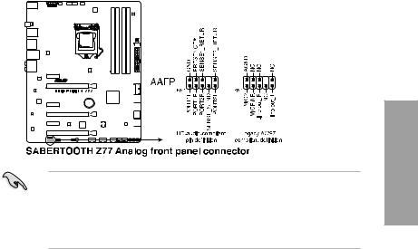
9.Front panel audio connector (10-1 pin AAFP)
This connector is for a chassis-mounted front panel audio I/O module that supports either HD Audio or legacy AC`97 audio standard. Connect one end of the front panel audio I/O module cable to this connector.
•We recommend that you connect a high-definition front panel audio module to this connector to avail of the motherboard’s high-definition audio capability.
•If you want to connect a high-definition front panel audio module to this connector, set the Front Panel Type item in the BIOS setup to [HD]; if you want to connect anAC’97 front panel audio module to this connector, set the item to [AC97]. By default, this connector is set to [HD].
Chapter 2

10.ATX power connectors (24-pin EATXPWR; 8-pin EATX12V)
These connectors are for ATX power supply plugs. The power supply plugs are designed to fit these connectors in only one orientation. Find the proper orientation and push down firmly until the connectors completely fit.
2 Chapter
•For a fully configured system, we recommend that you use a power supply unit (PSU) that complies withATX 12 V Specification 2.0 (or later version) and provides a minimum power of 350W.
•Do not forget to connect the 4-pin/8-pin EATX12 V power plug; otherwise, the system will not boot.
•Use of a PSU with a higher power output is recommended when configuring a system with more power-consuming devices. The system may become unstable or may not boot up if the power is inadequate.
•If you want to use two or more high-end PCI Express x16 cards, use a PSU with 1000W power or above to ensure the system stability.
•If you are uncertain about the minimum power supply requirement for your system, refer to the Recommended Power Supply Wattage Calculator at http://support.asus. com/PowerSupplyCalculator/PSCalculator.aspx?SLanguage=en-us for details.
|
2-24 |
Chapter 2: Hardware information |

11.System panel connector (20-8 pin PANEL)
This connector supports several chassis-mounted functions.
|
2 |
|||||||||||||||||||||||||||||||||||||||||||||||||||||||||||
|
power, and blinks when the system is in sleep mode. |
|||||||||||||||||||||||||||||||||||||||||||||||||||||||||||
|
• |
Chapter |
||||||||||||||||||||||||||||||||||||||||||||||||||||||||||
|
System power LED (2-pin PLED) |
|||||||||||||||||||||||||||||||||||||||||||||||||||||||||||
|
This 2-pin connector is for the system power LED. Connect the chassis power LED |
|||||||||||||||||||||||||||||||||||||||||||||||||||||||||||
|
cable to this connector. The system power LED lights up when you turn on the system |
|||||||||||||||||||||||||||||||||||||||||||||||||||||||||||
|
• |
Hard disk drive activity LED (2-pin IDE_LED) |
||||||||||||||||||||||||||||||||||||||||||||||||||||||||||
|
This 2-pin connector is for the HDD Activity LED. Connect the HDD Activity LED cable |
|||||||||||||||||||||||||||||||||||||||||||||||||||||||||||
|
to this connector. The IDE LED lights up or flashes when data is read from or written to |
|||||||||||||||||||||||||||||||||||||||||||||||||||||||||||
|
the HDD. |
|||||||||||||||||||||||||||||||||||||||||||||||||||||||||||
|
• |
System warning speaker (4-pin SPEAKER) |
||||||||||||||||||||||||||||||||||||||||||||||||||||||||||
|
This 4-pin connector is for the chassis-mounted system warning speaker. The speaker |
|||||||||||||||||||||||||||||||||||||||||||||||||||||||||||
|
allows you to hear system beeps and warnings. |
|||||||||||||||||||||||||||||||||||||||||||||||||||||||||||
|
• |
ATX power button/soft-off button (2-pin PWRSW) |
||||||||||||||||||||||||||||||||||||||||||||||||||||||||||
|
This connector is for the system power button. Pressing the power button turns the |
|||||||||||||||||||||||||||||||||||||||||||||||||||||||||||
|
system on or puts the system in sleep or soft-off mode depending on the BIOS settings. |
|||||||||||||||||||||||||||||||||||||||||||||||||||||||||||
|
Pressing the power switch for more than four seconds while the system is ON turns the |
|||||||||||||||||||||||||||||||||||||||||||||||||||||||||||
|
system OFF. |
|||||||||||||||||||||||||||||||||||||||||||||||||||||||||||
|
• |
Reset button (2-pin RESET) |
||||||||||||||||||||||||||||||||||||||||||||||||||||||||||
|
This 2-pin connector is for the chassis-mounted reset button for system reboot without |
|||||||||||||||||||||||||||||||||||||||||||||||||||||||||||
|
turning off the system power. |

2.3Building your computer system
2.3.1Additional tools and components to build a PC system
2 Chapter
|
1 bag of screws |
Philips (cross) screwdriver |
|
PC chassis |
Power supply unit |
|
Intel LGA 1155 CPU |
Intel LGA 1155 compatible CPU Fan |
|
DIMM |
SATA hard disk drive |
|
SATA optical disc drive (optional) |
Graphics card (optional) |
The tools and components in the table above are not included in the motherboard package.
|
2-26 |
Chapter 2: Hardware information |

2.3.2CPU installation
Please note the order in opening/ closing the double latch. Follow the instructions printed on the metal sealing hatch or the illustrations shown below in this manual. The plastic cap will pop up automatically once the CPU is in place and the hatch properly sealed down.
1

A
B
Chapter 2

|
2-28 |
Chapter 2: Hardware information |

2.3.3CPU heatsink and fan assembly installation
Apply the Thermal Interface Material to the CPU heatsink and CPU before you install the heatsink and fan if necessary.
To install the CPU heatsink and fan assembly
|
1 |
A |
2 |
|
B |
B |
|
|
A |
||
Chapter 2

2.3.4DIMM installation
1
2
2 Chapter
3
To remove a DIMM
B
A
|
2-30 |
Chapter 2: Hardware information |
 Loading…