-
Contents
-
Table of Contents
-
Bookmarks
Quick Links
Related Manuals for ASROCK B560 PRO4
Summary of Contents for ASROCK B560 PRO4
-
Page 2
(including damages for loss of profits, loss of business, loss of data, interruption of business and the like), even if ASRock has been advised of the possibility of such damages arising from any defect or error in the documentation or product. -
Page 3
If you require assistance please call ASRock Tel : +886-2-28965588 ext.123 (Standard International call charges apply) The terms HDMI®… -
Page 4
ES OF ANY KIND WHETHER UNDER THIS AGREEMENT OR OTHERWISE, EVEN IF INTEL HAS BEEN ADVISED OF THE POSSIBILITY OF SUCH DAMAGES. LICENSE TO USE COMMENTS AND SUGGESTIONS. This Agreement does NOT obligate Licensee to provide Intel with comments or suggestions regarding the Software. However, if Licensee provides Intel with comments or suggestions for the modification, correction, improvement or enhancement of (a) the Software or (b) Intel products or processes that work with the Software, Licensee grants to Intel a non-exclusive, worldwide,… -
Page 5: Table Of Contents
Installation Guide M.2_SSD (NGFF) Module Installation Guide (M2_1) 2.10 M.2_SSD (NGFF) Module Installation Guide (M2_2) 2.11 M.2_SSD (NGFF) Module Installation Guide (M2_3) Chapter 3 Software and Utilities Operation Installing Drivers ASRock Motherboard Utility (A-Tuning) ASRock Live Update & APP Shop…
-
Page 6
3.3.1 UI Overview 3.3.2 Apps 3.3.3 BIOS & Drivers 3.3.4 Setting Nahimic Audio ASRock Polychrome SYNC Chapter 4 UEFI SETUP UTILITY Introduction EZ Mode Advanced Mode 4.3.1 UEFI Menu Bar 4.3.2 Navigation Keys Main Screen OC Tweaker Screen Advanced Screen 4.6.1 CPU Configuration… -
Page 7
Security Screen 4.10 Boot Screen 4.11 Exit Screen… -
Page 9: Chapter 1 Introduction
ASRock’s website without further notice. If you require technical support related to this motherboard, please visit our website for specific information about the model you are using. You may find the latest VGA cards and CPU support list on ASRock’s website as well. ASRock website http://www.asrock.com.
-
Page 10: Specifications
Gen Intel® Core (i9/i7) support DDR4 up to 2933; Core (i5/i3), Pentium® and Celeron® support DDR4 up to 2666. * Please refer to Memory Support List on ASRock’s website for more information. (http://www.asrock.com/) • Supports ECC UDIMM memory modules (operate in non- ECC mode) • Max.
-
Page 11
B560 Pro4 Gen Intel® Core Processors Expansion Slot • 2 x PCI Express x16 Slots (PCIE1/PCIE3: single at Gen4x16 (PCIE1); dual at Gen4x16 (PCIE1) / Gen3x2 (PCIE3))* Gen Intel® Core Processors • 2 x PCI Express x16 Slots (PCIE1/PCIE3: single at Gen3x16 (PCIE1);… -
Page 12
• 1 x M.2 Socket (M2_3), supports M Key type 2280/22110 M.2 SATA3 6.0 Gb/s module and M.2 PCI Express module up to Gen3 x2 (16 Gb/s)** ** Supports Intel® Optane Technology (M2_2) ** Supports NVMe SSD as boot disks ** Supports ASRock U.2 Kit… -
Page 13
B560 Pro4 Connector • 1 x COM Port Header • 1 x SPI TPM Header • 1 x Chassis Intrusion and Speaker Header • 2 x RGB LED Headers * Support in total up to 12V/3A, 36W LED Strip • 2 x Addressable LED Headers * Support in total up to 5V/3A, 15W LED Strip • 1 x CPU Fan Connector (4-pin) -
Page 14
• ErP/EuP ready (ErP/EuP ready power supply is required) * For detailed product information, please visit our website: http://www.asrock.com Please realize that there is a certain risk involved with overclocking, including adjusting the setting in the BIOS, applying Untied Overclocking Technology, or using third-party overclocking tools. -
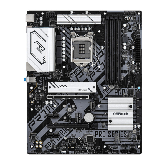
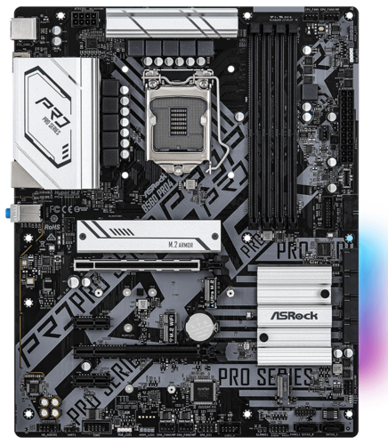
Page 15: Motherboard Layout
B560 Pro4 1.3 Motherboard Layout CPU_FAN1 CPU_FAN2/WP ATX12V1 USB 3.2 Gen1 T: USB3_3 B: USB3_4 USB 3.2 Gen1 Top: T: USB3_1 RJ-45 B: USB3_2 CHA_FAN1/WP C 10 PCIE1 C 14 C 13 C 12 C 11 Intel B560 PCIE2 CMOS…
-
Page 16
No. Description ATX 12V Power Connector (ATX12V1) 2 x 288-pin DDR4 DIMM Slots (DDR4_A1, DDR4_B1) 2 x 288-pin DDR4 DIMM Slots (DDR4_A2, DDR4_B2) CPU Fan Connector (CPU_FAN1) CPU/Water Pump Fan Connector (CPU_FAN2/WP) Addressable LED Header (ADDR_LED2) RGB LED Header (RGB_LED2) Chassis/Water Pump Fan Connector (CHA_FAN5/WP) ATX Power Connector (ATXPWR1) Front Panel Type C USB 3.2 Gen1 Header (USB31_TC_1) -
Page 17: I/O Panel
B560 Pro4 1.4 I/O Panel No. Description No. Description USB 2.0 Ports (USB1_2) USB 3.2 Gen1 Ports (USB3_1_2) LAN RJ-45 Port* USB 3.2 Gen1 Ports (USB3_3_4) Line In (Light Blue)** DisplayPort 1.4 Front Speaker (Lime)** HDMI Port Microphone (Pink)** PS/2 Mouse/Keyboard Port * There are two LEDs on each LAN port.
-
Page 18: Chapter 2 Installation
Chapter 2 Installation This is an ATX form factor motherboard. Before you install the motherboard, study the configuration of your chassis to ensure that the motherboard fits into it. Pre-installation Precautions Take note of the following precautions before you install motherboard components or change any motherboard settings.
-
Page 19: Installing The Cpu
B560 Pro4 2.1 Installing the CPU 1. Before you insert the 1200-Pin CPU into the socket, please check if the PnP cap is on the socket, if the CPU surface is unclean, or if there are any bent pins in the socket. Do not force to insert the CPU into the socket if above situation is found.
-
Page 21
B560 Pro4 Please save and replace the cover if the processor is removed. The cover must be placed if you wish to return the motherboard for after service. -
Page 22: Installing The Cpu Fan And Heatsink
2.2 Installing the CPU Fan and Heatsink…
-
Page 23: Installing Memory Modules (Dimm)
B560 Pro4 2.3 Installing Memory Modules (DIMM) This motherboard provides four 288-pin DDR4 (Double Data Rate 4) DIMM slots, and supports Dual Channel Memory Technology. 1. For dual channel configuration, you always need to install identical (the same brand, speed, size and chip-type) DDR4 DIMM pairs.
-
Page 25: Expansion Slots (Pci Express Slots)
B560 Pro4 2.4 Expansion Slots (PCI Express Slots) There are 4 PCI Express slots on the motherboard. Before installing an expansion card, please make sure that the power supply is switched off or the power cord is unplugged. Please read the documentation of the expansion card and make necessary hardware settings for the card before you start the installation.
-
Page 26: Jumpers Setup
2.5 Jumpers Setup The illustration shows how jumpers are setup. When the jumper cap is placed on the pins, the jumper is “Short”. If no jumper cap is placed on the pins, the jumper is “Open”. Clear CMOS Jumper (CLRMOS1) 2-pin Jumper (see p.7, No.
-
Page 27: Onboard Headers And Connectors
B560 Pro4 2.6 Onboard Headers and Connectors Onboard headers and connectors are NOT jumpers. Do NOT place jumper caps over these headers and connectors. Placing jumper caps over the headers and connectors will cause permanent damage to the motherboard. System Panel Header…
-
Page 28
Chassis Intrusion and Please connect the SPEAKER DUMMY Speaker Header chassis intrusion and the DUMMY (7-pin SPK_CI1) chassis speaker to this (see p.7, No. 25) header. SIGNAL DUMMY Serial ATA3 Connectors These six SATA3 Vertical: connectors support SATA (SATA3_0: data cables for internal see p.7, No. -
Page 29
B560 Pro4 USB 3.2 Gen1 Headers There are two headers on Vbus Vbus Vbus IntA_PB_SSRX- Vertical: this motherboard. Each IntA_PA_SSRX- IntA_PB_SSRX+ IntA_PA_SSRX+ (19-pin USB3_5_6) USB 3.2 Gen1 header can IntA_PB_SSTX- IntA_PA_SSTX- IntA_PB_SSTX+ (see p.7, No. 12) support two ports. IntA_PA_SSTX+… -
Page 30
Chassis/Water Pump Fan This motherboard provides Connectors five 4-Pin water cooling (4-pin CHA_FAN1/WP) chassis fan connectors. If FAN_SPEED_CONTROL FAN_SPEED (see p.7, No. 32) you plan to connect a 3-Pin FAN_VOLTAGE chassis water cooler fan, (4-pin CHA_FAN2/WP) please connect it to Pin 1-3. (see p.7, No. -
Page 31
B560 Pro4 ATX 12V Power This motherboard provides Connector an 8-pin ATX 12V power (8-pin ATX12V1) connector. To use a 4-pin (see p.7, No. 1) ATX power supply, please plug it along Pin 1 and Pin *Warning: Please make sure that the power cable connected is for the CPU and not the graphics card. -
Page 32
RGB LED Headers RGB headers are used to connect (4-pin RGB_LED1) RGB LED extension cables which 12V G R (see p.7, No. 29) allow users to choose from various LED lighting effects. Caution: Never install the (4-pin RGB_LED2) RGB LED cable in the wrong (see p.7, No. -
Page 33: Post Status Checker
B560 Pro4 2.7 Post Status Checker Post Status Checker (PSC) diagnoses the computer when users power on the machine. It emits a red light to indicate whether the CPU, memory, VGA or stor- age is dysfunctional. The lights go off if the four mentioned above are functioning…
-
Page 34: Wifi/Bt Module And Intel® Cnvi (Integrated Wifi/Bt) Installation Guide
2.8 M.2 WiFi/BT Module and Intel® CNVi (Integrated WiFi/BT) Installation Guide The M.2, also known as the Next Generation Form Factor (NGFF), is a small size and versatile card edge connector that aims to replace mPCIe and mSATA. The M.2 Socket (Key E) supports type 2230 WiFi/BT module and Intel®…
-
Page 35
B560 Pro4 Step 3 Gently insert the WiFi/BT module or Intel® CNVi (Integrated WiFi/ BT) into the M.2 slot. Please be aware that the module only fits in one orientation. Step 4 Tighten the screw with a screwdriver to secure the module into place. -
Page 36
2.9 M.2_SSD (NGFF) Module Installation Guide (M2_1) The M.2, also known as the Next Generation Form Factor (NGFF), is a small size and versatile card edge connector that aims to replace mPCIe and mSATA. The Hyper M.2 Socket (M2_1) supports M Key type 2242/2260/2280 M.2 PCI Express module up to Gen4x4 (64 Gb/s) (Only supported with 11 Gen Intel®… -
Page 37
B560 Pro4 Step 4 Prepare the M.2 standoff that comes with the package. Then hand tighten the standoff into the desired nut location on the motherboard. Align and gently insert the M.2 (NGFF) SSD module into the M.2 slot. Please be aware that the M.2 (NGFF) SSD… -
Page 38
XP941-512G (MZHPU512HCGL) SanDisk PCIe SD6PP4M-128G SanDisk PCIe SD6PP4M-256G TEAM PCIe3 x4 TM8FP2240G0C101 TEAM PCIe3 x4 TM8FP2480GC110 PCIe3 x4 WDS256G1X0C-00ENX0 (NVME) PCIe3 x4 WDS512G1X0C-00ENX0 (NVME) For the latest updates of M.2_SSD (NFGG) module support list, please visit our website for details: http://www.asrock.com… -
Page 39
B560 Pro4 2.10 M.2_SSD (NGFF) Module Installation Guide (M2_2) The M.2, also known as the Next Generation Form Factor (NGFF), is a small size and versatile card edge connector that aims to replace mPCIe and mSATA. The Ultra M.2 Socket (M2_2) supports M Key type 2242/2260/2280 M.2 PCI Express module up to Gen3 x4 (32 Gb/s). -
Page 40
Step 3 Move the standoff based on the module type and length . The standoff is placed at the nut location C by default. Skip Step 3 and 4 and go straight to Step 5 if you are going to use the default nut. Otherwise, release the standoff by hand. -
Page 41
B560 Pro4 M.2_SSD (NGFF) Module Support List (M2_2) Vendor Interface ADATA PCIe3 x4 ASX7000NP-128GT-C ADATA PCIe3 x4 ASX8000NP-256GM-C ADATA PCIe3 x4 ASX7000NP-256GT-C ADATA PCIe3 x4 ASX8000NP-512GM-C ADATA PCIe3 x4 ASX7000NP-512GT-C Apacer PCIe3 x4 AP240GZ280 Corsair PCIe3 x4 CSSD-F240GBMP500 Intel PCIe3 x4… -
Page 42: M.2_Ssd (Ngff) Module Installation Guide (M2_3)
2.11 M.2_SSD (NGFF) Module Installation Guide (M2_3) The M.2, also known as the Next Generation Form Factor (NGFF), is a small size and versatile card edge connector that aims to replace mPCIe and mSATA. The M.2 Socket (M2_3) supportsM Key type 2280/22110 M.2 SATA3 6.0 Gb/s module and M.2 PCI Express module up to Gen3 x2 (16 Gb/s).
-
Page 43
B560 Pro4 Step 3 Move the standoff based on the module type and length. The standoff is placed at the nut location A by default. Skip Step 3 and 4 and go straight to Step 5 if you are going to use the default nut. -
Page 44
TS256GMTS400 Transcend SATA3 TS512GMTS600 Transcend SATA3 TS512GMTS800 V-Color SATA3 VLM100-120G-2280B-RD V-Color SATA3 VLM100-240G-2280RGB V-Color SATA3 VSM100-240G-2280 V-Color SATA3 VLM100-240G-2280B-RD SATA3 WDS100T1B0B-00AS40 SATA3 WDS240G1G0B-00RC30 For the latest updates of M.2_SSD (NFGG) module support list, please visit our website for details: http://www.asrock.com… -
Page 45: Chapter 3 Software And Utilities Operation
B560 Pro4 Chapter 3 Software and Utilities Operation 3.1 Installing Drivers The Support CD that comes with the motherboard contains necessary drivers and useful utilities that enhance the motherboard’s features. Running The Support CD To begin using the support CD, insert the CD into your CD-ROM drive. The CD automatically displays the Main Menu if “AUTORUN”…
-
Page 46: Asrock Motherboard Utility (A-Tuning)
3.2.1 Installing ASRock Motherboard Utility (A-Tuning) ASRock Motherboard Utility (A-Tuning) can be downloaded from ASRock Live Update & APP Shop. After the installation, you will find the icon “ASRock Mother- board Utility (A-Tuning)“ on your desktop. Double-click the “ASRock Motherboard Utility (A-Tuning)“…
-
Page 47
B560 Pro4 OC Tweaker Configurations for overclocking the system. System Info View information about the system. *The System Browser tab may not appear for certain models. -
Page 48
Settings Configure ASRock Motherboard Utility (A-Tuning). Click to select «Auto run at Windows Startup» if you want ASRock Motherboard Utility (A-Tuning) to be launched when you start up the Windows operating system. -
Page 49: Asrock Live Update & App Shop
Double-click on your desktop to access ASRock Live Update & APP Shop utility. *You need to be connected to the Internet to download apps from the ASRock Live Update & APP Shop. 3.3.1 UI Overview Category Panel Hot News…
-
Page 50: Apps
3.3.2 Apps When the «Apps» tab is selected, you will see all the available apps on screen for you to download. Installing an App Step 1 Find the app you want to install. The most recommended app appears on the left side of the screen. The other various apps are shown on the right.
-
Page 51
B560 Pro4 Step 3 If you want to install the app, click on the red icon to start downloading. Step 4 When installation completes, you can find the green «Installed» icon appears on the upper right corner. To uninstall it, simply click on the trash can icon… -
Page 52
Upgrading an App You can only upgrade the apps you have already installed. When there is an available new version for your app, you will find the mark of «New Version» appears below the installed app icon. Step 1 Click on the app icon to see more details. Step 2 Click on the yellow icon to start upgrading. -
Page 53: Bios & Drivers
B560 Pro4 3.3.3 BIOS & Drivers Installing BIOS or Drivers When the «BIOS & Drivers» tab is selected, you will see a list of recommended or critical updates for the BIOS or drivers. Please update them all soon. Step 1 Please check the item information before update.
-
Page 54: Setting
3.3.4 Setting In the «Setting» page, you can change the language, select the server location, and determine if you want to automatically run the ASRock Live Update & APP Shop on Windows startup.
-
Page 55: Nahimic Audio
B560 Pro4 3.4 Nahimic Audio Nahimic audio software provides an incredible high definition sound technology which boosts the audio and voice performance of your system. Nahimic Audio interface is composed of four tabs : Audio, Microphone, Sound Tracker and Settings.
-
Page 56: Asrock Polychrome Sync
3.5 ASRock Polychrome SYNC ASRock Polychrome SYNC is a lighting control utility specifically designed for unique indi- viduals with sophisticated tastes to build their own stylish colorful lighting system. Simply by connecting the LED strip, you can customize various lighting schemes and patterns, including Static, Breathing, Strobe, Cycling, Music, Wave and more.
-
Page 57
B560 Pro4 Connecting the Addressable RGB LED Strip Connect your Addressable RGB LED strips to the Addressable LED Headers (ADDR_LED1 / ADDR_LED2) on the motherboard. ADDR_LED2 ADDR_LED1 DO_ADDR VOUT 1. Never install the RGB LED cable in the wrong orientation; otherwise, the cable may be damaged. -
Page 58
ASRock Polychrome SYNC Utility Now you can adjust the RGB LED color through the ASRock Polychrome SYNC Utility. Download this utility from the ASRock Live Update & APP Shop and start coloring your PC style your way! Drag the tab to customize your preference. -
Page 59: Chapter 4 Uefi Setup Utility
B560 Pro4 Chapter 4 UEFI SETUP UTILITY 4.1 Introduction This section explains how to use the UEFI SETUP UTILITY to configure your system. You may run the UEFI SETUP UTILITY by pressing <F2> or <Del> right after you power on the computer, otherwise, the Power-On-Self-Test (POST) will continue with its test routines.
-
Page 60: Ez Mode
4.2 EZ Mode The EZ Mode screen appears when you enter the BIOS setup program by default. EZ mode is a dashboard which contains multiple readings of the system’s current status. You can check the most crucial information of your system, such as CPU speed, DRAM frequency, SATA information, fan speed, etc.
-
Page 61: Advanced Mode
B560 Pro4 4.3 Advanced Mode The Advanced Mode provides more options to configure the BIOS settings. Refer to the following sections for the detailed configurations. To access the EZ Mode, press <F6> or click the «EZ Mode» button at the upper right corner of the screen.
-
Page 62: Navigation Keys
4.3.2 Navigation Keys Use < > key or < > key to choose among the selections on the menu bar, and use < > key or < > key to move the cursor up or down to select items, then press <Enter>…
-
Page 63: Main Screen
B560 Pro4 4.4 Main Screen When you enter the UEFI SETUP UTILITY, the Main screen will appear and display the system overview. The availability and location of BIOS settings can be different for different models and BIOS versions. My Favorite…
-
Page 64: Oc Tweaker Screen
4.5 OC Tweaker Screen In the OC Tweaker screen, you can set up overclocking features. Because the UEFI software is constantly being updated, the following UEFI setup screens and descriptions are for reference purpose only, and they may not exactly match what you see on your screen.
-
Page 65
B560 Pro4 maximum possible ratio for SSE workloads. CPU Cache Ratio The CPU Internal Bus Speed Ratio. The maximum should be the same as the CPU Ratio. BCLK Spread Spectrum Mode Enable Spread Spectrum to reduce electromagnetic interference for passing EMI tests. -
Page 66
Intel Thermal Velocity Boost Voltage Optimizations This service controls thermal based voltage optimizations for processors that implment the Intel Thermal Velocity Boost (TVB) feature. Dual Tau Boost Enable Dual Tau Boost feature. This is only applicable for CMLS 35W/65W/125W skus. This item is only supported with processors with Config TDP support. Long Duration Power Limit Configure Package Power Limit 1 in watts. -
Page 67
B560 Pro4 DRAM Timing Configuration DRAM Frequency If [Auto] is selected, the motherboard will detect the memory module(s) inserted and assign the appropriate frequency automatically. Primary Timing CAS# Latency (tCL) The time between sending a column address to the memory and the beginning of the data in response. -
Page 68
rank. Write to Read Delay (tWTR_L) The number of clocks between the last valid write operation and the next read command to the same internal bank. Write to Read Delay (tWTR_S) The number of clocks between the last valid write operation and the next read command to the same internal bank. -
Page 69
B560 Pro4 tRDWR_sg Configure between module read to write delay. tRDWR_dg Configure between module read to write delay. tRDWR_dr Configure between module read to write delay. tRDWR_dd Configure between module read to write delay. tWRRD_sg Configure between module write to read delay. -
Page 70
Initial RTL (A1 Rank1) Configure round trip latency initial value. Initial RTL (A1 Rank2) Configure round trip latency initial value. Initial RTL (A2 Rank1) Configure round trip latency initial value. Initial RTL (A2 Rank2) Configure round trip latency initial value. Initial RTL (B1 Rank1) Configure round trip latency initial value. -
Page 71
B560 Pro4 RTL (B2 Rank1) Configure round trip latency. RTL (B2 Rank2) Configure round trip latency. IOL Init Value Configure IO latency init value for IO latency training. IOL (A1 Rank1) Configure IO latency. IOL (A1 Rank2) Configure IO latency. -
Page 72
ODT Setting Dimm ODT Training ODT values will be optimized by Dimm On-Die Termination Training. ODT WR (A1) Configure the memory on die termination resistors’ WR for channel A1. ODT WR (A2) Configure the memory on die termination resistors’ WR for channel A2. ODT WR (B1) Configure the memory on die termination resistors’ WR for channel B1. -
Page 73
Configure Dll Bandwidth 3 (1867 MHz) to maximize the performance of intergrated memory controller. Advanced Setting ASRock Timing Optimization Configure the fast path through the MRC. ASRock Second Timing Optimization Configure the second fast path through the MRC. Memory Training Mode Configure the Training Memory Mode. Realtime Memory Timing Configure the realtime memory timings. -
Page 74
MRC Fast Boot Enable Memory Fast Boot to skip DRAM memory training for booting faster. Voltage Configuration Voltage Mode [OC]: Larger range voltage for overclocking. [STABLE]: Smaller range voltage for stable system. CPU Core/Cache Voltage Input voltage for the processor by the external voltage regulator. Core/Cache V/F Curve Configure CPU Core/Cache Voltage/Frequency Curve. -
Page 75
B560 Pro4 CPU Standby Voltage Configure the voltage for the CPU Standby. Save User Default Type a profile name and press enter to save your settings as user default. Load User Default Load previously saved user defaults. Save User UEFI Setup Profile to Disk It helps you to save current UEFI settings as an user profile to disk. -
Page 76: Advanced Screen
4.6 Advanced Screen In this section, you may set the configurations for the following items: CPU Configuration, Chipset Configuration, Storage Configuration, Super IO Configuration, ACPI Configuration, USB Configuration and Trusted Computing. Setting wrong values in this section may cause the system to malfunction. UEFI Configuration UEFI Setup Style Select the default mode when entering the UEFI setup utility.
-
Page 77: Cpu Configuration
B560 Pro4 4.6.1 CPU Configuration Intel Hyper Threading Technology Intel Hyper Threading Technology allows multiple threads to run on each core, so that the overall performance on threaded software is improved. Active Processor Cores Select the number of cores to enable in each processor package.
-
Page 78
Package C State Support Enable CPU, PCIe, Memory, Graphics C State Support for power saving. CFG Lock This item allows you to disable or enable the CFG Lock. CPU Thermal Throttling Enable CPU internal thermal control mechanisms to keep the CPU from overheat- ing. -
Page 79: Chipset Configuration
B560 Pro4 4.6.2 Chipset Configuration Primary Graphics Adapter Select a primary VGA. Above 4G Decoding Enable or disable 64bit capable Devices to be decoded in Above 4G Address Space (only if the system supports 64 bit PCI decoding). VT-d Intel® Virtualization Technology for Directed I/O helps your virtual machine…
-
Page 80
PCIE2 Link Speed Select the link speed for PCIE2. PCIE3 Link Speed Select the link speed for PCIE3. PCIE4 Link Speed Select the link speed for PCIE4. PCI Express Native Control Select Enable for enhanced PCI Express power saving in OS. PCIE ASPM Support This option enables/disables the ASPM support for all CPU downstream devices. -
Page 81
B560 Pro4 Front Panel Enable/disable front panel HD audio. Onboard HDMI HD Audio Enable audio for the onboard digital outputs. Onboard WAN Device Use this item to enable or disable the onboard WAN device. WAN Radio Enable/disable the WiFi module’s connectivity. -
Page 82: Storage Configuration
4.6.3 Storage Configuration SATA Controller(s) Enable/disable the SATA controllers. SATA Mode Selection AHCI: Supports new features that improve performance. SATA Aggressive Link Power Management SATA Aggressive Link Power Management allows SATA devices to enter a low power state during periods of inactivity to save power. It is only supported by AHCI mode.
-
Page 83: Super Io Configuration
B560 Pro4 4.6.4 Super IO Configuration Serial Port Enable or disable the Serial port. Serial Port Address Select the address of the Serial port. PS2 Y-Cable Enable the PS2 Y-Cable or set this option to Auto.
-
Page 84: Acpi Configuration
4.6.5 ACPI Configuration Suspend to RAM Select disable for ACPI suspend type S1. It is recommended to select auto for ACPI S3 power saving. PS/2 Keyboard S4/S5 Wakeup Support Allow the system to be waked up by a PS/2 Keyboard in S4/S5. PCIE Devices Power On Allow the system to be waked up by a PCIE device and enable wake on LAN.
-
Page 85: Usb Configuration
B560 Pro4 4.6.6 USB Configuration Legacy USB Support Enable or disable Legacy OS Support for USB 2.0 devices. If you encounter USB compatibility issues it is recommended to disable legacy USB support. Select UEFI Setup Only to support USB devices under the UEFI setup and Windows/Linux operating systems only.
-
Page 86: Trusted Computing
4.6.7 Trusted Computing Security Device Support Enable or disable BIOS support for security device.
-
Page 87: Tools
ASRock Polychrome RGB Select LED lighting color. UEFI Tech Service Contact ASRock Tech Service if you are having trouble with your PC. Please setup network configuration before using UEFI Tech Service. SSD Secure Erase Tool All the SSD’s listed that supports Secure Erase function.
-
Page 88
Flash. *For BIOS backup and recovery purpose, it is recommended to plug in your USB pen drive before using this function. Network Configuration Use this to configure internet connection settings for Internet Flash. Internet Setting Enable or disable sound effects in the setup utility. UEFI Download Server Select a server to download the UEFI firmware. -
Page 89: Hardware Health Event Monitoring Screen
B560 Pro4 4.8 Hardware Health Event Monitoring Screen This section allows you to monitor the status of the hardware on your system, including the parameters of the CPU temperature, motherboard temperature, fan speed and voltage. Fan Tuning Measure Fan Min Duty Cycle.
-
Page 90
CPU Fan 2 Control Mode Select DC/PWM mode for CPU Fan 2. CPU Fan 2 Setting Select a fan mode for CPU Fan, or choose Customize to set 5 CPU temperatures and assign a respective fan speed for each temperature. CPU Fan 2 Temp Source Select a fan temperature source for CPU Fan 2. -
Page 91
B560 Pro4 Chassis Fan 2 Setting Select a fan mode for Chassis Fan 2, or choose Customize to set 5 CPU temperatures and assign a respective fan speed for each temperature. Chassis Fan 2 Temp Source Select a fan temperature source for Chassis Fan 2. -
Page 92
Chassis Fan 4 Setting Select a fan mode for Chassis Fan 4, or choose Customize to set 5 CPU temperatures and assign a respective fan speed for each temperature. Chassis Fan 4 Temp Source Select a fan temperature source for Chassis Fan 4. Chassis Fan 4 Step Up Set the value of Chassis Fan 4 Step Up. -
Page 93
B560 Pro4 4.9 Security Screen In this section you may set or change the supervisor/user password for the system. You may also clear the user password. Supervisor Password Set or change the password for the administrator account. Only the administrator has authority to change the settings in the UEFI Setup Utility. -
Page 94
4.10 Boot Screen This section displays the available devices on your system for you to configure the boot settings and the boot priority. Fast Boot Fast Boot minimizes your computer’s boot time. In fast mode you may not boot from an USB storage device. The VBIOS must support UEFI GOP if you are using an external graphics card. -
Page 95
B560 Pro4 Full Screen Logo Enable to display the boot logo or disable to show normal POST messages. AddOn ROM Display Enable AddOn ROM Display to see the AddOn ROM messages or configure the AddOn ROM if you’ve enabled Full Screen Logo. Disable for faster boot speed. -
Page 96
only to run those that support legacy option ROM only. Select Do not launch to not execute both legacy and UEFI option ROM. Other PCI Device ROM Priority For PCI devices other than Network. Mass storage or Video defines which OpROM to launch. -
Page 97
B560 Pro4 4.11 Exit Screen Save Changes and Exit When you select this option the following message, “Save configuration changes and exit setup?” will pop out. Select [OK] to save changes and exit the UEFI SETUP UTILITY. Discard Changes and Exit When you select this option the following message, “Discard changes and exit… -
Page 98
Contact Information If you need to contact ASRock or want to know more about ASRock, you’re welcome to visit ASRock’s website at http://www.asrock.com; or you may contact your dealer for further information. For technical questions, please submit a support request form at https://event.asrock.com/tsd.asp… -
Page 99
13848 Magnolia Ave, Chino, CA91710 Phone/Fax No: +1-909-590-8308/+1-909-590-1026 hereby declares that the product Product Name : Motherboard B560 Pro4 Model Number : Conforms to the following speci cations: FCC Part 15, Subpart B, Unintentional Radiators Supplementary Information: is device complies with part 15 of the FCC Rules. Operation is subject to the… -
Page 100
EU Declaration of Conformity For the following equipment: Motherboard (Product Name) B560 Pro4 / ASRock (Model Designation / Trade Name) ASRock Incorporation (Manufacturer Name) 2F., No.37, Sec. 2, Jhongyang S. Rd., Beitou District, Taipei City 112, Taiwan (R.O.C.) (Manufacturer Address) EMC —Directive 2014/30/EU (from April 20th, 2016)
Version 1.0
Published January 2021
Copyright©2021 ASRock INC. All rights reserved.
Copyright Notice:
No part of this documentation may be reproduced, transcribed, transmitted, or
translated in any language, in any form or by any means, except duplication of
documentation by the purchaser for backup purpose, without written consent of
ASRock Inc.
Products and corporate names appearing in this documentation may or may not
be registered trademarks or copyrights of their respective companies, and are used
only for identification or explanation and to the owners’ benefit, without intent to
infringe.
Disclaimer:
Specifications and information contained in this documentation are furnished for
informational use only and subject to change without notice, and should not be
constructed as a commitment by ASRock. ASRock assumes no responsibility for
any errors or omissions that may appear in this documentation.
With respect to the contents of this documentation, ASRock does not provide
warranty of any kind, either expressed or implied, including but not limited to
the implied warranties or conditions of merchantability or fitness for a particular
purpose.
In no event shall ASRock, its directors, officers, employees, or agents be liable for
any indirect, special, incidental, or consequential damages (including damages for
loss of profits, loss of business, loss of data, interruption of business and the like),
even if ASRock has been advised of the possibility of such damages arising from any
defect or error in the documentation or product.
This device complies with Part 15 of the FCC Rules. Operation is subject to the following
two conditions:
(1) this device may not cause harmful interference, and
(2) this device must accept any interference received, including interference that
may cause undesired operation.
CALIFORNIA, USA ONLY
The Lithium battery adopted on this motherboard contains Perchlorate, a toxic substance
controlled in Perchlorate Best Management Practices (BMP) regulations passed by the
California Legislature. When you discard the Lithium battery in California, USA, please
follow the related regulations in advance.
«Perchlorate Material-special handling may apply, see www.dtsc.ca.gov/hazardouswaste/
perchlorate»
ASRock Website: http://www.asrock.com
-
ASROCK 760GM-S3
AMD 760G + SB710 Chipsets760GM-S3w w w. a s ro ck.comDetail Specification Product Brief CPUMemoryExpansion SlotAudioLANRear Panel I/OConnectorBIOS FeatureSupport CDAccessoriesUnique FeatureHardware MonitorOSCertificationsThe specification is subject to change without notice. The brand and product names are trademarks o …
760GM-S3 Motherboard, 5
-
mikroElektronika DC MOTOR 2 click
2 32. Soldering the headers3. Plugging the board inOnce you have soldered the headers your board is ready to be placed into the desired mikroBUS™ socket. Make sure to align the cut in the lower-right part of the board with the markings on the silkscreen at the mikroBUS™ socket. If all the pins are aligned correctly …
DC MOTOR 2 click Motherboard, 2
-
Abit BG7ML
Copyright and Warranty Notice The information in this document is subject to change without notice and does not represent a commitment on part of the vendor, who assumes no liability or responsibility for any errors that may appear in this manual. No warranty or representation, either expressed or implied, is made wit …
BG7ML Motherboard, 96
-
ST STEVAL-IFS012V1
June 2010 Doc ID 15482 Rev 1 1/39UM0690User manualSTEVAL-IFS012V1 demonstration board formultiple temperature sensorsIntroductionThis user manual explains the functions of the multi-device temperature sensor demonstration board which is based on a motherboard and daughter card approach. The complete system consists of …
STEVAL-IFS012V1 Motherboard, 39
-
Texas Instruments CC85-CC2590EM Series
SWRU252B September 2012 CC85XXDK Quick Start Guide 1. Kit Contents The following items are included in the CC85XXDK: 2 x Purepath Wireless AudioEB 1 x CC Debugger 2 x CC85xxEM 2 x CC85xx-CC2590EM 2 x 2.4 GHz Antennas Cables Documentation The RF boards in this kit are FCC and IC certifi …
CC85-CC2590EM Series Motherboard, 7
-
ASROCK H310CM-HDVP
Version 1.0 Published July 2018 Copyright©2018 ASRock INC. All rights reserved.Copyright Notice:No part of this documentation may be reproduced, transcribed, transmitted, or translated in any language, in any form or by any means, except duplication of documentation by the purchaser for backup purpose, without written …
H310CM-HDVP Motherboard, 64
-
Lanner electronics AP-687VF
AP-687VF/F Single Board Computer for Slot 1 Processor The contents & information in this manual are subject to change without prior notice. For reference only. StockCheck.com …
AP-687VF Motherboard, 77
-
NXP Semiconductors FRDM-STBC-AGM04
Quick ReferenceFRDM-STBC-AGM04Sensor Toolbox Development Platform for MMA8652FC 3-axis digital accelerometer, FXAS21002C 3-axis digital angular rate gyroscope, and MAG3110 3-axis digital magnetometerSENSOR TOOLBOX SHIELD DEVELOPMENT BOARD …
FRDM-STBC-AGM04 Motherboard, 4
(Ocr-Read Summary of Contents of some pages of the ASROCK B560 PRO4 Document (Main Content), UPD: 02 April 2023)
-
45, 37 English B560 Pro4 Chapter 3 Software and Utilities Operation 3.1 Installing Drivers e Support CD that comes with the motherboard contains necessary drivers and useful utilities that enhance the motherboard’s features. Running The Support CD To begin using the support CD, insert the CD into your CD-ROM drive. e CD automatically displays the Main Menu if “AUTORUN” is enabled in your computer. If the Mai…
-
91, 83 English B560 Pro4 Chassis Fan 2 Setting Select a fan mode for Chassis Fan 2, or choose Customize to set 5 CPU temperatures and assign a respective fan speed for each temperature. Chassis Fan 2 Temp Source Select a fan temperature source for Chassis Fan 2. Chassis Fan 2 Step Up Set the value of Chassis Fan 2 Step Up. Chassis Fan 2 Step Down Set the value of Chassis Fan 2 Step Down. CHA_FAN3 / W_PUMP Switch Select Chassis Fan 3 or Water Pump mode. Chassis Fan 3 Control Mode Select PW…
-
35, 27 English B560 Pro4 A A 20 o Step 3 Gently insert the WiFi/BT module or Intel® CNVi (Integrated WiFi/ BT) into the M.2 slot. Please be aware that the module only ts in one orientation. A Step 4 Tighten the screw with a screwdriver to secure the module into place. Please do not overtighten the screw as this might damage the module.
… -
60, 52 English 4.2 EZ Mode e EZ Mode screen appears when you enter the BIOS setup program by default. EZ mode is a dashboard which contains multiple readings of the system’s current status. You can check the most crucial information of your system, such as CPU speed, DRAM frequency, SATA information, fan speed, etc. Press <F6> or click the «Advanced Mode» button at the upper right corner of t…
-
46, 38 English 3.2 ASRock Motherboard Utility (A-Tuning) ASRock Motherboard Utility (A-Tuning) is ASRock’s multi purpose soware suite with a new interface, more new features and improved utilities. 3.2.1 Installing ASRock Motherboard Utility (A-Tuning) ASRock Motherboard Utility (A-Tuning) can be downloaded from ASRock Live Update & APP Shop. Aer the installation, you will nd the icon “ASRock Mother- board Utility (A-Tuning)“ on your desktop. Double-click the “ASRo…
-
39, ASROCK B560 PRO4 31 English B560 Pro4 2.10 M.2_SSD (NGFF) Module Installation Guide (M2_2) e M.2, also known as the Next Generation Form Factor (NGFF), is a small size and versatile card edge connector that aims to replace mPCIe and mSATA. e Ultra M.2 Socket (M2_2) supports M Key type 2242/2260/2280 M.2 PCI Express module up to Gen3 x4 (32 Gb/s). Installing the M.2_SSD (NGFF) Module Step 1 Prepare a M.2_SSD (NGFF) module and the screw. 1 …
-
94, 86 English 4.10 Boot Screen is section displays the available devices on your system for you to congure the boot settings and the boot priority. Fast Boot Fast Boot minimizes your computer’s boot time. In fast mode you may not boot from an USB storage device. e VBIOS must support UEFI GOP if you are using an external graphics card. Please notice that Ultra Fast mode will boot so fast that the only way to ent…
-
99, DECLARATION OF CONFORMITY Per FCC Part 2 Section 2.1077(a) Responsible Party Name: ASRock Incorporation Address: 13848 Magnolia Ave, Chino, CA91710 +1-909-590-8308/+1-909-590-1026 Phone/FaxNo: hereby declares that the product Product Name : Motherboard Model Number : Conforms to the following specications: FCC Part 15, Subpart B, Unintentional Radiators …
-
71, 63 English B560 Pro4 RTL (B2 Rank1) Congure round trip latency. RTL (B2 Rank2) Congure round trip latency. IOL Init Value Congure IO latency init value for IO latency training. IOL (A1 Rank1) Congure IO latency. IOL (A1 Rank2) Congure IO latency. IOL (A2 Rank1) Congure IO latency. IOL (A2 Rank2) Congure IO latency. IOL (B1 Rank1) Congure IO latency. IOL (B1 Rank2) Congure IO latency. IOL (B2 Rank1) Congure IO latency. IOL (B2 …
-
59, 51 English B560 Pro4 Chapter 4 UEFI SETUP UTILITY 4.1 Introduction is section explains how to use the UEFI SETUP UTILITY to congure your system. You may run the UEFI SETUP UTILITY by pressing <F2> or <Del> right aer you power on the computer, otherwise, the Power-On-Self-Test (POST) will continue with its test routines. If you wish to enter the UEFI SETUP UTILITY aer POST, restart the system by…
-
87, 79 English B560 Pro4 4.7 Tools ASRock Polychrome RGB Select LED lighting color. UEFI Tech Service Contact ASRock Tech Service if you are having trouble with your PC. Please setup network conguration before using UEFI Tech Service. SSD Secure Erase Tool All the SSD’s listed that supports Secure Erase function. NVME Sanitization Tool Aer you Sanitize SSD, all user data will be permanently destroyed on the SSD and cannot be recovered. Instant Flash Save UEFI les…
-
88, 80 English Flash. *For BIOS backup and recovery purpose, it is recommended to plug in your USB pen drive before using this function. Network Conguration Use this to congure internet connection settings for Internet Flash. Internet Setting Enable or disable sound eects in the setup utility. UEFI Download Server Select a server to download the UEFI rmware.
… -
25, 17 English B560 Pro4 2.4 Expansion Slots (PCI Express Slots) ere are 4 PCI Express slots on the motherboard. PCIe slots: 11 th Gen Intel® Core TM Processors: PCIE1 (PCIe 4.0 x16 slot) is used for PCI Express x16 lane width graphics cards. PCIE2 (PCIe 3.0 x1 slot) is used for PCI Express x1 lane width cards. PCIE3 (PCIe 3.0 x16 slot) is used for PCI Express x2 lane width graphics cards. PCI…
-
63, 55 English B560 Pro4 4.4 Main Screen When you enter the UEFI SETUP UTILITY, the Main screen will appear and display the system overview. My Favorite Display your collection of BIOS items. Press F5 to add/remove your favorite items. e availability and location of BIOS settings can be dierent for dierent models and BIOS versions.
… -
18, 10 English is is an ATX form factor motherboard. Before you install the motherboard, study the conguration of your chassis to ensure that the motherboard ts into it. Pre-installation Precautions Take note of the following precautions before you install motherboard components or change any motherboard settings. • Make sure to unplug the power cord before installing or removing the motherboard components. Failure to do so may cause physical inj…
-
98, ASROCK B560 PRO4 Contact Information If you need to contact ASRock or want to know more about ASRock, you’re welcome to visit ASRock’s website at http://www.asrock.com; or you may contact your dealer for further information. For technical questions, please submit a support request form at https://event.asrock.com/tsd.asp ASRock Incorporation 2F., No.37, Sec. 2, Jhongyang S. Rd., Beitou District, Taipei City 112,…
Материнская плата ASRock B560 Pro4
LGA 1200, Intel B560, 4xDDR4-3200 МГц, 2xPCI-Ex16, 3xM.2, Standard-ATX
подробнее

112
Код товара: 4817715