-
Contents
-
Table of Contents
-
Bookmarks
Quick Links
970 Pro3
User Manual
Version 1.0
Published April 2012
Copyright©2012 ASRock INC. All rights reserved.
1
Related Manuals for ASROCK 970 Pro3
Summary of Contents for ASROCK 970 Pro3
-
Page 1: User Manual
970 Pro3 User Manual Version 1.0 Published April 2012 Copyright©2012 ASRock INC. All rights reserved.
-
Page 2: Copyright Notice
fi tness for a particular purpose. In no event shall ASRock, its directors, offi cers, employees, or agents be liable for any indirect, special, incidental, or consequential damages (including damages for loss of profi…
-
Page 3: Table Of Contents
Expansion Slots (PCI and PCI Express Slots) ……18 CrossFireX and Quad CrossFireX Operation Guide …. 19 Surround Display Information ………… 22 ASRock Smart Remote Installation Guide ……… 23 Jumpers Setup …………….25 Onboard Headers and Connectors ……..26 2.10 Serial ATA3 (SATA3) Hard Disks Installation ……
-
Page 4
3. UEFI SETUP UTILITY…………38 Introduction …………….38 3.1.1 UEFI Menu Bar …………..38 3.1.2 Navigation Keys …………… 39 Main Screen …………….40 OC Tweaker Screen…………..41 Advanced Screen …………..45 3.4.1 CPU Confi guration …………46 3.4.2 North Bridge Confi guration ……….47 3.4.3 South Bridge Confi… -
Page 5: Introduction
In case any modifi cations of this manual occur, the updated ver- sion will be available on ASRock website without further notice. You may fi nd the latest VGA cards and CPU support lists on ASRock website as well. ASRock website http://www.asrock.com…
-
Page 6: Specifi Cations
1.2 Specifications Platform — ATX Form Factor: 12.0-in x 8.2-in, 30.5 cm x 20.8 cm — All Solid Capacitor design — Support for Socket AM3+ processors — Support for Socket AM3 processors: AMD Phenom II X6 / X4 / X3 / X2 (except 920 / 940) / Athlon II X4 / X3 / X2 / Sempron processors — Supports 8-Core CPU — Supports UCC feature (Unlock CPU Core) (see CAUTION 1)
-
Page 7
— Supports jumperfree — SMBIOS 2.3.1 Support — CPU, VCCM, NB, SB Voltage Multi-adjustment Support CD — Drivers, Utilities, AntiVirus Software (Trial Version), CyberLink MediaEspresso 6.5 Trial, AMD OverDrive Utility, AMD Fusion, AMD Fusion Media Explorer, ASRock MAGIX Multimedia Suite — OEM… -
Page 8
— FCC, CE, WHQL — ErP/EuP Ready (ErP/EuP ready power supply is required) (see CAUTION 21) * For detailed product information, please visit our website: http://www.asrock.com WARNING Please realize that there is a certain risk involved with overclocking, including adjusting the setting in the BIOS, applying Untied Overclocking Technology, or using the third-party over- clocking tools. -
Page 9
CAUTION! ASRock UCC (Unlock CPU Core) feature simplifi es AMD CPU activa- tion. As long as a simple switch of the UEFI option “ASRock UCC”, you can unlock the extra CPU core to enjoy an instant performance boost. When UCC feature is enabled, the dual-core or triple-core CPU will boost… -
Page 10
Real-Time Analysis of Your Data: With the status window, you can easily recognize which data streams you are currently transfer- ring. 13. ASRock XFast RAM is a new function that is included into ASRock Ex- treme Tuning Utility (AXTU). It fully utilizes the memory space that cannot ®… -
Page 11
Please note that you must be running on a DHCP confi gured computer in order to enable this function. 17. ASRock On/Off Play Technology allows users to enjoy the great audio ex- perience from the portable audio devices, such like MP3 player or mobile phone to your PC, even when the PC is turned off (or in ACPI S5 mode)! This motherboard also provides a free 3.5mm audio cable (optional) that… -
Page 12: Motherboard Layout
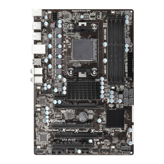
Chipset PCIE1 PCIE2 CMOS BATTERY SB950 AUDIO CODEC Chipset PCI1 ErP/EuP Ready Fast LAN Fast RAM Fast USB PCIE3 Super 970 Pro3 RoHS 32Mb BIOS SATA3_2 PCI2 CLRCMOS1 SPEAKER1 PANEL 1 USB_6_7 COM1 USB_10_11 USB_8_9 PLED PWRBTN HD_AUDIO1 CHA_FAN2 SATA3_1…
-
Page 13: I/O Panel
1.4 I/O Panel PS/2 Mouse Port (Green) Microphone (Pink) LAN RJ-45 Port USB 3.0 Port (USB3_0_1) Side Speaker (Gray) USB 2.0 Port (USB_4_5) Rear Speaker (Black) USB 2.0 Port (USB_2_3) Central / Bass (Orange) USB 2.0 Port (USB_0_1) Line In (Light Blue) PS/2 Keyboard Port (Purple) ** 7 Front Speaker (Lime)
-
Page 14: Installation
2. Installation This is an ATX form factor (12.0-in x 8.2-in, 30.5 cm x 20.8 cm) motherboard. Before you install the motherboard, study the confi guration of your chassis to ensure that the motherboard fi ts into it. Pre-installation Precautions Take note of the following precautions before you install motherboard components or change any motherboard settings.
-
Page 15: Cpu Installation
2.1 CPU Installation Step 1. Unlock the socket by lifting the lever up to a 90 angle. Step 2. Position the CPU directly above the socket such that the CPU corner with the golden triangle matches the socket corner with a small triangle. Step 3.
-
Page 16: Installation Of Memory Modules (Dimm)
2.3 Installation of Memory Modules (DIMM) This motherboard provides four 240-pin DDR3 (Double Data Rate 3) DIMM slots, and supports Dual Channel Memory Technology. For dual channel confi guration, you always need to install identical (the same brand, speed, size and chip-type) DDR3 DIMM pair in the slots.
-
Page 17: Installing A Dimm
Installing a DIMM Please make sure to disconnect power supply before adding or removing DIMMs or the system components. Step 1. Unlock a DIMM slot by pressing the retaining clips outward. Step 2. Align a DIMM on the slot such that the notch on the DIMM matches the break on the slot.
-
Page 18: Expansion Slots (Pci And Pci Express Slots)
2.4 Expansion Slots (PCI and PCI Express Slots) There are 2 PCI slots and 3 PCI Express slots on this motherboard. PCI Slots: PCI slots are used to install expansion cards that have the 32-bit PCI interface. PCIE Slots: PCIE1 (PCIE x1 slot; Black) is used for PCI Express cards with x1 lane width cards, such as Gigabit LAN card and SATA2 card.
-
Page 19: Tm Tm
2.5 CrossFireX and Quad CrossFireX Operation Guide This motherboard supports CrossFireX and Quad CrossFireX feature. CrossFireX technology offers the most advantageous means available of combining multiple high performance Graphics Processing Units (GPU) in a single PC. Combining a range of different operating modes with intelligent software design and an innovative interconnect mechanism, CrossFireX enables the highest possible level of performance and image quality in any 3D application.
-
Page 20
Step 2. Connect two Radeon graphics cards by installing a CrossFire Bridge on the CrossFire Bridge Interconnects on the top of the Radeon graphics cards. (The CrossFire Bridge is provided with the graphics card you pur- chase, not bundled with this motherboard. Please refer to your graphics card vendor for details.) CrossFire Bridge Step 3. -
Page 21: Driver Installation And Setup
2.5.2 Driver Installation and Setup Step 1. Power on your computer and boot into OS. Step 2. Remove the AMD driver if you have any VGA driver installed in your sys- tem. The Catalyst Uninstaller is an optional download. We recommend using this utility to uninstall any previously installed Catalyst drivers prior to installation.
-
Page 22: Surround Display Information
Although you have selected the option “Enable CrossFire ”, the Cross- FireX function may not work actually. Your computer will automatically reboot. After restarting your computer, please confi rm whether the option “Enable CrossFire ” in “ATI Catalyst Control Center” is selected or not; if not, please select it again, and then you are able to enjoy the benefi…
-
Page 23: Asrock Smart Remote Installation Guide
2.7 ASRock Smart Remote Installation Guide ASRock Smart Remote is only used for ASRock motherboard with CIR header. Please refer to below procedures for the quick installation and usage of ASRock Smart Remote. Step1. Find the CIR header located next to the USB 2.0 header on ASRock…
-
Page 24
The Multi-Angle CIR Receiver does not support Hot-Plug function. Please install it before you boot the system. * ASRock Smart Remote is only supported by some of ASRock motherboards. Please refer to ASRock website for the motherboard support list: http://www.asrock.com… -
Page 25: Jumpers Setup
2.8 Jumpers Setup The illustration shows how jumpers are setup. When the jumper cap is placed on pins, the jumper is “Short”. If no jumper cap is placed on pins, the jumper is “Open”. The illustration shows a 3-pin jumper whose pin1 and pin2 are “Short”…
-
Page 26: Onboard Headers And Connectors
2.9 Onboard Headers and Connectors Onboard headers and connectors are NOT jumpers. Do NOT place jumper caps over these headers and connectors. Placing jumper caps over the headers and connectors will cause permanent damage of the motherboard! Serial ATA3 Connectors These six Serial ATA3 (SATA3) connectors support (SATA3_1: see p.12, No.
-
Page 27: Front Panel Audio Header
Infrared Module Header This header supports an IRTX +5VSB optional wireless transmitting (5-pin IR1) DUMMY and receiving infrared module. (see p.12 No. 27) IRRX Consumer Infrared Module Header This header can be used to connect the remote (4-pin CIR1) IRTX IRRX ATX+5VSB controller receiver.
-
Page 28
PWRBTN (Power Switch): Connect to the power switch on the chassis front panel. You may con- fi gure the way to turn off your system using the power switch. RESET (Reset Switch): Connect to the reset switch on the chassis front panel. Press the reset switch to restart the computer if the computer freezes and fails to per- form a normal restart. -
Page 29
CPU Fan Connectors Please connect the CPU fan FAN_SPEED_CONTROL CPU_FAN_SPEED cable to the connector and (4-pin CPU_FAN1) +12V match the black wire to the (see p.12 No. 5) ground pin. 1 2 3 4 Though this motherboard provides 4-Pin CPU fan (Quiet Fan) support, the 3-Pin CPU fan still can work successfully even without the fan speed control function. -
Page 30
Serial port Header This COM1 header supports a serial port module. (9-pin COM1) (see p.12 No.28) HDMI_SPDIF Header HDMI_SPDIF header, providing SPDIF audio output to HDMI (2-pin HDMI_SPDIF1) VGA card, allows the system to see p.12 No. 29) connect HDMI Digital TV/ projector/LCD devices. -
Page 31: Serial Ata3 (Sata3) Hard Disks Installation
2.10 Serial ATA3 (SATA3) Hard Disks Installation This motherboard adopts AMD SB950 chipset that supports Serial ATA3 (SATA3) hard disks and RAID (RAID 0, RAID 1, RAID 5 and RAID 10) functions. You may install SATA3 hard disks on this motherboard for internal storage devices. This sec- tion will guide you to install the SATA3 hard disks.
-
Page 32: Sata3 Hdd Hot Plug Feature And Operation Operation Guide
* The SATA3 Hot Plug feature might not be supported by the chipset because of its limitation, the SATA3 Hot Plug support information of our motherboard is indicated in the product spec on our website: www.asrock.com 2. Make sure your SATA3 HDD can support Hot Plug function from your dealer or HDD user manual.
-
Page 33: How To Hot Plug A Sata3 Hdd
How to Hot Plug a SATA3 HDD: Points of attention, before you process the Hot Plug: Please do follow below instruction sequence to process the Hot Plug, improper procedure will cause the SATA3 HDD damage and data loss. Please connect SATA power cable 1×4-pin Step 1 Connect SATA data cable to Step 2…
-
Page 34: Driver Installation Guide
STEP 2: Make a SATA3 Driver Diskette. (Please use USB fl oppy or fl oppy disk.) A. Insert the ASRock Support CD into your optical drive to boot your system. B. During POST at the beginning of system boot-up, press <F11> key, and then a window for boot devices selection appears.
-
Page 35: Installing Windows
STEP 3: Use “RAID Installation Guide” to set RAID confi guration. Before you start to confi gure RAID function, you need to check the RAID installation guide in the Support CD for proper confi guration. Please refer to the BIOS RAID installation guide part of the document in the following path in the Support CD: ..
-
Page 36: 64-Bit / Vista
® 2.15 Installing Windows 7 / 7 64-bit / Vista / Vista 64-bit / XP / XP 64-bit Without RAID Functions ® If you want to install Windows 7 / 7 64-bit / Vista / Vista 64-bit / XP / XP 64-bit OS on your SATA3 HDDs without RAID functions, please follow below procedures according to the OS you install.
-
Page 37: 64-Bit / Vista
® 2.15.2 Installing Windows 7 / 7 64-bit / Vista / Vista 64-bit Without RAID Functions ® If you want to install Windows 7 / 7 64-bit / Vista / Vista 64-bit on your SATA3 HDDs without RAID functions, please follow below steps. Using SATA3 HDDs with NCQ and Hot Plug functions (AHCI mode) STEP 1: Set up UEFI.
-
Page 38: Uefi Setup Utility
3. UEFI SETUP UTILITY 3.1 Introduction This section explains how to use the UEFI SETUP UTILITY to confi gure your sys- tem. The SPI Memory on the motherboard stores the UEFI SETUP UTILITY. You may run the UEFI SETUP UTILITY when you start up the computer. Please press <F2>…
-
Page 39: Navigation Keys
3.1.2 Navigation Keys Please check the following table for the function description of each navigation key. Navigation Key(s) Function Description Moves cursor left or right to select Screens Moves cursor up or down to select items + / — To change option for the selected items <Tab>…
-
Page 40: Main Screen
3.2 Main Screen When you enter the UEFI SETUP UTILITY, the Main screen will appear and display the system overview. System Browser System Browser can let you easily check your current system confi guration in UEFI setup. OMG (Online Management Guard) Administrators are able to establish an internet curfew or restrict internet access at specifi…
-
Page 41: Oc Tweaker Screen
ASRock UCC ASRock UCC (Unlock CPU Core) feature simplifi es AMD CPU activation. As long as a simple switch of the UEFI option “ASRock UCC”, you can unlock the extra CPU core to enjoy an instant performance boost. When UCC feature is enabled, the dual-core or triple-core CPU will boost to the…
-
Page 42
AMD Turbo Core Technology This item appears only when the processor you adopt supports this fea- ture. Use this to select enable or disable AMD Turbo Core Technology. Confi guration options: [Auto] and [Disabled]. The default value is [Auto]. AMD IO C-State Support This allows you to enable or disable AMD IO C-State Support. -
Page 43
DRAM Timing Control DRAM Slot Use this to select DRAM slot to view SPD data. The default value is [DDR3_A1]. DRAM Timing Control Use this to select DRAM control. The default value is [Auto]. Power Down Enable Use this item to enable or disable DDR power down mode. Bank Interleaving Interleaving allows memory accesses to be spread out over banks on the same node, or accross nodes, decreasing access contention. -
Page 44
Voltage Confi guration DRAM Voltage Use this to select DRAM Voltage. The default value is [Auto]. CPU Voltage Offset Use this to select CPU Voltage Offset. The default value is [Auto]. NB Voltage Use this to select NB Voltage. The default value is [Auto]. HT Voltage Use this to select HT Voltage. -
Page 45: Advanced Screen
3.4 Advanced Screen In this section, you may set the confi gurations for the following items: CPU Confi gu- ration, Nouth Bridge Confi guration, South Bridge Confi guration, Storage Confi gura- tion, Super IO Confi guration, ACPI Confi guration, and USB Confi guration. Setting wrong values in this section may cause the system to malfunction.
-
Page 46: Cpu Confi Guration
3.4.1 CPU Configuration Cool ‘n’ Quiet Use this item to enable or disable AMD’s Cool ‘n’ Quiet technology. The default value is [Enabled]. Confi guration options: [Enabled] and [Disabled]. ® If you install Windows 7 / Vista and want to enable this function, please set this item to [Enabled].
-
Page 47: North Bridge Confi Guration
3.4.2 North Bridge Configuration Primary Graphics Adapter This item will switch the PCI Bus scanning order while searching for video card. It allows you to select the type of Primary VGA in case of multiple video controllers. The default value of this feature is [PCI Express]. Con- fi…
-
Page 48: South Bridge Confi Guration
3.4.3 South Bridge Configuration Onboard HD Audio Select [Auto], [Enabled] or [Disabled] for the onboard HD Audio feature. If you select [Auto], the onboard HD Audio will be disabled when PCI Sound Card is plugged. Front Panel Select [Auto] or [Disabled] for the onboard HD Audio Front Panel. On/Off Play Use this item to enable or disable On/Off Play Technology.
-
Page 49: Storage Confi Guration
3.4.4 Storage Configuration SATA Controller Use this item to enable or disable the “SATA Controller” feature. SATA Mode Use this item to adjust SATA Mode. The default value of this option is [AHCI Mode]. Confi guration options: [AHCI Mode], [RAID Mode] and [IDE Mode]. If you set this item to RAID mode, it is suggested to install SATA ODD driver on SATA3_5 and SATA3_6 ports.
-
Page 50: Super Io Confi Guration
3.4.5 Super IO Configuration Serial Port Use this item to enable or disable the onboard serial port. Serial Port Address Use this item to set the address for the onboard serial port. Confi guration options: [3F8h / IRQ4] and [3E8h / IRQ4]. Infrared Port Use this item to enable or disable the onboard infrared port.
-
Page 51: Acpi Confi Guration
3.4.6 ACPI Configuration Suspend to RAM Use this item to select whether to auto-detect or disable the Suspend-to- RAM feature. Select [Auto] will enable this feature if the OS supports it. Check Ready Bit Use this item to enable or disable the feature Check Ready Bit. ACPI HPET table Use this item to enable or disable ACPI HPET Table.
-
Page 52: Usb Confi Guration
3.4.7 USB Configuration USB 2.0 Controller Use this item to enable or disable the use of USB 2.0 controller. USB 3.0 Controller Use this item to enable or disable the use of USB 3.0 controller. Legacy USB Support Use this option to select legacy support for USB devices. There are four confi…
-
Page 53: Hardware Health Event Monitoring Screen
3.5 Hardware Health Event Monitoring Screen In this section, it allows you to monitor the status of the hardware on your system, including the parameters of the CPU temperature, motherboard temperature, CPU fan speed, chassis fan speed, and the critical voltage. CPU Fan 1 &…
-
Page 54: Boot Screen
3.6 Boot Screen In this section, it will display the available devices on your system for you to confi g- ure the boot settings and the boot priority. Setup Prompt Timeout This shows the number of seconds to wait for setup activation key. 65535(0xFFFF) means indefi…
-
Page 55: Security Screen
3.7 Security Screen In this section, you may set or change the supervisor/user password for the system. For the user password, you may also clear it.
-
Page 56: Exit Screen
3.8 Exit Screen Save Changes and Exit When you select this option, it will pop-out the following message, “Save confi guration changes and exit setup?” Select [OK] to save the changes and exit the UEFI SETUP UTILITY. Discard Changes and Exit When you select this option, it will pop-out the following message, “Discard changes and exit setup?”…
-
Page 57: Software Support
Click on a specifi c item then follow the installation wizard to install it. 4.2.4 Contact Information If you need to contact ASRock or want to know more about ASRock, welcome to visit ASRock’s website at http://www.asrock.com; or you may contact your…
-
Page 58
Installing OS on a HDD Larger Than 2TB in AHCI Mode ® This motherboard is adopting UEFI BIOS that allows Windows OS to be installed on a large size HDD (>2TB). Please follow below procedure to install the operating system. ®… -
Page 59: Installing Os On A Hdd Larger Than 2Tb In Raid Mode
Installing OS on a HDD Larger Than 2TB in RAID Mode ® This motherboard is adopting UEFI BIOS that allows Windows OS to be installed on a large size HDD (>2TB). Please follow below procedure to install the operating system. ®…
-
Page 60
7. And then key in drvcfg –s [Drv number] [Ctrl number] to enter Raid Utility. For example: key in drvcfg –s 4E B5. 8. Choose Logical Drive Main Menu to set up Raid Drive. 9. Choose Logical Drive Create Menu to create a Raid Drive. 10. -
Page 61
11. Press Space on keyboard to toggle checkbox. 12. Choose Ld Size setting, and key in the Raid size. 13. After set up Raid size, please click Start to Create. 14. Press <F10> to exit Utility. 15. During reboot, please press <F11> to enter Boot Manual. Choose UEFI: SCSI CD/DVD Drive. -
Page 62
® 16. Follow Windows Installation Guide to install OS. ® If you install Windows 7 64-bit / Vista 64-bit in a large hard disk (ex. Disk ® volume > 2TB), it may take more time to boot into Windows or install driver/ utilities. -
Page 63
B. Disable “Volume Shadow Copy” service. a. Type “computer management” in the Start Menu, then press “Enter”. b. Go to “Services and Applications>Services”; Then double click “Volume Shadow Copy”. c. Set “Startup type” to “Disable” then Click “OK”. -
Page 64
C. Reboot your system. D. After reboot, please start to install motherboard drivers and utilities. ® Windows 7 64-bit: A. Please request the hotfi x KB2505454 thru this link: http://support.microsoft.com/kb/2505454/ ® B. After installing Windows 7 64-bit, install the hotfi x kb2505454. (This may take long time;…
(Ocr-Read Summary of Contents of some pages of the ASROCK 970 Pro3 Document (Main Content), UPD: 19 September 2023)
-
29, 29 CPU Fan Connectors Please connect the CPU fan (4-pin CPU_FAN1) cable to the connector and (see p.12 No. 5) match the black wire to the ground pin. Though this motherboard provides 4-Pin CPU fan (Quiet Fan) support, the 3-Pin CPU fan still can work successfully even without the fan speed control function. If you plan to connect the 3-Pin CPU fan to the CPU fa…
-
26, 26 2.9 Onboard Headers and Connectors Onboard headers and connectors are NOT jumpers. Do NOT place jumper caps over these headers and connectors. Placing jumper caps over the headers and connectors will cause permanent damage of the motherboard! Serial ATA3 Connectors These six Serial ATA3 (SATA3_1: see p.12, No. 18) (SATA3) connectors support (SATA3_2: see p.12, No. 17) SATA data cab…
-
60, 60 7. And then key in drvcfg –s [Drv number] [Ctrl number] to enter Raid Utility. For example: key in drvcfg –s 4E B5. 8. Choose Logical Drive Main Menu to set up Raid Drive. 9. Choose Logical Drive Create Menu to create a Raid Drive. 10. Choose Usable Physical Drive List to select Raid HDD.
… -
43, 43 DRAM Timing Control DRAM Slot Use this to select DRAM slot to view SPD data. The default value is [DDR3_A1]. DRAM Timing Control Use this to select DRAM control. The default value is [Auto]. Power Down Enable Use this item to enable or disable DDR power down mode. Bank Interleaving Interleaving allows memory accesses to be spread out over banks on the same node, or accross nodes, decreasing access contention. C…
-
24, 24 * ASRock Smart Remote is only supported by some of ASRock motherboards. Please refer to ASRock website for the motherboard support list: http://www.asrock.com 1. Only one of the front USB port can support CIR function. When the CIR function is enabled, the other port will remain USB function. 2. Multi-Angle CIR Receiver is used for front USB only. Please do not use the rear USB bracket to connect …
-
59, ASROCK 970 Pro3 59 Installing OS on a HDD Larger Than 2TB in RAID Mode This motherboard is adopting UEFI BIOS that allows Windows ® OS to be installed on a large size HDD (>2TB). Please follow below procedure to install the operating system. 1. Please make sure to use Windows ® Vista TM 64-bit (with SP1 or above) or Windows ® 7 64-bit. 2. Press <F2> or <Delete> at system POST. Set RAID Mode in UEFI Setup Utility > Advanced > Storage Confi guration…
-
7, 7 Rear Panel I/O I/O Panel — 1 x PS/2 Mouse Port — 1 x PS/2 Keyboard Port — 6 x Ready-to-Use USB 2.0 Ports — 2 x Ready-to-Use USB 3.0 Ports — 1 x RJ-45 LAN Port with LED (ACT/LINK LED and SPEED LED) — HD Audio Jack: Side Speaker/Rear Speaker/Central/Bass/ Line in/Front Speaker/Microphone (see CAUTION 6) SATA3 — 6 x SATA3 6.0 Gb/s connectors, support RAID (RAID 0, RAID 1, RAID 5 and RAID 10), NCQ, AHCI and «…
-
13, 13 1.4 I/O Panel ** If you use 2-channel speaker, please connect the speaker’s plug into “Front Speaker Jack”. See the table below for connection details in accordance with the type of speaker you use. TABLE for Audio Output Connection Audio Output Channels Front Speaker Rear Speaker Central / Bass Side Speaker (No. 7) (No. 4) (No. 5) (No. 3) 2 V — — — 4 V V — — 6 V V V — 8 V V V V LAN Port ACT/LINK LED SPEED LED * There are two LED …
-
19, 19 2.5 CrossFireX TM and Quad CrossFireX TM Operation Guide This motherboard supports CrossFireX TM and Quad CrossFireX TM feature. CrossFireX TM technology offers the most advantageous means available of combining multiple high performance Graphics Processing Units (GPU) in a single PC. Combining a range of different operating modes with intelligent software design and an innovative interconnect mechanism, Cro…
-
42, 42 AMD Turbo Core Technology This item appears only when the processor you adopt supports this fea- ture. Use this to select enable or disable AMD Turbo Core Technology. Confi guration options: [Auto] and [Disabled]. The default value is [Auto]. AMD IO C-State Support This allows you to enable or disable AMD IO C-State Support. The default value is [Enabled]. Processor Maximum Frequency It will display Processor Maximu…
-
22, ASROCK 970 Pro3 22 Although you have selected the option “Enable CrossFire TM ”, the Cross- FireX TM function may not work actually. Your computer will automatically reboot. After restarting your computer, please confi rm whether the option “Enable CrossFire TM ” in “ATI Catalyst Control Center” is selected or not; if not, please select it again, and then you are able to enjoy the benefi t of Cros…
-
57, ASROCK 970 Pro3 57 4. Software Support 4.1 Install Operating System This motherboard supports various Microsoft ® Windows ® operating systems: 7 / 7 64-bit / Vista TM / Vista TM 64-bit / XP / XP 64-bit. Because motherboard settings and hardware options vary, use the setup procedures in this chapter for general reference only. Refer to your OS documentation for more information. 4.2 Support CD Information The Support CD that ca…
-
46, 46 Cool ‘n’ Quiet Use this item to enable or disable AMD’s Cool ‘n’ Quiet TM technology. The default value is [Enabled]. Confi guration options: [Enabled] and [Disabled]. If you install Windows ® 7 / Vista TM and want to enable this function, please set this item to [Enabled]. Please note that enabling this function may re- duce CPU voltage and memory frequency, and lead to system stability or compatibility issue with some memory modules or power…
-
37, 37 STEP 1: Set up UEFI. A. Enter UEFI SETUP UTILITY Advanced screen Storage Confi guration. B. Set the “SATA Mode” option to [IDE]. STEP 2: Install Windows ® 7 / 7 64-bit / Vista TM / Vista TM 64-bit OS on your sys- tem. Using SATA3 HDDs without NCQ and Hot Plug functions (IDE mode) 2.15.2 Installing Windows ® 7 / 7 64-bit / Vista TM / Vista TM 64-bit Without RAID Functions If you want to install Windows ® 7 / 7 64-bit / Vista TM / Vista TM 64-bit on y…
-
58, 58 Installing OS on a HDD Larger Than 2TB in AHCI Mode This motherboard is adopting UEFI BIOS that allows Windows ® OS to be installed on a large size HDD (>2TB). Please follow below procedure to install the operating system. 1. Please make sure to use Windows ® Vista TM 64-bit (with SP1 or above) or Windows ® 7 64-bit. 2. Press <F2> or <Delete> at system POST. Set AHCI Mode in UEFI Setup Ut…
-
35, 35 2.14.2 Installing Windows ® 7 / 7 64-bit / Vista TM / Vista TM 64-bit With RAID Functions If you want to install Windows ® 7 / 7 64-bit / Vista TM / Vista TM 64-bit on a RAID disk composed of 2 or more SATA3 HDDs with RAID functions, please follow below steps. STEP 1: Set up UEFI. A. Enter UEFI SETUP UTILITY Advanced screen Storage Confi guration. B. Set the “SATA Mode” option …
-
Страница 1
1 970 Pro3 R2.0 User Manual V ersion 1.0 Published September 2012 Copyright©2012 ASRock INC. All rights reserved.[…]
-
Страница 2
2 Copyright Notice: No part of this manual may be reproduced, transcribed, transmitted, or translated in any language, in any form or by any means, except duplication of documentation by the purchaser for backup purpose, without written consent of ASRock Inc. Products and corporate names appearing in this manual may or may not be regis- tered trade[…]
-
Страница 3
3 Contents 1. Introduction ………………………………………………………. 5 1.1 Package Contents ………………………………………………… ………… 5 1.2 Specications ………………………………………………………………….. 6 1.3 Unique Features ……………………………………[…]
-
Страница 4
4 3. UEFI SETUP UTILITY ………………………………………….. 41 3.1 Introduction …………………………………………………………………….. 41 3.1.1 UEFI Menu Bar ………………………………………………………. 41 3.1.2 Navigation Keys …………………………………………………….[…]
-
Страница 5
5 1. Introduction Thank you fo r purc hasing ASRock 970 P ro3 R2 .0 m otherboard , a re liable moth — erboard produced under ASRock’s consistently stringent quality control. It delivers excellent performance with robust design conforming to ASRock’s commitment to quality and endurance. In this manual, chapter 1 and 2 contain introduction of the[…]
-
Страница 6
6 1.2 Specications Platform — A TX Form Factor — All Solid Capacitor design CPU — Support for Socket AM3+ processors — Support for Socket AM3 processors: AMD Phenom TM II X6 / X4 / X3 / X2 (except 920 / 940) / Athlon II X4 / X3 / X2 / Sempron processors — Supports 8-Core CPU — Suppo rts UCC fea ture (Unloc k CPU Core) (see CAUT ION 1 ) — 4 + 1 P[…]
-
Страница 7
7 Rear Panel I/O I/O Panel — 1 x PS/2 Mouse Port — 1 x PS/2 Keyboard Port — 6 x Ready-to-Use USB 2.0 Ports — 2 x Ready-to-Use USB 3.0 Ports — 1 x RJ-45 LAN Port with LED (ACT/LINK LED and SPEED LED) — HD Audio Jack: Side Speaker/Rear Speaker/Central/Bass/ Line in/Front Speaker/Microphone SA T A3 — 6 x SA T A3 6.0 Gb/s connectors, support RAID (RAID[…]
-
Страница 8
8 Hardware — CPU T emperature Sensing Monitor — Chassis T emperature Sensing — CPU/Chassis/Power Fan T achometer — CPU/Chassis Quiet Fan — CPU/Chassis Fan Multi-Speed Control — V oltage Monitoring: +12V , +5V , +3.3V , Vcore OS — Microsoft ® Windows ® 8 / 8 64-bit / 7 / 7 64-bit / Vista TM / Vista TM 64-bit / XP / XP 64-bit compliant (see CAUTION[…]
-
Страница 9
9 CAUTION! 1. ASRock UCC (Unlock CPU Core) feature simplies AMD CPU activation. As long as a simple switch of the UEFI option “AS- Ro ck UC C”, y ou ca n u nlo ck th e e xtr a C PU co re to e njo y a n instant performance boost. When UCC feature is enabled, the dual-core or triple- core CPU will boost to the quad-core CPU, and some CPU, incl[…]
-
Страница 10
10 1.3 Unique Features ASRock Extreme T uning Utility (AXTU) A SRock Extre me T uning Utility (AXTU) is an all -in-one too l to ne-tu ne di f fe rent syste m fun ctions in a use r-friendl y int erface, whic h in clude s Ha rdware Moni tor , Fa n Co ntrol, Ove rclock ing, OC DNA, IES and XFast RAM. In Hardware Monitor , it shows the major readings o[…]
-
Страница 11
1 1 ASRock APP Charger I f y o u d es i r e a f as t e r, l e ss r e st r i ct e d w a y o f c h a rg i n g y o u r Apple devic es, su ch as iPho ne/iPad/iP od T ouch, ASRoc k has prepared a wonderful solution for you — ASRock APP Charger . Si mpl y in sta ll t he AP P C har ge r d riv er, i t m ake s y ou r i Pho ne charge much quickly from your c[…]
-
Страница 12
12 ASRock Crashless BIOS AS Ro ck C ra sh le ss B IO S a ll ow s u se rs t o u pd at e t he ir BI OS without fear of failing. If power loss occurs during the BIOS up- date process, ASRock Crashless BIOS will automatically nish the BIOS update procedure after regaining power. Please note that BIOS les need to be placed in the root directory of[…]
-
Страница 13
13 ASRock Dehumidier Function Users may prevent motherboard damages due to dampness by enabling “Dehu midier Func tion”. When enabling Deh umidier Function, the computer will power on automatically to dehumidi- fy the system after entering S4/S5 state. ASRock Fast Boot W it h AS Ro ck’s e xc lus ive Fa st B oot te chn ol ogy, i t t a[…]
-
Страница 14
14 ASRock Good Night LED A SR oc k G oo d N ig ht L ED t ec hn ol og y c an o ffe r y ou a b et te r environment by extinguishing the unessential LED. By enabling Good Night LED in BIOS, the Power / HDD / LAN LED will be switched off when system is on. Not only this, Good night LED will automatically switch off Power and Keyboard LED when the syste[…]
-
Страница 15
15 1.3 Motherboard Layout 1 A TX 12V Power Connector (A TX12V1) 19 Power LED Header (PLED1) 2 CPU Heatsink Retention Module 20 Chassis Speaker Header (SPEAKER 1) 3 AM3+ CPU Socket 21 Chassis Fan Connector (CHA_F AN2) 4 CPU Fan Connector (CPU_F AN2) 22 System Panel Header (P ANEL1) 5 CPU Fan Connector (CPU_F AN1) 23 USB 2.0 Header (USB_6_7) 6 2 x 24[…]
-
Страница 16
16 1.4 I/O Panel ** If you use 2-channel speaker , please connect the speaker ’ s plug into “Front Speaker Jack”. See the table below for connection details in accordance with the type of speaker you use. T ABLE for Audio Output Connection Audio Output Channels Front Speaker Rear Speaker Central / Bass Side Speaker (No. 7) (No. 4) (No. 5) (No[…]
-
Страница 17
17 2. Installation This is an A TX form factor motherboard. Before you install the motherboard, study the conguration of your chassis to ensure that the motherboard ts into it. Pre-installation Precautions T ak e no te of th e f ollo win g p reca uti ons b efor e y ou in stal l m oth erbo ard components or change any motherboard settings. Bef[…]
-
Страница 18
18 STEP 1: Lift Up The Socket Lever STEP 2 / STEP 3: Match The CPU Golden T riangle T o The Socket Corner Small T riangle STEP 4: Push Down And Lock The Socket Lever Lever 90° Up CPU Golden T riangle Socker Corner Small T riangle 2.1 CPU Installation Step 1. Unlock the socket by lifting the lever up to a 90 o angle. Step 2. Position the CPU direct[…]
-
Страница 19
19 2.3 Installation of Memory Modules (DIMM) This motherboard provides four 240-pin DDR3 (Double Data Rate 3) DIMM slots, and su pports D ual C hannel M emory T ec hnology . Fo r dua l ch annel con gurati on, you always need to install identical (the same brand, speed, size and chip-type) DDR3 DIMM pair in the slots. In other words, you have to […]
-
Страница 20
20 n o tc h b r ea k n o tc h b r ea k Installing a DIMM Please make sure to disconnect power supply before adding or removing DIMMs or the system components. Step 1. Unlock a DIMM slot by pressing the retaining clips outward. Step 2. Align a DIMM on the slot such that the notch on the DIMM matches the break on the slot. The DIMM only ts in one […]
-
Страница 21
21 2.4 Expansion Slots (PCI and PCI Express Slots) There are 2 PCI slots and 3 PCI Express slots on this motherboard. PCI Slots: PCI slots are used to install expansion cards that have the 32-bit PCI interface. PCIE Slots: PCIE1 (PCIE x1 slot) is used for PCI Express cards with x1 lane width cards, such as Gigabit LAN card and SA T A2 card. PCIE2 ([…]
-
Страница 22
22 2.5 CrossFireX TM and Quad CrossFireX TM Operation Guide T h i s m o t h e r b o a r d s u p p o r t s C r o s s F i r e X T M a n d Q u a d C r o s s F i r e X T M f e a t u r e . C r o s s F i r e X T M t e c h n o l o g y o f f e r s t h e m o s t a d v a n t a g e o u s m e a n s a v a i l a b l e o f combining multiple high performance Grap[…]
-
Страница 23
23 Step 3. Connect the DVI monitor cable to the DVI connector on the Radeon graph- ics card on PCIE2 slot. (Y ou may use the DVI to D-Sub adapter to convert the DVI connector to D-Sub interface, and then connect the D-Sub monitor cable to the DVI to D-Sub adapter .) Step 2. Connect two Radeon graphics cards by installing a CrossFire Bridge on th e […]
-
Страница 24
24 The Catalyst Uninstaller is an optional download. We recommend using this utility to uninstall any previously installed Catalyst drivers prior to installation. Please check AMD website for AMD driver updates. Step 3. Install the required drivers to your system. For W indows ® XP OS: A. AMD recommends Windows ® XP Service Pack 2 or higher to be[…]
-
Страница 25
25 Al thou gh y ou h ave s ele cted th e op tion “ Enab le C ross Fire TM ”, th e Cr oss- Fir eX TM f unct ion ma y not w ork a ctu ally. Y ou r co mput er w ill a uto mati call y rebo ot. Afte r resta rting your com puter, pleas e conr m wheth er the op tion “E nabl e Cro ssF ire TM ” i n “A T I Ca taly st Co ntr ol Ce nte r” is s e[…]
-
Страница 26
26 USB 2.0 header (9-pin, black) CIR header (4-pin, gray) 2.7 ASRock Smart Remote Installation Guide AS Roc k S mar t Re mot e i s o nly u sed fo r AS Roc k m oth erb oar d wi th C IR he ade r . Plea se ref er to b elow pr ocedur es for th e q uick i nstall ation a nd usa ge of ASR ock Smart Remote. Step1. Find the CIR header located next to the US[…]
-
Страница 27
27 * ASRock Smart Remote is only supported by some of ASRock motherboards. Please refer to ASRock website for the motherboard support list: http://www .asrock.com 1. Only one of the front USB port can support CIR function. When the CIR function is enabled, the other port will remain USB function. 2. Multi-Angle CIR Receiver is used for front USB on[…]
-
Страница 28
28 2.8 Jumpers Setup T h e i l l u s t r a t io n s h o w s h o w j u m p e r s a r e setup. When the jumper cap is placed on pins, the jumper is “Short”. If no jumper cap is placed on pins, the jumper is “Open”. The i l lu s t r at i o n s h ow s a 3 — pi n j u m p er w h o se pin1 and pin2 are “Short” when jumper cap is placed on thes[…]
-
Страница 29
29 2.9 Onboard Headers and Connectors Onboar d headers and con nectors a re NOT jum pers. Do NOT place jumper caps over these headers and connectors. Placing jumper caps over the headers and connectors will cause permanent damage of the motherboard! Serial A T A3 Connectors These six Serial A T A3 (SA T A3_1: see p.15, No. 18) (SA T A3) connectors […]
-
Страница 30
30 Front Panel Audio Header This is an interface for the front (9-pin HD_AUDIO1) panel audio cable that allows (see p.15 No. 30) convenient connection and control of audio devices. Consumer Infrared Module Header This header can be used to (4-pin CIR1) connect the remote (see p.15 No. 24) controller receiver . J _ S EN SE O U T 2_ L 1 M I C _R ET P[…]
-
Страница 31
31 PWRBTN (Power Switch): Connect to the power switch on the chassis front panel. Y ou may con- gure the way to turn off your system using the power switch. RESET (Reset Switch): Connect to the reset switch on the chassis front panel. Press the reset switch to restart the computer if the computer freezes and fails to per- form a normal restart. […]
-
Страница 32
32 CPU Fan Connectors Please connect the CPU fan (4-pin CPU_F AN1) cable to the connector and (see p.15 No. 5) match the black wire to the ground pin. Though this motherboard provides 4-Pin CPU fan (Quiet Fan) support, the 3-Pin CPU fan still can work successfully even without the fan speed control function. If you plan to connect the 3-Pin CPU fan[…]
-
Страница 33
33 HDMI_SPDIF Header HDMI_SPDIF header , provi ding (2-pin HDMI_SPDIF1) SPDIF audio output to HDMI ( see p.15 No. 29) VGA card, allows the system to connect HDMI Digital TV/ projector/LCD devices. Please connect the HDMI_SPDIF connector of HDMI VGA card to this header . Serial port Header This COM1 header supports a (9-pin COM1) serial port module.[…]
-
Страница 34
34 2.10 Serial A T A3 (SA T A3) Hard Disks Installation This motherboard adopts AMD SB950 chipset that supports Serial A T A3 (SA T A3) hard disks and RAID (RAID 0, RAID 1, RAID 5 and RAID 10) functions. Y ou may install SA T A3 hard disks on this motherboard for internal storage devices. This sec- tion will guide you to install the SA T A3 hard di[…]
-
Страница 35
35 Caution 1. Without SA T A 15-pin power connector interface, the SA T A3 Hot Plug cannot be processed. 2. Even some SA T A3 HDDs provide both SA T A 15-pin power connector and IDE 1×4-pin conventional power connector interfaces, the IDE 1×4-pin conventional power connector interface is denitely not able to support Hot Plug and will cause the H[…]
-
Страница 36
36 How to Hot Plug a SA T A3 HDD: Points of attention, before you process the Hot Plug: Please do follow below instruction sequence to process the Hot Plug, improper procedure will cause the SA T A3 HDD damage and data loss. Connect SA T A 15-pin power cable connector (Black) end to SA T A3 HDD. How to Hot Unplug a SA T A3 HDD: Points of attention,[…]
-
Страница 37
37 2.13 Driver Installation Guide T o install the drivers to your system, please insert the support CD to your optical drive rst. Then, the drivers compatible to your system can be auto-detected and listed on the support CD driver page. Please follow the order from up to bottom side to install those required drivers. Therefore, the drivers you i[…]
-
Страница 38
38 2.14.2 Installing Windows ® 8 / 8 64-bit / 7 / 7 64-bit / Vista TM / Vista TM 64-bit With RAID Functions If you want to install Windows ® 8 / 8 64-bit / 7 / 7 64-bit / Vista TM / V ista TM 64-bit on a RAID disk composed of 2 or more SA T A3 HDDs with RAID functions, please follow below steps. STEP 1: Set up UEFI. A. Enter UEFI SETUP UTILITY Ad[…]
-
Страница 39
39 Using SA T A3 HDDs without NCQ and Hot Plug functions (IDE mode) STEP 1: Set up UEFI. A. Enter UEFI SETUP UTILITY Advanced screen Storage Conguration. B. Set the “SA T A Mode” option to [IDE]. STEP 2: Install Windows ® XP / XP 64-bit OS on your system. 2.15 Installing Windows ® 8 / 8 64-bit / 7 / 7 64-bit / Vista TM / Vista TM 64-bit / […]
-
Страница 40
40 STEP 1: Set up UEFI. A. Enter UEFI SETUP UTILITY Advanced screen Storage Conguration. B. Set the “SA T A Mode” option to [IDE]. STEP 2: Install Windows ® 8 / 8 64-bit / 7 / 7 64-bit / Vista TM / Vista TM 64-bit OS on your system. Using SA T A3 HDDs without NCQ and Hot Plug functions (IDE mode) 2.15.2 Installing Windows ® 8 / 8 64-bit / […]
-
Страница 41
41 3. UEFI SETUP UTILITY 3.1 Introduction This section explains how to use the UEFI SETUP UTILITY to congure your sys- tem. The SPI Memory on the motherboard stores the UEFI SETUP UTILITY . Y ou may run the UEFI SETUP UTILITY when you start up the computer. Please press <F2> o r <De l> d uring the Power -On-Self -T est ( POST) to en […]
-
Страница 42
42 3.1.2 Navigation Keys Please check the following table for the function description of each navigation key . Navigation Key(s) Function Description / Moves cursor left or right to select Screens / Moves cursor up or down to select items + / — T o change option for the selected items <T ab> Switch to next function <Enter> T o bring up[…]
-
Страница 43
43 3.2 Main Screen When you enter the UEFI SETUP UTILITY , the Main screen will appear and display the system overview . System Browser System Browser can let you easily check your current system conguration in UEFI setup. OMG (Online Management Guard) Administrators are able to establish an internet curfew or restrict internet access at sp eci?[…]
-
Страница 44
44 3.3 OC T weaker Screen In the OC T weaker screen, you can set up overclocking features. OC Mode U se th is t o se lect OC M ode. Con guratio n op tions: [M anual] a nd [ CPU OC Mode]. The default value is [Manual]. CPU Conguration Overclock Mode U se t hi s t o s el ec t O ve rc lo ck M od e. C on fi g ur at io n o pt io ns : [ Au t o] a n[…]
-
Страница 45
45 AMD T urbo Core T echnology This item appears only when the processor you adopt supports this fea- ture . Us e thi s to sele ct e nable o r dis able AMD Turbo Core T ech nology . Conguration options: [Auto] and [Disabled]. The default value is [Auto]. AMD IO C-State Support This allows you to enable or disable AMD IO C-State Support. The defa[…]
-
Страница 46
46 DRAM Timing Control DRAM Slot Use this to select DRAM slot to view SPD data. The default value is [DDR3_A1]. DRAM Timing Control Use this to select DRAM control. The default value is [Auto]. Power Down Enable Use this item to enable or disable DDR power down mode. Bank Interleaving Interleaving allows memory accesses to be spread out over banks […]
-
Страница 47
47 V oltage Conguration DRAM V oltage Use this to select DRAM V oltage. The default value is [Auto]. CPU V oltage Offset Use this to select CPU V oltage Offset. The default value is [Auto]. NB V oltage Use this to select NB V oltage. The default value is [Auto]. HT V oltage Use this to select HT V oltage. The default value is [Auto]. CPU VDDA V […]
-
Страница 48
48 3.4 Advanced Screen In this section, you may set the congurations for the following items: CPU Congu- ration, Nouth Bridge Conguration, South Bridge Conguration, Storage Congura- tion, Super IO Conguration, ACPI Conguration, USB Conguration and Network Conguration. Setting wrong values in this section may cause the sys[…]
-
Страница 49
49 Cool ‘n’ Quiet Use this item to enable or disable AMD’s Cool ‘n’ Quiet TM technology . The default value is [Enabled]. Conguration options: [Enabled] and [Disabled]. If you instal l Win dows ® 8 / 7 / Vista TM and w ant t o enab le th is fu nction, please set this item to [Enabled]. Please note that enabling this function may reduc[…]
-
Страница 50
50 3.4.2 North Bridge Conguration Primary Graphics Adapter This item will switch the PCI Bus scanning order while searching for video card. It allows you to select the type of Primary VGA in case of multiple video controllers. The default value of this feature is [PCI Express]. Con- guration options: [PCI] and [PCI Express]. IOMMU Use this to[…]
-
Страница 51
51 3.4.3 South Bridge Conguration Onboard HD Audio Select [Auto], [Enabled] or [Disabled] for the onboard HD Audio feature. If you select [Auto], the onboard HD Audio will be disabled when PCI Sound Card is plugged. Front Panel Select [Auto] or [Disabled] for the onboard HD Audio Front Panel. On/Off Play Use this item to enable or disable On/Of […]
-
Страница 52
52 3.4.4 Storage Conguration SA T A Controller Use this item to enable or disable the “SA T A Controller” feature. SA T A Mode Use th is item t o adjust SA T A Mode. The d efault va lue of th is option is [AHCI Mode]. Conguration options: [AHCI Mode], [RAID Mode] and [IDE Mode]. If you set this item to RAID mode, it is suggested to instal[…]
-
Страница 53
53 3.4.5 Super IO Conguration Serial Port Use this item to enable or disable the onboard serial port. Serial Port Address Use this item to set the address for the onboard serial port. Conguration options: [3F8h / IRQ4] and [3E8h / IRQ4]. Infrared Port Use this item to enable or disable the onboard infrared port. Infrared Port Address Use this[…]
-
Страница 54
54 3.4.6 ACPI Conguration Suspend to RAM Use this item to select whether to auto-detect or disable the Suspend-to- RAM feature. Select [Auto] will enable this feature if the OS supports it. Check Ready Bit Use this item to enable or disable the feature Check Ready Bit. ACPI HPET table Use this item to enable or disable ACPI HPET T able. The defa[…]
-
Страница 55
55 USB Keyboard/Remote Power On Use this item to enable or disable the system to wake from S5 using USB Keyboard/Remote. USB Mouse Power On Use this item to enable or disable the system to wake from S5 using USB Mouse. CSM Please disable CSM when you enable Fast Boot option. The default value is [Enabled].[…]
-
Страница 56
56 3.4.7 USB Conguration USB 2.0 Controller Use this item to enable or disable the use of USB 2.0 controller . USB 3.0 Controller Use this item to enable or disable the use of USB 3.0 controller . Legacy USB Support Use this option to select legacy support for USB devices. There are four con guration options: [Enabled] , [Auto], [Disabled] an[…]
-
Страница 57
57 3.4.8 Network Conguration Internet Setting Use this item to set up the internet connection mode. Conguration options: [DHCP (Auto IP)] and [PPPOE]. UEFI Download Server Use this item to select UEFI rmware download server for Internet Flash. Conguration options: [Asia], [Europe], [USA] and [China].[…]
-
Страница 58
58 CPU Fan 1 & 2 Setting Thi s allo ws you to set the C PU fan 1 & 2 speed . Con gurat ion op tions: [Full On] and [Automatic Mode]. The default is value [Full On]. Chassis Fan 1 Setting This allows you t o set the chassis fan 1 speed. Con guration options: [Full On], [Manual Mode] and [Automatic Mode]. The default is value [Full On].[…]
-
Страница 59
59 3.6 Boot Screen In this section, it will display the available devices on your system for you to cong- ure the boot settings and the boot priority . Fast Boot Fa st B oot m ini mize s y our c ompu ter ’s bo ot ti me. Th ere a re t hre e c on- guration options: [Disabled], [Fast] and [Ultra Fast]. The default value is [Disabled]. Please r[…]
-
Страница 60
60 Full Screen Logo Use this item to enable or disable OEM Logo. The default value is [En- abled]. AddOn ROM Display Use th is option to adjust AddOn ROM Displ ay . If y ou enable the option “Full Screen Logo” but you want to see the AddOn ROM information when the system boots, please select [Enabled]. Conguration options: [Enabled] and [Dis[…]
-
Страница 61
61 3.7 Security Screen In this section, you may set or change the supervisor/user password for the system. For the user password, you may also clear it.[…]
-
Страница 62
62 3.8 Exit Screen Save Changes and Exit When you select this option, it will pop-out the following message, “Save conguration changes and exit setup?” Select [OK] to save the changes and exit the UEFI SETUP UTILITY . Discard Changes and Exit When y ou select this op tion, it will pop- out the f ollowing message, “Discard changes and exit […]
-
Страница 63
63 4. Software Support 4.1 Install Operating System This motherboard supports various Microsoft ® Windows ® operating systems: 8 / 8 64-bit / 7 / 7 64-bit / Vista TM / Vista TM 64-bit / XP / XP 64-bit. Because motherboard settin gs an d har dware optio ns va ry , use the se tup p rocedures in thi s cha pter f or general reference only . Refer to […]
-
Страница 64
64 Installing OS on a HDD Larger Than 2TB This motherboard is adopting UEFI BIOS that allows Windows ® OS to be installed on a large size HDD (>2TB). Please follow below procedure to install the operating system. 1. Please make sure to use Windows ® Vista TM 64-bit (with SP1 or above) , Windows ® 7 64-bit or Windows ® 8 64-bit . 2. Press <[…]
-
Страница 65
65 Installing OS on a HDD Larger Than 2TB in RAID Mode This motherboard is adopting UEFI BIOS that allows Windows ® OS to be installed on a large size HDD (>2TB). Please follow below procedure to install the operating system. 1. Please make sure to use Windows ® Vista TM 64-bit (with SP1 or above) , Windows ® 7 64-bit or Windows ® 8 64-bit .[…]
-
Страница 66
66 7. And then key in drvcfg –s [Drv number] [Ctrl number] to enter Raid Utility . For example: key in drvcfg –s 4E B5 . 8. Choose Logical Drive Main Menu to set up Raid Drive. 9. Choose Logical Drive Create Menu to create a Raid Drive. 10. Choose Usable Physical Drive List to select Raid HDD.[…]
-
Страница 67
67 1 1. Press Space on keyboard to toggle checkbox. 12. Choose Ld Size setting , and key in the Raid size. 13. After set up Raid size, please click Start to Create . 14. Press <F10> to exit Utility . 15. During reboot, please press <F1 1> to enter Boot Manual. Choose UEFI: SCSI CD/DVD Drive . * This option only shows on Windows ® 8 64-[…]
-
Страница 68
68 16. Follow Windows ® Installation Guide to install OS. If you ins tall W indow s ® 8 6 4-bi t / 7 6 4-bi t / Vis ta TM 64 -bit i n a la rge har d disk (ex. Disk volume > 2TB), it may take more time to boot into Windows ® or in st al l d riv er /ut il it ies . I f yo u en co unt er th is pr ob lem , y ou wi ll ne ed to following instruction[…]
-
Страница 69
69 B. Disable “V olume Shadow Copy” service. a. T ype “computer management” in the Start Menu, then press “Enter”. b. Go to “Ser vices and Applicati ons>Service s”; The n double cl ick “V olume Shadow Copy”. c. Set “Startup type” to “Disable” then Click “OK”.[…]
-
Страница 70
70 17. Finish. C. Reboot your system. D. After reboot, please start to install motherboard drivers and utilities. Windows ® 8 64-bit / 7 64-bit: A. Please request the hotx KB2505454 thru this link: http://support.microsoft.com/kb/2505454/ B. After installing Windows ® 8 64-bit / 7 64-bit, install the hotx kb2505454. (This may take long time[…]